COMMUNICATION - 90thidpg.usFM24-5,19October191?, RADIO COMMUNICATION ......
62
«r1 . WAR DEPARTMENT FIELD MANUAL RADIO COMMUNICATION WAR DEPARTMENT • 28 JANUARY 1 S 44
Transcript of COMMUNICATION - 90thidpg.usFM24-5,19October191?, RADIO COMMUNICATION ......

«r1
.WAR DEPARTMENT FIELD MANUAL
RADIO
COMMUNICATION
WAR DEPARTMENT • 28 JANUARY 1 S 44

WAR DEPARTMENT FIELD MJNUJi,FM 24-18
- This Manual Supersedes Chapter 5, FM 24-5, 19 October 191?,
RADIO
COMMUNICATION
WAR DEPARTMENT • 28 JANUARY 1944
United States Government Printing Office
Washington ; 1944
WAR DEPARTMENT,Washington 25, D. C, 28 January 1944.
FM 24-18, Radio Communication, is published for
the information arid guidance of all concerned.
[A. G. 300.7 (21 Sep 43).]
By order of the Secretary op War:G. C. MARSHALL,
Chief oj Staff.
Official:
J. A. ULIO,Major General,
The Adjutant General.
. Distribution:
IR 1,2,4,5,7(3)5 1611 1-3, 5-8,11,17,19,44 (5);
IC 2-8, 11, 17-19,44 (10).
(For explanation of symbols, see FM 21-6.)

CONTENTS
CHAPTER 1. PURPOSE OF MANUAL ANDREFERENCES 1-2
CHAPTER 3. TRANSMISSION AND RECEP-TION OF RADIO WAVES.
Section I. Fundamentals of radio wave propa-
gation 3-$
//. Ground wave-and sky wave 9-12
III, Antennas 13-15
IV. Factors controlling range of com-munication 1 f>—IS
CHAPTER 3. USE OF RADIO COMMUNI-CATION.: 19--.,
CHAPTER 4. FIELD RADIO STATIONS.
Section I. Location of radio stations 25-29
II, Radio call signs 30-31 ;.-
///. Interference and jamming 33-35
IV. Operating regulations 36—43
V. Communication security ,. 43-4 ,;
VI. Destruction of equipment 49--:|
CHAPTER 5. CONTROL AND SUPERVI-
SION OF RADIO ACTIVITIES 52-55
INDEX

This Manual Supersedes Chapter 5, FM %4-5, 1.9 October 194%
CHAPTER 1
PURPOSE OF MANUAL ANDREFERENCES
1. PURPOSE AND SCOPE. The purpose of thismanual is to furnish basic information about radio com-munication essential to all personnel using radio as ameans of communication. This manual includes adiscussion of radio communication fundamentals andthe methods and technique involved in the installationand operation of radio communication equipment.
2. REFERENCES. A knowledge of radio procedure(FM 24-6), radio fundamentals (TM 11-455), andInternational Morse characters (TM 11-459), is
assumed. For additional references sec
—
FM 24-6, Radio Operators Manual, ArmyGround Forces. Provides ready referencedata required in maintaining field radio com-munication, it supplements FM 24-10 and
\ TM 11-454.
FM 24-9, Combined United States-British
Radiotelephone (R/T) Procedure. Concernsradiotelephone procedure used in combinedoperations of United States and British forces.
FM 24-10, Combined Radiotelegraph (W/T)
Procedure. Concerns radiotelegraph proce-
dure used in combined operations of United
States and British forces.
FM 24-11, Combined Operating Signals.
FM 24-12. Army Extract of Combined Operat-
ing Signals. An extract (from FM 24-11) of
Army Operating Signals for use by radio-
telegraph stations of the Army in combined
operations with British forces.
FM 24-13, Air Extract, of Combined Operating
Signals. An extract (from FM 24-11) of Air
Operating Signals.
TM 11-454, The Radio Operator. Deals with
general radiotelegraph procedure and radio
communication security, and contains in-
formation concerning operating conditions in
the field.
TM 11-455, Radio Fundamentals. Presents an
elementary discussion of the basic principles
of radio communication systems.

CHAPTER 2
TRANSMISSION AND RECEPTIONOF RADIO WAVES
SECTION I
FUNDAMENTALS OF RADIO WAVEPROPAGATION
3. ELEMENTS OE RADIO TRANSMISSION. Apebble dropped into a quiet pool of water will create anaction similar to the action of radio waves. The energyof the pebble striking the water will be distributed toall parts of the pool by waves which emanate in circles
from the spot where the pebble entered. Radio wavesfrom a vertical antenna act in much the same manner.However, radio waves not only travel along the surface
of the ground, but go skyward at an angle with theground. Other types of antenna may send more of theenergy in one direction than in another, but the actionand performance of the radio waves will otherwise bethe same. The characteristics of a radio wave are asfollows:
a. Speed, or velocity, of radio waves is expressed in
meters, and is equal to approximately 300,000,000

meters per second. This is about equal to 186,000
miles per second, or the speed of light.
b. Wavelength of radio waves is expressed in meters.
The distance the leading part of one wave has traveled
when the next wave starts is the wavelength. As
shown in figure 1, this is the same as the distance be-
tween the crest of the first wave and the crest of the
next wave,
c. Frequency of radio waves is expressed in kilocycles
(kc) or in megacycles (mo), and is the actual number
of waves transmitted or received per second. A kilo-
cycle is equal to 1,000 cycles, and a megacycle is equal
to 1,000,000 cycles.
d. The important relationship between speed, fre-
quency, and wavelength is shown by the formula:
where V (velocity)= 300,000,000 meters per second
/ is the frequency expressed in cycles per second
(Greek letter "lambda") is the wavelength in
meters.
This relation is graphically expressed, in figure 1.
Since the velocity of a radio wave is constant, regard-
less of its frequency, the wavelength can be found by
dividing the velocity by the frequency of the wave.
X (wavelength in meters)=300,000,000
/ (frequency in cycles per second)

When the wavelength is known and it is desired to findthe frequency, the velocity is divided by the wave-length.
/ (frequency m cycles per second,=300,000,000
(Wavelength in meters)
SPEED <V> 300,000,000 METERS OR186,000 MILES PER SECOND
X -WAVELENGTHB-AMPLITUDE
FREQUENCY = NUMBER OF WAVES PER SECONDTL-5592Aj
Figure 1. Relations between frequency, wavelength, speed, andamplitude of a radio wave.
e. Amplitude, or strength, is the intensity of thewave at a receiving antenna, expressed in microvoltsper meter. The "effective length" of the antenna (in
meters) times the intensity of the wave (in microvoltsper meter) gives the voltage input to the receiver (in
microvolts)
.
f. The -power radiated is the rate at which electrical
energy is radiated by a transmitting antenna, expressedin watts.
4. MODULATED AND UNMODULATED RADIOWAVES, a. A radio waye of unchanging amplitudeand unchanging frequency is said to be unmodulated.
otiCJ.'iflf!—44-
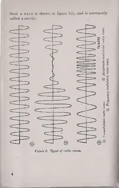
Such a wave is shown in figure 2®, and is commonly
called a carrier,)
Figure %, Types of radio waves.

b. A radio wave the amplitude or frequency of
which is varied in accordance with a signal is said to be
modulated. A radio wave the frequency of whichremains unchanged, but the amplitude of which is madeto vary in accordance with a signal, is said to be ampli-
tude-modulated (fig. 2©). A radio wave the amplitude
of which remains unchanged, but , the frequency of
which is varied in accordance with a signal, is said to
be frequency-modulated (fig. 2®).
5. CONTINUOUS-WAVE SIGNALS. Radiotele-
graph, or continuous wave (c-w), signals are produced
by keying an unmodulated carrier. An audible note
is obtained at the receiver by mixing the incomingr. f. signal with a locally generated signal. The local
signal is generated in the receiver by a device knownas a beat-frequency oscillator. The audible note fromthe receiver follows the keying of the transmitter, andintelligence is conveyed from the transmitter to. the
receiver by means of International Morse Code, Oneof the advantages of radiotelegraph, or c-w, signals is
that for a given power, greater range and sharper
tuning can be obtained than with any other type of
radio signal.
6. VOICE-MODULATED AND TONE-MODULAT-ED SIGNALS. These signals are made by combining
audio signals, from either a tone source or voice, withr. f. waves within the transmitter. The resultant
transmitted signal is either amplitude-modulated or
frequency-modulated (par. 4). In voice modulation,
many audio frequencies corresponding to the voice
sounds are present. Only one audio frequency is
present in tone modulation. At the receiver, the audio

component of the incoming wave is reproduced through
a headset or loudspeaker. It is possible to receive
tone-modulated radiotelegraph signals with a receiver
not equipped with a beat-frequency oscillator.
7. COMPARISON OF F-M AND A-M SYSTEMS.a. Carrier frequency. F-m systems require channel
widths of from 50 to 1.50 kilocycles for each station,
and very high carrier operating frequencies are re-
quired to accommodate a reasonable number of trans-
mitting stations. A-m systems operate oil narrower
channels and can be used with any practicable carrier
frequency.
b. Equipment location. F-m transmission and
reception is confined to approximate line-oj-sight paths,
because of the characteristics of high-frequency (h-f)
radio waves (pars. 9 to 12). Transmitters and re-
ceivers operating with amplitude modulation are less
restricted in location,
C. Interference. In f-m systems, a received signal
of approximately twice the strength of other signals will
completely block out the other signals. In some
instances, this strong signal may be an unwanted signal
from an adjacent f-m transmitter and the desired signal
cannot be heard. It may occasionally be possible to
shift the receiver antenna to a position that will bring in
the desired signal to the exclusion of all other signals.
In a-m systems, weaker signals are not blocked out and
may interfere with the reception of a stronger signal
This interference may be so great as to prohibit the
copying of messages except by a very experienced oper-
ator. (For methods of overcoming interference see
pars. 32 to 34, incl.)

8. DESIGNATION OF R-F BANDS. The radio fre-
quencies extend from about 20 kilocycles to over 30,000megacycles. Since different groups of frequencieswithin this broad range produce different effects in
transmission, the radio frequencies are divided intogroups, or bands. The bands used for military purposesarc as follows:'
Designation of t>and Authorizedabbreviation Frequency range
Very-low-freq uehcyLow-frequency. _
V-l-f
1-f
m-f. _ __ii-f
Below 30 kc.
30 kc to 300 ke.300 kc to 3000 kc.
3000 kc to 30 mcMedium-frequencyHigh-frequencyVery-high-frequency r
Ultra-high-frequencySuper-high-freq ueney
v-h-f
u-h-fs-h-f
30 mc to 300 mc.300 mc to 3000 me.Above 3000 mc.
SECTION II
GROUND WAVE AND SKY WAVE9. RADIO WAVE COMPONENTS. The wave radi-ated from a transmitting antenna may be regarded as
ponsisting of two parts. One part of the radiatedenergy travels -along the surface of the earth and is
called the ground wave. The, remaining portion is
radiated upward into space at an angle with the groundand is called the sky wave. The sky wave does notcome under the influence of the ground to any greatextent.
10. GROUND WAVE. The ground-wave componentof the radiated wave rapidly loses strength because of
spreading and absorption by the ground. The rapidity

of absorption is variable, being dependent upon the
type of earth surface, vegetation, and man-made
structures. No general statement can be made regard-
ing the distance that will be covered by the ground
wave for a given power or frequency. A radio wave of
given characteristics may extend several times as far
across salt water as across land. As a rule, more
moisture in 'the ground will result in less absorption,
and the distance covered with a given' power output
will increase. The loss in signal strength will generally
be more rapid at higher frequencies. At frequencies
above 20 megacycles, the ground wave is more or less
limited to the line-of-sight, or horizon, distance. Most
field radio communication is dependent upon the
ground wave.
11. SKY WAVE. a. The energy radiated upward by
an antenna travels skyward until it strikes a heavily
ionized (charged) region known as the ionosphere
(formerly called the Kennelly-Heaviside layer). The
distance of this layer varies from about 70 to 250 miles
above the earth. The ionosphere itself varies in depth
and degree of ionization, depending upon the time of
day, the season, and solar activity. There are also
changes from month to month, and from year to year'.
The paths of r. f . waves passing through the ionosphere
are refracted by the action of the ionization, or elec-
trical charge. Some of the sky waves penetrate the
ionosphere and are lost, but more often they are re-
fracted in their paths and reflected back to earth at
distant points. Whether or not the waves penetrate
the ionosphere or return to earth depends upon the
frequency of transmission, the time of day, the time of
year, and several other variable factors. Long-range
16

radio communication is accomplished by means of thesky wave.
b. In general, the distance between the transmitting
antenna and the point at which the sky wave first
returns to earth is greater at higher radio frequencies.
For a, given frequency, this distance is also greater at
night than in the daytime, and greater in winter thanin summer.
c. Sky waves may strike the earth, be reflected
back into the ionosphere, and be again reflected backto earth at a more distant point. This additional
reflection between earth and ionosphere is accompanied-by an attenuation of the radio wave, so that after a
number of such reflections (depending upon the original
power of the transmitter) the signal will usually be tooweak for the most sensitive receiver.
d. Above a certain high frequency and for a givendistance (the exact figure depending upon all the factors
mentioned previously), the sky wave is not refracted
enough to cause it to return to earth; it therefore
pierces the ionosphere and is lost in space. At suchvery high frequencies, all radio communication is
accomplished by means of the ground wave, or onapproximate line-of-sight radiation, which is regardedas part of the ground wave.
e. Below a certain frequency and for a given dis-
tance (the exact figure depending upon the factors'
mentioned above and also on radiated power, antennacharacteristics, atmospherics, and man-made interfer-
ence), the wave is absorbed to such an extent that it is
too weak to be used when it returns to earth. Belowthis frequency, called the lowest useful high frequency,communication is possible only by means of the groundwave.
13
f. There is thus an upper and a lower limit to the
frequencies which are useful for sky-wave communica-
tion over a given distance. Similarly, there is an upper
and a lower limit to the distances over which sky-wave
communication can he realized on a given frequency.
The lower limit is called the skip distance (par. 12), and
corresponds to the maximum usable frequency limita-
tion; the upper limit is called the distance range, and
corresponds to the lowest useful frequency limitation.
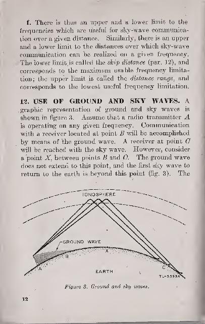
13. USE OF GROUND AND SKY WAVES. Agraphic representation of ground and sky waves is
shown in figure 3. Assume that a radio transmitter Ais operating on any given frequency. Communication
with a receiver located at point B will be accomplished
by means of the ground wave. A receiver at point Gwill be reached with the sky wave. However, consider
a point X, between points B and G. The ground wave
does not extend to this point, and the first sky wave to
return to the earth is beyond this point (fig. 3). The
IONOSPHERE
Figure S. Ground and sky waves.
VZ
=

distance from the transmitter to the point where the
first sky wave returns to earth is the skip distance.
In order for the transmitter to contact a receiving set
at point- X, it is necessary to select either a frequency
that will be returned to earth at this point, or one the
ground wave of which will extend to point X. If the
ground wa"ve were just short of reaching the desired
receiving point, it might be possible to reach it on the
same frequency by adding power to the transmitter..
SECTION III
ANTENNAS13. FIELD EXPEDIENTS. The antenna supplied
with a field radio set is designed to put out a strong
ground wave in all directions over the range normally
required. The antenna is compact and easily installed,
and for all normal operations no attempt should be madeto improve upon it. Under certain conditions, how-
ever, an increase in the normal range of the set may be
necessary. This can be accomplished by using either
of two easily constructed antennas. Wire for con-
structing either of those improvised antennas should be
of copper, size No. 12 or larger. If this, or other copper
wire, is not available, a satisfactory antenna can be
constructed with ordinary field wire.
14. SINGLE-WIRE-FED HERTZ ANTENNA, a.
This antenna receives its name from its transmission
line or feeder. It is also known as the "off-center-fed"
Hertz antenna, because the feeder is attached at a point
off center. In constructing this antenna, it is necessary
566396—44 3 13
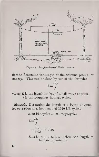
Figure 4. Single-wire-fed Hertz antenna,
first to determine the length of the antenna proper, or
flat top. This can be done by use of the formula:
468
where L is the length in feet of a half-wave antenna
i is the frequency in megacycles.
Example: Determine the length of a Hertz antenna
for operation at a frequency of 3920 kilocycles.
3920 kilocycles= 3.92 megacycles.
7 _468L~f=£1 = 119.38
Z=about 119 feet 5 inches, the length of
the flat-top antenna.
14

b. Having determined the length of the fiat top, add
an allowance for fastening insulators and then cut the
wire. From either end, measure a distance equal to
36 percent of the total antenna length. At this point,
remove any insulation and connect the feeder wire
securely to the antenna wire. The feeder is a single
wire long enough to reach from the transmitter to the an-
tenna. The feeder connection to the antenna should
be soldered whenever possible.
C. The antenna is now suspended as high above the
ground and as much in the clear as conditions permit
{fig. 4). Orient the antenna in such, a way that the
length of the flat top is perpendicular (broadside) to
the direction of the station to be contacted. Theinsulators used for holding the antenna should be
ceramic or glass. Hard, dry wood may be substituted
if ceramic or glass insulators are not available.
d. The following table shows the antenna length
and the point of attachment of the single-wire feeder
for most of the commonly used ratio frequencies:
APPROXIMATE LENGTH OF SINGLE-WIRE-FEDHERTZ ANTENNA FOR VARIOUS FREQUENCIES
Frequency(kc)
Antennalength (ft)
Feeder dis-
tance from oneend (ft)
Frequency Antennalength (ft)
Feeder dis-
tance from oneend (ft)
1500 312 112. 3 2100 222 79. 91550 302 108. 7 2150 218 78. 51600 292 105. 1 2200 213 76. 71650 284 102. 2 2250 208 74. 91700 275 99. 2300 203 73. 1
1750 267 99. 1 2350 199 71. 61800 260 S3. 6 2400 195 70. 21850 253 91. 1 2450 191 68. 81900 246 88. 6 2500 187 67. 3
1950 240 86. 4 2550 183 65. 92000 234 84. 2 2.600 180 64. 82050 228 82. 2650 177 63. 7
15

APPROXIMATE LENGTH OF SINGLE-WIRE-FEDHERTZ ANTENNA FOR VARIOUS FREQUENCIES—Continued
Frequency(fee)
Antennalength (ft)
Feeder dis-
tance from oneend (ft)
Frequency(to)
Antennalength (ft)
Feeder dis-
tance from oneend (ft)
2700 173 62. 3 4800 97. 5 35. 1
. 2750 170 61. 2 4850 96. 5 34. >7
2800 167 60. 1 4900 95. 5 34. 42850 164 59. 4950 94. 5 34.
2900 161 58.0 5000 93. 5 33. 62900 158 56. 9 5050 92. 5 33. 33000 156 56. 1 5100 92 33. 1
3050 153 55. 1 5150 91 32. 83] 00 151 54. 3 5200 90 32. 43150 148 53. 3 5250 89 32.
3200 146 52. 5 5300 88 31. 73250 144 51. 8 5350 87. 5 31. 53300 142 51. 1 5400 86. 5 31. 23350 140 50. 4 5450 86 30. 93400 138 49. 5 5500 85 30. 63450 136 48. 9 5550 84 30. 33500 134 48. 2 5600 83. 5 30.
3550 132 . 47. 5 ,5650 83 29. 83600 130 46. 8 5700 82 29. 53650 128 46. 1 5750 81. 4 29. 33700 126 45. 4 5800 81 29. 1
3750 125 45. 5850 80 28. 83800 123 44. 3 5900 79. 4 28. 63850 122 43. 9 5950 78. 8 28.43900 120 43. 2 6000 78. 28. 1
3950 118 42. 5 6050 77, 5 27. 94000 117 42. 1 6100 76. 8 27. 74050 115 41. 4 6150 76. 2 27. 44100 114 41. 6200 75. 5 27. 24150 113 40. 6 6250 75. 27.04200 111 40. 6300 74. 4 26. 84250 110 39. 6 6350 73.8 26. 64300 109 39. 2 6400 73. 2 26. 44350 108 38. 8 6450 72. 6 26. 1
4400 106 38. 2 6500 72. 25.94450 105 37. 8 6550 71. 5 25.74500 104 37. 4 6600 71. 25. 54550 103 37. 6650 70. 5 25.44600 102 36. 7 6700 70. 25. 24650 101 36. 4 6750 69. 5 25.
4700 100 36. 6800 69. 24. 84750 98. 5 35.5 6850 68. 5 24. 6
16
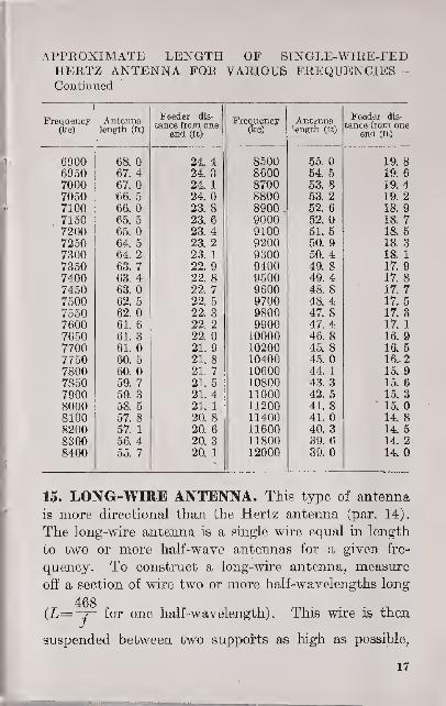
APPROXIMATE LENGTH OF SINGLE-WIRE-FEDHERTZ ANTENNA FOR VARIOUS FREQUENCIES—Continued
Frequency(kc)
Antennalength (ft)
Feeder dis-
tance from oneend (ft)
FrequencyOra)
Antennalength (ft)
Feeder dis-
tance from oneend (ft)
6900 68. 24.4 8500 55. 19. 86950 67. 4 24. 3 8600 54. 5 19. 6
7000 67. 24. 1 8700 53. 8 19. 47050 66. 5 24. 8800 53. 2 19. 27100 66. 23.8 8900 52. 6 18. 9
7150 65. 5 23. 6 9000 52. 18.77200 65.0 23. 4 9100 51.5 18. 5
7250 64. 5 23. 2 9200 50. 9 18. 37300 64. 2 23. 1 9300 50. 4 18. 1
7350 63. 7 22. 9 9400 49. 8 17. 9
7400 63. 4 22. 8 9500 49. 4 17. 87450 63. 22. 7 9600 48. 8 17. 77500 62. 5 22. 5 9700 48. 4 17. 5
7550 62. 22. 3 9800 47. 8 17. 3
7600 61. 6 22. 2 9900 47. 4 17. 1
7650 61. 3 22. 10000 46. 8 16.97700 61. 21. 9 10200 45. 8 16. 57750 60. 5 21. 8 10400 45. 16.. 27800 60. 21. 7 10600 44. 1 15. 9
7850 59. 7 21. 5 10800 43. 3 15. 6
7900 59. 3 21.4 11000 42. 5 15. 3
8000 58. 5 21. 1 11200 41. 8 15.
8100 57. 8 20. 8 11400 41. 14. 8
8200 57. 1 20. 6 11600 40. 3 14. 58300 56. 4 20.3 11800 39. 6 14. 2
8400 55. 7 20. 1 12000 39. 14.
15. LONG-WIBE ANTENNA. This type of antenna
is more directional than the Hertz antenna (par. 14).
The long-wire antenna is a single wire equal in length
to two or more half-wave antennas for a given fre-
quency. To construct a long-wire antenna, measure
off a section of wire two or more half-wavelengths long
468(£=-7- for one half-wavelength) . This wire is then
suspended between two supports as high as possible,
17

Figure 5. Typical long-wire antenna.
leaving enough wire at one end to reach and connect to
the transmitter antenna tuning unit (fig. 5). This type
^DIRECTION OF TRANSMISSION
THE LONGER THE ANTENNA THESMALLER IS ANGLE X AND THEGREATER THE POWER IN EACHMAIN LOBE
TL-55SIA
Figure 6. Radiation patt&rn for a long-wire antenna.
IS

of antenna should be constructed >so that it points in
the general direction of the stations to be contacted.
If the station is not contacted after a reasonable trial,
the 'antenna should be shifted so that it points in aslightly different direction, and another attempt made.A long-wire antenna radiates more energy in one direc-
tion than in another, and tbe pattern of radiation is
diagrammatically shown in figure 6. The directional
effect of long-wire antennas increases with added half-
wavelengths.
SECTION IV
FACTORS CONTROLLING RANGE OFCOMMUNICATION
16. FACTORS INVOLVED AT TRANSMITTER.a. Frequency. The ground wave is used for most field
radio communication. When the transmitter is oper-ating in the low-frequency band (30 to 300 kilocycles),
the range of the ground wave may be as great as several
hundred miles. This range becomes correspondinglyshorter as the operating frequency of the transmitter is
increased through the medium-frequency band (300 to
3000 kilocycles) to the high-frequency band- (3000 kilo-
cycles to 30 megacycles). When the transmitter is
operating at frequencies above 30 megacycles, the rangeof the ground wave is limited to the distance to thehorizon, called the line-of-sight radiation.. Certainlarge or fixed high-powered transmitters operating in
the high-frequency band make use of sky-wave radiationto establish fairly reliable communication over distancessometimes as great as 10,000 miles when necessary.
b. Power. The range of the transmitted signal will
19

be somewhat proportional to the amount of power
radiated by the antenna. That is, an increase in power
will result in some increase in range, and a power de-
crease will decrease the range. This relation is not
strictly proportional, however, and varies with fre-
quency and with the operating characteristics of various
types of radio sets. Under normal operating conditions
the transmitter should feed only enough power into the
radiating antenna to establish communication with the
receiving station. Transmitting a signal more power-
ful than necessary is a breach of signal security, since it
divulges the location of the transmitter to a much wider
area of possible enemy direction finders.
c. Antenna. For maximum transfer of energy, the
radiating antenna must be cut to the proper length for
the frequency of operation, and must be correctly
matched and tuned to the output tank circuit of the
transmitter. The condition of the local terrain plays
an important part in determining the radiation pattern,
and thus affects the directivity of the antenna and the
possible range of the set in the desired direction. If
possible, several variations in the physical position of
the antenna should be attempted to determine an opti-
mum operating position radiating the most energy in
the desired direction,
d. Capabilities of operator. The skill and tech-
nical capabilities of the transmitter operator play an
important part in obtaining the maximum, possible
range. The transmitter, coupling output, and antenna
feeder circuits must be correctly tuned to obtain maxi-
mum power output. When it is necessary to erect a
radiating antenna, it must be properly constructed
with regard to both electrical characteristics and con-'
dition of the local terrain.
30
J

17. FACTORS INVOLVED IN PATH OF TRANS-MISSION BETWEEN TRANSMITTING AND RE-CEIVING STATIONS, a. Conductivity of inter-
vening terrain. The type of terrain existing between
two field radio sets has an effect on the' ground wave,
known as ground conductivity. Flat prairie country
usually has a 'high value of conductivity, and there is
little absorption of the ground wave by the earth.
Large surfaces of water also have high conductivity.
Mountainous, rugged, and broken country usually has
a low value of ground conductivity, and in the immedi-
ate region of large mineral deposits and in deep ravines
and valleys there may be no radiation from the trans-
mitter due to complete absorption of the ground waveby the earth.
b. Height of intervening terrain. Large terrain
obstructions between the transmitting and receiving sta-
tions have an effect similar to that discussed in a above.
c. Distance between stations. Radio transmitters
having a limited range must work with receivers located
within this range. Large transmitters radiating both
ground and sky waves may be able to reach the receiv-
ing station with cither or both of these waves, depending
on the distance between the transmitter and receiver.
d. Skip distance factor. Large transmitting sets
using the sky wave as a primary means of communica-tion must consider the characteristics of the skip dis-
tance in reaching the desired receiving station. Atcertain times of day or night, and when the transmitter
is operating at certain frequencies, the receiving station
may lie within, the skip distance area and will not,
therefore, receive a signal from the transmitter.
18. FACTORS INVOLVED AT RECEIVER, a. Sen-sitivity and selectivity of receiving set. The sensi-
566S96—44 4 31

tivity is that characteristic which determines to howweak a signal a receiver is capable of responding. Theselectivity is the degree to which a receiver is capableof differentiating between the desired signal and signalsof other carrier frequencies. A properly aligned andefficiently operated radio receiver has nmxinvum valuesof selectivity and sensitivity which are determined bythe design of the equipment and, in general, cannot beexceeded. The inherent noise level of the receivercircuit is a limiting factor in the sensitivity of a re-ceiving set.
b. Receiving antenna. Erection, location, andelectrical characteristics are not as decisive in theoperation of the, receiving antenna as they are in thetransmitting antenna. The receiving antenna must beof sufficient length, however, in some cases must havecertain polarization characteristics, and must be prop-erly coupled to the input of the receiver circuit. Thecondition of the terrain in the vicinity of the antennamay affect the incoming r. f. signal in much the samemanner as described in paragraph 17a. *
C. Natural static. This type of static, also knownas atmospherics, consists of radio waves generatedfrom such natural sources as thunderstorms, and maytravel great distances. Static is present at most fre-
quencies, but diminishes considerably as the fre-
quency is increased. Reception at very high frequen-cies suffers little from this form of disturbance. Staticmay be reduced only by the employment of a highlyselective receiver and a directional receiving antenna.
d. Man-made static. This type of electrical inter-
ference is generated by most types of electrical de-vices, such as automobile and tank ignition systems,sparking brushes on motors and generators, and other
23

rotating machines. Whenever an electric spark occurs,
a train of radio waves is radiated over a fairly wideband of frequencies. For this reason, man-madestatic can best be eliminated or minimized at the source
rather than at the receiver. Cleaning the brushes of a
motor or generator, for example, will eliminate this
source of interference. Special power-supply "filters
are used in large installations operating from an a. c.
power source. At the receiver, the use of a directional
receiving antenna will eliminate some of the man-made static, provided the source of interference is notin the same direction as the transmitting station.
e. Interference from other transmitters onsame and adjacent frequencies. The selectivity ofa receiver should supply the necessary degree of sep-aration between the desired signal and any desired
carrier-frequency signals on adjacent frequencies. How-ever, when the selectivity is not sufficient to excludesignals from closely adjacent frequencies, and whensignals from other transmitters on the same frequencyare being received, the only solution is to change theoperating frequency, or arrange a schedule of opera-tion with the interfering transmitters.
f. Capabilities of operator. The skill and techni-cal capabilities of the receiver operator play an im-portant part in obtaining the maximum possible rangeof operation from the transmitter. The proper erec-
tion and location of the antenna and receiving set,
control over all tuning, and the resultant control everthe sensitivity and selectivity, are all factors directly
concerning the radio operator. Maximum sensitivity
at the receiver is necessary in order for the transmit U-r
to be operated with the lowest power required fur-
efficient communication.
M
CHAPTER 3
USE OF RADIO COMMUNICATION
19. FORMS OF RADIO COMMUNICATION, a.Radio is one of the principal means of signal communi-cation within all units of the Army. It is used fortactical control, fire control, administrative purposes,and for liaison between and within all units to whichthe equipment is available. Radio is used betweenrapidly moving units where wire or messenger com-munication is difficult; over large areas where wire ormessenger communication is impractical; and betweenhighly mobile elements, such as aircraft and motorizedand armored vehicles, where wire or messenger com-munication is impossible. Radio is especially adaptedto rapidly changing situations and, under certain con-ditions, may be the only means of signal communica-tion available.
b. Radiotelegraph® is normally employed betweenunits of higher echelons when the distances involvedare great. It may be used by lower units and overshorter distances when, by reason of the subject matter,cryptographed messages are required. InternationalMorse characters are used for radiotelegraphy by theArmy and Navy. (See TM 11-459.)
C. Radiotelephony is employed within the lowerechelons for person-to-person communication when,by reason of the nature of the message or the timefactor involved, secrecy is relatively unimportant. Itis especially suited for communication between air-
I
24

craft, between aircraft and ground stations, betweenvehicles in motion, between vehicles and ground sta-
tions, and between portable, individually carried radio
sets. It may be employed in some cases for commandand control purposes by commanders of units up to
divisions. The use of radiotelephony in combatrequires a high degree of training and discipline on the
part of the individuals concerned in order to render
transmission intelligible, to avoid congestion of the
carrier frequency, and to provide the necessary signal
security,
30. ADVANTAGES AND LIMITATIONS. Eadiocommunication has only one distinct advantage over
other types of signal communication. This advantage
is the relatively high degree of mobility of the system,
resulting from the fact that no physical circuits are
necessary to maintain the related stations. There are,
however, a number of important limitations of this
advantage of radio communication. The use of radio
in the field requires a careful consideration of these
limitations;
a. Relatively low traffic-handling capacity.
b. Susceptibility to interference from atmospherics,
from enemy communication and jamming station, andfrom friendly stations.
e. Range of communication is affected by the nature
of the terrain.
d. The possibility of the enemy's interspersal of
false messages, disguised as communications from
friendly stations.
e. Radio offers the enemy a volume of cryptograph e<!
messages for study, possibly resulting in an eventual
break-down of the code or cipher used.
M
__
f. Disclosure through the enemy's position-finding
equipment (see FM 11-20) of the approximate number,
types, and locations of operating radio transmitters.
g. Disclosure through enemy's traffic analysis (see
par. 46d) of disposition and probable movement of
troops. This method of obtaining intelligence by the
enemy does not require direction-finding equipment or
cryptographic analysis.
21. OVERCOMING LIMITATIONS. The limitations
outlined in paragraph 20 can be reduced in every case
by improving the general technique of the individual
radio operator with particular regard to operating pro-
cedure, signal intelligence, and signal security.
a. The traffic-handled capacity of a radio net can be
increased by a thorough training of operators and the
establishment of a proper net operating discipline.
b. Disadvantages resulting from interference can
best be overcome by thorough training and experience
of operating personnel. Friendly station interference
can be minimized by proper care in the assignment
of net frequencies. The use of radiotelegraph enables
trained and experienced operators to copy through all
but the most severe atmospherics. See paragraph 34
for information on methods of copying through enemy
jamming.
C. A careful selection of the location of the radio
set can minimize the effect of terrain features. Under
adverse circumstances, the power of the transmitter
may be increased in order to reach a receiving set
located in a region having poor ground conductivity.
d. The strict use of a frequently changed authentica-
tion system will systematically eliminate the enemy's
ability to deceive by transmitting false messages.
36

e. Cryptographic security can be preserved by ad-
herence to the unit Signal Operation Instructions,
which provide frequent changes in code and cipher
construction.
f. The amount of information revealed to enemyintelligence units by their position-finding equipment
and traffic analysis can be minimized by strict obser-
vance of signal security during transmission, and by
deceptive operation.
(1) Radio operators must be thoroughly familiar with
all signal security rules and regulations, and the unit
Signal Operation Instructions,
(2) A radio transmitter will use only the minimumamoxmt of power necessary for reliable communication
with the station or stations involved.
(3) The use of radio must be kept to a minimum at all
times, and limited to communication which is absolutely
necessary.
(4) The transmission of call signs will be limited, and
the calls will be changed frequently in accordance with
the signal operation instructions.
(5) A careful control of the volume and nature of traffic
must be maintained.
(6) "Blind," or fake messages may be transmitted by a
station to deceive the enemy during certain critical
operations, such as troop movements, or preparations
for an attack in force.
(7) The location of transmitting sets must be changed
frequently to disorganize the enemy's position-finding
deductions.
(8) "Dummy" transmitting stations may be established
at remote locations further to confuse the enemy's
position-finding interferences.
27

32, TYPES OF RADIO SETS.—The Joint Army-Navy Nomenclature System classifies all radio sets
according to the following types:
a. Airborne. A set installed and operated in an air-
craft.
b. Air transportable. A set specially designed to
be transportable by air, according to specification or
military characteristics.
c. Ground, fixed. A large set erected and operated
at a permanent location, usually for long-distance
communication
.
d. Ground, general ground use. A set which can
be installed and operated for two or more types of
ground use, that is, a set which can be used both as a
vehicular ground set and a transportable ground set, or
a set which can be used both as a vehicular ground set
and a portable pack ground set.
e. Ground, mobile. A set installed as an operating
unit in a motor vehicle which has no function other than
transporting the radio equipment.
f. Ground, pack or portable. A set capable of
being carried by a man (or a horse) and operated, while
stationary or in motion, by one person. .This class in-
cludes those sets commonly known as "walkie-talkie"
and "handy-talkie."
g. Shipboard. A set installed and operated from
aboard a surface vessel.
h. Ground, vehicular. A set installed in a vehicle
which is designed for functions other than carrying
radio equipment, such as a set installed in a tank or
armored car,
i. Ground, transportable. A semiportable set,
capable of being transported from place to place, but
38

requiring a conveyance if moved for any considerable
distance.
j. General utility. A set which can be used in two
or more of the general type installations: airborne,
shipboard, and ground.
23. CLASSIFICATION OF RADIO SETS. a. Typeof modulation. A radio set may be classified as being
either amplitude-modulated (a-m) or frequency-mod-
ulated (f-m).
b. Type of signal. A radio set may be classified as
continuous-wave (c-w), tone-modulated, or voice-mod-
ulated, according to the kind of signals it transmits or
receives. Tone-modulation signals are considered as
a form of amplitude modulation. Voice-modulated
signals may be either amplitude modulated or frequency
modulated.
24. TRAINING OF RADIO OPERATORS. General
teaching methods are discussed in TM 11-450. Re-.
quirements of radio specialists are contained in AR 615—
26. TM 11-459 deals with instruction in the use of
International Morse characters. Training in radio-
telegraph operating procedure is, contained in TM 1 1-
4 54 j and further information concerning combined
radiotelegraph procedure is given in FM 24-6, 24-10,
and 24-12. Radiotelephone operation procedure is
discussed in FM 24-9.
39

CHAPTER 4
FIELD RADIO STATIONS
SECTION I
LOCATION OF RADIO STATIONS
25. SELECTION OF SITE. The selection of a site for
operation of an Army radio station is based on the
following:
a. Technical requirements.
b. Cover and concealment.
C. Local communication.
26. TECHNICAL REQUIREMENTS. A radio station
should be located in a position that will assure com-
munication with all other stations with which it is to
operate. In order to obtain efficiency of transmission
and reception, the following factors should be con-
sidered:
a. Terrain.
(1) Hills and mountains between stations limit the
range of radio sets. When operating in terrain of this
nature, select positions relatively high up on the slopes.
Avoid locations at the base of a cliff, or in a deep ravine
or valley. For operation at frequencies above 20
megacycles, choose whenever possible a location that
will give line-of-sight communication.
(3) Dry ground has low conductivity and limits the
range of the set. If possible, locate the station near
30
moist ground which has higher conductivity. Water,
particularly salt water, greatly increases the distances
that can be covered.
(3) Trees with heavy foliage absorb radio waves, andleafy trees have a more adverse effect than evergreens.
The antenna should be well clear of all foliage and dense
brush to obtain the maximum range.
b. Man-made obstructions.
(1) Do not select a position in a tunnel, or beneath an
underpass or steel bridge. Transmission and reception
under these conditions will be almost impossible, owing
to high absorption of the r. f. waves.
(2) Buildings between radio stations will hinder trans-
mission and ' reception. This is particularly true of
steel and reinforced concrete types.
(3) All types of pole wire lines such as telephone, tele-
graph, and particularly high-tension power lines should
be avoided in selecting a site for the radio set. Such
wire lines absorb power from radiating antennas
located in close proximity. They also introduce humand noise interference in receiving antennas.
(4) Positions adjacent to heavily traveled roads and
highways should be avoided. In addition to the noise
and confusion caused by tanks and trucks, ignition
systems in these vehicles may cause local electrical
interference.
(5) Battery charging units and other generators should
not be located too close to the radio station.
(6) Radio stations should not be located too close to
each other.
(7) Radio stations should be in quiet localities. Thecopying of weak signals requires great concentration by
the operator, and his attention should not be diverted
by extraneous noises,
31

c. Local command requirements. Radio stations
should be located at a sufficient distance from the unit
headquarters or command post which they serve to
prevent long-range enemy artillery fire or aerial bom-bardment directed at the stations from striking the
command post. Such enemy fire would result fromdetermination of the operating stations' location byhostile position finders. The minimum distance be-
tween the command post and the radio stations should
be 200 yards.
27. COVER AND CONCEALMENT. Positions should
be selected that will provide maximum cover and con-
cealment consistent with good transmission and recep-
tion.
a. The open crests of hills and mountains should beavoided. While such a location may permit ideal trans-
mission and reception, the resulting silhouette makes anexcellent target for enemy guns. A slightly defiladed
position just behind the crest will give better conceal-
ment.
D. Many transmitters and receivers can be installed
just below the surface of the ground in holes similar
to slit trenches, thereby enabling the operator to main-tain communications under severe battle conditions.
For more permanent battlefield installations, the equip-* ment may be located on a "shelf" just below the surface
of the ground in fox holes. This will allow the opera-
tor greater freedom of movement. The antenna mustextend above the surface of the ground to permit normalcommunication
,
C, All permanent and semipermanent positions
should be properly camouflaged for protection against
both aerial and ground observation. (See FM 5-20.)
33

The antenna must bo kept free of camouflage material
or other obstructions.
28. LOCAL COMMUNICATION. Contact ' should
be maintained between the radio set and the message
center at all times either by local messenger or field
THESE PLACES ARE BAD FOR RADIO
BUT THESE ARE GOOD
^ -.? V^C^*"*-!- .^jr^
GOOD BETTERION LEVEL GROUN r>m<ti ifiHT RISE
BEST TI-M71A
BIG HILLI
Figure 7, Selecting location for a radio station.
:i3

telephone. The station should also be readily acces-
sible to the unit commander and his staff.
39. FINAL CONSIDERATIONS. It may often be
impossible to satisfy all the desirable conditions for
the location of a radio station, and a compromise,
.
depending upon the situation, may have to be made.
If radio communication cannot be established in one
location, the set should be moved a short distance and
another attempt made.
SECTION II
RADIO CALL SIGNS
30. ASSIGNMENT OF CALL SIGNS. All radio sta-
tions are identified by call signs. These call signs are
allotted by the Chief Signal Officer and are assigned
by standing operation instructions to various Armystations in the field. Detailed procedure for assigning
radio call signs is contained in FM 11-5.
31. PURPOSE OF CALL SIGNS. Radio communica-
tion is established by a call and answer method. Acall sign consists of one or more characters used to
afford a short and secure means of conveying the
identity of stations, commands, and commanders. Thevarious types and uses of radio call signs are discussed
in TM 11-454.
34
SECTION III
INTERFERENCE AND JAMMING32. RECEPTION THROUGH STATIC AND IN-TERFERENCE. There are few receiving locations
entirely free from either natural or man-made static,
and such interference may become extremely trouble-
some at times. Under these conditions, the following
steps should be taken to improve reception:
a. If the receiver is equipped with a crystal filter,
this highly selective device can be used to eliminate
much of the extraneous noise frequencies on either side
of the desired signal.
b. The receiving antenna should be kept in the open
and free from contact with tree limbs, shrubs, or other
obstructions.
C. If the receiving antenna is provided with an ex-
ternal connection, the length of the antenna should be
varied. Increasing or decreasing the length of the
antenna may sometimes result in better reception of
the desired signal.
d. The volume control of the receiver should be ad-
justed to the lowest level at which the desired signal can
be heard.
e. Headphones should be used in preference to a
loudspeaker.
33. JAMMING, a. The transmission of radio signals
intended to block out or interfere with radio communi-
cation is known as jamming. Deliberate jamming of
radio communication by the enemy must be expected,
since the enemy wishes to cause disorganization and
panic among troops through impairment or disruption
of the Army radio communication system.
35

b. Jamming is more or less effective depending upon
the power of the jamming transmitter and the type of
interference being radiated. Jamming signals mayconsist of keyed continuous waves, tone, voice, music,
imitation static, or other types of noise signals. The
interfering waves may be undamped, amplitude-
modulated, frequency-modulated, or a combination of
these. The frequency of the jamming transmitter
normally can be changed quickly to follow any fre-
quency shifts made in the radio sets being jammed. Anumber of jamming transmitters may be used simul-
taneously.
34. REDUCING EFFECTIVENESS OF JAMMING.a. Critical military operations should include plans for
maintaining communication despite interference created
by.enemy jamming transmitters. Should enemy jam-
ming necessitate, signal operation instructions should
include assignments of widely varying alternate fre-
quencies, if available, with rules for their use.
1). Enemy jamming on one frequency may be dis-
continued if it is thought that the channel is no longer in
use. It is, therefore, a good expedient to maintain
"dummy" transmissions on a frequency being jammed,
in the hope that the enemy will continue to use jamming
equipment on that frequency rather than transfer to
some other frequency.
C. Radio operators should be thoroughly trained to
cope with jamming interference (par. 35). Operators
should be able to copy messages through heavy inter-
ference of all types. It has been found that, in general,
tone modulation is more readable through jamming
than c-w or voice modulation.
36

35. TRAINING OF OPERATORS. Radio operators
must be thoroughly trained to deal with jamming inter-
ference whenever it occurs. The effectiveness of
jamming can be minimized if the radio operator is
trained to
—
a. Copy messages through sustained periods of in-
tense static and man-made interference.
I). Use a crystal filter, if one is provided with the
receiver.
e. Authenticate all incoming messages (the enemymay intersperse jamming with false messages).
d. Change call signs and shift frequencies promptly,
as directed.
e. Eliminate preliminary calling, requests for reports
on signal strength, and other routine messages which are
not indispensable.
f. Guard against the possibility of panic at the first
indications of jamming. Expect enemy, jamming andhave the determination to get the message through
under any condition.
SECTION IV
OPERATING REGULATIONS36. GENERAL, a. Radio operating procedure is dis-
cussed in TM 11-454, FM 24-6, FM 24-9, EM 24-10,
EM 24-11 , andFM 24-12. (See par. 2.) All operating
procedure and regulations are to be in accordance with
these manuals. Deviation from authorized procedure
usually results in delaying traffic and is strictly for-
bidden.
b. Radio stations will transmit only those messages
authorized by competent authority. All transmissions
37

and messages will be regarded as official communica-tions.
C. Radio stations will be supplied with telephone
communication whenever practicable, and especially
when the station is remote from the command post.
(I. Close cooperation with the message center is
essentia]
.
e. No superfluous calls or signals of any kind will betransmitted, and the unauthorized use of plain languageis prohibited.
f. Radio operators will be instructed in maintaining
communication security. (See sec. V.)
37. METHOD OF SETTING STATIONS ON FRE-QUENCY, a. General. A frequency standard is anydevice capable of generating a signal of known fre-
quency, and/or receiving a signal and accurately
measuring its frequency. To set either the receiver or
the transmitter frequency on the frequency of a stand-
ard, a process known as zero beating is used. (If the
transmitter is crystal-controlled, merely select the
proper crystal and check the frequency with the fre-
quency standard.)
b. Zero beating receiver to frequency standard.
(1) Turn on receiver and frequency standard, andallow sets to warm up (for 15 minutes if possible).
(2) Set frequency standard on assigned frequency.
(Do not move frequency standard dial after it has beencorrectly set.)
(3) Turn on receiver beat-frequency oscillator.
(4) By reference to receiver calibration chart, or to
receiver dial if it is directly calibrated in frequency,
set receiver dial on approximately the assigned fre-
quency, i
38
(5) While listening in receiver headset, rotate receivertuning dial until signal from frequency standard is
heard as a high-pitched whistle.
(6) Continue rotation of receiver dial until whistledrops to a very low note, or disappears entirely, andthen begins to rise in pitch. Reverse the direction of
rotation until whistle again drops4to the lowest pitch
or disappears. If there- is broad tuning at zero beat;that is, if the receiver can be tuned over a small rangeon the dial before the whistle reappears, care shouldbe taken to place receiver dial midway between thesetting at which the whistle disappears and thai atwhich it reappears. Just before reaching zero beat,
switch frequency standard off and on to make certainthat the signal is the one emitted by the frequencystandard. The whistle should disappear and reappear.
(7) The receiver is now on the same frequency as thefrequency standard and is said to be in zero beat with it.
(8) For reception of voice or tone transmissions, turnoff the beat-frequency oscillator of the receiver.
(9) For c-w reception, adjust the beat-frequency oscil-
lator control until a pleasing note is" hoard. If thereceiver has no beat-frequency oscillator control, turnthe receiver dial slightly to the high-frequency side
of the zero-beat setting and adjust for a pleasing note.
(10) If some stations in the net are not heard at the
setting, they may be slightly off frequency. Locatethem by tuning slightly to each side of the correct
frequency.
c. Zero beating transmitter to frequency stand-ard.
(1) Turn on frequency standard, and allow aet bo
warm up (for 15 minutes is possible).
(2) Listen on the assigned frequency. If other itfl
00
tions are working, wait until they are through in order
to avoid causing interference.
(3) If transmitter is equipped with side-tone feature,
take the necessary steps to render this device inopera-
tive during the adjustment period. In many Armysets this can be accomplished by making the initial
zero-beat adjustment in the voice position.
(4) Turn on transmitter and allow tubes to warm up.
(5) Set frequency standard on assigned frequency by
referring to the calibration chart. (Do not movefrequency standard dial after it has been correctly set.)
(6) By reference to transmitter calibration chart, tune
the transmitter to approximately the assigned frequency.
(7) Close the transmitter key (send long dashes—do
not hold key down). While listening in headset of
frequency standard, slowly rotate the transmitter
tuning dial until high-pitched whistling notes are
heard. These notes should correspond to the keying
of the transmitter.
(8) Continue rotation of transmitter dial until the
whistling drops to a very low note, or disappears
entirely, and then begins to rise in pitch. Reverse
the direction of rotation until whistling again drops
to its lowest pitch or disappears. If there is broad
tuning at zero beat, that is, if the transmitter dial can
be rotated a short distance after whistling disappears
before it reappears, care should be taken to set the
transmitter dial midway between points where the
whistling disappears and reappears.
(9) If adjustment is made with switch in voice
position and c-w operation is desired, turn the switch
to c-w position and make final zero beat adjustment.
(10) The transmitter is now on the same frequency
as the frequency standard and is said to be in zero
10

beat with it. The tuning dial should be . locked at
this setting, if a dial lock is provided.
38. USING FREQUENCY METER SET SCR-311-(*) AS FREQUENCY STANDARD, a. Prep-
aration of SCR 211-{*).
(1) Turn on frequency meter and allow set to warmup (15 mimites if possible).
(2) Set frequency meter to assigned frequency.
(3) Connect a short antenna (2 to 3 feet) to the
antenna binding post. Do not connect antenna
terminal directly to any part of the receiver or trans-
mitter being adjusted.
b. Adjustment of receiver.
(1) Turn on receiver and allow to warm up.
(2) Set the receiver dial on approximate assigned
frequency.
(3) Turn on beat-frequency oscillator.
(4) Zero bear receiver to the frequency meter.
(5) Adjust receiver for type of reception desired (voice,
tone, c-w).
c. Adjustment of transmitter.
(1) Turn on transmitter and allow to warm up.
(2) Set transmitter tuning dial(s) to approximate
assigned frequency.
(3) Zero beat transmitter to frequency of SCR-211-(*).
(4) Lock transmitter tuning dial(s) at zero-beat
setting.
Note. The symbol (*) is used in place of the suffix letters in
equipment titles to designate all models of a series.
39. NET CONTROL STATION AS FREQUENCYSTANDARD. When no SGR-211-(*) or equivalent is
available, another station in the same net (preferably
41

the net control station) should be used as the frequency
standard. The station should be identified by call
letters and authentication.
a. Adjustment of receiver.
(1) Turn on receiver and allow it to warm up.
(2) Tune receiver to approximate assigned frequency.
(3) Tune in net control station (or other station to be
used as standard) and zero beat to the received signal.
(i) Do not change the frequency setting of the receiver
after zero beat is obtained. The receiver will be used as
a frequency standard for the transmitter. Hence, it
-must be left at the setting of zero beat with the net
control station.
p. Adjustment of transmitter.
(1) Turn on transmitter and allow to warm up.
(2) Set tuning dial(s) on approximate assigned fre-
quency.
(3) Zero beat transmitter to receiver.
(4) Lock transmitter tuning dial(s) at zero-beat
setting.
c. Procedure when receiver has no heat oscillator
(voice or tone operation only).
(1) Tune in frequency standard signal, adjusting re-
ceiver tuning until signal is received at maximumstrength.
(2) Reduce receiver gain control to a low setting.
(3) Adjust transmitter to approximate assigned fre-
quency.
(4) Turn on transmitter and allow it to warm up.
(5) While speaking into the microphone in a low tone of
voice (or with the tone oscillator turned on), rotate the
transmitter tuning dial until voice or tone is heard in
receiver headset at maximum volume and clarity.
42

(6) If the transmitter is known to be on correct fre-
quency, the above procedure can be followed, but the
receiver should be tuned to the transmitter, rather thanthe transmitter to the receiver.
40. NO FREQUENCY STANDARD AVAILABLE.a. An approximate adjustment may be made byselecting the receiver or transmitter as a standard. If
the transmitter is crystal-controlled, it should be chosen
as the frequency standard. If the transmitter is of the
master-oscdlator power-amplifier type of circuit, the
receiver may be more accurately calibrated. Pastoperating experience should make it possible to de-
termine which unit to use.
b. Within the continental United States, receiver
calibration may be checked by tuning to either of twostandard frequencies transmitted from station WWV(5000 and 15000 kilocycles). Outside the continental
United States, any station of known frequency, within
range of the receiver, may be used for checking pur-
poses. After selecting one unit as a standard, zero
beat the other unit to it.
41. SUMMARY OP FREQUENCY CALIBRATION.a. Listen on a selected frequency before making anytransmitter adjustments, so that unnecessary inter-
ference with friendly stations may be avoided.
b. In zero beating a transmitter to another unit,
care must be taken to keep the transmitter on the air
for as short a time as possible. The purpose of this
precaution is to avoid unnecessary interference with
friendly stations, and to provide the enemy with the
least possible chance for locating the position of the
radio station by means of direction-finding equipment.
43
MH^H^H

c. "Dummy" antennas, when available, should, be
used for all transmitter tuning adjustments.
42. TRANSPORTATION OF FIELD RADIOEQUIPMENT. Radio equipment is comparatively
delicate and its serviceability is governed to a great
extent by the care with which it is packed for transpor-
tation. Operating equipment will be packed and loaded
in such a manner as to protect it from dust and dirt,
weather, shocks of the road, and injury from other
articles loaded in the same vehicle.
SECTION VCOMMUNICATION SECURITY
43. GENERAL, a. Communication security is the
safeguarding of friendly radio communication against
the availability and intelligibility of such communica-
tions to hostile persons or agencies.
b. The radio transmitter is a prolific source of intelli-
gence to the enemy in field operations. Every radio
transmission, regardless of its nature, offers information
to an alert enemy. Further, radio operators have
equipment and documents in their possession which
are extremely valuable to the enemy. It is necessary,
therefore, that all radio operators have a comprehen-
sive understanding of general communication security
(FM 11-35) and radio communication security (TM11-454).
c. Radio security is the responsibility of all personnel
concerned with radio communication. It consists not'
only of guarding what is transmitted, but of limiting
the use of radio to necessary transmissions.
44
d. Communication security consists of three prin-
cipal components, namely:
(1) Physical security,
(2) Cryptographic security.
(3) Transmission security,
44. PHYSICAL SECURITY, a. This security con-
sists of the protection of com immication equipment,
messages, cryptographic systems, and documents from
capture, theft, loss, or inspection by unauthorized
persons or agencies. This physical protection is the
responsibility of all radio communication personnel.
The procedure for handling classified material is
specified in AE. 380-5.
b. Field radio operators must be alert at all times to
safeguard signal communication equipment and mate-
rial from seizure by the enemy. Orders for the destruc-
tion of equipment (par. 49) will be carried out promptly
and thoroughly. The loss or compromise of communi-
cation material will be reported immediately.
45. CRYPTOGRAPHIC SECURITY. Messages will
not be sent in the clear unless specifically authorized by
higher authority. Message center personnel are pri-
marily concerned with the ciphering and deciphering
of messages, but radio operators must observe all the
rules of cryptographic systems hi use.
46. TRANSMISSION SECURITY, a. General.
This security concerns the prevention of enemy inter-
ception of radio, communications, and the minimizing of
information which may be obtained by the enemy from
such communications by means other than crypta-
naiysis. The radio operator is primarily concerned
45

with this type of communication security. (See TM11-454.)
b. Interception. All messages transmitted by radio
are susceptible to interception by hostile receivers.
Using the minimum power necessary to maintain com-
munication will limit enemy interception, and will also
lessen interference with friendly stations. In some
cases, the sky waves (pars. 10- and 11) may travel sev-
eral hundred miles into enemy territory. The strength
of signals reflected back to earth at such distant points
can be limited by a reduction in power at the trans-
mitter.
c. Direction finding. Any radio transmitter can
be located by enemy direction-finding stations, which
are effective on nearly all frequencies. Since these
hostile stations are less likely to obtain accurate
bearings on short transmissions, periods of operation
in the field should be as brief as possible.
d. Traffic analysis.
(1) Although all messages may be cryptographed, a
systematic analysis of intercepted radio traffic mayprovide the enemy with much useful information.
This traffic analysis is based upon
—
(a) Amount of traffic and length of messages.
(b) Call signs.
(c) Routing and relay instructions.
(d) Precedence (priorities).
(e) Procedure signs and operating signals.,
(f) Times of origin and receipt.
(2) The enemy will quickly perceive that certain mili-
tary actions will result from the transmission of certain
types of radio messages.
e. Security measures. Transmission security to
combat traffic analysis and all other enemy intelligence
46

activities is based on the following defensive measures:
(I) Minimum use of field radio sets.
(3). Use of minimum power necessary to maintain
communication.
(3) Strict compliance with radio silence restrictions.
(4) Eliminating unnecessary and unauthorized trans-
missions (such as informal conversations).
(5) Use of authorized procedures only.
(6) Correct use of radio call signs.
(?) Elimination of superfluous routing instructions in
message headings.
(8) Strict control of routine test transmissions in order
that their timing and volume will give no advance
information of impending operations.
(9) Transmitting all messages at the copying speed of
the slowest operator in the net to avoid repeating mes-
sages or message groups.
(10) Authenticating messages.
(II) Tuning of transmitters with dummy antennas, or
with the normal antennas disconnected, if possible.
(12) Maintaining correct frequency assignments.
(13) Using broadcast . and intercept methods. (See
TM 11-454.)
(14) Frequent changing of station locations.
(15) Maintaining radio watches on designated fre-
quencies and at prescribed times.
(16) Avoiding the development of any characteristic
keying habits or personal phrases by a particular radio
operator.
47. VOICE TRANSMISSION SECURITY. In radio-
telephone conversations, all personnel concerned must
avoid revealing information by the careless mention of
places, names of units or personnel, etc. Wording of
47

Toice transmission should be premeditated. Names of
units are not to be mentioned in clear, either in the
heading or text of a radiotelephone message.
48. DISCREPANCY REPORTS, a. Friendly radiostations shoidd be monitored by radio intelligence units
to insure that transmission security rules are not vio-
lated, and that proper radio procedure is being used.
Discrepancies noted should be reported to the signal or
communication officer concerned for appropriate action.
Such a report contains the following informationrelative to the observed station (s):
(1) Callsign(s).
(2) Frequency.
(3) Date of transmission.
(4) Time of transmission.
(5) Actual transmission (s).
(6) Specific reference to the paragraph of authoritative
document which has been violated.
b. The primary purpose of discrepancy reports is to
improve radio communications by educating the opera-
tors concerned. If, however, it is obvious that a viola-
tion is intentional or due to carelessness, disciplinary
action should be taken.
SECTION VI
DESTRUCTION OF EQUIPMENT
49. PURPOSE OF DESTRUCTION. Personnel con-
cerned with the operation of radio equipment should
be thoroughly prepared to destroy such equipment whenordered by a higher headquarters, or when in im-
48
mediate danger of capture by the enemy. Completedestruction of the equipment will deny the enemy the
use of it or airy parts thereof, as well as any informa-
tion concerning its design. Prescribed methods for
equipment destruction are included hi Technical Manu-als and other publications. In general, the instructions
contained in paragraphs 50 and 51 will apply,
50. PRIORITY OF OBSTRUCTION. Certain parts
of radio equipment must be destroyed to an extent suffi-
cient to prevent their future use or reclamation. Theparticular importance of these parts requires the pre-
scription of the following scale of priorities:
a. Parts which are nonstandard and unusual in de-
sign, from eith er a mechanical or an electrical standpoint.
There is little likelihood that the enemy can replace
such specialized parts, particularly if all captured units
of a given item have the same nonstandard componentdestroyed.
lb. Critical units. The enemy is less likely to be able
to replace these than noncritical units.
c. Parts interchangeable with other equipment.
These units are destroyed or damaged to prevent the
enemy from using them to salvage other types of de-
stroyed equipment.
d. AH other parts.
51. GENERAL METHODS OF DESTRUCTION.a. Radio sets.
(1) Shear off all panel knobs, dials, switches, etc., with
an axhead. Break open the compartment by smashing
in the panel face. Then knock off the top, bottom, andsides of the compartment. The object is to destroy the
panel and expose the chassis.
49
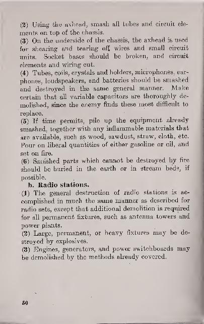
(2) Using the. axhead, smash all tubes and circuit ele-
ments on top of the chassis.
(3) On the underside of the chassis, the axhead is used
for shearing and tearing off wires and small circuit
units. Socket bases should be broken, and circuit
elements and wiring cut.
(4) Tubes, coils, crystals and holders, microphones, ear-
phones, loudspeakers, and batteries should be smashed
and destroyed in the same general manner. Makecertain that all variable capacitors are thoroughly de-
molished, since the enemy finds these most difficult to
replace.
(5) If time permits, pile up the equipment already
smashed, together with any inflammable materials that
are available, such as wood, sawdust, straw, cloth, etc.
Pour on liberal quantities of either gasoline or oil, and
set on fire.
(6) Smashed parts which cannot be destroyed by fire
should be buried in the earth or in stream beds, if
possible.
b. Radio stations.
(1) The general destruction of radio stations is ac-
complished in much the same manner as described for
radio sets, except that additional demolition is required
for all permanent fixtures, such as antenna towers and
power plants.
(2) Large, permanent, or heavy fixtures may be de-
stroyed by explosives.
(3) Engines, generators, and power switchboards maybe demolished by the methods already covered.
50

CHAPTER 5
CONTROL AND SUPERVISION OFRADIO ACTIVITIES
53. CLASSIFICATION OF ACTIVITIES. Radio ac-
tivities within the theater of operations are classified as
being either military or civil.
a. Military activities include the strategic, tactical,
and administrative use of radio communication, the col-
lection of signal intelligence, the location of air and sea
targets by radar, and radio aids to navigation.
ta. Civil radio activities, both private and commercial,
are discussed in FM 1 1-5.
53. MILITARY RADIO COMMUNICATIONACTIVITIES, a. Strategic.
(1) Control of strategic ground forces.
(2) Control and direction of strategic air operations.
(3) Communication, by means of the War Department
net, between zone of interior and theaters of operations,
(4) Long-range air reconnaissance.
(5) Other strategic operations.
b. Tactical.
(1) Control of tactical ground forces.
(2) Control and direction of tactical air operations.
(3) Close-range air reconnaissance.
(4) Ground reconnaissance.
(5) Other tactical operations.
51

e. Administrative.
(1) Communication by means of the War Departmentadministrative net.
(2) Army Airways Communication System.d. Other types.
(1) Transmission of standard frequency signals.
(2) Transmission of standard time signals.
(3) Broadcasting.
(a) Propaganda.
(b) Entertainment for friendly troops.
54. OTHER MILITARY ACTIVITIES, a. Radiointelligence activities, which are concerned primarilywith the collection of signal intelligence rather thanwith signal communication, are discussed in FM 11-35and FM 11-20. Radio security practices are estab-lished in Standing Operating Procedures and publishedin Signal Operation Instructions.
b, The location of friendly and hostile aircraft andsurface vessels by means of radar is a function of theAircraft Warning Service (FM 11-25) in coordinationwith other Government agencies.
c. Radio aids to navigation are maintained and oper-ated by the Army Air Forces.
55. CONTROL AND SUPERVISION OF ACTIVI-TIES. The signal system in an infantry division nor-mally will include from 50 to 60 radio nets; an armoreddivision may use from 100 to 130 nets. Thus, in a thea-
ter of operations in which several divisions are engaged,the total number of radio nets is very large. The oper-ation of a system of such broad scope requires a highorder of supervision and control to prevent interference
among radio units. The following steps are taken to
attain this supervision and control:
53

a. The assignment of call signs to all radio stations in
the theater of operations.
b.' The assignment, as effectively as possible, of non-
interfering frequencies to the various nets. If neces-
sary, certain nets may be silenced when others on the
same frequency have more important traffic to transmit.
C. The close supervision of all net operations t'o insure
the observance of orders and regulations contained in
the Signal Operation Instructions and the Standing
Operating Procedures. (See FM 11-20).
<s;i

INDEX
ParaKr:i]i!i
Airborne sets
Air transportable sets 22
Amp] itude of radio waves 3
Amplitude-modulated radio waves 4, 7
Antenna:Functioning 13
Half-wave, calculating length 14
Long-wire 15
Single-wire-fed, Hertz . . _ 1 14
Audio frequencies"
Authentication of messages-. . 21, 35, 46
Bands, frequency, designation 8
Beat-frequency oscillator 5,37
Call signs:
Assignment ,-30, 55
Purpose 31
Security measures regarding 46, 48
Camouflage ^7
Carrier waveCivil radio stations 52
Combat uses of radio 19
Command posts, distance to radio stations,-- 26, 28
Communication security 36, 43-47
Conductivity of ground __.____ 17
Continuous-wave (c-w) signals 5
Copying, through enemy jamming 34, 35
Cover and concealment 27
Cryptographic security 43, 45
Crystal filter 32.3S
Destruction of equipment 49-5
1
Direction finding, enemy 46
Directional antenna 15
Discrepancy reports 48
Dummy stations 21, 34
onFixed ground sets **
Pago
28
28
3
s ,8
13
13
17
13
7
26, 37, 45
9
7, 38
34, 52
34
45 48
32
5
51
24
30 33
37 44
21
7
36 37
32
44 45
35 37
48
45
17
IS
2(1 :;<;
28

28
28
Frequency: Paragraph pageAssignment 55 . 52Calibration 37-41 38Definition 3 gDesignation of bands g 9Effect on transmission range 10,11 16 9 10 19Meter set SCB.-211- (*), use
' '33 '41
Security measures regarding 4g 43Standard, setting stations on 37-41 38
Frequency-modulated radio waves 4, 7 5
General utility sets 22Ground sets, fixed, portable, and utility 22Ground wave. _____ 9,10,12 9,12
Heaviside layer ]j -jn
Hertz single-wire-fed antenna 14 13
Intelligence
:
Enemy, revealing information to.. 20, 21, 43-47 25, 26, 44Friendly radio intelligence activities 40
'
43Interference:
Causesr 26 30
In frequency-modulated and amplitude-modulated systems 7 g
Limitations of radio 20 25Methods of overcoming . 21,32-34 26 35Types 18
*
21International Morse characters 2 1
Ionosphere -q iq
Jamming:Methods 33 35Reducing effectiveness 34 35
Line-of-sight radio communication 10,11,26 9 10 30Location of radio stations 25-29 '30
Long-range radio communication 1
1
jqLong-wire antenna 15 17
Message center, relations with radio stations. 28 33Mobile sets _ 22 28Modulated radio waves 4 =
56

Modulation: Paragraph Page
Amplitude 4, 7 5,8
Frequency. 4,7 5,8
Tone 6 7
Voice 6 7
Operators, training 24,35 29,37
Pack sets 22 28
Physical security 42 44
Fortablcsets 22 28
Position finding, enemy 46 45
Power, effect on transmission range 16 19
Procedure, radio operating 36 37
Radiation, antenna, pattern 15 17
Radio communication:
Activities:
Classification 52 51
Control in theaters of operations 55 52
Military communication 53 51
Other military activities 54 52
Advantages " 20 25
Call signs 48,55 48,52
Forms 19 24
Frequency assignment 55 52
Fundamentals 3 S
Intelligence activities 43 44
Interference 7,32 8,35
Jamming 33 35
Limitations... 20,21 25,26
Modulated and unmodulated waves '_. 4 5
Modulated signals 6 * 7
Operating regulations 36 37
Operators, training . 24, 35 29, 37
Procedure '
'"" 36 37
Sets:
Types 22 28
Classification 23 29
Transmission range 16-18 19
Transmission security 43-47 44
Radio operators, training 24, 35 29
57
Radio sets: Paragraph Page
Classification 23 29Destruction 4ft- 51 48Transportation 42 44Types '.
22 28Radio stations:
Selection of position, factors:
Camouflage atid concealment 27 32Distance between stations A 26 30Obstructions 26 30Relation with command post andmessage center 26,28 30,33
Terrain 26 30Radiotelcgraphy 19 24Radiotelephony 19 24Radio waves 3,4 3
;5
Range, transmitting and receiving 16-18 19
References and bibliography 2 1
Reports, discrepancy 48 48
Security:
Communication 36,43-48 37,44Cryptographic 21,43,45 26,44,45Location of stations 27 32Physical 44 45Transmission 46 45Use of call signs 48 48
Sensitivity and selectivity of receivers 18 21Shipboard radio sets 22 28Skip distance 12,17 12,21Sky wave 9,11,12,46 9,10,12,45Speed of radio waves 3 3Static. (See Interference.)
Stations, radio. (See Radio stations.)
Tone-modulated signals 6 7Traffic analysis 46 45Transmission by radio:
Range 16-18 19Standard frequency 37-39 38
Transmission security 46,47 45,47Transportable sets 22 28
58

Paragraph Page
Unmodulated radio waves 4 5
Vehicular sets 22 28
Velocity of radio waves 3 ' 3
Voice-modulated signals 6 7
Wavelength 3 3
Zero beating 37-41 '38
O
59