
Common_Modbus_Registers
52
70022-0119-04 TECHNICAL NOTE 12/2007 PowerLogic, ION, ION Enterprise, MeterM@il, WebMeter and Modbus are either trademarks or registered trademarks of Schneider Electric. Electrical equipment should be installed, operated, serviced, and maintained only by qualified personnel. No responsibility is assumed by Schneider Electric for any consequences arising out of the use of this material. © 2007 Schneider Electric. All rights reserved. www.powerlogic.com Common Modbus Registers This document describes how the Modbus protocol is implemented on PowerLogic ® ION7300 Series, ION7550 / ION7650, ION8600 and ION8800 meters. It does not apply to ION6200 meters; for ION6200‐specific information, see the PowerLogic ION6200 Serial Communications Protocol and ION / Modbus Register Map. The features described in this document may or may not be supported on your meter’s firmware version. For meter‐specific information, see your meter’s User Guide. In This Document Introduction . . . . . . . . . . . . . . . . . . . . . . . . . . . . . . . . . . . . . . . . . . . . . . . . 2 Modbus Implementation on the Meter . . . . . . . . . . . . . . . . . . . . . . . . . . . . . 2 Modes of Transmission ................................................. 2 Description of the Modbus packet structure ............................... 3 Exception Responses ................................................... 4 Broadcast Packets ...................................................... 4 Packet Communications . . . . . . . . . . . . . . . . . . . . . . . . . . . . . . . . . . . . . . . 5 Function 03: Read Holding Registers ..................................... 5 Function 16: Preset Multiple Registers .................................... 6 Invalid Registers ....................................................... 8 Meter Modbus Registers . . . . . . . . . . . . . . . . . . . . . . . . . . . . . . . . . . . . . . . 8 Modbus Slave Module Output Registers .................................. 8 Meter Firmware Revision .............................................. 11 ION External Control Registers ......................................... 11 Enumerated ION Module Setup Registers ................................ 13 Numeric Bounded ION Module Setup Registers .......................... 13 Modbus Configuration . . . . . . . . . . . . . . . . . . . . . . . . . . . . . . . . . . . . . . . 14 Modbus Protocol Configuration (Communications Module) ................ 14 CRC-16 Calculation . . . . . . . . . . . . . . . . . . . . . . . . . . . . . . . . . . . . . . . . . . 16 Modbus Register Configuration (Modbus Slave Module) . . . . . . . . . . . . . . . 18 Data Record / Modbus Map . . . . . . . . . . . . . . . . . . . . . . . . . . . . . . . . . . . 20 Modbus Meter Time Set . . . . . . . . . . . . . . . . . . . . . . . . . . . . . . . . . . . . . . 25 Common Modbus Registers . . . . . . . . . . . . . . . . . . . . . . . . . . . . . . . . . . . . 26
-
Upload
machineman -
Category
Documents
-
view
139 -
download
0
Transcript of Common_Modbus_Registers

70022-0119-04TECHNICAL NOTE 12/2007
PowerLogic, ION, ION Enterprise, MeterM@il, WebMeter and Modbus are either trademarks or registered trademarks of Schneider Electric.
Electrical equipment should be installed, operated, serviced, and maintained only by qualified personnel. No responsibility is assumed by Schneider Electric for any consequences arising out of the use of this material.
© 2007 Schneider Electric. All rights reserved.
www.powerlogic.com
Common Modbus RegistersThis document describes how the Modbus protocol is implemented on PowerLogic® ION7300 Series, ION7550 / ION7650, ION8600 and ION8800 meters. It does not apply to ION6200 meters; for ION6200‐specific information, see the PowerLogic ION6200 Serial Communications Protocol and ION / Modbus Register Map.
The features described in this document may or may not be supported on your meter’s firmware version. For meter‐specific information, see your meter’s User Guide.
In This Document
Introduction . . . . . . . . . . . . . . . . . . . . . . . . . . . . . . . . . . . . . . . . . . . . . . . . 2
Modbus Implementation on the Meter . . . . . . . . . . . . . . . . . . . . . . . . . . . . . 2Modes of Transmission . . . . . . . . . . . . . . . . . . . . . . . . . . . . . . . . . . . . . . . . . . . . . . . . . 2Description of the Modbus packet structure . . . . . . . . . . . . . . . . . . . . . . . . . . . . . . . 3Exception Responses . . . . . . . . . . . . . . . . . . . . . . . . . . . . . . . . . . . . . . . . . . . . . . . . . . . 4Broadcast Packets . . . . . . . . . . . . . . . . . . . . . . . . . . . . . . . . . . . . . . . . . . . . . . . . . . . . . . 4
Packet Communications . . . . . . . . . . . . . . . . . . . . . . . . . . . . . . . . . . . . . . . 5Function 03: Read Holding Registers . . . . . . . . . . . . . . . . . . . . . . . . . . . . . . . . . . . . . 5Function 16: Preset Multiple Registers . . . . . . . . . . . . . . . . . . . . . . . . . . . . . . . . . . . . 6Invalid Registers . . . . . . . . . . . . . . . . . . . . . . . . . . . . . . . . . . . . . . . . . . . . . . . . . . . . . . . 8
Meter Modbus Registers . . . . . . . . . . . . . . . . . . . . . . . . . . . . . . . . . . . . . . . 8Modbus Slave Module Output Registers . . . . . . . . . . . . . . . . . . . . . . . . . . . . . . . . . . 8Meter Firmware Revision . . . . . . . . . . . . . . . . . . . . . . . . . . . . . . . . . . . . . . . . . . . . . . 11ION External Control Registers . . . . . . . . . . . . . . . . . . . . . . . . . . . . . . . . . . . . . . . . . 11Enumerated ION Module Setup Registers . . . . . . . . . . . . . . . . . . . . . . . . . . . . . . . . 13Numeric Bounded ION Module Setup Registers . . . . . . . . . . . . . . . . . . . . . . . . . . 13
Modbus Configuration . . . . . . . . . . . . . . . . . . . . . . . . . . . . . . . . . . . . . . . 14Modbus Protocol Configuration (Communications Module) . . . . . . . . . . . . . . . . 14
CRC-16 Calculation . . . . . . . . . . . . . . . . . . . . . . . . . . . . . . . . . . . . . . . . . . 16
Modbus Register Configuration (Modbus Slave Module) . . . . . . . . . . . . . . . 18
Data Record / Modbus Map . . . . . . . . . . . . . . . . . . . . . . . . . . . . . . . . . . . 20
Modbus Meter Time Set . . . . . . . . . . . . . . . . . . . . . . . . . . . . . . . . . . . . . . 25
Common Modbus Registers . . . . . . . . . . . . . . . . . . . . . . . . . . . . . . . . . . . . 26

Introduction Common Modbus Registers
Page 2 © 2007 Schneider Electric. All rights reserved.
IntroductionThis document explains the Modbus protocol for certain ION meters. The ION meter performs Modbus communications according to the Modbus Application Protocol v1.1. It is assumed that the reader is familiar with the Modbus protocol and serial communications in general. Visit www.modbus.org for Modbus protocol specifications.
Purpose of the Communications ProtocolThe Modbus protocol allows data and setup information to be transferred between a Modbus Master and a Modbus Slave. This includes:
interrogation of all meter data which are exported via the Modbus Slave ION module.
configuration and interrogation of meter module Numeric Bounded and Enumerated set‐up registers.
interrogation and control of the meter External Control ION modules.
Modbus Implementation on the MeterGround RulesThe meter is capable of communicating via the RS‐485 serial communication standard. The RS‐485 medium allows for multiple devices on a multi‐drop network.
The following rules define the protocol for information transfer between a Modbus Master device and the meter:
All communications on the network conform to a MASTER/SLAVE scheme. In this scheme, information and data is transferred between a Modbus MASTER device and up to 32 SLAVE devices.
The MASTER initiates and controls all information transfer on the communications loop.
A SLAVE device never initiates a communications sequence.
All communications activity on the loop occurs in the form of “PACKETS.” A packet is a serial string of 8‐bit bytes. The maximum number of bytes contained within one packet is 255.
All PACKETS transmitted by the MASTER are REQUESTS. All PACKETS transmitted by a SLAVE device are RESPONSES.
At most, one SLAVE can respond to a single request from a MASTER.
Modes of TransmissionThe Modbus protocol uses ASCII and RTU modes of transmission. ION7300 Series Ethernet meters, ION7500, ION7600 and ION8600 meters support TCP and RTU modes of transmission, with 8 data bits, no parity, and one stop bit (8N1). The ION7500 RTU supports 8N1, 8N2, 8E1, 8E2, 8odd1 and 8odd2.

Common Modbus Registers Description of the Modbus packet structure
© 2007 Schneider Electric. All rights reserved. Page 3
Description of the Modbus packet structureEvery Modbus packet consists of four fields:
Slave Address Field
Function Field
Data Field
Error Check Field (Checksum)
Slave Address FieldThe slave address field of a Modbus packet is one byte in length and uniquely identifies the slave device involved in the transaction. Valid addresses range between 1 and 247. A slave device performs the command specified in the packet when it receives a request packet with the slave address field matching its own address. A response packet generated by the slave has the same value in the slave address field.
Function FieldThe function field of a Modbus request packet is one byte in length and tells the addressed slave which function to perform. Similarly, the function field of a response packet tells the master what function the addressed slave has just performed. “Table 2: Modbus Functions Supported by the Meter as Slave” on page 5 lists the Modbus functions supported by the meter when acting as Slave.
For function codes supported by meters acting as Masters, see the Modbus Import module and Modbus Export module descriptions in the ION Reference, available from the website.
Data FieldThe data field of a Modbus request is of variable length, and depends on the function. This field contains information required by the slave device to perform the command specified in a request packet or data being passed back by the slave device in a response packet.
Data in this field is contained in 16‐bit. Registers are transmitted in the order of high‐order byte first, low‐order byte second.
Example:
A 16‐bit register contains the value 12AB Hex. This register is transmitted:
High order byte = 12 Hex
Low order byte = AB Hex
This register is transmitted in the order 12 AB.

Exception Responses Common Modbus Registers
Page 4 © 2007 Schneider Electric. All rights reserved.
Error Check Field (Checksum)The checksum field lets the receiving device determine if a packet is corrupted with transmission errors. In Modbus RTU mode, a 16‐bit Cyclic Redundancy Check (CRC‐16) is used.
The sending device calculates a 16‐bit value, based on every byte in the packet, using the CRC‐16 algorithm. The calculated value is inserted in the error check field.
The receiving device performs the calculation, without the error check field, on the entire packet it receives. The resulting value is compared to the error check field. Transmission errors are indicated when the calculated checksum is not equal to the checksum stored in the incoming packet. The receiving device ignores a bad packet.
Exception ResponsesIf a Modbus master device sends an invalid command to a meter or attempts to read an invalid holding register, an exception response is generated. The exception response follows the standard packet format. The high order bit of the function code in an exception response is set to 1.
The data field of an exception response contains the exception error code. The table below describes the exception codes supported by the meter and the possible causes.
Table 1: Exception Codes supported by the meter
Broadcast PacketsThe ION Modbus protocol supports broadcast request packets. The purpose of a broadcast request packet is to allow all Slave devices to receive the same command from the Master.
A broadcast request packet is the same as a normal request packet, except the slave address field is set to zero (0). All Modbus slave devices receive and execute a broadcast request command, but no device will respond. The Preset Multiple Registers command is the only command supporting broadcast packets for Slaves.
Code Name Meaning
01 Illegal Function An Invalid command is contained in the function field of the request packet. The meter only supports Modbus functions 3 and 16.
02 Illegal Address
The address referenced in the data field is an invalid address for the specified function. This can also indicate that the registers requested are not within the valid register range of the meter.Additionally, this can indicate that the meter has Advanced Security enabled. See the Security Options module description (specifically the Modbus Map Access setup register) in the ION Reference for more information.
03 Illegal Value The value referenced in the data field is not allowed for the referenced register on the meter.

Common Modbus Registers Packet Communications
© 2007 Schneider Electric. All rights reserved. Page 5
Packet CommunicationsThis section illustrates the Modbus functions supported by the meter.
Function 03: Read Holding RegistersTo read meter parameter values, a Master must send the Slave device a Read Holding Registers request packet.
The Read Holding Registers request packet specifies a start register and a number of registers to read. The start register is numbered from zero (40001 = zero, 40002 = one, etc.).
The meter responds with a packet containing the values of the registers in the range defined in the request.
Table 2: Modbus Functions Supported by the Meter as Slave
Read Holding Registers Packet Structure
Example:
A meter in 4‐wire WYE volts mode is configured as a Modbus slave device with slave address 100. The Master requests to read all three voltage phases (A, B, C). These three parameters are exported via a Modbus Slave module to Modbus registers 40011, 40012 and 40013, with a scaling factor of 10. In accordance with the Modbus protocol, register 40011 is numbered as 10 when transmitted. The request must read 3 registers starting at 10.
Slave address: 100 = 64 (hex) Start register 10 = 000A (hex)
Function Meaning Action
03 Read Holding Registers Obtains the current value in one or more holding registers of the meter.
16 Preset Multiple Registers
Places specific values into a series of consecutive holding registers of the meter. The holding registers that can be written to the meter are shown in the register map.
Read Registers Request Packet(Master to Slave)
Read Registers Response Packet(Slave to Master)
Unit ID/Slave Address (1 byte) Unit ID/Slave Address (1 byte)
03 (Function code) (1byte) 03 (Function code) (1 byte)
Start Register (sr) (2 bytes) Byte Count (2 x nr) (1 byte)
# of Registers to Read (nr) (2 bytes) First Register in range (2 bytes)
CRC Checksum Second Register in range (2 bytes)
...
CRC Checksum (2 bytes)

Function 16: Preset Multiple Registers Common Modbus Registers
Page 6 © 2007 Schneider Electric. All rights reserved.
Request Packet: white background denotes the DATA field of the packet.
Response Packet:
The Master station retrieves the data from the response:
NOTE
The values shown in the packets illustrated above are in hexadecimal format.
Function 16: Preset Multiple RegistersThe Preset Multiple Registers command packet allows a Modbus master to configure or control the slave meter.
A Preset Multiple Registers data‐field request packet contains a definition of a range of registers to write to, and the values that are written to those registers.
The slave meter responds with a packet indicating that a write was performed to the range of registers specified in the request.
The Preset Multiple Registers request and response packet formats are shown in the following example transaction.
Slave Function Start Register (40011) # of Registers (3) CRC Checksum
64 03 00 0A 00 03 2C 3C
Slave Function Byte Count Register 1 Register 2 Register 3 CRC Checksum
64 03 06 2E CE 2E E8 2F 13 0D 58
Register 40011: 2ECE(hex) = 11982 (scaled: 1198.2)
Register 40012: 2EE8(hex) = 12008 (scaled: 1200.8)
Register 40013: 2F13(hex) = 12051 (scaled: 1205.1)

Common Modbus Registers Function 16: Preset Multiple Registers
© 2007 Schneider Electric. All rights reserved. Page 7
Preset Multiple Registers
NOTE
Except for the function field, the Preset Registers Response packet is identical in format to the ReadRegisters Request packet.
Example:
A meter is configured as a Modbus slave device with slave address 200. The Master requests to set the PT ratio to 1200:120. From the register map, the Power Meter PT Primary and Secondary setup registers are Modbus registers 46001/2 and 46003/4. Register 46001 is numbered 6000. The request must write 4 registers starting at 6000.
Slave address: 200 = C8(hex) Start register 6000 = 1770 (hex)
Value 1: 1200 = = 0000 | 04B0 (hex) Value 2: 120 = 0000 | 0078 (hex)
Request Packet: white background denotes the DATA field of the packet.
Response Packet:
NOTE
The values shown in the packets illustrated above are in hexadecimal format.
Preset Registers Request Packet(Master to Slave)
Preset Registers Response Packet(Slave to Master)
Unit ID/Slave Address (1 byte) Unit ID/Slave Address (1 byte)
16 (Function code) (1byte) 16 (Function code) (1 byte)
Start Register (sr) (2 bytes) Start Register (sr) (2 bytes)
# of Registers to Write (nr) (2 bytes) # of Registers Written (nr) (2 bytes)
Byte Count (2 x nr) (1 byte) CRC Checksum (2 bytes)
First Register in range (2 bytes)
Second Register in range (2 bytes)
...
CRC Checksum (2 bytes)
Slave FunctionStart
Register (46001)
# of Registers (4)
Byte Count Register 1 Register 2 Register 3 Register 4 CRC
Checksum
C8 10 17 70 00 04 08 00 00 04 B0 00 00 00 78 8B F8
Slave Function Start Register (46001) # of Registers (4) CRC Checksum
C8 10 17 70 00 04 D4 3C

Invalid Registers Common Modbus Registers
Page 8 © 2007 Schneider Electric. All rights reserved.
Invalid RegistersIn the meter Modbus register map, there are gaps between some registers. For example, the next register after 42232 is 42301. Unmapped registers (42233 through to 42300) are INVALID. Invalid registers store no information.
When an invalid register is read, the data field is FFFF(hex). When an invalid register is written, the data field is not stored. The meter does not reject the request.
Meter Modbus RegistersThe meter Modbus register map defines a set of parameters which are treated as HOLDING REGISTERS, having addresses 4xxxx. According to the Modbus protocol, in response to a request for register 4xxxx of a particular slave device, the Modbus master reads register xxxx‐1 from the slave. For example, register 40011 corresponds to holding register 10.
There are four main classes of registers available via Modbus:
Modbus Slave module Output Registers
External Control Registers
Enumerated ION module Setup Registers
Numeric Bounded ION module Setup Registers.
Modbus Slave Module Output RegistersThe meter contains ION Modbus Slave modules, each capable of exporting up to sixteen ION registers into the Modbus protocol. Some modules are pre‐configured with common meter values. The Slave module takes Numeric or Boolean type ION registers as input, scales and formats the input values according to configurable setup registers, and makes the ION data available in a contiguous set of Modbus Holding Registers.
Modbus Slave module output registers are located in the Modbus register map (from 40001 to 41800). The actual location depends on the setup of the individual Modbus Slave modules.
The Modbus Slave module can scale and offset input values, and format the outputs in one of seven selectable formats:
Unsigned 16‐bit Integer Format
Signed 16‐bit Integer Format
Unsigned 32‐bit Integer Format
Signed 32‐bit Integer Format
Unsigned 32‐bit ‘Modulus‐10000’ Format
Signed 32‐bit ‘Modulus‐10000’ Format

Common Modbus Registers Modbus Slave Module Output Registers
© 2007 Schneider Electric. All rights reserved. Page 9
Packed Boolean Format
Unsigned 16‐bit Input Mode
NOTE
Depending on your meter and its firmware version, the above formats may or may not be available.
16-bit Integer FormatUnsigned and Signed 16‐bit Integer Formats are the simplest formats. Each ION input register to the module corresponds to one 16‐bit Modbus Holding Register output. If the format is unsigned, the value range for the output registers is 0 to 65535. If the format is signed, the value range is ‐32767 to +32767.
32-bit Integer FormatTo accommodate values that can reach beyond the 16‐bit limitation, the Modbus Slave module provides 32‐bit integer format as an output option. In Signed and Unsigned 32‐bit Integer Formats, each ION input register to the module corresponds to two 16‐bit Modbus Holding Register outputs.
A 32‐bit register represented in 32‐bit Integer format is passed via communications as two 16‐bit registers:
High‐Order Register
registerhigh=value/65536
Low‐Order Register
registerlow= value modulus 65536
value = registerhigh x 65536 + registerlow or
value = registerhigh|registerlow
Example (Unsigned 32-bit):
Value 12345678 is passed in unsigned 32‐bit integer format:
12345678 = 00BC614E HexRegisterhigh = 00BC Hex (unsigned) = 188
Registerlow = 614E Hex (unsigned) = 24910
Value = 188 x 65536 + 24910 = 12345678
In Unsigned 32‐bit Integer Format, both the High‐Order and Low‐Order registers are unsigned 16‐bit integers.
Example (Signed 32-bit):
Value ‐12345678 is passed in signed 32‐bit integer format:
‐12345678 = FF439EB2 HexRegisterhigh = FF43 Hex (signed) = ‐189
Modbus Slave Module Output Registers Common Modbus Registers
Page 10 © 2007 Schneider Electric. All rights reserved.
Registerlow = 9EB2 Hex (unsigned) = 40626
value = ‐189 x 65536 + 40626 = ‐12345678
In Signed 32‐bit Integer Format, the High‐Order register is a signed 16‐bit number, but the Low‐Order register is unsigned.
32-bit ‘Modulus-10000’ FormatThe Modulo‐10000 (M10K) format breaks a 32‐bit value into two 16‐bit registers, according to the following relationship:
High‐Order Register
registerhigh=value/10000
Low‐Order Register
registerlow= value modulus10000
The 32‐bit value can be retrieved by the following calculation:
Value = registerhigh x 10000 + registerlow
Example (Unsigned):
Value 12345678 is passed in unsigned 32‐bit Modulus‐10000 format.
Registerhigh: 1234 = 04D2 Hex
Registerlow: 5678 = 162E Hex
Value = 1234 * 10000 + 5678 = 12345678
Example (Signed):
Value ‐12345678 is passed in signed 32‐bit Modulus‐10000 format. Both high and low are signed.
Registerhigh: ‐1234 = FB2E Hex
Registerlow: ‐5678 = E9D2 Hex
Value = ‐1234 * 10000 + ‐5678 = ‐12345678
Packed Boolean FormatBoolean ION registers can be packed into a single Modbus register via the Modbus Slave module. When the Modbus Slave module is configured to produce packed Boolean outputs, each input register (to the module) corresponds to one bit in the single output register of the module. The relationship is left to right: the first input register corresponds to the left‐most bit in the 16‐bit output register, etc.
Example:
Six Boolean registers are linked to a Modbus Slave module, which is configured for Packed Boolean output format. If the first three are valued ‘False’, and the remaining three are valued ‘True’, the output register value is:
Register: 0001110000000000 Bin = 1C00 Hex
Common Modbus Registers Meter Firmware Revision
© 2007 Schneider Electric. All rights reserved. Page 11
If the first input register became ‘True’, the output register value changes to:
Register: 1001110000000000 Bin = 9C00 Hex
Unsigned 16-bit InputWhen a Modbus Slave module in the Virtual Processor (VIP) has no links to its inputs, the output registers of the module show the contents of the Modbus register map. Currently, only the Modbus Slave modules in the VIP have this additional capability (the Modbus Slave modules in ION meters cannot do this).
See the Modbus Applications section in the ION Enterprise Online Help for more information.
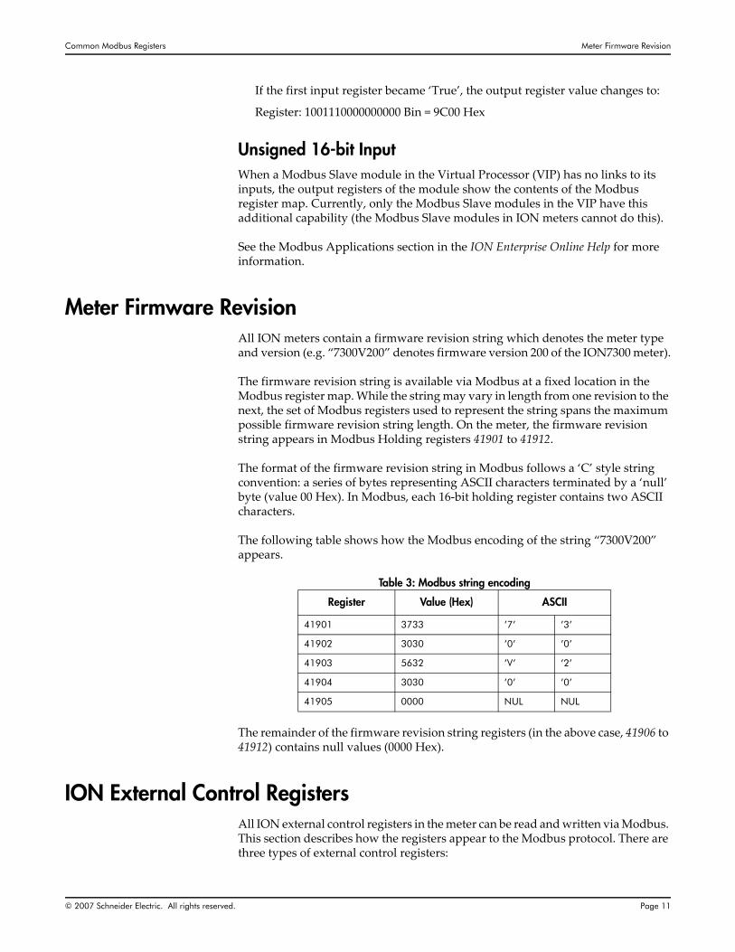
Meter Firmware RevisionAll ION meters contain a firmware revision string which denotes the meter type and version (e.g. “7300V200” denotes firmware version 200 of the ION7300 meter).
The firmware revision string is available via Modbus at a fixed location in the Modbus register map. While the string may vary in length from one revision to the next, the set of Modbus registers used to represent the string spans the maximum possible firmware revision string length. On the meter, the firmware revision string appears in Modbus Holding registers 41901 to 41912.
The format of the firmware revision string in Modbus follows a ‘C’ style string convention: a series of bytes representing ASCII characters terminated by a ‘null’ byte (value 00 Hex). In Modbus, each 16‐bit holding register contains two ASCII characters.
The following table shows how the Modbus encoding of the string “7300V200” appears.
Table 3: Modbus string encoding
The remainder of the firmware revision string registers (in the above case, 41906 to 41912) contains null values (0000 Hex).
ION External Control RegistersAll ION external control registers in the meter can be read and written via Modbus. This section describes how the registers appear to the Modbus protocol. There are three types of external control registers:
Register Value (Hex) ASCII
41901 3733 ’7’ ’3’
41902 3030 ’0’ ’0’
41903 5632 ’V’ ’2’
41904 3030 ’0’ ’0’
41905 0000 NUL NUL
ION External Control Registers Common Modbus Registers
Page 12 © 2007 Schneider Electric. All rights reserved.
External Pulse Control Registers
External Boolean Control Registers
External Numeric Control Registers
For a complete Modbus external control register map, see the ION 7300 Series Meter Modbus Protocol document (Appendix E), available from the website.
External Pulse RegistersExternal Pulse registers interface to manually triggering events in the meter. For example, they can reset counters or timers, or pulse external equipment. All of the meter external pulse registers are available via Modbus.
Pulse registers are meaningful mainly for writing. Writing a nonzero value to a pulse register causes a pulse. Writing a zero value has no effect, but is acknowledged as a successful write operation. This feature provides the capability to ‘skip’ triggers when pulsing multiple registers in one request.
The meter’s External Pulse registers are located in the Modbus register map starting at 42001.
Example:
A meter is pre‐configured with external pulse modules. See your meter’s User Guide for more information.
The Modbus master requests to reset Min/Max, SWD, TD, and Integrators. The outgoing write request is to write 7 registers, starting at 42001, with values 1, 0, 1, 1, 0, 0, and 1.
External Boolean RegistersION External Boolean registers provide an interface to manually turn a signal ON or OFF. For example, these registers can enable or disable ION modules. The functionality depends on the meter configuration.
A value of one (1) for a Boolean register represents ‘ON’ or ‘TRUE’. A value of zero (0) represents ‘OFF’ or ‘FALSE’. Writing a value other than zero or one results in the value of one.
The meter’s External Boolean registers are located in the Modbus register map starting at 42201.
External Numeric RegistersExternal Numeric registers can be set to a certain value. See your meter’s User Guide and the ION Reference for an example of how and where these registers can be used.
The External Numeric registers are 32‐bit values represented in 32‐bit Signed Integer Format (see “32‐bit Integer Format” on page 9). Each External Numeric register spans two 16‐bit Modbus registers. The first Modbus register of the pair

Common Modbus Registers Enumerated ION Module Setup Registers
© 2007 Schneider Electric. All rights reserved. Page 13
represents the high order word of the 32‐bit value. The second Modbus register represents the low order word. The 32‐bit value read from or written to an External Numeric register via Modbus is represented as a 32‐bit signed integer value, therefore the range of possible values is ‐2,147,483,648 to +2,147,483,647.
The meter’s External Numeric registers are located in the Modbus register map starting at 42301.
Enumerated ION Module Setup RegistersThe Enumerated setup register is a major class of setup registers in ION modules. Enumerated registers are used where there is a list of options to choose from.
In Modbus protocol, Enumerated register lists are represented by a numeric relationship. For example, with the Power Meter module Volts Mode register, the following relationship is defined:
0 = 4W‐WYE1 = DELTA2 = SINGLE3 = DEMO4 = 3W‐WYE5 = DIRECT‐DELTA
Not all Enumerated ION module setup registers on the meter are included in the Modbus register map. The register map details how enumerations are represented numerically in Modbus for each register.
Numeric Bounded ION Module Setup RegistersThe Numeric Bounded setup register is another major class of setup registers in ION modules. Examples of numeric bounded setup registers include Power Meter module PT/CT Ratios, Communications module Unit ID, etc.
Numeric Bounded registers are represented in Modbus in Signed 32‐bit Integer Format (see “32‐bit Integer Format” on page 9), where each ION Numeric Bounded register spans two 16‐bit Modbus registers. Because of the Modbus register format, an absolute boundary of ‐2,147,483,648 to +2,147,483,647 is imposed on Numeric Bounded ION module setup registers. Even if the ION register bounds are beyond the 32‐bit signed integer boundary, the bounds are effectively limited by Modbus capabilities.
All Numeric Bounded ION module setup registers on the meter are included in the Modbus register map. The register map details the numeric bounds in Modbus for each register.
Like Enumerated ION module setup registers, Numeric Bounded setup registers are located in the Modbus register map in order of ION handles.

Modbus Configuration Common Modbus Registers
Page 14 © 2007 Schneider Electric. All rights reserved.
Modbus ConfigurationModbus on the meter is configurable in two components:
Protocol Configuration (Communications module)
Register Configuration (Modbus Slave module)
See the ION Reference for full descriptions of the Communications and Modbus Slave modules.
Modbus Protocol Configuration (Communications Module)The meter Communications module stores all setup information that applies to a protocol on a communications port. Setup registers in this module store both the protocol selected and all setup parameters for that protocol.
The setup registers for the Communications modules on the meter are accessible via Modbus as fixed‐location readable and writable registers.
0
These registers are explained in the following sections.
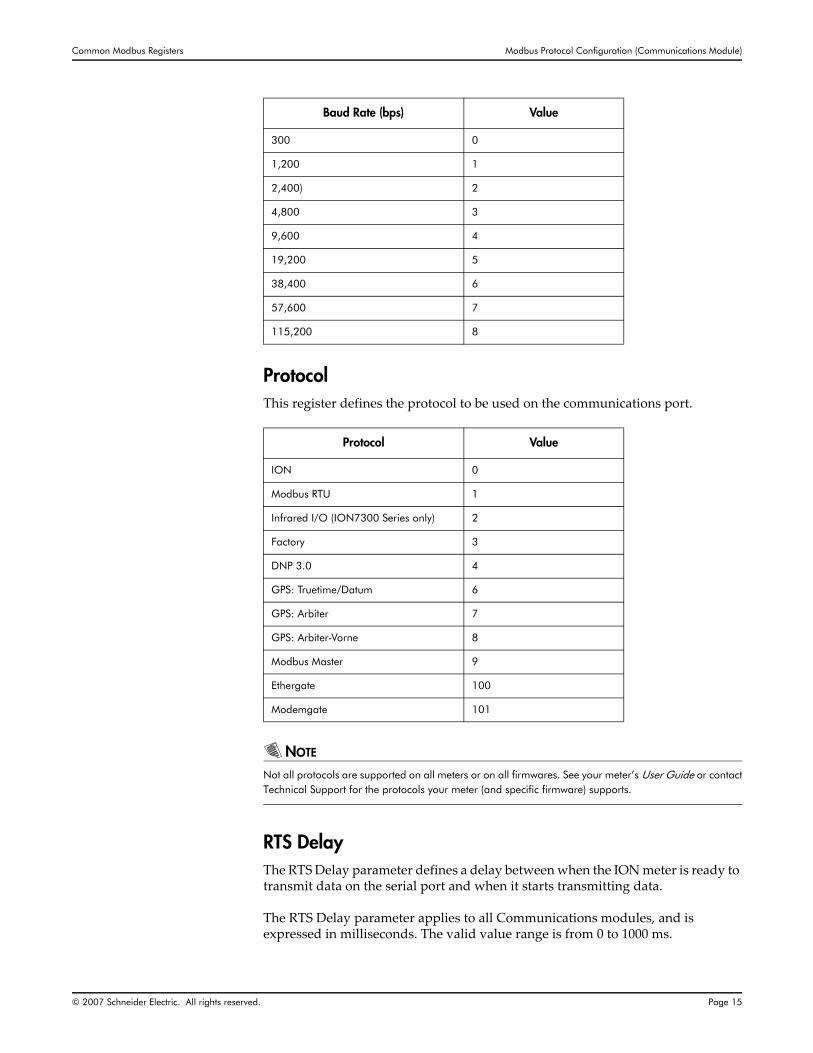
Baud RateEach Communications module on the meter has a Baud Rate register, which specifies the speed of serial communications. The following values apply to all Communications modules:
SETUP REGISTER MODBUS REGISTER(S)
COM1 Baud Rate 44392
COM1 Protocol 44592
COM1 RTS Delay 46977 to 46978
COM1 Unit ID 46979 to 46980
COM2 Baud Rate 44590
COM2 Protocol 44593
COM2 RTS Delay 47125 to 47126
COM2 Unit ID 47129 to 47130
COM3 Baud Rate 44591
COM3 Protocol 44594
COM3 Unit ID 47131 to 47132
COM4 Protocol 45461
Common Modbus Registers Modbus Protocol Configuration (Communications Module)
© 2007 Schneider Electric. All rights reserved. Page 15
ProtocolThis register defines the protocol to be used on the communications port.
NOTE
Not all protocols are supported on all meters or on all firmwares. See your meter’s User Guide or contactTechnical Support for the protocols your meter (and specific firmware) supports.
RTS DelayThe RTS Delay parameter defines a delay between when the ION meter is ready to transmit data on the serial port and when it starts transmitting data.
The RTS Delay parameter applies to all Communications modules, and is expressed in milliseconds. The valid value range is from 0 to 1000 ms.
Baud Rate (bps) Value
300 0
1,200 1
2,400) 2
4,800 3
9,600 4
19,200 5
38,400 6
57,600 7
115,200 8
Protocol Value
ION 0
Modbus RTU 1
Infrared I/O (ION7300 Series only) 2
Factory 3
DNP 3.0 4
GPS: Truetime/Datum 6
GPS: Arbiter 7
GPS: Arbiter-Vorne 8
Modbus Master 9
Ethergate 100
Modemgate 101

CRC-16 Calculation Common Modbus Registers
Page 16 © 2007 Schneider Electric. All rights reserved.
Unit IDThe Unit ID register defines the slave address for the protocol being used on the communications port.
In Modbus protocol, the Unit ID parameter defines the slave address used in Modbus packets for the device in question.
Since this parameter applies to both ION and Modbus protocols, the valid range for the parameter is defined to fit both protocols. Thus the range is specified as 1 to 9999. However, since the slave address range specified for Modbus is smaller than that of the Unit ID setup register, the valid range of this parameter is limited to 1 to 247.
CRC-16 CalculationThis section describes the procedure for obtaining the CRC‐16 error check field for a Modbus RTU frame.
ProcedureA frame can be considered as a continuous, serial stream of binary data (ones and zeros). The 16‐bit checksum is obtained by multiplying the serial data stream by 216 (10000000000000000) and then dividing it by the generator polynomial x16+x15+x2+1, which can be expressed as the 16‐bit binary number 11000000000000101. The quotient is ignored and the 16‐bit remainder is the checksum, which is appended to the end of the frame.
In calculating the CRC, all arithmetic operations (additions and subtractions) are performed using MODULO TWO, or EXCLUSIVE OR operation. A step‐by‐step example shows how to obtain the checksum for a simple Modbus RTU frame.
Steps for generating the CRC‐16 checksum:
1. Drop the MSB (Most Significant Bit) of the generator polynomial and reverse the bit sequence to form a new polynomial. This yields the binary number 1010 0000 0000 0001, or A0 01 (hex).
2. Load a 16‐bit register with initial value FF FF (hex).
3. Exclusive OR the first data byte with the low‐order byte of the 16‐bit register. Store the result in the 16‐bit register.
4. Shift the 16‐bit register one bit to the right.
5. If the bit shifted out to the right is one, Exclusive OR the 16‐bit register with the new generator polynomial, store the result in the 16‐bit registers. Return to step 4.
6. If the bit shifted out to the right is zero, return to step 4.
7. Repeat steps 4 and 5 until 8 shifts have been performed.
8. Exclusive OR the next data byte with the 16‐bit register.
Common Modbus Registers CRC-16 Calculation
© 2007 Schneider Electric. All rights reserved. Page 17
9. Repeat steps 4 through 7 until all bytes of the frame are Exclusive OR’ed with the 16‐bit register and shifted 8 times.
10. The content of the 16‐bit register is the checksum and is appended to the end of the frame.
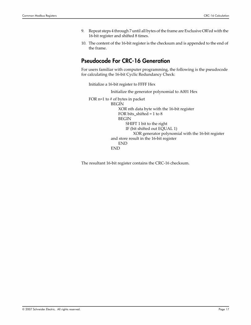
Pseudocode For CRC-16 GenerationFor users familiar with computer programming, the following is the pseudocode for calculating the 16‐bit Cyclic Redundancy Check:
Initialize a 16‐bit register to FFFF Hex
Initialize the generator polynomial to A001 Hex
FOR n=1 to # of bytes in packetBEGIN
XOR nth data byte with the 16‐bit registerFOR bits_shifted = 1 to 8BEGIN
SHIFT 1 bit to the rightIF (bit shifted out EQUAL 1)
XOR generator polynomial with the 16‐bit register and store result in the 16‐bit register
ENDEND
The resultant 16‐bit register contains the CRC‐16 checksum.

Modbus Register Configuration (Modbus Slave Module) Common Modbus Registers
Page 18 © 2007 Schneider Electric. All rights reserved.
Modbus Register Configuration (Modbus Slave Module)The ION Modbus Slave module provides a configurable interface to export ION data to the Modbus protocol.
The Modbus Slave module is configurable in two ways:
ION Registers are ‘linked’ to the module
the Modbus Slave module setup is altered
The first type of configuration is beyond the scope of the Modbus protocol. The meter comes with a set of default linkages for Modbus Slave modules that suit a wide range of applications. For more information on your meter’s specific default Modbus Slave modules, see your meter’s User Guide.
The second type of Modbus Slave module configuration is accomplished via the meter display, the ION protocol, or the Modbus protocol.
The setup registers for the Modbus Slave modules on the meter are available via Modbus for control and interrogation. See “Common Modbus Registers” on page 26 for details of these Modbus registers.
FormatModbus Slave modules can export ION data to Modbus Holding registers in a variety of formats. These formats are selectable via the Format setup register of the Modbus Slave module. The following values are valid Format selections:
0 = Unsigned 16B1 = Signed 16B2 = Unsigned 32B3 = Signed 32B4 = Unsigned 32B‐M10K5 = Signed 32B‐M10K6 = Packed Boolean7 = Unsigned 16B Input Mode
BaseAddrThe BaseAddr setup register defines the starting Modbus register address to which the Modbus Slave module exports ION data. The valid range for this setup register is 40001 to 41800.
ScalingThe Modbus Slave module can scale and offset input values to fit within the output range for the selected format. The Scaling setup register selects if scaling (as defined by InZero, InFull, OutZero, and OutFull) is applied to the inputs. The following values are valid for the Scaling setup register:
0 = No
1 = Yes

Common Modbus Registers Modbus Register Configuration (Modbus Slave Module)
© 2007 Schneider Electric. All rights reserved. Page 19
InZero, InFullIf Scaling is set to YES for a Modbus Slave module, the input values are scaled according to a formula derived partly from the InZero, InFull setup registers. Input values falling at or below InZero are represented as OutZero. Input values falling at or above InFull are represented as OutFull. Input values between InZero and InFull are represented as a proportionate value between OutZero and OutFull.
InZero and InFull are defined to range from ‐1x1038 to +1x1038, but via Modbus, these registers are represented in Signed 32‐bit Integer format, so the integer bounds of ‐2,147,483,648 to +2,147,483,647 are imposed upon these registers.
OutZero, OutFullIf Scaling is set to YES, the input values to the Modbus Slave module are scaled by a formula derived partly from OutZero, OutFull. The absolute range of these registers is ‐2,147,483,647 to +2,147,483,647, but the valid range varies depending on the selected Format for the Modbus Slave module. The following chart shows the OutZero, OutFull ranges for the various Formats:
Table 6: Out Zero and Out Full ranges for Modbus formats
Format Low Bound High Bound
Unsigned 16B 0 +65535
Signed 16B -32767 +32767
Unsigned 32B 0 +2,147,478,647
Signed 32B -2,147,478,647 +2,147,478,647
Unsigned 32B-M10K 0 +65,535,999
Signed 32B-M10K -32,767,999 +32,767,999
Packed Boolean N/A N/A

Data Record / Modbus Map Common Modbus Registers
Page 20 © 2007 Schneider Electric. All rights reserved.
Data Record / Modbus MapThis section contains the Data Record/Modbus register map for ION meters.
Modbus Data Recorder RegistersION meters provide data from Data Recorder modules to be exported into Modbus Registers. The Register Map is a dynamic map and dependent on the configuration of Data Recorder Source inputs. See the ION Reference for a description of Data Recorder modules.
Modbus Data Recorder Map
Modbus Data Recorder RetrievalTo retrieve Data Record via Modbus communications the following steps must be followed:
1. Ensure the Data Recorder is online.
2. Write the Data Recorder module Number to Modbus Register 43001. If an invalid Data Recorder module Number is written, a Modbus Exception is returned.
3. Determine a valid Starting Record with a Read of Modbus Registers 43001 through 43011. This returns the Modbus Record Availability and Selection. All valid Record Numbers lie in the range of the Oldest Record Number (Modbus Registers 43008 and 43009) and the Newest Record Number (Modbus Registers 43010 and 43011).
4. After a valid Record Number is determined write it to Modbus Registers 43002 and 43003 (Master’s Request for Starting Record) so a valid data is cached and read back.
5. A Read returns the data for each available record starting at record number written to Modbus Registers 43002 and 43003. The number of records returned depends on the number of Source Inputs connected to the Data Recorder and the number of records available with respect to the Start Record.
6. Repeat steps 3 through 6 for new records.
NOTE
All data is cached and can be read back at any time until a new write is requested. Any setup changes inthe Data Recorder module clears all cached Data Records.
Modbus Register Contents
43001 to 43011 Record Availability and Selection Block
43012 to 43125 Data Record Block
43126 to 43137 Reserved Registers
43138 to 43153 Source Input Handle ID

Common Modbus Registers Data Record / Modbus Map
© 2007 Schneider Electric. All rights reserved. Page 21
Modbus Record Availability and Selection Block Registers
Modbus registers 43001 through 43011 contain the Data Recorder Record information necessary to retrieve valid records. A valid Data Recorder module Number must be written to Modbus Register 43001 prior to reading any Modbus Data Recorder Registers, otherwise a Modbus exception will be returned.
Modbus Data Record Block RegistersModbus registers 43012 through 43125 contain the Record Number, Time Stamp, and Source Input Data for each record retrieved. This Modbus mapping is dynamic, dependant on the number of source inputs connected to the Data Recorder module.
The Record Number is returned as an unsigned 32‐bit value stored in two Modbus registers. The first register is the high order followed by the low order second register.
Modbus Register
# of Modbus Registers
Description Format Properties
43001 1Data Recorder module Number - write to this register with the data recorder module number you want to access.
UINT16 Read / Write
43002, 43003 2
Master’s Request for Starting Record - write to these registers with the starting record number. Write the high order word to register 43002 and the low order word to register 43003.
UINT32 Read / Write
43004 1Number of Source Inputs - read this register to return the number of source input connected to the data recorder module (register 43001).
UINT16 Read
43005 1Module Setup Count - read this register to return the module setup count. A change in the module setup count reflects a change in the data recorder module setup.
UINT16 Read
43006 1Maximum Number of Records / Request - read this register to return the maximum number of records per request.
UINT16 Read
43007 1Number of Available Records / Request - read this register to return the number of available record per request.
UINT16 Read
43008, 43009 2
Oldest Record Number - read these registers to return the oldest available record number. Register 43008 returns the high order word and register 43009 returns the low order word.
UINT32 Read
43010, 43011 2
Newest Record Number - read these registers to return the newest available record number. Register 43010 returns the high order word and register 43011 return the low order word.
UINT32 Read

Data Record / Modbus Map Common Modbus Registers
Page 22 © 2007 Schneider Electric. All rights reserved.
The Time Stamp Seconds is returned as an unsigned 32‐bit value stored in two Modbus registers. The first register is the high order followed by the low order second register. The format is UNIX time (UTC). See the ION Reference for a description of the Clock module time format.
The Time Stamp MicroSeconds is returned as an unsigned 32‐bit value stored in two Modbus registers. The first register is the high order followed by the low order second register. The format is absolute time in micro seconds.
The Source Input Data is returned as a Float value stored in two Modbus registers. The first register is the high order followed by the low order second register. The format is IEEE‐754.
The following is an example of a Data Recorder module with one source input connected (14 records maximum):
Modbus Register
# of Modbus Registers Description Format Properties
43012 2 Record Number (x) UINT32 Read
43014 2 UTC Seconds UINT32 Read
43016 2 UTC MicroSeconds UINT32 Read
43018 2 Source 1 Input Data FLOAT Read
43020 2 Record Number (x+1) UINT32 Read
43022 2 UTC Seconds UINT32 Read
43024 2 UTC MicroSeconds UINT32 Read
43026 2 Source 1 Input Data FLOAT Read
43116 2 Record Number (x+13) UINT32 Read
43118 2 UTC Seconds UINT32 Read
43120 2 UTC MicroSeconds UINT32 Read
43122 2 Source 1 Input Data FLOAT Read

Common Modbus Registers Data Record / Modbus Map
© 2007 Schneider Electric. All rights reserved. Page 23
The following is an example of a Data Recorder module with 16 source inputs connected (3 records maximum):
Modbus Register # of Modbus Registers Description Format Properties
43012 2 Record Number (x) UINT32 Read
43014 2 UTC Seconds UINT32 Read
43016 2 UTC MicroSeconds UINT32 Read
43018 2 Source 1 Input Data FLOAT Read
43020 2 Source 2 Input Data FLOAT Read
43022 2 Source 3 Input Data FLOAT Read
43024 2 Source 4 Input Data FLOAT Read
43026 2 Source 5 Input Data FLOAT Read
43028 2 Source 6 Input Data FLOAT Read
43030 2 Source 7 Input Data FLOAT Read
43032 2 Source 8 Input Data FLOAT Read
43034 2 Source 9 Input Data FLOAT Read
43036 2 Source 10 Input Data FLOAT Read
43038 2 Source 11 Input Data FLOAT Read
43040 2 Source 12 Input Data FLOAT Read
43042 2 Source 13 Input Data FLOAT Read
43044 2 Source 14 Input Data FLOAT Read
43046 2 Source 15 Input Data FLOAT Read
43048 2 Source 16 Input Data FLOAT Read
43088 2 Record Number (x+2) UINT32 Read
43090 2 UTC Seconds UINT32 Read
43092 2 UTC MicroSeconds UINT32 Read
43094 2 Source 1 Input Data FLOAT Read
43096 2 Source 2 Input Data FLOAT Read
43098 2 Source 3 Input Data FLOAT Read
43100 2 Source 4 Input Data FLOAT Read
43102 2 Source 5 Input Data FLOAT Read
43104 2 Source 6 Input Data FLOAT Read
43106 2 Source 7 Input Data FLOAT Read
43108 2 Source 8 Input Data FLOAT Read
43110 2 Source 9 Input Data FLOAT Read
43112 2 Source 10 Input Data FLOAT Read
43114 2 Source 11 Input Data FLOAT Read
43116 2 Source 12 Input Data FLOAT Read
43118 2 Source 13 Input Data FLOAT Read
43120 2 Source 14 Input Data FLOAT Read

Data Record / Modbus Map Common Modbus Registers
Page 24 © 2007 Schneider Electric. All rights reserved.
Modbus Handle ID RegistersModbus registers 43138 through 43153 contain the Handle ID’s for the Source Inputs.
43122 2 Source 15 Input Data FLOAT Read
43124 2 Source 16 Input Data FLOAT Read
Modbus Register # of Modbus Registers Description Format Properties
Modbus Register # of Modbus Registers Description Format Properties
43138 1 Source 1 Handle ID UINT16 Read
43139 1 Source 2 Handle ID UINT16 Read
43140 1 Source 3 Handle ID UINT16 Read
43141 1 Source 4 Handle ID UINT16 Read
43142 1 Source 5 Handle ID UINT16 Read
43143 1 Source 6 Handle ID UINT16 Read
43144 1 Source 7 Handle ID UINT16 Read
43145 1 Source 8 Handle ID UINT16 Read
43146 1 Source 9 Handle ID UINT16 Read
43147 1 Source 10 Handle ID UINT16 Read
43148 1 Source 11 Handle ID UINT16 Read
43149 1 Source 12 Handle ID UINT16 Read
43150 1 Source 13 Handle ID UINT16 Read
43151 1 Source 14 Handle ID UINT16 Read
43152 1 Source 15 Handle ID UINT16 Read
43153 1 Source 16 Handle ID UINT16 Read

Common Modbus Registers Modbus Meter Time Set
© 2007 Schneider Electric. All rights reserved. Page 25
Modbus Meter Time SetThis section contains the Modbus Meter UNIX Time Set function of ION meters.
Modbus Meter Time SetUnix Time (UTC) Seconds is an unsigned 32‐bit value stored in two Modbus registers. The first register is the high order followed by the low order second register. See the ION Reference for a description of the Clock module time format.
UTC microseconds is an unsigned 32‐bit value stored in two Modbus registers. The first register is the high order followed by the low order second register. The format is absolute time in MicroSeconds.
Only resolution by seconds is supported when setting Meter Time via Modbus.
Modbus Time SetTo set the Meter time via Modbus communications, do the following:
1. Set the ION Clock module Time Sync Source register to the Modbus communications port.
2. Write the UNIX time in seconds as an unsigned 32‐bit value to Modbus Registers 41926 (high order) and 41927 (low order).
Modbus Register # of Modbus Registers Description Format Properties
41926 2 UTC Seconds UINT32 Read / Write
41928 2 UTC microseconds UINT32 Read

Common Modbus Registers Common Modbus Registers
Page 26 © 2007 Schneider Electric. All rights reserved.
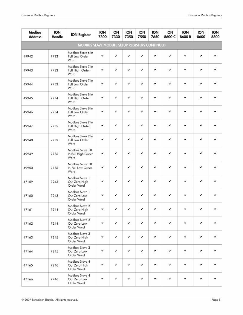
Common Modbus RegistersThe following table provides ION to Modbus mappings for many of the commonly used registers. A check mark signifies that the meter supports that register. For a complete map for your device, see the website.
Modbus Address
ION Handle ION Register ION
7300ION 7330
ION 7350
ION 7550
ION 7650
ION 8600 C
ION 8600 B
ION 8600
ION 8800
MODBUS SLAVE MODULE OUTPUT REGISTERS
40001 to 41831 N/ARefer to your meter’s User Guide for details.
a a a a a a a a a
MODBUS SLAVE MODULE SETUP REGISTERS
44596 7A53 Modbus Slave 1 Format see note 1 a a a a a a a a a
44597 7A54 Modbus Slave 2 Format see note 1 a a a a a a a a a
44598 7A55 Modbus Slave 3 Format see note 1 a a a a a a a a a
44599 7A56 Modbus Slave 4 Format see note 1 a a a a a a a a a
45196 7CAB Modbus Slave 5 Format see note 1 a a a a a a a a a
45197 7CAC Modbus Slave 6 Format see note 1 a a a a a a a a a
45198 7CAD Modbus Slave 7 Format see note 1 a a a a a a a a a
45199 7CAE Modbus Slave 8 Format see note 1 a a a a a a a a a
45200 7CAF Modbus Slave 9 Format see note 1 a a a a a a a a a
45201 7CB0 Modbus Slave 10 Format see note 1 a a a a a a a a a
45618 7E51 Modbus Slave 11 Format see note 1 a a a a a a a a a
45619 7E52 Modbus Slave 12 Format see note 1 a a a a a a a a a
45620 7E53Modbus Slave 13 Format see note 1 a a a a a a a a a
45621 7E54Modbus Slave 14 Format see note 1 a a a a a a a a a
45622 7E55Modbus Slave 15 Format see note 1 a a a a a a a a a
45623 7E56Modbus Slave 16 Format see note 1 a a a a a a a a a
45624 7E57Modbus Slave 17 Format see note 1 a a a a a a a a a

Common Modbus Registers Common Modbus Registers
© 2007 Schneider Electric. All rights reserved. Page 27
MODBUS SLAVE MODULE SETUP REGISTERS CONTINUED
45625 7E58Modbus Slave 18 Format see note 1 a a a a a a a a a
45626 7E59Modbus Slave 19 Format see note 1 a a a a a a a a a
45627 7E5AModbus Slave 20 Format see note 1 a a a a a a a a a
44600 7A57Modbus Slave 1 Scaling see note 2 a a a a a a a a a
44601 7A58Modbus Slave 2 Scaling see note 2 a a a a a a a a a
44602 7A59Modbus Slave 3 Scaling see note 2 a a a a a a a a a
44603 7A5AModbus Slave 4 Scaling see note 2 a a a a a a a a a
45202 7CB1Modbus Slave 5 Scaling see note 2 a a a a a a a a a
45203 7CB2 Modbus Slave 6 Scaling see note 2 a a a a a a a a a
45204 7CB3 Modbus Slave 7 Scaling see note 2 a a a a a a a a a
45205 7CB4 Modbus Slave 8 Scaling see note 2 a a a a a a a a a
45206 7CB5 Modbus Slave 9 Scaling see note 2 a a a a a a a a a
45207 7CB6 Modbus Slave 10 Scaling see note 2 a a a a a a a a a
45628 7E5B Modbus Slave 11 Scaling see note 2 a a a a a a a a a
45629 7E5C Modbus Slave 12 Scaling see note 2 a a a a a a a a a
45630 7E5D Modbus Slave 13 Scaling see note 2 a a a a a a a a a
45631 7E5E Modbus Slave 14 Scaling see note 2 a a a a a a a a a
45632 7E5F Modbus Slave 15 Scaling see note 2 a a a a a a a a a
45633 7E60 Modbus Slave 16 Scaling see note 2 a a a a a a a a a
45634 7E61 Modbus Slave 17 Scaling see note 2 a a a a a a a a a
45635 7E62 Modbus Slave 18 Scaling see note 2 a a a a a a a a a
45636 7E63 Modbus Slave 19 Scaling see note 2 a a a a a a a a a
45637 7E64 Modbus Slave 20 Scaling see note 2 a a a a a a a a a
Modbus Address
ION Handle ION Register ION
7300ION 7330
ION 7350
ION 7550
ION 7650
ION 8600 C
ION 8600 B
ION 8600
ION 8800

Common Modbus Registers Common Modbus Registers
Page 28 © 2007 Schneider Electric. All rights reserved.
MODBUS SLAVE MODULE SETUP REGISTERS CONTINUED
47135 7237Modbus Slave 1 Base Address High Order Word
a a a a a a a a a
47136 7237Modbus Slave 1 Base Address Low Order Word
a a a a a a a a a
47137 7238Modbus Slave 2 Base Address High Order Word
a a a a a a a a a
47138 7238Modbus Slave 2 Base Address Low Order Word
a a a a a a a a a
47139 7239Modbus Slave 3 Base Address High Order Word
a a a a a a a a a
47140 7239Modbus Slave 3 Base Address Low Order Word
a a a a a a a a a
47141 723AModbus Slave 4 Base Address High Order Word
a a a a a a a a a
47142 723AModbus Slave 4 Base Address Low Order Word
a a a a a a a a a
49915 77A5Modbus Slave 5 Base Address High Order Word
a a a a a a a a a
49916 77A5Modbus Slave 5 Base Address Low Order Word
a a a a a a a a a
49917 77A6Modbus Slave 6 Base Address High Order Word
a a a a a a a a a
49918 77A6Modbus Slave 6 Base Address Low Order Word
a a a a a a a a a
49919 77A7Modbus Slave 7 Base Address High Order Word
a a a a a a a a a
49920 77A7Modbus Slave 7 Base Address Low Order Word
a a a a a a a a a
49921 77A8Modbus Slave 8 Base Address High Order Word
a a a a a a a a a
49922 77A8Modbus Slave 8 Base Address Low Order Word
a a a a a a a a a
49923 77A9Modbus Slave 9 Base Address High Order Word
a a a a a a a a a
Modbus Address
ION Handle ION Register ION
7300ION 7330
ION 7350
ION 7550
ION 7650
ION 8600 C
ION 8600 B
ION 8600
ION 8800

Common Modbus Registers Common Modbus Registers
© 2007 Schneider Electric. All rights reserved. Page 29
MODBUS SLAVE MODULE SETUP REGISTERS CONTINUED
49924 77A9Modbus Slave 9 Base Address Low Order Word
a a a a a a a a a
49925 77AAModbus Slave 10 Base Address High Order Word
a a a a a a a a a
49926 77AAModbus Slave 10 Base Address Low Order Word
a a a a a a a a a
47143 723BModbus Slave 1 In Zero High Order Word
a a a a a a a a a
47144 723BModbus Slave 1 In Zero Low Order Word
a a a a a a a a a
47145 723CModbus Slave 2 In Zero High Order Word
a a a a a a a a a
47146 723CModbus Slave 2 In Zero Low Order Word
a a a a a a a a a
47147 723DModbus Slave 3 In Zero High Order Word
a a a a a a a a a
47148 723DModbus Slave 3 In Zero Low Order Word
a a a a a a a a a
47149 723EModbus Slave 4 In Zero High Order Word
a a a a a a a a a
47150 723EModbus Slave 4 In Zero Low Order Word
a a a a a a a a a
49927 77ABModbus Slave 5 In Zero High Order Word
a a a a a a a a a
49928 77ABModbus Slave 5 In Zero Low Order Word
a a a a a a a a a
49929 77ACModbus Slave 6 In Zero High Order Word
a a a a a a a a a
49930 77ACModbus Slave 6 In Zero Low Order Word
a a a a a a a a a
49931 77ADModbus Slave 7 In Zero High Order Word
a a a a a a a a a
49932 77ADModbus Slave 7 In Zero Low Order Word
a a a a a a a a a
Modbus Address
ION Handle ION Register ION
7300ION 7330
ION 7350
ION 7550
ION 7650
ION 8600 C
ION 8600 B
ION 8600
ION 8800

Common Modbus Registers Common Modbus Registers
Page 30 © 2007 Schneider Electric. All rights reserved.
MODBUS SLAVE MODULE SETUP REGISTERS CONTINUED
49933 77AEModbus Slave 8 In Zero High Order Word
a a a a a a a a a
49934 77AEModbus Slave 8 In Zero Low Order Word
a a a a a a a a a
49935 77AFModbus Slave 9 In Zero High Order Word
a a a a a a a a a
49936 77AFModbus Slave 9 In Zero Low Order Word
a a a a a a a a a
49937 77B0Modbus Slave 10 In Zero High Order Word
a a a a a a a a a
49938 77B0Modbus Slave 10 In Zero Low Order Word
a a a a a a a a a
47151 723FModbus Slave 1 In Full High Order Word
a a a a a a a a a
47152 723FModbus Slave 1 In Full Low Order Word
a a a a a a a a a
47153 7240Modbus Slave 2 In Full High Order Word
a a a a a a a a a
47154 7240Modbus Slave 2 In Full Low Order Word
a a a a a a a a a
47155 7241Modbus Slave 3 In Full High Order Word
a a a a a a a a a
47156 7241Modbus Slave 3 In Full Low Order Word
a a a a a a a a a
47157 7242Modbus Slave 4 In Full High Order Word
a a a a a a a a a
47158 7242Modbus Slave 4 In Full Low Order Word
a a a a a a a a a
49939 77B1Modbus Slave 5 In Full High Order Word
a a a a a a a a a
49940 77B1Modbus Slave 5 In Full Low Order Word
a a a a a a a a a
49941 77B2Modbus Slave 6 In Full High Order Word
a a a a a a a a a
Modbus Address
ION Handle ION Register ION
7300ION 7330
ION 7350
ION 7550
ION 7650
ION 8600 C
ION 8600 B
ION 8600
ION 8800
Common Modbus Registers Common Modbus Registers
© 2007 Schneider Electric. All rights reserved. Page 31
MODBUS SLAVE MODULE SETUP REGISTERS CONTINUED
49942 77B2Modbus Slave 6 In Full Low Order Word
a a a a a a a a a
49943 77B3Modbus Slave 7 In Full High Order Word
a a a a a a a a a
49944 77B3Modbus Slave 7 In Full Low Order Word
a a a a a a a a a
49945 77B4Modbus Slave 8 In Full High Order Word
a a a a a a a a a
49946 77B4Modbus Slave 8 In Full Low Order Word
a a a a a a a a a
49947 77B5Modbus Slave 9 In Full High Order Word
a a a a a a a a a
49948 77B5Modbus Slave 9 In Full Low Order Word
a a a a a a a a a
49949 77B6Modbus Slave 10 In Full High Order Word
a a a a a a a a a
49950 77B6Modbus Slave 10 In Full Low Order Word
a a a a a a a a a
47159 7243Modbus Slave 1 Out Zero High Order Word
a a a a a a a a a
47160 7243Modbus Slave 1 Out Zero Low Order Word
a a a a a a a a a
47161 7244Modbus Slave 2 Out Zero High Order Word
a a a a a a a a a
47162 7244Modbus Slave 2 Out Zero Low Order Word
a a a a a a a a a
47163 7245Modbus Slave 3 Out Zero High Order Word
a a a a a a a a a
47164 7245Modbus Slave 3 Out Zero Low Order Word
a a a a a a a a a
47165 7246Modbus Slave 4 Out Zero High Order Word
a a a a a a a a a
47166 7246Modbus Slave 4 Out Zero Low Order Word
a a a a a a a a a
Modbus Address
ION Handle ION Register ION
7300ION 7330
ION 7350
ION 7550
ION 7650
ION 8600 C
ION 8600 B
ION 8600
ION 8800

Common Modbus Registers Common Modbus Registers
Page 32 © 2007 Schneider Electric. All rights reserved.
MODBUS SLAVE MODULE SETUP REGISTERS CONTINUED
49951 77B7Modbus Slave 5 Out Zero High Order Word
a a a a a a a a a
49952 77B7Modbus Slave 5 Out Zero Low Order Word
a a a a a a a a a
49953 77B8Modbus Slave 6 Out Zero High Order Word
a a a a a a a a a
49954 77B8Modbus Slave 6 Out Zero Low Order Word
a a a a a a a a a
49955 77B9Modbus Slave 7 Out Zero High Order Word
a a a a a a a a a
49956 77B9Modbus Slave 7 Out Zero Low Order Word
a a a a a a a a a
49957 77BAModbus Slave 8 Out Zero High Order Word
a a a a a a a a a
49958 77BAModbus Slave 8 Out Zero Low Order Word
a a a a a a a a a
49959 77BBModbus Slave 9 Out Zero High Order Word
a a a a a a a a a
49960 77BBModbus Slave 9 Out Zero Low Order Word
a a a a a a a a a
49961 77BCModbus Slave 10 Out Zero High Order Word
a a a a a a a a a
49962 77BCModbus Slave 10 Out Zero Low Order Word
a a a a a a a a a
47167 7247Modbus Slave 1 Out Full High Order Word
a a a a a a a a a
47168 7247Modbus Slave 1 Out Full Low Order Word
a a a a a a a a a
47169 7248Modbus Slave 2 Out Full High Order Word
a a a a a a a a a
47170 7248Modbus Slave 2 Out Full Low Order Word
a a a a a a a a a
47171 7249Modbus Slave 3 Out Full High Order Word
a a a a a a a a a
Modbus Address
ION Handle ION Register ION
7300ION 7330
ION 7350
ION 7550
ION 7650
ION 8600 C
ION 8600 B
ION 8600
ION 8800

Common Modbus Registers Common Modbus Registers
© 2007 Schneider Electric. All rights reserved. Page 33
MODBUS SLAVE MODULE SETUP REGISTERS CONTINUED
47172 7249Modbus Slave 3 Out Full Low Order Word
a a a a a a a a a
47173 724AModbus Slave 4 Out Full High Order Word
a a a a a a a a a
47174 724AModbus Slave 4 Out Full Low Order Word
a a a a a a a a a
49963 77BDModbus Slave 5 Out Full High Order Word
a a a a a a a a a
49964 77BDModbus Slave 5 Out Full Low Order Word
a a a a a a a a a
49965 77BEModbus Slave 6 Out Full High Order Word
a a a a a a a a a
49966 77BEModbus Slave 6 Out Full Low Order Word
a a a a a a a a a
49967 77BFModbus Slave 7 Out Full High Order Word
a a a a a a a a a
49968 77BFModbus Slave 7 Out Full Low Order Word
a a a a a a a a a
49969 77C0Modbus Slave 8 Out Full High Order Word
a a a a a a a a a
49970 77C0Modbus Slave 8 Out Full Low Order Word
a a a a a a a a a
49971 77C1Modbus Slave 9 Out Full High Order Word
a a a a a a a a a
49972 77C1Modbus Slave 9 Out Full Low Order Word
a a a a a a a a a
49973 77C2Modbus Slave 10 Out Full High Order Word
a a a a a a a a a
49974 77C2Modbus Slave 10 Out Full Low Order Word
a a a a a a a a a
Modbus Address
ION Handle ION Register ION
7300ION 7330
ION 7350
ION 7550
ION 7650
ION 8600 C
ION 8600 B
ION 8600
ION 8800

Common Modbus Registers Common Modbus Registers
Page 34 © 2007 Schneider Electric. All rights reserved.
EXTERNAL PULSE REGISTERS
Write a value of ‘1’ to perform the pulse
42001 68AE External Pulse 1 Trigger a a a a a a a a a
42002 68AF External Pulse 2 Trigger a a a a a a a a a
42003 68B0 External Pulse 3 Trigger a a a a a a a a a
42004 68B1 External Pulse 4 Trigger a a a a a a a a a
42005 68B2 External Pulse 5 Trigger a a a a a a a a a
42006 68B3 External Pulse 6 Trigger a a a a a a a a a
42007 68B4 External Pulse 7 Trigger a a a a a a a a a
42008 68B5 External Pulse 8 Trigger a a a a a a a a a
42009 68B6 External Pulse 9 Trigger a a a a a a a a a
42010 68B7 External Pulse 10 Trigger a a a a a a a a a
42011 68B8 External Pulse 11 Trigger a a a a a a a a a
42012 68B9 External Pulse 12 Trigger a a a a a a a a a
42013 68BA External Pulse 13 Trigger a a a a a a a a a
42014 68BB External Pulse 14 Trigger a a a a a a a a a
42015 68BC External Pulse 15 Trigger a a a a a a a a a
42016 68BD External Pulse 16 Trigger a a a a a a a a a
42017 68BE External Pulse 17 Trigger a a a a a a a a a
42018 68BFExternal Pulse 18 Trigger a a a a a a a a a
42019 68C0External Pulse 19 Trigger a a a a a a a a a
42020 68C1External Pulse 20 Trigger a a a a a a a a a
42021 68C2External Pulse 21 Trigger a a a a a a a a a
42022 68C3External Pulse 22 Trigger a a a a a a a a a
Modbus Address
ION Handle ION Register ION
7300ION 7330
ION 7350
ION 7550
ION 7650
ION 8600 C
ION 8600 B
ION 8600
ION 8800

Common Modbus Registers Common Modbus Registers
© 2007 Schneider Electric. All rights reserved. Page 35
EXTERNAL PULSE REGISTERS CONTINUED
42023 68C4External Pulse 23 Trigger a a a a a a a a a
42024 68C5External Pulse 24 Trigger a a a a a a a a a
42025 68C6External Pulse 25 Trigger a a a a a a a a a
42026 68C7External Pulse 26 Trigger a a a a a a a a a
42027 68C8External Pulse 27 Trigger a a a a a a a a a
42028 68C9External Pulse 28 Trigger a a a a a a a a a
42029 68CAExternal Pulse 29 Trigger a a a a a a a a a
42030 68CBExternal Pulse 30 Trigger a a a a a a a a a
42031 68CC External Pulse 31 Trigger a a a a a a a a a
42032 68CD External Pulse 32 Trigger a a a a a a a a a
42033 68CE External Pulse 33 Trigger a a a a a a
42034 68CF External Pulse 34 Trigger a a a a a a
42035 68D0 External Pulse 35 Trigger a a a a a a
42036 68D1 External Pulse 36 Trigger a a a a a a
42037 68D2 External Pulse 37 Trigger a a a a a a
42038 68D3 External Pulse 38 Trigger a a a a a a
42039 68D4 External Pulse 39 Trigger a a a a a a
42040 68D5 External Pulse 40 Trigger a a a a a a
42041 68D6 External Pulse 41 Trigger a a a a a a
42042 68D7 External Pulse 42 Trigger a a a a a a
42043 68D8 External Pulse 43 Trigger a a a a a a
42044 68D9 External Pulse 44 Trigger a a a a a a
42045 68DA External Pulse 45 Trigger a a a a a a
Modbus Address
ION Handle ION Register ION
7300ION 7330
ION 7350
ION 7550
ION 7650
ION 8600 C
ION 8600 B
ION 8600
ION 8800

Common Modbus Registers Common Modbus Registers
Page 36 © 2007 Schneider Electric. All rights reserved.
EXTERNAL PULSE REGISTERS CONTINUED
42046 68DBExternal Pulse 46 Trigger a a a a a a
42047 68DCExternal Pulse 47 Trigger a a a a a a
42048 68DDExternal Pulse 48 Trigger a a a a a a
42049 68DEExternal Pulse 49 Trigger a a a a a a
42050 68DFExternal Pulse 50 Trigger a a a a a a
42051 68E0External Pulse 51 Trigger a a a a a a
42052 68E1External Pulse 52 Trigger a a a a a a
42053 68E2External Pulse 53 Trigger a a a a a a
42054 68E3 External Pulse 54 Trigger a a a a a a
42055 68E4 External Pulse 55 Trigger a a a a a a
42056 68E5 External Pulse 56 Trigger a a a a a a
42057 68E6 External Pulse 57 Trigger a a a a a a
42058 68E7 External Pulse 58 Trigger a a a a a a
42059 68E8 External Pulse 59 Trigger a a a a a a
42060 68E9 External Pulse 60 Trigger a a a a a a
42061 68EA External Pulse 61 Trigger a a a a a a
42062 68EB External Pulse 62 Trigger a a a a a a
42063 68EC External Pulse 63 Trigger a a a a a a
42064 68ED External Pulse 64 Trigger a a a a a a
42065 68EE External Pulse 65 Trigger a a a a a a
42066 68EF External Pulse 66 Trigger a a a a a a
42067 68F0 External Pulse 67 Trigger a a a a a a
42068 68F1 External Pulse 68 Trigger a a a a a a
Modbus Address
ION Handle ION Register ION
7300ION 7330
ION 7350
ION 7550
ION 7650
ION 8600 C
ION 8600 B
ION 8600
ION 8800

Common Modbus Registers Common Modbus Registers
© 2007 Schneider Electric. All rights reserved. Page 37
EXTERNAL PULSE REGISTERS CONTINUED
42069 68F2External Pulse 69 Trigger a a a a a a
42070 68F3External Pulse 70 Trigger a a a a a a
42071 68F4External Pulse 71 Trigger a a a a a a
42072 68F5External Pulse 72 Trigger a a a a a a
42073 68F6External Pulse 73 Trigger a a a a a a
42074 68F7External Pulse 74 Trigger a a a a a a
42075 68F8External Pulse 75 Trigger a a a a a a
42076 68F9External Pulse 76 Trigger a a a a a a
42077 68FA External Pulse 77 Trigger a a a a a a
42078 68FB External Pulse 78 Trigger a a a a a a
42079 68FC External Pulse 79 Trigger a a a a a a
42080 68FD External Pulse 80 Trigger a a a a a a
42081 68FE External Pulse 81 Trigger a a a a a a
42082 68FF External Pulse 82 Trigger a a a a a a
42083 6900 External Pulse 83 Trigger a a a a a a
42084 6901 External Pulse 84 Trigger a a a a a a
42085 6902 External Pulse 85 Trigger a a a a a a
42086 6903 External Pulse 86 Trigger a a a a a a
42087 6904 External Pulse 87 Trigger a a a a a a
42088 6905 External Pulse 88 Trigger a a a a a a
42089 6906 External Pulse 89 Trigger a a a a a a
42090 6907 External Pulse 90 Trigger a a a a a a
42091 6908 External Pulse 91 Trigger a a a a a a
Modbus Address
ION Handle ION Register ION
7300ION 7330
ION 7350
ION 7550
ION 7650
ION 8600 C
ION 8600 B
ION 8600
ION 8800

Common Modbus Registers Common Modbus Registers
Page 38 © 2007 Schneider Electric. All rights reserved.
EXTERNAL PULSE REGISTERS CONTINUED
42092 6909External Pulse 92 Trigger a a a a a a
42093 690AExternal Pulse 93 Trigger a a a a a a
42094 690BExternal Pulse 94 Trigger a a a a a a
42095 690CExternal Pulse 95 Trigger a a a a a a
42096 690DExternal Pulse 96 Trigger a a a a a a
42097 690EExternal Pulse 97 Trigger a a a a a a
42098 690FExternal Pulse 98 Trigger a a a a a a
42099 6910External Pulse 99 Trigger a a a a a a
42100 6911 External Pulse 100 Trigger a a a a a a
42101 6912 External Pulse 101 Trigger a a a a a a
42102 6913 External Pulse 102 Trigger a a a a a a
42103 6914 External Pulse 103 Trigger a a a a a a
42104 6915 External Pulse 104 Trigger a a a a a a
42105 6916 External Pulse 105 Trigger a a a a a a
42106 6917 External Pulse 106 Trigger a a a a a a
42107 6918 External Pulse 107 Trigger a a a a a a
42108 6919 External Pulse 108 Trigger a a a a a a
42109 691A External Pulse 109 Trigger a a a a a a
42110 691B External Pulse 110 Trigger a a a a a a
42111 691C External Pulse 111 Trigger a a a a a a
42112 691D External Pulse 112 Trigger a a a a a a
42113 691E External Pulse 113 Trigger a a a a a a
42114 691F External Pulse 114 Trigger a a a a a a
Modbus Address
ION Handle ION Register ION
7300ION 7330
ION 7350
ION 7550
ION 7650
ION 8600 C
ION 8600 B
ION 8600
ION 8800

Common Modbus Registers Common Modbus Registers
© 2007 Schneider Electric. All rights reserved. Page 39
EXTERNAL PULSE REGISTERS CONTINUED
42115 6920External Pulse 115 Trigger a a a a a a
42116 6921External Pulse 116 Trigger a a a a a a
42117 6922External Pulse 117 Trigger a a a a a a
42118 6923External Pulse 118 Trigger a a a a a a
42119 6924External Pulse 119 Trigger a a a a a a
42120 6925External Pulse 120 Trigger a a a a a a
42121 6926External Pulse 121 Trigger a a a a a a
42122 6927External Pulse 122 Trigger a a a a a a
42123 6928 External Pulse 123 Trigger a a a a a a
42124 6929 External Pulse 124 Trigger a a a a a a
42125 692A External Pulse 125 Trigger a a a a a a
42126 692B External Pulse 126 Trigger a a a a a a
42127 692C External Pulse 127 Trigger a a a a a a
42128 692D External Pulse 128 Trigger a a a a a a
EXTERNAL BOOLEAN REGISTERS
Write a value of 0 (zero) to turn ‘OFF’Write a value of 1 (or any value other than zero) to turn ‘ON’
42201 608F External Boolean 1 Switch a a a a a a a a a
42202 6090 External Boolean 2 Switch a a a a a a a a a
42203 6091 External Boolean 3 Switch a a a a a a a a a
42204 6092 External Boolean 4 Switch a a a a a a a a a
42205 6093 External Boolean 5 Switch a a a a a a a a a
42206 6094 External Boolean 6 Switch a a a a a a a a a
42207 6095 External Boolean 7 Switch a a a a a a a a a
Modbus Address
ION Handle ION Register ION
7300ION 7330
ION 7350
ION 7550
ION 7650
ION 8600 C
ION 8600 B
ION 8600
ION 8800

Common Modbus Registers Common Modbus Registers
Page 40 © 2007 Schneider Electric. All rights reserved.
EXTERNAL BOOLEAN REGISTERS CONTINUED
42208 6096External Boolean 8 Switch a a a a a a a a a
42209 6097External Boolean 9 Switch a a a a a a a
42210 6098External Boolean 10 Switch a a a a a a a
42211 6099External Boolean 11 Switch a a a a a a a
42212 609AExternal Boolean 12 Switch a a a a a a a
42213 609BExternal Boolean 13 Switch a a a a a a
42214 609CExternal Boolean 14 Switch a a a a a a
42215 609DExternal Boolean 15 Switch a a a a a a
42216 609E External Boolean 16 Switch a a a a a a
42217 609F External Boolean 17 Switch a a a a a a
42218 60A0 External Boolean 18 Switch a a a a a a
42219 60A1 External Boolean 19 Switch a a a a a a
42220 60A2 External Boolean 20 Switch a a a a a a
42221 60A3 External Boolean 21 Switch a a a a a a
42222 60A4 External Boolean 22 Switch a a a a a a
42223 60A5 External Boolean 23 Switch a a a a a a
42224 60A6 External Boolean 24 Switch a a a a a a
42225 60A7 External Boolean 25 Switch a a a a a a
42226 60A8 External Boolean 26 Switch a a a a a a
42227 60A9 External Boolean 27 Switch a a a a a a
42228 60AA External Boolean 28 Switch a a a a a a
42229 60AB External Boolean 29 Switch a a a a a a
42230 60AC External Boolean 30 Switch a a a a a a
Modbus Address
ION Handle ION Register ION
7300ION 7330
ION 7350
ION 7550
ION 7650
ION 8600 C
ION 8600 B
ION 8600
ION 8800

Common Modbus Registers Common Modbus Registers
© 2007 Schneider Electric. All rights reserved. Page 41
EXTERNAL BOOLEAN REGISTERS CONTINUED
42231 60ADExternal Boolean 31 Switch a a a a a a
42232 60AEExternal Boolean 32 Switch a a a a a a
42233 633EExternal Boolean 33 Switch a a a a a a
42234 633FExternal Boolean 34 Switch a a a a a a
42235 6340External Boolean 35 Switch a a a a a a
42236 6341External Boolean 36 Switch a a a a a a
42237 6342External Boolean 37 Switch a a a a a a
42238 6343External Boolean 38 Switch a a a a a a
42239 6344 External Boolean 39 Switch a a a a a a
42240 6345 External Boolean 40 Switch a a a a a a
42241 6346 External Boolean 41 Switch a a a a a a
42242 6347 External Boolean 42 Switch a a a a a a
42243 6348 External Boolean 43 Switch a a a a a a
42244 6349 External Boolean 44 Switch a a a a a a
42245 634A External Boolean 45 Switch a a a a a a
42246 634B External Boolean 46 Switch a a a a a a
42247 634C External Boolean 47 Switch a a a a a a
42248 634D External Boolean 48 Switch a a a a a a
42249 634E External Boolean 49 Switch a a a a a a
42250 634F External Boolean 50 Switch a a a a a a
42251 6350 External Boolean 51 Switch a a a a a a
42252 6351 External Boolean 52 Switch a a a a a a
42253 6352 External Boolean 53 Switch a a a a a a
Modbus Address
ION Handle ION Register ION
7300ION 7330
ION 7350
ION 7550
ION 7650
ION 8600 C
ION 8600 B
ION 8600
ION 8800

Common Modbus Registers Common Modbus Registers
Page 42 © 2007 Schneider Electric. All rights reserved.
EXTERNAL BOOLEAN REGISTERS CONTINUED
42254 6353External Boolean 54 Switch a a a a a a
42255 6354External Boolean 55 Switch a a a a a a
42256 6355External Boolean 56 Switch a a a a a a
42257 6356External Boolean 57 Switch a a a a a a
42258 6357External Boolean 58 Switch a a a a a a
42259 6358External Boolean 59 Switch a a a a a a
42260 6359External Boolean 60 Switch a a a a a a
42261 64F0External Boolean 61 Switch a a a a a a
42262 64F1 External Boolean 62 Switch a a a a a a
42263 64F2 External Boolean 63 Switch a a a a a a
42264 64F3 External Boolean 64 Switch a a a a a a
42265 64F4 External Boolean 65 Switch a a a a a a
42266 64F5 External Boolean 66 Switch a a a a a a
42267 64F6 External Boolean 67 Switch a a a a a a
42268 64F7 External Boolean 68 Switch a a a a a a
42269 64F8 External Boolean 69 Switch a a a a a a
42270 64F9 External Boolean 70 Switch a a a a a a
42271 64FA External Boolean 71 Switch a a a a a a
42272 64FB External Boolean 72 Switch a a a a a a
42273 64FC External Boolean 73 Switch a a a a a a
42274 64FD External Boolean 74 Switch a a a a a a
42275 64FE External Boolean 75 Switch a a a a a a
42276 64FF External Boolean 76 Switch a a a a a a
Modbus Address
ION Handle ION Register ION
7300ION 7330
ION 7350
ION 7550
ION 7650
ION 8600 C
ION 8600 B
ION 8600
ION 8800

Common Modbus Registers Common Modbus Registers
© 2007 Schneider Electric. All rights reserved. Page 43
EXTERNAL BOOLEAN REGISTERS CONTINUED
42277 6500External Boolean 77 Switch a a a a a a
42278 6501External Boolean 78 Switch a a a a a a
42279 6502External Boolean 79 Switch a a a a a a
42280 6503External Boolean 80 Switch a a a a a a
42281 6504External Boolean 81 Switch a a a a a a
42282 6505External Boolean 82 Switch a a a a a a
42283 6506External Boolean 83 Switch a a a a a a
42284 6507External Boolean 84 Switch a a a a a a
42285 6508 External Boolean 85 Switch a a a a a a
EXTERNAL NUMERIC REGISTERS
32 bit signed integer values in the range of -2,147,483,648 to 2,147,483,647
42301 5ADCExternal Numeric 1 Value - High Order Word
a a a a a a a a a
42302 5ADCExternal Numeric 1 Value - Low Order Word
a a a a a a a a a
42303 5ADDExternal Numeric 2 Value - High Order Word
a a a a a a a a a
42304 5ADDExternal Numeric 2 Value - Low Order Word
a a a a a a a a a
42305 5ADEExternal Numeric 3 Value - High Order Word
a a a a a a a a a
42306 5ADEExternal Numeric 3 Value - Low Order Word
a a a a a a a a a
42307 5ADFExternal Numeric 4 Value - High Order Word
a a a a a a a a a
42308 5ADFExternal Numeric 4 Value - Low Order Word
a a a a a a a a a
42309 5AE0External Numeric 5 Value - High Order Word
a a a a a a
Modbus Address
ION Handle ION Register ION
7300ION 7330
ION 7350
ION 7550
ION 7650
ION 8600 C
ION 8600 B
ION 8600
ION 8800

Common Modbus Registers Common Modbus Registers
Page 44 © 2007 Schneider Electric. All rights reserved.
EXTERNAL NUMERIC REGISTERS CONTINUED
42310 5AE0External Numeric 5 Value - Low Order Word
a a a a a a
42311 5AE1External Numeric 6 Value - High Order Word
a a a a a a
42312 5AE1External Numeric 6 Value - Low Order Word
a a a a a a
42313 5AE2External Numeric 7 Value - High Order Word
a a a a a a
42314 5AE2External Numeric 7 Value - Low Order Word
a a a a a a
42315 5AE3External Numeric 8 Value - High Order Word
a a a a a a
42316 5AE3External Numeric 8 Value - Low Order Word
a a a a a a
42317 5E42External Numeric 9 Value - High Order Word
a a a a a a
42318 5E42External Numeric 9 Value - Low Order Word
a a a a a a
42319 5E43External Numeric 10 Value - High Order Word
a a a a a a
42320 5E43External Numeric 10 Value - Low Order Word
a a a a a a
42321 5E44External Numeric 11 Value - High Order Word
a a a a a a
42322 5E44External Numeric 11 Value - Low Order Word
a a a a a a
42323 5E45External Numeric 12 Value - High Order Word
a a a a a a
42324 5E45External Numeric 12 Value - Low Order Word
a a a a a a
42325 5E46External Numeric 13 Value - High Order Word
a a a a a a
42326 5E46External Numeric 13 Value - Low Order Word
a a a a a a
Modbus Address
ION Handle ION Register ION
7300ION 7330
ION 7350
ION 7550
ION 7650
ION 8600 C
ION 8600 B
ION 8600
ION 8800

Common Modbus Registers Common Modbus Registers
© 2007 Schneider Electric. All rights reserved. Page 45
EXTERNAL NUMERIC REGISTERS CONTINUED
42327 5E47External Numeric 14 Value - High Order Word
a a a a a a
42328 5E47External Numeric 14 Value - Low Order Word
a a a a a a
42329 5E48External Numeric 15 Value - High Order Word
a a a a a a
42330 5E48External Numeric 15 Value - Low Order Word
a a a a a a
42331 5E49External Numeric 16 Value - High Order Word
a a a a a a
42332 5E49External Numeric 16 Value - Low Order Word
a a a a a a
42333 5E4AExternal Numeric 17 Value - High Order Word
a a a a a a
42334 5E4AExternal Numeric 17 Value - Low Order Word
a a a a a a
42335 5E4BExternal Numeric 18 Value - High Order Word
a a a a a a
42336 5E4BExternal Numeric 18 Value - Low Order Word
a a a a a a
42337 5E4CExternal Numeric 19 Value - High Order Word
a a a a a a
42338 5E4CExternal Numeric 19 Value - Low Order Word
a a a a a a
42339 5E4DExternal Numeric 20 Value - High Order Word
a a a a a a
42340 5E4DExternal Numeric 20 Value - Low Order Word
a a a a a a
42341 4B7AExternal Numeric 21 Value - High Order Word
a a a a a a
42342 4B7AExternal Numeric 21 Value - Low Order Word
a a a a a a
42343 4B7BExternal Numeric 22 Value - High Order Word
a a a a a a
Modbus Address
ION Handle ION Register ION
7300ION 7330
ION 7350
ION 7550
ION 7650
ION 8600 C
ION 8600 B
ION 8600
ION 8800

Common Modbus Registers Common Modbus Registers
Page 46 © 2007 Schneider Electric. All rights reserved.
EXTERNAL NUMERIC REGISTERS CONTINUED
42344 4B7BExternal Numeric 22 Value - Low Order Word
a a a a a a
42345 4B7CExternal Numeric 23 Value - High Order Word
a a a a a a
42346 4B7CExternal Numeric 23 Value - Low Order Word
a a a a a a
42347 4B7DExternal Numeric 24 Value - High Order Word
a a a a a a
42348 4B7DExternal Numeric 24 Value - Low Order Word
a a a a a a
42349 4B7EExternal Numeric 25 Value - High Order Word
a a a a a a
42350 4B7EExternal Numeric 25 Value - Low Order Word
a a a a a a
42351 4B7FExternal Numeric 26 Value - High Order Word
a a a a a a
42352 4B7FExternal Numeric 26 Value - Low Order Word
a a a a a a
42353 4B80External Numeric 27 Value - High Order Word
a a a a a a
42354 4B80External Numeric 27 Value - Low Order Word
a a a a a a
42355 4B81External Numeric 28 Value - High Order Word
a a a a a a
42356 4B81External Numeric 28 Value - Low Order Word
a a a a a a
42357 4B82External Numeric 29 Value - High Order Word
a a a a a a
42358 4B82External Numeric 29 Value - Low Order Word
a a a a a a
42359 4B83External Numeric 30 Value - High Order Word
a a a a a a
42360 4B83External Numeric 30 Value - Low Order Word
a a a a a a
Modbus Address
ION Handle ION Register ION
7300ION 7330
ION 7350
ION 7550
ION 7650
ION 8600 C
ION 8600 B
ION 8600
ION 8800

Common Modbus Registers Common Modbus Registers
© 2007 Schneider Electric. All rights reserved. Page 47
EXTERNAL NUMERIC REGISTERS CONTINUED
42361 4B84External Numeric 31 Value - High Order Word
a a a a a a
42362 4B84External Numeric 31 Value - Low Order Word
a a a a a a
42363 4B85External Numeric 32 Value - High Order Word
a a a a a a
42364 4B85External Numeric 32 Value - Low Order Word
a a a a a a
42365 4B86External Numeric 33 Value - High Order Word
a a a a a a
42366 4B86External Numeric 33 Value - Low Order Word
a a a a a a
42367 4B87External Numeric 34 Value - High Order Word
a a a a a a
42368 4B87External Numeric 34 Value - Low Order Word
a a a a a a
42369 4B88External Numeric 35 Value - High Order Word
a a a a a a
42370 4B88External Numeric 35 Value - Low Order Word
a a a a a a
42371 4B89External Numeric 36 Value - High Order Word
a a a a a a
42372 4B89External Numeric 36 Value - Low Order Word
a a a a a a
42373 4B8AExternal Numeric 37 Value - High Order Word
a a a a a a
42374 4B8AExternal Numeric 37 Value - Low Order Word
a a a a a a
42375 4B8BExternal Numeric 38 Value - High Order Word
a a a a a a
42376 4B8BExternal Numeric 38 Value - Low Order Word
a a a a a a
42377 4B8CExternal Numeric 39 Value - High Order Word
a a a a a a
Modbus Address
ION Handle ION Register ION
7300ION 7330
ION 7350
ION 7550
ION 7650
ION 8600 C
ION 8600 B
ION 8600
ION 8800

Common Modbus Registers Common Modbus Registers
Page 48 © 2007 Schneider Electric. All rights reserved.
EXTERNAL NUMERIC REGISTERS CONTINUED
42378 4B8CExternal Numeric 39 Value - Low Order Word
a a a a a a
42379 4B8DExternal Numeric 40 Value - High Order Word
a a a a a a
42380 4B8DExternal Numeric 40 Value - Low Order Word
a a a a a a
COMMUNICATIONS SETUP REGISTERS
See the Communications Module section on p.15 for more information.
44391 7986Communications 1 Comm Mode see note 3
a a a a a a
44392 7987Communications 1 Baud Rate see note 4
a a a a a a a a a
44393 7988Communications 1 Handshake Mode see note 5
a a a a a a
44394 7989 Communications 1 RTS Level a a a a a a
44395 798A Communications 1 CTS Level a a a a a a
46977 71E8Communications 1 RTS Delay - High Order Word
a a a a a a a a a
46978 71E8Communications 1 RTS Delay - Low Order Word
a a a a a a a a a
46979 71E9Communications 1 Unit ID - High Order Word
a a a a a a a a a
46980 71E9Communications 1 Unit ID - Low Order Word
a a a a a a a a a
44590 7A4DCommunications 2 Baud Rate see note 4
a a a a a a a a
44591 7A4E
Infrared Communications 1 Baud Rate see note 4
a a a
44591 7A4ECommunications 3 Baud Rate see note 4
a a a a a a
44592 7A4F Communications 1 Protocol a a a a a a a a a
Modbus Address
ION Handle ION Register ION
7300ION 7330
ION 7350
ION 7550
ION 7650
ION 8600 C
ION 8600 B
ION 8600
ION 8800

Common Modbus Registers Common Modbus Registers
© 2007 Schneider Electric. All rights reserved. Page 49
COMMUNICATIONS SETUP REGISTERS CONTINUED
44593 7A50Communications 2 Protocol a a a a a a a a
44594 7A51Infrared Communications 1 Protocol
a a a
44594 7A51 Communications 3 Protocol a a a a a a
47125 7232Communications 2 RTS Delay - High Order Word
a a a a a a a a
47126 7232Communications 2 RTS Delay - Low Order Word
a a a a a a a a
47127 7233
Infrared Communications 1 RTS Delay - High Order Word
a a a
47128 7233
Infrared Communications 1 RTS Delay - Low Order Word
a a a
47127 7233Communications 3 RTS Delay - High Order Word
a a a a a a
47128 7233Communications 3 RTS Delay - Low Order Word
a a a a a a
47129 7234Communications 2 Unit ID - High Order Word
a a a a a a a a
47130 7234Communications 2 Unit ID - Low Order Word
a a a a a a a a
47131 7235
Infrared Communications 1 Unit ID - High Order Word
a a a
47132 7235
Infrared Communications 1 Unit ID - Low Order Word
a a a
47131 7235Communications 3 Unit ID - High Order Word
a a a a a a
47132 7235Communications 3 Unit ID - Low Order Word
a a a a a a
47133 7236
Profibus Communications Unit ID - High Order Word
a a a
Modbus Address
ION Handle ION Register ION
7300ION 7330
ION 7350
ION 7550
ION 7650
ION 8600 C
ION 8600 B
ION 8600
ION 8800

Common Modbus Registers Common Modbus Registers
Page 50 © 2007 Schneider Electric. All rights reserved.
COMMUNICATIONS SETUP REGISTERS CONTINUED
47134 7236
Profibus Communications Unit ID - Low Order Word
a a a
POWER METER SETUP REGISTERS
44001 7800Power Meter 1 Volts Mode see notes 6, 7, 8
a a a a a a a a a
46001 7000Power Meter 1 PT Primary - High Order Word
a a a a a a a a a
46002 7000Power Meter 1 PT Primary - Low Order Word
a a a a a a a a a
46003 7001Power Meter 1 PT Secondary - High Order Word
a a a a a a a a a
46004 7001Power Meter 1 PT Secondary - Low Order Word
a a a a a a a a a
46005 7002Power Meter 1 CT Primary - High Order Word
a a a a a a a a a
46006 7002Power Meter 1 CT Primary - Low Order Word
a a a a a a a a a
46007 7003Power Meter 1 CT Secondary - High Order Word
a a a a a a a a a
46008 7003Power Meter 1 CT Secondary - Low Order Word
a a a a a a a a a
46009 7004Power Meter 1 I4 CT Primary - High Order Word
a a a a a a a a a
46010 7004Power Meter 1 I4 CT Primary - Low Order Word
a a a a a a a a a
46011 7005Power Meter 1 I4 CT Secondary - High Order Word
a a a a a a
46012 7005Power Meter 1 I4 CT Secondary - Low Order Word
a a a a a a
48903 75ABPower Meter 1 V4 PT Primary - High Order Word
a a a a a a
48904 75ABPower Meter 1 V4 PT Primary - Low Order Word
a a a a a a
Modbus Address
ION Handle ION Register ION
7300ION 7330
ION 7350
ION 7550
ION 7650
ION 8600 C
ION 8600 B
ION 8600
ION 8800

Common Modbus Registers Common Modbus Registers
© 2007 Schneider Electric. All rights reserved. Page 51
POWER METER SETUP REGISTERS CONTINUED
48905 75ACPower Meter 1 V4 PT Secondary - High Order Word
a a a a a a
48906 75ACPower Meter 1 V4 PT Secondary - Low Order Word
a a a a a a
48907 75ADPower Meter 1 I5 CT Primary - High Order Word
a a a a a a
48908 75ADPower Meter 1 I5 CT Primary - Low Order Word
a a a a a a
48909 75AEPower Meter 1 I5 CT Secondary - High Order Word
a a a a a a
48910 75AEPower Meter 1 I5 CT Secondary - Low Order Word
a a a a a a
44587 7A4APower Meter 1 V1 Polarity - see note 9
a a a a a a a a a
44588 7A4BPower Meter 1 V2 Polarity - see note 9
a a a a a a a a a
44589 7A4CPower Meter 1 V3 Polarity - see note 9
a a a a a a a a a
45043 7C12Power Meter 1 V4 Polarity - see note 9
a a a a a a
44002 7801Power Meter 1 I1 Polarity - see note 9
a a a a a a a a a
44003 7802Power Meter 1 I2 Polarity - see note 9
a a a a a a a a a
44004 7803Power Meter 1 I3 Polarity - see note 9
a a a a a a a a a
44586 7A49Power Meter 1 I4 Polarity - see note 9
a a a a a a
45044 7C13Power Meter 1 I5 Polarity - see note 9
a a a a a a
Modbus Address
ION Handle ION Register ION
7300ION 7330
ION 7350
ION 7550
ION 7650
ION 8600 C
ION 8600 B
ION 8600
ION 8800

Common Modbus Registers Common Modbus Registers
Page 52 © 2007 Schneider Electric. All rights reserved.
Notes1 Format values are: 0=‘Unsigned 16B’ 1=‘Signed 16B’ 2=‘Unsigned 32B’ 3=‘Signed 32B’
4=‘Unsigned 32B-M10K’ 5=‘Signed 32B-M10K’ 6=’Packed Boolean’ 7=’Unsigned 16B Input Mode’2 Scale values are: 0=’No’ 1=’Yes’3 Comm Mode values are: 0=’RS232’ 1=’RS485’4 Baud Rate values are: 0=’300’ 1=’1200’ 2=’2400’ 3=’4800’ 4=’9600’ 5=’19200’ 6=’38400’
7=’57600’ 8=’115200’5 Handshake Mode values are: 0=’RTS with Delay’ 1=’RTS/CTS’6 Volts Mode values for ION7300 Series are: 0=’4W-WYE’ 1=’DELTA’ 2=’SINGLE’ 3=’DEMO’
4=’3W-WYE’ 5=’DIRECT-DELTA’7 Volts Mode values for ION7500 / ION7600 are: 0=’4W-WYE’ 1=’DELTA’ 2=’SINGLE’ 3=’DEMO’
4=’3W-WYE’8 Volts Mode values for ION8600 meters are: 0=’9S - 4 Wire Wye/Delta’ 1=’35S - 3 Wire’ 3=’DEMO’
4=’36S - 4 Wire Wye’9 Polarity values are: 0=’Normal’ 1=’Inverted’10 Frequency values are: 0=’60Hz’ 1=’50Hz’
METER TIME SYNC REGISTERS
See “Modbus Meter Time Set” on page 25.
41926 NA UTC Seconds - High Order a a a a a a a a a
41927 NA UTC Seconds - Low Order Word a a a a a a a a a
FACTORY REVISION REGISTERS
See “Meter Firmware Revision” on page 11.
41901 to 41912 NA FAC1 Revision a a a a a a a a a
44396 798BFactory 1 Nominal Frequency - see note 10
a a a a a a a a a
DATA RECORDS REGISTERS
43001 to 43153 NASee “Data Record / Modbus Map” on page 20.
a a a a a a a a a
Modbus Address
ION Handle ION Register ION
7300ION 7330
ION 7350
ION 7550
ION 7650
ION 8600 C
ION 8600 B
ION 8600
ION 8800


