Common Regulations for Competitors: Safety Blue Book 2017 - Section... · main rollbar and a front...
29
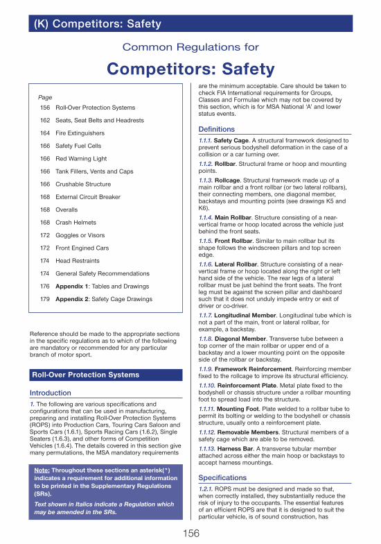
156 (K) Competitors: Safety Reference should be made to the appropriate sections in the specific regulations as to which of the following are mandatory or recommended for any particular branch of motor sport. Roll-Over Protection Systems Introduction 1. The following are various specifications and configurations that can be used in manufacturing, preparing and installing Roll-Over Protection Systems (ROPS) into Production Cars, Touring Cars Saloon and Sports Cars (1.6.1), Sports Racing Cars (1.6.2), Single Seaters (1.6.3), and other forms of Competition Vehicles (1.6.4). The details covered in this section give many permutations, the MSA mandatory requirements are the minimum acceptable. Care should be taken to check FIA International requirements for Groups, Classes and Formulae which may not be covered by this section, which is for MSA National ‘A’ and lower status events. Definitions 1.1.1. Safety Cage. A structural framework designed to prevent serious bodyshell deformation in the case of a collision or a car turning over. 1.1.2. Rollbar. Structural frame or hoop and mounting points. 1.1.3. Rollcage. Structural framework made up of a main rollbar and a front rollbar (or two lateral rollbars), their connecting members, one diagonal member, backstays and mounting points (see drawings K5 and K6). 1.1.4. Main Rollbar. Structure consisting of a near- vertical frame or hoop located across the vehicle just behind the front seats. 1.1.5. Front Rollbar. Similar to main rollbar but its shape follows the windscreen pillars and top screen edge. 1.1.6. Lateral Rollbar. Structure consisting of a near- vertical frame or hoop located along the right or left hand side of the vehicle. The rear legs of a lateral rollbar must be just behind the front seats. The front leg must be against the screen pillar and dashboard such that it does not unduly impede entry or exit of driver or co-driver. 1.1.7. Longitudinal Member. Longitudinal tube which is not a part of the main, front or lateral rollbar, for example, a backstay. 1.1.8. Diagonal Member. Transverse tube between a top corner of the main rollbar or upper end of a backstay and a lower mounting point on the opposite side of the rollbar or backstay. 1.1.9. Framework Reinforcement. Reinforcing member fixed to the rollcage to improve its structural efficiency. 1.1.10. Reinforcement Plate. Metal plate fixed to the bodyshell or chassis structure under a rollbar mounting foot to spread load into the structure. 1.1.11. Mounting Foot. Plate welded to a rollbar tube to permit its bolting or welding to the bodyshell or chassis structure, usually onto a reinforcement plate. 1.1.12. Removable Members. Structural members of a safety cage which are able to be removed. 1.1.13. Harness Bar. A transverse tubular member attached across either the main hoop or backstays to accept harness mountings. Specifications 1.2.1. ROPS must be designed and made so that, when correctly installed, they substantially reduce the risk of injury to the occupants. The essential features of an efficient ROPS are that it is designed to suit the particular vehicle, is of sound construction, has Common Regulations for Competitors: Safety Page 156 Roll-Over Protection Systems 162 Seats, Seat Belts and Headrests 164 Fire Extinguishers 166 Safety Fuel Cells 166 Red Warning Light 166 Tank Fillers, Vents and Caps 166 Crushable Structure 168 External Circuit Breaker 168 Overalls 168 Crash Helmets 172 Goggles or Visors 172 Front Engined Cars 174 Head Restraints 174 General Safety Recommendations 176 Appendix 1: Tables and Drawings 179 Appendix 2: Safety Cage Drawings Note: Throughout these sections an asterisk(*) indicates a requirement for additional information to be printed in the Supplementary Regulations (SRs). Text shown in Italics indicate a Regulation which may be amended in the SRs.
Transcript of Common Regulations for Competitors: Safety Blue Book 2017 - Section... · main rollbar and a front...
156
(K) Competitors: Safety
Reference should be made to the appropriate sectionsin the specific regulations as to which of the followingare mandatory or recommended for any particularbranch of motor sport.
Roll-Over Protection Systems
Introduction1. The following are various specifications andconfigurations that can be used in manufacturing,preparing and installing Roll-Over Protection Systems(ROPS) into Production Cars, Touring Cars Saloon andSports Cars (1.6.1), Sports Racing Cars (1.6.2), SingleSeaters (1.6.3), and other forms of CompetitionVehicles (1.6.4). The details covered in this section givemany permutations, the MSA mandatory requirements
are the minimum acceptable. Care should be taken tocheck FIA International requirements for Groups,Classes and Formulae which may not be covered bythis section, which is for MSA National ‘A’ and lowerstatus events.
Definitions1.1.1. Safety Cage. A structural framework designed toprevent serious bodyshell deformation in the case of acollision or a car turning over.
1.1.2. Rollbar. Structural frame or hoop and mountingpoints.
1.1.3. Rollcage. Structural framework made up of amain rollbar and a front rollbar (or two lateral rollbars),their connecting members, one diagonal member,backstays and mounting points (see drawings K5 andK6).
1.1.4. Main Rollbar. Structure consisting of a near-vertical frame or hoop located across the vehicle justbehind the front seats.
1.1.5. Front Rollbar. Similar to main rollbar but itsshape follows the windscreen pillars and top screenedge.
1.1.6. Lateral Rollbar. Structure consisting of a near-vertical frame or hoop located along the right or lefthand side of the vehicle. The rear legs of a lateralrollbar must be just behind the front seats. The frontleg must be against the screen pillar and dashboardsuch that it does not unduly impede entry or exit ofdriver or co-driver.
1.1.7. Longitudinal Member. Longitudinal tube which isnot a part of the main, front or lateral rollbar, forexample, a backstay.
1.1.8. Diagonal Member. Transverse tube between atop corner of the main rollbar or upper end of abackstay and a lower mounting point on the oppositeside of the rollbar or backstay.
1.1.9. Framework Reinforcement. Reinforcing memberfixed to the rollcage to improve its structural efficiency.
1.1.10. Reinforcement Plate. Metal plate fixed to thebodyshell or chassis structure under a rollbar mountingfoot to spread load into the structure.
1.1.11. Mounting Foot. Plate welded to a rollbar tube topermit its bolting or welding to the bodyshell or chassisstructure, usually onto a reinforcement plate.
1.1.12. Removable Members. Structural members of asafety cage which are able to be removed.
1.1.13. Harness Bar. A transverse tubular memberattached across either the main hoop or backstays toaccept harness mountings.
Specifications1.2.1. ROPS must be designed and made so that,when correctly installed, they substantially reduce therisk of injury to the occupants. The essential featuresof an efficient ROPS are that it is designed to suit theparticular vehicle, is of sound construction, has
Common Regulations for
Competitors: Safety
Page
156 Roll-Over Protection Systems
162 Seats, Seat Belts and Headrests
164 Fire Extinguishers
166 Safety Fuel Cells
166 Red Warning Light
166 Tank Fillers, Vents and Caps
166 Crushable Structure
168 External Circuit Breaker
168 Overalls
168 Crash Helmets
172 Goggles or Visors
172 Front Engined Cars
174 Head Restraints
174 General Safety Recommendations
176 Appendix 1: Tables and Drawings
179 Appendix 2: Safety Cage Drawings
Note: Throughout these sections an asterisk(*)indicates a requirement for additional informationto be printed in the Supplementary Regulations(SRs).
Text shown in Italics indicate a Regulation whichmay be amended in the SRs.
158
adequate mountings and is a close fit to thebodyshell.
1.2.2. The ROPS must not unduly impede Driver andCo-Driver access to the vehicle. Members may intrudeinto the interior space by passing through thedashboard, front side trim, rear side trim, and rear seatswhich may be folded down. ROPS must not extendbeyond the front upper or rear suspension mountingpoints of the vehicle, with the exception of backstayswhich may extend beyond the rear suspensionmounting points if necessary to achieve the required30° angle. Any modification to a homologated ROPS(other than fitment of door bars and harness bars) isprohibited. Tubes must not carry any fluids.
1.2.3. Compulsory Diagonal Member. Different waysof fitting the compulsory diagonal member (seedrawings K5 and K6). The combination of severalmembers is permitted.
1.2.4. Optional Reinforcing Members. Each type ofreinforcement (see drawings K7 to K12) may be usedseparately or combined with others.
1.2.5. Deleted.
Technical Specifications1.3.1. Main, Front and Lateral Rollbars. These framesor hoops must be made in one piece without joints.Their construction must be smooth and even, withoutripples or cracks. The vertical part of the main rollbarmust be as straight as possible and as close aspossible to the interior contour of the bodyshell. Thefront leg of the front rollbar or a lateral rollbar must bestraight, or if it is not possible, must follow thewindscreen pillars and have only one bend unless awindscreen pillar reinforcement [1.3.5(e)] is fitted.
The mounting foot must not be rearward of theforemost point of the rollbar.
Where the main rollbar forms the rear legs of a lateralrollbar (see drawing K6), the connection to the lateralrollbar must be at roof level. To achieve an efficientmounting to the bodyshell, the original interior trim maybe modified around the safety cage and its mountings bycutting it away or by distortion. However, this modificationdoes not permit the removal of the complete parts ofupholstery or trim. Where necessary, the fusebox may berelocated to enable a rollcage to be fitted.
1.3.2. Mounting of ROPS to the Bodyshell.
Minimum mountings are:1 for each leg of the main or lateral rollbar.1 for each leg of the front rollbar.1 for each backstay (see 1.3.3).
Each mounting foot of the front, main and lateralrollbars must include a reinforcement plate of amaterial of at least the same thickness as the wallof the tube to which it is being welded(minimum 3mm).
Each mounting foot must be attached by at least threebolts, minimum M8 150 grade 8.8, on a steelreinforcement plate at least 3mm thick and of at least120cm2 area which is welded to the bodyshell (seedrawings K13 to K18). The mounting feet mayalternatively be welded direct to the reinforcementplate. This does not apply to backstays (see 1.3.3).
1.3.3. Backstays. These are compulsory and must beattached near the roofline and near the top outer bends
of the main rollbar on both sides of the car. They mustmake an angle of at least 30° with the vertical, must runrearwards and be straight and as close as possible tothe interior side panels of the bodyshell. Their materialsspecification, diameter and thickness must be asdefined in 1.4.1. Forward facing stays are permitted ifan angle of 30° cannot be achieved with Backstays,providing they do not unduly impede Driver andCo-Driver access to the vehicle.Their mountings must be reinforced by plates. Eachbackstay should be secured by bolts having acumulative section area at least two thirds of thatrecommended for each rollbar leg mounting in 1.3.2above, and with identical reinforcement plates of a least60cm2 area (see drawing K19).A single bolt in double shear is permitted, providing it isof adequate section and strength (see drawing K20)and provided that a bush is welded into the backstay.The mounting feet may alternatively be welded direct tothe reinforcement plate.1.3.4. Diagonal Members. At least one diagonalmember must be fitted. Their location must be inaccordance with drawings K5 or K6 and they must bestraight. The combination of several diagonal membersis permitted.Where two diagonals in the form of a cross are used, atleast one of the diagonals must be a single piece tube.The attachment points of the diagonal members mustbe so located that they cannot cause injuries. They maybe made removable but must be in place duringevents. The lower end of the diagonal must join themain rollbar or back-stay not further than 100mm fromthe mounting foot. The upper end must join the mainrollbar not further than 100mm from the junction of thebackstay joint, or the backstay not more than 100mmfrom its junction with the main rollbar.They must comply with the minimum specification setout in 1.4.1. A diagonal member fixed to the bodyshellmust have reinforcement plates as defined in 1.3.3.1.3.5. Optional Reinforcement of ROPS. The diameter,thickness and material of reinforcements must be asdefined in 1.4.1. They must be either welded in positionor installed by means of demountable joints.Reinforcement tubes must not be attached to thebodyshell.
(a) Transverse Reinforcing Members:The fitting of two transverse members as shown indrawing K9 is permitted. The transverse memberfixed to the front rollbar must not encroach upon thespace reserved for the driver or co-driver. It must beplaced as high as possible but its lower edge mustnot be higher than the top of the dashboard.
(b) Doorbars (for side protection):Longitudinal members must be fitted at each sideof the vehicle (see drawings K9 and K12). Theymay be removable.The side protection must be as high as possiblebut not higher than one half of the total height ofthe door aperture measured from its base.Where two members in the form of a cross areused, at least one of the members must be asingle piece tube.Where configuration 12(j) is used a reinforcinggusset must connect the tubes along thehorizontal length.
Competitor Safety (K)
160
(K) Competitors: Safety
(c) Roof Reinforcement:Reinforcing the upper part of the rollcage by addingmembers as shown in drawing K10 is permitted.
(d) Reinforcement of bends and junctions:The reinforcement of the junction between themain rollbar or the front rollbar and thelongitudinal members is permitted as shown indrawing K12 as is the reinforcement of the toprear bends of the lateral rollbars.
The ends of these reinforcing tubes must not bemore than half way down or along the members towhich they are attached.
(e) Windscreen Pillar Reinforcement:A tube the upper end of which must be less than100mm from the junction between the front(lateral) rollbar and the longitudinal (transversal)member and the lower end less than 100mm fromthe front mounting foot of the front (lateral) rollbar,as shown in drawing K62.The tube may be bent on condition that it isstraight in side view and that the angle of thebend does not exceed 20°.
1.3.6. Protective Padding. Where the driver’s or co-driver’s bodies or crash helmets could come intocontact with the ROPS, non-flammable padding shouldbe provided for protection (1.6.6).
1.3.7. Removable Members. Should removablemembers be used in the construction of a ROPS, thedemountable joints used must comply with anapproved type (see drawings K21 to K30). The screwsand bolts must be of adequate diameter and of ISOStandard 8.8 or better. FIA homologated demountablejoints are also permitted.
Demountable joints must not be used as part of a main,front or lateral rollbar because they act as hinges in theprincipal structure and allow deformation. Their use issolely for attaching members to the rollbars and forattaching a lateral rollbar to a main rollbar (see drawingK2). In this last case, hinged joints in drawings K21 toK30 must not be used.1.3.8. Guidance on Welding. All welding should be ofthe highest possible quality with full penetration andpreferably using a gas shielded arc. Although goodexternal appearance of a weld does not necessarilyguarantee its quality, poor looking welds are never a signof good workmanship. When using heat-treated steel theinstructions of the manufacturer must be followed(special electrodes, gas protected welding). It is to beemphasised that the use of heat-treated or mediumcarbon steels may cause problems and that badfabrication may result in a decrease in strength (causedby brittle heat-affected zones) or inadequate ductility.1.3.9. Harness Bars. Minimum dimensions 38mm x2.5mm or 40mm x 2.0mm. Cold Drawn SeamlessCarbon Steel with minimum tensile strength of350N/mm2. Harness straps may be attached by loopingaround the tube or by threaded fixings using inserts asdrawing No. 44 welded into the tubes(s).
Material Specifications1.4.1. Specifications of the tubes used:
Minimum MaterialCold Drawn Seamless Unalloyed Carbon Steel,containing a maximum of 0.3% of carbon.
Note: For an unalloyed carbon steel the maximumcontent of additives is 1.7% for manganese and 0.6%for other elements.Minimum Yield Strength350 N/mm2
Minimum Dimensions (Ø in mm)a) Mandatory tubular members
45 x 2.5 (1.75” x 0.095”) or 50 x 2.0 (2.0” x 0.083”).38 x 2.5 (1.5” x 0.095”) or 40 x 2.0 (1.6” x 0.083”).(For roll cages/bars approved prior to 1.1.95).
b)Optional tubular members38 x 2.5 (1.5” x 0.095”) or 40 x 2.0 (1.6” x 0.083”).
1.4.2. In selecting the steel, attention must be paid toobtaining good elongation properties and adequateweldability.1.4.3. The tubing must be bent by a cold workingprocess and the centreline bend radius must be atleast three times the tube diameter. If the tubing isovalised during bending, the ratio of minor to majordiameter must be 0.9 or greater.
ExceptionsThe only exceptions to the foregoing requirements forSaloon, single seater and Sports Cars are as follows:1.5.1. ROPS manufacturers may make application tothe MSA for a Roll Over Protection System (ROPS)Certificate to be issued.Note: ROPS manufacturers wishing to make applicationfor such a certificate should contact the MSA TechnicalDepartment in order to obtain details of therequirements to be met and the fees payable. Subjectto these requirements being met a ROPS Certificatewill be raised and issued. Duly authorised copies of thiscertificate containing a drawing, photographs, a copyof the manufacturers declaration that the ROPS meetsthe required regulations should be available to eventScrutineers.1.5.2. Each ROPS manufactured after 1.1.97 for whichthe MSA or the FIA has issued a ROPS (Rollcage)Certificate must bear an identification plate which detailsthe manufacturer and the manufacturer’s part numberallocated to the cage. Details of this identity plate are tobe included on the ROPS (Rollcage) certificate.
Vehicle Categories Covered1.6.1. Series Production, Touring and Sports Cars.
(a) Production cars, Touring Cars, Sports cars up to2,000cc – Basic rollbar/rollcage complying withK1 or K2.
(b) Production Cars and Touring Cars over 2,000cc –Rollbar/rollcage complying with K3 or K4.
(c) Sports cars over 2,000cc – Rollbar/rollcagecomplying with K3 or K4 or K60(i) & (ii) and K31.
The different possibilities of installing the optionalreinforcing members to the rollcage are shown indrawings K7 to K12.
Each type of reinforcement (drawings to K7 to K12)may be used separately or combined with one orseveral others).
These reinforcements can be installed in each of thebasic rollcages (drawings K1 to K4).
162
(K) Competitors: Safety
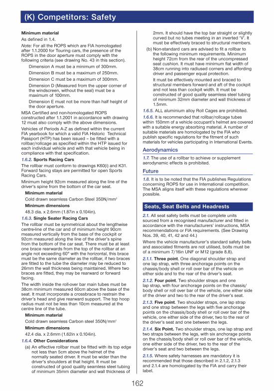
Minimum materialAs defined in 1.4.Note: For all the ROPS which are FIA homologatedafter 1.1.2000 for Touring cars, the presence of theROPS in the door aperture must comply with thefollowing criteria (see drawing No. 43 in this section).
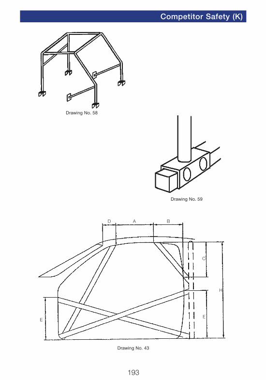
Dimension A must be a minimum of 300mm.Dimension B must be a maximum of 250mm.Dimension C must be a maximum of 300mm.Dimension D (Measured from the upper corner ofthe windscreen, without the seal) must be amaximum of 100mm.Dimension E must not be more than half height ofthe door aperture.
MSA Certified and non-homologated ROPSconstructed after 1.1.2001 in accordance with drawing12 must also comply with the above dimensions.Vehicles of Periods A-Z as defined within the currentFIA yearbook for which a valid FIA Historic TechnicalPassport (HTP) has been issued – be fitted with arollbar/rollcage as specified within the HTP issued foreach individual vehicle and with that vehicle being incompliance with that specification.1.6.2. Sports Racing CarsThe rollbar must conform to drawings K60(i) and K31.Forward facing stays are permitted for open SportsRacing Cars.Minimum height 92cm measured along the line of thedriver’s spine from the bottom of the car seat.
Minimum materialCold drawn seamless Carbon Steel 350N/mm2
Minimum dimensions48.3 dia. x 2.6mm (1.87in x 0.104in).
1.6.3. Single Seater Racing CarsThe rollbar must be symmetrical about the lengthwisecentre-line of the car and of minimum height 90cmmeasured vertically from the base of the cockpit or92cm measured along the line of the driver’s spinefrom the bottom of the car seat. There must be at leastone brace rearwards from the top of the rollbar at anangle not exceeding 60° with the horizontal, this bracemust be the same diameter as the rollbar, if two bracesare fitted to the tube the diameter may be reduced to26mm the wall thickness being maintained. Where twobraces are fitted, they may be rearward or forwardfacing.The width inside the roll-over bar main tubes must be38cm minimum measured 60cm above the base of theseat. It must incorporate a crossbrace to restrain thedriver’s head and give rearward support. The top hoopradius must not be less than 10cm measured at thecentre line of the tube.
Minimum materialCold drawn seamless Carbon steel 350N/mm2
Minimum dimensions42.4 dia. x 2.6mm (1.62in x 0.104in).
1.6.4. Other Considerations(a) An effective rollbar must be fitted with its top edge
not less than 5cm above the helmet of thenormally seated driver. It must be wider than thedriver’s shoulders at that height. It must beconstructed of good quality seamless steel tubingof minimum 35mm diameter and wall thickness of
2mm. It should have the top bar straight or slightlycurved but no tubes meeting in an inverted ‘V’. Itmust be effectively braced to structural members.
(b) Non-standard cars are advised to fit a rollbar tothe following minimum requirements. Minimumheight 72cm from the rear of the uncompressedseat cushion. It must have minimum flat width of38cm running into radiused corners and affordingdriver and passenger equal protection.It must be effectively mounted and braced tostructural members forward and aft of the cockpitand not less than cockpit width. It must beconstructed of good quality seamless steel tubingof minimum 32mm diameter and wall thickness of1.5mm.
1.6.5. ALL aluminium alloy Roll Cages are prohibited.1.6.6. It is recommended that rollbar/rollcage tubeswithin 150mm of a vehicle occupant’s helmet are coveredwith a suitable energy absorbing material. A number ofsuitable materials are homologated by the FIA whopublish specific regulations for the fitment of suchmaterials for vehicles participating in International Events.
Aerodynamics1.7. The use of a rollbar to achieve or supplementaerodynamic effects is prohibited.
Future1.8. It is to be noted that the FIA publishes Regulationsconcerning ROPS for use in International competition.The MSA aligns itself with these regulations whereverpossible.
Seats, Seat Belts and Headrests
2.1. All seat safety belts must be complete unitssourced from a recognised manufacturer and fitted inaccordance with the manufacturers’ instructions, MSArecommendations or FIA requirements. (See DrawingNos. 39, 40, 41, 42 and 44.)Where the vehicle manufacturer’s standard safety beltsand associated fitments are not utilised, bolts must beof a minimum 7/16in UNF or M12 (grade 8.8).
2.1.1. Three point. One diagonal shoulder strap andone lap strap, with three anchorage points on thechassis/body shell or roll over bar of the vehicle oneither side and to the rear of the driver’s seat.
2.1.2. Four point. Two shoulder straps and onelap strap, with four anchorage points on the chassis/body shell or roll over bar of the vehicle, one either sideof the driver and two to the rear of the driver’s seat.
2.1.3. Five point. Two shoulder straps, one lap strapand one strap between the legs with five anchoragepoints on the chassis/body shell or roll over bar of thevehicle, one either side of the driver, two to the rear ofthe driver’s seat and one between the legs.
2.1.4. Six Point. Two shoulder straps, one lap strap andtwo straps between the legs, with six anchorage pointson the chassis/body shell or roll over bar of the vehicle,one either side of the driver, two to the rear of thedriver’s seat and two between the legs.
2.1.5. Where safety harnesses are mandatory it isrecommended that those described in 2.1.2, 2.1.3and 2.1.4 are homologated by the FIA and carry theirlabel.
164
(K) Competitors: Safety
2.1.6. It is permitted to make a hole in series productionseats to allow secure anchoring of seat belts.
2.1.7. All seat belts used on International events mustbe homologated by the FIA, and carry their label.
2.1.8. It is not permitted to mix parts of seat belts. Onlycomplete sets as supplied by manufacturers are to beused.
2.1.9. Only one release mechanism is permitted oneach seat belt configuration and this must be availablefor the wearer to operate whilst seated in thecompeting position.
2.1.10. The anchorage points to the rear should bepositioned so that the strap from the shoulder is asnear horizontal as possible. It should not be located onthe floor directly behind the driver/co-driver.
2.1.11. Seat belts once involved in a serious accidentshould be discarded as they are likely to havestretched. Belts subjected to oil, acid or heat should bereplaced.
2.2. Seats. All seats should be correctly located andsecurely anchored in such a way as to allow nomovement in squab or backrest. When installing aCompetition Seat, carry out the following checks beforeselection or purchase:
(a) Study the requirements of the vehicle concernedand ask the manufacturer’s advice andrecommendations.
(b) Check that the seat is suitable for the type offorces to which it could be subjected. These willinclude fore and aft and lateral loadings.
(c) Check that the seat carries full instructions forinstallation in your vehicle.
(d) Check that suitable mounting installations areavailable from the manufacturer.
(e) Ask the manufacturer to confirm that the seatframe is suitable for your Motor Sport discipline.
(f) If the original seat attachments or supports arechanged, the new parts must either be approvedfor that application by the seat manufacturer ormust comply with the following specifications (seedrawing No. K32).
2.2.1. Supports must be attached to the shell/chassisvia at least 4 mounting points per seat using bolts witha minimum diameter of 8mm and counterplates,according to drawing No. K32. The minimum area ofcontact between support, shell/chassis andcounterplate is 40 sq cm for each mounting point. InSeries Production Cars manufacturers’ standard seatmounting points may be used. If quick release systemsare used, they must be capable of withstanding verticaland horizontal forces of 18000N, applied non-simultaneously. If rails for adjusting the seat are used,they must be those originally supplied with thehomologated car or with the seat.
2.2.2. The seat must be attached to the supports via 4mounting points, 2 at the front and 2 at the rear of theseat, using bolts with a minimum diameter of 8mm andreinforcements integrated into the seat.
Each mounting point must be capable of withstandinga force of 15000N applied in any direction.
2.2.3. The minimum thickness of the supports andcounterplates is 3mm for steel and 5mm for light alloy
materials. The minimum longitudinal dimension of eachsupport is 6cm.
2.3. Headrests. On all vehicles where it is notmandatory (13) it is strongly recommended that a headrestraint in the form of a headrest be fitted, as near tothe driver’s/co-driver’s helmet as possible, to preventwhiplash of the neck and spine in case of impact. It isrecommended that they comply with 13.
Fire Extinguishers
3. A fire extinguisher/extinguishing system must becarried on all vehicles, the minimum requirement beingthat the system be charged with one of the permittedextinguishants and be operable by the driver whilstnormally seated either by manual operation or by amechanically/electrically assisted triggering system.
It is recommended that all extinguishers are serviced inaccordance with the manufacturers guidelines, or every24 months, whichever is sooner.
3.1. Capacities. Extinguishers are classified as Small,Medium or Large, and designated as Hand-Held orPlumbed-In. Dry powder extinguishers are prohibited.
3.1.1. Small, Hand operated.
3.1.2.
(a) Medium, Plumbed-In, for discharge into bothcockpit and engine compartment.
(b) Medium, Hand-Operated, for discharge into bothcockpit and engine compartment.
3.1.3. Large, Plumbed-In, for discharge into bothcockpit and engine compartment.
3.1.4. Large, Plumbed-In, for discharge into Enginecompartment, plus Medium, Hand-Held for Driver orRally Co-driver use.
3.1.5. Hand-operated for cockpit (International).
3.1.6. Permitted Extinguishants AFFF, ZERO 2000.(See Table 3.)
Copies of the list of FIA/MSA approved plumbedsystems are available from the MSA.
3.2. Plumbed-In Systems (If AFFF they must beFIA/MSA homologated).
3.2.1. The Large unit should have two points oftriggering, one for the driver (and Co-driver in Rallies)and one outside the car for activation by Marshals etc.
3.2.2. The triggering point from the exterior must bepositioned close to the Circuit Breaker (or combinedwith it) and must be marked by the letter “E’’ in redinside a white circle of at least 10cm diameter with ared edge.
3.2.3. In installing units, the direction of nozzles shouldbe carefully considered, Induction, Exhaust, Ignitionand Fuel pumping systems being the most likely areasfor fire to occur.
3.2.4. Where possible sources of fire exist outside theengine or cockpit areas (i.e. front mounted fuel tanks)advice can be sought from the MSA concerningplumbed-in system installations.
3.2.5. All bottles should discharge simultaneously andmust be operable in any position of the car even ifinverted.

166
(K) Competitors: Safety
3.2.6. The fitting of a pressure gauge is recommended(mandatory for pressurised AFFF units).
3.2.7. Method of Operation: The preferred method ofoperation is electrical which should have its own sourceof energy for triggering, ideally with provision forchecking the integrity of the systems triggering circuit.
3.2.8. Mechanically operated systems, if used, shouldbe fitted with ‘Total Discharge’ valves (i.e. ones thatcontinue to discharge even if the operating mechanismshould fail after triggering).
Hand-held extinguishers which have been adapted, byaddition of pull-cables, rarely have the capability of beingoperated in varying positions and are not acceptable.
3.2.9. Weight checking: Extinguisher systems shouldbe capable of being dismantled for the purpose ofchecking the weight of the extinguishant and theintegrity of the cylinder, also to enable the operatingsystem to be serviced without discharging the contents.The tare weight of the unit must be marked on thecylinder.
3.2.10. Installation: Particular attention should be paidto the installation and maintenance of any system,especially if it is mechanically operated. Pull cablesshould be fitted in such a way that no kinks or ‘S’bends are formed which could cause malfunction.
3.2.11. A list of plumbed-in extinguisher kits that areapproved by the MSA is available on request.
3.3. During events:
3.3.1. All plumbed-in extinguisher systems must be inan ‘ARMED’ condition (i.e. be capable of beingoperated without the removal of any safety device) at alltimes whilst competing or practising in races or speedevents (including during post-event scrutineering), andat all times that crash helmets are worn on rallies (i.e.on Stages etc.).
3.3.2. Any plumbed-in extinguisher system found to beincapable of being operated will be the subject of areport to the Clerk of the Course/Stewards for possiblepenalty as an offence against Safety Regulations.
3.3.3. Checking for correctly ‘Armed’ extinguishersystems, should only be carried out by MSAScrutineers, and/or Judges of Fact nominated for thatpurpose.
3.4. Hand-held extinguishers
3.4.1. Must not be carried loose but should be retainedin positive quick release brackets, secured to thevehicle by a minimum of two 6mm bolts.
3.4.2. Extinguishers with pressure gauges arerecommended.
3.4.3. The tare weight of the unit must be clearlymarked on the cylinder.
3.5. General
It is recommended that all fire extinguisher bottles besecurely mounted within the main structure of thevehicle. It is prohibited to mount bottles of over themedium capacity outside the main structure.
Safety Fuel Cells
4.1. The FIA approved standard for Safety Fuel Cellsis FIA/Spec./FT.3 and FT.5. Fuel cells complying withthis standard are only manufactured by authorised
companies and bear the name of the company,specification, code and date of manufacture stencilledon each cell. No other cells are approved bythe FIA.
4.2. Under FIA regulations the homologation expiresonce the cell is five years old. The validity of thishomologation may be extended for a further two yearsif the cell is inspected and recertified by the originalmanufacturer.
4.3. It is recommended that any safety cell isperiodically inspected on a regular basis.
Red Warning Light
5.1. A rearward facing red warning light of a minimumof 21 watts, with surface area minimum 20cm2,maximum 40cm2, or of 21 watts with a surface areaminimum of 50cm2 and with lens and reflector to EUStandards, must be located within 10cm of the centreline of the vehicle and be clearly visible from the rear.Vehicles fitted with full width bodywork mayalternatively use two lights equally located about thevehicle centre line. An alternative light unit of equal orenhanced constant luminosity or LED lights that areeither homologated by the FIA or comply with relevantEU Regulations may be used.
5.2. The warning light must be switched on whenvisibility conditions are reduced, or as detailed withinchampionship and/or event regulations, or when soinstructed by the Clerk of the Course.
Tank Fillers, Vents and Caps
6. Tank fillers and caps must not protrude beyond thebodywork or be situated within the driver/passengercompartment. The caps must have an efficient lockingaction to reduce the risk of opening during an accidentand to ensure closing after refuelling (14.1.2). Air ventsmust be at least 25cm to the rear of the cockpit andmust be designed to prevent the escape of fuel shouldthe vehicle be inverted. It is recommended that a nonreturn valve is incorporated in the vent system. Theentire fuel tank area ‘Licked by the open air stream’must incorporate a crushable structure as follows:
Crushable Structure
7.1. The crushable structure should be a sandwichconstruction based on a fire resistant core of minimumcrushing strength 25lb/sq in. It is permitted to passwater pipes through this core.
7.2. The minimum thickness of the sandwichconstruction must be 10mm. The fore and aft fuel tankarea, however, must provide for a crushable structureof at least 100mm thickness at its thickest point, theposition of this widest point to be at the constructor’sdiscretion, over a length of at least 35cm after which itmay be generally reduced to 10mm.
7.3. The sandwich construction must include two sheetsof 1.5mm thick aluminium sheet having a tensile strengthof 14 tons/sq in and minimum elongation of 5%.
7.4. All oil tanks mounted outside the main chassisstructure must be surrounded by crushable structure ofminimum thickness 10mm.

168
(K) Competitors: Safety
External Circuit Breaker
8.1. The circuit breaker, when operated, must isolate allelectrical circuits with the exception of those thatoperate fire extinguishers.
8.2. The triggering system for the circuit breaker onsaloons should be situated at the lower part of thewindscreen mounting, preferably on the driver’s side orbelow the rear window.
8.3. On Open Cars the triggering system should besituated on the lower main hoop of the Roll-over Bar onthe driver’s side or at the lower part of the windscreenmounting (as above).
8.4. Alternatively on cars of Periods A to F the mountingpoint may be mounted approximately vertically belowthe line of the scuttle on the driver’s side.
8.5. The triggering system location must be identifiedby a Red Spark on a White-edged Blue triangle (12cmbase), and the ‘On’ and ‘Off’ positions clearly marked.
Overalls
9.1. Clean Flame-Resistant overalls, must be worn tocover from ankle to wrist to neck.
Acceptable standards:
9.1.1. Racing:
FIA 8856-2000
9.1.2. Special Stage Rallies, Sprints and Hill Climbs:
FIA 8856-2000
FIA 1986 Standard
9.1.3. Karting:
As defined in U.13.3.
9.1.4. All Other Events (including overalls inaccordance with Q.13.1.2):
BS6249 part 1 Index A or B (but not part C).
BSEN533
EN533:1995 Index 3
ISO 14116
FIA 8856-2000
FIA 1986 Standard.
9.1.5. For FIA Standard Overalls the homologation labelwill be stitched into the fabric of the garment or on asewn in label. For International use overalls mustcomply with: FIA 8856-2000
9.1.6. As with any item of safety equipment, evidence ofdamage or excessive wear can render it unsuitable foruse. In the case of overalls this could include overfrequent, or incorrect, washing, broken seams orstitching and worn patches. Two piece overalls shouldbe avoided, but if worn must overlap and provide flameresistant coverage.
9.1.7. Due to the complex nature of national teststandards and variations of detailed testing it is notpossible to quote ‘equivalents’ from foreign nationalstandards unless they are FIA approved as detailedabove.
National test standards are in the process of beingsuperseded by European norms (CE Marks), which willprovide a common standard throughout Europe.
9.1.8. Individual competitors are responsible forensuring their own safety and that appropriate flameresistant overalls are worn when mandatory.
9.1.9. Competitors are also strongly advised to wearFlame Resistant gloves, socks, balaclavas andunderwear.
Plastic shoes (such as trainers) should be avoided.
9.1.10. Specific regulations concerning Flame Resistantgloves, socks, balaclavas and underwear are publishedby the FIA and applicable to International events.
9.2. Exceptionally, drivers of three wheeled cars,competing in accordance with A2.2.1 may wear ACU orFIM approved leather overalls.
9.3. When a name appears on a driver’s helmet oroveralls, this must be the name of the person wearingthem.
Crash Helmets
10.1. Crash helmets bearing an MSA approval stickermust be worn at all times during training, practice andcompetition. The user must ensure that the helmet is toa standard currently specified (10.3.1), that it fitsproperly, is secured properly and that it is in aserviceable condition. It is strongly recommended thata flame resistant balaclava, helmet bib or face maskalso be worn.
10.2. Total protection can never be given by anyheadgear, and the best of crash helmets may notentirely prevent head injury or death in a severeaccident. Helmet users must understand that helmetsare deliberately constructed so that the energy of asevere blow will be absorbed by the helmet and therebypartially destroy it. The damage may not be readilyapparent; it is essential therefore that any helmetreceiving a blow in an accident is either replaced orreturned to the manufacturer for competent inspection –this of necessity must be the responsibility of the helmetuser, who will have been aware of the circumstancesunder which the helmet was struck. It is not possiblenor indeed reasonable to expect the scrutineer, in everycase, to observe significant damage. Where there is anydoubt about the helmet’s fitness for its intendedpurpose then the Chief Scrutineer is empowered toremove the MSA Approval Sticker and impound thehelmet for the duration of the meeting. This should be arare occurrence since competitors must appreciate that,once a helmet has served its purpose, it is not onlysensible but necessary to replace it. It is the competitorhimself who must ensure that the helmet which he usesis fully fit for its purpose; it is clear that this is a smallinsurance to pay for one’s life. The competitor alsomight consider that, should he survive an accident, butreceive head injuries having knowingly used apreviously damaged helmet, he could be placing anenormous burden of care upon his family.
10.2.1. Impounding of helmets
Case 1 Pre-Event. If the helmet does not conform withthe required Standards or is in a poor or dangerouscondition, the Chief Scrutineer will impound the helmetfor the duration of the Meeting, removing the MSAsticker. At the close of the Meeting the helmet will bereturned, as received, with the exception of the MSAsticker, to the competitor concerned.

170
(K) Competitors: Safety
Case 2 Accident during the Event. If the competitor isinjured and the helmet is damaged, the ChiefScrutineer will impound the helmet and remove theMSA sticker then seek the advice of the Steward as tofurther action.
Case 3 Accident during Event and competitorevacuated to hospital with head injuries. The ChiefScrutineer will make sure that the helmet has beenseen by the Chief Medical Officer, he will then impoundthe helmet and remove the MSA Sticker. Unless theChief Medical Officer wishes to retain the helmet itmust be despatched to the Technical Department atthe MSA. Unless specifically called for by thecompetitor it will be disposed of after six weeks.
10.3. The competitor is reminded of the followingessential criteria when buying or using his helmet:
(a) Correct Standard.(b) Correct Fit.(c) Security.(d) Condition.
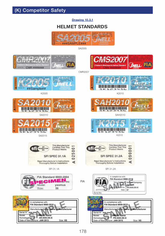
10.3.1. Standards. Helmets bearing one of the undermentioned ‘standards’ may be approved by the MSAsubject to other criteria being met. See alsodrawing 10.3.1.
(a) ALL MSA NATIONAL EVENTSFIA 8860-2004 (Not valid after 31.12.20)FIA 8860-2010FIA 8859-2015SNELL SA2005 (Not valid after 31.12.18)
SNELL SA2010 (Not valid after 31.12.23)SNELL SA2015 (Not valid after 31.12.23)SNELL SAH2010 (Not valid after 31.12.23)SFI Foundation 31.1A, 31.2A (Not valid after31.12.2018)
(b) In addition the following are acceptable for:
MSA National Kart Racing Events (with exception ofKart Drivers under 15 years of age, Cadet andBambino Drivers) and MSA National Junior DragRacing:
SNELL K2005SNELL K2010SNELL K2015SNELL – FIA CMR2007SNELL – FIA CMS2007
(c) For all International Events please refer to the FIARegulations.
Kart Drivers under 15 years of age, Cadet andBambino Drivers. The weight of the helmet may bechecked at any time during an event and must notweigh more than 1,550g:
SNELL – FIA CMR2007
SNELL – FIA CMS2007
Part of the approval procedure is to affix an MSAsticker to the outside of the helmet in the approximatelocation of the driver’s right ear.
Stickers may only be affixed by selected scrutineers, bythe MSA at Motor Sports House, or by selected
Motor Sports HouseOPEN
Monday - Thursday9.30 - 5.30
Friday9.30 - 5.00 (phone enquiries 10.00 - 5.00 please)
Tel: 01753 765000 Fax: 01753 682938
Licence Section:Tel: 01753 765050 Fax: 01753 685426
Website: www.msauk.org

172
(K) Competitors: Safety
manufacturers, after the helmet has been checked forconformity with the standard required and isconsidered to be in a satisfactory condition.
MSA approval stickers, for which a fee of £2.50 ischarged, are printed on foil, and once individuallyaffixed, cannot be reapplied. Note: Stickers suppliedsince 01/01/08 are individually numbered.
Note that helmet standards are regularly reviewed andupdated, and superseded. Standards will periodicallycease to be acceptable; hence an element of ‘lifing’ willalways remain.
Helmets approved for use in all disciplines require ablue MSA sticker to be affixed. Helmets which areaccepted for use in kart racing only require a greenor yellow where applicable MSA sticker to be affixed.These stickers are available from issuing scrutineers.
10.3.2. Fit and Security. To ensure satisfactory fit andsecurity of your helmet, proceed as follows:
(a) Obtain correct size by measuring the crown ofyour head.
(b) Check that there is no side-to-side movement; ahelmet should be as closely fitting as possibleconsistent with comfort.
(c) Tighten straps securely – the chin strap mustbe under tension at all times; ensure thereforethat the strap cannot slip. Chin cups areprohibited.
(d) With head forward attempt to pull up the back ofthe helmet, to ensure the helmet cannot beremoved in this way.
(e) Ensure you can see clearly over each shoulder.(f) Make sure nothing impedes your breathing in the
helmet and never cover your nose or mouth otherthan with a flame resistant balaclava or face mask.Helmets with life-support attachments must onlybe worn if they are connected to a life-supportsystem.
(g) Never wear a scarf, tie or other loose clothingwhich could come loose and possibly cause anaccident.
(h) Ensure that the visor can be opened with onegloved hand.
(i) Satisfy yourself that the back of the helmetprovides protection for your neck.
(j) Do not buy from mail order unless you cansatisfactorily carry out the above checks; return ahelmet unused if it does not fit.
10.3.3. Condition and Care of Helmet
(a) The user himself must bear the primeresponsibility for ensuring that his helmet is fit forthe purpose intended, since significant damage tothe helmet may have been sustained without thisbeing apparent to the scrutineer.
(b) Anything other than minor superficial damage islikely to result in the scrutineer removing the MSAsticker and impounding the helmet for the event.
(c) It is in everyone’s interest for the competitor tobuy the best helmet he can and to look after it(the best is not necessarily the most expensive).A helmet bag should always be used.
(d) There must be no alteration to the structure of a
helmet. Where a radio intercom is fitted this shouldonly be done in accordance with the helmetmanufacturer’s instructions. Fitment of cameras tohelmets by whatever means is not permittedunless an integral camera is provided by thehelmet manufacturer and that model of helmet isapproved under one of the accepted standards.
(e) Use only a weak solution of soft soap and water toclean the interior and exterior of the helmet; donot get the interior too wet.
(f) Some moulded plastic helmets although theymeet approved standards can be seriouslydamaged by substances such as petrol, paint,adhesives, cleaning agents and stickers (not theMSA Stickers) – such damage may not always beapparent; however, crazing or obvious dulling ofthe surface finish could indicate serious structuralweakening of the helmet and is likely to result inthe scrutineer removing the MSA sticker andimpounding the helmet for the event.
(g) The helmet should be stored, preferably in ahelmet bag, in a cool dry place away fromsunlight when not in use. Do not strap the helmetto the roll cage or allow other unrestrainedmovement which could cause the helmet to bedamaged.
(h) A good helmet, properly cared for, is one veryimportant link in a long chain of safety measures.Do not allow it to become the weak link. Do notrely on others. You are responsible for your ownsafety. Do not, through your own fault, become agrave burden to others.
10.4. FHR DeviceIt is permitted to incorporate the use of an FIAapproved FHR Device fitted in accordance with FIAregulations and the below.
For MSA National Events in addition to helmets listedby the FIA as recognised for use with FHR, helmets toSnell SA2015 and Snell SAH2010 are accepted subjectto the anchorage points being marked as homologatedto FIA 8858-2010.
Goggles and Visors
11.1. Either goggles or a visor must be worn at all timesduring training, practice and competing, unless in aclosed vehicle.
11.2. Recommended visor and goggles standard(minimum) BS4110, BS4110:1999, BS EN 1938,European Standard 89/686/EEC.
11.3. Goggles or visors must be clear or neutral densityfilters.
Front Engined Cars
12. With front engine cars a propeller shaft restraintshould be fitted. Either safety hooks or a rigidly fixedsteel panel of not less than 18swg.
174
(K) Competitors: Safety
Head Restraints
13. Head restraints when required to be fitted, must becapable of restraining a 17kg mass decelerating at 5g.
Dimensions to be 10cms x 10cms and located suchthat the driver’s/passenger’s head/helmet is restrainedand cannot move past it under rearward forces, or betrapped between the rollbar and the head restraint. It isrecommended that it be within 5cm of the driver’s/passenger’s helmet when they are normally seated.
General Safety Recommendations
14.1. Owing to the widely varying nature ofcompetitions and the vehicles taking part in them, theMSA takes the view that it would not be in the bestinterests of the competitors to cover all aspects ofsafety precautions with mandatory regulations.Inevitably such regulations could not necessarilyprovide for the most appropriate safety precautions inall foreseeable circumstances.
The MSA therefore draws attention to the followingpoints so that the competitors can consider them andtake precautions as seem appropriate to their ownparticular requirements.
14.1.1. Electrical(a) Batteries – precautions should be taken to
reduce the possibility of acid burns from batteriesin case of accidents. Batteries should be securedwithin a non-conductive leak-proof compartment.
(b) Electrical System – all wiring should be securedand well protected to reduce the risk of fire fromelectrical short circuits.
14.1.2. Fuel(a) Fuel Tanks and Pipes – every effort should be
made to isolate fuel tanks and pipes from thedriver/passenger compartment. The risk of fuelspillage from accident damage can be reduced byuse of bag type tanks or by coating metal tankswith GRP. Tanks should be located so that theyare given maximum protection by the structure ofthe vehicle. Vents should be designed to avoidspillage if the vehicle becomes inverted.
(b) Fuel Fillers – these should be designed andlocated to reduce risk of damage. Filler capsshould not be liable to open in the case of an
accident. Simple screw caps are effective. Thepositive locking of the fuel filler caps isrecommended. The filler pipe to the tank shouldbe of minimum possible length and not protrudebeyond the bodywork (6).
14.1.3. Steering Wheels. The types least likely to inflictinjuries due to breakage should be selected.Uncovered wooden rims should be avoided.
14.1.4. Fire Extinguishers. Even small extinguisherscarried in a vehicle can extinguish or contain firesbefore they develop seriously. Minimumrecommendation is for a 1.75 litre AFFF extinguisher orequivalent with BS4123/EN3 approval (EN3 minimumsize is 2 litre AFFF) and a rating of at least 34B. Moresophisticated equipment is required in many eventsand full vehicle systems are highly recommended(see 3).
14.1.5. Seats. See 2.2.
14.1.6. Headrests. See 2.3.
14.1.7. Radiator Caps. These caps should bepositioned or shielded in such a way that hot water orsteam cannot scald the driver of the vehicle if theybecome opened or broken in an accident.
14.1.8. Clutch and Bell Housing Protection. It isrecommended that a shield be placed to guard theclutch/ bellhousing and to protect in case ofclutch/flywheel derangement. This can be a 1⁄8in steelplate, or sandbag type absorber as used in dragracing.
14.1.9. As a general principal competitors are advisedto replace any safety item, helmet, safety harness, seatsetc., should they have been involved in a severeaccident.
14.2. Paddock Safety. In areas to which the publichas access, no engine shall be run with the gearsengaged whilst the vehicle has any driving wheels notin direct contact with the ground, unless all movingparts are adequately guarded and, with the exceptionof Karts, a competent person is seated in the drivingseat.
14.3. Heat and Flame Resistant Clothing. Whereappropriate and required by specific regulations theFIA standard is shown below, as detailed in FIAYearbook, Appendix L, Chapter III, Article 2. Thesestandards are advised for all competition use whereprotective clothing is either mandatory orrecommended.
Motor Sports HouseOPEN
Monday - Thursday 9.30 - 5.30Friday 9.30 - 5.00 (phone enquiries 10.00 - 5.00 please)
Tel: 01753 765000 Fax: 01753 682938
Licence Section: Tel: 01753 765050 Fax: 01753 685426
Website: www.msauk.org
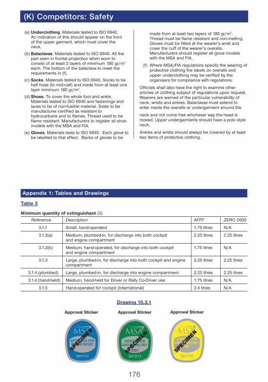
Minimum quantity of extinguishant (3)
Reference Description AFFF ZERO 2000
3.1.1 Small, hand-operated 1.75 litres N/A
3.1.2(a) Medium, plumbed-in, for discharge into both cockpit 2.25 litres 2.25 litresand engine compartment
3.1.2(b) Medium, hand-operated, for discharge into both cockpit 1.75 litres N/Aand engine compartment
3.1.3 Large, plumbed-in, for discharge into both cockpit and engine 2.25 litres 2.25 litrescompartment
3.1.4 (plumbed) Large, plumbed-in, for discharge into engine compartment 2.25 litres 2.25 litres
3.1.4 (hand-held) Medium, hand-held for Driver or Rally Co-Driver use 1.75 litres N/A
3.1.5 Hand-operated for cockpit (International) 2.4 litres N/A
SPEC
IMEN
Approval Sticker Approval Sticker
SPEC
IMEN
SPEC
IMEN
Approval Sticker
Appendix 1: Tables and Drawings
Table 3
Drawing 10.3.1
176
(K) Competitors: Safety
(a) Underclothing. Materials tested to ISO 6940.An indication of this should appear on the frontof the upper garment, which must cover theneck.
(b) Balaclavas. Materials tested to ISO 6940. All thepart seen in frontal projection when worn toconsist of at least 2 layers of minimum 180 gr/m2
each. The bottom of the balaclava to meet therequirements in (f).
(c) Socks. Materials tested to ISO 6940. Socks to behalf hose (to mid-calf) and made from at least onelayer minimum 180 gr/m2.
(d) Shoes. To cover the whole foot and ankle.Materials tested to ISO 6940 and fastenings andlaces to be of non-fusible material. Soles to bemanufacturer certified as resistant tohydrocarbons and to flames. Thread used to beflame resistant. Manufacturers to register all shoemodels with the MSA and FIA.
(e) Gloves. Materials tests to ISO 6940. Each glove tobe labelled to that effect. Backs of gloves to be
made from at least two layers of 180 gr/m2.Thread must be flame resistant and non-melting.Gloves must be fitted at the wearer’s wrist andcover the cuff of the wearer’s overalls.Manufacturers should register all glove modelswith the MSA and FIA.
(f) Where MSA/FIA regulations specify the wearing ofprotective clothing the labels on overalls andupper underclothing may be verified by theorganisers for compliance with regulations.
Officials shall also have the right to examine otherarticles of clothing subject of regulations upon request.Wearers are warned of the particular vulnerability ofneck, wrists and ankles. Balaclavas must extend toenter inside the overalls or undergarment around the
neck and not come free whichever way the head ismoved. Upper undergarments should have a polo styleneck.
Ankles and wrists should always be covered by at leasttwo items of protective clothing.
178
(K) Competitor Safety
HELMET STANDARDS
SPECIMEN FIA
SA2005
K2005
SFI 31.1A SFI 31.2A
Drawing 10.3.1
K2015
CMR2007
SA2010 SAH2010
K2010
SA2015

179
Competitor Safety (K)
Drawing No. 1
Drawing No. 3
Drawing No. 5 Note: Diagonal may be handed to left or right
Drawing No. 6
Drawing No. 4
Drawing No. 2
Appendix 2: Safety Cage Drawings
180
(K) Competitor Safety
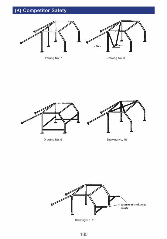
Drawing No. 7
Drawing No. 9
Drawing No. 11
Drawing No. 10
Drawing No. 8

181
Competitor Safety (K)
Drawing No. 12 Optional Reinforcing Members [6]
(a) (b)
(c) (d)
(f)
(g) (h)
(i) (j)
(e)

182
(K) Competitor Safety
Drawing No. 13(b)
Drawing No. 15 Drawing No. 16
Drawing No. 14
Drawing No. 13 Drawing No. 13(a)

183
Competitor Safety (K)
Drawing No. 17
Drawing No. 19
Drawing No. 20
Drawing No. 18

184
(K) Competitor Safety
Drawing No. 21
Drawing No. 23
Drawing No. 24
Drawing No. 22
185
Competitor Safety (K)
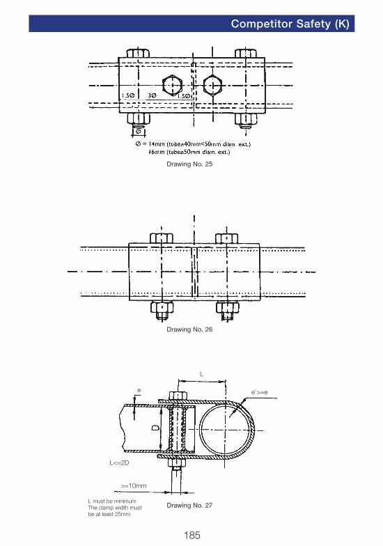
Drawing No. 26
Drawing No. 27
Drawing No. 25
L
e’>=ee
L<=2D
>=10mm
L must be minimumThe clamp width mustbe at least 25mm

186
(K) Competitor Safety
Drawing No. 28
Drawing No. 29
187
Competitor Safety (K)
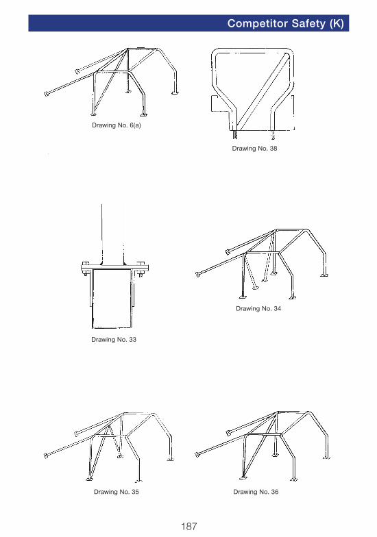
Drawing No. 6(a)
Drawing No. 33
Drawing No. 35 Drawing No. 36
Drawing No. 34
Drawing No. 38
188
(K) Competitor Safety
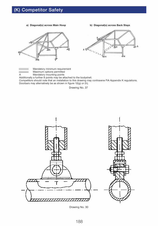
Drawing No. 30
Mandatory minimum requirementMaximum options permitted
A Mandatory mounting pointsAdditionally a further 8 points may be attached to the bodyshell.Competitors should note that an installation to this drawing may contravene FIA Appendix K regulations.Doorbars may alternatively be as shown in figure 12(g) or (h).
Drawing No. 37
a) Diagonal(s) across Main Hoop b) Diagonal(s) across Back Stays
189
Competitor Safety (K)
Maximum25cm
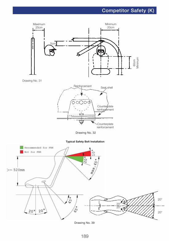
Drawing No. 31
Minimum20cm
60cm
Min
imum
5cm
Drawing No. 32
Reinforcement Seat shell
Counterplatereinforcement
Counterplatereinforcement
Typical Safety Belt Installation
20°
20°20°
20°
Drawing No. 39

190
(K) Competitor Safety
Steel reinforcing plate fixedto the car’s chassis
The bolt should preferablywork in shearing stressand not in traction
Drawing No. 40
Reinforcing platefixed to the
car’s chassis
Plate fixed to the chassis andstrengthened by a reinforced
plate on the other side
Drawing No. 42
Drawing No. 41

191
Competitor Safety (K)
Drawing No. 50
Drawing No. 51
Drawing No. 52
Drawing No. 53
192
(K) Competitor Safety
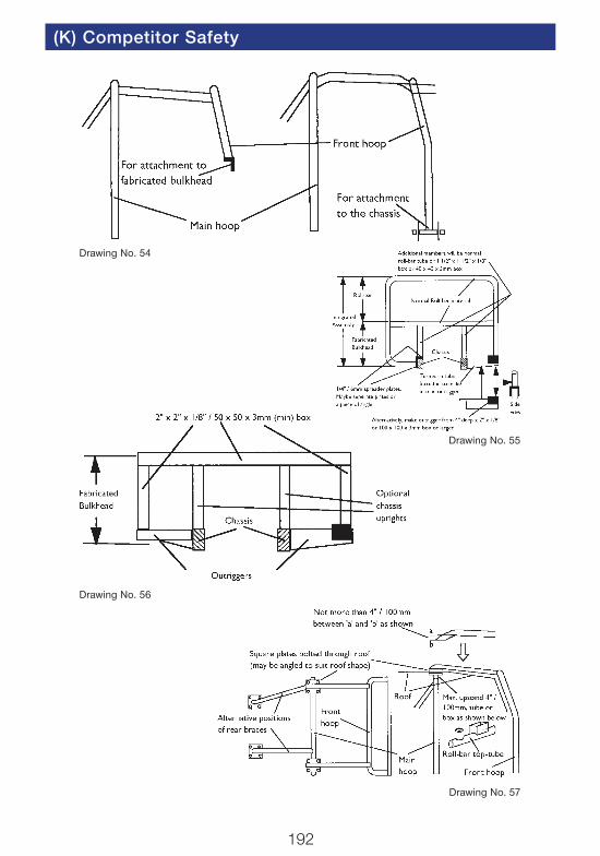
Drawing No. 54
Drawing No. 56
Drawing No. 57
Drawing No. 55
193
Competitor Safety (K)
Drawing No. 43
D
C
EE
H
A B
Drawing No. 58
Drawing No. 59
194
(K) Competitor Safety
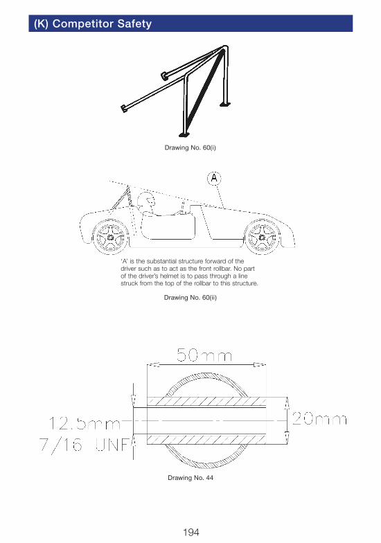
Drawing No. 60(ii)
Drawing No. 60(i)
Drawing No. 44
‘A’ is the substantial structure forward of thedriver such as to act as the front rollbar. No partof the driver’s helmet is to pass through a linestruck from the top of the rollbar to this structure.
195
Competitor Safety (K)
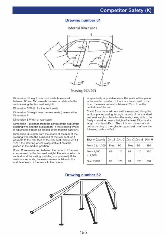
Dimension B Height over front seats (measuredbetween 0° and 15° towards the rear in relation to thevehicle using the test seat weight)
Dimension C Width for the front seats
Dimension D Height over the rear seats (measured asDimension B)
Dimension E Width of rear seats.
Dimension F Distance from the centre of the hub of thesteering wheel to the brake pedal (if the steering wheelis adjustable it must be placed in the median position).
Dimension G Length from the centre of the hub of thesteering wheel to the bulkhead of the rear seat, or ifpossible to the rear face of the rear seat (maximum tilt15°) If the steering wheel is adjustable it must beplaced in the median position.
B and D are measured between the bottom of the seatcompressed by the test seat weight, the axis of which isvertical, and the ceiling (padding compressed). If theseats are separate, the measurement is taken in themiddle of each of the seats. In the case of
longitudinally adjustable seats, the seats will be placedin the median position. If there is a bench seat in thefront, the measurement is taken at 25cm from thecentreline of the car.
C and E are the maximum widths measured along thevertical plane passing through the axis of the standardtest seat weights placed on the seats, being able to befreely maintained over a height of at least 25cm and alength of at least 40cm. The minimum dimensions (incm) according to the cylinder capacity (in cm3) are thefollowing, with H = F+G
Engine Capacity Dim. B Dim. C Dim. D Dim. E Dim. H
From 0 to 1,300 Free 90 Free 90 180
From 1,300 88 110 88 110 200to 2,000
Over 2,000 93 120 93 120 210
Drawing number 61
Drawing number 62