Common Codebook Millimeter Wave Beam Design: Designing ...Common Codebook Millimeter Wave Beam...
14
1 Common Codebook Millimeter Wave Beam Design: Designing Beams for Both Sounding and Communication with Uniform Planar Arrays Jiho Song, Student Member, IEEE, Junil Choi, Member, IEEE, and David J. Love, Fellow, IEEE Abstract—Fifth generation (5G) wireless networks are ex- pected to utilize wide bandwidths available at millimeter wave (mmWave) frequencies for enhancing system throughput. How- ever, the unfavorable channel conditions of mmWave links, e.g., higher path loss and attenuation due to atmospheric gases or water vapor, hinder reliable communications. To compensate for these severe losses, it is essential to have a multitude of antennas to generate sharp and strong beams for directional transmission. In this paper, we consider mmWave systems using uniform planar array (UPA) antennas, which effectively place more antennas on a two-dimensional grid. A hybrid beamforming setup is also considered to generate beams by combining a multitude of antennas using only a few radio frequency chains. We focus on designing a set of transmit beamformers generating beams adapted to the directional characteristics of mmWave links assuming a UPA and hybrid beamforming. We first define ideal beam patterns for UPA structures. Each beamformer is constructed to minimize the mean squared error from the corresponding ideal beam pattern. Simulation results verify that the proposed codebooks enhance beamforming reliability and data rate in mmWave systems. Index Terms—Millimeter wave communications, Hybrid beam- forming, Codebook design algorithm, Uniform planar array. I. I NTRODUCTION W IRELESS broadband systems operating in the millime- ter wave (mmWave) spectrum are thought to be a prime candidate to provide the system throughput enhancements needed for fifth generation (5G) wireless networks [2]–[5]. The wide bandwidths available at mmWave frequencies can be an attractive alternative to the sub-6GHz frequencies employed in most of today’s cellular networks. Also, the directional characteristics of mmWave links are suitable for reducing interuser interference in multiuser channels. However, the higher expected path loss caused by the high carrier frequency, atmospheric gases, and water vapor absorption result in severe link quality degradation. The unfavorable channel conditions at mmWave frequencies necessitate utilizing highly directional transmission with a large beamforming gain. J. Song and D. J. Love are with the School of Electrical and Computer Engineering, Purdue University, West Lafayette, IN 47907 (e-mail: {jihosong, djlove}@purdue.edu). J. Choi is with the Department of Electrical Engineering, POSTECH, Pohang, Gyeongbuk 37673, Korea (e-mail:[email protected]). Parts of this paper were presented at the ICC, London, UK, June 8-12, 2015 [1]. This work was supported in part by the National Science Foundation (NSF) under grant CNS1642982 and the ICT R&D program of MSIP/IITP. [2017(B0717-17-0002), Development of Integer-Forcing MIMO Transceivers for 5G & Beyond Mobile Communication Systems]. The small wavelengths of mmWave frequencies allow a large number of antennas to be implemented in a small form factor on access points and devices. Phased array transmit/receive architectures, such as a uniform linear array (ULA) or uniform planar array (UPA), using high-resolution beamforming are usually considered for mmWave systems [6]. Due to their simplicity, systems using ULAs have been widely studied for use at mmWave frequencies [7]–[15]. UPAs are now being considered due to their higher space efficiency, obtained by packing antennas on a two-dimensional (2D) grid [13]. UPAs can also facilitate three-dimensional (3D) beamforming that takes advantage of both elevation and azimuth domain beamforming to efficiently mitigate interuser interference and eventually increases system capacity [16]. In this paper, we thus consider UPAs to take the advantage of the 2D antenna structures. Millimeter wave systems having a large number of antennas may not be able to use baseband beamforming techniques requiring one radio frequency (RF) chain per antenna due to the high cost and power consumption [4], [5]. Therefore, mmWave systems based on analog beamforming relying upon a single RF chain have been reported in [7]–[12]. Although an analog beamforming architecture can be implemented with inexpensive transmit amplifiers, the envelope constraints placed on the transmitted signals may result in a loss of beamforming gain [?], [8]. To develop mmWave systems operating under modest hardware requirements, we consider hybrid beamforming techniques using a few RF chains wired to sets of phase shifters [12]–[15]. Current cellular systems construct the transmit beamformer based on the channel state information (CSI) at the transmitter, which often is only available through receiver feedback. In feedback-assisted frequency division duplexing architectures, it is essential for the receiver to estimate the CSI using downlink pilot signals [17]–[19]. In large-scale mmWave systems, it may be difficult to explicitly estimate the CSI due to the large number of resources required for training each antenna [18], [19]. Channel estimation algorithms relying on compressed sensing techniques [14], [20]–[22] could be suitable for mmWave downlink training. However, compressed sensing techniques need stringent sparsity requirements to be satisfied. The high dimensionality of a mmWave channel necessitates utilizing a more intuitive channel estimation algorithm. For this reason, mmWave systems may use beam alignment approaches that choose the transmit beamformer without estimating the arXiv:1606.05634v4 [cs.IT] 3 Feb 2017
Transcript of Common Codebook Millimeter Wave Beam Design: Designing ...Common Codebook Millimeter Wave Beam...
1
Common Codebook Millimeter Wave Beam Design:Designing Beams for Both Sounding and
Communication with Uniform Planar ArraysJiho Song, Student Member, IEEE, Junil Choi, Member, IEEE, and David J. Love, Fellow, IEEE
Abstract—Fifth generation (5G) wireless networks are ex-pected to utilize wide bandwidths available at millimeter wave(mmWave) frequencies for enhancing system throughput. How-ever, the unfavorable channel conditions of mmWave links, e.g.,higher path loss and attenuation due to atmospheric gases orwater vapor, hinder reliable communications. To compensatefor these severe losses, it is essential to have a multitude ofantennas to generate sharp and strong beams for directionaltransmission. In this paper, we consider mmWave systems usinguniform planar array (UPA) antennas, which effectively placemore antennas on a two-dimensional grid. A hybrid beamformingsetup is also considered to generate beams by combining amultitude of antennas using only a few radio frequency chains.We focus on designing a set of transmit beamformers generatingbeams adapted to the directional characteristics of mmWavelinks assuming a UPA and hybrid beamforming. We first defineideal beam patterns for UPA structures. Each beamformer isconstructed to minimize the mean squared error from thecorresponding ideal beam pattern. Simulation results verify thatthe proposed codebooks enhance beamforming reliability anddata rate in mmWave systems.
Index Terms—Millimeter wave communications, Hybrid beam-forming, Codebook design algorithm, Uniform planar array.
I. INTRODUCTION
W IRELESS broadband systems operating in the millime-ter wave (mmWave) spectrum are thought to be a prime
candidate to provide the system throughput enhancementsneeded for fifth generation (5G) wireless networks [2]–[5].The wide bandwidths available at mmWave frequencies can bean attractive alternative to the sub-6GHz frequencies employedin most of today’s cellular networks. Also, the directionalcharacteristics of mmWave links are suitable for reducinginteruser interference in multiuser channels. However, thehigher expected path loss caused by the high carrier frequency,atmospheric gases, and water vapor absorption result in severelink quality degradation. The unfavorable channel conditionsat mmWave frequencies necessitate utilizing highly directionaltransmission with a large beamforming gain.
J. Song and D. J. Love are with the School of Electrical and ComputerEngineering, Purdue University, West Lafayette, IN 47907 (e-mail: {jihosong,djlove}@purdue.edu).
J. Choi is with the Department of Electrical Engineering, POSTECH, Pohang,Gyeongbuk 37673, Korea (e-mail:[email protected]).
Parts of this paper were presented at the ICC, London, UK, June 8-12, 2015[1].
This work was supported in part by the National Science Foundation(NSF) under grant CNS1642982 and the ICT R&D program of MSIP/IITP.[2017(B0717-17-0002), Development of Integer-Forcing MIMO Transceiversfor 5G & Beyond Mobile Communication Systems].
The small wavelengths of mmWave frequencies allow a largenumber of antennas to be implemented in a small form factoron access points and devices. Phased array transmit/receivearchitectures, such as a uniform linear array (ULA) or uniformplanar array (UPA), using high-resolution beamforming areusually considered for mmWave systems [6]. Due to theirsimplicity, systems using ULAs have been widely studiedfor use at mmWave frequencies [7]–[15]. UPAs are nowbeing considered due to their higher space efficiency, obtainedby packing antennas on a two-dimensional (2D) grid [13].UPAs can also facilitate three-dimensional (3D) beamformingthat takes advantage of both elevation and azimuth domainbeamforming to efficiently mitigate interuser interference andeventually increases system capacity [16]. In this paper, wethus consider UPAs to take the advantage of the 2D antennastructures.
Millimeter wave systems having a large number of antennasmay not be able to use baseband beamforming techniquesrequiring one radio frequency (RF) chain per antenna dueto the high cost and power consumption [4], [5]. Therefore,mmWave systems based on analog beamforming relying upona single RF chain have been reported in [7]–[12]. Althoughan analog beamforming architecture can be implementedwith inexpensive transmit amplifiers, the envelope constraintsplaced on the transmitted signals may result in a loss ofbeamforming gain [?], [8]. To develop mmWave systemsoperating under modest hardware requirements, we considerhybrid beamforming techniques using a few RF chains wiredto sets of phase shifters [12]–[15].
Current cellular systems construct the transmit beamformerbased on the channel state information (CSI) at the transmitter,which often is only available through receiver feedback. Infeedback-assisted frequency division duplexing architectures,it is essential for the receiver to estimate the CSI usingdownlink pilot signals [17]–[19]. In large-scale mmWavesystems, it may be difficult to explicitly estimate the CSIdue to the large number of resources required for trainingeach antenna [18], [19]. Channel estimation algorithms relyingon compressed sensing techniques [14], [20]–[22] could besuitable for mmWave downlink training. However, compressedsensing techniques need stringent sparsity requirements to besatisfied.
The high dimensionality of a mmWave channel necessitatesutilizing a more intuitive channel estimation algorithm. For thisreason, mmWave systems may use beam alignment approachesthat choose the transmit beamformer without estimating the
arX
iv:1
606.
0563
4v4
[cs
.IT
] 3
Feb
201
7
2
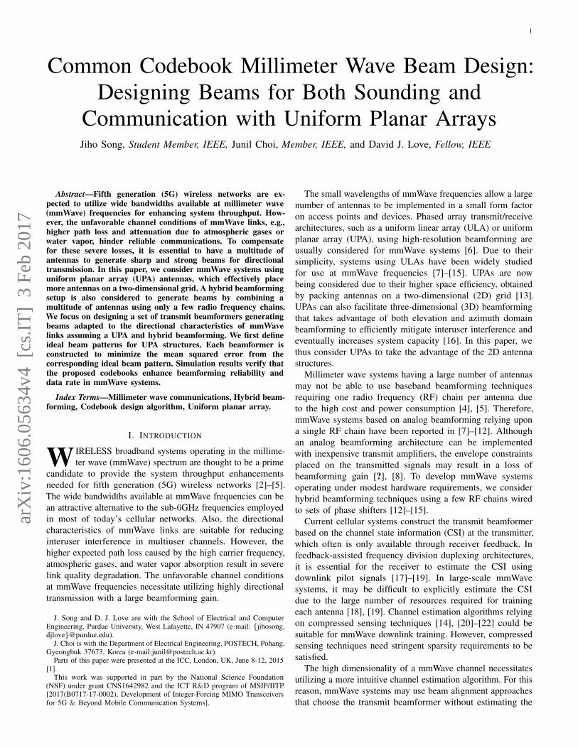
Fig. 1. An overview of a mmWave system with hybrid beamforming.
channel matrix explicitly [7]–[11]. In codebook-based beamalignment approaches, it is desirable to share a single commoncodebook for both channel sounding and data transmission.However, sounding and data transmission enforce conflictingdesign requirements on the beams in the codebook. Forexample, data transmission beams should ideally be narrow toallow for maximum beamforming gain when properly aligned,but channel sounding beams should ideally be wide to sounda wide geographic area with small overhead. In addition,the codebook size must be small to ensure minimal systemoverhead.
The design of a common codebook satisfying the conflictingdesign requirements as well as validating practical mmWavesystems has been studied in [1], [8], [14]. Previous code-book design algorithms are typically optimized for particularvector subspaces characterized by ULA structures. However,codebooks for mmWave systems employing UPAs shouldbe designed to sound a wide geographic area as well asto facilitate a large beamforming gain. In addition, adaptivebeam alignment approaches mostly utilize a multitude ofhierarchical codebooks [8], [10], [13], [14]. This necessitatesdesign guidelines for multi-resolution codebooks that capturethe channel characteristics of UPAs.
In this paper, we propose a practical codebook designalgorithm that utilizes the strong directivity of mmWave links.The codebook design algorithm is developed assuming hybridbeamforming at the transmitter. Based on Parseval’s theorem,we first derive conditions that impose constraint on a beam-former’s beam pattern assuming a UPA structure. To develop acodebook design criterion, we next study ideal beam patterns byutilizing the analytical studies. The codebook is designed suchthat each beamformer minimizes the mean squared error (MSE)between the codebook’s beam pattern and the correspondingideal beam pattern. To access a feasible solution satisfyingthe proposed design guideline, we formulate an optimizationproblem that can produce a set of candidate beamformers. Theorthogonal matching pursuit (OMP) algorithm [23], [24] is thenused to compute each candidate beamformer, satisfying a powerconstrained hybrid beamforming setup. The final beamformeraccomplishing the MSE minimization objective will be chosen
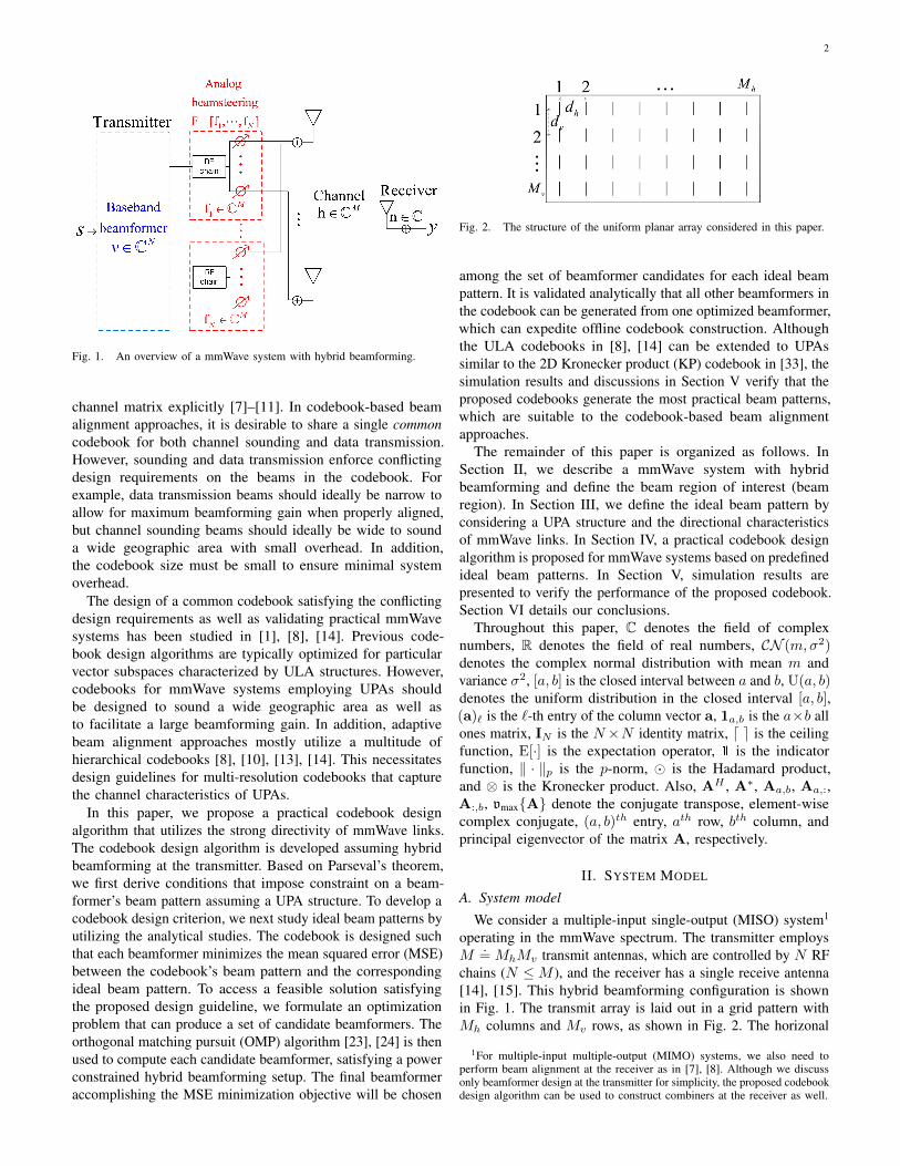
Fig. 2. The structure of the uniform planar array considered in this paper.
among the set of beamformer candidates for each ideal beampattern. It is validated analytically that all other beamformers inthe codebook can be generated from one optimized beamformer,which can expedite offline codebook construction. Althoughthe ULA codebooks in [8], [14] can be extended to UPAssimilar to the 2D Kronecker product (KP) codebook in [33], thesimulation results and discussions in Section V verify that theproposed codebooks generate the most practical beam patterns,which are suitable to the codebook-based beam alignmentapproaches.
The remainder of this paper is organized as follows. InSection II, we describe a mmWave system with hybridbeamforming and define the beam region of interest (beamregion). In Section III, we define the ideal beam pattern byconsidering a UPA structure and the directional characteristicsof mmWave links. In Section IV, a practical codebook designalgorithm is proposed for mmWave systems based on predefinedideal beam patterns. In Section V, simulation results arepresented to verify the performance of the proposed codebook.Section VI details our conclusions.
Throughout this paper, C denotes the field of complexnumbers, R denotes the field of real numbers, CN (m,σ2)denotes the complex normal distribution with mean m andvariance σ2, [a, b] is the closed interval between a and b, U(a, b)denotes the uniform distribution in the closed interval [a, b],(a)` is the `-th entry of the column vector a, 1a,b is the a×b allones matrix, IN is the N×N identity matrix, d e is the ceilingfunction, E[·] is the expectation operator, 1 is the indicatorfunction, ‖ · ‖p is the p-norm, � is the Hadamard product,and ⊗ is the Kronecker product. Also, AH , A∗, Aa,b, Aa,:,A:,b, vmax{A} denote the conjugate transpose, element-wisecomplex conjugate, (a, b)th entry, ath row, bth column, andprincipal eigenvector of the matrix A, respectively.
II. SYSTEM MODEL
A. System model
We consider a multiple-input single-output (MISO) system1
operating in the mmWave spectrum. The transmitter employsM
.= MhMv transmit antennas, which are controlled by N RF
chains (N ≤M ), and the receiver has a single receive antenna[14], [15]. This hybrid beamforming configuration is shownin Fig. 1. The transmit array is laid out in a grid pattern withMh columns and Mv rows, as shown in Fig. 2. The horizonal
1For multiple-input multiple-output (MIMO) systems, we also need toperform beam alignment at the receiver as in [7], [8]. Although we discussonly beamformer design at the transmitter for simplicity, the proposed codebookdesign algorithm can be used to construct combiners at the receiver as well.
3
and vertical elements are spaced uniformly with separationsdh and dv , respectively [6].
Assuming a block fading channel, the input-output expres-sion for data transmission is
y.=√ρhHcs+ n, (1)
where y is the received signal, ρ is the transmit signal-to-noiseratio (SNR), c ∈ CM is the unit norm transmit beamformerh ∈ CM is the block fading mmWave channel, s ∈ C is thetransmit symbol subject to the constraint E[|s|2] ≤ 1, andn ∼ CN (0, 1) is the additive white Gaussian noise (AWGN).
In most beam alignment approaches, the transmit beam-former for data transmission is chosen from a soundingcodebook C =
{c1,1 · · · cQh,Qv
}consisting of Q .
= QhQvbeamformers.2 To sound the mmWave channel, the codewords{c1,1 · · · cQh,Qv} are transmitted one-by-one such as
ysoundingq,p =
√ρhHcq,p + nq,p,
where q ∈ {1, ...Qh}, p ∈ {1, ..., Qv} Note that ysoundingq,p is
the ((q− 1)Qv + p)-th channel observation in the given fadingblock and nq,p ∼ CN (0, 1) is AWGN. The beamformer fordata transmission is then given by c = cq,p with
(q, p) = arg max(q,p)∈Q
∣∣ysoundingq,p
∣∣2, (2)
where Q .= {1, · · · , Qh} × {1, · · · , Qv}.
When implemented, the unit norm transmit beamformerc.= Fv ∈ CM is formed using a combination of an analog
beamsteering matrix F =[f1, · · · , fN
]∈ CM×N consisting of
N unit norm beamsteering vectors and a baseband beamformerv ∈ CN . An analog beamsteering vector fn is realized by aset of RF phase shifters, which is modeled by requiring thatthe vector lie in the equal gain subset
E2B ={f ∈ CM : fm = ejϕm/
√M, ϕm ∈ Z2B
}, (3)
where m ∈ {1, · · · ,M}, ϕm is the phase of the each entry ofthe equal gain vector f = [f1, · · · , fM ]T . To impose practicallimitations on the analog beamforming hardware, we assumethat a digitally-controlled RF phase shifter generates quantizedphases [8]. Each element phase ϕm in (3) is then chosen fromthe set of 2B quantized phases
Z2B.={
0, 2π/2B , · · · , 2π(2B − 1)/2B}. (4)
The weight vector v combining the columns of F performsbeamforming at baseband without equal gain constraints, whilethe combination of F and v is subject to the constraint‖Fv‖22 = 1.
B. Vector subspace for mmWave channels
For the UPA scenario, the mmWave channel is modeledby the combination of a line-of-sight (LOS) path and a few
2Because it is possible to easily deploy a large number of transmit antennas,we assume that Q < M in order to ensure minimal system overhead for beamalignment.
non-line-of-sight (NLOS) paths as [25]–[27]
h =
√MK
1 +Kα0dM (ψh0, ψv0)
+
√M
R(1 +K)
R∑r=1
αrdM (ψhr, ψvr), (5)
where K is the Ricean K-factor, αr ∼ CN (0, 1) is the complexchannel gain, R is the number of NLOS paths, and
dM (ψhr, ψvr).= dMh
(ψhr)⊗ dMv(ψvr) ∈ CM (6)
is the r-th normalized beam defined by the KP of array responsevectors3
dMa(ψar).=
1√Ma
[1, ejψar · · · ej(Ma−1)ψar
]T ∈ CMa (7)
with ψhr = 2πdhλ sin θhr cos θvr and ψvr = 2πdv
λ sin θvr,where θar is the angle of departure (AoD) [6]. Note thata ∈ {h, v} denotes both horizontal and vertical domains.
Millimeter wave channels are expected to have a large RiceanK-factor that is matched with a strong channel directivity [4],[29], [30]. Therefore, we consider a vector subspace definedby a single dominant beam,4 i.e., an array manifold
A .={a : a =
√MdM (ψh, ψv), (ψh, ψv) ∈ B
}, (8)
where B denotes the set of beam directions5 in both horizontaland vertical domains. Then, we need to define proper B todesign good codebooks.
Since the array response vector is periodic such as
dMa(ψa + 2π) = dMa(ψa),
the entire beam region is bounded as Be.= [−π, π)× [−π, π).
We next define the set of possible beam directions thatactually characterizes the array manifold in (8). We consideran AoD distributed as (θh, θv) ∈ [−π2 ,
π2 )× [−π4 ,
π4 ) assuming
sectorized cellular systems. The beam region is then definedas
Bs.=[− 2πdh/λ, 2πdh/λ
)×[−√
2πdv/λ,√
2πdv/λ).
As defined in (7), the beam direction in ψh domain is a functionof not only θh but also θv. Considering the paired ranges inthe horizontal and vertical domains together, the possible rangeof beam directions are bounded for a given AoD θv as
|ψh|θv | ≤ 2πdh cos θv/λ, ψv|θv = 2πdv sin θv/λ.
Under the assumption of dh = dv = d, the bounds in bothdomains give
ψ2h|θv + ψ2
v|θv ≤ (2πd/λ)2. (9)
3For simplicity, we do not consider the electromagnetic interaction betweendeployed antennas [28]. If we define the effective array response vector takingthe electromagnetic mutual couplings into account, the proposed approachcan be directly applied to generate practical beam patterns that consider themutual coupling between deployed antennas.
4Although we mainly focus on designing a codebook for a single dominantbeam, we also consider channels consisting of multiple NLOS paths fornumerical simulations.
5We call the 2D geometric model of the vector subspace as a beam region.
4
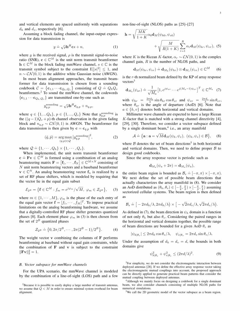
Fig. 3. Two-dimensional beam region under UPA scenario.
The beam region is thus defined by considering a feasible setof beam directions,6 which satisfy the condition in (9), overall possible AoDs θv
Bc.={
(ψh, ψv) ∈ Bs : ψ2h + ψ2
v ≤ (2πd/λ)2}.
We now take a closer look at the beam region Bc. In Fig. 3,the patterned areas Bs\Bc excluded from Bc (which describesthe pairing effect between the horizontal and vertical domains)are negligible compared to the main area. For simplicity, wedevelop a codebook design algorithm without taking intoaccount the pairing between horizontal and vertical domains.For the assumption of d = λ/2, the beam directions aresimplified as ψa = π sin θa, and the beam region is boundedas
Bs.=[− ψB
h , ψBh
)×[− ψB
v , ψBv
)(10)
with ψBh = π, and ψB
v = π/√
2. Finally, we define the arraymanifold by setting B = Bs in (8).
III. FRAMEWORK FOR CODEBOOK DESIGN ALGORITHM
To use a common codebook for both channel sounding anddata transmission, beamformers should be designed to generatebeam patterns satisfying the following criteria:1) Each beamformer should cover a wide geographic area toreduce sounding overhead.2) Each beamformer should have high and uniform gain over adesired beam region to maximize SNR and quality of service.
To provide design guidelines for practical beamformers thatsatisfy the above criteria, it is necessary to design beam patternshaving uniform beamforming gains inside the beam region (tomeet the quality of service requirement) as well as havingno beamforming gain outside the beam region (to maximizeSNR, minimize beam misalignment, and reduce interference).We will refer to these beam patterns as ideal beam patternsthroughout the paper.7
6In case of dh 6= dv , the beam region is defined by an ellipse such as
Bc.={
(ψh, ψv) ∈ Bs :ψ2h
(2πdh/λ)2 +
ψ2v
(2πdv/λ)2≤ 1}
.7The term ideal does not mean the considered beam patters are globally
optimal beam patterns.
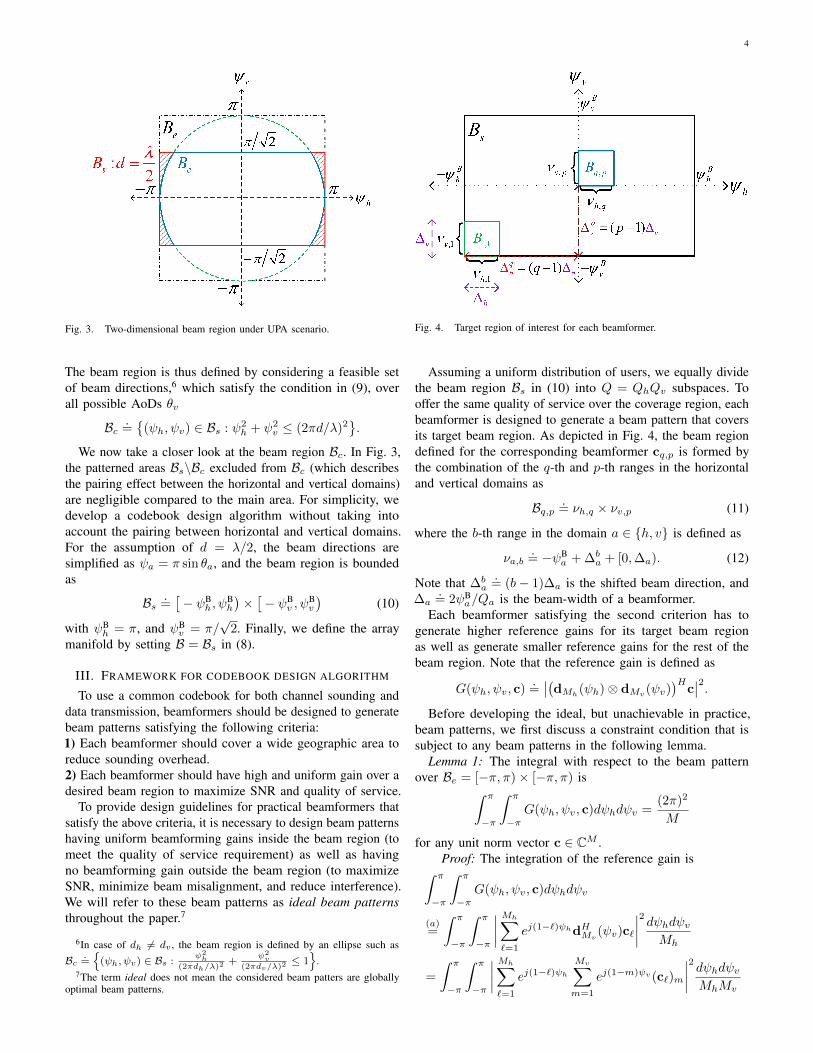
Fig. 4. Target region of interest for each beamformer.
Assuming a uniform distribution of users, we equally dividethe beam region Bs in (10) into Q = QhQv subspaces. Tooffer the same quality of service over the coverage region, eachbeamformer is designed to generate a beam pattern that coversits target beam region. As depicted in Fig. 4, the beam regiondefined for the corresponding beamformer cq,p is formed bythe combination of the q-th and p-th ranges in the horizontaland vertical domains as
Bq,p.= νh,q × νv,p (11)
where the b-th range in the domain a ∈ {h, v} is defined as
νa,b.= −ψB
a + ∆ba + [0,∆a). (12)
Note that ∆ba.= (b− 1)∆a is the shifted beam direction, and
∆a.= 2ψB
a/Qa is the beam-width of a beamformer.Each beamformer satisfying the second criterion has to
generate higher reference gains for its target beam regionas well as generate smaller reference gains for the rest of thebeam region. Note that the reference gain is defined as
G(ψh, ψv, c).=∣∣(dMh
(ψh)⊗ dMv (ψv))H
c∣∣2.
Before developing the ideal, but unachievable in practice,beam patterns, we first discuss a constraint condition that issubject to any beam patterns in the following lemma.
Lemma 1: The integral with respect to the beam patternover Be = [−π, π)× [−π, π) is∫ π
−π
∫ π
−πG(ψh, ψv, c)dψhdψv =
(2π)2
M
for any unit norm vector c ∈ CM .Proof: The integration of the reference gain is∫ π
−π
∫ π
−πG(ψh, ψv, c)dψhdψv
(a)=
∫ π
−π
∫ π
−π
∣∣∣∣ Mh∑`=1
ej(1−`)ψhdHMv(ψv)c`
∣∣∣∣2 dψhdψvMh
=
∫ π
−π
∫ π
−π
∣∣∣∣ Mh∑`=1
ej(1−`)ψhMv∑m=1
ej(1−m)ψv (c`)m
∣∣∣∣2 dψhdψvMhMv

5
(b)=
2π
M
Mh∑`=1
∫ π
−π
∣∣∣∣ Mv∑m=1
ej(1−m)ψv (c`)m
∣∣∣∣2dψv(c)=
(2π)2
M
Mh∑`=1
Mv∑m=1
|(c`)m|2
=(2π)2
M,
where (a) is derived because c.= [cT1 , · · · , cTMh
]T , c` ∈ CMv
and (b), (c) are derived based on the Parseval’s theorem [8]
1
2π
∫ π
−π
∣∣∣∣ M∑m=1
ej(m−1)ψ(a)m
∣∣∣∣2dψ = ‖a‖22
for any vector a ∈ CM .We now define ideal beam patterns by taking Lemma 1 into
account. We assume the (q, p)-th ideal beamformer generatesan ideal beam pattern that is biased toward its desired beamregion. For example, the (q, p)-th beamformer generates anideal beam pattern having a non-zero reference gain for thebeam region Bq,p and zero gain for the rest of the beam regionBs \ Bq,p. The ideal beam pattern is then given by
Gidealq,p (ψh, ψv) = t(ψh, ψv)1Bq,p(ψh, ψv)
subject to the constraint condition derived in Lemma 1 making∫ ∫Bq,p
t(ψh, ψv)dψhdψv =(2π)2
M. (13)
We discuss a distribution of the non-zero reference gaint(ψh, ψv). Assuming a single dominant beam
√MdM (ψh, ψv)
is in Bq,p, the (q, p)-th ideal beamformer is an optimal transmitbeamformer. Under the assumption of a LOS dominant channelmodel, we define the expected data rate conditioned on ‖h‖22as
R.= E
[log2
(1 + ρ|hHcq,p|2
) ∣∣ ‖h‖22]= E
[log2
(1 + ρ‖h‖22|dHM (ψh, ψv)cq,p|2
) ∣∣ ‖h‖22].In the following lemma, we define the non-zero reference gainsthat achieve an upper bound of the expected data rate.
Lemma 2: An ideal beam pattern having identical non-zeroreference gain
Gidealq,p (ψh, ψv) =
QΛ
M1Bq,p(ψh, ψv),
where Λ.= ΛhΛv and Λa
.= π/ψBa for a ∈ {h, v}, satisfies
the upper bound of the expected data rate
Rup = log2
(1 +
ρ‖h‖22QΛ
M
).
Proof: Assuming uniform distribution of dominant beamdirections, the data rate is averaged with respect to theuniformly distributed beam directions (ψh, ψv) ∈ Bq,p. For
Fig. 5. Ideal beam pattern for each beamformer.
a conditioned on ‖h‖22, the expected data rate is bounded as
R = E[
log2
(1 + ρ‖h‖22t(ψh, ψv)
) ∣∣ ‖h‖22]=
∫ ∫Bq,p log2
(1 + ρ‖h‖22t(ψh, ψv)
)dψhdψv∫ ∫
Bq,p dψhdψv
(a)
≤ log2
(1 +
ρ‖h‖22∫ ∫Bq,p t(ψh, ψv)dψhdψv∫ ∫Bq,p dψhdψv
)(b)= log2
(1 +
ρ‖h‖22(2π)2
M∆h∆v
)where ∆a
.= 2ψB
a/Qa is defined in (12). Note that (a) isderived based on Jensen’s inequality and (b) is derived basedon the constraint in (13). The equality in (a) holds if thet(ψh, ψv) is uniform over Bq,p according to
t(ψh, ψv) =(2π)2
M∆h∆v=QΛ
M.
The reference gain is finalized as8 t(ψh, ψv).= min
{1, QΛ
M
}.
In this paper, we have t(ψh, ψv) ≤ 1 because of the assumptionM ≥ QΛ. Finally, the ideal beam pattern becomes
Gidealq,p (ψh, ψv) =
QΛ
M1Bq,p(ψh, ψv)
with (ψh, ψv) ∈ Bs and the corresponding upper bound of theexpected data rate is given by
Rup = log2
(1 +
ρ‖h‖22QΛ
M
). (14)
Example ideal beam patterns are depicted in Fig. 5. Notethat the ideal beam patterns will guide the development of theproposed codebook design algorithm.
IV. PROPOSED CODEBOOK DESIGN ALGORITHM
A. Problem formulation for beam pattern design
In this section, we propose a codebook design algorithmutilizing the predefined ideal beam patterns. The ideal beampatterns are usually unachievable in practice, and we designhybrid beamformers that generate beam patterns close to
8Any reference gain is upper bounded as G(ψh, ψv , c) ≤∥∥dMh (ψh)⊗
dMv (ψv)∥∥22
∥∥c∥∥22
= 1.
6
the ideal beam patterns. Beamformers satisfying the hybridbeamforming setup are formed by combination of an analogbeamsteering matrix and a baseband beamformer such as
cq,p = Fq,pvq,p.
We thus focus on constructing a set of an analog beamsteeringmatrix and a baseband beamformer that minimizes the MSEbetween the ideal beam pattern and the actual beam patten as
(Foptq,p,v
optq,p) (15)
= arg minF,v
∫ ∫Bs
∣∣Gidealq,p (ψh, ψv)−G(ψh, ψv,Fv)
∣∣2dψhdψv,where the combination of F = [f1, · · · , fN ] and v are subjectto ‖Fv‖22 = 1.
Although we have Q beamformers to optimize, the followinglemma shows that it is possible to generate other beamformersfrom one optimized beamformer. The lemma exploits the phaseshifting function defined as
T(F, υ, κ
) .= F�
(dM (υ, κ)11,N
)(16)
=[(
f1 � dM (υ, κ)), · · · ,
(fN � dM (υ, κ)
)]where the normalized array response vector is given by
dM (υ, κ).=
dM (υ, κ)
‖dM (υ, κ)� dM (υ, κ)‖2.
Lemma 3: The beamsteering matrix for the MSE problemin (15) is obtained by shifting phase directions of equal gainvectors in the (1, 1)-th beamsteering matrix such as
Foptq,p = T
(Fopt
1,1,∆qh,∆
pv
).
The baseband beamformers are all
voptq,p = vopt
1,1.
Please see Appendix A for the proof.For the rest of this section, we focus on optimizing the (1, 1)-
th beamformer based on Lemma 3. It is not practical to considercontinuous beam directions for the problem. Therefore, theb-th range νa,b in (12) is quantized with La beam directions9
according to
ψba[`].= −ψB
a + ∆ba + ∆a
`− 0.5
La, (17)
where ` ∈ {1, · · · , La}, b ∈ {1, · · · , Qa}, and a ∈ {h, v}.Both actual and ideal beam patterns are then represented invector forms. The quantized beam pattern is
G(Fv).=[G(ψ1
h[1], ψ1v [1],Fv) · · ·G(ψQhh [Lh], ψQvv [Lv],Fv)
]T,
and the quantized ideal beam pattern is then
Gideal1,1
.=QhΛhMh
(eh ⊗ 1Lh,1
)⊗ QvΛv
Mv
(ev ⊗ 1Lv,1
)(18)
where ea is the first column vector of IQa . The optimizationproblem is then given by
(F1,1,v1,1) = arg minF,v
∥∥Gideal1,1 −G(Fv)
∥∥2
2. (19)
9In the beam region Bs, we consider L .= LhLv beam directions satisfying
LQ ≥M .
To get insights on the structure of the beam patterns in theoptimization (19), we decompose each entry into an arbitrarycomplex number and its complex conjugate. The ideal beampattern vector is decomposed as
Gideal1,1
(a)=QhΛhMh
(eh ⊗ (gh � g∗h)
)⊗ QvΛv
Mv
(ev ⊗ (gv � g∗v)
)=(√
QΛ/M(eh ⊗ gh)⊗ (ev ⊗ gv))
�(√
QΛ/M(eh ⊗ gh)⊗ (ev ⊗ gv))∗. (20)
Note that (a) is derived because the all ones vector in (18) canbe decomposed into any equal gain vector and its element-wisecomplex conjugate as 1La,1 = ga � g∗a, where ga has unitgain entries. Similarly, the actual beam pattern is decomposedas
G(Fv) =((
DHh ⊗DH
v
)Fv)�((
DHh ⊗DH
v
)Fv)∗
(21)
with the set of array vectors for quantized directions in (17)
Da =[Da,1, · · · ,Da,Qa
]∈ CMa×LaQa ,
Da,b = [dMa(ψba[1]), · · · ,dMa
(ψba[La])] ∈ CMa×La .
Unfortunately, there exists no closed-form solution for theminimization problem in (19) because the entries in G(Fv) andGideal
1,1 are found in the form of absolute square of a complexnumber. To access a feasible, but usually suboptimal, solution,we reformulate our problem that compares the decomposedvectors in (20) and (21) for a given (gh,gv)(F|gh,gv ,v|gh,gv
)=
arg minF,v
∥∥∥∥β(DHh ⊗DH
v
)Fv −
√QΛ
M(eh ⊗ gh)⊗ (ev ⊗ gv)
∥∥∥∥2
2
where β ∈ C is a normalization constant. We computethe normalization constant β by differentiating the objectivefunction over β∗ as
∂
∂β∗
∥∥∥∥β(DHh ⊗DH
v
)Fv −
√QΛ
M(eh ⊗ gh)⊗ (ev ⊗ gv)
∥∥∥∥2
2
= β∥∥(DH
h ⊗DHv )Fv
∥∥2
2
−√QΛ
M(Fv)H
(Dh(eh ⊗ gh)⊗Dv(ev ⊗ gv)
)based on Wirtinger derivatives, which simplify differentiationin complex variables [31]. The complex gain that minimizesthe objective function is then given by
β =
√QΛM (Fv)H
(Dh(eh ⊗ gh)⊗Dv(ev ⊗ gv)
)∥∥(DHh ⊗DH
v
)Fv∥∥2
2
(a)=
√QΛM (Fv)H
(Dh,1gh ⊗Dv,1gv
)∥∥(DHh ⊗DH
v
)Fv∥∥2
2
,
where (a) is derived because Da(ea ⊗ ga) = Da,1ga. Byplugging β into the object function, the problem formulation
7
is simplified to
(F|gh,gv ,v|gh,gv
)= arg max
F,v
∣∣(Dh,1gh ⊗Dv,1gv)H
Fv∣∣2∥∥(DH
h ⊗DHv
)Fv∥∥2
2
(a)= arg max
F,v
∣∣(Dh,1gh ⊗Dv,1gv)H
Fv∣∣2,(22)
where (a) is derived because DaDHa = LaQa
MaIMa
and thedenominator is fixed to
∥∥(DHh ⊗DH
v
)Fv∥∥2
2= LQ
M for anyFv satisfying the power constraint ‖Fv‖22 = 1.
We denote the solution for the problem in (22)
c|gh,gv = F|gh,gvv|gh,gv
as a beamformer candidate for a given (gh,gv). We assumethat equal gain vectors in the domain a ∈ {h, v} are subjectto the constrained set10
GILa ={g ∈ CLa : (g)` = ejz, z ∈ ZI
}(23)
with (g)1 = 1. In the proposed algorithm, we generatebeamformer candidates over (gh,gv) ∈ GILh × G
ILv
. Eachbeamformer candidate is a feasible solution accomplishingthe minimization objective in (15). Note that ILh+Lv−2
beamformer candidates are computed because each pair ofequal gain vectors, which is the combination of ILh−1 andILv−1 vectors in both domains, produces a beamformer.
B. OMP algorithm constructing beamformer candidates
We now solve the maximization problem in (22) to generateeach beamformer candidate for a given (gh,gv). An optimalsolution to the problem in (22) is computed as
c|gh,gv.=
Dh,1gh ⊗Dv,1gv∥∥Dh,1gh ⊗Dv,1gv∥∥
2
.
However, F and v may not be able to construct the optimalbeamformer because column vectors in F are subject to theequal gain subset BM in (3).
We first compute a beamsteering vector fn at the n-th update.To remove the (n− 1)-th residual vector11
rn−1 = c|gh,gv − Fn−1vn−1
that is not suppressed in the previous update, the beamsteeringvector is computed as [?], fn = 1√
Mexp (jθn), where
θn ∈ arg maxϑ∈[0,2π)M
∣∣rHn−1ejϑ∣∣2.
The optimal phase vector θn does not have a single uniquesolution because∣∣rHn−1 exp (jθn)
∣∣2 =∣∣rHn−1 exp (jθn) exp(jξ)
∣∣2for any phase angle ξ ∈ [0, 2π). Although the optimal phasevector is given by θn = ∠rn−1 + ξ in [?], we define θn
.=
∠rn−1 with ξ = 0 for simplicity. Note that ∠rn−1 ∈ [0, 2π)M
10Any set of equal gain vectors (gh,gv) ∈ GILh × GILv
construct Gideal1,1 .
The entries in ga have the fixed absolute value, while the phase can be arbitraryin ZI , defined in (4).
11The initial residual vector is defined as r0.= c|gh,gv .
Algorithm 1 Beamformer design based on the OMPInitialization For a given (gh,gv) ∈ GILh × G
ILv
1: Optimal beamformer c|gh,gv.=
Dh,1gh⊗Dv,1gv‖Dh,1gh⊗Dv,1gv‖2
2: Define an initial residual vector r0.= c|gh,gv
3: Define an initial empty matrix F0
Iterative update4: for 1 ≤ n ≤ N5: Choose equal gain vector fn = 1√
Mexp (j∠rn−1)
6: Quantize each phase element ∠(fn)m ∈ Z2B
7: Update beamsteering matrix Fn = [Fn−1, fn] ∈ CM×n8: Update baseband beamformer
vn =vmax{(FHn Fn)−1FHn (Γh⊗Γv)Fn}∥∥Fnvmax{(FHn Fn)−1FHn (Γh⊗Γv)Fn}
∥∥2
∈ Cn,
where Γa.= Da,1gag
Ha DH
a,1 ∈ CMa×Ma
9: Update residual vector rn = c|gh,gv − Fnvn10: end forFinal update11: Update analog beamsteering matrix F|gh,gv = FN12: Update baseband beamformer v|gh,gv = vNFinal output13: Compute codeword candidate c|gh,gv = F|gh,gvv|gh,gv
is the function that returns each element phase of rn−1 ∈ CMin a vector form. Assuming the digitally-controlled RF phaseshifter [8], each element phase in fn is quantized with the setof quantized phases Z2B in (4). The beamsteering matrix atthe n-th update is then given by Fn = [Fn−1, fn] ∈ CM×n.
Similar to the beamformer designs in [14], [15], the problemin (22) can be solved by utilizing the OMP algorithm in [23],[24]. Based on the OMP algorithm, we choose each equalgain vector one-by-one and update the baseband beamformeriteratively in such a way that a combination of F|gh,gv andv|gh,gv minimizes the norm of residual vector
r.= c|gh,gv − F|gh,gvv|gh,gv .
A baseband beamformer vn is then computed by solvingthe maximization problem (22) over v ∈ Cn. To computethe beamformer that satisfies the power constraint of hybridbeamforming system ‖Fv‖22 = 1, the maximization problem isrewritten by changing dummy variables as v = u
‖Fnu‖2 for u ∈Cn. For a given (gh,gv) and Fn, the baseband beamformer atthe n-th update is computed based on the generalized Rayleighquotient solution in [32], such as vn = un
‖Fnun‖2 , where
un = arg maxu∈Cn
uH(FHn(Γh ⊗ Γv
)Fn)u
uH(FHn Fn)u
= vmax{
(FHn Fn)−1FHn(Γh ⊗ Γv
)Fn}
(24)
with Γa.= Da,1gag
Ha DH
a,1 ∈ CMa×Ma .The beamformer at the n-th update becomes cn = Fnvn
and the residual vector rn = c|gh,gv −Fnvn is updated for thefollowing update steps. The iterative process is summarizedin Algorithm 1. Each beamformer candidate is formed bycombination of the updated solution, i.e., F|gh,gv and v|gh,gv ,
c|gh,gv = F|gh,gvv|gh,gv
for a given (gh,gv) ∈ GILh × GILv
.
8
(a) Proposed codebook (b) Codebook in [8] (c) Codebook with gh & gv [14]
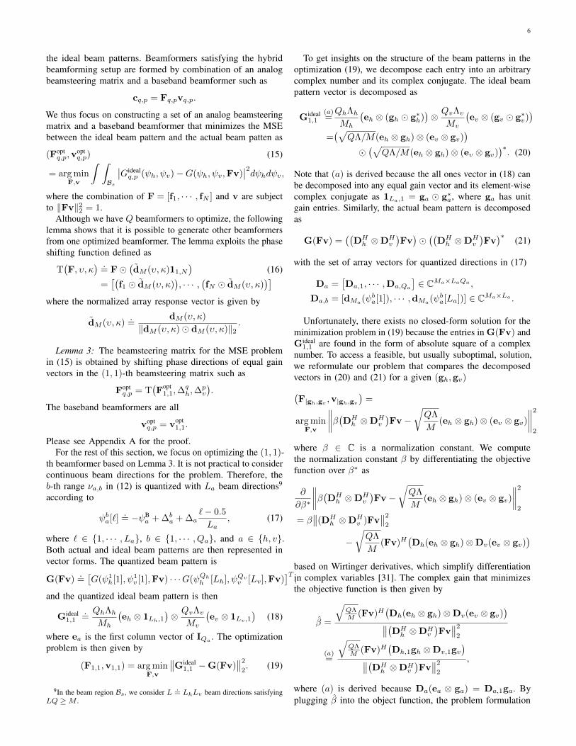
Fig. 6. Normalized beamforming gains GBF(θh, θv , c2,2) with (Mh,Mv) = (16, 8), (Qh, Qv) = (8, 4), N = 4.
C. Final beamformer selection with MSE minimization
The beamformer that generates the beam pattern close tothe (1, 1)-ideal beam pattern is chosen as
c1,1 = F|gh,gvv|gh,gv
where a set of the beamsteering matrix and the basebandbeamformer that accomplishes the minimization objective in(15) is given by12
(gh, gv) = arg mingh,gv
∥∥Gideal1,1 −G(F|gh,gvv|gh,gv )
∥∥2
2(25)
over (gh,gv) ∈ GILh×GILv
. Increasing I and La ensures a largenumber of beamformer candidate for the optimization problemin (15), while it imposes a heavy computational complexity.To construct GILa in (23), we thus consider limited numbersof I and La.
Finally, all other beamformers in the proposed codebookC =
{c1,1 · · · cQh,Qv
}can be derived based on Lemma 3 such
as
cq,p = T(F|gh,gv ,∆
qh,∆
pv
)v|gh,gv . (26)
D. Overlapped beam regions
In most beam alignment approaches, the beamformer generat-ing the largest beamforming gain for data transmission is chosenamong the consecutive beamformers in the overlapped beamregion. Practical beamformers, which are designed based onnon-overlapping beam regions in (11), generate beam patternshaving minimal overlap between neighboring beams. Thismight not be desirable when tying to cover a geographic regionwith adequate quality of service. To alleviate sharp dips betweenconsecutive beams, we thus widen the beam region of eachbeamformer by allowing a guard band Bq,p
.= νhq × νvp , where
νab.= −ψB
a + ∆ba + ∆a
[− γ, 1 + γ
),
∆a is the non-overlapped beam-width of each beamformer in(12), and γ∆a is the overlapped beam-width of the guard band,which is defined by the design parameter γ. Because eachbeamformer covers the widened beam region including the
12Because the codebook is constructed offline, the brute force search in(25) is performed only once and has no impact on system operation.
guard band, an ideal beam pattern may have a low non-zeroreference gain. Thus, the ideal beam pattern is redefined as
Gidealq,p (ψh, ψv) =
QΛ
M(1 + 2γ)21Bq,p(ψh, ψv).
Beamformers alleviating the sharp dips are also computedbased on the proposed codebook design algorithm by pluggingthe redefined beam pattern into the optimization problem.
V. SIMULATION RESULTS
In this section, numerical results are presented to verifythe data rate performances of proposed codebook designalgorithm. In this paper, four RF chains and a six bit phasecontrol register, i.e., N = 4, B = 6, are considered forhybrid beamforming architectures. The beamforming codebookC = {c1,1 · · · cQh,Qv} consisting of Q = QhQv beamformersis designed as in (26). For the minimization problem in (25),the equal gain sets GILh and GILv are defined with parametersLh = 8, Lv = 8, and I = 3. In addition, we consider20 directions in each beam-width νa,b to compute the MSEbetween the beamformer candidate’s beam pattern and the idealbeam pattern.
A. Beam patterns of codebook examples
In Figs. 6 and 7, we compare the beam patterns of theproposed codebook and the codebooks in [8], [14], and the 2DKP codebook in [33]. The ULA codebook in [8] is extendedto a 2D UPA codebook by maximizing a minimum referencegain in each target beam region Bq,p. The codebook in [14]is extended to UPA structures with a single set of equal gainvectors
(gh, gv).=(1d256/Qh,1e,1d256/Qv,1e
). (27)
Finally, the 2D KP codebook is given by Dh × Dv wherethe discrete Fourier transform (DFT) codebook in the domaina ∈ {h, v} is defined as
Da.={dMa
(2π/Qa), · · · ,dMa(2πQa/Qa)
}.
In Fig. 6, we compare the beam patterns of a singlebeamformer by using the reference gain defined as
GBF(θh, θv, cq,p) =∣∣cHq,pdM(π sin θh cos θv, π sin θv
)∣∣2
9
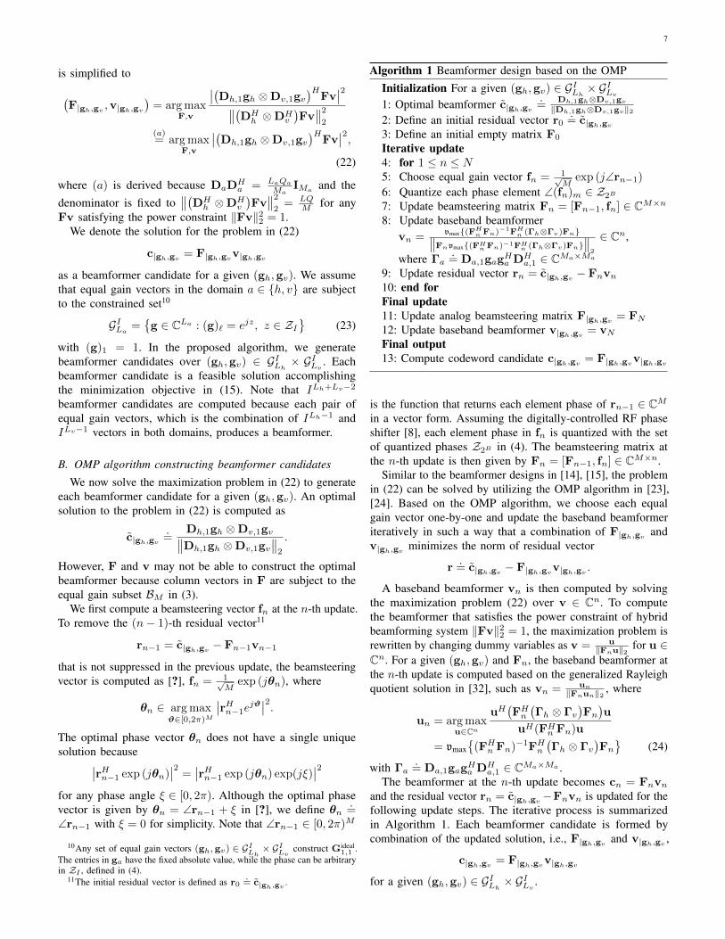
(a) Proposed codebook (Average reference gain 0.553) (b) Proposed codebook with γ = 7.5% (Averagereference gain 0.467)
(c) Codebook in [8] (Average reference gain 0.397) (d) Codebook with gh & gv [14] (Average referencegain 0.440)
Fig. 7. Codebook examples with (Mh,Mv) = (12, 6), (Qh, Qv) = (8, 8), N = 4.
over beam directions (θh, θv) ∈ [−π2 ,π2 )× [−π4 ,
π4 ). In Fig. 7,
we plot beam patterns in each target beam region based on thereference gain GBF(θh, θv, c(q,p)|θh,θv
) such that
(q, p)|θh,θv = arg max(q,p)∈Q
∣∣cHq,pdM(π sin θh cos θv, π sin θv)∣∣2
where Q = {1, · · · , Qh} × {1, · · · , Qv}. As shown in Fig. 6,the proposed codebook can generate higher reference gains thatwill allow the transmitter to efficiently sound mmWave channelsas well as to facilitate highly directional data transmission.In Fig. 7, the mean of the reference gains of the proposedcodebook, the proposed codebook considering the guard band,and the codebooks from [8] and [14] are 0.553, 0.467, 0.397,and 0.440, respectively. Furthermore, it is also shown thatthe proposed codebook in Section IV-D alleviates sharp dipsbetween consecutive beams. Although the beam pattern mayhave lower reference gains compared to the proposed codebookassuming no guard band, the reference gains are much higherthan that of the previously reported codebooks in [8], [14].
At this point, we pause to discuss the difference betweeneach of the beam patterns. First, we consider the codebookin [8]. A beamformer in the codebook of [8] is designedto maximize a minimum reference gain in each target beamregion, defined primarily for the corresponding beamformer.The codebook in [8] can generate beam patterns with uniformreference gains, while the value of reference gains are muchlower than that of the proposed codebook. Beam patterns having
uniform beamforming gains are essential for providing samequality of service to uniformly distributed users, but the lowreference gains may restrict the data rate performance. Next,we consider the codebook in [14]. Each beamformer in theproposed codebook is optimized over beamformer candidatesgenerated using ILh+Lv−2 sets of equal gain vectors (gh,gv) ∈GILh ×G
ILv
, while the codebook in [14] is designed by using asingle set of all ones vectors (gh, gv) in (27). The codebookin [14] is one of several codebook candidates of the proposedalgorithm. Therefore, the proposed codebook suppresses theMSE between the ideal beam patterns and the actual beampatterns better than the beams in [14].
B. Data rate performance
We now evaluate the performance of the codebooks basedon the expected data rate defined as
R = E[
log2
(1 + ρ|hHc|2
) ∣∣ ‖h‖22 = M], (28)
where c is the selected beamformer for data transmissions.The preferred beamformer c in (28) is chosen based on hard-decision beam alignment algorithms [7]–[10]. The data rateperformances of the codebooks are evaluated from MonteCarlo simulations with 10, 000 independent channel realizations.For demonstrations, we consider two channel scenarios basedon the street geometry conditions under ray-like propagationassumptions [27]. In the first scenario, we consider channels
10
SNR ρ (dB)
-10 -5 0 5 10
Da
ta r
ate
R (
bit/s
/Hz)
0
1
2
3
4
5
6
7
8
9
Upper bound in (14)
Proposed codebook
Codebook in [8]
Codebook in [14]
2D KP codebook
(a) (Mh,Mv) = (12, 6), (Qh, Qv) = (8, 4)
SNR ρ (dB)
-10 -5 0 5 10
Data
rate
R (
bit/s
/Hz)
0
1
2
3
4
5
6
7
8
9
Upper bound in (14)
Proposed codebook
Codebook in [8]
Codebook in [14]
2D KP codebook
(b) (Mh,Mv) = (16, 8), (Qh, Qv) = (8, 4)
SNR ρ (dB)
-10 -5 0 5 10
Data
rate
R (
bits/s
/Hz)
0
1
2
3
4
5
6
7
8
9
Upper bound in (14)
Proposed codebook
Codebook in [8]
Codebook in [14]
2D KP codebook
(c) (Mh,Mv) = (20, 10), (Qh, Qv) = (8, 4)
SNR ρ (dB)
-10 -5 0 5 10
Da
ta r
ate
R (
bit/s
/Hz)
0
1
2
3
4
5
6
7
8
9
Upper bound in (14)
Proposed codebook
Codebook in [8]
Codebook in [14]
2D KP codebook
(d) (Mh,Mv) = (24, 12), (Qh, Qv) = (8, 4)
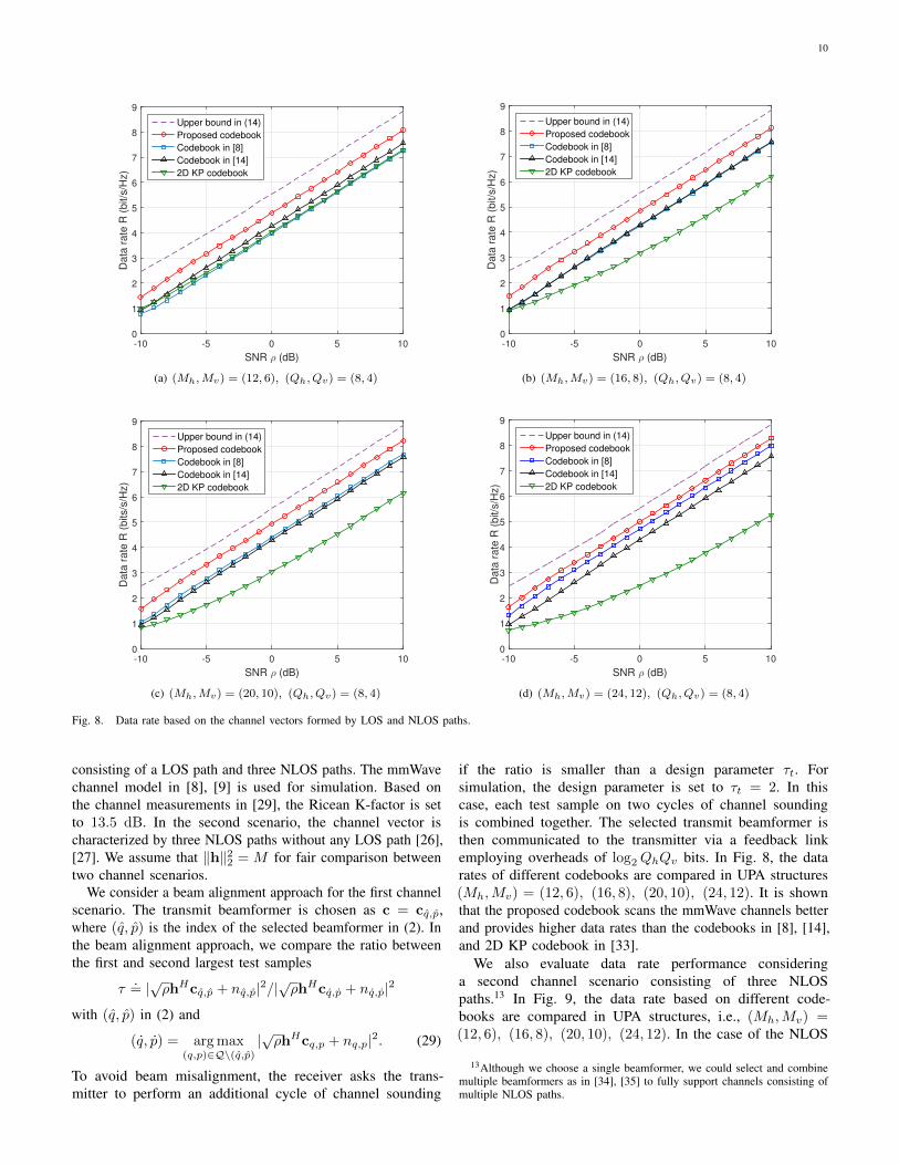
Fig. 8. Data rate based on the channel vectors formed by LOS and NLOS paths.
consisting of a LOS path and three NLOS paths. The mmWavechannel model in [8], [9] is used for simulation. Based onthe channel measurements in [29], the Ricean K-factor is setto 13.5 dB. In the second scenario, the channel vector ischaracterized by three NLOS paths without any LOS path [26],[27]. We assume that ‖h‖22 = M for fair comparison betweentwo channel scenarios.
We consider a beam alignment approach for the first channelscenario. The transmit beamformer is chosen as c = cq,p,where (q, p) is the index of the selected beamformer in (2). Inthe beam alignment approach, we compare the ratio betweenthe first and second largest test samples
τ.= |√ρhHcq,p + nq,p|2/|
√ρhHcq,p + nq,p|2
with (q, p) in (2) and
(q, p) = arg max(q,p)∈Q\(q,p)
|√ρhHcq,p + nq,p|2. (29)
To avoid beam misalignment, the receiver asks the trans-mitter to perform an additional cycle of channel sounding
if the ratio is smaller than a design parameter τt. Forsimulation, the design parameter is set to τt = 2. In thiscase, each test sample on two cycles of channel soundingis combined together. The selected transmit beamformer isthen communicated to the transmitter via a feedback linkemploying overheads of log2QhQv bits. In Fig. 8, the datarates of different codebooks are compared in UPA structures(Mh,Mv) = (12, 6), (16, 8), (20, 10), (24, 12). It is shownthat the proposed codebook scans the mmWave channels betterand provides higher data rates than the codebooks in [8], [14],and 2D KP codebook in [33].
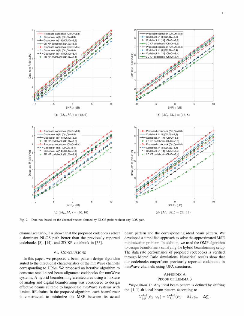
We also evaluate data rate performance consideringa second channel scenario consisting of three NLOSpaths.13 In Fig. 9, the data rate based on different code-books are compared in UPA structures, i.e., (Mh,Mv) =(12, 6), (16, 8), (20, 10), (24, 12). In the case of the NLOS
13Although we choose a single beamformer, we could select and combinemultiple beamformers as in [34], [35] to fully support channels consisting ofmultiple NLOS paths.
11
SNR ρ (dB)
-10 -5 0 5 10
Data
rate
R (
bit/s
/Hz)
1
2
3
4
5
6
7
8
Proposed codebook (Qh,Qv=8,8)
Codebook in [8] (Qh,Qv=8,8)
Codebook in [14] (Qh,Qv=8,8)
2D KP codebook (Qh,Qv=8,8)
Proposed codebook (Qh,Qv=8,4)
Codebook in [8] (Qh,Qv=8,4)
Codebook in [14] (Qh,Qv=8,4)
2D KP codebook (Qh,Qv=8,4)
(a) (Mh,Mv) = (12, 6)
SNR ρ (dB)
-10 -5 0 5 10
Data
rate
R (
bit/s
/Hz)
1
2
3
4
5
6
7
8
9
Proposed codebook (Qh,Qv=8,8)
Codebook in [8] (Qh,Qv=8,8)
Codebook in [14] (Qh,Qv=8,8)
2D KP codebook (Qh,Qv=8,8)
Proposed codebook (Qh,Qv=8,4)
Codebook in [8] (Qh,Qv=8,4)
Codebook in [14] (Qh,Qv=8,4)
2D KP codebook (Qh,Qv=8,4)
(b) (Mh,Mv) = (16, 8)
SNR ρ (dB)
-10 -5 0 5 10
Data
rate
R (
bit/s
/Hz)
1
2
3
4
5
6
7
8
9
Proposed codebook (Qh,Qv=8,8)
Codebook in [8] (Qh,Qv=8,8)
Codebook in [14] (Qh,Qv=8,8)
2D KP codebook (Qh,Qv=8,8)
Proposed codebook (Qh,Qv=8,4)
Codebook in [8] (Qh,Qv=8,4)
Codebook in [14] (Qh,Qv=8,4)
2D KP codebook (Qh,Qv=8,4)
(c) (Mh,Mv) = (20, 10)
SNR ρ (dB)
-10 -5 0 5 10
Data
rate
R (
bit/s
/Hz)
1
2
3
4
5
6
7
8
9
Proposed codebook (Qh,Qv=8,8)
Codebook in [8] (Qh,Qv=8,8)
Codebook in [14] (Qh,Qv=8,8)
2D KP codebook (Qh,Qv=8,8)
Proposed codebook (Qh,Qv=8,4)
Codebook in [8] (Qh,Qv=8,4)
Codebook in [14] (Qh,Qv=8,4)
2D KP codebook (Qh,Qv=8,4)
(d) (Mh,Mv) = (24, 12)
Fig. 9. Data rate based on the channel vectors formed by NLOS paths without any LOS path.
channel scenario, it is shown that the proposed codebooks selecta dominant NLOS path better than the previously reportedcodebooks [8], [14], and 2D KP codebook in [33].
VI. CONCLUSIONS
In this paper, we proposed a beam pattern design algorithmsuited to the directional characteristics of the mmWave channelscorresponding to UPAs. We proposed an iterative algorithm toconstruct small-sized beam alignment codebooks for mmWavesystems. A hybrid beamforming architectures using a mixtureof analog and digital beamforming was considered to designeffective beams suitable to large-scale mmWave systems withlimited RF chains. In the proposed algorithm, each beamformeris constructed to minimize the MSE between its actual
beam pattern and the corresponding ideal beam pattern. Wedeveloped a simplified approach to solve the approximated MSEminimization problem. In addition, we used the OMP algorithmto design beamformers satisfying the hybrid beamforming setup.The data rate performance of proposed codebooks is verifiedthrough Monte Carlo simulations. Numerical results show thatour codebooks outperform previously reported codebooks inmmWave channels using UPA structures.
APPENDIX APROOF OF LEMMA 3
Proposition 1: Any ideal beam pattern is defined by shiftingthe (1, 1)-th ideal beam pattern according to
Gidealq,p (ψh, ψv) = Gideal
1,1 (ψh −∆qh, ψv −∆p
v).
12
(Foptq,p,v
optq,p)
(a)= arg min
F,v
∫ π
−π
∫ π
−π
∣∣Gideal1,1
(ψh −∆q
h, ψv −∆pv
)−G
(ψh, ψv,Fv
)∣∣2dψvdψh(b)= arg min
F,v
∫ π
−π
∫ π
−π
∣∣Gideal1,1
(ψh −∆q
h, ψv −∆pv
)−G
(ψh −∆q
h, ψv −∆pv,T(F,−∆q
h,−∆pv)v)∣∣2dψvdψh. (30)
(Foptq,p,v
optq,p) = arg min
F,v
∫ π−∆qh
−π−∆qh
∫ π−∆pv
−π−∆pv
∣∣Gideal1,1
(φh, φv
)−G
(φh, φv, Fv
)∣∣2dφvdφh= arg min
F,v
∫ π−∆qh
−π−∆qh
[ ∫ −π−π−∆p
v
∣∣Gideal1,1
(φh, φv
)−G
(φh, φv, Fv
)∣∣2dφv +
∫ π−∆pv
−π
∣∣Gideal1,1
(φh, φv
)−G
(φh, φv, Fv
)∣∣2dφv]dφh(a)= arg min
F,v
∫ π−∆qh
−π−∆qh
[ ∫ π
π−∆pv
∣∣Gideal1,1
(φh, φv
)−G
(φh, φv, Fv
)∣∣2dφv +
∫ π−∆pv
−π
∣∣Gideal1,1
(φh, φv
)−G
(φh, φv, Fv
)∣∣2dφv]dφh= arg min
F,v
∫ π
−π
∫ π
−π
∣∣Gideal1,1
(φh, φv
)−G
(φh, φv, Fv
)∣∣2dφvdφh = (Fopt1,1,v
opt1,1). (31)
G(ψh, ψv,Fv
) (a)=∣∣∣(dM (ψh + ∆q
h, ψv + ∆pv)� dM (−∆q
h,−∆pv))H(
F� 1M,N
)v∣∣∣2
(b)=∣∣∣(dM (ψh + ∆q
h, ψv + ∆pv)� dM (−∆q
h,−∆pv))H(
F�((
dM (∆qh,∆
pv)11,N
)�(dM (−∆q
h,−∆pv)11,N
)))v∣∣∣2
(c)=∣∣∣(dM (ψh + ∆q
h, ψv + ∆pv)� dM (−∆q
h,−∆pv))H(
T(F,∆q
h,∆pv
)� dM (−∆q
h,−∆pv)11,N
)v∣∣∣2
=∣∣∣((dM (ψh + ∆q
h, ψv + ∆pv)� dM (−∆q
h,−∆p))H[
T(F,∆q
h,∆pv
):,1� dM (−∆q
h,−∆pv), · · · ,T
(F,∆q
h,∆pv
):,N� dM (−∆q
h,−∆pv)])
v∣∣∣2
(d)=∣∣∣dHM (ψh + ∆q
h, ψv + ∆pv)T
(F,∆q
h,∆pv
)v∣∣∣2 = G
(ψh + ∆q
h, ψv + ∆pv,T
(F,∆q
h,∆pv
)v). (32)
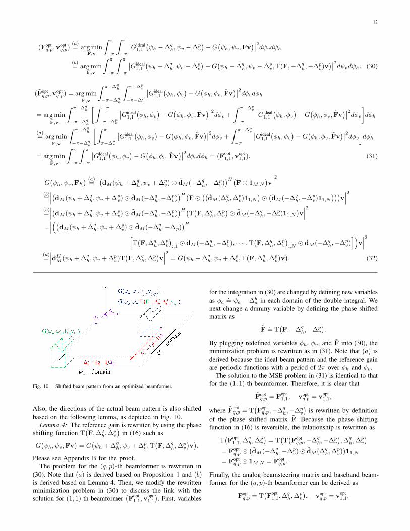
Fig. 10. Shifted beam pattern from an optimized beamformer.
Also, the directions of the actual beam pattern is also shiftedbased on the following lemma, as depicted in Fig. 10.
Lemma 4: The reference gain is rewritten by using the phaseshifting function T
(F,∆q
h,∆pv
)in (16) such as
G(ψh, ψv,Fv
)= G
(ψh + ∆q
h, ψv + ∆pv,T
(F,∆q
h,∆pv
)v).
Please see Appendix B for the proof.The problem for the (q, p)-th beamformer is rewritten in
(30). Note that (a) is derived based on Proposition 1 and (b)is derived based on Lemma 4. Then, we modify the rewrittenminimization problem in (30) to discuss the link with thesolution for (1, 1)-th beamformer
(Fopt
1,1,vopt1,1
). First, variables
for the integration in (30) are changed by defining new variablesas φa
.= ψa −∆b
a in each domain of the double integral. Wenext change a dummy variable by defining the phase shiftedmatrix as
F.= T
(F,−∆q
h,−∆pv
).
By plugging redefined variables φh, φv, and F into (30), theminimization problem is rewritten as in (31). Note that (a) isderived because the ideal beam pattern and the reference gainare periodic functions with a period of 2π over φh and φv .
The solution to the MSE problem in (31) is identical to thatfor the (1, 1)-th beamformer. Therefore, it is clear that
Foptq,p = Fopt
1,1, voptq,p = vopt
1,1,
where Foptq,p = T
(Foptq,p,−∆q
h,−∆pv
)is rewritten by definition
of the phase shifted matrix F. Because the phase shiftingfunction in (16) is reversible, the relationship is rewritten as
T(Fopt
1,1,∆qh,∆
pv
)= T
(T(Foptq,p,−∆q
h,−∆pv
),∆q
h,∆pv
)= Fopt
q,p �(dM (−∆q
h,−∆pv)� dM (∆q
h,∆pv))11,N
= Foptq,p � 1M,N = Fopt
q,p.
Finally, the analog beamsteering matrix and baseband beam-former for the (q, p)-th beamformer can be derived as
Foptq,p = T
(Fopt
1,1,∆qh,∆
pv
), vopt
q,p = vopt1,1.
13
APPENDIX BPROOF OF LEMMA 4
The reference gain G(ψh, ψv,Fv
)is rewritten by using the
phase shifting functions T(F,∆q
h,∆pv
)in (32). Note that (a)
of (32) is derived based on the property of array vectors
dM (ψ1 + ψ3, ψ2 + ψ4) = dM (ψ1, ψ2)� dM (ψ3, ψ4),
(b) is derived because 1M,N is decomposed as
1M,N =(dM (ψ1, ψ2)� dM (−ψ1,−ψ2)
)11,N
=(dM (ψ1, ψ2)11,N
)�(dM (−ψ1,−ψ2)11,N
),
and (c) is rewritten by the definition of the phase shiftingfunction T
(F,∆q
h,∆pv
)in Lemma 3 and the associative
property of the Hadamard product
A� (B�C) = (A�B)�C
for arbitrary matrices of the same size. Finally, (d) is derivedbased on the formulation between vectors a = [a1, · · · , aM ]T ,b = [b1, · · · , bM ]T , and c = [c1, · · · , cM ]T ,
(a� b)H(c� b) =
M∑m=1
a∗mcm|bm|2
= aHc,
which holds with the condition of |bm|2 = 1 for allm ∈ {1, · · · ,M}. Note that (d) satisfies this conditionbecause each element of dM (−∆q
h,−∆pv) has a unit gain,
i.e.,∣∣(dM (−∆q
h,−∆pv))m
∣∣2 = 1 for all m ∈ {1, · · · ,M}.
REFERENCES
[1] J. Song, J. Choi, and D. J. Love, “Codebook design for hybridbeamforming in millimeter wave systems,” in Proceedings of IEEEInternational Conference on Communications, Jun. 2015.
[2] A. Ghosh, T. A. Thomas, M. C. Cudak, R. Ratasuk, P. Moorut, F. W.Vook, T. S. Rappaport, G. R. MacCartney, S. Sun, and S. Nie, “Millimeterwave enhanced local area systems: a high data rate approach for futurewireless networks,” IEEE Journal on Selected Areas in Communications,vol. 32, no. 6, pp. 1152–1163, Jun. 2014.
[3] T. S. Rappaport, S. Sun, R. Mayzus, H. Zhao, Y. Azar, K. Wang, G. N.Wong, J. K. Schulz, M. Samimi, and F. Gutierrez, “Millimeter wavemobile communications for 5G cellular: It will work!” IEEE Access,vol. 1, pp. 335–349, May 2013.
[4] Z. Pi and F. Khan, “An introduction to millimeter-wave mobile broadbandsystems,” IEEE Communications Magazine, vol. 49, no. 6, pp. 101–107,Jun. 2011.
[5] W. Roh, J.-Y. Seol, J. Park, B. Lee, J. Lee, Y. Kim, J. Cho, K. Cheun, andF. Aryanfar, “Millimeter-wave beamforming as an enabling technologyfor 5G cellular communications: theoretical feasibility and prototyperesults,” IEEE Communications Magazine, vol. 52, no. 2, pp. 106–113,Feb. 2014.
[6] R. C. Hansen, Phased array antennas, 2nd ed. Hoboken: Wiley-Interscience, 2009.
[7] S. Hur, T. Kim, D. J. Love, J. V. Krogmeier, T. A. Thomas, and A. Ghosh,“Multilevel millimeter wave beamforming for wireless backhaul,” inProceedings of IEEE Global Telecommunications Conference Workshops,Dec. 2011.
[8] ——, “Millimeter wave beamforming for wireless backhaul and accessin small cell networks,” IEEE Transactions on Communications, vol. 61,no. 10, pp. 4391–4403, Oct. 2013.
[9] J. Song, S. G. Larew, D. J. Love, T. A. Thomas, and A. Ghosh,“Millimeter wave beam-alignment for dual-polarized outdoor MIMOsystems,” in Proceedings of IEEE Global Telecommunications ConferenceWorkshops, Dec. 2013.
[10] J. Song, J. Choi, S. G. Larew, D. J. Love, T. A. Thomas, and A. Ghosh,“Adaptive millimeter wave beam alignment for dual-polarized MIMOsystems,” IEEE Transactions on Wireless Communications, vol. 14, no. 11,pp. 6283–6296, Nov. 2015.
[11] IEEE, PHY/MAC complete proposal specification (TGad D0.1), IEEE802.11-10/0433r2 Std., 2012.
[12] S. Sun, T. S. Rappaport, R. W. Heath, A. Nix, and S. Rangan, “MIMOfor millimeter-wave wireless communications: beamforming, spatialmultiplexing, or both?” IEEE Communications Magazine, vol. 52, no. 12,pp. 110–121, 2014.
[13] S. Noh, M. D. Zoltowski, and D. J. Love, “Multi-resolution codebookand adaptive beamforming sequence design for millimeter wave beamalignment,” submitted to IEEE Transactions on Wireless Communications,2015.
[14] A. Alkhateeb, O. E. Ayach, and R. W. Heath, “Channel estimation andhybrid precoding for millimeter wave cellular systems,” IEEE Journalof Selected Topics in Signal Processing, vol. 8, no. 5, pp. 831–846, Oct.2014.
[15] O. E. Ayach, S. Rajagopal, S. Abu-Surra, Z. Pi, and R. W. Heath,“Spatially sparse precoding in millimeter wave MIMO systems,” IEEETransactions on Wireless Communications, vol. 13, no. 3, pp. 1499–1513,Mar. 2014.
[16] Y. H. Nam, B. L. Ng, K. Sayana, Y. Li, J. Zhang, Y. Kim, and J. Lee,“Full-dimension MIMO for next generation cellular technology,” IEEECommunications Magazine, vol. 51, no. 6, pp. 172–179, Jun. 2013.
[17] D. J. Love, R. W. Heath, V. K. Lau, D. Gesbert, B. D. Rao, and M. An-drews, “An overview of limited feedback in wireless communicationsystems,” IEEE Journal on Selected Areas in Communications, vol. 26,no. 8, pp. 1341–1365, 2008.
[18] B. Hassibi and B. M. Hochwald, “How much training is needed inmultiple-antenna wireless links?” IEEE Transactions on InformationTheory, vol. 49, no. 4, pp. 951–963, Apr. 2003.
[19] W. Santipach and M. L. Honig, “Optimization of training and feedbackoverhead for beamforming over block fading channels,” IEEE Trans-actions on Information Theory, vol. 56, no. 12, pp. 6103–6115, Dec.2010.
[20] W. U. Bajwa, J. Haupt, A. M. Sayeed, and R. Nowak, “Compressedchannel sensing: a new approach to estimating sparse multipath channels,”Proceedings of the IEEE, vol. 98, no. 6, pp. 1058–1076, Jun. 2010.
[21] D. Ramasamy, S. Venkateswaran, and U. Madhow, “Compressiveadaptation of large steerable arrays,” in UCSD Information Theory andApplications Workshop, Feb. 2012.
[22] T. Kim and D. J. Love, “Virtual AoA and AoD estimation for sparsemillimeter wave MIMO channels,” in Proceedings of IEEE InternationalWorkshop on Signal Processing Advances in Wireless Communications,Jun. 2015.
[23] J. A. Tropp and A. C. Gilbert, “Signal recovery from random mea-surements via orthogonal matching pursuit,” IEEE Transactions onInformation Theory, vol. 51, no. 1, pp. 188–209, Dec. 2005.
[24] L. Rebollo-Neira and D. Lowe, “Optimized orthogonal matching pursuitapproach,” IEEE Signal Processing Letters, vol. 9, no. 4, pp. 137–140,Dec. 2005.
[25] T. S. Rappaport, E. Ben-Dor, J. N. Murdock, and Y. Qiao, “38 GHz and60 GHz angle-dependent propagation for cellular & peer-to-peer wirelesscommunications,” in Proceedings of IEEE International Conference onCommunications, Jun. 2012.
[26] M. R. Akdeniz, Y. Liu, M. K. Samimi, S. Sun, S. Rangan, T. S. Rappaport,and E. Erkip, “Millimeter wave channel modeling and cellular capacityevaluation,” IEEE Journal on Selected Areas in Communications, vol. 32,no. 6, pp. 1164–1179, Jun. 2014.
[27] H. Zhang, S. Venkateswaran, and U. Madhow, “Channel modeling andMIMO capacity for outdoor millimeter wave links,” in Proceedings ofIEEE Wireless Communications and Networking Conference, Apr. 2010.
[28] B. Clerckx, C. Craeye, D. Vanhoenacker-Janvier, and C. Oestges, “Impactof antenna coupling on 2 times; 2 MIMO communications,” Proceedingsof IEEE Vehicular Technology Conference, vol. 56, no. 3, pp. 1009–1018,May 2007.
[29] Z. Muhi-Eldeen, L. Ivrissimtzis, and M. Al-Nuaimi, “Modelling and mea-surements of millimeter wavelength propagation in urban environments,”IET Microwaves Antennas & Propagation, vol. 4, no. 9, pp. 1300–1309,Sep. 2010.
[30] A. Sayeed and J. Brady, “Beamspace MIMO for high-dimensionalmultiuser communication at millimeter-wave frequencies,” in Proceedingsof IEEE Global Telecommunications Conference, Dec. 2013.
[31] R. Remmert, Theory of complex functions. New York: Springer-Verlag,1991.

14
[32] M. Borga, “Learning multidimensional signal processing,” Ph.D. disser-tation, Linkping University, Linkping, Sweden, 1998, SE-581 83.
[33] R1-150560, Codebook for 2D antenna arrays, 3GPP TSG RAN WG1#80 Std., Feb. 2015.
[34] J. Choi, K. Lee, D. J. Love, T. Kim, and R. W. Heath, “Advancedlimited feedback designs for FD-MIMO using uniform planar arrays,”in Proceedings of IEEE Global Telecommunications Conference, Dec.2015.
[35] J. Song, J. Choi, K. Lee, T. Kim, J. Y. Seol, and D. J. Love, “Advancedquantizer designs for FD-MIMO systems using uniform planar arrays,”in Proceedings of IEEE Global Telecommunications Conference, Dec.2016.