Committee on NFPA 2 - National Fire Protection Association · NFPA 54, ANSI Z223.1–2009 National...
296
Committee on NFPA 2 M E M O R A N D U M TO: NFPA Technical Committee on Hydrogen Technology FROM: Jeanne Moreau DATE: June 4, 2010 SUBJECT: NFPA 2 F10 ROC Letter Ballot The ROC letter ballot for NFPA 2 is attached. The ballot is for formally voting on whether or not you concur with the committee’s actions on the proposals. Reasons must accompany all negative and abstention ballots. Please do not vote negatively because of editorial errors. However, please bring such errors to my attention for action. Please complete and return your ballot as soon as possible but no later than Friday, June 18, 2010 . As noted on the ballot form, please return the ballot to Jeanne Moreau-Correia either via e-mail to [email protected] or via fax to 617-984-7110. The return of ballots is required by the Regulations Governing Committee Projects. Attachment: Comments
Transcript of Committee on NFPA 2 - National Fire Protection Association · NFPA 54, ANSI Z223.1–2009 National...
Committee on NFPA 2
M E M O R A N D U M
TO: NFPA Technical Committee on Hydrogen Technology
FROM: Jeanne Moreau
DATE: June 4, 2010
SUBJECT: NFPA 2 F10 ROC Letter Ballot
The ROC letter ballot for NFPA 2 is attached. The ballot is for formally voting on
whether or not you concur with the committee’s actions on the proposals. Reasons must
accompany all negative and abstention ballots.
Please do not vote negatively because of editorial errors. However, please bring such
errors to my attention for action.
Please complete and return your ballot as soon as possible but no later than Friday, June
18, 2010. As noted on the ballot form, please return the ballot to Jeanne Moreau-Correia
either via e-mail to [email protected] or via fax to 617-984-7110.
The return of ballots is required by the Regulations Governing Committee Projects.
Attachment: Comments
Report on Comments – November 2010 NFPA 2_______________________________________________________________________________________________2-1 Log #CC15
_______________________________________________________________________________________________Technical Committee on Hydrogen Technology,
2-1Revise 13.2.6.3 and 13.3.1.1.2 and all other related paragraphs to replace “NFPA 5000” and
"building code" with the words “adopted building code.”The change is made to create consistency with remainder of document.
_______________________________________________________________________________________________2-2 Log #CC16
_______________________________________________________________________________________________Technical Committee on Hydrogen Technology,
2-1Remove superfluous references to LNG, CNG, and LPG as follows:
3.3.55.1 Cargo Transport Container. A mobile unit designed to transport LNG, CNG, GH2, or LH2. [52, 2010]3.3.55.3 Fuel Supply Container. A container mounted on a vehicle to store LNG, CNG, LH2, or GH2 as the fuel supply
to the vehicle. [52, 2010]3.3.283 Vaporizer. A device other than a container that receives LNG or LH2 in liquid form and adds sufficient heat to
convert the liquid to a gaseous , or a device used to add heat to LNG or LH2 for the purpose of saturating LNG orLH2[52:2010]
11.3.1.13 Dispenser Installations Beneath Canopies. Where [LH2] [CNG or LNG] dispensers are installed beneath acanopy or enclosure, either the canopy or enclosure shall be designed to prevent accumulation or entrapment ofignitable vapors or all electrical equipment installed beneath the canopy or enclosure shall be suitable for Class I,Division 2 hazardous (classified) locations. [30A:12.4]
11.3.1.16 Dispensing Devices. Dispensing devices for CNG, LNG, [[and] LP-Gas [and LH2] shall be listed. [ 12.2.3]3.3.216.8 Service Pressure. The settled gas pressure at a uniform gas temperature of 70°F (21°C) in CNG systems,
and at 59°F (15°C) for GH2 systems when the equipment is fully charged with gas. [52, 2010]A.10.3.1.11.9 As a precaution to keep pressure relief devices in reliable operating condition and to avoid damage,
care should be taken in the handling or storage of CNG or hydrogen [GH2] containers.Care also should be exercised to avoid plugging by paint or other dirt accumulation in pressure relief device channels orother parts that could interfere with the functioning of the device. [52:A.9.16.4]
13.3.2.1.1.1 Piping for natural gas, compressed natural gas, LPG or other liquid fuels shall be in accordance withNFPA 54, National Fuel Gas Code, NFPA 58, Liquefied Petroleum Gas Code, or NFPA 30, Flammable and CombustibleLiquids Code, as applicable. [55:12.3.2.8.4.1]
3.3.111 Fuel Line. The pipe, tubing, or hose on a vehicle, including all related fittings, through which natural gas orhydrogen passes. [52, 2010]
3.3.263.4.2 Gas Detection System. One or more sensors capable of detecting natural gas or hydrogen at specifiedconcentrations and activating alarms and safety systems. [52, 2010]
This removes superfluous references to non-hydrogen liquids and gases.
1Printed on 6/1/2010

Report on Comments – November 2010 NFPA 2_______________________________________________________________________________________________2-3 Log #CC17
_______________________________________________________________________________________________Technical Committee on Hydrogen Technology,
2-1Replace, where appropriate, the use of the references to NFPA 101, with the “adopted building
code."
This would create consistency with the remainder of document.
_______________________________________________________________________________________________2-4 Log #65
_______________________________________________________________________________________________Larry L. Fluer, Fluer, Inc. / Rep. Compressed Gas Association
2-1Revise text as follows:
This code shall apply to the production, storage, transfer, and use of hydrogen in all occupancies and on allpremises.
The term “occupancies” implies that the applicability of the document is limited to areas that areclassified as an occupiable area within the context of code that regulate circumstances integral to buildings or indooruses. Provisions of NFPA 2 apply to areas and conditions outside of buildings where the term premises is appropriate.
_______________________________________________________________________________________________2-5 Log #CC8
_______________________________________________________________________________________________Technical Committee on Hydrogen Technology,
2-1Revise 1.3.4(1) as follows:
(1) Onboard vehicle or mobile equipment components or systems, including the onboard GH2 or LH2 fuel supply, otherthan those required in Chapters 9 through 25.
Having the provision not exclude the fuel supply (including forklifts) if required by Chapters 9 to 20would impact the MAQ limits established in Chapter 6. This implications of this were not well understood in the earlydevelopment of NFPA 2. Now that that document has been more fully developed the document should not retain suchan allowance. A similar concept has been utilized for MAQ provisions in NFPA 5000, Table 34.1.3.1, footnote d.Mobile equipment was added to this to allow for the possibility for hydrogen-powered equipment.
Referencing chapter 9 for the second part of this requirement is not appropriate. This is probably a fallout of early workdone by the fundamentals task group and was included before Chapter 9 was reserved for explosions. Chapters 21-25,as referenced in the ROP draft, do not currently exist.
2Printed on 6/1/2010
Report on Comments – November 2010 NFPA 2_______________________________________________________________________________________________2-6 Log #66
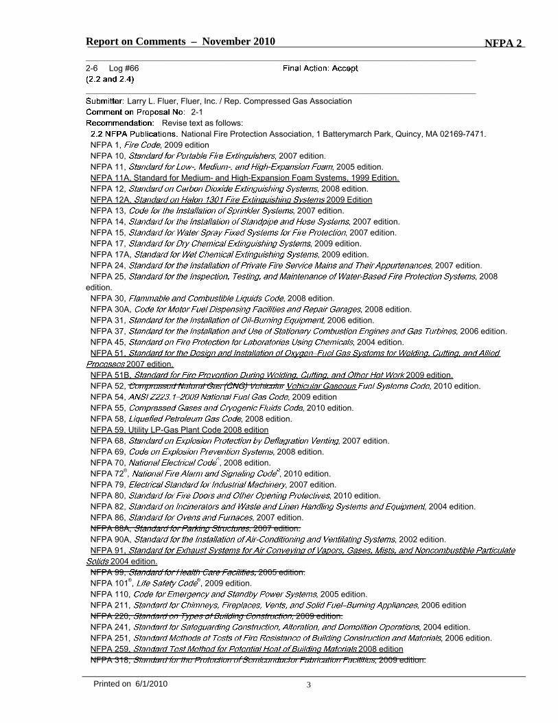
_______________________________________________________________________________________________Larry L. Fluer, Fluer, Inc. / Rep. Compressed Gas Association
2-1Revise text as follows:
National Fire Protection Association, 1 Batterymarch Park, Quincy, MA 02169-7471.NFPA 1, , 2009 editionNFPA 10, , 2007 edition.NFPA 11, , 2005 edition.NFPA 11A, Standard for Medium- and High-Expansion Foam Systems, 1999 Edition.NFPA 12, , 2008 edition.NFPA 12A, 2009 EditionNFPA 13, , 2007 edition.NFPA 14, , 2007 edition.NFPA 15, , 2007 edition.NFPA 17, , 2009 edition.NFPA 17A, , 2009 edition.NFPA 24, , 2007 edition.NFPA 25, , 2008
edition.NFPA 30, , 2008 edition.NFPA 30A, , 2008 edition.NFPA 31, , 2006 edition.NFPA 37, , 2006 edition.NFPA 45, , 2004 edition.NFPA 51,
2007 edition.NFPA 51B, 2009 edition.NFPA 52, , 2010 edition.NFPA 54, , 2009 editionNFPA 55, , 2010 edition.NFPA 58, , 2008 edition.NFPA 59, Utility LP-Gas Plant Code 2008 editionNFPA 68, , 2007 edition.NFPA 69, , 2008 edition.NFPA 70, , 2008 edition.NFPA 72®, , 2010 edition.NFPA 79, , 2007 edition.NFPA 80, , 2010 edition.NFPA 82, , 2004 edition.NFPA 86, , 2007 edition.NFPA 88A, , 2007 edition.NFPA 90A, , 2002 edition.NFPA 91,
2004 edition.NFPA 99, 2005 edition.NFPA 101®, ®, 2009 edition.NFPA 110, , 2005 edition.NFPA 211, , 2006 editionNFPA 220, 2009 edition.NFPA 241, , 2004 edition.NFPA 251, , 2006 edition.NFPA 259, 2008 editionNFPA 318, , 2009 edition.
3Printed on 6/1/2010

Report on Comments – November 2010 NFPA 2
NFPA 496, , 2008 edition.NFPA 497,
, 2008 edition.NFPA 484 2009 editionNFPA 502, , 2008 edition.NFPA 704, , 2007 edition.NFPA 750, , 2006 edition.NFPA 801, , 2008 edition.NFPA 820, , 2008 edition.NFPA 853, , 2007 edition.NFPA 914, 2007 edition.NFPA 921, 2008 edition.NFPA 1962, Standard for the Inspection, Care, and Use of Fire Hose, Couplings, and Nozzles and the Service Testing
of Fire Hose, 2008 Edition. NFPA 2001, 2008 edition.®, ®, 2009 edition.
NFPA 1, , 2009 editionNFPA 101®, Life Safety Code®, 2009 edition.NFPA 13, Code for the Installation of Sprinkler Systems, 2007 edition.NFPA 30, Flammable and Combustible Liquids Code, 2008 edition.NFPA 30A, Code for Motor Fuel Dispensing Facilities and Repair Garages, 2008 edition.NFPA 45, Standard on Fire Protection for Laboratories Using Chemicals, 2004 edition.NFPA 52, , 2010 edition.NFPA 54, ANSI Z223.1–2009 National Fuel Gas Code, 2009 editionNFPA 55, Compressed Gases and Cryogenic Fluids Code, 2010 edition.NFPA 58, Liquefied Petroleum Gas Code, 2008 edition.NFPA 70, , 2008 edition.NFPA 80, Standard for Fire Doors and Other Opening Protectives, 2010 edition.NFPA 86, Standard for Ovens and Furnaces, 2007 edition.NFPA 88A, Standard for Parking Structures, 2007 edition.NFPA 88B, Standard for Repair Garages, 1997 Edition.NFPA 91,
2004 edition.NFPA 99, Standard for Health Care Facilities, 2005 edition.NFPA 220, Standard on Types of Building Construction, 2009 edition.NFPA 318, Standard for the Protection of Semiconductor Fabrication Facilities, 2009 edition.NFPA 801, Standard for Fire Protection for Facilities Handling Radioactive Materials, 2008 edition.NFPA 820, Standard for Fire Protection in Wastewater Treatment and Collection Facilities, 2008 edition.NFPA 853, Standard for the Installation of Stationary Fuel Cell Power Systems, 2007 edition.NFPA 914, Code for Fire Protection of Historic Structures, 2007 edition.NFPA 921, Guide for Fire and Explosion Investigations, 2008 edition.NFPA 1925, Standard on Marine Fire-Fighting Vessels, 2008 Edition.
®, ®, 2009 edition.The references that have been added are found in the following sections. There may be other
sections in which these same references are used:
******Insert 2_L66_Tb_S******
References that have been deleted are not referenced within the body of the code although they may be referenced inan informational annex. References used in informational Annexes should be listed in Annex K. NFPA documents thatare used as informational documents within source documents for extract purposes are also to be included in Annex K.A companion public comment has been issued to address the concerns of Annex K.
4Printed on 6/1/2010

ROC/F2010/NFPA 2/Log #66/Table_Sub
3.3.46.1 NFPA 259, Standard Test Method for Potential Heat of Building Materials 2008 edition
7.1.4.1.12.1 (A) NFPA 484, Standard for Combustible Metals 2009 edition
11.4.3.4.3.2 (D) NFPA 59, Utility LP-Gas Plant Code 2008 edition
16.3.2.1.9.2(11) NFPA 2001, Standard on Clean Agent Fire Extinguishing Systems
16.3.2.1.9.2 (3) NFPA 12A Standard on Halon 1301 Fire Extinguishing Systems 2009 Edition
16.3.2.1.9.3 NFPA 91, Standard for Exhaust Systems for
Air Conveying of Vapors, Gases, Mists, and Noncombustible Particulate
Solids 2004 edition.
19.3.2.5.1 NFPA 51B Standard for Fire Prevention During Welding, Cutting, and Other Hot
Work 2009 Edition
19.3.2.5.2 NFPA 51 Standard for the Design and Installation of Oxygen–Fuel Gas Systems
for Welding, Cutting, and Allied Processes 2007 Edition

Report on Comments – November 2010 NFPA 2
_______________________________________________________________________________________________2-7 Log #53
_______________________________________________________________________________________________Bob Eugene, Underwriters Laboratories Inc.
2-1
ANSI A13.1, Scheme for Identification of Piping Systems, 1996.ANSI/IAS NGV 4.4 , 1999 Edition.ANSI C2, , 2007.ANSI CSA FC.1, American National Standard for Fuel Cell Power Systems, 2004.ANSI/UL 723, Tests for Surface Burning Characteristics of Building Materials, 2003.ANSI Z535.1, , 2006. (ANSI Z535.2, , 2007. (ANSI Z535.3, , 2007. (ANSI Z535.4, , 2007. (ANSI Z9.5, .
UL Publications.Underwriters Laboratories, Inc., 333 Pfingsten Road, Northbrook, IL 60062-2096.ANSI/UL 723, Tests for Surface Burning Characteristics of Building Materials, 2008.UL 429, Electrically Operated Valves, 2009ANSI/UL 2085, Protected Aboveground Tanks for Flammable and Combustible Liquids, 1997, Revised 1999K.1.2.xx UL Publications.Underwriters Laboratories, Inc., 333 Pfingsten Road, Northbrook, IL 60062-2096.UL 429, Electrically Operated Valves, 2009.
Provide separate subsections in 2.3 and K.1.2 to reference UL standards. ANSI/UL 723 is referencedin 3.3.46.1, 16.3.2.1.6.2, 16.3.2.1.6.4, 16.3.2.1.5.2 and 16.3.2.1.7.1. ANSI/UL 2085 is referenced in 3.3.264.1.1. UL 429is referenced in Table A.15.3.1.1.10.9.
_______________________________________________________________________________________________2-8 Log #3
_______________________________________________________________________________________________Norman Newhouse, Lincoln Composites
2-1Add text to read as follows:
ASME Boiler and Pressure Vessel Code, Section X, Fiber-Reinforced Plastic Pressure Vessels, 2010.ASME has developed and approved Code revisions in Section X per Ballot #09-1570RC1 for Record
#08-317 to address storage of hydrogen at high pressures. This approved Code Revision will be published in July 2010.Note: ASME Section X (2007), with its current requirements, also allows hydrogen storage in composite vessels, but
at lower pressures than the newly approved revision.
Currently, composite storage vessels are marked as reserved in NFPA 2 paragraph10.3.1.3.3.4 and the TC believes that it is premature to insert this material into NFPA 2.
5Printed on 6/1/2010
Report on Comments – November 2010 NFPA 2_______________________________________________________________________________________________2-9 Log #67
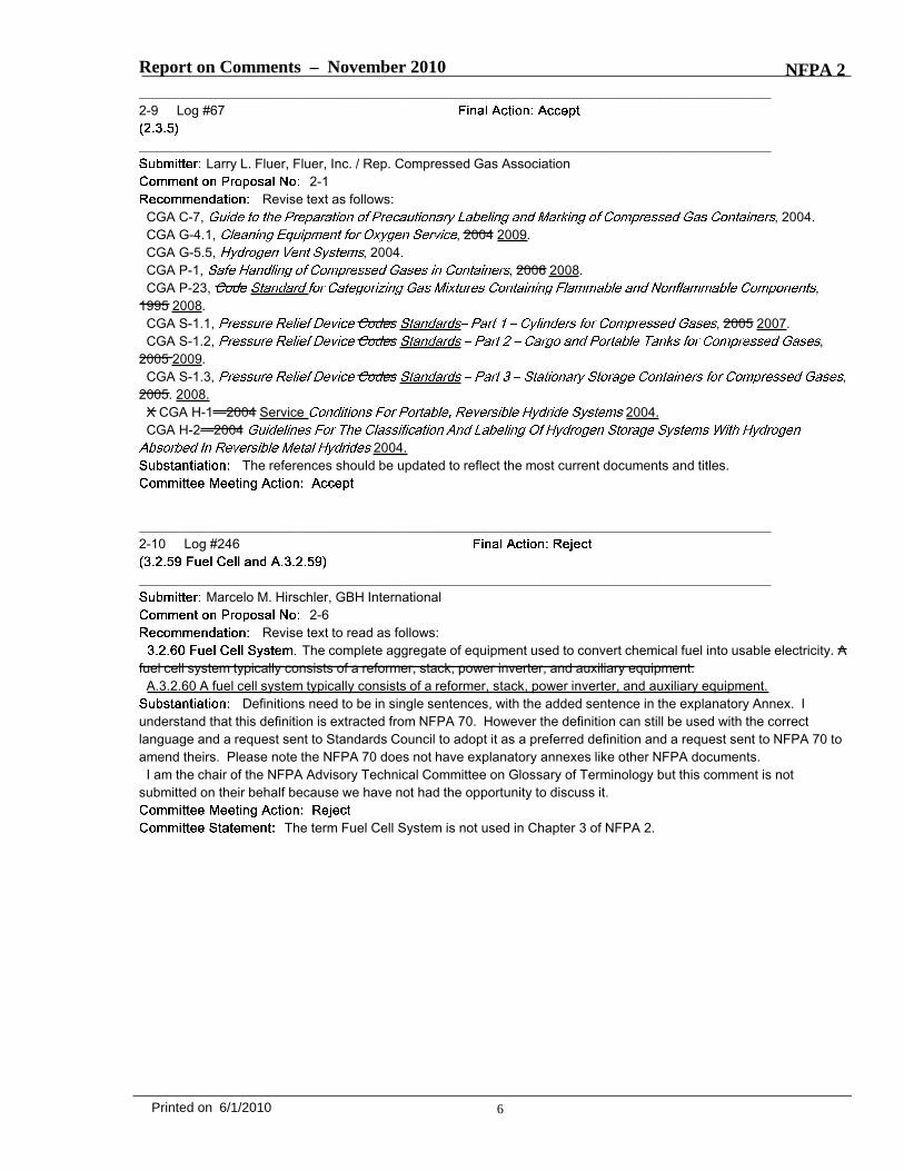
_______________________________________________________________________________________________Larry L. Fluer, Fluer, Inc. / Rep. Compressed Gas Association
2-1Revise text as follows:
CGA C-7, , 2004.CGA G-4.1, , 2004 2009.CGA G-5.5, , 2004.CGA P-1, , 2006 2008.CGA P-23, ,
1995 2008.CGA S-1.1, , 2005 2007.CGA S-1.2, ,
2005 2009.CGA S-1.3, ,
2005. 2008.X CGA H-1—2004 Service 2004.CGA H-2—2004
2004.The references should be updated to reflect the most current documents and titles.
_______________________________________________________________________________________________2-10 Log #246
_______________________________________________________________________________________________Marcelo M. Hirschler, GBH International
2-6Revise text to read as follows:
The complete aggregate of equipment used to convert chemical fuel into usable electricity. Afuel cell system typically consists of a reformer, stack, power inverter, and auxiliary equipment.
A.3.2.60 A fuel cell system typically consists of a reformer, stack, power inverter, and auxiliary equipment.Definitions need to be in single sentences, with the added sentence in the explanatory Annex. I
understand that this definition is extracted from NFPA 70. However the definition can still be used with the correctlanguage and a request sent to Standards Council to adopt it as a preferred definition and a request sent to NFPA 70 toamend theirs. Please note the NFPA 70 does not have explanatory annexes like other NFPA documents.
I am the chair of the NFPA Advisory Technical Committee on Glossary of Terminology but this comment is notsubmitted on their behalf because we have not had the opportunity to discuss it.
The term Fuel Cell System is not used in Chapter 3 of NFPA 2.
6Printed on 6/1/2010
Report on Comments – November 2010 NFPA 2_______________________________________________________________________________________________2-11 Log #247
_______________________________________________________________________________________________Marcelo M. Hirschler, GBH International
2-6Revise text to read as follows:
An electrochemical system that consumes fuel to produce an electric current. The main chemicalreaction used in a fuel cell for producing electric power is not combustion. However, there may be sources ofcombustion used within the overall fuel cell system such as reformers/fuel processors.
A.3.2.59 However, there may be sources of combustion used within the overall fuel cell system such as reformers/fuelprocessors.
Definitions need to be in single sentences, with the added sentence in the explanatory Annex. Iunderstand that this definition is extracted from NFPA 70. However the definition can still be used with the correctlanguage and a request sent to Standards Council to adopt it as a preferred definition and a request sent to NFPA 70 toamend theirs. Please note the NFPA 70 does not have explanatory annexes like other NFPA documents.
I am the chair of the NFPA Advisory Technical Committee on Glossary of Terminology but this comment is notsubmitted on their behalf because we have not had the opportunity to discuss it.
The term Fuel Cell is not used in Chapter 3 of NFPA 2.
_______________________________________________________________________________________________2-12 Log #233
_______________________________________________________________________________________________Marcelo M. Hirschler, GBH International
3-6Revise text to read as follows:
. A fuel cell generator of electricity that is not fixed in place. A portableappliance utilizes a cord and plug connection to a grid-isolated load and has an integral fuel supply.
A.3.2.83.4 A portable appliance utilizes a cord and plug connection to a grid-isolated load and has an integral fuelsupply.
Definitions need to be in single sentences, with the added sentence in the explanatory Annex. Iunderstand that this definition is extracted from NFPA 853. However the definition can still be used with the correctlanguage and a request sent to Standards Council to adopt it as a preferred definition and a request sent to NFPA 853to amend theirs.
I am the chair of the NFPA Advisory Technical Committee on Glossary of Terminology but this comment is notsubmitted on their behalf because we have not had the opportunity to discuss it.
The committee believes that the reader is better served by having the sentences groupedtogether than separating them. The committee sees this as being compliant with Manual of Style paragraph 2.3.2.2,where definitions shall be in the format of a bold term followed by the definition phrase to form a single paragraph unit.
7Printed on 6/1/2010
Report on Comments – November 2010 NFPA 2_______________________________________________________________________________________________2-13 Log #234
_______________________________________________________________________________________________Marcelo M. Hirschler, GBH International
2-6Revise text to read as follows:
A laboratory unit used for education past the 12th grade and before post-collegegraduate level instruction for the purposes of instruction of six or more persons for four or more hours per day or morethan 12 hours per week. Experiments and tests conducted in instructional laboratory units are under the directsupervision of an instructor. Laboratory units used for graduate or post-graduate research are not to be consideredinstructional laboratory units.
A.3.2.84 Experiments and tests conducted in instructional laboratory units are under the direct supervision of aninstructor. Laboratory units used for graduate or post-graduate research are not to be considered instructional laboratoryunits.
Definitions need to be in single sentences, with the added sentence in the explanatory Annex. Iunderstand that this definition is extracted from NFPA 45. However the definition can still be used with the correctlanguage and a request sent to Standards Council to adopt it as a preferred definition and a request sent to NFPA 45 toamend theirs.
I am the chair of the NFPA Advisory Technical Committee on Glossary of Terminology but this comment is notsubmitted on their behalf because we have not had the opportunity to discuss it.
The committee believes that the reader is better served by having the sentences groupedtogether than separating them. The committee sees this as being compliant with Manual of Style paragraph 2.3.2.2,where definitions shall be in the format of a bold term followed by the definition phrase to form a single paragraph unit.The phrase "under the direct supervision of the instructor" is a crucial part of the definition. This material is extractedfrom another document and the committee suggests that the proponent considers submitting this proposal to NFPA 45as the source document.
_______________________________________________________________________________________________2-14 Log #232
_______________________________________________________________________________________________Marcelo M. Hirschler, GBH International
2-6Revise text to read as follows:
A fuel cell system that operates in parallel with and may deliver power to an electricalproduction and distribution network. For the purpose of this definition, an energy storage subsystem of a fuel cellsystem, such as a battery, is not another electrical production source.
A.3.2.85 For the purpose of this definition, an energy storage subsystem of a fuel cell system, such as a battery, is notanother electrical production source.
Definitions need to be in single sentences, with the added sentence in the explanatory Annex. Iunderstand that this definition is extracted from NFPA 70. However the definition can still be used with the correctlanguage and a request sent to Standards Council to adopt it as a preferred definition and a request sent to NFPA 70 toamend theirs. Please note the NFPA 70 does not have explanatory annexes like other NFPA documents.
I am the chair of the NFPA Advisory Technical Committee on Glossary of Terminology but this comment is notsubmitted on their behalf because we have not had the opportunity to discuss it.
The committee believes that the reader is better served by having the sentences groupedtogether than separating them. The committee sees this as being compliant with Manual of Style paragraph 2.3.2.2,where definitions shall be in the format of a bold term followed by the definition phrase to form a single paragraph unit.This material is extracted from another document and the committee suggests that the proponent considers submittingthis proposal to NFPA 70 as the source document. The number is 3.3.263.14 of the NFPA 2 ROP Draft.
8Printed on 6/1/2010
Report on Comments – November 2010 NFPA 2_______________________________________________________________________________________________2-15 Log #235
_______________________________________________________________________________________________Marcelo M. Hirschler, GBH International
2-6Revise text to read as follows:
An enclosed space used for experiments or tests. A laboratory unit can include offices,lavatories, and other incidental contiguous rooms maintained for or used by laboratory personnel, and corridors withinthe unit. It can contain one or more separate laboratory work areas. It can be an entire building.
A.3.2.91 A laboratory unit can include offices, lavatories, and other incidental contiguous rooms maintained for or usedby laboratory personnel, and corridors within the unit. It can contain one or more separate laboratory work areas. It canbe an entire building.
Definitions need to be in single sentences, with the added sentence in the explanatory Annex. Iunderstand that this definition is extracted from NFPA 45. However the definition can still be used with the correctlanguage and a request sent to Standards Council to adopt it as a preferred definition and a request sent to NFPA 45 toamend theirs.
I am the chair of the NFPA Advisory Technical Committee on Glossary of Terminology but this comment is notsubmitted on their behalf because we have not had the opportunity to discuss it.
The committee believes that the reader is better served by having the sentences groupedtogether than separating them. The committee sees this as being compliant with Manual of Style paragraph 2.3.2.2,where definitions shall be in the format of a bold term followed by the definition phrase to form a single paragraph unit.This material is extracted from another document and the committee suggests that the proponent considers submittingthis proposal to NFPA 45 as the source document. The numbering is 3.3.272.1 of the NFPA 2 ROP Draft.
_______________________________________________________________________________________________2-16 Log #236
_______________________________________________________________________________________________Marcelo M. Hirschler, GBH International
2-6Revise text to read as follows:
Interconnected piping consisting of mechanical components suitable for joining or assemblyinto pressure-tight fluid-containing system. Components include pipe, tubing, fittings, flanges, bolting, valves, anddevices such as expansion joints, flexible joints, pressure hoses, in-line portions of instruments and wetted componentsother than individual pieces or stages of equipment.
A.3.2.125 Components of piping systems include pipe, tubing, fittings, flanges, bolting, valves, and devices such asexpansion joints, flexible joints, pressure hoses, in-line portions of instruments and wetted components other thanindividual pieces or stages of equipment.
(Then continue the section with existing ROP annex text)Definitions need to be in single sentences, with the added sentence in the explanatory Annex. I
understand that this definition is extracted from NFPA 52. However the definition can still be used with the correctlanguage and a request sent to Standards Council to adopt it as a preferred definition and a request sent to NFPA 52 toamend theirs.
The new annex text should precede the annex text recommended by the committee in the ROP.I am the chair of the NFPA Advisory Technical Committee on Glossary of Terminology but this comment is not
submitted on their behalf because we have not had the opportunity to discuss it.
The committee believes that the reader is better served by having the sentences groupedtogether than separating them. The committee sees this as being compliant with Manual of Style paragraph 2.3.2.2,where definitions shall be in the format of a bold term followed by the definition phrase to form a single paragraph unit.This material is extracted from another document and the committee suggests that the proponent considers submittingthis proposal to NFPA 45 as the source document. The numbering is 3.3.263.16 of the NFPA 2 ROP Draft.
9Printed on 6/1/2010
Report on Comments – November 2010 NFPA 2_______________________________________________________________________________________________2-17 Log #237
_______________________________________________________________________________________________Marcelo M. Hirschler, GBH International
2-6Revise text to read as follows:
The point at which the power production and distribution network and thecustomer interface occurs in an interactive system. Typically, this is the load side of the power network meter.
A.3.2.126 Typically, this is the load side of the power network meter.Definitions need to be in single sentences, with the added sentence in the explanatory Annex. I
understand that this definition is extracted from NFPA 70. However the definition can still be used with the correctlanguage and a request sent to Standards Council to adopt it as a preferred definition and a request sent to NFPA 70 toamend theirs. Please note the NFPA 70 does not have explanatory annexes like other NFPA documents.
I am the chair of the NFPA Advisory Technical Committee on Glossary of Terminology but this comment is notsubmitted on their behalf because we have not had the opportunity to discuss it.
The term "Point of Common Coupling" is not used in NFPA 2. See committee action on 2-30(Log #76).
_______________________________________________________________________________________________2-18 Log #239
_______________________________________________________________________________________________Marcelo M. Hirschler, GBH International
2-6Revise text to read as follows:
The steady-state gauge pressure at which a part or system normallyoperates. This value is 1.25 × the pressure.
A.3.2.128.3.1 This value is 1.25 × the pressure.(Then continue the section with existing ROP annex text)
Definitions need to be in single sentences, with the added sentence in the explanatory Annex. Iunderstand that this definition is extracted from NFPA 52. However the definition can still be used with the correctlanguage and a request sent to Standards Council to adopt it as a preferred definition and a request sent to NFPA 52 toamend theirs.
The struck out sentence is a requirement that should be in a mandatory part of the code and not in the secondsentence of a non enforceable definition. The new annex text should precede the annex text recommended by thecommittee in the ROP.
I am the chair of the NFPA Advisory Technical Committee on Glossary of Terminology but this comment is notsubmitted on their behalf because we have not had the opportunity to discuss it.
The committee believes that the reader is better served by having the sentences groupedtogether than separating them. The committee sees this as being compliant with Manual of Style paragraph 2.3.2.2,where definitions shall be in the format of a bold term followed by the definition phrase to form a single paragraph unit.This material is extracted from another document and the committee suggests that the proponent considers submittingthis proposal to NFPA 52 as the source document. The numbering is 3.3.216.5.1 of the NFPA 2 ROP Draft. See actionon 2-55 (Log #92).
10Printed on 6/1/2010

Report on Comments – November 2010 NFPA 2_______________________________________________________________________________________________2-19 Log #240
_______________________________________________________________________________________________Marcelo M. Hirschler, GBH International
2-6Revise text to read as follows:An assembly of equipment that can be used to produce hydrogen gas from hydrocarbons or other
hydrogen containing fuel, usually at high temperature and usually in the presence of a catalyst. The gaseous streamconsists principally of a mixture of hydrogen and carbon monoxide.
A.3.2.139 The gaseous stream consists principally of a mixture of hydrogen and carbon monoxide.Definitions need to be in single sentences, with the added sentence in the explanatory Annex. I
understand that this definition is extracted from NFPA 55. However the definition can still be used with the correctlanguage and a request sent to Standards Council to adopt it as a preferred definition and a request sent to NFPA 55 toamend theirs.
I am the chair of the NFPA Advisory Technical Committee on Glossary of Terminology but this comment is notsubmitted on their behalf because we have not had the opportunity to discuss it.
The committee believes that the reader is better served by having the sentences groupedtogether than separating them. The committee sees this as being compliant with Manual of Style paragraph 2.3.2.2,where definitions shall be in the format of a bold term followed by the definition phrase to form a single paragraph unit.This material is extracted from another document and the committee suggests that the proponent considers submittingthis proposal to NFPA 55 as the source document. The numbering is 3.3.231 of the NFPA 2 ROP Draft.
11Printed on 6/1/2010
Report on Comments – November 2010 NFPA 2_______________________________________________________________________________________________2-20 Log #241
_______________________________________________________________________________________________Marcelo M. Hirschler, GBH International
2-6Revise text to read as follows:
For fire protection purposes, an integrated system of underground and overhead pipingdesigned in accordance with fire protection engineering standards. The installation includes at least one automatic watersupply which supplies one or more systems. The portion of the sprinkler system above ground is a network of speciallysized or hydraulically designed piping installed in a building, structure, or area, generally overhead, and to whichsprinklers are attached in a systematic pattern. Each system has a control valve located in the system riser or its supplypiping. Each sprinkler system includes a device for actuating an alarm when the system is in operation. The system isusually activated by heat from a fire and discharges water over the fire area.
A.3.2.155.2 The installation includes at least one automatic water supply which supplies one or more systems. Theportion of the sprinkler system above ground is a network of specially sized or hydraulically designed piping installed ina building, structure, or area, generally overhead, and to which sprinklers are attached in a systematic pattern. Eachsystem has a control valve located in the system riser or its supply piping. Each sprinkler system includes a device foractuating an alarm when the system is in operation. The system is usually activated by heat from a fire and dischargeswater over the fire area.
Definitions need to be in single sentences, with the added sentence in the explanatory Annex. Iunderstand that this definition is extracted from NFPA 13. However the definition can still be used with the correctlanguage and a request sent to Standards Council to adopt it as a preferred definition and a request sent to NFPA 13 toamend theirs.
I am the chair of the NFPA Advisory Technical Committee on Glossary of Terminology but this comment is notsubmitted on their behalf because we have not had the opportunity to discuss it.
The committee believes that the reader is better served by having the sentences groupedtogether than separating them. The committee sees this as being compliant with Manual of Style paragraph 2.3.2.2,where definitions shall be in the format of a bold term followed by the definition phrase to form a single paragraph unit.This material is extracted from another document and the committee suggests that the proponent considers submittingthis proposal to NFPA 13 as the source document. The numbering is 3.3.263.17 of the NFPA 2 ROP Draft.
12Printed on 6/1/2010
Report on Comments – November 2010 NFPA 2_______________________________________________________________________________________________2-21 Log #242
_______________________________________________________________________________________________Marcelo M. Hirschler, GBH International
2-6Revised text to read as follows:
A packaged, factory matched or site constructed hydrogen gas generationappliance or system. Such systems include (a) an electrolyzer that uses electrochemical reactions to electrolyze waterto produce hydrogen and oxygen gas or (b) a reformer that converts hydrocarbon fuel to a hydrogen-rich stream ofcomposition and conditions suitable for the type of device using the hydrogen or a (c) a gasifier that converts coal to ahydrogen rich stream of composition and conditions suitable for a type of device using the hydrogen. It does not includehydrogen generated as a byproduct of a waste treatment process.
A.3.2.155.18 Such systems include (a) an electrolyzer that uses electrochemical reactions to electrolyze water toproduce hydrogen and oxygen gas or (b) a reformer that converts hydrocarbon fuel to a hydrogen-rich stream ofcomposition and conditions suitable for the type of device using the hydrogen or a (c) a gasifier that converts coal to ahydrogen rich stream of composition and conditions suitable for a type of device using the hydrogen. It does not includehydrogen generated as a byproduct of a waste treatment process.
Definitions need to be in single sentences, with the added sentence in the explanatory Annex. Iunderstand that this definition is extracted from NFPA 55. However the definition can still be used with the correctlanguage and a request sent to Standards Council to adopt it as a preferred definition and a request sent to NFPA 55 toamend theirs.
I am the chair of the NFPA Advisory Technical Committee on Glossary of Terminology but this comment is notsubmitted on their behalf because we have not had the opportunity to discuss it.
The committee believes that the reader is better served by having the sentences groupedtogether than separating them. The committee sees this as being compliant with Manual of Style paragraph 2.3.2.2,where definitions shall be in the format of a bold term followed by the definition phrase to form a single paragraph unit.This material is extracted from another document and the committee suggests that the proponent considers submittingthis proposal to NFPA 55 as the source document. The numbering is 3.3.263.12 of the NFPA 2 ROP Draft.
13Printed on 6/1/2010
Report on Comments – November 2010 NFPA 2_______________________________________________________________________________________________2-22 Log #243
_______________________________________________________________________________________________Marcelo M. Hirschler, GBH International
3-6Revise text to read as follows:
An atmospheric aboveground storage tank with integral secondarycontainment and thermal insulation that has been evaluated for resistance to physical damage and for limiting the heattransferred to the primary tank when exposed to a hydrocarbon pool fire and is listed in accordance with ANSI/UL 2085,Standard for Protected Aboveground Tanks for Flammable and Combustible Liquids, or an equivalent test procedure.
A.3.2.156.2.1 A protected aboveground tank should be listed in accordance with ANSI/IL 2085, Standard for ProtectedAboveground Tanks for Flammable and Combustible Liquids, or an equivalent test procedure.
It is inappropriate for the definitions to contain listing requirements. If this is essential it needs to gointo an enforceable section of the code or in the explanatory Annex. I understand that this definition is extracted fromNFPA 30. However the definition can still be used with the correct language and a request sent to Standards Council toadopt it as a preferred definition and a request sent to NFPA 30 to amend theirs.
I am the chair of the NFPA Advisory Technical Committee on Glossary of Terminology but this comment is notsubmitted on their behalf because we have not had the opportunity to discuss it.
The committee believes that the reader is better served by having the sentences groupedtogether than separating them. The committee sees this as being compliant with Manual of Style paragraph 2.3.2.2,where definitions shall be in the format of a bold term followed by the definition phrase to form a single paragraph unit.This material is extracted from another document and the committee suggests that the proponent considers submittingthis proposal to NFPA 30 as the source document. The numbering is 3.3.264.1.1 of the NFPA 2 ROP Draft. See 2-30(Log #76). Term "Protected Aboveground tank" is not used in NFPA 2 ROP draft.
_______________________________________________________________________________________________2-23 Log #244
_______________________________________________________________________________________________Marcelo M. Hirschler, GBH International
2-6Revise text to read as follows:
Transport Canada ( .This is not a definition but an abbreviation and should not be in the section on definitions.
I am the chair of the NFPA Advisory Technical Committee on Glossary of Terminology but this comment is notsubmitted on their behalf because we have not had the opportunity to discuss it.
This material is extracted from another document and the committee suggests that theproponent considers submitting this proposal to NFPA 55 as the source document, where the term is used as adefinition. The numbering is 3.3.266 of the NFPA 2 ROP Draft.
14Printed on 6/1/2010
Report on Comments – November 2010 NFPA 2_______________________________________________________________________________________________2-24 Log #245
_______________________________________________________________________________________________Marcelo M. Hirschler, GBH International
2-6Revise text to read as follows:
A vaporizer that derives heat for vaporization from a naturally occurring heat sourcesuch as the atmosphere, sea water, or geothermal waters. If the naturally occurring heat source is separated from theactual vaporizing heat exchanger and a controllable heat transport medium is used between the heat source and thevaporizing exchanger, the vaporizer shall be considered to be a remote heated vaporizer.
A.3.2.128.2 . If the naturally occurring heat source is separated from the actual vaporizing heat exchanger and acontrollable heat transport medium is used between the heat source and the vaporizing exchanger, the vaporizer shouldbe considered to be a remote heated vaporizer.
Definitions need to be in single sentences, with the added sentence in the explanatory Annex. Iunderstand that this definition is extracted from NFPA 52. However the definition can still be used with the correctlanguage and a request sent to Standards Council to adopt it as a preferred definition and a request sent to NFPA 52 toamend theirs.
The annex sentence has been revised to replace “shall” by “should”.I am the chair of the NFPA Advisory Technical Committee on Glossary of Terminology but this comment is not
submitted on their behalf because we have not had the opportunity to discuss it.
The committee believes that the reader is better served by having the sentences groupedtogether than separating them. The committee sees this as being compliant with Manual of Style paragraph 2.3.2.2,where definitions shall be in the format of a bold term followed by the definition phrase to form a single paragraph unit.This material is extracted from another document and the committee suggests that the proponent considers submittingthis proposal to NFPA 52 as the source document. The numbering is 3.3.283.1 of the NFPA 2 ROP Draft. The term isnot used in NFPA 2 [See 2-30 (Log #76)].
_______________________________________________________________________________________________2-25 Log #238
_______________________________________________________________________________________________Marcelo M. Hirschler, GBH International
2-6Revise text to read as follows:
The maximum pressure to which any component orportion of the pressure system can be subjected over the entire range of design temperatures. This value is 1.1 × 1.25 ×the service pressure.
A.3.2.128.2 This value is 1.1 × 1.25 × the service pressure.Definitions need to be in single sentences, with the added sentence in the explanatory Annex. I
understand that this definition is extracted from NFPA 52. However the definition can still be used with the correctlanguage and a request sent to Standards Council to adopt it as a preferred definition and a request sent to NFPA 52 toamend theirs.
The struck out sentence is a requirement that should be in a mandatory part of the code and not in the secondsentence of a non enforceable definition.
I am the chair of the NFPA Advisory Technical Committee on Glossary of Terminology but this comment is notsubmitted on their behalf because we have not had the opportunity to discuss it.
The committee believes that the reader is better served by having the sentences groupedtogether than separating them. The committee sees this as being compliant with Manual of Style paragraph 2.3.2.2,where definitions shall be in the format of a bold term followed by the definition phrase to form a single paragraph unit.This material is extracted from another document and the committee suggests that the proponent considers submittingthis proposal to NFPA 52 as the source document. The numbering is 3.3.216.3 of the NFPA 2 ROP Draft. See actionon 2-54 (Log #90).
15Printed on 6/1/2010
Report on Comments – November 2010 NFPA 2_______________________________________________________________________________________________2-26 Log #98
_______________________________________________________________________________________________Larry L. Fluer, Fluer, Inc. / Rep. Compressed Gas Association
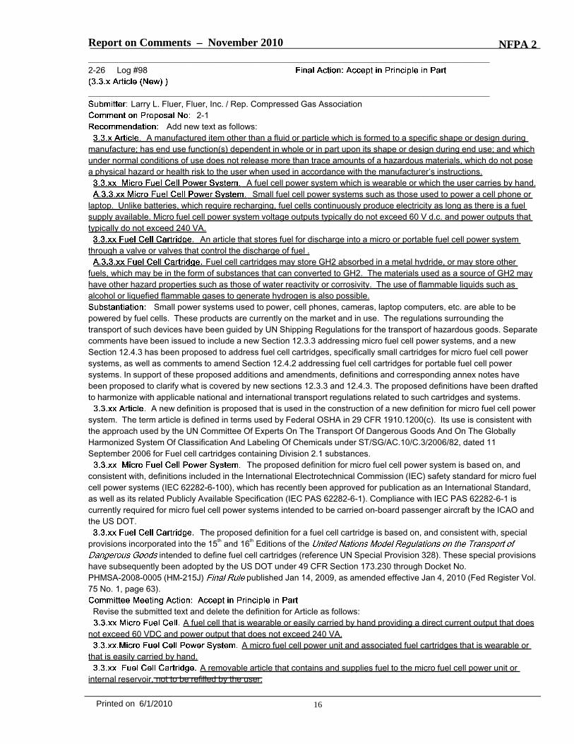
2-1Add new text as follows:
A manufactured item other than a fluid or particle which is formed to a specific shape or design duringmanufacture; has end use function(s) dependent in whole or in part upon its shape or design during end use; and whichunder normal conditions of use does not release more than trace amounts of a hazardous materials, which do not posea physical hazard or health risk to the user when used in accordance with the manufacturer’s instructions.
A fuel cell power system which is wearable or which the user carries by hand.Small fuel cell power systems such as those used to power a cell phone or
laptop. Unlike batteries, which require recharging, fuel cells continuously produce electricity as long as there is a fuelsupply available. Micro fuel cell power system voltage outputs typically do not exceed 60 V d.c. and power outputs thattypically do not exceed 240 VA.
An article that stores fuel for discharge into a micro or portable fuel cell power systemthrough a valve or valves that control the discharge of fuel .
Fuel cell cartridges may store GH2 absorbed in a metal hydride, or may store otherfuels, which may be in the form of substances that can converted to GH2. The materials used as a source of GH2 mayhave other hazard properties such as those of water reactivity or corrosivity. The use of flammable liquids such asalcohol or liquefied flammable gases to generate hydrogen is also possible.
Small power systems used to power, cell phones, cameras, laptop computers, etc. are able to bepowered by fuel cells. These products are currently on the market and in use. The regulations surrounding thetransport of such devices have been guided by UN Shipping Regulations for the transport of hazardous goods. Separatecomments have been issued to include a new Section 12.3.3 addressing micro fuel cell power systems, and a newSection 12.4.3 has been proposed to address fuel cell cartridges, specifically small cartridges for micro fuel cell powersystems, as well as comments to amend Section 12.4.2 addressing fuel cell cartridges for portable fuel cell powersystems. In support of these proposed additions and amendments, definitions and corresponding annex notes havebeen proposed to clarify what is covered by new sections 12.3.3 and 12.4.3. The proposed definitions have been draftedto harmonize with applicable national and international transport regulations related to such cartridges and systems.
A new definition is proposed that is used in the construction of a new definition for micro fuel cell powersystem. The term article is defined in terms used by Federal OSHA in 29 CFR 1910.1200(c). Its use is consistent withthe approach used by the UN Committee Of Experts On The Transport Of Dangerous Goods And On The GloballyHarmonized System Of Classification And Labeling Of Chemicals under ST/SG/AC.10/C.3/2006/82, dated 11September 2006 for Fuel cell cartridges containing Division 2.1 substances.
The proposed definition for micro fuel cell power system is based on, andconsistent with, definitions included in the International Electrotechnical Commission (IEC) safety standard for micro fuelcell power systems (IEC 62282-6-100), which has recently been approved for publication as an International Standard,as well as its related Publicly Available Specification (IEC PAS 62282-6-1). Compliance with IEC PAS 62282-6-1 iscurrently required for micro fuel cell power systems intended to be carried on-board passenger aircraft by the ICAO andthe US DOT.
The proposed definition for a fuel cell cartridge is based on, and consistent with, specialprovisions incorporated into the 15th and 16th Editions of the
intended to define fuel cell cartridges (reference UN Special Provision 328). These special provisionshave subsequently been adopted by the US DOT under 49 CFR Section 173.230 through Docket No.PHMSA-2008-0005 (HM-215J) published Jan 14, 2009, as amended effective Jan 4, 2010 (Fed Register Vol.75 No. 1, page 63).
Revise the submitted text and delete the definition for Article as follows:A fuel cell that is wearable or easily carried by hand providing a direct current output that does
not exceed 60 VDC and power output that does not exceed 240 VA.A micro fuel cell power unit and associated fuel cartridges that is wearable or
that is easily carried by hand.A removable article that contains and supplies fuel to the micro fuel cell power unit or
internal reservoir, not to be refilled by the user.
16Printed on 6/1/2010
Report on Comments – November 2010 NFPA 2
The definitions that are retained from the comment are extracts from IEC TS 62282-100 as thatis the current International Definition as published in the IEC Standard. The definition for Fuel Cell Cartridge wasrevised to remove the requirement for refilling. Refilling is addressed under 2-280 (Log #211). The definition for Articlethat was proposed was not accepted as it is specific to transport and NFPA 2 does not regulate transport operations.Although the term Article is used in the definition of fuel cell cartridge a specific definition over and above that of thedictionary is not needed.
17Printed on 6/1/2010
Report on Comments – November 2010 NFPA 2_______________________________________________________________________________________________2-27 Log #163
_______________________________________________________________________________________________Glenn Mahnken, FM Global
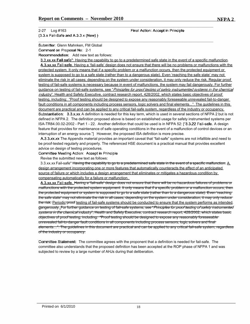
2-1Add new text as follows:
Having the capability to go to a predetermined safe state in the event of a specific malfunction.Having a ‘fail-safe’ design does not ensure that there will be no problems or malfunctions with the
protected system. It only means that if a specific problem or a malfunction occurs, then the protected equipment orsystem is supposed to go to a safe state (rather than to a dangerous state). Even ‘reaching the safe state’ may noteliminate the risk in all cases; depending on the system under consideration, it may only reduce the risk. Regular prooftesting of fail-safe systems is necessary because in event of malfunctions, the system may fail dangerously. For furtherguidance on testing of fail-safe systems, see “
”, Health and Safety Executive, contract research report, 428/2002, which states basic objectives of prooftesting, including: “Proof testing should be designed to expose any reasonably foreseeable unrevealed fail-to-dangerfault conditions in all components including process sensors, logic solvers and final elements...”. The guidelines in thisdocument are practical and can be applied to any critical fail-safe system, regardless of the industry or occupancy.
A definition is needed for this key term, which is used in several sections of NFPA 2 but is notdefined in NFPA 2. The definition proposed above is based on established usage for safety instrumented systems perISA-TR84.00.02-2002 - Part 1 - 22. Another definition that could be used is in NFPA 52: [“ A designfeature that provides for maintenance of safe operating conditions in the event of a malfunction of control devices or aninterruption of an energy source.”] However, the proposed ISA definition is more precise.
The Appendix material provides an important caveat that “fail-safe” systems are not infallible and need tobe proof-tested regularly and properly. The referenced HSE document is a practical manual that provides excellentadvice on design of testing procedures.
Revise the submitted new text as follows:3.3.xx.xx Fail-safe* Having the capability to go to a predetermined safe state in the event of a specific malfunction. A
design arrangement incorporating one or more features that automatically counteracts the effect of an anticipatedsource of failure or which includes a design arrangement that eliminates or mitigates a hazardous condition bycompensating automatically for a failure or malfunction.
Having a ‘fail-safe’ design does not ensure that there will be no hazardous failures of problems ormalfunctions with the protected system equipment. It only means that if a specific problem or a malfunction occurs, thenthe protected equipment or system is supposed to go to a safe state (rather than to a dangerous state). Even ‘reachingthe safe state’ may not eliminate the risk in all cases; depending on the system under consideration, it may only reducethe risk. Periodic proof testing of fail-safe systems should be conducted to ensure that the system performs as intended.dangerously. For further guidance on testing of fail-safe systems, see “
”, Health and Safety Executive, contract research report, 428/2002, which states basicobjectives of proof testing, including: “Proof testing should be designed to expose any reasonably foreseeableunrevealed fail-to-danger fault conditions in all components including process sensors, logic solvers and finalelements…”. The guidelines in this document are practical and can be applied to any critical fail-safe system, regardlessof the industry or occupancy.
The committee agrees with the proponent that a definition is needed for fail-safe. Thecommittee also understands that the proposed definition has been accepted at the ROP phase of NFPA 1 and wassubjected to review by a large number of AHJs during that deliberation.
18Printed on 6/1/2010

Report on Comments – November 2010 NFPA 2_______________________________________________________________________________________________2-28 Log #47
_______________________________________________________________________________________________James R. Rocco, Sage Risk Solutions, LLC
2-1Add a definition for Repair Garages: Buildings and structures used for service and
repair operations in connection with self-propelled CNG-fueled vehicles, LNG-fueled vehicles, or LP-GAS-fueledvehicles, and gaseous and liquid hydrogen fueled vehicles (including, but not limited to, passenger automobiles, buses,trucks and tractors) [30A: 19.4].
Add a definition for Major Repair Garages: A building or portion of a building where majorrepairs, such as engine overhauls, painting, body and fender work, and repairs that require draining of the motor vehiclefuel tank are performed on motor vehicles, including associated floor space used for offices, parking, or showrooms[30A: 3.3.12.10].
The terms "Repair Garages" and Major Repair Garages" are used in a number of places in thedocument. While there are two different terms used, it is not clear what the difference is between these terms in thedocument. The proposed definitions are taken from language in paragraphs 19.1 for repair garages and 3.3.12.1 formajor repair garages. References to major repair garages are typically extracted from NFPA 30A. This will make the useof the term major repair garage consistent with NFPA 30A.
Revise the suggested definition for Repair Garages with:Buildings and structures used for service and repair operations in connection with self-propelled
CNG-fueled vehicles, LNG-fueled vehicles, or LP-GAS-fueled vehicles, and gaseous and liquid hydrogenGH2 and LH2fueled vehicles (including, but not limited to, passenger automobiles, buses, trucks and tractors) [30A: 19.4].
Add a definition for Major Repair Garages:A building or portion of a building where major repairs, such as engine overhauls, painting, body
and fender work, and repairs that require draining venting of the motor vehicle fuel tank are performed on motorvehicles, including associated floor space used for offices, parking, or showrooms [30A: 3.3.12.10].
The committee revised the definition of Repair Garage to be directly applicable to hydrogen.The definition of Major Repair Garage was changed to apply to hydrogen fueled vehicles and the extract tag wascorrected. The extract tag was removed from the definition for Repair Garage because it is not an actual definition inNFPA 30A.
19Printed on 6/1/2010

Report on Comments – November 2010 NFPA 2_______________________________________________________________________________________________2-29 Log #74
_______________________________________________________________________________________________Larry L. Fluer, Fluer, Inc. / Rep. Compressed Gas Association
2-1Revise the presentation of units of measure throughout Section 3.3, whether extracted or not, to
conform to the requirements of order established by Section 1.6.1. The units of measure in the following sections needto be reordered to follow Section 1.6.1:
3.3.30 Capacity3.3.65 Cryogenic Fluid3.3.67 Cylinder3.3.116.4 Flammable Gas3.3.116.5 Flammable Liquefied Gas3.3.116.13 Pyrophoric Gas3.3.116.14 Toxic Gas3.3.116.14.1 Highly Toxic Gas3.3.157 LH2 (also need to add SI units of measure for Critical pressure of 1312.97 kPa.)
Consistency with Section 1.6.1 is needed throughout the document. If for some reason the extractedtext has SI units preceding the inch-pound units of measure, the order can be reversed as an editorial function.
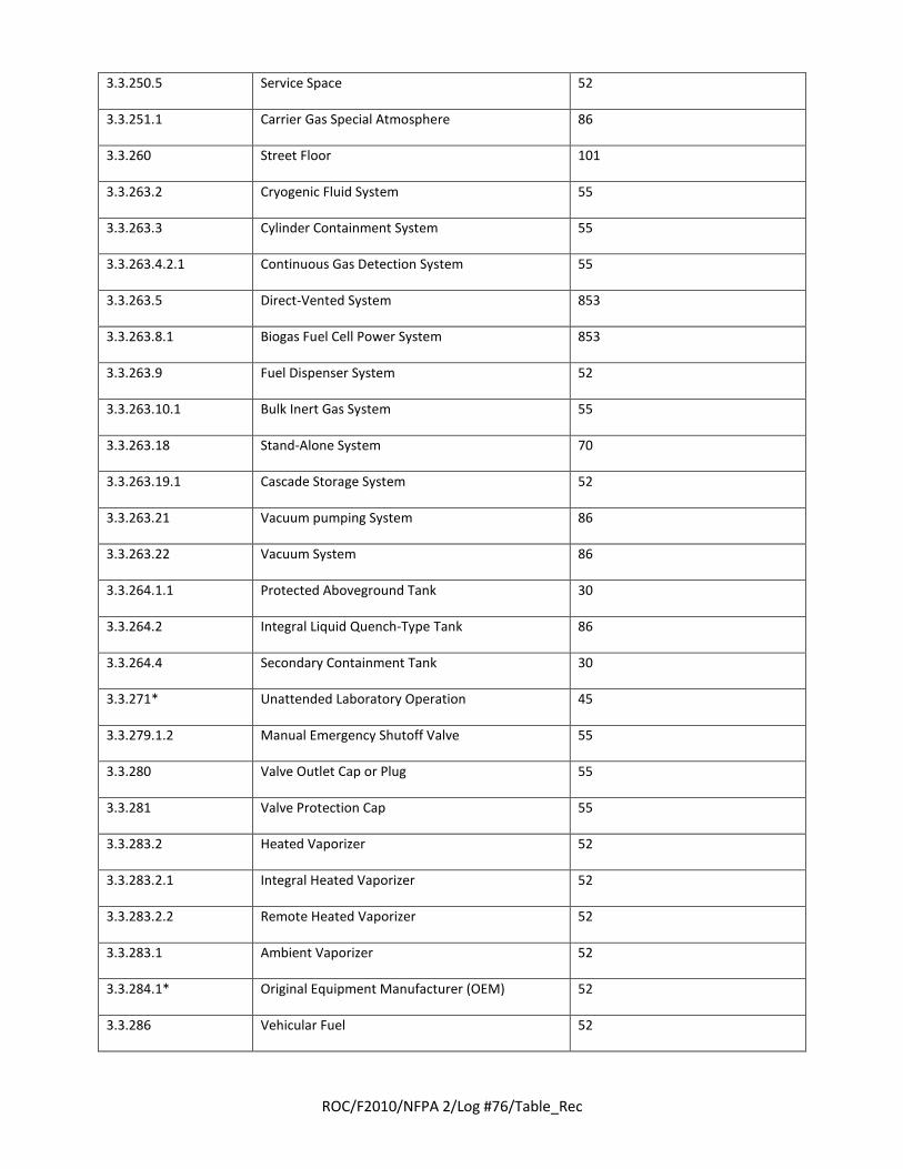
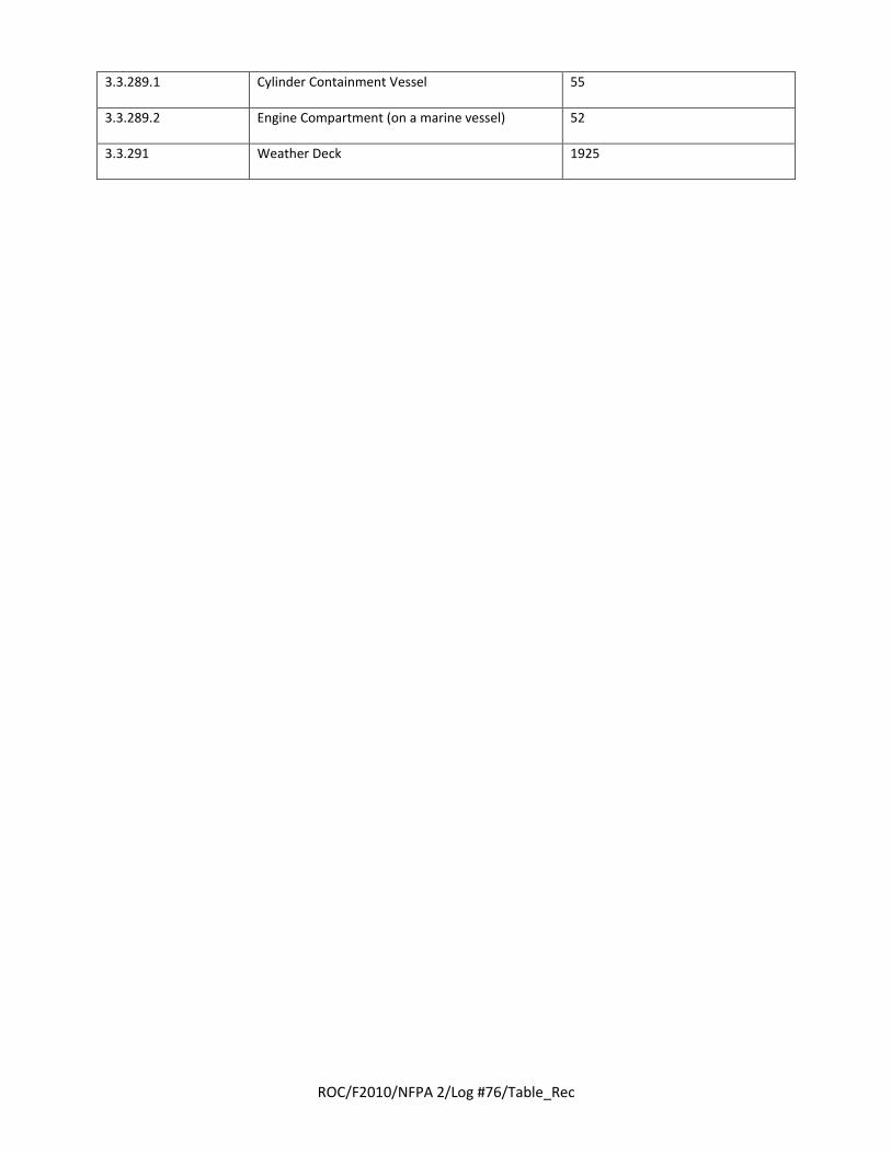
_______________________________________________________________________________________________2-30 Log #76
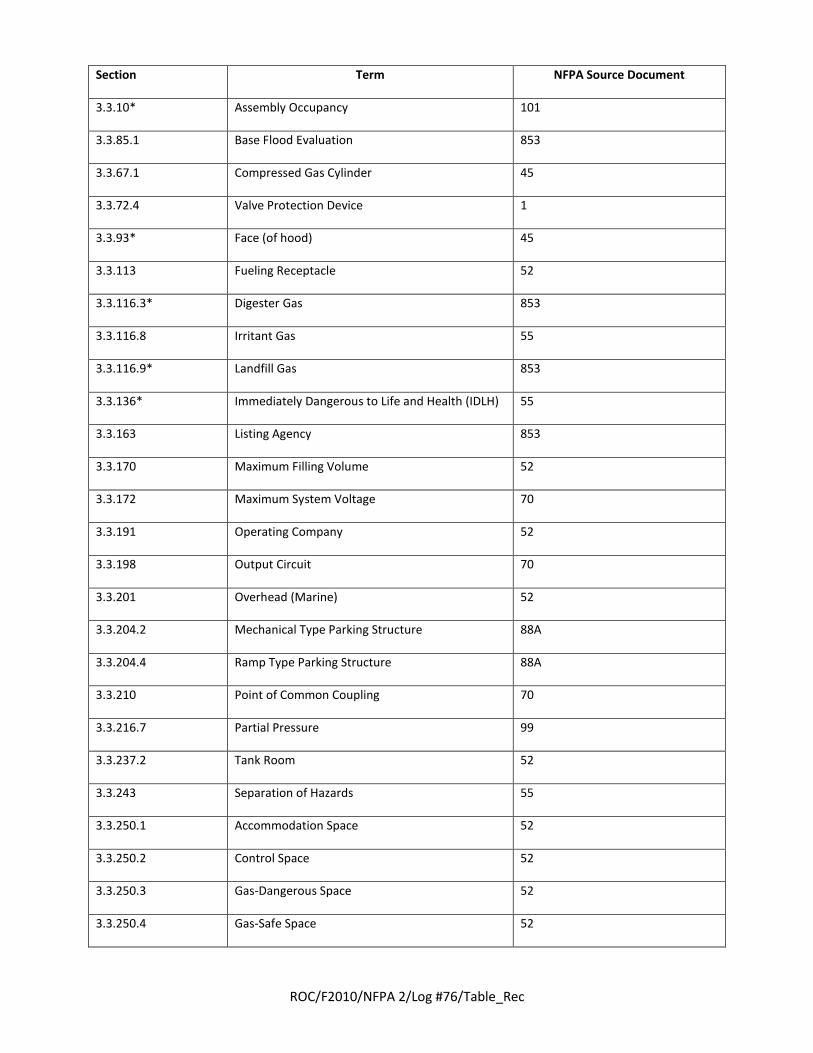
_______________________________________________________________________________________________Larry L. Fluer, Fluer, Inc. / Rep. Compressed Gas Association
2-1Delete the following definitions from Section 3.3. Also delete the cross references to these
definitions and the annex material when annex material is provided:
******Insert 2_L76_Tb_R******
The above definitions are not used in either the body of the document or the annexes.The term “ambient vaporizer” is used in Chapter 15. A new definition for 3.3.283 Vaporizer has been proposed through
a separate public comment along with the addition of an annex note to address the use of the term ambient (typicallyambient air) as a means to provide heat for use in the vaporization process. Deleting the term as such will resolve otherproblems with the definition that incorporate otherwise unused terms such as “remote heated vaporizer.”
20Printed on 6/1/2010
ROC/F2010/NFPA 2/Log #76/Table_Rec
Section Term NFPA Source Document
3.3.10* Assembly Occupancy 101
3.3.85.1 Base Flood Evaluation 853
3.3.67.1 Compressed Gas Cylinder 45
3.3.72.4 Valve Protection Device 1
3.3.93* Face (of hood) 45
3.3.113 Fueling Receptacle 52
3.3.116.3* Digester Gas 853
3.3.116.8 Irritant Gas 55
3.3.116.9* Landfill Gas 853
3.3.136* Immediately Dangerous to Life and Health (IDLH) 55
3.3.163 Listing Agency 853
3.3.170 Maximum Filling Volume 52
3.3.172 Maximum System Voltage 70
3.3.191 Operating Company 52
3.3.198 Output Circuit 70
3.3.201 Overhead (Marine) 52
3.3.204.2 Mechanical Type Parking Structure 88A
3.3.204.4 Ramp Type Parking Structure 88A
3.3.210 Point of Common Coupling 70
3.3.216.7 Partial Pressure 99
3.3.237.2 Tank Room 52
3.3.243 Separation of Hazards 55
3.3.250.1 Accommodation Space 52
3.3.250.2 Control Space 52
3.3.250.3 Gas-Dangerous Space 52
3.3.250.4 Gas-Safe Space 52
ROC/F2010/NFPA 2/Log #76/Table_Rec
3.3.250.5 Service Space 52
3.3.251.1 Carrier Gas Special Atmosphere 86
3.3.260 Street Floor 101
3.3.263.2 Cryogenic Fluid System 55
3.3.263.3 Cylinder Containment System 55
3.3.263.4.2.1 Continuous Gas Detection System 55
3.3.263.5 Direct-Vented System 853
3.3.263.8.1 Biogas Fuel Cell Power System 853
3.3.263.9 Fuel Dispenser System 52
3.3.263.10.1 Bulk Inert Gas System 55
3.3.263.18 Stand-Alone System 70
3.3.263.19.1 Cascade Storage System 52
3.3.263.21 Vacuum pumping System 86
3.3.263.22 Vacuum System 86
3.3.264.1.1 Protected Aboveground Tank 30
3.3.264.2 Integral Liquid Quench-Type Tank 86
3.3.264.4 Secondary Containment Tank 30
3.3.271* Unattended Laboratory Operation 45
3.3.279.1.2 Manual Emergency Shutoff Valve 55
3.3.280 Valve Outlet Cap or Plug 55
3.3.281 Valve Protection Cap 55
3.3.283.2 Heated Vaporizer 52
3.3.283.2.1 Integral Heated Vaporizer 52
3.3.283.2.2 Remote Heated Vaporizer 52
3.3.283.1 Ambient Vaporizer 52
3.3.284.1* Original Equipment Manufacturer (OEM) 52
3.3.286 Vehicular Fuel 52
ROC/F2010/NFPA 2/Log #76/Table_Rec
3.3.289.1 Cylinder Containment Vessel 55
3.3.289.2 Engine Compartment (on a marine vessel) 52
3.3.291 Weather Deck 1925

Report on Comments – November 2010 NFPA 2_______________________________________________________________________________________________2-31 Log #86
_______________________________________________________________________________________________Larry L. Fluer, Fluer, Inc. / Rep. Compressed Gas Association
2-1Revise text as follows:
Air removed from a space or power system and not reused. [ , 2007]The portion of supply air whose source is the outside/outdoors plus
any recirculated air that has been treated and is acceptable for use by the power system ventilation system. [ , 2007]The term exhaust air has been extracted from NFPA 853, however, the term is not used in Chapter 12.
The inclusion of power system as a portion of the definition does not appear to add a necessary component to thedefinition. An extract from NFPA 853 is not necessary in the form is used in Chapters 8, 16 and elsewhere in thegeneric sense. If the term is to be retained without revision it should be limited to fuel cell power systems. The alternatewould be to strike the phrase “or power system” and strike the reference tag to NFPA 853 and retain the term in Chapter3.
The term ventilation air is used in Chapters 12, 13 and 19, but it is not always tied to power system ventilation. Thereare six separate definitions for the term “ventilation” in the 2004 Glossary of Terms. It is not clear why an additionaldefinition is necessary. That said, the addition of a parenthetical term will limit the existing definition to use with fuel cellpower systems. As used in Chapters 13 and 19 having a definition does not appear to add anything to the code. Theterm “ventilation air” is not used within the context of NFPA 90A and 90B or NFPA 91 all of which deal with ventilation inone form or another. The definition is parallel to that used by the International Mechanical Code except with minormodification and the insertion of the term power system (fuel cell power system implied).
The alternative is to place use specific definitions into the use specific chapter where the definition is intended to apply.
Revise the proposed text as follows:Air removed from a space or power system and not reused. [ , 2007]
The portion of supply air whose source is the outside/outdoors plusany recirculated air that has been treated and is acceptable for use by the power system ventilation system. [ , 2007]
The deleted text was viewed as superfluous to the inserted parenthetical text.
21Printed on 6/1/2010
Report on Comments – November 2010 NFPA 2_______________________________________________________________________________________________2-32 Log #69
_______________________________________________________________________________________________Larry L. Fluer, Fluer, Inc. / Rep. Compressed Gas Association
2-1Revise text as follows:
A room or space [regulated by Chapter 16 used] for testing, analysis, research,instruction, or similar activities that involve the use of chemicals. [ 2004]
Any space within a [laboratory] building not included in a laboratory unit.[ 2004]
A structure consisting wholly or principally of one or more laboratory units.[ 2004]
A laboratory is a facility regulated by Chapter 16 that provides controlled conditions in whichscientific research, experiments, or measurements are performed.
An enclosed space [within a laboratory building] used for experiments or tests. Alaboratory unit can include offices, lavatories, and other incidental contiguous rooms maintained for or used bylaboratory personnel, and corridors within the unit. It can contain one or more separate laboratory work areas. It can bean entire building. [A laboratory unit is classified as A, B, C, or D in accordance with Section 4.2. ( )][ 2004]
A laboratory unit is classified as A, B, C, or D in accordance with NFPA 45, 2004 edition.
Also add the following document to Annex K under K.1.1NFPA 45 , 2004 edition.
As currently written the extract definition used to define “laboratory work area” implies that everybuilding is classified with relationship to laboratories which is the specific subject of Chapter 16. It is quite common tohave chemicals used for testing in production facilities that are in fact exempt from the requirements of Chapter 16. Theexemptions in Section 16.1.2 are not evident to users which may never refer to Chapter 16. The proposed change toSection 3.3.8.3 will avoid having areas using chemicals where testing, or similar activities occur, classified as laboratorywork areas.
To classify a space as a non-laboratory area one must be in a “laboratory building” as defined by 3.3.18.2. Theproposed change clarifies the fact that the universe of buildings regulated by Chapter 16 is confined to those which arethe focus of Chapter 16. Without the change the code user is forced to go to Chapter 16 to search for requirements thatmay never apply. The proposed change clarifies the fact that the subject of the definition is companion to Chapter 16.The added reference to 3.3.18.2 is user friendly and refers the user to the term “laboratory building” as well as“laboratory unit.”
The addition of the reference note to 3.3.18.24 refers the user to the definition of laboratory unit which is used withinthe context of 3.3.18.4.
The proposed change to 3.3.149 is intended to clarify that the term laboratory is limited to only those areas soclassified that are regulated by Chapter 16.
The change to 3.3.272.1 is to establish that the term laboratory unit only applies to “enclosed areas” within laboratorybuildings, and to move an informational note from the definition to the Annex. Without the addition of the term“laboratory building” it is implied that any enclosed space used for experiments or tests is in fact a laboratory unit.Informational notes and/or requirements should not be included in a definition.
Revise the submitted text as follows:A room or space [regulated by Chapter 16 used] for testing, analysis, research,
instruction, or similar activities that involve the use of chemicals. [ 2004]Any space within a [laboratory] building not included in a laboratory unit.
[ 2004]A structure consisting wholly or principally of one or more laboratory units.
[ 2004]A laboratory is a facility regulated by Chapter 16 that provides controlled conditions in which
scientific research, experiments, or measurements are performed.An enclosed space [within a laboratory building] used for experiments or tests. A
laboratory unit can include offices, lavatories, and other incidental contiguous rooms maintained for or used by
22Printed on 6/1/2010
Report on Comments – November 2010 NFPA 2laboratory personnel, and corridors within the unit. It can contain one or more separate laboratory work areas. It can bean entire building. [A laboratory unit is classified as A, B, C, or D in accordance with Section 4.2. ( )][ 2004]
A laboratory unit is classified as A, B, C, or D in accordance with NFPA 45, 2004 edition.
Also add the following document to Annex K under K.1.1NFPA 45 , 2004 edition.
Deleted reference to Annex D of NFPA 45 and added a star to 3.3.272.1.
_______________________________________________________________________________________________2-33 Log #68
_______________________________________________________________________________________________Larry L. Fluer, Fluer, Inc. / Rep. Compressed Gas Association
2-1Revise text as follows:
(laboratory hoods). An airflow-compensating opening that maintains a relatively constant volumeexhaust through a chemical fume hood regardless of sash position, serving to limit the maximum face velocity as thesash is lowered. [45, 2004]
The use of the term bypass appears in various portions of the code other than Chapter 16. A methodneeds to be developed to confine use specific definitions to the chapter in which they were intended or perhaps by ameans that conveys the intent of where they are to be used. It is proposed to confine this definition to laboratory hoodsas used in Chapter 16. An alternate to consider would be to use a parenthetical (Chapter 16) following the definition orto develop an approach such that chapter specific definitions are confined to the use specific chapters. The abovechange is the simplest change in that the format of use specific chapters remains unchanged.
_______________________________________________________________________________________________2-34 Log #80
_______________________________________________________________________________________________Larry L. Fluer, Fluer, Inc. / Rep. Compressed Gas Association
2-1Revise text as follows:
The water volume of a container in liters (gallons). [ 2010]The term capacity is used throughout the document. As used in NFPA 52 the term is limited to the
determination of the capacity of a vehicle fuel container. The use of a parenthetical term following the definition is anoption. Another option would be to create a section for definitions in each use specific chapter in which their use islimited to the chapter.
23Printed on 6/1/2010

Report on Comments – November 2010 NFPA 2_______________________________________________________________________________________________2-35 Log #81
_______________________________________________________________________________________________Larry L. Fluer, Fluer, Inc. / Rep. Compressed Gas Association
2-1Delete text as follows:
The amount of water at 60°F (16°C) required to fill a container. [ , 2010]The term water capacity is used throughout the code. The basis for using a temperature of 60
degrees F is unknown, and the 60 degree temperature is out of the norm. If the intent is to use water at linetemperature from the public supply is intended it is not clear. The specific volume of water is essentially constant over awide range of temperatures. At 32 degrees F it is 0.01602 cubic feet/pound and at 212 degrees it is 0.01672.Capacities of containers as used in the code are typically established using water from the public supply. Standardizingcapacity on a temperature of 60 degrees F is not the norm and outside of the current practice. The term has not beenused in any of the fueling specific requirements found within NFPA 2.
_______________________________________________________________________________________________2-36 Log #52
_______________________________________________________________________________________________Bob Eugene, Underwriters Laboratories Inc.
2-1Revise text as follows:
. Limited-Combustible Material. Refers to a building construction material not complyingwith the definition of noncombustible that, in the form in which it is used, has a potential heat value not exceeding 8141kJ/kg (3500 Btu/lb), where tested in accordance with NFPA 259,
, and includes either (1) materials having a structural base of noncombustible material, with a surfacing notexceeding a thickness of 3.2 mm (in.) that has a flame spread index not greater than 50, or (2) materials, in the form andthickness used having neither a flame spread index greater than 25 nor evidence of continued progressive combustion,and of such composition that surfaces that would be exposed by cutting through the material on any plane would haveneither a flame spread index greater than 25 nor evidence of continued progressive combustion, when tested inaccordance with ANSI/UL 723 or ASTM E 84. [ , 2009]
Editorial. Adds ANSI approval designation to ANSI/UL 723.
24Printed on 6/1/2010
Report on Comments – November 2010 NFPA 2_______________________________________________________________________________________________2-37 Log #70
_______________________________________________________________________________________________Larry L. Fluer, Fluer, Inc. / Rep. Compressed Gas Association
2-1Revise text as follows:
. A pressure vessel designed for absolute pressures higher than 276 kPa (40 psi) 40 psi (276 kPa) andhaving a circular cross-section. It does not include a portable tank, multiunit tank car tank, cargo tank, or tank car. [2010]
Any portable pressure vessel of 45.4 kg (100 lb) water capacity or less designedto contain a gas or liquid that is authorized for use at gauge pressures over 276 kPa (40 psi) at 21°C (70°F) by the U.S.Department of Transportation (DOT) or Transport Canada (T.C.). [ 2004]
See 3.3.67.1.Section 1.6.1 requires that U.S. customary units of measure be presented first to be followed by SI
units. Changing the order of presentation for the units of measure as shown in 3.3.67 is an editorial function.The definition of compressed gas container extracted from NFPA 45 is technically incorrect and in conflict with US
DOT regulations as well as with the term “cylinder” as defined by 3.3.67. As defined by NFPA 45 cylinders for gaseswith a vapor pressure less than 40 psig or which are compressed to pressures less than 40 psig would not be classifiedas compressed gas cylinders. Calibration gases or hydrogen in low pressure cylinders could be packaged at pressuresof less than 40 psig.
There is no valid reason to publish a definition that is in conflict with federal regulations or to create confusion withinNFPA 2. The term is used twice in Chapter 16 (Sections 16.2.1.1(3) and 16.3.1.2.3). Deleting the term does notadversely affect the intent of either section. The cross reference in 3.3.51 should be deleted in its entirety.
_______________________________________________________________________________________________2-38 Log #75
_______________________________________________________________________________________________Larry L. Fluer, Fluer, Inc. / Rep. Compressed Gas Association
2-1Revise text as follows:
A mobile unit designed to transport LNG, CNG, GH2, or LH2. [2010]
The term “cargo transport container” is not used within the document. The term “cargo transportvehicle” is used in Sections 8.3.4.5.2, 8.3.4.5.6 and 11.2.16.2. The title of the term should be correlated with the use ofthe term or the definition should be deleted.
Revise the submitted text as follows:A mobile unit designed to transport LNG, CNG, GH2, or LH2. [
2010]Deleted LNG and CNG to be consistent with the scope of NFPA 2.
25Printed on 6/1/2010
Report on Comments – November 2010 NFPA 2_______________________________________________________________________________________________2-39 Log #79
_______________________________________________________________________________________________Larry L. Fluer, Fluer, Inc. / Rep. Compressed Gas Association
2-1Revise text as follows:
A device designed to cut off the source of heat if the operatingtemperature exceeds a predetermined temperature set point. [ 2007]
Add the term “limit” in Section 15.3.1.1.10.13 to correlate with the use of the term as follows:The temperature indication of the excess temperature [limit] controller shall be verified to be accurate
[ 7.5.13]The term “Excess Temperature Limit Controller” does not appear in the document other than in
3.3.60.1 and the related cross reference. The term as used in Section 15.3.1.1.10.13 is “Excess TemperatureController.” The defined term should be correlated with the Chapter in which it is used, or the defined term should bedeleted.
_______________________________________________________________________________________________2-40 Log #82
_______________________________________________________________________________________________Larry L. Fluer, Fluer, Inc. / Rep. Compressed Gas Association
2-1Revise text as follows:
A device that closes all operations within the fuelingfacility from either local or remote locations. [ 2010]
The term emergency shutdown device is specific to vehicular fueling. Its use is confined to Chapters10 and 11, however, the terminology suggests a broader use which may be inappropriate. Other terms including“emergency shutdown system” are used in other chapters of the code when systems rather than devices are described.There is no definition of emergency shutdown system. The term “closes all operations within the fueling facility” issomewhat vague, and although it may have been the intent to confine “operations” to the fueling function it isquestionable. The use of a parenthetical term following the definition is an option which would confine the definition tothose related to vehicle fueling. Another option would be to create a section for definitions in each use specific chapterin which their use is limited to the chapter.
26Printed on 6/1/2010
Report on Comments – November 2010 NFPA 2_______________________________________________________________________________________________2-41 Log #165
_______________________________________________________________________________________________Glenn Mahnken, FM Global
2-1Revise text a follows:
A device that is a component of an emergency shutdown system andthat when activated closes all operations within the facility from either local or remote locations.
A control system composed of any combination of sensor(s), logicsolver(s) and final element(s) dedicated to manually and/or automatically shutting down a process in a safe controlledmanner in event of defined abnormal conditions.
Emergency Shutdown System (ESD) is also commonly abbreviated as “ESS”. Other equivalent terms areSafety Shutdown System (SSD), and Safety Interlock System. The term Safety Instrumented System (SIS) typicallyrefers to a type of ESD that meets formal requirements for safety and reliability according to ISA (Instrument Society ofAmerica) publication ANSI/ISA S84.01 or IEC(International Electrotechnical Committee) Publication 61508-
All ESDs devices shall be of a type requiring that they be manuallyreset. [52:14.11.2.1]
The abbreviation “ESD” is used with two different meanings in NFPA 2. One is EmergencyShutdown System (for example in 8.3.1.2.9) which was extracted from NFPA 55; the other is Emergency ShutdownDevice, (11.2.15.1) which was extracted from NFPA 52. Since the NFPA 55 usage of ESD is broader, it should beadopted in NFPA 2 and a corresponding definition should be added.
Since ESD is not defined in NFPA 55, above is an attempt at a definition corresponding to common usageand ISA-TR84.00.02-2002 - Part 1 - 22.
The Appendix statement clarifies the other equivalent terms for ESD and other abbreviations inwidespread use.
The statement was changed to be consistent with the revised definition of “ESD”.
This was rejected at the request of the proponent. The proposed definition for EmergencyShutdown System was inconsistent with the application of the term in NFPA 2.
_______________________________________________________________________________________________2-42 Log #83
_______________________________________________________________________________________________Larry L. Fluer, Fluer, Inc. / Rep. Compressed Gas Association
2-1Revise text as follows:
An instrument, a control, or other equipment that acts, or initiates action, tocause the furnace to revert to a safe condition in the event of equipment failure or other hazardous event. [ 2007]
The term “safety device” appears throughout the code. In some cases the term is a carryover from anow obsolete term for what are now called “pressure relief devices” as found on compressed gas cylinders. Forexample, the reference in 19.4.3.1 from NFPA 30A refers to safety devices that are other than those contained onfurnace control systems. The reference as used in 7.3.2.4.4.2 refers to what are now known as pressure relief deviceswithin the context of NFPA 55. The use of a parenthetical term can serve to limit the application of the definition.Alternatively, use specific chapter definitions can be confined to the chapter in which they are used.
27Printed on 6/1/2010
Report on Comments – November 2010 NFPA 2_______________________________________________________________________________________________2-43 Log #71
_______________________________________________________________________________________________Larry L. Fluer, Fluer, Inc. / Rep. Compressed Gas Association
2-1Delete text as follows:
A device attached to the neck ring or body of a cylinder for the purpose ofprotecting the cylinder valve from being struck or from being damaged by the impact resulting from a fall or an objectstriking the cylinder. [ 2009]
See 3.3.72.4.The term “valve protection device” is not used within the document. NFPA 55 uses the additional term
“valve protection cap,” but neither term is used within NFPA 2.
_______________________________________________________________________________________________2-44 Log #43
_______________________________________________________________________________________________James R. Rocco, Sage Risk Solutions, LLC
2-1Add the definitions for Attended Self-Service Motor Fuel Dispensing Facility, Full-Service Motor
Fuel Dispensing Facility, and Unattended Self-Service Motor Fuel Facility from NFPA 30A, 2008 paragraphs 3.3.11.1,3.3.11.3, and 3.3.11.6, respectively to this paragraph.
These are common terms used within the industry and defined in NFPA 30A. The proposed documentincludes discussions of full service, attended self-service, and unattended self service in most cases extracted fromNFPA 30A paragraphs 11.3.3.3, 11.3.3.4 and 11.3.3.5. For consistency between these standards, the terminologyshould be consistent and these definitions should be included. Changes to the titles of paragraphs 11.3.3.3, 11.3.3.4,and 11.3.3.5, to be consistent with these definitions, are proposed in a separate comment.
_______________________________________________________________________________________________2-45 Log #54
_______________________________________________________________________________________________Bob Eugene, Underwriters Laboratories Inc.
2-1Revise text as follows:
. Limited-Combustible Material. Refers to a building construction material not complyingwith the definition of noncombustible that, in the form in which it is used, has a potential heat value not exceeding 8141kJ/kg (3500 Btu/lb), where tested in accordance with NFPA 259,
, and includes either (1) materials having a structural base of noncombustible material, with a surfacing notexceeding a thickness of 3.2 mm (0.126 in.) that has a flame spread index not greater than 50, or (2) materials, in theform and thickness used having neither a flame spread index greater than 25 nor evidence of continued progressivecombustion, and of such composition that surfaces that would be exposed by cutting through the material on any planewould have neither a flame spread index greater than 25 nor evidence of continued progressive combustion, whentested in accordance with ANSI/UL 723 or ASTM E 84. [ , 2009]
Editorial. Adds ANSI approval designation to ANSI/UL 723.
See 2-36 (Log #52) where ANSI was added to this definition. The comment refers to the wrongdefinition number and should be to 3.3.46.1.
28Printed on 6/1/2010
Report on Comments – November 2010 NFPA 2_______________________________________________________________________________________________2-46 Log #84
_______________________________________________________________________________________________Larry L. Fluer, Fluer, Inc. / Rep. Compressed Gas Association
2-1Revise text as follows:
The location where a Fuel Cell Power System [other than a micro fuelcell power system] is sited as a unit or built as an assembly. [ , 2007]
A Fuel Cell Power System [other than a micro fuel cell powersystem] completely surrounded and enclosed by walls, a roof, and a floor. [ , 2007]
A power system installation [other than a microfuel cell power system] that is not located inside a building or that has only partial weather protection (maximumcoverage of a roof and up to 50 25 percent enclosing walls). [ ,2007]
. A Fuel Cell [Power System] generator [other than a microfuel cell power system] of electricity that is not fixed in place. A portable appliance utilizes a cord and plug connection toa grid-isolated load and has an integral fuel supply. [ , 2007]
The term “installation” is used throughout the code. The user first encounters the term in Section 1.2which is the “purpose” section of the code. The use of a parenthetical phrase will limit the use of the term as defined tofuel cell power systems. Alternatively, such definitions can be confined to the chapter in which they are used byrelocating the definitions specific to the chapter to a section of the code dedicated to use specific definitions. A similarproblem is presented by the use of the term in 3.3.141.1, 3.3.141.2 and 3.3.141.4 and a parenthetical term is warranted.
The following reasons are submitted for each of the sections for which a comment has been proposed:3.3.141, 3.3.141.1, 3.3.141.2 and 3.3.141.3: The term “installation” is a general term that applies to equipment
throughout the document. Extracting a definition from NFPA 853 pertinent only to fuel cell power systems withoutqualification creates confusion for the code user. The addition of a parenthetical term following the extract definitionpartially resolves the problem. The same resolution has been proposed for the sub-definitions found in this section aswell. The addition of the parenthetical phrase is viewed as editorial.
Micro fuel cell power systems may be used in the form of a cartridge to power a cell phone or small portable device.These systems are not “installed” within the context of the term. Micro fuel cell power systems should not beincorporated into the definition for fuel cell power systems thereby imposing requirements not otherwise intended. Eachof the definitions has been revised to allow for the development of specific definitions for micro fuel cell power systems.
3.3.141.2. The description of “weather protection” as a concept as embodied in 3.3.141.2 is in conflict with NFPA 1,5000, the IBC, IFC and other model codes. To be considered outdoors no more than 25 percent of the perimeter of aweather protection structure (other than the roof) can be closed. In other words 75% of the walled perimeter surfacearea must be open to the atmosphere. The change from 50 to 25% will coordinate NFPA 2 with the model building andfire prevention codes in keeping with the Standards Council directive. If a figure of 50% remains a conflict is presentedin which case the model building or fire prevention codes would override the requirements of NFPA 853. By notresolving the problem here it is likely to confuse code users and it presents a problem for the AHJ that can be resolvedby accepting the change.
Revise the submitted text as follows:The location where a Fuel Cell Power System [other than a portable or
micro fuel cell power system] is sited as a unit or built as an assembly. [ , 2007]A Fuel Cell Power System [other than a portable or micro fuel
cell power system] completely surrounded and enclosed by walls, a roof, and a floor. [ , 2007]A power system installation [other than a portable
or micro fuel cell power system] that is not located inside a building or that has only partial weather protection(maximum coverage of a roof and up to 50 25 percent enclosing walls). [ ,2007]
. A Fuel Cell [Power System] generator [other than a microfuel cell power system] of electricity that is not fixed in place. A portable appliance utilizes a cord and plug connection toa grid-isolated load and has an integral fuel supply. [ , 2007]
The revised text is consistent with having a separate section on portable and micro fuel cells inChapter 12.
29Printed on 6/1/2010
Report on Comments – November 2010 NFPA 2_______________________________________________________________________________________________2-47 Log #87
_______________________________________________________________________________________________Larry L. Fluer, Fluer, Inc. / Rep. Compressed Gas Association
2-1Revise text as follows:
Hydrogen in the a liquid phase. form normally stored below its critical pressure (190.43 psi). [ , 2010]Hydrogen in a liquid state is a flammable cryogenic fluid, regardless of the pressure.
Hydrogen in the gas phase a gaseous form. [ , 2010]For every pure, chemically stable substance there is a certain temperature and pressure at which it
can exist in all three states or phases, solid, liquid, and vapor each phase being in equilibrium with each of the others.The term “phase” is in keeping with a terminology that is commonly used and understood by those involved in theproduction and use of this material whether as a liquid or a gas. Defining LH2 in terms of its critical pressure does notadd significant value to the definition as can be seen from the annex note.
_______________________________________________________________________________________________2-48 Log #78
_______________________________________________________________________________________________Larry L. Fluer, Fluer, Inc. / Rep. Compressed Gas Association
2-1Delete the definition of hazardous material currently found in 3.3.166.1 and replace it with the
following extract definitions:A substance that, by reason of being explosive, flammable, poisonous,
corrosive, oxidizing, irritating, or otherwise harmful, is likely to cause death or injury. [ , 2007]A chemical or substance that is classified as a physical hazard material or a health
hazard material, whether the chemical or substance is in usable or waste condition.[ 2009]
A chemical or substance classified as a toxic, highly toxic, or corrosive material inaccordance with the definitions set forth in this . [ 2009]
A chemical or substance classified as a combustible liquid, explosive, flammablecryogen, flammable gas, flammable liquid, flammable solid, organic peroxide, oxidizer, oxidizing cryogen, pyrophoric,unstable (reactive), or water-reactive material. [ 2009]
The definition of hazardous material extracted from NFPA 853 is in conflict with NFPA 1 Fire Code,NFPA 5000 Building Construction Safety Code, and NFPA 400 Hazardous Materials Code. The NFPA StandardsCouncil has asked that the technical committees dealing with hazardous commodities coordinate their terminology forhazardous materials including the control area concepts with NFPA1 and 5000. Irritants as embodied in the definitionextracted from NFPA 853 are not considered health hazards within the context of the codes and standards that are to beused as the basis for definition.
Various sections throughout NFPA 2 refer to physical and health hazards without the benefit of a definition.Coordination as directed by the Standards Council policy is warranted and brings consistency to the application of theterm as used by the referenced codes as well as with model codes published by the International Codes Council therebypromoting consistency nationally.
The committee believes that the scope of the material being extracted belongs under NFPA400 and not NFPA 5000 [See committee action on 2-49 (Log #108)].
30Printed on 6/1/2010
Report on Comments – November 2010 NFPA 2_______________________________________________________________________________________________2-49 Log #108
_______________________________________________________________________________________________Larry L. Fluer, Fluer, Inc. / Rep. Compressed Gas Association
2-1Revise text as follows:
A substance that, by reason of being explosive, flammable, poisonous,corrosive, oxidizing, irritating, or otherwise harmful, is likely to cause death or injury. [ , 2007]
A chemical or substance that is classified as a physical hazard material or a healthhazard material, whether the chemical or substance is in usable or waste condition.
[ 2010]Hazardous wastes might or might not be classified as hazardous materials.
Management and disposal of hazardous waste is regulated by the EPA under the Resource Conservation and RecoveryAct (RCRA). EPA requires wastes identified as hazardous to be handled, stored, treated, and disposed of accroding tothe stipulations of the RCRA hazardous waste program in 40 CFR 260 to 265 and 40 CFR 266 to 299.
Not all of the hazardous materials categories are placed into the high hazard category, and some of these materialshave been recognized as being of low or ordinary hazards, depending on their nature in a fire. Inert compressed gasesand inert cryogenic fluids, Class IIIB combustible liquids, Class 1 unstable (reactive) materials, Class 1 water-reactivematerials, Class 1 oxidizing solids and liquids, and Class IV and Class V organic peroxides are high hazard materials,which, in some cases, do not have an established (MAQ) and, therefore,are not required to comply with the requirements for hazardous occupancies within the context of the adopted buildingcodes.
A chemical or substance classified as a toxic, highly toxic, or corrosive material inaccordance with definitions set forth in this . [ 2010]
A chemical or substance classified as a combustible liquid, explosive, flammablecryogen, flammable gas, flammable liquid, flammable solid, organic peroxide, oxidizer, oxidizing cryogen, pyrophoric,unstable (reactive), or water-reactive material. [ 2010]
The terms "poisonous, irritating, or otherwise harmful" brings a wide array of materials into the codethat have not been intended for regulation. Irritants, sensitizers, target organ toxins, radioactive materials are a fewwhich have been excluded for a number of specific reasons. If left unchanged the existing definition would have anegative impact on the use of Tables such as Table 7.3.2.3.1.1(A). It is not uncommon to have nitrogen located inproximity to hydrogen in tank farms located at user sites. There are no separation distances required under the NFPA55 concept established between the category of "other" gas (which includes inert gases) and flammable gases asshown in Table 7.1.10.2.
Revise the submitted text as follows:A substance that, by reason of being explosive, flammable, poisonous,
corrosive, oxidizing, irritating, or otherwise harmful, is likely to cause death or injury. [ , 2007]1 A chemical or substance that is classified as a physical hazard material or a health
hazard material, whether the chemical or substance is in usable or waste condition.[ 2010]
Hazardous wastes might or might not be classified as hazardous materials.Management and disposal of hazardous waste is regulated by the EPA under the Resource Conservation and RecoveryAct (RCRA). EPA requires wastes identified as hazardous to be handled, stored, treated, and disposed of accroding tothe stipulations of the RCRA hazardous waste program in 40 CFR 260 to 265 and 40 CFR 266 to 299.
Not all of the hazardous materials categories are placed into the high hazard category, and some of these materialshave been recognized as being of low or ordinary hazards, depending on their nature in a fire. Inert compressed gasesand inert cryogenic fluids, Class IIIB combustible liquids, Class 1 unstable (reactive) materials, Class 1 water-reactivematerials, Class 1 oxidizing solids and liquids, and Class IV and Class V organic peroxides are high hazard materials,which, in some cases, do not have an established (MAQ) and, therefore,are not required to comply with the requirements for hazardous occupancies within the context of the adopted buildingcodes.
A chemical or substance classified as a toxic, highly toxic, or corrosive material in
31Printed on 6/1/2010

Report on Comments – November 2010 NFPA 2accordance with definitions set forth in this . [ 2010]
A chemical or substance classified as a combustible liquid, explosive, flammablecryogen, flammable gas, flammable liquid, flammable solid, organic peroxide, oxidizer, oxidizing cryogen, pyrophoric,unstable (reactive), or water-reactive material. [ 2010]
The committee added a star to 3.3.161.1 and changed the numbering to read 3.3.166.1 forHazardous Material.
_______________________________________________________________________________________________2-50 Log #88
_______________________________________________________________________________________________Larry L. Fluer, Fluer, Inc. / Rep. Compressed Gas Association
2-1Revise text as follows:
A DOT-approved vehicle with tank(s) and pump(s) that dispenses engine fueldirectly to vehicles. [52, 2010]
The mobile refueler may also contain a compressor for pressurizing the gas to bedispensed and a dispenser which is the equipment which is the interface between the supply vehicle and the vehicle tobe fueled.
The term “refueling” is a verb while the descriptive of a vehicle is a noun. A term refueler is a nounthat is intended to describe the equipment to be used. The extract definition as written appears to limit the vehicle tobeing equipped with pumps which are normally associated with the transfer of liquid rather than compressors which aretypically associated with the transfer of gas at high pressure. The refuelers are equipped with dispensers whichmeasure the fuel being dispensed and provide a control system that interfaces with the vehicle being fueled.
_______________________________________________________________________________________________2-51 Log #89
_______________________________________________________________________________________________Larry L. Fluer, Fluer, Inc. / Rep. Compressed Gas Association
2-1Revise text as follows:
An individual trained and responsible for the start-up, operation, shutdown, andemergency handling of the furnace and associated equipment. [ 2007]
The term “operator” is used throughout the code in terms of persons, such as in Sections 4.2.3.1.2.5,7.3.1.2.8, or equipment such as in Section 7.1.6.2. The addition of a parenthetical term is recommended in order to limitthe proposed definition to use in Chapter 15. The alternative is to provide a definition section in the use specificchapters to locate definitions unique to each chapter.
_______________________________________________________________________________________________2-52 Log #CC18
_______________________________________________________________________________________________Technical Committee on Hydrogen Technology,
2-8Modify 3.3.212 as follows:
See 3.3.138.3 See 3.3.143.3.
Corrected capitalizations and the incorrect reference.
32Printed on 6/1/2010

Report on Comments – November 2010 NFPA 2_______________________________________________________________________________________________2-53 Log #91
_______________________________________________________________________________________________Larry L. Fluer, Fluer, Inc. / Rep. Compressed Gas Association
2-1Revise text as follows:
A temperature of 70°F (21.1°C) and a at an absolute pressureof 1 atmosphere [14.7 psia (101.3 kPa)]. [ 2009] [ , 2010]
There are different definitions of normal conditions. Thenormal conditions defined here are the ones most commonly used in the compressed gas and cryogenic fluid industry.
NFPA 55 should be used as the source document for this definition. The proposed annex note hasbeen extracted companion to the definition. The annex note explains that there may be varying systems of “normal” inorder that those that use other systems will recognize the use of the term within the context of NFPA 2.
_______________________________________________________________________________________________2-54 Log #90
_______________________________________________________________________________________________Larry L. Fluer, Fluer, Inc. / Rep. Compressed Gas Association
2-1Revise text as follows:
The maximum pressure towhich any component or portion of the pressure system can be subjected over the entire range of design temperatures.This value is 1.1 × 1.25 × the service pressure. [ , 2010]
The term “maximum allowable working pressure” as defined by NFPA 52 is not within the conventionused by ASME. The term is used by Chapters 7 and 8 in the ASME sense. For example, as used within the context ofSection 8.1.6.3 the MAWP applies to stationary containers. ASME describes, in pertinent part, MAWP in terms of a“maximum allowable working pressure” for a vessel as the maximum pressure permissible at the top of the vessel in itsnormal operating position at the operating temperature specified for that pressure. It is the least of the values found formaximum allowable working pressure for any of the essential parts of the vessel adjusted for any difference in statichead that may exist between the part considered and the top of the vessel. [This comment does not track the AHCCinstruction. AHCC Need to understand the CGA Position – Provide ref CGA document that publishes the term asdesired.]
Revise the suggested text as follows:The maximum pressure to
which any component or portion of the pressure system can be subjected over the entire range of design temperatures.This value is 1.1 × 1.25 × the service pressure. [ , 2010]
The committee changed LH2 to GH2 because the MAWP is not applicable to liquid hydrogen.
33Printed on 6/1/2010
Report on Comments – November 2010 NFPA 2_______________________________________________________________________________________________2-55 Log #92
_______________________________________________________________________________________________Larry L. Fluer, Fluer, Inc. / Rep. Compressed Gas Association
2-1Revise text as follows:
. The steady-state gauge pressure at which a part orsystem normally operates. This value is 1.25 × the [service] pressure. [ , 2010]
The term “maximum operating pressure” was extracted properly. The problem is that NFPA 52 has anerror in that the term “service” has been left out of the sentence. The use of the term should be limited to vehicularfueling as it is not applicable throughout NFPA 2. For example, in Sections 3.3.263.13.1 and 3.3.263.13.2 and 3.3.279.3service pressure is the pressure on the system as delivered downstream of the source valve. In the case of bulksystems described by Chapters 7 and 8 the pressure of the “system” varies depending on where in the system it isfound. The service pressure typically refers to that pressure which the user requires at the point where the bulk systemterminates.
Revise the submitted text as follows:. The steady-state gauge pressure at which a
part or system normally operates. This value is 1.25 × the [service] pressure. [ , 2010]The committee added GH2 because the maximum operating pressure, as described by this
definition, applies only to gaseous hydrogen.
_______________________________________________________________________________________________2-56 Log #72
_______________________________________________________________________________________________Larry L. Fluer, Fluer, Inc. / Rep. Compressed Gas Association
2-1Delete text as follows:
See 3.3.232.2.Equipment placed in a gas line for reducing, controlling, and maintaining the pressure
in that portion of the piping system downstream of the equipment. [ 2009]The term “pressure regulator” as defined in 3.3.232.2 is redundant to 3.3.232.1. The preferred term is
extracted from NFPA 52. NFPA 54, which is the basis for the 3.3.232.2 extract is not applicable to hydrogen includinghydrogen when used as a fuel gas.
_______________________________________________________________________________________________2-57 Log #96
_______________________________________________________________________________________________Larry L. Fluer, Fluer, Inc. / Rep. Compressed Gas Association
2-1Delete text as follows:
Equipment placed in a gas line for reducing, controlling, and maintaining the pressurein that portion of the piping system downstream of the equipment. [ 2009]
The definition found in 3.3.232.1 is adequate. The definition found in 3.3.232.2 is redundant and notneeded. NFPA 54 does not address hydrogen.
See 2-56 (Log #72) for the committee action on this definition, where this action wasaccomplished.
34Printed on 6/1/2010

Report on Comments – November 2010 NFPA 2_______________________________________________________________________________________________2-58 Log #73
_______________________________________________________________________________________________Larry L. Fluer, Fluer, Inc. / Rep. Compressed Gas Association
2-1Delete text as follows:
Space designed for human occupancy as living space for persons aboard a vessel.[ , 2010]
See 3.3.250.1.Space on a marine vessel in which the vessel's radio, the main navigation equipment, or the
emergency source of power is located or in which the fire control equipment, other than fire-fighting control equipment,is centralized. [ , 2010]
See 3.3.250.2.An enclosed or semi-enclosed space on a marine vessel in which piping contains
compressed natural gas or where fuel containers or the engine room or compartment is located. [ , 2010]See 3.3.250.3.
Any space on a marine vessel that is not a gas-dangerous space. [ , 2010]See 3.3.250.4.
Space on a marine vessel outside the cargo area that is used for a galley; a pantrycontaining cooking appliances, lockers, or storerooms; workshops (except those workshops located in machineryspaces); and other similar spaces and access trunk to those spaces. [ , 2010]
See 3.3.250.5.The terms are not used in NFPA 2.
35Printed on 6/1/2010

Report on Comments – November 2010 NFPA 2_______________________________________________________________________________________________2-59 Log #268
_______________________________________________________________________________________________Christopher Radley, Altergy Systems
2-1Revise text to read as follows:
…storage capacity of more than 400 15,000 ft3 (scf) (11 417 m3) of compressed hydrogen …Section 3.3.263.1 defines the bulk storage capacity for gaseous oxygen at 20,000 scf. It’s inconsistent
that a lighter-than-air flammable gas has a bulk threshold of 400 scf while a heavier-than-air gas that makes almost anyenvironment more flammable has a bulk threshold of 20,000 scf. The bulk threshold for liquefied systems is 39.7 gallonswhich is also much greater than 400 scf of gaseous hydrogen. Finally, the MAQ for hydrogen is greater than the 400 scfvalue.
In addition, 400 scf is equivalent to 1.02 kg. The energy density of 1 kg of hydrogen is roughly the same as 1 gal ofgasoline. Therefore, the bulk threshold energy density is being set equivalent to 1 gal of gasoline. This does not seemreasonable. 15,000 scf of hydrogen would represent only 37.5 gal of gasoline in equivalent energy density, which is stillrelatively small. 15,000 scf was proposed due to it being a threshold for setbacks from NFPA 55 2005. Modifying thebulk threshold also makes more sense now that volume is not considered in the setback requirements and I wouldargue, as a past volunteer firefighter, that there is a definite safety difference between a 6-pack and a tube trailer worthof hydrogen at the same pressure and they should be treated differently.
This proposed threshold would also allow different mitigation options to be assigned to smaller systems that may notbe proper for larger quantities of gasses as the assumption by Houf and Schefer that there is no loss in pressure duringthe leak failure would not be as realistic for smaller systems. The threshold may also want to include a thresholddefinition for piping size, such that systems below 15,000 scf and having a maximum pipe diameter of 0.50 in is definedas a non-bulk storage system.
Based on this proposal, any systems with a gaseous hydrogen storage below 15,000 scf would be governed bySection 7.2 while any systems with a gaseous hydrogen storage equal to or above 15,000 scf would be governed bySection 7.3.
The use of Chapter 7 and Section 7.3, in particular, is triggered for systems above a quantity of400 scf. The concept utilized by NFPA 2 is in correlation with the approach taken by NFPA 55. The committeesuggests that the proponent considers submitting proposals to NFPA 55 as the source document.
_______________________________________________________________________________________________2-60 Log #94
_______________________________________________________________________________________________Larry L. Fluer, Fluer, Inc. / Rep. Compressed Gas Association
2-1Revise text as follows:
Balance to remain as printed.Balance to remain as printed.
Balance to remain as printed.The use of a parenthetical term for tanks intended to be limited to use with flammable or combustible
liquids will clarify that the definition is only used to apply to tanks used for flammable or combustible liquids. Calling aLH2 tank installed below grade as an aboveground tank is not suitable. For example, the outer shell for abovegroundLH2 tanks are designed to significantly different standards that the outer jacket of tanks to be installed in ground. Thereare additional questions raised when one looks at the requirements for location, signage, etc.
Revise the suggested text as follows:Balance to remain as printed.
Balance to remain as printed.Balance to remain as printed.
The committee struck Protected Aboveground Tank see 2-30 (Log #76) and added an "s" toliquid to make plural.
36Printed on 6/1/2010
Report on Comments – November 2010 NFPA 2_______________________________________________________________________________________________2-61 Log #95
_______________________________________________________________________________________________Larry L. Fluer, Fluer, Inc. / Rep. Compressed Gas Association
2-1Revise text as follows:
Any vessel having a liquid capacity over 60 gal (230 L)intended for storing liquids and not intended for fixed installation. [ , 2008]
Any packaging over 60 U.S. gal (227.1 L) capacity designed primarily to be loaded into or on,or temporarily attached to, a transport vehicle or ship and equipped with skids, mountings, or accessories to facilitatehandling of the tank by mechanical means. [ 2010]
A portable tank does not include any cylinder having less than 1000 lb (453.5 kg) watercapacity, cargo tank, tank car tank, or trailers carrying cylinders of over 1000 lb (453.5 kg) water capacity. [ , 2010]
The use of the term portable tank as extracted from NFPA 30 is not suitable for use throughout NFPA2. Placing a parenthetical “flammable or combustible liquids” term on the NFPA 30 extract will limit the use of thedefinition to those fluids. The use of NFPA 55’s definition for portable tanks is appropriate for NFPA 2 wherecompressed gases or cryogenic fluids may be involved.
_______________________________________________________________________________________________2-62 Log #97
_______________________________________________________________________________________________Larry L. Fluer, Fluer, Inc. / Rep. Compressed Gas Association
2-1Revise text as follows:
A horizontal or vertical tank that is listedand intended for fixed installation, without backfill, above or below grade and is used within the scope of its approval orlisting. [ 2008]
The use of a parenthetical term is proposed to limit the use of the term to tanks used for flammable orcombustible liquids. It is inappropriate to install an aboveground LH2 tank below ground as the designs are significantlydifferent. In addition, there may not be a listing for aboveground LH2 tanks.
37Printed on 6/1/2010
Report on Comments – November 2010 NFPA 2_______________________________________________________________________________________________2-63 Log #93
_______________________________________________________________________________________________Larry L. Fluer, Fluer, Inc. / Rep. Compressed Gas Association
2-1Add new text as follows:
The replacement of a flammable, indeterminate, or highoxygen-bearing atmosphere with another gas that, when complete, results in a nonflammable final state. [ 2007]
The term “high oxygen-bearing atmosphere” is a relative term. In the case of furnaces the concernis that the oxygen is reduced to a point where a flammable mixture may be formed. A concentration less that from 1 to3% oxygen may be acceptable. In other cases any oxygen may be detrimental. Therefore the term “high” is subjectivedepending on the use.
The use of a definition in Chapter 15 that affects other chapters of the code should be limited. Theaddition of a parenthetical term “special atmosphere applications” is intended to limit the term to use within Chapter 15.The alternative is to limit certain use specific definitions to the chapter intended by placing a section for definitions ineach of the use specific chapters.
Revise the suggested new text as follows:The replacement of a flammable, indeterminate, or high
oxygen-bearing atmosphere with another gas that, when complete, results in a nonflammable final state. [ 2007]The term “high oxygen-bearing atmosphere” is a relative term. In the case of furnaces the concern
is that the oxygen is reduced to a point where a flammable mixture may be formed. A concentration less that from 1 to 3percent oxygen may be acceptable. In other cases any oxygen may be detrimental. Therefore the term “high” issubjective depending on the use. See NFPA 69 Annex C for additional information on limiting oxygen concentration.
The committee added an additional reference to NFPA 69 for further detail on limiting oxygenconcentration. A star was added to 3.3.226 indicate an annex note.
38Printed on 6/1/2010
Report on Comments – November 2010 NFPA 2_______________________________________________________________________________________________2-64 Log #85
_______________________________________________________________________________________________Larry L. Fluer, Fluer, Inc. / Rep. Compressed Gas Association
2-1Revise text as follows:A device other than a container that receives LNG or LH2 in liquid form and adds sufficient heat to
convert the liquid to a gaseous state, or a device used to add heat to LNG or LH2 for the purpose of saturating LNG orLH2. [52, 2010]A heat exchanger that transfers heat from an outside source to a liquid, typically a cryogenic fluid contained withinclosed piping system, in order to transform the fluid from its liquid state to the gaseous state.
The outside source of heat can include, but is not limited to ambient air, hot water, steam orother sources that are capable of adding heat to the system.
The existing term was written primarily to serve LNG systems. Terms like “saturating” raise additionalquestions as to what is intended. The definition can be simplified so that it can be universally used with hydrogen. Theterm “ambient vaporizer” is used in Chapter 15. The addition of an annex not provides the user with information relativeto “ambient” conditions. The term vaporizer embodied in the definitions 3.3.283.1, 3.3.238.2, 3.3.283.2.1 and3.3.283.2.2 are not used within the document. A separate public comment has been issued requesting the deletion ofunused terms.
Revise the suggested text as follows:A device other than a container that receives LNG or LH2 in liquid form and adds sufficient heat to
convert the liquid to a gaseous state, or a device used to add heat to LNG or LH2 for the purpose of saturating LNG orLH2. [52, 2010]
A heat exchanger that transfers heat from an outside source to a liquid, typically a cryogenic fluid contained within aclosed piping system, in order to transform the fluid from its liquid statephase to the gaseous statephase.
The outside source of heat can include, but is not limited to ambient air, hot water, steam,thermal fluids (such as water or oil), or other sources that are capable of adding heat to the system.
The committee changed state to phase for consistency in NFPA 2 [See 2-47 (Log #87)].Thermal fluids was added to the annex note for completeness.
_______________________________________________________________________________________________2-65 Log #166
_______________________________________________________________________________________________Glenn Mahnken, FM Global
2-1Revise text as follows:
Editorial. Definitions are not “performance-based”.
Revise the suggested text as follows:
The word special was removed because it was seen as being superfluous. Designs was madeplural for clarity.
39Printed on 6/1/2010
Report on Comments – November 2010 NFPA 2_______________________________________________________________________________________________2-66 Log #77
_______________________________________________________________________________________________Larry L. Fluer, Fluer, Inc. / Rep. Compressed Gas Association
2-1Revise text as follows:
Section 3.4 is used for “performance based definitions.” Relocate the definitions found in 3.4.24.1 through 3.4.25 toSection 3.3.xx and renumber the associated cross references accordingly.
That portion of a closed system used for retention of hydrogen gas or liquidupstream of the source valve.
Placing hydrogen into action through the use of piping, pressure or control systemsdownstream of the source valve.
A coating process in which melted (or heated) materials are sprayed onto a surface. The“feedstock” (coating precursor) is heated by electrical (plasma or arc) or chemical means (combustion flame).
The above terms appear to have become misplaced and they are located in Section 3.4. These aregeneral definitions and as such they belong in Section 3.3.
40Printed on 6/1/2010
Report on Comments – November 2010 NFPA 2_______________________________________________________________________________________________2-67 Log #248
_______________________________________________________________________________________________Larry L. Fluer, Fluer, Inc.
2-1, 2-15, 2-16Revise text as follows:
This Code shall provide for life safety by reducing the probability of injury or death from fire, explosions,or events involving [GH2 or LH2] hazardous materials. [ 4.1.3]
The facility shall be designed, constructed, and maintained, and operationsassociated with the facility shall be conducted, to provide reasonable property protection from damage resulting fromfires, explosions, and other unsafe conditions associated with the storage, use, and handling of [GH2 or LH2] hazardousmaterials therein. [ 4.1.4.2.4]
An emergency plan shall be prepared and updated wherever GH2 or LH2] compressed gases or cryogenicfluids are produced, handled, stored, or used in amounts exceeding the Maximum Allowable Quantity (MAQ) per controlarea or where required by the authority having jurisdiction (AHJ). [ 4.2.1.1]
The plan shall be available for inspection by the AHJ upon reasonable notice and shall include the followinginformation: [ 4.2.1.2] (1) The type of emergency equipment available and its location [ 4.2.1.2]
(2) A brief description of any testing or maintenance programs for the available emergency equipment [ 4.2.1.2](3) An indication that hazard identification labeling is provided for each storage area [ 4.2.1.2](4) The location of posted emergency procedures [ 4.2.1.2](5) A material safety data sheet (MSDS) or equivalent for each [GH2 or LH2] [compressed gas or cryogenic fluid]
stored or used on the site [ 4.2.1.2](6) A list of personnel who are designated and trained to be liaison personnel for the fire department and who are
responsible for the following: [ 4.2.1.2]
(a) Aiding the emergency responders in pre-emergency planning [ 4.2.1.2](b) Identifying the location of the [GH2 or LH2] compressed gases and cryogenic fluids stored or used [ 4.2.1.2](c) Accessing MSDSs [ 4.2.1.2](d) Knowing the site emergency procedures [ 4.2.1.2](7) A list of the types and quantities of [GH2 and LH2] [compressed gases and cryogenic fluids] found within the facility
[ 4.2.1.2]Accurate records of the unauthorized discharge of [GH2 or LH2]
hazardous materials shall be kept by the permittee. [ 60.1.8.3]NFPA 2 is specific to hydrogen. Section 4.1.1 focuses the required controls of Chapter 4 on hydrogen
rather than the broad category of hazardous materials. Coordination of terminology throughout Chapter 4 is warranted.
Revise the suggested text as follows:This Code shall provide for life safety by reducing the probability of injury or death from fire, explosions,
or events involving [GH2 or LH2] hazardous materials. [ 4.1.3]The facility shall be designed, constructed, and maintained, and operations
associated with the facility shall be conducted, to provide reasonable property protection from damage resulting fromfires, explosions, and other unsafe conditions associated with the storage, use, and handling of [GH2 or LH2] hazardousmaterials therein. [ 4.1.4.2.4]
An emergency plan shall be prepared and updated wherever GH2 or LH2] compressed gases or cryogenicfluids are produced, handled, stored, or used in amounts exceeding the Maximum Allowable Quantity (MAQ) per controlarea or where required by the authority having jurisdiction (AHJ). [ 4.2.1.1]
The plan shall be available for inspection by the AHJ upon reasonable notice and shall include the followinginformation: [ 4.2.1.2] (1) The type of emergency equipment available and its location [ 4.2.1.2]
(2) A brief description of any testing or maintenance programs for the available emergency equipment [ 4.2.1.2](3) An indication that hazard identification labeling is provided for each storage area [ 4.2.1.2](4) The location of posted emergency procedures [ 4.2.1.2](5) A material safety data sheet (MSDS) or equivalent for each [GH2 or LH2] [compressed gas or cryogenic fluid]
stored or used on the site [ 4.2.1.2]
41Printed on 6/1/2010

Report on Comments – November 2010 NFPA 2(6) A list of personnel who are designated and trained to be liaison personnel for the fire department and who are
responsible for the following: [ 4.2.1.2]
(a) Aiding the emergency responders in pre-emergency planning [ 4.2.1.2](b) Identifying the location of the [GH2 or LH2] compressed gases and cryogenic fluids stored or used [ 4.2.1.2](c) Accessing MSDSs [ 4.2.1.2](d) Knowing the site emergency procedures [ 4.2.1.2](7) A list of the types and quantities of [GH2 and LH2] [compressed gases and cryogenic fluids] found within the facility
[ 4.2.1.2]Accurate records of the unauthorized discharge of [GH2 or LH2]
hazardous materials shall be kept by the permittee. [ 60.1.8.3]The discharges recorded as unauthorized are those which are prohibited by 4.10.1 or which are catastrophic
or that occur beyond the design of the system. This is not intended to include releases that are part of the design of thesystem, such as normal venting and operations.
The committee clarified unauthorized and prohibited discharges by adding an annex note to4.10.3, which better defines the intent of that level of events that requires records to be kept within the context of therequirements extracted from NFPA 1 as they may relate to hydrogen.
_______________________________________________________________________________________________2-68 Log #167
_______________________________________________________________________________________________Glenn Mahnken, FM Global
2-1Revise text as follows:
The fire and explosion safety goals of this Code shall be as follows:(1) To provide an environment for the occupants in a building or facility and for the public near a building or facility that
is reasonably safe from fire, explosion and similar emergencies [ 4.1.3.1.1](2) To protect fire fighters and emergency responders [ 4.1.3.1.1]
Buildings and facilities shall be designed, constructed, and maintained to protect occupants who are notintimate with the explosion or initial fire development for the amount of time needed to evacuate, relocate, or defend inplace. [ 4.1.3.1.2.1]
Buildings shall be designed and constructed to provide reasonable safety for fire fighters and emergencyresponders during search and rescue operations. [ 4.1.3.1.2.2]
Buildings shall be designed, located, and constructed to reasonably protect adjacent persons from injury ordeath as a result of a fire or explosion. [ 4.1.3.1.2.3]
Buildings shall be designed, located, and constructed to provide reasonable access to the building foremergency responders. [ 4.1.3.1.2.4]
Operations shall be conducted at facilities in a safe manner that will minimize, reduce, control, or mitigatethe risk of fire or explosion injury or death for the operators, while protecting the occupants not intimate with theexplosion or initial fire development for the amount of time needed to evacuate, relocate, or defend in place.[ 4.1.3.1.2.5]
The phrase reasonably safe from fire and explosion is defined by subsequent language in this Code,primarily in the objectives. [ A.4.1.3.1.1]
As Section 4.2.3.1 is currently worded, only “safety-from-fire” is made an explicit specific safetyobjective. It is well known that unsafe use and storage of hydrogen may result in severe injury and loss of life thoughexplosion and/or fire. Adding an explicit reference to “safety-from-explosions” will help to emphasize the need to protectagainst both hazards.
Altering the extracted text from NFPA 1 creates the potential to alter the intent behind themethodologies for building design in mind by the developed text from that committee. The explosion hazard iswell-addressed by other sections of the Code.
42Printed on 6/1/2010
Report on Comments – November 2010 NFPA 2_______________________________________________________________________________________________2-69 Log #168
_______________________________________________________________________________________________Glenn Mahnken, FM Global
2-1Revise text as follows:
The safety-from hazardous-materials hydrogenhazards goal of this Code shall be to provide an environment for the occupants in a building or facility and to thoseadjacent to a buildingor facility that is reasonably safe from exposures to adverse affects from hazardous materials hydrogen hazards presenttherein. [ 4.1.3.3.1]
The storage, use, or handling of hazardous materials hydrogen in a building or facility shall beaccomplished in a manner that provides a reasonable level of safety for occupants and for those adjacent to a buildingor facility from health hazards, illness, injury, or death during normal storage, use, or handling operations and conditions.[ 4.1.3.3.2.1]
The storage, use, or handling of hazardous materials hydrogen in a building or facility shall beaccomplished in a manner that provides a reasonable level of safety for occupants and for those adjacent to a buildingor facility from illness, injury, or death due to the following conditions: [ 4.1.3.3.2.2]
(1) An unplanned release of the hazardous material hydrogen [ 4.1.3.3.2.2](2) A fire impinging upon the hazardous material hydrogen or the involvement of the material hydrogen in a fire or
explosion [ 4.1.3.3.2.2](3) The application of an external force on the hazardous material hydrogen that is
likely to result in an unsafe condition [ 4.1.3.3.2.2]Hazardous materials of concern should be limited to GH2 and LH2 and/or systems used to store, generate,
transfer or use hydrogen in any formThe changes will clarify that the intent and scope of paragraph 4.2.3.3 is safety from hydrogen
hazards, not safety from “hazardous materials” in general. A reader should not have to read the Appendix statement tounderstand the main intent of the paragraph and the specific limitation that is being applied throughout on the term“hazardous material”. Furthermore, this limitation on the meaning of “hazardous material” appears to be carried over toother sections outside of 4.2.3.3 but is not clarified by an appropriate Appendix statement.
Revise text as follows:
Revise the suggested text as follows:The safety-from hazardous-materials hydrogen
hazards goal of this Code shall be to provide an environment for the occupants in a building or facility and to thoseadjacent to a buildingor facility that is reasonably safe from exposures to adverse affects from hazardous materials hydrogen hazards presenttherein. [ 4.1.3.3.1]
The storage, use, or handling of hazardous materials hydrogen in a building or facility shall beaccomplished in a manner that provides a reasonable level of safety for occupants and for those adjacent to a buildingor facility from health hazards, illness, injury, or death during normal storage, use, or handling operations and conditions.[ 4.1.3.3.2.1]
The storage, use, or handling of hazardous materials hydrogen in a building or facility shall beaccomplished in a manner that provides a reasonable level of safety for occupants and for those adjacent to a buildingor facility from illness, injury, or death due to the following conditions: [ 4.1.3.3.2.2]
(1) An unplanned release of the hazardous material hydrogen [ 4.1.3.3.2.2](2) A fire impinging upon the hazardous material hydrogen piping or containment system or the involvement of the
material hydrogen in a fire or explosion [ 4.1.3.3.2.2](3) The application of an external force on the hazardous material hydrogen piping or containment system that is
likely to result in an unsafe condition [ 4.1.3.3.2.2]The focus of NFPA 2 is on hydrogen. However, this should not detract from the overall safety goal of reducing
43Printed on 6/1/2010
Report on Comments – November 2010 NFPA 2the hazards from exposure to or mishap with other hazardous materials. For example, hydrogen can be generated fromnatural gas or ammonia. One cannot disregard the hazards of these materials and focus solely on the hazards ofhydrogen. It is not intended that NFPA 2 be used as the sole means to regulate the broad category of hazardousmaterials. For additional information on hazardous materials refer to the adopted fire prevention code or otherreferenced codes and standards. See Section 2.2 and Annex K for additional information. Hazardous materials ofconcern should be limited to GH2 and LH2 and/or systems used to store, generate, transfer or use hydrogen in anyform.
The committee wished to retain clarification within an annex note and specified that otherhazardous materials may be present. 4.2.3.3.2.2 was revised to address that fire impingement on storage andcontainment systems. Explosions were removed from 4.2.3.3.2.2(2) for consistency [see 2-68 (Log #167).
_______________________________________________________________________________________________2-70 Log #169
_______________________________________________________________________________________________Glenn Mahnken, FM Global
2-1Revise text as follows:
The property protection goal of this Code shall be to limit damage created by a fire,explosion, or event associated with hazardous materials hydrogen to a reasonable level to the building or facility andadjacent property. [ 4.1.4.1]
The facility shall be designed, constructed, protected, and maintained, and operationsassociated with the facility shall be conducted, to provide a reasonable level of protection for the facility, its contents,and adjacent properties from building collapse due to a loss of structural integrity resulting from a fire or explosion.[ 4.1.4.2.3]
The facility shall be designed, constructed, and maintained, andoperations associated with the facility shall be conducted, to provide reasonable property protection from damageresulting from fires, explosions, and other unsafe conditions associated with the storage, use, and handling ofhazardous materials hydrogen therein. [ 4.1.4.2.4]
The term “hazardous materials” in 4.2.4.1 and 4.2.4.2.4 leads to confusion – is this “hazardousmaterials” in general or hydrogen specifically? Given this is a hydrogen code, the latter seems more appropriate.
In 4.2.4.2.3, add “explosion” to call out specifically that structural integrity is to be reasonably protected from explosioneffects as well as from fire.
Revise the suggested text as follows:The property protection goal of this Code shall be to limit damage created by a fire,
explosion, or event associated with hazardous materials hydrogen to a reasonable level to the building or facility andadjacent property. [ 4.1.4.1]
The facility shall be designed, constructed, protected, and maintained, and operationsassociated with the facility shall be conducted, to provide a reasonable level of protection for the facility, its contents,and adjacent properties from building collapse due to a loss of structural integrity resulting from a fire or explosion.[ 4.1.4.2.3]
The facility shall be designed, constructed, and maintained, andoperations associated with the facility shall be conducted, to provide reasonable property protection from damageresulting from fires, explosions, and other unsafe conditions associated with the storage, use, and handling ofhazardous materials hydrogen therein. [ 4.1.4.2.4]
Explosion was removed from 4.2.4.2.3 for consistency [See 2-68 (Log #167]. No changes to4.2.4.2.3 were needed.
44Printed on 6/1/2010

Report on Comments – November 2010 NFPA 2_______________________________________________________________________________________________2-71 Log #170
_______________________________________________________________________________________________Glenn Mahnken, FM Global
2-1Revise text as follows:
An emergency plan shall be prepared and updated wherever GH2 or LH2 compressed gases or cryogenicfluids are produced, handled, stored, or used in amounts exceeding the Maximum Allowable Quantity (MAQ) per controlarea or where required by the authority having jurisdiction (AHJ). [ 4.2.1.1]
(6) A list of personnel who are designated to cover all shifts and trained to be liaison personnel for the fire departmentand who are responsible for the following: [ 4.2.1.2]
(8) Schedule for conducting documented refresher training, including turn-out drills, at least annually or other frequencyif designated by the AHJ.
(9) Documented review of emergency plan adequacy to be conducted at least annually and whenever changes aremade to any hydrogen systems.
Changes are to clarify that the emergency plan is specific for hydrogen systems.) Clarify that Emergency response coverage must be provided for all shifts) Add to ensure regular training
Ensure that emergency plan remains current
Revise the submitted text as follows:An emergency plan shall be prepared and updated wherever GH2 or LH2 compressed gases or cryogenic
fluids are produced, handled, stored, or used in amounts exceeding the Maximum Allowable Quantity (MAQ) per controlarea or where required by the authority having jurisdiction (AHJ). [ 4.2.1.1]
The changes in 4.6.1.1 were accepted without revision. The committee did not believe that theother changes were warranted. The committee suggests that the proponent considers submitting this material to NFPA55.
_______________________________________________________________________________________________2-72 Log #9
_______________________________________________________________________________________________Charles B. Henrici, Elk Grove Village Fire Dept.
2-15Revise text to read as follows:
55: 2-16Compressed gas or cryogenic fluids should not be removed in this extracted material. This is the
Section that deals with an emergency plan for the facility and therefore it should cover all gases and fluids in the facilityand not just GH2 and LH2.
This comment was rejected because the action taken under 2-71 (Log #170) addresses theissues being raised to include GH2 or LH2. The intent of NFPA 2 is to make the Code to be specific to hydrogen.
45Printed on 6/1/2010
Report on Comments – November 2010 NFPA 2_______________________________________________________________________________________________2-73 Log #10
_______________________________________________________________________________________________Charles B. Henrici, Elk Grove Village Fire Dept.
2-15Revise text to read as follows:
(7) A list of the types and quantities of [GH2 and LH2] [compressed gases andcryogenic fluids] compressed gases and cryogenic fluids [ including GH2 or LH2] found within the facility [ 4.2.1.2]
Compressed gas or cryogenic fluids should not be removed in this extracted material. This is theSection that deals with an emergency plan for the facility and therefore it should cover all gases and fluids in the facilityand not just GH2 and LH2.
This comment was rejected because the action taken under 2-71 (Log #170) addresses theissues being raised to include GH2 or LH2. The intent of NFPA 2 is to make the Code to be specific to hydrogen.
_______________________________________________________________________________________________2-74 Log #11
_______________________________________________________________________________________________Charles B. Henrici, Elk Grove Village Fire Dept.
2-1Revise text to read as follows:
The permit holder or applicant shall submit a plan to the fire department to terminate storage, dispensing,handling, or use of [GH2 or LH2] [hazardous materials] hazardous materials [including GH2 or LH2] at least 30 daysprior to facility closure. [ 60.1.5.3.3.1]
The Termination Plan should cover all hazardous materials in the facility and not just GH2 and or LH2.The way it was proposed it could be argued that it only has to cover GH2 and /or LH2.
As a code enforcement official it is important that we have the wording in the codes clear in their meaning.
This comment was rejected because the action taken under 2-71 (Log #170)addresses the issues being raised to include GH2 or LH2. The intent of NFPA 2 is to make the Code to be specific tohydrogen.
_______________________________________________________________________________________________2-75 Log #12
_______________________________________________________________________________________________Charles B. Henrici, Elk Grove Village Fire Dept.
2-15Revise text to read as follows:
The plan shall demonstrate that [GH2 or LH2] [haardous materials] all hazardous materials including GH2 orLH2 that was were stored, dispensed, handled, or used in the facility has have been transported, disposed of, or reusedin a manner that eliminates the need for further maintenance and any threat to public health and safety. [55:4.3.3.3]
The term hazardous materials should not be removed in this extracted material. This is the sectionthat deals with an emergency plan for the facility and, therefore, it should cover all hazards in the facility and not justGH2 and LH2.
This comment was rejected because the action taken under 2-71 (Log #170) addresses theissues being raised to include GH2 or LH2. The intent of NFPA 2 is to make the Code to be specific to hydrogen.
46Printed on 6/1/2010
Report on Comments – November 2010 NFPA 2_______________________________________________________________________________________________2-76 Log #249
_______________________________________________________________________________________________Larry L. Fluer, Fluer, Inc.
2-1Revise text as follows:
The plan shall demonstrate that [GH2 or LH2] [hazardous materials] that was stored, dispensed, handled, orused in the facility has been transported, disposed of, or reused in a manner that eliminates the need for furthermaintenance and any threat to public health and safety. [ 4.3.3.3 60.1.5.3.3.2]
Section 4.7.3.1 has been extracted from NFPA 1. Section 4.7.3.2 follows and is currently referencedas an extract to NFPA 55. While it is included in NFPA 55 the source document is NFPA 1. The extract tag should berevised accordingly.
_______________________________________________________________________________________________2-77 Log #13
_______________________________________________________________________________________________Charles B. Henrici, Elk Grove Village Fire Dept.
2-1Revise text to read as follows:
When required by the AHJ, permit applications shall include ahazardous materials management plan (HMMP) [including addressing the GH2 or LH2 present]. [ 60.1.6.1]
The Hazardous Materials Management Plan should cover all hazardous materials in the facility andnot just GH2 and or LH2. The way it was proposed it could be argued that it only has to cover GH2 and /or LH2.
As a code enforcement official it is important that we have the wording on the codes clear in their meaning.
_______________________________________________________________________________________________2-78 Log #14
_______________________________________________________________________________________________Charles B. Henrici, Elk Grove Village Fire Dept.
2-1Revise text to read as follows:
Material safety data sheets (MSDS) shall be readily available on the premises for[all] [GH2 or LH2] [hazardous materials [including GH2 or LH2]. [ regulated by Chapter 60] .. 60.1.7]
Material Safety Data Sheets are required for all hazardous materials and not just GH2 or LH2. Theway it is proposed leaves the impression that only MSDS’s are required for the hydrogen products.
The code needs to be clear in its intent.
This comment was rejected because the action taken under 2-71 (Log #170) addresses theissues being raised to include GH2 or LH2. The intent of NFPA 2 is to make the Code to be specific to hydrogen.
47Printed on 6/1/2010

Report on Comments – November 2010 NFPA 2_______________________________________________________________________________________________2-79 Log #15
_______________________________________________________________________________________________Charles B. Henrici, Elk Grove Village Fire Dept.
2-16Add new text to read as follows:
[GH2 or LH2] [Hazardous materials] shall not be released into a sewer, storm drain,ditch, drainage canal, lake, river, or tidal waterway; upon the ground, sidewalk, street, or highway; or into theatmosphere unless such release is permitted by the following: [ 60.1.8.1]
(1) Federal, state, or local governing regulations [ 60.1.8.1](2) Permits of the jurisdictional air quality management board [ 60.1.8.1](3) National Pollutant Discharge Elimination System Permit [ 60.1.8.1](4) Waste discharge requirements established by the jurisdictional water
quality control board [ 60.1.8.1](5) Local sewer pretreatment requirements for publicly owned treatment works [ 60.1.8.1](6) Safety relief devices and vents designed as part of a system.
Item (6) needs to be added so if a safety relief device or vent that is designed as part of a systemreleases it is not classified as a prohibited release.
Revise the suggested new text to read as follows:[GH2 or LH2] [Hazardous materials] shall not be released into a sewer, storm drain,
ditch, drainage canal, lake, river, or tidal waterway; upon the ground, sidewalk, street, or highway [] ; or into theatmosphere unless such release is permitted by the following: [ 60.1.8.1]
(1) Federal, state, or local governing regulations [ 60.1.8.1](2) Permits of the jurisdictional air quality management board [ 60.1.8.1](3) National Pollutant Discharge Elimination System Permit [ 60.1.8.1](4) Waste discharge requirements established by the jurisdictional water
quality control board [ 60.1.8.1](5) Local sewer pretreatment requirements for publicly owned treatment works [ 60.1.8.1](6) Safety relief devices and vents designed as part of a system.
A.4.10.1 GH2 and LH2 releases do not currently require the issuance of environmental permits. The release of GH2and LH2 creates potential safety concerns that are addressed by this Code, but are not likely to negatively impact theenvironment.
The primary focus of 4.10.1 is that of environmental concerns. The committee wanted to clarifythat hydrogen is not normally considered to be an environmental hazard when released into the atmosphere.
_______________________________________________________________________________________________2-80 Log #99
_______________________________________________________________________________________________Larry L. Fluer, Fluer, Inc. / Rep. Compressed Gas Association
2-1Delete Section 4.12 without replacement.
Responsible persons shall be designated and trained to be liaison personnel for the fire department.[ 60.1.10.1]
Liaison personnel shall aid the fire department in pre-planning emergency responses and identification of thelocations where [GH2 or LH2] [hazardous materials] is located and shall have access to MSDS and be knowledgeable inthe site emergency response procedures. [ 60.1.10.2]
Section 4.12 is redundant to Section 4.6.1.2 item (6). It is noted that the requirements for anemergency plan are triggered based on quantity i.e., when the quantity exceeds MAQ which is more appropriate thanrequiring liaison personnel and related requirements for any quantity. For example, if hydrogen is being used in aportable fuel cell to power a laptop computer must fire department liaison be established?
48Printed on 6/1/2010
Report on Comments – November 2010 NFPA 2_______________________________________________________________________________________________2-81 Log #8
_______________________________________________________________________________________________Mindy Wang, Ampco Safety Tools
2-1Add new text as follows:
4.13.5 Use spark resistant tools where a flammable atmosphere exists.· NFPA 2 can better mitigate the flammability hazards by restricting the use of ferrous tools, which can
be an ignition source.· NFPA 30, Flammable and Combustible Liquids, Chapter 6, section 6.5.1 lists frictional heat or sparks as sources of
ignition of flammable vapors and precaution shall be taken to control ignition sources.· NFPA 2 draft, paragraph 8.3.2.2.2.3, “Ignition Sources. There shall be no sources of ignition within the room or area
where the hydrogen system is installed”· NFPA 921, Guide for Fire and Explosion Investigations 2008 Edition, Chapter 5 Basic Fire Science Table 5.7.1.1
Reported Burning and Sparking Temperature of Selected Ignition Sources under Mechanical Sparks lists a Steel tooltemperature at 2550°F. When working with flammable gases, liquids or vapors, a potential hazard arises because of thepossibility that sparks produced by steel or iron tools can become an ignition source.
· Recognizing the potential for steel tools to be an ignition source in flammable environment, the Occupational Safety& Health Administration (OSHA) provides guidance in booklet 3080 Hand and Power Tools, 2002 revised, “iron andsteel hand tools may produce sparks that can be an ignition source around flammable substances. Where this hazardexists, spark-resistant tools should be used.”
· NFPA Fire Protection Handbook, 20th edition, volume 1, Section 6, Chapter 12 Flammable and Combustible Liquidsstates that “When flammable and combustible liquids are stored or handled, the liquid is usually exposed to the air atsome stage in the operation, except where the storage is confined to sealed containers that are not filled or opened onthe premises or where handling is in closed systems and vapor losses are recovered. Even when the storage orhandling is in a closed system, there is always the possibility of breaks or leaks, which permit the liquid to escape. It is agood practice to eliminate sources of ignition in places where low flashpoint flammable liquids are stored, handled, orused, even though no vapor may ordinarily be present.”
· FM Approvals LLC, formerly Factory Mutual Research Corporation, (FM) is an international organization recognizedby the U.S. government as a Nationally Recognized Testing Laboratory (NRTL) for scientific research and productcertification. Product approval from a NRTL assures that products meet consensus-based standards of safety to providethe assurance, required by OSHA, that these products are safe for use in the United States workplace. FM ApprovalStandard 7910, Spark Resistant Tools is used as guidance to evaluate tools intended for use in environments wherethere is a risk of ignition of flammable materials, dusts or vapors resulting from sparks created by iron and steel handtools. These tools prevent the ignition of flammable materials, dusts or vapors by mechanical sparks created by the useof iron and steel hand tools slipping or striking a surface. These tools provide a solution in place of ferrous tools inflammable environments like hydrogen
· A few documented incidents involving steel tools as an ignition source:· OSHA inspection # 309946457, employee #1 was working in the hydrogenation area when he removed the lid from
Converter Number 1 and placed it on the ground next to the approximately 25-in.-diameter opening to the converter.Employee #1 then removed the gasket from around the lid and used a wire-brush grinder to remove the silicone that hadsealed the gasket to the lid. Converter Number 1 contained a mixture of vegetable oil and hydrogen. While Employee #1was grinding the lid, sparks mixed with the hydrogen and exploded. Employee #1 was thrown approximately 7 ft into theair and onto some overhead pipes. Employee #1's right arm was severed and he was killed.
· OSHA inspection # 2272953, two employees were assigned the job of tending a 100 gallon (water jacket) reactorkettle of methyl methacrylate in the mixing room. Employee #1 used a metal wrench (visegrips) to pry open the cover ofa kettle. The wrench handle struck the angle iron support for the agitator motor, producing a spark. Employee #2noticed the spark, which was immediately followed by a massive “fire ball”. Both employees were engulfed in thefireball. Employee #3 came to the area to assist the other employees. The investigation states that non-sparking toolswere not provided for the employees. All three employees received first and second degree burns on their face, armsand abdomen. Employee #2 also received some third degree burns. All three employees were hospitalized.
· OSHA inspection # 309178523, employer was cited violation of Section 5(a)(1) of the Occupational Safety andHealth Act of 1970 for exposing employees to a fire and /or explosion hazard from the ignition of hydrogen gas duringthe filling of hydrogen storage cylinders. Precautions were not taken to prevent the ignition due to, -Failure to usenon-sparking tools (crescent wrench) to open the hydrogen tube trailer main valve. A feasible and acceptable method of
49Printed on 6/1/2010
Report on Comments – November 2010 NFPA 2abatement would be to remove all potential ignition sources while transferring hydrogen gas from trailers to customerstorage cylinders, including: 1. Use non-sparking tools while working on hydrogen gas equipment .
· OSHA inspection # 124728437, employee #1 and a coworker, both maintenance mechanics, were working in a 30in. by 36 in. manhole at a Space Age Fuel gas station in Gresham, OR. Employee #1 was trying to change a fuel pump,while the coworker watched from outside the manhole. Employee #1 was using an Allen wrench to loosen the bolts onthe fuel pump lead when he apparently created a spark that ignited the gas fumes in the manhole, causing an explosion.Employee #1 suffered burns to his face, hands, arms, and legs. He was transported to hospital for treatment.
· OSHA inspection # 300965795, an employee in the process of cleaning loose material from drill piping with a metalhammer. While striking the pipe with a hammer, an explosion occurred. Employee was killed in the explosion on site.Without the specification for spark resistant tools, ferrous tools are likely to be used which can be a source of ignition.
The committee believes that work would not normally be performed in a flammableatmosphere. However, the committee believes that defining the location where a flammable atmosphere exists isjudgmental and unenforceable. The committee sees that this material could be further developed beyond requirementsinvolving spark-resistant tools for safe work in a flammable atmosphere. The proponent has not proven that thesuggested text resolves the issue. The committee suggests that the submitter considers creating a more thorough setof requirements.
_______________________________________________________________________________________________2-82 Log #100
_______________________________________________________________________________________________Larry L. Fluer, Fluer, Inc. / Rep. Compressed Gas Association
2-15Revise text as follows:
Equipment in laboratory or research environments laboratories shall be in accordance withChapter 16.
The term “research environments” is not defined, nor is it well understood. For example some testfacilities where research is conducted are not in a laboratory environment. Also, research done by manufacturers onsite is not always conducted in a laboratory. On the other hand the term “laboratory” is defined and the subject ofChapter 16.
_______________________________________________________________________________________________2-83 Log #16
_______________________________________________________________________________________________Charles B. Henrici, Elk Grove Village Fire Dept.
2-15, 2-16Revise text to read as follows:
4.14.3 (1) In rooms or areas where [GH2 or LH2] [hazardous materials] is stored or dispensed.[in amounts requiring a permit in accordance with Section 4.5 ] [ 60.1.13.3]
Smoking should not be allowed where hydrogen is stored or dispensed regardless of the amount.
The committee sees the need for a threshold where prohibiting smoking coupled with permitquantities (currently 200 cubic feet). The suggested change creates the possibility for this to apply to any quantity.
50Printed on 6/1/2010
Report on Comments – November 2010 NFPA 2_______________________________________________________________________________________________2-84 Log #101
_______________________________________________________________________________________________Larry L. Fluer, Fluer, Inc. / Rep. Compressed Gas Association
2-19Revise text as follows:
The performance-based design shall meet the goals and objectives of Section 4.2.Sections 4.2 and 4.3. [ 5.1.2]
Section 4.3 contains “assumptions.” This section is comprised of material which are neither goals norobjectives. The paragraph should be revised for consistency in application.
Revise the submitted text as follows:The performance-based design shall meet the goals and objectives of Section 4.2 in
accordance with the assumptions of Section 4.3. Sections 4.2 and 4.3. [ 5.1.2]The committee accepted the change and added clarification for assumptions.
_______________________________________________________________________________________________2-85 Log #267
_______________________________________________________________________________________________Christopher Radley, Altergy Systems
2-1Revise text to read as follows:
Chapter 6. General Building-Related Hydrogen RequirementsTitle better describes the content and better matches the title of NFPA 55 Chapter 6 where the majority
of the requirements of this chapter are derived from.
Some of the general requirements of Chapter 6 is intended to apply both inside and outside ofbuildings.
_______________________________________________________________________________________________2-86 Log #171
_______________________________________________________________________________________________Glenn Mahnken, FM Global
2-1Add new text as follows:
Building-related controls in indoor areas where GH2 orLH2 is stored or used and the GH2 or LH2 system is connected to outdoor storage of quantities greater than thoseshown in Table 6.4.1 shall be in accordance with the requirements of Chapter 6, or shall be in accordance with 6.1.1.4 ifan emergency shutdown system is provided that is demonstrated to be capable of limiting the largest indoor accidentalrelease of hydrogen to less than or equal to the quantities shown in Table 6.4.1.
This provision will help ensure that indoor control areas with connected outdoor storage quantitiesgreater than the MAQ are provided with the same building-related controls as if the storage were in the control area. Orelse provided with an ESD to mitigate the size of the accidental release.
The committee believes that this proposal would create a new type of storage where one is notneeded due to existing coverage of the Code (7.1.21.2 for GH2 and 8.1.14.1 for LH2). The proponent's concerns areaddressed by existing text.
51Printed on 6/1/2010

Report on Comments – November 2010 NFPA 2_______________________________________________________________________________________________2-87 Log #17
_______________________________________________________________________________________________Charles B. Henrici, Elk Grove Village Fire Dept.
2-21Revise text to read as follows:
The occupancy of a building or structure, or portion of a building or structure, [where hydrogen is stored orused,] shall be classified in accordance with the [adopted] building code. [ 6.1.1.2]
It is not necessary to add the word adopted in conjunction with the term building code because thedefinition of building code in Section states “ The building or construction code adopted by thejurisdiction. [ 2010]” this applies to 36 other Sections in Chapters 4, 5, 6, 7 and 8 of the draft of this code.
The committee believes that the change is unnecessary to alter adding adopted to thisparagraph. The word adopted is important to add to this Code to make NFPA 2 more functionally versatile with otheradopted fire/building codes.
_______________________________________________________________________________________________2-88 Log #172
_______________________________________________________________________________________________Glenn Mahnken, FM Global
2-1Add new text as follows:
Control areas shall be separated from each other and from combustible storage orcombustible construction by not less than a 1-hour fire-resistive occupancy separation as required by the [adopted]building code. [ 6.2.1]
A hydrogen control area may also expose, or be exposed by, combustible storage or combustibleconstruction. Fire-resistive separation should also be provided for combustible storage and construction exposures.
Paragraph 7.1.9.3 already addresses appropriate GH2 clearance from combustibles. The useof the control area concept is not intended to prohibit the use of combustible construction or restrict the location ofcombustibles beyond the existing material in 7.1.9.3.
_______________________________________________________________________________________________2-89 Log #173
_______________________________________________________________________________________________Glenn Mahnken, FM Global
2-1Add new text as follows:
Control areas shall not be located below grade or on upper floors, except if allowed bythe AHJ.
Hydrogen as well as other flammable gas systems in control area located below grade or in upper floorlocations may create additional exposures and emergency response problems in some locations that may not beacceptable to the AHJ.
The location of control areas are regulated by fire and building codes and not by NFPA 2.Adding this text to NFPA 2 would create a conflict with those other documents.
52Printed on 6/1/2010

Report on Comments – November 2010 NFPA 2_______________________________________________________________________________________________2-90 Log #18
_______________________________________________________________________________________________Charles B. Henrici, Elk Grove Village Fire Dept.
2-24Revise text to read as follows:
a. This material is extracted from rows 5 2 and 10 3 of NFPA 55[55: Table 6.3.1.1] 2-24
The note references the wrong row numbers and the sentence should be completed to reference theproper Code and the extract reference should state table number and not section number
Revise the submitted text to read as follows:a. This material is extracted from rows 5 2 and 10 3 of Table 6.3.1.1 of NFPA 55
[55: Table 6.3.1.1] 2-24The committee accepted the comment, but removed the reference to the table within the
extract tag per the NFPA Manual of Style. The tag was stricken because this is not a true extract.
_______________________________________________________________________________________________2-91 Log #107
_______________________________________________________________________________________________Larry L. Fluer, Fluer, Inc. / Rep. Compressed Gas Association
2-1Revise text as follows:
GH2 blended with other gases having multiple hazards shall also comply with NFPA 55,
Incomplete name. Editorial.
_______________________________________________________________________________________________2-92 Log #174
_______________________________________________________________________________________________Glenn Mahnken, FM Global
2-1Add new text as follows:
Containers, cylinders, or tanks not exceeding 250 ft3 (7.1 m3) aggregate content at normal temperature andpressure (NTP) and used for maintenance purposes, patient care, or operation of equipment shall be permitted[ 6.3.1.5.2].
Storage and use shall be limited to control areas or other areas if allowed by the AHJControl areas in 6.4.1.5.2.1 shall meet the requirements of 6.1.1.4.
“Aggregate” was added to section 6.4.1.5.2 to limit the amount of GH2 present in non industrial andstorage occupancies. To ensure the cylinders are used in appropriate locations, the proposed added text in 6.4.1.5.2.1and 6.4.1.5.2.2 will require that use or storage GH2 is limited to a control area or other areas with AHJ permission.
The intent of this section is to allow certain uses with restrictions on container size. Aggregatelimits are set by the MAQs. The comment would conflict with building and fire codes.
53Printed on 6/1/2010
Report on Comments – November 2010 NFPA 2_______________________________________________________________________________________________2-93 Log #19
_______________________________________________________________________________________________Charles B. Henrici, Elk Grove Village Fire Dept.
2-21Revise text to read as follows:
The [occupancy classification] [protection level] required shallbe based on the hazard class of the material involved as indicated in 6.4.2.1. [ 6.3.2]
The Manual of Style July 2004 Section 2.6.2.1 states “A section or paragraph being extracted fromanother document shall represent a specific thought and shall be entirely extracted.”
The full title of this Section was not extracted from Section 6.3.2 of NFPA 55 as required by the Manual of Style.As an AHJ I feel it is important that all extractions are complete so there is no question as to what the committee’s
intent was and what was modified.
Revise text to read as follows:The [occupancy classification] [protection level] required shall
be based on the hazard class of the material involved as indicated in 6.4.2.1. [ 6.3.2]The committee decided to remove the square bracket/strikethrough method to show unused
material, as described in the substantiation of ROP 2-1. This action resolves the proponent's concerns by removing thestricken material entirely. An alteration is denoted by square brackets around the changed text that is to be included.
_______________________________________________________________________________________________2-94 Log #20
_______________________________________________________________________________________________Charles B. Henrici, Elk Grove Village Fire Dept.
2-21Revise text to read as follows:
6.4.2.1 Occupancy Classification. [Protection Level 2.] Occupancies used for the storage or use of [GH2 or LH2][flammable, pyrophoric, and nondetonable, unstable reactive Class 3 compressed gases or cryogenic fluids] inquantities that exceed the quantity thresholds for gases requiring special provisions shall be classified [in accordancewith the adopted building code][ as Protection Level 2].
[55:6.3.2.2]The Manual of Style July 2004 Section 2.6.2.1 states: A section or paragraph being extracted from
another document shall represent a specific thought and shall be entirely extracted.The title of Section 6.3.2.2 of NFPA 55 was not included and should be.Adopted is not necessary because the definition of Building Code states The building or construction code adopted by
the jurisdiction.
The committee has resolved the issue around stricken extract material (See action on 2-93(Log #19) and already acted on the term adopted [See action on 2-87 (Log #17)].
54Printed on 6/1/2010

Report on Comments – November 2010 NFPA 2_______________________________________________________________________________________________2-95 Log #CC14
_______________________________________________________________________________________________Technical Committee on Hydrogen Technology,
2-1Delete Table 6.6 as follows:
***Insert 2_LCC14_R_Tb6.6***
The requirement in Table 6.6 is not needed.
_______________________________________________________________________________________________2-96 Log #103
_______________________________________________________________________________________________Larry L. Fluer, Fluer, Inc. / Rep. Compressed Gas Association
2-1Revise text as follows:
For other than explosive materials and hazardous materials presenting a detonation hazard, a A weatherprotection structure shall be permitted to be used for sheltering hydrogen in outdoor storage or use areas, withoutrequiring these areas to be classified as indoor storage. [ 6.5.2.1]
Extracting Section 6.5.2.1 from NFPA 55 into NFPA 2 literally implies that hydrogen may be treated asan “explosive material” or a material presenting a detonation hazard. The provisions in NFPA 55 are based onrequirements in the building code that were developed for the broad array of hazardous materials. Explosive materialsand those presenting a detonation hazard are defined. Detonable materials include materials defined as Class 4oxidizers, Class 4 Unstable Reactive materials, Class 3 detonable Unstable Reactive materials and others that maypresent a detonation hazard in and of themselves. Explosive materials are materials that generally consist of a fuel andan oxidizer in combination such that when ignited the mixture may propagate a detonation.
Although hydrogen can be explosive when mixed in the proper proportions with air and ignited, the material is neitherunstable, nor explosive within the context of the definition set that is used to place restrictions on the weather protectedenvironment. Accepting this proposed comment will avoid having the code applied inadvertently to sheltered areas thatwould otherwise earn an exemption as an area equipped with weather protection.
55Printed on 6/1/2010

2/LCC14/R/F10/ROC
Recommendation: Delete Table 6.6:
(See Table 6.6 on Page 27.)
Table 6.6 Detached Building Required Where Quantity of Material Exceeds Amount
Shown
Quantity of Material
Gas Hazard Class ft3 m3
Unstable reactive (detonable) 4 or 3 Quantity thresholds for gases requiring special
provisions*
Unstable reactive (nondetonable) 3 2,000 57
Unstable reactive (nondetonable) 2 10,000 283
Pyrophoric gas NA 2,000 57
NA: Not applicable.
*See Table 6.3.1.
[55:Table 6.5]
Report on Comments – November 2010 NFPA 2_______________________________________________________________________________________________2-97 Log #104
_______________________________________________________________________________________________Larry L. Fluer, Fluer, Inc. / Rep. Compressed Gas Association
2-22Revise text as follows:
Where the following systems are required by this code for the storage or use of [GH2 or LH2] [compressedgases or cryogenic fluids] that exceed the quantity thresholds for gases requiring special provisions, such systems shallbe connected to a standby power system in accordance with NFPA 70, : [ 6.6.1.1]
(1) Mechanical ventilation [ 6.6.1.1](2) Treatment systems [ 6.6.1.1](3) Temperature controls [ 6.6.1.1](4) Alarms [ 6.6.1.1](5) Detection systems [ 6.6.1.1](6) Other electrically operated systems [ 6.6.1.1]
Replacing the terms “compressed gases or cryogenic fluids” brings consistency to the document as ithas been constructed. The terms compressed gases or cryogenic fluids are generic, and NFPA 2 is being tailoredspecifically to hydrogen. The decision to replace the generic terms with hydrogen specific terminology should continueto be made on a case by case basis as it is not always appropriate to replace the terms.
_______________________________________________________________________________________________2-98 Log #CC2
_______________________________________________________________________________________________Technical Committee on Hydrogen Technology,
2-44Accept the revision to Section 6.9 and add new Annex L Generalized Explosion Protection as
follows:
*** INCLUDE 2_LCC2_R HERE***
*** INCLUDE 2_LCC2_R_ANNEX L HERE***
The committee revised 6.9 and added Annex L to address the change to Reserved status of Chapter 9on explosion protection. The committee sees the need for continued work to improve enforceability and consider theguidance shown in Annex L. By publishing this material, the TC shows the planned direction for future editions of theCode and continues to solicit public input.
56Printed on 6/1/2010
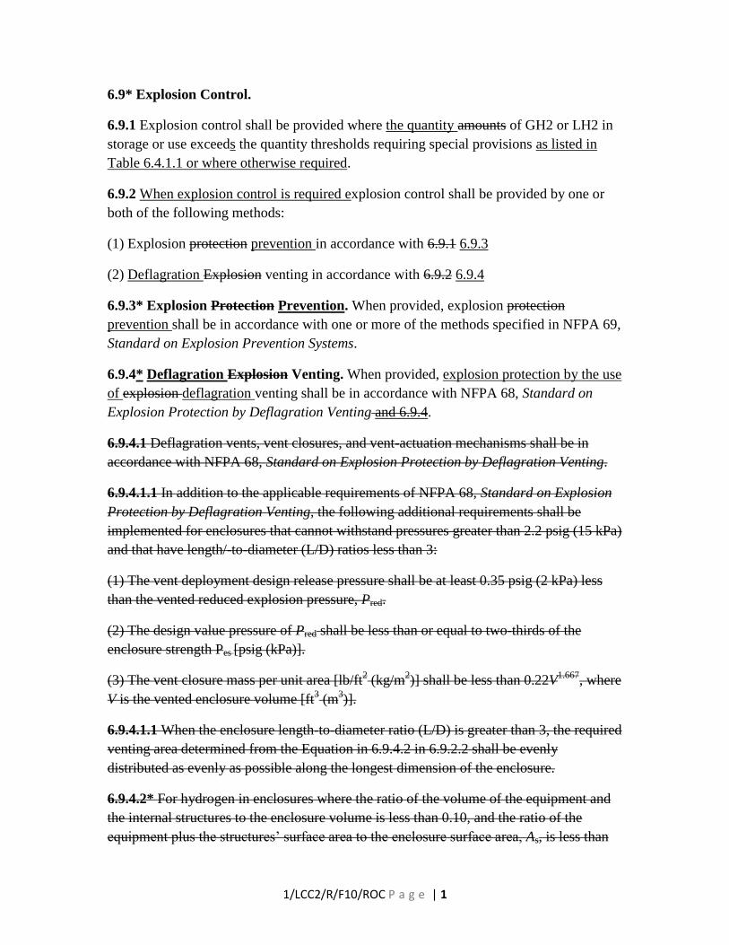
1/LCC2/R/F10/ROC P a g e | 1
6.9* Explosion Control.
6.9.1 Explosion control shall be provided where the quantity amounts of GH2 or LH2 in
storage or use exceeds the quantity thresholds requiring special provisions as listed in
Table 6.4.1.1 or where otherwise required.
6.9.2 When explosion control is required explosion control shall be provided by one or
both of the following methods:
(1) Explosion protection prevention in accordance with 6.9.1 6.9.3
(2) Deflagration Explosion venting in accordance with 6.9.2 6.9.4
6.9.3* Explosion Protection Prevention. When provided, explosion protection
prevention shall be in accordance with one or more of the methods specified in NFPA 69,
Standard on Explosion Prevention Systems.
6.9.4* Deflagration Explosion Venting. When provided, explosion protection by the use
of explosion deflagration venting shall be in accordance with NFPA 68, Standard on
Explosion Protection by Deflagration Venting and 6.9.4.
6.9.4.1 Deflagration vents, vent closures, and vent-actuation mechanisms shall be in
accordance with NFPA 68, Standard on Explosion Protection by Deflagration Venting.
6.9.4.1.1 In addition to the applicable requirements of NFPA 68, Standard on Explosion
Protection by Deflagration Venting, the following additional requirements shall be
implemented for enclosures that cannot withstand pressures greater than 2.2 psig (15 kPa)
and that have length/-to-diameter (L/D) ratios less than 3:
(1) The vent deployment design release pressure shall be at least 0.35 psig (2 kPa) less
than the vented reduced explosion pressure, Pred.
(2) The design value pressure of Pred shall be less than or equal to two-thirds of the
enclosure strength Pes [psig (kPa)].
(3) The vent closure mass per unit area [lb/ft2 (kg/m
2)] shall be less than 0.22V
1.667, where
V is the vented enclosure volume [ft3 (m
3)].
6.9.4.1.1 When the enclosure length-to-diameter ratio (L/D) is greater than 3, the required
venting area determined from the Equation in 6.9.4.2 in 6.9.2.2 shall be evenly
distributed as evenly as possible along the longest dimension of the enclosure.
6.9.4.2* For hydrogen in enclosures where the ratio of the volume of the equipment and
the internal structures to the enclosure volume is less than 0.10, and the ratio of the
equipment plus the structures’ surface area to the enclosure surface area, As, is less than

1/LCC2/R/F10/ROC P a g e | 2
0.15, the minimum required vent area, Av [ft2 (m
2)], shall be determined by the following
equation:
where:
Av=CAs/Pred1/2
C = venting parameter [psig1/2
(kPa1/2
)] = [0.47 psig1/2
(1.22 kPa1/2
)
Av = vent area [ft2 (m
2)]
As = internal surface area of enclosure as described in 7.2.4 of NFPA 68,, Standard on
Explosion Protection by Deflagration Venting [ft2 (m
2)]
Pred red = maximum pressure developed in the vented deflagration [psig (kPa)]
6.9.4.2.1* The use of deflagration venting shall not be permitted for enclosures in which
the ratio of the aggregate volume of the equipment and plus the volume of the internal
structures to the enclosure volume of the enclosure is greater than 0.10, or where the ratio
of the aggregate surface area of the equipment plus the surface area of the internal
structures plus the structures’ surface area to the internal surface area of the enclosure
surface area, As, is greater than 0.15.
6.9.4.2.2* The use of a A lower value of C shall be permitted for the enclosures described
in 6.9.2.2 when a documented risk hazard analysis shows that the potential for hydrogen
in the flammable cloud in a concentration greater than 19% by volume requires the
failure of at least two independent methods of control utilized by the design. average
hydrogen concentration in the flammable cloud used as the design basis for the hydrogen
release scenario is not greater than 19 percent by volume.
6.9.4.2.2.1 When the venting parameter, C, is established through the use of a
documented evaluation, the documentation shall be subject to review and approval by the
AHJ.
A.6.9.4 In addition to the applicable requirements of NFPA 68, Standard on Explosion
Protection by Deflagration Venting, the following additional requirements should be
implemented for enclosures that cannot withstand pressures greater than 2.2 psig (15 kPa)
and that have length-to-diameter (L/D) ratios less than 3:
(1) The vent design release pressure should be at least 0.35 psig (2 kPa) less than the
vented reduced explosion pressure, Pred.
(2) The design pressure of Pred should be less than or equal to two-thirds of the enclosure
strength Pes [psig (kPa)].

1/LCC2/R/F10/ROC P a g e | 3
(3) The vent closure mass per unit area [lb/ft2 (kg/m
2)] should be less than 0.22V
1.667,
where V is the vented enclosure volume [ft3 (m
3)].
When the enclosure length-to-diameter ratio (L/D) is greater than 3, the required venting
area determined from the Equation below should be evenly distributed along the longest
dimension of the enclosure.
For hydrogen in enclosures where the ratio of the volume of the equipment and the
internal structures to the enclosure volume is less than 0.10, and the ratio of the
equipment plus the structures’ surface area to the enclosure surface area, As, is less than
0.15, the minimum required vent area, Av [ft2 (m
2)], should be determined by the
following equation:
where:
Av=CAs/Pred1/2
C = venting parameter [psig1/2
(kPa1/2
)] = [0.47 psig1/2
(1.22 kPa1/2
)
Av = vent area [ft2 (m
2)]
As = internal surface area of enclosure as described in 7.2.4 of NFPA 68,, Standard on
Explosion Protection by Deflagration Venting [ft2 (m
2)]
Pred = maximum pressure developed in the vented deflagration [psig (kPa)]
Note: The equation above is the same as Equation 7.2.2 in NFPA 68, Standard on
Explosion Protection by Deflagration Venting. NFPA 68 does not provide values of C for
gases such as hydrogen with burning velocities greater than 60 cm/s. The presence of
numerous repeated obstacles, such as closely spaced piping and process vessels, can
cause highly accelerated flames and deflagration pressures that cannot be effectively
vented. The equation and C values are only applicable to relatively quiescent hydrogen–
air mixtures in relatively unobstructed enclosures without closely spaced piping and
process or storage vessels. The value of C in the equation is based on an analysis of
hydrogen deflagration tests in a 5.3 m3 enclosure as reported by Tanaka et al (2005).
NFPA 68, Standard on Explosion Protection by Deflagration Venting, Section 7.3, has a
different equation for determining deflagration vent areas for enclosures with Pred values
greater than 1.5 psig (10 kPa) [i.e., with strengths greater than 2.2 psig (15 kPa)].
The use of deflagration venting should not be permitted for enclosures in which the ratio
of the aggregate volume of the equipment plus the volume of the internal structures to the
volume of the enclosure is greater than 0.10, or where the ratio of the aggregate surface
area of the equipment plus the surface area of the internal structures to the internal
surface area of the enclosure, As, is greater than 0.15.

1/LCC2/R/F10/ROC P a g e | 4
Note: Obstructions that act as confinement increase the potential for explosions capable
of generating overpressures that might not be able to be vented without major damage to
the surrounding area.
The use of a lower value of C should be permitted when a documented hazard analysis
shows that the average hydrogen concentration in the flammable cloud used as the design
basis for the hydrogen release scenario is not greater than 19 percent by volume.
Note: Figure 7.2.2 of NFPA 68, Standard on Explosion Protection by Deflagration
Venting, shows that a value of C = 0.75 kPa1/2
(0.29 psi1/2
) is applicable to gases with a
fundamental burning velocity of 60 cm/s. Based on the burning velocity data in Figure
188 of Lewis and von Elbe’s Combustion, Flames, and Explosions of Gases, Academic
Press, 2nd
Edition, 1961, this value of C corresponds to a hydrogen concentration of
about 19 percent by volume. Hydrogen–air mixture burning velocity data and Figure
7.2.2 of NFPA 68, Standard on Explosion Protection by Deflagration Venting, can also
be used to determine C values for worst-case hydrogen concentrations below 19 percent
by volume.
When the venting parameter, C, is established through the use of a documented
evaluation, the documentation should be subject to review and approval by the AHJ.
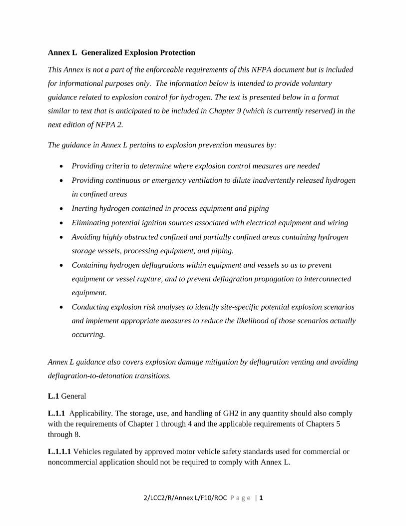
2/LCC2/R/Annex L/F10/ROC P a g e | 1
Annex L Generalized Explosion Protection
This Annex is not a part of the enforceable requirements of this NFPA document but is included
for informational purposes only. The information below is intended to provide voluntary
guidance related to explosion control for hydrogen. The text is presented below in a format
similar to text that is anticipated to be included in Chapter 9 (which is currently reserved) in the
next edition of NFPA 2.
The guidance in Annex L pertains to explosion prevention measures by:
Providing criteria to determine where explosion control measures are needed
Providing continuous or emergency ventilation to dilute inadvertently released hydrogen
in confined areas
Inerting hydrogen contained in process equipment and piping
Eliminating potential ignition sources associated with electrical equipment and wiring
Avoiding highly obstructed confined and partially confined areas containing hydrogen
storage vessels, processing equipment, and piping.
Containing hydrogen deflagrations within equipment and vessels so as to prevent
equipment or vessel rupture, and to prevent deflagration propagation to interconnected
equipment.
Conducting explosion risk analyses to identify site-specific potential explosion scenarios
and implement appropriate measures to reduce the likelihood of those scenarios actually
occurring.
Annex L guidance also covers explosion damage mitigation by deflagration venting and avoiding
deflagration-to-detonation transitions.
L.1 General
L.1.1 Applicability. The storage, use, and handling of GH2 in any quantity should also comply
with the requirements of Chapter 1 through 4 and the applicable requirements of Chapters 5
through 8.
L.1.1.1 Vehicles regulated by approved motor vehicle safety standards used for commercial or
noncommercial application should not be required to comply with Annex L.
2/LCC2/R/Annex L/F10/ROC P a g e | 2
L.2 Explosion Control
L.2.1 Explosion control should be provided where there are any of the following conditions:
(1) The amounts of GH2 or LH2 in storage or use exceed the quantity thresholds requiring
special provisions.
(2) At outdoor or partially confined locations when:
(A) the amount of GH2 or LH2 in storage or use exceed the quantity thresholds requiring
special provisions, as specified in Table 6.4.1 for indoor control areas, and
(B) where one or more of the following exist:
i) a flame acceleration hazard exists due to hydrogen being stored or used along
with piping and equipment in a congested space;
ii) the area containing the GH2 or LH2 is partially enclosed by either three or
more walls, or two walls plus a weather cover or ceiling.
An example of a congested space could be small regularly spaced obstacles such as a congested
equipment or piping array. The following list provides an approximate criteria to help identify
congested spaces where flame acceleration hazard would exist:
three or more rows or tiers of piping, spaced at less than ten to twelve pipe diameters;
three or more hydrogen process or storage units, spaced at one to five times the smallest
process/storage unit dimension.
The following references describe analysis methods to account for the effects of flammable gas
cloud volume and obstructions on pressures generated from vapor cloud explosions due to large
releases of flammable gas: Baker et al. (1997), Cleaver et al. (1997), Dorofeev, (2007a), Mercx
and van den Berg (1997), Pierorazio et al. (2005), and Tang and Baker (1999). Note:
Unconfined hydrogen explosions only occur with at least 40 kg hydrogen released into an
unobstructed open area in such a way that at least 20 kg develops near-stoichiometric
concentrations, or with at least 0.50 kg hydrogen into a highly obstructed areaTest data on
unconfined hydrogen deflagrations are available in the following references: Groethe et al.
(2005), Molkov et al. (2005), Wabayashi et al. (2005). The experiments of Groethe et al. showed
that blast walls constructed to protect equipment and structures behind them are only effective
for structures within a distance of two-to-three wall heights on the side of the wall away from the
hydrogen explosion.
Note: The threat of a hydrogen explosion in a partially confined area depends on the hydrogen
concentration distribution, potential ignition sources, the amount of confinement, the enclosure
length/diameter ratio and the presence of various types of obstructions. Although there are no

2/LCC2/R/Annex L/F10/ROC P a g e | 3
definitive research results for every quantitative value and combination of these four
parameters,there has been extensive research and guidelines on the congestion levels and gas
burning velocities that are conducive to hydrocarbon vapor cloud explosionssee Baker-Strehlow-
Tang (20xx) and Zalosh (2008) has provided a comprehensive review of the effects of different
types and quantities of obstructions on the pressures developed in vented hydrocarbon gas
explosions. As an example these reviews indicate that closely spaced piping at three or more
elevations and evenly spaced small equipment represent the type of congestion that allows
explosions to develop in open or partially confined areas. Test data and computational models
providing data and calculations to assess the effects of certain important ranges of hydrogen
concentrations, confinement and obstruction configurations, and ignition source locations in
partially confined areas are available in the following references: Friedrich et al. (2007),
Schneider (2005), Shirvill and Roberts (2007), and Tanaka et al. (2005).
(3) Indoors or in enclosures if the static volume of GH2 or LH2(STP) contained in a process or
transported in piping systems in the enclosure is equal to or greater than 0.004 (0.4%) times the
enclosure volume and the piping or container or equipment is disconnected during normal
operations while at least some hydrogen remains pressurized .
Note: Hydrogen-air deflagrations can occur when a flammable hydrogen-air mixture
encounters a capable ignition source in an enclosure. The likelihood of formation of a
flammable hydrogen-air mixture depends on the likelihood of releasing hydrogen at a rate and
location such that it cannot be readily or rapidly diluted below the lower flammable limit. Since
the existing NFPA standards do not contain a systematic and general description of the risk of a
hydrogen deflagration occurring, the Hydrogen Technologies Committee has generated the
deflagration risk criteria in Section L.4 based on semi-quantitative considerations of the risk of a
hydrogen release, and the following quantitative determination of the minimum amount of
hydrogen required to produce enclosure damage and injuries once ignited in an enclosure.
The least amount of flammable gas that can produce deflagration pressure damage can be
determined from considerations of partial volume deflagrations in which a local flammable
mixture exists in an enclosure in which most of the enclosure volume has concentrations below
the lower flammable limit. The deflagration pressure, P, produced from ignition at atmospheric
pressure, Patm, of a local near-stoichiometric mixture of volume, Vpv, in an enclosure of volume,
V, is given by the following equation (see Ogle, 1999, and Jo and Park, 2004).
1
exp1
atm
pvpv
atm P
P
V
V
V
V
P
P
where Pexp is the deflagration explosion pressure corresponding to a uniform near-
stoichiometric gas mixture throughout the enclosure, and γ is the gas mixture ratio of specific
heats.

2/LCC2/R/Annex L/F10/ROC P a g e | 4
Values of Pexp/Patm and γ for a stoichiometric hydrogen-air mixtures (29.6 % volume hydrogen in
dry air), and for hydrogen-air mixtures with hydrogen concentrations in the range 25.15 volume
% to 33.5 volume %) have been obtained using the GASEQ software package. Using these
values of Pexp/Patm and γ, the equation above has been used to calculate P (kPa g) as a function
of the partial volume fraction Vpv/V. Results are shown in Figure L.4.1.2a. The curves of P
versus partial volume fraction are linear for partial volume fractions less than about 0.08
because the preceding equation can be approximated as
atm
pv
atm P
P
V
V
P
P exp1
for these small values of Vpv/V.
Figure L.5a Hydrogen deflagration pressure versus flammable hydrogen-air mixture
partial volume fraction for three different hydrogen concentrations
The volume of hydrogen in the locally uniform hydrogen-air mixture partial volume is
given by χH2Vpv, where χH2 is the volume fraction of hydrogen in the near-stoichiometric
hydrogen-air mixture. If the hydrogen concentration distribution in the enclosure is
idealized as a sharp discontinuance boundary between the locally uniform flammable gas
mixture and the air in the rest of the enclosure, the volume of hydrogen in the enclosure
Deflagration Pressure vs Partial Volume Fraction
0
10
20
30
40
50
60
70
80
90
100
0.00 0.01 0.02 0.03 0.04 0.05 0.06 0.07 0.08 0.09 0.10 0.11 0.12 0.13 0.14 0.15 0.16 0.17 0.18 0.19 0.20
Partial Volume Fraction
De
fla
gra
tio
n P
res
su
re (
kP
a)
Stoichiometric Mixture
25% H2-Air Mixture
31.6% H2-Air Mixture

2/LCC2/R/Annex L/F10/ROC P a g e | 5
is given by χH2(Vpv/V). Figure L.5b is a plot of the deflagration P (kPa g) versus
χH2(Vpv/V), which is the ratio of the hydrogen volume to the enclosure volume.
Figure L.5b Hydrogen partial volume deflagration pressure versus ratio of hydrogen
volume to enclosure volume for different hydrogen partial volume concentrations.
The minimum hydrostatic pressure at which limited minor structural damage can occur is
approximately 0.4 to 0.5 psig (2.8 to 3.5 kPa) according to Tables 2.18a and 2.18b of the
CCPS Guidelines for Chemical Process Quantitative Risk Analysis, 2nd
Edition.
Therefore, injuries to any exposed personnel due to broken glass and other debris from
minor structural damage can be anticipated at pressures at and above about 4 kPa (0.58
psig). A horizontal line at about 4 kPa in Figure L.5b intersects the curve for a 25%
partial volume deflagration at a ratio of hydrogen volume to enclosure volume of about
0.004. The intersection for the stoichiometric mixture concentration occurs at a slightly
higher ratio of χH2(Vpv/V). Therefore, the hydrogen volume that can, in principle, cause
minor damage and injuries is 0.4 volume percent, i.e. at about 1/10th
LFL if the hydrogen
volume was uniformly distributed throughout the enclosure volume.
As an example, consider a hydrogen vehicle repair garage containing a single hydrogen
fueled vehicle with a 80 liter fuel tank containing hydrogen at an absolute pressure of 34
MPa. The volume of room temperature hydrogen corresponding to the release of the
tank contents through an inadvertently actuated pressure relief device is equal to (0.080
Deflagration Pressure vs Partial Volume Fraction
0
10
20
30
40
50
0.00 0.01 0.01 0.02 0.02 0.03 0.03 0.04 0.04 0.05 0.05
Hydrogen Volume/ Enclosure Volume
De
fla
gra
tio
n P
res
su
re (
kP
a)
Stoichiometric Mixture
25% H2-Air Mixture
31.6% H2-Air Mixture
2/LCC2/R/Annex L/F10/ROC P a g e | 6
m3 H2)(34 MPa)/(0.101 MPa) = 26.93 m
3 H2. The minimum repair garage volume to
prevent the ratio of hydrogen volume to enclosure volume from reaching 0.004 is equal
to 26.93 m3/0.004 = 6733 m
3 = 238,000 ft
3. This volume is larger than the volume of a
garage with a footprint of 100 ft x 100 ft (30.5 m x 30.5 m) and a ceiling height of 20 ft
(6.1 m).
L.2.2 Explosion Control Methods
L.2.2.1 Explosion Protection. Where explosion control is recommended by L.2.1, explosion
protection should consist of one or more of the following:
1) deflagration prevention by gas concentration reduction per L.2.2.3
2) deflagration prevention by oxidant concentration reduction per L.2.2.4
3) deflagration venting per L.2.2.5
4) deflagration containment per L.2.2.6.
Note: In addition to the explosion control measures, the control of ignition sources will decrease
the potential for an explosion. Typical ignition sources include thermal, mechanical, electrical,
electrostatic. The use of ignition control measures to address these sources will not eliminate the
potential for spontaneous ignition.
Electrical ignition sources can be mitigated by utilizing the requirements for electrical
equipment and wiring in classified locations in accordance with Article 500 of NFPA 70. NFPA
497 provides guidance for establishing classified locations.
Through the exercise of ingenuity in the layout of electrical installations for hazardous
(classified) locations, it is frequently possible to locate much of the equipment in a reduced level
of classification or in an unclassified location and, thus, to reduce the amount of special
equipment required. It is important that the authority having jurisdiction be familiar with
recorded industrial experience as well as with the standards of the National Fire Protection
Association (NFPA), the American Petroleum Institute (API), and the Instrumentation, Systems,
and Automation Society (ISA) that may be of use in the classification of various locations, the
determination of adequate ventilation, and the protection against static electricity and lightning
hazards.
Electrostatic ignition can be controlled by utilizing the methods identified in NFPA 77,
Recommended Practice on Static Electricity.

2/LCC2/R/Annex L/F10/ROC P a g e | 7
Other potential ignition sources including, but not limited to smoking, open flames, heating and
spark producing equipment should be eliminated or located a safe distance from potential leak
sources.
L.2.2.1.1 The explosion protection methods specified in L.2.2.1 may be partially or totally
eliminated where supported by an approved hazard analysis.
Note: The hazard analysis should give consideration to the following:
(1) The location of the storage system and associated exposures
(2) The potential for deflagration to detonation transition
(3) Prevention of pressurized equipment and piping breaches or releases
(4) Identification of additional preventive measures
(5) Identification of additional mitigation controls
(6) Documented test data applicable to the identified scenarios
L.2.2.1.1.1 The hazard analysis should identify and document the applicable explosion hazard
scenarios.
L.2.2.1.1.2 The hazard analysis should be validated by qualified personnel with proven expertise
in hazard analysis and should be subject to approval by the AHJ.
Note: For hydrogen, reliance upon prevention of ignition by controlling ignition sources is not
sufficient by itself due to the low ignition energy of ignitable clouds of GH2 and the fact that
certain releases can self-ignite due to buildup and discharge of static electricity. Therefore,
control of ignition sources must be combined with either fuel reduction (typically) by ventilation
of the area to lower GH2 concentration or by deflagration venting, or both to achieve sufficient
defense in depth.
L.2.2.1.1.3 When the hazard analysis has determined that there is a potential deflagration-to-
detonation transition (DDT) the system parameters should be redesigned to eliminate the hazard.
L.2.2.2 Deflagration Prevention by Hydrogen Gas Concentration Reduction
L.2.2.2.1 Deflagration prevention by gas concentration reduction can be considered where a
mixture of a combustible material and an oxidant is confined to an enclosure and where the
concentration of the hydrogen can be maintained below the lower flammable limit (LFL) of
hydrogen (4.0 volume percent at room temperature and pressure).
Note: See NFPA 69 Annex B for a discussion of the control of flammable gas mixtures. See also
NFPA 69 Annex D for information on calculating the time required for concentration reduction
by ventilation.

2/LCC2/R/Annex L/F10/ROC P a g e | 8
L.2.2.2.2 Deflagration prevention by hydrogen gas concentration reduction should be in
accordance with NFPA 69, Chapter 8 as supplemented by L.2.2.2.3.
L.2.2.2.3 Design Considerations.
L.2.2.3.2.1 The following factors should be considered in the design of a system intended to
reduce the combustible concentration below the LFL:
(A) Ventilation or Air Dilution. (69:8.2.3)
(1) If ventilation is used, the outlets from the protected enclosures should be located so that
hazardous concentrations of the exhausted air cannot enter or be drawn into the fresh air
intakes of environmental air-handling systems. (69:8.2.3.1)
(2) The ventilation rate for hydrogen dilution should be based on a hydrogen release rate
equal to either i) the storage pressure and an orifice diameter equal to 3 percent of the
diameter of the largest hydrogen piping or equipment connection, or ii) a risk-based
analysis of release rates for the type of hydrogen piping and equipment in the room or
building.
Note: The 3 percent of the pipe diameter requirement is based on the hydrogen leakage rate
conditions described in NFPA 2 Annex paragraph E.1.
L.2.2.3 Oxygen concentration reduction below the 3 volume percent hydrogen Limiting
Oxygen Concentration (LOC)
L.2.2.3.1 Application. Oxygen concentration reduction can be considered where a mixture of
oxidant and hydrogen is confined to an enclosure within which the oxidant concentration can be
controlled. (69:7.1)
L.2.2.3.2 Oxygen concentration reduction should be in accordance with NFPA 69, Chapter 7 as
supplemented by L.2.2.3.3.
L.2.2.2.3 Design Considerations.
L.2.2.3.2.1 The following factors should be considered in the design of an oxygen concentration
reduction system:
(A) Limiting Oxidant Concentration (LOC). (69:7.2.3)
1) The hydrogen LOC depends on the inert gas used, the flammability test method, and
the initial temperature and pressure.
2) The LOC for nitrogen inerting at standard temperature and pressure is 3.0% ocygen.

2/LCC2/R/Annex L/F10/ROC P a g e | 9
3) The LOC for carbon dioxide inerting at standard temperature and pressure is 3.2%
oxygen.
4) The LOC value for other inert gases, temperatures and pressures should be measured
according to ASTM E 2079, Standard Test Method for Limiting Oxygen (Oxidant)
Concentration for Gases and Vapors. (69:7.2.3.1.1)
5) The use of oxidants other than oxygen may also require further investigation with
respect to the limiting oxidant concentration.
6) The design concentration should be a fraction of the LOC per NFPA 69-7.7.2.5 and
7.7.2.7.
Note: The LOC values for nitrogen and carbon dioxide are the adjusted values for hydrogen
from Table C.1(a) of NFPA 69.
L.2.2.4 Deflagration Venting
L.2.2.4.1 Hydrogen deflagration venting for limiting explosion damage should be in accord with
the requirements in Section 6.9 of this standard and NFPA 68.
L.2.2.5 Deflagration Containment
L.2.2.5.1 Application. Deflagration containment can be considered for specifying the design
pressure of a vessel and its appurtenances so they are capable of withstanding the maximum
pressures resulting from an internal hydrogen deflagration.(69:13.1.1)
L.2.2.5.2 Deflagration containment should be in accordance with NFPA 69, Chapter 13 as
supplemented by L.2.2.5.3.
L.2.2.5.3 Design Considerations.
L.2.2.3.2.1 The following factors should be considered in the design of an deflagration venting
system:
(A) Containment Design Basis
1. The deflagration containment design basis should be as described in NFPA 69 Section
13.3.
2. The value of the hydrogen-air deflagration pressure ratio R needed for the NFPA 69
Section 13.3 design basis is 8.3. Another value of the deflagration pressure ratio R can be
used if a documented analysis of worst case hydrogen concentrations shows that near-
stoichiometric hydrogen-air concentrations cannot occur.

2/LCC2/R/Annex L/F10/ROC P a g e | 10
3. The value of the hydrogen-oxygen deflagration pressure ratio R needed for the NFPA
69 Section 13.3 design basis is 9.6. Another value of the deflagration pressure ratio R can
be used if a documented analysis of worst case hydrogen concentrations shows that near-
stoichiometric hydrogen-oxygen concentrations cannot occur.
4. Where either deflagration venting or deflagration containment are relied on as
exclusive control measure(s) for explosion protection a documented risk assessment
should be performed to evaluate the potential for a deflagration- to-detonation transition
(DDT) when any of the following conditions exist:
a) the ratio of the volume of the equipment plus the volume of internal structures
within the enclosure to the volume of the enclosure is greater than 0.10,
b) the ratio of surface area of the equipment plus the surface area of internal
structures to the surface area of the enclosure (As) is less than 0.15,
c) there are uniformly spaced objects or obstacles including piping or equipment
that obstruct more than 40% of the enclosure cross-section based on the least
dimension of the space, or
Note: Uniformly spaced objects may include piping or equipment arranged in a repetitive
manner such that the explosive effects are magnified as the flame propagates around these
objects.
d) the enclosure length to diameter ratio is greater than 5.
Note: The potential for deflagration-to-detonation transition (DDT) in obstructed or elongated
enclosures is a complex subject often requiring expert analysis. Some of the contemporary
references on this subject include the following:
Dorofeev (2007b); Hansen et al. (2005); Lee and Berman (1997); Pethukov et al. (2007);
Sherman and Berman (1988); Zalosh (FPRF report).
L.3 Explosion Prevention
L.3.1 GH2 or LH2 shall not be intentionally released from storage or use systems into areas
where congested piping systems are present.
L3.2 Hydrogen Explosions in Piping, Electrical Conduit, and Ducting
L.3.2.1 Piping and Tubing Explosion Hazards and Protection
L.3.2.1.1 An evaluation should be conducted to determine the potential of an adverse reaction
where any of the following conditions exist:

2/LCC2/R/Annex L/F10/ROC P a g e | 11
1. The formation of a mixture of hydrogen with atmospheric pressure air within piping
which has a design pressure rating of less than 300 psi.
2. The formation of a mixture of hydrogen with greater than atmospheric pressure air.
3. A hydrogen-oxygen mixture within piping or tubing can occur.
4. Where piping may be filled with air and is purged with hydrogen.
5. There is a potential for degradation of fittings, gaskets, valves, etc due to hydrogen
embrittlement.
Note: If the process requires the hydrogen piping or tubing to carry a flammable mixture during
any stage of operation, the ability of the piping to withstand a hydrogen explosion should be
evaluated and, if necessary, strengthened to prevent pipe failure.
Methods to assess the structural response of piping and tubing to deflagrations and detonations
are described by Shepherd (2006).
Hydrogen compatibility and embrittlement information is provided in documents such as
SAND2008-1163, Technical Reference on Hydrogen Compatibility of Materials.
L.3.2.1.2 Corrective actions should be taken to reduce the likelihood of any significant adverse
consequences of flammable mixture formation in piping.
L.3.2.1.3 Where piping connects two or more process vessels or equipment in which there are
explosion hazards, the piping should be equipped with in-line deflagration arresters per NFPA 69
Sections 12.2.4, 12.2.5, or 12.2.6.
L.3.3 Electrical Conduit Explosion Hazards and Protection
L.3.3.1 Electrical conduit and connectors in electrically classified (Class 1) areas should be
installed per NFPA 70.
L.3.4 Hydrogen Explosion Hazards and Protection for Ducting
L.3.4.1 The hydrogen concentration in exhaust ducting during normal operating conditions
should not exceed 1 volume percent unless the duct and exhaust system are designed in accord
with NFPA 69, Standard on Explosion Prevention System.
L.3.4.2 Higher hydrogen concentrations may be permitted for oven and furnace ducting if the
ducting is designed in accord with NFPA 86, Standard for Ovens and Furnaces.
L.3.4.3 Operations generating flames, sparks, or hot material such as from grinding wheels and
welding should not be manifolded into any duct system potentially containing hydrogen.
2/LCC2/R/Annex L/F10/ROC P a g e | 12
L.3.4.4 Where ferrous materials can enter ducting carrying hydrogen, magnetic separators should
be installed.
L.3.4.5 Ducting carrying hydrogen should be grounded.
L.3.5 Inspection of Hydrogen Pressure Vessels and Piping
L.3.5.1 Hydrogen pressure vessels and piping should be inspected in accordance with the
requirements of the code to which they were built. Where such inspection requirements are not
provided, the owner of the pressure vessels should implement a mechanical integrity program.
L.3.5.1.1 The mechanical integrity program should consider the impact of hydrogen enhanced
fatigue crack growth when the pressure vessels are in cyclic service.
References
ASME Boiler and Pressure Vessel Code, American Society of Mechanical Engineers.
ASME B31.12, (2008) “Hydrogen Piping and Pipelines,” American Society of Mechanical
Engineers.
Baker, W., Cox, P., Westine, P., Kulesz, J., and Strehlow, R. (1983) Explosion Hazards and
Evaluation, Elsevier.
Baker, Q., Doolittle, C., Fitzgerald, G. and Tang, M. (1997). Recent Developments in the Baker-
Strehlow VCE Analysis Methodology. 31st Annual AIChE Loss Prevention Symposium.
Center for Chemical Process Safety, Guidelines for Chemical Process Quantitative Risk
Assessment, 2nd
Edition, AIChE, 2000.
Center for Chemical Process Safety, Guidelines for Hazard Evaluation Procedures, 2nd
Edition,
AIChE, 1992.
CGA P-28, “Risk Management Plan Guidance Document for Bulk Liquid Hydrogen Systems,”
2nd
Edition, Compressed Gas Association, 2003.
Cleaver, R., Humphreys, C., Morgan, J. and Robinson, C. (1997). "Development of a model to
predict the effects of explosions in compact congested regions." Journal of Hazardous Materials
53: 35-55.
Davison, J., Porter, J., Dinan, R., Hammons, M., and Connell, J., “Explosive Testing of Polymer
Retrofit Masonry Walls,” Journal of Performance of Constructed Facilities, v. 12, pp. 100-106,
2004.
Dorofeev, S. (2007a). "A Flame Speed Correlation for Unconfined Gaseous Explosions."
Process Safety Progress 26(2): 140-149.
2/LCC2/R/Annex L/F10/ROC P a g e | 13
Dorofeev, S. (2007b). Hydrogen Flames In Tubes: Critical Run-Up Distances. 2nd International
Conference on Hydrogen Safety. San Sebastian, Spain.
Environmental Protection Agency, Risk Management Plan Regulation, Code of Federal
Regulations (CFR) 40 CFR 68.130, see also
http://www.epa.gov/oem/content/rmp/rmp_guidance.htm#General.
Groethe, M. et al. (2005) “Large Scale Hydrogen Deflagrations and Detonations,” International
Conference on Hydrogen Safety.
Friedrich A. et al. (2007) “Experimental Study of Hydrogen-Air Deflagrations in a Flat Layer,”
2nd
International Conference on Hydrogen Safety, San Sebastion, Spain.
Hansen, O., Renoult, J., Sherman, M., and Tieszen, S., (2005) “Validation of FLACS-Hydrogen
CFD Consequence Prediction Model Against Large Scale H2 Explosion Experiments in the
FLAME Facility,” International Conference on Hydrogen Safety
Jo, Y.-D. and Park, K-S. (2004). "Minimum Amount of Flammable Gas for Explosion within a
Confined Space." Process Safety Progress 23: 321-329.
M. Kaneshige and J.E. Shepherd., Detonation database, Technical Report FM97-8, GALCIT,
July 1997. See also the electronic hypertext version at
http://www.galcit.caltech.edu/detn_db/html/.
Knox, K., Hammons, M., Lewis, T. and Porter, J. (2004) “Polymer Materials for Structural
Retrofit,” Air Force Research Laboratory Report.
Lee, J. and Berman, M. (1998) “Hydrogen Combustion and Its Application to Nuclear Reactor
Safety,” Advances In Heat Transfer, v 29.
Mays, G. C., and Smith, P. D. (1995). Blast effects on buildings—Design of buildings to optimise
resistance to blast loading. Thos. Telford, London
Mercx, W., and van den Berg, A. (1997). The Explosion Blast Prediction Model in the Revised
"Yellow Book". 31st Annual AIChE Loss Prevention Symposium.
Molkov, V., Makarov, D. and Schneider, H. (2005). Hydrogen-Air Deflagrations in Open
Atmosphere: Large Eddy Simulation of Experimental Data. 1st International Conference on
Hydrogen Safety. Pisa, Italy.
Ng, H.D., Ju, Y., and Lee, J., “Assessment of Detonation Hazards in High-Pressure Hydrogen
Storage from Chemical Sensitivity Analysis, Intl. Journal of Hydrogen Energy, 2006.

2/LCC2/R/Annex L/F10/ROC P a g e | 14
OECD Nuclear Energy Agency, Flame Acceleration and Deflagration to Detonation
Transition in Nuclear Safety , State-of-the-Art Report by a Group of Experts, OECD Nuclear
Energy Agency, NEA/CSNI/R(2000)7, August 2000
Ogle, R. (1999). "Explosion Hazard Analysis for an Enclosure Partially Filled With a Flammable
Gas." Process Safety Progress 18: 170-177.
Petukhov, V.A., Naboko, I.M. and Fortov, V.E., (2007) “Explosion Hazard Of Hydrogen-Air
Mixtures In The Large Volumes,” 2nd
International Conference on Hydrogen Safety
Pierorazio, J., Thomas, Q., Baker, Q. and Ketchum, D. (2005). "An Update to the Baker-
Strehlow-Tang Vapor Cloud Explosion Prediction Methodology Flame Speed Table." Process
Safety Progress 24: 59-65.
Schneider, H. (2005) “Large Scale Experiments: Deflagration and Deflagration to Detonation
within a Partial Confinement Similar to a Lane,” 1st Intl. Conference on Hydrogen Safety, Pisa,
Italy.
Shepherd, J. (2006) “Elastic and Plastic Structural Response of Tubes to Deflagration-to-
Detonation Transition,” California Institute of Technology Explosion Dynamics Laboratory
Report FM2006-00X.
Sherman, M. and Berman, M. (1987) “The Possibility of Local Detonations during Degraded-
Core Accidents in the Bellefonte Nuclear Power Plant,” Nuclear Technology, v 18, pp. 63-77.
Shirvill, L. C. R., M.and Roberts, T.A. (2007). Hydrogen Releases Ignited In A Simulated
Vehicle Refuelling Environment, 2nd International Conference on Hydrogen Safety San
Sebastian, Spain
Smith, P. D., and Hetherinton, J. G. (1994). Blast and ballastic loading of structures.
Butterworth-Heinemann, Oxford, U.K.
Tanaka, T. et al. (2005) “Experimental Study on Hydrogen Explosions in a Full-Scale Hydrogen
Filling Station Model, 1st Intl. Conference on Hydrogen Safety, Pisa, Italy.
Tang, M. and Baker, Q. ( 1999). A New Set of Blast Curves from Vapor Cloud Explosions. 33rd
Annual AIChE Loss Prevention Symposium.
Wabayashi, et al. (2005) “A Field Explosion Test of Hydrogen-Air Mixtures,” International
Conference on Hydrogen Safety.
Zalosh, R. (2005) “Blast Waves and Fireballs Generated by Hydrogen Fuel
Tank Rupture During Fire Exposure,” 5th
International Fire and Explosion Hazards Seminar,
Edinburgh.

2/LCC2/R/Annex L/F10/ROC P a g e | 15
Zalosh, R. (2007) “Explosion Venting Data and Modeling Literature Review,” Fire Protection
Research Foundation Report.
Zlochower, I. and. Green, G. (2009). "The limiting oxygen concentration and flammability limits
of gases and gas mixtures." Journal of Loss Prevention in the Process Industries 22: 499-505.
Report on Comments – November 2010 NFPA 2_______________________________________________________________________________________________2-99 Log #175
_______________________________________________________________________________________________Glenn Mahnken, FM Global
2-1Add new text as follows:
Explosion control shall be provided where amounts of GH2 or LH2 in storage or use exceed the quantitythresholds requiring special provisions or, for lesser quantities if an explosion involving hydrogen could result insignificant damage to a facility or serious injuries to personnel within the control area.
The determination of the degree of hazard presented by a specific operation is a matter of judgment. Anexplosion hazard should be evaluated in terms of likelihood, severity, and the consequences of an explosion, as well asthe protection required to substantially reduce the hazard. A review of the explosion hazard analysis by an appropriatelevel of management is recommended. [ C.4.1]
Explosion hazards may be present in control areas even if the quantity is less than the MAQ. Thishazard is recognized by NFPA 45 (Laboratories) and could be present in other occupancies as well. An explosionhazards analysis should be conducted according to guidelines in NFPA 45.
The proposed language is unenforceable as written. The NFPA 2 Task Group on explosionhazards is currently working to develop an approach that utilizes hazards analysis for future editions of the Code.Changes in this section would alter the intent of the material in NFPA 55, where this material is extracted from.
_______________________________________________________________________________________________2-100 Log #266
_______________________________________________________________________________________________Christopher Radley, Altergy Systems
2-1Revise text to read as follows:
Explosion protection in accordance with 6.9.1 6.9.3.Appears to be a typo pointing to the wrong section.
_______________________________________________________________________________________________2-101 Log #265
_______________________________________________________________________________________________Christopher Radley, Altergy Systems
2-1Revise text to read as follows:
Explosion protection in accordance with 6.9.2 6.9.4.Appears to be a typo pointing to the wrong section.
57Printed on 6/1/2010

Report on Comments – November 2010 NFPA 2_______________________________________________________________________________________________2-102 Log #106
_______________________________________________________________________________________________Larry L. Fluer, Fluer, Inc. / Rep. Compressed Gas Association
2-1Delete text as follows:
When provided, explosion venting shall be in accordance with NFPA 68,.
Deflagration vents, vent closures, and vent-actuation mechanisms shall be in accordance with NFPA 68,.
Section 6.9.4.1 is redundant to 6.9.4. If explosion venting is in accordance with NFPA 68 as requiredby 6.9.4 the vents, vent closures and actuation mechanisms should also be in accordance with NFPA 68. Repeating therequirement is not necessary.
See the committee action on 2-98 (Log #CC2), which addresses this change.
58Printed on 6/1/2010
Report on Comments – November 2010 NFPA 2_______________________________________________________________________________________________2-103 Log #176
_______________________________________________________________________________________________Glenn Mahnken, FM Global
2-1Revise text as follows:
Where GH2 detection systems are installed they shall be designed, installed, tested, inspected, calibrated andmaintained in accordance with one both of the following:
(1) Approved manufacturer’s requirements(2) Approved recognized industry standards
Testing shall not be required where approved written documentation is provided stating that testing willdamage the equipment, device, or system and the equipment, device, or system is maintained as specified by themanufacturer. GH2 detection systems shall be designed so that the system and all equipment and devices can beproof-tested without damage to any equipment, device or system or causing unsafe conditions.
Testing shall not be required for equipment, devices, and systems that fail in a fail-safe manner.]Maintenance, inspection, calibration and testing shall be conducted only by personnel trained and authorized by thesystem manufacturer.
Testing shall not be required for equipment, devices, and systems that self-diagnose and report trouble, andrecords of self-diagnosis and trouble reporting shall be made available to the AHJ. 2-21
The GH2 detection systems, equipment, and devices shall be tested, calibrated and inspected at 3-monthintervals. at one of the following frequencies: .
(1) Not less than annually(2) In accordance with the approved manufacturers’ requirements(3) In accordance with approved recognized industry standards(4) In accordance with an approved schedule
The frequency of inspection described in 16.12.2 shall be permitted to be increased or decreased based ondocumented operating experience or a documented hazard analysis, and only with approval of both the system designerand the AHJ.
Inspection, testing maintenance and calibration procedures shall be documented and copies shall beprovided to the AHJ and kept on file on the premises.
Scheduled maintenance, inspection, calibration and testing activities shall be formally documented, and recordsshall be maintained on the premises a minimum of 3 years for the life of the detection system or a shorter time period ifallowed by the AHJ.
Most manufacturers of approved GH2 detection systems recommend at least quarterly testing or calibration,but more frequent during the initial operating period.
Inspection and calibration are also necessary and should take into account both themanufacturers recommendations and practices in industry.
GH2 detection systems perform critical safety function - prevent hydrogen explosions. They should be able tobe tested routinely without being damaged.
Even “fail-safe” equipment can fail dangerously. Add requirement for qualified testers.Having self-diagnostic and trouble reporting capability does not necessarily mean a device, software or
system never needs to be proof tested.Most manufacturers recommend minimum 3-month intervals, with more frequent during start-up.
This allows for adjustments to the frequency based on experience, but requires AHJ Approval.Makes sure a copy of test procedures is provided to the AHJ and also kept on site.
Testing, maintenance, calibration and inspection activities and results need to be traceable over the life of theinstallation – in particular when trying to understand the cause(s) of system malfunctions.
A frequency statement was added to indicate common frequency recommendation of manufacturers
The proponent's concerns are addressed by 2-104 (Log #CC1).
59Printed on 6/1/2010
Report on Comments – November 2010 NFPA 2_______________________________________________________________________________________________2-104 Log #CC1
_______________________________________________________________________________________________Technical Committee on Hydrogen Technology,
2-1Revise the suggested text from Log#176 and insert new text as follows:
Gas detection equipment shall be listed or approved.Where GH2 detection systems are installed they shall be designed, installed, tested, inspected, calibrated and
maintained in accordance with one of the following:(1) Approved mManufacturer’s requirements(2) Approved recognized industry standardsEquipment listing requirements
Testing shall not be required where approved written documentation is provided stating that testing willdamage the equipment, device, or system and the equipment, device, or system is maintained as specified by themanufacturer.
Testing shall not be required for equipment, devices, and systems that fail in a fail-safe manner.]Testing shall not be required for equipment, devices, and systems that self-diagnose and report trouble, and
records of self-diagnosis and trouble reporting shall be made available to the AHJ. 2-21The GH2 detection systems, equipment, and devices shall be tested at one of the following frequencies: .
(1) Not less than annually(2) In accordance with the approved manufacturers’ requirements(3) In accordance with approved recognized industry standards(4) In accordance with an approved schedule
Scheduled maintenance, and testing activities shall be formally documented, and records shall be maintained aminimum of 3 years.
Maintenance, inspection, calibration and testing shall be conducted by trained personnel.Testing shall be conducted at least annually.
inspection, calibration, and testing records shall be retained for a minimum of 3 years.
Many manufacturers recommend at least quarterly testing or calibration, but more frequent tesing duringthe initial operating period. The installation of the detector in extreme or harsh environments may also warrant morefrequent testing.
6.12 Changed for consistency with the rest of the document.6.12.1 No requirement was previously identified for the listing of the gas detection equipment, so this was added.6.12.2 Changes were made to include inspection and calibration requirements. The concept of “approved”
manufacturer’s requirements was considered inappropriate and thus the word has been removed. Equipment listingrequirements were determined to be a better basis for testing as there are few, if any, industry standards for hydrogengas detectors.
6.12.1.1 through 6.12.3 have been removed and replaced with a new 6.12.2.1 through 6.12.2.1.2. These new sectionsbetter address the qualifications, frequency of documentation associated testing of these systems.
A.6.12.2.1.1 has been added to help the user understand that there may be circumstances requiring more frequentinspection and testing.
The committee believed that the 3 years being suggested is consistent with common industry practice.
60Printed on 6/1/2010
Report on Comments – November 2010 NFPA 2_______________________________________________________________________________________________2-105 Log #21
_______________________________________________________________________________________________Charles B. Henrici, Elk Grove Village Fire Dept.
2-1Revise text to read as follows:
Hydrogen venting systems discharging to the atmosphereshall be in accordance with CGA G-5.5, . [ 10.2.2]
The entire text of Section 10.2.2 of NFPA 55 was not extracted and formatted as required in proposal2-1 of the ROP.
It is important that the extracts are correct and complete so when an AHJ is challenged the code is correct and clear inits intent.
The committee believes that the existing title is more appropriate for use in NFPA 2.
_______________________________________________________________________________________________2-106 Log #264
_______________________________________________________________________________________________Christopher Radley, Altergy Systems
2-1Revise text to read as follows:
The gas cabinet shall be constructed of not less than 0.097 in. (2.46 mm) (12 gauge) steel or aluminum.For use with hydrogen, aluminum or steel should be acceptable materials of construction and are both
commonly used for enclosures with other applications. In addition, hydrogen will not react with or corrode aluminum. Asthe interior of the cabinet should have no ignition sources the cabinet is to act as a non-combustible barrier from outsideexposures similar to that defined in Sections 7.1.9.3.1 and 7.1.9.3.2.
Aluminum has a low melting point and would be inappropriate for use as a gas cabinet forflammable gases. The gas cabinet provides a degree of protection from external exposure fires and an aluminumcabinet would not provide an adequate level of protection for that purpose.
_______________________________________________________________________________________________2-107 Log #263
_______________________________________________________________________________________________Christopher Radley, Altergy Systems
2-1Delete this paragraph.
The quantity of tanks with no reference to volume, pressure, construction, MAQ, etc does not make asystem inherently safer. In addition, the use of 6 cylinders in a 6-pack configuration is a typical quantity for hydrogensystems used in industry.
The committee recognizes that the amount of hydrogen in a gas cabinet might be appropriatelylimited by the volume as opposed to the quantity of containers. The committee suggests that the proponent of this issueconsiders submitting a proposal to NFPA 55.
61Printed on 6/1/2010

Report on Comments – November 2010 NFPA 2_______________________________________________________________________________________________2-108 Log #262
_______________________________________________________________________________________________Christopher Radley, Altergy Systems
2-1Delete this paragraph.
Based on the discussion in A7.3.2.1.6, a sprinklered cabinet could result in a more unsafe condition.As hydrogen will not attack or corrode the cabinet material, a sprinkler system is not required to dilute the gas frominterfacing with the cabinet walls.
The sprinkler is intended to cool the cylinders in the event of an exposure fire to help preventcylinder failure. The use of sprinklers in exhausted enclosures allows for the storage of additional cylinders beyondthose allowed for an unsprinklered gas cabinet.
_______________________________________________________________________________________________2-109 Log #105
_______________________________________________________________________________________________Larry L. Fluer, Fluer, Inc. / Rep. Compressed Gas Association
2-1Revise the terminology used throughout Chapter 7 where the extract text refers in pertinent part to
compressed gas “containers, cylinders, and tanks” to format the text in a manner similar to that shown below in Section7.1.5.4 used as an example. Specifically, inserting the [GH2] term and striking the term “compressed gas” resolves theproblem.
[GH2] [compressed gas] containers, cylinders,and tanks containing residual product shall be treated as full except when being examined, serviced, or refilled by a gasmanufacturer or distributor. [ 7.1.5.4]
The following sections should be revised accordingly: 7.1.4.1.5, 7.1.9.7.2, 7.1.9.9, 7.1.9.10, 7.1.10, 7.1.11, 7.1.12,7.1.31.1, 7.1.13.3, 7.2.4.3, 7.3.2.4, 7.3.2.4.1.2(B).
Section 7.1.9.2.1 uses in pertinent part the term “compressed gas cylinders.” This section should be revised to [GH2][compressed gas] cylinders…
A consistent approach in the use of terms is warranted. The general term “compressed gas” has beenconverted to [GH2] in the formulation of the document. It is not necessarily applied to NFPA 2 universally, but itgenerally has been within Chapter 7. The suggested changes to Chapter 7 will bring consistency, and the changes areof an editorial nature.
_______________________________________________________________________________________________2-110 Log #22
_______________________________________________________________________________________________Charles B. Henrici, Elk Grove Village Fire Dept.
2-1Revise text to read as follows:
[GH2] [compressed gas] systems shall be designed for the intended use and shall bedesigned by persons competent in such design. [ 7.1.1.1]
Brackets need to be put around the word "System" because it was added to this extraction from NFPA55.
Titles are not required to follow the extract rules. The existing title is appropriate as written inNFPA 2.
62Printed on 6/1/2010
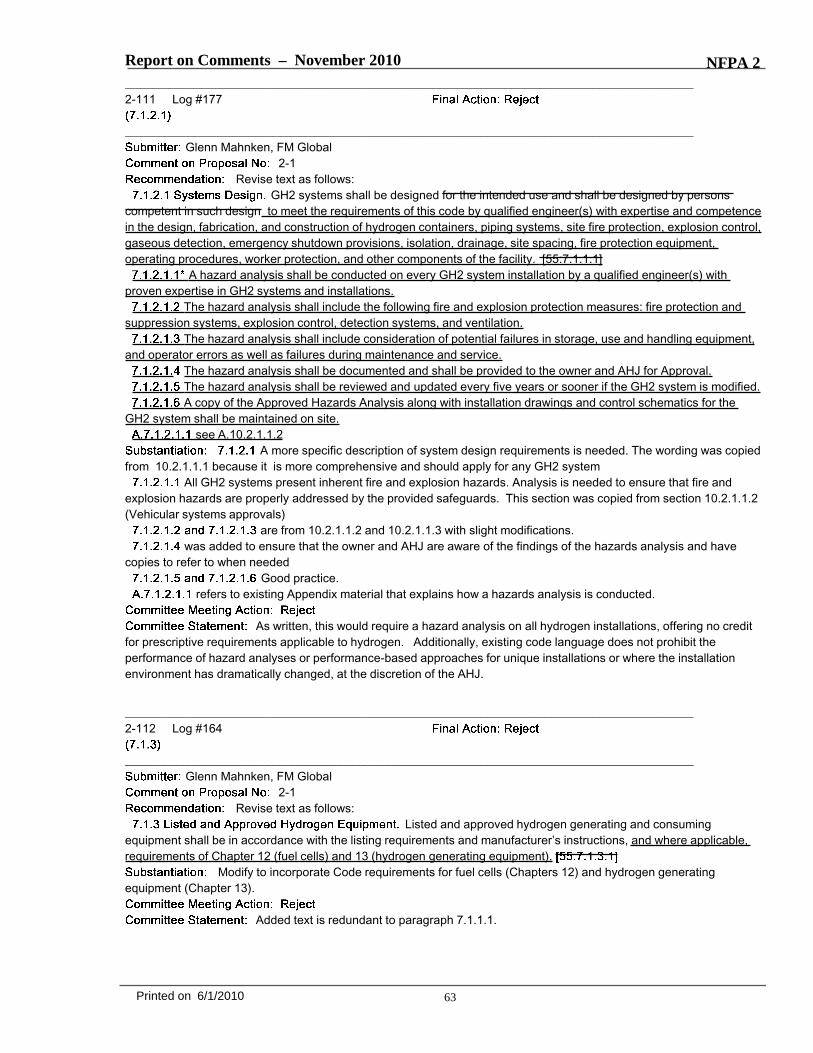
Report on Comments – November 2010 NFPA 2_______________________________________________________________________________________________2-111 Log #177
_______________________________________________________________________________________________Glenn Mahnken, FM Global
2-1Revise text as follows:
GH2 systems shall be designed for the intended use and shall be designed by personscompetent in such design to meet the requirements of this code by qualified engineer(s) with expertise and competencein the design, fabrication, and construction of hydrogen containers, piping systems, site fire protection, explosion control,gaseous detection, emergency shutdown provisions, isolation, drainage, site spacing, fire protection equipment,operating procedures, worker protection, and other components of the facility. [55:7.1.1.1]
A hazard analysis shall be conducted on every GH2 system installation by a qualified engineer(s) withproven expertise in GH2 systems and installations.
The hazard analysis shall include the following fire and explosion protection measures: fire protection andsuppression systems, explosion control, detection systems, and ventilation.
The hazard analysis shall include consideration of potential failures in storage, use and handling equipment,and operator errors as well as failures during maintenance and service.
The hazard analysis shall be documented and shall be provided to the owner and AHJ for Approval.The hazard analysis shall be reviewed and updated every five years or sooner if the GH2 system is modified.A copy of the Approved Hazards Analysis along with installation drawings and control schematics for the
GH2 system shall be maintained on site.see A.10.2.1.1.2
A more specific description of system design requirements is needed. The wording was copiedfrom 10.2.1.1.1 because it is more comprehensive and should apply for any GH2 system
All GH2 systems present inherent fire and explosion hazards. Analysis is needed to ensure that fire andexplosion hazards are properly addressed by the provided safeguards. This section was copied from section 10.2.1.1.2(Vehicular systems approvals)
are from 10.2.1.1.2 and 10.2.1.1.3 with slight modifications.was added to ensure that the owner and AHJ are aware of the findings of the hazards analysis and have
copies to refer to when neededGood practice.
refers to existing Appendix material that explains how a hazards analysis is conducted.
As written, this would require a hazard analysis on all hydrogen installations, offering no creditfor prescriptive requirements applicable to hydrogen. Additionally, existing code language does not prohibit theperformance of hazard analyses or performance-based approaches for unique installations or where the installationenvironment has dramatically changed, at the discretion of the AHJ.
_______________________________________________________________________________________________2-112 Log #164
_______________________________________________________________________________________________Glenn Mahnken, FM Global
2-1Revise text as follows:
Listed and approved hydrogen generating and consumingequipment shall be in accordance with the listing requirements and manufacturer’s instructions, and where applicable,requirements of Chapter 12 (fuel cells) and 13 (hydrogen generating equipment).
Modify to incorporate Code requirements for fuel cells (Chapters 12) and hydrogen generatingequipment (Chapter 13).
Added text is redundant to paragraph 7.1.1.1.
63Printed on 6/1/2010

Report on Comments – November 2010 NFPA 2_______________________________________________________________________________________________2-113 Log #120
_______________________________________________________________________________________________Larry L. Fluer, Fluer, Inc. / Rep. Compressed Gas Association
2-29Revise text to read as follows:
The storage and use of metal hydride storage systems shall be in accordance with 7.1.4. [ 7.1.4.1.1]Metal hydride storage systems used for fuel cell power supplies shall also be in accordance with the
applicable requirements of Chapter 12.Section 7.1.4 establishes fundamental requirements for metal hydride storage systems. Additional use
specific requirements when the storage systems become a component of a fuel cell power supply are found in Chapter12. The reference is intended to inform the user of specific requirements that are imposed in these unique applications.
Paragraph 7.1.1.1 already addresses this subject.
64Printed on 6/1/2010

Report on Comments – November 2010 NFPA 2_______________________________________________________________________________________________2-114 Log #121
_______________________________________________________________________________________________Larry L. Fluer, Fluer, Inc. / Rep. Compressed Gas Association
2-1Delete Section 7.1.4.1.12 and the annex notes in their entirety.
7.1.4.1.12.1 Locations which metal hydrides are stored or used shall be provided with a Class D portable fireextinguisher in accordance with NFPA 10,
The extinguisher shall be compatible with the base metal alloy. (see NFPA 484, ,Table A.13.3.3).
*Locations which metal hydrides are stored or used in quantities exceeding 1 lb (2.2 kg) shall also include provisionsfor the use of inert gas or confinement/containment for fire control.
Section 7.1.4.1.12 has been created to address metal hydrides in storage or use. It may be that theconcern to be addressed by this section may have been loose metal hydrides, other than those that are contained withinlisted or approved systems our that are outside of robust containers. Metal hydrides in the unpackaged state are not thesubject of NFPA 2. Fire protection for metal hydrides is under the scope of other NFPA publications including NFPA400. If a requirement is to be created for GH2 systems, then the requirement should be related to GH2 systems. Microfuel cell power systems and portable fuel cell power systems that are either worn by the user or carried by the user areexamples of systems that can contain metal hydride. It is likely that it was not intended that inert gas systems beprovided to applications such as this. Annex note A.7.1.4 is a duplicate of A.7.1.4.1.12 and the general guidanceregarding fire protection and the suitability of extinguishing agents remains intact.
Delete Section 7.1.4.1.12 and the annex notes in their entirety.
7.1.4.1.12.1 Locations which metal hydrides are stored or used shall be provided with a Class D portable fireextinguisher in accordance with NFPA 10,
The extinguisher shall be compatible with the base metal alloy. (see NFPA 484, ,Table A.13.3.3).
*Locations which metal hydrides are stored or used in quantities exceeding 1 lb (2.2 kg) shall also includeprovisions for the use of inert gas or confinement/containment for fire control.
Add a new item (3) to 1.3.4 as follows:(3) The storage, handling, use or processing of metal hydride materials outside of metal hydride storage systems
defined in Chapter 3.Add a new annex note to 7.1.4.1.10 as follows:A.7.1.4.1.10 Refilling of containers as used in this section refers to recharging the hydride storage system with
hydrogen. Any work with exposed hydride material is outside the scope of NFPA 2.The committee agrees with the submission and added a third item to 1.3.4 to clarify the scope
of NFPA 2. An annex comment to 7.1.4.1.12 is necessary to clarify what is intended by refilling of containers in ahydride storage system.
65Printed on 6/1/2010

Report on Comments – November 2010 NFPA 2_______________________________________________________________________________________________2-115 Log #155
_______________________________________________________________________________________________Robert G. Zalosh, Firexplo
2-1Revise text to read as follows:
Locations in which metal hydrides are stored or used processed shall be provided with a Class D portable fireextinguisher in accordance with NFPA 10,
(B)* Locations in which metal hydrides are stored or used processed in quantities exceeding 1 lb (2.2 kg) shall alsoinclude provisions for the use of inert gas or confinement/containment for fire control.
The requirements for a Class D portable extinguisher and for inert gas or confinement are not neededfor intact metal hydride storage systems that have been listed or approved as required in paragraph 7.1.4.1.4.
See committee action on 2-114 (Log #121).
_______________________________________________________________________________________________2-116 Log #4
_______________________________________________________________________________________________Norman Newhouse, Lincoln Composites
2-1Revise text to read as follows:
Containers, cylinders, and tanks shall be designed, fabricated, tested, and marked (stamped) in accordance withregulations of DOT, Transport Canada (TC) Transportation of Dangerous Goods Regulations, or the ASME Boiler andPressure Vessel Code, “Rules for the Construction of Unfired Pressure Vessels,” Section VIII Containers, cylinders, andtanks shall be designed, fabricated, tested, and marked (stamped) in accordance with regulations of DOT, TransportCanada (TC) , or the ASME , “Rulesfor the Construction of Unfired Pressure Vessels,” Section VIII or “Fiber-Reinforced Plastic Pressure Vessels,” SectionX.
ASME Section X also addresses storage of compressed hydrogen gas.
The committee rejected this for consistency [See 2-8 (Log #3)]. The committee suggests thatthe proponent consider developing more thorough material on this section that is currently reserved.
_______________________________________________________________________________________________2-117 Log #23
_______________________________________________________________________________________________Charles B. Henrici, Elk Grove Village Fire Dept.
2-1Revise text to read as follows:Individual [GH2] [compressed] [ gas ] containers, cylinders, and tanks shall be marked or labeled
in accordance with DOT requirements or those of the applicable regulatory agency. [ 7.1.7.1]Gas should also be removed from this extract so it reads properly.
66Printed on 6/1/2010

Report on Comments – November 2010 NFPA 2_______________________________________________________________________________________________2-118 Log #109
_______________________________________________________________________________________________Larry L. Fluer, Fluer, Inc. / Rep. Compressed Gas Association
2-1Revise text to read as follows:
The labels applied by the gas manufacturer to identify the [GH2 or LH2] [liquefied ornonliquefied compressed gas] cylinder contents shall not be altered or removed by the user. [ 7.1.7.2]
The term LH2 should be deleted as Chapter 7 applies solely to GH2.
_______________________________________________________________________________________________2-119 Log #24
_______________________________________________________________________________________________Charles B. Henrici, Elk Grove Village Fire Dept.
2-1Revise text to read as follows:
This title was not a complete extract from NFPA 55. This change makes it complete.
_______________________________________________________________________________________________2-120 Log #25
_______________________________________________________________________________________________Charles B. Henrici, Elk Grove Village Fire Dept.
2-1, 2-29Revise text to read as follows:
[GH2] [compressed gas]containers, cylinders, and tanks in use or in storage shall be secured to prevent them from falling or being knocked overby corralling them and securing them to a cart, framework, or fixed object by use of a restraint, unless otherwisepermitted by 7.1.7.4.1 and 7.1.7.4.2. [ 7.1.8.4]
This title was not a complete extract from NFPA 55. This change makes it complete.
67Printed on 6/1/2010
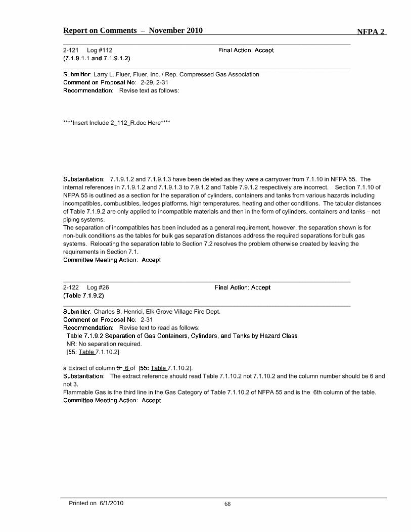
Report on Comments – November 2010 NFPA 2_______________________________________________________________________________________________2-121 Log #112
_______________________________________________________________________________________________Larry L. Fluer, Fluer, Inc. / Rep. Compressed Gas Association
2-29, 2-31Revise text as follows:
****Insert Include 2_112_R.doc Here****
7.1.9.1.2 and 7.1.9.1.3 have been deleted as they were a carryover from 7.1.10 in NFPA 55. Theinternal references in 7.1.9.1.2 and 7.1.9.1.3 to 7.9.1.2 and Table 7.9.1.2 respectively are incorrect. Section 7.1.10 ofNFPA 55 is outlined as a section for the separation of cylinders, containers and tanks from various hazards includingincompatibles, combustibles, ledges platforms, high temperatures, heating and other conditions. The tabular distancesof Table 7.1.9.2 are only applied to incompatible materials and then in the form of cylinders, containers and tanks – notpiping systems.The separation of incompatibles has been included as a general requirement, however, the separation shown is fornon-bulk conditions as the tables for bulk gas separation distances address the required separations for bulk gassystems. Relocating the separation table to Section 7.2 resolves the problem otherwise created by leaving therequirements in Section 7.1.
_______________________________________________________________________________________________2-122 Log #26
_______________________________________________________________________________________________Charles B. Henrici, Elk Grove Village Fire Dept.
2-31Revise text to read as follows:
NR: No separation required.[ Table 7.1.10.2]
a Extract of column 3 6 of [ Table 7.1.10.2].The extract reference should read Table 7.1.10.2 not 7.1.10.2 and the column number should be 6 and
not 3.Flammable Gas is the third line in the Gas Category of Table 7.1.10.2 of NFPA 55 and is the 6th column of the table.
68Printed on 6/1/2010
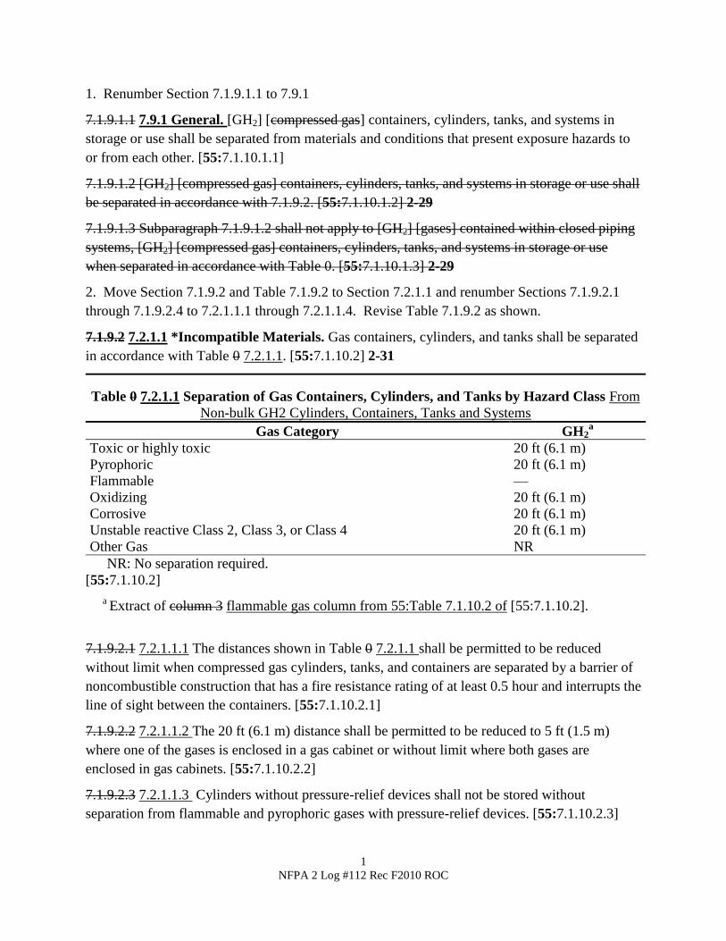
1
NFPA 2 Log #112 Rec F2010 ROC
1. Renumber Section 7.1.9.1.1 to 7.9.1
7.1.9.1.1 7.9.1 General. [GH2] [compressed gas] containers, cylinders, tanks, and systems in
storage or use shall be separated from materials and conditions that present exposure hazards to
or from each other. [55:7.1.10.1.1]
7.1.9.1.2 [GH2] [compressed gas] containers, cylinders, tanks, and systems in storage or use shall
be separated in accordance with 7.1.9.2. [55:7.1.10.1.2] 2-29
7.1.9.1.3 Subparagraph 7.1.9.1.2 shall not apply to [GH2] [gases] contained within closed piping
systems, [GH2] [compressed gas] containers, cylinders, tanks, and systems in storage or use
when separated in accordance with Table 0. [55:7.1.10.1.3] 2-29
2. Move Section 7.1.9.2 and Table 7.1.9.2 to Section 7.2.1.1 and renumber Sections 7.1.9.2.1
through 7.1.9.2.4 to 7.2.1.1.1 through 7.2.1.1.4. Revise Table 7.1.9.2 as shown.
7.1.9.2 7.2.1.1 *Incompatible Materials. Gas containers, cylinders, and tanks shall be separated
in accordance with Table 0 7.2.1.1. [55:7.1.10.2] 2-31
Table 0 7.2.1.1 Separation of Gas Containers, Cylinders, and Tanks by Hazard Class From
Non-bulk GH2 Cylinders, Containers, Tanks and Systems
Gas Category GH2a
Toxic or highly toxic 20 ft (6.1 m)
Pyrophoric 20 ft (6.1 m)
Flammable —
Oxidizing 20 ft (6.1 m)
Corrosive 20 ft (6.1 m)
Unstable reactive Class 2, Class 3, or Class 4 20 ft (6.1 m)
Other Gas NR
NR: No separation required.
[55:7.1.10.2]
a Extract of column 3 flammable gas column from 55:Table 7.1.10.2 of [55:7.1.10.2].
7.1.9.2.1 7.2.1.1.1 The distances shown in Table 0 7.2.1.1 shall be permitted to be reduced
without limit when compressed gas cylinders, tanks, and containers are separated by a barrier of
noncombustible construction that has a fire resistance rating of at least 0.5 hour and interrupts the
line of sight between the containers. [55:7.1.10.2.1]
7.1.9.2.2 7.2.1.1.2 The 20 ft (6.1 m) distance shall be permitted to be reduced to 5 ft (1.5 m)
where one of the gases is enclosed in a gas cabinet or without limit where both gases are
enclosed in gas cabinets. [55:7.1.10.2.2]
7.1.9.2.3 7.2.1.1.3 Cylinders without pressure-relief devices shall not be stored without
separation from flammable and pyrophoric gases with pressure-relief devices. [55:7.1.10.2.3]
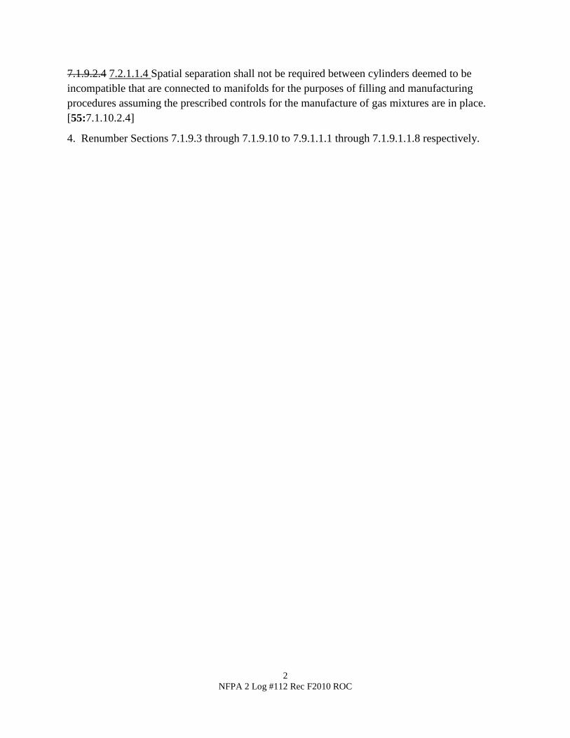
2
NFPA 2 Log #112 Rec F2010 ROC
7.1.9.2.4 7.2.1.1.4 Spatial separation shall not be required between cylinders deemed to be
incompatible that are connected to manifolds for the purposes of filling and manufacturing
procedures assuming the prescribed controls for the manufacture of gas mixtures are in place.
[55:7.1.10.2.4]
4. Renumber Sections 7.1.9.3 through 7.1.9.10 to 7.9.1.1.1 through 7.1.9.1.1.8 respectively.

Report on Comments – November 2010 NFPA 2_______________________________________________________________________________________________2-123 Log #113
_______________________________________________________________________________________________Larry L. Fluer, Fluer, Inc. / Rep. Compressed Gas Association
2-32Revise text to read as follows:
Leaking, damaged, or corroded [GH2] [compressed gas] containers, cylinders, andtanks shall be removed from service. [ 7.1.14.1]
Compressed gas systems in hydrogen service are subject to leakage, however,leakage has not been defined in quantitative terms. Leak rates for outboard leakage sufficient to support stable flameshave been the source of recent study.1 The mass flow rate of hydrogen at its quenching limit has been reported to be3.9 µg/s (0.05 scc/s). Butler, et. al, report that the minimum flow rate necessary for sustaining a hydrogen flame on aleaky 6.3 mm tube compression fitting is 28 µg/s (0.3 scc/s). Leaks below a level sufficient to sustain a hydrogen flamefor systems in the open will diffuse into the atmosphere without consequence. In unventilated spaces, bubble leaks aslow as 0.1 scc/s (8.6 L/day) may warrant repair depending on the natural or mechanical ventilation available to thespace in which the containers are found.1 M.S. Butlera, C.W. Moranb, P.B. Sunderlandb, R.L. Axelbauma,
International Journal of Hydrogen Energy, 34 (2009) 5174-5182.a Department of Energy, Environmental and Chemical Engineering, Washington University, St. Louis, MO 63130, USA.b Department of Fire Protection Engineering, University of Maryland, College Park, MD 20742, USA.
Leaking, damaged, or corroded [GH2] [compressed gas] systems shall bereplaced or repaired. [ 7.1.14.2]
Compressed gas containers,cylinders, and tanks that have been removed from service shall be handled in an approved manner. [ 7.1.14.3]
[GH2] [compressed gas] systems that are determined to be leaking, damaged, or corrodedshall be repaired to a serviceable condition or shall be removed from service. [ 7.1.14.4]
Section 7.1.14.4 is redundant to 7.1.13.2. The only difference is a statement that a repair be madeserviceable which is undefined. An annex note has been added to provide the user with guidance based on recenttesting conducted by researchers at the Department of Energy and the University of Maryland, Department of FireProtection Engineering. The research cited notes that the 2009 Edition of SAE J2579
now limits localized hydrogen leaks inhighway vehicles to a maximum of 5 µg/s (0.06 scc/s)
_______________________________________________________________________________________________2-124 Log #178
_______________________________________________________________________________________________Glenn Mahnken, FM Global
2-1Revise text as follows:
Gas piping in contact with earth or other material that could corrode the piping shall be protected againstcorrosion in an approved manner according to a documented plan and under the supervision of a corrosion expert overthe life of the installation. [ 7.1.17.2]
This change would provide more specific direction for all corrosion protection systems to bedocumented and supervised by a corrosion expert, as is already required for cathodic protection systems.
The committee wants to retain the extract from NFPA 55. The committee believes that thesubstantiation is not strong enough to merit the suggested change.
69Printed on 6/1/2010
Report on Comments – November 2010 NFPA 2_______________________________________________________________________________________________2-125 Log #179
_______________________________________________________________________________________________Glenn Mahnken, FM Global
2-1Add new text as follows:
“As-built” drawings of the underground piping installation shall be maintained on file on the premises.This requirement will help ensure that drawings are on site for response to emergencies or for trouble
shooting.
Revise the suggested new text as follows:“As-built” drawings of the underground piping installation shall be maintained by the owner and shall be
available upon request by the AHJ maintained on file on the premises.The committee agrees with the assertion made by the proponent, but removed the location
requirement for the as-built drawings. The committee felt that the pipeline owner should be required to have thisdocumentation available to an AHJ.
_______________________________________________________________________________________________2-126 Log #27
_______________________________________________________________________________________________Charles B. Henrici, Elk Grove Village Fire Dept.
2-29Revise text to read as follows:
Systems equipped with impressed current cathodic protection systems shallbe inspected in accordance with the requirements of the design and 7.1.18.2. The design limits shall be available to theAHJ upon request.[ 7.1.6.3]
Add the last sentence of Section 7.1.6.3 of NFPA 55 which was omitted. This makes the sectioncomply with the extraction requirements of the Manual of Style.
_______________________________________________________________________________________________2-127 Log #114
_______________________________________________________________________________________________Larry L. Fluer, Fluer, Inc. / Rep. Compressed Gas Association
2-29Revise text to read as follows:
7.1.18.3 Impressed Current Systems. Systems equipped with impressed current cathodic protection systems shall beinspected in accordance with the requirements of the design and 7.1.18.2. The design limits shall be available to theAHJ upon request. [55:7.1.6.3]
The last sentence of the paragraph as extracted from NFPA 55 was missing. NFPA’s extractprocedure asks that the paragraph be extracted in its entirety.
70Printed on 6/1/2010
Report on Comments – November 2010 NFPA 2_______________________________________________________________________________________________2-128 Log #28
_______________________________________________________________________________________________Charles B. Henrici, Elk Grove Village Fire Dept.
2-1Revise text to read as follows:
7.1.18.4 [ ] Repairs, maintenance, or replacement of a cathodic protection system shall be under thesupervision of a NACE certified corrosion expert. [ :7.1.6.4]
Brackets need to be added around "Corrosion Expert" because this was added to the extractedmaterial taken from NFPA 55 to meet the requirements of ROP 2-1.
_______________________________________________________________________________________________2-129 Log #124
_______________________________________________________________________________________________Larry L. Fluer, Fluer, Inc. / Rep. Compressed Gas Association
2-1, 2-35Revise text to read as follows:
Accessible manual valves or automatic remotely activated fail-safe emergency shutoff valves shall beprovided to shut off the GH2 in case of emergency. and clearly marked. [ 7.3.1.11.1]
Emergency shutoff valves on a bulk source or piping systems serving the bulk supply shall be identified bymeans of a sign.
Emergency shutoffs shall be located at the point of use and at the tank, cylinder, or bulk source, [and at thepoint where the system piping enters the building]. [ 7.3.1.11.2]
Accessible manual or automatic emergency shutoff valves shall be provided to shut off the [LH2] [cryogenicfluid] supply in case of emergency. [ :8.14.11.2.3.1]
Emergency shutoff valves on a bulk source or piping systems serving the bulk supply shall be identified bymeans of a sign.
A Emergency shutoff valves shall be located at the point of use, at the source of supply and at the pointwhere the system piping enters the building. [ 8.14.11.2.3.2]
The approach to providing emergency shutoff valves should be consistently applied as generalrequirements of Chapters 7 and 8. The terms “Emergency Shutoff Valve, Manual Emergency Shutoff Valve andAutomatic Emergency Shutoff Valve “ are defined terms. Automatic Emergency Shutoff Valves are required, bydefinition, to be of a fail-safe design. These valve can be activated by either automatic or manual means.
Signage is required for those shutoff systems serving the bulk supply to provide for ready identification. Having ashutoff at each point of use is conventional and the addition of signage is not always appropriate. For example, if theshutoff valve is a cylinder valve the shutoff may be obvious.
71Printed on 6/1/2010

Report on Comments – November 2010 NFPA 2_______________________________________________________________________________________________2-130 Log #115
_______________________________________________________________________________________________Larry L. Fluer, Fluer, Inc. / Rep. Compressed Gas Association
2-301. Revise Section 7.1.22.1 as follows.
7.1.22.1 Where [GH2] is compressed gases or liquids having a hazard ranking of the following in accordance with NFPA704, , are carried inpressurized piping above a gauge pressure of 15 psi (103 kPa), an approved means of leak detection and emergencyshutoff or excess flow control shall be provided: [ 7.3.1.12.1](1) Health hazard Class 3 or Class 4 [ 7.3.1.12.1](2) Flammability Class 4 [ 7.3.1.12.1](3) Reactivity Class 3 or Class 4 [ 7.3.1.12.1]
2. Paragraphs 7.3.1.12.3 and 7.3.1.12.4 were omitted from the printing of the 2010 edition. Erratum have been issuedfor the 2010 Edition of NFPA 55 accordingly. These missing paragraphs are to be restored as shown in the 2005edition. Extract the missing paragraphs into the text of 7.1.22 as follows:
The location of excess flow control shall be as specified in 7.3.1.12.1.1 7.1.22.1.1 and7.3.1.12.1.2 7.1.22.2. [ :7.3.1.12.3]
Where piping originates from a source located in a room or area, the excess flow control shallbe located within the room or area. [ :7.3.1.12.3.1]
Where piping originates from a bulk source, the excess flow control shall be as close to thebulk source as possible. [ :7.3.1.12.3.2]
The requirements of 7.3.1.12 7.1.22.1 shall not apply to the following:(1) Piping for inlet connections designed to prevent backflow(2) Piping for pressure-relief devices(3) Systems containing 450 scf (12.7 m3) or less of [GH2] [flammable gas] [ :7.3.1.12.4]
NFPA 2 has been written for hydrogen. Having requirements for excess flow control that have beendeveloped for other materials is not necessary to include. The text extracted from the 2010 edition of NFPA 55 isincomplete and erratum have been issued. The extract needs to be completed.
Revise the suggested text as follows:1. Revise Section 7.1.22.1 as follows.
7.1.22.1 Where [GH2] is compressed gases or liquids having a hazard ranking of the following in accordance with NFPA704, , are carried inpressurized piping above a gauge pressure of 15 psi (103 kPa), an approved means of leak detection and emergencyshutoff or excess flow control shall be provided. [ 7.3.1.12.1](1) Health hazard Class 3 or Class 4 [ 7.3.1.12.1](2) Flammability Class 4 [ 7.3.1.12.1](3) Reactivity Class 3 or Class 4 [ 7.3.1.12.1]
2. Paragraphs 7.3.1.12.3 and 7.3.1.12.4 were omitted from the printing of the 2010 edition. Erratum have been issuedfor the 2010 Edition of NFPA 55 accordingly. These missing paragraphs are to be restored as shown in the 2005edition. Extract the missing paragraphs into the text of 7.1.22 as follows:
The location of excess flow control shall be as specified in 7.3.1.12.1.1 7.1.22.1.1 and7.3.1.12.1.2 7.1.22.2. [ :7.3.1.12.3]
Where piping originates from a source located in a room or area, the excess flow control shallbe located within the room or area. [ :7.3.1.12.3.1]
Where piping originates from a bulk source, the excess flow control shall be as close to thebulk source as possible. [ :7.3.1.12.3.2]
The requirements of 7.3.1.12 7.1.22.1 shall not apply to the following:(1) Piping for inlet connections designed to prevent backflow(2) Piping for pressure-relief devices(3) Systems containing 400450 scf (12.7 m3) or less of [GH2] [flammable gas] [ :7.3.1.12.4]
The committee modified the quantity from NFPA 55 Section 7.1.22.1.4(3), which was applicable
72Printed on 6/1/2010
Report on Comments – November 2010 NFPA 2to all flammable gases in order to be specific to hydrogen.
_______________________________________________________________________________________________2-131 Log #261
_______________________________________________________________________________________________Christopher Radley, Altergy Systems
2-1Delete this paragraph or revise due to inconsistencies.
The definition of Non-Bulk GH2 is lower than the quantities set in the applicability definition of thischapter. Therefore, this requirement in inconsistent. Also, the referenced table should be Table 6.4.1.1.
The proponent submitted a series of comments related to the subject, which the committeebelieves confused bulk vs. non-bulk conditions per 7.2.2.1.1. A new definition and annex note are being created toimprove clarity surrounding the issues raised by the proponent [See 2-144 (Log #255)].
_______________________________________________________________________________________________2-132 Log #119
_______________________________________________________________________________________________Larry L. Fluer, Fluer, Inc. / Rep. Compressed Gas Association
2-29Add text to read as follows:
7.2.2.2.1 Indoor GH2 systems in control areas with less than the Maximum Allowable Quantities per Control Areashown in Table 6.4.1.1 shall be located in accordance with the applicable provisions of Table 7.3.2.2.1.
Table 7.3.2.2.1 is found in the bulk section. Hydrogen storage systems with quantities less than MAQare governed by Table 7.3.2.2.1. The alternative is to restructure 7.1 and relocate Table 7.3.2.2.1. The simpler fix forthis edition of NFPA 2 is to add Section 7.2.2.2.1 to alert the user accordingly.
_______________________________________________________________________________________________2-133 Log #117
_______________________________________________________________________________________________Larry L. Fluer, Fluer, Inc. / Rep. Compressed Gas Association
2-1Revise text to read as follows:
The outdoor storage or use of [GH2] [flammable compressed gas] shall be locatedfrom lot lines, public streets, public alleys, public ways, [exit discharges,] or buildings not associated with themanufacture or distribution of [GH2] [such gases] in accordance with Table 7.2.2.3.2. [ 7.6.2]
The term “exit discharge” has been added to the extract text. This creates confusion when one refersto 7.2.2.3.2.3 which regulates proximity to building openings. An exit discharge is the exterior exit door in a building andthe provisions of 7.2.2.3.2.3 would apply. In addition, building exits are not one of the items in the table, therefore theuser is referred to a table for distances where none exist. Deletion of the added text will resolve the problem.
73Printed on 6/1/2010

Report on Comments – November 2010 NFPA 2_______________________________________________________________________________________________2-134 Log #116
_______________________________________________________________________________________________Larry L. Fluer, Fluer, Inc. / Rep. Compressed Gas Association
2-1Delete Table 7.2.2.3.2 as shown and replace it with Table 7.6.2 to be extracted from NFPA 55
2010 Edition
The 2010 Edition of NFPA 55 is the proper source document. The table title as shown in NFPA 55 iscorrect as the table applies to Non-bulk hydrogen in the gaseous form. There is a maximum quantity in a non-bulk(typically loose cylinders) storage area of 200,000 cubic feet. Additional quantities require either separation by distanceor barrier.
_______________________________________________________________________________________________2-135 Log #260
_______________________________________________________________________________________________Christopher Radley, Altergy Systems
2-1Delete this Table or revise due to inconsistencies.
Table is inconsistent with the definition of non-bulk storage thresholds and it contradicts the setbackstated in 7.3.2.3.1.1 and its subparagraphs.
The table is designed for non-bulk [See 2-134 (Log #116)]. The new definition in 2-144 (Log#255) will also address the concerns of the submitter.
_______________________________________________________________________________________________2-136 Log #29
_______________________________________________________________________________________________Charles B. Henrici, Elk Grove Village Fire Dept.
2-1Revise text to read as follows:
Storage and use of [GH2] [flammable compressed gases] shall not be located within 50 ft(15.2 m) of air intakes. [ 7.6.2.4]
Brackets need to be added around “Air Intakes” because this was added to the extracted material fromNFPA 55.
74Printed on 6/1/2010
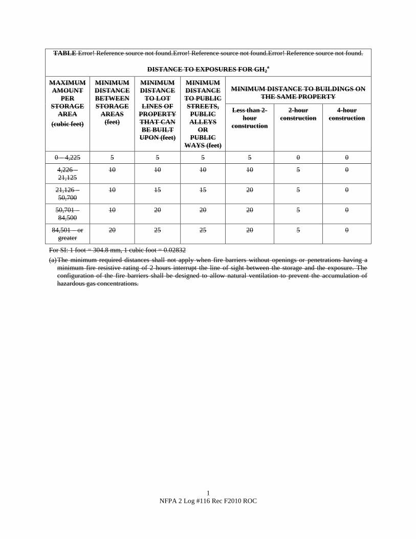
1
NFPA 2 Log #116 Rec F2010 ROC
TABLE Error! Reference source not found.Error! Reference source not found.Error! Reference source not found.
DISTANCE TO EXPOSURES FOR GH2a
MAXIMUM
AMOUNT
PER
STORAGE
AREA
(cubic feet)
MINIMUM
DISTANCE
BETWEEN
STORAGE
AREAS
(feet)
MINIMUM
DISTANCE
TO LOT
LINES OF
PROPERTY
THAT CAN
BE BUILT
UPON (feet)
MINIMUM
DISTANCE
TO PUBLIC
STREETS,
PUBLIC
ALLEYS
OR
PUBLIC
WAYS (feet)
MINIMUM DISTANCE TO BUILDINGS ON
THE SAME PROPERTY
Less than 2-
hour
construction
2-hour
construction
4-hour
construction
0 – 4,225 5 5 5 5 0 0
4,226 –
21,125
10 10 10 10 5 0
21,126 –
50,700
10 15 15 20 5 0
50,701 –
84,500
10 20 20 20 5 0
84,501 – or
greater
20 25 25 20 5 0
For SI: 1 foot = 304.8 mm, 1 cubic foot = 0.02832
(a) The minimum required distances shall not apply when fire barriers without openings or penetrations having a
minimum fire resistive rating of 2 hours interrupt the line of sight between the storage and the exposure. The
configuration of the fire barriers shall be designed to allow natural ventilation to prevent the accumulation of
hazardous gas concentrations.
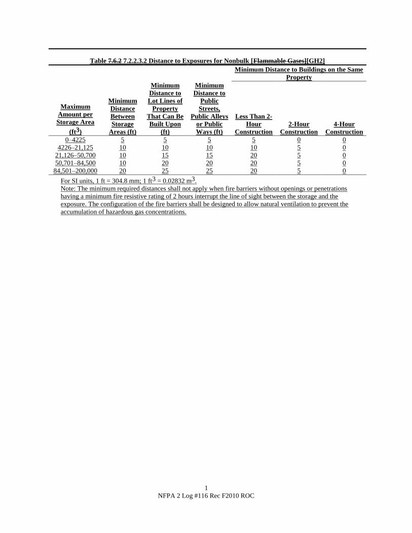
1
NFPA 2 Log #116 Rec F2010 ROC
Table 7.6.2 7.2.2.3.2 Distance to Exposures for Nonbulk [Flammable Gases][GH2]
Minimum Distance to Buildings on the Same
Property
Maximum
Amount per
Storage Area
(ft3)
Minimum
Distance
Between
Storage
Areas (ft)
Minimum
Distance to
Lot Lines of
Property
That Can Be
Built Upon
(ft)
Minimum
Distance to
Public
Streets,
Public Alleys
or Public
Ways (ft)
Less Than 2-
Hour
Construction
2-Hour
Construction
4-Hour
Construction
0–4225 5 5 5 5 0 0
4226–21,125 10 10 10 10 5 0
21,126–50,700 10 15 15 20 5 0
50,701–84,500 10 20 20 20 5 0
84,501–200,000 20 25 25 20 5 0
For SI units, 1 ft = 304.8 mm; 1 ft3 = 0.02832 m3.
Note: The minimum required distances shall not apply when fire barriers without openings or penetrations
having a minimum fire resistive rating of 2 hours interrupt the line of sight between the storage and the
exposure. The configuration of the fire barriers shall be designed to allow natural ventilation to prevent the
accumulation of hazardous gas concentrations.
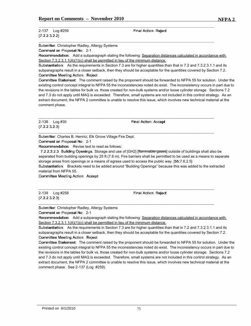
Report on Comments – November 2010 NFPA 2_______________________________________________________________________________________________2-137 Log #259
_______________________________________________________________________________________________Christopher Radley, Altergy Systems
2-1Add a subparagraph stating the following: Separation distances calculated in accordance with
Section 7.3.2.3.1.1(A)(1)(c) shall be permitted in lieu of the minimum distance.As the requirements in Section 7.3 are for higher quantities than that in 7.2 and 7.3.2.3.1.1 and its
subparagraphs result in a closer setback, then they should be acceptable for the quantities covered by Section 7.2.
The comment raised by the proponent should be forwarded to NFPA 55 for solution. Under theexisting control concept integral to NFPA 55 the inconsistencies noted do exist. The inconsistency occurs in part due tothe revisions in the tables for bulk vs. those created for non-bulk systems and/or loose cylinder storage. Sections 7.2and 7.3 do not apply until MAQ is exceeded. Therefore, small systems are not included in this control strategy. As anextract document, the NFPA 2 committee is unable to resolve this issue, which involves new technical material at thecomment phase.
_______________________________________________________________________________________________2-138 Log #30
_______________________________________________________________________________________________Charles B. Henrici, Elk Grove Village Fire Dept.
2-1Revise text to read as follows:
Storage and use of [GH2] [flammable gases] outside of buildings shall also beseparated from building openings by 25 ft (7.6 m). Fire barriers shall be permitted to be used as a means to separatestorage areas from openings or a means of egress used to access the public way. [ 7.6.2.5]
Brackets need to be added around “Building Openings” because this was added to the extractedmaterial from NFPA 55.
_______________________________________________________________________________________________2-139 Log #258
_______________________________________________________________________________________________Christopher Radley, Altergy Systems
2-1Add a subparagraph stating the following: Separation distances calculated in accordance with
Section 7.3.2.3.1.1(A)(1)(c) shall be permitted in lieu of the minimum distance.As the requirements in Section 7.3 are for higher quantities than that in 7.2 and 7.3.2.3.1.1 and its
subparagraphs result in a closer setback, then they should be acceptable for the quantities covered by Section 7.2.
The comment raised by the proponent should be forwarded to NFPA 55 for solution. Under theexisting control concept integral to NFPA 55 the inconsistencies noted do exist. The inconsistency occurs in part due tothe revisions in the tables for bulk vs. those created for non-bulk systems and/or loose cylinder storage. Sections 7.2and 7.3 do not apply until MAQ is exceeded. Therefore, small systems are not included in this control strategy. As anextract document, the NFPA 2 committee is unable to resolve this issue, which involves new technical material at thecomment phase. See 2-137 (Log #259).
75Printed on 6/1/2010
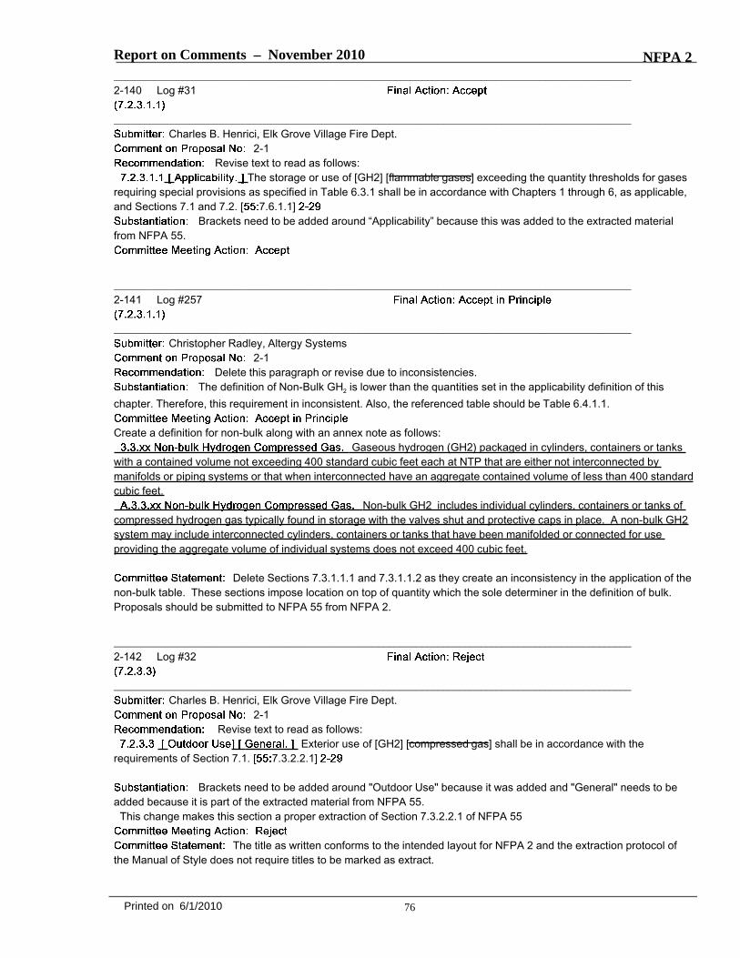
Report on Comments – November 2010 NFPA 2_______________________________________________________________________________________________2-140 Log #31
_______________________________________________________________________________________________Charles B. Henrici, Elk Grove Village Fire Dept.
2-1Revise text to read as follows:
The storage or use of [GH2] [flammable gases] exceeding the quantity thresholds for gasesrequiring special provisions as specified in Table 6.3.1 shall be in accordance with Chapters 1 through 6, as applicable,and Sections 7.1 and 7.2. [ 7.6.1.1]
Brackets need to be added around “Applicability” because this was added to the extracted materialfrom NFPA 55.
_______________________________________________________________________________________________2-141 Log #257
_______________________________________________________________________________________________Christopher Radley, Altergy Systems
2-1Delete this paragraph or revise due to inconsistencies.
The definition of Non-Bulk GH2 is lower than the quantities set in the applicability definition of thischapter. Therefore, this requirement in inconsistent. Also, the referenced table should be Table 6.4.1.1.
Create a definition for non-bulk along with an annex note as follows:Gaseous hydrogen (GH2) packaged in cylinders, containers or tanks
with a contained volume not exceeding 400 standard cubic feet each at NTP that are either not interconnected bymanifolds or piping systems or that when interconnected have an aggregate contained volume of less than 400 standardcubic feet.
Non-bulk GH2 includes individual cylinders, containers or tanks ofcompressed hydrogen gas typically found in storage with the valves shut and protective caps in place. A non-bulk GH2system may include interconnected cylinders, containers or tanks that have been manifolded or connected for useproviding the aggregate volume of individual systems does not exceed 400 cubic feet.
Delete Sections 7.3.1.1.1 and 7.3.1.1.2 as they create an inconsistency in the application of thenon-bulk table. These sections impose location on top of quantity which the sole determiner in the definition of bulk.Proposals should be submitted to NFPA 55 from NFPA 2.
_______________________________________________________________________________________________2-142 Log #32
_______________________________________________________________________________________________Charles B. Henrici, Elk Grove Village Fire Dept.
2-1Revise text to read as follows:
Exterior use of [GH2] [compressed gas] shall be in accordance with therequirements of Section 7.1. [ 7.3.2.2.1]
Brackets need to be added around "Outdoor Use" because it was added and "General" needs to beadded because it is part of the extracted material from NFPA 55.
This change makes this section a proper extraction of Section 7.3.2.2.1 of NFPA 55
The title as written conforms to the intended layout for NFPA 2 and the extraction protocol ofthe Manual of Style does not require titles to be marked as extract.
76Printed on 6/1/2010

Report on Comments – November 2010 NFPA 2_______________________________________________________________________________________________2-143 Log #256
_______________________________________________________________________________________________Christopher Radley, Altergy Systems
2-1Exterior use of GH2 shall be in accordance with the requirements of Section 7.1, where applicable.
As most of the requirements in Section 7.1 pertain to building related requirements, most of therequirements are not applicable to outdoor installations.
Revise the submitted text as follows:Exterior use of GH2 shall be in accordance with the applicable requirements of with the requirements of Section 7.1,
where applicable.The committee agreed with the proponent and restructured the comment with respect to form.
_______________________________________________________________________________________________2-144 Log #255
_______________________________________________________________________________________________Christopher Radley, Altergy Systems
2-1Delete this paragraph or revise due to inconsistencies.
The definition of Non-Bulk GH2 is lower than the quantities set in the applicability definition of thischapter. Therefore, this requirement in inconsistent. Also, the referenced table should be Table 6.4.1.1.
See the committee action taken on 2-141 (Log #257), which covers the same subject. Theaddition of definition for non-bulk and deletions of paragraphs 7.3.1.1.1 and 7.3.1.1.2 addresses the concern.
_______________________________________________________________________________________________2-145 Log #33
_______________________________________________________________________________________________Charles B. Henrici, Elk Grove Village Fire Dept.
2-1Revise text to read as follows:
[Section 7.3] [This chapter] shall not apply to individual systems using containers having a total hydrogencontent of less than 400 scf (11 m3) if each system is separated by a distance not less than 5 ft (1.5 m). [ 10.1.2.1]
Adding the brackets and the omitted wording from NFPA 55 makes this section a proper extractionfrom NFPA 55.
_______________________________________________________________________________________________2-146 Log #34
_______________________________________________________________________________________________Charles B. Henrici, Elk Grove Village Fire Dept.
2-1, 2-29Revise text to read as follows:
Fire protection shall be in accordance with the requirements of Section 6. 9. 10 [ 10.6]
The proper Section in NFPA 2 is 6.10.
77Printed on 6/1/2010
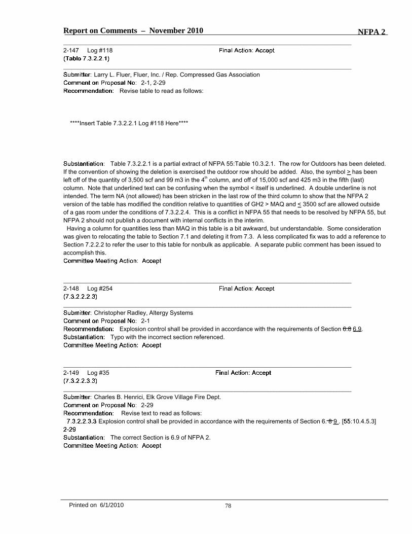
Report on Comments – November 2010 NFPA 2_______________________________________________________________________________________________2-147 Log #118
_______________________________________________________________________________________________Larry L. Fluer, Fluer, Inc. / Rep. Compressed Gas Association
2-1, 2-29Revise table to read as follows:
****Insert Table 7.3.2.2.1 Log #118 Here****
Table 7.3.2.2.1 is a partial extract of NFPA 55:Table 10.3.2.1. The row for Outdoors has been deleted.If the convention of showing the deletion is exercised the outdoor row should be added. Also, the symbol > has beenleft off of the quantity of 3,500 scf and 99 m3 in the 4th column, and off of 15,000 scf and 425 m3 in the fifth (last)column. Note that underlined text can be confusing when the symbol < itself is underlined. A double underline is notintended. The term NA (not allowed) has been stricken in the last row of the third column to show that the NFPA 2version of the table has modified the condition relative to quantities of GH2 > MAQ and < 3500 scf are allowed outsideof a gas room under the conditions of 7.3.2.2.4. This is a conflict in NFPA 55 that needs to be resolved by NFPA 55, butNFPA 2 should not publish a document with internal conflicts in the interim.
Having a column for quantities less than MAQ in this table is a bit awkward, but understandable. Some considerationwas given to relocating the table to Section 7.1 and deleting it from 7.3. A less complicated fix was to add a reference toSection 7.2.2.2 to refer the user to this table for nonbulk as applicable. A separate public comment has been issued toaccomplish this.
_______________________________________________________________________________________________2-148 Log #254
_______________________________________________________________________________________________Christopher Radley, Altergy Systems
2-1Explosion control shall be provided in accordance with the requirements of Section 6.8 6.9.
Typo with the incorrect section referenced.
_______________________________________________________________________________________________2-149 Log #35
_______________________________________________________________________________________________Charles B. Henrici, Elk Grove Village Fire Dept.
2-29Revise text to read as follows:
Explosion control shall be provided in accordance with the requirements of Section 6. 8 9 . [ 10.4.5.3]
The correct Section is 6.9 of NFPA 2.
78Printed on 6/1/2010
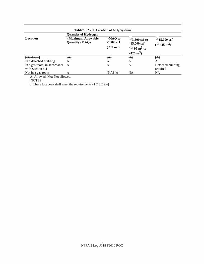
1
NFPA 2 Log #118 F2010 ROC
Table7.3.2.2.1 Location of GH2 Systems
Quantity of Hydrogen
Location <Maximum Allowable
Quantity (MAQ)
>MAQ to
<3500 scf
(<99 m3)
3,500 scf to
<15,000 scf
( 99 m3 to
<425 m3)
15,000 scf
( 425 m3)
[Outdoors] [A] [A] [A] [A]
In a detached building A A A A
In a gas room, in accordance
with Section 6.4
A A A Detached building
required
Not in a gas room A [NA] [A1] NA NA
A: Allowed. NA: Not allowed.
[NOTES:]
[ 1 These locations shall meet the requirements of 7.3.2.2.4]

Report on Comments – November 2010 NFPA 2_______________________________________________________________________________________________2-150 Log #253
_______________________________________________________________________________________________Christopher Radley, Altergy Systems
2-1Explosion control shall be provided in accordance with the requirements of Section 6.8 6.9.
Typo with the incorrect section referenced.
_______________________________________________________________________________________________2-151 Log #36
_______________________________________________________________________________________________Charles B. Henrici, Elk Grove Village Fire Dept.
2-29, 2-30Revise text to read as follows:
(1) In a ventilated area in accordance with the provisions of Section 6. 15 17 [ 10.4.6.1]The correct Section is 6.17 of NFPA 2.
_______________________________________________________________________________________________2-152 Log #252
_______________________________________________________________________________________________Christopher Radley, Altergy Systems
2-1In a ventilated area in accordance with the provisions of Section 6.15 6.17.
Typo with the incorrect section referenced.
_______________________________________________________________________________________________2-153 Log #38
_______________________________________________________________________________________________Charles B. Henrici, Elk Grove Village Fire Dept.
2-29Revise text to read as follows:
The separation distance between multiple systems of 3500 scf (99 m3) or less shall be permitted to be reduced to25 ft (7.6 m) in buildings where the space between storage areas is free of combustible materials and protected with asprinkler system designed for Extra Hazard, Group 1 in accordance with the requirements of Section 6. 9 10 .[ 10.4.6.2.2]
The correct Section is 6.10 of NFPA 2
79Printed on 6/1/2010
Report on Comments – November 2010 NFPA 2_______________________________________________________________________________________________2-154 Log #250
_______________________________________________________________________________________________Christopher Radley, Altergy Systems
2-1Delete Item 10 in the Tables.
Currently, public transportation and fuel cell vehicles store hydrogen in the quantities and pressurescovered by these tables. They are not required to maintain a setback distance from other parked cars in parking lots norare they required to maintain a set distance from other vehicles on the road. As such, the stationary installations arebeing held to a higher level than the car it may have to stay away from. This requirement may make sense for largerquantities of stored hydrogen and as such, the threshold for the definition of bulk storage should be re-evaluated.Another option would be to reduce the setback to 0 ft if a non-combustible barrier is used in accordance with Section7.1.9.3.1 and 7.1.9.3.2.
Exposure to people has already been addressed as a concern, which is indicated by footnote e.
_______________________________________________________________________________________________2-155 Log #251
_______________________________________________________________________________________________Christopher Radley, Altergy Systems
2-1Delete Item 2 in the Tables.
This requirement was derived from the IFC Table 2209.5.4.3.4 and is for vent and purge pipe systems.As the systems defined in these Tables are for closed systems (as defined by the electrical requirements), then therequirements should not carry over. There are millions of propane tanks at residential and commercial locations that arenot blocked off with a setback preventing someone from the public from walking next to it. It is not reasonable to requirethis on hydrogen systems over 400 SCF. There may be an SCF level in which this would make sense, but it needs to beremembered that the energy density of 400 SCF is only equivalent to that of 1 gallon of gasoline. This requirementessentially removes the possibility for installing hydrogen storage above 400 scf at any residential location and there isno reasonable safety reason to do so.
It should also be considered that public adults and children are within these setbacks of compressed hydrogen andCNG systems every day when they ride on public transportation powered by these fuels or are in fuel cell or CNGvehicles.
The release of a gas with an opening of 3% area will also make a significant audible warning to people present oneither property. A test was performed at Altergy using 3/8” tubing (0.277” ID) with a 0.050” hole pressurized to 1600 psi.No self-ignition occurred and an audible signature of 126 dBA was measured from 10 ft away. It should be mentionedthat a jackhammer from 10 feet away measures 100-110 dB. Therefore, there would be an audible alarm and asufficient time for a person to move to a safe location of to isolate the leak.
For small systems, the quantity released is low enough and the concentration dissipates quick enough that a personbeing overcome due to asphyxiation.
The exposure value of 1,500 Btu/hr-ft2 is defined by API 521 as the heat flux threshold in areaswhere emergency actions lasting several minutes may be required by personnel without shielding with appropriateclothing. The note is included in Annex I.5(2).
The use of an audible warning produced by a leak as a means to warn an individual is not suitable as a means to offsetdistance requirements.
80Printed on 6/1/2010

Report on Comments – November 2010 NFPA 2_______________________________________________________________________________________________2-156 Log #269
_______________________________________________________________________________________________Christopher Radley, Altergy Systems
2-1Add a subparagraph stating the following: Lot line separation distances may be reduced by 5 ft (1.5
m) if a noncombustible partition is used in accordance with Sections 7.1.9.3.1 and 7.1.9.3.2.The setback distances from lot lines are based on either an unignited jet concentration decay distance
of 4% mole fraction (volume fraction) of hydrogen or a Drad radiation level of 500 BTU/hr ft2. A non-combustible partitionin accordance with Sections 7.1.9.3.1 and 7.1.9.3.2 would act as a barrier to deflect the impingement of an unignitedplume and would provide protection similar to that shown in NFPA 497 for indoor hydrogen systems in which the areaoutside below the level of the partition is an unclassified area. This would make sense as hydrogen is 14x lighter than airand will dissipate quickly. In addition, requiring the partition to be within 18” of the storage system would require preventany ignition sources to be present to reduce the possibility of ignition. Should it ignite, the noncombustible partitionwould create a temporary flame impingement barrier on adjoining lots.
The release of a gas with an opening of 3% area will also make a significant audible warning to people present oneither property. A test was performed at Altergy using 3/8” tubing (0.277” ID) with a 0.050” hole pressurized to 1600 psi.No self-ignition occurred and a audible signature of 126 dBA was measured from 10 ft away. It should be mentioned thata jackhammer from 10 feet away measures 100-110 dB. Therefore, there would be an audible alarm and a sufficienttime for an emergency response to either isolate the leak or to protect exposures.
The methods should be an acceptable design mitigation to lower the lot line setback by 5 ft as it represents half theamount allowed in Section 7.1.9.3 from combustible vegetation.
The proponent seeks a reduction in the separation distance to lot lines if a barrier is used. Areduction in the distance through the use of fire barriers is already the function of 7.3.2.3.1.1(C), where the distance canbe reduced by half.
_______________________________________________________________________________________________2-157 Log #64
_______________________________________________________________________________________________Christopher Radley, Altergy Systems
2-1Revise text as follows:
The greater of Drad for combustible heat flux level of 6340 BTU/hr ft2 [20,000 W/m2] or visible flame length. Drad –Radiation Heat Flux Level of 6340 BTU/hr ft2 [20,000 W/m2].
The fact that a flame tip is visible in the visible light spectrum does not change the thermal effect of thecombusting gasses. Therefore, the variable that is of concern is the heat flux level at a given point regardless of thecolor or visibility of the flame. Based on this, the setback should not be based on a visible flame length if the heat flux atthat point is below the level of criticality.
The original research confirms the tabular values. In some cases the visible flame lengthexceed D(rad) and in other cases D(rad) dominates. The footnotes are included in the table for valuable informationalpurposes.
● The visible flame lengths have been measured by Sandia National Lab in detailed work cited in Annex E.● Sandia technical personnel confirm that in some instances flame length exceeds D(rad) and in other cases the
reverse is true.The committee defers to the substantiation made in Annex E.
81Printed on 6/1/2010

Report on Comments – November 2010 NFPA 2_______________________________________________________________________________________________2-158 Log #57
_______________________________________________________________________________________________Christopher Radley, Altergy Systems
2-1Revise text as follows:
The greater of Drad for combustible heat flux level of 8000 BTU/hr ft2 [25,237 W/m2] or visible flame length. Drad –Radiation Heat Flux Level of 8000 BTU/hr ft2 [25,237 W/m2].
The fact that a flame tip is visible in the visible light spectrum does not change the thermal effect of thecombusting gasses. Therefore, the variable that is of concern is the heat flux level at a given point regardless of thecolor or visibility of the flame. Based on this, the setback should not be based on a visible flame length if the heat flux atthat point is below the level of criticality.
The original research confirms the tabular values. In some cases the visible flame lengthexceed D(rad) and in other cases D(rad) dominates. The footnotes are included in the table for valuable informationalpurposes.
● The visible flame lengths have been measured by Sandia National Lab in detailed work cited in Annex E.● Sandia technical personnel confirm that in some instances flame length exceeds D(rad) and in other cases the
reverse is true.The committee defers to the substantiation made in Annex E.
_______________________________________________________________________________________________2-159 Log #58
_______________________________________________________________________________________________Christopher Radley, Altergy Systems
2-1Delete footnote f and any setbacks based on it.
A required setback should not be imposed by the standard on an assumption that access is requiredfor service related activities. At the minimum, it should be deleted and a paragraph added that sufficient clearance bemaintained around a system to allow adequate required access for service related activities.
This is a developmental issue that the committee believes should be brought to the NFPA 55committee rather than to the NFPA 2 committee at the comment phase. A proposal should be issued to NFPA 55 toaddress wall mounted equipment.
_______________________________________________________________________________________________2-160 Log #59
_______________________________________________________________________________________________Christopher Radley, Altergy Systems
2-1Simplify equations using a maximum of 3 significant digits for all coefficients and exponents.
Round to 1 where 3 significant digits are 0.999.Based on rounding to the nearest 5 feet, the use of more than 3 significant figures is unnecessary and
may lead to calculation errors.
This is a developmental issue that the committee believes should be brought to the NFPA 55committee rather than to the NFPA 2 committee at the comment phase. A proposal should be issued to NFPA 55 toaddress wall mounted equipment. The annex provides guidance to the user to calculate distances using the alternativemethod system.
82Printed on 6/1/2010
Report on Comments – November 2010 NFPA 2_______________________________________________________________________________________________2-161 Log #60
_______________________________________________________________________________________________Christopher Radley, Altergy Systems
2-1Re-derive the equations in English units.
As the end calculation is in English units and the most probable starting value will be in English units,requiring the user to convert to and then from SI units only causes confusion and could lead to calculation errors.
This is a developmental issue that the committee believes should be brought to the NFPA 55committee rather than to the NFPA 2 committee at the comment phase. A proposal should be issued to NFPA 55 toaddress wall mounted equipment. The annex provides guidance to the user to calculate distances using the alternativemethod system.
_______________________________________________________________________________________________2-162 Log #61
_______________________________________________________________________________________________Christopher Radley, Altergy Systems
2-1Delete paragraph.
The requirements for a fire wall based on a heavier-than-air cryogenic liquid should not be the samefor a lighter-than-air gas. It should be permissible to install a gaseous hydrogen storage system in a court of four firerated walls, if desired, provided that the area above the court is open to allow natural ventilation to prevent theaccumulation of hazardous gas concentrations as discussed in Table 7.2.2.3.2 footnote (a).
The proponent suggests to install bulk GH2 systems in a court, provided the court is not anatrium.
● The proponent states that the requirement for open space is based on cryogenic fluids. This was not intended.● In 2-159 (Log #58) the proponent proposed to eliminate service clearance, therefore the system could be installed in
a confined space.● The installation visualized could be inside of any building that had a hole in the roof. A court could be of unlimited
height.●Minimum ventilation is not specified nor has it been considered other than to claim that open to the sky is sufficient as
a means to ventilate the space.● Confinement in any space can amplify the effects of an explosion should explosion or even fast deflagration occur.The requirement is extract text and if a change is desired a proposal should be sent to NFPA 55.
_______________________________________________________________________________________________2-163 Log #37
_______________________________________________________________________________________________Charles B. Henrici, Elk Grove Village Fire Dept.
2-29Revise text to read as follows:
Where overhead cover is provided, it shall be in accordance with the provisions of 6. 5.1 6 . [ 10.4.1.1]The correct Section number is 6.6 in NFPA 2
83Printed on 6/1/2010
Report on Comments – November 2010 NFPA 2_______________________________________________________________________________________________2-164 Log #62
_______________________________________________________________________________________________Christopher Radley, Altergy Systems
2-1Revise text to read as follows:
Where overhead cover is provided, it shall be in accordance with the provisions of 6.5.1 6.6.Typo pointing to the incorrect section.
_______________________________________________________________________________________________2-165 Log #39
_______________________________________________________________________________________________Charles B. Henrici, Elk Grove Village Fire Dept.
2-29Revise text to read as follows:
Vehicular protection shall be provided in accordance with 7.1.7.3.3 4.15.1.1 . [ 10.4.1.3]The correct Section number should be 4.15.1.1 of NFPA 2. Section 7.1.7.3.3 refers you back to
4.15.1.1. The Code should be direct in its references. This change makes it easier for the AHJ to use the code.The code should not be written in a format that refers you to a section that refers you to another section.
Revise the submitted text to read as follows:Vehicular protection shall be provided in accordance with 7.1.7.3.3 4.15.1.1. [ 10.4.1.3]
The committee believes that the entire section should be followed without jumping to 4.15.1.1.
_______________________________________________________________________________________________2-166 Log #40
_______________________________________________________________________________________________Charles B. Henrici, Elk Grove Village Fire Dept.
2-29Revise text to read as follows:
[GH2] [Compressed gas] containers and underground piping shall be protected fromcorrosion in accordance with 7.1.9.9, 7.1.14 or and 7.1.15.3 as applicable. [ 10.4.2.2]
I believe Section 7.1.14 should be added to this section because all three of the sections referenceddeal with corrosion.
84Printed on 6/1/2010

Report on Comments – November 2010 NFPA 2_______________________________________________________________________________________________2-167 Log #63
_______________________________________________________________________________________________Christopher Radley, Altergy Systems
2-1Add a subparagraph stating: Separation distances may be reduced to those defined in Table
10.3.2.3.1.3 if an SAE J2600 nozzle is used on the unloading connection.If an SAE J2600 nozzle is used to perform the cargo transport unloading, then the process is very
similar to that defined in Sections 10.3.2.3, 10.3.3.3.5 and their subparagraphs. In addition, NFPA 58 Table 6.5.3 andSections 6.5.4.4 and 6.26.5 allow closer setbacks for a heavier-than-air flammable gas. This table and requirementscould be used in conjunction with those of Table 10.3.2.3.1.3, if required, to replace the current setbacks specified in7.3.4.2.1.
The controls on fuel dispensers are substantially different from those on transport vehicles.The suggested approach is a developmental approach that would best be considered during the proposal phase. Thereis merit to the concept, but the TC feels that it should be considered within the context of the mitigation tables under thepurview of Task Group 6 and in conjunction with the NFPA 55 TC.
85Printed on 6/1/2010
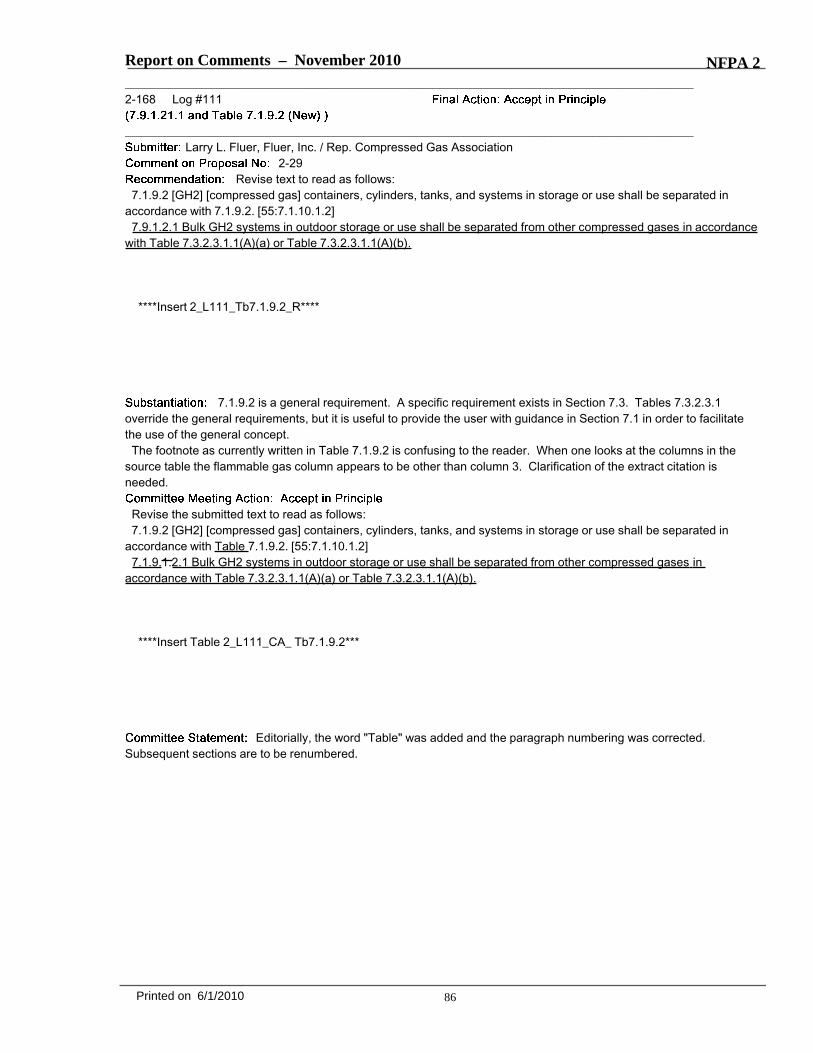
Report on Comments – November 2010 NFPA 2_______________________________________________________________________________________________2-168 Log #111
_______________________________________________________________________________________________Larry L. Fluer, Fluer, Inc. / Rep. Compressed Gas Association
2-29Revise text to read as follows:
7.1.9.2 [GH2] [compressed gas] containers, cylinders, tanks, and systems in storage or use shall be separated inaccordance with 7.1.9.2. [55:7.1.10.1.2]
7.9.1.2.1 Bulk GH2 systems in outdoor storage or use shall be separated from other compressed gases in accordancewith Table 7.3.2.3.1.1(A)(a) or Table 7.3.2.3.1.1(A)(b).
****Insert 2_L111_Tb7.1.9.2_R****
7.1.9.2 is a general requirement. A specific requirement exists in Section 7.3. Tables 7.3.2.3.1override the general requirements, but it is useful to provide the user with guidance in Section 7.1 in order to facilitatethe use of the general concept.
The footnote as currently written in Table 7.1.9.2 is confusing to the reader. When one looks at the columns in thesource table the flammable gas column appears to be other than column 3. Clarification of the extract citation isneeded.
Revise the submitted text to read as follows:7.1.9.2 [GH2] [compressed gas] containers, cylinders, tanks, and systems in storage or use shall be separated in
accordance with Table 7.1.9.2. [55:7.1.10.1.2]7.1.9.1.2.1 Bulk GH2 systems in outdoor storage or use shall be separated from other compressed gases in
accordance with Table 7.3.2.3.1.1(A)(a) or Table 7.3.2.3.1.1(A)(b).
****Insert Table 2_L111_CA_ Tb7.1.9.2***
Editorially, the word "Table" was added and the paragraph numbering was corrected.Subsequent sections are to be renumbered.
86Printed on 6/1/2010
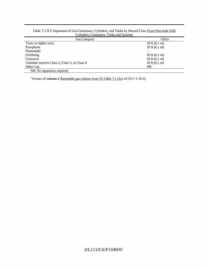
2/L111/CA/F10/ROC
Table 7.1.9.2 Separation of Gas Containers, Cylinders, and Tanks by Hazard Class From Non-bulk GH2
Cylinders, Containers, Tanks and Systems
Gas Category GH2a
Toxic or highly toxic 20 ft (6.1 m)
Pyrophoric 20 ft (6.1 m)
Flammable —
Oxidizing 20 ft (6.1 m)
Corrosive 20 ft (6.1 m)
Unstable reactive Class 2, Class 3, or Class 4 20 ft (6.1 m)
Other Gas NR
NR: No separation required.
a Extract of column 3 flammable gas column from 55:Table 7.1.10.2 of [55:7.1.10.2].

Report on Comments – November 2010 NFPA 2_______________________________________________________________________________________________2-169 Log #41
_______________________________________________________________________________________________Stephen Woods, NASA White Sands Test Facility
255-1Revise text to read as follows:
Portable containers that are open to the atmosphere and are designed to contain [LH2] [cryogenic fluids] atatmospheric pressure shall not be required to be equipped with pressure-relief devices, but shall possess controls toprevent condensation and mixing of air within the LH2, and shall be managed to prevent released hydrogen vapors(GH2) from creating a fire hazard.
Cryogenic hydrogen vapors emanating from an open dewar or container are a fire hazard. In addition,the mixture resulting from the condensation of air into the LH2 can present a severe explosion hazard becauseconcentrations of solid air in excess LH2 are very shock sensitive and can possess an explosive yield greater than anequivalent amount of TNT. Concerns related to LH2 transfers into open dewars are published in “Guide to Safety ofHydrogen and Hydrogen Systems (AIAA-G-095-2004), see page 88. This is the voluntary consensus version of NASA’shydrogen safety standard.
Revise the submitted text to read as follows:8.1.4.2 Portable containers that are open to the atmosphere and are designed to contain [LH2] [cryogenic fluids] at
atmospheric pressure shall not be required to be equipped with pressure-relief devices, but shall possess controls toprevent condensation and mixing of air within the LH2, and shall be managed to prevent released hydrogen vapors(GH2) from creating a fire hazard.
8.1.4.2.1 Containers shall be equipped with approved controls to prevent the condensation of air within the container.8.1.4.2.2 Containers located indoors shall be within a zone of local exhaust using a mechanical exhaust system.8.1.4.2.2.1 The exhaust system shall operate continuously when LH2 is present, and shall be designed in accordance
with the mechanical code for the removal of flammable vapors.8.1.4.2.2.2 The duct system used to exhaust the hydrogen released from open containers shall be considered to be a
hazardous exhaust system.The committee agreed with the proponent. However, the language being suggested lacked
prescription. The changes were made to make the text enforceable.
_______________________________________________________________________________________________2-170 Log #7
_______________________________________________________________________________________________James Everitt, Western Regional Fire Code Development Committee
2-1Add new text as follows:
8.1.14.3 Shutoff valves shall be identified as to what equipment or processes are isolated.It is important to identify valves for workers and emergency responders to quickly isolate leaks and
shut down specific equipment.
The committee has already addressed signage with the action taken by 2-129 (Log #124).Additional information will not be required because the committee believes that this should be determined on a case bycase level, where it is more practical.
87Printed on 6/1/2010
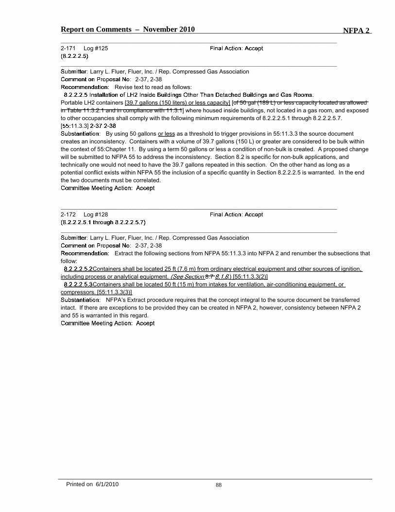
Report on Comments – November 2010 NFPA 2_______________________________________________________________________________________________2-171 Log #125
_______________________________________________________________________________________________Larry L. Fluer, Fluer, Inc. / Rep. Compressed Gas Association
2-37, 2-38Revise text to read as follows:
Portable LH2 containers [39.7 gallons (150 liters) or less capacity] [of 50 gal (189 L) or less capacity located as allowedin Table 11.3.2.1 and in compliance with 11.3.1] where housed inside buildings, not located in a gas room, and exposedto other occupancies shall comply with the following minimum requirements of 8.2.2.2.5.1 through 8.2.2.2.5.7.[ 11.3.3]
By using 50 gallons or less as a threshold to trigger provisions in 55:11.3.3 the source documentcreates an inconsistency. Containers with a volume of 39.7 gallons (150 L) or greater are considered to be bulk withinthe context of 55:Chapter 11. By using a term 50 gallons or less a condition of non-bulk is created. A proposed changewill be submitted to NFPA 55 to address the inconsistency. Section 8.2 is specific for non-bulk applications, andtechnically one would not need to have the 39.7 gallons repeated in this section. On the other hand as long as apotential conflict exists within NFPA 55 the inclusion of a specific quantity in Section 8.2.2.2.5 is warranted. In the endthe two documents must be correlated.
_______________________________________________________________________________________________2-172 Log #128
_______________________________________________________________________________________________Larry L. Fluer, Fluer, Inc. / Rep. Compressed Gas Association
2-37, 2-38Extract the following sections from NFPA 55:11.3.3 into NFPA 2 and renumber the subsections that
follow:Containers shall be located 25 ft (7.6 m) from ordinary electrical equipment and other sources of ignition,
including process or analytical equipment. 8.7 .) [55:11.3.3(2)]Containers shall be located 50 ft (15 m) from intakes for ventilation, air-conditioning equipment, or
compressors. [55:11.3.3(3)]NFPA’s Extract procedure requires that the concept integral to the source document be transferred
intact. If there are exceptions to be provided they can be created in NFPA 2, however, consistency between NFPA 2and 55 is warranted in this regard.
88Printed on 6/1/2010

Report on Comments – November 2010 NFPA 2_______________________________________________________________________________________________2-173 Log #122
_______________________________________________________________________________________________Larry L. Fluer, Fluer, Inc. / Rep. Compressed Gas Association
2-1Revise text to read as follows:
****Insert Include 2_L122_R.doc Here****
The table created by NFPA 2 extracts requirements from the flammable compressed gas tables foundin Section 7.6.2 of NFPA 55. The use of this table and associated requirement is not coordinated with NFPA 55. Table8.7.3 of NFPA 55 is a generic table for all cryogens. If material specific requirements are different then they must bespecified by NFPA 55 Chapter 11. Using Table 8.7.3 from NFPA 55 returns the concept to the minimum distancesspecified in NFPA 55 for the generic category of cryogenic fluids. This does not solve the problem with building exits,wall openings and air intakes where the separation distance is driven by the material specific requirements of Sections8.2.2.3.4.2 and 8.2.2.3.4.3.
One option would be to include the distances from Sections 8.2.2.3.4.2 and 3, the other option is to refer the user tothe appropriate section to gain a better understanding of the requirements.
Revise Table 8.2.2.3.4.2 as follows:Portable containers located outdoors shall
be separated from exposure hazards in accordance with Table 8.7.3. 8.7.3]The outdoor use of [LH2] [flammable compressed gas] shall be located from lot lines, public streets, public alleys, publicways, or buildings not associated with the manufacture or distribution of [GH2] [such gases] in accordance with Table8.2.2.3.4. [ 7.6.2]
***INSERT TABLE 2_L122_CA.doc***
Modification of existing Table 8.2.2.3.4 is being made in lieu of using an extract of 55:Table8.7.3 as originally proposed in the public comment. Footnotes have been provided to refer the user to specificseparation distances found in Sections 8.2.2.3.4.2 and 8.2.2.3.4.3 to aid the user with the identification of distances thatappear elsewhere in the document in text. The Manual of Style (MOS) seeks to avoid having requirements appear asfootnotes to tables. In this instance the footnotes provide a reference that will allow the user to access detailedrequirements.
89Printed on 6/1/2010
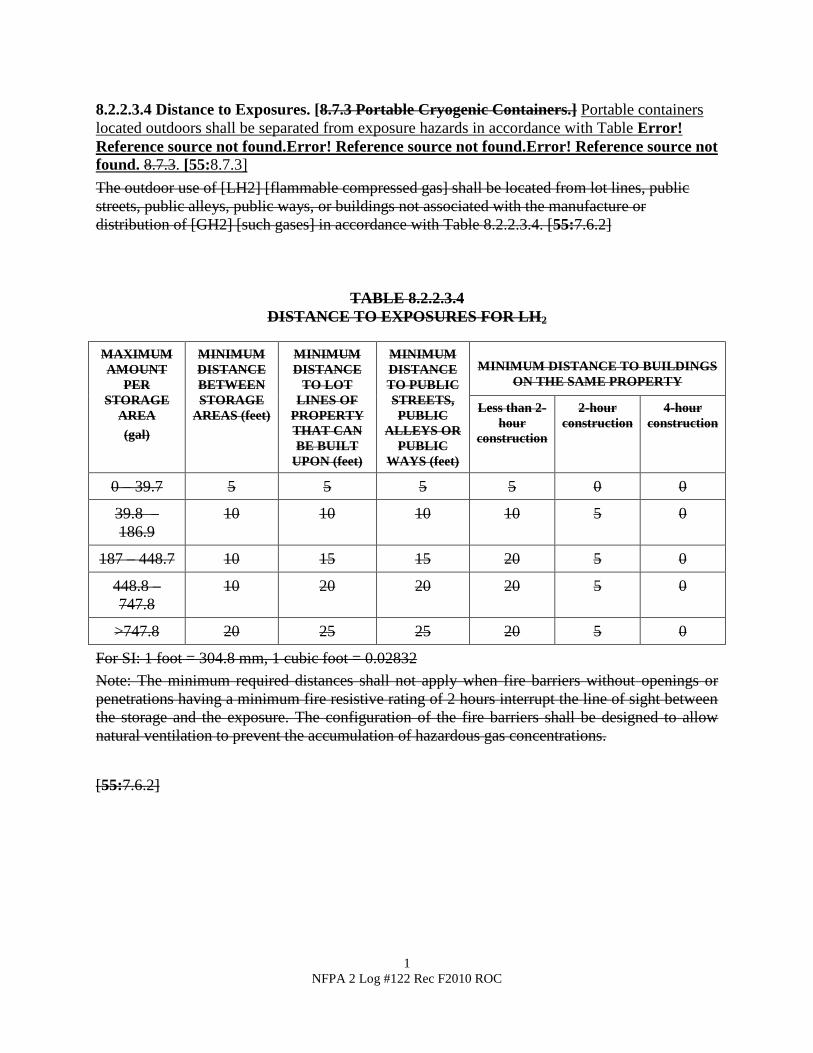
1
NFPA 2 Log #122 Rec F2010 ROC
8.2.2.3.4 Distance to Exposures. [8.7.3 Portable Cryogenic Containers.] Portable containers
located outdoors shall be separated from exposure hazards in accordance with Table Error!
Reference source not found.Error! Reference source not found.Error! Reference source not
found. 8.7.3. [55:8.7.3]
The outdoor use of [LH2] [flammable compressed gas] shall be located from lot lines, public
streets, public alleys, public ways, or buildings not associated with the manufacture or
distribution of [GH2] [such gases] in accordance with Table 8.2.2.3.4. [55:7.6.2]
TABLE 8.2.2.3.4
DISTANCE TO EXPOSURES FOR LH2
MAXIMUM
AMOUNT
PER
STORAGE
AREA
(gal)
MINIMUM
DISTANCE
BETWEEN
STORAGE
AREAS (feet)
MINIMUM
DISTANCE
TO LOT
LINES OF
PROPERTY
THAT CAN
BE BUILT
UPON (feet)
MINIMUM
DISTANCE
TO PUBLIC
STREETS,
PUBLIC
ALLEYS OR
PUBLIC
WAYS (feet)
MINIMUM DISTANCE TO BUILDINGS
ON THE SAME PROPERTY
Less than 2-
hour
construction
2-hour
construction
4-hour
construction
0 – 39.7 5 5 5 5 0 0
39.8 –
186.9
10 10 10 10 5 0
187 – 448.7 10 15 15 20 5 0
448.8 –
747.8
10 20 20 20 5 0
>747.8 20 25 25 20 5 0
For SI: 1 foot = 304.8 mm, 1 cubic foot = 0.02832
Note: The minimum required distances shall not apply when fire barriers without openings or
penetrations having a minimum fire resistive rating of 2 hours interrupt the line of sight between
the storage and the exposure. The configuration of the fire barriers shall be designed to allow
natural ventilation to prevent the accumulation of hazardous gas concentrations.
[55:7.6.2]

2
NFPA 2 Log #122 Rec F2010 ROC
Table 8.7.3 Minimum Separation
Distance Between Portable Cryogenic
Containers and Exposures
Minimum
Distance
Exposure ft m
Building exits See
8.2.2.3.4.3
10 3.1
Wall openings See
8.2.2.3.4.3
1 0.3
Air intakes See 8.2.2.3.4.2 10 3.1
Property lines 5 1.5
Room or area exits 3 0.9
Combustible materials,
(e.g., paper, leaves, weeds,
dry grass, debris)
15 4.5
Incompatible hazardous
materials
20 6.1
[55:8.7.3]
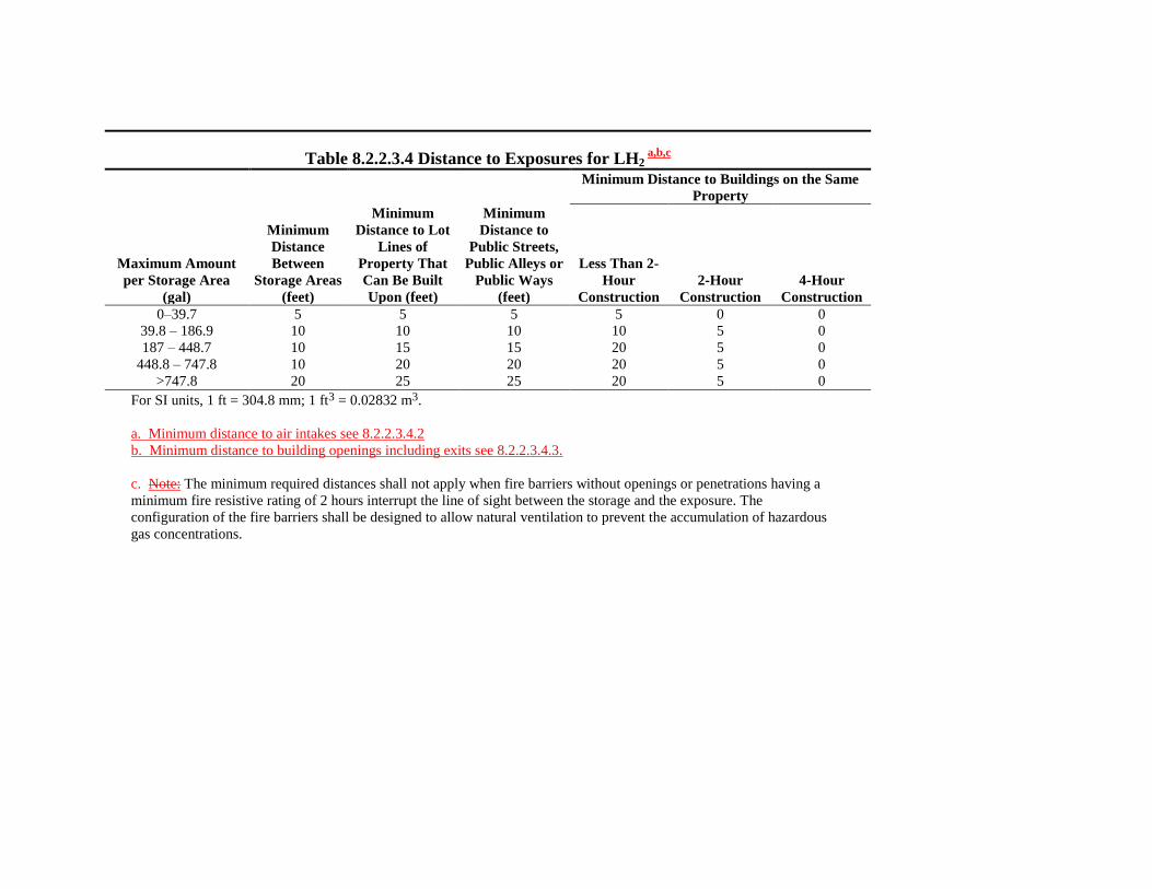
Table 8.2.2.3.4 Distance to Exposures for LH2 a,b,c
Minimum Distance to Buildings on the Same
Property
Maximum Amount
per Storage Area
(gal)
Minimum
Distance
Between
Storage Areas
(feet)
Minimum
Distance to Lot
Lines of
Property That
Can Be Built
Upon (feet)
Minimum
Distance to
Public Streets,
Public Alleys or
Public Ways
(feet)
Less Than 2-
Hour
Construction
2-Hour
Construction
4-Hour
Construction
0–39.7 5 5 5 5 0 0
39.8 – 186.9 10 10 10 10 5 0
187 – 448.7 10 15 15 20 5 0
448.8 – 747.8 10 20 20 20 5 0
>747.8 20 25 25 20 5 0
For SI units, 1 ft = 304.8 mm; 1 ft3 = 0.02832 m3.
a. Minimum distance to air intakes see 8.2.2.3.4.2
b. Minimum distance to building openings including exits see 8.2.2.3.4.3.
c. Note: The minimum required distances shall not apply when fire barriers without openings or penetrations having a
minimum fire resistive rating of 2 hours interrupt the line of sight between the storage and the exposure. The
configuration of the fire barriers shall be designed to allow natural ventilation to prevent the accumulation of hazardous
gas concentrations.
Report on Comments – November 2010 NFPA 2_______________________________________________________________________________________________2-174 Log #231
_______________________________________________________________________________________________Larry L. Fluer, Fluer, Inc. / Rep. Compressed Gas Association
2-1Delete Section 8.2.2.3.4.1 and replace it with the following:
Where a fire barrier is used to protect [LH2] [compressed gas] systems, the system shall terminate downstream ofthe source valve. [ 7.7.2.1.1]
The fire barrier wall shall be either an independent structure or the exterior wall of the building adjacent to thestorage area. [ 7.7.2.1.2]
The fire barrier wall shall be without openings or penetrations. [ 8.7.2.1.1]Penetrations of the fire barrier wall by conduit or piping shall be permitted provided that the penetration is protected
with a fire stop system in accordance with the adopted building code. [ 8.7.2.1.1.1]The configuration of the fire barrier shall be designed to allow natural ventilation to prevent the accumulation of
hazardous gas concentrations. [ 7.6.2.3]A 2-hour fire barrier wall shall be permitted in lieu of the distances specified by Table
[8.2.2.4.3] [8.7.3] when in accordance with [items (A) through (D) below [the provisions of 8.7.3.1.1 through 8.7.3.1.4].[ :8.7.3.1]
(A)The fire barrier wall shall be without openings or penetrations. [ :8.7.3.1.1](B) Penetrations of the fire barrier wall by conduit or piping shall be permitted provided that the penetration is protected
with a fire-stop system in accordance with the building code. [ :8.7.3.1.1.1](C) The fire barrier wall shall be either an independent structure or the exterior wall of the building adjacent to the
storage system. [ :8.7.3.1.2](D) The fire barrier wall shall be located not less than 5 ft (1.5 m) from any exposure. [ :8.7.3.1.3]
Section 8.2.2.3.4.1 has been extracted from Section 7.7 of NFPA 55 which is for oxidizing compressedgases. The extract should come from Chapter 8 of NFPA 55 which is a generic chapter for cryogenic gases.
Delete Section 8.2.2.3.4.1 and replace it with the suggested text as follows:
Where a fire barrier is used to protect [LH2] [compressed gas] systems, the system shall terminate downstream ofthe source valve. [ 7.7.2.1.1]
The fire barrier wall shall be either an independent structure or the exterior wall of the building adjacent to thestorage area. [ 7.7.2.1.2]
The fire barrier wall shall be without openings or penetrations. [ 8.7.2.1.1]Penetrations of the fire barrier wall by conduit or piping shall be permitted provided that the penetration is protected
with a fire stop system in accordance with the adopted building code. [ 8.7.2.1.1.1]The configuration of the fire barrier shall be designed to allow natural ventilation to prevent the accumulation of
hazardous gas concentrations. [ 7.6.2.3]A 2-hour fire barrier wall shall be permitted in lieu of the distances specified by Table
[8.2.2.4.3] [8.7.3] when in accordance with [items (A) through (D) below [the provisions of 8.7.3.1.1 through 8.7.3.1.4].[ :8.7.3.1]
(A)The fire barrier wall shall be without openings or penetrations. [ :8.7.3.1.1](B) Penetrations of the fire barrier wall by conduit or piping shall be permitted provided that the penetration is protected
with a fire-stop system in accordance with the building code. [ :8.7.3.1.1.1](C) The fire barrier wall shall be either an independent structure or the exterior wall of the building adjacent to the
storage system. [ :8.7.3.1.2](D) The fire barrier wall shall be located not less than 5 ft (1.5 m) from any exposure. [ :8.7.3.1.3](E) The fire barrier wall shall not have more than two sides at approximately 90 degree (1.57 rad) directions or not
more than three sides with connecting angles of approximately 135 degrees (2.36 rad). [55:8.7.3.1.4]NFPA 55 paragraph 8.7.3.1.4 was added to follow the extract policy and insert a missing
portion in NFPA 2 on the use of fire barrier walls, consistent with the approach taken in NFPA 55.
90Printed on 6/1/2010
Report on Comments – November 2010 NFPA 2_______________________________________________________________________________________________2-175 Log #123
_______________________________________________________________________________________________Larry L. Fluer, Fluer, Inc. / Rep. Compressed Gas Association
2-1Revise text to read as follows:
8.2.2.3.9.2 The stationary container shall not be placed where spilled or discharged [LH2] [fluids] will be retainedaround the container. [See 8.2.2.3.7] [ 8.13.2.6.2]
Diking is not to be used to retain LH2 spills. The cross reference to Section 8.2.2.3.7 is used to alertusers that may seek to dike other materials and inadvertently include the LH2 system. Section 6.14.2 is a generalprohibition against diking. Section 8.2.2.3.9.2 is redundant to 6.14.2.
The alternative to adding the reference Sections 8.2.2.3.7, 8.2.2.3.9.2, 8.3.2.1.2, 8.3.2.4.3 and 8.3.2.4.5.2 could all bedeleted thereby allowing 6.14.2 to control the requirements. A separate comment has been issued to delete 8.3.2.4.3.
_______________________________________________________________________________________________2-176 Log #CC11
_______________________________________________________________________________________________Technical Committee on Hydrogen Technology,
2-1Provide annex material for 8.3.1.2.1.1 as follows:
Steel supports in excess of 18 in. (46 cm) in height shall have a minimum 2-hour fire resistance rating inaccordance with ASTM E 1529,
. [55:11.2.1.1]Refer to Figure A.8.3.1.2.1 for application of the 18 in (46 cm) dimension to typical tank supports.
***INSERT Figure A.8.3.1.2.1 HERE***
It is not uncommon for portions of supports to extend beyond the 18 inch limit. The extent to whichfireproofing must be carried has been inconsistently interpreted in the field. Having a diagram that illustrates the intentof the provision will aid in uniform application of the code. As can be seen from the illustration there can becircumstances where portions of the supports extend to a level above the tank which is not required to be fireproofed.Spillage of LH2 which remains in a liquid form around a tank is not expected beyond a time period measured inseconds. The application of fire proofing based on pooled liquid fires at tank supports is felt to be conservative. Lackingany specific data to the contrary the determination of a height for protection to heights greater than 18 inches isspeculative.
91Printed on 6/1/2010
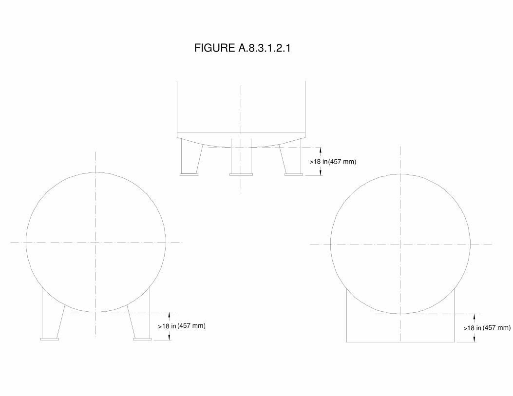
FIGURE A.8.3.1.2.1
18 in>
18 in> >18 in
(457 mm)
(457 mm)(457 mm)

Report on Comments – November 2010 NFPA 2_______________________________________________________________________________________________2-177 Log #126
_______________________________________________________________________________________________Larry L. Fluer, Fluer, Inc. / Rep. Compressed Gas Association
2-37Revise text to read as follows:
Welding or cutting operations and smoking shall be prohibited while hydrogen is in the room, and signsshall be provided as required by 4.14.3. [Also See 4.13] [ 11.3.3(7)]
The reference to Section 4.13 sends the user to the general requirements for ignition source controlwhich include precautions to address the use of open flames. Welding, cutting and smoking are not the only concerns.
_______________________________________________________________________________________________2-178 Log #127
_______________________________________________________________________________________________Larry L. Fluer, Fluer, Inc. / Rep. Compressed Gas Association
2-1Delete 8.3.2.4.3 and renumber the following sections.
Containers of [LH2] [cryogenic fluids] shall not belocated within diked areas with other hazardous materials. [ 8.13.2.4]
Section 8.3.2.1.2 is a general prohibition against diking of LH2 containers which has been extractedfrom Chapter 11 of NFPA 55. Section 8.3.2.4.3 was extracted from Chapter 8 of NFPA 55 which is a “generic” chapterfor all cryogens including liquid nitrogen, argon, etc. The material specific requirements for bulk hydrogen systems arefound in Chapter 11 and specific requirements always take precedent over general requirements. Deleting 8.3.2.4.3eliminates the confusion and allows Section 8.3.2.1.2 to clearly state the prohibitions involving diking for LH2.
_______________________________________________________________________________________________2-179 Log #CC12
_______________________________________________________________________________________________Technical Committee on Hydrogen Technology,
2-37
Tanks not in service shall be maintained in accordance with 8.3.2.5.10.2. [ 11.4.3.10]Users should notify suppliers where a tank is to be left in place, but not refilled for an extended period of
time. The supplier may inert the tank or otherwise prepare the tank for ultimate removal.
Tanks that are not in service are of interest so that they are properly protected. If LH2 is to bedepleted it is common for tanks to be backfilled with an atmosphere of nitrogen or other inert gas as a means to preventthe intrusion of air and moisture. In the majority of cases the tank is leased by the user, and notification of the supplierensures that steps be taken to avoid circumstances that may have a negative influence on the future life of the tank.
92Printed on 6/1/2010
Report on Comments – November 2010 NFPA 2_______________________________________________________________________________________________2-180 Log #CC10
_______________________________________________________________________________________________Technical Committee on Hydrogen Technology,
2-1Modify Section 8.3.4.5.9 and insert new definitions as follows:
When the fueling facility tank to be filled or the attendant transfer equipment is located in an area belowgrade, controls shall be provided and visible to the operator to prevent overfilling of the tank. The controls operatingstatus indicators, such as those that indicate container level, shall be provided in the unloading area and as a minimumshall include a liquid level indicator, pressure indicator and a full trycock. [ :14.4.3.1]
A valve connected to a line inserted into the inner tank of a cryogenic fluid tank and positionedsuch that liquid just begins to flow from the valve when opened.
The full trycock valve provides a physical indication of the filling status of a liquid tank and ittypically used as a redundant means to that of other liquid level indicators. A full trycock line is used to connect theinner vessel vapor space near the top of a cryogenic fluid tank with an internal dip tube located at a point equivalent tothe net liquid capacity of the tank. The vapor space in the inner vessel above the full try-cock level is considered thetank ullage. The tank is determined to be full when liquid is emitted from the full trycock valve when the valve is opened.
The requirement to observe the status of a tank in an area below grade is applicable to all tanks, notjust those used in fueling applications. Controls must be provided in an area where the delivery operator can determinethe status of the tank. As a minimum pressure, liquid level and full trycock controls must be provided. The term “fulltrycock” is understood by the industry, but a definition is needed to inform the user as to the purpose of the device. The“trycock” is, in fact, a valve that is normally manually operated as a redundant means to verify liquid level that may beindicated by instrumental means.
_______________________________________________________________________________________________2-181 Log #49
_______________________________________________________________________________________________Martin T. Gresho, FP2Fire, Inc.
2-43Delete the following text:
– The material presented in Chapter 9 is in outline form. The TechnicalCommittee has an ongoing effort to develop the detailed content and associated Annex material addressing hydrogenexplosions. The technical committee has included a chapter outline in the committee draft in order to solicit public inputon desired content for such a Chapter and Annex. Public comments received on the content of this draft will beconsidered in developing the content of the chapter as progress continues.
This text was inserted in the pre-ROP draft in an effort explain that Ch 9 was not yet presented inenforceable text and was primarily an effort to solicit public input on the subject. The committee note is no longerappropriate.
93Printed on 6/1/2010

Report on Comments – November 2010 NFPA 2_______________________________________________________________________________________________2-182 Log #129
_______________________________________________________________________________________________Larry L. Fluer, Fluer, Inc. / Rep. Compressed Gas Association
2-43Delete Chapter 9 text in its current form in its entirety or revise to provide prescriptive requirements.
Chapter 9 in its present form is not code ready. It may be that the Task Group working on this chapterwill submit a revised document for consideration during the ROC meeting. If this is not the case, the chapter should beheld as a reserved Chapter without content, or alternatively limited content yet to be proposed by the task group, untilthe next code cycle. As described by Section 4.4.1 NFPA 2 is primarily a prescriptive code document, and Chapter 9has not been excepted from the prescriptive approach.
See the committee action taken on 2-183 (Log #50).
94Printed on 6/1/2010
Report on Comments – November 2010 NFPA 2_______________________________________________________________________________________________2-183 Log #50
_______________________________________________________________________________________________Martin T. Gresho, FP2Fire, Inc.
2-43Revise text to read as follows:
This chapter (in combination with specifications in other NFPA 2 chapters) will specify when evaluations are needed forthe various types of explosions, and will describe hydrogen explosion hazard evaluation methods. It will also cite orextract existing explosion prevention measures and damage/injury mitigation measures in other NFPA standards. Thefollowing five generic hydrogen explosion scenarios will be addressed:
Unconfined Hydrogen Combustion Explosions; Partially Confined Hydrogen Combustion Explosions; HydrogenExplosions in Piping, Electrical Conduit and Elongated Enclosures; and Hydrogen Pressure Vessel Burst Preventionand Mitigation.
In the first four types of hydrogen explosions, the influence of hydrogen gas concentrations and obstructions will beincluded, and explosion evaluation methods will be described.
9.2.1 Threshold Amount of Hydrogen for Unconfined Explosion Risk Evaluation9.2.1.1 When the aggregate amount of hydrogen at a process exceeds 10,000 lb (4540 kg), the risk of an unconfined
explosion shall be evaluated using a risk-based approach to the amount of hydrogen released and the consequences ofan unconfined hydrogen explosion.
9.2.1.2 When the aggregate amount of hydrogen at a process exceeds 1,000 lb (454 kg), the potential for a largehydrogen release into an area with congested piping and equipment shall be determined and documented. Thedetermination shall include considerations of potential release sites, prevention and control measures to limit the extentand duration of the release, and the potential for hydrogen accumulation in the area of the congested piping andequipment. The potential consequences of the largest credible release into such a congested area will be evaluatedand documented.
9.2.2 Facilities satisfying the conditions listed in 1) or 2) below are exempt from the unconfined explosion evaluationand prevention documentation described in 9.2.1.
1) Processes with an aggregate amount of hydrogen less than 1,000 lb (454 kg)2) Facilities that do not store more than 50 kg of hydrogen in any single vessel or container.A.9.2 AppendixThe 10,000 lb (4540 kg) threshold in 9.2.1.1 is the hydrogen threshold quantity for applicability of the EPA Risk
Management Plan (RMP) regulations. The EPA RMP defines a process as "Any activity involving a regulated substance,including any use, storage, manufacturing, handling, or on-site movement of such substances, or combination of theseactivities. For the purposes of this definition, any group of vessels that are interconnected, or separate vessels that arelocated such that a regulated substance could be involved in a potential release, shall be considered a single process."CGA P-28 provides guidance on liquid hydrogen facility compliance with the EPA RMP. the evaluation required in 9.2differs from the worst-case analysis required in the EPA RMP regulation in that the facility owner will evaluate theamount of hydrogen that can be released and that can contribute to an unconfined hydrogen-air mixture vapor cloudexplosion. The 1,000 lb (454 kg) threshold in 9.2.2 corresponds to approximately the amount of liquid hydrogen in a1500 gallon tank.
Unconfined hydrogen explosions only occur with at least 40 kg hydrogen released into an unobstructed open area insuch a way that at least 20 kg develops near stoichiometric concentrations, or with at least 0.50 kg hydrogen into ahighly obstructed area such that the at least 0.50 kg forms a flammable cloud or jet. Appendix examples will be writtento explain the types of obstructions that promote hydrogen flame accelerations and associated explosion pressures. Theinformation will be presented to provide a method for determining whether an unconfined hydrogen explosion hazardexists with different amounts of hydrogen storage and obstructed equipment/piping. Another aspect of this method isthe best available information on when auto-ignition of a high pressure hydrogen release should be anticipated.● Another part of this chapter will provide requirements for blast hardening of control rooms and other normally
occupied structures near large outdoor hydrogen storage and processing facilities. The methodology for these blasthardening requirements will be the Baker-Strehlow and/or Dorofeev vapor cloud explosion blast wave calculationmethod adjusted as necessary by data comparisons with large-scale hydrogen explosion test data presented at the2005 and 2007 International Symposium on Hydrogen Safety.
95Printed on 6/1/2010

Report on Comments – November 2010 NFPA 29.3.1 Partially confined explosion evaluation shall be required where amounts of GH2 or LH2 in storage or use
exceed the quantity thresholds requiring special provisions, as specified in other chapters of NFPA 2, and where thisamount of hydrogen is stored along with piping and other process or compression equipment in an area with two ormore walls, or one wall and a canopy or roof.
9.3.2 The partially confined explosion evaluation will include a description of the potential for blast damage and injuriesas well as preventive or mitigation measures to minimize the likelihood or consequences of such damage and injuries.9.3.3 The partially confined explosion evaluation will be made available to the AHJ.
A.9.3 Appendix●The threat of a hydrogen explosion in a partially confined area depends on the hydrogen concentration distribution,
potential ignition sources, the amount of confinement, and the presence of various types of obstructions. Explanationsof the combined influence of these parameters will be provided to assist in the determination of how increased levels ofconfinement affect the hydrogen explosion hazard.
●Appendix guidelines for explosion pressure and blast wave evaluations will be developed based on the amount ofhydrogen that can be stored and used in highly obstructed areas (with and without electrical hazardous locationclassifications) with different degrees of confinement. The basis for these new limitations will be cited large-scale testdata from a variety of sources that have been published during the last 25 years. References will be listed to allow userfollow up and development of alternative partially confined explosion evaluation methods.
9.4.1 This section will send the user to the confined hydrogen explosion protection measures presented in section 6.8of NFPA 2 for enclosures with length-to-diameter ratios less than 3:1.
●An appendix method will be described to determine the minimum amount of hydrogen for an explosion with pressuresgreater than an enclosure damage threshold pressure. The method will be developed using analyses for partial volumedeflagrations. Appendix examples will be provided describing the use of this method for perhaps a completely enclosedfueling station, a repair garage, and a laboratory.
●Appendix elaboration on explosion suppression applicability and explosion venting applicability to hydrogen will beprovided.
●The Appendix section for 9.4.1 will also explain that extreme turbulence, large obstacle/enclosure surface area ratios,large length/diameter ratios, and explosion propagation into interconnected enclosures can lead to flame accelerationsthan can render explosion venting or suppression ineffective, and may possibly result in deflagration-to-detonationtransition. It will refer to A.9.5.1 for examples and sample test data.
9.4.2 This section will also cite or extract existing NFPA ignition source control measures applicable to confinedareas. These include:
1) NFPA 497 to provide specific requirements on the extent of electrical hazardous location classified areas for alighter- than-air flammable gas with various ventilation provisions.
2) Electrostatic controls per NFPA 77 for flammable gases such as hydrogen with a low Minimum Ignition Energy3) Other ignition source control measures in NFPA 69-2008 Chapter 9.4) Prevention by Ventilation: NFPA 69-2008 Chapter 8 Requirements and extensions to account for partial volume
flammable mixtures.5) Prevention by Oxygen Concentration Reduction: NFPA 69-2008 Chapter 7 Requirements
9.5.1 When the hydrogen applicable hazardous area classifications in NFPA 497 indicate the Division 1 or Division 2(Zone 0, 1 or Zone 2) hydrogen-air area occupies at least 25% of the volume in an enclosure with a length/diameter(L/D) ratio greater than about 3, a separate explosion evaluation is required. The special explosion evaluation shallassess the limitations of deflagration venting and suppression do to potentially fast flame speed development. Thedeflagration-to-detonation transition (DDT) potential shall also be evaluated qualitatively. The possible need for specialexplosion protection measures, beyond those described in NFPA 2 Section 6.8, will be determined and implemented.
A.9.5.1 The Appendix item for this section will cite pertinent data on flame acceleration and DDT potential in elongatedenclosures for different hydrogen concentrations levels of obstruction, and turbulence levels, as well as enclosureeffective diameter. Protection Requirements required for piping; effect of piping diameter and L/D ratio on detonationpropagation potential; detonation cell size data.
9.5.2 Where specified in other chapters of NFPA 2, the need for Deflagration and Detonation Flame Arresters inhydrogen piping and vents will be assessed. Requirements for hydrogen deflagration and detonation arresters perNFPA 69 chapter 12 will be cited or extracted.
9.5.3 Electrical conduit and connectors in electrically classified areas shall be sealed per NFPA 70 requirements toprevent the development of hydrogen-air mixtures in those conduits.
A.9.5.3 An appendix paragraph will explain how reliable conduit sealing can be a DDT prevention measure and how it
96Printed on 6/1/2010

Report on Comments – November 2010 NFPA 2is related to NEC 70 requirements for the electrical equipment in these Class 1, Division 1 or 2, Group B areas.
●Cite hydrogen embrittlement prevention material requirements contained elsewhere in NFPA 2 and in the ASMEhydrogen piping code.
●Cite CGA and ASME pressure vessel vent requirements for hydrogen.●Cite Pressure Vessel and relief valve inspection and NDE requirements contained elsewhere in NFPA 2 or the ASME
Boiler and Pressure Vessel code.●Cite prevention measures in other NFPA 2 chapters to prevent inadvertent vessel over-pressurization●In the appendix, describe or reference available blast wave pressure and impulse calculation methods. The use of
these methods will not be required except possibly for performance based design methods for pressure vessels thatdiffer from the prescriptive methods in NFPA 2 and the ASME Boiler and Pressure Vessel code.
●Available design methods for near-field blast mitigation via blast walls will be described in the Appendix but will not berequired unless it is proposed as a performance based design alternative to the prescriptive measures in NFPA 2 toprevent pressure vessel failure.
CGA P-28, “Risk Management Plan Guidance Document for Bulk Liquid Hydrogen Systems,” 2nd Edition, CompressedGas Association, 2003.
Dorofeev, S. (2007). "A Flame Speed Correlation for Unconfined Gaseous Explosions." Process Safety Progress26(2): 140-149.
Environmental Protection Agency, Risk Management Plan Regulation, Code of Federal Regulations (CFR) 40 CFR68.130, see also http://www.epa.gov/oem/content/rmp/rmp_guidance.htm#General.
Mercx, W., and van den Berg, A. (1997). The Explosion Blast Prediction Model in the Revised "Yellow Book". 31stAnnual AIChE Loss Prevention Symposium.
Molkov, V., Makarov, D. and Schneider, H. (2005). Hydrogen-Air Deflagrations in Open Atmosphere: Large EddySimulation of Experimental Data. 1st International Conference on Hydrogen Safety. Pisa, Italy.
Pierorazio, J., Thomas, Q., Baker, Q. and Ketchum, D. (2005). "An Update to the Baker-Strehlow-Tang Vapor CloudExplosion Prediction Methodology Flame Speed Table." Process Safety Progress : 59-65.
Shirvill, L. C. R., M.and Roberts, T.A. (2007). Hydrogen Releases Ignited In A Simulated Vehicle RefuellingEnvironment, 2nd International Conference on Hydrogen Safety San Sebastian, SpainTang, M. a. B., Q. ( 1999). A New Set of Blast Curves from Vapor Cloud Explosions. 33rd Annual AIChE LossPrevention Symposium.
9.1 GeneralReserved9.2 Explosion Protection – Non-Bulk Hydrogen SystemsReserved9.3 Unconfined Hydrogen Combustion ExplosionsReserved9.4 Partially Confined Hydrogen Combustion ExplosionsReserved9.5 Hydrogen Explosions in Compact EnclosuresReserved9.6 Hydrogen Explosions in Piping, Electrical Conduit and Elongated EnclosuresReserved9.7 Hydrogen Pressure Vessel Burst Prevention and MitigationReserved
The text in the ROP draft was intended to be replaced by a proposal (ROP 2-43) from Task Group 10(Explosions) which was to contain enforceable text. However, the TC rejected ROP Log 2-43 developed by Task Group10 because further development was felt to be needed, resulting in retention of the pre-ROP draft language for Chapter9. This comment deletes the pre-ROP text in Chapter 9 which is unacceptable in a enforceable chapter of NFPA 2 andreplaces it with the major section titles to inform the public regarding the intended path forward for Chapter 9. Insummary, the Explosions Task Group is recommending that Chapter 9 be listed as “reserved” and that a new Annex(submitted via separate comment) be created with the proposed text for Chapter 9 in this edition. This strategy will allowthe new code text to be non-mandatory for one NFPA 2 cycle. The new Annex will include a note that the text will befurther developed as needed and moved up to the enforceable Chapter 9 as part of the next ROP for NFPA 2.
Delete Chapter 9 and replace the text with the following:
97Printed on 6/1/2010
Report on Comments – November 2010 NFPA 2[Reserved]
See Annex L Generalized Explosion Protection for informational purposes.The committee met the proponent's intent by creating the reserved chapter (See action on 2-98
(Log #CC2).
_______________________________________________________________________________________________2-184 Log #180
_______________________________________________________________________________________________Glenn Mahnken, FM Global
2-1Add new text as follows:
Dispensing and storage facilities shall be certified as meeting the requirements of this Code by qualifiedengineer(s) with expertise and competence in the design, fabrication, and construction of hydrogen containers, pipingsystems, site fire protection, gaseous detection, emergency shutdown provisions, isolation, drainage, site spacing, fireprotection equipment, explosion control, operating procedures, worker protection, and other components of the facility.[ 9.2.2]
A hazard analysis shall be conducted on every hydrogen fueling system installation by a qualifiedengineer(s) with proven expertise in the hazards, design and operation of hydrogen fueling systems and installations.[ 9.2.3]
The hazard analysis shall include the following explosion and fire protection measures: fire protection andsuppression systems, explosion control, detection systems, and ventilation. [ 9.2.3.1]
The hazard analysis shall include consideration of potential failures in hoses, nozzles, dispensingequipment, and emergency shutdown system, as well as operator errors and failures for during maintenance andservice. [ 9.2.3.2]
The hazard analysis, including all supporting documentation, schematics and drawings, shall be submittedto AHJ for Approval and a copy shall be provided to the Owner and kept on file on site for the life of the installation.
The hazard analysis shall be reviewed and updated at least every 3 years and whenever changes are madeto the installation.
adds explosion control as a required expertiseClarifies the expertise needed to conduct a hazards analysisincludes explosion hazards in the hazards analysisadds more contributing factors to be considered in the hazards analysisGood practiceStandard practice
Paragraph 10.2.1.1.1 establishes requirements for storage facilities as extracted from NFPA52. However, the detailed requirements for storage facilities are under the purview of NFPA 55. Attempting to expandthe requirements for storage by modifying NFPA 52 text is in conflict with the decision relegating the responsibility forstorage, given to the 55 committee by the Standards Council. The committee disagrees with a requirement for the AHJto review every three years. The committee believes that the proponent's substantiation was insufficient to warrant thedesired change.
98Printed on 6/1/2010

Report on Comments – November 2010 NFPA 2_______________________________________________________________________________________________2-185 Log #153
_______________________________________________________________________________________________Mihai Ursan, Westport Power Inc.
2-1Recommend extraction of the exact text from 52: 5.2.1.
(4) Valves [, fittings and tubing] [52:5.2.1]This proposal corrects errors in the extraction. This proposal is part of the result of NFPA 52 Task
Group efforts.
_______________________________________________________________________________________________2-186 Log #152
_______________________________________________________________________________________________Mihai Ursan, Westport Power Inc.
2-1Revise to read as follows:
NFPA 2:Pressure relief devices shall be in accordance with Section 7.1.5.5. [ 9.6.1]
When required by 7.1.5.5.2, pressure relief devices shall be provided to protect containers and systemscontaining [GH2] [compressed gases] from rupture in the event of overpressure from thermal exposure. [ 7.1.5.5.1]
NFPA 52:PRDs shall be in accordance with 9.6.1.1 through 9.6.1.2.
PRDs shall be so arranged that they discharge in accordance with Section 5.4.An overpressure protection device, other than a rupture disc, shall be installed in the fueling transfer system to
prevent overpressure in the vehicle.When required by 5.4.1, pressure relief devices shall be provided to protect containers
and systems containing compressed gases from rupture in the event of overpressure from thermal exposure.[ 7.1.5.5.1]
Pressure relief valves for GH2 service shall not be fitted with lifting devices.Proposal: Use a single reference, suggest [52:9.6.1]
This proposal corrects errors in the extraction. This proposal is part of the result of NFPA 52 TaskGroup efforts.
Section 2-7.1.5.5 is smaller in scope than the 52-9.6.1. The referenced paragraphs have different content. Byreferencing 2-7.1.5.5 some content of 52 is not used, 52-5.4 has more content than the common reference 55:7.1.5.5.1.
Following the reference to section 2-7.1.5.5 it leads to the content of 55:7.1.5.5.1. Following the extraction [52:9.6.1] itleads to section 52-5.4 that leads to the content of 55:7.1.5.5.1. and in addition has original requirements: 52-5.4.6;5.4.7.
This log was not submitted in legislative format so the intent is not clear.However, the Proponent cites extract from 55:7.1.5.5.1 for NFPA 2 Section 7.1.5.5.1 and states that the correct extract
should be NFPA 52.NFPA 2 ROC ROP final version cites extract from 52:9.6.1 which agrees with the proponent’s suggestion including all
the paragraphs cited.
99Printed on 6/1/2010

Report on Comments – November 2010 NFPA 2_______________________________________________________________________________________________2-187 Log #151
_______________________________________________________________________________________________Mihai Ursan, Westport Power Inc.
2-1Revise to read as follows:
NFPA 2Pressure relief devices shall be so arranged that they discharge in accordance with Section 6.16 and
7.1.5.5.5. [ 9.6.1.1]Pressure-relief devices shall be arranged to discharge unobstructed to the open air in such a manner as to
prevent any impingement of escaping gas upon the container, adjacent structures, or personnel. This requirement shallnot apply to DOT specification containers having an internal volume of 2.0 ft3 (0.057 m3) or less. [ 7.1.5.5.5]
NFPA 52PRDs shall be so arranged that they discharge in accordance with Section 5.4.
When required by 5.4.1, pressure relief devices shall be provided to protect containersand systems containing compressed gases from rupture in the event of overpressure from thermal exposure.[ 7.1.5.5.1]
Proposal: Use a single reference, suggest the internal referencing to sub-sectionsThis proposal corrects errors in the extraction. This proposal is part of the result of NFPA 52 Task
Group efforts.The sections quoted 2-7.1.5.5.5 and 52-9.6.1.1 are different in content. Section 2-7.1.5.5.5 is smaller in scope than the
52-9.6.1.1Following the reference to section 2-7.1.5.5.5 it leads to the content of 55:7.1.5.5.5. Following the extraction
[52:9.6.1.1] it leads to section 52-5.4 that leads to the content of 55:7.1.5.5.1 to 55:7.1.5.5.5 plus original requirements:52-5.4.6; 5.4.7.
This log was not submitted in legislative format so the intent is not clear.However, the Proponent suggests deleting reference to Section 7.1.5.5.5 and following Section 10.3.1.4.2.2 to NFPA
52 only.Section 7.1.5.5.5 references 55:7.1.5.5.5 and deals with the discharge of pressure relief devices in open air. It is the
committee’s intent to address the issue of vent pipe termination in this section.Proponent refers to NFPA 52:5.4. This paragraph is in NFPA 2:7.1.5.5.1. Extract from source document in NFPA 55:
7.1.5.5.1 is correct.
_______________________________________________________________________________________________2-188 Log #149
_______________________________________________________________________________________________Mihai Ursan, Westport Power Inc.
2-1Revise text to read as follows:
An overpressure protection device, other than a rupture disc, shall be installed in the fueling transfersystem to prevent overpressure in the vehicle. [ 9.6.1.2.]
Proposal: Use the correct paragraph number from 52 - 9.6.1.2This proposal corrects errors in the extraction. This proposal is part of the result of NFPA 52 Task
Group efforts.
100Printed on 6/1/2010
Report on Comments – November 2010 NFPA 2_______________________________________________________________________________________________2-189 Log #150
_______________________________________________________________________________________________Mihai Ursan, Westport Power Inc.
2-1Revise text to read as follows:
The set pressure of the overpressure protection device for the dispensing system shall not exceed 140percent of the service pressure of the fueling nozzle it supplies. [ 9.6.42]
Proposal: Use the correct paragraph number from 52 - 9.6.2.This proposal corrects errors in the extraction. This proposal is part of the result of NFPA 52 Task
Group efforts.
_______________________________________________________________________________________________2-190 Log #130
_______________________________________________________________________________________________Larry L. Fluer, Fluer, Inc. / Rep. Compressed Gas Association
2-1Revise text to read as follows:
10.3.1.5.1 A pressure gauge, if provided, shall be capable of reading at least 1.2 times the system maximum allowableworking pressure. [ 5.6.1
Editorial. The term “provided” has been inadvertently left out when this paragraph was extracted.
_______________________________________________________________________________________________2-191 Log #148
_______________________________________________________________________________________________Mihai Ursan, Westport Power Inc.
2-1Revise to read as follows:
NFPA 2A pressure gauge, if, shall be capable of reading at least 1.2 times the system MAWP. [ 5.6.1]
NFPA 52A pressure gauge, if provided, shall be capable of reading at least 1.2 times the system MAWP.
Proposal: Correct the text to match the content of NFPA 52 extractionTypo, skipped word.
This proposal corrects errors in the extraction. This proposal is part of the result of NFPA 52 Task Group efforts.
101Printed on 6/1/2010
Report on Comments – November 2010 NFPA 2_______________________________________________________________________________________________2-192 Log #147
_______________________________________________________________________________________________Mihai Ursan, Westport Power Inc.
2-1Revise to read as follows:
NFPA 2Tapered joints are allowed on systems exceeding 3000 psi (20.7 MPa) under the following conditions:
[ 5.8.4.2]NFPA 52
Tapered joints shall be allowed on systems exceeding 3000 psi (20.7 MPa) under the following conditions:Proposal: Extract the paragraph as in NFPA 52
Incorrect extraction, the use of word "are" instead of "shall be" as in the extracted paragraph.This proposal corrects errors in the extraction. This proposal is part of the result of NFPA 52 Task Group efforts.
_______________________________________________________________________________________________2-193 Log #135
_______________________________________________________________________________________________Larry L. Fluer, Fluer, Inc. / Rep. Compressed Gas Association
2-1Revise text to read as follows:
10.3.1.7.6.6 Threaded pipe and fittings shall not be used underground. [ 9.9.1.4.1.4]Piping joints made with tapered threaded pipe and sealant shall not be used in hydrogen service.
[ 9.9.1.4.2]Section 10.3.1.7.6.6 adequately establishes the prohibition on the use of threaded pipe and fittings
underground. The A provision does nothing to add to what is a blanket prohibition. Part of the problem arises as the (A)provision was never a subsection of Section 9.9.1.4.1.4 of NFPA 52. That said, having an exception in the document isbad form and goes against the Manual of Style. There is no obvious reason to allow the use of tapered threads oninstrumentation underground.
In addition, Section (A) is in conflict with Section 10.3.1.7.4.1. The conflict exists in NFPA 52 as well.
102Printed on 6/1/2010
Report on Comments – November 2010 NFPA 2_______________________________________________________________________________________________2-194 Log #146
_______________________________________________________________________________________________Mihai Ursan, Westport Power Inc.
2-1Revise to read as follows:
NFPA 2Threaded pipe and fittings shall not be used underground. [ 9.9.1.4.1.4]
Piping joints made with tapered threaded pipe and sealant shall not be used in hydrogen service.[ 9.9.1.4.2]
NFPA 52Threaded pipe and fittings shall not be used underground.
Piping joints made with tapered threaded pipe and sealant shall not be used in hydrogen service.
Proposal: Decide on the intent and proceed accordingly.This proposal corrects errors in the extraction. This proposal is part of the result of NFPA 52 Task
Group efforts.Paragraph 2-10.3.1.7.6.6 has the same content as paragraph 52-9.9.1.4.1.4. Paragraph (A) under 2-10.3.1.7.6.6. has
the same content as paragraph 52-9.9.1.4.2.In NFPA 52, the two paragraphs (9.9.1.4.1.4. and 9.9.1.4.2.) are equal rank and they read independently. In NFPA 2
paragraph (A) it is subsequent and reads as part of 10.3.1.7.6.6.NFPA 52 reads "tapered threaded pipe and sealant shall not be used in hydrogen service." and NFPA 2 reads as
tapered threaded pipe and sealant shall not be used underground in hydrogen serviceThe intent of the code is different: NFPA 52 - do not use ... in hydrogen service and NFPA 2 - do not use... in
underground hydrogen service.
This log was not submitted in legislative format so the intent is not clear. However, 2-193 (Log#135) deleted the reference to 10.3.1.7.6.6(A) as well as the exception. See 2-193 (Log #135) for the committee actionon this material.
103Printed on 6/1/2010

Report on Comments – November 2010 NFPA 2_______________________________________________________________________________________________2-195 Log #145
_______________________________________________________________________________________________Mihai Ursan, Westport Power Inc.
2-1Revise to read as follows:
NFPA 2Hydrogen shall be vented in accordance with Section 6.16. [ 9.9.2]
Hydrogen venting systems discharging to the atmosphere shall be in accordance withCGA G-5.5, [ 10.2.2]
NFPA 52Hydrogen shall be vented in accordance with Section 5.4.
When required by 5.4.1, pressure relief devices shall be provided to protect containersand systems containing compressed gases from rupture in the event of overpressure from thermal exposure.[ 7.1.5.5.1]
Proposal: Use a single reference, suggest [52:9.9.2]This proposal corrects errors in the extraction. This proposal is part of the result of NFPA 52 Task
Group efforts.Section 2-6.16 has different content from the 52-9.9.2Following the reference to section 2-6.16 it leads to "vent pipe termination". Following the extraction [52:9.9.2] it leads
to section 52-5.4 "pressure relief devices".
This log was not submitted in legislative format so the intent is not clear.However, the Proponent's concern is addressed in 2:10.3.1.4.2, Installation of Pressure Relief Devices on Dispensing
Systems, where 2:10.3.1.7.7 is addressing the Installation of Piping and Hoses on Dispensing Systems.The reference to Section 6.16 is appropriate and not in conflict with the Proponent's concerns and was intended to lead
to "vent pipe termination".
104Printed on 6/1/2010

Report on Comments – November 2010 NFPA 2_______________________________________________________________________________________________2-196 Log #140
_______________________________________________________________________________________________Larry L. Fluer, Fluer, Inc. / Rep. Compressed Gas Association
2-1Revise text to read as follows:
Leakage shall not occur when tested in accordance with the requirements of ANSI/ASME B31.3 eitherpneumatically or hydrostatically. to at least one-and-a-half of the rated service pressure, using an inert gas as the testmedium. [52:5.9.1.2] The test pressure shall be not less than 110% of the rated service pressure when testedpneumatically, using an inert gas as the test medium nor less than 150% of the rated service pressure when testedhydrostatically.
Section 9.9.1.4.1 of NFPA 52 requires that piping systems be designed, installed, erected, tested, andmaintained in accordance with ANSI/ASME B31.3. The requirements for testing under the ANSI standard is for thesystem to be tested at not less than 1 ½ times the design pressure when tested hydrostatically, and not less than110%of design pressure when the test is conducted pneumatically. ANSI/ASME B31.3 addresses special provisions forsubassemblies, flanged joints, closure welds and alternative methods.
The text of 10.3.1.9.1.2 was extracted from NFPA 52, specific to the testing of valves, which has modified therequirements of the ANSI document to the extent that the required test pressure of 150% by unspecified means cancreate a hazardous condition. ANSI/ASME B31.3 warns in pertinent part that…”Pneumatic testing involves the hazardof released energy stored in compressed gas. Particular care must therefore be taken to minimize the chance of brittlefailure during a pneumatic leak test. Test temperature is important in this regard and must be considered when thedesigner chooses the material of construction.” To prevent mishaps due to overpressurization B31.3 requires the use ofa pressure relief device having a set pressure not higher than the t4est pressure plus the lesser of 50 psi or 10% of thetest pressure.The “rated service pressure” specified by NFPA 52 for hydrogen is defined as the settled pressure at 59 degrees F forGH2 systems when the equipment is fully charged with gas. On the other hand B31.3 defines the design pressure, inpertinent part, based on the most severe condition of coincident internal or external pressure and temperature (minimumor maximum) expected during service.
_______________________________________________________________________________________________2-197 Log #181
_______________________________________________________________________________________________Glenn Mahnken, FM Global
2-1Revise text as follows:
This leak test shall be in addition to the ANSI/ASME B31.3, , testing required by 7.1.5.510.3.1.7.3. [52:9.10.1.1].
The referenced Section 7.1.5.5 does not appear to be the correct reference because it applies topressure relief devices. The same disconnect appears in the extracted section of NFPA 52 9.10.1.1, which refers to 5.4(of NFPA 52) but should instead refer to 9.9.1.4.1 or 5.8.3 (of NFPA 52). The requirement in 9.9.1.4.1 of NFPA 52 wasapparently not extracted into NFPA 2.
105Printed on 6/1/2010

Report on Comments – November 2010 NFPA 2_______________________________________________________________________________________________2-198 Log #141
_______________________________________________________________________________________________Larry L. Fluer, Fluer, Inc. / Rep. Compressed Gas Association
2-1Revise text to read as follows:
10.3.1.10.4* Where hydrogen is to be used as the leak test media, the system shall first be purged with an inert gas toensure that all oxygen is removed. [ 9.10.1.3]
A.10.3.1.10.4 The removal of all oxygen implies that the total absence of oxygen. Such removal is not feasible asoxygen is a contaminant even in the commercial hydrogen used as a fuel. Good practice standards advise users toassume that every system contains air, and before testing any system with hydrogen. The lower oxidizing limit foroxygen in air (nitrogen as diluents of air) is 5.0% or the percentage of oxygen below which flammable mixtures withhydrogen exist. An oxygen concentration of not more than 1% reduces the oxygen concentration to a level where asafety factor protecting from ignition of at least five to one is provided assuming that the system previously containedatmospheric air.
The use of the terms “all” or “any” in a code generally raise problems for the code user. In thisinstance the use of hydrogen as a test fluid is in conflict with ANSI/ASME B31.3 which restricts the test media to air,nonflammable and nontoxic gases. In the event leak testing is done with a flammable gas it is important to reduce theoxygen concentration in the system to be pressurized to a level where inadvertent ignition will not occur. CGAstandards require the oxygen concentration in tanks to be utilized for storage of hydrogen to be reduced to aconcentration not greater than 1% (CGA H-5 and for pipingsystems to be purged with an inert gas before being charged with hydrogen.
Revise the suggested text to read as follows:10.3.1.10.4* Where hydrogen is to be used as the leak test media, the system shall first be purged with an inert gas to
ensure that all oxygen is removed. [ 9.10.1.3]A.10.3.1.10.4 The removal of all oxygen implies that the total absence of oxygen. Such removal is not feasible as
oxygen is a contaminant even in the commercial hydrogen used as a fuel. Good practice standards advise users toassume that every system contains air, and before testing any system with hydrogen. The lower oxidizing limit limitingoxygen concentration for oxygen in air (nitrogen as diluents of air) is 5.0 3.0 percent or the percentage of oxygen belowwhich flammable mixtures with hydrogen does not exist. An oxygen concentration of not more than 1percent reducesthe oxygen concentration to an acceptable level, where a safety factor protecting from ignition of at least five to one isprovided assuming assuming that the system previously contained atmospheric air.
The committee agrees with the comment, but corrected the limiting oxygen concentration of 5percent to 3 percent and the terminology to correlate with the 2008 edition of NFPA 69.
106Printed on 6/1/2010
Report on Comments – November 2010 NFPA 2_______________________________________________________________________________________________2-199 Log #142
_______________________________________________________________________________________________Larry L. Fluer, Fluer, Inc. / Rep. Compressed Gas Association
2-1Revise text to read as follows:
Pressure relief valves shall be tested at least every 3 years. [ 9.10.2]Pressure relief devices designed and installed in accordance with 7.1.5.5.2 shall be examined and tested
in accordance with the requirements of the applicable design standard.(A) Pressure relief valves or reclosing pressure relief devices designed in accordance with CGA S-1.3,
, shall be examined and tested atleast every 5 years or as otherwise provided by the Standard.(B) Pressure relief devices designed and installed in accordance with 10.3.1.4.1.5 shall be examined and tested in
accordance with the applicable requirements of the ASMEPressure relief devices (PRD) may be a pressure relief valve, a non-reclosing PRD, or a non-reclosing
PRD in combination with a pressure relief valve. The term pressure relief device is not defined in NFPA 52, but it isdefined in NFPA 2. The definition used in NFPA 2 is consistent with the term used in NFPA 55, and as defined pressurerelief valves are within the scope of the definition. The pressure relief device standards referenced in Section 7.1.5.5.2are based on Standards published by the Compressed Gas Association. NFPA 52 extracts these same CGA standardsfrom NFPA 55 in Section 5.4.1. NFPA 2 Section 10.3.1.4.1.5 requires pressure relief valves protecting ASME pressurevessels to be tested in accordance with the ASME Boiler and Pressure Vessel Code. NFPA 2 10.3.1.4.1.5 requirespressure relief valves on ASME designed vessels to be in accordance with the requirements of the BPVC.
The requirements of Section 10.3.1.10.5 appear to be all inclusive requirements which could include pressure reliefdevices on a dispensing system as well as on other portions of the system such as the storage system. The use of a 3year testing cycle is in conflict with codes and standards of design adopted by other recognized standards and in somecases Federal regulations promulgated by the DOT. Providing specific requirements that defer to the standards ofdesign used for pressure relief devices that may serve other portions of the system ensures that the requirements of theapplicable design standards are achieved.
107Printed on 6/1/2010

Report on Comments – November 2010 NFPA 2_______________________________________________________________________________________________2-200 Log #154
_______________________________________________________________________________________________Mihai Ursan, Westport Power Inc.
2-1Revise to read as follows:
NFPA 2At fueling stations, gas used for calibration and testing shall be vented to a vent pipe in accordance with
Section 6.16. [ 9.9.5]Hydrogen venting systems discharging to the atmosphere shall be in accordance with
CGA G-5.5, . [ 10.2.2]NFPA 52
At fueling stations, gas used for calibration and testing shall be vented to a vent pipe in accordance with Section5.5.
Hydrogen venting systems discharging to the atmosphere shall be in accordance with CGA G-5.5,[ 10.2.2]
Venting of gas through PRDs shall be to an approved location.The termination point for piped vent systems serving cylinders, containers, tanks, and gas systems used for the
purpose of operational or emergency venting shall be located to prevent impingement exposure on the system servedand to minimize the effects of high temperature thermal radiation or the effects of contact with the gas from the escapingplume to the supply system, personnel, adjacent structures, and ignition sources. [ 6.14]Proposal: Use a single reference, suggest [52:9.9.5]
This proposal corrects errors in the extraction. This proposal is part of the result of NFPA 52 TaskGroup efforts.
Section 2-10.3.1.10.6 is smaller in scope than the 52-9.9.5 The referenced paragraphs have different content. Byreferencing 2-6.16 some content of 52 is not used, 52-5.5 has more content than the common reference 55:10.2.2
Following the reference to section 2-10.3.1.10.6 it leads to the content of 55:6.16. Following the extraction [52:9.9.5] itleads to section 52-5.5 that leads to the content of 55:1.2.2. plus requirements: 52-5.5.2 and 5.5.2.1 [55:6.14].
This log was not submitted in legislative format so the intent is not clear.However, NFPA 52:5.5.2 and 5.5.2.1 have not been included in NFPA 2 because CGA G-5.5, as referenced in 6.16, is
a broader reference.
108Printed on 6/1/2010
Report on Comments – November 2010 NFPA 2_______________________________________________________________________________________________2-201 Log #131
_______________________________________________________________________________________________Larry L. Fluer, Fluer, Inc. / Rep. Compressed Gas Association
2-1Delete the following text:
During the transfer of GH2 to or from delivery transport vehicles, the hand or emergency brake of thevehicle shall be set, and chock blocks shall be used to prevent rolling of the vehicle. [ 9.14.7]
Section 10.3.1.14.7 has been extracted from 52:9.14.7, however, the provision is a duplicate of arequirement from 52:9.2.6.2. NFPA 2 Section 7.3.4.2.2 contains the same requirement as a portion of the fundamentalsreferred to by NFPA 2:10.1.1.1. NFPA 2 Section 10.3.1.14 is titled Vehicle Fueling Dispenser System Operation. Theprovision is applicable to cargo transport unloading, it is not applicable to operation of vehicle fueling dispensers.Section 9.14 of NFPA 52 which is titled “System Operation” consists primarily of requirements for dispensing operations,and not transport unloading. The exception is that 9.14.7 and 9.14.13 are focused on bulk transport which is the subjectof 52:9.2.6. This organization appears to be misplaced in NFPA 52 as the requirements for cargo transport unloadingare found in 9.6.2. If the provision were to be extracted into Section 10.3.1.14 it would require that automobiles beingfueled are to have their wheels chocked in place.
_______________________________________________________________________________________________2-202 Log #139
_______________________________________________________________________________________________Larry L. Fluer, Fluer, Inc. / Rep. Compressed Gas Association
2-1Relocate Section 10.3.1.15.14 to 7.3.4.2.1 with a duplicate provision to be transferred to 8.3.4.5.1
and renumber the following sections in each case.Personnel conducting transfer operations from the bulk transport vehicle shall be trained.
[ 9.14.13]Personnel conducting transfer operations from the bulk transport vehicle shall be trained.
[ 9.14.13]Section 10.3.1.14.13 is a requirement relative to cargo transport unloading. Section 10.3.1.14 is a
section on vehicle fueling dispenser operation. Relocating the bulk cargo transport unloading requirement to Chapters 7and 8 establishes a fundamental requirement that is a key element for delivery. An identical requirement has beenproposed for addition to Section 7.4.3.2 for cargo transport unloading of GH2, and to 8.3.4.5 for cargo transportunloading of LH2 as well.
109Printed on 6/1/2010

Report on Comments – November 2010 NFPA 2_______________________________________________________________________________________________2-203 Log #292
_______________________________________________________________________________________________David J. Farese, Air Products and Chemicals, Inc.
2-1Revise text to read as follows:
A vehicle fueling pad area shall be provided in the area where vehicles are to be refueled. [ 9.13.3]10.3.1.17.3.1 The pad area shall be constructed with a length and width to accommodate the types of vehicles to be
fueled. {52: 9.13.3.1}10.3.1.17.43.2* The vehicle fueling area pad shall be surfaced with of concrete or a material having a resistivity not
exceeding 1 megohm as determined by an approved method, unless the vehicle is grounded by other means such as agrounding cable.
[52:9.13.3.2]
The intent of this statement appears to be allow a properly constructed vehicle fueling pad as anacceptable means of grounding. However, it has the effect of voiding other acceptable means of grounding a vehiclesuch as a vehicle grounding cable. This paragraph is primarily focused on light duty vehicle fueling and does notconsider fueling activities for which a vehicle fueling pad may either not be possible or preferable.
For example, there are current vehicle fueling stations that dispense hydrogen to submarines, ships, off-road vehicles,aircraft, and heavy duty trucks. A vehicle fueling pad is impossible for a ship and may not be sufficient to ground aheavy duty truck.
Revise the suggested text to read as follows:A vehicle fueling pad shall be provided in the area where vehicles are to be refueled. [ 9.13.3]
10.3.1.17.3.1 The pad shall be constructed with a length and width to accommodate the types of vehicles to be fueled.{[52: 9.13.3.1]}
10.3.1.17.43.2* The vehicle fueling pad shall be of concrete or a material having a resistivity not exceeding 1 megohmas determined by an approved method, [unless the vehicle is grounded by other means such as a grounding cable].
[52:9.13.3.2]
The committee simplified the proponent's comment by rejecting the changes to extracted textthat did not require a clarification. The term pad was specifically chosen by the NFPA 52 committee and that wasretained. The proponent should follow up by submitting a proposal to the NFPA 52 committee.
110Printed on 6/1/2010
Report on Comments – November 2010 NFPA 2_______________________________________________________________________________________________2-204 Log #132
_______________________________________________________________________________________________Larry L. Fluer, Fluer, Inc. / Rep. Compressed Gas Association
2-1Revise text to read as follows:
Gas piping from an outdoor compressor or storage system into a building shall be provided with [anautomatic emergency] shutoff [valves] located outside the building.
Section 7.1.21 allows the option of having either a manual or automatic shutoff valve at the pointwhere the piping enters the building. Chapter 7 requirements are fundamental provisions for all occupancies and uses.Fast-fill fuel stations require a self-closing valve on the inlet of the compressor to shut off the flow of gas when anemergency shutdown device is activated.
Section 10.3.3.2.2.7 (A) requires the use of an automatic shutoff valve on piping used to transport GH2 between thebulk hydrogen supply and a dispenser at a fast-fill station. When filling occurs inside a building and compression andstorage equipment is located outside the building the valve at the building wall where the piping penetrates the buildingshould be an automatic valve as any shutdown command from inside the building will close the valve at the exterior.
Section 10.3.3.2.2.6 requires that an emergency shutdown device be provided inside the building within 20 feet ofwhere dispensing occurs.
_______________________________________________________________________________________________2-205 Log #293
_______________________________________________________________________________________________David J. Farese, Air Products and Chemicals, Inc.
2-1Revised text to read as follows:
This device, when activated, shall shut off the power supply andgas supply from the hydrogen source to to the compressor and the dispenser. [ 9.11.5.1]
The intent of the emergency shutdown device is to stop the flow of gas to the dispenser in anemergency situation. In most cases, the hydrogen is supplied from storage vessels and not a compressor. Shuttingpower and gas supply to the compressor will not stop the supply of gas. In other cases, a system may have nocompressor at all. The revised statement broadens the requirement to shut off the hydrogen supply from whateversource or equipment is located upstream.
_______________________________________________________________________________________________2-206 Log #182
_______________________________________________________________________________________________Glenn Mahnken, FM Global
2-1Revise text as follows:
These detectors shall be maintained and calibrated in accordance with the manufacturer's instructionson at least an annual a quarterly basis or earlier if required by the manufacturer. [ 9.2.14.1]
Most manufacturers recommend at least quarterly calibration of gas detectors.
The committee addressed this comment with the action taken by 2-104 (Log #CC1).
111Printed on 6/1/2010

Report on Comments – November 2010 NFPA 2_______________________________________________________________________________________________2-207 Log #288
_______________________________________________________________________________________________Nancy C. Pehrson, CenterPoint Energy, Inc.
2-1Revise text as follows:
Better descriptive should be used for this section. Extracted Sections 10.3.2.1.1, and 10.3.2.1.1.2from NFPA 52 Sections 9.3.1.1 and 9.3.1.2 apply for indoor or outdoor applications and not just to dispensing to thepublic.
The committee wants to retain the templated approach that was taken for NFPA 2 by retainingthe current title.
_______________________________________________________________________________________________2-208 Log #289
_______________________________________________________________________________________________Nancy C. Pehrson, CenterPoint Energy, Inc.
2-1Revise text as follows:
Indoor Public Full Service Fueling shall meet therequirements of 10.3.3.2.2
Dispensing fueling is redundant.Extracted material from NFPA 52 would apply to indoor fleet (non-public) or public fueling. NFPA 52 does not have
differing requirements for indoor fueling for public or non-public use – only for the speed of fueling (differentrequirements for fast-fill) or use of Vehicle Fueling Appliances.
NFPA 52 has (1) general indoor dispensing requirements (9.3.3), (2) indoor fast-fill fueling requirements (9.4) whichinclude qualified operator, and (3) indoor fueling requirements using a Vehicle Fueling Appliance in NonresidentialOccupancies (9.17). Using a residential Fueling Facility (RFF-GH2) indoors is currently reserved in NFPA 52 (9.18.5.2).
Indoor Public Full Service fueling would adhere to the same requirements as Indoor Non Public Fast Fill Fueling wherethe fueling is performed by a qualified operator if it is fast fill.
Revise the suggested text as follows without making any other changes:10.3.2.2 Indoor Public Dispensing Fueling.
The committee believes that the requirements for Indoor Public Full Service Fueling are notfully developed and thinks that the subject should remain reserved.
112Printed on 6/1/2010

Report on Comments – November 2010 NFPA 2_______________________________________________________________________________________________2-209 Log #55
_______________________________________________________________________________________________Tara Henriksen, Exponent, Inc.
2-1Revise text to read as follows:
The ventilation rate shall be at least 1 ft3/min ft2 (0.303m3/min*m2) of room area, but no less than 1 ft3/min 12 ft3
(0.03 m3/min*0.34 m3) of room volume. [ :9.3.3.5.5]Apparent typo in conversion of original text from NFPA 52.
_______________________________________________________________________________________________2-210 Log #133
_______________________________________________________________________________________________Larry L. Fluer, Fluer, Inc. / Rep. Compressed Gas Association
2-50Revise as follows:
****Insert Include 2_L133_R.doc Here****
Table 10.3.2.2.1.10 has been modified as it was included in indoor applications. While this may havebeen appropriate there was no companion table created for outdoor applications. It is proposed to relocate the table to10.3.1.16.1 under the general requirements and to retain the table intact with several modifications.Row 1 of the table appears to exclude classification for the fuel supply on vehicles being fueled. The Chapter 5referenced is a reference from NFPA 52 that is not correlated with NFPA 2. When the table was created in the originalROP draft of NFPA 52 prior to the issuance of the first edition the reference was made to Chapter 7 which is for Serviceand Maintenance of Engine Fuel Systems.Row 6 of the table has been modified to recognize the provisions found in 10.3.3.2.2.3. These provisions establishedfor indoor fast fill are appropriate as a means to determine distance for the classified zone whether the dispensingoperation occurs indoors or outdoors.
A new section 10.3.1.16.1.1 has been proposed to address an exemption for vehicles being fueled. This is consistentwith 10.3.3.2.2.3(B) and is applicable whether or not the vehicle being fueled is indoors or outdoors.
Internal references in related sections of the code have been modified to correlate with the new table number.
113Printed on 6/1/2010

1
NFPA 2 Log #133 Rec F2010 ROC
1. Relocate and revise Table 10.3.2.2.1.10 and its related annex note A.10.3.2.2.10 to
10.3.1.16.1 and A.10.3.1.16.1 respectively.
Table 10.3.1.16.1 10.3.2.2.1.10* Electrical Installations
Location Division
or Zone
Extent of
Classified Area
Containers (other than mounted fuel supply containers).
Except 0 ft if the PRVs and PRDs are piped and vented as
required in Chapter 5.
2 Within 15 ft (5 m) of
container
Area containing compression and ancillary equipment 2 Up to 15 ft (4.6 m) from
equipment
Outdoor Dispensing Equipment Enclosure Interior 1 Up to support mechanism or
connection to the ground
Outdoor Dispensing Equipment Enclosure Exterior 2 Up to 5 ft (1.5 m) from
dispenser
Indoor Dispensing Equipment Enclosure Interior 1 Up to support mechanism or
connection to the ground
Indoor Dispensing Equipment Enclosure Exterior 2 Entire room with adequate
ventilation (See 9.3.3.5.5.)
15 ft (4.6 m) from the point
of transfer in accordance
with 10.3.3.2.2.3
Outdoor discharge from relief valves or vents 1 5 ft (1.5 m) from source
Outdoor discharge from relief valves or vents 2 15 ft (4.6 m) from source
Discharge from relief valves within 15 degrees of the line
of discharge
1 15 ft (4.6 m) from source
2. Add a new Section 10.3.1.16.1.1 as follows:
10.3.1.16.1.1 The electrical area classification shall not apply to vehicles. [52:9.4.3.2.9.2]
3. Revise the cross references in Section 10.3.1.16.1 and 10.3.1.16.2 to correlate with the
addition of new Table 10.3.1.16.1.
10.3.1.16.1 Fixed electrical equipment and wiring within areas specified in Table 10.3.1.16.1
10.3.2.2.1.10 shall comply with Table 10.3.1.16.1 10.3.2.2.1.10 and shall be installed in
accordance with NFPA 70, National Electrical Code. [52:9.12.1]
10.3.1.16.2 With the approval of the authority having jurisdiction, the classified areas specified
in Table 10.3.1.16.1 10.3.2.2.1.10 shall be permitted to be reduced or eliminated by positive
pressure ventilation from a source of clean air or inert gas in conjunction with effective
safeguards against ventilator failure by purging methods recognized in NFPA 496, Standard for
Purged and Pressurized Enclosures for Electrical Equipment. [52:9.12.2]

2
NFPA 2 Log #133 Rec F2010 ROC
4. Revise the cross references in Sections 10.3.2.2.1.10 and 10.3.2.2.1.11 as follows:
10.3.2.2.1.10* Buildings and rooms used for compression other than that integral to the bulk
storage system, gas processing, and dispensing shall be classified in accordance with Table
10.3.1.16.1 10.3.3.2.1.10 for installations of electrical equipment. [52:9.3.3.9]
10.3.2.2.1.11 Nonelectrical sources of ignition, other than electrical installations as permitted by
Table 10.3.1.16.1 10.3.2.2.1.10, shall not be permitted. [52:9.3.3.10]
Report on Comments – November 2010 NFPA 2_______________________________________________________________________________________________2-211 Log #295
_______________________________________________________________________________________________David J. Farese, Air Products and Chemicals, Inc.
2-1Revise text to read as follows:
***Insert Table 10.3.3.2.2.2 Minimum Room Volume Based on Maximum Fueling Event Here***
[52:9.4.3.1.1] {52:9.4.3.2.1}Add English units as follows:
***Insert Table 9.4.3.2.1 Minimum Room Volume Based on Maximum Fueling Event Here***
[52:9.4.3.1.1] {52:9.4.3.2.1}
The extraction reference tag is incorrect. This proposal corrects the tag error as well as revises thetable back to the same form as in NFPA 52. This proposal is part of the NFPA 52 Task Group efforts.
Revise the suggested text to and add English units read as follows:
***Insert 2_L295_Tb 10.3.3.2.2.2***
[52:9.4.3.1.1] {52:9.4.3.2.1}
The committee corrected comma errors in the table.
_______________________________________________________________________________________________2-212 Log #294
_______________________________________________________________________________________________David J. Farese, Air Products and Chemicals, Inc.
2-1Revise text to read as follows:
The dispensing area shall be inspected annually and certified in accordance with 10.2.2.1.1.1. 10.2.1.1.1The reference paragraph is incorrect. This proposal corrects the reference. This proposal is part of
the result of NFPA 52 Task Group efforts.
114Printed on 6/1/2010
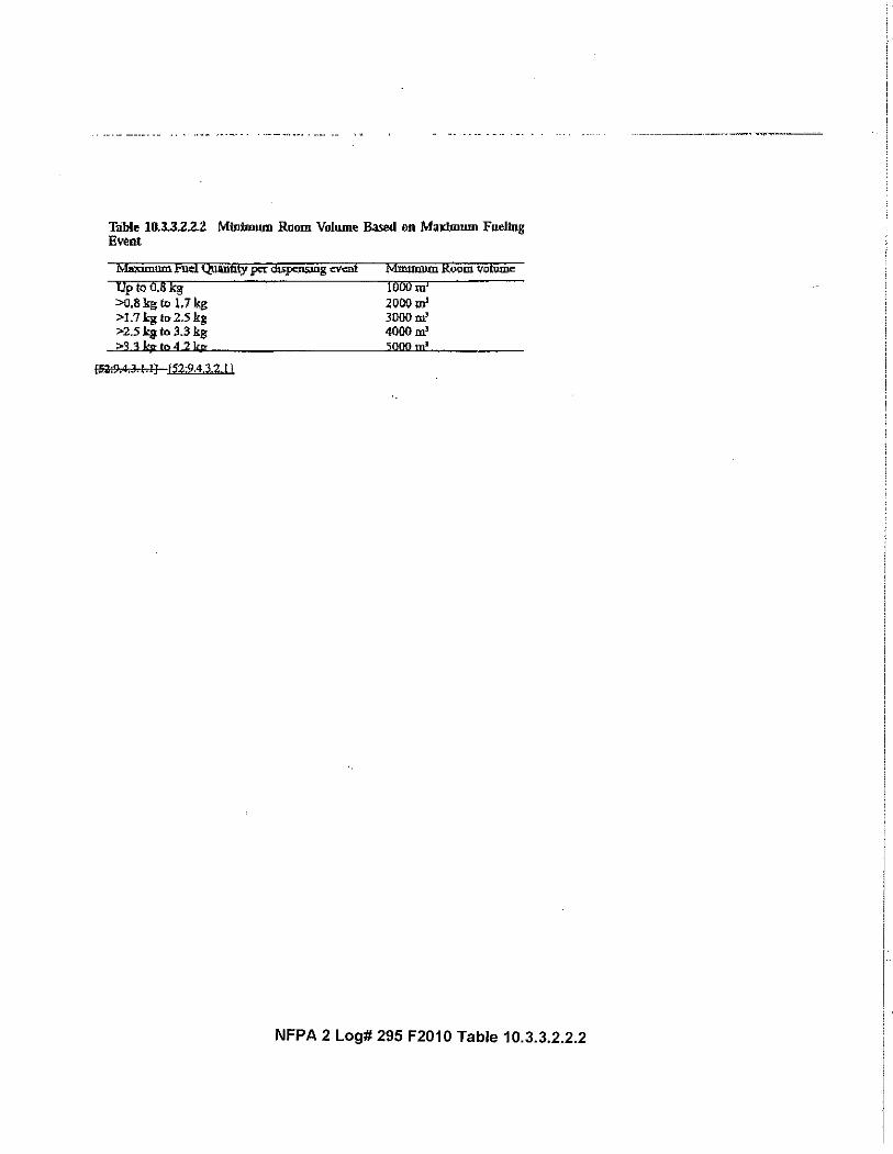
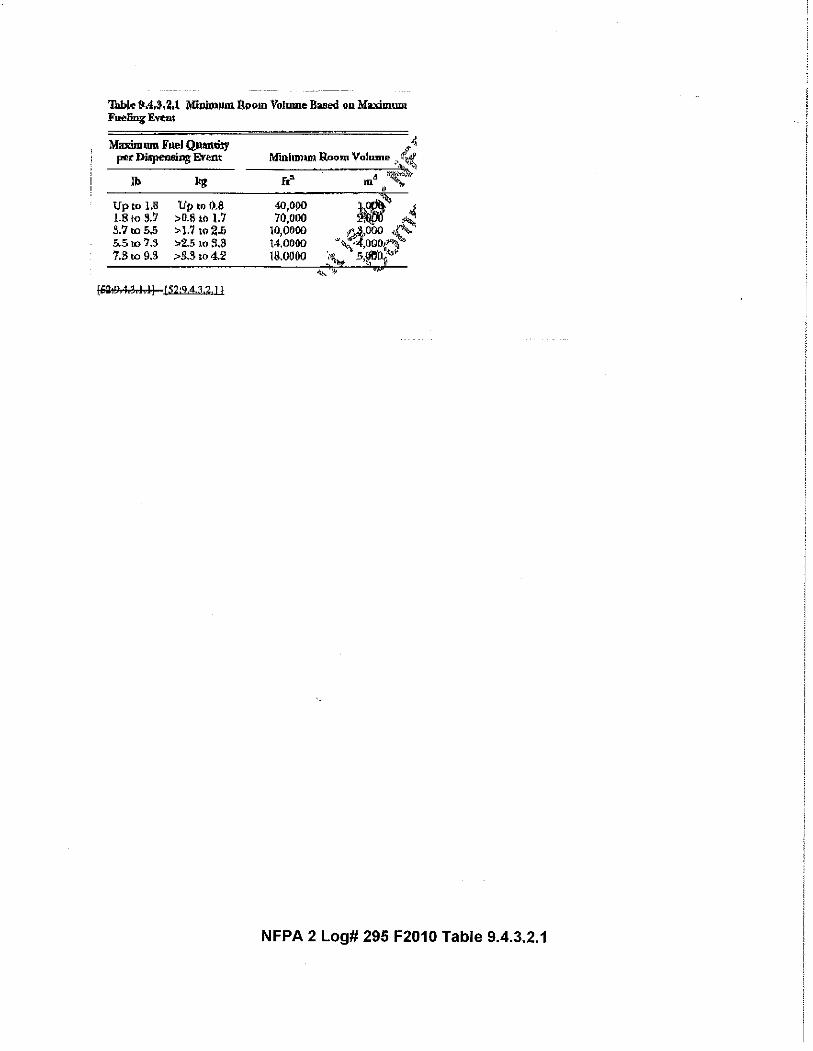
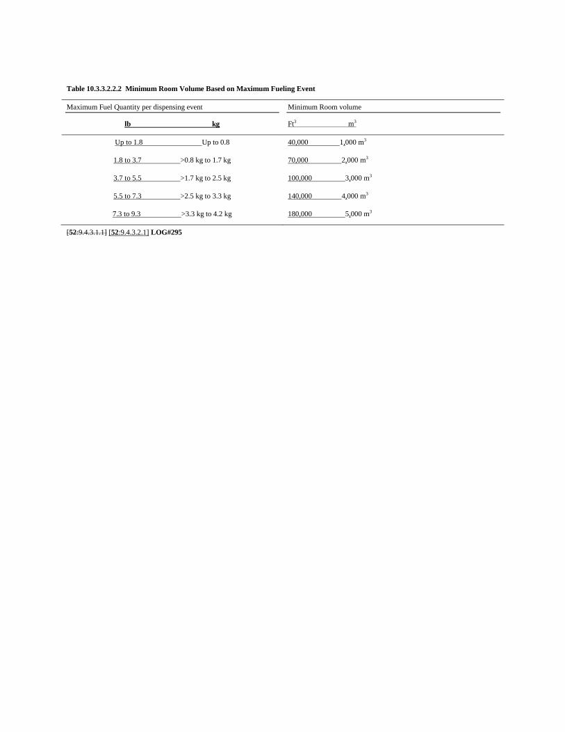
Table 10.3.3.2.2.2 Minimum Room Volume Based on Maximum Fueling Event
Maximum Fuel Quantity per dispensing event
lb kg
Minimum Room volume
Ft3 m3
Up to 1.8 Up to 0.8 40,000 1,000 m3
1.8 to 3.7 >0.8 kg to 1.7 kg 70,000 2,000 m3
3.7 to 5.5 >1.7 kg to 2.5 kg 100,000 3,000 m3
5.5 to 7.3 >2.5 kg to 3.3 kg 140,000 4,000 m3
7.3 to 9.3 >3.3 kg to 4.2 kg 180,000 5,000 m3
[52:9.4.3.1.1] [52:9.4.3.2.1] LOG#295

Report on Comments – November 2010 NFPA 2_______________________________________________________________________________________________2-213 Log #134
_______________________________________________________________________________________________Larry L. Fluer, Fluer, Inc. / Rep. Compressed Gas Association
2-1Revise text to read as follows:
Shutdown. Actuation or failure of the following systems shall automatically shut down the gas flow from thedispenser, stop the flow of gas to the room, and start or continue to run the mechanical ventilation system [whenmechanical ventilation systems are required]. [ :9.4.7.3]Also, revise paragraph (E) as follows:
Gas Detection System. The dispenser enclosure or housing shall be equipped with a gas detection system whichshall actuate when a maximum of 25% of the lower flammable limit (LFL) is detected (1% H2 in air). [ :9.4.7.4]
(1) Actuation of the gas detection system shall shut down the dispenser, stop the flow of gas into the room, and startor continue to run the ventilation system [when required]. [ :9.4.7.4.1]
(2) Actuation of the gas detection system shall sound a local alarm and provide visual indication when a maximum of25% of the lower flammable limit (LFL) is detected (1% H2 in air). [ :9.4.7.4.2]
(3) The gas detection system shall function during maintenance operations on the ventilation system. [ :9.4.7.4.3]Section 10.3.3.2.2.2 does not require mechanical ventilation systems in cases where the area meets
the requirements of that subsection and the maximum fueling event is limited. Item (6) of 10.3.3.2.2.7(C) indicates thatonly required ventilation systems are affected, however, the charging language in the paragraph is not clear in thisregard. A similar problem exists in item (E)(1) of this subsection. Although Item (3) mentions ventilation, adding“required” is not necessary in this section.
_______________________________________________________________________________________________2-214 Log #290
_______________________________________________________________________________________________Nancy C. Pehrson, CenterPoint Energy, Inc.
2-1Revise text as follows:
Extract the entire Section 9.3.3 Indoors from NFPA 52 or reference 10.3.2.1.1Extracted material from NFPA 52 would apply to indoor fleet (non-public) or public fueling. NFPA 52
does not have differing requirements for indoor fueling for public or non-public use – only for the speed of fueling(different requirements for fast-fill) or use of Vehicle Fueling Appliances.
NFPA 52 has (1) general indoor dispensing requirements (9.3.3), (2) indoor fast-fill fueling requirements (9.4) whichinclude qualified operator, and (3) indoor fueling requirements using a Vehicle Fueling Appliance in NonresidentialOccupancies (9.17). Using a residential Fueling Facility (RFF-GH2) indoors is currently reserved in NFPA 52 (9.18.5.2).
Indoor Non Public Slow Fill Fueling adheres to the same requirements as Indoor Public Dispensing Fueling GeneralSection 10.3.2.2.1 which is extracted from 9.3.3 Indoors from NFPA 52.
Better descriptive should be used for this section. Extracted sections 10.3.2.1.1, and 10.3.2.1.1.2 from NFPA 52Sections 9.3.1.1 and 9.3.1.2 apply for indoor or outdoor applications and not just to dispensing to the public.
Copy 10.3.2.1.1, 10.3.2.1.1.1, and 10.3.2.1.1.2 from the NFPA 2 ROP Draft and insert them into Section 10.3.3.2.This log was not submitted in legislative format so the intent is not clear. The Committee does
not recommend removing Reserved from 2:10.3.3.2.3 at this time. The Committee believes that the sections that arecopied meets the intent of the Proponent. The Committee does not want to apply all the provisions of indoor, fast-fillinstallations to indoor, slow-fill installations at this time.
115Printed on 6/1/2010
Report on Comments – November 2010 NFPA 2_______________________________________________________________________________________________2-215 Log #136
_______________________________________________________________________________________________Larry L. Fluer, Fluer, Inc. / Rep. Compressed Gas Association
2-11. Relocate Section 10.3.3.2.4.1 to a new Section 10.3.3.2.1.1(G) and (H) as follows:
Where installed indoors in public assembly and educational occupancies, a VFA shall be located in aportion of the occupancy where 101, , or the local building code permits the installation ofhazardous equipment. [ :9.17.5]
[ :9.17.5]VFAs shall not be installed within 10 ft (3.0 m) of any flammable gas or liquid storage. [ :9.17.6]
[ :9.17.6]2. Relocate 10.3.3.2.4.2 to 10.3.3.4.2 as a new Section (E) and renumber the following sections.
Installation of pressure relief valves shall have pressure relief device vents or vent lines to conveyescaping gas to the outdoors and then upward to a safe area to prevent impinging on buildings, other equipment, orareas open to the public, such as sidewalks. [ :9.18.6]3. Revise the title of 10.3.3.2.4 as follows:
Section 10.3.2.4.1 has been incorrectly located in Chapter 10. Educational occupancies include anoccupancy used for educational purposes through the twelfth grade by six or more persons for 4 or more hours per dayor more than 12 hours per week. Educational occupancies include kindergartens, academies, and schools (generally Kthrough 12). Assembly occupancies include an occupancy (1) used for a gathering of 50 or more persons fordeliberation, worship, entertainment, eating, drinking, amusement, awaiting transportation, or similar uses; or (2) usedas a special amusement building, regardless of occupant load.
It could be that the concept of allowing hazardous equipment are those identified in Section 8.7.1 ofNFPA 101 as an area requiring special protection. However, Section 8.7.3.1 references flammable gases and liquidsin conformance with NFPA 54 National Fuel Gas Code, NFPA 58 Liquefied Petroleum Gas Code, and NFPA 30Flammable and Combustible Liquids Code. Hydrogen is not regulated by NFPA 54.
116Printed on 6/1/2010
Report on Comments – November 2010 NFPA 2_______________________________________________________________________________________________2-216 Log #291
_______________________________________________________________________________________________Nancy C. Pehrson, CenterPoint Energy, Inc.
2-1Revise text as follows:
Extract Sections 9.11.1.1 – 9.11.3, 9.11.5 – 9.11.7 and 9.11.9., 9.14.1.2 – 9.15.2 from NFPA 52 or refer to appropriateextracted sections extracted from NFPA 52 in Chapter 10
Extract Section 9.11.8 from NFPA 52 or refer to appropriate extracted sections extracted from NFPA 52 in Chapter 10
Extract 9.17.1 – 1.17.4, 9.17.6 from NFPA 52 or refer to appropriate extracted sections extracted from NFPA 52 inChapter 10
Extracted material from NFPA 52 would apply to outdoor fleet (non-public) or public fueling. NFPA 52does not have differing requirements for outdoor fueling for public or non-public use – only for the speed of fueling(different requirements for fast-fill) or use of Vehicle Fueling Appliances.
Reservation of these non-public outdoor fueling sections are confusing as to whether fleet or nonpublic fueling iscovered.
NFPA 52 has (1) general outdoor dispensing requirements (9.11.1.1 – 9.11.3, 9.11.5 – 9.11.7 and 9.11.9., 9.14.1.2 –9.15.2), (2) outdoor fast-fill fueling requirements (9.11.8) and (3) outdoor fueling requirements using a Vehicle FuelingAppliance in Nonresidential Occupancies (9.17.1 – 9.17.4.3, 9.17.6).
NFPA 52 allows for Vehicle Fueling Appliances to be used in Nonresidential occupancies for non-public fueling (fleets)
Remove Reserve from 10.3.3.3.1 and add the following text:Outdoor, non-public fueling installations shall meet the requirements of 10.3.2.3.1.
This log was not submitted in legislative format so the intent is not clear. The Committee doesnot recommend removing Reserved from 2:10.3.3.3.2 and 10.3.3.3.3 at this time. The Committee believes that thesections that are referenced meets the intent of the Proponent.
117Printed on 6/1/2010

Report on Comments – November 2010 NFPA 2_______________________________________________________________________________________________2-217 Log #137
_______________________________________________________________________________________________Larry L. Fluer, Fluer, Inc. / Rep. Compressed Gas Association
2-45Insert a new Section 10.3.3.3.4.2 and renumber existing 10.3.3.4.2 as 10.3.3.3.4.3.
The RFF-GH2 shall store GH2 indoors or outdoors. Indoor storage of GH2 shall not exceed 6000 psi (41.4MPa) and shall be ventilated per 9.3.3.5, or contained in a separate sealed enclosure ventilated directly to outdoors.[ 9.18.2.1]
Sections 9.18.2 and 9.18.2.1 were not extracted from NFPA 52. NFPA 52 Section 9.18.2 requires thatGH2 storage systems be “listed” by a Nationally Recognized Testing Laboratory, and it has not been proposed forextraction into NFPA 2. There is no known listing standard, and the variability in these systems is such that listingbecomes questionable. In addition, storage systems are under the purview of NFPA 55 and requirements for listing byNFPA 52 for storage systems is questionable. Regarding 52:9.18.2.1, NFPA 52’s technical committee in deliberatingRFF fueling systems determined that the use of such systems would be limited to use outdoors.
NFPA 52 ROP item 52-36 Log #18 to insert the requirements for the use of Residential Fueling Facilities into NFPA 52,including these two sections, was accepted in principle by the Technical Committee. The committee statement as itappeared in the ROP was as follows:
Note that the intent of the TC was to exclude residential fueling facilities indoors until such time as the requirementswere fully developed. For example, the NFPA 52 TC did not address ventilation in residential occupancies in a fashionsimilar to that done in the I-Codes including the IMC and IRC based on studies conducted by Dr. Swain. Establishing arequirement for allowing storage systems indoors while prohibiting the use of RFFs indoors is not logical. Requirementsfor storage of hydrogen at any pressure in indoor residential occupancies is in need of further work to ensure that thetypes of facilities in which these units may be installed are provided with a design that will allow for the safe storage ofthese materials.
Establishing a requirement that requires the storage of hydrogen to be outside of residential buildings is in concert withexisting 10.3.3.3.4.2(C)(1) (currently incorrectly numbered as 10.3.3.4.2) which requires such equipment to be installedoutdoors.
118Printed on 6/1/2010
Report on Comments – November 2010 NFPA 2_______________________________________________________________________________________________2-218 Log #138
_______________________________________________________________________________________________Larry L. Fluer, Fluer, Inc. / Rep. Compressed Gas Association
2-1Revise text to read as follows:
An RFF-GH2 shall be operated in accordance with the instructions of the manufacturer. [ :9.18.10](1) A fuel supply container shall not be charged in excess of its maximum allowable service pressure at
normal temperature. [ :9.18.10.1](2) DOT and TC containers shall be charged in accordance with DOT and TC regulations. [ :9.18.10.2](3) Where GH2 is being transferred to a motor vehicle, the engine shall be turned off. [ :9.18.10.3]
Item (3) of Subsection (H) of 10.3.3.3.4.2 was included in the Word version of the NFPA 2 ROP,however, it was not carried to the PDF file for some reason. The paragraph regarding the shutdown of the motor vehiclebeing fueled remains applicable and it should be included to maintain the intent of this section.
_______________________________________________________________________________________________2-219 Log #56
_______________________________________________________________________________________________David J. Farese, Air Products and Chemicals, Inc.
2-1Revise text to read as follows:
(E) Testing. All piping and tubing shall be tested after assembly according to 10.3.1.11 10.3.1.1.10.Note also that references within NFPA 52, 2010 also is an incorrect paragraph and should be 9.10 instead of 9.9.1.4 as
indicated below.9.18.8.1 All piping and tubing shall be tested after assembly according to 9.9.1.4.
The reference paragraph is incorrect. This proposal corrects the reference. This proposal is part of theresult of NFPA 52 Task Group efforts.
_______________________________________________________________________________________________2-220 Log #156
_______________________________________________________________________________________________Thomas J. Forsythe, Hughes Associates, Inc.
2-1Recommend correcting extraction to the exact text from 52: 9.3.3.2* with exception:
Bulk hydrogen compressed gas systems shall be in accordance with NFPA 55,.
The extraction has not been properly accomplished. This proposal corrects errors in the extraction.This proposal is part of the result of NFPA 52 Task Group efforts.
The relevant requirements of NFPA 55 are already in Chapters 6 and 7. The reference to referto NFPA 55 in NFPA 2 would be redundant. 10.4.2.1 is not marked as an extract and, therefore, the requirement doesnot need to match what is in NFPA 52.
119Printed on 6/1/2010
Report on Comments – November 2010 NFPA 2_______________________________________________________________________________________________2-221 Log #CC7
_______________________________________________________________________________________________Technical Committee on Hydrogen Technology,
2-45Delete 10.4.2.2 Storage of GH2 in Indoor Residential Fueling Facilities (RFF) in its entirety.
The provisions surrounding the indoor storage of hydrogen in residential fueling facilities is incomplete.Deleting this material is consistent with the actions taken in 2-217 (Log #137).
_______________________________________________________________________________________________2-222 Log #42
_______________________________________________________________________________________________Mark Richards, Versa Power Systems
2-51New text to read as follows
10.14.1.1 A vehicle container shall not be subjected to pressure in excess of 125 percent of the marked servicepressure even if, on cooling, the pressure settles to the marked service pressure.
Please withdraw my proposal and in its place add the above clause. Container standards allows fortransient overfilling to 125% of market service pressure so that a full fill can be realized upon cooling of the gas thatheats up during the fueling process. The language in the comment above is based on NFPA 52 8.14.1.2 for CNG. Thesame thermodynamic principles apply to compressed hydrogen fueling and NFPA 52, failed to bring the requirement of8.14.1.2 into its hydrogen chapter in 9.14.1.
Insert 10.3.1.14.1.1 as follows:A vehicle fuel container shall not be subjected to pressure in excess of 125 percent of its marked service
pressure.This log was not submitted in legislative format so the intent is not clear. The Proponent is
referring to 2:10.3.1.14.1 not 2:10.14.1 and 10.14.2. The Proponent’s substantiation has technical merit and theCommittee believes that this issue is not adequately addressed in NFPA 52.
120Printed on 6/1/2010
Report on Comments – November 2010 NFPA 2_______________________________________________________________________________________________2-223 Log #206
_______________________________________________________________________________________________Larry L. Fluer, Fluer, Inc. / Rep. Compressed Gas Association
2-53Revise text to read as follows:
Reorganize the major structure of Chapter 11 to provide a closer correlation with the structure of Chapter 10 to addressthe area of public vs. private fueling including conditions of full service attended fueling, self service attended andunattended fueling. Correlate the terminology used for each of the major section headings with Chapter 10. The actualtext may vary, but there should be a consistency between the two chapters.
*****Insert 2_L206_Tbl Chapter 11_R******
The format used in Chapter 11 should be mirrored against that used in Chapter 10. If conditions ofpublic vs. nonpublic fueling are to be addressed for LH2 Sections the structure needs to be expanded. Chapter 11could be restructured to address the concept of public vs. non-public fueling to correlate with the approach taken inChapter 10. There are a reduced number of sections as 11.3.2 prohibits indoor fueling with LH2. Reformat the Chapterinto the following major subsections and renumber and reorganize the content as follows. After the framework isestablished there may be a number of sections where the action is prohibited until the technology matures, or thesection may simply be reserved. This comment is a placeholder pending action at the ROC meeting.
121Printed on 6/1/2010

2_L206_Tb for Chapter 11_RecF2010 ROC 1
Section Title Comment
11.1 Scope
11.2 General
11.3 Dispensing Correlate by Changing 10.3 to Dispensing
11.3.1 General
11.3.2 Indoor Fueling Change to Dispensing to the Public
11.3.3 Outdoor Public Fueling Change to Outdoor Public Fueling
11.3.3.1 General
11.3.3.3
11.3.3.2
Outdoor Public Full Service
Attended Fueling
11.3.3.4
11.3.3.3
Outdoor Public Attended Self
Service Fueling
11.3.3.5
11.3.3.4
Outdoor Public Unattended Self
Service Fueling
11.3.4 Outdoor Non-Public Fueling
11.3.4.1 General
11.3.4.2 Outdoor Non-Public Full Service
Fueling
11.3.4.3 Outdoor Non-Public Attended
Self Service Fueling
11.3.4.4 Outdoor Non-Public Unattended
Self Service Fueling
11.3.4.5 Outdoor Non-Public Residential
Fueling
The only requirement may be a prohibition.
11.3.3.2
11.3.4.6
Refueling from Transport
Vehicles
11.4 Storage
11.4.1 General
11.4.2 Indoor Storage
11.4.3 Outdoor Storage
11.4.4 Underground Storage

Report on Comments – November 2010 NFPA 2_______________________________________________________________________________________________2-224 Log #270
_______________________________________________________________________________________________Robert M. Burgess, National Renewable Energy Laboratory
2-53Revise text to read as follows:
The following systems and system components shall be listed orapproved: [ :5.2.1]
(1) Pressure relief devices, including pressure relief valves [ 5.2.1](2) Pressure gauges [ 5.2.1](3) Pressure regulators [ 5.2.1](4) Valves [, fittings and tubing] [ 5.2.1](5) Hose and hose connections [ 5.2.1](6) Vehicle fueling connections (nozzle) [ 5.2.1](7) Metal hydride storage [ 5.2.1](8) Electrical equipment used with GH2 [LH2] systems [ 5.2.1](9) Gas detection equipment and alarms [ 5.2.1](10) Hydrogen generators [liquefier] [ 5.2.1](11) Hydrogen dispensers [ 5.2.1](12) Pressure switches [ 5.2.1](13) Flow meters [ 5.2.1](14). Composite storage (reserved)
Pressure relief valves for GH2 LH2 service shall not be fitted with lifting devices. [ 5.4.6]The adjustment, if external, shall be provided with a means for sealing the adjustment to prevent
tampering. [ 5.4.6.1]If at any time it is necessary to break such a seal, the valve shall be removed from service until it has
been reset and sealed. [ 5.4.6.2]Adjustments shall be made only by the manufacturer or other companies having competent personnel
and facilities for the repair, adjustment, and testing of such valves. [ 5.4.6.3]The organization making such adjustment shall attach a permanent tag with the setting, capacity, and
date. [ 5.4.6.4]Pressure relief valves protecting ASME pressure vessels shall be repaired, adjusted, and tested in
accordance with the ASME Boiler and Pressure Vessel Code. [ 5.4.7]All discharges from pressure relief devices serving the fueling system shall be connected to a vent system and
direct the vented product to a safe location.A pressure relief device must be installed on all sections of piping where liquid or cold gas can be trapped
between valves.
Pipe, tubing, and fittings shall be suitable for hydrogen service and for maximum pressures and minimumand maximum temperatures. [ 5.8.1]
Pipe, tubing, fittings, gaskets, and packing material shall be compatible with the fuel under serviceconditions. [ 5.8.1.1]
Gray, ductile, and cast iron pipe and fittings shall not be used. [ 5.8.1.2]Pipe, tubing, fittings, and other components shall be designed with a minimum safety factor of 3. [ 5.8.2]Hydrogen gas piping shall be fabricated and tested in accordance with ANSI/ASME B31.3, .
[ 5.8.3]Piping joints made with tapered threaded pipe and sealant shall not be used downstream of the source
valve in hydrogen service above 3000 psi (20.7 MPa). [ 5.8.4.1]Tapered joints are allowed on systems exceeding 3000 psi (20.7 MPa) under the following conditions:
[ 5.8.4.2](1) Where valves or instrumentation are not available with straight threads, or [ 5.8.4.2(1)](2) Where tapered joints are seal welded in accordance with the requirements of ANSI/ASME B31.3,
122Printed on 6/1/2010

Report on Comments – November 2010 NFPA 2.[ 5.8.4.2(2)]
Piping components such as strainers, snubbers, and expansion joints shall be permanently marked by themanufacturer to indicate the service ratings. [ 5.8.5]
Piping and hose shall be run as directly as practical and with provisions to protect the piping from theeffects of expansion, contraction, jarring, vibration, and settling. [ 9.9.1]
Exterior piping shall be either buried, laid in a trench, or installed above ground and shall be supportedand protected against mechanical damage. [ 9.9.1.1]
Manifolds connecting fuel containers shall be fabricated to minimize vibration and shall be installed in aprotected location or shielded to prevent damage from unsecured objects. [ 9.9.1.4.1.1]
A pipe thread jointing material impervious to the action of the hydrogen used in system shall be applied toall male pipe threads prior to assembly. [ 9.9.1.4.1.2]
Threaded piping and fittings shall be clear and free from cutting or threading burrs and scales, and theends of all piping shall be reamed. [ 9.9.1.4.1.3]
Threaded pipe and fittings shall not be used underground. [ 9.9.1.4.1.4]Piping joints made with tapered threaded pipe and sealant shall not be used in hydrogen service.
[ 9.9.1.4.2]A bend in piping or tubing shall have the pressure rating reduced according to ANSI/ASME B31.3,. [ 9.9.1.4.3]Joints or connections shall be located in an accessible location. [ 9.9.1.4.4]The number of joints shall be minimized and placed in a location considering personnel safety.
[ 9.9.1.4.5]Hydrogen shall be vented in accordance with Section 6.16. [ 9.9.2]
Hose, metallic hose, flexible metal hose, tubing, and their connections shall be designed or selected for themost severe pressures and temperatures expected under normal operating conditions with a burst pressure of at leastthree times the MAWP. [ 5.10.2]
Prior to use, hose assemblies shall be tested by the component OEM or its designated representative at apressure at least twice the maximum allowable pressure. [ 5.10.3]
Hose and metallic hose shall be distinctly marked by the manufacturer, either by the manufacturer'spermanently attached tag or by distinct markings indicating the manufacturer's name or trademark, applicable serviceidentifier, design pressure, and flow direction. [ 5.10.4]
The use of hose in an installation shall be limited to the following: [ 9.9.3]Vehicle fueling hose [ 9.9.3]
Hose shall be constructed of or lined with materials that are resistant to corrosion and exposure tohydrogen. [ 5.10.1]
Hose, metallic hose, flexible metal hose, tubing, and their connections shall be designed or selected for themost severe pressures and temperatures expected under normal operating conditions with a burst pressure of at leastthree times the MAWP. [ 5.10.2]
Prior to use, hose assemblies shall be tested by the component OEM or its designated representative at apressure at least twice the maximum allowable pressure. [ 5.10.3]
Hose and metallic hose shall be distinctly marked by the manufacturer, either by the manufacturer'spermanently attached tag or by distinct markings indicating the manufacturer's name or trademark, applicable serviceidentifier, design pressure, and flow direction. [ 5.10.4]
The use of hose in an installation shall be limited to the following: [ 9.9.3]Vehicle fueling hose [ 9.9.3]
Valves, valve packing, and gaskets shall be designed or selected for the fuel over the full range ofpressures and temperatures to which they can be subjected under any operating conditions. [ 5.9.1]
Shutoff valves shall have a rated service pressure not less than the rated service pressure of the entiresystem and shall be designed with a minimum safety factor of 3. [ 5.9.1.1]
Leakage shall not occur when tested to at least one-and-a-half of the rated service pressure, using aninert gas as the test medium. [ 5.9.1.2]
Valves of a design that allows the valve stem to be removed without removal of the complete valve bonnet
123Printed on 6/1/2010

Report on Comments – November 2010 NFPA 2or without disassembly of the valve body shall not be used. [ 5.9.2]
The manufacturer shall stamp or otherwise permanently mark the valve body to indicate the service ratings.
[ 5.9.3]
Piping, tubing and hose, and hose assemblies shall be leak tested after assembly to prove them free fromleaks at a pressure equal to at least the normal service pressure of that portion of the system. [ 9.10.1]
This leak test shall be in addition to the ANSI/ASME B31.3, testing required by 7.1.5.5.[ 9.10.1.1]
The assembly shall be leak tested using hydrogen or helium. [ 9.10.1.2]Where hydrogen is to be used as the leak test media, the system shall first be purged with an inert gas to
ensure that all oxygen is removed. [ 9.10.1.3]Pressure relief valves shall be tested at least every 3 years. [ 9.10.2]At fueling stations, gas used for calibration and testing shall be vented to a vent pipe in accordance with
Section 6.16. [ 9.9.5]
Hoses, nozzles, and breakaways shall be examined according to the manufacturers' recommendationsor at least monthly and shall be maintained in accordance with the manufacturers' instructions. [ 9.16.2.1]
Hose shall be tested for leaks per manufacturer's requirements, and any unsafe leakage or surfacecracks shall be reason for rejection and replacement. [ 9.16.2.2]
Testing shall be carried out using an inert gas as the test medium. [ 9.16.2.3](A) Where this is not possible, the hose assembly shall be completely isolated from the system and tested with the
flammable gas normally within the system, or with air and then purged with an inert gas. [ 9.16.2.3.1](B) In the case of hydrogen, testing shall be carried out with helium or a helium inert gas blend (10 percent by volume
or greater) as the test gas or if this is not possible, with hydrogen using suitable precautions. [ 9.16.2.3.2]Controllers on fuel stations shall be designed to verify the integrity of the fuel hose, breakaway, nozzle,
and receptacle by pressurizing these components to at least the vehicle back pressure and checking pressure drop overa period of at least 5 seconds prior to the start of fueling. [ 9.16.2.6]
A portable fire extinguisher having a rating of not less than 20-B:C shall be provided at the dispensing area inapproved locations not more than 50 feet (15.25 meters) away from the dispensing area. Fire extinguishers shall beinspected and maintained according to NFPA 10 [ 9.15]
Dispensing equipment shall be provided with gas detectors, leak detection, and flame detectors such thatfire and gas can be detected at any point on the equipment. 9.2.14
These detectors shall be maintained and calibrated in accordance with the manufacturer's instructionson at least an annual basis or earlier if required by the manufacturer. [ 9.2.14.1]
The station owner or operator shall maintain a record of detector maintenance and calibration in goodcondition and accessible to the inspector. [ 9.2.14.2]
A sticker at least 6 in.2 (39 cm2) shall be affixed on the dispenser indicating the date of the nextscheduled maintenance and calibration. [ 9.2.14.3]
A vehicle fueling pad shall be provided in the area where vehicles are to be refueled.The vehicle fueling pad shall be of concrete or other non-combustible surface. Asphalt and similar materials
are not permitted.The pad shall be constructed with a length and width to accommodate the types of vehicles to be fueled
and to provide a surface under the fueling hoseChapter 10 requirements need to be added to Chapter 11
The committee has resolved these actions with 2-234 (Log #185), 2-242 (Log #189), 2-244(Log #192), 2-245 (Log #193), 2-246 (Log #143), 2-247 (Log #186), 2-248 (Log #187), 2-249 (Log #188), 2-261 (Log#201), and 2-262 (Log #202).
124Printed on 6/1/2010

Report on Comments – November 2010 NFPA 2_______________________________________________________________________________________________2-225 Log #158
_______________________________________________________________________________________________Thomas J. Forsythe, Hughes Associates, Inc.
2-1NFPA 52 'Application' is presented as NFPA 2 chapter 11 Scope with additional application
sections. Recommend deletion of 2: 11.1.1:This chapter shall apply to the storage, use, and handling of LH2 in connection with self-propelled
vehicles powered by GH2 or LH2.”The extraction has not been properly accomplished. This proposal corrects errors in the extraction.
This proposal is part of the result of NFPA 52 Task Group efforts.
The committee felt that this comment would reject the charging language required for NFPA 2.The committee believes that 2-226 (Log #144) already addresses this.
_______________________________________________________________________________________________2-226 Log #144
_______________________________________________________________________________________________Larry L. Fluer, Fluer, Inc. / Rep. Compressed Gas Association
2-53Revise the following three sections:
. This chapter shall apply to the storage, use, and handling of LH2 in connection with self-propelledvehicles powered by hydrogen GH2 or LH2.
The storage, use, and handling of LH2 in connection with self-propelled vehicles powered by hydrogen GH2or LH2shall also comply with the requirements of Chapters 1 through 4 and the applicable requirements of Chapters 5through 8.
The requirements of Chapter 11 shall be applicable to LH2 systems only. When LH2 is converted to GH2,those portions of the system utilized for GH2 shall be in accordance with Chapter 10. [14.12.1]
The scope of Chapter 11 is limited to fueling with LH2. The change of phase from LH2 to GH2 is notconsidered within the context of fueling even though this may occur as the material is transformed from liquid to gas.NFPA 52 Chapter 14 Section 14.1, in pertinent part, applies to the “storage and dispensing of LH2 as an engine fuel forvehicles of all types.” The term GH2 is not used. NFPA 52 Section 14.12 mentions the conversion of LH2 to GH2, butrefers the user back to Chapter 9 for requirements. Clearly, the inclusion of GH2 in NFPA 2 Chapter 11 is not in concertwith the scope, and references throughout Chapter 11 should be removed where conflict occurs.Section 11.1.1.3 was partially extracted from 52:14.12.1. It should be reconstituted to reflect the extract concept as it isin accord with NFPA 52 in this regard.
125Printed on 6/1/2010

Report on Comments – November 2010 NFPA 2_______________________________________________________________________________________________2-227 Log #271
_______________________________________________________________________________________________Robert M. Burgess, National Renewable Energy Laboratory
2-53Revise text to read as follows:This chapter shall apply to the storage, use, and handling of LH2 in connection with hydrogen
vehicle fueling.self-propelled vehicles powered by GH2 or LH2.The storage, use, and handling of LH2 in connection with hydrogen vehicle fueling. self propelled vehicles
powered by GH2 or LH2 shall also comply with the requirements of Chapters 1 through 4 and the applicablerequirements of Chapters 5 through 8.
The installation and use of CNG [and hydrogen] systems shall meet the requirements of NFPA 52,[, except as modified by this chapter]. The installation and use of LNG systems shall meet the
requirements of NFPA 52, [, except as modified by this chapter]. The installation and useof LP-Gas systems shall meet the requirements of NFPA 58, [, except as modified by thischapter]. [ 12.2.1]
Clarification, this chapter is use specific to LH2 fueling. Reference to GH2 and to vehicles ismisleading. Similarly, section 11.1.1.4 is not applicable to LH2 fueling.
Delete the text to read as follows and make no other changes:The installation and use of CNG [and hydrogen] systems shall meet the requirements of NFPA 52,
[, except as modified by this chapter]. The installation and use of LNG systems shall meet therequirements of NFPA 52, [, except as modified by this chapter]. The installation and useof LP-Gas systems shall meet the requirements of NFPA 58, [, except as modified by thischapter]. [ 12.2.1]
See 2-226 (Log #144), which already changed 11.1.1 and 11.1.1.1.
126Printed on 6/1/2010

Report on Comments – November 2010 NFPA 2_______________________________________________________________________________________________2-228 Log #183
_______________________________________________________________________________________________Glenn Mahnken, FM Global
2-1Add new text as follows:
All hydrogen refueling station sites shall have a complete HAZOP or process safety analysisprior to dispensing fuel. [ 14.3.1]
The hazard analysis and all supporting documentation, including schematics and drawings, shall besubmitted to the AHJ for Approval.
An Approved copy of the hazard analysis and supporting documentation shall be kept on file on site for thelife of the installation
The hazard analysis shall be updated and re-submitted to the AHJ for Approval whenever the installation ismodified.
The additional requirements will help ensure that the Hazards Analysis is accessible and updated overthe life of the installation.
Revise the suggested text as follows:All hydrogen refueling station sites shall have a complete HAZOP or process safety analysis
prior to dispensing fuel. [ 14.3.1]The hazard analysis shall be updated when changes to the process affect operating limits or design
specifications that were included as the basis for the original hazard analysis.The committee wanted to establish a management of change requirement as applicable to the
hazards analysis. The proposed modifications accomplish the proponent's intent. The other text was not acceptedbecause it was not needed.
_______________________________________________________________________________________________2-229 Log #159
_______________________________________________________________________________________________Thomas J. Forsythe, Hughes Associates, Inc.
2-1Recommend correcting extraction to the exact text from 52: 14.3.1.5 ('refueling' has been
substituted for 'fueling'):LH2 refueling fueling sites utilizing or dispensing LH2 shall provide personnel protection
barriers such as walls, cabinets, vacuum jacketed pipe and similar barriers to protect the refueling operator and thevehicle being fueled from contact with a release of LH2. All facility piping other than the refueling line to the vehicle shallbe behind the barrier, to deflect any LH2 that is released due to an equipment malfunction. [ 14.3.1.5]”
The extraction has not been properly accomplished. This proposal corrects errors in the extraction.This proposal is part of the result of NFPA 52 Task Group efforts.
The NFPA 2 provision has been extracted from the 2010 edition in its existing form.
127Printed on 6/1/2010

Report on Comments – November 2010 NFPA 2_______________________________________________________________________________________________2-230 Log #190
_______________________________________________________________________________________________Larry L. Fluer, Fluer, Inc. / Rep. Compressed Gas Association
2-53Revise text to read as follows:
Smoking materials, including matches and lighters, shall not be used within [25 ft] (7.6 m)[20 ft (6 m)] of areas used for fueling, servicing fuel systems of internal combustion engines, or receiving or dispensingof [LH2] [Class I and Class II liquids]. The motors of all equipment being fueled shall be shut off during the fuelingoperation except for emergency generators, pumps, [pagers], and so forth, where continuing operation is essential.[ 9.2.5.1]
The distance limitation developed for keeping ignition sources to a distance of 20 ft from liquid fuels isincongruous with the distances developed for hydrogen throughout NFPA 2. Section 4.14.3 and others require adistance of 25 ft separation from storage as well as dispensing systems. In addition, a distance of 25 ft is consistentwith requirements for electrical classification as noted in Table 11.2.16.1.
_______________________________________________________________________________________________2-231 Log #272
_______________________________________________________________________________________________Robert M. Burgess, National Renewable Energy Laboratory
2-53Revise text to read as follows:
Smoking materials, including matches and lighters, shall not be used within [20 25] ft (6 m)of areas used for fueling, servicing fuel systems of internal combustion engines, or receiving or dispensing of [hydrogen][Class I and Class II liquids]. The motors of all equipment being fueled shall be shut off during the fueling operationexcept for emergency generators, pumps, [pagers], and so forth, where continuing operation is essential. [ 9.2.5.1]
Smoking materials, including matches, lighters, and other sources of ignition, including torches, shall not beused within [20 25] feet (6.1 meters) of the dispensing of LH2 in the open from a transport vehicle to a motor vehicle.[ 14.17.4]
Change to NFPA 30A and NFPA 52 text. Change 20’ to 25’ to be consistent with electricalclassification.
_______________________________________________________________________________________________2-232 Log #191
_______________________________________________________________________________________________Larry L. Fluer, Fluer, Inc. / Rep. Compressed Gas Association
2-28, 2-53Delete the following text:
Where required, automatic fire suppression systems shall be installed inaccordance with the appropriate NFPA standard, manufacturers’ instructions, and the listing requirements of thesystems. [ 9.2.5.3]
Section 11.2.10 is redundant to the requirements of Chapter 6. Fire protection systems are the subjectof 6.10 which is triggered by 11.1.1.1. Fueling with LH2 indoors is prohibited by 11.3.2. If sprinklers are providedbeneath canopies Section 6.10.1 would prevail. The practice in a gas fire, especially one involving LH2 is to shut off thesource of the gas.
128Printed on 6/1/2010

Report on Comments – November 2010 NFPA 2_______________________________________________________________________________________________2-233 Log #273
_______________________________________________________________________________________________Robert M. Burgess, National Renewable Energy Laboratory
2-53Revise text to read as follows:
Where required, automatic fire suppression systems shall be installed inaccordance with the appropriate NFPA standard, manufacturers’ instructions, and the listing requirements of thesystems. [ 9.2.5.3]
Fire suppression to be avoided to prevent putting out a fire and allowing the release to continue. Not inchapter 10,
129Printed on 6/1/2010

Report on Comments – November 2010 NFPA 2_______________________________________________________________________________________________2-234 Log #185
_______________________________________________________________________________________________Larry L. Fluer, Fluer, Inc. / Rep. Compressed Gas Association
2-53Revise text to read as follows:
Pipe, tubing, and fittings shall be [designed] [suitable] for hydrogen service and for maximum pressures andminimum and maximum temperatures. [ 5.8.1]
Pipe, tubing, fittings, gaskets, and packing material shall be compatible with the fuel under serviceconditions. [ 5.8.1.1]
Gray, ductile, and] [Pipe, valves and fittings fabricated from] cast iron [pipe] [or carbon steel], [and fittings]shall not be used. [ 5.8.1.2].
Pipe, tubing, fittings, and other components shall be designed with a minimum safety factor of 3. [ 5.8.2]Hydrogen gas piping shall be fabricated and tested in accordance with ANSI/ASME B31.3, .
[ 5.8.3]Piping joints made with tapered threaded pipe and sealant shall not be used downstream of the source
valve in hydrogen service above 3000 psi (20.7 MPa). [ 5.8.4.1]Piping components such as strainers, snubbers, and expansion joints shall be permanently marked by the
manufacturer to indicate the service ratings. [ 5.8.5]
Piping and hose shall be [run as directly as practical and with provisions to protect the piping] [protected]from the effects of expansion, contraction, jarring, vibration, and settling. [ 9.9.1]
Exterior piping shall be either buried, laid in a trench, or installed above ground and shall be supportedand protected against mechanical damage. [ 9.9.1.1]
Manifolds connecting fuel containers shall be fabricated to minimize vibration and shall be installed in aprotected location or shielded to prevent damage from unsecured objects. [ 9.9.1.4.1.1]
A pipe thread jointing material impervious to the action of the hydrogen used in system shall be applied toall male pipe threads prior to assembly. [ 9.9.1.4.1.2]
Threaded piping and fittings shall be clear and free from cutting or threading burrs and scales, and theends of all piping shall be reamed. [ 9.9.1.4.1.3]
Threaded pipe and fittings shall not be used underground. [ 9.9.1.4.1.4]Piping joints made with tapered threaded pipe and sealant shall not be used in hydrogen service.
[ 9.9.1.4.2]A bend in piping or tubing shall have the pressure rating reduced according to ANSI/ASME B31.3,. [ 9.9.1.4.3]
Joints or connections shall be located in an accessible location. [ 9.9.1.4.4]The number of joints shall be minimized and placed in a location considering [hazards to] personnel
[safety]. [ 9.9.1.4.5]Hydrogen shall be vented in accordance with Section 6.16. [ 9.9.2]
The proposed requirements are in addition to the fundamental requirements of 8.1.3.1. They havebeen taken in part from the applicable Sections 10.3.1.7.1, 10.3.1.7.1.1, 10.3.1.7.2,10.3.1.7.3,10.3.1.7.4,10.3.1.7.5,10.3.1.7.6.1, 10.3.1.7.6.3,10.3.1.7.6.8, 10.3.1.7.6.9, and 10.3.1.7.7. Comparability withthe approach taken by Chapter 10 is warranted for fueling systems regardless of whether the system is GH2 or LH2.Chapter 9 of NFPA 52 for GH2 established requirements for piping systems in fueling applications, but no comparableprovisions were provided in Chapter 14 for liquid systems.The stricken text has been left in the comment to aid the committee in seeing what material was not intended to betransferred to Chapter 11 either due to applicability to LH2 systems or redundancy to other provisions in the document.
The following substantive changes were made.11.2.11.1.2 – The clause “gray, ductile and cast iron pipe” are confusing. There is cast iron pipe that is “gray, white,
malleable, ductile, and alloy cast irons including high-silicon cast irons. The prohibition should be for all cast ironsbecause of their brittle nature. Carbon-steel should also be added to the list of piping to be avoided in LH2 service. Theprohibitions should be extended from piping to include valves and fittings (normally part of what is called a pipingsystem) so that it is clear to designers that these materials should be avoided.
11.2.11.5.1 – A requirement to “run as directly as practical” is unenforceable. The requirement should be to protect the
130Printed on 6/1/2010

Report on Comments – November 2010 NFPA 2piping system from the effects noted. Deleting the phrase does not change the intent of the provision.
10.3.1.7.4 – this section was deleted as it pertains to high pressure systems for GH2 and not for the typical lowpressure (<160 psig) systems encountered in LH2 service. The concern of the section was pressure, while the concernon the liquid side is temperature. In general the requirements for threaded pipe were not considered to be transferrablefor LH2 systems.
10.3.1.8.6.7 – the reference to compliance with ASME/ANSI B31.3 is redundant to 11.2.11.3. It was deleted.Vague and unenforceable language such as “suitable, safety, practical” were removed as they do not add anything to
the requirement and simply serve as a source of confusion opening the statement as to what is “suitable, safe orpractical.”
Revise the submitted text to read as follows:
Pipe, tubing, and fittings shall be [designed] [suitable] for hydrogen service and for maximum pressures andminimum and maximum temperatures. [ 5.8.1]
Pipe, tubing, fittings, gaskets, and packing material shall be compatible with the fuel under serviceconditions. [ 5.8.1.1]
Gray, ductile, and] [Pipe, valves and fittings fabricated from] cast iron [pipe] [or carbon steel], [and fittings]shall not be used. [ 5.8.1.2].
Pipe, tubing, fittings, and other components shall be designed with a minimum safety factor of 3. [ 5.8.2]Hydrogen gas piping shall be fabricated and tested in accordance with ANSI/ASME B31.3, .
[ 5.8.3]Piping joints made with tapered threaded pipe and sealant shall not be used downstream of the source
valve in hydrogen service above 3000 psi (20.7 MPa). [ 5.8.4.1]Piping components such as strainers, snubbers, and expansion joints shall be permanently marked by the
manufacturer to indicate the service ratings. [ 5.8.5]
Piping and hose shall be [run as directly as practical and with provisions to protect the piping] [protected]from the effects of expansion, contraction, jarring, vibration, and settling. [ 9.9.1]
Exterior piping shall be either buried, laid in a trench, or installed above ground and shall be supportedand protected against mechanical damage. [ 9.9.1.1]
Manifolds connecting fuel containers shall be fabricated to minimize vibration and shall be installed in aprotected location or shielded to prevent damage from unsecured objects. [ 9.9.1.4.1.1]
A pipe thread jointing material impervious to the action of the hydrogen used in system shall be applied toall male pipe threads prior to assembly. [ 9.9.1.4.1.2]
Threaded piping and fittings shall be clear and free from cutting or threading burrs and scales, and theends of all piping shall be reamed. [ 9.9.1.4.1.3]
Threaded pipe and fittings shall not be used underground. [ 9.9.1.4.1.4]Piping joints made with tapered threaded pipe and sealant shall not be used in hydrogen service.
[ 9.9.1.4.2]A bend in piping or tubing shall have the pressure rating reduced according to ANSI/ASME B31.3,. [ 9.9.1.4.3]
Joints or connections shall be located in an accessible location. [ 9.9.1.4.4]The number of joints shall be minimized and placed in a location considering [hazards to] personnel
[safety]. [ 9.9.1.4.5]Hydrogen shall be vented in accordance with Section 6.16. [ 9.9.2]
The second appearance of "and fittings" was removed from 11.2.11.1.2 because it wasredundant.
131Printed on 6/1/2010

Report on Comments – November 2010 NFPA 2_______________________________________________________________________________________________2-235 Log #160
_______________________________________________________________________________________________Thomas J. Forsythe, Hughes Associates, Inc.
2-1Recommend correcting extraction to the exact text from 52: 9.18.2. Separately, add definition of
MAWP to NFPA 2 if needed:Storage of GH2 shall be permitted in systems listed by a nationally recognized testing laboratory. Storage shall
be in accordance with NFPA 55.”“ The maximum pressure to which any component or
portion of the pressure system can be subjected over the entire range of design temperatures. This value is 1.1 × 1.25 ×the service pressure.”
The extraction has not been properly accomplished. This proposal corrects errors in the extraction.This proposal is part of the result of NFPA 52 Task Group efforts.
The comment is not in legislative text and is unclear to the committee as to how this can beacted on. Paragraph 9.18.2 of NFPA 2 for GH2 is not applicable to LH2 systems. The definition for MAWP is includedin Chapter 3.
_______________________________________________________________________________________________2-236 Log #274
_______________________________________________________________________________________________Robert M. Burgess, National Renewable Energy Laboratory
2-63Revise text to read as follows:
Pressure monitoring systems or indicating devices shallhave a design safety factor of at least 1.2 times the system maximum allowable working pressure (MAWP).[ 14.10.5.2]
Section 11.2.13.1 does not belong as a sub section to relief valves. Suggest moving this to 11.2.15.1.General comment is needed regarding placement of relief valves where trapped LH2 can vaporize.
Revise existing text in 8.1.3.1.5.2 and insert an annex note to read as follows:Pressure-relief valves shall be installed where liquid [ can be trapped between shutoff valves
in the piping system. (See 8.1.4.) [55:8.14.6.2]Cold gas can expand to overpressurize a pipe in much the same way as liquid. Cold gas should be
considered by designers for portions of the piping system operating at temperatures less than ambient.Cold gas is as great a concern as that of the liquid due to expansion upon warming. The
requirement was moved to Chapter 8 as the condition affects all cryogenic systems, not just those used for fuelingapplications. The proponent's issue with 11.2.13.1 is being addressed under 2-237 (Log #184).
132Printed on 6/1/2010

Report on Comments – November 2010 NFPA 2_______________________________________________________________________________________________2-237 Log #184
_______________________________________________________________________________________________Larry L. Fluer, Fluer, Inc. / Rep. Compressed Gas Association
2-53Add text to read as follows:
Pressure monitoring systems or indicating devices shall be capable of reading at least1.2 times the system maximum allowable working pressure (MAWP).
The statement is comparable to Section 10.3.1.5.1 except that it has been expanded to addresspressure monitoring systems which in modern systems can include pressure transducers or measurement methods thatare beyond that of what is commonly referred to as a pressure gauge. Comparability in controls utilized on both GH2and LH2 systems is warranted in fueling applications.
Delete the existing 11.2.13.1, renumber the existing 11.2.14 to 11.2.13.1, revise the suggested text, and an additionalannex to 11.2.13.1 read as follows:
11.2.13.1* Stationary Pumps and Compressors. Pressure monitoring systems or indicating devices shall have a designsafety factor of at least 1.2 times the system maximum allowable working pressure (MAWP). [52:14.10.5.2]
14 The discharge from pressure relief devices serving the vaporizer system shall be connectedto a vent pipe system.
Pressure monitoring systems or indicating devices shall be capable of reading at least1.2 times the system maximum allowable working pressure (MAWP).
A pressure relief device must be installed on all sections of piping where liquid or cold gas can be trappedbetween valves.
The additional text prompted a reorganization to 11.2.13, 11.2.14, and 11.2.15 to reflect thesubject being raised in an organized manner.
_______________________________________________________________________________________________2-238 Log #275
_______________________________________________________________________________________________Robert M. Burgess, National Renewable Energy Laboratory
2-53Revise as follows:
Changes for consistency with chapter 8. Reference correction to 11.3.2 .
See the committee action taken on 2-239 (Log #195), which already addresses this issue as itpertains to discharge of relief valves.
133Printed on 6/1/2010

2/L275/Tbl 11.2.16.1/F2010/ROC/R
Table 11.2.16.1 LH2 Fueling Facility Electrical Area Classification
Part Location Class I,
Group B
Division or
Zonea
Extent of Classified
Areab
A LH2 Fueling Facility Container
Area
Indoorsc
See 11.2.4.
Outdoor, belowground containers 1 See Part E below.
2 See Part E below.
B LH2 Process Areas Containing
Pumps, Compressors, Heat
Exchangers, Piping, Connections
Vessels, etc.
Indoors See 11.2.4.
Outdoors in open air at or above 2 Within 15 ft
Grade (4.6 m) in all directions
from this equipment
C Pits, Trenches, or Sumps Located
in or Adjacent to Division 1 or 2
Areas
1 Entire pit, trench, or
sump
D Discharge from Relief Valves,
Drains
1 Within 5 ft (1.5 m) from
point of discharge
2 Beyond 5 ft (1.5 m) but
within 15 25 ft (4.6 m) in
all directions from point
of discharge
E Vehicle/Cargo Transfer Area
Indoors with adequate
ventilationc,d
1 Within 3 ft (1 m) of
connection
Points where connections to the
hydrogen system are regularly
made and disconnectede
2 Between 3 ft (1 m) and
25 ft (7.6 m ) of
connection
Outdoors in open air at or above
grade
1 Within 3 ft (1 m) of
connection
Points where connections to the
hydrogen system are regularly
made and disconnected
2 Between 3 ft (1 m) and
25 ft (7.6 m ) of
connection
a See Article 500, “Hazardous (Classified) Locations,” in NFPA 70, National Electrical Code,
for definitions of classes, groups, and divisions.
b The classified area not to extend beyond an unpierced wall, roof, or solid vaportight partition.

2/L275/Tbl 11.2.16.1/F2010/ROC/R
c Indoor fueling with LH2 is not permitted. See 14.3.4. 11.3.2
d Ventilation is considered adequate when provided in accordance with the provisions of this
code.
[52:Table 14.14.3]

Report on Comments – November 2010 NFPA 2_______________________________________________________________________________________________2-239 Log #195
_______________________________________________________________________________________________Larry L. Fluer, Fluer, Inc. / Rep. Compressed Gas Association
2-1Revise text to read as follows:
Electrical equipment and wiring shall be as specified by and shall be installed in accordance with NFPA 70,, and shall meet the requirements of Class I, Group B, Division or Zone as specified in Table
11.2.17.1. [ 14.14.3]
****Insert Table 11.2.16.1 Log #195 Here****
Rows A and B have been deleted as the storage containers are regulated by Chapter 8. Line D hasbeen revised to change Div 2 to 25 feet to be consistent with 8.3.1.2.6. Indoor requirements have been deleted as11.3.2 prohibits indoor fueling with LH2. Footnote “c” has been retained and a notation has been made in the table title.The reference to Chapter 14 is a carryover from NFPA 52. It has been changed to 11.3.2 accordingly.
_______________________________________________________________________________________________2-240 Log #196
_______________________________________________________________________________________________Larry L. Fluer, Fluer, Inc. / Rep. Compressed Gas Association
2-53Revise text to read as follows:
Static protection shall be required when LH2 cargo transport vehicles are unloaded, except that staticprotection shall not be required when cargo transport vehicles or marine equipment are loaded or unloaded byconductive [or nonconductive] hose, flexible metallic tubing, or pipe connections through or from tight (top or bottom)outlets where both halves of metallic couplings are in contact. [ 14.14.4]
The intent is to bond the vehicle. The use of non-conductive hose essentially voids the requirementfor bonding as if the hose is nonconductive there is no bonding. By deleting the use of nonconductive hose bonding(and ultimately grounding) will be achieved.
134Printed on 6/1/2010

1
NFPA 2 Log #195 Rec F2010 ROC
Table 11.2.16.1 LH2 Fueling Facility Electrical Area Classificationc
Part Location Class I,
Group B
Division or
Zonea
Extent of Classified Areab
A LH2 Fueling Facility Container
Area
Indoorsd 1 See 11.2.4
Outdoor, belowground containers 1 See Part E below
2 See Part E below
B LH2 Process Areas Containing
Pumps, Compressors, Heat
Exchangers, Piping, Connections
Vessels, etc.
Indoorsd 2 See 11.2.4
Outdoors in open air at or above
grade
2 Within 15 ft (4.6 m) in all directions from this
equipment
AC Pits, Trenches, or Sumps Located
in or Adjacent to Division 1 or 2
Areas
1 Entire pit, trench, or sump
BD Discharge from Relief Valves,
Drains
1 Within 5 ft (1.5 m) from point of discharge
2 Beyond 5 ft (1.5 m) but within [25 ft (7.6 m)] [15 ft
(4.6 m)] in all directions from point of discharge
CE Vehicle/Cargo Transfer Area
Indoors with adequate ventilationc
Points where connections are
regularly made and disconnected.
1 Within 3 ft (1 m) of connection
2 Between 3 ft (1m) and 25 ft (7.6 m) of connection.
Outdoors in open air at or above 1 Within 3 ft (1 m) of connection

2
NFPA 2 Log #195 Rec F2010 ROC
grade
Points where connections are
regularly made and disconnected.
2 Between 3 ft (1m) and 25 ft (7.6 m) of connection.
a. See Article 500, “Hazardous (Classified) Locations,” in NFPA 70, National Electrical Code, for definitions of
classes, groups, and divisions.
b. The classified area shall not extend beyond an unpierced wall, roof, or solid vapor tight partition.
c. Indoor fueling with LH2 is not permitted. See 14.3.4.11.3.2.
d. Ventilation is considered adequate when provided in accordance with the provisions of this code.

Report on Comments – November 2010 NFPA 2_______________________________________________________________________________________________2-241 Log #276
_______________________________________________________________________________________________Robert M. Burgess, National Renewable Energy Laboratory
2-53Revise text to read as follows:
Static protection shall be required when LH2 cargo transport vehicles are unloaded, except that staticprotection shall not be required when cargo transport vehicles or marine equipment are loaded or unloaded byconductive [or nonconductive] hose, flexible metallic tubing, or pipe connections through or from tight (top or bottom)outlets where both halves of metallic couplings are in contact. [ 14.14.4]
The provisions of Section 11.3 shall not apply to d] Dispensing fromvehicle-mounted tanks located at commercial and industrial facilities used in connection with their business [shall bepermitted] where the following conditions are met: [ 14.5.12]
(1) An inspection of the premises and operations has been made and approval granted by the authority havingjurisdiction. All dispensing of LH2, including mobile refueling, into vehicle onboard fuel systems shall comply with therequirements of a permanent LH2 refueling installation at the point of dispensing fuel. [ 14.5.12]
(2) The vehicle-mounted container shall comply with the requirements of DOT. [ 14.5.12](3) The dispensing hose shall not exceed 50 ft (15 m) in length. [ 14.5.12](4) Nighttime deliveries shall be made only in lighted areas. [ 14.5.12](5) Mobile refueling units shall meet the site requirements of a permanent refueling station at the point of dispensing
and if left on site. [ 14.5.12]Change to NFPA 52 extract text;
1) Non conductive hose deleted from 11.2.16.2. Intent is to bond the vehicle.2) Provisions of 11.3.1.11 should apply to dispensing from vehicle mounted tanks.
Do not act on the suggested 11.2.16.2 and revise the suggested text for 11.3.1.11 to read as follows:The provisions of Section 11.3 shall not apply to d] Dispensing from
vehicle-mounted tanks located at commercial and industrial facilities used in connection with their business [shall bepermitted] where the following conditions are met: [ 14.5.12]
(1) An inspection of the premises and operations has been made and approval granted by the authority havingjurisdiction. All dispensing of LH2, including mobile refueling, into vehicle onboard fuel systems shall comply with therequirements of a permanent LH2 refueling installation at the point of dispensing fuel. [ 14.5.12]
(2) The vehicle-mounted container shall comply with the requirements of DOT. [ 14.5.12](3) The dispensing hose shall not exceed 50 ft (15 m) in length. [ 14.5.12](4) Nighttime deliveries shall be made only in lighted areas. [ 14.5.12](5) Mobile refueling units shall meet the site requirements of a permanent refueling station at the point of dispensing
and if left on site. [ 14.5.12]11.2.16.2 was already addressed in 2-240 (Log #196). Section 11.3 has fundamental
requirements of fueling that should not be relaxed for commercial and industrial fueling. The proponent's substantiationwas clarified by the committee with the prior sentence.
135Printed on 6/1/2010

Report on Comments – November 2010 NFPA 2_______________________________________________________________________________________________2-242 Log #189
_______________________________________________________________________________________________Larry L. Fluer, Fluer, Inc. / Rep. Compressed Gas Association
2-53Add a new subsection 11.2.18.8 as follows and relocate and incorporate Sections 11.3.1.6 and
11.3.1.17 into this new section:
Hoses, nozzles, and breakaways shall be examined according to the manufacturers' recommendations orat least monthly and shall be maintained in accordance with the manufacturers' instructions. [ 9.16.2.1]
Hose shall be tested for leaks per manufacturer's requirements, and [any unsafe] leakage or surface cracksshall be reason for rejection and replacement. [ 9.16.2.2]
Testing shall be carried out using an inert gas as the test medium. [ 9.16.2.3]Where this is not possible, the hose assembly shall be completely isolated from the system and tested with the
flammable gas normally within the system, or with air and then purged with an inert gas. [ 9.16.2.3.1]In the case of hydrogen, testing shall be carried out with helium or a helium inert gas blend (10 percent by volume
[helium] or greater) as the test gas or if this is not possible, with hydrogen using [suitable] precautions. [ 9.16.2.3.2]When not in use, hose shall be secured to protect it from damage. [ 14.5.6]
Listed hose assemblies shall be used to dispense fuel. Hose length atautomotive motor fuel dispensing facilities shall not exceed 18 ft (5.5 m). [ 12.2.4]
A Section equivalent to 10.3.1.11.2 for Hose Assemblies has been added to the maintenance section.Vague and unenforceable terms such as “unsafe” and “suitable” which are resident in NFPA 52 are in conflict with theManual of Style (MOS). These terms should be called to the attention of the NFPA 52 committee’s attention. AlthoughNFPA 2 is an extract document, transferring language not in keeping with the requirements of the MOS is not prudent.In most cases the subjective words are adjectives (modify nouns) which can be deleted without changing the meaning ofthe noun which is modified. The use of adjectives to describe requirements places the designer, code user and the AHJin a position of determining what is “unsafe” or “suitable” thereby leading to matters of needless interpretation andcontroversy.
Section 11.3.1.6 and 11.3.1.17 have been relocated to this section for simplicity and centralization of the hoserequirements.
_______________________________________________________________________________________________2-243 Log #287
_______________________________________________________________________________________________Nancy C. Pehrson, CenterPoint Energy, Inc.
2-1Relocate 11.3 1.2 – 11.3.1.10 requirements to 11.3.3.1.
There are two sections with general requirements for dispensing: dispensing general 11.3.1 and foroutdoor fueling general 11.3.3.1 Only outdoor fueling is allowed see 11.3.2.
If these sections are not to be combined due to type of outdoor fueling type (i.e., public fueling or non-public fueling)use of the same type of terms and sections as those used in Chapter 10 (such as Outdoor non-public fueling or outdoorpublic fueling) would clarify the difference in requirements.
As only outdoor dispensing/fueling is allowed a combination or two general sections into a singular section would makesense at this time. Other LH2 sections do not follow the same format or title (i.e., 11.3.3.4 Self Service Attended ) as inthe GH2 sections (10.3.2.3.3 Outdoor Public Attended Self Service Fueling).
This log was not submitted in legislative format so the intent is not clear.Committee has decided that if indoor LH2 fueling is ever allowed then the current format is preferred.
136Printed on 6/1/2010

Report on Comments – November 2010 NFPA 2_______________________________________________________________________________________________2-244 Log #192
_______________________________________________________________________________________________Larry L. Fluer, Fluer, Inc. / Rep. Compressed Gas Association
2-53Insert the following new text into Chapter 11 and renumber the following paragraphs. Delete items
7, 10 and 14 as they are not applicable to LH2 (shown here for clarity):The following systems and system components shall be listed or
approved: [ :5.2.1](1) Pressure relief devices, including pressure relief valves [ 5.2.1](2) Pressure gauges [ 5.2.1](3) Pressure regulators [ 5.2.1](4) Valves [, fittings and tubing] [ 5.2.1](5) Hose and hose connections [ 5.2.1](6) Vehicle fueling connections (nozzle) [ 5.2.1](7) Metal hydride storage [52:5.2.1](8) Electrical equipment used with [LH2] [GH2] systems [ 5.2.1](9) Gas detection equipment and alarms [ 5.2.1](10) Hydrogen generators [52:5.2.1](11) Hydrogen dispensers [ 5.2.1](12) Pressure switches [ 5.2.1](13) Flow meters [ 5.2.1](14) Composite storage (reserved)
Comparability should be provided between GH2 and LH2 for the fundamental requirements applicableto fueling. The proposed language has been extracted from NFPA 52, also included in 10.3.1.1 and adapted to LH2.Not doing so leaves a gap in the control strategy applicable to fueling with hydrogen regardless of the form.
Insert and revise the suggested text for the following new text into Chapter 11 and renumber the following paragraphs.Delete items 7, 10 and 14 as they are not applicable to LH2 (shown here for clarity):
The following systems and system components shall be listed orapproved: [ :5.2.1]
(1) Pressure relief devices, including pressure relief valves [ 5.2.1](2) Pressure gauges [ 5.2.1](3) Pressure regulators [ 5.2.1](4) Valves [, fittings and tubing] [ 5.2.1](5) Hose and hose connections [ 5.2.1](6) Vehicle fueling connections (nozzle) [ 5.2.1](7) Metal hydride storage [52:5.2.1](8) Electrical equipment used with [LH2] [GH2] systems [ 5.2.1](9) Gas detection equipment and alarms [ 5.2.1](10) Hydrogen generators [52:5.2.1](11) Hydrogen dispensers [ 5.2.1](12) Pressure switches [ 5.2.1](13) Flow meters [ 5.2.1](14) Composite storage (reserved)
The committee agrees with the comment, but struck fitting and tubings to coordinate with 2-185(Log #153).
137Printed on 6/1/2010

Report on Comments – November 2010 NFPA 2_______________________________________________________________________________________________2-245 Log #193
_______________________________________________________________________________________________Larry L. Fluer, Fluer, Inc. / Rep. Compressed Gas Association
2-53Insert a new Section 11.3.1.2 and renumber the following sections:
Containers, cylinders and tanks shall be fabricated of materials compatible with hydrogen service.[ 5.3.1.2]
Containers, cylinders and tanks shall be designed for [LH2] [GH2] service and shall be permanently marked[LH2] [“Hydrogen”] by the manufacturer. [ 5.3.1.3]
Containers, cylinders and tanks manufactured prior to the effective date of this code shall be permitted to beused in [LH2] [GH2] service if designated for [LH2] [GH2] service by the container manufacturer or if approved by theAHJ. [ 5.3.1.4]
Welding or brazing for the repair or alteration of an ASME pressure vessel shall comply with the documentsunder which the pressure vessel was fabricated. [ 5.3.4.3]
Other welding or brazing shall be permitted only on saddle plates, lugs, or brackets attached to the pressure vesselby the pressure vessel manufacturer. [ 5.3.4.3.1]
The exchange or interchange of pressure vessel appurtenances intended for the same purpose shall not beconsidered a repair or alteration. [ 5.3.4.3.2]
Comparability should be provided between GH2 and LH2 for the fundamental requirements applicableto fueling. Section 5.3 of NFPA 52 has been used as the basis for inclusion of the information with modifications madeto recognize the difference between GH2 and LH2. DOT containers are not typically used in a fueling application, andthe use of composite tanks is not anticipated.
138Printed on 6/1/2010

Report on Comments – November 2010 NFPA 2_______________________________________________________________________________________________2-246 Log #143
_______________________________________________________________________________________________Larry L. Fluer, Fluer, Inc. / Rep. Compressed Gas Association
2-37, 2-53Add a new Section 11.3.1.3 and renumber the following paragraphs:
Pressure relief valves for [LH2] [GH2] service shall not be fitted with lifting devices. [ 5.4.6]The adjustment, if external, shall be provided with a means for sealing the adjustment to prevent
tampering. [ 5.4.6.1]If at any time it is necessary to break such a seal, the valve shall be removed from service until it has been
reset and sealed. [ 5.4.6.2]Adjustments shall be made only by the manufacturer or other companies having competent personnel and
facilities for the repair, adjustment, and testing of such valves. [ 5.4.6.3]The organization making such adjustment shall attach a permanent tag with the setting, capacity, and date.
[ 5.4.6.4]Pressure relief valves protecting ASME pressure vessels shall be repaired, adjusted, and tested in
accordance with the ASME Boiler and Pressure Vessel Code. [ 5.4.7]
Pressure relief devices shall be in accordance with Section 7.1.5.5. [ 9.6.1]Pressure relief devices shall be so arranged that they discharge in accordance with Section 6.16 [and
7.1.5.5.5]. [ 9.6.1.1]An overpressure protection device, other than a rupture disc, shall be installed in the fueling transfer
system to prevent overpressure in the vehicle. [ 9.6.1.2]The set pressure of the overpressure protection device for the dispensing system shall not exceed 140
percent of the service pressure of the fueling nozzle it supplies. [ 9.6.4]Pressure-relief valves shall be installed where liquid [or cold gas] can be trapped between shutoff valves in
the piping system. ( .) [ 8.14.6.2]The temperature of LH2 is extremely cold. When liquid is transferred portions of the system are cooled.
After transfer occurs and the system warms the liquid may change to a gaseous state. All portions of the system thatare used to transport liquid may also contain cold gas. The trapping of cold gaseous hydrogen represents the samelevel of concern as that of the liquid when expansion occurs due to warming. Pressure relief devices are used as ameans to prevent the rupture of the piping system due to expansion as warming of the system occurs.
The discharge from pressure relief devices serving the fueling system shall be connected to a vent system inaccordance with 6.16.
Comparability should be provided between GH2 and LH2 for the fundamental requirements applicableto fueling. Requirements for the installation of pressure relief systems have been extracted from NFPA 52 and modifiedto accommodate LH2. Sections 11.3.1.3.3 and 11.3.1.3.4 are new and add to the overall requirement to address thenature of cold gas and to require that all pressure relief devices be connected to a vent pipe system that is arranged inaccordance with CGA G-5.5 as referenced in Chapter 6.
Revise the comment to add a new Section 11.3.1.3 and renumber the following paragraphs:
Pressure relief valves for [LH2] [GH2] service shall not be fitted with lifting devices. [ 5.4.6]The adjustment, if external, shall be provided with a means for sealing the adjustment to prevent
tampering. [ 5.4.6.1]If at any time it is necessary to break such a seal, the valve shall be removed from service until it has been
reset and sealed. [ 5.4.6.2]Adjustments shall be made only by the manufacturer or other companies having competent personnel and
facilities for the repair, adjustment, and testing of such valves. [ 5.4.6.3]The organization making such adjustment shall attach a permanent tag with the setting, capacity, and date.
[ 5.4.6.4]Pressure relief valves protecting ASME pressure vessels shall be repaired, adjusted, and tested in
accordance with the ASME Boiler and Pressure Vessel Code. [ 5.4.7]
139Printed on 6/1/2010

Report on Comments – November 2010 NFPA 2Pressure relief devices shall be in accordance with Section 7.1.5.5. [ 9.6.1]Pressure relief devices shall be so arranged that they discharge in accordance with Section 6.16 [and
7.1.5.5.5]. [ 9.6.1.1]An overpressure protection device, other than a rupture disc, shall be installed in the fueling transfer
system to prevent overpressure in the vehicle. [ 9.6.1.2]The set pressure of the overpressure protection device for the dispensing system shall not exceed 140
percent of the service pressure of the fueling nozzle it supplies. [ 9.6.4]Pressure-relief valves shall be installed where liquid [or cold gas] can be trapped between shutoff valves in
the piping system [shall be in accordance with 8.1.3.1.5.2]. [ 8.14.6.2]The temperature of LH2 is extremely cold. When liquid is transferred portions of the system are cooled.
After transfer occurs and the system warms the liquid may change to a gaseous state. All portions of the system thatare used to transport liquid may also contain cold gas. The trapping of cold gaseous hydrogen represents the samelevel of concern as that of the liquid when expansion occurs due to warming. Pressure relief devices are used as ameans to prevent the rupture of the piping system due to expansion as warming of the system occurs.
The discharge from pressure relief devices serving the fueling system shall be connected to a vent system inaccordance with 6.16.
The committee agrees with the comment, but changed 11.3.1.3.3 to avoid potential futureconflicting information due to redundancy by referring to 8.1.3.1.5.2.
_______________________________________________________________________________________________2-247 Log #186
_______________________________________________________________________________________________Larry L. Fluer, Fluer, Inc. / Rep. Compressed Gas Association
2-53Add a new Section 11.3.1.3 as follows and renumber the paragraphs that follow:
Hose shall be constructed of or lined with materials that are resistant to corrosion and exposure to [LH2][hydrogen]. [ 5.10.1]
Hose, metallic hose, flexible metal hose, tubing, and their connections shall be designed or selected for themost severe pressures and temperatures expected under normal operating conditions with a burst pressure of at leastthree times the MAWP. [ 5.10.2]
Prior to use, hose assemblies shall be tested by the component OEM or its designated representative at apressure at least twice the maximum allowable pressure. [ 5.10.3]
Hose and metallic hose shall be distinctly marked by the manufacturer, either by the manufacturer'spermanently attached tag or by distinct markings indicating the manufacturer's name or trademark, applicable serviceidentifier, design pressure, and flow direction. [ 5.10.4]
The use of hose in an installation shall be limited to the following: [ 9.9.3](1) Vehicle fueling hose [ 9.9.3](2) Inlet connection to compression [or pumping] equipment [ 9.9.3](3) Section of hose not exceeding 36 in. (910 mm) in length in a pipeline to provide flexibility where necessary.
[ 9.9.3]Each section shall be so installed that it is protected against mechanical damage and is [readily] visible for
inspection. [ 9.9.3.1]The individual component and manufacturer's identification shall be retained in each section and
throughout the system. [ 9.9.3.2]The hose shall be approved or listed for hydrogen service. [ 9.9.4]
Comparability should be provided between GH2 and LH2 for the fundamental requirements applicableto fueling. The provisions for hose have been based on the requirements of 10.3.1.8 with minor edits to address LH2.LH2 is typically pumped and not compressed although there is some industry use of what might be viewed in the senseof a jargon term “compression” with certain liquid systems.
140Printed on 6/1/2010

Report on Comments – November 2010 NFPA 2_______________________________________________________________________________________________2-248 Log #187
_______________________________________________________________________________________________Larry L. Fluer, Fluer, Inc. / Rep. Compressed Gas Association
2-53Add a new Section 11.3.1.4 as follows and renumber the following paragraphs:
Valves, valve packing, and gaskets shall be designed or selected for the fuel over the full range of pressuresand temperatures to which they can be subjected under any operating conditions. [ 5.9.1]
Shutoff valves shall have a rated service pressure not less than the rated service pressure of the entiresystem and shall be designed with a minimum safety factor of 3. [ 5.9.1.1]
Leakage shall not occur when tested to at least one-and-a-half of the rated service pressure, using an inertgas as the test medium. [ 5.9.1.2]
Valves of a design that allows the valve stem to be removed without removal of the complete valve bonnet orwithout disassembly of the valve body shall not be used. [ 5.9.2]
The manufacturer shall stamp or otherwise permanently mark the valve body to indicate the service ratings.
[ 5.9.3]Comparability should be provided between GH2 and LH2 for the fundamental requirements applicable
to fueling. The provisions for valves have been based on the requirements of 10.3.1.9 with a change in the crossreference in the exception to 11.3.1.4.3.
141Printed on 6/1/2010

Report on Comments – November 2010 NFPA 2_______________________________________________________________________________________________2-249 Log #188
_______________________________________________________________________________________________Larry L. Fluer, Fluer, Inc. / Rep. Compressed Gas Association
2-53Add a new Section 11.3.1.5 as follows and renumber the following paragraphs:
Piping, tubing and hose, and hose assemblies shall be leak tested after assembly to prove them free fromleaks at a pressure equal to at least the normal service pressure of that portion of the system. [ 9.10.1]
This leak test shall be in addition to the ANSI/ASME B31.3, testing required by 7.1.5.5.[ 9.10.1.1]
The assembly shall be leak tested using hydrogen or helium. [ 9.10.1.2]Where hydrogen is to be used as the leak test media, the system shall first be purged with an inert gas to
ensure that all oxygen is removed. [ 9.10.1.3]The removal of all oxygen implies that the total absence of oxygen. Such removal is not feasible as
oxygen is a contaminant even in the commercial hydrogen used as a fuel. Good practice standards advise users toassume that every system contains air, and before testing any system with hydrogen. The lower oxidizing limit foroxygen in air (nitrogen as diluents of air) is 5.0% or the percentage of oxygen below which flammable mixtures withhydrogen exist. An oxygen concentration of not more than 1% reduces the oxygen concentration to a level where asafety factor protecting from ignition of at least five to one is provided assuming that the system previously containedatmospheric air.
Pressure relief valves shall be tested at least every 3 years. [ 9.10.2]At fueling stations, gas used for calibration and testing shall be vented to a vent pipe in accordance with
Section 6.16. [ 9.9.5]Comparability should be provided between GH2 and LH2 for the fundamental requirements applicable
to fueling. The provisions for testing have been based on the requirements of 10.3.1.10.An annex note has been added to 11.3.1.5.4. The same annex note has been submitted as a public comment to the
comparable section in Chapter 10. The use of the terms “all” or “any” in a code generally raise problems for the codeuser. In this instance the use of hydrogen as a test fluid is in conflict with ANSI/ASME B31.3 which restricts the testmedia to air, nonflammable and nontoxic gases. In the event leak testing is done with a flammable gas it is important toreduce the oxygen concentration in the system to be pressurized to a level where inadvertent ignition will not occur.CGA standards require the oxygen concentration in tanks to be utilized for storage of hydrogen to be reduced to aconcentration not greater than 1% (CGA H-5 and for pipingsystems to be purged with an inert gas before being charged with hydrogen.
Add a new Section 11.3.1.5 as follows and renumber the following paragraphs with a correction made to the annexnote for A.11.3.1.5.4 as follows:
Piping, tubing and hose, and hose assemblies shall be leak tested after assembly to prove them free fromleaks at a pressure equal to at least the normal service pressure of that portion of the system. [ 9.10.1]
This leak test shall be in addition to the ANSI/ASME B31.3, testing required by 11.3.1.5.2.[ 9.10.1.1]
The assembly shall be leak tested using hydrogen or helium. [ 9.10.1.2]Where hydrogen is to be used as the leak test media, the system shall first be purged with an inert gas to
ensure that all oxygen is removed. [ 9.10.1.3]The removal of all oxygen implies that the total absence of oxygen. Such removal is not feasible as
oxygen is a contaminant even in the commercial hydrogen used as a fuel. Good practice standards advise users toassume that every system contains air, and before testing any system with hydrogen. The lower oxidizing limit limitingoxygen concentration for oxygen in air (nitrogen as diluents of air) is 5.0 3.0% or the percentage of oxygen below whichflammable mixtures with hydrogen does not exist. An oxygen concentration of not more than 1% reduces the oxygenconcentration to an acceptable level, where a safety factor protecting from ignition of at least five to one is providedassuming assuming that the system previously contained atmospheric air.
Pressure relief valves shall be tested at least every 3 years. [ 9.10.2]At fueling stations, gas used for calibration and testing shall be vented to a vent pipe in accordance with
Section 6.16. [ 9.9.5]
142Printed on 6/1/2010

Report on Comments – November 2010 NFPA 2The committee agreed with the comment, but changed A.11.3.1.5.4 for consistency with the
annex note created by 2-198 (Log #141).
_______________________________________________________________________________________________2-250 Log #197
_______________________________________________________________________________________________Larry L. Fluer, Fluer, Inc. / Rep. Compressed Gas Association
2-53Revise text to read as follows:
[The provisions of Section 11.3 shall not apply to] dDispensing fromvehicle-mounted tanks located at commercial and industrial facilities used in connection with their business [shall bepermitted] where the following conditions are met: [ 14.5.12]
The provisions of 11.3 are all of the provisions for fueling. At the very least Section 11.3 should havebeen 11.3.1 to track what has been done in NFPA 52. That said there does not appear to be any reason for mobilefueling not to comply with the general provisions of Section 11.3 including “fail safe design; dispensing device protection;emergency shutdown system; maximum delivery pressure, etc.
See the committee action on 2-241 (Log #276), which addresses the same issue.
_______________________________________________________________________________________________2-251 Log #285
_______________________________________________________________________________________________Nancy C. Pehrson, CenterPoint Energy, Inc.
2-1Revise text as follows:
This section is better located under Section 11.3.3 Outdoor Fueling similar to 11.3.3.2 Refueling fromTransport Vehicles.
143Printed on 6/1/2010

Report on Comments – November 2010 NFPA 2_______________________________________________________________________________________________2-252 Log #198
_______________________________________________________________________________________________Larry L. Fluer, Fluer, Inc. / Rep. Compressed Gas Association
2-53Revise text to read as follows:Warning signs shall be conspicuously posted in the dispensing area and shall incorporate the
following or equivalent wording:
It is unlawful and dangerous to dispense gasoline into unapproved containers.No smoking.Stop motor.
Discharge your static electricity before fueling by touching a metal surface away from the nozzle.Do not re-enter your vehicle while gasoline is pumping.If a fire starts, remove nozzle — back away immediately.
9.2.5.4A warning sign with the words “STOP MOTOR, NO SMOKING, NO CELL PHONES,
FLAMMABLE GAS” shall be posted at dispensing station and compressor [or pumping] areas. [ 9.14.12]If the hydrogen is not odorized, the wording “HYDROGEN GAS DOES NOT HAVE A
DISTINCTIVE ODOR” shall be added to the warning sign. [ 9.14.12.1]The location of signs shall be determined by local conditions. [ 9.14.12.2]The lettering on the sign shall be large enough to be visible and legible from each point
of transfer. [ 9.14.12.3]The requirements for signage as extracted from NFPA 30A need to be improved. Having signage that
relates to gasoline is problematical, but that aside it is questionable whether or not LH2 will be or should be dispensedby members of the general public in this stage of development for the hydrogen infrastructure. Section 11.2.1.12.1 hasbeen modified to change the term “compressor” to “pumping” as LH2 is not compressed, it is pumped. That said it ispossible that both pumps and compressors might be used to serve an area where both GH2 and LH2 are present, sothe term “compressor” was left.
Revise the suggested text to read as follows:Warning signs shall be conspicuously posted in the dispensing area and shall incorporate the
following or equivalent wording:
It is unlawful and dangerous to dispense gasoline into unapproved containers.No smoking.Stop motor.
Discharge your static electricity before fueling by touching a metal surface away from the nozzle.Do not re-enter your vehicle while gasoline is pumping.If a fire starts, remove nozzle — back away immediately.
9.2.5.4A warning sign with the words “STOP MOTOR, NO SMOKING, NO CELL PHONES,
FLAMMABLE GAS” shall be posted at dispensing station and compressor [or pumping] areas. [ 9.14.12]If the hydrogen is not odorized, the wording “HYDROGEN GAS DOES NOT HAVE A
DISTINCTIVE ODOR” shall be added to the warning sign. [ 9.14.12.1]The location of signs shall be determined by local conditions. [ 9.14.12.2]The lettering on the sign shall be large enough to be visible and legible from each point
of transfer. [ 9.14.12.3]If the hydrogen is not odorized, the wording “HYDROGEN GAS DOES NOT HAVE A DISTINCTIVE
ODOR” shall be added to the warning sign. [ 9.14.12.1]The term "non-odorized gas" was removed to be consistent with NFPA 52. The term was also
removed from 10.3.1.14.12.1 for consistency.
144Printed on 6/1/2010

Report on Comments – November 2010 NFPA 2_______________________________________________________________________________________________2-253 Log #199
_______________________________________________________________________________________________Larry L. Fluer, Fluer, Inc. / Rep. Compressed Gas Association
2-53Delete text as follows:
This section shall apply where CNG, LNG,compressed or liquefied hydrogen, LP-Gas, or combinations of these, are dispensed as motor vehicle fuels along withClass I or Class II liquids that are also dispensed as motor vehicle fuels. [ 12.1]
Section 11.3.1.14 does not contain any requirements. The Sections that follow are not dependent on11.2.1.14.
_______________________________________________________________________________________________2-254 Log #277
_______________________________________________________________________________________________Robert M. Burgess, National Renewable Energy Laboratory
2-53Revise text to read as follows:
This section shall apply where CNG, LNG, compressed or liquefied hydrogen, LP-Gas, or combinations of these, aredispensed as motor vehicle fuels along with Class I or Class II liquids that are also dispensed as motor vehicle fuels.[ 12.1]
Delete paragraph since no additional LH2 requirements are defined in 11.3.1.14.
_______________________________________________________________________________________________2-255 Log #286
_______________________________________________________________________________________________Nancy C. Pehrson, CenterPoint Energy, Inc.
2-1Revise text as follows:
This section shall apply where CNG, LNG,compressed of liquefied hydrogen, LP-Gas, or combinations of these ,are dispensed as motor vehicle fuels along withClass I or Class II liquids that are also dispensed as motor vehicle fuels.
…………….………….
……………Renumber as 11.3.1.14 refers to this section and then has no following subparts in the section.
This material has already been deleted by 2-253 (Log #199) and 2-254 (Log #277).
145Printed on 6/1/2010

Report on Comments – November 2010 NFPA 2_______________________________________________________________________________________________2-256 Log #161
_______________________________________________________________________________________________Thomas J. Forsythe, Hughes Associates, Inc.
2-1Recommend correcting extraction to the exact text from 52: 14.3.4:
Indoor LH2 fueling shall not be permitted.”The extraction has not been properly accomplished. This proposal corrects errors in the extraction.
This proposal is part of the result of NFPA 52 Task Group efforts.
_______________________________________________________________________________________________2-257 Log #210
_______________________________________________________________________________________________Larry L. Fluer, Fluer, Inc. / Rep. Compressed Gas Association
2-53Add a new Section 11.3.2.1 as follows and renumber the following sections:A facility in which [LH2 pumping] [GH2 compression], gas processing, hydrogen generation
equipment, storage, and dispensing equipment are sheltered by an enclosure that is constructed as weather protectionin accordance with Section 6.6 with a roof designed for ventilation and dispersal of escaped gas shall be considered tobe located outdoors. [ 9.3.2.1]
Section 11.4.3.4.3.2(C) describes enclosures and or canopies that are in fact outdoor locations. Afundamental requirement for the installation of “weather protection” should be provided in Chapter 11 to parallel therequirements found in 10.3.2.3.1.1. It has been proposed as a subparagraph to Section 11.3.2 which is an outrightprohibition. Providing a means to have weather protection is necessary for LH2 as well as for GH2.
_______________________________________________________________________________________________2-258 Log #284
_______________________________________________________________________________________________Nancy C. Pehrson, CenterPoint Energy, Inc.
2-1Add new text as follows:
Extract 14.3.2.6 from NFPA 52Points of transfer shall be located not less that 25 ft (7.6 m) from the nearest important building not
associated with the LH2 facility, from the line of adjoining property that can be built upon, or from fixed sources ofignition. Points of transfer shall also include the maximum length of the refueling hose, off-loading LH2 bulk supplytanker, and off-loading hose.
Some of the outdoor siting requirements in this section are not in NFPA 52, but are pulled from 30Ainstead. This section was not extracted from NFPA 52.
The proponent's intent was met by the committee action on 2-274 (Log #208).
146Printed on 6/1/2010

Report on Comments – November 2010 NFPA 2_______________________________________________________________________________________________2-259 Log #200
_______________________________________________________________________________________________Larry L. Fluer, Fluer, Inc. / Rep. Compressed Gas Association
2-53Revise text to read as follows:
Dispensing devices shall be mounted on a concrete island or shall otherwise be protected against collisiondamage by means acceptable to the authority having jurisdiction. Dispensing devices shall be securely bolted in place.[If located indoors, dispensing devices shall also be located in a position where they cannot be struck by a vehicle that isout of control descending a ramp or other slope.] Dispensing devices shall be installed in accordance with themanufacturers’ instructions. [ 6.3.4]
Section 11.3.2 prohibits indoor fueling. There is no need to establish a requirement for protectingdispensing devices located indoors.
The proponent's concerns are addressed by the committee action on 2-260 (Log #278), whichretains ramp requirements.
_______________________________________________________________________________________________2-260 Log #278
_______________________________________________________________________________________________Robert M. Burgess, National Renewable Energy Laboratory
2-53Revise text to read as follows:
Dispensing devices shall be mounted on a concrete island or shall otherwise be protected against collisiondamage by means acceptable to the authority having jurisdiction. Dispensing devices shall be securely bolted in place.[If located indoors, d ] Dispensing devices shall also be located in a position where they cannot be struck by a vehiclethat is out of control descending a ramp or other slope. Dispensing devices shall be installed in accordance with themanufacturers’ instructions. [ 6.3.4]
Strike ‘If located indoors’, since 11.3.2 does not allow indoor fueling and these requirements apply to11.3.3 section outdoor fueling.
147Printed on 6/1/2010

Report on Comments – November 2010 NFPA 2_______________________________________________________________________________________________2-261 Log #201
_______________________________________________________________________________________________Larry L. Fluer, Fluer, Inc. / Rep. Compressed Gas Association
2-53Add a new Section 11.3.3.1.4 as follows:
Dispensing equipment shall be provided with gas detectors, leak detection, and flamedetectors such that fire and gas can be detected at any point on the equipment. 9.2.14
These detectors shall be maintained and calibrated in accordance with the manufacturer's instructions onat least an annual basis or earlier if required by the manufacturer. [ 9.2.14.1]
The station owner or operator shall maintain a record of detector maintenance and calibration in goodcondition and accessible to the inspector. [ 9.2.14.2]
A sticker at least 6 in.2 (39 cm2) shall be affixed on the dispenser indicating the date of the next scheduledmaintenance and calibration. [ 9.2.14.3]
Comparability should be provided between GH2 and LH2 for the fundamental requirements applicableto fueling. Section 10.3.1.19.1 has been used as the basis for inclusion of the requirements. Requirements for fireextinguishers as described in 10.3.1.19 are found in 11.2.9.
_______________________________________________________________________________________________2-262 Log #202
_______________________________________________________________________________________________Larry L. Fluer, Fluer, Inc. / Rep. Compressed Gas Association
2-53Add a new Section 11.3.3.1.5 as follows:
A vehicle fueling pad shall be provided in the area where vehicles are to be refueled. [ 9.13.3]The pad shall be constructed with a length and width to accommodate the types of vehicles to be fueled
[and to provide a surface under the fueling hose]. [ 9.13.3.1]The vehicle fueling pad shall be of concrete [construction] [or a material having a resistivity not exceeding
1 megohm as determined by an approved method]. [ 9.13.3.2]Combustible materials including asphalt shall not be used for the construction of or surfacing of the fueling pad.
See 8.3.2.4.5.5.Comparability should be provided between GH2 and LH2 for the fundamental requirements applicable
to fueling. Section 10.3.1.18.3 has been used as the basis for inclusion of the requirements with modifications specificto LH2. The requirement allowing other materials of construction which may be suitable for GH2 is not appropriate forLH2 due to the ability of LH2 to condense air and cause liquid oxygen to be in contact with the surface. The restrictionagainst the use of combustible materials such as asphalt or surfacing that is combustible is a recognized hazard withLH2. A cross reference to Chapter 8 has been provided to alert the user to requirements including expansion joints thatmay be present.
148Printed on 6/1/2010

Report on Comments – November 2010 NFPA 2_______________________________________________________________________________________________2-263 Log #203
_______________________________________________________________________________________________Larry L. Fluer, Fluer, Inc. / Rep. Compressed Gas Association
2-53Revise text to read as follows:
Smoking materials, including matches, lighters, and other sources of ignition, including torches, shall not beused within [25 ft] (7.6 m) [20 ft (6.1 m)] of the dispensing of LH2 in the open from a transport vehicle to a motor vehicle.[ 14.17.4]
The distance limitation developed for keeping ignition sources to a distance of 20 ft from liquid fuels isincongruous with the distances developed for hydrogen throughout NFPA 2. Section 4.14.3 and others require adistance of 25 ft separation from storage as well as dispensing systems. In addition, a distance of 25 ft is consistentwith requirements for electrical classification as noted in Table 11.2.16.1.
_______________________________________________________________________________________________2-264 Log #162
_______________________________________________________________________________________________Thomas J. Forsythe, Hughes Associates, Inc.
2-1Recommend correcting extraction to the exact text from 52: 14.17.8:
The transport vehicles shall be positioned with respect to vehicles being fueled to prevent traffic from drivingover the delivery hose and between the transport vehicle and the motor vehicle being fueled. The dispensing hose shallbe properly placed on an approved reel or in an approved compartment before the transport vehicle is moved.”
The extraction has not been properly accomplished. This proposal corrects errors in the extraction.This proposal is part of the result of NFPA 52 Task Group efforts.
_______________________________________________________________________________________________2-265 Log #44
_______________________________________________________________________________________________James R. Rocco, Sage Risk Solutions, LLC
2-1Re-title Paragraphs 11.3.3.3, 11.3.3.4 and 11.3.3.5 to Full-Service Motor Fuel Dispensing Facility,
Attended Self-Service Motor Fuel Dispensing Facility, and Unattended Self-Service Motor Fuel Dispensing Facility,respectively.
The proposed change would help clarify the topic associated with each of these paragraphs and makethe titles consistent with the defined terms in NFPA 30A proposed for inclusion in NFPA 2 under separate cover. Forconsistency between these standards, the terminology should be consistent.
See the committee action on 2-223 (Log #206), which already addresses this issue.
149Printed on 6/1/2010

Report on Comments – November 2010 NFPA 2_______________________________________________________________________________________________2-266 Log #283
_______________________________________________________________________________________________Nancy C. Pehrson, CenterPoint Energy, Inc.
2-1Revise text as follows:
Self –service motor fuel dispensing facility shall mean that portion of a property where liquids orgases used as motor fuels are stored and dispensed from fixed, approved dispensing equipment into the fuel tanks ofmotor vehicles by persons other than the facility attendant and shall also include, where provided, facilities for the saleof other retail products.
Section contains no requirements – is a definition.
Revise the suggested text as follows:shall mean that A portion of a property where liquids
or gases used as motor fuels are stored and dispensed from fixed, approved dispensing equipment into the fuel tanks ofmotor vehicles by persons other than the facility attendant.
Self service motor fuel dispensing facilities can also and shallalso include, where provided, facilities for the sale of other retail products.
The committee agrees with the proposed change, but revised to move descriptive informationto the annex and reworded to work with the Manual of Style for definitions.
_______________________________________________________________________________________________2-267 Log #204
_______________________________________________________________________________________________Larry L. Fluer, Fluer, Inc. / Rep. Compressed Gas Association
2-53Revise text to read as follows:
Emergency controls as specified in [NFPA 70, ] [514.11(A)] shall be installed at alocation acceptable to the authority having jurisdiction, but controls shall not be more than 100ft (30 m) from dispensers.[ 514.11(B)]
The internal reference to 514.11(A) is in NFPA 70. Deferring to the NEC is sufficient as it will betagged with a reference to the appropriate section of NFPA 70 so the user can follow.
150Printed on 6/1/2010

Report on Comments – November 2010 NFPA 2_______________________________________________________________________________________________2-268 Log #279
_______________________________________________________________________________________________Robert M. Burgess, National Renewable Energy Laboratory
2-53Revise text to read as follows:
Emergency controls [as specified in 514.11(A)] shall be installed at a location acceptable to the authorityhaving jurisdiction, but controls shall not be more than 100 ft (30 m) from dispensers. [ 514.11(B)]
Emergency controls [as specified in 514.11(A)] shall be installed at a location acceptable to the authorityhaving jurisdiction, but the control shall be more than 20 ft (6 m) from the dispensers. Additional emergency controlsshall be installed on each group of dispensers or the outdoor equipment used to control the dispensers. Emergencycontrols shall shut off all power to all dispensing equipment at the station. Controls shall be manually reset only in amanner approved by the authority having jurisdiction. [ 514.11(C)]
FPN: Refer to Articles 510 and 511 with respect to electrical wiring and equipment for other areas as lubritoriums,service rooms, repair rooms, offices, salesrooms, compressor rooms, and similar locations. [ 514.11(C)]
Delete references to 70:514.11(A)
See 2-269 (Log #205) and 2-267 (Log #204), which addresses this issue.
_______________________________________________________________________________________________2-269 Log #205
_______________________________________________________________________________________________Larry L. Fluer, Fluer, Inc. / Rep. Compressed Gas Association
2-53Revise text to read as follows:
Emergency controls as specified in [NFPA 70, ] [514.11(A)] shall be installed at alocation acceptable to the authority having jurisdiction, but the control shall be more than 20ft (6 m) from the dispensers.Additional emergency controls shall be installed on each group of dispensers or the outdoor equipment used to controlthe dispensers. Emergency controls shall shut off all power to all dispensing equipment at the station. Controls shall bemanually reset only in a manner approved by the authority having jurisdiction. [ 514.11(C)]
FPN: Refer to Articles 510 and 511 with respect to electrical wiring and equipment for other areas aslubritoriums, service rooms, repair rooms, offices, salesrooms, compressor rooms, and similar locations. [ 514.11(C)]
Cross references to other NFPA documents are best made by referring to the other document. Theextract tag tells the user where to go in NFPA 70. The use of Fine Print Notes (FPN) has been limited and found almostexclusively in NFPA 70. The FPN attached to Section 11.3.3.5.7 is an informational note and should be relocated toAnnex A.
151Printed on 6/1/2010

Report on Comments – November 2010 NFPA 2_______________________________________________________________________________________________2-270 Log #194
_______________________________________________________________________________________________Larry L. Fluer, Fluer, Inc. / Rep. Compressed Gas Association
2-53Revise text to read as follows:
The storage of LH2 in bulk and non-bulk LH2 installations shall be in accordance withthe applicable requirements of Chapters 6 and 8.
. Indoor storage of LH2 to be used for vehicle fueling purposes shall not bepermitted.
All cryogenic containers, vessels, and tanks shall provide and maintain ullage space toprevent overfilling of the vessel. [ 14.3.1.6]
Aboveground storage tanks for the storage of [LH2][CNG, LNG, or LP-Gas] shall be provided with physical protection in accordance with 4.3.7 of NFPA 30A,
. [ 12.3.4]Horizontal separation shall not be required between aboveground tanks storing CNG, LNG, or LP-Gas and
underground tanks containing Class I or Class II liquids, provided the structural limitations of the underground tanks arenot exceeded. [ 12.3.5]
Section 11.4.1 has been developed to direct the user to the requirements of Chapters 6 and 8 in afashion similar to that used in 10.4.1. Section 11.4.2 has been coordinated with 11.3.2 which prohibits indoor fuelingwith LH2. Although one might argue that indoor storage is allowed under the conditions of 8.1 and 8.3 for limitedamounts, there does not seem to be any good reason not to coordinate the use specific restrictions between 11.34.2and 11.4.2.
Section 11.4.3.2 has been deleted as the requirement sends the user to NFPA 30A to get a requirement for fencing.Section 8.3.2.4.5.5 requires the fencing.
Section 11.4.3.3 does not establish a requirement for LH2. The requirements of Chapter 8 Table 8.3.2.4.6.1 specifythe required separation distances to exposures.
_______________________________________________________________________________________________2-271 Log #280
_______________________________________________________________________________________________Robert M. Burgess, National Renewable Energy Laboratory
2-53Revise text to read as follows:
Horizontal separation shall not be required between aboveground tanks storing CNG, LNG, or LP-Gas andunderground tanks containing Class I or Class II liquids, provided the structural limitations of the underground tanks arenot exceeded. [ 12.3.5]
Delete, no LH2 reference
152Printed on 6/1/2010

Report on Comments – November 2010 NFPA 2_______________________________________________________________________________________________2-272 Log #207
_______________________________________________________________________________________________Larry L. Fluer, Fluer, Inc. / Rep. Compressed Gas Association
2-53Delete text as follows:
Vaulted or underground installations shall be deemed to provide engineered protection from overheadpower lines. [ 14.3.2.5]
Separation from exposure hazards is the subject of Chapter 8. There is nothing peculiar to fueling thatrequires an exemption or exception from the requirements of Table 8.3.2.4.6.1 Row 13. Unlike flammable liquidsunderground where the system piping can easily be routed away from the tank, underground liquid hydrogen tanks havean extension that brings the control system to the surface where there is a concern with overhead power or utility lines.If in the future, the tanks are completely buried then there is no exposure. The issue is under the purview of NFPA 55.
_______________________________________________________________________________________________2-273 Log #281
_______________________________________________________________________________________________Robert M. Burgess, National Renewable Energy Laboratory
2-53Revise text to read as follows:
Vaulted or underground installations shall be deemed to provide engineered protection from overheadpower lines. [ 14.3.2.5]
Delete, this is separation distance issue and belongs in chapter 8
153Printed on 6/1/2010

Report on Comments – November 2010 NFPA 2_______________________________________________________________________________________________2-274 Log #208
_______________________________________________________________________________________________Larry L. Fluer, Fluer, Inc. / Rep. Compressed Gas Association
2-53Revise text as follows:
1. Revise 11.3.3.1.1 by the integration of requirements from 11.4.3.4.2. Restructure the requirements from 11.4.3.4.2to integrate them with those portions of NFPA 30A that are to be retained deleting the extract tags.
Dispensing devices including points of transfer from dispensers installed outside at outdoor motor fueldispensing stations shall be located as follows: [ 6.2.1]
(1) Ten feet or more from property lines [ 6.2.1] Points of transfer shall be located Not less than 25 ft(7.6 m) from the nearest important building not associated with the LH2 facility from the line of adjoining property thatcan be built upon, or from fixed sources of ignition. Points of transfer shall also include the maximum length of therefueling hose, off-loading LH2 bulk supply tanker, and off-loading hoses. [ 14.3.2.6]
(2) Not less than 25 ft (7.6 m) from the line of adjoining property that can be built upon(3) Not less than 25 ft (7.6 m) from fixed sources of ignition(2) Ten feet or more from buildings, other than canopies, having combustible exterior wall surfaces or buildings having
noncombustible exterior wall surfaces that are not a part of a one-hour fire-resistive assembly [ 6.2.1](43) Such that all parts of the vehicle being served will be on the premises of the service station [ 6.2.1](54) Such that the nozzle, when the hose is fully extended, will not reach within 10 5 ft (3 1.5 m) of building openings
[as adopted in Section 10.3.2.2.1.4 10.3.1.18.3.2]. [ 6.2.1]Points of transfer shall include the maximum length of the refueling hose serving the dispenser.
2. Modify 11.4.3.4.2 to allow the provision to be separated into parts that address 1) dispensing, and 2) cargotransport unloading.
Points of transfer shall be located not less than 25 ft (7.6 m) from the nearest important building notassociated with the LH2 facility, from the line of adjoining property that can be built upon, or from fixed sources ofignition. Points of transfer shall also include the maximum length of the refueling hose, off-loading LH2 bulk supplytanker, and off-loading hoses. [See also 8.3.4.5] [ 14.3.2.6]
NFPA 52:14.3.2.6 appears to be a requirement specific to dispensing as Section 14.4 is dedicated totransport unloading. The last sentence of 52:14.3.2.6 includes requirements for “off-loading” of the bulk supply tankerwhich is the subject of Section 14.4 as well as requirements for the refueling hose serving dispensers. NFPA 2:8.3.4.5regulates cargo transport unloading with unloading connections (point of transfer) located not less than the distancescited in Table 8.3.2.6.1. The distance to property lines specified in Chapter 8 are quantity dependent, but range from 25to 75 feet.
The paragraph needs to be separated into its components in order to incorporate it into NFPA 2. One component isthe limitation of the points of transfer relative to fueling, and the other component relates to the unloading of the bulksupply delivery vehicles.
Section 11.3.3.1 establishes requirements for siting of dispensers based on an extract from NFPA 30A. The extractfrom NFPA 52 appears to be more restrictive than that used for liquid fuels in NFPA 30A, and Section 11.4.3.4.2 needsto be integrated into 11.3.3.1. Once this is done, the text is no longer in keeping with the philosophy used in NFPA 30and modifications have been made accordingly striking the extract tags as they are no longer applicable.
Section 11.4.3.4.2 may arguable be a consideration for 8.3.4.5, but at this juncture it has been left in 11.4.3.4.2 andmodified to strike the inconsistency of the inclusion of the refueling hose which has now been addressed bymodifications to 11.3.3.1. A cross reference has been added to refer the user to 8.3.4.5 which includes the fundamentalrequirements for cargo transport unloading.
154Printed on 6/1/2010

Report on Comments – November 2010 NFPA 2_______________________________________________________________________________________________2-275 Log #209
_______________________________________________________________________________________________Larry L. Fluer, Fluer, Inc. / Rep. Compressed Gas Association
2-53Delete text as follows:
Where the authority having jurisdiction can satisfactorily determine thatflammable liquids having a flash point below 100°F (38°C), such as gasoline, will not be handled, such location shall notbe required to be classified. [ 514.3(A)]
Table 514.3(B)(1) shall be applied where Class 1 liquids are stored, handled, or dispensedand shall be used to delineate and classify motor fuel dispensing facilities and commercial garages as defined in Article511. Table 515.3 shall be used for the purpose of delineating and classifying aboveground tanks. A Class 1 locationshall not extend beyond an unpierced wall, roof, or other solid partition [ , 8.1, 8.3]
Table 514(B)(2) shall be used to delineate and classify areas where compressed natural gas(CNG), liquefied natural gas (LNG), liquefied petroleum gas (LPG), OR GHG OR LHG are stored, handled, ordispensed.
Where CNG[,] [or] LNG[, GHG OR LHG] dispensers are installed beneath a canopy or enclosure, either the canopy orenclosure shall be designed to prevent accumulation or entrapment of ignitable vapors, or all electrical equipmentinstalled beneath the canopy or enclosure shall be Class 1 Division 2 hazardous (classified) locations. [ 12.4]
Dispensing devices for liquefied petroleum gas shall be located not less than 5 ft (1.5 m) from any dispensing devicefor Class 1 liquids. [ 12.5.2]
Attach the following for reference:Table 514.3(B)(1). Class 1 Locations – Motor Fuel Dispensing Facilities and Commercial Garages [ 514.3]Figure 514.3. Classified locations adjacent to dispensers as detailed in Table 514(B)(1) [NFPA 30A, Figure 8.3]Table 514(B)(2) Electrical Equipment Classified Areas for Dispensing Devices [ 514.3]FPN No. 1: For information on area classification where liquefied petroleum gases are dispensed, see NFPA
58-2001, Liquefied Petroleum Gas Code. [ 514.3]FPN No. 2: For information on classified areas pertaining to LP-Gas systems other than residential or commercial,
see NFPA 58-2001, Liquefied Petroleum Gas Code and NFPA 59-2001, Utility LP-Gas Code. [ 514.3]FPN No. 3: See 555.21 for gasoline dispensing stations in marinas and boatyards
[NPFA 30A, Table 12.6]The requirements are confusing and incomplete. Most of the requirements are found elsewhere in
NFPA 2 or they are not applicable to LH2 as drafted. The following list of reasons is included as the rationale for thedeletion of this entire section.
Section 11.4.3.4.3.1 does not apply to hydrogen.Section 11.4.3.4.3.2 (A) is simply a reference to NFPA 70. A reference is provided in 8.1.9.Section 11.4.3.4.3.2 (B) Electrical classification is the subject of Table 11.2.16.1.The paragraph following Section 11.4.3.4.3.2 (B) regarding covered area will be addressed by a separate comment
that reflects the requirements of 10.3.2.3.1.1.The paragraph regarding the separation between LPG and Class 1 liquids is not applicable.The extracts from NFPA 70 extracted from NFPA 30A are not on point. Section 8.1.9 requires compliance with NFPA
70 which in turn references NFPA 497. Unless there is something specific to be included all of these extracts along withFPNs from NFPA 70 should be deleted.
The use of FPNs in NFPA 2 should be avoided. To do so would require explanatory material to be added to theintroduction or administrative portions of NFPA 2. This has not been found.
155Printed on 6/1/2010

Report on Comments – November 2010 NFPA 2_______________________________________________________________________________________________2-276 Log #45
_______________________________________________________________________________________________James R. Rocco, Sage Risk Solutions, LLC
2-1Revise this section as follows:
Table 8.3.1 [of NFPA 30A, 5.1.4.3(B)(1) shall beapplied where Class 1 liquids are stored, handled, or dispensed and shall be used to delineate and classify motor fueldispensing facilities and commercial garages as defined in Article 511 repair garages. Table 7.3.3 [of NFPA 30,
shall be used for the purpose or delineating and classifying abovegroundtanks. A Class I location shall not extend beyond an unpierced wall, roof, or other solid partition. [30A: 8.1, 8.3]
This paragraph is extracted from NFPA 70 including the bracketed references at the end of theparagraph rather than from NFPA 30A. The references to NFPA 30A are incorrect. NFPA 70 references NFPA 30A.More importantly, the tables identified in this paragraph are not included in the draft document and not referenced to acorrect source. The paragraph needs to be revised to reference the specific location of these tables. In addition, theterm "repair garages" is used in NFPA 30A (and other places in this document) rather than "commercial garages". Aseparate comment has been submitted related to defining and the use of the term "repair garage".
The paragraph that the proponent seeks to correct has been deleted by the committee actionon 2-275 (Log #209).
_______________________________________________________________________________________________2-277 Log #46
_______________________________________________________________________________________________James R. Rocco, Sage Risk Solutions, LLC
2-1Revise this section as follows:
Table 12.6.2 [of NFPA 30A, 514(B)(2) shall be used todelineate and classify areas where compressed natural gas (CNG), liquefied natural gas (LNG), liquefied petroleum gas(LPG), or CHG, or LHG are stored, handled, or dispensed.
The table identified in this paragraph is not included in the draft document and not referenced to acorrect source. The paragraph needs to be revised to reference the specific location of the table. NFPA 70 referencesNFPA 30A.
The paragraph that the proponent seeks to correct has been deleted by the committee actionon 2-275 (Log #209).
156Printed on 6/1/2010

Report on Comments – November 2010 NFPA 2_______________________________________________________________________________________________2-278 Log #5
_______________________________________________________________________________________________Bruce G. Campbell, Hughes Associates, Inc.
2-1Revise text as follows:
Openings between the room and other occupied spaces shall be protected by fire doors and dampers.[ 5.3.3]
Fire doors shall be installed in accordance with NFPA 80, ,and shall have a minimum fire resistance rating equivalent to that of the barrier.[ 5.3.4]
Fire dampers shall be installed in accordance with NFPA 90A,. [ 5.3.5] NFPA 80,
NFPA 2 should reference NFPA 80 for the installation requirements of both fire doors and firedampers. The requirements for installation, testing, and maintenance of fire dampers were removed from NFPA 90Aand placed in NFPA 80 for the 2007 edition. A new Chapter 19 in the document now contains the requirements thatwere previously found in NFPA 90A with regards to installation, testing and maintenance. For the 2009 edition of 90A,the requirements were replaced with a reference to NFPA 80, where such requirements now reside. An identicalproposal will be sent to the NFPA 853 committee during their next revision cycle to correct the references in the sectionsextracted by NFPA 2. NFPA 2 should then extract back from 853 once the source document has been corrected.
_______________________________________________________________________________________________2-279 Log #212
_______________________________________________________________________________________________Larry L. Fluer, Fluer, Inc. / Rep. Compressed Gas Association
2-56Revise text to read as follows:
.
Prepackaged, self-contained micro fuel cell power systems shall be listed orapproved for the application.
Micro fuel cell power systems typically operate using fuel supplied by a fuel cell cartridge. Fuel cellcartridges are regulated by DOT and Transport Canada based on the type of fuel contained within, while micro fuel cellpower systems are not, in and of themselves, regulated for transport purposes. Separate public comments have beenissued to address necessary requirements in Section 12.4.3 for fuel cell cartridges used as the fuel supply for micro fuelcell power systems.
International safety standards for the safe design and construction of micro fuel cell power systems are in the processof being finalized and published by the IEC. It is anticipated that once published, UL and CSA will begin the process ofreferencing the IEC micro fuel cell safety standard as an ANSI standard. In the interim requiring that the micro fuel cellpower systems be listed or approved provides means for ensuring these systems are designed safely while allowingboth the technology and associated safety standards to fully mature. Additional public comments have been issued toaddress the necessary definitions to be added to Section 3.3 to include the terms article, fuel cell cartridge and microfuel cell power system. The term “prepackaged, self contained power system” is currently a defined term.
157Printed on 6/1/2010

Report on Comments – November 2010 NFPA 2_______________________________________________________________________________________________2-280 Log #211
_______________________________________________________________________________________________Larry L. Fluer, Fluer, Inc. / Rep. Compressed Gas Association
2-56Revise text to read as follows:
Fuel cell cartridges shall be listed or approved for the application.Fuel cell cartridges shall be designed, fabricated, tested, and
marked in accordance with applicable regulations of DOT, or Transport Canada (TC) Transportation of DangerousGoods Regulations.
(A) Fuel cell cartridges containing hydrogen absorbed in a metal hydride shall also be designed in a manner thatprevents the addition or removal of the metal hydride material by other than the original equipment manufacturer.
(B) Fuel cell cartridges containing hydrogen absorbed in metal hydride shall be limited to a water capacity less than orequal to 4 fl oz (120 ml) containing not more than 0.0551 lb (25 g) of hydrogen shall be in accordance with 12.4.3.
(C) Fuel cell cartridges containing hydrogen in metal hydride which exceed 4 oz (120 ml) water capacity shall also bein accordance with 7.1.4.
Fuel cell cartridges using hydrogen stored in metal hydride technologies shall have a water capacity lessthan or equal to 120 ml.
The pressure in the fuel cell cartridge shall not exceed 5 MPa at 55 °C. The design type shall withstand,without leaking or bursting, a pressure of two times the design pressure of the cartridge at 55 °C or 200 kPa more thanthe design pressure of the cartridge at 55 °C, whichever is greater. The pressure at which this test is conducted isreferred to in the Drop Test and the Hydrogen Cycling Test as the “minimum shell burst pressure”.
Fuel cell cartridges shall be filled in accordance with procedures provided by the manufacturer. Themanufacturer shall provide the following information with each fuel cell cartridge:
Inspection procedures to be carried out before initial filling and before refilling of the fuel cell cartridge;Safety precautions and potential hazards to be aware of;Method for determining when the rated capacity has been achieved;Minimum and maximum pressure range;Minimum and maximum temperature range; andAny other requirements to be met for initial filling and refilling including the type of equipment to be used for initial
filling and refilling.The fuel cell cartridges shall be designed and constructed to prevent fuel leakage under normal
conditions of transport. Each cartridge design type, including cartridges integral to a fuel cell, shall be subjected to andshall pass the following tests:
A 1.8 meter drop test onto an unyielding surface in four different orientations:(1) Vertically, on the end containing the shut-off valve assembly;(2) Vertically, on the end opposite to the shut-off valve assembly;(3) Horizontally, onto a steel apex with a diameter of 38 mm, with the steel apex in the upward position; and(4) At a 45° angle on the end containing the shut-off valve assembly.
There shall be no leakage, determined by using a soap bubble solution or other equivalent means on all possibleleak locations, when the cartridge is charged to its rated charging pressure. The fuel cell cartridge shall then behydrostatically pressurized to destruction. The recorded burst pressure shall exceed 85% of the minimum shell burstpressure.
A fuel cell cartridge filled to rated capacity with hydrogen shall be subjected to a fire engulfment test. Thecartridge design, which may include a vent feature integral to it, is deemed to have passed the fire test if:
(1) The internal pressure vents to zero gauge pressure without rupture of the cartridge; or(2) The cartridge withstands the fire for a minimum of 20 minutes without rupture.
Hydrogen cycling test(3) This test is intended to ensure that fuel cell cartridge design stress limits are not exceeded during use.(4) The fuel cell cartridge shall be cycled from not more than 5% rated hydrogen capacity to not less than 95% rated
hydrogen capacity and back to not more than 5% rated hydrogen capacity. The rated charging pressure shall be usedfor charging and temperatures shall be held within the operating temperature range. The cycling shall be continued for
158Printed on 6/1/2010

Report on Comments – November 2010 NFPA 2at least 100 cycles.
(5) Following the cycling test, the fuel cell cartridge shall be charged and the water volume displaced by the cartridgeshall be measured. The cartridge design is deemed to have passed the hydrogen cycling test if the water volumedisplaced by the cycled cartridge does not exceed the water volume displaced by an uncycled cartridge charged to 95%rated capacity and pressurized to 75% of its minimum shell burst pressure.
Each fuel cell cartridge shall be tested for leaks at 15 °C ± 5 °C, while pressurized to its ratedcharging pressure. There shall be no leakage, determined by using a soap bubble solution or other equivalent means onall possible leak locations.
Each fuel cell cartridge shall be permanently marked with the following information:(1) The rated charging pressure in megapascals (MPa);(2) The manufacturer's serial number of the fuel cell cartridges or unique identification number; and(3) The date of expiry based on the maximum service life (year in four digits; month in two digits).
Hydrogen stored in metal hydride storage systems greater than 120 ml watercapacity providing hydrogen to portable fuel cell power systems shall be designed, constructed, manufactured andtested in accordance with ISO 16111,
Provisions have been added to require that fuel cell cartridges with a capacity greater than 4 oz complywith the requirements of Section 7.1.4 which was developed to address hydrogen stored in metal hydride. Section12.4.2.2 under “indoor storage” does not contain any provisions for storage, rather it refers to ISO 16111 for the design,construction and testing of pressure vessels delivering hydrogen to portable fuel cell power systems. The section hasbeen deleted. It could be that ISO 16111 or some portion of it may have some applicability; however, copies of thisstandard would need to be reviewed and applicability determined. We have been informed that portions of thisdocument may have been superseded by Transportation Regulations.
Section 12.4.2.1.1.1 has been deleted in its entirety. The text developed for 12.2.4.1.1 establishes requirements underthe purview of the US DOT, UN and others involved with the transportation of such devices. Some of the requirementssuggest manufacturing specifications that might be found in a “listing.” Others are simply informational statements. Forexample, in 12.4.2.1.1.2… “The pressure at which this test is conducted is referred to in the Drop Test and theHydrogen Cycling Test as the “minimum shell burst pressure”. Still other comments border on being unenforceable, forexample in 12.4.1.2.1.1.4… “There shall be no leakage, determined by using a soap bubble solution or other equivalentmeans on all possible leak locations.” Publishing transport shipping requirements for containers in NFPA 2 is notrecommended due to the evolving nature of these regulations. These same types of details could be extracted from 49CFR and published for hydrogen cylinders, tube trailers and cargo vessels as well; but doing so does not serve apractical purpose in NFPA regulations, as for the most part they are not subject to enforcement by the AHJ.A separate comment has been issued to include a new section 12.3.3 addressing micro fuel cell power systems. A newsection 12.4.3 has been proposed to address fuel cell cartridges, specifically small cartridges for micro fuel cell powersystems. As proposed in the companion comment the result is to require that fuel cell cartridges comply with DOT orTC regulations by reference thereby giving guidance to the user while relieving the AHJs from enforcement in an areaoutside of their typical regulatory responsibility.
Revise section 12.4.2.1.1.2 and make all other suggested changes as included in the comment:
Fuel cell cartridges shall be listed or approved for the application.12.4.2.1.1.2 Design and construction of containers. Fuel cell cartridges shall be designed, fabricated, tested, and
marked in accordance with applicable regulations of DOT, or Transport Canada (TC) Transportation of DangerousGoods Regulations.
(A) Fuel cell cartridges containing hydrogen absorbed in a metal hydride shall also be designed in a manner thatprevents the addition or removal of the metal hydride material by other than the original equipment manufacturer.
(B) Fuel cell cartridges containing hydrogen absorbed in metal hydride shall be limited to a water capacity less than orequal to 4 fl oz (120 ml) containing not more than 0.0551 lb (25 g) of hydrogen shall be in accordance with 12.4.3.
(C) Fuel cell cartridges containing hydrogen in metal hydride which exceed 4 oz (120 ml) water capacity shall also bein accordance with 7.1.4.12.4.2.1.1.2 Fuel cell cartridge refilling equipment shall be listed or approved for the application and refill shall be inaccordance with the manufacturer’s published instructions and the listing.
Fuel cell cartridges using hydrogen stored in metal hydride technologies shall have a water capacity lessthan or equal to 120 ml.
159Printed on 6/1/2010

Report on Comments – November 2010 NFPA 2The pressure in the fuel cell cartridge shall not exceed 5 MPa at 55 °C. The design type shall withstand,
without leaking or bursting, a pressure of two times the design pressure of the cartridge at 55 °C or 200 kPa more thanthe design pressure of the cartridge at 55 °C, whichever is greater. The pressure at which this test is conducted isreferred to in the Drop Test and the Hydrogen Cycling Test as the “minimum shell burst pressure”.
Fuel cell cartridges shall be filled in accordance with procedures provided by the manufacturer. Themanufacturer shall provide the following information with each fuel cell cartridge:
Inspection procedures to be carried out before initial filling and before refilling of the fuel cell cartridge;Safety precautions and potential hazards to be aware of;Method for determining when the rated capacity has been achieved;Minimum and maximum pressure range;Minimum and maximum temperature range; andAny other requirements to be met for initial filling and refilling including the type of equipment to be used for initial
filling and refilling.The fuel cell cartridges shall be designed and constructed to prevent fuel leakage under normal
conditions of transport. Each cartridge design type, including cartridges integral to a fuel cell, shall be subjected to andshall pass the following tests:
A 1.8 meter drop test onto an unyielding surface in four different orientations:(1) Vertically, on the end containing the shut-off valve assembly;(2) Vertically, on the end opposite to the shut-off valve assembly;(3) Horizontally, onto a steel apex with a diameter of 38 mm, with the steel apex in the upward position; and(4) At a 45° angle on the end containing the shut-off valve assembly.
There shall be no leakage, determined by using a soap bubble solution or other equivalent means on all possibleleak locations, when the cartridge is charged to its rated charging pressure. The fuel cell cartridge shall then behydrostatically pressurized to destruction. The recorded burst pressure shall exceed 85% of the minimum shell burstpressure.
A fuel cell cartridge filled to rated capacity with hydrogen shall be subjected to a fire engulfment test. Thecartridge design, which may include a vent feature integral to it, is deemed to have passed the fire test if:
(1) The internal pressure vents to zero gauge pressure without rupture of the cartridge; or(2) The cartridge withstands the fire for a minimum of 20 minutes without rupture.
Hydrogen cycling test(3) This test is intended to ensure that fuel cell cartridge design stress limits are not exceeded during use.(4) The fuel cell cartridge shall be cycled from not more than 5% rated hydrogen capacity to not less than 95% rated
hydrogen capacity and back to not more than 5% rated hydrogen capacity. The rated charging pressure shall be usedfor charging and temperatures shall be held within the operating temperature range. The cycling shall be continued forat least 100 cycles.
(5) Following the cycling test, the fuel cell cartridge shall be charged and the water volume displaced by the cartridgeshall be measured. The cartridge design is deemed to have passed the hydrogen cycling test if the water volumedisplaced by the cycled cartridge does not exceed the water volume displaced by an uncycled cartridge charged to 95%rated capacity and pressurized to 75% of its minimum shell burst pressure.
Each fuel cell cartridge shall be tested for leaks at 15 °C ± 5 °C, while pressurized to its ratedcharging pressure. There shall be no leakage, determined by using a soap bubble solution or other equivalent means onall possible leak locations.
Each fuel cell cartridge shall be permanently marked with the following information:(1) The rated charging pressure in megapascals (MPa);(2) The manufacturer's serial number of the fuel cell cartridges or unique identification number; and(3) The date of expiry based on the maximum service life (year in four digits; month in two digits).
Hydrogen stored in metal hydride storage systems greater than 120 ml watercapacity providing hydrogen to portable fuel cell power systems shall be designed, constructed, manufactured andtested in accordance with ISO 16111,
The definition statement from IED TS 62282-100 prohibits refill of cartridges, however, thecommittee recognizes that cartridge refilling systems are available to the market. Requiring that such systems be listedand/or approved is in keeping with the approach taken for metal hydride systems storing hydrogen as shown in7.1.4.1.4. The committee revised the proposed 12.4.2.1.1.2 because NFPA 2 does not use transportation regulationsas a basis for control
160Printed on 6/1/2010

Report on Comments – November 2010 NFPA 2_______________________________________________________________________________________________2-281 Log #213
_______________________________________________________________________________________________Larry L. Fluer, Fluer, Inc. / Rep. Compressed Gas Association
2-56Revise text to read as follows:
.
Fuel cell cartridges shall be listed or approved for the application.Fuel cell cartridges shall be designed, fabricated, tested, and
marked in accordance with the applicable requirements of DOT, or Transport Canada (TC) Transportation of DangerousGoods Regulations.
(A) Fuel cell cartridges containing hydrogen in metal hydride shall be designed in a manner that prevents the additionor removal of the metal hydride material by other than the original equipment manufacturer.
(B) Fuel cell cartridges containing hydrogen in metal hydride shall be limited to a water capacity less than or equal to 4oz (120 mL) and shall not contain more than 0.0551 lb (25 g) of hydrogen.
(C) Fuel cell cartridges containing hydrogen in metal hydride which exceed 4 oz (120 mL) water capacity shall also bein accordance with 7.1.4.
Fuel cell cartridges are in use today. Section 7.1.4 provides requirements for metal hydride storagesystems, the capacity of which can vary greatly. Fuel cell cartridges containing hydrogen used to power portableequipment such as a cell phone are not conventional compressed gas containers subject to the same regulations aspromulgated by the Department of Transportation for high pressure cylinders. Therefore, the application of Section 7.1.4is not appropriate across the board. The requirements of Section 7.1.4.1.4 have been used as the basis to require thatcartridges be listed or approved for the application in order to establish a fundamental basis for control. In NorthAmerica, the design of these specialized containers is regulated by the Department of Transportation and/or regulationspromulgated by Transport Canada.
IEC standards allows a fuel cell cartridge containing hydrogen in metal hydride for a micro fuel cell power system tohave a water capacity of up to 1 liter. However, fuel cell cartridges between 120 mL and 1 liter must be shipped under adifferent proper shipping name (UN 3468, hydrogen in a metal hydride storage system). Transport regulations limit fuelcell cartridges which are “articles” to <120 ml water volume. The result is that fuel cell cartridges with hydrogen in metalhydride that are >120 ml must comply with the same requirements of Section 7.1.4 as required for conventional metalhydride storage systems.
Establishing requirements for fuel cell cartridges that have been classified as “articles” within the context ofinternational requirements for transportation provides the means to harmonize requirements while allowing thetechnology to fully mature. Requiring that the cartridges be listed or approved is in keeping with the overall approachused in 7.1.4 for technology of this nature. Separate public comments have been issued to address the necessarydefinitions in Section 3.3 where terms to include article, fuel cell cartridge and micro fuel cell power system have beenproposed.
Delete proposed 12.4.3.1.1.2 and replace it with with the following:
.
Fuel cell cartridges shall be listed or approved for the application.Fuel cell cartridge refilling equipment shall be listed or approved for the application and refill shall be in
accordance with the manufacturer’s published instructions and the listing.12.4.3.1.1.2 Design and construction of containers. Fuel cell cartridges shall be designed, fabricated, tested, and
marked in accordance with the applicable requirements of DOT, or Transport Canada (TC) Transportation of DangerousGoods Regulations.
(A) Fuel cell cartridges containing hydrogen in metal hydride shall be designed in a manner that prevents the additionor removal of the metal hydride material by other than the original equipment manufacturer.
(B) Fuel cell cartridges containing hydrogen in metal hydride shall be limited to a water capacity less than or equal to 4
161Printed on 6/1/2010

Report on Comments – November 2010 NFPA 2oz (120 mL) and shall not contain more than 0.0551 lb (25 g) of hydrogen.
(C) Fuel cell cartridges containing hydrogen in metal hydride which exceed 4 oz (120 mL) water capacity shall also bein accordance with 7.1.4.
The definition statement from IED TS 62282-100 prohibits refill of cartridges, however, thecommittee recognizes that cartridge refilling systems are available to the market. Requiring that such systems be listedand/or approved is in keeping with the approach taken for metal hydride systems storing hydrogen as shown in7.1.4.1.4.
162Printed on 6/1/2010

Report on Comments – November 2010 NFPA 2_______________________________________________________________________________________________2-282 Log #1
_______________________________________________________________________________________________Lawrence M. Danner, General Electric, Energy
2-62Revise text to read as follows:
Author's notes: This is a general rewrite of the proposed chapter per the Committee Statement to ROP 2-62 (Log #30).Although the entire chapter was designated as underlined for the purposes of the ROP submittal this is taken from, thatunderlining has been deleted here so as to clearly designate the changes from the ROP textusing strikeout and underlining.
Chapter 14 Combustion Applications14.1 Scope This chapter shall apply to equipment that uses hydrogen as a process gas or as a combustion fuel to
provide heat.14.1.1 Applicability The requirements of this chapter shall apply to the use of GH2 as part of a manufacturing or
chemical process (such as thermal spraying operations) or as a fuel to provide heat (such as a torch used welding orheating). The storage, use, and handling of GH2 in any quantity shall also comply with the requirements of Chapters 1through 4 and the applicable requirements of Chapters 5 through 8.
14.1.1.1 The requirements of Chapters 4 and 6 through 8 contain fundamental requirements applicable to all hydrogensystems. Use-specific requirements for hydrogen or hydrogen mixtures used as a fuel for thermal spray equipment andfor heating applications are found in this chapter. Where there is a conflict between a fundamental requirement and ause-specific requirement, the use-specific requirement shall be applicable.
14.2 General- [Reserved]14.3 Use14.3.1 Thermal Spraying Equipment14.3.1.1 General Thermal spraying equipment shall meet the requirements of 14.3.1.14.3.1.2* Indoor Installations of Thermal Spraying Equipment.14.3.1.2.1* Thermal spray equipment shall be installed, inspected and maintained in accordance with the
manufacturer's instructions to minimize the potential for leaks of the gas delivery system.14.3.1.2.2 The area in which the thermal spray equipment is installed shall be classified in accordance with NFPA 70,
, Article 500.14.3.1.2.2.1 Electrical equipment in the area shall be rated consistent with the designated area classification.14.3.1.2.2.2 NFPA 497,
, is permitted to be used as ameans to reduce the designated area classification.
14.3.1.2.3 When required by NFPA 497,, the The area
containing the thermal spray equipment shall be ventilated to prevent flammable gas buildup from potential systemleaks.
14.3.1.2.3.1 The ventilation system shall be interlocked with the thermal spray equipment to prevent the flow of gaseswithout the exhaust system operating.
14.3.1.2.3.2* The ventilation system shall be monitored and interlocked with the thermal spray operation such that thethermal spray operation is shut down if ventilation is lost.
14.3.1.2.4 The ceiling of rooms in which thermal spray equipment is installed shall be constructed in a manner toprevent the accumulation of hydrogen gas.
14.3.1.2.5 Vents serving the hydrogen system shall be piped to a designated point outside the building in accordancewith Chapter 6.
14.3.1.2.6* Hydrogen detection systems shall be installed in the room or area where thermal spray equipment isinstalled.
14.3.1.2.6.1 Activation of the gas detection system shall result in the following:(1) The thermal spray system start shall be prevented if hydrogen is detected at a concentration exceeding 25% LFL.(2) The thermal spray system shall be shut down upon detection of hydrogen during operation at a concentration
exceeding 25% LFL.14.3.1.2.8 14.3.1.2.7 Automatic-closing emergency shut-off valves shall be included in the piping delivering gas to the
thermal spraying equipment to shut off the flow of gas for any of the following:(1) Loss of Ventilation.
163Printed on 6/1/2010

Report on Comments – November 2010 NFPA 2(2) Detection of hydrogen at a concentration exceeding 25% LFL.(3) Activation of emergency stop functions provided with the manufacturer's equipment.14.3.1.3 Outdoor Installations of Thermal Spray Equipment, [Reserved]14.3.2 Heating Applications [Reserved]14.4 Storage14.4.1 Requirements for hydrogen storage systems serving Thermal Spray Equipment14.4.1.1 General. Hydrogen storage, process and piping systems for thermal spray facilities shall comply with the
requirements of Chapters 1 - 8 and the modifications identified herein.14.4.1.2 14.4.1.1.1 Active gas generation devices used as a source of hydrogen supply, including but not limited to
electrolyzers or reformers, shall also be in accordance with the applicable provisions of Chapter 13.14.4.1.2 Indoor Storage. [Reserved]14.4.1.3 Outdoor Storage [Reserved]14.4.2 Requirements for Hydrogen Storage Systems Serving Heating Applications. [Reserved]
During the ROP Meeting, several deficiencies were noted in the proposed text, most notably,references to NFPA 497 which, as a recommended practice, are unenforceable. This submittal corrects thosedeficiencies and makes some editorial changes to further clarify the proposed chapter and correct paragraphnumbering. Associated changes to the Annex information are being submitted on a separate comment form.
The committee addressed the issue being raised here with for 2-284 (Log #CC3) and nochanges are required by this comment.
164Printed on 6/1/2010

Report on Comments – November 2010 NFPA 2_______________________________________________________________________________________________2-283 Log #2
_______________________________________________________________________________________________Lawrence M. Danner, General Electric, Energy
2-63Revise text to read as follows:
This is a general rewrite of the proposed Annex Information for Chapter 14 submitted under ROP 2-63 (Log #33) to beconsistent with the rewrite of Chapter 14 per the Committee Statement to ROP 2-63 (Log #30) (see separatecomment). Although the entire annex section was designated as underlined for the purposes of the ROP 2-63 (Log #33)submittal this is taken from, that underlining has been deleted here so as to clearly designate the changes from the ROPtext using strikeout and underlining.
A.14.3.1.2 Thermal Spraying is typically conducted with robotic equipment in isolated chambers or otherwise protectedareas to isolate persons from hazards such as noise, intense ultraviolet light, process gases, and vapors. Theequipment includes multiple flexible piping or hoses, which pass through the chamber walls to deliver the gas from acontrol source to the process device or gun. The flexible portions of the fuel delivery system represent potential leaksources.
A.14.3.1.2.1 System preventive maintenance typically includes regular leak checks and the replacement of hoses.Such actions should be based on the manufacturer's recommendations as a minimum and increased if needed.
14.3.1.2.2 A.14.3.1.2.2 NFPA 497, ,is permitted to be
used as a means to reduce the designated area classification.14.3.1.2.3 A.14.3.1.2.3 When required by NFPA 497,
provides guidance on ventilation on the classification of areas. the area containing the thermal spray equipmentshall be ventilated to prevent flammable gas buildup from potential system leaks.
A.14.3.1.2.3.2 The facility designer should consider the use of redundant fans wherein the failure of one fan results inthe start-up of the redundant fan when designing the ventilation system.
A.14.3.1.2.4 Features such as solid beams that form a tight fit with the roof deck should be avoided. The intakes for theventilation system should be located at high points in the ceiling to prevent the trapping of hydrogen in the thermalspraying area.
A.14.3.1.2.6 The gas detection should be located in the spray area, at the gas controller, and at the gas supply whenthe source of supply is located indoors.
The committee addressed the issue being raised here with 2-284 (Log #CC3) and no changesare required by this comment.
165Printed on 6/1/2010

Report on Comments – November 2010 NFPA 2_______________________________________________________________________________________________2-284 Log #CC3
_______________________________________________________________________________________________Technical Committee on Hydrogen Technology,
2-62Replace Chapter 14 in its entirety with the following:
***Include 2_LCC3_R***
This comment resolves the issues that are addressed by Log #s 2-282 (Log #1), 2-283 (Log #2), 2-292(Log #214), 2-285 (Log #215), 2-289 (Log #216), 2-286 (Log #217), 2-287 (Log #218), 2-288 (Log #219), 2-290 (Log#220), and 2-291 (Log #221).
_______________________________________________________________________________________________2-285 Log #215
_______________________________________________________________________________________________Larry L. Fluer, Fluer, Inc. / Rep. Compressed Gas Association
2-62Revise text to read as follows:The requirements of this chapter shall apply to the use of GH2 as part of a manufacturing or
chemical process (such as using thermal spraying operations) or as a fuel to provide heat involving the use of an openhydrogen flame. (such as a torch used for welding or heating).
Examples of the use of hydrogen used as a fuel involving flame would be combustion of the gas in a torchused in welding or heating operations where the gas is used to provide a flame and accompanied by a reducingatmosphere. The melting of quartz or glass frequently involves the use of hydrogen combustion operations.
The use of hydrogen in a chemical process including hydrogenation of foods is not addressed by thischapter. Chemical processes are varied and more than likely will be addressed by the requirements of thefundamentals chapters. The term “thermal spraying” is a defined term (See 3.4.25). The use of parenthetical phrasesinside of code text should be avoided. The chapter establishes controls for thermal spraying, and not a list of “such as”applications which are suggested by the parenthetical phrase.An annex note has been provided to illustrate what is believed to be the thrust of the requirements. ‘A clarification hasbeen made to the statement involving what is described by the parenthetical phrase “such as a torch used for welding orheating.”
The committee addressed the issue being raised here with 2-284 (Log #CC3) and no changesare required by this comment.
166Printed on 6/1/2010

2/LCC3/R/F10/ROC P a g e | 1
Chapter 14 Combustion Applications
14.1 Scope This chapter shall apply to equipment that uses hydrogen as a process gas or as a
combustion fuel to provide heat.
14.1.1 Applicability* The requirements of this chapter shall apply to the use of GH2 as part of a
manufacturing or chemical process (such as using thermal spraying operations) or as a fuel in
heating applications to provide heat (such as a torch used welding or heating). The storage, use,
and handling of GH2 in any quantity shall also comply with the requirements of Chapters 1
through 4 and the applicable requirements of Chapters 5 through 8.
14.1.1.1 The requirements of Chapters 4 and 6 through 8 contain fundamental requirements
applicable to all hydrogen systems. Use-specific requirements for hydrogen or hydrogen
mixtures used as a fuel for thermal spray equipment and for heating applications are found in this
chapter. Where there is a conflict between a fundamental requirement and a use-specific
requirement, the use-specific requirement shall be applicable.
14.2 General – [Reserved]
14.3 Use
14.3.1 Thermal Spraying Equipment
14.3.1.1 General Thermal spraying equipment shall meet the requirements of 14.3.1.
14.3.1.2* Indoor installations of Thermal Spraying Equipment.
14.3.1.2.1* Thermal spray equipment shall be installed, inspected and maintained in accordance
with the manufacturer’s instructions to minimize the potential for leaks of the gas delivery
system.
14.3.1.2.2 The area in which the thermal spray equipment is installed shall be classified in
accordance with NFPA 70, National Electrical Code, Article 500.
14.3.1.2.2.1 Electrical equipment in the area shall be rated consistent comply with the
requirements of NFPA 70, National Electrical Code for the electrical classification of the area in
which it is installed. designated area classification.
14.3.1.2.2.2 NFPA 497, Recommended Practice for the Classification of Flammable Liquids,
Gases, or Vapors and of Hazardous (Classified) Locations for Electrical Installations in
Chemical Process Areas, is permitted to be used as a means to reduce the designated area
classification.
14.3.1.2.3 When required by NFPA 497, Recommended Practice for the Classification of

2/LCC3/R/F10/ROC P a g e | 2
Flammable Liquids, Gases, or Vapors and of Hazardous (Classified) Locations for Electrical
Installations in Chemical Process Areas, the The area containing the thermal spray equipment
shall be ventilated to prevent flammable gas buildup from potential system leaks.
14.3.1.2.3.1 The Mechanical exhaust ventilation systems required by 6.17 or for operation of the
equipment shall be interlocked with the thermal spraying equipment to prevent the flow of gases
without the exhaust ventilation system operating.
14.3.1.2.3.2* The ventilation system shall be monitored and interlocked with the thermal spray
operation such that the thermal spray operation is shut down if ventilation is lost.
14.3.1.2.4 The ceiling of rooms in which thermal spray equipment is installed shall be
constructed in a manner to prevent the accumulation of hydrogen gas.
14.3.1.2.5 Vents serving the Venting systems discharging hydrogen system to the atmosphere
shall be piped to a designated point outside the building in accordance with 6.16 Chapter 6.
14.3.1.2.6* A Hhydrogen gas detection systems shall be installed in the room or area where
thermal spray equipment utilizing hydrogen gas is installed.
14.3.1.2.6.1 Activation of the gas detection system shall result in the following:
(1) The thermal spraying system start shall be prevented from starting if hydrogen is detected at a
concentration exceeding 25% LFL.
(2) The thermal spray system shall be shut down upon detection of hydrogen during operation at
a concentration exceeding 25% LFL.
14.3.1.2.8 14.3.1.2.7 Automatic-closing emergency shut-off valves shall be included in provided
on the piping delivering used to supply hydrogen gas to the thermal spraying equipment.
Activation of the valves shall to shut off the flow of gas for any hydrogen in the event of the
following:
(1) Loss of Vventilation systems required by 14.3.2.3.1.
(2) Detection of hydrogen at a concentration exceeding 25% LFL.
(3) Activation of emergency stop functions provided with the manufacturer’s equipment.
14.3.1.3 Outdoor Installations of Thermal Spray Equipment, [Reserved]
14.3.2 Heating Applications [Reserved]
14.4 Storage
14.4.1 Requirements for hydrogen storage systems serving Thermal Spray Equipment
14.4.1.1 General. Hydrogen storage, process and piping systems attendant to for thermal

2/LCC3/R/F10/ROC P a g e | 3
spraying facilities shall comply be in accordance with the applicable requirements of Chapters 6
through 1 – 8 and the modifications identified herein.
14.4.1.2 14.4.1.1.1 Active gas generation devices used as a source of hydrogen supply, including
but not limited to electrolyzers or reformers, shall also be in accordance with the applicable
provisions of Chapter 13.
14.4.1.2 Indoor Storage. [Reserved]
14.4.1.3 Outdoor Storage [Reserved]
14.4.2 Requirements for Hydrogen Storage Systems Serving Heating Applications.
[Reserved]

2/LCC3/R/F10/ROC P a g e | 4
ANNEX
A.14.1.1 Examples of the use of hydrogen used as a fuel involving flame, include, but would not
be limited to, combustion of the gas in a torch used in welding or heating operations where the
gas is used to provide a flame and accompanied by a reducing atmosphere. The melting of
quartz or glass frequently involves the use of hydrogen combustion operations.
A.14.3.1.2 Thermal Spraying is typically conducted with robotic equipment in isolated chambers
or otherwise protected areas to isolate persons from hazards such as noise, intense ultraviolet
light, process gases, and vapors. The equipment includes multiple flexible piping or hoses, which
pass through the chamber walls to deliver the gas from a control source to the process device or
gun. The flexible portions of the fuel delivery system represent potential leak sources
A.14.3.1.2.1 System preventive maintenance typically includes regular leak checks and the
replacement of hoses in accordance with the manufacturer’s recommendations. An increase in
the frequency might be warranted based on maintenance experience. Such actions should be
based on the manufacturer’s recommendations as a minimum and the frequency should be
increased, if needed.
14.3.1.2.2 A.14.3.1.2.2 NFPA 497, Recommended Practice for the Classification of Flammable
Liquids, Gases, or Vapors and of Hazardous (Classified) Locations for Electrical Installations in
Chemical Process Areas is permitted to be used as a means to reduce the designated area
classification.
14.3.1.2.3 A.14.3.1.2.3 When required by NFPA 497, Recommended Practice for the
Classification of Flammable Liquids, Gases, or Vapors and of Hazardous (Classified) Locations
for Electrical Installations in Chemical Process Areas provides guidance on the classification of
areas. the area containing the thermal spray equipment shall be ventilated to prevent flammable
gas buildup from potential system leaks.
A.14.3.1.2.3.2 The facility designer should consider the use of redundant fans wherein the failure
of one fan results in the start-up of the redundant fan when designing the ventilation system.
A.14.3.1.2.4 Features such as solid beams that form a tight fit with the roof deck should be
avoided. The intakes for the ventilation system should be located at high points in the ceiling to
prevent the trapping of hydrogen in the thermal spraying area.

2/LCC3/R/F10/ROC P a g e | 5
A.14.3.1.2.6 The gas detection should be located in the spray area, at the gas controller, and at
the gas supply when the source of supply is located indoors.

Report on Comments – November 2010 NFPA 2_______________________________________________________________________________________________2-286 Log #217
_______________________________________________________________________________________________Larry L. Fluer, Fluer, Inc. / Rep. Compressed Gas Association
2-62Revise text to read as follows:
Electrical equipment in the area shall be rated consistent comply with the requirements of NFPA 70,with for the electrical classification of the area in which it is installed. designated area
classification.A fundamental requirement for electrical equipment to be used in areas where thermal spraying
equipment is used is to use the National Electrical Code. It is important that electrical equipment installed in the area bein accordance with the requirements of the NEC. The implied “rating” will follow.
The committee addressed the issue being raised here with 2-284 (Log #CC3) and no changesare required by this comment.
_______________________________________________________________________________________________2-287 Log #218
_______________________________________________________________________________________________Larry L. Fluer, Fluer, Inc. / Rep. Compressed Gas Association
2-62Revise Section 14.3.1.2.3.1 as follows and delete Section 14.3.1.2.3.2.
The Mechanical exhaust ventilation systems required by 6.17 or for operation of the equipment shall beinterlocked with the thermal spraying equipment to prevent the flow of gases without the exhaust ventilation systemoperating. .
The ventilation system shall be monitored and interlocked with the thermal spray operation such that thethermal spray operation is shut down if ventilation is lost.
Clarification. It is not clear just what ventilation is to be controlled. If the area ventilation is to becontrolled the basic requirement for area ventilation comes from 6.17 which allows the use of natural or mechanicalventilation. Section 14.3.1.2.3.1 is an additional requirement to the base requirement for thermal spraying (as defined)operations.
If there is required ventilation equipment attendant to the operation of the equipment the provision should specifysame. Perhaps this was the purpose of Section 14.3.1.2.3.2, but the intent is not clear and Section 14.3.1.2.3.2 appearsto be redundant.
The committee addressed the issue being raised here with 2-284 (Log #CC3) and no changesare required by this comment.
_______________________________________________________________________________________________2-288 Log #219
_______________________________________________________________________________________________Larry L. Fluer, Fluer, Inc. / Rep. Compressed Gas Association
2-62Revise text to read as follows:
14.3.1.2.5
Clarification. The vents envisioned need to be identified as those that discharge hydrogen to theatmosphere which are intended to be controlled in accordance with 6.16.
The committee addressed the issue being raised here with 2-284 (Log #CC3) and no changesare required by this comment.
167Printed on 6/1/2010

Report on Comments – November 2010 NFPA 2_______________________________________________________________________________________________2-289 Log #216
_______________________________________________________________________________________________Larry L. Fluer, Fluer, Inc. / Rep. Compressed Gas Association
2-62Revise text to read as follows:
A Hhydrogen gas detection systems shall be installed in the room or area where thermal spray equipmentutilizing hydrogen gas is installed.
Hydrogen is not the only fuel available for thermal spraying. If a hydrogen gas detection system is tobe installed the primary requirement must be that hydrogen gas is being utilized.
The committee addressed the issue being raised here with 2-284 (Log #CC3) and no changesare required by this comment.
_______________________________________________________________________________________________2-290 Log #220
_______________________________________________________________________________________________Larry L. Fluer, Fluer, Inc. / Rep. Compressed Gas Association
2-62Revise text to read as follows:
Activation of the gas detection system shall result in the following:(1) The thermal spraying system start shall be prevented from starting if hydrogen is detected at a concentration
exceeding 25% LFL.(2) The thermal spray system shall be shut down upon detection of hydrogen during operation at a concentration
exceeding 25% LFL.Editorial.
The committee addressed the issue being raised here with 2-284 (Log #CC3) and no changesare required by this comment.
_______________________________________________________________________________________________2-291 Log #221
_______________________________________________________________________________________________Larry L. Fluer, Fluer, Inc. / Rep. Compressed Gas Association
2-62Revise text to read as follows:
Automatic-closing emergency shut-off valves shall be included in provided on the piping used to deliveringsupply hydrogen gas to the thermal spraying equipment. Activation of the valves shall to shut off the flow of gas for anyhydrogen in the event of the following:
(1) Loss of Vventilation systems required by 14.3.1.2.3.1.(2) Detection of hydrogen at a concentration exceeding 25% LFL.(3) Activation of emergency stop functions provided with the manufacturer’s equipment.
The defined term is “automatic emergency shut-off valve.” See 3.3.279.1.1..The shut off valves shouldbe required for hydrogen and not the general term “gas.” If an inert purge gas is provided shut down of the emergencyshut off valve for hydrogen may open a valve to purge the system with inert gas.
The committee addressed the issue being raised here with 2-284 (Log #CC3) and no changesare required by this comment.
168Printed on 6/1/2010

Report on Comments – November 2010 NFPA 2_______________________________________________________________________________________________2-292 Log #214
_______________________________________________________________________________________________Larry L. Fluer, Fluer, Inc. / Rep. Compressed Gas Association
2-62Revise text to read as follows:
Hydrogen storage, process and piping systems attendant to for thermal spraying facilities shallcomply be in accordance with the applicable requirements of Chapters 6 through 1 – 8 and the modifications identifiedherein.
Section 14.4 is for storage systems. Process systems are either regulated by other portions ofChapter 14 or by the fundamental requirements of Chapters 1 through 4 and the applicable requirements of Chapters 5though 8 as specified in 14.1.1.1. The statement in 14.4.1.1 is to alert the user that Chapters 6, 7 and 8 haveapplicability to storage. The reason for the statement is to remind the user that there is more to Chapter 14 that must beapplied and that there are fundamental requirements related to storage found in these other chapters.
The modifications alluded to by the statement are not modifications, rather they would be use-specific requirements ifany, that are unique for the storage systems imposed by the specific use – that of thermal spraying, etc. The only otherrequirement listed is shown in 14.4.1.2, which is a reference to Chapter 13. It could be that 14.4.1.2 should be relocatedto a new 14.1.1.3 as it does not appear to apply to storage.
The committee addressed the issue being raised here with 2-284 (Log #CC3) and no changesare required by this comment.
169Printed on 6/1/2010

Report on Comments – November 2010 NFPA 2_______________________________________________________________________________________________2-293 Log #222
_______________________________________________________________________________________________Larry L. Fluer, Fluer, Inc. / Rep. Compressed Gas Association
2-1Comments follow:
****Insert 2_L222_Tb for Chapter 15_Rec Here****
A number of questions are raised in the review of Chapter 15. Specific fixes have not been indicated,rather the comment are forwarded to the NFPA 2 committee for further consideration. CGA’s review group will pursuespecific comments to address these items further during the ROP meeting, but solicits the assistance from Task Groupmembers of the NFPA 2 committee to clarify intent. CGA representatives will work with the NFPA 2 Task Group toresolve these issues if possible during the interim period between the comment closing date and the ROC meeting.
Revise Chapter 15 as follows:
***See Chapter 15 Update.doc***
***See Chap 15 Annex Update.doc***
Input from public comments revealed technically significant portions of NFPA 86 were notextracted into the proposed NFPA 2. The task group worked closely with the proponent to identify the correct additionalextract material and to develop appropriate bridging language.
Additionally, the proponent suggested bringing in and providing adjustments to NFPA 86 text for all the various oven /furnace types was of little value and lengthened the chapter needlessly. The proponent's suggestion to delete all butType I oven / furnace information and rewrite the Type I information as an example of the hydrogen uniqueconsiderations for ovens / furnaces was embraced by the task group. It was also identified that bridging text to directthe reader back to NFPA 86 and apply the Type I example to his specific situation was needed.
The task group's rewrite incorporates all these suggestions.
_______________________________________________________________________________________________2-294 Log #CC4
_______________________________________________________________________________________________Technical Committee on Hydrogen Technology,
2-67Delete Chapter 17 with related annex material in its entirety and revise Chapter 17 to read as
follows:
The content as currently provided is not ready for publication. The chapter should be reserved untilsuch time as the content is ready for publication.
170Printed on 6/1/2010

2_L222_Table for Chapter 15_RecF2010 ROC 1
Section Issue Reason
Chapter 15 (all) Various sections of NFPA 86
have been extracted into
NFPA 2; however, this is not
always the case. NFPA’s
extract procedure requires that
each paragraph be cited when
an extract is used. This has
not been done in Chapter 15
with any consistency.
Tag each paragraph that has
been extracted with the source
as indicated by NFPA’s
extract policy so that it is clear
to the reader just what has
been extracted vs. what has
not.
15.1 The scope is limited to closed
vessels; however, special
atmosphere applications as
described in NFPA 86 can be
in open furnaces. For example
a Type III and IV furnaces can
be used.
Table 15.3.1.1.12.3 indicates
an extract from NFPA 86,
however, this is not the case as
Type III and Type IV furnaces
have been deleted. Hydrogen
can be and is used in furnaces
of this type.
Even type I and II furnaces
have doors that open. How is
it that these furnaces are
“vessels?”
15.1.1 The limitation to closed
vessels is questioned.
Type III and IV furnaces can
be used as indicated in NFPA
86.
15.3.1.1.1 The section is indicated as
applying to hydrogen being
generated. Chapter 13 is
applicable to hydrogen
generators. How is this
section applied to “storage” as
indicated.
The applicability to generators
is questionable.
15.3.1.1.1 (A) and (B) Subsections (A) and (B)
appear to be unnecessary.
Section 15.3.1.1.1 might better
be worded as…
Subsection 15.3.1 shall apply
to the equipment used for
generated and synthetic
special atmospheres to meter
or to control their flows in
atmospheric furnace
applications.
Section 15.3.1.1.1 is stated as
applying to the generation and
storage of hydrogen. This is
questionable. Subsection (A)
appears to be what 15.3.1.1.1
is all about. Subsection (B)
indicates that all the
requirements in the code for
furnace heating systems also
apply to generator heating
systems. The only time the
term “generator heating
system” is used is in

2_L222_Table for Chapter 15_RecF2010 ROC 2
Are endothermic generators
anticipated for regulation by
Chapter 15? The application
should be limited to hydrogen.
NFPA 86 Section 12.1.3 (and
others) address endothermic
generators. However, there
are no extracts from this
section.
Is ammonia disassociation as a
means to generate hydrogen to
be included?
subsection (B). It is
recognized that this is extract
text from 86:12.1.1.1
15.3.1.1.3 (1) The section applies to heavier
than air gases. It does not
appear to be relevant to
hydrogen.
15.3.1.1.5 This section including items
(A) through (C) applies to
water-cooled atmosphere
generators. If it is intended to
be applied only to hydrogen
then hydrogen should appear
in this section.
15.3.1.1.8.3 The provisions regulate
interlocks for methanol or
other flammable liquids. Why
is this appropriate in
application to hydrogen?
15.3.1.1.8.7 The provisions apply to
flammable or toxic fluids.
Modifications are needed to
address hydrogen.
15.3.1.1.8.9 The provisions apply to
flammable or toxic fluids.
Modifications are needed to
address hydrogen.
15.3.1.1.9.3 Delete paragraph. The provisions are intended to
regulate flammable liquid
piping. How does this apply
to hydrogen?
15.3.1.1.9.4 Delete paragraph. The provisions are intended to
regulate flammable liquid
piping. How does this apply
to hydrogen?

2_L222_Table for Chapter 15_RecF2010 ROC 3
15.3.1.1.9.5 Delete paragraph. The provisions are intended to
regulate flammable liquid
piping. How does this apply
to hydrogen?
15.3.1.1.9.6 Delete paragraph. The provisions apply to the
discharge of liquid.
Applicability to hydrogen is
questioned.
15.3.1.1.9.7 Delete paragraph. The cross reference to
15.2.1.6.10 could not be
found.
15.3.1.1.9.8 Delete paragraph. The provisions are intended to
regulate flammable liquid
piping. How does this apply
to hydrogen?
15.3.1.1.9.9 Delete paragraph. The provisions are intended to
regulate flammable liquid
piping. How does this apply
to hydrogen?
15.3.1.1.9.10 Delete paragraph. The provisions are intended to
regulate contact with ammonia
in the piping system. How
does this apply to hydrogen?
It is not clear that ammonia
dissociation is intended to be
covered by Chapter 15.
15.3.1.1.10.12 Delete paragraph. The provisions are intended to
regulate oxygen piping. How
does this apply to hydrogen?
15.3.1.2.1.2 (D)(2)(c)xii More discussion about the use
of methanol.
Applicability is questioned.
15.3.2.1.2.1 Monitoring to ensure the
maintenance of hydrogen at
85% is indicated. Moisture
analysis is also important.
The concentration should not
be limited to a maximum of
85%. It should be allowed to
be 85% or higher.
15.4.1.1.7 The title of the section is
misleading.
The storage systems indicated
are for inert gases not
hydrogen as implied by the
title.
15.4.1.1.6 and 15.4.1.1.7.3 It is hard to determine whether
these two sections both need
to exist.
Redundant requirements do
not appear to be necessary.

2/L222/CA/F2010/ROC 1
Chapter 15 Special Atmosphere Applications
15.1 Scope. This chapter shall apply to equipment that uses hydrogen as an atmosphere within a closed vessel for use
in the following applications.
(a) furnaces regulated by NFPA 86, Standard for Ovens and Furnaces using hydrogen in special atmosphere
applications
(b) hydrogen used as a heat exchange medium for hydrogen cooled electrical generators
15.1.1 Application. The requirements of this chapter shall apply to the use and handling of GH2 to create a special
atmosphere within a closed vessel as an element of a process or as an engineering solution to facilitate a process.
15.1.1.1 The storage, use, and handling of GH2 in any quantity shall also comply with the requirements of Chapters 1
through 4 and the requirements of Chapters 56 through 8, as applicable.
15.1.1.2 Chapters 4 and 6 through 8 contain fundamental requirements that shall apply to all hydrogen systems.
15.1.1.2.1 The use-specific requirements of this chapter for hydrogen or hydrogen mixtures used as an atmosphere
within closed vessels shall apply. In addition to the requirements of this code, furnaces using hydrogen in the form
of a special atmosphere shall be in accordance with NFPA 86, Standard for Ovens and Furnaces.
15.1.1.32.2 Where there is a conflict between a fundamental requirement and a use-specific requirement, the use-
specific requirement shall apply.
15.2 General. (Reserved)
15.3 Use.
15.3.1 Furnaces.
15.3.1.1 General.
15.3.1.1.1* Subsection 15.3.1 shall apply to the equipment used to generate or to store hydrogen atmospheres and to
meter or to control their flows to atmosphere furnaces. production and use of special atmospheres either by blending
(or mixing) pure hydrogen gas with other gases, such as nitrogen or the use of pure hydrogen as the sole constituent
of the special atmospheres in furnaces.
(A) Subsection 15.3.1 shall also apply to generated and synthetic special atmospheres.
(B) All the requirements in this code for furnace heating systems shall apply to [hydrogen] generator heating systems,
unless otherwise specified in this section.
[86:12.1.1.1]
(A)* Section 15.3.1 shall apply to special atmospheres containing hydrogen used in Class C or Class D furnaces.
(D)(B) All furnace installations shall also comply with the requirements of NFPA 86.
15.3.1.1.2 The selection and operation of the equipment used to produce or store hydrogen atmospheres shall be the
responsibility of the user and shall be subject to the [approval of the] authority having jurisdiction. [86:12.1.1.2]
15.3.1.1.3* Regulators, relief valves, and switches shall be vented per the requirements of Chapters 5 through 8 as
applicable, and the following criteria also shall be met: (1) Heavier-than-air flammable gases shall be vented
outside the building to a location where the gas is diluted below its lower flammable limit (LEL) before coming in
contact with sources of ignition or re-entering the building.
[86:6.2.7.3]
15.3.1.1.24 Before new equipment is installed or existing equipment is remodeled, complete plans, sequence of
operations, and specifications shall be submitted for approval to the authority having jurisdiction. [86:4.1.1]

2/L222/CA/F2010/ROC 2
15.3.1.1.24.1* Plans shall be drawn that show all essential details with regard to location, construction, ventilation,
piping, and electrical safety equipment. A list of all combustion, control, and safety equipment giving manufacturer
and type number shall be included. [86:4.1.1.1]
15.3.1.1.24.2 *Wiring diagrams and sequence of operations for all safety controls shall be provided. [86:4.1.1.2]
15.3.1.1.24.3 Any deviation [from this standard] shall require special permission from the authority having
jurisdiction. [86:4.1.2]
15.3.1.1.34 Venting.
15.3.1.1.34.1 Unwanted, normal operating, and emergency releases of fluids (gases or liquids) from hydrogen
atmosphere generators, storage tanks, gas cylinders, and flow control units shall be disposed of to an approved
location. [86:12.1.1.3]
15.3.1.1.34.2 Venting of unwanted hydrogen atmosphere gas shall be done by controlled venting to an approved
location outside the building or by completely burning the atmosphere gas and venting the products of combustion
to an approved location. [86:12.1.1.4]
15.3.1.1.34.3 Nonflammable and nontoxic fluids shall be vented to an approved location outside the building at a rate
that does not pose a hazard of asphyxiation. [86:12.1.1.5]
15.3.1.1.5 Water-cooled atmosphere generators shall be provided with valves on the cooling water inlet. [86:12.1.1.6]
(A) Piping shall be arranged to ensure that equipment jackets are maintained full of water. [86:12.1.1.6(A)]
(B)* Each portion of a closed cooling system that can exceed the design pressure shall be equipped with the
following: [86:5.2.10]
(1) Pressure relief. [86:5.2.10(1)]
(2) Flow switches equipped with audible and visual alarms. [86:5.2.10(2)]
(C) Open cooling systems utilizing unrestricted sight drains observable by the operator shall not require flow
switches. [86:5.2.11] 15.3.1.1.47 Flow Control of [Hydrogen] Atmospheres. [86:12.1.7]
15.3.1.1.4.1* Processes and equipment for controlling flows of hydrogen atmospheres shall be designed, installed,
and operated to maintain a positive pressure within connected furnaces. [86:12.1.7.1]
15.3.1.1. 4.2 The flow rates used shall restore positive internal pressure without infiltration of air during
atmosphere contractions when furnace chamber doors close or workloads are quenched. [86:12.1.7.2]
15.3.1.1. 4.3* Where the atmosphere is flammable, its flow rate shall be sufficient to provide stable burn-off
flames at vent ports. [86:12.1.7.3]
15.3.1.1.4.4 Means shall be provided for metering and controlling the flow rates of all fluids comprising the special
atmosphere for a furnace. [86:12.1.7.4]
(A) Devices with visible indication of flow shall be used to meter the flows of carrier gases, carrier gas component
fluids, inert purge gases, enrichment gases, or air. [86:12.1.7.4 (A)]
(B) The installation of flow control equipment shall meet the following criteria: [86:12.1.7.4 (B)]
(1) It shall be installed either at the furnace, at the generator, or in a separate flow control unit. [86:12.1.7.4 (B)(1)]
(2) It shall be accessible and located in an illuminated area so that its operation can be monitored.
[86:12.1.7.4 (B)(2)]
15.3.1.1.546* Special Processing Hydrogen Atmosphere Gas Mixing Systems. Where special atmospheres are
prepared using gas mixing systems that incorporate a surge tank mixing scheme that cycles between upper and lower
set pressure limits, the following shall apply: [86:12.1.6]

2/L222/CA/F2010/ROC 3
(1)* Pipes feeding hydrogen atmosphere mixing systems shall contain manual isolation valves. [86:12.1.6 (1)]
(2) The effluents from the relief devices used to protect a hydrogen atmosphere mixing system shall be piped to an
approved location. [86:12.1.6 (2)]
(3) Piping and components shall be in accordance with ASME B31.3, Process Piping. [86:12.1.6 (3)]
(4) The use of liquids shall not be permitted in hydrogen atmosphere mixing systems. [86:12.1.6 (4)]
(5) Means shall be provided for metering and controlling the flow rates of all gases. [86:12.1.6 (5)]
(6) Flow control of the blended atmosphere gas shall be in compliance with each furnace's applicable special
atmosphere flow requirements and protective equipment. [86:12.1.6 (6)]
(7) Atmosphere gas mixers that create nonflammable or indeterminate gas mixtures shall be provided with the
following: [86:12.1.6 (7)]
(a) Gas analyzers or other equipment for continuously monitoring and displaying the flammable gas composition
[86:12.1.6 (7)(a)]
(b) Automatic controls to shut off the flammable gas flow when the hydrogen concentration rises above the operating
limit [86:12.1.6 (7)(b)]
(8) If the creation of a gas mixture with a hydrogen content that is higher than intended results in the risk of
explosions where none existed, controls shall be provided to shut off the hydrogen flow automatically when the
concentration rises above the operating limit. [86:12.1.6 (8)]
(9) When the hydrogen concentration in a mixed gas exceeds the established high limit, an alarm shall be actuated to
alert personnel in the area. [86:12.1.6 (9)]
(10) Restart of hydrogen flow after a high concentration limit interruption shall require manual intervention at the site
of the gas mixer. [86:12.1.6 (10)]
(11) Safety shutoff valves used to admit combustible gases to the gas mixer shall be normally closed and capable of
closing against maximum supply pressure. [86:12.1.6 (11)]
(12) Atmosphere gas mixers installed outdoors shall be selected for outdoor service or placed in a shelter that provides
weather protection. [86:12.1.6 (12)]
(13) Where a gas mixer is sited in a shelter, the temperature within shall be maintained in accordance with the
manufacturer's recommendations. [86:12.1.6 (13)]
15.3.1.1.57 Flow Control of [Hydrogen] Atmospheres. [86:12.1.7]
15.3.1.1.57.1* Processes and equipment for controlling flows of hydrogen atmospheres shall be designed, installed,
and operated to maintain a positive pressure within connected furnaces. [86:12.1.7.1]
15.3.1.1. 57.2 The flow rates used shall restore positive internal pressure without infiltration of air during
atmosphere contractions when furnace chamber doors close or workloads are quenched. [86:12.1.7.2]
15.3.1.1. 57.3* Where the atmosphere is flammable, its flow rate shall be sufficient to provide stable burn-off
flames at vent ports. [86:12.1.7.3]
15.3.1.1.7.4 Means shall be provided for metering and controlling the flow rates of all fluids comprising the special
atmosphere for a furnace. [86:12.1.7.4]
(A) Devices with visible indication of flow shall be used to meter the flows of carrier gases, carrier gas component
fluids, inert purge gases, enrichment gases, or air. [86:12.1.7.4 (A)]
(B) The installation of flow control equipment shall meet the following criteria: [86:12.1.7.4 (B)]

2/L222/CA/F2010/ROC 4
(1) It shall be installed either at the furnace, at the generator, or in a separate flow control unit. [86:12.1.7.4 (B)(1)]
(2) It shall be accessible and located in an illuminated area so that its operation can be monitored.
[86:12.1.7.4 (B)(2)]
15.3.1.1.68 Synthetic Atmosphere Flow Control. Synthetic atmosphere flow control units shall have the additional
capabilities specified in 15.3.1.1.68.1 through 15.3.1.1.6.98.1. [86:12.1.8]
15.3.1.1. 68.1 An atmosphere flow control unit equipped with an inert purge mode shall have a manually operated
switch on the face of the unit that actuates the purge. [86:12.1.8.1]
15.3.1.1. 68.2 A safety interlock shall be provided for preventing the initial introduction of [any] flammable
fluid[s] into a furnace before the furnace temperature has risen to 1400°F (760°C). [86:12.1.8.2]
(1) Open-circuit failure of the temperature-sensing components of the [1400°F (760ºC) temperature interlock] shall
cause the same response as an [under-temperature condition][as an operating temperature less than 1400°F
(760ºC)]. [86:8.17.2]
(2) The 1400°F (760ºC) [temperature interlock][bypass controller] shall be equipped with temperature indication.
[86:8.17.3]
(3) The temperature-sensing element of the 1400°F (760ºC) [temperature interlock][bypass controller] shall be rated
for the temperature and atmosphere to which it is exposed. [86:8.17.4]
(4) The temperature-sensing element of the [1400°F (760ºC)] [temperature interlock][excess temperature limit
controller]shall be located where recommended by the [furnace][oven] manufacturer or designer. [86:8.16.8]
(5) The [excess temperature limit controller][1400°F (760ºC) temperature interlock] shall indicate its set point in
temperature units that is consistent with the primary temperature-indicating controller. [86:8.16.9]
(6) The operating temperature controller and its temperature-sensing element shall not be used as the 1400°F (760ºC)
[bypass controller] [temperature interlock]. [86:8.17.8]
15.3.1.1.8.3* A safety interlock shall be provided to interrupt the flow of methanol (methyl alcohol) or other
flammable liquid atmospheres into a furnace when the temperature inside drops below a minimum dissociation
temperature required to maintain a positive furnace pressure. [86:12.1.8.3]
15.3.1.1.8.4 Automatically operated flow control valves shall halt flows of combustible fluids in the event of a
power failure. [86:12.1.8.4]
15.3.1.1.6.38.5 Resumption of [special atmosphere] [combustible fluid] flow following a power failure shall require
manual intervention (reset) by an operator after power is restored. [86:12.1.8.5]
15.3.1.1.6.48.6 Where the flammable fluid flow is interrupted, one of the following shall apply: [86:12.1.8.6]
(1) The flow control unit shall automatically admit a flow of inert gas that restores positive pressure and shall initiate
an audible and visual alarm, unless otherwise permitted by 15.3.1.1.6.4(2)15.2.1.8.6(2). [86:12.1.8.6(1)]
(2) Manual inert gas purge shall be provided for furnaces where operators are present and able to effect timely
shutdown procedures subject to the authority having jurisdiction. [86:12.1.8.6(2)] [86:12.1.8.6]
15.3.1.1.6.58.7 Means shall be provided to test for leak-free operation of safety shutoff valves for flammable or toxic
fluids. [86:12.1.8.7]
15.3.1.1.6.68.8 Safety relief valves to prevent overpressurizing of glass tube flowmeters and all other system
components shall be in accordance with ASME B31.3, Process Piping. [86:12.1.8.8]
15.3.1.1.6.78.9 The effluents from relief valves used to protect control unit components containing flammable or
toxic fluids shall be piped to an approved disposal location. [86:12.1.8.9]

2/L222/CA/F2010/ROC 5
15.3.1.1.6.88.10 Alternate valves meeting the following criteria shall be provided for manually shutting off the flow
of flammable fluids into a furnace: [86:12.1.8.10]
(1) They shall be separate from the atmosphere control unit. [86:12.1.8.10(1)]
(2) They shall be accessible to operators. [86:12.1.8.10(2)]
(3) They shall be located remotely from the furnace and control unit. [86:12.1.8.10(3)] [86:12.1.8.10]
(4) They shall be listed or approved for the service.
15.3.1.1.6.98.11* Pipes feeding atmosphere flow control units shall contain isolation valves. [86:12.1.8.11]
15.3.1.1.6.10xx Low melting point solder shall not be used with piping supplying hydrogen to furnaces or
to special atmosphere blending systems of flow control manifolds.
15.3.1.1.79 Piping Systems for Hydrogen Atmospheres.
15.3.1.1.79.1 Piping shall be sized for the full flow of hydrogen atmospheres to all connected furnaces at maximum
demand rates. [86:12.1.9.1]
15.3.1.1. 79.2 *Pressure vessels and receivers shall be constructed of materials compatible with the lowest possible
temperature of hydrogen processing atmospheres, or controls shall be provided to stop the flow of gas when the
minimum temperature is reached. [86:12.1.9.2]
(A) A low temperature shutoff device used as prescribed in 15.3.1.1.9.2 shall not be installed so that closure of the
device can interrupt the main flow of inert safety purge gas to connected furnaces containing indeterminate special
processing atmospheres. [86:12.1.9.2(A)]
(B) If closure of a low temperature shutoff device creates any other hazard, an alarm shall be provided to alert furnace
operators or other affected persons of this condition. [86:12.1.9.2(B)]
(C) The user shall consult with the industrial gas supplier to select the low temperature shutoff device, its placement,
and a shutoff set point temperature. [86:12.1.9.2(C)]
15.3.1.1.9.3 Flammable liquid piping shall be supported and isolated from vibration sources that could damage it,
and allowance for expansion and contraction due to temperature changes shall be made. [86:12.1.9.3]
15.3.1.1.9.4 Pipes conveying flammable liquids shall contain pressure-relief valves that protect them from damage
due to expansion of such liquids when heated. [86:12.1.9.4]
15.3.1.1.9.5 Discharge of flammable liquids from the relief valves shall be piped to an approved location.
[86:12.1.9.5]
15.3.1.1.9.6 Means shall be provided for automatically releasing accumulations of inert pressurizing gas from
elevated sections of piping that otherwise could inhibit or disrupt the flow of the liquid. [86:12.1.9.6]
15.3.1.1.9.7 Gas vented from the gas relief devices required by 15.2.1.6.10 shall be disposed of in an approved
manner. [86:12.1.9.7]
15.3.1.1.9.8 Use of aluminum or lead components, including solders that contain lead, or other incompatible materials
in tanks, piping, valves, fittings, filters, strainers, or controls that might have contact with methanol liquid or vapor
shall not be permitted. [86:12.1.9.8]
15.3.1.1.9.9 Solders that contain lead shall not be used to join pipes containing flammable liquids.
[86:12.1.9.9]
15.3.1.1.9.10 Use of brass or other copper alloy components in tanks, piping, filters, strainers, or controls that might
have contact with ammonia shall not be permitted. [86:12.1.9.10]
15.3.1.1.810 Inspection, Testing, and Maintenance.

2/L222/CA/F2010/ROC 6
15.3.1.1.10.1 Safety devices shall be maintained in accordance with the manufacturer’s instructions. [86:7.5.1]
15.3.1.1.10.2 It shall be the responsibility of the furnace manufacturer to provide instructions for inspection,
testing, and maintenance. [86:7.5.2]
15.3.1.1.10.3 It shall be the responsibility of the user to establish, schedule, and enforce the frequency and extent of
the inspection, testing, and maintenance program, as well as the corrective action to be taken. [86:7.5.3]
15.3.1.1.8.110.4 All safety interlocks shall be tested for function at least annually. [86:7.5.4]
15.3.1.1.8.210.5* The set point of temperature, pressure, or flow devices used as safety interlocks shall be verified at
least annually. [86:7.5.5]
15.3.1.1.8.310.6 Safety device testing shall be documented at least annually. [86:7.5.6]
15.3.1.1.10.7 Calibration of continuous vapor concentration high limit controllers shall be performed in
accordance with the manufacturer’s instructions and shall be performed at least once per month. [86:7.5.7]
15.3.1.1.10.8 Pressure and explosion relief devices shall be visually inspected at least annually to ensure that they
are unobstructed and properly labeled. [86:7.5.8]
15.3.1.1.10.9* Valve seat leakage testing of safety shutoff valves and valve proving systems shall be performed in
accordance with the manufacturer’s instructions. Testing frequency shall be at least annually. [86:7.5.9]
15.3.1.1.10.10 Manual shutoff valves shall be maintained in accordance with the manufacturer’s instructions.
[86:7.5.10]
15.3.1.1.10.11* Lubricated manual shutoff valves shall be lubricated and subsequently leak tested for valve closure
at least annually. [86:7.5.11]
15.3.1.1.10.12* Oxygen piping and components shall be inspected and maintained in accordance with CGAG-4.1,
Cleaning Equipment for Oxygen Service. [86:7.5.12]
15.3.1.1.10.13* The temperature indication of the excess temperature controller shall be verified to be accurate.
[86:7.5.13]
15.3.1.1.8.410.14 Whenever any safety interlock is replaced, it shall be tested for function. [86:7.5.14]
15.3.1.1.8.510.15 Whenever any temperature, pressure, or flow device used as a safety interlock is replaced, the
setpoint setting shall be verified. [86:7.5.15]
15.3.1.1.10.16 An inspection shall be completed at least annually to verify that all designed safety interlocks are
present and have not been bypassed or rendered ineffective. [86:7.5.16]
15.3.1.1.911 Fire Protection.
15.3.1.1.911.1* General.
A study shall be conducted to determine the need for fixed or portable fire protection systems for ovens, furnaces,
or related equipment. [86:14.1]
(A) The determination of the need for fire protection systems shall be based on a review of the fire hazards associated
with the equipment. [86:14.1.2]
(B) Where determined to be necessary, fixed or portable fire protection systems shall be provided. [86:14.1.2]
15.3.1.1.11.2* Types of Fire Protection Systems.
(A)* Where automatic sprinklers are provided, they shall be installed in accordance with NFPA 13, Standard for the
Installation of Sprinkler Systems, unless otherwise permitted by 15.3.1.1.11.2(B). [86:14.2.1]
(B) Where sprinklers that protect ovens only are installed and connection to a reliable fire protection water supply is

2/L222/CA/F2010/ROC 7
not feasible, a domestic water supply connection shall be permitted to supply these sprinklers subject to the approval
of the authority having jurisdiction. [86:14.2.2]
(C)* Where water spray systems are provided, they shall be installed in accordance with NFPA 15, Standard for
Water Spray Fixed Systems for Fire Protection. [86:14.2.3]
(D)* Where carbon dioxide protection systems are provided, they shall be installed in accordance with NFPA 12,
Standard on Carbon Dioxide Extinguishing Systems. [86:14.2.4]
(E) Where foam extinguishing systems are provided, they shall be installed in accordance with NFPA 11, Standard
for Low-, Medium-, and High-Expansion Foam. [86:14.2.5]
(F)* Where dry chemical protection systems are provided, they shall be installed in accordance with NFPA 17,
Standard for Dry Chemical Extinguishing Systems. [86:14.2.6]
(G) Where water mist systems are provided, they shall be installed in accordance with NFPA 750, Standard on Water
Mist Fire Protection Systems.
[86:14.2.7]
15.3.1.1.11.3 Special Considerations.
(A) Where water from a fixed protection system could come in contact with molten materials, such as molten salt or
molten metal, shielding shall be provided to prevent water from contacting the molten material. [86:14.3.1]
(B)* Galvanized pipe shall not be used in sprinkler or water spray systems in ovens, furnaces, or related equipment.
[86:14.3.2]
(C) Where sprinklers are selected for the protection of ovens, furnaces, or related equipment, the use of closed-head
sprinkler systems shall be prohibited, and only deluge sprinkler systems shall be used where the following conditions
exist:
(1) In equipment where temperatures can exceed 625°F (329°C)
(2) Where flash fire conditions can occur
[86:14.3.3]
15.3.1.1.11.4 Drawings and Calculations.
Prior to beginning installation of a fixed fire protection system, installation drawings and associated calculations
depicting the arrangement of fixed protection installations shall be submitted to the authority having jurisdiction for
review and approval. [86:14.4]
15.3.1.1.11.5 Means of Access.
When manual fire protection is determined to be necessary as a result of the review required in 15.3.1.1.11.1, doors
or other effective means of access shall be provided in ovens and ductwork so that portable extinguishers and hose
streams can be used effectively in all parts of the equipment. [86:14.5]
15.3.1.1.11.6 Inspection, Testing, and Maintenance of Fire Protection Equipment.
All fire protection equipment shall be inspected, tested, and maintained as specified in the following standards:
[86:14.6]
(1) NFPA 10, Standard for Portable Fire Extinguishers [86:14.6]
(2) NFPA 11, Standard for Low-, Medium-, and High-Expansion Foam
[86:14.6]
(3) NFPA 12, Standard on Carbon Dioxide Extinguishing Systems [86:14.6]

2/L222/CA/F2010/ROC 8
(4) NFPA 13, Standard for the Installation of Sprinkler
Systems [86:14.6]
(5) NFPA 15, Standard for Water Spray Fixed Systems
for Fire Protection
[86:14.6]
(6) NFPA 17, Standard for Dry Chemical Extinguishing
Systems [86:14.6]
(7) NFPA 17A, Standard for Wet Chemical
Extinguishing Systems [86:14.6]
(8) NFPA 25, Standard for the Inspection, Testing, and
Maintenance of Water-Based Fire Protection Systems
[86:14.6]
(9) NFPA 750, Standard on Water Mist Fire Protection
Systems [86:14.6]
15.3.1.1.1012* Special Atmospheres and Furnaces as
Classified in 15.3.1.2.1 through 15.3.1.2.4.
Table 15.3.1.1.10.3 Table 15.3.1.1.12.3 Types of Furnaces
Furnace
Type Feature OperatingTemperature
Example
Type I The
chamber(s)<1400°F are separated by
doors from those
operating > 1400°F
One or more zones
always > 1400°F
Pusher tray (cold
chambers at each end, inner and
outer doors with
and without IQ)
Type II Can be < 1400°F after
introduction of a cold
load
Batch IQ (1 or
more cold
chambers, IQ)
Type III Both inlet and outlet ends of furnace are
open and no external doors or
covers
At least one zone >1400°F and have no
inner doors separating zones > and< 1400°F
Belt (both ends open)
Type IV Only one end of the
furnace is open and there are no external
doors or covers
Belt with (IQ,
entry end open)
Type V Outer doors or covers are provided
At least one zone >1400°F and have no
inner doors
separatingzones > and < 1400°F
Box (exterior door)
Type VI > 1400°F before
introduction and removal of special atmosphere
gas
Type VII Never > 1400°F Type VIII A heating cover
furnace with an
inner cover
A heating cover and inner cover are separated
from a base that supports
Bell (with or without retort)

2/L222/CA/F2010/ROC 9
Type IX A heating cover
furnace without an
inner cover or with
a nonsealed inner
cover
the work being processed Car tip-up
For SI units, 1400°F =760°C. Type III and Type IV furnaces deleted for NFPA 2
[86:Table 12.2.3]
15.3.1.1.1012.1 Indeterminate Atmospheres. Indeterminate atmospheres shall be treated as flammable atmospheres
with the following considerations: [86:12.2.1]
(1) Where one special atmosphere is replaced with another special atmosphere (e.g., flammable replaced with
nonflammable) that can cause the atmosphere to become indeterminate at some stage, burn-in or burn-out procedures
shall not be used. [86:12.2.1(1)]
(2) In the case of any indeterminate atmosphere, inert gas purge procedures alone shall be used for introduction and
removal of special processing atmospheres. [86:12.2.1(2)]
15.3.1.1. 1012.2 Automatic Cycling. Automatic cycling of a furnace (e.g., quenching, load transfer from a heated
zone to a cold vestibule) shall not be permitted where the special atmosphere has become indeterminate during the
replacement of a flammable atmosphere with a nonflammable or an inert atmosphere (or vice versa) until the special
atmosphere in all furnace chambers has been verified as either flammable, nonflammable, or inert. [86:12.2.2]
15.3.1.1. 1012.3* Furnace Type. The type of furnace shall be determined in accordance with Table
15.3.1.1.10.3 Table 15.3.1.1.12.3. [86:12.2.3] [55:Table 12.2.3]
15.3.1.1.11xx Furnace Safety Components
15.3.1.1.11.18.2.1 All safety devices shall be one of the following: [86:8.2.1]
(1) Listed for the service intended[86:8.2.1(1)]
(2) Approved, where listed devices are not available[86:8.2.1(2)]
(3) Programmable [logic] controllers applied in accordance with NFPA 86, 8.3.3[86:8.2.1(3)]
15.3.1.1.11.28.2.2 Safety devices shall be applied and installed in accordance with this standard and the
manufacturer's instructions. [86:8.2.2]
15.3.1.1.11.38.2.3 Electric relays and safety shutoff valves shall not be used as substitutes for electrical disconnects
and manual shutoff valves. [86:8.2.3]
15.3.1.1.11.48.2.4 Regularly scheduled inspection, testing, and maintenance of all safety devices shall be performed.
(See Section 7.5.) 15.3.1.1.810) [86:8.2.4]
15.3.1.1.11.58.2.5 Safety devices shall be installed, used, and maintained in accordance with the manufacturer's
instructions. [86:8.2.5]
15.3.1.1.11.68.2.6 Safety devices shall be located or guarded to protect them from physical damage. [86:8.2.6]
15.3.1.1.11.78.2.7 Safety devices shall not be bypassed electrically or mechanically. [86:8.2.7]
(A)8.2.7.1 The requirement in 15.3.1.1.11.78.2.7 shall not prohibit safety device testing and maintenance in
accordance with 15.3.1.1.11.48.2.4. Where a system includes a ―built-in‖ test mechanism that bypasses any safety
device, it shall be interlocked to prevent operation of the system while the device is in the test mode, unless listed for
that purpose. [86:8.2.7.1]
(B)8.2.7.2 The requirement in 15.3.1.1.11.78.2.7 shall not prohibit a time delay applied to the action of pressure

2/L222/CA/F2010/ROC 10
proving, flow proving, or proof-of-closure safety switch as used in accordance with 8.7.1.3(2)(c) of NFPA 86, where
the following conditions exist: [86:8.2.7.2]
(1) There is an operational need demonstrated for the time delay. [86:8.2.7.2(1)]
(2) The use of a time delay is approved. [86:8.2.7.2(2)]
(3) The time delay feature is not adjustable beyond 5 seconds. [86:8.2.7.2(3)]
(4) A single time delay does not serve more than one pressure proving or flow proving safety device.
[86:8.2.7.2(4)]
(5) The time from an abnormal pressure or flow condition until the holding medium is removed from the safety
shutoff valves does not exceed 5 seconds. [86:8.2.7.2(5)]
15.3.1.1.11.88.2.8* A manual emergency switch shall be provided to initiate a safety shutdown. [86:8.2.8]
15.3.1.1.128.3* Logic Systems. [86:8.3]
15.3.1.1.12.18.3.2 Hardwired Logic Systems. [86:8.3.2]
(A)8.3.2.1 Safety interlocks shall be in accordance with one or more of the following: [86:8.3.2.1]
(1) Hardwired without relays in series ahead of the controlled device [86:8.3.2.1(1)]
(2) Connected to an input of a programmable controller logic system complying with 8.3.3 [86:8.3.2.1(2)]
(3) Connected to a relay that represents a single safety interlock configured to initiate safety shutdown in the
event of power loss [86:8.3.2.1(3)]
(4) Connected to a listed safety relay that represents one or more safety interlocks and initiates safety shutdown
upon power loss [86:8.3.2.1(4)]
(B)8.3.2.2* Electrical power for safety control circuits shall be DC or single-phase AC, 250 volt maximum, one-side
grounded, with all breaking contacts in the ungrounded, fuse-protected, or circuit breaker–protected line. [86:8.3.2.2]
15.3.1.1.12xxxx Programmable Logic Controller Systems [shall be in accordance with NFPA 86, Section 8.3.3].
15.3.1.1.13x Furnace Purging .Systems
15.3.1. 1.13x.1 Vaporizers supporting Furnace Purging systems
(A)10.2.6.1 Vaporizers utilized to convert cryogenic fluids to the gas state shall be ambient air-heated units so that
their flow is unaffected by a loss of power, unless otherwise permitted by 15.3.1.1.13.1(B)10.2.6.2. [86:10.2.6.1]
(B)10.2.6.2 Where powered vaporizers are used, one of the following conditions shall be met: [86:10.2.6.2]
(1) The vaporizer has a reserve heating capacity sufficient to continue vaporizing at least five oven volumes at the
required purge flow rate following power interruption. [86:10.2.6.2(1)]
(2) Reserve ambient vaporizers are piped to the source of supply and meet the following criteria: [86:10.2.6.2(2)]
(a) The vaporizers are not affected by a freeze-up or flow stoppage of gas from the power vaporizer.
[86:10.2.6.2(2)(a)]
(b) The vaporizers are capable of evaporating at least five oven volumes at the required purge flow rate.
[86:10.2.6.2(2)(b)]
(3) Purge gas is available from an alternate source that fulfills the requirements of [10.2.5.4, 10.2.5.5,]
15.3.1.1.13.1(C)10.2.6.3, and 15.3.1.1.13.1(F)10.2.6.6. [86:10.2.6.2(3)]

2/L222/CA/F2010/ROC 11
(C)10.2.6.3 Vaporizers shall be rated by the industrial gas supplier or the owner to vaporize at 150 percent of the
highest purge gas demand for all connected equipment. [86:10.2.6.3]
(D)10.2.6.4 Winter temperature extremes in the locale shall be taken into consideration by the agency responsible for
rating the vaporizers specified in 15.3.1.1.13.1(C). [86:10.2.6.4]
(E)10.2.6.5 It shall be the user's responsibility to inform the industrial gas supplier of additions to the plant that
materially increase the inert gas consumption rate, so that vaporizer and storage capacity can be enlarged in advance
of plant expansion. [86:10.2.6.5]
(F)10.2.6.6* The vaporizer shall be protected against flow demands that exceed its rate of capacity when such
demands can cause closure of a low-temperature shutoff valve. [86:10.2.6.6]
(G)10.2.6.7 A temperature indicator shall be installed in the vaporizer effluent piping. [86:10.2.6.7]
(H)10.2.6.8 An audible or visual low-temperature alarm shall be provided to alert oven operators whenever the
temperature is in danger of reaching the set point of the low-temperature flow shutoff valve so that they can begin
corrective actions in advance of the flow stoppage. [86:10.2.6.8]
15.3.1.1.1410.2.7 Inert Gas Flow Rates.
15.3.1.1.14.110.2.7.1* Inert gas shall be provided to dilute air infiltration to prevent the creation of a flammable gas–
air mixture within the oven. [86:10.2.7.1]
15.3.1.1.14.210.2.7.2 Means shall be provided for metering and controlling the flow rate of the inert gas.
[86:10.2.7.2]
15.3.1.1.14.310.2.7.3 The flow control shall be accessible and located in an illuminated area or illuminated so that an
operator can monitor its operation. [86:10.2.7.3]
15.3.1.1.14.410.2.7.4 Where an inert gas flow control unit is equipped with an automatic emergency inert purge, a
manually operated switch located on the face of the unit and a remote switch that activates the purge shall be
provided. [86:10.2.7.4]
15.3.1.1.1510.2.8 Inert Gas Piping System.
15.3.1.1.15.110.2.8.1 The piping system for inert gas shall be sized to allow the full flow of inert gas to all connected
ovens at the maximum demand rates. [86:10.2.8.1]
15.3.1.1.15.210.2.8.2 Solders that contain lead shall not be used to join pipes. [86:10.2.8.2]
15.3.1.1.15.310.2.8.3* Piping that contains cryogenic liquids, or that is installed downstream of a cryogenic gas
vaporizer, shall be constructed of metals that retain strength at cryogenic temperatures. [86:10.2.8.3]
15.3.1.1.16xxxx Purge gas inventory
15.3.1.1.16.1 Tanks containing purge medium shall be provided with a low-level audible and visual alarm that meets
the following criteria: [86:12.1.5.2]
15.3.1.1.16.2 The alarm is situated in the area normally occupied by furnace operators. [86:12.1.5.2(1)]
15.3.1.1.16.3 The low-level alarm set point is established to provide time for an orderly shutdown of the affected
furnace(s). [86:12.1.5.2(2)]
15.3.1.1.16.4 The minimum contents of a tank containing a purge medium at the low-level alarm set point is sufficient
to purge all connected atmosphere furnaces with at least five volume changes. [86:12.1.5.2(3)]
15.3.1.2 Indoor Furnaces.
15.3.1.2.1* Type I and Type II Furnaces.

2/L222/CA/F2010/ROC 12
15.3.1.2.1.1 Special Atmosphere Flow Requirements.
(A) Atmosphere processes and the equipment for controlling the flows of special atmospheres shall be
installed and operated to minimize the infiltration of air into a furnace, which could result in the creation of
flammable gas–air mixtures within the furnace.
[86:12.3.1.1]
(B)* The special atmosphere flow rate shall be specified and shall maintain stable burning of the atmosphere
as it exits the furnace.
[86:12.3.1.2]
(C) The inert gas shall be introduced to the furnaces through one or more inlets as necessary to ensure that
all chambers are purged.
[86:12.3.1.3]
15.3.1.2.1.12* Atmosphere Introduction and Removal.
(A) General. . Flammable liquids shall be introduced only in zones operating above 1400°F (760°C).
[86:12.3.2]
(B) Introduction of Special Atmosphere Gas into a [Class C]Type I Furnace by Purge or Burn-In Procedure.
[86:12.3.2.2]
(1) Purge with an Inert Gas. [86:12.3.2.2.1]
(a) In addition to the requirements of 15.3.1.2.1.12(B)(1), the furnace manufacturer's instructions shall be
referenced for further mechanical operations, and the following also shall apply: [86:12.3.2.2.1(A)]
i. The supplier of the special atmosphere shall be consulted for process and safety instructions.
[86:12.3.2.2.1(A)(1)]
ii. Where required, the procedures of 15.3.1.2.1.12 (B)(1) shall be modified where improvements in the operation
or safety of the furnace are required. [86:12.3.2.2.1(A)(2)]
iii. Modifications to 15.3.1.2.1.12(B)(1) shall be approved. [86:12.3.2.2.1(A)(3)]
(b)* The following purge procedure shall be performed before or during heating or after the furnace is at operating temperature in the given sequence: [86:12.3.2.2.1(B)]
i. The furnace shall not be automatically cycled during the purging procedure. [86:12.3.2.2.1(B)(1)]
ii. The purge gas supply shall be provided in accordance with 15.3.1.1.13 15.4.1.1(D). [86:12.3.2.2.1(B)(2)]
iii. All inner and outer furnace doors shall be closed. [86:12.3.2.2.1(B)(3)]
iv. All valves such as flammable atmosphere gas valves and flame curtain valves shall be closed.
[86:12.3.2.2.1(B)(4)]
v. The furnace shall be heated to operating temperature. [86:12.3.2.2.1(B)(5)]
vi. The inert gas purge system shall be actuated to purge the furnace at a rate that maintains a positive pressure in
all chambers. [86:12.3.2.2.1(B)(6)]
vii. Purging of the furnace atmosphere shall begin and shall continue until the purge is completed per the timed-
flow method of Section 12.7 of NFPA 8615.3.1.2.5 or until two consecutive analyses of all chambers indicate that
the oxygen content is less than 1 percent. [86:12.3.2.2.1(B)(7)]
viii. At least one heating chamber shall be operating in excess of 1400°F (760°C). [86:12.3.2.2.1(B)(8)]
ix. Pilots at outer doors and effluent lines (special atmosphere vents) shall be ignited. [86:12.3.2.2.1(B)(9)]

2/L222/CA/F2010/ROC 13
x. After the pressure and volume of the special atmosphere gas have been determined to meet or exceed the
minimum requirements of the process, the atmosphere gas shall be introduced. [86:12.3.2.2.1(B)(10)]
xi. After the special atmosphere gas is flowing as specified in 15.3.1.2.1.12 (B)(1)(b)(x), the inert gas purge shall
be turned off immediately. [86:12.3.2.2.1(B)(11)]
xii. When flame appears at the vestibule effluent lines, the atmosphere introduction shall be considered to be
complete. [86:12.3.2.2.1(B)(12)]
xiii. The flame curtain (if provided) shall be turned on, and ignition shall be verified. [86:12.3.2.2.1(B)(13)]
(2) Burn-In Procedures for Type I Furnace Special Atmosphere. [86:12.3.2.2.2]
(a) Responsibility for use of burn-in and burnout procedures shall be that of the person or agency authorizing the
purchase of the equipment. [86:12.3.2.2.2(A)]
(b) In addition to the requirements of 15.3.1.2.1. 12 (B)(2), the furnace manufacturer's instructions shall be
referenced for further mechanical operations, and the following also shall apply: [86:12.3.2.2.2(B)]
i. The supplier of the special atmosphere shall be consulted for process and safety instructions.
[86:12.3.2.2.2(B)(1)]
ii. The manufacturer or user shall be permitted to modify the procedures of 15.3.1.2.1.12 (B)(2) if required to
improve operational and emergency safety. [86:12.3.2.2.2(B)(2)]
iii. Where required, the procedures of 15.3.1.2.1.12 (B)(2) shall be modified where improvements in the operation
or safety of the furnace are required. [86:12.3.2.2.2(B)(3)]
iv. Modifications to 15.3.1.2.1.12 (B)(2) shall be approved. [86:12.3.2.2.2(B)(4)]
(c) The following burn-in procedure shall be performed in the given sequence: [86:12.3.2.2.2(C)]
i. The furnace shall not be automatically cycled during the burn-in procedure. [86:12.3.2.2.2(C)(1)]
ii. Verification of the supply of the special atmosphere gas shall be made. [86:12.3.2.2.2(C)(2)]
iii. At least one heating chamber shall be operating in excess of 1400°F (760°C). [86:12.3.2.2.2(C)(3)]
iv. Pilots at outer doors and effluent lines (special atmosphere vents) shall be ignited. [86:12.3.2.2.2(C)(4)]
v. The outer doors shall be opened.
[86:12.3.2.2.2(C)(5)]
vi. The inner doors shall be opened. [86:12.3.2.2.2(C)(6)]
vii. The carrier gas(es) components of the special atmosphere gas shall be introduced into the furnace heating
chamber, and ignition shall be verified by observation. [86:12.3.2.2.2(C)(7)]
viii. Inner doors shall be closed, and the following criteria shall be met: [86:12.3.2.2.2(C)(8)]
a. A source of ignition shall be required in the vestibule to ignite flammable gas flowing from the heating
chamber into the vestibule. [86:12.3.2.2.2(C)(8)(a)]
b. When gas leaving the heating chamber is ignited, the heating chamber shall be considered to have been
burned-in. [86:12.3.2.2.2(C)(8)(b)]
ix. The flame curtain (if provided) shall be turned on and ignition shall be verified. [86:12.3.2.2.2(C)(9)]
x. The outer doors shall be closed. [86:12.3.2.2.2(C)(10)]

2/L222/CA/F2010/ROC 14
xi. When flame appears at the vestibule effluent lines, the vestibule shall be considered to have been burned-in.
[86:12.3.2.2.2(C)(11)]
(C) Removal of Special Atmosphere Gas from Type I Furnace by Purge or Burn-Out Procedure. [86:12.3.2.3]
(1) Purge with an Inert Gas. [86:12.3.2.3.1]
(a) In addition to the requirements of 15.3.1.2.1.12 (C)(1), the furnace manufacturer's instructions shall be
referenced for further mechanical operations, and the following also shall apply: [86:12.3.2.3.1(A)]
i. The supplier of the special atmosphere shall be consulted for process and safety instructions.
[86:12.3.2.3.1(A)(1)]
ii. Where required, the procedures of 15.3.1.2.1.12 (C)(1) shall be modified where improvements in the operation
or safety of the furnace are required. [86:12.3.2.3.1(A)(2)]
iii. Modifications to 15.3.1.2.1.12 (C)(1) shall be approved. [86:12.3.2.3.1(A)(3)]
(b) The following purge procedure shall be performed in the given sequence: [86:12.3.2.3.1(B)]
i. The furnace shall not be automatically cycled during the purging procedures. [86:12.3.2.3.1(B)(1)]
ii. The purge gas supply shall be provided in accordance with 15.3.1.1.13 15.4.1.1(D). [86:12.3.2.3.1(B)(2)]
iii. All inner and outer doors shall be closed. [86:12.3.2.3.1(B)(3)]
iv. The inert gas purge system shall be actuated to purge the furnace at a rate that maintains a positive pressure in
all chambers. [86:12.3.2.3.1(B)(4)]
v. All valves such as special atmosphere gas valves, process gas valves, and flame curtain valves shall be closed
immediately. [86:12.3.2.3.1(B)(5)]
vi. Purging of the furnace atmosphere shall begin and shall continue until the purge is completed per the timed
flow method of Section 12.7 of NFPA 8615.3.1.2.5 or until two consecutive analyses of all chambers indicate that
the atmosphere is below 50 percent of its LEL. [86:12.3.2.3.1(B)(6)]
vii. All door and effluent vent pilots shall be turned off. [86:12.3.2.3.1(B)(7)]
viii.* The inert gas supply to the furnace shall be turned off. [86:12.3.2.3.1(B)(8)]
CAUTION: The furnace atmosphere is inert and CANNOT sustain life. Persons shall not enter the furnace until it
has been ventilated and tested to ensure that safe entry conditions exist. [86:12.3.2.3.1(B)(8)]
(2) Burn-Out Procedures for Type I Furnace Special Atmosphere.
(a) Responsibility for the use of burn-in and burnout procedures shall be that of the person or agency authorizing
the purchase of the equipment.
(b) In addition to the requirements of 15.3.1.2.1.2(C)(2), the furnace manufacturer's instructions shall be referenced
for further mechanical operations, and the following also shall apply:
i. The supplier of the special atmosphere shall be consulted for process and safety instructions.
ii. Where required, the procedures of 15.3.1.2.1.2(C)(2) shall be modified where improvements in the operation or
safety of the furnace are required.
iii. Modifications to 15.3.1.2.1.12 (C)(2) shall be approved.
(a)(c) The following burn-out procedure shall be performed in the given sequence:
i. The furnace shall not be automatically cycled during the burn-out procedure.
ii. At least one heating chamber shall be operating in excess of 1400°F (760°C).
iii. All outer doors shall be opened, and the flame curtain (if provided) shall be shut off.

2/L222/CA/F2010/ROC 15
iv. All inner doors shall be opened to allow air to enter the heating chamber and burn out the gas.
v. All special atmosphere gas and process gas supply valves shall be closed.
vi. After the furnace is burned out, the inner doors shall be closed. [86:12.3.2.3.2]
(D) Introduction of Special Atmosphere Gas into Type II Furnace by Purge or Burn-In Procedure.
(1)* Purge with an Inert Gas. Refer to 15.3.1.2.1.2(B)(1)
(2) Burn-In Procedures for Type II Furnace Special Atmosphere.
(a) Responsibility for use of burn-in and burnout procedures shall be that of the person or agency authorizing the
purchase of the equipment.
(b) In addition to the requirements of 15.3.1.2.1.2(D)(2), the furnace manufacturer's instructions shall be referenced
for further mechanical operations, and the following also shall apply:
i. The supplier of the special atmosphere shall be consulted for process and safety instructions.
ii. Where required, the procedures of 15.3.1.2.1.2(D)(2) shall be modified where improvements in the operation or
safety of the furnace are required.
iii. Modifications to 15.3.1.2.1.2(D)(2) shall be approved.
(c) The following burn-in procedure shall be performed in the given sequence:
i. The furnace shall not be automatically cycled during the burn-in procedure.
ii. Verification of the supply of the flammable special atmosphere gas shall be made.
iii. The heating chamber shall be operating in excess of 1400°F (760°C).
iv. Pilots at outer doors and effluent lines (special atmosphere vents) shall be ignited.
v. The outer doors shall be opened.
vi. All inner doors shall be opened.
vii. The heating chamber and cooling chamber (if provided), and the cooling chamber and heat zone fans (if
provided), shall be shut off.
viii. The special atmosphere gas shall be introduced into the heating chamber, and ignition shall be verified by
observation.
ix. Inner and outer doors to the heating chamber only (if provided) shall be closed, and the following criteria shall be
met:
a. A source of ignition shall be required in the vestibule to ignite the flammable gas flowing from the heating chamber
into the vestibule.
b. When gas leaving the heating chamber is ignited, the heating chamber shall be considered to have been burned-in.
x. The flame curtain (if provided) shall be turned on and the outer door closed.
xi. When flame appears at the vestibule effluent lines, the vestibule shall be considered to have been burned-in.
xii. If there is an atmosphere cooling chamber attached to the quench vestibule, the following steps shall be
performed, provided the gases introduced directly into the cooling chamber are predictably flammable (e.g., nitrogen
with methanol or inert gas with methanol) when mixed with air at ambient temperature, and a burn-in procedure shall
not be required:
a. A source of ignition for the special atmosphere gas inlet in the cooling section shall be provided, the gas
atmosphere shall be introduced into the cooling section, and verification that ignition takes place and continues shall
be made by observation.
b. The flame curtain (if provided) shall be turned on and ignition shall be verified.

2/L222/CA/F2010/ROC 16
c. The outer doors shall be closed.
d. When flame appears at the vestibule effluent lines, the vestibule and cooling chamber shall be considered to have
been burned-in.
e. The cooling chamber door shall be closed.
[86:12.3.2.4.2]
(E) Removal of Special Atmosphere Gas from Type II Furnace by Purge or Burn-Out Procedure.
(1) Purge with an Inert Gas.
(a) In addition to the requirements of 15.3.1.2.1.2(E)(1), the furnace manufacturer's instructions shall be
referenced for further mechanical operations, and the following also shall apply:
i. The supplier of the special atmosphere shall be consulted for process and safety instructions.
ii. Where required, the procedures of 15.3.1.2.1.2(E)(1) shall be modified where improvements in
the operation or safety of the furnace are required.
iii. Modifications to 15.3.1.2.1.2(E)(1) shall be approved.
(b) The following purge procedure shall be performed in the given sequence:
i. The furnace shall not be automatically cycled during the purging procedure.
ii. The purge gas supply shall be provided in accordance with 15.4.1.1(D).
iii. All doors shall be closed.
iv. The inert gas purge system shall be actuated to purge the furnace at a rate that maintains a positive
pressure in all chambers.
v. All valves such as special atmosphere gas valves and flame curtain valves shall be closed.
vi. Purging of the furnace atmosphere shall begin and shall continue until the purge is completed per
the timed flow method of 15.3.1.2.5 or until two consecutive analyses of all chambers indicate that the
atmosphere is less than 50 percent of its LEL.
vii. All door and effluent vent pilots shall be turned off
viii.* The inert gas supply to the furnace shall be turned off.
ix. The cooling chamber fan (if provided) shall be shut off.
x. The cooling chamber door (if provided) shall be opened.
CAUTION: The furnace atmosphere is inert and CANNOT sustain life. Persons shall not enter the
furnace until it has been ventilated and tested to ensure that safe entry conditions exist.
[86:12.3.2.5.1]
(2) Burn-Out Procedures for Type II Furnace Special Atmosphere.
(a) Responsibility for use of burn-in and burnout procedures shall be that of the person or agency authorizing the
purchase of the equipment.
(b) In addition to the requirements of 15.3.1.2.1.2(E)(2), the furnace manufacturer's instructions shall be referenced
for further mechanical operations, and the following also shall apply:
i. The supplier of the special atmosphere shall be consulted for process and safety instructions.
ii. Where required, the procedures of 15.3.1.2.1.2(E)(2) shall be modified where improvements in the operation or
safety of the furnace are required.

2/L222/CA/F2010/ROC 17
iii. Modifications to 15.3.1.2.1.2(E)(2) shall be approved.
(c) The following burn-out procedure shall be performed in the given sequence:
i. The furnace shall not be automatically cycled during the burn-out procedure.
ii. The heating chamber shall be operating in excess of 1400°F (760°C).
iii. The cooling chamber fan (if provided) shall be shut off.
iv. The inner door to the cooling chamber (if provided) shall be opened.
v. The outer door to the vestibule only shall be opened.
vi. The atmosphere gas to the cooling chamber only (if provided) shall be shut off.
vii. The flame curtain (if provided) shall be shut off.
viii. The inner door to the heating chamber shall be opened.
ix. The special atmosphere gas supply to the heating chamber shall be shut off.
x. When all burning inside of the heating chamber, cooling chamber (if provided), and furnace
vestibule has ceased, the special atmosphere gas shall be considered to have been burned out.
[86:12.3.2.5.2]
15.3.1.2.1.23 Emergency Procedures for Type I and Type II Furnaces.
(A) Emergency Procedures in Case of Interruption of Special Atmosphere Gas Supply (Carrier Gas
Component). In case of interruption of any carrier gas component, one of the following shutdown procedures shall
be used:
(1) If inert purge gas is available, the purge procedure outlined in 15.3.1.2.1.12 (C)(1) or 15.3.1.2.1.2(E)(1) shall be
initiated.
(2) If an inert purge gas supply is not available, the standard burn-out procedure outlined in 15.3.1.2.1. 12
(C)(2) or 15.3.1.2.1.2(E)(2) shall be initiated. [86:12.3.3.1]
(B) Procedures in the Case of Interruption of a Heating System(s) That Creates an Emergency. The
shutdown procedure outlined in 15.3.1.2.1.12 (C) or 15.3.1.2.1.2(E) shall be initiated. [86:12.3.3.2]
15.3.1.2.1.34 Protective Equipment for Type I and Type II Furnaces.[86:12.3.4]
(A) The following safety equipment and procedures shall be required in conjunction with the special atmosphere gas
system:
(1) Safety shutoff valve(s) on all flammable fluids that are part of special atmospheres supplied to the furnace that
meets the following criteria: [86:12.3.4.1(1)]
(a) The valve(s) shall be energized to open only when the furnace temperature exceeds 1400°F (760°C).
[86:12.3.4.1(1)(a)]
(b) Operator action shall be required to initiate flow. [86:12.3.4.1(1)(b)]
(2) Low flow switch(es) on all carrier gas supplies to ensure that the atmosphere gas supply is flowing at the intended
rates, with low flow indicated by audible and visual alarms [86:12.3.4.1(2)]
(3) Furnace temperature monitoring devices in all heating chambers that are interlocked to prevent opening of the
flammable gas supply safety shutoff valve(s) until at least one heating zone is not less than 1400°F (760°C),[ unless
all of the following criteria are met:] [86:12.3.4.1(3)]
(a) In the case of a Type II furnace, a bypass of the 1400°F (760°C) temperature contact after the initial gas

2/L222/CA/F2010/ROC 18
introduction shall be permitted, provided that a flow monitor, such as a flow switch, is provided to ensure atmosphere
flow.
(b) Where an alcohol or other liquid is used as a carrier gas and introduced in the liquid state, a second low
temperature safety interlock [independent of the 1400°F (760°C) interlock] shall be provided if flow of the liquid is
continued at less than 1400°F (760°C).
(c) The person or agency responsible for commissioning the atmosphere process shall specify an interlock
temperature set point and atmosphere flow rate that maintains positive furnace pressure at all temperatures above the
set point.
(d) The interlock shall not be bypassed, and its set point temperature shall not be less than 800°F (427°C).
(4) Inert gas purge automatically actuated by the following: [86:12.3.4.1(4)]
(a) Temperature less than 800°F (427°C) where liquid carrier gas is used [86:12.3.4.1(4)(a)]
(b) Power failure [86:12.3.4.1(4)(b)]
(c) Loss of flow of any carrier gas [86:12.3.4.1(4)(c)]
(5) Exclusion of the requirements of 15.3.1.2.1.4(A)(4) under the following conditions: [86:12.3.4.1(5)]
(a) An inert gas purge shall not be required where burn-in and burn-out procedures are permitted by the person or
agency authorizing the purchase of the equipment. [86:12.3.4.1(5)(a)]
(b) Manual inert gas purge shall be permitted to be provided for furnaces where operators can effect timely
shutdown procedures. [86:12.3.4.1(5)(b)]
(6) Pilots at outer doors meeting the following criteria: [86:12.3.4.1(6)]
(a) One pilot at each outer door shall be supervised with an approved combustion safeguard interlocked to prevent
automatic opening of the vestibule door, shut off fuel gas to the curtain burners (if provided), and alert the operator.
[86:12.3.4.1(6)(a)]
(b) Pilots shall be of the type that remain lit when subjected to an inert or indeterminate atmosphere.
[86:12.3.4.1(6)(b)]
(7) Pilots located at effluents [86:12.3.4.1(7)]
(8) Manual shutoff valves and capability for checking leak tightness of the safety shutoff valves. [86:12.3.4.1(8)]
(9) Safety relief valves where overpressurizing of glass tube flowmeters is possible. [86:12.3.4.1(9)]
(10) Provisions for explosion relief in the vestibule. [86:12.3.4.1(10)]
(11) Audible and visual alarms . [86:12.3.4.1(11)]
(12) Safety shutoff valve for the flame curtain burner gas supply. [86:12.3.4.1(12)]
(13) Valves for manually shutting off the flow of flammable liquids into a furnace that are separate from the
atmosphere flow control unit that are accessible to operators and remotely located from the furnace and control unit
[86:12.3.4.1(13)]
(13)(14) Manual door-opening facilities to allow operator control in the event of power failure or carrier gas flow
failure . [86:12.3.4.1(14)]
(14)(15)* Purge system, where provided, including the following: . [86:12.3.4.1(15)]
(a) Visual and audible alarms to alert the operator of low purge flow rate [86:12.3.4.1(15)(a)]
(b) Gas analyzing equipment for ensuring that the furnace is purged [86:12.3.4.1(15)(b)]

2/L222/CA/F2010/ROC 19
(c) Monitoring devices to allow the operator to determine the rate of the inert purge flow visually at all
times (d) Operator's actuation station equipped with the necessary hand valves, regulators, relief valves,
and flow and pressure monitoring devices. [86:12.3.4.1(15)(c)] [86:12.3.4.1]
(B) All the following protective equipment for furnaces utilizing timed flow purges shall be provided: [86:12.3.4.2]
(1) Purge timer(s) [86:12.3.4.2 (1)]
(2) Purge gas flowmeter(s) [86:12.3.4.2(2)]
(3) Purge flow monitoring device(s) [86:12.3.4.2(3)]
(4) Fan rotation sensor(s) [86:12.3.4.2(4)] [86:12.3.4.2]
15.3.1.2.2 Furnace Type V.
15.3.1.2.2.1 Special Atmosphere Flow Requirements.
(A) Atmosphere processes and the equipment for controlling the flows of special atmospheres shall be
installed and operated to minimize the infiltration of air into a furnace, which could result in the creation of
flammable gas–air mixtures within the furnace.
[86:12.4.1.1]
(B)* The special atmosphere flow rate shall be prescribed by the
person or agency commissioning the furnace or atmosphere process
and shall maintain stable burning of the atmosphere as it exits the
furnace. [86:12.4.1.2]
(C) The flow rate of an inert gas being used as a purge shall be controlled. [86:12.4.1.3]
(D) The inert gas shall be introduced to the furnaces through one or more inlets as necessary to ensure that all
chambers are purged.
[86:12.4.1.4]
15.3.1.2.2.2 Atmosphere Introduction and Removal.
(A) Flammable liquids shall be introduced only in zones operating above 1400°F (760°C). [86:12.4.2.1]
(B)* Introduction of Special Atmosphere Gas into Type VFurnace by Purge or Burn-in Procedure.
(1) Purge with an Inert Gas. Refer to 15.3.1.2.1.2(B)(1)
(2) Burn-In Procedures for Type V Furnace Special Atmosphere. (a) Responsibility for use of burn-in and burnout procedures shall be that of the person or agency authorizing the
purchase of the equipment.
(b) In addition to the requirements of 15.3.1.2.2.2(B)(2), the furnace manufacturer's instructions shall be referenced
for further mechanical operations, and the following also shall apply:
i. The supplier of the special atmosphere shall be consulted for process and safety instructions.
ii. The manufacturer or user shall be permitted to modify the procedures of 15.3.1.2.2.2(B)(2) if
required to improve operational and emergency safety.
iii. Where required, the procedures of 15.3.1.2.2.2(B)(2) shall be modified where improvements
in the operation or safety of the furnace are required.
iv. Modifications to 15.3.1.2.2.2(B)(2) shall be approved.
(c) The following burn-in procedure shall be performed in the given sequence:

2/L222/CA/F2010/ROC 20
i. The furnace shall not be automatically cycled during the burn-in procedure.
ii. Verification of the supply of the special atmosphere gas shall be made.
iii. At least one heating chamber shall be operating above 1400°F (760°C).
iv. Pilots at outer doors or covers and effluent lines or ports (special atmosphere vents, if
provided) shall be ignited.
v. The outer doors shall be opened.
vi. The carrier gas(es) components of the special atmosphere gas shall be introduced into the
furnace heating chamber, and ignition shall be verified by observation.
vii. The flame curtain (if provided) shall be turned on.
viii. The outer doors shall be closed.
ix. When flame appears at effluent lines or ports, the furnace shall be considered to have
been burned in.
[86:12.4.2.6.2]
(C) Removal of Special Atmosphere Gas from Type V Furnace by Purge or Burn-Out Procedure.
(1) Purge with an Inert Gas. Refer to 15.3.1.2.1.2(C)(1)
(2) Burn-Out Procedures for Type V Furnace Special Atmosphere. (a) Responsibility for use of burn-in and burnout procedures shall be that of the person or agency authorizing the
purchase of the equipment. [86:12.4.2.7.2(A)]
(b) In addition to the requirements of 15.3.1.2.2.2(C)(2), the furnace manufacturer's instructions shall be referenced
for further mechanical operations, and the following also shall apply: [86:12.4.2.7.2(B)]
i. The supplier of the special atmosphere shall be consulted for process and safety instructions. [86:12.4.2.7.2(B)(1)]
ii. Where required, the procedures of 15.3.1.2.2.2(C)(2) shall be modified where improvements in the operation or
safety of the furnace are required. [86:12.4.2.7.2(B)(2)]
iii. Modifications to 15.3.1.2.2.2(C)(2) shall be approved. [86:12.4.2.7.2(B)(3)]
(c) The following burn-out procedure shall be performed in the given sequence: [86:12.4.2.7.2(C)]
i. The furnace shall not be automatically cycled during the burn-out procedure.
[86:12.4.2.7.2(C)(1)]
ii. At least one heating chamber shall be operating at a temperature exceeding 1400°F (760°C).
[86:12.4.2.7.2(C)(2)]
iii. All doors or covers shall be opened to allow air to enter the furnace and burn out the special
atmosphere. [86:12.4.2.7.2(C)(3)]
iv. The flame curtain (if provided) shall be shut off. [86:12.4.2.7.2(C)(4)]
v. All special atmosphere and process gas supply valves shall be shut off. [86:12.4.2.7.2(C) (5)]
vi. When all burning inside of the heating chamber, cooling chamber (if provided), and furnace
vestibule has ceased, the special atmosphere gas shall be considered to have been burned out.
15.3.1.2.2.3 Emergency Procedures for Type V Furnaces.
(A) Emergency Procedures in Case of Interruption of Special Atmosphere Gas Supply (Carrier Gas
Component). In case of interruption of any carrier gas component, one of the following shutdown procedures
shall be used:

2/L222/CA/F2010/ROC 21
(1) If inert purge gas is available, the purge procedure outlined in 15.3.1.2.2.2(C)(1) shall be initiated.
(2) If inert purge gas supply is not available, the standard burn-out procedure outlined in 15.3.1.2.2.2(C)(2) shall be
initiated.
[86:12.4.3.1]
(B) Procedures in the Case of Interruption of a Heating System(s) That Creates an Emergency.
(1) Purge with an Inert Gas.
(a) In addition to the requirements of 15.3.1.2.2.3(B)(1), the furnace manufacturer's instructions shall be referenced
for further mechanical operations, and the following also shall apply:
i. The supplier of the special atmosphere shall be consulted for process and safety instructions.
ii. Where required, the procedures of 15.3.1.2.2.3(B)(1) shall be modified where improvements in the operation or
safety of the furnace are required.
iii. Modifications to 15.3.1.2.2.3(B)(1) shall be approved.
(b) The following purge procedure shall be performed in the given sequence:
i. The furnace shall not be automatically cycled during the purging procedure.
ii. The purge gas supply shall be provided in accordance with 15.4.1.1(D).
iii. The inert gas purge system shall be actuated to purge the furnace at a rate that maintains a
positive pressure in all chambers.
iv. All valves such as special atmosphere gas valves and process gas valves shall be closed
immediately.
v. Purging of the furnace atmosphere shall begin. The inert gas purge shall continue until the
purge is completed per the timed flow method of 15.3.1.2.5 or until two consecutive analyses of
all chambers indicate that the atmosphere is less than 50 percent of its LEL.
vi. All pilots and effluent pilots (if provided) shall be turned off.
vii. The inert gas supply to the furnace shall be turned off.
CAUTION: The furnace atmosphere is inert and CANNOT sustain life. Persons shall not enter
the furnace until it has been ventilated and tested to ensure that safe entry conditions exist.
[86:12.4.2.5.1]
(2) Burn-Out Procedures for Type V Furnace Special Atmosphere.
(a) Responsibility for use of burn-in and burnout procedures shall be that of the person or agency authorizing the
purchase of the equipment.
(b) In addition to the requirements of 15.3.1.2.2.3(B) (2), the furnace manufacturer's instructions shall be referenced
for further mechanical operations, and the following also shall apply:
i. The supplier of the special atmosphere shall be consulted for process and safety instructions.
ii. Where required, the procedures of 15.3.1.2.2.3(B)(2) shall be modified where improvements in the operation or
safety of the furnace are required.
iii. Modifications to 15.3.1.2.2.3(B)(2) shall be approved.
(c) The following burn-out procedure shall be performed in the given sequence:
i. The furnace shall not be automatically cycled during the purging procedure.
ii. At least one heating chamber shall be operating at a temperature exceeding 1400°F (760°C).
iii. The flame curtain (if provided) shall be shut off.

2/L222/CA/F2010/ROC 22
iv. All special atmosphere and process gas supply valves shall be shut off.
v. When all burning inside of the heating chamber, cooling chamber (if provided), and furnace
vestibule has ceased, the special atmosphere gas shall be considered to have been burned out.
[86:12.4.2.5.2]
15.3.1.2.2.4 Protective Equipment for Type V Furnaces.
(A) The following safety equipment and procedures shall be required in conjunction with the special atmosphere gas
system:
(1) Safety shutoff valve(s) on all flammable fluids that are part of special atmospheres supplied to the furnace that
meets the following criteria:
(a) The valve(s) shall be energized to open only when the furnace temperature exceeds 1400°F (760°C).
(b) Operator action shall be required to initiate flow.
(2) Low flow switch(es) on all carrier gas supplies to ensure that the atmosphere gas supply is flowing at the intended
rates, with low flow indicated by visual and audible alarms
(3) Furnace temperature monitoring devices in all heating chambers that are interlocked to prevent opening of the
flammable gas supply safety shutoff valve(s) until at least one heating zone is not less than 1400°F (760°C), unless all
of the following criteria are met:
(a) In the case of a Type V furnace, a bypass of the 1400°F (760°C) temperature contact after the initial gas
introduction shall be permitted, provided that a flow monitor, such as a flow switch, is provided to ensure atmosphere
flow.
(b) Where an alcohol or other liquid is used as a carrier gas and introduced in the liquid state, an independent low
temperature safety interlock shall be provided if flow of the liquid is continued below 1400°F (760°C).
(c) The person or agency responsible for commissioning the atmosphere process shall specify an interlock
temperature set point and atmosphere flow rate that provides adequate positive furnace pressure at all temperatures
above the set point.
(d) The interlock shall not be bypassed, and its set point temperature shall not be less than 800°F (427°C).
(4) Safety shutoff valve for the flame curtain burner gas supply
(5) Audible and visual alarms
(6) Manual door-opening facilities to allow operator control in the event of power failure or carrier gas flow failure
(7) Inert gas purge automatically actuated by the following:
(a) Temperature less than 800°F (427°C) where liquid carrier gas is used
(b) Power failure
(c) Loss of flow of any carrier gas
(8) Exclusion of the requirements of 15.3.1.2.2.4(A)(7) under the following conditions:
(a) An inert purge shall not be required where burn-in and burn-out procedures are permitted by the person or agency
authorizing the purchase of the equipment.
(b) Manual inert gas purge shall be permitted only for furnaces where operators can effect timely shutdown
procedures.
(9) Pilots at outer doors meeting the following criteria:
(a) One pilot at each outer door shall be supervised with an approved combustion safeguard interlocked to prevent
automatic opening of the vestibule door, shut off fuel gas to the curtain burners (if provided), and alert the operator.
(b) Pilots shall be of the type that remain lit when subjected to an inert or indeterminate atmosphere.
(10) Pilots located at effluents
(11) Manual shutoff valves and capability for checking leak tightness of the safety shutoff valves

2/L222/CA/F2010/ROC 23
(12) Safety relief valves where overpressurizing of glass tube flowmeters is possible
(13) Valves for manually shutting off the flow of flammable liquids into a furnace that are separate from the
atmosphere flow control unit, that are accessible to operators and remotely located from the furnace and control unit
(14)* Purge system, where provided, including the following:
(a) Audible and visual alarms to alert the operator of low purge flow rate
(b) Gas analyzing equipment for ensuring that the furnace is purged
(c) Monitoring devices to allow the operator to determine the rate of the inert purge flow visually at all times
(d) Operator's actuation station equipped with the necessary hand valves, regulators, relief valves, and flow and
pressure monitoring devices
[86:12.4.4.1]
(B) All the following protective equipment for furnaces utilizing timed flow purges shall be provided:
(1) Purge timer(s)
(2) Purge gas flowmeter(s)
(3) Purge flow monitoring device(s)
(4) Fan rotation sensor(s)
[86:12.4.4.2]
15.3.1.2.3 Type VI and Type VII Furnaces.
15.3.1.2.3.1 Special Atmosphere Flow Requirements.
(A) Atmosphere processes and the equipment for controlling the flows of special atmospheres shall be installed
and operated to minimize the infiltration of air into a furnace, which could result in the creation of flammable gas–
air mixtures within the furnace.
[86:12.5.1.1]
(B)* The special atmosphere flow rate shall be prescribed by the
person or agency commissioning the furnace or atmosphere process
and shall maintain stable burning of the atmosphere as it exits the
furnace. [86:12.5.1.2]
(C) The flow rate of an inert gas being used as a purge shall be controlled. [86:12.5.1.3]
(D) The inert gas shall be introduced to the furnaces through one or more inlets as necessary to ensure that all
chambers are purged.
[86:12.5.1.4]
15.3.1.2.3.2 Atmosphere Introduction and Removal.
(A) Introduction of Special Atmosphere Gas into Type VI Furnace by Purge or Burn-In Procedure.
(1) Purge with an Inert Gas.
(a) In addition to the requirements of 15.3.1.2.3.2(A) (1), the furnace manufacturer's instructions shall be referenced
for further mechanical operations, and the following also shall apply:
i. The supplier of the special atmosphere shall be consulted for process and safety instructions.

2/L222/CA/F2010/ROC 24
ii. Where required, the procedures of 15.3.1.2.3.2(A)(1) shall be modified where improvements in the operation or
safety of the furnace are required.
iii. Modifications to 15.3.1.2.3.2(A)(1) shall be approved.
(b) The following purge procedure shall be performed in the given sequence before or during heating or after the
furnace is at operating temperature:
i. The furnace shall not be automatically cycled during the purging procedure.
ii. The purge gas supply shall be provided in accordance with 15.4.1.1(D). iii. All furnace doors
(if provided) shall be closed.
iv. All valves, such as flammable atmosphere gas valves and flame curtain valves, shall be closed.
v. The furnace shall be heated to operating temperature.
vi. The inert gas purge system shall be actuated to purge the furnace at a rate that maintains a
positive pressure in all chambers.
vii. Purging of the furnace atmosphere shall begin and shall continue until the purge is
completed per the timed flow method of
15.3.1.2.5 or until two consecutive analyses of all chambers indicate that the oxygen content is
less than 1 percent.
viii. At least one zone of the furnace shall be above 1400°F (760°C).
ix. Pilots at outer doors (if provided) and effluent lines (special atmosphere vents) shall be ignited.
x. After the pressure and volume of the special atmosphere gas have been determined to meet or
exceed the minimum requirements of the process, the atmosphere gas shall be introduced.
xi. After the special atmosphere gas is flowing as specified in 15.3.1.2.3.2(A)(1)(b)(x), the inert
gas purge shall be turned off immediately.
xii. When flame appears at the vestibule effluent lines or ports, the atmosphere introduction shall
be considered to be complete.
xiii. The flame curtain (if provided) shall be turned on, and ignition shall be verified.
[86:12.5.2.1.1]
(2) Burn-In Procedures for Type VI Furnace Special Atmosphere.
(a) Responsibility for use of burn-in and burnout procedures shall be that of the person or agency authorizing the
purchase of the equipment.
(b) In addition to the requirements of 15.3.1.2.3.2(A) (2), the furnace manufacturer's instructions shall be referenced
for further mechanical operations, and the following also shall apply:
i. The supplier of the special atmosphere shall be consulted for process and safety instructions.
ii. Where required, the procedures of 15.3.1.2.3.2(A)(2) shall be modified where improvements in the operation or
safety of the furnace are required.
iii. Modifications made to 15.3.1.2.3.2(A)(2) shall be approved.
(c) The following burn-in procedure shall be performed in the given sequence:
i. The furnace shall not be automatically cycled during the burn-in procedure.
ii. Verification of the supply of the special atmosphere gas shall be made.
iii. The purge gas supply shall be provided in accordance with 15.4.1.1(D).
iv. At least one heating chamber shall be operating at a temperature exceeding 1400°F (760°C).
v. Pilots at the outer doors (if provided) and effluent lines (special atmosphere vents, if provided) shall be ignited.

2/L222/CA/F2010/ROC 25
vi. The outer doors (if provided) shall be opened.
vii. The inner doors (if provided) shall be opened.
viii. The carrier gas(es) components of the special atmosphere gas shall be introduced into the furnace
heating chamber, and ignition shall be verified by observation.
ix. The inner doors (if provided) shall be closed, and the following criteria shall be met:
a. A source of ignition shall be required in the vestibule to ignite flammable gas flowing from the heating chamber
into the vestibule.
b. When gas leaving the heating chamber is ignited, the heating chamber shall be considered to have been burned in.
x. The flame curtain (if provided) shall be turned on, and ignition shall be verified.
xi. The outer doors (if provided) shall be closed.
xii. When flame appears at the vestibule effluent lines or ports, the vestibule shall be considered to
be burned in. [86:12.5.2.1.2]
(B) Removal of Special Atmosphere Gas from Type VI Furnace by Purge or Burn-Out Procedures.
(1) Purge with an Inert Gas. See 15.3.1.2.1.2(C)(1)
(2) Burn-Out Procedures for Type VI Furnace Special Atmosphere. (a) Responsibility for use of burn-in and burnout procedures shall be that of the person or agency authorizing the
purchase of the equipment.
(b) In addition to the requirements of 15.3.1.2.3.2(B) (2), the furnace manufacturer's instructions shall be referenced
for further mechanical operations, and the following also shall apply:
i. The supplier of the special atmosphere shall be consulted for process and safety instructions.
ii. Where required, the procedures of 15.3.1.2.3.2(B)(2) shall be modified where improvements in the operation or
safety of the furnace are required.
iii. Modifications to 15.3.1.2.3.2(B)(2) shall be approved.
(c) The following burn-out procedure shall be performed in the given sequence:
i. The furnace shall not be automatically cycled during the burn-out procedure.
ii. At least one heating chamber shall be operating at a temperature exceeding 1400°F (760°C).
iii. All outer doors (if provided) shall be opened, and the flame curtain (if provided) shall be shut
off.
iv. All inner doors (if provided) shall be opened to allow air to enter the heating chamber and burn out
the gas.
v. All components of the special atmosphere gas system and other process gas systems connected to
the furnace shall be shut off.
vi. When all burning inside of the heating chamber, cooling chamber (if provided), and furnace
vestibule has ceased, the special atmosphere gas shall be considered to have been burned out.
vii. After the furnace is burned out, the inner doors (if provided) shall be closed.
[86:12.5.2.2.2]
(C) Introduction of Special Atmosphere Gas into Type VII Furnace by Purge Procedure with an Inert
Gas.
(1) In addition to the requirements of 15.3.1.2.3.2(C), the furnace manufacturer's instructions shall be referenced for
further mechanical operations, and the following also shall apply:

2/L222/CA/F2010/ROC 26
(a) The supplier of the special atmosphere shall be consulted for process and safety instructions.
(b) Where required, the procedures of 15.3.1.2.3.2(C) shall be modified where improvements in the operation or
safety of the furnace are required.
(c) Modifications to 15.3.1.2.3.2(C) shall be approved.
(2) The following purge procedure shall be performed in the given sequence before or during heating or after the
furnace is at operating temperature:
(a) The furnace shall not be automatically cycled during the purging procedure.
(b) The purge gas supply shall be provided in accordance with 15.4.1.1(D).
(c) All furnace doors (if provided) shall be closed.
(d) All valves such as flammable atmosphere gas valves and flame curtain valves (if provided) shall be closed.
(e) The furnace shall be heated to operating temperature.
(f) The inert gas purge system shall be actuated to purge the furnace at a rate that maintains a positive pressure in all
chambers.
(g) Purging of the furnace atmosphere shall begin and shall continue until the purge is completed per the timed flow
method of 15.3.1.2.5 or until two consecutive analyses of all chambers indicate that the oxygen content is less than 1
percent.
(h) Pilots at the outer doors (if provided) and effluent lines or ports (special atmosphere vents, if provided) shall be
ignited.
(i) After the pressure and volume of the special atmosphere gas have been determined to meet or exceed the minimum
requirements of the process, the atmosphere gas shall be introduced.
(j) After the special atmosphere gas is flowing as specified in 15.3.1.2.3.2(C)(2)(i), the inert gas purge shall be turned
off.
(k) When flame appears at the vestibule effluent lines or ports, the atmosphere introduction shall be considered to be
complete.
(l) The flame curtain (if provided) shall be turned on, and ignition shall be verified.
[86:12.5.2.3]
(D) Removal of Special Atmosphere Gas from Type VII Furnace by Purge Procedure with an Inert
Gas. See 15.3.1.2.1.2(C)(1)
15.3.1.2.3.3 Emergency Procedures for Type VI and Type VII Furnaces.
(A) Emergency Procedures in Case of Interruption of Special Atmosphere Gas Supply (Carrier Gas
Component). In case of interruption of any carrier gas component, the purge procedure outlined in
15.3.1.2.3.2(B)(1) or 15.3.1.2.3.2(D) shall be initiated.
[86:12.5.3.1]
(B) Procedures in the Case of Interruption of a Heating System(s) That Creates an Emergency. The
shutdown procedure outlined in 15.3.1.2.3.2(B) or 15.3.1.2.3.2(D) shall be initiated.
[86:12.5.3.2]
15.3.1.2.3.4 Protective Equipment for Type VI and Type VII Furnaces.
(A) The following safety equipment and procedures shall be required for Type VI furnaces in conjunction
with the special atmosphere gas system:
(1) Safety shutoff valve(s) on all flammable fluids that are part of special atmospheres supplied to the furnace that
meets the following criteria:
(a) The valve(s) shall be energized to open when the furnace temperature exceeds 1400°F (760°C).

2/L222/CA/F2010/ROC 27
(b) Operator action shall be required to initiate flow.
(c) Type VI furnaces using exothermic-generated special atmosphere gas supplied for both purging and process shall
not be required to include safety shutoff valves in the exothermic gas supply line.
(2) Low-flow switch(es) on all carrier gas supplies to ensure that the atmosphere gas supply is flowing at the intended
rates, with low flow indicated by visual and audible alarms
(3) One of the following means used to manage the combustible atmosphere in the furnace when the furnace using a
liquid carrier drops to less than the vaporization temperature for the liquid carrier used (e.g., 800°F for methanol), or
when a power failure occurs or when a loss of atmosphere flow occurs:
(a) Manual inert gas purge only when operators can effect timely shutdown procedures
(b) Automatic inert gas purge
(4) Pilots at outer doors meeting the following conditions:
(a) One pilot at each outer door shall be supervised with an approved combustion safeguard interlocked to prevent
automatic opening of the vestibule door (if provided), shut off fuel gas to the curtain burners (if provided), and alert
the operator.
(b) Pilots shall be of the type that remain lit when subjected to an inert or indeterminate atmosphere.
(5) Pilots located at effluents
(6) Manual shutoff valves and capability for checking leak tightness of safety shutoff valves
(7) Safety relief valves where overpressurizing of glass tube flowmeters is possible
(8) Provisions for explosion relief in the vestibule (if provided)
(9) Visual and audible alarms
(10) Safety shutoff valve for the flame curtain burner gas supply
(11) Valves for manually shutting off the flow of flammable liquids into a furnace that are separate from the
atmosphere flow control unit, accessible to operators, and remotely located from the furnace and control unit
(12) Sufficient number of furnace temperature monitoring devices to determine temperatures in zones as follows:
(a) The devices shall be interlocked to prevent opening of the flammable gas supply safety shutoff valve(s) until all
hot zones are not less than 1400°F (760°C).
(b) The devices shall be provided with a gas flow bypass device to allow operation of the furnace at less than 1400°F
(760°C) after initial introduction of atmosphere, with all carrier gas flow switches wired in series to complete the
bypass.
(c) Where an alcohol or other liquid is used as a carrier gas and introduced in the liquid state, a second low
temperature safety interlock [independent of the 1400°F (760°C) interlock] shall be provided if flow of the liquid is
continued at less than 1400°F (760°C).
(d) The person or agency responsible for commissioning the atmosphere process shall specify an interlock
temperature set point and atmosphere flow rate that provides positive furnace pressure at all temperatures above the
set point.
(e) The interlock shall not be bypassed, and its set point temperature shall not be less than 800°F (427°C).
(13)* Purge system, including the following:
(a) Audible and visual alarms to alert the operator of low purge flow rate
(b) Gas analyzing equipment for ensuring that the furnace is purged
(c) Monitoring devices to allow the operator to determine the rate of the inert purge flow visually at all times
(d) Operator's actuation station equipped with the necessary hand valves, regulators, relief valves, and flow and
pressure monitoring devices
[86:12.5.4.1]
(B) Protective devices for Type VII furnaces shall be installed and interlocked as follows:

2/L222/CA/F2010/ROC 28
(1) Inert purge gas and carrier gas flow monitoring devices provided to allow the operator to determine visually the
rate of the inert purge and special atmosphere gas flow at all times.
(2) Automatic flame curtain safety shutoff valve provided for the flame curtain gas supply, with gas supply
interlocked so that the special atmosphere supply is established prior to opening the flame curtain safety shutoff valve.
(3) Pilots at outer doors and vent lines meeting the following criteria:
provided), shut off fuel gas to the curtain burners (if provided), and alert the operator.
(b) Pilots shall be of the type that remains lit when subjected to an inert or indeterminate atmosphere.
(4) Audible and visual alarms.
(5) Safety shutoff valve(s) provided in the flammable gas components of the special atmosphere gas supply to the
furnace as follows:
(a) The valve(s) shall be interlocked with the carrier gas flows and shall require operator action when opening.
(b) Closure of this safety shutoff valve(s) shall be followed immediately by introduction of inert gas purging.
(c) Exothermic-generated special atmosphere gas supplies used for both purging and process shall not require safety
shutoff valves and low-flow interlocks.
(6) Low-flow switch(es) on all carrier gas supplies to ensure that the atmosphere gas supply is flowing at the intended
rates, with loss of flow criteria as follows:
(a) Loss of flow shall cause closure of the safety shutoff valve(s).
(b) Loss of flow shall be indicated by visual or audible alarms.
(7) Inert gas purge automatically actuated by the following:
(a) Temperature less than 800°F (427°C) where liquid carrier gas is used
(b) Power failure
(c) Loss of flow of any carrier gas
(8)* Inert purging system including the following:
(a) Audible and visual alarms to alert the operator of low purge flow rate
(b) Gas analyzing equipment for ensuring that the furnace is purged
(c) Monitoring devices to allow the operator to determine the rate of the inert purge flow visually at all times
(d) Operator's actuation station equipped with the necessary hand valves, regulators, relief valves, and flow and
pressure monitoring devices
(9) Safety relief valves where overpressurizing of glass tube flowmeters is possible.
(10) Provisions for explosion relief in the vestibule (if provided).
(11) Valves for manually shutting off the flow of flammable liquids into a furnace that are separate from the
atmosphere flow control unit, accessible to operators, and remotely located from the furnace and control unit.
(12) Low temperature safety interlock provided where an alcohol or other liquid is used as a carrier gas and
introduced in the liquid state, with the person or agency responsible for commissioning the atmosphere process
specifying the following: Interlock temperature set point
(a) One pilot at each outer door shall be supervised with an approved combustion safeguard interlocked to prevent
automatic opening of the vestibule door (if
(b) Atmosphere flow rate that maintains positive furnace pressure at all temperatures exceeding the set point
[86:12.5.4.2]
(C) All the following protective equipment for furnaces utilizing timed flow purges shall be provided:

2/L222/CA/F2010/ROC 29
(1) Purge timer(s)
(2) Purge gas flowmeter(s)
(3) Purge flow monitoring device(s)
(4) Fan rotation sensor(s)
[86:12.5.4.3]
15.3.1.2.4 Type VIII and Type IX Heating Cover Furnaces.
15.3.1.2.4.1 Types of Heating Cover Furnaces. The following are two types of heating cover furnaces:
(A)* Type VIII. Heating cover furnace with an inner sealed cover having the following characteristics:
(1) The work is indirectly heated.
(2) The heat source is located in the space between the outer heating cover and the sealed inner cover (retort).
(3) The inner cover encloses the work.
(B)* Type IX. Heating cover furnace without an inner cover or with
a nonsealed inner cover in which the work is directly or indirectly
heated.
[86:12.6.1.1]
15.3.1.2.4.2 Hydrogen Atmosphere Flow Requirements.
(A) Atmosphere process and the equipment for controlling the flows of hydrogenatmospheres shall be installed and
operated to minimize the infiltration of air into a furnace, which could result in the creation of flammable gas–air
mixtures within the furnace.
(B) The hydrogenatmosphere flow rate shall be prescribed by the person or agency commissioning the furnace or
atmosphere process and shall maintain stable burning of the atmosphere as it exits the furnace.
(C) The flow rate of an inert gas being used as a purge shall be controlled.
(D) The inert gas shall be introduced to the furnaces through one or more inlets as necessary to ensure that the entire
chamber(s) is purged.
[86:12.6.1.2]
15.3.1.2.4.3 Flammable Special Atmosphere Introduction and Removal.
(A) Flammable special atmosphere introduction and removal to or from a Type VIII heating cover furnace
shall be accomplished using the purge procedures in 15.3.1.2.4.3(C) and 15.3.1.2.4.3(D).
[86:12.6.2.1]
(B) The selection of the procedure for introduction and removal of atmosphere for a Type IX heating cover
furnace shall be determined by the operating temperature of the work chamber when atmosphere is to be
introduced or removed, unless otherwise permitted by 15.3.1.2.4.3(B)(1).
(1) The procedures used to introduce or remove hydrogen atmosphere for a Type IX heating cover
furnace with a nonsealed inner cover shall be in accordance with 15.3.1.2.4.3(E) and 15.3.1.2.4.3(F).
(2) The procedures used to introduce or remove flammable special atmosphere for a Type IX heating cover furnace
work chamber at or above 1400°F (760°C) shall be in accordance with 15.3.1.2.4.3(G) and 15.3.1.2.4.3(H).
(3) The procedures used to introduce or remove a flammable special atmosphere for a Type IX heating cover furnace
work chamber below 1400°F (760°C) shall be in accordance with 15.3.1.2.4.3(E) and 15.3.1.2.4.3(F).

2/L222/CA/F2010/ROC 30
[86:12.6.2.2]
(C) Introduction of Hydrogen Atmosphere Gas into Type VIII Heating Cover Furnace by Purge Procedure.
(1) Air trapped inside the inner cover (retort) shall be purged by means of inert gas or vacuum pump prior to
introducing a hydrogen atmosphere.
(2) In addition to the requirements of 15.3.1.2.4.3(C), the furnace manufacturer's instructions shall be referenced for
further mechanical operations, and the following also shall apply:
(a) The supplier of the special atmosphere shall be consulted for process and safety instructions.
(b) Where required, the procedures of 15.3.1.2.4.3(C) shall be modified where improvements in the operation or
safety of the furnace are required.
(c) Modifications to 15.3.1.2.4.3(C) shall be approved.
(3) The following purge procedure shall be performed in the given sequence:
(a) All of the following starting conditions shall be satisfied:
i. Furnace base shall be loaded with work.
ii. Both base and workload shall be less than 1400°F (760°C).
iii. Inner cover (retort) shall not be covering the work.
(b) The purge gas supply shall be provided in accordance with 15.4.1.1(D).
(c) The atmosphere gas valves on all bases that do not have a workload and inner cover in position, and the
atmosphere gas valves on all bases that have an unpurged inner cover in position, shall be closed.
(d) The inner cover shall be placed over the work and sealed to the furnace base.
(e) The liquid level in manometers or bubbler bottles (if provided) on the vent line shall be checked and refilled when
necessary.
(f) Effluent gas pilot(s) of the type that remains lit when subjected to an inert atmosphere shall be ignited.
(g) The circulating fan, if provided, shall be started.
(h) The inert gas purge system shall be actuated to purge the inner cover at a rate that maintains a positive pressure,
and the following criteria shall be met:
i. The positive pressure shall be indicated by the bubbler, vent manometer, or similar device.
ii. Where vacuum purge is used, the initial room air within the inner cover shall be pumped out to a
vacuum of 100 microns (1 10-1
torr)
(13.3 Pa) or less.
(i) Purging of the furnace atmosphere shall begin, and the following criteria shall be met:
i. The inert gas purge shall continue until the purge is completed per the timed flow method of 15.2.7 or until two
consecutive analyses of all chambers indicate that the oxygen content is less than 1 percent.
ii. Where vacuum purge is used, the initial room air within the inner cover shall be pumped out to a vacuum of 100
microns (1 10-1
torr)
(13.3 Pa) or less.
(j) After the pressure and volume of the flammable special atmosphere gas have been determined to meet or exceed
the minimum requirements of the process, the inert gas supply shall be turned off and the flammable special
atmosphere shall be introduced.
(k) The flammable special atmosphere flow to the inner cover shall be adjusted.
(l) A device shall be provided to indicate the minimum required pressure is present before the procedure continues.
(m) When flame appears at the effluent lines, the atmosphere introduction shall be considered to be complete.
(n) The heat-treating cycle for the base with load and inner cover shall then proceed as follows:
i. The outer heating cover shall be placed over the inner cover.

2/L222/CA/F2010/ROC 31
ii. The heat shall be applied.
[86:12.6.2.3]
(D) Removal of Hydrogen Atmosphere Gas from Type VIII Heating Cover Furnace by Purge Procedure.
(1) Combustible gases within the inner cover (retort) shall be purged before the inner cover is removed.
(2) In addition to the requirements of 15.3.1.2.4.3(D), the furnace manufacturer's instructions shall be referenced for
further mechanical operations, and the following also shall apply:
(a) The supplier of the special atmosphere shall be consulted for process and safety instructions.
(b) The manufacturer or user shall be permitted to modify the procedures of 15.3.1.2.4.3(D)(2) if required to improve
operational and emergency safety.
(c) Where required, the procedures of 15.3.1.2.4.3(D)
(2) shall be modified where improvements in the operation or safety of the furnace are required.
(d) Modifications to 15.3.1.2.4.3(D)(2) shall be approved.
(3) The following purge procedure shall be performed in the given sequence:
(a) The purge gas supply shall be provided in accordance with 15.4.1.1(D).
(b) The outer heating cover shall be removed from over the inner cover.
(c) The hydrogen atmosphere gas safety shutoff valve shall be closed, causing the inert gas to flow into the inner
cover (see 15.3.1.2.4.5(B)), and the following criteria shall be met:
i. The inert gas flow shall maintain the manufacturer's required minimum pressure, as indicated by
the bubbler, vent manometer, or similar device.
ii. The inert gas purge shall continue until the purge is completed per the timed flow method of
15.3.1.2.5 or until two consecutive analyses inside the inner cover indicate that the atmosphere is less
than 50 percent of its LEL.
(d) The pilot flame at each effluent vent line shall be shut off.
(e) The speed of the circulating fan (if required) shall be stopped or reduced.
(f) The inner cover shall be removed from over the work.
(g) The inert purge gas flow shall be shut off.
[86:12.6.2.4]
(E) Introduction of Hydrogen Atmosphere Gas into Type IX Heating Cover Furnace by Purge Procedure.
(1) Air trapped inside the heating cover, and nonsealed inner cover if applicable, shall be purged by means of inert gas
or vacuum pump prior to introducing a hydrogen atmosphere.
(2) In addition to the requirements of 15.3.1.2.4.3(E), the furnace manufacturer's instructions shall be referenced for
further mechanical operations, and the following also shall apply:
(a) The supplier of the special atmosphere shall be consulted for process and safety instructions.
(b) Where required, the procedures of 15.3.1.2.4.3(E)
(2) shall be modified where improvements in the operation or safety of the furnace are required.
(c) Modifications to 15.3.1.2.4.3(E)(2) shall be approved.
(3) The following purge procedure shall be performed in the given sequence:
(a) All of the following starting conditions shall be satisfied:
i. The furnace base shall be loaded with work.
ii. Both the base and the workload shall be less than 1400°F (760°C).
iii. The heating cover shall not be covering the work.
(b) The purge gas supply shall be provided in accordance with 15.4.1.1(D).

2/L222/CA/F2010/ROC 32
(c) The atmosphere gas valves shall be closed on all bases that do not have a workload under process.
(d) The heating cover shall be placed over the work and sealed to the furnace base.
(e) The liquid level in manometers or bubbler bottles (if provided) on the vent line shall be checked and refilled when
necessary.
(f) Effluent gas pilot(s) of the type that remains lit under all operating and emergency conditions shall be ignited.
(g) The circulating fan, if provided, shall be started.
(h) The inert gas purge system shall be actuated to purge the work chamber at a rate that maintains a positive pressure,
and the following criteria shall be met:
i. The positive pressure shall be indicated by the bubbler, vent manometer, or similar device.
ii. Where vacuum purge is used, the initial room air within the inner cover shall be pumped out to a vacuum of 100
microns (1 10-1
torr)
(13.3 Pa) or less.
(i) Purging of the work chamber atmosphere shall begin, and the following criteria shall be met:
i. The inert gas purge shall continue until the purge is completed per the timed flow method of
15.3.1.2.5 or until two consecutive analyses of all chambers indicate that the oxygen content is less than 1 percent.
ii. Where vacuum purge is used, the initial room air within the inner cover shall be pumped out to a vacuum of 100
microns (1 10-1
torr)
(13.3 Pa) or less.
(j) After the pressure and volume of the hydrogen atmosphere gas have been determined to meet or exceed the
minimum requirements of the process, the inert gas supply shall be turned off and the hydrogen atmosphere gas shall
be introduced.
(k) The hydrogen atmosphere flow to the work chamber shall be adjusted.
(l) A device shall be provided to indicate the minimum required pressure is present before the procedure continues.
(m) When flame appears at the effluent lines, the atmosphere introduction shall be considered to be complete.
[86:12.6.2.5]
(F) Removal of Hydrogen Atmosphere Gas from Type IX Heating Cover Furnace by Purge Procedure.
(1) Combustible gases within the heating cover, and nonsealed inner cover if applicable, shall be purged before the
heating cover is opened or removed.
(2) In addition to the requirements of 15.3.1.2.4.3(F), the furnace manufacturer's instructions shall be referenced for
further mechanical operations, and the following also shall apply:
(a) The supplier of the special atmosphere shall be consulted for process and safety instructions.
(b) Where required, the procedures of 15.3.1.2.4.3(F)
(2) shall be modified where improvements in the operation or safety of the furnace are required.
(c) Modifications to 15.3.1.2.4.3(F)(2) shall be approved by the authority having jurisdiction.
(3) The following purge procedure shall be performed in the given sequence:
(a) The purge gas supply shall be provided in accordance with 15.4.1.1(D).
(b) The hydrogen atmosphere gas safety shutoff valve shall be closed, causing the inert gas to flow into the work
chamber (see 15.3.1.2.4.5(B)), and the following criteria shall be met:
i. The inert gas flow shall maintain the manufacturer's required minimum pressure, as indicated by
the bubbler, vent manometer, or similar device.
ii. The inert gas purge shall continue until the purge is completed per the timed flow method of
15.3.1.2.5 or until two consecutive analyses inside the work chamber indicate that the atmosphere is
less than 50 percent of its LEL.
iii. The pilot flame at effluent vent line shall be shut off.

2/L222/CA/F2010/ROC 33
iv. The speed of the circulating fan (if required) shall be stopped or reduced.
v. The heating cover shall be removed from over the work.
vi. The inert purge gas flow shall be shut off.
[86:12.6.2.6]
(G) Introduction of Hydrogen Atmosphere Gas into a Type IX Heating Cover Furnace by Burn-In Procedure.
(1) The procedure in 15.3.1.2.4.3(G)(2) shall be used only if the work chamber is not less than 1400°F (760°C).
(2) In addition to the requirements of 15.3.1.2.4.3(G), the furnace manufacturer's instructions shall be referenced for
further mechanical operations, and the following also shall apply:
(a) The supplier of the special atmosphere shall be consulted for process and safety instructions.
(b) Where required, the procedures of 15.3.1.2.4.3(G)
(3) shall be modified where improvements in the operation or safety of the furnace are required.
(c) Modifications to 15.3.1.2.4.3(G)(3) shall be approved.
(3) The following burn-in procedure shall be performed in the given sequence:
(a) All of the following starting conditions shall be satisfied:
i. The furnace base shall be loaded with work.
ii. Both the base and the workload shall be less than 1400°F (760°C).
iii. The heating cover shall not be covering the work.
(b) Verification of the supply of the hydrogen atmosphere gas shall be made.
(c) The atmosphere gas valves shall be closed on all bases that do not have a workload under process.
(d) The heating cover shall be placed over the workload and sealed to the furnace base.
(e) The circulating fan (if provided) shall be started.
(f) The liquid level in manometers or bubbler bottles (if provided) on the vent line(s) shall be checked and refilled
when necessary.
(g) The heating system shall be started, and the work chamber temperature shall be raised to 1400°F (760°C) or
greater.
(h) The effluent gas pilots of the type that remain lit under all operating and emergency conditions shall be ignited at
all vents where gases might be discharged from the furnace.
(i) The flammable special atmosphere gas shall be introduced, and the flow shall be adjusted.
(j) A device shall be provided to indicate that the minimum required pressure is present before the procedure
continues.
(k) When flame appears at the effluent lines, the atmosphere introduction shall be considered to be complete.
[86:12.6.2.7]
(H) Removal of Hydrogen Atmosphere Gas from a Type IX Heating Cover Furnace by Burn-Out
Procedure.
(1) The procedure in 15.3.1.2.4.3(H)(3) shall be used only if the work chamber is not less than 1400°F (760°C).
(2) In addition to the requirements of 15.3.1.2.4.3(H), the furnace manufacturer's instructions shall be referenced for
further mechanical operations, and the following also shall apply:
(a) The supplier of the special atmosphere shall be consulted for process and safety instructions.
(b) Where required, the procedures of 15.3.1.2.4.3(H)
(3) shall be modified where improvements in the operation or safety of the furnace are required.
(c) Modifications to 15.3.1.2.4.3(H)(3) shall be approved.
(3) The following burn-out procedure shall be completed in the given sequence before the work chamber temperature

2/L222/CA/F2010/ROC 34
falls to less than 1400°F (760°C):
(a) Where required, pilots or torches shall be ignited and placed in position or shall be ready for ignition of the
hydrogen atmosphere gas at the heating cover to the base seal as soon as the seal is broken.
(b) The heat source shall be turned off.
(c) The speed of the circulating fan (if provided) shall be stopped or reduced.
(d) Any mechanical clamping devices (if used) that hold the heating cover to the base shall be released.
(e)* The heating cover shall be separated gradually
from the base, and one of the following shall take
place: i. The hydrogen atmosphere gas shall ignite.
ii. The hydrogen atmosphere gas shall be ignited as soon as the heating cover breaks its seal
with the base.
(f) The hydrogenatmosphere gas inlet valve shall be closed.
[86:12.6.2.8]
15.3.1.2.4.4 Emergency Shutdown for Heating Cover–Type Furnaces.
(A) In the event of electric power failure or loss of hydrogen atmosphere flow, all of the following actions shall be
initiated:
(1) An inert gas safety purge system, as prescribed in 15.3.1.2.4.5(A)(5), shall be actuated immediately.
(2) The hydrogen atmosphere safety shutoff valve shall be closed.
(3) All manual hydrogen atmosphere gas valves shall be closed.
(4) The inert gas safety purge shall be continued as long as necessary to purge the flammable gas from the work
chamber.
(5) The flow of the inert gas safety purge shall be actuated at a rate that maintains a positive pressure in the work
chamber for the duration of the purge.
(6) The inert gas purge shall continue until the purge is completed per the timed flow method of 15.3.1.2.5 or until
two consecutive analyses inside the work chamber indicate that the atmosphere is less than 50 percent of its LEL.
[86:12.6.3.1]
(B)* In the event of a disruption in atmosphere circulation, the following shall apply:
(1) Atmosphere flow into the furnace shall be continued on an emergency basis to maintain positive pressure until fan
operation is restored or until the heating cover is removed from the base and all remaining flammable atmosphere can
be removed by other means, such as by burning out and thereby retarding air infiltration.
(2) Neither timed flow purging methods nor analyses of purge vent gas shall be used to determine when purging can
be stopped.
[86:12.6.3.2]
15.3.1.2.4.5 Protective Equipment for Heating Cover–Type Furnaces at Not Less Than 1400°F (760°C).
(A) The following protective equipment and procedures shall be required in conjunction with the hydrogen
atmosphere gas system:
(1) Safety shutoff valve on the hydrogen atmosphere gas supply line to the furnace
(2) Atmosphere gas flow indicator(s) to allow the operator to determine the rate of atmosphere gas flow visually at all

2/L222/CA/F2010/ROC 35
times
(3) Furnace temperature monitoring devices to determine the temperature in all zones that are interlocked to prevent
opening of the atmosphere gas safety shutoff valve until all zones are not less than 1400°F (760°C) where inert gas or
vacuum purging of oxygen from the initial room air within the work chamber is not employed
(4) Audible and visual alarms to alert the furnace operator of abnormal furnace temperature or low atmosphere flow
conditions detected by the monitoring devices as recommended, giving the operator the opportunity to perform any
required shutdown procedure safely
(5) Purge gas supply provided in accordance with 15.4.1.1(D).
(6) Valves for manually shutting off the flow of hydrogen atmosphere to the furnace that are readily accessible to the
operator and remotely located from the furnace
(7) Pilots at all effluent vent lines that are monitored to alert the operator of pilot failure
[86:12.6.4.1]
(B) The inert purge system(s) shall include all of the following:
(1) Audible and visual alarms to alert the operator of low purge flow rate
(2) Gas analyzing equipment for ensuring that the furnace is purged
(3) Monitoring devices to allow the operator to determine the rate of the inert purge flow visually at all times
(4) Provision to allow the operator to start the inert purge manually whenever desired
[86:12.6.4.2]
(C) The inert purge piping system shall be arranged so that whenever the control valve in the inert gas line is open,
the flammable special atmosphere gas line is closed. [86:12.6.4.3]
(D) All piping and wiring connections to removable heating covers shall be painted, keyed, or otherwise marked to
minimize the possibility of misconnections. [86:12.6.4.4]
(E) Automatic pressure makeup of the work chamber shall be provided on furnace equipment where operator
monitoring of indicators such as pressure and flow rates cannot be ensured.
[86:12.6.4.5]
(F) All the following protective equipment for furnaces utilizing timed flow purges shall be provided:
(1) Purge timer(s)
(2) Purge gas flowmeter(s)
(3) Purge flow monitoring device(s)
(4) Fan rotation sensor(s)
[86:12.6.4.6] 15.3.1.2.4.6* Operating Precautions for Heating Cover–Type Furnaces. The rate of separating
a heating cover from or rejoining a heating cover to the inner cover shall not exceed a rate that causes rapid expansion
or contraction of the atmosphere gas inside the inner cover. [86:12.6.5]
15.3.1.2.5* Timed Flow Purge Method for Type I Through Type IX Furnaces.
15.3.1.2.5.1* Purging After Failure of Atmospheric Circulation. When the timed purge has been established with
circulating fans operating, a purge time extension shall be applied if the fans are inoperative.
CAUTION: Purging without atmosphere circulation can leave pockets of combustible gases inside a furnace.
[86:12.7.1]

2/L222/CA/F2010/ROC 36
15.3.1.2.5.2 Timed Flow Purging Trials.
(A) At the time of commissioning or initial start-up, the equipment supplier, or the agency authorizing purchase of the
furnace, shall perform trials that confirm the adequacy and effectiveness of a timed flow purge. [86:12.7.2.1]
(B) The test data and results shall be recorded and maintained as a permanent record and made available to the
authority having jurisdiction. [86:12.7.2.2]
(C) The trial shall be conducted using ambient temperature purge gas flowed into an unheated furnace.
(1) The work chamber shall not contain work or any objects that reduce its internal volume.
(2) Atmosphere circulation fans inside the furnace shall have proved operation during the entire purge period.
[86:12.7.2.3]
(D) The trials shall incorporate all of the following:
(1) Verification that the purge gas flow rate or cumulative volume measurement is correct.
(2) Verification that the measured purge gas flow rate or volume is undiminished at one of the following:
(a) Furnace atmosphere outlet
(b) Furnace atmosphere inlet to each individual furnace, with no further downstream branching, tees,
valves, or openings in the pipeline — only the inlet to the furnace
(3) Use of a gas analyzing instrument(s) that is listed and calibrated in accordance with the manufacturer's
instructions.
[86:12.7.2.4]
(E) Where oxygen is being purged out of a furnace using an inert gas, verification testing shall be considered
acceptable if, after five furnace volume changes of flow, two consecutive gas analyses of the effluent gas
indicate less than 1 percent oxygen by volume.
[86:12.7.2.5]
(F) Where a combustible atmosphere is being purged out of a furnace using an inert gas, verification testing
shall be conducted at the typical purging temperature and shall be considered acceptable if, after five furnace
volume changes of flow, two consecutive gas analyses of the effluent gas indicate that the atmosphere is less
than 50 percent of the LEL. [86:12.7.2.6]
15.3.1.2.5.3* Future Purge Verifications.
(A) Trials prescribed in 15.3.1.2.5.2 shall be repeated periodically, as specified in the furnace manufacturer's
instructions, to verify that future alterations to the furnace or atmosphere piping have not diminished the effectiveness
of the purge. [86:12.7.3.1]
(B) The user shall perform the retests and retain written records of the results for review by the authority having
jurisdiction.
[86:12.7.3.2]
15.3.1.2.5.4 Failure to Verify Timed Flow Purge Effectiveness. In the event that the trials required in 15.3.1.2.5.2
and 15.3.1.2.5.3 fail to verify the effectiveness of the purge process, procedures utilizing gas analyzers to prove
completeness of purges shall be utilized until the cause of the failure is found and remedied and successful trials are
completed. [86:12.7.4]
15.3.1.2.6 Integral Quench Furnaces.
15.3.1.2.6.1 Quench Vestibule.
(A)* The inner door between the furnace and quench shall seal the opening. [86:12.8.1.1]
(B) Emergency or service access shall be provided. [86:12.8.1.2]

2/L222/CA/F2010/ROC 37
(C) All outer load and unload doors shall be equipped with pilots that are stable under all operating conditions.
[86:12.8.1.3]
(D) The quench vestibule shall be supplied with an atmosphere gas supply to maintain safe conditions during the
entire process cycle.
[86:12.8.1.4]
(E) The introduction and maintenance of this atmosphere shall be in accordance with 15.3.1.2.1 and 15.3.1.2.3.
[86:12.8.1.5]
(F) An effluent line (flammable atmosphere vent) shall be provided to control the pressure equilibrium in the chamber
that terminates in an approved location. [86:12.8.1.6]
(G) A stable pilot shall be provided at the effluent line and shall be sized to ignite the vented gases under all operating
conditions.
[86:12.8.1.7]
(H) Manual facilities shall be provided to open the outer quench vestibule door. [86:12.8.1.8]
15.3.1.2.6.2 Cooling Chamber Design.
(A) The materials of construction used for the cooling chamber shall be selected to provide resistance to corrosion by
the cooling medium. [86:12.8.2.1]
(B) Where the quench medium temperature is excessive for desired jacket cooling, a separate heat exchanger shall be
employed.
[86:12.8.2.2]
(C) Where a water-cooled heat exchanger is used, the quench oil circulating pump shall be installed on the inlet side
of the heat exchanger, and the following criteria also shall be met:
(1) The quench medium pressure shall always exceed that of the cooling water.
(2) A differential pressure switch shall be required and interlocked with the quench cycle.
[86:12.8.2.3]
(D) Where steel plate coils are attached by thermal contact cement to the external surfaces of the quench chamber
fabricated of hot-rolled steel plate, the junction shall not cause the possibility of a water leak into the quench
reservoir. [86:12.8.2.4]
(E) Where serpentine coils formed from a noncorrosive tubing material are brazed or welded to the exterior surfaces
of a cooling chamber fabricated of hot-rolled steel plate, the junction shall not cause the possibility of a water leak
into the quench tank.
[86:12.8.2.5]
(F) Automatic temperature controls shall be installed in pressure-type water-cooling and oil-cooling systems to
ensure the desired jacket temperature. [86:12.8.2.6]
15.3.1.2.6.3* Elevator Design.
(A) The elevating mechanism shall be supported substantially by structural members in order to handle the
maximum rated loads.
[86:12.8.3.1]
(B) Elevator guides or ways shall be provided to ensure uniform stabilized movement of the elevator in the confined
areas of the quench tank. [86:12.8.3.2]

2/L222/CA/F2010/ROC 38
(C) Tray guides or stops shall be provided to ensure the tray is positioned in the correct orientation on the elevator.
[86:12.8.3.3]
(D) Outer door operation shall be interlocked in the automatic mode so that it cannot open unless the elevator is in its
full up or down position or upon extinguishment of the flame-supervised outer door pilot, except through action of
manual override in emergencies. [See 15.3.1.2.6.1(H).]
[86:12.8.3.4]
15.3.1.2.6.4 Lower Quench Chamber or Tank.
(A) The quench tank shall be designed and
constructed to do the following:
(1) Contain the quench medium capacity at the expected
operating temperature and with maximum workload
volume
(2) Operate with a maximum quench medium level, where the elevator and workload are submerged, of not less than
6 in. (152 mm) below the door or any opening into the furnace
[86:12.8.4.1]
(B) The quench tank shall be tested for leaks prior to initial use, and any leaks identified shall be repaired before
putting the tank into service. [86:12.8.4.2]
(C) The quench tank shall have the capacity to quench a maximum gross load with a maximum temperature rise not
exceeding 50°F (28°C) below the flash point and shall have cooling capabilities to return the quench medium to a
satisfactory temperature range between minimum quench cycles. [86:12.8.4.3]
(D) The quench tank shall be provided with an overflow, sized for the expected overflow volume, that is directed to
an approved location outside of the building or to a salvage tank. [86:12.8.4.4]
(E) Overflow shall be trapped or otherwise arranged to prevent the loss of quench chamber atmosphere gas and to
prevent a siphon effect. [86:12.8.4.5]
15.3.1.2.6.5 Overflow Drains.
(A)* Quench tanks exceeding 150 gal (568 L) liquid capacity or 10 ft2 (0.9 m
2) liquid surface area shall be equipped
with a trapped overflow pipe leading to a location where the overflow volume will not create a hazard. [86:12.8.5.1]
(B) Overflow pipes shall be sized in accordance with Table 15.3.1.2.6.5(B). [86:12.8.5.2]
Table 15.3.1.2.6.5(B) Size of Overflow Pipes
Liquid Surface Area Overflow Pipe
Diameter, Minimum
ft2 m2 in. mm
Less than 75 Less than 7 3 75
75 to 150 7 to 14 4 100
150 to 225 14 to 21 5 125
225 to 325 21 to 30 6 150
[86:Table 12.8.5.2]
(C) Where overflow pipe connections can be blocked by caked or dried material, access shall be provided for
inspection and cleaning.
[86:12.8.5.3]

2/L222/CA/F2010/ROC 39
(D)* The bottom of the overflow connection shall be not less than 6 in. (152 mm) below the top of the tank for
open integral quench tanks. [86:12.8.5.4]
(E)* The bottom of the overflow connection shall be not less than 6 in. (152 mm) below the lowest operating oil
level for closed integral quench tanks. [86:12.8.5.5]
15.3.1.2.6.6* Quench Medium Cooling Systems.
(A) Where the heat exchanger is inside the tank, it shall be constructed of materials that minimize corrosion by
either cooling medium or quench medium.
(1) The heat exchanger shall be located within the quench tank in a manner that prevents mechanical damage by the
elevator or by the load to be quenched.
(2) The cooling medium flow shall be controlled by an automatic temperature control.
(3) A pressure-relief device shall be provided to protect the heat exchanger, with relief piped to an approved location.
(4) Water shall not be used as a cooling medium within a quench tank utilizing a combustible liquid quench medium.
[86:12.8.6.1]
(B) External Liquid-Cooled Heat Exchanger.
(1) Heat exchanger tubes shall be constructed of a material selected to minimize corrosion.
(2) The pressure of the quench medium through the heat exchanger shall be greater than the coolant pressure applied.
(3) A differential pressure switch shall be required and interlocked with the quench cycle.
(4) A pressure-relief device shall be provided to protect the heat exchanger with relief piped to an approved location.
[86:12.8.6.2]
(C) External Air-Cooled Heat Exchanger. If the air-cooled heat exchanger is installed in a rooftop location, it
shall be installed in a curbed or diked area and drained to an approved location outside of the building.
[86:12.8.6.3]
15.3.1.2.6.7* Quench Tank Protective Features.
(A) The quench reservoir shall be equipped with a quench medium level indicator. [86:12.8.7.1]
(B) If of the sight-glass type, the level indicator shall be of heavy-duty construction and protected from mechanical
damage.
[86:12.8.7.2]
(C) The quench tank shall be equipped with a low-level device that is arranged to sound an alarm to prevent the
start of quenching and that shuts off the heating medium in case of a low-level condition.
[86:12.8.7.3]
(D) Where agitation of the quench medium is required to prevent overheating, the agitation shall be interlocked to
prevent quenching until the agitator has been started. [86:12.8.7.4]
(E) The quench oil shall be analyzed for water contamination.
(1)* The existence of water in quench oil shall be determined by laboratory testing or by other means.
(2)* A representative sample of quench oil shall be obtained.
(3)* Quench oil shall be tested for water content whenever
there is a possibility that water has contaminated the quench

2/L222/CA/F2010/ROC 40
oil system.
(4) Quenching operations shall be prohibited until the water contamination is corrected and confirmed by
test.
[86:12.8.7.5]
15.3.1.2.6.8 Quench Tank Heating Controls.
(A) Fuel-Fired Immersion Heaters.
(1) Burner control systems shall be interlocked with the quench medium agitation system or the recirculating system,
or both, to prevent localized overheating of the quench medium.
(2) The immersion tubes shall be installed so that the entire tube within the quench tank is covered with quench
medium at all times.
(3) A quench medium level control and excess temperature supervision shall be interlocked to shut off fuel-fired
immersion heating when low quench level or overtemperature is detected.
[86:12.8.8.1]
(B) Electric Immersion Heaters.
(1) Electric immersion heaters shall be of sheath-type construction.
(2) Heaters shall be installed so that the hot sheath is fully submerged in the quench medium at all times.
(3) The quench medium shall be supervised by both of the following:
(a) Temperature controller that maintains the quench medium at the intended temperature
(b) Quench medium level control and excess temperature supervision that are interlocked to shut off the electric
immersion heating when low quench level or overtemperature is detected
(4) The electrical heating system shall be interlocked with the quench medium agitation system to prevent localized
overheating of the quench medium.
[86:12.8.8.2]
15.3.1.2.2xx Special Atmospheres in Class D Furnaces.
15.3.1.2.2.113.3.1.1 A minimum supply of inert purge gas equal to five times the total vacuum system volume shall
be available while operating with flammable atmospheres. [86:13.3.1.1]
15.3.1.2.2.213.3.1.2 The purge gas supply shall be connected to the vacuum chamber through a normally open valve.
[86:13.3.1.2]
(A) A pressure sensor shall monitor the purge gas line pressure and shall stop the supply of flammable gas if the
pressure becomes too low to allow purging in accordance with 15.3.1.2.213.3.1.1. [86:13.3.1.2(A)]
(B) Any manual inert purge gas shutoff valves shall be proved open through the use of a position monitoring switch
and interlocked to prevent the introduction of flammable gas. [86:13.3.1.2(B)]
15.3.1.2.2.313.3.1.3 Flammable Gas Supply. [86:13.3.1.3]
(A) The flammable gas supply shall be connected to the vacuum chamber through a normally closed automatic safety
shutoff valve. [86:13.3.1.3(A)]
(B) Vacuum furnaces that rely on a partial vacuum to hold the door closed shall have the flammable gas supply
connected to the vacuum chamber through two normally closed automatic safety shutoff valves. [86:13.3.1.3(B)]
(C) A manual shutoff valve shall be provided in all flammable atmosphere supply pipe(s). [86:13.3.1.3©]

2/L222/CA/F2010/ROC 41
15.3.1.2.2.413.3.1.4 The flammable gas supply system shall be interlocked with the vacuum system to prevent the
introduction of any flammable atmosphere until the furnace has been evacuated to a level of 1 × 10⁻¹ torr (13.3 Pa) or
less. [86:13.3.1.4]
15.3.1.2.2.513.3.1.5 High and low pressure switches shall be installed on the flammable gas line and shall be
interlocked to shut off the supply of gas when its pressure deviates from the design operating range. [86:13.3.1.5]
15.3.1.2.2.613.3.1.6* In the case of a multiple chamber-type or continuous-type vacuum furnace, the following
criteria shall apply: [86:13.3.1.6]
(1) Each chamber shall be regarded as a separate system. [86:13.3.1.6(1)]
(2) Interlocks shall be provided that prevent the valves from opening between adjacent interconnecting chambers
once a flammable atmosphere has been introduced into any of them. [86:13.3.1.6(2)]
15.3.1.2.2.713.3.1.7 The vacuum pumping system shall be interlocked with the supply gas system so that mechanical
pumps continue to operate while flammable gas is in the vacuum chamber, to prevent the backflow of air through
nonoperating pumps. [86:13.3.1.7]
15.3.1.2.2.813.3.1.8 The following shall be piped to a source of inert gas: [86:13.3.1.8]
(1) Mechanical pump gas ballast valves [86:13.3.1.8(1)]
(2) Vacuum air release valves on roughing or forelines [86:13.3.1.8(2)]
15.3.1.2.2.913.3.1.9 Manual air release valves shall not be permitted. [86:13.3.1.9]
15.3.1.2.2.1013.3.1.10 Vacuum furnaces that rely on a partial vacuum to hold the door closed shall incorporate a
pressure switch, independent from the chamber pressure control device, to terminate flammable gas addition before
the backfill pressure rises to a point where door clamping is lost. [86:13.3.1.10]
15.3.1.2.2.1113.3.1.11 Vacuum furnaces that are backfilled with flammable gases to pressures greater than that
required to hold the door closed shall incorporate clamps and seals to ensure the door is tightly and positively sealed.
[86:13.3.1.11]
15.3.1.2.2.1213.3.1.12* Sight glasses, where provided, shall be valved off before operation with flammable gases,
except for sight glasses used solely for pyrometers. [86:13.3.1.12]
15.3.1.2.313.3.2 Flammable Gases. [86:13.3.2]
15.3.1.2.3.113.3.2.1 During processing, flammable gases shall be exhausted from vacuum furnaces by pumping them
through the vacuum pumps or by venting in continuous flow to the atmosphere. [86:13.3.2.1]
15.3.1.2.3.213.3.2.2 If the flammable gas is exhausted through a vacuum pump, the system shall be designed to
prevent air backflow if the pump stops. [86:13.3.2.2]
15.3.1.2.3.313.3.2.3 Venting of the vacuum pump shall be in accordance with Section 5.4.4 of NFPA 86, and one of
the following actions shall be taken during flammable gas operation: [86:13.3.2.3]
(1) The pump discharge shall be diluted with inert gas to lower the combustible level of the mixture below the
LEL. [86:13.3.2.3(1)]
(2) The pump discharge shall be passed through a burner. [86:13.3.2.3(2)]
15.3.1.2.3.413.3.2.4 If the flammable gas is vented to the atmosphere directly without passing through the vacuum
pumps, the vent line shall be provided with a means of preventing air from entering the furnace chamber.
[86:13.3.2.4]
15.3.1.2.3.513.3.2.5 If the flammable gas is vented to the atmosphere through a burner, the vent line shall be provided
with a means of preventing air from entering the furnace chamber, and the following criteria also shall apply:

2/L222/CA/F2010/ROC 42
[86:13.3.2.5]
(1) The existence of the burner ignition source shall be monitored independently. [86:13.3.2.5(1)]
(2) Interlocks shall be provided to shut off the flammable gas supply and initiate inert gas purge if the flame is
not sensed. [86:13.3.2.5(2)]
15.3.1.2.3.613.3.2.6 Where flammable gas is used to maintain chamber pressure above atmospheric pressure, the
following criteria shall be met: [86:13.3.2.6]
(1) A pressure switch shall be interlocked to close the flammable gas supply if the chamber pressure exceeds the
maximum operating pressure. [86:13.3.2.6(1)]
(2) The pressure switch shall be independent from the chamber pressure control device. [86:13.3.2.6(2)]
15.3.1.2.3.713.3.2.7 Where flammable gas is used to maintain chamber pressure above atmospheric pressure, the
following criteria shall be met: [86:13.3.2.7]
(1) A pressure switch shall be interlocked to close the flammable gas supply and initiate purge if the chamber
pressure drops below the minimum operating pressure. [86:13.3.2.7(1)]
(2) The pressure switch shall be independent from the chamber pressure control device. [86:13.3.2.7(2)]
15.3.1.2.3.813.3.2.8 Where flammable gas is exhausted through a vent (not through the pump), the vent valve shall
not open until a pressure above atmosphere is attained in the chamber. [86:13.3.2.8]
15.3.1.2.413.3.3 Removal of Flammable Gas. [86:13.3.3]
15.3.1.2.4.113.3.3.1 Purging. [86:13.3.3.1]
(A) When purge is initiated, the flammable gas valve(s) shall be closed. [86:13.3.3.1(A)]
(B) Purging shall be complete when any of the following is satisfied: [86:13.3.3.1(B)]
(1) Two consecutive analyses of the vent gas from the furnace indicate that less than 50 percent of the LEL has
been reached. [86:13.3.3.1(B)(1)]
(2) Five furnace volume changes with inert gas have occurred. [86:13.3.3.1(B)(2)]
(3) The furnace is pumped down to a minimum vacuum level of 1 × 10⁻¹ torr (13.3 Pa) prior to inert gas backfill.
[86:13.3.3.1(B)(3)]
15.3.1.2.513.3.4* Emergency Shutdown Procedure. In the event of an electrical power failure or flammable gas
failure, the system shall be purged in accordance with 15.3.1.2.4.113.3.3.1. [86:13.3.4]
15.3.1.3 Outdoor Furnaces. (Reserved)
15.3.2* Hydrogen Cooled Generators.
15.3.2.1 General.
15.3.2.1.1 Subsection 15.3.2 shall apply to electric power-generating equipment that employs a hydrogen
atmosphere to provide cooling of the equipment or power-generation efficiency gains or both.
15.3.2.1.1.1 The storage and delivery piping systems and equipment for hydrogen-cooled generators shall comply
with the applicable requirements of Chapters 1 through 4 and 6 through 8 and the modifications identified herein.
15.3.2.1.1.2 If the hydrogen supply is an active gas-generation device, such as an electrolyzer or a reformer, the
applicable provisions of Chapter 12 13 shall apply.
15.3.2.1.2 Monitoring of Hydrogen Atmosphere.

2/L222/CA/F2010/ROC 43
15.3.2.1.2.1 The internal atmosphere of the generator shall be monitored to ensure maintenance of hydrogen purity at
85 percent or better.
15.3.2.1.2.2 Warnings of low purity shall be provided to the operator(s).
15.3.2.1.3 Ignition Sources.
15.3.2.1.3.1* The area classification around hydrogen-cooled generators shall, as a minimum, be in accordance with
ANSI.IEEE C2, National Electrical Code.
15.3.2.1.3.2 Installations in which the generator is coupled to the exhaust end of a gas turbine, or in which the high-
pressure section of a steam turbine results in the generator being in the proximity of hot surfaces that might exceed
1000ºF (538ºC), shall require risk mitigations for potentially hazardous areas associated with the generator
intersecting such hot surfaces.
15.3.2.1.3.3 As a function of necessary design, generators might contain electrical ignition sources in close
proximity (i.e., field excitation brushes, shaft grounding brushes, and various high-current electrical devices
necessary for control of the generator output.
15.3.2.1.3.4 The presence of potential ignition sources shall be considered when providing risk mitigation.
15.3.2.1.4 Seal Oil Systems.
15.3.2.1.4.1 Where seal oil systems are used, the oil pressure shall be monitored to detect system failure.
(A) Where automatic shutdown capability exists, system failure shall automatically shut the unit down.
(B) If there is no automatic shutdown capability, an operator alarm shall be provided to enable timely operator action
to shut the unit down.
15.3.2.1.4.2 The seal oil system shall include a secondary system capable of providing full seal oil pressure for the
time required to reduce the speed to the manufacturer’s recommended RPM to purge the generator of hydrogen.
15.3.2.1.4.3 Where an automatic purge capability is available, loss of seal oil pressure shall initiate the automatic
purge of the generator hydrogen once the unit RPM has been reduced to the manufacturer’s recommended purge
speed.
15.3.2.1.4.4 Warnings of loss of seal oil pressure shall be provided to the operator(s).
15.3.2.2 Indoor Installations.
15.3.2.2.1* Buildings that enclose hydrogen-cooled generator installations shall be ventilated to avoid flammable gas
buildup from potential system leaks.
15.3.2.2.2 The building ceiling shall avoid features that could trap hydrogen gas, such as solid beams that form a
tight fit with the roof deck.
15.3.2.2.3 The building designer shall consider the use of redundant fans and hydrogen detection systems in the
design of the ventilation system.
15.3.3.2.4* All hydrogen system vents shall be routed to an appropriate area outside the building and meet the
requirements of Chapters 5 through 8, as applicable.
15.3.3.3 Outdoor Installations.
15.3.3.3.1 The potentially hazardous area surrounding a hydrogen-cooled generator and associated equipment shall
not intersect with heating, ventilating, and air-conditioning (HVAC) air intakes; and windows, doors, and other
openings into occupied spaces (e.g., control rooms and break rooms.).
15.3.3.3.2* All hydrogen system vents shall be routed to an appropriate point above other equipment and buildings

2/L222/CA/F2010/ROC 44
and meet the requirements of Chapters 5 through 8 as applicable.
15.4 Storage.
15.4.1. Requirements for Hydrogen Storage Systems Serving Furnace Installations.
15.4.1.1* General. The storage of GH2 or LH
2 serving furnace installations shall be in accordance with Chapters 6
through 8, as applicable.
15.4.1.1.1 Piping and piping components shall be in accordance with ASME B31.3, Process Piping.
15.4.1.1.2 Locations for tanks and cylinders containing flammable or toxic fluids shall comply with the applicable
NFPA standards.
15.4.1.1.3 Hydrogen storage tanks and their associated piping and controls shall comply with Chapters 4, 6, 7, and 8
of this Code.
15.4.1.1.3.1 Hydrogen generators shall comply with Chapter 13 of this Code.
15.4.1.1.4 Where inert purge gas is required by this code, the requirements of 15.4.1.1.4.1 and 15.4.1.1.4.2 shall
apply.
15.4.1.1.4.1 Inert purge gas shall be available at all times and be sufficient for five volume changes of all connected
atmosphere furnaces.
15.4.1.1.4.2 If the inert gas has a flammable gas component, it shall be analyzed on a continuous basis to verify that
the oxygen content is less than 1 percent and the combined combustible gas concentration remains less than 25
percent of the lower explosive limit (LEL).
15.4.1.1.5 Bulk storage systems shall be rated and installed to provide the required flow of hydrogen atmospheres
to the user equipment if an interruption of the flow can create an explosion hazard.
15.4.1.1.6 Where inert gases are used as safety purge media, the minimum volume stored shall be the amount required
to purge all connected hydrogen atmosphere furnaces with at least five furnace volume changes wherever the
hydrogen atmospheres are being used. [86:12.1.5.1]
15.4.1.1.7 Storage Systems for Hydrogen Atmospheres. Tanks containing purge medium shall be provided with a
low-level audible and visual alarm that meets the following criteria: [86:12.1.5.2]
15.4.1.1.7.1 The alarm is situated in the area normally occupied by furnace operators. [86:12.1.5.2(1)]
15.4.1.1.7.2 The low-level alarm set point is established to provide time for an orderly shutdown of the affected
furnace(s). [86:12.1.5.2(2)]
15.4.1.1.7.3 The minimum contents of a tank containing a purge medium at the low-level alarm set point is sufficient
to purge all connected atmosphere furnaces with at least five volume changes. [86:12.1.5.2(3)]
15.4.1.2 Indoor Storage. (Reserved)
15.4.1.3 Outdoor Storage. (Reserved)
15.4.2 Requirements for Hydrogen Storage Systems Serving Hydrogen-Cooled Generators.
15.4.2.1 General. The storage of GH2 or LH
2 serving hydrogen-cooled generators shall be in accordance with
Chapters 6 through 8, as applicable.
15.4.2.2 Indoor Storage. (Reserved)
15.4.2.3 Outdoor Storage. (Reserved)

A.15.3.1.1.1 Special atmospheres can be produced by a number of technologies including ammonia dissociation, endothermic or exothermic gas generation, by blending nitrogen or another inert gas with a reactive gas or gases, such as hydrogen, methane, ammonia, carbon monoxide, water or other reactive gases. Pure hydrogen may also be used as a special atmosphere.
A.15.3.1.1.1(A) NFPA 86, Standard for Ovens and Furnaces categorizes furnaces and ovens used for processing of materials into four Classes including, Class A, B, C and D. The terms furnaces, ovens and dryers are used interchangeably and apply to heated enclosures used for the processing of materials. The term furnace as used in NFPA 2 is intended to apply to any of the aforementioned equipment individually or collectively. Refer to NFPA 86, Annex A paragraph A.1.1 for a detailed description of the various Classes of furnaces.
The hazards of Class A furnaces are associated with those generated by the materials being processed. Class A furnaces do not typically use a hydrogen atmosphere. Class B furnaces are those operating at approximately atmospheric pressure that do not contain a flammable atmosphere, nor are flammable volatiles produced or combustible materials heated. There may be blends containing low levels of hydrogen mixed with inert gases that in a nonflammable range that can be encountered in use in a Class B furnace. For the purpose of, this Chapter, Class B furnaces with atmospheres containing hydrogen in any quantity should be treated as a Class C furnace.
The hazards of Class C furnaces are associated with special atmospheres used in the furnace for the treatment of materials in process. The use of hydrogen is most commonly encountered in furnaces of this type.
Class C ovens and furnaces typically operate at elevated temperatures, often higher than 1400F. There are two classes of hazards associated with Class C furnaces. The first is the hazard associated with the physical furnace and its heating system. The second is associated with the atmosphere within the furnace and the equipment to create and control this atmosphere. Furnaces and ovens can be hazardous in and of themselves even without their atmospheres.
In addition hydrogen is used in Class D furnaces which are furnaces that operate at pressures ranging from vacuum to several atmospheres.
A.15.3.1.1.3 Flammable gases should be vented to a safe location to prevent fire or explosion hazards.
When gases are vented, the vent pipe should be located in accordance with the following:
(1) Gas should not impinge on equipment, support, building, windows, or materials because the gas could
ignite and create a fire hazard.
(2) Gas should not impinge on personnel at work in the area or in the vicinity of the exit of the vent pipe
because the gas could ignite and create a fire hazard.
(3) Gas should not be vented in the vicinity of air intakes, compressor inlets, or other devices that utilize
ambient air.
[86:A.6.2.7.3]
The vent exit should be designed in accordance with the following:
(1) The pipe exit should not be subject to physical damage or foreign matter that could block the exit.
(2) The vent pipe should be sized to minimize the pressure drop associated with length, fitting, and elbows
at the maximum vent flow rate.
(3) The vent piping should not have any shutoff valves in the line.
[86:A.6.2.7.3]
If the gas is to be vented inside the building, the following additional guidance is offered:

(1) If the gas is flammable and lighter than air, the flammable gases should be vented to a location where
the gas is diluted below its lower flammable limit (LEL) before coming in contact with sources of ignition
and the gas cannot re-enter the work area without extreme dilution.
(2) If the gas is oxygen or air enriched with oxygen, the vent gas should be vented to a location where the
gas will blend with atmospheric air to a point between 19 percent and 23 percent oxygen before coming in
contact with combustibles or personnel.
[86:A.6.2.7.3]
A. 15.3.1.1.2.1The location of a furnace or oven must be selected carefully so as to not create additional hazards. Furnaces should shall be located so as to minimize exposure of people to possible injury from fire, explosion, asphyxiation, and hazardous materials and shall should not obstruct travel to exits.
The location of the furnaces relative to other equipment and to combustible materials is an important consideration. The design of the furnace and oven also requires careful attention. Refer to NFPA 86 Chapter 5 for guidance on specific considerations relative to design features and location of a furnace within a building or structure.
A. 15.3.1.1.2.2 Ladder-type schematic diagrams are recommended [NFPA 86A.4.1.1.2]
A.15.3.1.1.7.1A.15.3.1.1.4.1 The object of this requirement is to prevent infiltration of air that could be detrimental to the work being processed or could result in the creation of flammable gas–air mixtures within the furnace. The flow rates can be varied during the course of a heat treatment cycle. [86:A.12.1.7.1]
A.15.3.1.1.7.3A.15.3.1.1.4.3 After closure of an outer vestibule door of a batch-type or pusher furnace, a
delay usually occurs before burn-off resumes at the vent opening. The duration of the
delay depends on the special atmosphere flow rate, its combustibles content, the vestibule volume, and other factors. [86: A.12.1.7.3]
A.15.3.1.1.5(B) Adequate coolant flow is vital to the safe operation of some ovens and furnaces. Where
flow switches are provided to verify flow, they should be tested regularly. Other means, such as flow
indicators or temperature gauges on exit cooling, should also be considered for supplementing the function
of flow switches. Testing frequency should be developed from experience and should consider water
quality factors. Poor water quality due to scaling or fouling potential and other factors may require more
frequent testing. Testing intervals should not extend beyond 1 year. [86:A.5.2.10]
A.15.3.1.1.6A.15.3.1.1.5 Gas atmosphere–mixing systems are used to create special processing
atmospheres made up of two or more gases. The majority are built to create binary nitrogen–hydrogen
blends, but they also are able to create mixtures of other gases. The blended gas of gas atmosphere–
mixing systems usually has a constant flammable or indeterminate composition and is supplied on a
pressure or demand basis to the special processing atmosphere flow controls situated at one or more
furnaces. [86:A.12.1.6]
Gas atmosphere–mixing systems typically incorporate a surge tank mixing scheme that cycles between set pressure limits. This feature distinguishes them from the flow control systems covered in 15.3.1.1.10. [86:A.12.1.6] A special atmosphere is a gas or a mixture of gases that is introduced into the work chamber of a furnace to replace air and to protect or intentionally modify the surface of a material undergoing thermal processing. A special atmosphere in a furnace can be inert, nonflammable, flammable or indeterminate. Atmospheres containing hydrogen are typically not considered to be inert.
If a surge tank blending scheme is used, a separate pipeline may be required to supply inert gas directly to the furnace.

A.15.3.1.1.6(1)A.15.3.1.1.5(1) Consideration should be given to the inclusion of filters or strainers to improve reliable functioning of pressure regulators, flowmeters, flow monitors, control valves, and other components. [86:A.12.1.6(1)]
A.15.3.1.1.8.3 Inadequate dissociation results in lessened atmosphere expansion, which causes a
reduction in furnace pressure and thereby creates an air infiltration hazard. [86:A.12.1.8.3]
Insufficient temperature also can create a condition where unvolatized atmosphere fluid is carried into the quench tank, changing the physical characteristics of the quench oil, such as increasing the vapor pressure and lowering the flash point. [86:A.12.1.8.3]
A.15.3.1.1.8.11A.15.3.1.1.6.9 Filters or strainers should be provided to ensure reliable functioning of pressure regulators, flowmeters, flow monitors, control valves, and other components. [86:A.12.1.8.11]
A.15.3.1.1.7.2 Special precautions should be taken if aluminum piping is selected for hydrogen service or in the production of special atmospheres because of the low melting point of aluminum. The low melting point of aluminum subjects the piping to potential failure in fire situations. Other materials that are less subject to melting and failure under high temperature conditions should be considered by system designers during the design process. (86 A.12.1.9.2)
A.15.3.1.1.10.5A.15.3.1.1.8.2 In cases where minimal operating states, such as safety ventilation, must be established to prevent a hazardous condition, it is recommended that the precision of the set point be confirmed. When precision is inadequate, the component should be either recalibrated or replaced. Frequency of this testing and calibration should be established based on the components' mean time between failure (MTBF) data and the component manufacturer's recommendations. [86:A.7.5.5]
A.15.3.1.1.10.9 An example of a leak test procedure for safety shutoff valves on direct gas-fired ovens with
a self-piloted burner and intermittent pilot follows. With the oven burner(s) shut off, the main shutoff valve
open, and the manual shutoff valve closed, proceed as follows:
(1) The tube should be placed in test connection 1 and immersed just below the surface of a container
of water.
(2) The test connection valve should be opened. If bubbles appear, the valve is leaking and the
manufacturer’s instructions should be referenced for corrective action. The auxiliary power supply to
safety shutoff valve No. 1 should be energized, and the valve should be opened.
(3) The tube should be placed in test connection 2 and immersed just below the surface of a container
of water.
(4) The test connection valve should be opened. If bubbles appear, the valve is leaking. The
manufacturer’s instructions should be referenced for corrective action.
[86:A.7.5.9]
This procedure is predicated on the piping diagram shown in Figure A.15.3.1.1.10.9(a) and the wiring
diagram shown in Figure A.15.3.1.1.10.9(b). [86:A.7.5.9]
It is recognized that safety shutoff valves are not entirely leak-free. Valve seats can deteriorate over time
and require periodic leak testing. Many variables are associated with the valve seat leak testing process,
including gas piping and valve size, gas pressure and specific gravity, size of the burner chamber, length of
downtime, and the many leakage rates published by recognized laboratories and other organizations.
[86:A.7.5.9]

FIGURE A.15.3.1.1.10.9(a) Example of a Gas Piping Diagram for Leak Test. [86:Figure A.7.5.9(a)]
FIGURE A.15.3.1.1.10.9(a) Example of a Wiring Diagram for Leak Test. [86:Figure A.7.5.9(b)]
Leakage rates are published for new valves and vary by manufacturer and the individual listings to which
the manufacturer subscribes. It is not expected that valves in service can be held to these published
leakage rates, but rather that the leakage rates are comparable over a series of tests over time. Any
significant deviation from the comparable leakage rates over time will indicate to the user that successive
leakage tests can indicate unsafe conditions. These conditions should then be addressed by the user in a
timely manner. [86:A.7.5.9]
The location of the manual shutoff valve downstream of the safety shutoff valve affects the volume
downstream of the safety shutoff valve and is an important factor in determining when to start counting
bubbles during a safety shutoff valve seat leakage test. The greater the volume downstream of the safety
shutoff valve, the longer it will take to fully charge the trapped volume in the pipe between the safety shutoff
valve and the manual shutoff valve. This trapped volume needs to be fully charged before starting the leak
test. [86:A.7.5.9]
Care should be exercised when performing the safety shutoff valve seat leakage test, because flammable
gases will be released into the local environment at some indeterminate pressure. Particular attention
should be paid to lubricated plug valves if used as manual shutoff valves in order to ensure that they have
been properly serviced prior to the valve seat leakage test. [86:A.7.5.9]
The referenced publications in Annex J include examples, although not all-inclusive, of acceptable leakage
rate methodologies that the user can employ. [86:A.7.5.9]

Figure A.15.3.1.1.10.9(a) through Figure A.15.3.1.1.10.9(c) show examples of gas piping and wiring
diagram for leak testing. [86:A.7.5.9]
FIGURE A.15.3.1.1.10.9(c) Bubble Test for a Safety Shutoff Valve. [86:Figure A.7.5.9(c)]
The following example is predicated on the piping diagram shown in Figure A.15.3.1.1.10.9(a) and the
wiring diagram shown in Figure A.15.3.1.1.10.9(b). [86:A.7.5.9]
With the oven burner(s) shut off, the equipment isolation valve open, and the manual shutoff valve located
downstream of the second safety shutoff valve closed, proceed as follows:
(1) Connect the tube to leak test valve No. 1.
(2) Bleed trapped gas by opening leak test valve No. 1.
(3) Immerse the tube in water per Figure A.15.3.1.1.10.9(c). If bubbles appear, the valve is leaking and
the manufacturer’s instructions should be referenced for corrective action. Examples of acceptable
leakage rates are given in Table A.15.3.1.1.10.9.
(4) Apply auxiliary power to safety shutoff valve No. 1. Close leak test valve No. 1. The tube should be
connected to leak test valve No. 2 and immersed in water per Figure A.15.3.1.1.10.9(c).
(5) Open leak test valve No. 2. If bubbles appear, the valve is leaking and the manufacturer’s instructions should be referenced for corrective action. Examples of acceptable leakage rates are given in Table A.15.3.1.1.10.9.
[86:A.7.5.9]
A.15.3.1.1.10.11 Lubricated plug valves require lubrication with the proper lubricant in order to shut off
tightly. The application and type of gas used can require frequent lubrication to maintain the ability of the
valve to shut off tightly when needed. [86:A.7.5.11]
A.15.3.1.1.10.12 See CGAG-4.1., Cleaning Equipment for Oxygen Service, and G-4.4, Industrial Practices
for Gaseous Oxygen Transmission and Distribution Piping Systems. [86:A.7.5.12]
A.15.3.1.1.10.13 The intent is to verify that the temperature indication of the excess temperature controller
is reading correctly. [86:A.7.5.13]
Table A.15.3.1.1.10.9 Acceptable Leakage Rates
NPT
Nomi
nal
Size
(in.)
DN
Nomin
al
Size
(mm)
UL 429, ANSI Z21.21/CSA
6.5
FM 7400 EN 161
Ft³/h
r
mL/
hrcc
/hr
mL/m
incc/
min
Bubbl
es/mi
n
Ft³/
hr
mL/
hrcc
/hr
mL/m
incc/
min
Bubbl
es/mi
n
Ft³/h
r
mL/
hrcc
/hr
mL/m
incc/
min
Bubbl
es/mi
n
0.38 10 0.00 235 3.92 26 0.0 400 6.7 44 0.00 40 0.67 4

83 14 14
0.50 15 0.00
83
235 3.92 26 0.0
14
400 6.7 44 0.00
14
40 0.67 4
0.75 20 0.00
83
235 3.92 26 0.0
14
400 6.7 44 0.00
14
40 0.67 4
1.00 25 0.00
83
235 3.92 26 0.0
14
400 6.7 44 0.00
14
40 0.67 4
1.25 32 0.00
83
235 3.92 26 0.0
14
400 6.7 44 0.00
21
60 1.00 7
1.50 40 0.01
24
353 5.88 39 0.0
14
400 6.7 44 0.00
21
60 1.00 7
2.00 50 0.01
66
470 7.83 52 0.0
14
400 6.7 44 0.00
21
60 1.00 7
2.50 65 0.02
07
588 9.79 65 0.0
14
400 6.7 44 0.00
21
60 1.00 7
3.00 80 0.02
49
705 11.75 78 0.0
14
400 6.7 44 0.00
35
100 1.67 11
4.00 100 0.03
32
940 15.67 104 0.0
14
400 6.7 44 0.00
35
100 1.67 11
6.00 150 0.04
98
1,41
0
23.50 157 0.0
14
400 6.7 44 0.00
53
150 2.50 17
8.00 200 0.06
64
1,88
0
31.33 209 0.0
14
400 6.7 44 0.00
53
150 2.50 17
[86:A.7.5.9]
A.15.3.1.1.11.1A.15.3.1.1.9.1 This code addresses the protection needs of ovens, furnaces, and related
equipment. Fire protection needs external to this equipment are beyond the scope of this code. [86:A.14.1]
Fixed fire protection for the equipment can consist of sprinklers, water spray, carbon dioxide, foam, dry
chemical, water mist, or steam extinguishing systems. The extent of protection required depends upon the
construction and arrangement of the oven, furnace, or related equipment as well as the materials being
processed. Fixed protection should extend as far as necessary in the enclosure and ductwork if
combustible material is processed or combustible buildup is likely to occur. If the fixtures or racks are
combustible or are subject to loading with excess combustible finishing materials, or if an appreciable
amount of combustible drippings from finishing materials accumulates with the oven or ductwork, protection
should also be provided. [86:A.14.1]
Steam inerting systems can be used to protect ovens where steam flooding is the only means available.
Otherwise, the use of steam in ovens is not recommended. [86:A.14.1]
Hydrogen and other flammable gas fires are not normally extinguished until the supply of gas has been
shut off because of the danger of re-ignition or explosion. Personnel should be cautioned that hydrogen
flames are invisible and do not radiate heat. In the event of fire, large quantities of water should be sprayed
on adjacent equipment to cool the equipment and prevent its involvement in the fire. Combination fog and
solid stream nozzles should be used to allow the widest adaptability in fire control. [86:A.14.1]
Small flammable gas fires can be extinguished by dry chemical extinguishers or with carbon dioxide,
nitrogen, or steam. Re-ignition can occur if a metal surface adjacent to the flame is not cooled with water or
by other means. [86:A.14.1]
Dip tanks and drain boards included in oven enclosures should be protected by an automatic fire
suppression system if flammable or combustible liquids are involved. NFPA 34, Standard for Dipping and

Coating Processes Using Flammable or Combustible Liquids, provides guidance for the design of fire
suppression systems for dip tanks and drain boards. [86:A.14.1]
Refer to NFPA 86 Chapter 6 for guidance on the proper design of a furnace or oven heating system.
Furnaces and ovens can be heated by a variety of techniques including electrical resistance heating
systems or radiant tube combustion systems
A.15.3.1.1.11.2 Where steam extinguishing systems are provided, they should be designed in accordance with fire protection engineering principles. [86:A.14.2]
A.15.3.1.1.11.2(A) Automatic sprinkler protection should be considered for ovens, furnaces, or related
equipment if any of the following conditions exists:
(1) The material being processed is combustible.
(2) Racks, trays, spacers, or containers are combustible.
(3) There are areas where appreciable accumulations of combustible drippings or deposits are present on
the inside of the oven surface or on racks, trays, and so forth.
[86:A.14.2.1]
The type of sprinklers and arrangement should be appropriate to the oven arrangement, interior ductwork, and the material passing through the oven. [86:A.14.2.1]
A.15.3.1.1.11.2(C) Where a water spray system is protecting a quench tank, the fixed-temperature actuation devices for the water spray system should be rated at least one temperature rating lower than the temperature rating of the building sprinklers over the quench tanks. [86:A.14.2.3]
A.15.3.1.1.11.2(D) Where a carbon dioxide system is protecting a quench tank, the fixedtemperature actuation devices for the carbon dioxide system should be rated at least one temperature rating lower than the temperature rating of the building sprinklers over the quench tanks. [86:A.14.2.4]
A.15.3.1.1.11.2(F) Where a dry chemical system is protecting a quench tank, the fixed-temperature actuation devices for the dry chemical system should be rated at least one temperature rating lower than the temperature rating of the building sprinklers over the quench tanks. [86:A.14.2.6]
A.15.3.1.1.11.3(B) At elevated temperatures, galvanizing can flake off of pipe surfaces, and the flakes can collect at and obstruct the discharge of the fire suppression system. [86:A.14.3.2]
A.15.3.1.1.12A.15.3.1.1.10 Refer to the definitions for special atmosphere in 3.2.149. [86:A.12.2]
A.15.3.1.1.10.3 Special atmospheres containing hydrogen are typically found in Class C or D furnaces.
A Class C furnace is a furnace that is potentially hazardous because of the special atmosphere that has been added to the furnace for the treatment of materials in the furnace. Class C furnaces are further classified into a variety of Types each of which are comprised of different features and operating principles. Table 15.3.1.1.12.3 illustrates the various Types of Class C furnaces.
A Class D furnace is a furnace that may contain a special atmosphere but which operates under vacuum for all or part of the furnace cycle. Class D furnaces generally are described as either cold-wall furnaces, hot-wall furnaces, or furnaces used for casting or melting of metal at high temperatures up to 5000°F (2760°C). There can be other special types.
Type I furnaces will be used as an example in Section 15.3.1.2.1 for describing the techniques for furnace operations. Refer to NFPA 86 Section 12 for detailed guidance for the introduction and removal of special atmospheres from other Class C furnace types.
A.15.3.1.1.11.8 For some applications, additional manual action may be required to bring the process to a safe condition. [86:A.8.2.8]

A.15.3.1.1.12 Furnace controls that meet the performance-based requirements of standards such as
ANSI/ISA 84.00.01, Application of Safety Instrumented Systems for the Process Industries, may be
considered equivalent. The determination of equivalency will involve complete conformance to the safety
life cycle including risk analysis, safety integrity level selection, and safety integrity level verification, which
should be submitted to the authority having jurisdiction.
A.15.3.1.1.12.1(B) This control circuit and its non–furnace-mounted or furnace-mounted control and safety
components should be housed in a dust-tight panel or cabinet, protected by partitions or secondary
barriers, or separated by sufficient spacing from electrical controls employed in the higher voltage furnace
power system. Related instruments might or might not be installed in the same control cabinet. The door
providing access to this control enclosure might include means for mechanical interlock with the main
disconnect device required in the furnace power supply circuit. Temperatures within this control enclosure
should be limited to 125°F (52°C) for suitable operation of plastic components, thermal elements, fuses,
and various mechanisms that are employed in the control circuit. [86:A.8.3.2.2]
A.15.3.1.1.13(F) A flow-limiting device such as a critical flowmetering orifice, sized to limit the flow at the
maximum inlet pressure, can fulfill this requirement. [86:A.10.2.6.6]
A.15.3.1.1.14.1 The flow rate can be varied during the course of the process cycle. [86:A.10.2.7.1]
A.15.3.1.1.15.3 Commercial-grade carbon steel pipe exhibits a marked reduction in impact strength when
cooled to sub-zero temperatures. Consequently, it is vulnerable to impact fracture if located downstream of
a vaporizer running beyond its rated vaporization capacity or at very low ambient temperature.
[86:A.10.2.8.3]
A.15.3.1.2.1 The chamber operating below 1400°F (760°C) is separated by a door(s) from chambers operating at or above 1400°F (760°C). [86:A.12.3] Type I furnaces will be used as an example in Section 15.3.1.2.1 for describing the techniques for furnace operations. Refer to NFPA 86 Section 12 for detailed guidance for the introduction and removal of special atmospheres from other Class C furnace types.
A.15.3.2.1.1 The start-up, shutdown or the change in composition of the atmosphere of a furnace containing a special atmosphere requires special attention because the atmosphere within the furnace is transitioning from ambient air to a flammable atmosphere or from a flammable atmosphere back to ambient air. If this transition is not done correctly, the atmosphere within the furnace can become explosive. Class C Type I furnaces are used to illustrate the techniques for making these transitions. Similar provisions are required for the various different types of furnaces throughout the category of Class C. Refer to the applicable portions NFPA 86 for detailed guidance for the introduction and removal of special atmospheres from other types of Class C furnaces
A.15.3.1.2.1.1(B) Atmosphere burn-off often is interrupted at exit ports as a result of the opening and closing of furnace doors. [86:A.12.3.1.2]
A.15.3.1.2.1.1.2(A)(2)(B)(1)(b)A.15.3.1.2.1.1(B)(1)(b) See Figure A.15.3.1.2.1.2(B)(1)(b).
[86:A.12.3.2.2.1(B)]

FIGURE A.15.3.1.2.1.2(B)(1)(b) Example of Type I Special Processing Atmosphere
Furnace. [86:Figure A.12.3.2.2.1(B)]
A.15.3.1.2.1.1(C)(1)(b)(viii)A.15.3.1.2.1.2(C)(1)(b)(viii) Procedures for confined space entry can be found in ANSI Z117.1, Safety Requirements for Confined Spaces. Information on hazards of chemicals can be found in the NIOSH Pocket Guide to Chemical Substances in the Work Environment. [86:A.7.7]
A.15.3.1.2.1.2(D)(1) See Figure A15.3.1.2.1.2(D)(1). [86:A.12.3.2.4.1(B)]
FIGURE A.15.2.1.3.1.2(D)(1) Example of a Type II Special Processing Atmosphere
Furnace. [86:Figure A.12.3.2.4.1(B)]
A.15.3.1.2.1.2(E)(1)(b)(viii) See A.15.3.1.2.1.2(C)(1)(b)(viii). [86:A.12.3.2.5.1(B)(8)]
A.15.3.1.2.1.3(A)(14)A.15.3.1.2.1.4(A)(15) Separate furnace inlets should be provided for introduction of
inert gas if the special atmosphere is of a type that can deposit soot in the atmosphere supply pipe.
[86:A.12.3.4.1(15)]
A.15.3.1.2.2.6 If a residual amount of air is retained in an external chamber, the inadvertent opening of a
valve to an external system in the presence of a flammable atmosphere could create an explosive
mixture.[86:13.3.1.6]
A.15.3.1.2.2.12 Cracking of a sight glass, which is not unusual, can admit air into the chamber or allow
flammable gas to escape. [86:13.3.1.12]
A.15.3.1.2.5 In case of electric power failure, all the following systems could stop functioning: [86:13.3.4]
(1) Heating system[86:13.3.4]

(2) Flammable atmosphere gas system[86:13.3.4]
(3) Vacuum pumping system[86:13.3.4]
A.15.3.1.2.2.1(B) Atmosphere burn-off often is interrupted at exit ports as a result of the opening and
closing of furnace doors. [86:A.12.4.1.2]
A.15.3.1.2.2.2(B) See Figure A.15.3.1.2.2.2(B). [86:A.12.4.2.6.1(B)]
FIGURE A.15.3.1.2.2.2(B) Example of a Type V Special Processing Atmosphere
Furnace. [86:Figure A.12.4.2.6.1(B)]
A.15.3.1.2.2.4(14) Separate furnace inlets should be provided for the introduction of inert gas if the special
atmosphere is of a type that can deposit soot in the atmosphere supply pipe. [86:12.4.4.1(14)]
A.15.3.1.2.3.1(B) Atmosphere burn-off often is interrupted at exit ports as a result of the opening and
closing of furnace doors. [86:A.12.5.1.2]
A.15.3.1.2.3.4(A)(13) Separate furnace inlets should be provided for introduction of inert gas if the special
atmosphere is of a type that can deposit soot in the atmosphere supply pipe. [86:A.12.5.4.2(8)]
A.15.3.1.2.3.4(B)(8) Separate furnace inlets should be provided for introduction of inert gas if the special
atmosphere is of a type that can deposit soot in the atmosphere supply pipe. [86:A.12.5.4.2(8)]
A.15.3.1.2.4.1(A) See Figure A.15.3.1.2.4.1(A). [86:A.12.6.1.1(1)]

FIGURE A.15.3.1.2.4.1(A) Example of a Bell-Type Furnace. [86:Figure A.12.6.1.1(1)]
A.15.3.1.2.4.1(B) See Figure A.15.3.1.2.4.1(B). [86:A.12.6.1.1(2)]

FIGURE A.15.3.1.2.4.1(B) Example of a Tip-Up-Type Furnace. [86:Figure A.12.6.1.1(2)]
A.15.3.1.2.4.3(H)(3)(e) This procedure is required to prevent the possible formation of an explosive mixture
inside the heating cover after it has been separated from the base. [86:A.12.6.2.8(C)(5)]
A.15.3.1.2.4.4(B) Purging without atmosphere circulation can leave pockets of combustible gases inside
the furnace. Thus, the presence of a flammable gas might not be detectable by analyzing the vent gas.
Furthermore, timed flow purging is not reliable for determining when an inert purge is complete.
[86:A.12.6.3.2]
A.15.3.1.2.4.6 Rapid expansion of the atmosphere gas can cause the seals to blow, and rapid contraction can cause air to be drawn into the effluent line(s). [86:A.12.6.5]
A.15.3.1.2.5 The following paragraphs provide additional information with regard to purge effectiveness.
[86:A.12.7]
Verifying Purge Effectiveness by Gas Analysis. Historically, gas analyses have been required to verify
when a purge has satisfactorily diluted the oxygen or combustible gas inside a furnace. Accordingly, gas
analyzing instruments are included among the protective equipment required to operate furnaces that
employ flammable processing atmospheres. Verification is needed because of concerns about the efficacy
of a purge due to the following:
(1) Difficulties in purging all parts of a furnace
(2) Purge not actually flowing into a furnace as intended
(3) Air leakage into a furnace through faulty seals around openings
(4) Air leaks into the purge gas piping
(5) Unreliable flow rate or timing measurements

[86:A.12.7]
Gas analysis has been the accepted method for verifying the effectiveness of a purge. Usually it is a
measurement of oxygen or combustible gas concentration in the gas being exhausted from the furnace.
Purge effluent gases from furnaces often contain condensed oil and water vapors, soot, and lubricant
decomposition products. These materials can clog or accumulate inside sample collection tubing and
cause misleading analysis results. They can foul or damage instrument sensors. Consequently, most
analyses are manual spot checks made by an operator using portable instruments. [86:A.12.7]
Manual analyses do not lend themselves to modern, automated atmosphere control systems. Instead,
instruments that continuously analyze sample streams are preferred. Unfortunately, they suffer from the
sample conditioning problems mentioned and often do not provide the reliability needed. [86:A.12.7]
Timed Flow Purge Method. Measured dilution purging is also a dependable method for accomplishing a
successful purge. Because its results are certain and accurately predictable, its effectiveness does not
need to be verified by using gas analyzers, provided that the equipment, the purge gas, and the operating
procedures are not altered when future purges are performed. Therefore, a standardized timed flow rate
measurement can be relied on to perform without resorting to repetitive gas analyses during routine
operations of the furnace. [86:A.12.7]
Dilution Purging. In dilution purging, the diluent gas is added continuously to a furnace or vessel to lower
the concentration of the component to be purged. The vent stream is also continuous. For example, air, or
the oxygen portion of air, is purged out of a furnace using an oxygen-free purge gas. The greater the
volume of purge gas used, in relation to the volume of the purged vessel, the lower the resultant oxygen
content. In most cases, the final oxygen concentration is independent of purge time duration. Rather, it is a
function of the volume of the container and the total volume of nitrogen introduced. [86:A.12.7]
Determining Gas Purge Requirements. Figure A.15.3.1.2.5 illustrates how the concentration of oxygen in
an air-filled furnace drops as nitrogen is introduced (note vertical scale on the right beginning at 20.9
percent oxygen in air). Five furnace volume changes reduce the oxygen content to about 0.1 percent
volume. [86:A.12.7]

FIGURE A.15.3.1.2.5 Determining Purge Effectiveness. [86:Figure A.12.7]
The vertical scale on the left of Figure A.15.3.1.2.5 can be used to predict how much nitrogen is needed to
lower the concentration of combustible gases below desired limits. For example, to decrease the hydrogen
content of a 10 percent H2 gas mixture to less than 0.1 percent, five furnace volume changes are needed
(seven volume changes minus two volume changes on the horizontal scale). [86:A.12.7]
Limitations of Dilution Purging Technique. It is important to note that the dilution purge technique depends
on uniform mixing of the atmosphere in the furnace or vessel during the purge period. This technique is not
predictable if the gas circulation fans fail or if they are incapable of creating a homogeneous mixture
throughout the furnace at the diluent flow rate used. Therefore, the time needed to conduct a dilution purge
of a given furnace installation can be influenced by the purge gas flow rate. In a furnace equipped with a
low capacity circulation fan, the purge gas flow rate might have to be limited to ensure that the diluent gas
is dispersed effectively throughout the purged chamber as the purge proceeds. This is not likely to be a
problem, provided the diluent flow rate is not radically higher than the normal atmosphere flow rate.
[86:A.12.7]
Troubleshooting Faulty Purge Trials. If a dilution purging trial fails to duplicate the theoretical result
predicted by Figure A.15.3.1.2.5, it is a sign that one or more of the following conditions exist:
(1) The gas flow or time measurement is faulty.
(2) The purge gas is contaminated with the gas being purged.
(3) The purge gas supplying the piping or the furnace has leaks and is aspirating air into the system.

(4) The atmosphere circulation within the furnace is inadequate.
(5) The purge gas is not flowing through the furnace.
(6) The gas analysis is faulty.
[86:A.12.7]
Inert gas purges are used for either of the following purposes:
(1) To remove oxygen (contained in air) from a furnace before introducing a flammable or indeterminate
carrier gas
(2) To remove a flammable or indeterminate atmosphere from the furnace before it is opened to the air
[86:A.12.7]
Such purges are required to avoid creating explosive atmosphere–air mixtures inside the furnace when
combustible gases are introduced or withdrawn or when a furnace is opened to the air. [86:A.12.7]
A.15.3.1.2.5.1 Because purging without atmosphere circulation can leave pockets of combustible gases inside a furnace, the presence of a flammable gas might not be detectable by analyzing the vent gas. Further, timed flow purging is not reliable for determining when an inert purge is complete. [86:A.12.7.1]
A.15.3.1.2.5.3 Examples of alterations that could reduce purge effectiveness include the following:
(1) Revised atmosphere inlet or vent piping
(2) Changes or replacements of atmosphere flow controls and metering equipment
(3) Revised operating procedures
(4) Changes to the furnace, atmosphere gas, or atmosphere process
(5) Maintenance or repairs on the furnace system, including entry doors and seals
[86:A.12.7.3]
A.15.3.1.2.6.1(A) The inner door serves as an insulated baffle to block heat loss to the quench vestibule. [86:A.12.8.1.1]
A.15.3.1.2.6.3 The elevator's function is to immerse the work charge in the quench medium with minimum splashing. At termination of the timed quench cycle, the elevator is raised to the drain position at hearth level. [86:A.12.8.3]
A.15.3.1.2.6.5(A) Smaller quench tanks also should be so protected, where practical. [86:A.12.8.5.1]
A.15.3.1.2.6.5(D) Figure A.15.3.1.2.6.5(D) shows examples of overflow drains for open integral quench
tanks. [86:A.12.8.5.4]
FIGURE A.15.3.1.2.6.5(D) Example of Overflow Drains for Open Integral Quench Tanks. [86:A.12.8.5.4]
A.15.3.1.2.6.5(E) Figure A.15.3.1.2.6.5(E) illustrates overflow drains for closed integral quench tanks.
[86:A.12.8.5.5]

FIGURE A.15.3.1.2.6.5(E) Example of Overflow Drains for Closed Integral Quench
Tanks. [86:A.12.8.5.5]
A.15.3.1.2.6.6 Quench medium tanks generally utilize a cooling system that maintains the required. Three
basic cooling systems are in general use and consist of the following:
(1) An internal cooler, where a heat transfer medium is circulated through a heat exchanger within the
quench tank
(2) An external cooler, where a quench medium is withdrawn from a quench tank, circulated through a
liquid-cooled heat exchanger, and returned
(3) An external cooler, where a quench medium is withdrawn from a quench tank, circulated through an air-
cooled heat exchanger, and returned
[86:A.12.8.6]
A.15.3.1.2.6.7 Quench oil should be checked for water content wherever there is a possibility of water
intrusion into the oil supply or oil systems. Typical situations include the following:
(1) The quench system was idle for a long period of time.
(2) The quench oil was transferred in temporary storage containers.
(3) A nearby sprinkler system was activated.
(4) The roof leaked.
(5) The water-oil heat exchanger leaked.
[86:A.12.8.7]
Bulk oil storage systems should be checked for water periodically. Quench oil that operates below 212°F (100°C) should be checked for water content periodically. [86:A.12.8.7]
A.15.3.1.2.6.7(E)(1) The hot plate laboratory method test consists of dropping a few drops of quench oil
sample on a hot, flat, metal plate with a temperature of 225°F to 275°F (107°C to 135°C). If the fluid snaps
and spatters when it contacts the hot plate, water is present. If the oil becomes thin and smokes, no water
is present. This method does not determine the percentage of water, only the presence of water. If a
quantitative analysis is performed, the water content in the quench oil should not exceed 0.5 percent by
volume. [86:A.12.8.7.5(A)]

A.15.3.1.2.6.7(E)(2) The sampling procedure should consider the most likely location where water occurs.
Water does not mix easily with quench oil, and water is heavier than oil. In some quench systems, the
quench oil should be agitated, all pumps should be operated for a period of time, and the oil then should be
left still for a time before the sample is removed from the lowest floor of the quench tank. In other quench
systems, the quench oil should be well agitated and the sample removed from a turbulent region.
[86:A.12.8.7.5(B)]
A.15.3.1.2.6.7(E)(3) The following are examples of when contamination is a possibility:
(1) After a shutdown
(2) After a heat exchanger leak
(3) After any components in the oil-cooling, agitation, or recirculation system are replaced
(4) After a water-extinguished fire in the area
(5) After a significant addition of new or used oil
[86:A.12.8.7.5(C)]
A.15.3.2 Large electrical generators have adopted the use of a hydrogen atmosphere within the casing to reduce windage drag, which improves the efficiency of the equipment, and to increase the cooling capability of the generator, thus allowing a higher energy density while minimizing thermal stresses on the machine. Hydrogen cooled generators are supported by a number of subsystems, several of which may also contain hydrogen gas. NFPA 2, Chapters 6 through 8 4 – 8 and Chapter 11 cover much of the overall system installation and those provisions should be followed.
Traditionally, hydrogen gas for the generator is supplied either by a cylinder manifold (typically provided by the generator manufacturer) or a tube trailer (tied to the generator hydrogen system by the owner / operator). Such installations consist of piping, valves and pressure regulation devices that should be installed per the provisions of Chapters 6 through 8 4 – 8 and 11. Recently, the traditional cylinder / tube trailer supply has been replaced on some installations with a local hydrogen generation unit which lowers the cost of ownership, provides an assured supply of hydrogen and offers a higher hydrogen purity capability within the generator envelope. Electrolyzer or reformer technology is typically the basis of these on-site hydrogen generation units and the applicable provisions of Chapter 13 should be applied.
Other systems associated with hydrogen cooled generators include hydrogen purity monitoring, control valves, hydrogen dew point sensors, gas dryers, liquid level detectors, and hydrogen detraining vessels. Active equipment, such as the purity monitoring and dew point equipment, will be purchased commercially and be suitably rated for exposure to hydrogen gas. Other items, such as level detectors and detraining vessels, do not contain ignition sources and require no special consideration other than the potential hazardous area surrounding them. Many of the items will include pressure relief or other venting elements that must be routed to an appropriate safe location as part of the power plant installation.
A.15.3.2.1.3.1 Although electric power generation facilities under the control of an electric utility are specifically excluded under NFPA 70, National Electrical Code, Section 90.2(B)(5), many of the principles outlined in Articles 500 through 506 can be successfully applied to a hydrogen cooled generator to assure the overall safety of the equipment and personnel assigned to the facility.
A.15.3.2.2.1 Hydrogen cooled generator installations may include acoustic walls to meet plant sound pressure level requirements. Although not considered a “building” for the purposes of this section, the effects of the acoustic walls on the ventilation airflow should be accounted for in the building ventilation design.
A.15.3.3.2.4 Given the low ignition energy of hydrogen, the use of flares at the vent termination should be considered. If a flare is not used, the potential extent of hydrogen fires under worst credible conditions (e.g., generator purge) must be considered when establishing the vent termination point in relation to equipment and buildings.
A.15.3.3.3.2A.15.3.32.3.2 See A.15.3.3.2.4 above.
A.15.4.1.1 Vaporizers used for safety purging can be utilized to convert cryogenic liquids to the gas state
shall be ambient air heat transfer units so that flow from such vaporizers is unaffected by the loss of power.
[86:A.12.1.5]

The use of powered vaporizers is permitted where one of the following conditions is satisfied: [86:A.12.1.5]
(1) The vaporizer has reserve heating capacity to continue vaporizing at least five furnace volumes at the
required purge flow rate immediately following power interruption. [86:A.12.1.5]
(2) Reserve ambient vaporizers are provided that are piped to the source of supply so that they are
unaffected by a freeze-up or flow stoppage of gas from the powered vaporizer. The reserve vaporizers
should be capable of evaporating at least five furnace volumes at the required purge flow rate.
[86:A.12.1.5]
(3) Purge gas is available from an alternate source that is capable of supplying five volume changes after
interruption of the flow of the atmosphere gas to the furnace. [86:A.12.1.5]
Vaporizers should be rated by the industrial gas supplier or the owner to vaporize at 150 percent of the
highest purge gas demand for all connected equipment. Winter temperature extremes for the locale shall
be taken into consideration by the agency responsible for rating the vaporizers. [86:A.12.1.5]
The industrial gas supplier should be informed of additions to the plant that materially increase the inert gas
consumption rate so that vaporizer and storage capacity can be resized for the revised requirements.
[86:A.12.1.5]
A temperature indicator should be installed in the vaporizer outlet piping for use in evaluating its
evaporation performance at any time. [86:A.12.1.5]
A device should be installed that prevents the flow rate of gas from exceeding the vaporizer capacity and
thereby threatening the integrity of downstream equipment or control devices due to exposure to cryogenic
fluids. A break in the downstream pipeline or failure (opening) of the supply pressure regulator could cause
excessive flow. Exceeding the capacity of an atmospheric vaporizer leads to a gradual decrease in gas
temperature that can be remedied by decreasing the demand on the vaporizer. [86:A.12.1.5]
In atmospheric vaporizers, in lieu of the flow-limiting device, a visual and audible alarm should indicate to operators in the vicinity of the furnace that the temperature of the vaporizer outlet gas has fallen below a minimum level indicating a potential to exceed vaporizer capacity. [86:A.12.1.5]

Report on Comments – November 2010 NFPA 2_______________________________________________________________________________________________2-295 Log #225
_______________________________________________________________________________________________Larry L. Fluer, Fluer, Inc. / Rep. Compressed Gas Association
2-67Add new text to read as follows:
The onboard storage or use of hydrogen on hydrogen fueled vehicles shall not be required to be inaccordance with the requirements of Chapters 5 through 8 or this chapter.
There is no intent to regulate the onboard storage of fuel in accordance with the requirements ofChapters 5 through 8.
The committee wishes to retain this material for the next revision cycle.
_______________________________________________________________________________________________2-296 Log #226
_______________________________________________________________________________________________Larry L. Fluer, Fluer, Inc. / Rep. Compressed Gas Association
2-67Delete text as follows:
The storage, use, or handling of flammable or combustible liquids shall conform to NFPA 30,. The storage, use, or handling of liquefied petroleum gas shall conform to NFPA 58,
. The storage, use, or handling of natural gas fuels shall conform to NFPA 52,. [ :5.4.1]
There are no requirements for hydrogen specified. The other codes referenced will be used toregulate these other fuels. If it is important to have this information, then it should be treated as an informational noteand moved to the annex.
The committee wishes to retain this material for the next revision cycle.
_______________________________________________________________________________________________2-297 Log #227
_______________________________________________________________________________________________Larry L. Fluer, Fluer, Inc. / Rep. Compressed Gas Association
2-67Revise text as follows:
Areas where flammable liquids [and gases] are stored, handled, or dispensedshall be delineated and classified for the installation of electrical equipment in accordance with NFPA 30A,
. [ 5.1.2]The reference to NFPA 30A sends the user to Table 8.3.1 opening the door for confusion. The
electrical classification requirements for dispensing operations are found in Chapters 10 and 11. Section 17.3.1.1requires compliance with these chapters, and 17.3.1.2 adds to the requirements through the NEC. If there are nogeneral requirements applicable to open and/or enclosed parking garages Section 17.2 should be held as a reservedsection to allow for re-evaluation and the ongoing development of the code.
The committee wishes to retain this material for the next revision cycle.
171Printed on 6/1/2010

Report on Comments – November 2010 NFPA 2_______________________________________________________________________________________________2-298 Log #228
_______________________________________________________________________________________________Larry L. Fluer, Fluer, Inc. / Rep. Compressed Gas Association
2-67Revise text to read as follows:
Relocate Section 17.3.1.1 to Section 17.1.1.3 and renumber the following sections.. Indoor fueling of GH2 in parking garages shall be in accordance with the applicable
requirements of For dispensing requirements see Chapters 10 and 11 of this Code as applicable.. Indoor fueling with LH2 in indoor parking garages shall not be permitted.
Section 17.3.1.1 is a requirement for “application” and it should not be located in 17.3. The section isproposed to be moved to 17.1.1.3 and modified. The modifications remove Chapter 11 as indoor fueling with LH2 is notpermitted by Section 11.3.2. Section 17.1.1.4 has been added to address the prohibition on indoor fueling with LH2.The term fueling is used for consistency with the approach used in Chapters 10 and 11.
The committee wishes to retain this material for the next revision cycle.
_______________________________________________________________________________________________2-299 Log #CC5
_______________________________________________________________________________________________Technical Committee on Hydrogen Technology,
2-1Delete Chapter 18 with related annex material in its entirety and revise chapter 18 to read as
follows:
The content as currently provided is not ready for publication. The chapter should be reserved untilsuch time as the content is ready for publication.
_______________________________________________________________________________________________2-300 Log #CC6
_______________________________________________________________________________________________Technical Committee on Hydrogen Technology,
2-68Delete Chapter 19 with related annex material in its entirety and revise chapter 19 to read as
follows:
The content as currently provided is not ready for publication. The chapter should be reserved untilsuch time as the content is ready for publication.
172Printed on 6/1/2010

Report on Comments – November 2010 NFPA 2_______________________________________________________________________________________________2-301 Log #223
_______________________________________________________________________________________________Larry L. Fluer, Fluer, Inc. / Rep. Compressed Gas Association
2-1Delete text as follows:
[UNDER DEVELOPMENT].The applicability of this chapter shall apply when the [UNDER DEVELOPMENT]. The storage,
use, and handling of LH2 in any quantity shall also comply with the requirements of Chapter 1 through 4 and therequirements of Chapters 5 through 8 as applicable.
The requirements of Chapters 4 and 6 through 8 contain fundamental requirements applicable to all hydrogensystems. Use-specific requirements for [UNDER DEVELOPMENT] are found in this chapter. Where there is a conflictbetween a fundamental requirement and a use-specific requirement, the use-specific requirement shall be applicable.
TYPICAL FUEL BLENDS ARE NOMINALLY DESCRIBED AS: HYTHANE 20%H2/80%CO, PRODUCER GAS22%H2/18%CO AND OTHER COMPONENTS; BIOMASS AND COAL 22-32%H2/ANDOTHER COMPONENTSDEPENDING ON FEED STOCK; SYNGAS 25%H2/75%COAND HCNG 30%H2/70%CNG.
COMPONENTS – MATERIALS USED IN A FUEL BLEND SYSTEM MUST BE COMPATIBLE WITH THE FUEL ANDLISTED, LABELED OR APPROVED FOR ITS INTENDED USE.
CONTAINERS – CONTAINERS USED IN STORE A FUEL BLEND MUST BE COMPATIBLE WITH THE FUEL ANDLISTED, LABELED OR APPROVED FOR ITS INTENDED USE.
Chapter 20 as it is currently configured is not ready for publication. CGA is of the opinion that achapter should be reserved until such time as it has been populated with requirements. In the interim the chaptershould be maintained without terms like “under development” and informational statements.
_______________________________________________________________________________________________2-302 Log #157
_______________________________________________________________________________________________Thomas J. Forsythe, Hughes Associates, Inc.
2-1Recommend correcting extraction to the exact text from 52: 9.18.2:
Storage of GH2 shall be permitted in systems listed by a nationally recognized testing laboratory. Storage shallbe in accordance with NFPA 55.
The extraction has not been properly accomplished. This proposal corrects errors in the extraction.This proposal is part of the result of NFPA 52 Task Group efforts.
NFPA 2 does not require a listing requirement for systems that require hundreds of variablesthat make the suggestions brought forward by this comment too restrictive. See the action taken by the committee with2-221 (Log #CC7).
173Printed on 6/1/2010

Report on Comments – November 2010 NFPA 2_______________________________________________________________________________________________2-303 Log #102
_______________________________________________________________________________________________Larry L. Fluer, Fluer, Inc. / Rep. Compressed Gas Association
2-1Add a new annex note and asterisk Section 6.4.1.5.1 in the body of the code accordingly.
Occupancies including industrial and storage occupancies are defined by the building code adopted by thejurisdiction. Occupancy is a term used to define the activity or purpose of a building or space within a building whereactivity occurs. In general occupancies are separated into various categories depending on the use. Some of thecategories, depending on the adopted building code may include, but are not limited to the following: Assembly,Business, Educational, Factory (or industrial), Hazardous, Institutional, Mercantile, Residential, Storage, etc.Construction features as well as engineering controls are influenced by the occupancy. The greater the hazard, themore restrictive the controls to be applied within the context of construction features and engineering controls integral tothe use of the building. Limitations are placed on building heights, areas, construction types and construction featuresincluding building or area exits and the egress system in general depending on the risk based on a predefined set ofconditions imposed by the occupancy category. Industrial occupancies are typically involved with manufacturing of aproduct and involve factories and workshops used to manufacture or process a wide array of materials. A storageoccupancy is one in which manufactured goods are stored. Activity in these areas is limited to the storage of goods ormaterials. The quantity of hazardous materials in occupancies, other than those classified as hazardous is limited.When the need for quantity of various hazardous materials including hydrogen increases, the occupancy of the areamay revert to that of a “hazardous occupancy” or the excess quantities may have to be isolated from the factory floor byeither placing them into a room which is isolated by fire-resistive construction, or by transferring the materials outside ofthe building or to a separate building where they may be piped to a point of use.
The term “occupancy” is familiar to those experienced in the application of building codes. NFPA 2 willbe used by designers and users with experience in codes other than building codes. Rather than including a wide arrayof definitions that vary across the model building codes an informational note has been provided to inform the user ofthe common application of occupancy within the general context of the code.
_______________________________________________________________________________________________2-304 Log #48
_______________________________________________________________________________________________Martin T. Gresho, FP2Fire, Inc.
2-3Revise text to read as follows:
NFPA 68, , provides more information on this subject [ :A.6.8] Annex L,, contains additional non-mandatory guidance relative to prevention and mitigation of hydrogen explosions.
This new text adds a pointer to refer to the user to a new Annex L (created via a separate Comment)that will contain new non-mandatory guidance relative to hydrogen explosions.
Revise the submitted text to read as follows:NFPA 68, , provides more
information on this subject [ :A.6.8]Annex L, , contains additional non-mandatory guidance relative to prevention and mitigationof hydrogen explosions.
This editorially corrects the title to NFPA 68.
174Printed on 6/1/2010

Report on Comments – November 2010 NFPA 2_______________________________________________________________________________________________2-305 Log #110
_______________________________________________________________________________________________Larry L. Fluer, Fluer, Inc. / Rep. Compressed Gas Association
2-1Revise text to read as follows:
[GH2] [compressed gas] container, cylinder, and tank valves shall be protected from physical damageby means of protective caps, collars, or similar devices. [ 7.1.9.1]
A.7.1.8.1 Storage tubes including ground mounted tubes, and mobile equipment are typically not provided with caps orcollars. The condition is normally encountered for bulk systems where the containers used are not conventionallyprovided with caps or collars as the valves are connected to piping systems or manifolds for the purpose of distributingthe gas. The term “similar devices” should not be limited to devices that attach to the container. The intent is to includeprotection for valves on cylinders, containers and tanks that are not otherwise equipped against physical damage bybarriers, security fencing, spatial arrangement or other means.
Not all containers are equipped with collars or caps, yet all container valves subject to physicaldamage should be protected. An annex note has been added to provide the user with guidance as to why all containersmight not have caps or collars, a condition most frequently encountered with bulk systems. By stating intent andproviding a list of ways in which protection can be provided alerts the user to the need and resolves what couldotherwise result in a misapplication of the code.
_______________________________________________________________________________________________2-306 Log #CC9
_______________________________________________________________________________________________Technical Committee on Hydrogen Technology,
2-1Delete A.7.3.2.3.1.1(C) paragraph 5 as follows:
The resultant distances should be measured from a point on the unexposed (or downstream side) of the fire-barrierwall to the exposure. For example, the 45ft (14.0m) distance to lot lines shown for a 3,000psig (20684kPa gauge)system using piping with a maximum internal diameter (ID) of 0.747in (18.97mm) can be reduced to 22.5ft (7.0m) whenthe distance between the property line and the and the fire barrier wall is measured. [ A.10.3.2.2.3]
The distance should be measured from the hazard to the exposure, and not from the wall to theexposure. The barrier is just a barrier and the wall is used as means to shield the storage system. As an example,when the exterior wall of a building is used as a barrier there is no distance requirement imposed on the inside of thebuilding when the materials inside the building represent the exposure.
175Printed on 6/1/2010

Report on Comments – November 2010 NFPA 2_______________________________________________________________________________________________2-307 Log #230
_______________________________________________________________________________________________Larry L. Fluer, Fluer, Inc.
2-1Add the following annex note to Section 8.3.1.2.1.6.
A.8.3.1.2.1.6 Air can be condensed when it contacts containers or piping containing cryogenic fluids. When this occurs,the concentration of oxygen in the condensed air increases, thereby increasing the likelihood of ignition of organicmaterial. [ A.11.4.1.2]
The annex note extracted from NFPA 45 is applicable and fulfills the intent of the warning issued in therequirements of 8.3.1.2.1.6.
Revise the added annex note to Section 8.3.1.2.3.6 as follows:A.8.3.1.2.3.6 Air can be condensed when it contacts containers or piping containing cryogenic fluids. When this occurs,
the concentration of oxygen in the condensed air increases, thereby increasing the likelihood of ignition of organic [orinorganic] material. [ A.11.4.1.2]
This corrects the paragraph being referenced. Added inorganic because the likelihood appliesto that type of material, as well.
176Printed on 6/1/2010

Report on Comments – November 2010 NFPA 2_______________________________________________________________________________________________2-308 Log #229
_______________________________________________________________________________________________Larry L. Fluer, Fluer, Inc.
2-1Revise text to read as follows:
Hydrogen is a flammable gas. It is colorless, odorless, tasteless, and nontoxic. It is the lightest gas known, having aspecific gravity of 0.0695 (air = 1.0). Hydrogen diffuses rapidly in air and through materials not normally consideredporous. [ C.1]
Hydrogen burns in air with a pale blue, almost invisible flame. At atmospheric pressure, the ignition temperatureof hydrogen–air mixtures has been reported by the U.S. Bureau of Mines to be as low as 932°F (500°C). The flammablelimits of hydrogen–air mixtures depend on pressure, temperature, and water-vapor content. At atmospheric pressure theflammable range is approximately 4 percent to 75 percent by volume of hydrogen in air. [ C.1.1]
Hydrogen remains as a gas even at high pressures. It is liquefied when it is cooled to its boiling point of -423°F(-253°C). [ C.1.2]
Hydrogen is nontoxic, but is able to cause anoxia (asphyxiation) when it displaces the normal 21 percentoxygen in a confined area without ventilation that will maintain an oxygen content exceeding 19.5 percent. Becausehydrogen is colorless, odorless, and tasteless, its presence cannot be detected by the human senses. [ C.1.3]
Liquefied hydrogen is transparent, odorless, and not corrosive or noticeably reactive. The boiling point at atmosphericpressure is -423°F (-253°C). It is only as heavy as water. In converting liquefied hydrogen to gaseous hydrogen atstandard conditions, it expands approximately 850 times. [ C.2]
Hydrogen burns in air with a pale blue, almost invisible flame. At atmospheric pressure the ignition temperatureof hydrogen–air mixtures has been reported by the U.S. Bureau of Mines to be as low as 932°F (500°C). The flammablelimits of hydrogen–air mixtures depend upon pressure, temperature, and water-vapor content. At atmospheric pressurethe flammable range is approximately 4 percent to 75 percent by volume of hydrogen in air. [ C.2.1]
Hydrogen is nontoxic, but can cause anoxia (asphyxiation) when it displaces the normal 21 percent oxygen in aconfined area without adequate ventilation. Because hydrogen is colorless, odorless, and tasteless, its presence cannotbe detected by the human senses. [ C.2.2]
The information extracted from NFPA 55 is not in concert with NFPA 55. There is no Section C.2.1 orC.2.2 in NFPA 55.
Revise text to read as follows:
Hydrogen is a flammable gas. It is colorless, odorless, tasteless, and nontoxic. It is the lightest gas known, having aspecific gravity of 0.0695 (air = 1.0). Hydrogen diffuses rapidly in air and through materials not normally consideredporous. [ C.1]
Hydrogen burns in air with a pale blue, almost invisible flame. At atmospheric pressure, the ignition temperatureof hydrogen–air mixtures has been reported by the U.S. Bureau of Mines to be as low as 932°F (500°C). The flammablelimits of hydrogen–air mixtures depend on pressure, temperature, and water-vapor content. At atmospheric pressure theflammable range is approximately 4 percent to 75 percent by volume of hydrogen in air. [ C.1.1]
Hydrogen remains as a gas even at high pressures. It is liquefied when it is cooled to its boiling point of -423°F(-253°C). [ C.1.2]
Hydrogen is nontoxic, but is able to cause anoxia (asphyxiation) when it displaces the normal 21 percentoxygen in a confined area without ventilation that will maintain an oxygen content exceeding 19.5 percent. Becausehydrogen is colorless, odorless, and tasteless, its presence cannot be detected by the human senses. [ C.1.3]
Liquefied hydrogen is transparent, odorless, and not corrosive or noticeably reactive. The boiling point at atmosphericpressure is -423°F (-253°C). [With a specific gravity of 0.07], It it is only one fourteenth (1/14) as heavy as water. Inconverting liquefied hydrogen to gaseous hydrogen at standard conditions, it expands approximately 850 times. [ C.2]
Hydrogen burns in air with a pale blue, almost invisible flame. At atmospheric pressure the ignition temperatureof hydrogen–air mixtures has been reported by the U.S. Bureau of Mines to be as low as 932°F (500°C). The flammable
177Printed on 6/1/2010

Report on Comments – November 2010 NFPA 2limits of hydrogen–air mixtures depend upon pressure, temperature, and water-vapor content. At atmospheric pressurethe flammable range is approximately 4 percent to 75 percent by volume of hydrogen in air. [ C.2.1]
Hydrogen is nontoxic, but can cause anoxia (asphyxiation) when it displaces the normal 21 percent oxygen in aconfined area without adequate ventilation. Because hydrogen is colorless, odorless, and tasteless, its presence cannotbe detected by the human senses. [ C.2.2]
The committee agreed with the submitted changes, but corrected a known errata with NFPA 55and added clarified with respect to specific gravity.
_______________________________________________________________________________________________2-309 Log #CC13
_______________________________________________________________________________________________Technical Committee on Hydrogen Technology,
2-1Revise the first sentence of Annex D.2 as follows:
Liquefied hydrogen is transparent, odorless, and not neither corrosive, toxic nor noticeably reactive.As noted by NOAA in the publication of Cameo Chemicals, hydrogen is not toxic, rather it acts as a
simple asphyxiant.1
1 Cameo Chemicals National Oceanic and Atmospheric Administration, U.S.Department of Commerce, Washington, DC, http://cameochemicals.noaa.gov/report?key=CH8729, site visited 4/9/10
178Printed on 6/1/2010

Report on Comments – November 2010 NFPA 2_______________________________________________________________________________________________2-310 Log #224
_______________________________________________________________________________________________Larry L. Fluer, Fluer, Inc. / Rep. Compressed Gas Association
2-1Revise Section K.1.1 and K.3 as follows:
National Fire Protection Association, 1 Batterymarch Park, Quincy, MA 02169-7471.NFPA 1, , 2009 editionNFPA 25, , 2008 edition.NFPA 30, , 2008 edition.NFPA 30A, , 2008 edition.NFPA 34,NFPA 49,
NFPA 51,2007 edition.
NFPA 52, , 2010 edition.NFPA 55, , 2010 edition.NFPA 68, , 2007 edition.NFPA 69, , 2008 edition.NFPA 70, , 2008 edition.NFPA 90A, , 2002 edition.NFPA 91,
2004 edition.
NFPA 101®, ®, 2009 edition.NFPA 220, 2009 edition.NFPA 259, 2008 editionNFPA 325,
NFPA 491,NFPA 497,
, 2008 Edition.NFPA 502, , 2008 edition.
NFPA 801, , 2008 edition.NFPA 850,
, 2005 Edition.NFPA 853, , 2007 edition.
®, ®, 2009 edition.
The following documents are listed here to provide reference information, including title and edition, for extracts giventhroughout the nonmandatory sections of this standard as indicated by a reference in brackets [ ] following a section orparagraph. These documents are not a part of the requirements of this document unless also listed in Chapter 2 forother reasons.NFPA 1, , 2009 editionNFPA 30, , 2003 edition.NFPA 30A, Code for Motor Fuel Dispensing Facilities and Repair Garages, 2008 edition.NFPA 34, , 2007 edition.NFPA 45, , 2004 edition.NFPA 49, .NFPA 52, , 2010 edition.NFPA 54, , 2002 edition.NFPA 55, , 2010 edition.NFPA 68, 2007 edition.
179Printed on 6/1/2010

Report on Comments – November 2010 NFPA 2NFPA 86, Standard for Ovens and Furnaces, 2007 edition.NFPA 88A, Standard for Parking Structures, 2007 edition.NFPA 91,
, 2004 edition.NFPA 92A, , 2009 edition.NFPA 99, , 2002 edition.NFPA 101®, ®, 2009 edition.NFPA 101B, , 2002 edition.NFPA 325, .NFPA 491, .NFPA 704, , 2001 edition.NFPA 853, Standard for the Installation of Stationary Fuel Cell Power Systems, 2007 edition.
®, ®, 2009 edition.The references that have been added are found in the annex sections and should be added in
accordance with the requirements of the NFPA .
_______________________________________________________________________________________________2-311 Log #282
_______________________________________________________________________________________________Robert M. Burgess, National Renewable Energy Laboratory
2-53Revise text to read as follows:
American Society of Mechanical Engineers, Three Park Avenue, New York, NY10016-5990. ASME , Section VIII, “Rules for Construction of Pressure Vessels,”Division 1, 2007.
ASME B31.1, , 2007.ASME B31.3, , 2006.ASME B31.12, , B31, 2008
ASME Publications: B31.12-2008 “Hydrogen piping and pipelines: ASME Code for Pressure Piping, B31” is ause specific document for hydrogen service. A Section Committee was formed by the B31 Standards Committee toaddress gaps that existed between piping and pipeline codes and standards, and hydrogen infrastructure applications.The first edition of the B31.12 Code applies to design, construction, operation, and maintenance requirements for piping,pipeline, and distribution in hydrogen service. ASME B31.12 includes information specific to hydrogen service by eitherreference or incorporation of applicable parts of B31.3, B31.1, B31.8, B31.8S, and Section VIII, Division 3 of the ASMEBoiler and Pressure Vessel Code. Many materials included in B31.3 have been omitted from B31.12 tables due to theirunsuitability for hydrogen service.
ASME B31.12 is a hydrogen specific document similar to NFPA 2. It is a first edition document that isnot referenced directly in text extracted from other NFPA documents. It is added for reference only and can be avaluable source of hydrogen specific information.
180Printed on 6/1/2010

Report on Comments – November 2010 NFPA 2_______________________________________________________________________________________________2-312 Log #51
_______________________________________________________________________________________________Martin T. Gresho, FP2Fire, Inc.
2-3, 2-43New text to read as follows:
Annex L Explosion Protection.
L.1 ReservedThis new annex contains text that is intended to not be mandatory during this NFPA 2 code cycle but
be moved to Chapter 9 and become enforceable starting with the next NFPA 2 edition. Interested parties areencouraged to analyze the “draft” requirements in detail and develop proposals for the next edition of NFPA 2 toaddress any concerns they might have.
Annex L has been rewritten by 2-98 (Log #CC2).
181Printed on 6/1/2010