COMMISSIONING UHC: A VALE COPPER REFINERY BASED ON CESL · PDF file ·...
10
COMMISSIONING UHC: A VALE COPPER REFINERY BASED ON CESL TECHNOLOGY Jennifer Defreyne 1 , Terry Brace 1 , Colin Miller 1 , Anderson Omena 2 , Michelle Matos 2 , Tobias Cobral 2 1 Cominco Engineering Services Limited, 12380 Horseshoe Way, Richmond, BC, Canada 2 Vale CDM, BR 381 km 450, Distrito Industrial Simão da Cunha, Santa Luzia, MG, Brasil ABSTRACT CESL has developed hydrometallurgical processes for the treatment of base-metal concentrates. The processes have a demonstrated capability to refine concentrates that pose serious challenges in conventional smelting. Vale has decided to build a small Cu refinery (10,000tpy cathode) using the CESL technology, known as U sina H idrometalúrgica C arajás. It is located at one of their several attractive Cu properties in the Carajás region of Brazil and it is anticipated that the plant will operate for at least two years. Construction of the plant was completed recently. This paper will give a brief overview of the construction, the final UHC configuration, preliminary commissioning results and preparation activities for start up of the facility. INTRODUCTION The copper project portfolio of Vale consists of both sulfides, with good copper and gold content (Sossego mine and Salobo, Alemão and Cristalino projects) and oxides (118 Project), all located in the mineral province of Carajás and distributed within a radius of 100km from its iron ore production facilities (Figure 1). Figure 1. Vale projects in the Carajás region of Brazil. With such a diversity of copper projects – some with conventional copper mineralogy (chalcopyrite) and some with a predominance of secondary copper sulphides – Vale has included hydrometallurgy as one of the pillars for its strategy of building its copper business. Vale evaluated a number of possible hydrometallurgical processes before selecting CESL (Cominco Engineering Services Ltd.) for treating both Salobo and Alemão concentrate in 1998. The CESL process was selected for a number of reasons, and these include: 1. The process is relatively unaffected by the copper grade of the concentrate. This flexibility allows concentrate copper grade reduction from 38% to 23%, with enormous simplification to the flotation process flowsheet, operational complexity, lower operational cost and higher recovery in the concentrator (approximately 4% higher recovery for copper and gold). 2. The process has the capability of achieving a high copper recovery. 3. The process is environmental friendly compared to alternative pyrometallurgy processes.
Transcript of COMMISSIONING UHC: A VALE COPPER REFINERY BASED ON CESL · PDF file ·...
COMMISSIONING UHC: A VALE COPPER REFINERY BASED ON CESL TECHNOLOGY
Jennifer Defreyne1, Terry Brace1, Colin Miller1, Anderson Omena2, Michelle Matos2, Tobias Cobral2
1 Cominco Engineering Services Limited, 12380 Horseshoe Way, Richmond, BC, Canada 2 Vale CDM, BR 381 km 450, Distrito Industrial Simão da Cunha, Santa Luzia, MG, Brasil
ABSTRACT CESL has developed hydrometallurgical processes for the treatment of base-metal concentrates. The processes
have a demonstrated capability to refine concentrates that pose serious challenges in conventional smelting. Vale has decided to build a small Cu refinery (10,000tpy cathode) using the CESL technology, known as Usina Hidrometalúrgica Carajás. It is located at one of their several attractive Cu properties in the Carajás region of Brazil and it is anticipated that the plant will operate for at least two years. Construction of the plant was completed recently. This paper will give a brief overview of the construction, the final UHC configuration, preliminary commissioning results and preparation activities for start up of the facility.
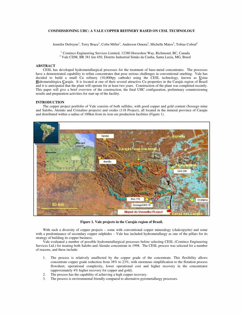
INTRODUCTION The copper project portfolio of Vale consists of both sulfides, with good copper and gold content (Sossego mine
and Salobo, Alemão and Cristalino projects) and oxides (118 Project), all located in the mineral province of Carajás and distributed within a radius of 100km from its iron ore production facilities (Figure 1).
Figure 1. Vale projects in the Carajás region of Brazil.
With such a diversity of copper projects – some with conventional copper mineralogy (chalcopyrite) and some
with a predominance of secondary copper sulphides – Vale has included hydrometallurgy as one of the pillars for its strategy of building its copper business.
Vale evaluated a number of possible hydrometallurgical processes before selecting CESL (Cominco Engineering Services Ltd.) for treating both Salobo and Alemão concentrate in 1998. The CESL process was selected for a number of reasons, and these include:
1. The process is relatively unaffected by the copper grade of the concentrate. This flexibility allows
concentrate copper grade reduction from 38% to 23%, with enormous simplification to the flotation process
flowsheet, operational complexity, lower operational cost and higher recovery in the concentrator
(approximately 4% higher recovery for copper and gold).
2. The process has the capability of achieving a high copper recovery.
3. The process is environmental friendly compared to alternative pyrometallurgy processes.

4. The process is in an advanced stage of development, having treated a number of copper concentrates in a
large-scale demonstration plant as well as in a smaller pilot plant.
5. A process installation would consist mainly of conventional processing equipment and well-known unit
operations.
6. The oxidation of sulphur contained in the concentrate is limited, resulting in low oxygen consumption,
which reduces the production of acid and consequently reduces neutralization costs.
7. Gold can be recovered from the leach residues by conventional methods (roasting and cyanidation) or by the
recently developed CESL hydrometallurgical process.
8. Most hydrometallurgical processes, in particular CESL’s, can deal with high amounts of impurities in an
acceptable way, from operational cost and environmental aspects.
Preliminary studies have indicated comparatively low capital and reasonable operating costs for copper production because of the low sulphur oxidation that is integral to the economics of a hydrometallurgical process.
In the past several years, Vale and Teck Cominco worked very closely to evaluate the application of the CESL copper process to these properties. After several successful pilot and demonstration plant campaigns on Salobo, Alemão and Sossego throughout 1999 to 2004, Vale decided to build a small production scale CESL facility (10,000tpy copper cathode). The UHC plant is located near Canaã dos Carajás where Vale operates its Sossego copper mine. It is anticipated that the plant will operate for at least two years, processing principally Sossego copper concentrate and potentially other Vale prospects.
PLANT DESCRIPTION
Process Overview
The CESL process consists of four main process steps:
1. Copper mineral oxidation. 2. Copper leaching from the oxidation residue. 3. Solvent extraction to produce a high purity electrolyte. 4. Electrowinning to recover copper in commercial product form.
Dry concentrate feed is received at the UHC plant battery limits and is subjected to a light re-grind to increase the surface area of the minerals.
The ground concentrate slurry and recycled acid solution are pumped separately into an agitated, multi-stage pressure oxidation autoclave at 150ºC and 1,380kPag (Figure 2). Oxygen is added into each compartment to achieve oxidation of the copper minerals.
Figure 2. UHC autoclave (2.1 m ID, Grade 12 titanium). Copper is converted from a sulphide mineral to an acid-soluble sulphate salt, which reports to the PO (pressure
oxidation) filter cake. Iron present in the copper mineral is oxidized to hematite, and sulphur is converted to elemental sulphur. Very little sulphur to sulphate oxidation occurs, and therefore acid generation is minimal.
The autoclave final product slurry is discharged continuously through a pressure letdown vessel. Steam is vented from these tanks, reducing the temperature of the slurry to below boiling. Additional cooling of the discharge slurry is required prior to thickening and filtration; this is achieved by recycling the cooled thickener overflow to mix with the hot autoclave discharge slurry. The cooled autoclave discharge slurry is thickened and filtered. Copper is removed from the autoclave leach liquor by solvent extraction before it is recycled through the evaporator and becomes feed to
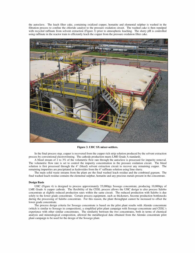
the autoclave. The leach filter cake, containing oxidized copper, hematite and elemental sulphur is washed in the filtration process to confine the chloride catalyst to the pressure oxidation circuit. The washed cake is then repulped with recycled raffinate from solvent extraction (Figure 3) prior to atmospheric leaching. The slurry pH is controlled using raffinate in the reactor train to efficiently leach the copper from the pressure oxidation filter cake.
Figure 3. UHC SX mixer-settlers.
In the final process step, copper is recovered from the copper rich strip solution produced by the solvent extraction
process by conventional electrowinning. The cathode production meets LME Grade A standards. A bleed stream of 2 to 3% of the volumetric flow rate through the autoclave is processed for impurity removal.
The volumetric flow rate is set to control the impurity concentration in the pressure oxidation circuit. The bleed solution is first processed through the 4° (bleed) solvent extraction circuit to recover any remaining copper. The remaining impurities are precipitated as hydroxides from the 4° raffinate solution using lime slurry.
The main solid waste streams from the plant are the final washed leach residue and the combined gypsum. The final washed leach residue contains the elemental sulphur, hematite and any precious metals present in the concentrate.
Design Basis
UHC (Figure 4) is designed to process approximately 35,000tpy Sossego concentrate, producing 10,000tpy of LME Grade A copper cathode. The flexibility of the CESL process allows the UHC design to also process Salobo concentrate at slightly reduced production rates within the same circuit. The reduced production with Salobo is due solely to the lower grade concentrate. Certain process equipment, such as thickeners, become production bottlenecks during the processing of Salobo concentrate. For this reason, the plant throughput cannot be increased to offset the lower grade concentrate.
The process design criteria for Sossego concentrate is based on the pilot plant results with Alemão concentrate (which is similar to Sossego in composition), a simplified pilot plant campaign with Sossego concentrate and CESL’s experience with other similar concentrates. The similarity between the two concentrates, both in terms of chemical analysis and mineralogical composition, allowed the metallurgical data obtained from the Alemão concentrate pilot plant campaign to be used for the design of the Sossego plant.
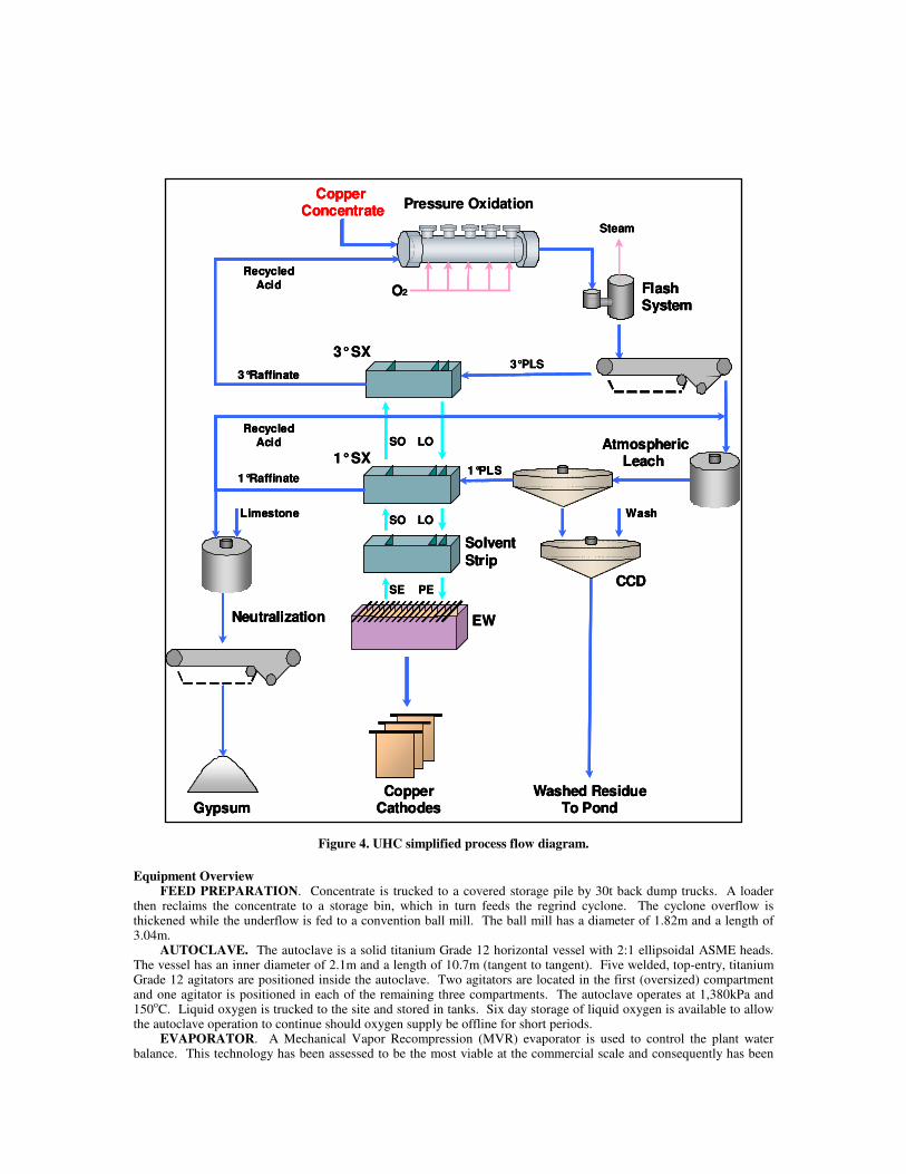
Figure 4. UHC simplified process flow diagram.
Equipment Overview FEED PREPARATION. Concentrate is trucked to a covered storage pile by 30t back dump trucks. A loader
then reclaims the concentrate to a storage bin, which in turn feeds the regrind cyclone. The cyclone overflow is thickened while the underflow is fed to a convention ball mill. The ball mill has a diameter of 1.82m and a length of 3.04m.
AUTOCLAVE. The autoclave is a solid titanium Grade 12 horizontal vessel with 2:1 ellipsoidal ASME heads. The vessel has an inner diameter of 2.1m and a length of 10.7m (tangent to tangent). Five welded, top-entry, titanium Grade 12 agitators are positioned inside the autoclave. Two agitators are located in the first (oversized) compartment and one agitator is positioned in each of the remaining three compartments. The autoclave operates at 1,380kPa and 150oC. Liquid oxygen is trucked to the site and stored in tanks. Six day storage of liquid oxygen is available to allow the autoclave operation to continue should oxygen supply be offline for short periods.
EVAPORATOR. A Mechanical Vapor Recompression (MVR) evaporator is used to control the plant water balance. This technology has been assessed to be the most viable at the commercial scale and consequently has been
Pressure Oxidation
O2
Recycled
Acid
Copper Concentrate
FlashSystem
Steam
1°SX
3°SX
3°Raffinate
AtmosphericLeach
3°PLS
1°PLS
Wash
CCD
Solvent
Strip
SO LO
Washed ResidueTo Pond
EW
CopperCathodes
Limestone
Neutralization
Gypsum
SO LO
SE PE
1°Raffinate
Recycled Acid
Pressure Oxidation
O2
Recycled
Acid
Copper Concentrate
FlashSystem
Steam
1°SX
3°SX
3°Raffinate
AtmosphericLeach
3°PLS
1°PLS
Wash
CCD
Solvent
Strip
SO LO
Washed ResidueTo Pond
EW
CopperCathodes
Limestone
Neutralization
Gypsum
SO LO
SE PE
1°Raffinate
Recycled Acid
O2
Recycled
Acid
Copper Concentrate
FlashSystem
Steam
1°SX
3°SX
3°Raffinate
AtmosphericLeach
3°PLS
1°PLS
Wash
CCD
Solvent
Strip
SO LO
Washed ResidueTo Pond
EW
CopperCathodes
Limestone
Neutralization
Gypsum
SO LO
SE PE
1°Raffinate
Recycled Acid

selected for the semi-industrial plant. The evaporator unit consists of three heat exchangers, one of which will be offline, on a cleaning cycle, at any given time.
BELT FILTERS. Two belt filters were specified for the UHC plant. The pressure oxidation belt filter controls the chloride level in the primary circuit and measures 1.5m in width and 12m in length, for an under vacuum total filter area of 18m2. The neutralization belt filter controls the copper losses from the entrained cake liquor and measures 0.5m in width and 4m in length, for a under vacuum total area of 2m2.
COUNTER CURRENT DECANTATION. Leached residue is washed in a CCD circuit containing five thickeners, each measuring 3.5m in diameter. The residue is stored in a lined pond for gold recovery at a later date.
SOLVENT EXTRACTION. The solvent extraction circuit contains nine mixer settlers of conventional design. The settlers range in size from 85.5m2 for the main SX and strip cells, to 1.2m2 for the impurity bleed circuit. The mixer settlers are constructed of FRP and are protected by both fire water and emergency foam systems.
ELECTROWINNING. The electrowinning circuit contains 40 conventional polymer concrete cells. A dual media filter is used to remove organic entrainment from the electrolyte. Two rectifiers units are installed, each with one power transformer. The system direct current control varies up to 30,528A and the voltage control varies up to 100V. The rectifier rated power is 1,667kW.
Plant Layout As UHC is located in an environmentally sensitive area close to the Carajás National Forest, care and attention has
been taken to ensure environmental protection. The plant is designed with suitable containment areas with all run-off being collected and incorporated back into the plant. The solvent extraction (SX), tank farm and process ponds are equiped with leak detection equipment. This proved invaluable during construction as a check against construction quality.
The vapor discharge from pressure oxidation (PO) are scrubbed before discharge to the atmosphere and all plant effluent is treated for metals removal prior to discharge. Similarly, personnel safety issues have been identified and considered in the design.
The entire plant lies within the footprint of land owned by Vale, adjacent to the Sossego tailings ponds. All of the unit operations within the plant are open. Rain roofs are necessary over the belt filters, mixer settlers, electrowinning, organic and electrolyte storage tanks. See Table 1 and Figure 5 for details.
Table 1. General arrangement legend.
1 Plant Facilities
2 Oxygen Plant
3 Utilities
4 Bleed Treatment, Lime & Limestone
5 Neutralization
6 Reagents Storage
7 Steam Boiler
8 Concentrate Regrind
9 Reagents Preparation
10 Atmospheric Leach (AL) and CCD
11 Pressure Oxidation (PO)
12 Evaporator
13 Cooling Tower
14 Electrical Substation & Control Room
15 Solvent Extraction
16 Tank Farm
17 Crud Treatment
18 Sulphuric Acid Storage
19 Electrowinning (EW)
20 EW Rectifier
21 Warehouse
Construction All industrial civil works are complete and the electrical and mechanical erection was completed at the end of May
2008. Like all projects today, there were many challenges leading to delays. The biggest challenge was a lack of workers as Vale has given priority to contract local workers (about 85% of the contractors were from the region) to develop the area and further build a relationship with the community. This policy and the need for exotic construction materials (for example, titanium) proved difficult, but ultimately successful.
Delivery times from vendors also provided a challenge; this is a relatively small project and gaining vendor attention was difficult for some pieces of equipment. The procurement process took longer than expected and custom delays further contributed to schedule creep.

The UHC project had a total staff count as shown in Figure 6. This includes all project staff from construction and owner’s team.
Figure 5. UHC general arrangement.
Figure 6. Total staff (by month) supporting UHC construction.
0
200
400
600
800
1000
1200
Oct-0
5
Nov-0
5
Dec
-05
Jan
-06
Feb
-06
Mar-0
6
Apr-0
6
May-0
6
Jun
-06
Jul-0
6
Aug
-06
Se
p-0
6
Oct-0
6
Nov
-06
Dec-0
6
Jan
-07
Feb
-07
Mar-0
7
Apr-0
7
May
-07
Jun
-07
Jul-07
Aug
-07
Sep
-07
Oct-0
7
Nov-0
7
Dec
-07
Jan
-08
Feb
-08
Mar-0
8
Apr-0
8
May
-08
To
tal S
taff
DETAILED
ENGINEERING
EARTH WORKS &
CIVIL CONSTRUCTION
ELECTRICAL & MECHANICAL
CONSTRUCTION
PRECOMMISSIONING
& COMMISSIONING

COMMISSIONING A detailed commissioning plan was created to methodically check every piece of equipment, instrument, control
and interlock. The goal was to reduce the impact of potential problems which otherwise may have been encountered during first feed. Like all things in the real world, the plan was adjusted to reflect equipment availability, delays, limitations and deficiencies. The following sections detail some of the more interesting commissioning activities.
Autoclave The commissioning of the autoclave proved to be challenging for a variety of reasons, including:
1. The absence of a pressure source beyond the 125psig supply pressure of the compressed air present (both the oxygen and steam systems were unavailable at the time of commissioning).
2. The need to commission the autoclave at the operating pressure (200psig). 3. The level of complexity surrounding the autoclave installation and the exotic materials of construction
present. 4. The relative inexperience of new plant operators (with very limited exposure to the process equipment
present). 5. The fact that the autoclave area is highly instrumented with two levels of instrumentation present
(operational alarms and controls, and a safety override system), both of which required commissioning.
After successful commissioning of the autoclave with compressed air at the 125psig supply pressure, the slurry feed pumps (Figure 7) were commissioned to provide the operating pressure required to further commission the autoclave. Both the slurry feed pump and the installed spare were successfully commissioned with strong support from the vendor. The slurry feed pump commissioning objectives were all met and included:
1. The review and approval of the pump installations. 2. Testing of the pumps (both at atmospheric pressure and with back pressure in the autoclave). 3. Recording of baseline measurements (including flow, pressure, motor current, vibration and
temperature). 4. Training of the operators. 5. Training of the maintenance staff (including a complete mock pump overhaul).
The commissioned slurry feed pumps were then operated to provide the operating pressure required to complete the autoclave commissioning activities.
The autoclave agitators and the agitator seal water system were commissioned at operating pressure with the support of the agitator vendor. This commissioning activity proved successful; however, during the final commissioning test, the mechanical seal in the third compartment failed. Upon investigation, it was discovered that an operator inadvertently stopped the seal water, causing the mechanical seal to lose its over-pressure, shatter and break. During the commissioning of the agitators, several process parameters were outside of the normal operating boundaries, resulting in the need for several bypassed interlocks and vulnerable PLC seal protection.
This failure provided the maintenance team with an excellent opportunity to replace an agitator mechanical seal. During the seal replacement, valuable knowledge of the procedure and wrench time required was gained. This opportunity also reinforced the need to complete a thorough review of the critical spare parts list required for the entire plant. Due to long procurement times, delays at Brazilian customs and a remote site location, the delivery time for the agitator seal was exceptionally long, reinforcing the need to identify and purchase critical spare parts in order to minimize future down time.
Figure 7. Autoclave slurry feed pumps. Figure 8. Electrolyte filter & back flush tank.
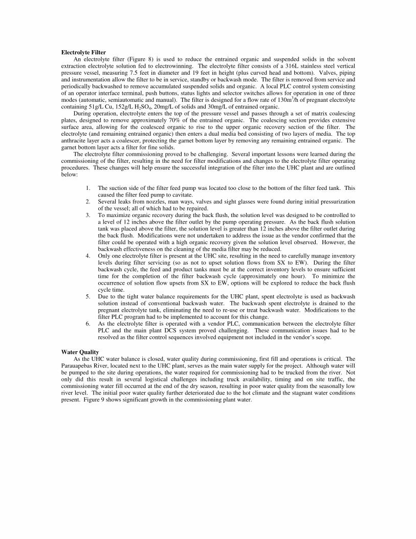
Electrolyte Filter An electrolyte filter (Figure 8) is used to reduce the entrained organic and suspended solids in the solvent
extraction electrolyte solution fed to electrowinning. The electrolyte filter consists of a 316L stainless steel vertical pressure vessel, measuring 7.5 feet in diameter and 19 feet in height (plus curved head and bottom). Valves, piping and instrumentation allow the filter to be in service, standby or backwash mode. The filter is removed from service and periodically backwashed to remove accumulated suspended solids and organic. A local PLC control system consisting of an operator interface terminal, push buttons, status lights and selector switches allows for operation in one of three modes (automatic, semiautomatic and manual). The filter is designed for a flow rate of 130m3/h of pregnant electrolyte containing 51g/L Cu, 152g/L H2SO4, 20mg/L of solids and 30mg/L of entrained organic.
During operation, electrolyte enters the top of the pressure vessel and passes through a set of matrix coalescing plates, designed to remove approximately 70% of the entrained organic. The coalescing section provides extensive surface area, allowing for the coalesced organic to rise to the upper organic recovery section of the filter. The electrolyte (and remaining entrained organic) then enters a dual media bed consisting of two layers of media. The top anthracite layer acts a coalescer, protecting the garnet bottom layer by removing any remaining entrained organic. The garnet bottom layer acts a filter for fine solids.
The electrolyte filter commissioning proved to be challenging. Several important lessons were learned during the commissioning of the filter, resulting in the need for filter modifications and changes to the electrolyte filter operating procedures. These changes will help ensure the successful integration of the filter into the UHC plant and are outlined below:
1. The suction side of the filter feed pump was located too close to the bottom of the filter feed tank. This
caused the filter feed pump to cavitate. 2. Several leaks from nozzles, man ways, valves and sight glasses were found during initial pressurization
of the vessel; all of which had to be repaired. 3. To maximize organic recovery during the back flush, the solution level was designed to be controlled to
a level of 12 inches above the filter outlet by the pump operating pressure. As the back flush solution tank was placed above the filter, the solution level is greater than 12 inches above the filter outlet during the back flush. Modifications were not undertaken to address the issue as the vendor confirmed that the filter could be operated with a high organic recovery given the solution level observed. However, the backwash effectiveness on the cleaning of the media filter may be reduced.
4. Only one electrolyte filter is present at the UHC site, resulting in the need to carefully manage inventory levels during filter servicing (so as not to upset solution flows from SX to EW). During the filter backwash cycle, the feed and product tanks must be at the correct inventory levels to ensure sufficient time for the completion of the filter backwash cycle (approximately one hour). To minimize the occurrence of solution flow upsets from SX to EW, options will be explored to reduce the back flush cycle time.
5. Due to the tight water balance requirements for the UHC plant, spent electrolyte is used as backwash solution instead of conventional backwash water. The backwash spent electrolyte is drained to the pregnant electrolyte tank, eliminating the need to re-use or treat backwash water. Modifications to the filter PLC program had to be implemented to account for this change.
6. As the electrolyte filter is operated with a vendor PLC, communication between the electrolyte filter PLC and the main plant DCS system proved challenging. These communication issues had to be resolved as the filter control sequences involved equipment not included in the vendor’s scope.
Water Quality As the UHC water balance is closed, water quality during commissioning, first fill and operations is critical. The
Parauapebas River, located next to the UHC plant, serves as the main water supply for the project. Although water will be pumped to the site during operations, the water required for commissioning had to be trucked from the river. Not only did this result in several logistical challenges including truck availability, timing and on site traffic, the commissioning water fill occurred at the end of the dry season, resulting in poor water quality from the seasonally low river level. The initial poor water quality further deteriorated due to the hot climate and the stagnant water conditions present. Figure 9 shows significant growth in the commissioning plant water.
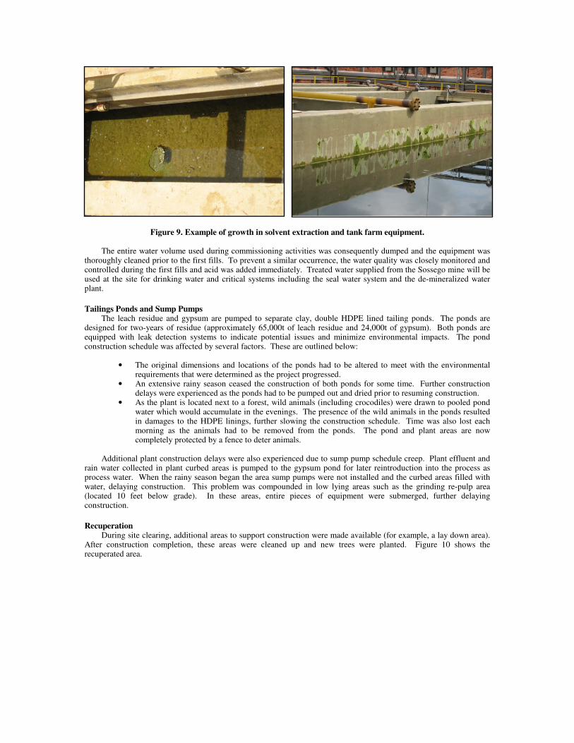
Figure 9. Example of growth in solvent extraction and tank farm equipment. The entire water volume used during commissioning activities was consequently dumped and the equipment was
thoroughly cleaned prior to the first fills. To prevent a similar occurrence, the water quality was closely monitored and controlled during the first fills and acid was added immediately. Treated water supplied from the Sossego mine will be used at the site for drinking water and critical systems including the seal water system and the de-mineralized water plant.
Tailings Ponds and Sump Pumps The leach residue and gypsum are pumped to separate clay, double HDPE lined tailing ponds. The ponds are
designed for two-years of residue (approximately 65,000t of leach residue and 24,000t of gypsum). Both ponds are equipped with leak detection systems to indicate potential issues and minimize environmental impacts. The pond construction schedule was affected by several factors. These are outlined below:
• The original dimensions and locations of the ponds had to be altered to meet with the environmental
requirements that were determined as the project progressed. • An extensive rainy season ceased the construction of both ponds for some time. Further construction
delays were experienced as the ponds had to be pumped out and dried prior to resuming construction. • As the plant is located next to a forest, wild animals (including crocodiles) were drawn to pooled pond
water which would accumulate in the evenings. The presence of the wild animals in the ponds resulted in damages to the HDPE linings, further slowing the construction schedule. Time was also lost each morning as the animals had to be removed from the ponds. The pond and plant areas are now completely protected by a fence to deter animals.
Additional plant construction delays were also experienced due to sump pump schedule creep. Plant effluent and
rain water collected in plant curbed areas is pumped to the gypsum pond for later reintroduction into the process as process water. When the rainy season began the area sump pumps were not installed and the curbed areas filled with water, delaying construction. This problem was compounded in low lying areas such as the grinding re-pulp area (located 10 feet below grade). In these areas, entire pieces of equipment were submerged, further delaying construction.
Recuperation During site clearing, additional areas to support construction were made available (for example, a lay down area).
After construction completion, these areas were cleaned up and new trees were planted. Figure 10 shows the recuperated area.
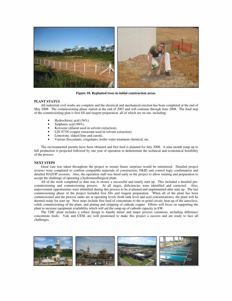
Figure 10. Replanted trees in initial construction areas.
PLANT STATUS All industrial civil works are complete and the electrical and mechanical erection has been completed at the end of
May 2008. The commissioning phase started at the end of 2007 and will continue through June 2008. The final step of the commissioning plan is first fill and reagent preparation, all of which are on site, including:
• Hydrochloric acid (36%). • Sulphuric acid (98%). • Kerosene (diluent used in solvent extraction). • LIX 973N (copper extractant used in solvent extraction). • Limestone, slaked lime and caustic. • Various flocculants, coagulants, boiler water treatment chemical, etc.
The environmental permits have been obtained and first feed is planned for July 2008. A nine month ramp up to full production is projected followed by one year of operation to demonstrate the technical and economical feasibility of the process.
NEXT STEPS Great care was taken throughout the project to ensure future surprises would be minimized. Detailed project
reviews were completed to confirm compatible materials of construction, P&ID and control logic confirmation and detailed HAZOP sessions. Also, the operation staff was hired early in the project to allow training and preparation to accept the challenge of operating a hydrometallurgical plant.
All of the work completed to date was to ensure a successful and timely start up. This included a detailed pre-commissioning and commissioning process. At all stages, deficiencies were identified and corrected. Also, improvement opportunities were identified during this process to be evaluated and implemented after start up. The last commissioning phase of the project included first fills and reagent preparation. When all of the plant has been commissioned and the process tanks are at operating levels (both tank level and acid concentrations), the plant will be deemed ready for start up. Next steps include first feed of concentrate to the re-grind circuit, heat up of the autoclave, solids commissioning of the plant, and plating and stripping of cathode copper. Efforts will focus on supporting the plant to increase equipment availability which will aid the ramp up of cathode capacity in EW.
The UHC plant includes a robust design to handle minor and major process variations, including difference concentrate feeds. Vale and CESL are well positioned to make this project a success and are ready to face all challenges.