COMMISSIONING INSTRUCTIONS INTEGRAL+ CONTROL AND … · The electronic board includes an automatic...
80
COMMISSIONING INSTRUCTIONS MANUEL DE MISE EN SERVICE BEDIENUNGSHANDBUCH INTEGRAL+ CONTROL AND POSIGAM+ COMMANDE INTEGRAL+ ET POSITIONNEUR POSIGAM+ INTEGRAL-PLUS STEUERUNG UND POSIGAM-PLUS INTEGRAL+ NR1088_AFD_rev G Art : 5100052
Transcript of COMMISSIONING INSTRUCTIONS INTEGRAL+ CONTROL AND … · The electronic board includes an automatic...

COMMISSIONING INSTRUCTIONSMANUEL DE MISE EN SERVICE
BEDIENUNGSHANDBUCH
INTEGRAL+ CONTROL ANDPOSIGAM+
COMMANDE INTEGRAL+ ETPOSITIONNEUR POSIGAM+
INTEGRAL-PLUS STEUERUNG UNDPOSIGAM-PLUS
INTEGRAL+NR
1088
_AFD
_rev
GA
rt :
5100
052

2
DRAWINGS Page 3
1 INTRODUCTION Page 42 FAST VALVE SET-UP Page 43 CONFIGURATION Page 44 POWER SUPPLY Page 4 4.1 Actuator power supply Page 4 4.2 Output power supplya Page 55 ACTUATOR OPERATION Page 5 5.1 Direction of rotation Page 5 5.2 Closing type Page 5 5.3 By-pass of open torque switch when starting to open from closed position Page 6 5.4 Rotation reverse relay Page 66 REMOTE CONTROL Page 6 6.1 Dry contacts control Page 7 6.2 Voltage control Page 7 6.3 Single dry contact control Page 7 6.4 Priority to open or to close Page 8 6.5 Emergency control (ESD) Page 8 6.6 Local control inhibition Page 97 LOCAL CONTROL Page 10 7.1 Self-holding local control Page 10 7.2 Local stop Page 10 7.3 General stop Page 10 7.4 Local/remote selector padlock Page 108 INDICATIONS Page 11 8.1 Blinking indications Page 11 8.2 Indication relay N°1 Page 12 8.3 Indication relay N°2 Page 12 8.4 Indication relay N°3 Page 12 8.5 Indication relay N°4 Page 13 8.6 Fault monitoring relay Page 139 FUSES PROTECTION Page 1510 POSITIONER OPTION Page 15 10.1 Input signal configuration Page 15 10.1.1 Operation with signal 0-20mA Page 15 10.1.2 Operation with signal 0-10V Page 15 10.2 Operation direction configuration Page 15 10.3 ‘Stay put’ function configuration Page 16 10.4 Dead band adjustment Page 16 10.5 Local operation Page 16 10.6 Adjustment of 0% Page 17 10.7 Adjustment of 100% Page 17 10.8 Split range Page 17 10.9 Operation with 4-20mA transmitter Page 18 10.10 Remote control AUTO/ON-OFF Page 1811 LOCAL INDICATION OPTION Page 1812 TIMING CONTROL BOARD OPTION Page 1812 TROUBLESHOOTING INTEGRAL+ VERSION Page 2014 TROUBLESHOOTING OF POSITIONER VERSION Page 2315 USER’S SETTING Page 50
CONTENTS

3
GAM-K POSITIONER SETTINGCONFIGURATION POSITIONNEUR GAM-KGAM-K POSITIONER EINSTELLUNG
100% setting potentiometerPotentiomètre réglage 100%Potentiometer für die 100%Einstellung
Local control switchCommutateur commande manuelle
Lokal- Kontroll-Schalter
Actuator running in open direction LEDVoyant manoeuvre d’ouverture
LED für die Laufanzeige inRichtung offen
LED for actuator runningin closing direction
Voyant manoeuvre de fermetureLED für die Laufanzeige in
Richtung schließen
Potentiometer for local controlPotentiomètre de commande localePotentiometer für lokale Steuerung
Dead-band setting potentiometerPotentiomètre de réglage de la bande-mortePotentiometer für dieTotband-Einstellung
Configuration switchesCommutateurs de configurationKonfigurationsschalter
Local control buttonsBoutons de commande locale
Lokale Steuerschalter
Terminal stripBornier de connexion
Klemmenleiste
Electronic board configurationCarte de configuration
Konfiguration der elektronischen Steuerung
FPI HOUSINGBOITIER FPIFPI GEHÄUSEFurnished with screws,nuts & diagramFourni avec vis,rondelles et schémaAusgestattet mitSchrauben, Muttern& Diagramm
Switch off the power supply before removing the terminal strip cover.Couper l’alimentation avant d’enlever le couvercle du bornier de connexion.
Bevor Sie den Klemmenleistendeckel entfernen, schalten Sie die Spannungsversorgung aus.
CI2701 INTEGRAL+ BOARD SETTING
CONFIGURATIONCARTE CI2701INTEGRAL+
INTEGRAL-PLUSPLATINENEINSTELLUNGENConfiguration jumpersCavaliers de configurationJumper Einstellungen
Configuration switchesCommutateurs
de configurationDIL-Schalter- Funktionen
Thermal sensor tripped LEDVoyant alarme
protection thermiqueAnzeige-LED für
“Thermokontakt ausgelöst”
Torque switch tripped LEDVoyant limiteur
d’effort activéAnzeige-LED für
“Drehmoment ausgelöst”
Secondary fusesFusibles secondaires
Zweitsicherungen
Secondary fusesFusibles secondaires
Zweitsicherungen
Actuator closingLED indicatorVoyant fermetureservomoteurAnzeige-LED für “Antrieb schließt”
Actuator openingLED indicatorVoyant ouvertureservomoteurAnzeige-LED für “Antrieb öffnet”

4
1 INTRODUCTION
The configuration panel of the INTEGRAL+ board allows to adapt the actuator at each particular application. Information to be transmitted and actuator behaviour configuration are set with swit-ches and jumpers. The actuator is deliverable with standard configuration, or optional configuration if requested at order. The configuration can be easily changed on site.The jumper and switches settings can be reported in a table on page 39.
2 FAST VALVE SET-UP
If the INTEGRAL+/POSIGAM+ control doesn’t need specific configuration, you can refer directly to the detachable document located in the center of this document for a fast and easy setting of the valve position. This description considers valve closing on position. For POSIGAM+, description considers input/output signals are 4/20mA.
For specific parameters, please follow the descriptions in the following chapters.
3 CONFIGURATION
Configuration is easily done by changing switches and jumpers position.
Basic/standard” configuration (default setting): all switches and jumpers are in position A.
4 POWER SUPPLY
4.1 ACTUATOR POWER SUPPLY
Actuator power supply can be 3 phase, single phase or DC.
Jumper 100 (located at the bottom of the board)The electronic board includes an automatic phase correction device and a detection of missingphase device. In 3 phase supply, whatever the power connection, the actuator always rotatesin the right direction. If, in 3 phase supply, one phase is lost, the actuator stops automaticallyand the monitoring relay drops.
Figure 2Switches configuration
Figure 3Jumpers configuration

5
English
In single phase or DC supply, one must inhibit the automatic phase correction and the detection of missing phase by moving the jumper 100 to position M.
- Single phase or DC power supply
4.2 OUTPUT POWER SUPPLY
One power supply unit 23V - 1,2VA DC is available (through the card CI2701) to power a remote position current transmitter and remote controls dry contacts. This power supply unit is isolated from the other electrical circuits.
5 ACTUATOR OPERATION
5.1 DIRECTION OF ROTATION
In standard, the actuator closes clockwise.
Switch 7Move the switch 7 to position B for the valves closing counter-clockwise. This switch reverses: - The motor direction of rotation - The limit switches - The torque switches
- Closing counter-clockwise
5.2 CLOSING TYPE
In standard, the actuator closes on limit switch.
Switch 1Move switch 1 to position B for closing on torque switch (only for actuator equipped with torque limit switches). The associated limit switch must also be operated when the valve is closed.
- Closing on torque switch
The limit switch is used for valve closed indication and also allows to detect stopping on torque switch at mid-stroke as a fault and stopping on torque switch in closed position as normal.

6
5.3 BY-PASS OF OPEN TORQUE SWITCH WHEN STARTING TO OPEN FROM CLOSED POSITION
In standard, the open torque switch is active on the whole actuator stroke.
Switch 6Move switch 6 to position B to by-pass the open torque switch by the closed limit switch when starting to open from the closed position.
- By-pass the open torque switch by the closed limit switch in closed position
This must be used when actuator including mechanically maintained torque switches [SR type] isset for closing on torque switch. This avoid the open torque switch to trip when starting to open.
5.4 ROTATION REVERSE DELAY
In standard the reverse delay is 50ms. Jumper on support 25 in position 50ms.
Jumper 25Move the jumper on support 25 to position 200ms to have a reverse delay of 200ms.
- Reverse delay of 200 ms
Note: the setting of the reverse delay is a factory setting. It allows the use of bigger single phase motors.
6 REMOTE CONTROL
Remote control of an actuator equipped with the electronic board CI2701 can be done from an exter-nal voltage supply or an internal voltage supply. Inputs on the board are completely isolated by opto-isolators.Pulse commands (with self-holding) requires 4 wires connected to the customer terminal board: Com-mon, stop, open and close. If the stop button is not used, do not connect the wire STOP, open contact (or close) must be maintained to operate the actuator.

7
English
6.1 DRY CONTACTS CONTROL
In case of dry contact control, a jumper must be put on customer terminals 5-6
6.2 VOLTAGE CONTROL
Remote control can be done either in AC or DC voltage.For lower voltages from 10 to 55V, use common terminal 5.For higher voltages from 90 to 250V, use common terminal 4.
6.3 SINGLE DRY CONTACT CONTROL
It is possible to control the actuator with a single external dry contact. - Contact closed: opening of the valve - Contact open: closing of the valveOne must configure the actuator for priority to open (see 5.4).
The opposite control is possible : - Contact closed: closing of the valve - Contact open: opening of the valveOne must configure the actuator for priority to close (see 5.4).
456789
10
456789
10
45678910
456789108
90
45678910
456789
10
Caution : never connect voltage higher than 55V on common terminal 5.

8
6.4 PRIORITY TO OPEN OR TO CLOSE
In standard there is no priority to open or to close. These priorities are used to: - Change the direction during operation without going through a stop command. In that case prio-
rity to Open and to Close are needed. - Give priority to one position: if the actuator receives both open and close command and a priority
to Open or to Close are needed. - Control by a single dry contact
Switches 9 and 10Move switch 9 to position B for priority to Close.Move switch 10 to position B for priority to Open.
- Priority to Close
- Priority to Open
- Change of operationdirection without goingthrough a stop command
Priority command stops the pending operation and is immediately active.
6.5 EMERGENCY COMMAND (ESD)
ESD (Emergency Shut Down) is a remote emergency control, with priority on all other controls. According to the valve operation, ESD can be open command or close command. To increase the availability of the actuator in extreme conditions, ESD can also override the motor thermal sensor.
Note: ESD is not available when local / remote selector is in position «OFF».
In standard, ESD control is performed by closing a contact. Jumper 27 position:

9
English
Jumper 27Move jumper 27 position to have ESD by opening a contact.In standard, ESD control is a close command. Jumper 28 position CLOSE.
Jumper 28Move jumper 28 to position OPEN for open command.In standard, ESD control does not override the motor thermal sensor
Switch 8Move switch 8 to position B to by-pass the motor thermal sensor when ESD control.
- Configuration of ESD control: jumpers 27 and 28
- By-pass of motor thermal sensor when ESD control.
6.6 LOCAL CONTROL INHIBITION
The inhibition of the local control is a remote command. This command freezes open and close commands sent in local and authorise remote commands even if the local / remote selector is in local position.In standard configuration, local stop and general stop remain possible locally on the actuator.
For inhibition of local stop and general stop, see 6.3 (switch 4 on position B).
Caution : In this configuration, if ESD input is not connected, the actuator receives an ESD operation command as soon
as powered on. If no ESD wire is available at the start-up
stage, it is recommended to add a jumper at the wiring
terminal strip (in place of ESD wire) prior to power on.
Note: the command inhibition of local control is not available with the option positioner. It is replaced [automatically] by the function AUTO / ON-OFF CONTROL.
456789101112
456789101112
90

10
7 LOCAL CONTROL
As for remote control, local control can be used. A local selector allows to choose between remote and local control. The button for local control open, close allows to operate the actuator in the appropriate direction. Local stop is done by a momentary rotation of the local / remote selector.
7.1 SELF-HOLDING LOCAL CONTROL
In standard, local controls are self-holding. (One pulse is enough to send a close or open command)
Switch 5
Move switch 5 to position B to cancel the self-holding. (Open or close com-mand must be maintained during the operation)
- Local control without self-holding
7.2 LOCAL STOP
In standard, it is possible to stop the actuator locally, even if the selector local / remote is on remote position.
7.3 GENERAL STOP
In standard, it is possible to do a general stop of the actuator. Move the selector local / remote to position OFF. No electrical controls in local or remote is therefore possible. If the remote command local control inhibition is used, priority remains to the function general stop.
Switch 4
Move switch 4 to position B to prohi-bit local stop and OFF position when local control inhibition.
- Local stop impossible if local control inhibition.
7.4 LOCAL / REMOTE SELECTOR PADLOCK
The local / remote selector can be padlocked in position OFF, local or remote.

11
English
8 INDICATIONS
Remote indication is done through 5 relays: - Four relays ‘single contact’ for operation indications. Contacts can be normally open
wor normally closed.Note : Voltage free, relays are always with normally open contact. - One reversing relay for fault monitoring.Note : The monitoring relay is normally energised and drops in case of fault.
Relays information (Grey : standard configuration):
8.1 BLINKING INDICATIONS
In standard, information: - Actuator running electrically - Actuator opening electrically - Actuator closing electricallyare not blinking.
Switch 11
Move switch 11 to position B to have the 3 informations blinking.
Indications- Actuator running- Actuator opening- Actuator closing are blinking
N° Relay Information to be transmitted Location of jumper Customer terminal
Relay 1Limit switch openTorque switch open
14 - LSO14 - TSO
13 - 14
Relay 2Limit switch closeTorque switch close
15 - LSC15 - TSC
15 - 16
Relay 3
Limit switch openTorque switch openLocal/remote selector on localLocal/remote selector on remoteActuator moving electricallyActuator opening electrically
16 - LSO16 - TSO17 - LOCAL17 - REMOTE18 - RUNNING18 - OPENING
17 - 18
Relay 4
Limit switch closeTorque switch closeActuator receives an emergency command (ESD)Actuator closing electricallyLocal/remote selector on localLocal/remote selector on remote
19 - LSC19 - TSC20 - ESD20 - CLOSING21 - LOCAL21 - REMOTE
19 - 20

12
8.2 INDICATION RELAY N°1
In standard, relay N°1 indicates limit switch open. Jumper 14 in position LSO (Limit Switch Open).
Jumper 14Move jumper 14 to position TSO (Torque Switch Open) for relay N°1 to indicate torque switch open.In standard, relay N°1 is with contact normally open. Jumper 22 in position
Jumper 22
Move jumper 22 to position for relay N°1 to be with contact normally close.
- Configuration relay 1: jumpers 14 and 22
8.3 INDICATION RELAY N°2
In standard, relay N°2 indicates limit switch close. Jumper 15 in position LSC (Limit Switch Close).
Jumper 15Move jumper 15 to position TSC (Torque Switch Close) for relay N°2 to indicate torque switch close.In standard, relay N°2 is with contact normally open. Jumper 23 in position
Jumper 23
Move jumper 23 to position for relay N°2 to be with contact normally closed.
- Configuration relay 2: Jumpers 15 and 23
8.4 INDICATION RELAY N°3
In standard, relay N°3 indicates limit switch open. Jumper 16 in position LSO (Limit Switch Open).
Jumper 16, 17 and 18
NOTE: There is only one jumper for the three jumper holders number 16, 17 and 18
- Move jumper to holder 16 / TSO (Torque Switch Open) for relay N°3 to indicate torque switch open.
- Move jumper to holder 17 / REMOTE for relay N°3 to indicate local/remote selector in position remote.
- Move jumper to holder 17 / LOCAL for relay N°3 to indicate local/remote selector in position local.
- Move jumper to holder 18 / OPENING for relay N°3 to indicate an actuator opening movement. - Move jumper to holder 18 / RUNNING for relay N°3 to indicate that actuator is running.
In standard, relay N°3 is with contact normally open. Jumper 24 in position

13
English
Jumper 24
Move jumper 24 to position for relay N°3 to be with contact normally closed.
- Configuration relay 3: jumper 16, 17, 18 and 24.- Only one jumper on holders 16,17 and 18.
8.5 INDICATION RELAY N°4
In standard, relay N°4 indicates limit switch closed. Jumper 19 in position LSC (Limit Switch Close).
Jumper 19, 20 and 21
NOTE: There is only one jumper for the three jumper holders number 19, 20 and 21
- Move jumper to holder 19 / TSC (Torque Switch Close) for relay N°4 to indicate torque switch close.
- Move jumper to holder 20 / CLOSING for relay N°4 to indicate that actuator is closing the valve.
- Move jumper to holder 20 / ESD (Emergency Shut Down) for relay N°4 to indicate that actuator is receiving an ESD command.
- Move jumper to holder 21 / REMOTE for relay N°4 to indicate local/remote selector in position remote.
- Move jumper to holder 21 / LOCAL for relay N°4 to indicate local/remote selector in position local.
In standard, relay N°4 is with contact normally open. Jumper 26 is in position
Jumper 26
Move jumper 26 to position for relay N°4 to be with contact normally closed.
- Configuration relay 4: jumpers 19, 20, 21 and 26- Only one jumper on 19, 20 and 21
8.6 FAULT MONITORING RELAY
The fault monitoring relay indicates a non-availability of the actuator or an abnormal operation.The fault monitoring relay is normally energised, and is disenergised in case of fault.The relay is disenergised upon the following events: - Loss of main power supply, control voltage, fuse - Loss of 1 phase (in case of 3 phase supply) - Tripping of motor thermal protection - Loss of input signal 4-20mA (with option positioner)* - Local/remote selector in position local or off**
* On version without positioner, switch N°2 has no effect.** In case of local controls inhibition, selector in position local is not indicated as a fault, because actuator is still available for the remote commands.).
The user can modify the conditions upon which the relay is disenergised.

14
Switch 2
Move switch 2 to position B for loss of input signal 4-20mA not indicated as a fault. (Positioner only).
- Loss of input signal 4-20mA is not a fault. (Only option positioner)
Switch 3
Move switch 3 to position B for local/remote selector in local or off not indicated as a fault.
- Local/remote selector in local or off is not a fault.
Switch 12
Move switch 12 to position B for trip-ping of torque switch open to be a fault.- Tripping of torque switch close is a
fault.
Switch 13
Move switch 13 to position B for tripping of torque switch close to be a fault.- Tripping of torque switch open is
a fault.
Note : Supervisor system is able to detect if the valve close on torque, and in this case there is no fault indication.

15
English
9 FUSES PROTECTION
Accessibility : - Switch off power supply on actuator. - Remove cover with local control buttons. - Take care of the buttons cable inside the cover. - Unfasten the fuse support covers and change the fuses if necessary.
Fuses data :FU1 : transformer primary fuse 6,3 x 32mm - 0,5A - 500VFU2 : transformer secondary fuse 5 x 20mm - 0,5AFU3 : transformer secondary fuse 5 x 20mm - 0,05A
10 POSITIONER OPTION
The optional positioner board can be connected onto the CI2701 board. The positioner allows the actuator to reach a position proportionally to a command input signal. The configuration panel allows: - To give local positioning commands - To adapt the actuator to the type of input signal - To configure the reaction of the actuator in case of loss of input signal
10.1 INPUT SIGNAL CONFIGURATION
The standard input signal is 4-20 mA.
10.1.1 Operation with signal 0-20 mA
Switches 4 and 8Move switches 4 and 8 to position B for operation with signal 0-20mA. The output signal [position indication] is also 0-20 mA.
10.1.2 Operation with signal 0-10 V
Switches 4, 8, 9 and 10Move switches 4, 8, 9 and 10 to position B for 0-10V input signal. The output signal is 0-20 mA.
10.2 OPERATION DIRECTION CONFIGURATION
The standard is 4 mA valve closed and 20 mA valve open.
Switch 3
Potentiometer connectionMove switch 3 to position B, and move actuator potentiometer connection from position POT STD to position POT REV to obtain 4 mA valve open, and 20 mA valve closed.

16
10.3 ‘STAY PUT’ FUNCTION CONFIGURATION
With input signal 4-20 mA, it is possible to configure a failsafe position in case of loss of input signal.In standard, the function is active, and the actuator stays in position in case of loss of input signal.
Switches 5, 6 and 8Move switch 5 to position B for actuator to open in case of loss of input signal.Move switch 6 to position B for actuator to close in case of loss of input signal.Move switch 8 to position B to disactivate the ‘stay put’ function.
10.4 DEAD BAND ADJUSTMENT
This adjustment is factory done, but one can adjust it with the potentiometer DEAD BAND.To reduce the dead band turn it counter-clockwise.
10.5 LOCAL OPERATION
One can simulate an input signal 4-20 mA locally to check the operation of the actuator. The local/off/remote selector must be on the remote position.
- AUT: Operation by external signal- 0%: Internal signal 0% (4mA in standard)- MAN: Internal signal adjustable from 0 to 100%-100 %: Internal signal 100% (20mA in standard)
Move local control switch to position 0%, MAN or 100%. Turn potentiometer MAN to simulate an input signal 4-20 mA.
Operation direction configuration
Type of inputsignal
Open 4mA 20mA 0mA 20mA 0v 10V
Close 4mA 20mA 0mA 20mA 0v 10V
Valve actionClosing
clockwiseClosing
counterclockwiseClosing
clockwiseClosing
counterclockwise
Configuration Standard
CI2701 board:switch 7 on B
Reverse potentiometer
GAMK board:switch 3 on B
Reverse potentiometer
CI2701 board:switch 7 on BGAMK board:switch 3 on B
Caution: in case of input signal 0-20 mA or 0-10 V, the ‘stay put’ function cannot be used and must be disactivated. Move switch 8 to position B.
Caution: reducing the dead band too much will provoke hunting on the actuator.
17
English
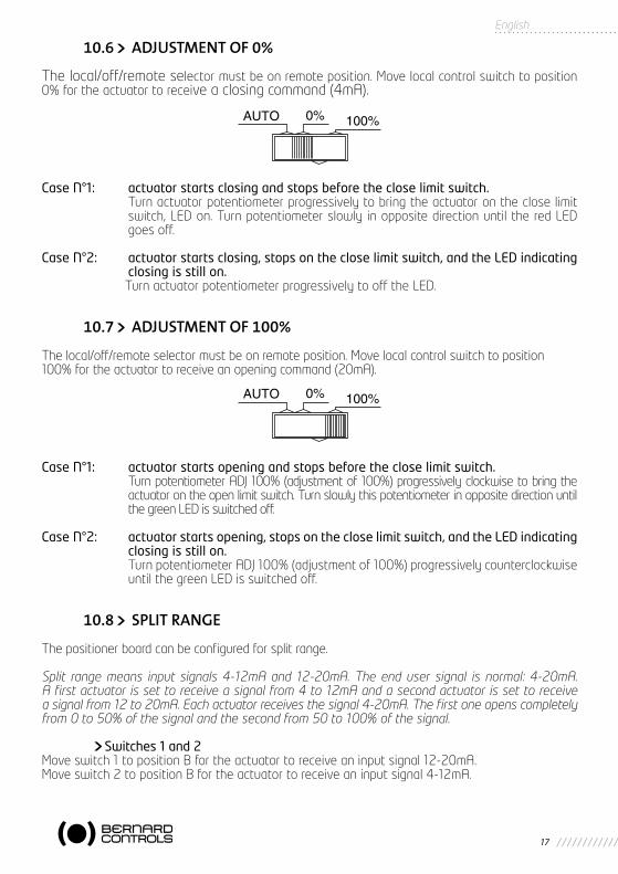
10.6 ADJUSTMENT OF 0%
The local/off/remote selector must be on remote position. Move local control switch to position 0% for the actuator to receive a closing command (4mA).
Case N°1: actuator starts closing and stops before the close limit switch. Turn actuator potentiometer progressively to bring the actuator on the close limit
switch, LED on. Turn potentiometer slowly in opposite direction until the red LED goes off.
Case N°2: actuator starts closing, stops on the close limit switch, and the LED indicating closing is still on.
Turn actuator potentiometer progressively to off the LED.
10.7 ADJUSTMENT OF 100%
The local/off/remote selector must be on remote position. Move local control switch to position100% for the actuator to receive an opening command (20mA).
Case N°1: actuator starts opening and stops before the close limit switch. Turn potentiometer ADJ 100% (adjustment of 100%) progressively clockwise to bring the
actuator on the open limit switch. Turn slowly this potentiometer in opposite direction until the green LED is switched off.
Case N°2: actuator starts opening, stops on the close limit switch, and the LED indicating closing is still on.
Turn potentiometer ADJ 100% (adjustment of 100%) progressively counterclockwise until the green LED is switched off.
10.8 SPLIT RANGE
The positioner board can be configured for split range.
Split range means input signals 4-12mA and 12-20mA. The end user signal is normal: 4-20mA. A first actuator is set to receive a signal from 4 to 12mA and a second actuator is set to receive a signal from 12 to 20mA. Each actuator receives the signal 4-20mA. The first one opens completely from 0 to 50% of the signal and the second from 50 to 100% of the signal.
Switches 1 and 2Move switch 1 to position B for the actuator to receive an input signal 12-20mA.Move switch 2 to position B for the actuator to receive an input signal 4-12mA.

18
10.9 OPERATION WITH A 4-20MA TRANSMITTER
In standard the actuator potentiometer is used to know the valve position.
Switch 7Move switch 7 to position B for operation with a transmitter 4-20mA instead of the actuator potentiometer. The CI2701 board can provide the power supply to the transmitter TAM or FSG.
10.10 REMOTE CONTROL AUTO / ON-OFF CONTROL
With a positioner, one can do remote control by a signal 4-20mA or by open/close/stop commands.The input AUTO / ON-OFF CONTROL on the customer terminal board allows to switch from one type of control to the other one.See chapter 5: remote control for the configuration of the open and close commands.
Note: the remote controls «AUTO / ON-OFF CONTROL» and «LOCAL CONTROL INHIBITION» use the same input on the customer terminal board. The implementation of the positioner automatically allocates this input to the function AUTO / ON-OFF CONTROL. The function «LOCAL CONTROL INHIBI-TION» cannot be used with a positioner.
11 POSITIONER OPTION
In option a local indication through a window at the local controls level shows the actuator status. - Valve open lamp - Valve closed lamp - Actuator power-on lamp
12 TIMING CONTROL BOARD OPTION
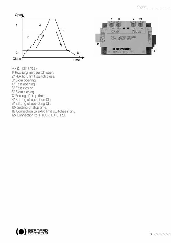
An additional timer control module permits to slow down the speed of the actuator, for example to protect the pipe against hammer blows if stroke time is too fast.This module is connected to entry P202TEMPO of the actuators Integral+ control board. When electric commands are given, the timing action is assured by a STOP and ON function of the motor starter.
The time of operation ON and the time of STOP are adjustable: T. ON : 0,5 sec. to 10 secs. T. STOP : 3 secs. to 2 min.Thus the total time of operation for the valve stroke can be very slow with the advantage of adjust-ment availability at site.
The adjustments for open and closed direction are independent.
By using an auxiliary limit switch it is possible to bypass the timing control as long as the limit switch is activated. This device permits the actuator to operate at rated speed a part of the valve stroke. The length of the limit switch operating cam represents approximately 10% of the total valve stroke.
19
English
FONCTION CYCLE1/ Auxiliary limit switch open.2/ Auxiliary limit switch close.3/ Slow opening.4/ Fast opening.5/ Fast closing.6/ Slow closing.7/ Setting of stop time.8/ Setting of operation ON.9/ Setting of operating ON.10/ Setting of stop time.11/ Connection to extra limit switches if any.12/ Connection to INTEGRAL+ CARD.
Open
Close Time
1 4 5
3
2 6

20
PROBLEM CAUSE CORRECTIVE ACTION
No operation Actuator power supply Check the power supply voltage (terminals 1, 2, 3 in 3 PH voltage or 0, 1 in single phase). The voltage is specified on the identification plate.
A local control inhibit command is present.
Check that the actuator receives no local control inhibit command.With the unit off , the local control inhibit wire, connected to terminal 11 may be removed to carry out a functional check of the actuator.
An emergency control command is present and inhibits all other commands.
Check that the actuator receives no emergency command.With the unit off , jumper #27 may be removed from the INTEGRAL+ board, taking care to record its position to make sure it is replaced at the correct location. With the jumper removed, the ESD function is inhibited, and a functional check of the actuator can be carried out. Return the jumper to original location.
Fuse blown Check fuses and replace as required.
Power supply type configuration
Check position of jumper 100 on the CI2701 board.Three-phase: position TSingle-phase or DC: position M
Tripping of motor thermal protective device
The TH light on the CI2701 board configuration panel indicates thermal tripping of thermal protective device. The actuator will again be available after the motor has cooled off.
The declutchable manual control handwheel remained engaged (only on versions with electrical safety contact)
Check that the handwheel is in disengagedposition.
Configuration jumpers are incorrectly set or missing
There must be 11 jumpers on the CI2701 board.There shall be only one jumper on jumper 16-17-18 support and only one jumper on jumper 19-20-21 support.
13 TROUBLESHOOTING ON INTEGRAL+ VERSION
In case of doubt as to the unit’s functionality, firstly set the local/remote selector switch to local and actuate the local open/close controls.

21
English
PROBLEM CAUSE CORRECTIVE ACTION
The actuator operates in local mode, not in remote mode
Local/remote selector switch set to local or to off
Set the local/remote selector switch to remote.
Contact control: no voltage across terminals 6 and 7.
Check that a shunt is present at the client terminal strip between terminals 5 and 6. Check fuse FU3 on the INTEGRAL+ board.
Voltage control: inappropriate input voltage.
Check connection in voltage control mode: Voltage 10 to 55 V: Terminal strip 5Voltage 90 to 250 V: Terminal strip 4
The actuator operates in remote mode, not in local mode
Local/remote selector switch set to remote or to off
Set the local/remote selector switch to local.
A local control inhibit command is present.
Check that the actuator receives no local control inhibit command.With the unit off , the local control inhibit wire, connected to terminal 11 may be removed to carry out a functional check of the actuator.
The actuator does not rotate in the correct rotational direction
Incorrect configuration Check the rotational direction configuration.Switch 7 of the CI2701 board:Position A: clockwise closingPosition B: counterclockwise closing
Motor has been rewired (motor replacement i.e)
When replacing a motor, wire markings must be observed. In case of doubt, check rotational direction. To reverse the motor rotational direction, change over wires 1 and 2 of the motor terminal strip in the travel switches compartment.
The actuator does not stop on the closing limit switch
The actuator is configured for torque closing.
Check closing configuration (switch 1 of the INTEGRAL+ board).
The closing limit switch is misadjusted.
Adjust the closing limit switch. The closing limit switch must be actuated with the valve closed (even if the actuator is set for torque closing).
Motor has been rewired (motor replacement i.e) and rotates in the reverse direction
When replacing a motor, wire markings must be observed. In case of doubt, check rotational direction. To reverse the motor rotational direction, change over wires 1 and 2 of the motor terminal strip in the travel switches compartment.
The actuator does not stop on the opening limit switch
The opening limit switch is misadjusted.
Adjust the opening limit switch. The opening limit switch must be actuated with the valve open.

22
PROBLEM CAUSE CORRECTIVE ACTION
The actuator does not stop on the ope-ning limit switch
Motor has been rewired (motor replacement i.e) and rotates in the reverse direction
When replacing a motor, wire markings must be observed. In case of doubt, check rotational direction. To reverse the motor rotational direction, change over wires 1 and 2 of the motor terminal strip in the travel switches compartment.
No actuator signalling
The actuator is off Indications are only available with the actuator on .
Torque switch not operating correctly
Incorrect configuration Check that the concerned indication relay has been configured for torque limiter indication.The jumper of the INTEGRAL+ board is set to:TS0 for opening torque limiterTSC for closing torque limiter
The torque limiter has been actuated manually.
The electronics only store the limiter data if a manoeuvre is in progress. The electronics further only stores the data for the torque limiter corresponding to the rotational direction.
Torque switch indication does not return to initial condition once the torque limiter is no longer actuated.
Torque limiter data storage
The torque limiter data are stored electronically.To clear a torque limiter memory, a reverse order must be sent.

23
English
PROBLEM CAUSE CORRECTIVE ACTION
No operation Actuator power supply Check the power supply voltage (terminals 1, 2, 3 in three-phase voltage or 0,1 in single phase). The voltage is specified on the identification plate.
An emergency control command is present and inhibits all other com-mands.
Check that the actuator receives no emergency control command.With the unit off , jumper 27 may be removed from the CI2701 board, taking care to record its position to make sure it is replaced at the correct location. With the jumper removed, the ESD function is inhibited, and a functional check of the actuator can be carried out. Return the jumper to original location.
Fuse blown Check fuses of CI2701 board
Power supply type configuration
Check position of jumper 100 on the C2701 board.Three-phase: position TSingle-phase or DC: position M
Tripping of motor thermal protective device
The TH light on the CI2701 board configuration panel indicates thermal tripping of thermal protective device. The actuator will again be available after the motor has cooled off.
The declutchable manual control handwheel remained engaged (only on versions with electrical safety contact)
Check that the handwheel is in disengaged position.
Configuration jumpers are incorrectly set or missing
There must be 11 jumpers on the CI2701 board.There shall be only one jumper on supports 16-17-18 and only one jumper on supports 19-20-21
The actuator operates in local open/close control mode, not in positioner mode
Local/remote selector switch set to local or to off
Set the local/remote selector switch to remote to use the positioner (even when the positioner is set to manual).
An auto/on-off control order is present and inhibits the positioner
Check that the actuator receives no Auto/on-off control command.Disconnect this remote control (terminal 11) as required for confirmation.
14 TROUBLESHOOTING ON POSITIONER VERSION
In case of doubt as to the unit’s functionality, firstly set the local/remote selector switch to local and actuate the local open/close controls.

24
PROBLEM CAUSE CORRECTIVE ACTION
The actuator operates in local open/close control mode, not in positioner mode
Bad connection between GAM-K (positioner) and CI2701 boards
Check the positioner board-Integral board connection.
The actuator repeater potentiometer is incorrectly set
Turn the actuator potentiometer by a 1/4 turn and adjust as described in commissioning instructions.
Input signal incorrect Check input signal configuration on the positioner board:4-20 mA signal:Switches 4, 9 and 10 set to A0-20 mA signal:Switches 4 and 8 set to BSwitches 9 and 10 set to A0-10 V signal:Switches 4, 8, 9 and 10 set to B
The actuator operates in positioner mode in local mode, not in remote mode
The auto - 0% - 100%switch is not set to Auto
Check setting of Auto - 0% - 100% switchon the positioner board.
Defective signal Check the reference signal using a milliampe-remeter connected in series (terminal 30).
Signal polarity Check that the plus (+) of the signal is present at terminal 30
The actuator does not follow the input signal
Potentiometer reversemounted
Check the potentiometer connection.The potentiometer should be connected to POT STD for:• 4 mA (or (0 mA or 0 V according to signal) =closed position and clockwise direction closing.• 4 mA (or (0 mA or 0 V according to signal) = open position and counterclockwise directionclosingThe potentiometer should be connected to POT REV for:• 4 mA (or (0 mA or 0 V according to signal) = closed position and counterclockwise direction closing.• 4 mA (or (0 mA or 0 V according to signal) = open position and clockwise direction closingCheck signal configuration
Signal reversed or configu-ration incorrect
Switch 3 on positioner board:Position A: 4 mA = valve closedPosition B: 4 mA = valve openCheck rotation direction configuration.
Rotational direction reversed
Switch 3 on CI2701 board:Position A: clockwise direction closingPosition B: counterclockwise direction opening
The actuator repeater potentiometer is incorrectly set
Turn the actuator potentiometer by a quarterturn and repeat adjustments in accordance with commissioning instructions.

25
English
PROBLEM CAUSE CORRECTIVE ACTION
The actuator does not follow the input signal
Motor has been rewired (motor replacement i.e) and rotates in the reverse direction
When replacing a motor, wire markings must be observed. In case of doubt, check rotational direction. To reverse the motor rotational direction, change over wires 1 and 2 of the motor terminal strip in the travel switches compartment.
The actuator does not stop on the closing limit switch
The actuator is configured for torque closing.
Check closing configuration (switch 1 of the CI2701 board).
The closing limit switch is misadjusted.
Adjust the closing limit switch. The closing limit switch must be actuated with the valve closed (even if the actuator is set for torque closing).
The actuator does not stop on the closing limit switch
Position 0% is misadjusted Adjust actuator potentiometer
Motor has been rewired (motor replacement i.e) and rotates in the reverse direction
When replacing a motor, wire markings must be observed. In case of doubt, check rotational direction. To reverse the motor rotational direction, change over wires 1 and 2 of the motor terminal strip in the travel switches compartment.
The actuator does not stop on the opening limit switch
The opening limit switch is misadjusted.
Adjust the opening limit switch. The opening limit switch must be actuated with the valve open.
Position 100% is misadjusted
Adjust 100% potentiometer on positioner board.
Motor has been rewired (motor replacement i.e) and rotates in the reverse direction
When replacing a motor, wire markings must be observed. In case of doubt, check rotational direction. To reverse the motor rotational direction, change over wires 1 and 2 of the motor terminal strip.
No actuator signalling
The actuator is off Indications are only available with the actuator on.
The torque limiter indications are inoperative
Incorrect configuration Check that the concerned indication relay has been configured for torque limiter indication.The jumper of the CI2701 board is set to:TS0 for opening torque limiterTSC for closing torque limiter
The load limiter has been actuated manually.
The electronics only store the limiter data if a manoeuvre is in progress. The electronics further only stores the data for the load limiter corresponding to the rotational direction.

26
PROBLEM CAUSE CORRECTIVE ACTION
Torque limiter indication does not return to initial reading once the torque limiter is no longer actuated.
Torque limiter data storage
The torque limiter data are stored electronically.To clear a torque limiter memory, a reverse order must be sent.
A fault is indicated but the actuator is fully functional.
The input control signal is not present. In standard configuration, the actuator indicates a fault and remains in position.
Send a control signal on the input
The selector switch is set to local or off position. In standard configuration the actuator indicates a fault.
Set the selector switch to remote .

27
Français
SCHEMAS Page 3
1 INTRODUCTION Page 282 REGLAGE RAPIDE Page 283 CONFIGURATION Page 284 ALIMENTATION Page 28 4.1 Alimentation servomoteur Page 28 4.2 Alimentation externe Page 295 FONCTIONNEMENT DU SERVOMOTEUR Page 29 5.1 Sens de rotation Page 29 5.2 Type de fermeture Page 29 5.3 Shunt du limiteur d’effort en début d’ouverture Page 30 5.4 Temps d’inversion Page 306 COMMANDE A DISTANCE Page 30 6.1 Commande par contacts Page 31 6.2 Commande par tension Page 31 6.3 Commande par un contact unique Page 31 6.4 Priorité ouverture ou fermeture Page 32 6.5 Commande d’urgence (ESD) Page 32 6.6 Interdiction de commande locale Page 337 COMMANDE LOCALE Page 34 7.1 Commande locale maintenue Page 34 7.2 Stop local Page 34 7.3 Arrêt général Page 34 7.4 Cadenassage sélecteur local/distance Page 348 SIGNALISATIONS Page 35 8.1 Signalisations clignotantes Page 35 8.2 Relais de signalisation N°1 Page 36 8.3 Relais de signalisation N°2 Page 36 8.4 Relais de signalisation N°3 Page 36 8.5 Relais de signalisation N°4 Page 37 8.6 Relais défaut Page 379 PROTECTION FUSIBLES Page 3910 OPTION POSITIONNEUR Page 39 10.1 Configuration du signal d’entrée Page 39 10.1.1 Utilisation d’un signal 0-20mA Page 39 10.1.2 Utilisation d’un signal 0-10V Page 39 10.2 Configuration du sens de manoeuvre Page 39 10.3 Configuration de la fonction seuil Page 40 10.4 Réglage de la bande morte Page 40 10.5 Manoeuvre locale Page 40 10.6 Réglage du 0% Page 41 10.7 Réglage du 100% Page 41 10.8 Les commandes fractionnées Page 41 10.9 Utilisation d’un transmetteur 4-20MA Page 42 10.10 Commandes à distance AUTO / ON-OFF Page 4211 OPTION SIGNALISATION LOCALE Page 4212 OPTION CARTE DE TEMPORISATION Page 4213 RESOLUTION PROBLEMES VERSION INTEGRAL+ Page 4414 RESOLUTION PROBLEMES POSITIONNEUR Page 4615 CONFIGURATION UTILISATEUR Page 50
SOMMAIRE

28
1 INTRODUCTION
Le panneau de configuration de la commande INTEGRAL+ permet d’adapter le servomoteur aux besoins particuliers de chaques application. La configuration du comportement du servomoteur et des informations transmises se fait à l’aide de commutateurs et de cavaliers. Le servomoteur est livré soit en configuration standard, soit avec une configuration particulière si celle ci est indiquée à la commande. (La configuration peut être modifiée sur site).Les positions des commutateurs et cavaliers peuvent être reportées dans la table en page 37.
2 > REGLAGE RAPIDE
Si le contrôle INTEGRAL+/POSIGAM+ ne nécessite aucune configuration spécifique, vous pouvez vous référer directement au document détachable situé au centre de ce document pour un réglage sur vanne simple et rapide.Cette description considère que le réglage initial est une fermeture sur contrôle de position. Pour la version POSIGAM+, la description considère un signal de position (commande et recopie)de 4/20mA.
Pour les paramétrage spéciaux, merci de vous référer aux autres chapitres.
3 CONFIGURATION
La configuration se fait simplement en déplaçant des commutateurs et des cavaliers.
En configuration “standard”, la plus courante, tous les commutateurs et cavaliers sont sur la position A.
4 ALIMENTATION
4.1 ALIMENTATION SERVOMOTEUR
L’alimentation du servomoteur peut être triphasée, monophasée ou courant continu.
Cavalier 100 (situé sur la carte inférieure)En triphasé, un contrôleur de phase corrige automatiquement le sens des phases. De plus si une phase de l’alimentation manque, le servomoteur ne pourra pas démarrer. Le cavalier 100 doit être sur la position T.
Figure 2Configuration des commutateurs
Figure 3Configuration des cavaliers

29
Français
En monophasé ou en courant continu, il est nécessaire d’inhiber la correction de phase en positionnant le cavalier 100 sur la position M.
- Alimentation monophasée ou Courant Continu
4.2 ALIMENTATION EXTERNE
Une alimentation courant continu 23V-1,2VA est disponible pour alimenter un transmetteur de courant ou une commande à distance par contacts. Cette alimentation est isolée galvaniquement des autres circuits électriques.
5 FONCTIONNEMENT DU SERVOMOTEUR
5.1 SENS DE ROTATION
En standard, le servomoteur ferme en sens horaire.
Commutateur 7Basculer le commutateur 7 sur la position B pour les vannes à fermeture sens anti-horaire. Ce com-mutateur inverse - Le sens de rotation du moteur - Les fins de course - Les limiteurs d’efforts
- Fermeture sens anti-horaire
5.2 TYPE DE FERMETURE
En standard, le servomoteur se ferme sur fin de course.
Commutateur 1Basculer le commutateur 1 sur la position B pour fermer sur limiteur d’effort (uniquement pour un servomoteur équipé de limiteur d’effort). Le fin de course doit être actionné vanne fermée.
- Fermeture sur limiteur d’effort
Le fin de course est utilisé pour la si-gnalisation vanne fermée, et, d’autre part, permet de distinguer un arrêt sur limiteur d’effort en cours de manoeuvre comme un défaut et un arrêt sur limiteur d’effort en position fermée comme normal.

30
5.3 SHUNT DU LIMITEUR D’EFFORT EN DÉBUT D’OUVERTURE
En standard, le limiteur d’effort ouverture est actif sur toute la course du servomoteur.
Commutateur 6Basculer le commutateur 6 sur la position B pour shunter le limiteur d’effort en début d’ouverture par le fin de course fermeture
- Shunter le limiteur d’effort en dé-but d’ouverture par le fin de course fermeture
A utiliser lorsque le servomoteur à limiteur d’effort maintenu mécaniquement (type SR) est réglé en fermeture sur limiteur d’effort. Permet d’éviter un déclenchement du limiteur d’effort au moment de la réouverture.
5.4 TEMPS D’INVERSION
En standard le temps d’inversion est de 50ms. Cavalier 25 en position 50ms.
Cavalier 25Déplacer le cavalier 25 en position 200ms pour avoir un temps d’inversion de 200ms.
- Reverse delay of 200 msTemps d’inversion de 200 ms
Note : le réglage du temps d’inversion est une configuration usine. Il permet de pouvoir utiliser de gros moteurs monophasés.
6 COMMANDE A DISTANCE
La commande à distance d’un servomoteur équipé de la version INTEGRAL+ peut être faite à partir d’une alimentation externe, ou d’une alimentation intégrée.L’entrée de la carte est totalement isolée par des optocoupleurs.La commande impulsionnelle (avec automaintien) nécessite 4 fils de liaison sur le bornier client: Commun, stop, ouverture et fermeture. Si le bouton poussoir arrêt n’est pas utilisé, ne pas raccorder la liaison STOP, le contact ouverture (ou fermeture) doit être maintenu pour actionner le servomoteur.
31
Français
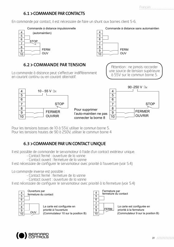
6.1 COMMANDE PAR CONTACTS
En commande par contact, il est nécessaire de faire un shunt aux bornes client 5-6.
6.2 COMMANDE PAR TENSION
La commande à distance peut s’effectuer indifféremment en courant continu ou en courant alternatif.
Pour les tensions basses de 10 à 55V, utiliser le commun borne 5.Pour les tensions hautes de 90 à 250V, utiliser le commun borne 4
6.3 COMMANDE PAR UN CONTACT UNIQUE
Il est possible de commander le servomoteur à l’aide d’un contact extérieur unique. - Contact fermé : ouverture de la vanne - Contact ouvert : fermeture de la vanneIl est nécessaire de configurer le servomoteur avec priorité à l’ouverture (voir 5.4)
La commande inverse est possible : - Contact fermé : fermeture de la vanne - Contact ouvert : ouverture de la vanneIl est nécessaire de configurer le servomoteur avec priorité à la fermeture (voir 5.4)
45678910
45678910
456789
10
45678910
Attention : ne jamais raccorder une source de tension supérieure
à 55V sur le commun borne 5.

32
6.4 PRIORITÉ À L’OUVERTURE OU À LA FERMETURE
En standard, il n’y a pas de priorité à l’ouverture ou à la fermeture. Les priorités servent : - A inverser le sens de marche en cours de manoeuvre sans passer par une commande stop.
Il faut dans ce cas une prioirté à l’ouverture et à la fermeture. - Donner la priorité à un sens de rotation : si le servomoteur reçoit 2 ordres ouverture
et fermeture simultanés et qu’une priorité ouverture a été choisie, alors le servomoteur va en ouverture.
- A faire des commandes par contact unique
Commutateurs 9 et 10Basculer le commutateur 9 sur la position B pour avoir une priorité à la fermeture.Basculer le commutateur 10 sur la position B pour avoir une priorité à l’ouverture
- Priorité à la fermeture
- Priorité à l’ouverture
- Inversion du sens de manoeuvre sans passer par une commande stop
La commande prioritaire arrête l’opé-ration en cours et est aussitôt active.
6.5 COMMANDE D’URGENCE (ESD)
L’ESD (Emergency Shut Down) est une commande d’urgence à distance, prioritaire sur toute autre commande. Suivant l’utilisation de la vanne, l’ordre d’urgence sera une ouverture ou une ferme-ture. Pour augmenter la disponibilité du servomoteur dans les situations extrêmes, la commande d’urgence peut aussi shunter la protection thermique du moteur.
Note : La commande d’urgence n’est pas disponible quand le sélecteur local/distance est sur “OFF”..
En standard, la commande ESD est établie par fermeture d’un contact. Cavalier 27 en position

33
Français
Cavalier 27Déplacer le cavalier 27 en position pour avoir une com-mande d’ESD par ouverture d’un contact.En standard, l’ordre ESD est un ordre de fermeture. Cavalier 28 en position CLOSE.
Cavalier 28Déplacer le cavalier 28 en position OPEN pour avoir un ordre d’ouverture.En standard, la commande ESD ne shunte pas la protection thermique du moteur
Commutateur 8
Basculer le commutateur 8 sur la position B pour shunter la protection thermique du moteur lors de la commande ESD.
- Configuration de la commande d’urgence: Cavaliers 27 et 28
- Shunt de la protection thermique du moteur lors de la commande d’urgence
6.6 INTERDICTION DE COMMANDE LOCALE
L’interdiction de commande locale est une commande à distance. Cette commande condamne les ordres ouverture, fermeture effectués en local, et autorise les ordres distances, même si le sélecteur local/distance est sur local.En configuration standard, le stop local et l’arrêt général restent possibles au niveau du servomoteur.Pour interdire aussi le stop local et l’arrêt général, voir 6.3 (commutateur 4 sur position B)
Attention : Dans cette configuration, si l’entrée ESD
n’est pas raccordée, le servomoteur reçoit un ordre
de manoeuvre dès la mise sous tension. Il est recom-
mandé en attendant la mise en service d’établir un shunt au bornier à la place de cette commande à distance ESD.
Note : la commande interdiction de commande locale n’est pas disponible avec l’option positionneur. Elle est remplacée (automatiquement) par la fonction “AUTO/ON-OFF CONTROL”.

34
7 COMMANDE LOCALE
Comme la commande à distance, une commande locale peut être utilisée. Un sélecteur local permet de choisir la commande à distance ou locale. Le bouton de commande locale ouverture, fermeture permet de manoeuvrer le servomoteur dans le sens désiré. Le stop local s’effectue par une rotation momentanée du sélecteur local/distance.
7.1 COMMANDE LOCALE MAINTENUE
En standard, la commande locale est automaintenue. (Une impulsion suffit pour effectuer une commande ouverture ou fermeture)
Commutateur 5
Basculer le commutateur 5 sur la position B pour supprimer l’automain-tien. (La commande ouverture ou fermeture doit être maintenue pen-dant la manoeuvre)
- Commande locale sans automaintien
7.2 STOP LOCAL
En standard, il est possible de faire un stop local du servomoteur, même si celui-ci est en commande à distance.
7.3 ARRÊT GÉNÉRAL
En standard, il est possible de faire un arrêt général du servomoteur. Mettre le sélecteur local/dis-tance sur la position OFF. Aucune commande électrique en local ou à distance n’est alors possible.Si la commande à distance “interdiction de commande locale” est utilisée, la fonction arrêt général reste prioritaire.
Commutateur 4
Basculer le commutateur 4 sur la position B pour que l’arrêt local soit impossible en interdiction de commande locale.
- Arrêt local impossible si interdiction de commande locale.
7.4 CADENASSAGE DU SÉLECTEUR LOCAL/DISTANCE
Le sélecteur local/distance peut être cadenassé en position arrêt général, local ou distance.

35
Français
8 SIGNALISATIONS
La signalisation à distance se fait à l’aide de 5 relais : - Quatre relais simple contact pour les signalisations de fonctionnement. Les contacts
peuvent être normalement ouverts ou normalement fermés.Nota : Hors tension les relais sont toujours à contact ouvert. - Un relais inverseur pour la signalisations d’un défaut.Nota : Le relais défaut est normalement sous tension, et retombe en cas de défaut.
Informations par relais (La configuration standard est représentée en gris)
8.1 SIGNALISATIONS CLIGNOTANTES
En standard, les informations : - Servomoteur en cours de manoeuvre - Servomoteur en cours d’ouverture - Servomoteur en cours de fermeturene sont pas clignotantes
Commutateur 11Basculer le commutateur 11 sur la position B pour faire clignoter les trois informations
Les signalisations :- Servomoteur en cours de manoeuvre- Servomoteur en cours d’ouverture- Servomoteur en cours de fermeture
sont clignotantes
N° Relais Information à transmettre Repère position du cavalier Bornier client
Relais 1Fin de course ouvertureLimiteur d’effort ouverture
14 - LSO14 - TSO
13 - 14
Relais 2Fin de course fermetureLimiteur d’effort fermeture
15 - LSC15 - TSC
15 - 16
Relais 3
Fin de course ouvertureLimiteur d’effort ouvertureSélecteur local/distance sur localSélecteur local/distance sur distanceServomoteur en cours de manoeuvreServomoteur en cours d’ouverture
16 - LSO16 - TSO17 - LOCAL17 - REMOTE18 - RUNNING18 - OPENING
17 - 18
Relais 4
Fin de course fermetureLimiteur d’effort fermetureServomoteur reçoit commande d’urgence (ESD)Servomoteur en cours de fermetureSélecteur local/distance sur localSélecteur local/distance sur distance
19 - LSC19 - TSC20 - ESD20 - CLOSING21 - LOCAL21 - REMOTE
19 - 20

36
8.2 RELAIS DE SIGNALISATION N°1
En standard, le relais N°1 signale le fin de course ouverture. Cavalier 14 en position LSO (Limit Switch Open).
Cavalier 14Déplacer le cavalier 14 en position TSO (Torque Switch Open) pour que le relais N°1 signale le limiteur d’effort ouverture.En standard, le relais N°1 est à contact normalement ouvert. Cavalier 22 en position
Cavalier 22Déplacer le cavalier 22 en position pour que le relais N°1 soit à contact normalement fermé.
- Configuration du relais 1 : cavaliers 14 et 22
8.3 RELAIS DE SIGNALISATION N°2
En standard, le relais N°2 signale la fin de course fermeture. Cavalier 15 en position LSC (Limit Switch Close).
Cavalier 15Déplacer le cavalier 15 en position TSC (Torque Switch Close) pour que le relais N°2 signale le limiteur d’effort fermeture.En standard, le relais N°2 est à contact normalement ouvert. Cavalier 23 en position
Cavalier 23Déplacer le cavalier 23 en position pour que le relais N°2 soit à contact normalement fermé.
- Configuration du relais 2 : cavaliers 15 et 23
8.4 RELAIS DE SIGNALISATION N°3
En standard, le relais N°3 signale la fin de course ouverture. Cavalier 16 enposition LSO (Limit Switch Open).
Supports de cavalier 16, 17 et 18
NOTE : un seul cavalier est affecté aux 3 supports numéro 16, 17 et 18.
- Déplacer le cavalier sur le support 16 / TSO (Torque Switch Open) pour que le relais N°3 signale que le limiteur d’effort ouverture est activé.
- Déplacer le cavalier sur le support 17 / REMOTE pour que le relais N°3 signale que le sélecteur local/distance est sur la position distance
- Déplacer le cavalier sur le support 17 / LOCAL pour que le relais N°3 signale que le sélecteur local/distance est sur la position locale
- Déplacer le cavalier sur le support 18 / OPENING pour que le relais N°3 signale que le servo-moteur est en cours d’ouverture
- Déplacer le cavalier sur le support 18 / RUNNING pour que le relais N°3 signale toute manoeuvre.
En standard, le relais N°3 est à contact normalement ouvert. Cavalier 24 en position
37
Français
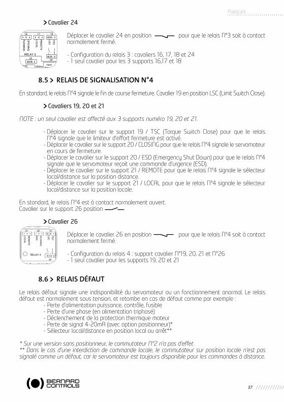
Cavalier 24
Déplacer le cavalier 24 en position pour que le relais N°3 soit à contact normalement fermé.
- Configuration du relais 3 : cavaliers 16, 17, 18 et 24- 1 seul cavalier pour les 3 supports 16,17 et 18
8.5 RELAIS DE SIGNALISATION N°4
En standard, le relais N°4 signale le fin de course fermeture. Cavalier 19 en position LSC (Limit Switch Close).
Cavaliers 19, 20 et 21
NOTE : un seul cavalier est affecté aux 3 supports numéro 19, 20 et 21.
- Déplacer le cavalier sur le support 19 / TSC (Torque Switch Close) pour que le relais N°4 signale que le limiteur d’effort fermeture est activé.
- Déplacer le cavalier sur le support 20 / CLOSING pour que le relais N°4 signale le servomoteur en cours de fermeture.
- Déplacer le cavalier sur le support 20 / ESD (Emergency Shut Down) pour que le relais N°4 signale que le servomoteur reçoit une commande d’urgence (ESD).
- Déplacer le cavalier sur le support 21 / REMOTE pour que le relais N°4 signale le sélecteur local/distance sur la position distance.
- Déplacer le cavalier sur le support 21 / LOCAL pour que le relais N°4 signale le sélecteur local/distance sur la position locale.
En standard, le relais N°4 est à contact normalement ouvert. Cavalier sur le support 26 position
Cavalier 26
Déplacer le cavalier 26 en position pour que le relais N°4 soit à contact normalement fermé.
- Configuration du relais 4 : support cavalier N°19, 20, 21 et N°26- 1 seul cavalier pour les supports 19, 20 et 21
8.6 RELAIS DÉFAUT
Le relais défaut signale une indisponibilité du servomoteur ou un fonctionnement anormal. Le relais défaut est normalement sous tension, et retombe en cas de défaut comme par exemple : - Perte d’alimentation puissance, contrôle, fusible - Perte d’une phase (en alimentation triphasé) - Déclenchement de la protection thermique moteur - Perte de signal 4-20mA (avec option positionneur)* - Sélecteur local/distance en position local ou arrêt**
* Sur une version sans positionneur, le commutateur N°2 n’a pas d’effet.** Dans le cas d’une interdiction de commande locale, le commutateur sur position locale n’est pas signalé comme un défaut, car le servomoteur est toujours disponible pour les commandes à distance.

38
Commutateur 2
Basculer le commutateur 2 sur la position B pour que la perte du signal 4-20mA ne soit pas un défaut. (Option positionneur seulement).
- La perte du signal 4-20mA n’est pas un défaut. (Option positionneur seu-lement).
Commutateur 3
Basculer le commutateur 3 sur la posi-tion B pour que le commutateur local/distance sur local ou arrêt ne soit pas un défaut.
- le commutateur local/distance sur local ou arrêt n’est pas un défaut.
Commutateur 12
Basculer le commutateur 12 sur la position B pour qu’un déclenchement du limiteur d’effort fermeture soit un défaut.
- Un déclenchement du limiteur d’effort fermeture est un défaut
Commutateur 13
Basculer le commutateur 13 sur la position B pour que un déclenchement du limiteur d’effort ouverture soit un défaut.
- Un déclenchement du limiteur d’effort ouverture est un défaut.
Remarque : Le système de surveillance est capable de détecter si la vanne se ferme sur limiteur d’effort et dans ce cas n’indique pas de défaut.

INTEGRAL+ / POSIGAM +
Fast set up
Adjustment of POSIGAM+
Put back the ‘potentiometer’ board on the camblock axis (if it has been dismounted for cam adjustment).
Plug a milliamp-meter between terminals 31 and 32 to measure the position feedback.
31(-) and 32(+)
Open the control box of the actuator to find the positioner board (also called GAM-K)
This board is located at 90 ° of the local command.
Set the red knob on REMOTE position Local command is now impossible
Set the selector to 0%. The actuator will receive a closure command (equivalent to 4mA command).
Actuator is running is closing direction
Case N°1: The actuator runs in closing direction and stops before reaching the limit switch. Turn the actuator’s potentiometer gradually to bring the actuator on the limit switch. Then turn slowly the potentiometer in reverse up to turn the red light off.
The 0% is now synchronized.
Check the position signal measured between 31 and 32(4mA depending on the configuration)
Case N°2: The actuator runs in closing direction and stops on the limit switch and the red ‘close’ light remains ON.Slowly turn the actuator’s potentiometer up to turn the red light off.
Set the selector to 100%. The actuator will receive an order for opening (equivalent to 20mA command).
Actuator is running is opening direction
Case N°1: The actuator runs in opening direction and stops before reaching the limit switch. Adjust the board potentiometer “ADJ 100%” gradually in CW direction to bring the actuator on the limit switch.Slowly turn the board potentiometer in CCW direction to turn the green light off.
ADJ100%
The 100% is now synchronized.
Check the position signal measured between 31 and 32(20mA depending on the configuration)
Case N°2: The actuator runs in opening direction and stops on the limit switch and the green ‘open’ light remains ON.Turn slowly the board potentiometer “ADJ 100%” in CCW direction to turn the green light off.
Check the repeatability of the setting by several strokes 0% > 100% then set the selector to AUTO
Set-up is completed
Détachable / D
etachable

PRISE EN MAIN RAPIDE INTEGRAL+ / POSIGAM+Le servomoteur est raccordé électriquement sur la partie puissance 0/1/Terre en monophasé, 1/2/3/Terre en triphasé.Il est raccordé mécaniquement à la vanne (ou ventelle) à actionner.
DESCRIPTION AFFICHAGE COMMENTAIRES
Réglage des fins de course POSIGAM+ et réglage complet INTEGRAL+
Mettre le sélecteur sur position LOCAL
Si actionneur ¼ tour (ou actionneur multitours monté sur réducteur ¼ de tour). Desserrer les 2 vis de butée: - A l’aide d’une clef plate : desserrer le contre-écrou- A l’aide d’une clef hexagonale : desserrer la butée
de 2 tours
Clef plateClef hexagonale
A l’aide le commande locale (ou du volant), atteindre la position ‘fermé’ de la vanne
Ajuster la came si nécessaire (repère blanc) pour augmenter ou diminuer la course. Pour un meilleur accès, la carte ‘potentiomètre’ fixée sur le bloc de cames peut être temporairement démontée.
Faire des aller-retour à l’aide de la commande locale entre deux ajustements
A l’aide le commande locale (ou du volant), atteindre la position ‘Ouverture 100%’ de la vanne
Ajuster came si nécessaire (repère noir) pour augmenter ou diminuer la course.
Faire des aller-retour à l’aide de la commande locale entre deux ajustements
Sur actionneur ¼ de tour :- Resserrer la vis de butée ‘ouverture’ jusqu’à
atteindre le secteur et puis dévisser de 1,5 tour - Resserrer le contre-écrou en maintenant la vis
de butée
Fermer la vanne et effectuer l’opération similaire sur la butée de fermeture : Atteindre le secteur et desserrer de 1,5 tour, resserrer le contre-écrou
Pour effectuer les autres paramétrages spécifiques, merci de vous reporter à la notice détaillée NR1088

Français
INTEGRAL+ / POSIGAM +
Prise en main rapide
Réglage POSIGAM+
Remonter la carte potentiomètre sur l’axe du bloc de cames si elle a été démontée lors du réglage des cames de fin de course.
Brancher un milliampèremètre sur les bornes 31 et 32.
31(-) et 32(+)
Ouvrir le boitier pour voir apparaitre la carte du positionneur (GAM-K)
Cette carte est située à 90° de la commande locale.
Mettre le sélecteur rouge sur position REMOTE La commande locale devient impossible
Basculer le commutateur de commande manuelle sur la position 0% pour que le servomoteur reçoive un ordre de fermeture (équivalent à 4mA).
Rotation en sens ‘Fermeture’
Cas N°1: Le servomoteur part en fermeture et s’arrête sans actionner le contact de fin de course fermeture. Tourner le potentiomètre du servomoteur progressivement pour amener le servomoteur sur le contact de fin de course, voyant allumé. Tourner lentement le potentiomètre en sens inverse jusqu’à éteindre le voyant rouge.
Le 0% est synchronisé.
Vérifier le signal de recopie mesuré entre les bornes 31 et 32 (4mA variable selon réglage)
Cas N°2: Le servomoteur part en fermeture, s’arrête sur le fin de course fermeture et le voyant de fermeture est toujours allumé. Tourner le potentiomètre du servomoteur progressivement pour éteindre le voyant de fermeture.
Basculer le commutateur de commande manuelle sur la position 100% pour que le servomoteur reçoive un ordre d’ouverture (20mA).
Rotation en sens ‘Ouverture’
Cas N°1: Le servomoteur part en ouverture et s’arrête avant le fin de course ouverture. Ajuster le potentiomètre situé sur la carte ‘positionneur’ “ADJ 100%” (réglage du 100%) progressivement sens horaire jusqu’à amener le servomoteur sur le fin de course ouverture.Tourner lentement ce potentiomètre en sens antihoraire jusqu’à éteindre le voyant vert.
ADJ100%
Le 100% est synchro-nisé
Vérifier que le signal de recopie est conforme aux valeurs attendues (4-20mA)
Cas N°2: Le servomoteur part en ouverture, s’arrête sur le fin de course ouverture, et le voyant vert est toujours allumé. Tourner le potentiomètre situé sur la carte ‘positionneur’ “ADJ 100%” (réglage du 100%) progressivement sens antihoraire pour éteindre le voyant vert.
Vérifier la répétabilité du réglage par plusieurs manœuvres 0% > 100% puis replacer le sélecteur sur AUTO
Le réglage est terminé.

FAST SET-UP INTEGRAL+ / POSIGAM+The actuator is connected to the main supply: 0/1/Earth with single-phase, 1/2/3/Earth with 3-phase voltage.The assembly with the valve (or damper) has been already done.
DESCRIPTION VIEW COMMENTS
Adjustment of the limit switches for POSIGAM+, full set-up for INTEGRAL+
Set the red knob on LOCAL position
In case of quarter-turn actuator (or multiturn actuator mounted on quarter-turn gearbox): loosen the 2 mechanical stop screws: - Using a spanner : Loosen the 2 nuts- Using hexagonal key: Loosen the 2 stop screws
of two turns
SpannerHex key
Using the local command (or the handwheel), reach the ‘closed’ position of the valve.
Adjust the cam (white marking) to increase or decrease the stroke. For a better access to the cam , it is possible to remove the ‘potentiometer’ board fixed over the camblock.
Open/Close using the local command between two adjust-ments
Using the local command (or the handwheel), reach the ‘open’ position of the valve.
Adjust the cam (black marking) to increase or decrease the stroke.
Open/close using the local command between two adjust-ments
For quarter-turn actuators :- Screw the ‘open’ mechanical stop screw until it
touches the quadrant and unscrew by 1,5 turn. - Tighten the nut to lock the mechanical stop.
SpannerHex key
Close the valve and do the same operation with the ‘closed’ mechanical stop : Reach the quadrant and unscrew by 1,5 turn, tighten the nut to lock the mechanical stop.
To perform other specific settings, please refer to the detailed manual NR1088.
Dét
acha
ble
/ D
etac
habl
e

39
Français
9 PROTECTION FUSIBLES
Accessibilité : - Mettre le servomoteur hors tension. - Déposer le couvercle avec les boutons de contrôle. Faire attention aux câbles à l’intérieur
du couvercle. - Dévisser les bouchons des supports de fusible et changer les fusibles si nécessaire..
Caractéristiques des fusibles :FU1 : fusible primaire transformateur 6,3 x 32mm - 0,5A - 500VFU2 : fusible secondaire transformateur 5 x 20mm - 0,5AFU3 : fusible secondaire transformateur 5 x 20mm - 0,05A
10 OPTION POSITIONNEUR
Un positionneur permet d’atteindre une position proportionnelle à un signal de commande. Le panneau de configuration permet: - De faire des commandes de positionnement local - D’adapter le servomoteur au signal d’entrée - De configurer la réaction du servomoteur en cas de perte de signal d’entrée
10.1 CONFIGURATION DU SIGNAL D’ENTRÉE
Le standard est un signal d’entrée de 4-20mA
10.1.1 Utilisation d’un signal 0-20mA
Commutateurs 4 et 8Basculer les commutateurs 4 et 8 sur la position B pour un signal d’entrée 0-20mA. La recopie de position est aussi en 0-20mA.
10.1.2 Utilisation d’un signal 0-10V
Commutateur 4, 8, 9 et 10Basculer les commutateurs 4, 8, 9 et 10 sur la position B pour utiliser un signal 0-10V. La recopie de position est en 0-20mA.
10.2 CONFIGURATION DU SENS DE MANOEUVRE
Le standard est 4 mA vanne fermée et 20mA vanne ouverte.
Commutateur 3
Connexion du potentiomètreBasculer le commutateur 3 sur la position B, et déplacer la connexion du potentiomètre du servomoteur de la position “POT STD” à “POT REV” pour avoir 4mA vanne ouverte et 20mA vanne fermée.

40
10.3 CONFIGURATION DE LA FONCTION SEUIL
Avec un signal d’entrée 4-20mA, il est possible de configurer une position de repli en cas de coupure de signal de commande. En standard, la fonction est active, et le servomoteur reste en position en cas de perte du signal.
Commutateurs 5, 6 et 8Basculer le commutateur 5 sur la position B pour que le servomoteur s’ouvre en cas de perte du signalBasculer le commutateur 6 sur la position B pour que le servomoteur se ferme en cas de perte de signalBasculer le commutateur 8 sur la position B pour désactiver la fonction seuil.
10.4 RÉGLAGE DE LA BANDE MORTE
Ce réglage est fait en usine, mais il est possible d’ajuster par action sur le potentiomètre“BANDE MORTE”. Pour réduire la bande morte tourner en sens antihoraire.
10.5 MANOEUVRE LOCALE
Il est possible de simuler un signal de consigne 4-20mA en local pour vérifier le fonctionnement du servomoteur.
- AUT : Commande par signal externe- 0% : Signal interne 0% (4mA en standard)- MAN : Signal interne réglable de 0 à 100%- 100 % : Signal interne 100% (20mA en standard)
Basculer le commutateur de commande locale sur la 0%,MAN ou 100%. Tourner le potentiomètre “MAN” pour simuler un signal 4-20mA.
Configuration du sens de manoeuvre
Définition dusignal d’entrée
Ouverture 4mA 20mA 0mA 20mA 0v 10V
Fermeture 4mA 20mA 0mA 20mA 0v 10V
Action de la vanne
Fermeture sens horaire
Fermeture sens anti-horaire
Fermeture sens horaire
Fermeture sens anti-horaire
Configuration Standard
Carte CI2701 :commutateur 7 sur B
Potentiomètre inversé
GAMK board:switch 3 on B
Reverse potentio-meter
Carte CI2701 :commutateur 7 sur B
Carte GAMK :commutateur 3 sur B
Attention : dans le cas d’un signal d’entré 0-20mA ou 0-10V, La fonction seuil ne peut pas être utilisée et doit être désactivée. Basculer le commutateur 8 sur la position B.
Attention : Une réduction trop importante de la bande morte amènera un “pompage” du servomoteur.

41
Français
10.6 RÉGLAGE DU 0%
Basculer le commutateur de commande manuelle sur la position 0% pour que le servomoteur reçoive un ordre de fermeture (4mA).
Cas N°1: le servomoteur part en fermeture et s’arrête avant le fin de course fermeture. Tourner le potentiomètre du servomoteur progressivement pour amener le servomoteur
sur le fin de course fermeture, voyant allumé. Tourner lentement le potentiomètre en sens inverse jusqu’à étendre le voyant rouge.
Cas N°2: le servomoteur part en fermeture, s’arrête sur le fin de course fermeture, et le voyant de fermeture est toujours allumé.
Tourner le potentiomètre du servomoteur progressivement pour éteindre le voyant de fermeture.
10.7 RÉGLAGE DU 100%
Basculer le commutateur de commande manuelle sur la position 100% pour que le servomoteur reçoive un ordre d’ouverture (20mA).
Cas N°1: le servomoteur part en ouverture et s’arrête avant le fin de course ouverture. Actionner le potentiomètre “ADJ 100%” (réglage du 100%) progressivement sens horaire
jusqu’à amener le servomoteur sur le fin de course ouverture. Tourner lentement ce poten-tiomètre en sens inverse jusqu’à éteindre le voyant vert.
Cas N°2: le servomoteur part en ouverture, s’arrête sur le fin de course ouverture, et le voyant vert est toujours allumé.
Tourner le potentiomètre “ADJ 100%” (réglage du 100%) progressivement sens antihoraire pour éteindre le voyant vert.
10.8 LES COMMANDES FRACTIONNÉES
La carte positionneur peut se configurer pour des commandes fractionnées.
On appelle commandes fractionnées les signaux d’entrée 4-12mA et 12-20mA. Le signal de l’utili-sateur est normal: 4-20mA. Un premier servomoteur est prévu pour recevoir un signal de 4 à 12mA et un deuxième est prévu pour recevoir un signal de 12 à 20mA. Chaque servomoteur reçoit le signal 4-20mA. Le premier s’ouvre complètement de 0 à 50% du signal et le second de 50 à 100% du signal.
Commutateurs 1 et 2Basculer le commutateur 1 sur la position B pour que le servomoteur reçoive une commande fractionnée 12-20mA.Basculer le commutateur 2 sur la position B pour que le servomoteur reçoive une commande fractionnée 4-12mA.
42
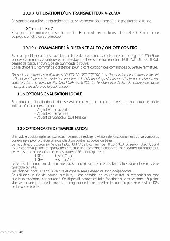
10.9 UTILISATION D’UN TRANSMETTEUR 4-20MA
En standard on utilise le potentiomètre du servomoteur pour connaître la position de la vanne.
Commutateur 7Basculer le commutateur 7 sur la position B pour utiliser un transmetteur 4-20mA à la place du potentiomètre du servomoteur.
10.10 COMMANDES À DISTANCE AUTO / ON-OFF CONTROL
Avec un positionneur, il est possible de faire des commandes à distance par un signal 4-20mA ou par des commandes ouverture/fermeture/stop. L’entrée sur le bornier client AUTO/ON-OFF CONTROL permet de basculer d’un type de commande à l’autre.Voir le chapitre 5 “commande à distance” pour la configuration des commandes ouverture fermeture.
Nota : les commandes à distances “AUTO/ON-OFF CONTROL” et “Interdiction de commande locale” utilisent la même entrée sur le bornier client. L’installation du positionneur affecte automatiquement cette entrée à la fonction AUTO/ON-OFF CONTROL. La fonction interdiction de commande locale n’est pas utilisable avec le positionneur.
11 OPTION SIGNALISATION LOCALE
En option une signalisation lumineuse visible à travers un hublot au niveau de la commande locale indique l’état du servomoteur. - Voyant vanne ouverte - Voyant vanne fermée - Voyant servomoteur sous tension
12 OPTION CARTE DE TEMPORISATION
Un module additionnelle temporisateur permet de réduire la vitesse de fonctionnement du servomoteur, par exemple pour protéger une canalisation contre les coups de bélier.Ce module est raccordé sur l’entrée P202TEMPO de la commande INTEGRALE+ du servomoteur. Quand l’ordre est envoyé, une temporisation effectue une commande cadencée marche/arrêt du contacteur. Le temps de marche ON et le temps d’arrêt OFF sont réglables : T.ON : 0,5 à 10 sec T.OFF : 3 sec à 2 mnLe temps de manoeuvre de la pleine course peut ainsi atteindre des temps très longs et de plus être ajustable sur site.Les réglages dans le sens Ouverture et dans le sens Fermeture sont indépendants.En utilisant un fin de course auxiliaire, il est possible de court-circuiter la temporisation tant que le microcontact est actionné. Ce dispositif permet de faire fonctionner le servomoteur à pleine vitesse sur une partie de la course. La longueur de la came de fin de course représente environ 10% de la course totale.

43
Français
CYCLE DE FONCTIONNEMENT1/ Contact auxiliaire ouverture.2/ Contact auxiliaire fermeture.3/ Ouverture lente.4/ Ouverture rapide.5/ Fermeture rapide.6/ Fermeture lente.7/ Réglage du temps d’arrêt sens ouverture.8/ Réglage du temps de marche sens ouverture.9/ Réglage du temps de marche sens fermeture.10/ Réglage du temps d’arrêt sens fermeture.11/ Connexion des contacts auxiliaires éventuels12/ Connexion de la carte INTEGRAL+.
Open
Close Time
1 4 5
3
2 6

44
PROBLEME CAUSE REMEDE
Rien ne fonctionne Alimentation du servomoteur
Vérifier la tension d’alimentation (bornes 1, 2, 3 en triphasé ou 0,1 en monophasé). La tension est indiquée sur la plaque signalétique.
Un ordre d’interdiction de commande locale est présent.
Vérifier que le servomoteur ne reçoit pas une interdiction de commande locale.Hors exploitation, on peut éventuellement retirer le fil d’interdiction de commande locale, raccordé borne 11 pour vérifier le fonctionnement du servomoteur.
Un ordre commande d’urgence est présent et interdit toute autre commande.
Vérifier que le servomoteur ne reçoit pas une commande d’urgence.Hors exploitation, on peut éventuellementretirer le cavalier N°27 de la carte CI2701 en prenant la précaution de bien noter sa position pour le replacer dans la bonne position. Cavalier retiré, la fonction ESD est supprimée, ce qui permet de vérifier le fonctionnement du servomoteur. Remettre le cavalier en place.
Fusible coupé. Vérifier l’état des fusibles et les remplacer si nécessaire.
Configuration du typed’alimentation.
Vérifier la position du cavalier 100 de la carteCI2701En triphasé position TEn monophasé ou CC position M
Déclenchement protection thermique moteur
Le voyant TH sur le panneau de configuration de la carte CI2701 indique la présence d’un déclenchement thermique. Le servomoteur sera de nouveau disponible après refroidissement du moteur.
Le volant débrayable de commande manuelle est resté enclenché (uniquement version avec contact de sécurité électrique).
Vérifier que le volant est bien en position débrayée.
Des cavaliers de configurations s ont mal positionnés ou manquants
Il doit y avoir 11 cavaliers sur la carte CI2701Il ne doit y avoir qu’un seul cavalier sur le groupe de support cavalier 16-17-18 et un seul cavalier sur le groupe de support cavalier 19-20-21.
13 RESOLUTION DE PROBLEMES SUR LA VERSION INTEGRAL+
Si le fonctionnement de l’appareil semble douteux, placer en premier lieu le sélecteur local/distance sur la position locale, et agir sur les commandes ouverture et fermeture.

45
Français
PROBLEME CAUSE REMEDE
Le servomoteur fonctionne en local mais pas à distance
Sélecteur local/distance sur local ou off (arrêt)
Set the local/remote selector switch to remote.
Commande par contact : pas de tension entre les bornes 6 et 7.
Vérifier qu’il existe un shunt au bornier client entre les bornes 5 et 6.Vérifier le fusible FU3 de la carte CI2701
Commande par tension : tension non adaptée à l’entrée.
Vérifier le raccordement en commande par tension :Tension de 10 à 55 Volt : Bornier 5Tension de 90 à 250 Volt : Bornier 4
Le servomoteur fonctionne en distance mais pas en local
Sélecteur local/distance sur distance ou off (arrêt)
Basculer le sélecteur local / distance sur la position locale
Un ordre d’interdiction de commande locale est présent
Vérifier que le servomoteur ne reçoit pas une interdiction de commande locale.Hors exploitation, on peut éventuellement retirer le fil d’interdiction de commande locale, raccordé borne 11 pour vérifier le fonctionnement du servomoteur.
Le servomoteur ne tourne pas dans le bon sens de rotation.
Configuration non adaptée.
Vérifier la configuration du sens de rotationCommutateur N°7 de la carte CI2701 :Position A : fermeture sens horairePosition B : fermeture sens anti-horaire
Le moteur à été décablé et tourne en sens inverse (changement de moteur par exemple)
Lors d’un changement de moteur, il faut respecter les repères des fils. En cas de doute, vérifier la conformité du sens de rotation. L’inversion de sens de rotation du moteur se fait en permutant les fils 2 et 3 du bornier moteur dans le compartiment des connexions.
Le servomoteur ne s’arrête pas sur le fin de course fermeture.
Le servomoteur est configuré pour se fermer sur couple
Vérifier la configuration de fermeture (commutateur 1 de la carte CI2701)
Le fin de course fermeture est mal réglé.
Régler le fin de course fermeture. Le fin de course fermeture doit être actionné vanne fermée (même si le servomoteur ferme sur couple)
Le moteur a été décablé et tourne en sens inverse (changement de moteur)
Lors d’un changement de moteur, il faut res-pecter les repères des fils. En cas de doute, vérifier la conformité du sens de rotation.L’inversion de sens de rotation du moteur se fait en permutant les fils 2 et 3 du bornier moteur dans le compartiment des connexions.

46
PROBLEM CAUSE CORRECTIVE ACTION
Rien ne fonctionne Un ordre commande d’urgence est présent et interdit toute autre commande.
Vérifier que le servomoteur ne reçoit pas une commande d’urgence.Hors exploitation, on peut éventuellement retirer le cavalier N°27 de la carte CI2701 en prenant la précaution de bien noter sa position pour le replacer dans la bonne position. Cavalier retiré, la fonction ESD est supprimée, ce qui permet de vérifier le fonctionnement du servomoteur.Remettre le cavalier en place.
14 RESOLUTION DE PROBLEMES SUR LA VERSION POSITIONNEUR
Si le fonctionnement de l’appareil semble douteux, placer en premier lieu le sélecteur local/distance sur la position locale, et agir sur les commandes ouverture et fermeture locales.
PROBLEME CAUSE REMEDE
Le servomoteur ne s’arrête pas sur le fin de course ouverture
Le fin de course ouverture est mal réglé
Régler le fin de course ouverture. Il doit être actionné vanne ouverte
Le moteur a été décablé et tourne en sens inverse (changement de moteur)
Lors d’un changement de moteur, il faut res-pecter les repères des fils. En cas de doute, vérifier la conformité du sens de rotation.L’inversion de sens de rotation du moteur se fait en permutant les fils 2 et 3 du bornier moteur dans le compartiment des connexions.
Aucune signalisation Servomoteur hors tension Les signalisations ne sont disponibles que servomoteur sous tension
Aucune signalisation des limiteurs d’efforts
Mauvaise configuration Vérifier que le relais de signalisation concerné a été configuré en signalisation limiteur d’effort. Le cavalier de la carteCI2701 est sur :TSO pour limiteur d’effort ouvertureTSC pour limiteur d’effort fermeture
Le limiteur d’effort a été sollicité manuellement
L’électronique ne mémorise les limiteurs d’effort que si une manoeuvre est en cours et que celui correspondant au sens de rotation en cours.
Signalisation limiteur d’effort reste activée quand le limiteur d’effort n’est plus actionné
Mémorisation du limiteur d’effort
Les limiteurs d’effort sont mémorisés électroniquement.Pour démémoriser un limiteur d’effort, il est nécessaire d’envoyer un ordre inverse.

47
Français
PROBLEM CAUSE CORRECTIVE ACTION
Rien ne fonctionne Fusible coupé Vérifier l’état des fusibles de la carte CI2701.
Configuration du type d’alimentation.
Vérifier la position du cavalier 100 de la carte CI2701 : en triphasé position T, en monophasé ou CC position M
Déclenchement protection thermique moteur
Le voyant TH sur le panneau de configura-tion de la carte CI2701 indique la présence d’un déclenchement thermique. Le servo-moteur sera de nouveau disponible après refroidissement du moteur.
Le volant débrayable de commande manuelle est resté enclenché (uniquement version avec contact de sécurité électrique).
Vérifier que le volant est bien en position débrayée.
Des cavaliers de configu-rations sont mal position-nés ou manquants
Il doit y avoir 11 cavaliers sur la carte CI2701 Il ne doit y avoir qu’un seul cavalier sur le groupe de support cavalier 16-17-18 et un seul cavalier sur le groupe de supports cavalier 19-20-21.
Le servomoteur fonc-tionne en commande ouverture / fermeture locale, mais pas en positionneur
Sélecteur local / distance sur local ou arrêt
Basculer le sélecteur local / distance sur la position distance pour utiliser le position-neur. (Même lorsque le positionneur est sur position manuelle)
Un ordre Auto / on-off control est présent et interdit l’utilisation du positionneur
Vérifier que le servomoteur ne reçoit pas de commande Auto / on-off. Eventuellement, tester en débranchant le fil de la borne 11.
Problème de connexion entre cartes CI2701 et positionneur (GAM-K)
Vérifier la liaison GAM-K - carte CI2701.
Potentiomètre de recopie du servomoteur mal positionné
Tourner le potentiomètre du servomoteur d’un quart de tour et reprendre les essais suivant la notice de mise en service.
Mauvaise adaptation au signal d’entrée.
Vérifier la configuration sur la carte positionneur:Signal entrée 4-20mA :Commutateurs 4, 8, 9, 10 sur ASignal entrée 0-20mA :Commutateurs 4, 8 sur BCommutateurs 9, 10 sur ASignal entrée 0-10V :Commutateurs 4, 8, 9, 10 sur B

48
PROBLEM CAUSE CORRECTIVE ACTION
Le servomoteur ne suit pas le signal d’entrée
Potentiomètre inversé La connexion du potentiomètre est sur la position POT STD pour:• 4mA (ou 0mA ou 0V suivant le signal) = position fermée et fermeture sens horaire• 4mA (ou 0mA ou 0V suivant le signal) = posi-tion ouverte et fermeture sens anti-horaireLa connexion du potentiomètre doit être sur laposition POT REV pour:• 4mA (ou 0mA ou 0V suivant le signal) = position fermée et fermeture sens antihoraire-• 4mA (ou 0mA ou 0V suivant le signal) = position ouverte et fermeture sens horaire
Signal inversé ou mauvaise configuration
Vérifier la configuration du signal.Commutateur N°3 sur carte positionneurPosition A : 4mA = vanne ferméePosition B : 4mA = vanne ouverte
Sens de rotation inversé Vérifier la configuration du sens de rotationCommutateur N°7 sur la carte INTEGRAL+ :Position A : fermeture sens horairePosition B : ouverture sens anti-horaire
Potentiomètre de recopie du servomoteur mal positionné
Tourner le potentiomètre de 1/4 de tour et reprendre les réglages suivant la notice de mise en service.
Le moteur a été décablé et tourne en sens inverse (changement de moteur)
En cas de doute, vérifier la conformité du sens de rotation. L’inversion de sens de rotation du moteur se fait en permutant les fils 1 et 2 du bornier moteur dans le compartiment des connexions.
Le commutateur Auto - 0% - 100% n’est pas en position Auto
Vérifier la position du commutateur Auto - 0% - 100% sur la carte positionneur
Signal défectueux. Vérifier le signal de consigne avec un milliampèremetre branché en série (borne 30)
Polarité du signal Vérifier que le positif (+) du signal arrive sur la borne 30. Vérifier la connexion du potentiomètre.
Le servomoteur ne s’arrête pas sur le fin de course fermeture.
Le servomoteur est confi-guré pour se fermer sur coupled.
Vérifier la configuration de fermeture (commutateur 1 sur carte CI2701)
Le fin de course fermeture est mal réglé.
Régler le fin de course fermeture. Le fin de course fermeture doit être actionné vanne fermée (même si le servomoteur ferme sur couple)
La position 0% est mal réglée
Réglage du potentiomètre du servomoteur

49
Français
PROBLEM CAUSE CORRECTIVE ACTION
Le servomoteur ne s’arrête pas sur le fin de course fermeture.
Le moteur a été décablé et tourne en sens inverse (changement de moteur)
En cas de doute, vérifier la conformité du sens de rotation. L’inversion de sens de rotation du moteur se fait en permutant les fils 1 et 2 du bornier moteur dans le compar-timent des connexions.
Le servomoteur ne s’arrête pas sur le fin de course ouverture
Le fin de course ouverture est mal réglé
Régler le fin de course ouverture. Le fin de course ouverture doit être actionné vanne ouverte.
La position 100% est mal réglée
Réglage du potentiomètre 100% de la carte positionneur
Le moteur a été décablé et tourne en sens inverse (changement de moteur)
Lors d’un changement de moteur, il faut res-pecter les repères des fils. En cas de doute, vérifier la conformité du sens de rotation.L’inversion de sens de rotation du moteur se fait en permutant les fils 1 et 2 du bornier moteur.
Aucune signalisation des limiteurs d’effort
Mauvaise configuration Vérifier que le relais de signalisation concerné a été configuré en signalisation limiteur d’effort.Le cavalier de la carte INTEGRAL+ est sur :TSO pour limiteur d’effort ouvertureTSC pour limiteur d’effort fermeture
Le limiteur d’effort a été sollicité manuellement
L’électronique ne mémorise les limiteurs d’effort que si une manoeuvre est en cours. Elle ne mémorise de plus que le limiteur d’effort correspondant au sens de rotation.
Aucune signalisation Servomoteur hors tension Les signalisations ne sont disponibles que servomoteur sous tension
Signalisation limiteur d’effort reste activée quand le limiteur d’effort n’est plus actionné
Mémorisation du limiteur d’effort
Les limiteurs d’effort sont mémorisés électroniquement.Pour démémoriser un limiteur d’effort, il est nécessaire d’envoyer un ordre inverse.
Signalisation défaut alors que le servo-moteur fonctionne normalement
Le signal de consigne n’est pas présent. En standard, le servomoteur signale un défaut et reste en position
Envoyer un signal de commande sur l’entrée
Le sélecteur est sur la position local ou off . En standard, le servomoteur signale un défaut.
Mettre le sélecteur sur la position distance

50
15 USER’S SETTINGS / CONFIGURATION UTILISATEUR (*)
(*) Circle or highlight the options corresponding to your system settings Cerclez ou surlignez les valeurs correspondant à la configuration de votre système.
INTEGRAL+ (CI2701)
Jum
pers
& S
wit
ches
/ C
aval
iers
& C
omm
utat
eurs
1 A B
2 A B
3 A B
4 A B
5 A B
6 A B
7 A B
8 A B
9 A B
10 A B
11 A B
12 A B
13 A B
14 LSO TSO
15 LSC TSC
16/17/18 LSO TSO Local Remote Running Opening
19/20/21 LSC TSC ESD Closing Local Remote
22
23
24
25 50 200
26
27
28 close open
POSITIONER GAM-K
1 A B
2 A B
3 A B
4 A B
5 A B
6 A B
7 A B
8 A B
9 A B
10 A B

51
Deutsch
SCHALTPLANDRAWINGS Page 3
1 EINLEITUNG Page 522 SCHNELLES VENTIL-SET-UP Page 523 KONFIGURATION Page 524 SPANNUNGSVERSORGUNG Page 52 4.1 Spannungsversorgung des Antriebs Page 52 4.2 Spannungsversorgungsausgang Page 535 ARBEITSWEISE DES ANTRIEBS Page 53 5.1 Drehrichtung Page 53 5.2 Weg- oder Drehmomentabhängiges Abschalten Page 53 5.3 Drehmomentüberbrückung beim Anfahren Page 54 5.4 Reversierzeit Page 546. FERNSTEUERUNG Page 54 6.1 Ansteuern mit potentialfreien Kontakten Page 55 6.2 Ansteuerung mit externer Steuerspannung Page 55 6.3 Ansteuern mit nur einem Kontakt Page 55 6.4 Vorrang für AUF oder ZU Page 56 6.5 Notfahrbefehl (ESD) Page 56 6.6 Ortssteuerstelle verriegeln / blockieren Page 577. ORTSSTEUERSTELLE Page 58 7.1 Selbsthaltung Page 58 7.2 Stopp-Funktion Page 58 7.3 Not-Ausschaltung (OFF) Page 58 7.4 Abschliessbarer Ort-/Fern-Umschalter Page 598 MELDUNGEN Page 59 8.1 Blinkgeber Page 59 8.2 Meldung Relais 1 Page 60 8.3 Meldung Relais 2 Page 60 8.4 Meldung Relais 3 Page 60 8.5 Meldung Relais 4 Page 61 8.6 Alarmrelais Page 619 SICHERUNG Page 6310 ZUBEHÖR-POSITIONER Page 63 10.1 Eingangssignal-Einstellung Page 63 10.1.1 Betrieb mit Eingangssignal 0-20 mA Page 63 10.1.2 Betrieb mit Eingangssignal 0-10 V Page 63 10.2 Einstellung der Arbeitsweise (Drehrichtung) Page 63 10.3 Einstellung der ‘’STAY-PUT”-Funktion Page 64 10.4 Totband Page 64 10.5 Probebetrieb vor Ort Page 64 10.6 0%-Einstellung Page 65 10.7 100%-Einstellung Page 65 10.8 Split range (Geteiltes Signal) Page 65 10.9 Stellungsabfrage mit elektronischem Stellungsrückmelder TAM 4-20mA Page 66 10.10 Fernansteuerung AUTO-/EIN-AUS Steuerung Page 6611 ZUBEHÖR : TAKTGEBER Page 6612 ZUBEHÖR : MELDELEUCHTEN Page 6613 WAS TUN WENN ... MÖGLICHE FUNKTIONSFEHLER BEI DER INTEGRAL-PLUS Page 6814 WAS TUN WENN ... MÖGLICHE FUNKTIONSFEHLER BEI POSIGAM-/MODUGAM-PLUS Page 7115 BENUTZEREINSTELLUNGEN Page 75
INHALT
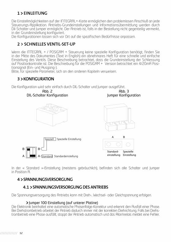
52
1 EINLEITUNG
Die Einstellmöglichkeiten auf der INTEGRAL+-Karte ermöglichen den problemlosen Anschluß an jede Steuerungs-Applikation. Antriebs-Grundeinstellungen und Informationsübermittlung werden durch Dil-Schalter und Jumper ermöglicht. Der Antrieb ist, falls in der Bestellung nicht gegenteilig vermerkt, in der Grundeinstellung konfiguriert.Die Konfigurationen lassen sich vor Ort auf die spezifischen Bedürfnisse anpassen.
2 > SCHNELLES VENTIL-SET-UP
Wenn die INTEGRAL + / POSIGAM + Steuerung keine spezielle Konfiguration benötigt, finden Sie in der Mitte des Dokumentes (Text in English) ein abnehmares Heft für eine schnelle und einfache Einstellung des Ventils. Diese Beschreibung betrachtet, dass die Grundeinstellung der Schliessung auf Positionkontrolle ist. Die Beschreibung für die POSIGAM + Version betrachtet ein 4/20mA Posi-tionsignal (Ein- und Ausgang-).Bitte, für spezielle Parameter, sich an den anderen Kapiteln verweisen.
3 KONFIGURATION
Die Konfiguration wird sehr einfach durch DIL-Schalter und Jumper ausgeführt.
In der « Standard »-Einstellung (meistens gebräuchlich), befinden sich alle Schalter und Jumper in Position A.
4 SPANNUNGSVERSORGUNG
4.1 SPANNUNGSVERSORGUNG DES ANTRIEBS
Die Spannungsversorgung des Antriebs kann mit Dreh-, Wechsel- oder Gleichspannung erfolgen.
Jumper 100 Einstellung (auf unterer Platine)Die Elektronik beinhaltet eine automatische Phasenfolge-Korrektur und erkennt den Ausfall einer Phase. Bei Drehstrombetrieb arbeitet der Antrieb dadurch immer mit der korrekten Drehrichtung. Falls bei Drehs-trombetrieb eine Phase ausfällt, stoppt der Antrieb automatisch und das Alarmrelais meldet eine Fehler.
Abb. 2DIL-Schalter Konfiguration
Abb. 3Jumper Konfiguration

53
Deutsch
Bei Wechsel- oder Gleichspannungsanschluß wird durch Positionierung des Jum-pers in Stellung M die Phasenkorrektur und die Fehleranzeige unterdrückt.
- Wechsel- oder Gleichspannungsversorgung
4.2 SPANNUNGSVERSORGUNGSAUSGANG
Die Integral+ Elektronik (Platine CI2701) stellt eine externe Gleichspannung 23V – 1.2VA für die Versorgung externer potentialfreier Steuerkontakte oder für die Versorgung eines elektronischen Stellungsmelders z. B. TAM zur Verfügung. Die Steuerelektronik ist vom Spannungsversorgungsaus-gang galvanisch getrennt
5 ARBEITSWEISE DES ANTRIEBES
5.1 DREHRICHTUNG
In der Standardeinstellung schließt der Antrieb im Uhrzeigersinn.
Schalter 7Bringen Sie Schalter 7 in Position B, um die Schließrichtung in « Gegen-Uhrzeigersinn » einzustellen. Dieser Schalter ändert : - Die Drehrichtung des Motors - Die Wegschalterzuordnung - Die Drehmomentschalter-Zuordnung
- Schließrichtung gegen denUhrzeiger-sinn
5.2 WEG- ODER DREHMOMENTABHÄNGIGES ABSCHALTEN
In der Standard-Einstellung schließt der Antrieb über den Wegschalter-Kontakt.
Schalter 1
Stellen Sie Schalter 1 in Position B, um eine Schließen über Drehmoment zu erreichen. Der zugehörige Wegschalter muß ebenfalls betätigt werden.
- Schließen mit Drehmomentschalter
Der Wegschalter wird zusätlich benutzt, um die « ZU »-Position zu signalisieren. So erfolgt eine Kontrolle, daß der Drehmomentschalter nicht in Mittelstellung schaltet, sondern in normaler « ZU »-Position.

54
5.3 DREHMOMENTÜBERBRÜCKUNG BEIM ANFAHRENE
In der Standardeinstellung arbeitet die Drehmomentüberwachung über den gesamten Stellweg.
Schalter 6Bringen Sie den Schalter 6 in Position B, wenn eine Drehmomentüberbrückung beim Herausfahren aus der Geschlossen-Position gefordert ist.
- Drehmoment - Schalter - Über brückung durch den Wegschalter- Kontakt in « ZU »-Position.
Der Schalter 1 auf B muß bei Antrieben mit einer Drehmomentabschaltung, die Dauerkontakt (Baureihe SR) liefern, benutzt werden. Das verhindert das Auslösen des Drehmomentschalters beim Anfahren.
5.4 REVERSIERZEIT
Die Standardversion sieht eine Reversiertzeit von 50 ms vor. Jumper auf Reiter 25 in Position 50 ms.
Jumper / Sockel 25Um eine Reversierzeit von 200 ms einzustellen, bringen Sie den Jumper auf Reiter 25 in Position 200 ms.
- Reversierzeit : 200 ms
Hinweis : die Einstellung der Reversierzeit ist eine werkseitige Einstellung. Eine längere Reversierzeit erlaubt den Einsatz von größeren Einphasenmotoren.
6 FERNSTEUERUNG
Die Fernsteuerung kann durch eine externe Steuerspannung oder durch die von der INTEGRAL+ zur Verfügung gestellte Spannung versorgt werden. Die Eingänge sind durch Optokoppler von der Elektronik getrennt. Der Impuls-Betrieb (mit Selbsthaltung) erfordert 4 Leitungen zur kundenspezifischen Steuereinheit (z.B. Prozeßleitsystem) : Gemeinsame Leitung, Stopp, Auf, Zu. Im Tipp-Betrieb entfällt die Stopp-Funtion und der Antrieb läßt sich mit AUF und ZU ansteuern.

55
Deutsch
6.1 ANSTEUERUNG MIT POTENTIALFREIEN KONTAKTEN
Zur Ansteuerung mit potentialfreien Kontakten legt man auf der Klemmleiste zwischen Klemmen 5 und 6 eine Brücke.
6.2 ANSTEUERN MIT EXTERNER STEUERSPANNUNG
Die Steuerspannung kann eine Wechsel- oder eine Gleichspannung sein.
Für niedere Spannungen zwischen 10 und 55V verwendet man die Klemme 5.Für höhere Spannungen zwischen 90 und 250V die Klemme 4.
6.3 ANSTEUERN MIT NUR EINEM KONTAKT
Es ist möglich, den Antrieb mit nur einem Kontakt AUF und ZU zu fahren. - Kontakt geschlossen : Armatur öffnet -Kontakt offen : Armatur schließtNeben der Verdrahtung auf der Klemmenleiste müssen auch entsprechende Schalter (siehe Kapitel 5.4) auf den Vorrang zum Öffnen eingestellt werden.
Die Umkehrung ist ebenfalls möglich : - Kontakt geschlossen : Armatur schließt - Kontakt offen : Armatur öffnetHierbei muß die Priorität zum Schließen über die entsprechenden Schalter (siehe Kapitel 5.4) eingestellt werden.
45678910
456789108
90
Achtung : Legen Sie niemals eine höhere Spannung als 55V an Klemme 5 ! Zerstörung der Elektronik !

56
6.4 VORRANG FÜR AUF ODER ZU
In der Standard-Einstellung besteht kein Vorrang für AUF oder ZU. Der Vorrang kann in folgenden Fällen sinnvollsein : - Beim Drehrichtungswechsel während des AUF oder ZU-Fahrens, ohne die Stopp-Funktion
zu nutzen : in diesem Fall werden die Einstellungen für Vorrang AUF oder ZU benötigt. - Beim Vorrang für eine Richtung : falls der Antrieb beide Fahrbefehle erhält, ist eine Angabe
des Vorrangs notwendig. - Bei Ansteuerung mit nur einem Kontakt
Schalter 9 und 10Bringen Sie Schalter 9 in Stellung B bei Vorrang für Schließen.Bringen Sie Schalter 10 in Stellung B bei Vorrang für Öffnen.
- Vorrang für Schließen
- Vorrang für Öffnen
- Drehrichtungswechsel ohne Stopp-Befehl
Der „Vorrang“ Befehl stoppt die laufende Operation und ist sofort aktiv
6.5 NOTFAHRBEFEHL (ESD)
Der Notfahrbefehl ESD (Emergency Shut Down) ist eine Fernsteuer-Notfunktion, welche Vorrang vor allen anderen Steuersignalen / Fahrbefehlen hat. Abhängig von der Aufgabe der Armatur, kann der Notfahrbefehl diese öffnen oder schließen. Um in Extremsituationen die Verfügbarkeit des An-triebes zu gewährleisten, kann ESD auch den Temperaturwächterkontakt im Motor überbrücken.
Achtung : ESD ist ohne Funktion, wenn sich der Schalter der Ortssteuerstelle auf « OFF » befindet.
Standardmäßig wird die Notfahrt durch einen Schließkontakt ausgelöst. Der Jumper auf Sockel 27 steht in Position

57
Deutsch
Jumper Sockel 27Bringen Sie den Jumper auf Sockel 27 in Position , erfolgt die ESD-Funktion durch einen Öffner-Kontakt.In der Standardeinstellung bewirkt der ESD-Befehl ein Schließen der Armatur. Der Jumper auf Sockel 28 steht in Position CLOSE.
Jumper Sockel 28Um ein Öffnen zu bewirken bringen Sie den Jumper in Position OPEN.In der Standardeinstellung überbrückt der Notfahrbefehl den Temperaturwächterkontakt im Motor nicht.
Schalter 8
Bringen Sie Schalter 8 in Position B, um während der Notfahr-Funktion den Temperaturwächterkontakt zu überbrücken.
- Einstellung des Notfahrbefehls : Jumper 27 und 28
- Überbrückung des Temperaturwächter-kontaktes beim Notfahrbefehl ESD
6.6 ORTSSTEUERSTELLE VERRIEGELN / BLOCKIEREN
Die Verriegelung der Ortssteuerstelle ist durch ein Fernsignal möglich.Dieser Befehl blockiert die Funktion AUF, ZU an der Ortssteuerstelle und ermöglicht ein Fahren des Antriebes über Fernsignal auch in Stellung des LOCAL / REMOTE-Schalters auf LOCAL.In der Standard-Einstellung bleiben die Funktion LOCAL-STOP und OFF an der Ortssteuerstelleerhalten.Um LOCAL-STOP und OFF zu verhindern, kann man Schalter 4 auf B stellen (siehe Kapitel 6.3).
Achtung : in der Einstellung « Öffner-Kontakt » fährt
der Antrieb, bei fehlendem Eingangssignal, in eine Endlage. Es wird daher
empfohlen, vor dem Einschalten einen Jumper
auf den ESD-kontakt zu setzen.
Hinweis : ist die Steuerung mit dem Zubehör-Positioner (Elektronikkarte GAM-K) zur Verarbeitung von (0)4 bis 20 mA (0-10V) Eingang ausgerüstet, so ist die Funktion « Ortsteuerstelle verriegeln »
nicht möglich. Sie wird automatisch durch die Funktion « AUTO – Automatikbetrieb mit (0)4 … 20 mA (0-10V) - /ON-OFF CONTROLFernbetrieb mit AUF/ZUBefehlen- » ersetzt.

58
7 ORTSSTEUERSTELLE
Die Ortssteuerstelle erlaubt ein Umschalten von Fernbetrieb (REMOTE/DISTANCE) und vor-Ort-Bedie-nung (LOCAL). Ein zweiter Schalter ermöglicht das das AUF- und ZU-Fahren des Antriebes bei vor-Ort-Steuerung (Schalterstellung LOCAL). Die Stopp-Funktion wird durch ein kurzes Drehen des LOCAL/REMOTE-Schalters ausgelöst.
7.1 SELBSTHALTUNG
In der Standard-Einstellung funktionniert die vor-Ort-Befehlsfunktion mit Selbsthaltung. (Ein AUF- oder ZU-Impuls reicht, um den Antrieb in die Auf- oder Zu-Position zu fahren.
Schalter 5
Zum Abschalten der Selbsthaltung stellen Sie Schalter 5 auf B (Schalter muß dann festgehalten werden, um in AUF- oder ZU-Position zu fahren).
- Vor-Ort-Steuerung ohne Selbsthaltung
7.2 STOPP-FUNKTION
In der Standard-Einstellung erlaubt die Ortssteuerstelle ein Abschalten des Antriebes in der vor-Ort (LOCAL) bzw. Fern (REMOTE)-Einstellung.
7.3 NOT-AUS SCHALTUNG (OFF)
In der Standard-Einstellung erlaubt die Ortssteuerstelle ein NOT-AUS (OFF). Bringen Sie dazu den LOCAL/REMOTE-Schalter in Stellung OFF. Nun sind keinerlei Befehle (weder in LOCAL noch in REMOTE-Stellung) ausführbar.Wird der Fernbefehl « Ortssteuerstelle verriegeln / blockieren » benutzt, bleibt dennoch die Priorität für den NOT-AUS (OFF)-Befehl bestehen.
Schalter 4
Bringen Sie Schalter 4 in Stellung B, um beim Befehl « Ortssteuerstelle blockieren » LOCALSTOP und OFF zu unterdrücken.
- LOCAL-STOP und OFF nicht möglich bei Befehl « Ortssteuerstelle blockieren »
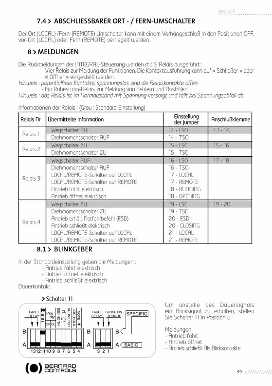
59
Deutsch
7.4 ABSCHLIESSBARER ORT - / FERN-UMSCHALTER
Der Ort (LOCAL) /Fern-(REMOTE) Umschalter kann mit einem Vorhängeschloß in den Positionen OFF, vor-Ort (LOCAL) oder Fern (REMOTE) verriegelt werden.
8 MELDUNGEN
Die Rückmeldungen der INTEGRAL-Steuerung werden mit 5 Relais ausgeführt : - Vier Relais zur Meldung der Funktionen. Die Kontaktausführung kann auf « Schließer » oder
« Öffner » eingestellt werden.Hinweis : potentialfreie Kontakte, spannungslos sind die Relaiskontakte offen. - Ein Ruhestrom-Relais zur Meldung von Fehlern und Ausfällen.Hinweis : das Relais ist im Normalzstand mit Spannung versorgt und fällt bei Spannungsabfall ab.
Informationen der Relais : (Grau : Standard-Einstellung)
8.1 BLINKGEBER
In der Standardeinstellung geben die Meldungen : - Antrieb fährt elektrisch - Antrieb öffnet elektrisch - Antrieb schließt elektrischDauerkontakt
Schalter 11Um anstelle des Dauersignals ein Blinksignal zu erhalten, stellen Sie Schalter 11 in Position B.
Meldungen- Antrieb fährt- Antrieb öffnet- Antrieb schließt Als Blinkkontakte
Relais Nr Übermittelte Information Einstellung der jumper Anschlußklemme
Relais 1Wegschalter AUFDrehmomentschalter AUF
14 - LSO14 - TSO
13 - 14
Relais 2Wegschalter ZUDrehmomentschalter ZU
15 - LSC15 - TSC
15 - 16
Relais 3
Wegschalter AUFDrehmomentschalter AUFLOCAL/REMOTE-Schalter auf LOCALLOCAL/REMOTE-Schalter auf REMOTEAntrieb fährt elektrischAntrieb öffnet elektrisch
16 - LSO16 - TSO17 - LOCAL17 - REMOTE18 - RUNNING18 - OPENING
17 - 18
Relais 4
Wegschalter ZUDrehmomentschalter ZUAntrieb erhält Notfahrbefehl (ESD)Antrieb schließt elektrischLOCAL/REMOTE-Schalter auf LOCALLOCAL/REMOTE-Schalter auf REMOTE
19 - LSC19 - TSC20 - ESD20 - CLOSING21 - LOCAL21 - REMOTE
19 - 20

60
8.2 MELDUNG RELAIS 1
In der Standardeinstellung meldet Relais 1 « Wegschalter AUF ». Der Jumper auf Sockel 14 steht in Position LSO (LIMIT SWITCH OPEN – Wegschalter offen).
Jumper Sockel 14Um das Ansprechen des Drehmomentschalters durch Relais 1 anzuzeigen, bringen Sie Jumper auf Sockel 14 in Position TSO (TORQUE SWITCH OPEN – Drehmomentschalter öffnen).In der Standardausführung, ist der Kontakt des Relais 1 als Schließer ausgeführt. Der Jumper auf Sockel 22 steht in Position
Jumper Sockel 22
Um den Kontakt in Relais 1 als Öffner zu benutzen, bringen Se den Jumper auf Sockel 22 in die Position
- Einstellungvon Relais 1 : Jumper Sockel 14 und 22
8.3 MELDING RELAIS 2
In der Standardeinstellung meldet Relais 2 « Wegschalter ZU ». Jumper auf Sockel 15 steht in Position LSC (Limit Switch Close).
Jumper Sockel 15Durch Ändern des Jumpers auf Sockel 15 in Position TSC (Torque Switch Close) meldet Relais 2 « Drehmomentschalter schließen ».In der Standardeinstellung ist der Kontaktvon Relais 2 als Schließer ausgeführt. Der Jumper aufSockel 23 steht in Position
Jumper Sockel 23
Bringen Sie den Jumper auf Sockel 23 in Position , um den Kontakt von Relais 2 als Öffner zu nutzen..
- Einstellung zu Relais 2 : Jumper auf Sockel 15 und 23
8.4 MELDUNG RELAIS 3
In der Standardeinstellung meldet Relais 3 « Wegschalter AUF ». Der Jumper auf Sockel 16 befindet sich in Position LSO (Limit Switch Open).
Jumper Sockel 16, 17 and 18
Achtung: Es existiert nur ein Jumper für die drei Steckplätze Nummer 16, 17 and 18.
- Bringen Sie den Jumper auf Sockel 16 in Position TSO (Torque Switch Open), damit das Relais 3 « Drehmomentschalter öffnen » anzeigt.
- Bringen Sie den Jumper auf Sockel 17 in Position REMOTE, damit das Relais 3 meldet « Local/Remote in Position REMOTE (Fernbetrieb) ».
- Bringen Sie den Jumper auf Sockel 17 in Position LOCAL, damit das Relais 3 meldet « Local/Re-mote in Position LOCAL (vor-Ort-Betrieb) ».
- Bringen Sie den Jumper auf Sockel 18 in Position OPENING, damit Relais 3 meldet « Antrieb öffnet ». - Bringen Sie den Jumper auf Sockel 18 in Position RUNNING, damit Relais 3 meldet « Antrieb läuft ».

61
Deutsch
In der Standardeinstellung ist Relais 3 als Schließer ausgeführt. Der Jumper auf Sockel 24 stehtin Position
Jumper Sockel 24
Bringen Sie den Jumper auf Sockel 24 in Position , um das Relais als Öffner zu benutzen.
- Einstellungen an Relais 3 : Jumper Sockel 16, 17, 18 und 24- Nur 1 Jumper für Sockel 16, 17 und 18
8.5 MELDUNG RELAIS 4
In der Standardeinstellung meldet Relais 4 « Wegschalter ZU ». Der Jumper auf Sockel 19 steht in Position LSC (Limit Switch Close / Wegschalter zu).
Jumper Sockel 19, 20 und 211Achtung: Es existiert nur ein Jumper für die drei Steckplätze Nummer 19, 20 and 21. - Bringen Sie den Jumper auf Sockel 19 in Position TSC (Torque Switch Close/Drehmoments-
chalter schließen), damit Relais 4 meldet «Drehmomentschalter schließen». - Bringen Sie den Jumper auf Sockel 20 in Position CLOSING, damit das Relais 4 anzeigt
« Antrieb läuft ZU ». - Bringen Sie den Jumper auf Sockel 20 in Position ESD (Emergency Shut Down), damit das
Relais 4 anzeigt « ESD – Befehl erhalten » - Bringen Sie den Jumper auf Sockel 21 in Position REMOTE, damit das Relais 4 anzeigt
« LOCAL/REMOTE-Schalter in Position REMOTE (Fernbetrieb) ». - Bringen Sie den Jumper auf Sockel 21 in Position LOCAL, damit das Relais 4 anzeigt
« LOCAL/REMOTE-Schalter in Position LOCAL (vor-Ort-Betrieb).
In der Standardeinstellung wirkt der Kontakt von Relais 4 als Schließer. Der Jumper auf Sockel 26 steht in Position
Jumper Sockel 26
Bringen Sie den Jumper auf Sockel 26 in Position , damit Relaiskontakt 4 als öffner wirkt.
- Einstellung Relais 4 : Jumper-Sockel 19, 20, 21 und 26- Nur 1 Jumper für Sockel 19, 20 und 21
8.6 ALARMRELAIS
Das Alarmrelais signalisiert, daß der Antrieb nicht verfügbar ist oder eine unnormale Funktion ausführt. Das Alarmrelais steht im Normalfall unter Spannung und im Falle eines Fehler wird es spannungsfrei (Ruhestromprinzip). Das Relais wird durch folgende Effekte spannungsfrei : - Ausfall der Stromversorgung, der Fernsteuerspannung oder einer Sicherung - Ausfall eine Phase (bei Drehstromanschluß) - Auslösen des Temperaturwächters im Motor - Ausfall des Eingangssignals 4-20 mA (mit Zubehör-Positioner)* - LOCAL/REMOTE –Wahlschalter in Position LOCAL oder OFF**
* Bei der Version ohne Positioner ist Schalter 2 ohne Funktion.** Bei Zustand « Ortssteuerstelle blockiert/verriegelt » wird der Schalter in Position LOCAL nicht als Fehler angezeigt, weil der Antrieb weiterhin per Fernansteuerung funktionniert. Der Anwender kann die Bedingungen, in denen das Relais spannungslos wird, modifizieren.
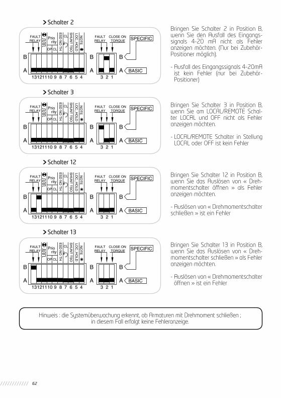
62
Schalter 2Bringen Sie Schalter 2 in Position B, wenn Sie den Ausfall des Eingangs-signals 4-20 mA nicht als Fehler anzeigen möchten. (Nur bei Zubehör- Positioner möglich).
- Ausfall des Eingangssignals 4-20mA ist kein Fehler (nur bei Zubehör- Positioner)
Schalter 3
Bringen Sie Schalter 3 in Position B, wenn Sie am LOCAL/REMOTE Schal-ter LOCAL und OFF nicht als Fehler anzeigen möchten.
- LOCAL/REMOTE Schalter in Stellung LOCAL oder OFF ist kein Fehler
Schalter 12
Bringen Sie Schalter 12 in Position B, wenn Sie das Auslösen von « Dreh-momentschalter öffnen » als Fehler anzeigen möchten.
- Auslösen von « Drehmomentschalterschließen » ist ein Fehler
Schalter 13
Bringen Sie Schalter 13 in Position B, wenn Sie das Auslösen von « Dreh-momentschalter schließen » als Fehler anzeigen möchten.
- Auslösen von « Drehmomentschalter öffnen » ist ein Fehler
Hinweis : die Systemüberwachung erkennt, ob Armaturen mit Drehmoment schließen ; in diesem Fall erfolgt keine Fehleranzeige.

63
Deutsch
9 SICHERUNGEN
Zugänglichkeit : - Schalten Sie die Spannungsversorgung des Antriebs ab. - Entfernen Deckel mit den lokalen Steuerschaltern. - Achten Sie auf das Kabel der Steuerschalter innerhalb des Deckels. - Entfernen Sie den Sicherungsverschluss und ändern Sie nötigenfalls die Sicherungen.
Technische Daten der Sicherungen :FU1 : Transformator Primärsicherung 6,3 x 32mm - 0,5A - 500VFU2 : Transformator Sekundärsicherung 5 x 20mm - 0,5AFU3 : Transformator Sekundärsicherung 5 x 20mm - 0,05A
10 ZUBEHÖR-POSITIONER
Der optionale Positioner ist mit der Grundplatine CI12701 verbunden. Der Positioner ermöglicht es dem Antrieb, eine Position proportional zu einem Eingangssignal einzunehmen. Das Einstellboard (GAM-K) des L. BERNARD-Positioners erlaubt : - lokale Stellanweisungen zu geben, - den Antrieb an das Eingangs-Signal anzupassen, - die Reaktion des Antriebs für den Fall eines Ausbleibens des Eingangssignals einzustellen.
10.1 EINGANGSSIGNAL-EINSTELLUNG
Das Standard-Eingangssignal beträgt 4-20mA
10.1.1 Betrieb mit Eingangssignal 0-20mA
Schalter 4 und 8Stellen Sie Schalter 4 und 8 in Position B für den Betrieb mit einem 0-20mA-Signal. Das Ausgangssignal ist ebenfalls 0-20mA.
10.1.2 Betrieb mit Eingangssignal 0-10V
Schalter 4, 8, 9 and 10Stellen Sie die Schalter 4, 8, 9 und 10 in Position B für den Betrieb mit einem 0-10V-Signal. Das Ausgangssignal bleibt hierbei 0-20mA.
10.2 EINSTELLUNG DER ARBEITSWEISE (DREHRICHTUNG)
Die Standardeinstellung ist 4 mA = Armatur geschlossen, 20 mA = Armatur offen.
Schalter 3
Potentiometer AnschlußStellen Sie Schalter 3 in Position B und das Potentiometer von Stellung « POT STD » in Position « POT REV », um bei 4 mA Armatur AUF und bei 20 mA Armatur ZU einzustellen.

64
10.3 EINSTELLUNG DER ‘STAY PUT’-FUNKTION
Bei Verwendung des Eingangssignals 4-20 mA besteht die Möglichkeiten, eine Sicherheits-Position im Falle des Ausfalls des Eingangssignal (=0 mA) einzustellen.In der Standardeinstellung ist die Stay Put-Funktion aktiviert, d.h. bei Signalausfall bleibt der Antrieb in der zuletzt angefahrenen Position stehen.
Schalter 5, 6 and 8Schalter 5 in Position B : Antrieb/Armatur öffnet bei Ausfall des EingangssignalsSchalter 6 in Position B : Antrieb schlließt bei Ausfall des EingangssignalsSchalter 8 in Position B, um die « Stay Put »-Funktion abzuschalten
10.4 TOTBAND
Diese Einstellung erfolgt werkseitig, man kann sie jedoch mit dem Potentiometer « DEAD BAND » einstellen. Um das Totband zu vermindern drehen Sie das Poti gegen den Uhrzeigersinn.
10.5 PROBEBETRIEB VOR ORT
Es ist möglich, vor Ort (Positioner-Karte GAM-K) ein Eingangssignal von 4-20 mA zu simulieren, um die Funktion des Antriebes zu überprüfen. Bei Vorhandensein des Schalters LOCAL/OFF/REMOTE muß sich dieser in Stellung REMOTE befinden.
- AUTO : Funktion mit externem Signal- 0% : Internes Signal 0% (4 mA bei Standard)- MAN : Internes Signal einstellbar von 0 bis 100%- 100% : Internes Signal 100% (20 mA bei Standard)
Stellen Sie den Steuerschalter auf Position 0%, MAN oder 100%. In Gezeigter Stellung MAN läßt sich mit dem Potentiometer « MANUELL » ein Eingangssignal von 4-20 mA simulieren.
Einstellung der Arbeitsweise/Drehrichtung
Eingangssignal-Typ
Ouverture 4mA 20mA 0mA 20mA 0v 10V
Fermeture 4mA 20mA 0mA 20mA 0v 10V
ArmaturReaktion
Schließen imUhrzeigersinn
Schließen gegenden Uhrzeigersinn
Schließen imUhrzeigersinn
Schließen gegenden Uhrzeigersinn
Einstellung/Programmierung
Standard
KarteCI2701:Schalter7 auf B und
Potentiometerin Stellung“POT REV”
Karte GAMK :Schalter 3 in Stellung B und Potentiometer
in Stellung
Standard
Achtung : bei Eingangssignalen von 0-20 mA oder 0-10V kann die « Stay Put »-Funktion nichtausgeführt werden und muß inaktiviert werden. Bringen Sie dazu den Schalter 8 in Position B.
Achtung : ein zu großen Reduzieren des Totbandes führt zum « Schwingen » des Antriebs

65
Deutsch
10.6 0%-EINSTELLUNG
Falls vorhanden, muß sich der Schalter LOCAL/OFF/REMOTE in Position REMOTE befinden. Stellen Sie den Steuerschalter auf Position 0%, um dem Antrieb einen Zufahr-Befehl zu erteilen (4mA).
Fall 1 : Antrieb beginnt zuzufahren, stoppt aber vor Anfahren des Wegschalters « ZU ». Drehen Sie das Potentiometer im Antrieb so weit, bis der Antrieb an den Wegschalter « ZU /
CLOSED » heranfährt, LED an. Stellen Sie das Potentiometer ein wenig in Gegenrichtung, bis die rote LED erlischt.
Fall 2 : Antrieb beginnt zu schließen, stoppt beim Wegschalter « ZU/CLOSED », die Anzeige LED « CLOSE/SCHLIESSEN » verlöscht aber nicht..
Drehen Sie das Potentiometer des Antriebs vorsichtig so lange, bis die rote LED « CLOSE/ZU » erlischt.
10.7 100% EINSTELLUNG
Falls vorhanden, muß sich der Wahlschalter LOCAL/OFF/REMOTE in Stellung REMOTE befinden. Stellen Sie den Steuerschalter in Position 100%, damit der Antrieb einen Auffahrbefehl erhält (20mA).
Fall 1 : Antrieb beginnt zu öffnen und stoppt vor « Wegschalter OFFEN/OPEN ». AM-K-Elektronikkarte vorsichtig im Uhrzeigersinn bis der Wegschalter « OPEN » anspricht.
Drehen Sie das Potentiometer dann etwas gegen den Uhrzeigersinn, bis die grüne LED (OPEN) erlischt.
Fall 2 : Antrieb beginnt zu öffnen, stoppt bei Stellung « OPEN » des Wegschalters, die grüne LED verlöscht aber nicht.
Drehen Sie das Potentiometer « ADJ 100% » (Adjustment 100% = 100%- Einstellung) vorsichtig gegen den Uhrzeigersinn, bis die grüne LED erlischt.
10.8 SPLIT RANGE (GETEILTES SIGNAL)
Die Platine des Positioners kann auf SPLIT-RANGE (geteiltes Signal) eingestellt werden.
Split Range bedeutet die Teilung des Eingangs-Signals in 4-12 mA und 12-20 mA. Das übliche kunden-seitige Signal beträgt 4-20 mA. Ein erster Antrieb wird für den Betrieb mit 4-12 mA und ein zweiter für 12 bis 20 mA-Signale eingestellt. Jeder Antrieb erhält aber die volle Signalbreite von 4-20 mA. Der erste öffnet komplett zwischen 0 und 50% des Signals und der Zweite zwischen 50 und 100%.
Schalter 1 und 2Bringen Sie Schalter in Position B, damit der Antrieb mit dem Eingangssignal 12-20 mA arbeitet.Bringen Sie Schalter 2 in Position B, damit der Antrieb mit dem E4-12 mA arbeitet.

66
10.9 STELLUNGSABFRAGE MIT ELEKTRONISCHEM STELLUNGSRÜCKMELDER TAM 4-20MA
In der Standardeinstellung wird das Potentiometer des Antriebes zur Meldung der Armaturenposition benutzt.
Schalter 7Bringen Sie Schalter 7 in Position B, um den Antrieb auf Betrieb mit Stellungsrückmelder TAM 4-20 mA anstelle des Potentiometers einzustellen. Die Platine CI2701 kann die Versorgungsspannung zum Melder (TAM oder FSG) bereitstellen.
10.10 FERNANSTEUERUNG AUTO / EIN-AUS STEUERUNG
Der Positioner kann mit einem Fernsteuersignal (0) 4-20 mA / 0-10V oder mit ÖFFNEN / SCHLIESSEN / STOPP-Funktionen angesteuert werden. Der Eingang AUTO / ON-OFF auf den kundenseitigen Klemmen (Kl. 37) erlauben zwischen beiden Möglichkeiten hin- und herzuschalten. Siehe hierzu auch Kapitel 5, ab Seite 4, Fernsteuerung.
Hinweis : die Fernansteuerung-Signale « AUTO / ON-OFF CONTROL » und « LOCAL CONTROL INHIBITION » (Ortssteuerstelle blockiert) benutzen den gleichen Eingang auf der Klemmleiste. Bei Inbetriebnahme des Positioners wird der Eingang automatisch der Funktion « AUTO / ONOFF CONTROL » zugewiesen. Die Funktion « Ortssteuerstelleblockieren (Local Control Inhibition) » kann bei Betrieb mit Positioner nicht genutzt werden.
11 ZUBEHÖR : MELDELEUCHTEN
Als Zubehör zur Anzeige vor Ort sind 3 Meldebeleuchten an der Ortssteuerstelle des Steuerungs-gehäuses vorhanden : - Anzeigelampe für OFFEN - Anzeigelampe für GESCHLOSSEN - Anzeigelampe für ANTRIEBS-SPANNUNGSVERSORGUNG AN.
12 ZUBEHÖR : TAKTGEBER
Der Taktgeber ermöglicht eine Verringerung der Antriebsgeschwindigkeit. Zum Beispiel als Schutz gegen Druckschläge bei zu schneller Stellgeschwindigkeit.
Dieses Modul ist mit dem Eingang „P202TEMPO“ der Integral + Steuerung verbunden. Die eingehenden Steuersignale werden in Einschalt- und Pausenzeiten der Motorrelais aufgeteilt.
Die Einschalt- und Pausenzeiten sind separat einstellbar: T. ON: 0,5 sek. bis 10 sek. T. OFF: 3 sek. Bis 2 min.Die Stellgeschwindigkeit des Antriebs bzw. der Armatur kann auf diesem Weg sehr klein eingestellt werden.Die Stellgeschwindigkeit ist für die Richtungen öffnen und schließen getrennt einstellbar.

67
Deutsch
Weg- Zeit- Diagramm1/ zusätzlicher Wegschalter „AUF“.2/ zusätzlicher Wegschalter „AUF“.3/ langsam öffnen.4/ schnell öffnen.5/ schnell schließen6/ langsam schließen.7/ einstellen der Pausenzeiten.8/ einstellen der Einschaltzeiten.9/ einstellen der Einschaltzeiten.10/ einstellen der Pausenzeiten.11/ Verbindung zu den zusätzlichen Wegschaltern (falls vorhanden).12/ Verbindung zur INTEGRIERT + KARTE.
Open
Close Time
1 4 5
3
2 6

68
PROBLEM URSACHE BEHEBUNG
Keine Funktion Spannungsversorgung des Antriebs
Überprüfen Sie die Spannung (Klemmen L1, L2,L3 bei Drehstrom, oder 0,1 bei 1-Phasen Wechselstrom). Die Spannung ist auf dem Typenschild angegeben.
Ein Signal für Ortsteuerung blockieren liegt an.
Stellen Sie sicher, daß der Antrieb kein Signal Ortsteuerstelle blockieren empfängt. Wenn bei ausgeschaltetem Gerät der Verbindungsanschluß für Ortssteuerstelle blockieren an Klemme 37 entfernt wird, kann ein Funktionstest des Antriebs durchgeführt werden.
Ein Notfahrbefehl (ESD) liegt an und überlagert alle anderen Befehle.
Stellen Sie sicher, daß der Antrieb keinen Notfahrbefehl empfängt. Bei ausgeschalte-tem Gerät kann Jumper 27 vom INTEGRAL+ Board entfernt werden. Achten Sie unbedingt darauf, die Position zu notieren, damit er wieder an die richtige Stelle gesetzt werden kann. Bei entferntem Jumper ist die Notfahrfunktion (ESD) blockiert und ein Funktionstest des Antriebes kann durchgeführt werden. Stecken Sie danach den Jumper wieder an seine ursprüngliche Position.
Sicherung defekt Einstellung der Art der Spannungsversorgung
Sicherung überprüfen und ersetzen.Überprüfen Sie die Position von Jumper 100 auf dem INTEGRAL+-Board. Bei Drehstrom: Position T Bei Wechsel-oder Gleichspannung: M
Auslösen des Thermoschutzkontaktes im Motor.
Die TH -Anzeige im INTEGRAL+ Board signalisiert das Auslösen des Thermoschutzkontaktes. Der Antrieb ist nach Abkühlung des Motors wieder einsatzfähig.
Das auskuppelbare Handrad bleibt in Funktion (nur bei Versionen mit elektrischem Sicherheitskontakt)
Stellen Sie sicher, daß sich das Handrad in ausgekuppelter Position befindet.
Jumper (Brückenstecker)- Einstellung ist fehlerhaft oder Jumper fehlen.
Auf dem INTEGRAL+-Board müssen sich 11 Jumper befinden. Es darf nur ein Jumper auf Sockel 16-17-18 sein und nur einer auf 19-20-21.
13 WAS TUN WENN … MÖGLICHE FUNKTIONSFEHLER BEI DER INTEGRAL-PLUS VERSION

69
Deutsch
PROBLEME CAUSE REMEDE
Der Antrieb arbeitet im LOCAL (vor-Ort-Modus, aber nicht im Fernansteuer (REMOTE) Modbus
Ortsteuerschalter (LOCAL/REMOTE) steht auf LOCAL oder OFF. Kontaktfehler: keine Spannung zwischen Klemme 6 und 7.
Stellen Sie den LOCAL / REMOTE Schalter auf REMOTE.Stellen Sie sicher, daß auf der Klemmleiste zwischen Klemme 5 und 6 eine Brücke vorhanden ist. Überprüfen Sie die Sicherung FU3 am INTEGRAL+ Board.
Spannungskontrolle: falsche Eingangsspan-nung.
Prüfen Sie die Anschlüsse im Spannungskontroll- Modus:Spannung 10 bis 55V: Klemme 5Spannung 90 bis 250V: Klemme 4
Der Antrieb arbeitet im Fernansteuer modus, jedoch nicht im vor-Ort-Modus.
Ortssteuerschalter (LOCAL/REMOTE) steht auf REMOTE oder OFF.
Stellen Sie den LOCAL/REMOTE Schalter auf LOCAL.Stellen Sie sicher, daß der Antrieb keinen Befehl zum Blockieren des Ortssteuerschalters bekommt.
Ein Befehl Ortssteuerschalter blockieren/verriegeln liegt an.
Bei ausgeschaltetem Gerät kann an Klemme 11 der Anschlußdraht für den Befehl entfernt werden, um eine Funktionsprüfung am Antrieb durchzuführen.
Der Antrieb arbeitet nicht mit der korrekten Drehrichtung.
Einstellung falsch. Der Motor wurde neu ange-klemmt und dreht jetzt in die falsche Richtung (z.B. bei Motorwechsel).
Prüfen Sie die Einstellung der Drehrichtung. Schalter 7 auf dem INTEGRAL+ Board:Position A: Schließen im UhrzeigersinnPosition B: Schließen gegen den Uhr zeigersinnBei Motorwechsel müssen die Anschlußdrahtfarben beachtet werden! In Zweifels-fällen prüfen Sie vorher die Drehrichtung. Um die Drehrichtung umzukehren, tauschen Sie die Anschlüsse 2 und 3 an der Motor-Anschlußklemme.
Der Antrieb stoppt nicht bei Ansprechen des WegschaltersZU/CLOSED
Der Antrieb ist auf Drehmo-ment-Schließen eingestellt.
Prüfen Sie die SCHLIESSEN -Einstellung (Schalter 1 auf dem INTEGRAL+ Board).
Der Wegschalter ZU ist falsch eingestellt.
Stellen Sie den Wegschalter ZU ein. Der Wegschalter ZU muß ansprechen, selbst wenn der Antrieb auf Drehmomentschließung eingestellt ist.
Der Motor wurde neu ange-klemmt und dreht jetzt in die falsche Richtung (z.B. bei Motorwechsel).
Bei Motorwechsel müssen die Anschlußdrahtfarben beachtet werden! In Zweifels-fällen prüfen Sie vorher die Drehrichtung. Um die Drehrichtung umzukehren, tauschen Sie die Anschlüsse 2 und 3 an der Motor-Anschlußklemme.

70
PROBLEM URSACHE BEHEBUNG
Der Antrieb stoppt nicht bei Ansprechen des WegschaltersAUF/OPEN
Der Wegschalter AUF ist falsch eingestellt.
Stellen Sie den Wegschalter AUF ein. Der Wegschalter AUF muß ansprechen bei geöffneter Armatur.
Der Motor wurde neu ange-klemmt und dreht jetzt in die falsche Richtung (z.B. bei Motorwechsel).
Bei Motorwechsel müssen die Anschlußdrahtfarben beachtet werden! In Zweifels-fällen prüfen Sie vorher die Drehrichtung. Um die Drehrichtung umzukehren, tauschen Sie die Anschlüsse 2 und 3 an der Motor-Anschlußklemme.
Keine Anzeigen aktiv Der Antrieb ist ausgeschaltet
Anzeigen sind nur aktiv, wenn der Antrieb eingeschaltet ist.
Die Drehmoment- Schalter-Anzeige ist nicht aktiv
Einstellungen falsch Prüfen Sie, ob das entsprechende Anzeige-relais auf Drehmoment-Anzeige eingestellt ist. Der Jumper auf dem INTEGRAL+ Board ist eingestellt: TSO für Drehmomentschalter ÖFFNENTSC für Drehmomentschalter SCHLIESSEN .
Der Drehmoment-Schalter wurde manuell ausgelöst.
Die Elektronik speichert die Daten nur während der Funktion. Weiterhin speichert die Elektronik die Daten nur in Bezug zur Drehhrichtung.
Die Drehmoment- Schalter- Anzeige kehrt nicht mehr zur Grundeinstellung zurück, obwohl der Drehmoment-Schalter nicht mehr in Aktion Ist
Servomoteur hors tension Drehmoment-Schalter- Datenspeicherung
Die Drehmoment-Schalter-Daten werden elektronisch gespeichert. Um den Speicher zu löschen, muß ein entgegengesetzter Fahr-befehl erfolgen.

71
Deutsch
PROBLEM URSACHE BEHEBUNG
Keine Funktion Spannungsversorgung am Antrieb
Überprüfen Sie die Spannung (Klemmen 1, 2, 3 bei Drehstrom oder 0,1 bei 1-Phasen Wechselstrom). Die Spannung ist auf dem Typenschild angegeben.
Ein Notfahrbefehl (ESD) liegt an und überlagert alle anderen Befehle.
VStellen Sie sicher, daß der Antrieb kein Notfahrsignal empfängt. Bei ausgeschaltetem Gerät kann der Jumper von Sockel 27 auf dem INTEGRAL+-Board entfernt werden.Achten Sie unbedingt darauf, die Position zu notieren, damit er wieder an die richtige Stelle gesetzt werden kann. Bei entferntem Jumper ist die Notfahr-Funktion blockiert und ein Funktionstest des Antriebes kann durchge-führt werden. Stecken Sie danach den Jumper wieder an seine ursprüngliche Position.
Sicherung defekt Sicherung am INTEGRAL+-Board überprüfen und ggf. ersetzen.
Einstellung der Art der Spannungsversorgung
Überprüfen Sie die Position von Jumper 100 auf dem INTEGRAL+-Board.Bei Drehstrom: Position TBei Wechsel- oder Gleichspannung: M
Auslösen des Thermoschutzkontakte im Motor.
Die TH -Anzeige im INTEGRAL+ Board signalisiert das Auslösen des Thermoschutzkontaktes. Der Antrieb ist nach Ab-kühlung des Motors wieder einsatzfähig.
Das auskuppelbare Handrad bleibt in Funktion (nur bei Versionen mit elektrischem Sicherheitskontakt)
Stellen Sie sicher, daß sich das Handrad in ausgekuppelter Position befindet.
Jumper (Brückenstecker)-Einstellung ist fehlerhaft oder Jumper fehlen.
Auf dem INTEGRAL+-Board müssen sich 11 Jumper befinden. Es darf nur ein Jumper auf Sockel 16-17-18 sein und nur einer auf 19-20-21.
14 WAS TUN WENN … MÖGLICHE FUNKTIONSFEHLER BEI POSITIONERN POSIGAM-PLUS,
MODUGAM-PLUS
In Zweifelsfällen über die Funktion der Einheit, stellen Sie zuerst den LOCAL/REMOTE Wahlschalter auf LOCAL = vor-Ort-Steuerung und betätigen Sie die ÖFFNEN/SCHLIESSEN Funktionen.

72
PROBLEM URSACHE BEHEBUNG
Der Antrieb arbeitet im LOCAL (vor-Ort) ÖFFNEN/SCHLI ESSEN Modus, nicht jedoch mit dem Einheitssignal(0)4...20mA oder 0-10V.
Schalter LOCAL/REMOTE steht auf LOCAL oder OFF
Stellen Sie den LOCAL/REMOTE-Schalter in Position REMOTE, um den Positioner zu nutzen (selbst wenn der Positioner auf manuell eingestellt ist).
Ein automatischer AN/AUS- Befehl liegt an und blockiert den Positioner
Stellen Sie sicher, daß der Antrieb keinen AUTO/ONOFF-Befehl erhält.Trennen Sie den Fernansteueranschluß (an Klemme 11) wie zur Überprüfung gefordert.
Der Anschluß zwischen Positioner Board und INTEGRAL+ Board ist gestört.
Überprüfen Sie die Verbindung zwischen Positioner-Board (GAM-K) und INTEGRAL+-Board (CI2701).
Das Potentiometer für die Signalübertragung im Antrieb ist falsch eingestellt.
Drehen Sie das Potentiometer im Antrieb um ein Vierteldrehung und wiederholen Sie die Einstellungen wie in der Inbetriebnahme-Anleitung gefordert.
Eingangssignal falsch am Positioner Board (GAM-K):4-20 mA Signal: Schalter 4 steht auf A Schalter 9 steht auf A Schalter 10 steht auf A0-20 mA Signal: Schalter 4 steht auf B Schalter 5 steht auf B Schalter 9 steht auf A Schalter 10 steht auf A0-10 V Signal: Schalter 4 steht auf B Schalter 5 steht auf B Schalter 9 steht auf B Schalter 10 steht auf B
Der Antrieb arbeitet in LOCAL Einstellung,nicht mit Fernansteuerung(REMOTE).
Der Auto - 0% - 100% Schalter steht nicht auf Auto
Überprüfen SIe die Einstellung des Auto-0%-100% - Schalters auf dem Board des Positioners (GAM-K).
Signalfehler Überprüfen Sie mit einem in Reihe an Klemme 30 geschalteten Milliampereme-ter das Referenz-Signal.
Signalpolarität Stellen Sie sicher, daß der Plus (+) des Signals an Klemme 30 anliegt.

73
Deutsch
PROBLEM URSACHE BEHEBUNG
Der Antrieb folgt nicht dem vorgegebenen Eingangssignal
Potentiometer falsch herum angeschlossen
Überprüfen Sie die Potentiometer-Anschlüsse (auf GAM-K).Das Potentiometer sollte für POT STD (Standardposition) wie folgt eingestellt sein:• 4 mA (oder 0 mA oder 0 V entsprechend zum Signal) = geschlossen und Schließen im Uhrzeigersinn.• 4 mA (oder 0 mA oder 0 V entsprechend zum Signal) = offen und Öffnen gegen den Uhrzeigersinn.Das Potentiometer sollte für POT REV (umgekehrte Position) wie folgt eingestellt sein:• 4 mA (oder 0 mA oder 0 V entsprechend zum Signal) = geschlossen und Schließen gegen den Uhrzeigersinn.• 4 mA (oder 0 mA oder 0 V entsprechend zum Signal) = offen und Schließen im Uhr-zeigersinn.
Signal vertauscht oder Einstellung falsch
Überprüfen Sie die Signaleinstellung.Schalter 3 am Positionerboard (GAM-K):Position A: 4 mA = Armatur zuPosition B: 4 mA = Armatur auf
Drehrichtung vertauscht Überprüfen Sie die Signaleinstellung.Schalter 7 am INTEGRAL+ -Board (CI2701):Position A: Schließen im UhrzeigersinnPosition B: Öffnen gegen den Uhrzeigersinn
Das Potentiometer für die Signalübertragung ist falsch eingestellt.
Drehen Sie das Potentiometer am Antrieb um ein Vierteldrehung und wiederholen Sie die Einstellungen wie in der Inbetriebnahme-Anleitung gefordert.
Der Motor wurde neu angeklemmt und dreht jetzt in die falsche Richtung (z.B. bei Mo-torwechsel).
Bei Motorwechsel müssen die Anschlußkabelfarben beachtet werden! In Zweifelsfällen prüfen Sie vorher die Drehrichtung. Um die Drehrichtung umzukehren, tauschen Sie die Anschlüsse 2 und 3 an der Motor- Anschlußklemme.
Der Antrieb stoppt nicht bei Auslösen des Wegschalters STOPP .
Der Antrieb ist auf Drehmoment-Schließen eingestellt.
Überprüfen Sie die Einstellungen für Schliessen (Schalter 1 am INTEGRAL+ -Board.)
Der Wegschalter ZU ist falsch eingestellt.
Stellen Sie den Wegschalter ZU richtig ein. Der Wegschalter ZU muß auch dann ansprechen, wenn der Antrieb auf Dreh- moment-Schließen eingestellt ist.
Die Position 0% ist falsch eingestellt.
Stellen Sie das Potentiometer im Antrieb richtig ein.

74
PROBLEM URSACHE BEHEBUNG
Der Antrieb stoppt nicht bei Auslösen des Wegschalters STOPP .
Der Motor wurde neu angeklemmt und dreht jetzt in die falsche Richtung (z.B. bei Motorwechsel).
Bei Motorwechsel müssen die Anschlußkabelfarben beachtet werden! In Zweifels-fällen prüfen Sie vorher die Drehrichtung. Um die Drehrichtung umzukehren, tauschen Sie die Anschlüsse 2 und 3 an der Motor-Anschlußklemme.
Der Antrieb stoppt nicht bei Ansprechen des Wegschalters OFFEN/OPEN
Der Wegschalter OFFEN ist falsch eingestellt.
Stellen Sie den Wegschalter OFFEN ein.Er muß bei Position OFFEN der Armatur ansprechen.
Die Position 100% wurde falsch eingestellt.
Stellen Sie die 100% am Potentiometer auf dem Positionerboard (GAM-K) ein.
Der Motor wurde neu an-geklemmt und dreht jetzt in die falsche Richtung (z.B. bei Motorwechsel).
Bei Motorwechsel müssen die Anschlußkabelfarben beachtet werden! In Zwei-felsfällen prüfen Sie vorher die Drehrichtung. Um die Drehrichtung umzukehren, tauschen Sie die Anschlüsse 2 und 3 an der Motor-Anschlußklemme.
Keine Anzeigen aktiv Der Antrieb ist ausges-chaltet (OFF).
Anzeigen sind nur bei eingeschaltetem Antrieb verfügbar.
Die Anzeigen des Drehmoment-schalters sind inaktiv.
Einstellungen sind falsch Prüfen Sie, ob das entsprechende Anzeige-relais auf Drehmoment-Anzeige eingestellt ist. Der Jumper auf dem INTEGRAL+ Board ist eingestellt :TSO für Drehmomentschalter ÖFFNENTSC für Drehmomentschalter SCHLIESSEN .
Der Drehmomentschalter wurde manuell ausgelöst.
Die Elektronik speichert die Daten nur während der Funktion. Weiterhin speichert die Elektronik die Daten des Überlastschutzes nur in Bezug zur Drehrichtung.
Die Anzeige des Drehmomentschalters kehrt nach dessen Betätigung nicht zur Ausgangsanzeige zurück.
Das Grundsignal liegt nicht an. Bei Standardeinstellung meldet der Antrieb einen Fehler und verharrt in der momentanen Position.
Schicken Sie ein Test-Signal zum Eingang.
Der Wahlschalter steht auf LOCAL oder AUS/OFF . In der Standard-einstel-lung meldet der Antrieb einen Fehler.
Stellen Sie den Wahlschalter auf REMOTE

75
Deutsch
15 BENUTZEREINSTELLUNGEN (*)
(*) Kreis oder Hervorhebung der Optionen im Zusammenhang mit Ihren Systemeinstellungen.
INTEGRAL+ (CI2701)
Spri
nger
& S
chal
ter
1 A B
2 A B
3 A B
4 A B
5 A B
6 A B
7 A B
8 A B
9 A B
10 A B
11 A B
12 A B
13 A B
14 LSO TSO
15 LSC TSC
16/17/18 LSO TSO lokal fern laufen öffnen
19/20/21 LSC TSC ESD schließen lokal fern
22
23
24
25 50 200
26
27
28 close open
POSITIONER GAM-K
1 A B
2 A B
3 A B
4 A B
5 A B
6 A B
7 A B
8 A B
9 A B
10 A B

BERNARD CONTROLS4 rue d’Arsonval - CS 70091 - 95505 Gonesse Cedex - FranceTel: +33.1. 34.07.71.00 - Fax: +33.1.34.07.71.01E-mail: [email protected]: http://www.bernardcontrols.com
BC GROUP
BELGIUMBERNARD CONTROLS BENELUXBRUXELLESinquiry.belgium@[email protected]. +32 (0)2 343 41 22
CHINABERNARD CONTROLS [email protected]. +86 (0) 10 6789 2861
FRANCEBERNARD CONTROLS FRANCEGONESSE (PARIS)[email protected]. +33 1 34 07 71 00
GERMANYBERNARD CONTROLS [email protected]. +49 22 41 98 340
ITALYBERNARD CONTROLS [email protected]. +39 02 931 85 233
KOREABERNARD CONTROLS [email protected]. +82 2 553 69 57
MIDDLE-EASTBERNARD CONTROLS MIDDLE-EASTDUBAI - [email protected]. +971 4 880 0660
CHENNAI - [email protected]. +0091 9566204444
RUSSIABERNARD CONTROLS [email protected]. +7 499 251 06 54
SINGAPOREBERNARD CONTROLS [email protected]. +65 65 654 227
SPAINBERNARD CONTROLS [email protected]. +34 91 30 41 139
UNITED STATESBERNARD CONTROLS [email protected]. +1 281 578 66 66
Exhaustive list of agents and distributors on www.bernardcontrols.com