COMMERCIAL–IN-CONFIDENCE Submarine Cable System Functions & Repair.
36
COMMERCIAL–IN-CONFIDENCE COMMERCIAL–IN-CONFIDENCE Submarine Cable System Functions & Repair
-
Upload
mervin-ross -
Category
Documents
-
view
232 -
download
6
Transcript of COMMERCIAL–IN-CONFIDENCE Submarine Cable System Functions & Repair.

COMMERCIAL–IN-CONFIDENCECOMMERCIAL–IN-CONFIDENCE
Submarine Cable SystemFunctions & Repair

COMMERCIAL–IN-CONFIDENCE2
IP Cloud

COMMERCIAL–IN-CONFIDENCE3
World Submarine NW Map

COMMERCIAL–IN-CONFIDENCE4
DWDM
WDM (Wavelength Division Multiplexing), it uses different wavelengths on the same fibre & is totally protocol independent (SDH, ATM, Ethernet…)
It is known as Dense Wavelength Division Multiplex (DWDM) when the wavelengths are close (a few nm.)For a DWDM Transmission system, 40/80 or at present 160 or more wavelengths in Optical C-Band (1530nm to 1565nm wavelength spectrum) can be carried on one fibre.

COMMERCIAL–IN-CONFIDENCE5
Why DWDM
a) Overcome fiber exhaust / lack of fiber availability problems (better utilization of available fiber)
d) Cost effective transmission
e) No O-E-O conversion delays
f) Wave length leasing instead of Bandwidth leasing
b) Space and Power savings at intermediate stations
c) Easier capacity expansion

COMMERCIAL–IN-CONFIDENCE6
Evolution of Submarine Transmission Technology
SDH & DWDM combined
SDH and DWDM are complementary.
SDH provides:• flexibility• resilience in case of failure
DWDM provides:• very high bandwidth
So For higher bandwidth transmission over a longer distance on the International network across continents/countries, SDH & DWDM combinely evolves to Submarine Transmission network

COMMERCIAL–IN-CONFIDENCE7
Submarine Fiber Optic Network system
Fully integrated Undersea SystemUsing with -
CablesRepeatersBranching UnitsTerminal Equipment
SLTE, PFE, LME, NMS and DCN

COMMERCIAL–IN-CONFIDENCE
What makes a Submarine Cable Network
8
Cablestation
TerminalEquipment
Cable RepeaterPower FeedingEquipment
Branching unit
Network Management

COMMERCIAL–IN-CONFIDENCE9
Undersea Cables

COMMERCIAL–IN-CONFIDENCE10
Double Armoured Cable – For Deep & Rocky Seabed for double protection

COMMERCIAL–IN-CONFIDENCE11
Functions of Submarine Network

COMMERCIAL–IN-CONFIDENCE12
Functions & Terminologies

COMMERCIAL–IN-CONFIDENCE13
Submarine Wetplant & components
Wet plant comprises the following equipment/components:
Undersea Cable Land Cable Optical Fiber Cable joints Undersea Repeaters Gain equalizers Branching Units

COMMERCIAL–IN-CONFIDENCE14
Major Components of Submarine system
WTE+
TLA
LME
N Channels
PFEOGPP
TRPDR l 1
TRPDR l 2
TRPDR l 3STM-16/ STM-64Ÿ
ŸŸ
RL Cable
HV Power
BuildingGround
OceanGround
Ground
BeachJoint
SL-17Undersea
Cable
TRPDR l n
Cable Station
LTE #1
CTE
TRPDR Transponder
HV : High Voltage
LME : Line Monitoring Equipment
OGPP : Ocean Ground Protection Panel
PFE : Power Feed Equipment
RL : Rodent Lightning
TLA : Terminal Line Amplifier
WTE: Wavelength Termination Equipment
PLINB
HV ShieldUnderseaRepeater
Full Fiber DropBranching Unit
N Channels
TRPDR l 1
TRPDR l 2
TRPDR l 3
ŸŸŸ
TRPDR l n
LTE #2
ADM
STM-16/ STM-64
ADM
COTDR
NMS
SLTE & Wetplant
NMS

COMMERCIAL–IN-CONFIDENCE
Submarine Transmission Line Terminating Equipment
15
(optional) ILE
Line Monitoring Wavelengths(only for repeatered systems)Line Monitoring Wavelengths(only for repeatered systems)
10 Gbps (S-64.2) Interface
IP
OXC
ADMADM
ATM
WTEl1
l2
lN-1
lN
11
TRPDR
22
N-1N-1
NN
Note: Any module of the LTE may not be included depending on the specificrequirements of the system (distance, bit rate, SDH or SONET equipment, etc.)
Line Amp
Submarine Cable
OneFiber-Pair
N x 10Gbps

COMMERCIAL–IN-CONFIDENCE16
UnderSea Repeaters
Repeaters use state-of-the-art optical amplifier technology to achieve high performance and reliability in the transmission of multiple wavelength channel signals on multiple fiber pairs which normally use 980nm Pump for boosting up optical signal

COMMERCIAL–IN-CONFIDENCE17
Inside Repeater & different types
Amplifier Pair Chassis
Pump UnitControl Circuit
Erbium Amplifiers
Supervisory
Heat Transfer Plate
Locking Plate
Power Supply
1/2/3/4 up-to 8 Amplifier pairs per Repeater Low/High Gain Repeaters. Low noise & Wide BW Repeaters 980 nm Pumps used in Repeaters.

COMMERCIAL–IN-CONFIDENCE18
Gain Equalisers
Gain Equalizer function is needed for every 5-10 spans depending on the total length of system. It is required because of non-flat nature of EDFA amplifier to compensate the gain which results with wider range of wavelength for traffic.

COMMERCIAL–IN-CONFIDENCE19
Branching Unit
Branching units (BUs) are designed for use in systems having three or more landing sites. Optical signals are routed among the three cables that connect to the BUs.There are different types of BU’s. These BU can be controlled for electrical connections relay from the landing station SLTE equipment using commands on the same Optical channel.

COMMERCIAL–IN-CONFIDENCE20
Types of BU
1. Passive BU – The Electrical connections/branches can’t be switched or controlled from Station & it is electrically passive & doesn’t consume any electrical power. Also it is optically passive, means no Adding/Dropping of Wavelengths among three legs.
2. Power Switched BU – This type BU provides controllable electrical connections among the three cable legs, as well as to the sea-ground electrode built into the trunk leg cable termination. The electrical connectivity within the 34A-Type BU is controlled
on a powered system by means of an optical command signal & it will have a command receiver.
3. Power Switched OADM BU – It is similar to Power switched BU, but having optical add/drop functionality using a OADM inside the BU, which makes it optically & electrically controllable among three legs.
4. Non-power switched BU – It is similar to Passive BU, but having OADM functionality.

COMMERCIAL–IN-CONFIDENCE21
PFE
Under Sea Repeaters requires power for operation of Electronics circuit & the Power Feed Equipment (PFE) provides power to the these repeaters & Power switched BU.
These PFEs supply the power to undersea equipment in redundant arrangements called as dual end feed, for continuous operation even in the event of one PFE converter failure.
Different types of PFE from all SubSea suppliers available, depending on the power supply capability to feed the system, like 10Kv, 5Kv etc.

COMMERCIAL–IN-CONFIDENCE22
PFE – Submarine System powering overview
Example of a Trunk Point to Point Powering System
PSBU 1 PSBU 2
Example of a Normal Powering scenario for a Trunk and Branch Configuration
Current
Station A
PFE+
Station B
PFE-
Station A
PFE+
Station B
PFE-
Station C
PFE-
Station D
PFE-
Current
Virtual Ground

COMMERCIAL–IN-CONFIDENCE23
Fault Isolation & Repair in Wetplant
4 Detection and localization of Subsea faults
Two categories - Optical - Electrical
Electrical and optical faults can occur simultaneously (cable break) and separately (damaged or broken fibers with the power path intact, and insulation fault between the power path and the sea, commonly known as shunt fault, with fibers intact.

COMMERCIAL–IN-CONFIDENCE24
Types of SubSea Fault
Type 1 fault - Cable break for the cable being cut, with a break in the electrical insulation between seawater and the power-feeding conductor.
Type 2 fault - Open fault for the cable being cut, without breaking the electrical insulation between seawater and the power-feeding conductor. Type 3 fault - Shunt fault for a break in the electrical insulation between seawater and the power-feeding conductor, without this conductor itself been cut.
Type 4 fault - damage in the optical path without significant electrical alteration of the power-feeding conductor continuity and insulation.
Fiber
HV conductorOuter Cable
Outer Cable

COMMERCIAL–IN-CONFIDENCE25
Fault Localization techniques
Single-end DC measurements Type 1- Cable Break Type 3 – Shunt Fault Only accurate if you precisely remove contribution of repeaters and fault. Capacitive Method Type 2 - Open fault Conjugate Method (current-balance) Type 3 – Shunt Fault Accurate but also requires removal of contribution of the repeaters.
Optical Path (OTDR/COTDR) Type 4 - Optical Fault only OTDR only good to first repeater.
Electrical Path fault - Power Feed (output variation/ohms law) - PEFL (impedance mismatch) - DC Testing (IR, IC and CR) - Electroding (detection of a magnetic field due to applied tone)
COMMERCIAL–IN-CONFIDENCE26
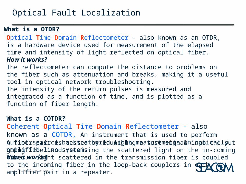
Optical Fault Localization
Optical Time Domain Reflectometer - also known as an OTDR, is a hardware device used for measurement of the elapsed time and intensity of light reflected on optical fiber.How it works?The reflectometer can compute the distance to problems on the fiber such as attenuation and breaks, making it a useful tool in optical network troubleshooting.The intensity of the return pulses is measured and integrated as a function of time, and is plotted as a function of fiber length.
What is a COTDR?Coherent Optical Time Domain Reflectometer - also known as a COTDR, An instrument that is used to perform out of service backscattered light measurements on optically amplified line systems.How it works?
What is a OTDR?
A fiber pair is tested by launching a test signal into the out going fiber and receiving the scattered light on the in-coming fiber. Light scattered in the transmission fiber is coupled to the incoming fiber in the loop-back couplers in each amplifier pair in a repeater.

COMMERCIAL–IN-CONFIDENCE
OTDR Vs COTDR
27
Light Pulse
OTDR
Repeater
HLLB
Repeater
HLLB
Repeater
HLLBBackscatter
Light Pulse
COTDR
Repeater
HLLB
Repeater
HLLB
Repeater
HLLB
Backscatter
OTDR can only measure up-to first repeater
OTDR can cross the repeaters & can measure till opposite end terminal

COMMERCIAL–IN-CONFIDENCE28
COTDR Measurement plot
COMMERCIAL–IN-CONFIDENCE
Electrical path Fault Localization
29
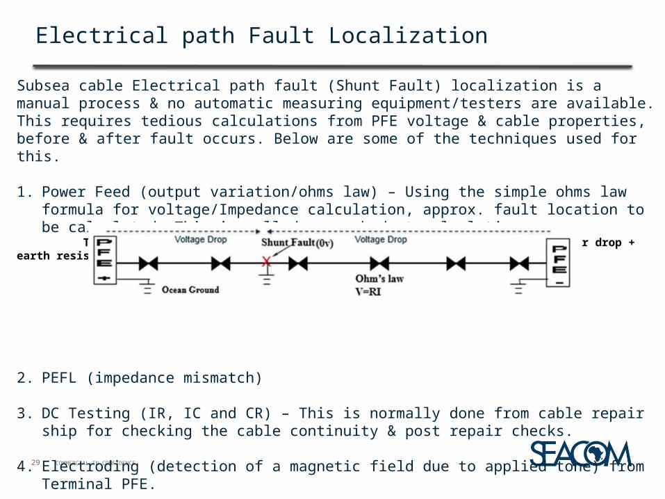
Subsea cable Electrical path fault (Shunt Fault) localization is a manual process & no automatic measuring equipment/testers are available. This requires tedious calculations from PFE voltage & cable properties, before & after fault occurs. Below are some of the techniques used for this.
1. Power Feed (output variation/ohms law) – Using the simple ohms law formula for voltage/Impedance calculation, approx. fault location to be calculated. This is called power budget calculation.
Total PFE voltage(Segment voltage) = Cable voltage drop + BU drop + Repeater drop + earth resistance
2. PEFL (impedance mismatch)
3. DC Testing (IR, IC and CR) – This is normally done from cable repair ship for checking the cable continuity & post repair checks.
4. Electroding (detection of a magnetic field due to applied tone) from Terminal PFE.

COMMERCIAL–IN-CONFIDENCE
Electroding
XElectroding Signal Low frequency A.C tone 4Hz to 50Hz
Fault Detected at Tone leakage point
Electroding is used for different purpose.1. To identify the exact location of fault in a suspected span,
either shunt or cable break from ship.2. To identify & pickup the exact cable system, out of many
cables laid on Seabed, during a repair activity from ship.
Electroding technique is sending low-frequency AC tone from Terminal PFE, using the capabilities of the PFE coupled & with special detection equipmenthaving low-current dc and low-frequency resistance and capacitance measurements which can be used in repair ship to find out the exact fault.

COMMERCIAL–IN-CONFIDENCE31
Subsea Cable repair
•The damaged Under Sea part of cable is repaired by specially equipped cable ships•A number of Cable ships are strategically located in different regions•Damaged portion of the cable will be lifted and removed by the cable ship and join again with a new piece of cable•The operation will take usually 10-15 days depending upon the distance of cable fault, Nature of the fault, spare availability in the ship and weather conditions.
ASN Cable Repairing.exe

COMMERCIAL–IN-CONFIDENCE32
A Shunt Fault
Shunt Fault –Single end Feed, Service affecting
Shunt Fault –Dual end PFE Feed, Not Service affecting

COMMERCIAL–IN-CONFIDENCE33
Cable Joints
Cable joints connect similar types of cable on land and at sea during initial cable laying & during a repair operation.
Sea Cable Joints

COMMERCIAL–IN-CONFIDENCE
Sub Marine cable System visual tour
34
Sub Marine cable system Video

COMMERCIAL–IN-CONFIDENCE35
CABLES AROUND AFRICA
►►

COMMERCIAL–IN-CONFIDENCE
Thank You!