Commercial Refrigeration Equipment Servicing Part...
93
Technical Training Associates Presents Commercial Refrigeration Equipment Servicing Part 1 By Jim Johnson A Practical Approach To The Fundamentals Of Walk-Ins, Reach-In and, Display Cases: Restaurant, Convenience Store and Grocery Store Equipment
Transcript of Commercial Refrigeration Equipment Servicing Part...
Technical Training Associates Presents
Commercial Refrigeration
Equipment Servicing Part 1
By Jim Johnson
A Practical Approach To The Fundamentals Of Walk-Ins,
Reach-In and, Display Cases: Restaurant, Convenience Store
and Grocery Store Equipment

2
Commercial Refrigeration Equipment Servicing Part 1 By Jim Johnson
Copyright © 2007 Technical Training Associates
HC 70 Box 3172
Sahuarita, AZ 85629
(520) 625-6847
www.technicaltrainingassoc.com
All hard copy and digital copyrights reserved. Distribution of hard copy versions to the
public for sale, or digital copying of any and all information contained herein is
prohibited.

3
TABLE OF CONTENTS
Part One: Metering Devices, Piping, & Heat Exchangers In Commercial Refrigeration Systems Part Two: Checking Superheat & Adjusting TXV‟s Part Three: Total Superheat & Subcooling Part Four: Alternative Expansion Devices In Commercial Refrigeration Equipment Part Five: What To Do If You Have To Replace An Expansion Valve Part Six: Misunderstood Devices In Commercial Refrigeration Systems Part Seven: More Misunderstood Devices In Commercial Refrigeration Systems Part Eight: Still More Misunderstood Devices In Commercial Refrigeration Systems Part Nine: The Fundamentals Of Commercial Equipment Electrical Systems Part Ten: The Fundamentals Of Commercial Equipment Electrical Components

4
PART ONE METERING DEVICES, PIPING, AND HEAT EXCHANGERS IN COMMERCIAL REFRIGERATION SYSTEMS
Troubleshooting commercial refrigeration systems is like troubleshooting
anything else…..we need to know what the unit is supposed to be doing in the
first place so we‟ll recognize “wrong” when we see it, and we need to be able to
apply our knowledge of fundamentals that applies to any refrigeration system,
while at the same time considering necessary modifications to those fundamental
concepts. The reason, of course, for the modifications is to get the equipment to
operate as efficiently as possible. In commercial equipment, piping and proper
operation of the metering device is critical to the efficiency of the system.
In domestic refrigeration systems such as the ones home appliance
technicians are familiar with in refrigerators and freezers, for example, some
method making contact between the suction line and the capillary tube is
employed in order to get the refrigeration system to operate as efficiently as
possible. Either the capillary tube-type metering device and the suction line will
be soldered together, or the “cap tube” (to use some official refrigeration
technician jargon) will be routed inside the suction line, then back out again so it
can be connected to the evaporator. In either case, the reason behind this
process is to allow a fractional horsepower refrigeration system to operate as
efficiently as possible….the refrigerant entering the evaporator at just the right
temperature and any liquid refrigerant that may be in the suction line being boiled
off so the operation of the compressor won‟t be compromised.

5
And the same basic concept applies in commercial refrigeration systems
where metering devices other than capillary tubes are used. (See Figure One)
Part One, Figure One

6
While heat exchangers may not be made up of a section of a cap tube and
suction line soldered together, some method of allowing contact between the
liquid refrigerant and the vapor refrigerant (in closed loops, of course) will be
employed. In this particular case, the metering device of choice is the TEV,
Thermostatic Expansion Valve because the system we‟re showing here is what
we would classify as a large system that might be 10 tons in capacity or more. In
some situations, the heat exchanger isn‟t as mysterious as the one we‟re
showing in Figure One. Instead, it will be more obvious, such as one loop of
tubing actually wrapped around another tubing segment, as we‟re showing in
Figure Two.
Part One, Figure Two
In this illustration, we‟re proving in a different fashion the idea that the piping
in both a domestic and a commercial refrigeration system has to be
accomplished in the right way in order for the system (and the metering device)
to operate properly. In a capillary tube metering device, such as you‟ll find in
domestic refrigeration systems and in some commercial equipment such as a
reach-in refrigerator, there are three segments, or, as they‟re sometimes referred
to, phases, of the tube to consider.

7
1. Liquid Length Phase
2. Bubble Point Phase
3. Two Phase
When refrigerant leaves the condenser, entering the capillary tube in a liquid
state, this early phase of the metering device is referred to as the Liquid Phase or
Liquid Length. While there is a pressure drop at this point, the refrigerant in this
segment of the tube is still 100% liquid. As the refrigerant continues through the
tube, the friction of the smaller tube eventually creates enough pressure drop to
allow the refrigerant to reach what is known as saturation, and when that occurs,
it‟s known as Bubble Point. It‟s at this point that flash gas becomes a factor.
As the refrigerant continues on its trip through the capillary tube, the amount
of flash gas increases due to the continued drop in pressure. This increased
restriction of fluid flow results in a further temperature drop of the refrigerant, and
it enters the last segment of the capillary tube as more of a combination of liquid
and flash gas…known as the Two Phase segment of the tube. Upon leaving this
segment of the tube, the refrigerant will be at the correct temperature when
entering the evaporator, providing any necessary heat exchangers are piped and
operating properly, and if the suction line piping that allows free flow of refrigerant
into the compressor is accomplished correctly.
What this means from a troubleshooting perspective is that in the event a
capillary tube is replaced, it‟s critical that the correct size and length be used. If
the cap tube is too large, the flow of refrigerant to the evaporator will be

8
excessive. If the replacement cap tube is too small, liquid refrigerant will back up
into the condenser and the condensing pressure (high side) will start to increase.
In either case, the efficiency of the refrigeration system will be compromised, and
the sometimes “standard fix” of adding refrigerant any time a unit is not
performing correctly will do nothing to alleviate the problem. Also, if the piping of
the heat exchanger is compromised (kinked tubing, loss of thermal contact, or
loss of insulation of a heat exchanger assembly) there will also be a loss of
efficiency, sometimes as much as 20%. And, as in the case of an incorrectly
sized capillary tube, in either bore or length, no amount of “dumping in gas” will
get the unit operating properly.
Another important piping consideration relative to proper metering device
operation is in the case of the TEV and the various locations of the evaporator
relative to the compressor. In the interest of maintaining good thermal contact
between the TEV sensing bulb and the suction line, the bulb should be located
on a horizontal section of tubing and the tubing should be pitched slightly
downward from the evaporator. That‟s the basic stuff relative to the proper
operation of this metering device. However, when servicing commercial
refrigeration equipment, you may find a situation in which there is more than one
evaporator. This doesn‟t mean that the fundamentals of refrigeration change, just
that depending on whether the evaporator is above or below the compressor,
there are some other factors to consider. (See Figure Three)

9
Part One, Figure Three
In a situation in which the compressor is below the evaporator, and no system
pump down is used, a short trap and a vertical riser extending to the height of the
evaporator should be used to prevent refrigerant from draining into the
compressor during an off cycle. And, while it‟s tempting to use that convenient
loop of tubing for mounting the TEV sensing bulb, the proper method of bulb
attachment is still on a horizontal section of the tube close to the evaporator coil.
And in the event that the system has pump down and the return tubing to the
compressor simply drops directly down at a 90-degree angle as our illustration
shows, the bulb still needs to go on a horizontal section of the tubing.
This rule also applies if the compressor is located above the evaporator as
we‟re showing in Figure Four.

10
Part One, Figure Four
The purpose of the trap in these applications is to drain any liquid refrigerant
that may affect the operation of the TEV. You‟ll note that we‟re showing the trap
being constructed as short as possible to minimize the amount of oil that will be
in that segment of the piping at any given time. When this type of trap is
constructed of Street Ells, it will allow the segment to be as short as possible.
When standard 90-degree Ells are used, it often means that the trap will be
longer than it should be.
Still another situation in which the piping of a commercial refrigeration system
must be accomplished correctly to facilitate proper metering device operation is
in the case of multiple evaporators. (See Figure Five)

11
Part One, Figure Five
On multiple evaporators, what you want to look for is the suction line piping
arranged so the flow of refrigerant and oil from one evaporator won‟t affect the
feeler bulb operation of another evaporator. Often, in multiple evaporator
systems, the main suction line is positioned as we‟re showing it, with one
evaporator above and another one below. In these situations, an inverted trap at
the point where the lower evaporator is piped to the suction line will prevent the
migration of oil into the lower coil. Without this type of trap system, any oil
migration will cause the temperature of the lower evaporator suction line to
fluctuate. And, when this happens, the TEV will act as though it is hunting,
opening too far too quickly, then shutting down too far. The end result of this

12
process will, again, be a lower-than-normal efficiency of the refrigeration system
overall, which will in the end cause a box temperature that will be above normal,
even though the run cycles of the system seem quite long.
All of which boils down to the fact we mentioned at the beginning of this
segment….that piping needs to be accomplished correctly in order for any
metering device to operate properly, enabling the refrigeration system to
accomplish maximum heat transfer.
And now that we‟ve provided an overview on some of the fundamental things
relative to the specifics of commercial refrigeration equipment, we‟ll move on to
Part Two where we‟ll discuss the subject of TXV‟s (Thermostatic Expansion
Valves) and superheat.

13
PART TWO
CHECKING SUPERHEAT AND ADJUSTING TXV‟S
As we mentioned in Part One, we‟re going to move on to focusing on
commercial refrigeration systems and the fundamental things you need to
understand about superheat in this handbook segment. And by the way, we want
to say up front that when the term superheat is used, it always refers to a
refrigerant in a vapor state.
Specifically, the term superheat applies to any vapor that is above its
saturation temperature for a given pressure. What that means is that any heat
gained by a refrigerant after the change of state process has ceased in the
evaporator coil is superheat, because once a refrigerant has absorbed all the
heat it can through the process of changing in state from a liquid to a vapor, it is
saturated.
To gain a full understanding of superheat, consider that there are two
types ….evaporator superheat and total superheat (sometimes referred to as
compressor superheat.
EVAPORATOR SUPERHEAT
This type of superheat begins at the point we‟re showing in Figure One,
which is about 85% to 90% of the way through the evaporator, identified as the
100% saturated vapor point.

14
Part Two, Figure One

15
The simplest way to understand evaporator superheat measurements is to
say that if you could place a thermistor or thermocouple device at the point we‟re
identifying as the “End of evaporator” (which would be just a few inches away,
and closer to the compressor, from the sensing bulb of the thermostatic
expansion valve), we would be measuring the necessary temperature to
calculate superheat. And, if we could install a Schrader Valve at this same point,
we could, at the same time we‟re taking the temperature at the end of the
evaporator, use our gauges to measure a pressure. With these two
measurement accomplished, we could then effectively measure evaporator
superheat.
What‟s that you say? Installing a Schrader Valve at that point would be a
great deal of work just to be able to take simultaneous and true pressure and
temperature measurements? Well, we would agree with that. The idea of
recovering the refrigerant from the system just to install an access valve, then
evacuating and installing a new drier does seem like a lot of work just to be able
to make a superheat evaluation. But there‟s another way….take a look at Figure
Two.
This illustration looks a lot like the one we showed in Figure One, but there
is an important difference. Note the External Equalizer Line that runs from the
body of the thermostatic expansion valve to a point just downstream of the TXV
sensing bulb. If you‟re working on commercial refrigeration systems, it‟s a good
bet that rather than an externally equalized valve system like the one we showed
in Figure One, you‟ll find an externally equalized system being employed.

16

17
Consider the reasons an externally equalized valve would be required in a
commercial refrigeration system:
1. Anytime there are distributors feeding an evaporator.
2. When the pressure drop in an evaporator causes a temperature drop of two
degrees in coils that operate above 0-degrees F.
3. When the pressure drop in an evaporator causes a temperature drop of one
degree in coils that operate below 0-degrees F.
Or, to put it simply, the majority of commercial refrigeration systems, whether
it‟s a walk-in cooler (large coil, needing a distribution tube into several inlets) or
walk-in freezer (low-temp operation, large coil), or an ice machine (very low
temperature coil), distribution tubes are employed. For a view of a typical
multiple-distribution tube, externally equalized TXV installation, see Figure Three.
Part Two, Figure Three
What this drawing shows is that since the external equalizer line is connected
directly to the suction line just a couple of inches downstream from the point at

18
which the sensing bulb of the valve is located, there is, essentially, going to be a
connection directly to the refrigeration system at the very point we need to take a
gauge reading. That being the case, it would be much simpler to install a
Schrader Tee (maybe, as it often happens, one is already there…check the
system closely). Often, an external equalizer line is installed with a flare nut on
the equalizer tube and a male flare fitting installed on the suction line itself. If this
is the situation you find, then installing a tee (if it isn‟t already there) would
involve the simple process of initiating a pumpdown of the system. Once the
valve is installed and the external equalizer line is reconnected, allow the system
to run for 10 to 15 minutes so it will reach equilibrium. Then, you can read your
evaporator pressure at that point, while simultaneously taking a temperature
reading.
One other point to remember…if you have a system with a long history of
problems and you‟re planning on replacing the TXV, use an externally equalized
one even if the original is an internally equalized model. It‟s OK to replace an
internally equalized valve with an externally equalized one, though you can‟t
make the switch-out the other way around.
With all that said about being able to get a reading of both temperature
and pressure at the proper location, let‟s look at an example:
If you were working on an R-134a system on a walk-in cooler that showed
an evaporator outlet temperature of 30-degrees F and a low side pressure
reading of 20 PSIG, you could figure the superheat out by simply converting the
pressure you read to a temperature. When consulting a temperature/pressure

19
chart (such as the one shown at the end of this handbook segment), you would
find that a 20 PSIG reading would convert to a temperature of 23-degrees. Then,
all you have to do is the simple arithmetic of subtracting 23 from 30, and you will
have found that the evaporator temperature in our example was 7-degrees F.
This is an interesting example to consider when understanding the
evaporator superheat measurement process since one of the general rules of
thumb is that when a commercial refrigeration system is operating with an
evaporator coil temperature between 0 and 40-degrees F, the suggested
superheat setting is 6 to 8-degrees F.
When you put this factor together with the idea that you‟re trying to
achieve approximately 40-degrees F box temperature in a walk-in cooler, and
that means that the coil temperature would be approximately 15-degrees cooler
than that (25-degrees F)….and that converting 25-degrees to a pressure on an
R-134a T/P chart would bring you relatively close to that 30-degree example we
presented….well, you get the idea. This is a pretty common situation in walk-in
coolers.
What‟s that? Another question…? What about that process of taking a
pressure reading at the compressor, then factoring in a suction line pressure loss
to compensate before converting your pressure to a temperature? Well, that
process is fairly well-documented, and often used by technicians…but it should
be used only on air-conditioning systems, not on walk-in coolers and other
commercial refrigeration equipment.

20
By the way, what often happens if a technician doesn‟t understand the
idea of evaporator superheat (and they‟ve been told about the “magic numbers”
of 6 to 8-degrees superheat), and they take a pressure reading at the
compressor access valve instead of at the evaporator outlet? They get what is
referred to as a fictitious superheat value.
Due to pressure drop in the suction line, the same system we used as an
example could have a pressure reading of near 15 PSIG. Which, when converted
to a temperature would show up to be just about 15-degrees. And, with this
converted temperature used in the simple arithmetic process, the false superheat
calculation that would result would be 15-degrees…which would mean that the
technician, knowing the “magic numbers” of 6 to 8-degrees, might think that the
adjustment of the TXV needs to be throttled down so as to drop the superheat to
the correct level. Of course, the end result of all this is that the evaporator would
wind up being starved for refrigerant, the efficiency of the refrigeration system
would drop, and the compressor that depends on a cool suction gas would
operate at a higher-than-normal temperature. So, the system would experience
unnecessarily long run cycles and the life of the compressor would be shortened.
All because of a false superheat calculation.
The situation we just described sounds all too familiar….Unfortunately, it‟s
common to find this basic mistake being committed by a technician. But, it can be
prevented by providing a simple training overview on the subject of evaporator
superheat in a commercial refrigeration system. Coming up in Part Two, we‟ll
look at the concept of total superheat and also subcooling.

21
Part Two, Figure Four

22
PART THREE
TOTAL SUPERHEAT AND SUBCOOLING
In the Part Two, our focus was on the very specific subject of “Evaporator
Superheat” and what a technician needs to understand about it in order to
properly evaluate (troubleshoot) a commercial refrigeration system. Beyond the
issue of Evaporator Superheat is what‟s referred to as Total Superheat. A
technician troubleshooting a commercial refrigeration system such as that found
in a walk-in cooler or reach-in refrigerator needs to understand both types of
superheat. And along with that, there‟s the subject of subcooling. We‟ll cover
both subjects in this segment.
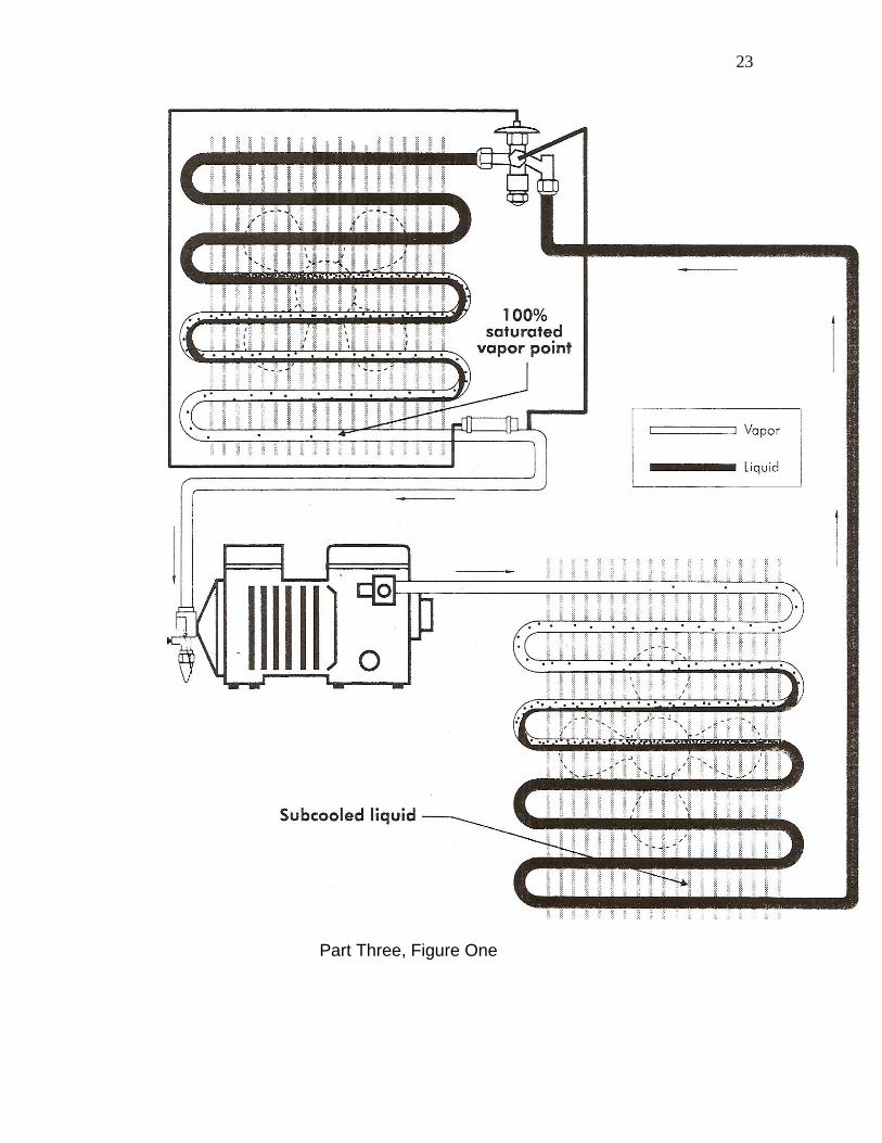
Total superheat, which is often referred to as compressor superheat, differs
from evaporator superheat in a very fundamental way. Total superheat is all the
superheat on the low pressure side of the refrigeration system, beginning at the
100% total saturation point, and not ending until the suction line connection on
the compressor. Evaporator superheat is measured only from the 100%
saturation point in the evaporator (which is usually about 90% of the way through
the coil) to the end of the evaporator, not including the suction line leading to the
compressor. One way to think about total superheat coming into play on a TXV
refrigeration system is in regard to the system operating on a light heat load,
meaning that the TXV will “lose control” over maintaining the proper amount of
evaporator superheat. This is something that could show up if you have a large
capacity walk-in freezer, for example, that has a small amount of food stored in it.
23
Part Three, Figure One

24
Whatever the situation, measuring total superheat in a commercial
refrigeration system can be accomplished. Then if necessary, adjusting the TXV
is a straightforward process. To make sure you have a complete understanding
of the total superheat concept, go back to Figure One and focus on the low
pressure side of the system only.
In the evaporator, you‟ll note the 100% saturation point shown very near the
end of the coil. If you trace down from this point to a point on the suction line that
would be, in reality about six inches away from the compressor, you‟re getting
the picture of total superheat. And, the process of measuring this superheat is
accomplished through two steps: One, is to take an accurate temperature
measurement at the point about six inches away from the compressor. The
reason you want to be careful about this point is that you don‟t want residual heat
from the compressor skewing the information about the actual temperature of the
suction line. The second step is to attach a gauge and get a pressure reading at
the low side access valve on the compressor. Once you‟ve converted the
pressure reading you got to a temperature by using a temperature/pressure
chart, all that‟s required is to do the simple math and subtract the calculated
temperature from the measured temperature to figure your superheat.
One point we want to stress about this process is that of getting an accurate
temperature reading of the suction line. Not only do you have to be careful about
selecting the test point, you also need to prevent the influence of ambient
temperatures on your reading. Holding a pocket thermometer up to the suction
line to get as much contact as possible and then wrapping some Armaflex
25
insulation around the tubing isn‟t going to provide the information you need. For a
small investment, you can get an accessory that connects to any good digital
meter capable of reading temperature, and clamps on tightly to the suction line.
With this type of sensing device you‟ll get an accurate temperature reading…and
without an accurate temperature reading, your superheat information will be
incorrect. Here are some of the reasons you may get a lower-than-normal total
superheat reading in a refrigeration system:
1. Dirty Coil. This is number one in the hit parade due to poor maintenance.
2. Low Air Flow Over The Coil. This one usually occurs due to an evaporator fan
replacement in which the improper motor was used. So do some checking on
the service history of the unit to find out if the “not cooling enough” complaint
goes back to the last service call in which the evaporator fan motor was
replaced.
3. Defrost Circuit Malfunction Causing Evaporator Icing: Something like a
defrost termination thermostat kicking the heating element or hot gas defrost
system off too soon could be the culprit here. Also, check to make sure that
the defrost time on the timer mechanism is properly set.
4. End Of The Refrigeration Cycle: If the unit is about to shut off, you may
experience a low superheat reading.
5. Low Refrigerant Charge: You‟ll note that we saved this one for last. The
reason? This is the conclusion that most “average” service organizations
jump to without even considering the first four causes we listed. The point

26
is…check the other things before assuming a low charge. Most of the
systems you check will be overcharged because many technicians don‟t
consider the other four possible causes of lower-than-normal superheat.
In most cases, manufacturers will prefer that their equipment operate with a
minimum of 20-Degrees of total superheat, and, in general, that‟s a good rule of
thumb to follow. Some manufacturers may even say that as superheat
somewhere between 20 and 30 degrees is OK, as long as the unit is achieving
its intended box temperature. However, if you measure a system that is
experiencing, let‟s say 27-degrees of total superheat, and the complaint is “not
cooling enough” you may have two tasks to accomplish. One would be to adjust
the TXV back so the superheat drops closer to the 20-degree mark, then, double-
check to make sure that the air flow over the coil is correct and that the system
isn‟t overcharged because somebody didn‟t consider the other factors we
mentioned in our list.
SUBCOOLING
Beyond the issue of superheat in a refrigeration system and determining
whether or not the charge is correct, there‟s subcooling to consider. Like
superheat, subcooling has two categories…condenser subcooling and total
subcooling. To understand either concept, consider where subcooling begins in a
refrigeration system. (See Figure Two)

27
Part Three, Figure Two

28
Focusing this time on the high pressure side of the system, trace the
discharge line from the compressor and note that the condition of the refrigerant
is a vapor. As it proceeds through the condenser, it begins to change in state to a
liquid, and there is a point at which the change is complete; where the refrigerant
is now totally a liquid. It‟s at this point at which subcooling begins. It‟s commonly
referred to as the 100% saturated liquid point in the condenser.
To measure subcooling from a fundamental perspective, you need to
follow the same kind of temperature and pressure measurement comparisons
that apply to superheat. By taking a pressure measurement on the discharge of
the compressor, then taking a temperature measurement at the end of the
condenser, you‟ll have the two pieces of information you need, one of which has
to be converted. Using T/P chart, convert the pressure reading from your gauge
to a temperature, then subtract the temperature you read from that to calculate
subcooling. Manufacturers often recommend that their equipment operate with a
condenser subcooling of 10 degrees.
Figure Three shows you the location to focus on when calculating
condenser subcooling in a system. With a device capable of providing an
accurate temperature reading, attach a sensor to the end of the condenser. In
our example, we‟re showing a reading of 95-degrees.

29
Part Three, Figure Three
30
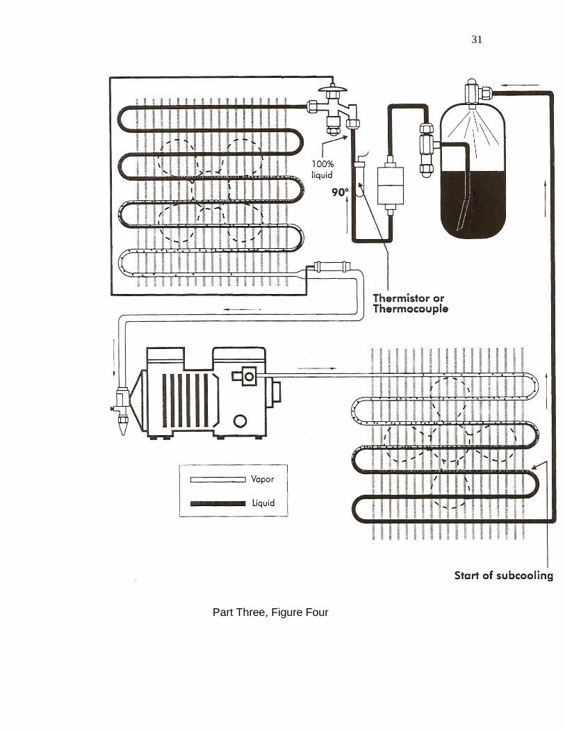
Another method of determining subcooling is known as total subcooling. In
this situation, your temperature measurement isn‟t accomplished at a point near
the end of the condenser coil, but instead a couple of inches away from the point
of entry into the TXV. Figure Four shows you an illustration of measuring
obtaining the temperature factor in a total subcooling measurement.
Here are some numbers you can use as an example of calculating
condenser subcooling:
Let‟s say that you‟re working on an R-22 system and you‟ve measured the
discharge pressure at 211 PSIG. Once you convert the pressure you read to a
temperature, your condenser subcooling calculation would look like this:
105 – 95 = 10 degrees
If you consult a T/P chart like the one shown at the end of this segment,
you‟ll note that at 211 PSIG, R-22 has a temperature of 105 degrees F.
On smaller commercial refrigeration systems, focusing on condenser
superheat is usually the best procedure to follow because when the total
subcooling process is used, it sometimes gets complicated due to having to
figure pressure drop into the equation. From an overall perspective, through,
when understanding condenser subcooling and the superheat process we
discussed in Parts 1 and 2, troubleshooting and servicing commercial
refrigeration systems can be accomplished in a straightforward and efficient
manner.
31
Part Three, Figure Four

32
Part Three, Figure Five

33
PART FOUR ALTERNATE EXPANSION DEVICES IN COMMERCIAL REFRIGERATION EQUIPMENT
There‟s no doubt that the competent commercial refrigeration service
technician needs a firm understanding of the standard TXV (Thermostatic
Expansion Valve) since, after all, it‟s the most commonly used metering device in
things like reach-in refrigerators, walk-in coolers and ice machines. Beyond the
standard TXV though, are other metering devices that are used in specific
applications. One example of this would be the AEV (Automatic Expansion
Valve). Another example of an alternative metering device in commercial
equipment…and one that is growing in popularity….is the EEV (Electronic
Expansion Valve). In this segment of Technical Update, we‟ll take a look at these
two types of valves, and discuss how they‟re similar, yet different from, the TEV.
We‟ll begin with an illustration of the Automatic Expansion Valve shown in
Figure One.
As you look at the details of this valve and its method of operation, one of
the first things you notice is that it doesn‟t use a sensing bulb like a TEV does.
(However, that doesn‟t mean that the AEV doesn‟t adjust to the heat load on the
coil….more on that in a moment.) Instead, the valve uses an adjustment spring
and screw assembly to regulate diaphragm pressure, and thereby regulate the
flow of refrigerant into the evaporator coil. In our example here, we‟re‟ showing
the operating conditions for a typical R-12 system (yes, you‟ll still find a lot of
older R-12 systems out there in this day and age) and the pressures you would

34
expect to find relative to the temperatures we‟ve listed. The situation we‟re
presenting here, we‟ll describe as a normal load.
Part Four, Figure One
One of the key factors to understand about the AEV and how it adjusts for
a heat load change is that it actually acts in reverse of a TEV. When the heat
load on the coil goes up the suction pressure in the system begins to rise. This
causes the AEV to throttle the refrigerant by closing enough to maintain the
proper suction pressure (its set point). The end result of this action by the valve is
that the coil is slightly starved for refrigerant. Figure Two shows you a slight
increase in heat load on our system.
35
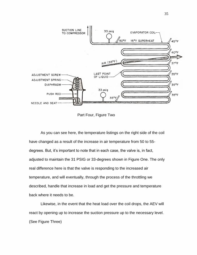
Part Four, Figure Two
As you can see here, the temperature listings on the right side of the coil
have changed as a result of the increase in air temperature from 50 to 55-
degrees. But, it‟s important to note that in each case, the valve is, in fact,
adjusted to maintain the 31 PSIG or 33-degrees shown in Figure One. The only
real difference here is that the valve is responding to the increased air
temperature, and will eventually, through the process of the throttling we
described, handle that increase in load and get the pressure and temperature
back where it needs to be.
Likewise, in the event that the heat load over the coil drops, the AEV will
react by opening up to increase the suction pressure up to the necessary level.
(See Figure Three)

36
Part Four, Figure Three
So while it‟s correct to say that the AEV operates in reverse of the TEV,
and that‟s a difference between the two valves because while the AEV does
modulate refrigerant flow but doesn‟t control superheat, it‟s also correct to say
that there are similarities. Both valves allow more or less refrigerant into the
evaporator in response to a load change, and they also both require a receiver to
store the excess refrigerant when it‟s not needed due to a low load. As far as
application of the AEV, it‟s best used in a situation where the load is somewhat
constant, such as a water cooler. The main advantage of an AEV in this type of
application is that it will prevent freezing while at the same time allowing the
water to be chilled as cold as possible.
37
And now, a bit about the EEV….
The electronic expansion valve is gaining popularity in many commercial
refrigeration applications because it is more accurate at controlling refrigerant
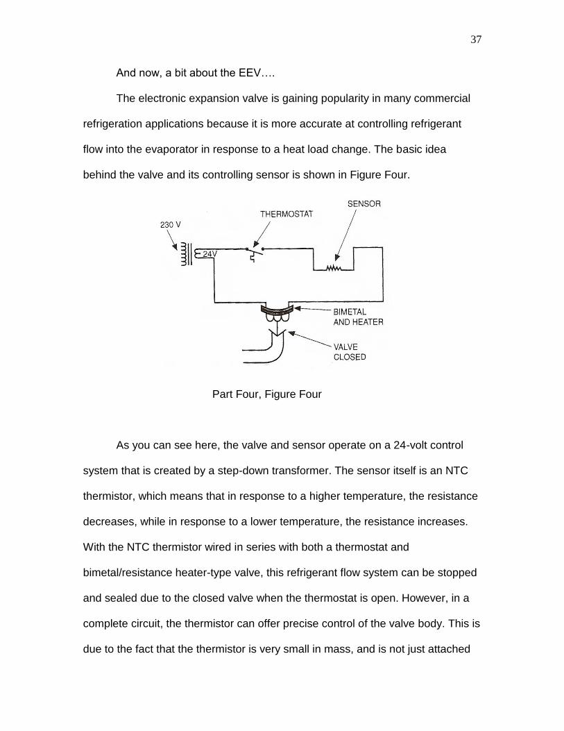
flow into the evaporator in response to a heat load change. The basic idea
behind the valve and its controlling sensor is shown in Figure Four.
Part Four, Figure Four
As you can see here, the valve and sensor operate on a 24-volt control
system that is created by a step-down transformer. The sensor itself is an NTC
thermistor, which means that in response to a higher temperature, the resistance
decreases, while in response to a lower temperature, the resistance increases.
With the NTC thermistor wired in series with both a thermostat and
bimetal/resistance heater-type valve, this refrigerant flow system can be stopped
and sealed due to the closed valve when the thermostat is open. However, in a
complete circuit, the thermistor can offer precise control of the valve body. This is
due to the fact that the thermistor is very small in mass, and is not just attached

38
to a tube, but is positioned down inside of it. Figure Five shows you a valve that
is responding to an increase in heat load.
Part Four, Figure Five
In this situation, you‟ll note that we‟re describing the process of vapor
refrigerant coming in direct contact with the thermistor. The result of a vapor
contact of the thermsitor is that its temperature goes up. And, in accordance with
the fundamental concept behind an NTC device, the resistance of the thermistor
goes down. In turn, this allows an increase in current flow through the 24-volt
circuit to the valve. The increased current flow causes the valve to open up more
and allow more refrigerant to enter the evaporator. This increase of refrigerant
flow, in the same way that the increase of refrigerant flow from a mechanical TEV
does, serves to handle the increase in load and keep the coil at its proper
operating temperature.
This is also accomplished in the event that the heat load drops. (See
Figure Six)
39
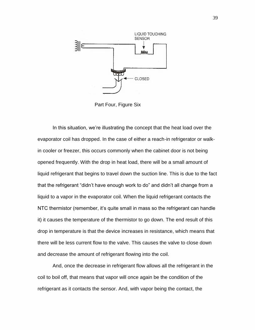
Part Four, Figure Six
In this situation, we‟re illustrating the concept that the heat load over the
evaporator coil has dropped. In the case of either a reach-in refrigerator or walk-
in cooler or freezer, this occurs commonly when the cabinet door is not being
opened frequently. With the drop in heat load, there will be a small amount of
liquid refrigerant that begins to travel down the suction line. This is due to the fact
that the refrigerant “didn‟t have enough work to do” and didn‟t all change from a
liquid to a vapor in the evaporator coil. When the liquid refrigerant contacts the
NTC thermistor (remember, it‟s quite small in mass so the refrigerant can handle
it) it causes the temperature of the thermistor to go down. The end result of this
drop in temperature is that the device increases in resistance, which means that
there will be less current flow to the valve. This causes the valve to close down
and decrease the amount of refrigerant flowing into the coil.
And, once the decrease in refrigerant flow allows all the refrigerant in the
coil to boil off, that means that vapor will once again be the condition of the
refrigerant as it contacts the sensor. And, with vapor being the contact, the

40
temperature of the sensor goes up again, causing the valve to open up and allow
more refrigerant flow into the evaporator. And, of course, what follows then, is
that there will soon be liquid refrigerant contacting the sensor and cooling it
down, which will cause it to increase in temperature and restrict the current flow
to the valve so it will again throttle down to restrict the flow of refrigerant into the
evaporator. The thing to remember about this modulation of refrigerant flow by
the valve is that there is not a wide swing in temperature. The operation of the
EEV system is constantly fine-tuning the adjustment of the refrigerant flow into
the coil. The end result, as we mentioned earlier, is a more precise control
system than that of a standard TEV. And, another advantage of the EEV over the
TEV is that there are no problems with improper positioning of a sensing tube,
nor is there a build-up of corrosion that will hinder the ability of the valve to get
the message regarding a load change in the evaporator.
All in all, the AEV and the EEV accomplish the same task as the standard
TEV that you‟re used to seeing on commercial refrigerant equipment, but they
get it done in a different way. Whatever the situation, a technician who has been
afforded the opportunity to study the simplicity of the AEV and the technology of
the EEV should have no problem troubleshooting and servicing a refrigeration
system that uses them.

41
PART FIVE REPLACING A THERMOSTATIC EXPANSION VALVE
In Parts 1,2, 3 and 4, our focus has been on the details regarding the
operation and adjustments of TEV‟s AEV‟s and EEV‟s. In this segment, we‟re
going to take things a short step beyond the idea of proper testing and
adjustment. We say a short step, because replacement of a sealed system
component that serves as a metering device is really just a short step beyond
understanding how it operates and how to set it properly. However, in the
commercial appliance arena, there have been countless instances of a poorly
accomplished sealed system component, which always leads to a nightmare
when it comes to correcting those situations. A quality service organization
should always be prepared to inherit a situation in which your only viable option
will be a major repair in regard to a metering device…meaning replacement of
the valve, either because an improper replacement was used, or the work wasn‟t
done properly.
As far as making sure you have the right valve for the job, if you can
determine that the original in still in place, then this part of the service task is
easy. If it‟s a Sporlan, Parker, or another manufacturer‟s valve that is Part #....
whatever, all you have to do is look it up in the manufacturer‟s product listings
and match your existing part number with either the same or replacement
number that they recommend. Also, even if you‟re changing from one
manufacturer to another due to an availability situation, you‟re often able to be

42
sure of an exact match because of cross-referencing material that is available to
you.
But, what if you‟re not sure whether or not the valve that‟s presently in
place is the original, or the numbers you have just don‟t match up? Well, it‟s
pretty simple. All you have do know is some basic facts about your equipment to
make the right choice.
You need to know….
1. The BTU capacity of the system.
2. The type of refrigerant used.
3. The evaporator temperature.
4. The pressure drop across the valve.
5. The liquid temperature entering the valve.
At first blush, the list above may give you pause because it looks like some of
those factors are things that are engineers are supposed to deal with, not
technicians. However, they‟re simple facts that can be understood with a simple
approach to research and understanding of the refrigeration system you‟re
servicing. In regard the #1, this is simply the tonnage rating of the system. Often
the best place to look for this information is on the condensing unit of the system.
The BTU/hr capacity of the unit will often be one of the pieces of information on
the equipment tag, along with the second factor you need to know….which
refrigerant is being used. We need to say that often, this information isn‟t going to
be easy to come by. You may need to spend a fair amount of time just accessing

43
the condensing unit so you can get a look at the equipment tag, and when you do
find it, you may wind up practically standing on your head with your Mag Lite,
trying to see past the dirt and grime to find the information you need. But, as
we‟ve said, these are the kinds of things that set a quality service organization
apart from the “average” service company.
Remembering the simple rule that there are 12,000 BTU‟s in one ton of
refrigeration capacity is your first step in identifying which thermostatic expansion
valve you‟ll need for a system. Manufacturers such as Sporlan or Parker provide
selection tables of their replacement valves that list their products by tonnage
ratings. In smaller systems such as a reach-in refrigerator, you may need a valve
that is rated only for 6,000 BTU‟s (One-half Ton) or even a 3,000 BTU (One-
quarter Ton) of capacity.
Another factor to keep in mind here about the refrigerant in the system is that
you may want to use this service opportunity to use a replacement refrigerant.
Since one of the things you would have to do to convert a system is to use a
different expansion valve anyway, consider the idea of making the conversion to
a refrigerant that will be a better fit for your customer. If it‟s a system that‟s using
R-12 for example, or if it‟s one of those blends that were the only thing available
at the time as a replacement, the equipment is a good candidate for a complete
changeover.
With the first two factors considered, we can move on to the third on our list,
which is understanding evaporator temperature. There are a couple of ways you
can approach this information. The first is to understand the simple rule that in a

44
walk-in or reach in unit, the actual coil temperature will be approximately 15-
degrees cooler than the design temperature of the box. So, as an example, if you
know that you‟re working with a walk-in cooler that is supposed to maintain 40-
degrees, then your actual coil temperature is going to be 25-degrees.
Another way to approach this is to recall some of the simple facts about low-
pressure controls in commercial refrigeration systems. Since it‟s common to find
this type of control used as a temperature control system, consulting the cut-in
and cut-out temperature settings can give you a fair amount of information about
the evaporator temperature. Figure One shows you some low-pressure control
settings for a variety of refrigerants.
Part Five, Figure One
With an understanding of cut-in and cut-out temperatures, you only need
to consult a temperature/pressure chart to accomplish the conversion you need.

45
Remember, a T/P chart can be used on two ways: First it can tell you what your
refrigerant pressure will be at a give temperature, and second, it will tell you what
your temperature will be when your refrigerant is at a certain pressure. So,
consult any available information regarding the low-pressure control and consult
a T/P chart to figure out what your coil temperature is likely to be.
Once you have this fundamental information in hand, you can begin your
search for the proper replacement valve in a manufacturer‟s catalog, which is
where you‟ll begin to find the other information necessary regarding pressure
drop and liquid temperatures entering the valve. Another point to understand
while consulting manufacturer‟s information is the correct power element. The
power element section of the TEV is the sensing bulb section, and manufacturers
will provide you with information relative to the kind of charge in the bulb…
whether it‟s a combination of liquid and vapor or liquid only. And, with the
information about the bulb charge and the five factors we listed previously
covered, you can begin the repair while keeping other things you need to
consider in mind.
There‟s the idea of positioning the valve to think about. In some cases, it
may require some piping changes in order to be sure that the installation won‟t
be harder than it should be due to the routing of tubing etc… And, you also need
to be sure that the type of valve equalization in a match. If the original design
called for a valve that is internally equalized, then an internally-equalized valve
should be used. If the original equipment was equipped with an externally
equalized system, then a valve that has an external equalizer port must be used.

46
By the way, you can tell if the person who was there ahead of you and
replaced a TEV but didn‟t do it right because they didn‟t understand the idea of
internal vs. external equalization systems. Sometimes, believe it or not, they‟ll
install an externally equalized valve in an internally equalized system and simply
cap off the external equalization port on the valve. Or, they‟ll ignore the externally
equalization requirement for a system by installing an internally equalized valve
and simply getting rid of the external equalized tube. In either case, their
approach is very wrong. So, when you‟re in the position of coming along behind a
service company that didn‟t do satisfactory work, look for signs of these incorrect
modifications. (For more information on the difference between internally and
externally TEV‟s review the information we covered earlier where we described
the fundamental operation of a TEV.)
To complete your installation, you may need to consider some
fundamental safety issues regarding brazing. It‟s a good idea to wrap the valve in
a heat-absorbing material while you solder the fitting connections. And, in
consideration of the installation of the sensing bulb, follow the general rule of
avoiding placing it on the bottom of the tube. In many cases, manufacturers
recommend that the best position for the sensing bulb on piping that is 7/8” or
larger is at the 4 or 8 O‟clock position. On smaller tubes, positioning the sensing
bulb on either side is the best rule to follow. And the last consideration for the
sensing bulb is to be sure that you use two clamps to make sure that there will be
good thermal contact between the bulb and tubing. Once you‟ve followed the

47
steps to make sure you‟re using the proper valve and have followed good
installation procedures, allowing the system to run for 15-minutes or so before
adjusting the superheat is a good rule of thumb to follow.

48
PART SIX
MISUNDERSTOOD DEVICES IN COMMERCIAL REFRIGERATION SYSTEMS
Now that we‟ve provided information on the fundamentals of commercial
refrigeration equipment operation, we‟ll move on to discussing some of the
system accessories that are used. No doubt, there a quite a few more devices to
understand in, say, the refrigeration system of a walk-in cooler as opposed to
that of a domestic refrigerator or room air conditioner. But, taking a proactive
approach to understanding system accessories can make the entire system
easier to understand. With that thought in mind, we‟ll discuss a few of those
refrigeration system accessories that can sometimes be a source of confusion for
technicians. We‟ll begin with a suction line accumulator such as the one we‟re
showing in Figure One.
Like any refrigeration system, the compressor in a commercial piece of
equipment is designed to pump vapor, not liquid. And in a perfect world, that‟s all
that would ever get into the suction line of the refrigeration system, causing the
compressor to be protected from liquid slugging. However, there are such things
as a dirty evaporator coil that would prevent the refrigerant from changing totally
from a liquid to a vapor, and when that happens we need to protect the
compressor. An accumulator is, in essence, nothing more than a storage tank on
the low-pressure side of the system. Domestic refrigerator evaporators have
them, and they appear as a segment of the evaporator. Room air conditioners
also have them, but they appear as a separate item in the piping of the suction

49
line. The room A/C accumulator appears more like those that you‟ll find in
commercial refrigeration systems, but there‟s still another step up.
Part Six, Figure One
As you can see in our illustration, in addition to the flow of refrigerant into
the accumulator and an outlet at the top showing vapor flow to the compressor,
there are a couple of additions to this particular example.
Note that there is what‟s referred to as a heater coil wrapped around the
body of the accumulator and that the condition of the refrigerant is this coil is
identified as “Hot Gas.” The place where the “Hot Gas” comes from, of course, is
50
from the condenser of the system. In commercial applications, manufacturers
often allow a pass of the discharge line of the compressor to be fastened to the
accumulator body. This heat exchanger (much like the heat exchanger that is
made up of the capillary tube fastened to the suction line in a domestic
refrigerator) ensures that any liquid refrigerant in the suction line will have some
„work to do‟ because of the heat being introduced, and completely change in
state to a vapor. Another feature found on commercial equipment accumulators
but not on domestic systems such as room A/C‟s is the oil return line located at
the bottom of the accumulator. Remember, in any refrigeration system there is a
certain amount of oil that travels with the refrigerant, and in commercial
equipment, this is going to be a higher volume of oil found traveling in a
refrigerator or freezer. Because of that, commercial refrigeration system suction
accumulators are often equipped with an oil return line that allows easy flow of oil
back into the crankcase of the compressor. Getting it directly into the crankcase
is much more efficient that trying to get oil to flow into the suction side of the
compressor, then be dealt with through the suction valves in a piston compressor
or the rotary vane of a rotary-type compressor.
And now on to another misunderstood accessory, the receiver.
In some of the smaller refrigeration systems such as those in reach-in
refrigerators or soda vending machines, the receiver will have an inlet at the top
and an outlet at the bottom. In larger units, however, the receiver can appear

51
differently because is uses a dip tube design, such as the one we‟re showing in
Figure Two.
Part Six, Figure Two
In this illustration, we‟re showing the receiver in a horizontal position,
which is a common method of positioning by some manufacturers. In some
cases, however, the receiver isn‟t horizontal, instead it‟s a vertical mount, such
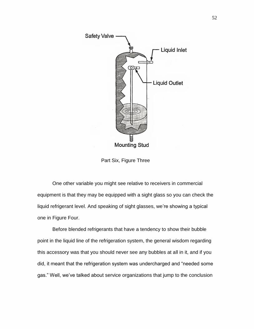
as we‟re showing in Figure Three.
Whatever the position, the purpose of the receiver is to act as a storage
tank on the high-pressure side of the system. In TXV systems, for example, we
have to put that extra refrigerant that we‟re not using in a low heat load situation
somewhere, and the somewhere is the receiver. Another use of the receiver on a
commercial refrigeration system is to allow an automatic system pumpdown or
for a manual pumpdown of refrigerant during a service procedure.
52
Part Six, Figure Three
One other variable you might see relative to receivers in commercial
equipment is that they may be equipped with a sight glass so you can check the
liquid refrigerant level. And speaking of sight glasses, we‟re showing a typical
one in Figure Four.
Before blended refrigerants that have a tendency to show their bubble
point in the liquid line of the refrigeration system, the general wisdom regarding
this accessory was that you should never see any bubbles at all in it, and if you
did, it meant that the refrigeration system was undercharged and “needed some
gas.” Well, we‟ve talked about service organizations that jump to the conclusion

53
that every time a walk-in, reach-in or ice machine isn‟t working right, the answer
is to “dump in some gas.” Not always true.
Part Six, Figure Four
In a situation in which there is a high heat load on a system, you‟ll likely
see bubbles in the sight glass on an initial start-up and probably even for several
minutes after that. Also, a restriction in the liquid line before the sight glass is
sure to create bubbles. And, since a sight glass is often used in conjunction with
a filter-drier on the liquid line (which can become restricted with contaminants) a
restricted system is sometimes mis-diagnosed as a system undercharge, when in
fact, the solution to the problem is to solve the restriction situation.
When a technician overcharges a system with a receiver to a certain
extent, the only indication is a slightly higher-than normal pressure on both the
high and low pressure sides of the system. In severe overcharge situations,

54
however, the entire receiver can be full of liquid. The bottom line on this situation
is that if a technician understands the concepts of superheat and subcooling we
discussed in previous segments, then they won‟t be mis-lead by bubbles in the
sight glass and jump to the conclusion that they have to add refrigerant.
Another situation in which bubbles can occur in the sight glass is in the
event of a sudden change in heat load in the middle of a cycle. Bringing in a
shipment of food products that need to be frozen or chilled and loading them into
a walk-in or display case is a good example of this situation. You also need to
consider the possibility that there has been a change in a head pressure control
system that could dump hot gas into the receiver to build head pressure up to a
point where it‟s supposed to be. One example of this would be a low ambient
control system on a condenser fan motor. If the condensing unit is located
outside in a cold temperature, the low ambient control would break the circuit to
the condenser fan motor to ensure that the high side pressure would stay up
where it‟s supposed to, maintaining a proper differential between the high and
low pressure sides of the system. (After all, if the high pressure and low-pressure
side of a refrigeration system are too close together, then the refrigeration
process won‟t be accomplished.) At the beginning of this head pressure rise due
to stopping the condenser fan motor, there may be bubbles in the sight glass.
And, of course another use for the sight glass is to check on the possibility
that there is moisture in the system. Manufacturers use a variety of colors to
determine if a system is wet or dry (green, yellow, etc…) so you need to check
the color code on the sight glass itself to determine whether or not there is

55
moisture in the system. This can be difficult in older systems since the colors
printed on the sight glass body tend to fade. In the event that you can‟t determine
whether or not there is moisture in the system, monitor the high side pressure
closely. If, without the introduction of any heat load changes, the high side
pressure tends to fluctuate, that would be an indicator of non-condensibles in a
system. And, if there are non-condensibles (air) in a system, that means that
there is also moisture present. This situation usually occurs due to improper
service procedures in which the technician doesn‟t take the time to purge the
hoses on their gauge set before adding refrigerant (which they likely didn‟t have
to add in the first place), and the end result is the introduction of non-
condensibles into the system along with the added refrigerant. In a situation like
this, your only quality service solution is to recover the refrigerant, install a new
filter-drier on the liquid line and also add a drier on the suction line, evacuate to a
proper level using a micron gauge and re-charge the system.

56
PART SEVEN MORE ON MISUNDERSTOOD DEVICES IN COMMERCIAL REFRIGERATION SYSTEMS
In Part Six, our focus was on a few of the common refrigeration system
accessories found in commercial equipment such as walk-in‟s reach-in‟s or
display cases. In this segment, we‟ll pick up where we left off by talking about
commercial equipment filter-driers.
It‟s more common to find a filter-drier on both the liquid line and suction
line in commercial systems. This is largely due to the fact that there are more
sealed system repairs done in the commercial arena….major repairs that are the
result of a compressor burnout….which is the reason the suction line filter-drier
shows up more often. As far as the basic construction of either one, Figure One
shows you what they look like on the inside.
Part Seven, Figure One

57
One thing you‟ll note about this illustration is that it shows an arrow that
points out the direction of flow through the drier assembly. This is a simple, yet
very important point to remember about any filter-drier. When the refrigerant
enters the assembly in the proper direction, it is allowed to free-flow through
before being forced through a more dense material at the outlet side of the drier.
If, however, the drier is installed backwards, the refrigerant hits the more dense
material first, and the result is a restriction of flow. Of course, if you restrict the
flow of refrigerant in any way, then provide an area for free flow, what you‟re
simulating is a metering device of some sort, then a kind-of evaporator. Which
means that a filter-drier that is installed backwards will be acting like a little
evaporator….cool to the touch, or maybe even frosting a bit.
(By the way, from a troubleshooting perspective, if a liquid line drier starts
to fill up with moisture and debris, it will also be cool to the touch because it is
restricting refrigerant flow, so keep that in mind too. The drier doesn‟t just have to
be installed backwards to show the “cool to the touch” restriction problem.)
And, now on to the suction line filter drier. In order for you to get an
understanding of how it compares to a liquid line filter-drier, we‟re showing both
of them in Figure Two.
The one on the left is the suction line drier, and you‟ll note when you look
closely that it has two service ports on it that allow you to connect your gauges.
Unfortunately, many service technicians see these service ports as nothing more
than a convenient place to connect their gauges so they can “dump in some gas”
while servicing the system. Well, that‟s not how an above-average service

58
organization looks upon these two connections on the suction line drier. They
know that the two ports are there so they can check for pressure drop across the
drier.
Part Seven, Figure Two
Here‟s the simple story on suction line driers…
Most often, a suction line filter-drier is installed on a system in the event of
a major repair, such as a compressor burnout. The reason for the addition of the
suction line drier is to filter the vapor refrigerant and catch an acid that may be
remaining, along with any solids. When the repair is first accomplished, the flow
through the drier should be without restriction. However, soon after the system
has operated for a while, the suction line drier, depending on how much acid and
other contaminants are in the system, can begin to clog up. How do you know?
By checking first on the inlet side of the drier for an operating pressure, then

59
check on the outlet side of the drier. If the pressure drop is less than 2 PSIG,
then the flow through the drier is OK. If, however, you get a pressure drop of
more than 2 PSIG, it‟s time to shut the system down, isolate the compressor,
recover all the refrigerant, and install a new set of filter driers.
The reasoning behind this is that the suction line drier is doing exactly
what you expect it to do – catch contaminants – and protect the new compressor.
If the pressure drop becomes too great, however, the refrigerant flow to the new
compressor will be compromised. Remember, in any vapor compression system
that uses a piston compressor, the compressor depends on a free flow of cool
refrigerant coming back down the suction line to help keep it cool. If that flow is
restricted, then the overall temperature and discharge temperature of the
compressor will be higher than normal, leading to a repeat compressor failure in
the equipment.
MUFFLERS….
A muffler is another accessory you‟ll see on commercial refrigeration
systems. If you‟re familiar with room A/C refrigeration system servicing, you‟ve
seen some version of one. Figure Three shows you the type commonly found on
commercial equipment.
Like the muffler you may have seen on room air conditioners, this type is
commonly found on the discharge line of the compressor, and it serves the same
purpose as the ones used on domestic systems…to reduce compressor noise.
However, on commercial equipment, there‟s one more caveat to keep in mind. In

60
some cases, if a system is large, it may have a muffler on the suction side of the
compressor as well. Sometimes mistaken for a suction line filter-drier without
access valves, it will be located fairly close to the compressor.
Part Seven, Figure Three
CRANKCASE HEATERS….
If you‟ve had any experience with servicing heat pump systems in residential or
light commercial applications, you‟ve likely seen a crankcase heater. It‟s an
accessory that is designed to keep a compressor crankcase warm in order to
prevent the migration of liquid refrigerant into the compressor on an off cycle. So,
what that means is that whenever the compressor is off, the crankcase heater
should be on. Figure Four shows you a situation in which a hermetic compressor
is fitted with an external crankcase heater.
Other situations in which you‟ll find an external crankcase heater (in both
hermetic and semi-hermetic compressors) is when the condensing unit of the
refrigeration system for the walk-in, ice machine, reach-in, or whatever, is located

61
in a cold environment such as just outside the kitchen. Another factor to keep in
mind about crankcase heaters is that they can be in the form of something other
than an external mount. In some cases (such as newer equipment), the
crankcase heater is an integral part of the compressor assembly.
Part Seven, Figure Four
In a well that is built into the compressor, the crankcase heater is inserted
and the wiring is the only thing showing exiting the compressor case. Which
means that if you‟re replacing a compressor with an external heater with one that
has an internal heater, all you have to do is hook up the appropriate wiring so the
new heater will operate in the same way the original one did.

62
And, when it comes to the wiring of a crankcase heater system, a
transformer is sometimes used to control its operation. Figure Five shows you a
simplified schematic of a crankcase heater control system.
Part Seven, Figure Five
In this segmented diagram, we‟re showing the compressor, along with an
accompanying outdoor fan motor, and we‟re controlling the operation of both
components with a set of normally open contact points. On the secondary side of
the step-down transformer symbol that makes up the body of the diagram itself,
we‟re showing the symbol for a contactor coil, which is controlled by a simple
switch. In most cases, this switch is a temperature-controlled device (like a
simple thermostat on a refrigerator) that calls for cooling.

63
On a call for cooling the switch is closed, providing a 24-volt circuit to the
contactor coil. When the coil is energized, the normally open contact points close
and compressor and condenser fan motor operate. But, the real story behind this
diagram is what happens when the temperature-operated switch in the system is
satisfied and the compressor and condenser fan motor turn off. Another set of
contact points (shown as C3 on the diagram) are identified as being normally
closed. And, you‟ll note that they are wired in series with a component identified
as CCH, which will be energized in an off-cycle, but then de-energized when the
compressor is operating.
This is the most common method of controlling the crankcase heater in a
commercial refrigeration system. However, in some situations in newer
equipment, there may be some reason the manufacturer has chosen to keep the
crankcase heater on when the compressor is running below a certain operating
temperature. In these cases, you‟ll likely find a thermistor and printed circuit
board type of control system that tells the crankcase heater when to be on and
off.

64
PART EIGHT STILL MORE MISUNDERSTOOD DEVICES IN COMMERCIAL REFRIGERATION SYSTEMS
In the last two segments, we discussed refrigeration system accumulators
and receivers, sight glasses, suction and liquid line filter-driers, and crankcase
heaters. Quite an extensive list of refrigeration system accessories, but there are
a few more to cover. In this segment, we‟ll discuss two types of valves that are
designed to control the refrigeration system pressures in the event of a
temperature changes. One of these is the EPR Valve, and the other is the CPR
Valve.
First, the Evaporator Pressure Regulator Valve….
The EPR valve is located on the suction line of the refrigeration system
and refrigerant flows into it from the evaporator, then on into the compressor. The
basic idea behind the operation of the EPR valve is to modulate the flow of
refrigerant, thereby maintaining the correct pressure in the evaporator. As you
know, temperatures affect refrigeration pressures, and if the temperature of a coil
goes too low, then the pressure of the system could also drop to a lower-than-
desired level. Figure One shows you an illustration of the EPR valve.
One of the applications of an EPR valve is a chilled water system, which
you won‟t see much of in restaurant equipment, but it helps to know this so you
can gain a full understanding of the operation of the device. In a chilled water
system, the critical factor is to prevent freeze-up, so a drop in coil temperature
below a certain level is a critical factor in the proper operation of the system. So,
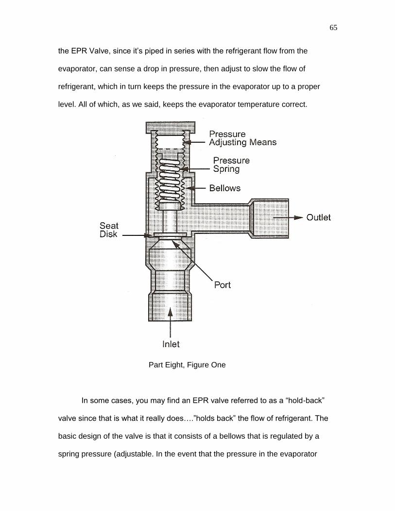
65
the EPR Valve, since it‟s piped in series with the refrigerant flow from the
evaporator, can sense a drop in pressure, then adjust to slow the flow of
refrigerant, which in turn keeps the pressure in the evaporator up to a proper
level. All of which, as we said, keeps the evaporator temperature correct.
Part Eight, Figure One
In some cases, you may find an EPR valve referred to as a “hold-back”
valve since that is what it really does….”holds back” the flow of refrigerant. The
basic design of the valve is that it consists of a bellows that is regulated by a
spring pressure (adjustable. In the event that the pressure in the evaporator

66
drops below what it‟s supposed to be, the spring pressure serves to control the
position of a seat disk, allowing either an increase of decrease in refrigerant flow.
This is often critical during a start-up of a refrigeration system. When there is a
high heat load on a start-up, the valve will remain wide open to allow maximum
refrigerant flow, then will modulate down slightly when necessary as the heat
load drops, and it will maintain the lower rate of flow until the system cycles off.
On a new cycle, the valve will again open wide to allow maximum flow.
If you find yourself working on a commercial refrigeration system that has
multiple evaporator coils, it‟s likely that you‟ll see EPR Valves in use. Figure Two
gives you an illustration of this application.
Let‟s say that you‟re dealing with a combination walk-in cooler/freezer
(sort of like a great big domestic refrigerator) that has to maintain a 40-degree
environment for things like vegetables, but in the freezer section, it needs to be
near zero for ice cream, etc… In that situation, you will often find two different
evaporator coils, one compressor, and one refrigerant being metered to both
coils in order to accomplish the refrigeration process. Common sense tells us
that in order to maintain these two very different cabinet temperatures, the coil
temperatures will be different, which would result in different coil temperatures.
And, this would be a problem for the refrigeration system overall because the
refrigerant would have a tendency to migrate to the lower-pressure coil, starving
the higher-pressure one. The solution, is to use an EPR Valve on each of the
coils in the system. (Our illustration shows four separate coils, but the same
concept applies to only two coils.)

67
Part Eight, Figure Two
As you can see, no matter what the varying pressures would be on the
individual coils, the suction line pressure leading back to the compressor is
always going to be maintained at 15 PSIG. This would be the case no matter
what the individual evaporator pressure would be, either above or below 15
PSIG.

68
When adjusting an EPR Valve, you need to know what the design
temperature of the cabinet is supposed to be, then apply the rule of thumb that
the actual coil temperature would be 15-degrees cooler than that number. For
example, if you had a coil in a cabinet that was supposed to be 40-degrees, then
the actual coil temperature would be 25-degrees. That would mean you could
use a temperature/pressure chart to plot what the refrigerant pressure was
supposed to be, put your gauges on the system while it was operating, then
adjust the spring pressure in the valve until the evaporator coil pressure was
correct. In most cases, this process is accomplished (and doesn‟t need to be
modified) at the time the system is installed. The problem, though, is that
sometimes, an average service organization doesn‟t know that they‟re supposed
to leave the EPR valve alone, and they try adjusting it to solve a complaint of “not
cooling enough”….when in reality the complaint is related to something simple
like a dirty condenser coil. So keep in mind that if you‟re following up on previous
unsatisfactory service by another company, look closely to see if the EPR valves
have been tampered with.
And, now, on to the CPR (Crankcase Pressure Regulator) Valve….
This valve, shown in Figure Three, looks very similar to the EPR valve.
Like an EPR Valve, it has a means to adjust a spring pressure and control the
flow of refrigerant through an opening, and it also has an inlet and an outlet. Look
closely, though at the indicators that show the path of refrigerant flow, and you
can see that when it‟s piped into a system, it can be identified as a CPR Valve.
While both valves are located on the suction line of the refrigeration system, their

69
inlet and outlet piping connections are reversed. And another tip-off that you‟re
looking at a CPR Valve rather than EPR Valve is that it‟s going to be located
closer to the compressor. In the situation in which an EPR Valve is used, it is
located much closer to the evaporator coil.
Part Eight, Figure Three
The function of a CPR Valve differs from an EPR in that its job is to protect
the compressor in the event of what‟s known as a hot pull-down. For example, if

70
a customer loads a reach-in with a lot of hot product, then there will be a severe
heat load on the system until that product is cooled down. In these situations, the
refrigerant returning to the compressor will be much more dense than under
normal operating conditions. And, since a refrigeration system compressor is a
constant volume pump, it won‟t know it is being overloaded, and the end result
could be a higher-than-normal current draw. Figure Four shows you an
illustration of a hot pulldown and what the CPR Valve is designed to do.
Part Eight, Figure Four

71
In this situation, we‟re showing a box that is experience a higher-than-
normal return air temperature, which is causing the low-side pressure to be
higher than it should be. For example, if this was a low-temperature display case
for frozen items, the return air temperature would likely be near 10-degrees,
which wouldn‟t have an effect on the pressure. However, with our high heat load,
the low side pressure is way up, and could cause the compressor to run for an
extended period of time at an amperage draw that could damage it. The answer
is the CPR Valve.
With the valve adjusted to throttle the higher pressure in the suction line,
the actual pressure of the refrigerant delivered to the compressor will be lower,
and the end result will be a normal current draw. Which means, of course, that in
order to adjust a CPR Valve, you‟re not going to be using your gauges this time,
only a clamp-on ammeter.
To begin either that adjustment process, or to check the operation of this
valve during a preventative maintenance procedure, determine what the current
draw of the compressor is supposed to be by checking the compressor tag or the
equipment manufacturer‟s equipment manual. Keep in mind that the compressor
should not operate at a current draw of more than 10% of its rated capacity
during a hot pull-down. For example, if the rated current draw of the compressor
was 20 amps, then you should not be exceeding 22 amps under a higher-than-
normal heat load in the box. If you experience a current draw of more than 10%,
adjust the valve until your ammeter shows a safe level.

72
Understanding this process and the operation of the CPR valve is an
important factor in advising your commercial customer about the value of
preventive maintenance. In the event that a CPR Valve is not adjusted properly,
the end result could be a compressor failure. Often, in situations in which your
customer tells you that they have had more than one compressor replacement in
a piece of equipment, check to make sure the CPR Valve is properly adjusted.

73
PART NINE THE FUNDAMENTALS OF COMMERCIAL REFRIGERATION EQUIPMENT ELECTRICAL SYSTEMS Up until now, our focus has been on the fundamentals of commercial
refrigeration systems and some of the commonly misunderstood devices
(accessories, actually) that are used to maximize the cooling capacity of things
such as walk-in coolers and freezers, reach-ins, or ice machines. And our point in
discussing those devices was that, since they are commonly misunderstood,
technicians often mis-diagnose problems with commercial refrigeration systems
and wind up replacing parts that don‟t need replacing. Well, the problem of mis-
diagnosis and unnecessary part replacement isn‟t limited to the refrigeration side
of commercial equipment servicing. Electrical mis-diagnosis is just as common,
and the underlying reason for it is the same as it is for refrigeration system
service error….a misunderstanding of how certain devices are supposed to work.
So, the question is, how does an above-average service organization
approach this problem? It‟s simple, really….they make sure the technicians faced
with this challenge have the tools they need to avoid those misdiagnoses. And
the place to begin providing those tools is with a simplified schematic diagram,
such as the one we‟re showing in Figure One.
In this illustration, we‟ve simplified a typical diagram for a walk-in cooler that
uses a remote condensing unit. In the process of simplifying it, we‟re showing
only the motors themselves with no special start devices or capacitors, and we‟re
showing a simplified control system that is electrical in nature.

74
Part Nine, Figure One
In many cases, pressure-sensing devices are used to control commercial
refrigeration systems, and we‟ll get to those…but first we‟ll focus on the
electrically-controlled system in order to make it as easy as possible for
technicians who are used to seeing thermostats on things like domestic
refrigerators and freezers. Starting at the top of the diagram, we‟ll explain the
symbols and labeling.

75
1. First, in understanding any electrical system, the power source must be
identified because that is the basis for tracing all electrical circuits, and
ultimately accomplishing troubleshooting and diagnosis. The identifiers “L1”
and L2” represent the fact that this is a 240-volt single-phase power supply.
We know it‟s not a 120-volt system, which would have either shown “L1” and
“N” as the identifiers, or would have indicated the voltage as being 120 in the
labeling.
2. “CFM”, shown in a circle represents the Condenser Fan Motor. In most cases,
this type of motor is a PSC-type, meaning it uses a run capacitor wired in
series with the start winding (yes, we said that right, it‟s not a typo…we‟ll get
more into that detail later) in order to promote a more efficient operation. But,
as we mentioned, we‟re simplifying this diagram as much as possible to
explain the fundamental components.
3. “COMP” which is shown directly below the condenser fan motor, is, of course,
the system compressor. Since we have a bit more space with this symbol,
we‟re showing some of the actual electrical construction of a motor by
representing the windings within the circle. Either type of symbol, lettering
only inside a circle or schematic symbols, are standard industry practices for
identifying components.
76
4. On the top line of our ladder diagram you‟ll see the identifiers “C1” and “C2”
which represent one segment of a contactor. These normally open contact
points will only close when the other segment of the contactor (which we‟ll
discuss shortly) is energized. These are the types of contact points that will
become blackened with a carbon build-up due to arcing. Often, inexperienced
technicians note the pitting and discoloration and think that they need to file
the contact points in order to promote a good connection when they close.
And, when they take this approach to preventive maintenance, they wind up
ruining a contactor. The contact points are coated with a silver or silver oxide
material that is designed to carry electrical current without sustaining damage.
But, that doesn‟t mean that the material won‟t discolor. And, what the filing
does is actually scrape off the thin silver surface, which shortens the life of a
contactor. So the rule here is “don‟t file the contact points, but if they‟re
damaged to the point where they‟re pitted, the contactor needs to be
replaced.”
5. The “EFM” is the evaporator fan motor located inside the walk-in cooler
cabinet. Up till now, we‟ve been describing components that are located on
the roof or near the building on the ground, but with this symbol, we‟ve moved
into the cabinet. Like condenser fan motors, this one is also usually a PSC
motor.

77
6. On the same line with the evaporator fan motor, and wired in series with it,
you‟ll note a set of normally open contact points, labeled “R1”. This
represents one segment of a relay that is used to control the operation of the
evaporator fan motor. Like the contactor, there‟s another segment to this relay
that we‟ll discuss shortly. The relay itself is likely going to be located in a
control box found on the side of the walk-in cabinet.
7. “CCH” is shown on the next line down on our ladder, and with this symbol
we‟ve moved back outside the building. This symbol and identifier represents
a crankcase heater that is either attached to or integrated into the
compressor. The purpose of this device, as its name indicates, is to keep the
compressor crankcase warm. With the compressor sitting outside, refrigerant
can migrate to the crankcase in lower ambient temperature situation when the
compressor is cycled off. Which would mean that there would be liquid
refrigerant sitting in the compressor crankcase that, on start-up, would cause
the oil in the crankcase to foam. To prevent this bearing lubrication problem,
the crankcase heater is used to keep the compressor temperature up, thereby
preventing the migration of refrigerant.
8. “C3” is shown wired in series with the crankcase heater, and you‟ll note that
these are normally closed contact points. Another segment of the contactor,
these contact points will remain closed until the contactor coil is energized.
So, what we‟ve identified so far in regard to our contactor is that two sets of

78
contact points (C1 and C2) are normally open and one set (C3) is normally
closed.
9. The transformer symbol is next. As the heart of the dual-voltage schematic
diagram, one winding is shown connected to the L1 and L2 power supply, and
a second winding is shown as being a power supply. That‟s why we refer to it
as a step-down transformer. While 240-volts is applied to the primary winding,
24-volts is being created to provide the control circuitry that involves the
components shown in the lower segment of the diagram.
10. The letter “R” shown in a circle is next, and it represents the coil of the control
relay, whose contact points are wired in series with the evaporator fan motor
and shown on the upper segment of the diagram. There‟s a correlation
between the “R” shown in the circle below and the “R1” contact points. Even
though these two identifiers are shown far apart, they represent one
component….the evaporator fan relay. With 24-volts applied to the relay coil,
the contact points will close and the circuit to the evaporator fan motor will be
complete.
11. The letter “C” is shown below on the next line and it represents the contactor
coil. With the coil energized with the 24-volt control voltage in this electrical
system, two things will happen. First, the normally closed contacts wired in
series with the crankcase heater will open, and second, the normally open

79
contact points will close, creating a complete circuit to both the compressor
and condenser fan motor. Like our evaporator fan relay, even though the
identifiers are shown far apart on the diagram, they represent one
component.
12. Of course, what we described in 10 and 11 takes place due to the operation
of the thermostat, which is also shown on the lower segment of our diagram.
On a call for cooling the thermostat closes, completing the circuit to the coils,
which turns off the crankcase heater while at the same time turning on the
compressor, condenser fan motor and evaporator fan motor.
And, what we‟ve proven with this brief review of the fundamentals of a
schematic diagram is that servicing commercial refrigeration system electrical
components is no more complicated that servicing domestic appliances. And
we‟ll continue simplifying and uncomplicating the process of troubleshooting
electrical systems in commercial equipment in the next segment.

80
PART TEN DETAILS ON THE FUNDAMENTALS OF COMMERCIAL REFRIGERATION ELECTRICAL COMPONENTS
In Part Nine, we walked through a simplified schematic diagram in a step-
by-step process. The idea of that exercise was to begin to lay a foundation for
the development of electrical troubleshooting skills.
Another element of that foundation is understanding the specific facts
about electrical components such as relays, contactors, bimetal switches and
pressure switches….some of the things a technician has to deal with when
servicing commercial refrigeration equipment.
To get us started on this foundation element, we‟ll look at a couple of
different types of relays you may find in a piece of commercial equipment, and a
contactor, all of which we‟re showing in Figure One.
In this illustration, we‟re showing a picture of the components as they
appear, as well as an electrical illustration of them so we can explain how they
operate. First, let‟s consider the relay shown at the left of the illustration.

81
Part Ten, Figure One
This is the simplest type of relay you‟ll see on commercial equipment and it
can be used for a variety of tasks such as operating a fan motor or controlling a
circuit to a solenoid valve. We say it‟s the simplest type of relay because it only
contains one set of normally closed (N.C.) contacts and one set of normally open
(N.O.) contacts. Which means that any circuit that is introduced at terminal #1,
will leave either on terminal #2 or #3, depending on what is going on with the
relay coil at the moment. The coil, which is often operated on a step-down
voltage circuit (although it may also be operated on line voltage) is shown without
any terminal markings. In some cases this may be the case, while in other cases,
a particular relay manufacturer may assign numbers to the coil connections also.

82
Whatever the case, troubleshooting this type of relay is fundamentally nothing
more than using an ohmmeter to check three things:
1. Resistance of the coil.
2. Continuity between 1 and 3 when there is no voltage applied to the coil.
3. Continuity between 1 and 2 when there is voltage applied to the coil.
We want to point out that we were very specific in using the terms
“resistance” and “continuity.” While some technicians lump the two terms
together under the same definition, they are two very different concepts. When
checking a load…something that does work when electrical energy is applied to
it…the term resistance applies. When checking a switch….something that does
no work but either allows or interrupts current flow in a circuit…the term
continuity applies.
Which means that in a situation in which a technician finds a fan motor that
isn‟t running and this type of relay is used to control its operation, some simple
tests of the relay could identify or eliminate it as the source of the problem.
Testing, for example, at the coil terminals to see if voltage is being applied. If so,
the next step is to determine if the current that is entering on terminal #1 is
leaving on terminal #2 (as it should be if the coil is energized). If the answer to
the first question was yes (voltage applied to the coil) and the answer to the next
question was no (current leaving on terminal #2), then we just found out that the

83
reason the fan motor isn‟t operating is because the control relay isn‟t doing its job
and allowing current flow through the fan motor circuit.
If we were to get a no (no voltage at the relay coil) result on our first check,
we would have to find out why there was no voltage to the relay coil rather than
why the relay switch contacts aren‟t allowing current flow. You might, for
example, find a set of timer contacts or a bimetal switch wired in series with the
relay coil, so they could be the source of the problem. Or, in the case of using a
step-down voltage for control, the transformer itself could be the reason the fan
motor isn‟t operating.
Another factor to consider relative to this type of relay is the N.C. set of
contact points. They may be used to control the operation of a solenoid valve that
redirects refrigerant flow in a hot gas defrost system, or to control a liquid line
solenoid in a refrigeration system equipped with a pumpdown feature.
Whatever the use of the N.C. terminals, the troubleshooting procedure is the
same as working with the N.O. contact points. If voltage is applied to the coil,
then the switching contacts should change from their “at rest” position to the
opposite position.
Moving on the relay shown in the center of our illustration…..
This relay could be used as a replacement for the first relay. After all, a set of
contact points is a set of contact points, and a coil is a coil. It doesn‟t matter
whether or not you use all the contact connections in a given relay. So, if the coil

84
voltage was a match between the two relays, you could use terminals #1 and #2
for a normally closed circuit and terminals #1 and #3 for a normally open circuit.
While it‟s true that we‟ve reversed some numbers in comparing the two relays (in
our first example, 1 to 3 is normally open while 1 to 2 is normally closed) that
doesn‟t matter as long as you understand what the relay is supposed to do and
how it‟s wired into the circuit from a schematic standpoint.
Often referred to as a 90-340 series relay with the last number being an 0, a 1
or a 2, this type of relay is popular with equipment manufacturers because it‟s
available in coil voltages of 24, 120 or 240. And, often, it‟s used in exactly the
same manner as the first relay, which means that often a lot of the terminals are
not even used. And, another factor for you to consider relative to this type of
relay is that there is no correlation whatsoever between the 1,2, 3 set of contact
points and the 4,5,6 set. Which means that a manufacturer may decide to use
that second set of contact points for an entirely different purpose. Actually, this
type of relay could be used to control the operation of four loads, if two of them
were to be operated when the coil of the relay was energized and two of them
were to be operated when the coil of the relay was de-energized.
From a troubleshooting/service perspective, dealing with this type of relay, no
matter how many loads it controls or how many terminals are not being used, it‟s
the same as for the first relay. The coil should show some resistance when
checked with an ohmmeter (usually fairly low…around 12 to 20 ohms) and the
contact points should show either continuity or infinity, depending on their Normal
position and whether or not the coil is energized.

85
And, now on to the last component in Figure One, which is often considered
to be the simplest of the three. A contactor functions in the same manner as a
relay, using contact points and a coil, but there is no N.C./N.O. issue to consider.
The contact points of a contactor, such as the one in our drawing, are always
Normally Open, closing when the coil is energized.
One of the differences between a contactor and a relay is that while the contact
points of the relay are not visible, the contact points of a contactor are.
Which sometimes leads to problems…..
Since the contact points of a contactor are exposed and a technician can
actually see them make and break when the coil is energized, then de-energized,
it‟s tempting to want to “clean” the contact points because they look burnt. Well,
the do look burnt because, to a degree, they are. Whenever two contact points
come together to carry current across their surfaces, there will be some spark
and arc, which will lead to a build-up on the contact surfaces. However, just
because the contact points of a contactor look like they‟re burnt, they shouldn‟t
be cleaned with a file or emery cloth.
The reason they shouldn‟t is because cleaning them will remove the very
thin silver coating on the contact point surface, and they will fail altogether very
soon after they‟ve been cleaned. The best way to evaluate a contactor that is
being used to control the operation of a high-current draw load, such as
compressor, is to do simple voltage drop test across the contact points. Check
the voltage coming into the contactor at L1, L2, and if, applicable because you‟re
86
working on a three-phase unit, L3 (the Line side of the contactor) and one other
line connections. Once you‟ve read and recorded that voltage, move down to the
Terminal side of the contactor and read voltage between any two of the
connections. If the voltage drop is only a couple of volts, then the contactor is
OK. If the voltage drop is excessive, (usually more than 5 volts) then the
contactor should be replaced.
Another way to check a contactor is to disconnect the Line and Terminal
wiring connections, then energize the coil with the appropriate voltage. If when
checking from L1 to T1, L2 to T2 and L3 to T3, the reading on your ohmmeter is
less than one-ohm resistance, the contactor is OK. If the resistance exceeds one
ohm, the contactor should be replaced.
And now that we‟ve looked at the fundamental applications of electrical
components in commercial equipment…. relays and contactors…. We‟ll continue
with some fundamental facts about in this segment with a look at circuit
protective devices, control devices.
The simplest of all circuit protective devices is the fuse, and in the same
way that they‟re used in domestic appliances, plug-type and cartridge fuses are
used in commercial applications. In some cases, fuses are protecting the branch
circuit that feeds the equipment, and in some cases you‟ll find fuses built into the
equipment itself. Plug fuses, such as the example shown in Figure Two, can
often be visually inspected to see if they‟re blown or not.

87
Part Ten, Figure Two
In a situation in which there is a dead short in the equipment, for example,
the fuse will blow in such a way that the window shows a blackened element and
it will be obvious that the fuse has blown. In other instances, though, the plug
type fuse can open and not appear to be blown, so technicians should always
double-check a fuse with an ohmmeter, even if it “looks OK.” In the case of a
cartridge fuse such as the one we‟re showing in Figure Three, (more like the
ones found in equipment disconnect boxes) there‟s often virtually no visual
evidence that the fuse has blown and an ohmmeter test is always in
order….unless you‟re doing some hot circuit testing.

88
Part Ten, Figure Three
In the case of troubleshooting a hot electrical circuit to find the source of a
problem, checking first on the Line Side (power in) of a set of fuses, say in a
single-phase, 240-volt circuit that employs an L1 and L2, then checking on the
Load Side (power out) of those same fuses for the same voltage will tell you
whether or not a fuse has blown. In a three-phase system, you‟ll need to make
checks not only from L1 to L2, but also from one of those hot legs to L3 in order
to establish power coming into the equipment or the circuit within the equipment
that is being protected. Then, you need to repeat the tests on the Load sides of
all three fuses in order to determine whether or not there‟s an open fuse.
In some cases, you can employ the electrical fundamental concept of
reading “voltage across an open switch” when testing fuses. In the same way
that you might check across the terminals of a refrigerator cold control to see if
the contact points are open or closed, you can check across the Line Side and
Load Side of a fuse. If you read voltage when testing Line and Load at a fuse, it
means a couple of things. First, it tells you that the fuse is open. Second, it also
tells you that the load (such as a compressor) that is being protected by that fuse

89
has an unbroken winding. It doesn‟t tell you that everything is OK with that motor,
but it does tell you that if that motor has an overload protector wired in series with
the motor windings, that particular overload has not opened. For an example of
what we‟re describing here, see the wiring diagram in Figure Four.
Part Ten, Figure Four
In this case we have a simple circuit for a motor. It‟s a simple centrifugal
switch type motor such as you‟ll find in an old, top-loading washing machine. If
we were to identify the power source as L1 and L2, a check with a voltmeter
directly at the beginning of the circuit would show the voltage applied…. let‟s say
240-volts. Now, if we were to add a fuse onto each leg of power, then check at
both the inlet and outlet side of those fuses and get the same voltage reading, we
would prove that both fuses are OK. However, we could also prove that the
90
overload in this motor wasn‟t open, or that the centrifugal switch was closed, and
that at least one of the motor windings wasn‟t broken. And we could do that by
checking across the Line and Load sides of one fuse.
Consider this: If we designated the top line in our drawing as L1 and the
lower power supply line as L2, and if the fuse in L1 was open, we could prove all
the things we mentioned above by making one test with a voltmeter. With one
lead of the meter attached to the Line Side of L1, it would be connected directly
to the L1 side of the line. With the other lead of the meter connected to the Load
Side of the open fuse, it would eventually wind up being connected to the L2 side
of the line. Follow, for example, from L1, on through the run winding of the motor,
then through the heater wire and bimetal disc of the overload. Where does it take
you when you trace that circuit in its entirety? The answer, of course, is all the
way back to L2.
And, that is exactly where one lead of your meter would be reading to… all
the way back to L2… if the L1 fuse was open. Of course, if the L1 fuse wasn‟t
open, and you where checking on both the Line Side and Load Side of that fuse,
then you wouldn‟t get a voltage reading because your meter wouldn‟t be reading
the “potential difference” that exists between the two hot legs of power. Which, by
the way, means that you could also use this as a preliminary test that a fuse was
OK and not blown. After all, if the fuse wasn‟t blown, then putting your meter
leads on either side of the fuse would be the same thing as putting your leads
onto one wire, an action that will always show no voltage because you‟re not
providing an opportunity to read potential difference.

91
We also want to point out that in the commercial equipment arena,
overloads are used in more than just a line-duty application such as we‟re
showing here. In some case an overload protector is designed as what‟s referred
to as a Pilot Duty Overload. In this case, the overload protector wouldn‟t be wired
in series with the motor winding, or whatever load it is protecting. Instead, it
would be wired in series with a particular coil within a contactor or relay, and, in
the event of a circuit overload or short in the control circuit, the overload would
open and break the circuit to the coil, which would in turn, open the relay or
contactor contacts and stop the motor.
Some other factors to consider about overload protectors in commercial
equipment is that in addition to the bimetal type shown in our diagram, there are
other styles. Some overloads, for example, may monitor temperature rather than
current draw directly. Or, equipment may be using an electronic overload, which
is simply a thermistor that senses temperature. In addition to the thermistor in the
overload assembly itself, there may be a transistor (a component of the
electronic control board) that amplifies the signal.
Another protective device found both protecting commercial equipment
without and within is the circuit breaker. Basically there are three different types
of circuit breakers.
1. The Magnetic Type Breaker: This breaker responds instantly to an excess of
current flow and opens, breaking the circuit. A small electromagnet is used to

92
actuate the breaker mechanism when an over current situation occurs. When
there‟s a situation in which the current draw is higher than the rating of the
breaker, enough magnetism in created by the electromagnet to move the
armature segment of the breaker, and open the circuit.
2. The Thermal Type Breaker: This type of breaker combines both the theory
describe above for magnetic type breakers, and adds the element of sensing
temperature. In many cases, this type of breaker is the one you‟ll find for
general use both protecting circuits to equipment, and within the equipment,
protecting a certain component. Within this breaker is a small overload that
actuates a bimetallic strip, causing it to open on a slight time delay in the
event that temperature is the only issue. However, if there is a large overload
or short in the circuit, then the magnetic trip device described above trips, and
this breaks the circuit instantly.
3. The GFCI Breaker: The Ground Fault Circuit Interrupter breaker is designed
to be used in hazardous locations where moisture is present and people need
to be afforded extra protection in case of a circuit malfunction. The GFCI is
also a thermal-magnetic breaker, but it also has an additional internal circuit
that is wired to the neutral connection. This segment of the breaker can detect
a current leak exceeding 5 milliamperes, then break the circuit immediately.
93
For more information on electrical components in commercial equipment, and
specific troubleshooting procedures relative to them, as well as more detail on
commercial refrigeration system servicing, look for Commercial Refrigeration
Equipment Servicing Part 2. For information on training DVD‟s relative to TXV
refrigeration systems, testing compressor motor windings, potential relays and
start capacitors, and servicing semi-hermetic compressors, visit
www.technicaltrainingassoc.com