Commercial Air Conditioners 2017 - AVALEHT - AIRWAVE · 03 04 Introduction Introduction...
38
1703-2CE1610 Air Cooled Chillers & AC Fan Coil Units iOS Version Android Version Midea CAC After-service Application iOS Version Midea CAC News Application Add.: Midea Headquarters Building, 6 Midea Avenue, Shunde, Foshan, Guangdong, China Postal code: 528311 Tel: +86-757-26338346 Fax: +86-757-22390205 cac.midea.com global.midea.com Note: Product specifications change from time to time as product improvements and developments are released and may vary from those in this document. Commercial Air Conditioner Division Midea Group Commercial Air Conditioners 2017
-
Upload
dangkhuong -
Category
Documents
-
view
216 -
download
0
Transcript of Commercial Air Conditioners 2017 - AVALEHT - AIRWAVE · 03 04 Introduction Introduction...

1703-2CE1610
Air Cooled Chillers & AC Fan Coil Units
iOS Version Android Version
Midea CAC After-service Application
iOS Version
Midea CAC News Application
Add.: Midea Headquarters Building, 6 Midea Avenue, Shunde, Foshan, Guangdong, China
Postal code: 528311
Tel: +86-757-26338346 Fax: +86-757-22390205
cac.midea.com global.midea.com
Note: Product speci�cations change from time to time as product improvements and
developments are released and may vary from those in this document.
Commercial Air Conditioner Division
Midea Group
Commercial Air Conditioners 2017

There are three production bases: Shunde, Chongqing and Hefei.
MCAC Shunde: 38 product lines focusing on VRF, Split Products, Heat Pump Water Heaters, and AHU/FCU.
MCAC Chongqing: 14 product lines focusing on Water Cooled Centrifugal/Screw/Scroll Chillers, Air Cooled Screw/Scroll Chillers,
and AHU/FCU.
MCAC Hefei: 11 product lines focusing on VRF, Chillers, and Heat Pump Water Heaters.
Midea CACMidea CAC is a key division of the Midea Group, a leading producer of consumer appliances and provider of heating, ventilation
and air conditioning solutions. Midea CAC has continued with the tradition of innovation upon which it was founded, and
emerged as a global leader in the HVAC industry. A strong drive for advancement has created a groundbreaking R&D
department that has placed Midea CAC at the forefront of a competitive field. Through these independent efforts and joint
cooperation with other global enterprises, Midea has supplied thousands of innovative solutions to customers worldwide.
2016 Strategic alliance between Midea and Italy's Clivet
2015 JV with Carrier in China in chiller field, launched the unitary all DC inverter type Aqua Mini Chiller
2014 Launched the Super series chiller, which is adopting H shape condenser
2013 Launched the Power Series with low ambient temperature cooling function
2012 Formed Midea-Carrier JV.Company in India and HK
2010 Built the 3rd manufacturing base in Hefei, Launched the Power Series with V shape condenser and tub-in-tube evaporator
2008 Launched the Power Series with V shape condenser and plate type evaporator
2006 Launched the first VSD centrifugal chiller
2004 Acquired MGRE entered the chiller industry
2001 Cooperated with Copeland to develop the digital scroll VRF system
2000 Developed the first inverter VRF with Toshiba
1999 Entered the CAC field
Midea Company Introduction
Midea CAC Introduction
03 04
Intr
oduc
tion
Intr
oduc
tion
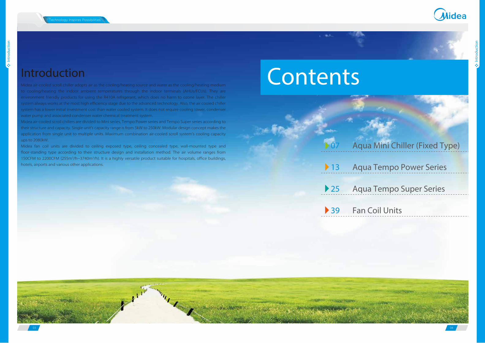
Introduction
Aqua Mini Chiller (Fixed Type)
Aqua Tempo Power Series
Aqua Tempo Super Series
Fan Coil Units
07
13
25
39
Midea air-cooled scroll chiller adopts air as the cooling/heating source and water as the cooling/heating medium
to cooling/heating the indoor ambient temperatures through the indoor terminals (AHUs/FCUs). They are
environment friendly products for using the R410A refrigerant, which does no harm to ozone layer. The chiller
system always works at the most high efficiency stage due to the advanced technology. Also, the air cooled chiller
system has a lower initial investment cost than water cooled system. It does not require cooling tower, condenser
water pump and associated condenser water chemical treatment system.
Midea air-cooled scroll chillers are divided to Mini series, Tempo Power series and Tempo Super series according to
their structure and capacity. Single unit’s capacity range is from 5kW to 250kW. Modular design concept makes the
application from single unit to multiple units. Maximum combination air-cooled scroll system’s cooling capacity
ups to 2080kW.
Midea fan coil units are divided to ceiling exposed type, ceiling concealed type, wall-mounted type and
floor-standing type according to their structure design and installation method. The air volume ranges from
150CFM to 2200CFM (255m3/h~3740m3/h). It is a highly versatile product suitable for hospitals, office buildings,
hotels, airports and various other applications.
Contents

Ramada Plaza (Five Star)
05 06
Refe
renc
e Pr
ojec
ts
Refe
renc
e Pr
ojec
ts
O�ce
Governmental porject
Transportation
Industry
Vimpelcom O�ce Building
Country:
City:
Total Capacity:
Outdoor Unit:
Indoor Unit:
Completion Year:
Total Floor Area:
Russia
Yaroslavl
186 HP
Air-cooled scroll chiller
FCU
2012
5,300 m²
Reference Projects
Hotel&Restaurant
Country:
City:
Total Capacity:
Outdoor Unit:
Indoor Unit:
Completion Year:
Total Floor Area:
China
Shunde
2,500 RT
Water-cooled screw chiller
AHU & FCU
2009
50,000 m²
Country:
City:
Total Capacity:
Outdoor Unit:
Indoor Unit:
Completion Year:
Sheraton Bandara Resort Hotel(Five Star)
Indonesia
Jakarta
1,050 RT
Air-cooled screw chiller
FCU
2011
Country:
City:
Total Capacity:
Outdoor Unit:
Indoor Unit:
Completion Year:
Total Floor Area:
Police Station Vazisubani
Georgia
Vazisubani
1,180 HP
Air-cooled scroll chiller
FCU
2011
11,000 m²
Country:
City:
Total Capacity:
Outdoor Unit:
Indoor Unit:
Completion Year:
Mozambique Capital Airport
Mozambique
Maputo
4,000 RT
Air-cooled screw chiller
FCU & AHU
2012
Castagna Univel Factory
Country:
City:
Total Capacity:
Outdoor Unit:
Indoor Unit:
Completion Year:
Total Floor Area:
Italy
Milan
250 HP
Air-cooled scroll chiller
FCU
2011
3,000 m²
07 08
Aqu
a M
ini C
hille
r
Aqu
a M
ini C
hille
r
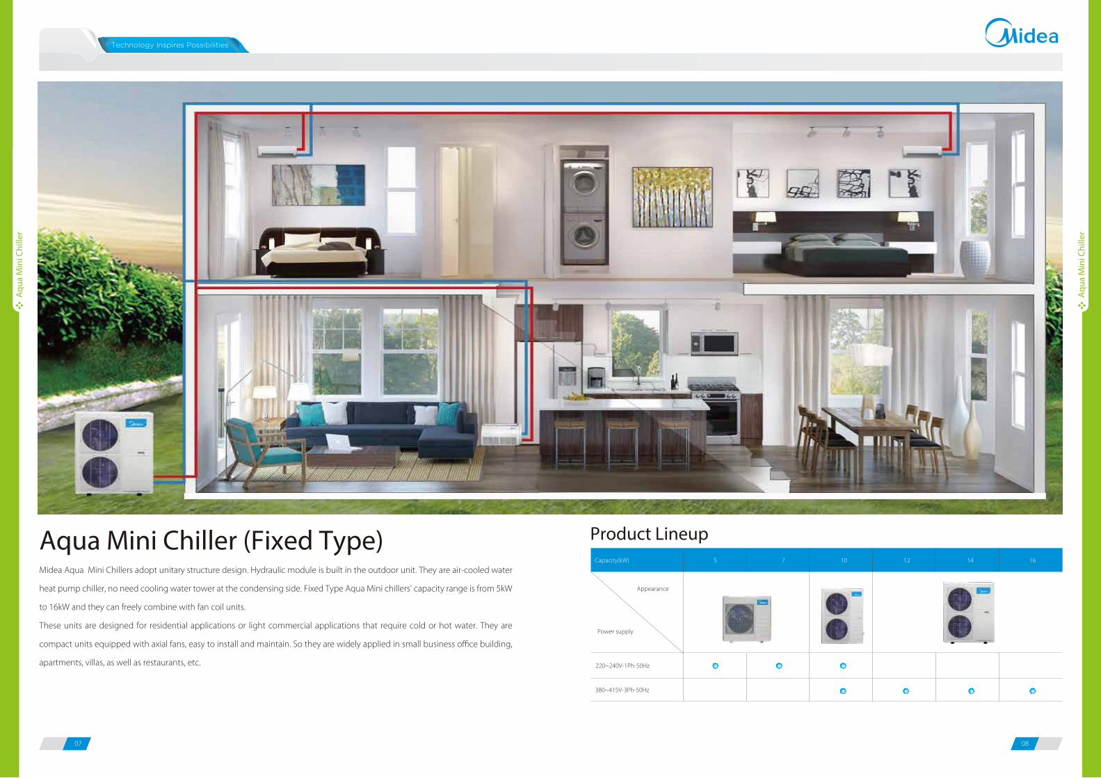
Midea Aqua Mini Chillers adopt unitary structure design. Hydraulic module is built in the outdoor unit. They are air-cooled water
heat pump chiller, no need cooling water tower at the condensing side. Fixed Type Aqua Mini chillers' capacity range is from 5kW
to 16kW and they can freely combine with fan coil units.
These units are designed for residential applications or light commercial applications that require cold or hot water. They are
compact units equipped with axial fans, easy to install and maintain. So they are widely applied in small business office building,
apartments, villas, as well as restaurants, etc.
Aqua Mini Chiller (Fixed Type) Product Lineup
Power supply
Appearance
Capacity(kW)
220~240V-1Ph-50Hz
380~415V-3Ph-50Hz
5 7 10 12 14 16

09 10
Aqu
a M
ini C
hille
r
Aqu
a M
ini C
hille
r
FeaturesEasy installationCompact structure design saves you much installation space.
Air Cooled Mini Chillers are equipped with axial fans that can be
installed directly outdoors.
Hydronic module is built-in the outdoor unit, which is including
water pump, expansion tank and plate heat-exchanger.
High performance heat exchanger
New design
Original design
High efficiency inner-threaded pipe, enhance heat transfer.
Reduce air resistance
Hydrophilic fins + inner-threaded pipes
The new designed window fins enlarge the heat-exchanging area, decrease the air resistance, save more power and enhance
heat exchange performance.
Hydrophilic film fins and inner-threaded copper pipes optimize heat exchange efficiency.
The specially coated blue fins enhance durability and protect against corrosion from air, water and other corrosive agents,
assures a longer coil service life.
High e�ciency plate heat exchanger
Plate heat exchanger uses metal plates to transfer heat between refrigerant and water. The fluids are exposed to a much larger
surface area because the fluids spread out over the plates, so both heat transfer efficiency and heat exchanger speed are
greatly improved.
Multi protections including voltage protection, current protection, anti-freezing protection and water flow protection ensure
system safety running.
Water pump
Pressure difference
switch
Expansion tank
Plate heat-exchanger
Easy control User-friendly electronic controller is built in the outdoor unit.LCD remote controller is optional.Auto-restart function.
Emergency switch and water pressure gauge are equipped with to ensure system safety.
Water pressure gaugeEmergency switchElectronic controllerElectronic controller Remote controller
Speci�cations
1. Cooling: Chilled water inlet/outlet temperature: 12/7°C,outdoor ambient temperature 35°C DB.2. Heating: Warm water inlet/outlet temperature: 40/45°C,outdoor ambient temperature 7°C DB/6°C WB.3. 1m away in semi-anechonic room.
Refrigerant inlet
Refrigerant outlet
Water inlet
Water outlet
220~240V-1Ph-50HzMGC-F05W/N1 MGC-F07WN1 MGC-F10WN1
V/Ph/Hz 220-240/1/50 220-240/1/50 220-240/1/50
Capacity kW 5.0 7.2 10.5
Input kW 1.9 2.8 3.6
Capacity kW 5.5 7.7 12.0
Input kW 2.0 2.8 4.0
A 11.7 16.7 25.7
Rotary Rotary Fixed Scroll
Quantity Pieces 1 1 1
Type Fin-coil Fin-coil Fin-coil
AC Motor AC Motor AC Motor
Quantity of fan motor Pieces 1 1 2
Air flow m3/h 5,563 5,624 6,500
Plate type Plate type Plate type
Water flow m3/h 0.86 1.24 1.74
Water pressure drop kPa 21 35 44
Pump head m 6 6 8
Water volume L/min 4 4 7.5
L 2 2 3
R410A R410A R410A
Charged volume kg 1.6 2.1 3.0
Capillary Capillary Capillary
dB(A) 55 56 60
mm 990×966×354 990×966×354 940×1245×360
mm 1,120×1,100×435 1,120×1,100×435 1,058×1,300×438
kg 83/89 94/100 138/145
kPa 500/150 500/150 500/150
Pipe connections Water inlet/outlet mm DN25 DN25 DN32
Cooling °C 10~43 10~43 10~43
Heating °C -15-24 -15-24 -15-24
Cooling °C 10~20 10~20 10~20
Heating °C 30~50 30~50 30~50
Model
Power supply
Cooling1
Heating2
Max. input current
Fan motor type
Water s ide heat
exchanger
Type
Air s ide heat exchanger
CompressorType
Electronic controller (standard), remote controller (optional)
Water pump
Expansion tank volume
Type
Sound pressure level3
Throttle type
Refrigerant
Ambient temperature range
Water outlet
temperature range
Unit net dimension (W×H×D)
Packing dimension (W×H×D)
Net/ Gross weight
The Max. and Min. wate rinlet pressure
Controller

11 12
Aqu
a M
ini C
hille
r
Aqu
a M
ini C
hille
r
1. Cooling: Chilled water inlet/outlet temperature: 12/7°C,outdoor ambient temperature 35°C DB.2. Heating: Warm water inlet/outlet temperature: 40/45°C,outdoor ambient temperature 7°C DB/6°C WB. 3. 1m away in semi-anechonic room.
MGC-F05W/N1 MGC-F07W/N1
MGC-F10W/N1 MGC-F10W/SN1
MGC-F12W/SN1 MGC-F14W/SN1 MGC-F16W/SN1
Dimensions (unit: mm)
1245
962
940
600
360
376
400
1012
990
624
354
366
396
1249
1092
460
430
420
1070698
966
380~415V-3Ph-50HzMGC-F10W/SN1 MGC-F12W/SN1 MGC-F14W/SN1 MGC-F16W/SN1
V/Ph/Hz 380-415/ 3/50 380-415/ 3/50 380-415/ 3/50 380-415/ 3/50
Capacity kW 10.5 12.0 14.0 16.0
Input kW 3.9 4.4 4.9 6.4
Capacity kW 12.0 14.0 16.1 18.0
Input kW 4.2 4.6 5.2 6.4
A 8.3 9.1 10.5 14.3
Fixed Scroll Fixed Scroll Fixed Scroll Fixed Scroll
Quantity Pieces 1 1 1 1
Fin-coil Fin-coil Fin-coil Fin-coil
AC Motor AC Motor AC Motor AC Motor
Quantity of fan motor Pieces 2 2 2 2
Air flow m3/h
m3/h
7,000 7,000 7,000 7,000
Plate type Plate type Plate type Plate type
Water flow 1.72 2 2.4 2.8
Water pressure drop kPa 44 40 34 38
Pump head m 8 8 8 8
Water volume L/min 7.5 7.5 7.5 7.5
L 3 3 3 3
R410A R410A R410A R410A
Charged volume kg 2.7 3.0 3.6 4.2
Capillary Capillary Capillary Capillary
dB(A) 58 59 60 60
mm 940×1,245×360 1,070×1,249×420 1,070×1,249×420 1,070×1,249×420
mm 1,058×1,300×438 1,188×1,385×498 1,188×1,385×498 1,188×1,385×498
kg 131/139 137/145 145/160 151/165
kPa 500/150 500/150 500/150 500/150
Pipe connections Water inlet/outlet mm DN32 DN32 DN32 DN32
Cooling °C 10~43 10~43 10~43 10~43
Heating °C -15-24 -15-24 -15-24 -15-24
Cooling °C 10~20 10~20 10~20 10~20
Heating °C 30~50 30~50 30~50 30~50
Model
Power supply
Cooling1
Heating2
Max. input current
Electronic controller (standard), remote controller (optional)
Water pump
Expansion tank volume
Type
Sound pressure level3
Ambient temperature range
Water outlet temperaturet
range
Unit net dimension (W×H×D)
Packing dimension (W×H×D)
Net/ Gross weight
The Max. and Min. wate rinlet pressure
Controller
Type
Air s ide heat exchanger
Compressor
Throttle type
Refrigerant
Fan motor type
Water heat exchanger
Type
Type

13 14
Aqu
a Te
mpo
Pow
er
Aqu
a Te
mpo
Pow
er
Midea Aqua Tempo Power chillers adopt V shape heat exchanger and single unit’s capacity from 30kW to 250kW.They are divided
to PS, PS-LA and PS-HMLA series according to their operation ambient temperature range and inner components. PS-LA series are
products with low ambient temperature cooling function and PS-HMLA series are products built-in with hydraulic module based
on PS-LA products.
Product Lineup
Aqua Tempo PowerAir Cooled Scroll Chiller
Series
Appearance
Capacity (kW) 30 65 130 200 250
50Hz PS (F/D) / / / / /
50Hz PS-LA(F/D) / / / / /
50Hz PS-HMLA (F/D) / / / / /
60Hz PS (F/D) / / / / /
PS: Standard Power Series PS-LA: Power Series with low ambient temperature cooling functionPS-HMLA: Power Series with low ambient temperature cooling function and built-in with hydraulic moduleF: Product adopted fixed speed scroll compressorD: Product adopted digital scroll compressor

15 16
Aqu
a Te
mpo
Pow
er
Aqu
a Te
mpo
Pow
er
17 basic models with cooling capacity ranging from 30kW to 250kW, combination model’s maximum capacity ups to 2000kW.
Freely combine with fan coil units and air handling units. Project owners may choose the best types according to their design
taste (for interior) or functional needs.
Wide operation ambient temperature range
For the Aqua Tempo Power chillers with low ambient temperature cooling function, the running ambient temperature down
to -10°C both in cooling and heating.
FeaturesWide application range
250kW 250kW 2000kW
Max 8 modules
Cassette type
Air handling units
Celling & Floor
Floor standing
Wall mounted
Duct type
Advanced technologyDigital scroll technology
PWM valve
DischargeFixed Scroll
Suction
Orbiting Scroll
The digital scroll compressor utilizes axial compliant sealing technology to precisely adjust the axial motion range of the stator
scroll pan. And there is an additional connecting by-pass between the suction inlet and the pressure bore at the floating sealing
point of axial stator.
Operation Principle of Digital Scroll Compressor
When the PWM solenoid valve is open, the pressure in the pressure bore is
released. The pressure in the compression bore is higher than that top of
the stator, then the stator axis of the compressor will move upward a little.
So high pressure bore and low pressure inlet is connected and the unload-
ing is achieved.
When the PWM solenoid valve is closed, two stators engage to achieve an
airtight state and loading functionality.
The compressor can adjust the ratio of ON to OFF freely to control the refrig-
erant output of the compressor.
Provides 40 million times the average service life of PWM
solenoid valves, making sure the long life of compressor.
Guarantees high efficiency by applying axial-compliant
sealing technology.
Provides 10% to 100% stepless capacity output to
precisely control room temperature.
Less electromagnetic interference, no EMC problem.
Compressor motor
Suction
Discharge
High reliability in high ambient temperatures is guaranteed by the low pressure design of the compressor motor.
Effectively cools the compressor motor by suction gas.
Creates stronger resistance to the compressor liquid hammer.
Provides strong reliability in high ambient temperatures.
Inverter EMC Regulation Digital Scroll System
5th
7th
11th
13th
17th
19th 0 1 2 3 4 5
Ampere
EMW
CO
OLI
NG
HEA
TIN
G
-10˚C
46˚C
-10˚C
21˚C
46˚C 27˚C 27˚C-15˚C
Wide range of outlet water temperature
For the Aqua Tempo Power chillers with low ambient temperature cooling function, the lowest outlet temperature in cooling
mode is 0°C.17°C0°C
COOLING MODE
50°C22°C
HEATING MODE
17 18
Aqu
a Te
mpo
Pow
er
Aqu
a Te
mpo
Pow
er
The new designed window fins enlarge the heat-exchanging area, decrease the air resistance, save more power and enhance heat
exchange performance.
Hydrophilic film fins and inner-threaded copper pipes optimize heat exchange efficiency.
The specially coated blue fins enhance durability and protect against corrosion from air, water and other corrosive agents, assures
a longer coil service life.
Touch key wire controller as standard accessory to control the chillers.
Remote control functions for convenient operation.
There are ON/OFF, Heat/Cool and Alarm terminals ports on PCB, connect switches from these terminal ports and remote
control functions can be easily realized.
In a combination system, if one module failed, other modules can be back-up instead of the failed one for continuing operation.
30kW and 65kW products are compliance with ErP directive, including both PS series and PS-LA series. The seasonal space heating
energy efficiency classes for 30kW models are A rated and 65kW models are A+ rated.
Individual hydraulic module compatible with cooling capacity of 65kW and 130kw is optional. Water box, expansion water tank,
two water pumps are built in the hydraulic box. The integral structure design saves you much installation labor and cost.
Flexible installation
Compliance with ErP directive
Easy control
High performance heat exchanger
Back-up functions
Individual hydraulic module optional New design
Original design
High efficiency inner-threaded pipe, enhance heat transfer.
Reduce air resistance
Hydrophilic fins + inner-threaded pipes
Master SlaveMaster Slave
MGCSL-F (D) 30W/RN1are equipped with a hydraulic module integrated into
the unit chassis, limiting the installation to straight-forward operations like
connection of the power supply, the water supply and the air distribution
terminals.
Built-in hydraulic module
HM/II-65S
HM/II-130S
Note: When use the remote control function, the wired controller will be invalid for ON/OFF and mode selection.
19 20
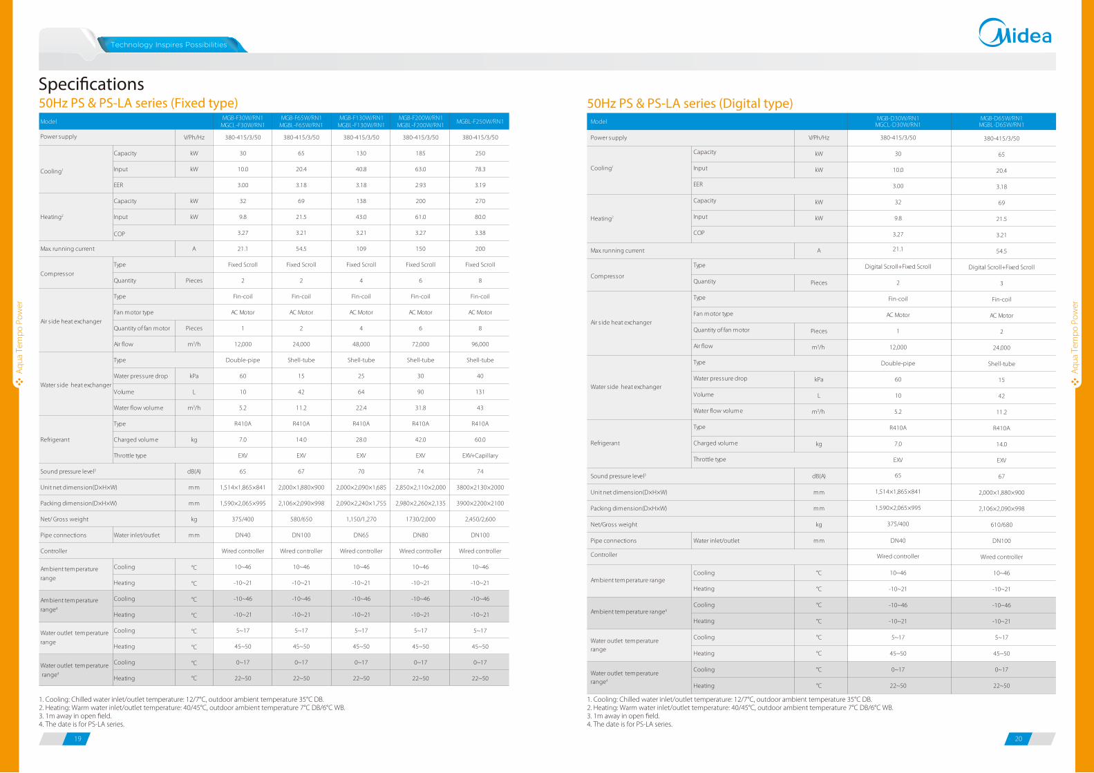
50Hz PS & PS-LA series (Fixed type)Speci�cations
Aqu
a Te
mpo
Pow
er
Aqu
a Te
mpo
Pow
er
1. Cooling: Chilled water inlet/outlet temperature: 12/7°C, outdoor ambient temperature 35°C DB.2. Heating: Warm water inlet/outlet temperature: 40/45°C, outdoor ambient temperature 7°C DB/6°C WB.3. 1m away in open field.4. The date is for PS-LA series.
1. Cooling: Chilled water inlet/outlet temperature: 12/7°C, outdoor ambient temperature 35°C DB.2. Heating: Warm water inlet/outlet temperature: 40/45°C, outdoor ambient temperature 7°C DB/6°C WB.3. 1m away in open field.4. The date is for PS-LA series.
50Hz PS & PS-LA series (Digital type)MGB-F30W/RN1
MGCL-F30W/RN1MGB-F65W/RN1
MGBL-F65W/RN1MGB-F130W/RN1
MGBL-F130W/RN1MGB-F200W/RN1
MGBL-F200W/RN1MGBL-F250W/RN1
V/Ph/Hz 380-415/3/50 380-415/3/50 380-415/3/50 380-415/3/50 380-415/3/50
Capacity kW 30 65 130 185 250
Input kW 10.0 20.4 40.8 63.0 78.3
3.00 3.18 3.18 2.93 3.19
Capacity kW 32 69 138 200 270
Input kW 9.8 21.5 43.0 61.0 80.0
3.27 3.21 3.21 3.27 3.38
A 21.1 54.5 109 150 200
Fixed Scroll Fixed Scroll Fixed Scroll Fixed Scroll Fixed Scroll
Quantity Pieces 2 2 4 6 8
Fin-coil Fin-coil Fin-coil Fin-coil Fin-coil
AC Motor AC Motor AC Motor AC Motor AC Motor
Quantity of fan motor Pieces 1 2 4 6 8
Air flow m3/h 12,000 24,000 48,000 72,000 96,000
Double-pipe Shell-tube Shell-tube Shell-tube Shell-tube
Water pressure drop kPa 60 15 25 30 40
Volume L 10 42 64 90 131
Water flow volume m3/h 5.2 11.2 22.4 31.8 43
Type R410A R410A R410A R410A R410A
Charged volume kg 7.0 14.0 28.0 42.0 60.0
EXV EXV EXV EXV EXV+Capillary
dB(A) 65 67 70 74 74
mm 1,514×1,865×841 2,000×1,880×900 2,000×2,090×1,685 2,850×2,110×2,000 3800×2130×2000
mm 1,590×2,065×995 2,106×2,090×998 2,090×2,240×1,755 2,980×2,260×2,135 3900×2200×2100
kg 375/400 580/650 1,150/1,270 1730/2,000 2,450/2,600
Pipe connections Water inlet/outlet mm DN40 DN100 DN65 DN80 DN100
Wired controller Wired controller Wired controller Wired controller Wired controller
Cooling °C 10~46
Heating °C -10~21
Cooling °C -10~46
Heating °C -10~21
Cooling °C 5~17
Heating °C 45~50
Cooling °C 0~17
Heating °C 22~50
10~46
-10~21
-10~46
-10~21
5~17
45~50
0~17
22~50
10~46
-10~21
-10~46
-10~21
5~17
45~50
0~17
22~50
10~46
-10~21
-10~46
-10~21
5~17
45~50
0~17
22~50
10~46
-10~21
-10~46
-10~21
5~17
45~50
0~17
22~50
Model
Cooling1
Heating2
Power supply
Max. running current
EER
COP
Net/ Gross weight
Type
Water s ide heat exchanger
Type
CompressorType
Fan motor type
Refrigerant
Sound pressure level3
Air s ide heat exchanger
Throttle type
Unit net dimension(D×H×W)
Packing dimension(D×H×W)
Ambient temperature
range
Ambient temperature
range4
Water outlet temperature
range
Water outlet temperature
range4
Controller
MGB-D30W/RN1MGCL-D30W/RN1
MGB-D65W/RN1MGBL-D65W/RN1
V/Ph/Hz 380-415/3/50 380-415/3/50
Capacity kW 30 65
Input kW 10.0 20.4
3.00 3.18
Capacity kW 32 69
Input kW 9.8 21.5
3.27 3.21
A 21.1 54.5
Digital Scroll+Fixed Scroll Digital Scroll+Fixed Scroll
Quantity Pieces 2 3
Fin-coil Fin-coil
AC Motor AC Motor
Quantity of fan motor Pieces 1 2
Air flow m3/h 12,000 24,000
Double-pipe Shell-tube
Water pressure drop kPa 60 15
Volume L 10 42
Water flow volume m3/h 5.2 11.2
Type R410A R410A
Charged volume kg 7.0 14.0
EXV EXV
dB(A) 65 67
mm 1,514×1,865×841 2,000×1,880×900
mm 1,590×2,065×995 2,106×2,090×998
kg 375/400 610/680
Pipe connections Water inlet/outlet mm DN40 DN100
Wired controller Wired controller
Cooling °C 10~46
Heating °C -10~21
Cooling °C -10~46
Heating °C -10~21
Cooling °C 5~17
Heating °C 45~50
Cooling °C 0~17
Heating °C 22~50
10~46
-10~21
-10~46
-10~21
5~17
45~50
0~17
22~50
Model
Power supply
Max. running current
Throttle type
Type
Water s ide heat exchanger
Type
Compressor
Type
Fan motor type
Refrigerant
Cooling1
Heating2
COP
EER
Air s ide heat exchanger
Controller
Water outlet temperaturerange
Water outlet temperaturerange4
Net/Gross weight
Unit net dimension(D×H×W)
Packing dimension(D×H×W)
Ambient temperature range
Ambient temperature range4
Sound pressure level3
Aqu
a Te
mpo
Pow
er
Aqu
a Te
mpo
Pow
er
21 22
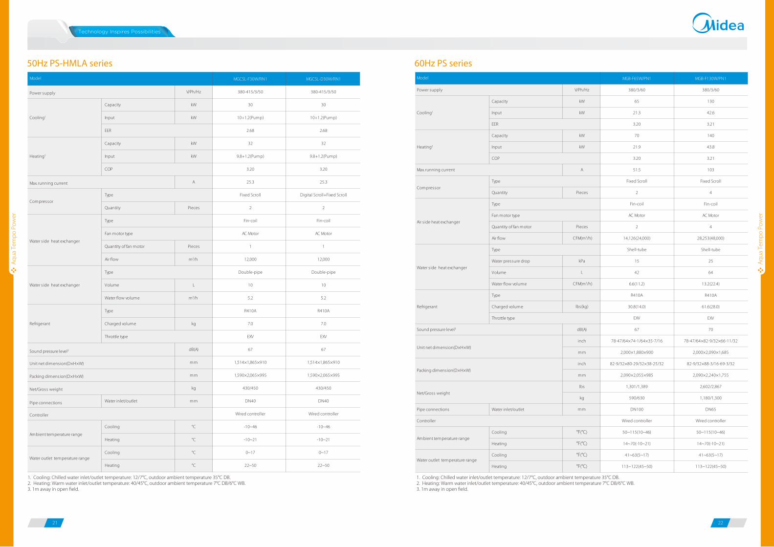
50Hz PS-HMLA series
1. Cooling: Chilled water inlet/outlet temperature: 12/7°C, outdoor ambient temperature 35°C DB.2. Heating: Warm water inlet/outlet temperature: 40/45°C, outdoor ambient temperature 7°C DB/6°C WB.3. 1m away in open field.
60Hz PS series
1. Cooling: Chilled water inlet/outlet temperature: 12/7°C, outdoor ambient temperature 35°C DB.2. Heating: Warm water inlet/outlet temperature: 40/45°C, outdoor ambient temperature 7°C DB/6°C WB.3. 1m away in open field.
MGCSL-F30W/RN1 MGCSL-D30W/RN1
V/Ph/Hz 380-415/3/50 380-415/3/50
Capacity kW 30 30
Input kW 10+1.2(Pump) 10+1.2(Pump)
2.68 2.68
Capacity kW 32 32
Input kW 9.8+1.2(Pump) 9.8+1.2(Pump)
3.20 3.20
A 25.3 25.3
Fixed Scroll Digital Scroll+Fixed Scroll
Quantity Pieces 2 2
Fin-coil Fin-coil
AC Motor AC Motor
Quantity of fan motor Pieces 1 1
Air flow m3/h 12,000 12,000
Double-pipe Double-pipe
Volume L 10 10
Water flow volume m3/h 5.2 5.2
Type R410A R410A
Charged volume kg 7.0 7.0
EXV EXV
dB(A) 67 67
mm 1,514×1,865×910 1,514×1,865×910
mm 1,590×2,065×995 1,590×2,065×995
kg 430/450 430/450
Pipe connections Water inlet/outlet mm DN40 DN40
Wired controller Wired controller
Cooling °C -10~46
Heating °C -10~21
Cooling °C 0~17
Heating °C 22~50
-10~46
-10~21
0~17
22~50
Refrigerant
Model
Cooling1
Heating2
Power supply
Max. running current
EER
Controller
Sound pressure level3
Ambient temperature range
Water outlet temperature range
COP
Water s ide heat exchanger
Throttle type
Unit net dimension(D×H×W)
Packing dimension(D×H×W)
Type
Water s ide heat exchanger
Type
Net/Gross weight
Compressor
Type
Fan motor type
MGB-F65W/PN1 MGB-F130W/PN1
V/Ph/Hz 380/3/60 380/3/60
Capacity kW 65 130
Input kW 21.3 42.6
3.20 3.21
Capacity kW 70 140
Input kW 21.9 43.8
3.20 3.21
A 51.5 103
Fixed Scroll Fixed Scroll
Quantity Pieces 2 4
Fin-coil Fin-coil
AC Motor AC Motor
Quantity of fan motor Pieces 2 4
Air flow CFM(m3/h) 14,126(24,000) 28,253(48,000)
Shell-tube Shell-tube
Water pressure drop kPa 15 25
Volume L 42 64
Water flow volume CFM(m3/h) 6.6(11.2) 13.2(22.4)
Type R410A R410A
Charged volume lbs(kg) 30.8(14.0) 61.6(28.0)
EXV EXV
dB(A) 67 70
inch 78-47/64×74-1/64×35-7/16 78-47/64×82-9/32×66-11/32
mm 2,000×1,880×900 2,000×2,090×1,685
inch 82-9/32×80-29/32×38-25/32 82-9/32×88-3/16-69-3/32
mm 2,090×2,055×985 2,090×2,240×1,755
lbs 1,301/1,389 2,602/2,867
kg 590/630 1,180/1,300
Pipe connections Water inlet/outlet mm DN100 DN65
Wired controller Wired controller
Cooling °F(°C) 50~115(10~46) 50~115(10~46)
Heating °F(°C) 14~70(-10~21) 14~70(-10~21)
Cooling °F(°C) 41~63(5~17) 41~63(5~17)
Heating °F(°C) 113~122(45~50) 113~122(45~50)
Model
Heating2
Power supply
Max. running current
Cooling1
EER
Throttle type
COP
Type
Water s ide heat exchanger
Type
Compressor
Type
Fan motor type
Refrigerant
Air s ide heat exchanger
Controller
Sound pressure level3
Ambient temperature range
Water outlet temperature range
Net/Gross weight
Unit net dimension(D×H×W)
Packing dimension(D×H×W)

Aqu
a Te
mpo
Pow
er
Aqu
a Te
mpo
Pow
er
23 24
200kW module
B
AF
C
E
D
250kW module
B
AF
C
E
D
65kW module
CFD
EA
B
Dimensions (Unit:mm)30kW module
D
E
F
C
B
A
Model A B C D E F
MGB-F(D)30W/RN1MGBL-F(D)30W/RN1
MGCSL-F(D)30W/RN1
1514 841 1865 115 315 172
1514 910 1865 100 317 557
MGB-F(D)65W/RN1MGBL-F(D)65W/RN1MGB-F65W/PN1
2000 900 1880 350 506 1420
MGB-F130W/RN1MGBL-F130W/RN1MGB-F130W/PN1
2000 1685 2080 350 506 1420
MGB-F200W/RN1MGBL-F200W/RN1
2850 2000 2110 347 506 2156
MGBL-F250W/RN1 3800 2000 2130 1235 573 2156
130kW module
D F C
EA
B
25 26
Aqu
a Te
mpo
Sup
er
Aqu
a Te
mpo
Sup
er
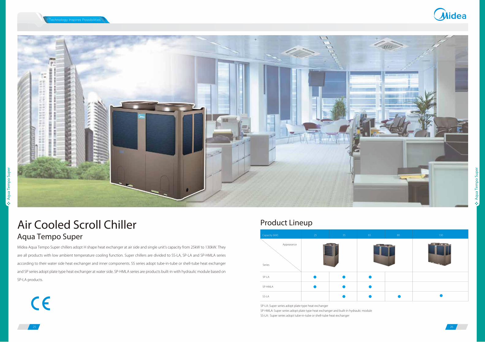
Air Cooled Scroll Chiller
Midea Aqua Tempo Super chillers adopt H shape heat exchanger at air side and single unit’s capacity from 25kW to 130kW. They
are all products with low ambient temperature cooling function. Super chillers are divided to SS-LA, SP-LA and SP-HMLA series
according to their water side heat exchanger and inner components. SS series adopt tube-in-tube or shell-tube heat exchanger
and SP series adopt plate type heat exchanger at water side. SP-HMLA series are products built-in with hydraulic module based on
SP-LA products.
Product Lineup
Aqua Tempo Super
Series
Appearance
Capacity (kW) 25
SP-LA
SP-HMLA
SS-LA
35 65 80 130
SP-LA: Super series adopt plate type heat exchanger
SP-HMLA: Super series adopt plate type heat exchanger and built-in hydraulic module
SS-LA: Super series adopt tube-in-tube or shell-tube heat exchanger
27 28
Aqu
a Te
mpo
Sup
er
Aqu
a Te
mpo
Sup
er
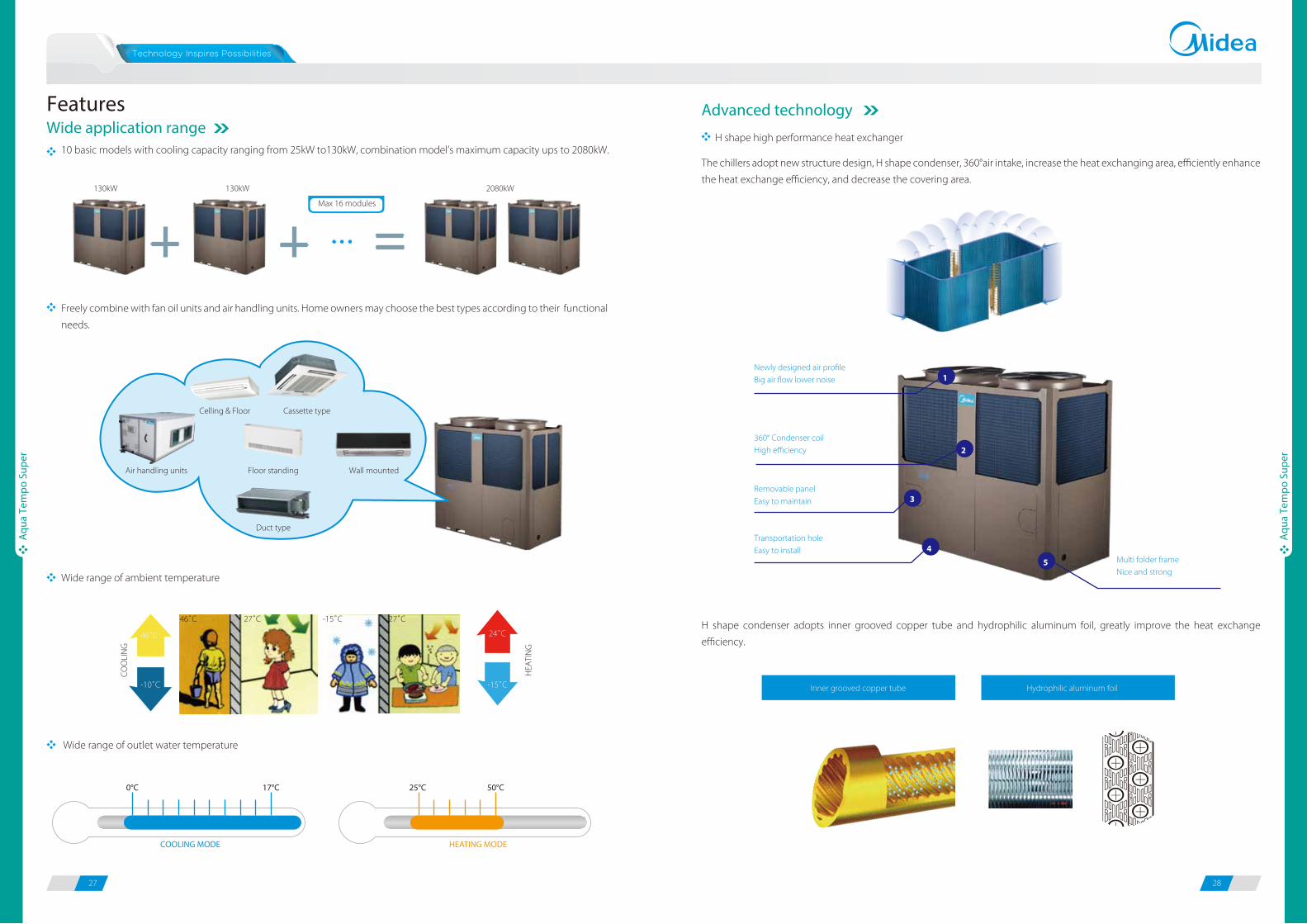
10 basic models with cooling capacity ranging from 25kW to130kW, combination model’s maximum capacity ups to 2080kW.The chillers adopt new structure design, H shape condenser, 360°air intake, increase the heat exchanging area, efficiently enhance
the heat exchange efficiency, and decrease the covering area.
H shape condenser adopts inner grooved copper tube and hydrophilic aluminum foil, greatly improve the heat exchange
efficiency.
Freely combine with fan oil units and air handling units. Home owners may choose the best types according to their functional
needs.
FeaturesWide application range
Advanced technology
H shape high performance heat exchanger
Max 16 modules
130kW 130kW 2080kW
Cassette type
Wall mounted
Duct type
Air handling units
Celling & Floor
Floor standing
Wide range of ambient temperature
CO
OLI
NG
HEA
TIN
G
-10˚C
46˚C
-15˚C
24˚C
46˚C 27˚C 27˚C-15˚C
Wide range of outlet water temperature
Newly designed air profileBig air flow lower noise
360° Condenser coilHigh efficiency
Removable panelEasy to maintain
Transportation holeEasy to install
Multi folder frameNice and strong
4
3
2
1
5
Hydrophilic aluminum foilInner grooved copper tube
17°C0°C
COOLING MODE
50°C25°C
HEATING MODE

29 30
Aqu
a Te
mpo
Sup
er
Aqu
a Te
mpo
Sup
er
Patented liquid distribution components to maximize performance and minimize defrost impact.
500 steps EXV plus capillary for stable and accurate gas flow control.
Fast respond resulting in higher efficiency and improved reliability.In one combination module, all slave units operate as alternative in cycle duty to keep equal running time, realize higher stability,
better reliability and longer lifespan.
For example, five modules combination, no.1 is master unit, others are slave units.
High reliabilityEXV for more precisely flow control
Alternative cycle duty operation
Back-up functions
Reliable protections
High efficiency plate heat exchanger (For SP series)
Tube-in-tube & shell-tube heat exchanger (For SS series)
0%
25%
50%
75%
100%
Refrigerant inlet
Refrigerant outlet
Water inlet
Water outletPlate heat exchanger uses metal plates to transfer heat between
refrigerant and water. The fluids are exposed to a much larger surface
area because the fluids spread out over the plates, so both heat transfer
efficiency and heat exchanger speed are greatly improved.
Multi protections including voltage protection, current protection,
anti-freezing protection and water flow protection ensure system
safety running.
For shell-tube heat exchanger, the module adopts the new helical baffle design to avoid the rectangular place of water dead
zone, greatly improve the heat exchange efficiency.
Chilled water inletRefrigerant inlet
Chilled water outlet
Refrigerant outlet
Flat baffle plate
Helical baffle
Water dead zone
1 3 452
1 2 3 45
1 3 2 45
In a combination system, if one module failed, other modules can be back-up instead of the failed one for continuing operation.
Slave
Master Slave
Master
Multiple protections are adopted to ensure system stable running.
Power phases sequence protection
Frequently ON/OFF protection of compressor
System anti-freezing protection in winter
Evaporator low temperature protection in cooling
Over-current protection
of compresor
Air discharge temperature protection of compressor
Sensor malfunction protection
Water flow protectionSystem high temperature protection
High/low pressure protection of compressor

31 32
Aqu
a Te
mpo
Sup
er
Aqu
a Te
mpo
Sup
er
Flexible installation
Intelligent defrosting technology Individual hydronic module optional
Compact structure design
Model alternative defrosting technology ensures little fluctuation on water temperature.
Manual defrosting program is available for service purpose.
Super power chiller adopts compact structure design, light weight, easy for transportation and installation.
For SP series, built-in hydraulic module products are available. The modules are fully integrated and built-in expansion tank, plate
heat exchanger, water circulating pump, etc. It saves you much installation space and cost.
T min Time saving
Time
Hea
ting
capa
city
Midea Fast Defrosting Traditional defrosting
7 minutes less!
Built-in hydronic module
Inner grooved copper tubeCapacity & efficiency increase
Big air flow but low noise fanBig torque high efficiency fan motor
Control boxEasy to maintain
Scroll compressorHigh efficiencyLow noise
EXV500 steps
Helical baffle Efficiency increase 10%
Multi folder frameLow vibration. Durable and stable
7
1
6
5
4
3
2
Touch key wire controller as standard accessory to control the chillers.
There are ON/OFF, Heat/Cool and Alarm terminals ports on PCB, connect switches from these terminal ports and remote control
functions can be easily realized.
Individual hydronic module compatible with cooling capacity of 65kW and 130kW is optional.
Water box, expansion water tank, two water pumps are built in the hydronic box. The integral structure design saves you much
installation labor and cost.
Easy control
HM/II-65S
HM/II-130S
Hydraulic Module
Remote control functions for convenient operation
Note: When use the remote control function, the wired controller will be invalid for ON/OFF and mode selection.

MC-SP25-RN1L MC-SP35-RN1L MC-SP65-RN1L
V/Ph/Hz 380-415/3/50 380-415/3/50 380-415/3/50
Capacity kW 25 35 65
Input kW 8.0 11.5 20.4
3.13 3.04 3.19
Capacity kW 26 37 69
Input kW 8.0 11.3 21.5
3.27 3.27 3.21
A 20.7 28.8 54.5
Fixed Scroll Fixed Scroll Fixed Scroll
Quantity Pieces 1 1 1
Fin-coil Fin-coil Fin-coil
AC Motor AC Motor AC Motor
Quantity of fan motor Pieces 1 1 2
Air flow m3/h
m3/h
13,500 13,500 27,000
Plate type Plate type Plate type
Water pressure drop kPa 77 63 55
Volume L 1.89 2.77 4.44
Water flow volume 4.3 6 11.2
R410A R410A R410A
Charged volume kg 3.1 5.4 10
EXV EXV EXV
dB(A) 65 65 67
mm 1,020×1,770×980 1,020×1,770×980 2,000×1,770×960
mm 1,070×1,900×1030 1,070×1,900×1030 2,090×1,890×1030
kg 276/286 304/314 470/490
Pipe connections Water inlet/outlet mm DN40 DN40 DN50
Wired controller Wired controller Wired controller
Cooling °C -10~46 -10~46 -10~46
Heating °C -15~24 -15~24 -15~24
Cooling °C 5~17 5~17 5~17
Heating °C 25~50 25~50 25~50
Model
Power supply
Max. running current
Ambient temperature
range
Water outlet
temperature range
Heating2
Cooling1
EER
COP
Throttle type
Type
Fan motor type
Water s ide heat
exchanger
Type
Controller
Compressor
Sound pressure level3
Unit net dimension(D×H×W)
Packing dimension(D×H×W)
Net/Gross weight
Type
Refrigerant
Air s ide heat exchanger
Type
SP-LA series
33 34
Aqu
a Te
mpo
Sup
er
Aqu
a Te
mpo
Sup
er
Speci�cationsSP-HMLA series
1. Cooling: Chilled water inlet/outlet temperature: 12/7°C, outdoor ambient temperature 35°C DB.2. Heating: Warm water inlet/outlet temperature: 40/45°C, outdoor ambient temperature 7°C DB/6°C WB.3. 1m away in open field.
1. Cooling: Chilled water inlet/outlet temperature: 12/7°C, outdoor ambient temperature 35°C DB.2. Heating: Warm water inlet/outlet temperature: 40/45°C, outdoor ambient temperature 7°C DB/6°C WB. 3. 1m away in open field.
MC-SP25M-RN1L MC-SP35M-RN1L MC-SP65M-RN1L
V/Ph/Hz 380-415/3/50 380-415/3/50 380-415/3/50
Capacity kW 25 35 65
Input kW 9.2 12.7 22.6
2.72 2.76 2.88
Capacity kW 26 37 69
Input kW 9.2 12.5 23.7
2.84 3.04 2.91
A 24.0 32.1 60.4
Fixed Scroll Fixed Scroll Fixed Scroll
Quantity Pieces 1 1 1
Fin-coil Fin-coil Fin-coil
AC Motor AC Motor AC Motor
Quantity of fan motor Pieces 1 1 2
Air flow m3/h 13,500 13,500 27,000
Plate type Plate type Plate type
Volume L 1.89 2.77 4.44
Water flow volume m3/h 4.3 6 11.2
R410A R410A R410A
Charged volume kg 3.1 5.4 10
EXV EXV EXV
dB(A) 65 65 67
mm 1,020×1,770×980 1,020×1,770×980 2,000×1,770×960
mm 1,070×1,900×1,030 1,070×1,900×1,030 2,090×1,890×1,030
kg 313/323 343/353 540/560
Pipe connections Water inlet/outlet mm DN40 DN40 DN50
Wired controller Wired controller Wired controller
Cooling °C -10~46 -10~46 -10~46
Heating °C -15~24 -15~24 -15~24
Cooling °C 5~17 5~17 5~17
Heating °C 25~50 25~50 25~50
Model
Power supply
Max. running current
Fan motor type
Air s ide heat exchanger
Type
Type
Throttle type
Ambient temperature
range
Water outlet
temperature range
EER
Cooling1
Heating2
COP
Water s ide heat
exchanger
Type
Controller
Unit net dimension(D×H×W)
Packing dimension(D×H×W)
Sound pressure level3
Net/Gross weight
Compressor
Type
Refrigerant
Aqu
a Te
mpo
Sup
er
Aqu
a Te
mpo
Sup
er
SS-LA series
35 36
1. Cooling: Chilled water inlet/outlet temperature: 12/7°C, outdoor ambient temperature 35°C DB.2. Heating: Warm water inlet/outlet temperature: 40/45°C, outdoor ambient temperature 7°C DB/6°C WB.3. 1m away in open field.
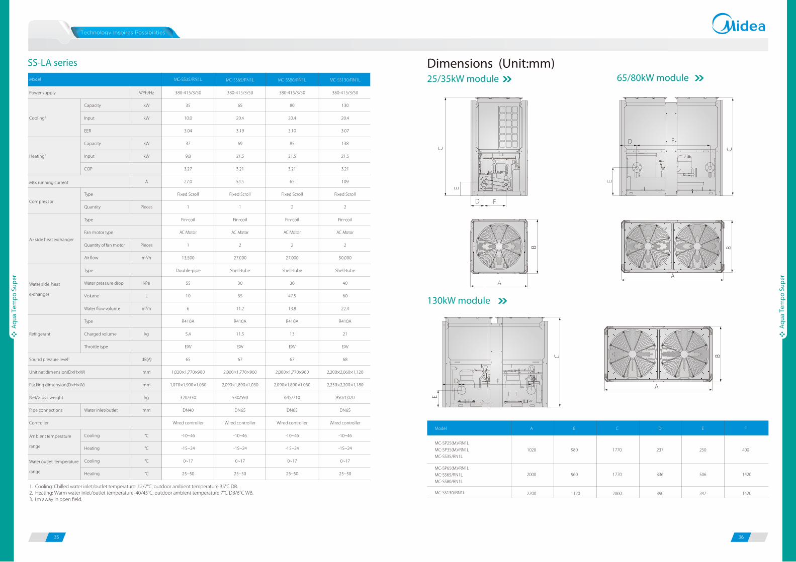
Dimensions (Unit:mm)25/35kW module 65/80kW module
C
FD
E
F
C
E
D
130kW module
A
B
A
B
B
AF
C
E
D
MC-SS130/RN1L
MC-SP25(M)/RN1L
MC-SP35(M)/RN1L
MC-SS35/RN1L
MC-SP65(M)/RN1L
MC-SS65/RN1L
MC-SS80/RN1L
Model A B C D E F
1020 980 1770 237 250 400
2000 960 1770 336 506 1420
2200 1120 2060 390 347 1420
MC-SS35/RN1L MC-SS65/RN1L MC-SS80/RN1L MC-SS130/RN1L
V/Ph/Hz 380-415/3/50 380-415/3/50 380-415/3/50 380-415/3/50
Capacity kW 35 65 80 130
Input kW 10.0 20.4 20.4 20.4
3.04 3.19 3.10 3.07
Capacity kW 37 69 85 138
Input kW 9.8 21.5 21.5 21.5
3.27 3.21 3.21 3.21
A 27.0 54.5 65 109
Fixed Scroll Fixed Scroll Fixed Scroll Fixed Scroll
Quantity Pieces 1 1 2 2
Fin-coil Fin-coil Fin-coil Fin-coil
AC Motor AC Motor AC Motor AC Motor
Quantity of fan motor Pieces 1 2 2 2
Air flow m3/h 13,500 27,000 27,000 50,000
Double-pipe Shell-tube Shell-tube Shell-tube
Water pressure drop kPa 55 30 30 40
Volume L 10 35 47.5 60
Water flow volume m3/h 6 11.2 13.8 22.4
R410A R410A R410A R410A
Charged volume kg 5.4 11.5 13 21
EXV EXV EXV EXV
dB(A) 65 67 67 68
mm 1,020×1,770×980 2,000×1,770×960 2,000×1,770×960 2,200×2,060×1,120
mm 1,070×1,900×1,030 2,090×1,890×1,030 2,090×1,890×1,030 2,250×2,200×1,180
kg 320/330 530/590 645/710 950/1,020
Pipe connections Water inlet/outlet mm DN40 DN65 DN65 DN65
Wired controller Wired controller Wired controller Wired controller
Cooling °C -10~46
Heating °C -15~24
Cooling °C 0~17
Heating °C 25~50
-10~46
-15~24
0~17
25~50
-10~46
-15~24
0~17
25~50
-10~46
-15~24
0~17
25~50
Model
Power supply
Max. running current
Type
Refrigerant
Fan motor type
Air s ide heat exchanger
Type
Ambient temperature
range
Water outlet temperature
range
Cooling1
Heating2
EER
COP
Type
Throttle type
Unit net dimension(D×H×W)
Packing dimension(D×H×W)
Water s ide heat
exchanger
Type
Controller
Sound pressure level3
Net/Gross weight
Compressor
37 38
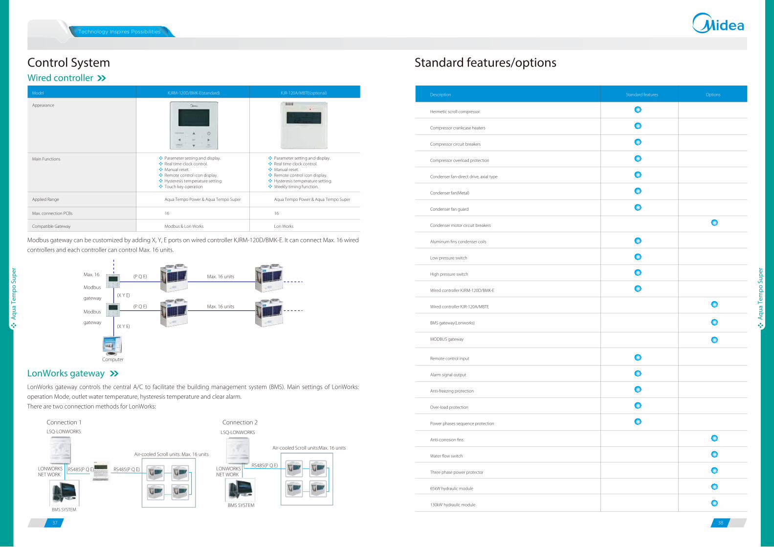
Standard features/optionsWired controllerControl System
Hermetic scroll compressor
Compressor crankcase heaters
Compressor circuit breakers
Compressor overload protection
Condenser fan-direct drive, axial type
Condenser fan(Metal)
Condenser fan guard
Condenser motor circuit breakers
Aluminum fins condenser coils
Low pressure switch
High pressure switch
Wired controller KJRM-120D/BMK-E
Wired controller KJR-120A/MBTE
BMS gateway(Lonworks)
MODBUS gateway
Description Standard features Options
Remote control input
Alarm signal output
Anti-freezing protection
Over-load protection
Power phases sequence protection
Anti-corrosion fins
Water flow switch
Three phase power protector
65kW hydraulic module
130kW hydraulic module
Aqu
a Te
mpo
Sup
er
Aqu
a Te
mpo
Sup
er
Model KJRM-120D/BMK-E(standard) KJR-120A/MBTE(optional)
Appearance
Main Functions Parameter setting and display. Real time clock control.Manual reset.Remote control icon display.Hysteresis temperature setting.Touch key operation
Parameter setting and display.Real time clock control.Manual reset.Remote control icon display.Hysteresis temperature setting. Weekly timing function.
Applied Range Aqua Tempo Power & Aqua Tempo Super Aqua Tempo Power & Aqua Tempo Super
Max. connection PCBs 16 16
Compatible Gateway Modbus & Lon Works Lon Works
Max. 16 (P Q E)
(P Q E)
Modbus
gateway
Modbus
gateway
Computer
(X Y E)
(X Y E)
Max. 16 units
Max. 16 units
LonWorks gateway controls the central A/C to facilitate the building management system (BMS). Main settings of LonWorks:
operation Mode, outlet water temperature, hysteresis temperature and clear alarm.
There are two connection methods for LonWorks:
Modbus gateway can be customized by adding X, Y, E ports on wired controller KJRM-120D/BMK-E. It can connect Max. 16 wired
controllers and each controller can control Max. 16 units.
LonWorks gateway
Air-cooled Scroll units: Max. 16 units
LONWORKSNET WORK
LSQ-LONWORKS
BMS SYSTEM
RS485(P Q E)
Air-cooled Scroll units:Max. 16 units
LSQ-LONWORKS
BMS SYSTEM
RS485(P Q E)
Connection 1 Connection 2
RS485(P Q E) LONWORKSNET WORK
39 40
Fan
Coil
Uni
ts
Fan
Coil
Uni
ts
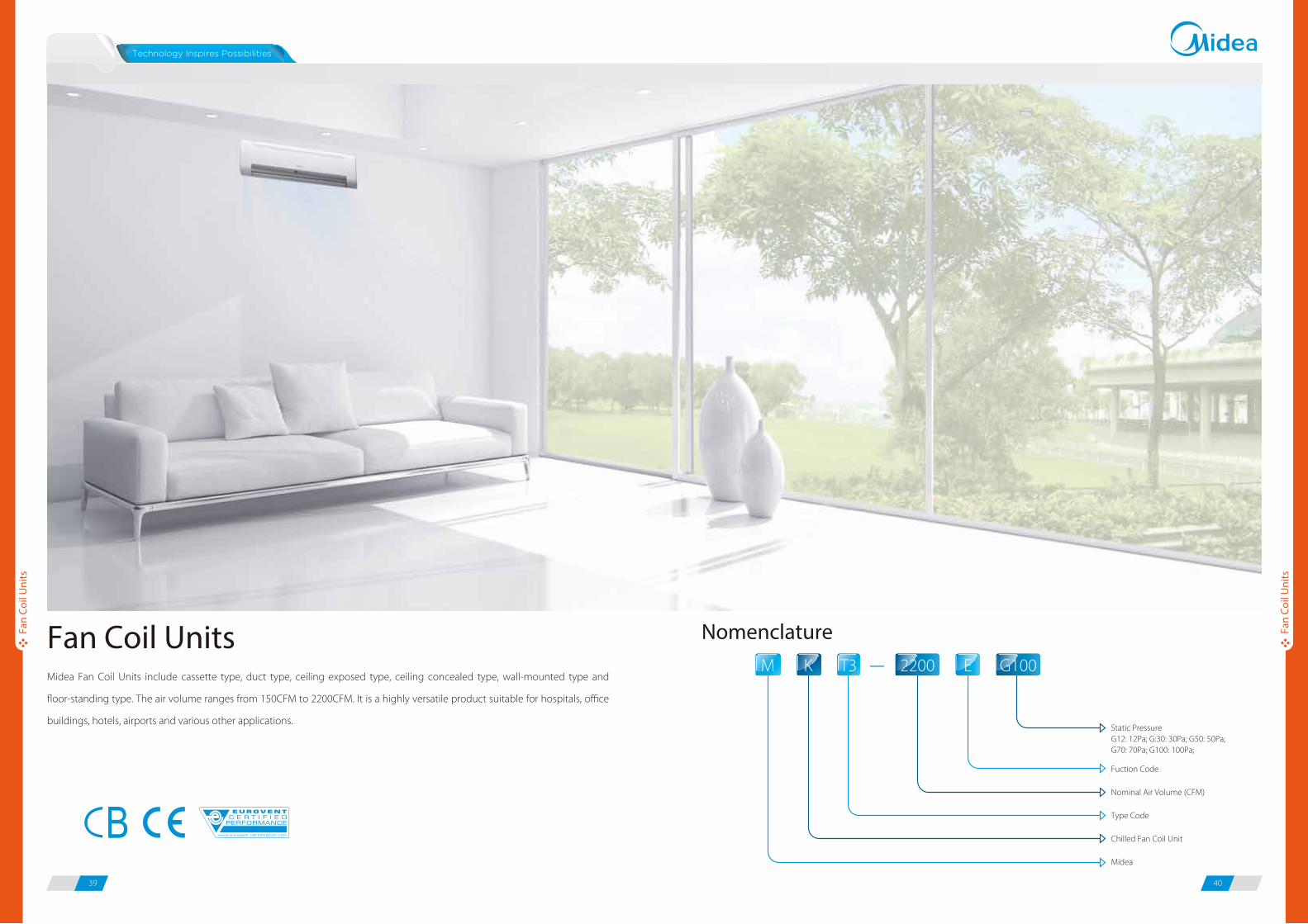
Midea Fan Coil Units include cassette type, duct type, ceiling exposed type, ceiling concealed type, wall-mounted type and
floor-standing type. The air volume ranges from 150CFM to 2200CFM. It is a highly versatile product suitable for hospitals, office
buildings, hotels, airports and various other applications.
Fan Coil UnitsM -K T3 E2200 G100
Type Code
Midea
Static PressureG12: 12Pa; G:30: 30Pa; G50: 50Pa;G70: 70Pa; G100: 100Pa;
Fuction Code
Nominal Air Volume (CFM)
Chilled Fan Coil Unit
Nomenclature

41 42
Fan
Coil
Uni
ts
Fan
Coil
Uni
ts
Product Lineup
2-Pipe FCUs
Air volume (CFM)
1-way cassette
4-way cassette
Wall mounted
Ceiling & floor
Floor standing
150 200 250 300 400 450 500 600 750 800 850 900 950 1000 1200 1400 1500 1600 1800 2000 2200
Compact 4-way cassette
Duct
High static pressure Duct
4-Pipe FCUs
Air volume (CFM)
4-way cassette
Duct
200 300 400 500 600 750 800 850 950 1000 1200 1400 1500
Compact 4-way cassette
Note:
The standard power supply for all fan coil units is 220V-240V/50Hz; 208-230V/60Hz can be customized for all fan coil units.

43 44
Fan
Coil
Uni
ts
Fan
Coil
Uni
ts
Cassette Series
300/400CFM
600CFM
Compact 4-way Cassette
4-way Cassette
1-way Cassette
Compact design, ultra slim body with a minimum thickness of
153mm, especially suitable for narrow ceiling, such as in
lobbies and small meeting rooms.
153mm UItra thin
Min. 153mm Thickness
One direction air flow guarantees quick cooling, flexible installation
positioning.
One Direction Air Flow
High-lift PumpStandard built-in drain pump with 750mm pump head.
750mm
Single direction airflow,flexibly installed in various corners
One direction air flow
Speci�cations
Notes:1. H: High fan speed; M: Medium fan speed; L: Low fan speed.2. Cooling conditions: entering water 7°C, temperature rise 5°C, entering air temperature 27°C DB/19°C WB. Heating conditions: entering water 50°C, entering air temperature 20°C DB, the same water flow as the cooling conditios.3. Noise is tested in a semi-anechoic test room.
Power supply
Cooling
Power input (H/M/L)
Auxiliary electric heater (AEH)
Sound pressure level (H/M/L)
Coil
Pipe
connections
Capacity (H/M/L)
Water flow rate
Water pressure drop
Capacity (H/M/L)
Water pressure drop
Type
Quantity
Type
Quantity
Row
Max. working pressure
Diameter
Net dimensions (W×H×D)
Packing size (W×H×D)
Net weight
Gross weight
Net dimensions (W×H×D)
Packing size (W×H×D)
Net weight (non-AEH/with-AEH)
Gross weight (non-AEH/with-AEH)
Water inlet/outlet pipe
Drain pipe
V/Ph/Hz
m3/h
CFM
kW
L/h
kPa
kW
kPa
W
W
dB(A)
MPa
mm
mm
mm
kg
kg
mm
mm
kg
kg
inch
mm
510/450/400
300/270/240
3.04/2.79/2.56
520
14.0
5.13/4.69/4.04
9.0
32/22/15
750
36/34/32
1
2
1180x25x465
1232x107x517
3.5
5.2
1054x153x425
1155x245x490
12.8/13.1
16.6/17.1
630/560/500
370/330/300
3.79/3.58/3.38
650
20.0
6.41/5.86/5.11
16.0
40/30/25
750
37/35/34
1
2
1180x25x465
1232x107x517
3.5
5.2
1054x153x425
1155x245x490
12.8/13.1
16.6/17.1
1000/880/800
590/520/470
5.71/4.85/4.36
982
20.2
9.60/8.36/7.48
18.1
125/88/65
/
42/39/37
4
3
1420×10×755
1500×110×870
9
12
1200×198×655
1380×265×720
32.6
36.3
220-240/1/50
Low noise 3-speed fan motor
1
Centrifugal, forward-curved Blades
1.6
Φ7
RC1/2
ODΦ25
Model
ModelNon-AEH MKC-300R-B MKC-400R-B MKC-600HRN4
With-AEH MKC-300RA-B MKC-400RA-B /
Air flow (H/M/L)
Heating
Fan motor
Fan
Panel
Body
1-way Cassette

Fan
Coil
Uni
ts
Fan
Coil
Uni
ts
45 46
4-way Cassette
Various SelectionsVersions for 2/4 pipe systems.
Versions for compact/normal size.
4-way air supply panel is standard for 4-way cassette.
360°air supply panel is standard for compact 4-way cassette.
Stylish Panel with Large Air�ow Outlet
4-way panel 360°panel
For Compact Four-way Cassette: Extremely compact casing suits any
room's decor and requires little space for installation on a low ceiling.
Due to compact body and light weight, all models can be installed without
a hoist.
Safe factory-installed electric heater is optional.
Extended drainage pan is optional.
Wireless controller is standard, and wired controller is optional.
Standard built-in drain pump with 750mm pump head for normal
size and 500mm for compact size.
575mm
261mm
575mm
Compact Design, Easy Installation
Various Accessories Selections
High-lift Drain Pump
Fresh air can enter through the cassette unit so you can enjoy even
fresher air in a room.
Fresh Air Intake
750mm
2-Pipe 4-Way Cassette
Notes:1. H: High fan speed; M: Medium fan speed; L: Low fan speed.2. Cooling conditions: entering water 7°C, temperature rise 5°C, entering air temperature 27°C DB/19°C WB. Heating conditions: entering water 45°C, temperature drop 5°C, entering air temperature 20°C DB.3. Noise is tested in a semi-anechoic test room.
Power supply
Cooling
Power input (H/M/L)Auxiliary electric heater (AEH)Sound pressure level (H/M/L)
Coil
Pipe connections
Capacity (H/M/L)Water flow rateWater pressure dropCapacity (H/M/L)Water pressure drop
TypeQuantityTypeQuantityRowMax. working pressureDiameterNet dimensions (W×H×D)Packing size (W×H×D)Net weightGross weightNet dimensions (W×H×D)Packing size (W×H×D)Net weight (non-AEH/with-AEH)Gross weight (non-AEH/with-AEH)Water inlet/outlet pipeDrain pipe
V/Ph/Hzm3/hCFMkWL/hkPakWkPaWW
dB(A)
MPammmmmmkgkg
mmmmkgkg
inchmm
1024/733/460603/431/271
5.64/4.76/3.95980 29.9
5.86/4.43/3.4921.0
156/105/922100
45/41/36
840×230×840900×260×900
25/2730/32
220-240/1/501267/1006/796
746/592/4686.04/4.73/3.93
1204 30.0
7.24/5.49/4.3137.2
140/110/1002100
46/42/37Low noise 3-speed fan motor
1Centrifugal, forward-curved blades
12
1.6Φ7
950×45×9501035×90×1035
69
840×230×840900×260×900
25/2730/32RC3/4
ODΦ32
1460/1228/1041859/723/613
7.66/6.80/5.921250 35.0
8.01/7.11/6.6022.8
170/140/1202850
47/43/38
840×300×840900×330×900
30.5/3336.2/39
Air flow (H/M/L)
Heating
Fan motor
Fan
Panel
Body
ModelNon-AEH MKA-600R MKA-750R MKA-850RWith-AEH MKA-600RA MKA-750RA MKA-850RA
Power supply
Cooling
Power input (H/M/L)Auxiliary electric heater (AEH)Sound pressure level (H/M/L)
Coil
Pipe connections
Capacity (H/M/L)Water flow rateWater pressure dropCapacity (H/M/L)Water pressure drop
TypeQuantityTypeQuantityRowMax. working pressureDiameterNet dimensions (W×H×D)Packing size (W×H×D)Net weightGross weightNet dimensions (W×H×D)Packing size (W×H×D)Net weight (non-AEH/with-AEH)Gross weight (non-AEH/with-AEH)Water inlet/outlet pipeDrain pipe
V/Ph/Hzm3/hCFMkWL/hkPakWkPaWW
dB(A)
MPammmmmmkgkg
mmmmkgkg
inchmm
1562/1314/1113919/773/655
8.55/7.58/6.611414 23.0
9.86/8.00/7.7428.2
190/160/1302850
48/44/39
2
30.5/3336.2/39
220-240/1/501606/1427/1224
945/840/7207.85/5.98/5.22
1787 42.5
8.76/7.09/6.5744.5
210/140/4202850
49/45/40Low noise 3-speed fan motor
1Centrifugal, forward-curved blades
12
1.6Φ7
950×45×9501035×90×1035
69
840×300×840900×330×900
30.5/3336.2/39RC3/4
ODΦ32
1844/1466/12771085/863/752
10.43/8.70/7.642219 38.8
11.9/9.61/8.4647.1
210/150/120/
50/46/41
3
31.836
Non-AEH MKA-950R MKA-1200R MKA-1500RWith-AEH MKA-950RA MKA-1200RA /
Model
Air flow (H/M/L)
Heating
Fan motor
Fan
Panel
Body

Fan
Coil
Uni
ts
Fan
Coil
Uni
ts
47 48
4-Pipe 4-Way Cassette 2-Pipe Compact 4-Way Cassette
4-Pipe Compact 4-Way Cassette
ModelPower supply
Cooling
Heating
Power input (H/M/L)Sound pressure level (H/M/L)
Coil
Pipe connections
Capacity (H/M/L)Water flow rateWater pressure dropCapacity (H/M/L)Water flow rateWater pressure drop
TypeQuantityTypeQuantityRowMax. working pressureDiameterNet dimensions (W×H×D)Packing size (W×H×D)Net weightGross weightNet dimensions (W×H×D)Packing size (W×H×D)Net weight Gross weightWater inlet/outlet pipeDrain pipe
V/Ph/Hzm3/hCFMkWL/hkPakWL/hkPaW
dB(A)
MPammmmmmkgkg
mmmmkgkg
inchmm
MKA-600F
1150/787/684680/470/410
4.99/4.01/3.71877 15.8
5.67/4.51/4.17574 26.2
111/70/5242/32/26
MKA-750F220-240/1/501270/897/740860/600/510
5.78/4.34/3.891020 20.4
6.69/4.98/4.35677 33.9
153/75/5544/34/28
Low noise 3-speed fan motor1
Centrifugal, forward-curved Blades12
1.6Φ7
950×45×9501035×90×1035
69
840×300×840900×307×900
3541
Cold water: RC3/4; Hot water: RC1/2ODΦ32
MKA-850F
1480/1163/965870/610/520
6.02/5.00/4.481061 21.3
6.85/5.70/5.53693 32.7
153/127/10946/36/30
Air flow (H/M/L)
Fan motor
Fan
Panel
Body
Notes:1. H: High fan speed; M: Medium fan speed; L: Low fan speed.2. Cooling conditions: entering water 7°C, temperature rise 5°C, entering air temperature 27°C DB/19°C WB. Heating conditions: entering water 65°C, temperature drop 10°C DB, entering air temperature 20°C DB.3. Noise is tested in a semi-anechoic test room.
Notes:1. H: High fan speed; M: Medium fan speed; L: Low fan speed.2. Cooling conditions: entering water 7°C, temperature rise 5°C, entering air temperature 27°C DB/19°C WB. Heating conditions(2 pipe): entering water 45°C, temperature drop 5°C, entering air temperature 20°C DB. Heating conditions(4 pipe): entering water 65°C, temperature drop 10°C DB, entering air temperature 20°C DB.3. Noise is tested in a semi-anechoic test room.
ModelPower supply
Cooling
Heating
Power input (H/M/L)Sound pressure level (H/M/L)
Coil
Pipe connections
Capacity (H/M/L)Water flow rateWater pressure dropCapacity (H/M/L)Water flow rateWater pressure drop
TypeQuantityTypeQuantityRowMax. working pressureDiameterNet dimensions (W×H×D)Packing size (W×H×D)Net weightGross weightNet dimensions (W×H×D)Packing size (W×H×D)Net weight Gross weightWater inlet/outlet pipeDrain pipe
V/Ph/Hzm3/hCFMkWL/hkPakWL/hkPaW
dB(A)
MPammmmmmkgkg
mmmmkgkg
inchmm
MKA-950F
1720/1278/11001010/700/6106.53/5.35/4.74
1152 31.6
7.20/6.17/5.39746 43.2
170/128/11047/38/32
2
3541
MKA-1200F220-240/1/50
1867/1448/11171090/760/6509.06/7.27/6.36
1596 39.6
9.95/7.91/7.511002 48.1
217/176/14148/40/34
Low noise 3-speed fan motor1
Centrifugal, forward-curved Blades13
1.6Φ7
950×45×9501035×90×1035
69
840×300×840900×307×900
3844
Cold water: RC3/4; Hot water: RC1/2ODΦ32
MKA-1500F
2100/1448/11171230/860/7409.61/7.29/6.37
1820 45.2
10.71/7.91/7.511085 54.7
234/160/12650/42/36
3
3844
Air flow (H/M/L)
Fan motor
Fan
Panel
Body
MKD-300 MKD-400 MKD-500
V/Ph/Hz
m3/h 560/490/380 690/540/440 840/570/470
CFM 330/288/224 406/318/259 494/335/277
Capacity (H/M/L) kW 2.86/2.50/2.14 3.52/3.00/2.65 4.28/3.45/2.92
Water flow rate L/h 516 636 774
Water pressure drop kPa 14 15 16
Capacity (H/M/L) kW 3.10/2.72/2.38 4.21/3.57/3.17 4.95/3.96/3.37
Water pressure drop kPa 15.4 16.7 19.2
W 50/40/30 70/50/40 90/50/40
dB(A) 36/33/28 42/39/32 45/42/34
Max. working pressure MPa
Diameter mm
Net dimensions (W×H×D) mm
Packing size (W×H×D) mm
Net weight kg
Gross weight kg
Net dimensions (W×H×D) mm
Packing size (W×H×D) mm
Net weight kg
Gross weight kg
Water inlet/outlet pipe inch
Drain pipe mm
Fan motorLow noise 4-speed fan motor
1
Power input (H/M/L)
Type
Quantity
Air flow (H/M/L)
Cooling
Heating
220-240/1/50
Sound pressure level (H/M/L)
Φ7
647×50×647
2.5
715×123×715
FanCentrifugal, forward-curved Blades
1
Type
Quantity
Row
Model
Power supply
Pipe connections
Body
G3/4
ODΦ25
575×261×575
16.5
670×290×670
20
4.5
2
Panel
Coil 1.6
MKD-300S MKD-400S MKD-500SV/Ph/Hz
m3/h 560/421/328 690/540/440 650/570/470CFM 330/248/193 406/318/259 383/335/276
Capacity (H/M/L) kW 1.97/1.78/1.54 2.73/2.30/1.89 3.31/2.64/2.30Water flow rate L/h 430 499 602Water pressure drop kPa 22 16 24Capacity (H/M/L) kW 3.05/2.72/2.42 3.79/3.17/2.81 4.21/3.32/2.81Water flow rate L/h 318 396 439Water pressure drop kPa 21.8 29.5 34.6
W 50/40/30 70/50/40 90/50/40dB(A) 36/33/28 42/39/32 45/42/34
Max. working pressure MPaDiameter mmNet dimensions (W×H×D) mmPacking size (W×H×D) mmNet weight kgGross weight kgNet dimensions (W×H×D) mmPacking size (W×H×D) mmNet weight kgGross weight kgWater inlet/outlet pipe inchDrain pipe mm
Power input (H/M/L)
Centrifugal, forward-curved Blades1
Coil 1.6Φ7
2
TypeQuantity
TypeQuantity
Row
Air flow (H/M/L)
Cooling
Heating
220-240/1/50ModelPower supply
4.5
Sound pressure level (H/M/L)
Fan motorLow noise 4-speed fan motor
1
Panel
647×50×647
2.5715×123×715
Fan
Body
Cold water: G3/4; Hot water: G1/2ODΦ25
16.520
575×261×575670×290×670
Pipe connections

49 50
Duct Series Duct
Various Selections
Versions for 2/4 pipe systems.
Versions for normal/large temperature difference systems.
2, 3 or 4 rows coil for 2-pipe systems.
Large range of available static pressure.
Wired controller is optional.
Four fan speeds are avaliable: low, medium, high and one reserved for more choice.
High E�ciency
Standard Return Air Plenum and Filter
Fresh air can enter through the duct unit so you can enjoy even
fresher air in a room.
Fresh Air Intake
Left and right hand piping connections are optional, flexible installation.
Flexible Installation
Duct
High Static Pressure Duct
District Cooling Duct
Standard return air plenum and filter guarantees clean air supply and stable air flow rate.
Fan
Coil
Uni
ts
Fan
Coil
Uni
ts
Highly efficient heat exchange for complete contranatant flow.

51 52
2-Row Duct 3-Row Duct
Notes:1. H: High fan speed; M: Medium fan speed; L: Low fan speed.2. The data are test under standard external static pressure. 3. Cooling conditions: entering water 7°C, temperature rise 5°C, entering air temperature 27°C DB/19°C WB. Heating conditions: entering water 45°C, temperature drop 5°C, entering air temperature 20°C DB.4. Noise is tested in a semi-anechoic test room.
Notes:1. H: High fan speed; M: Medium fan speed; L: Low fan speed.2. The data are test under standard external static pressure. 3. Cooling conditions: entering water 7°C, temperature rise 5°C, entering air temperature 27°C DB/19°C WB. Heating conditions: entering water 45°C, temperature rise 5°C, entering air temperature 20°C DB.4. Noise is tested in a semi-anechoic test room.
Fan
Coil
Uni
ts
Fan
Coil
Uni
ts
MKT2-200G12MKT2-200G30
MKT2-200EG30
MKT2-300G12MKT2-300G30
MKT2-300EG30
MKT2-400G12MKT2-400G30
MKT2-400EG30
MKT2-500G12MKT2-500G30
MKT2-500EG30
MKT2-600G12MKT2-600G30
MKT2-600EG30V/Ph/Hz
m3/h 353/304/220 504/392/273 576/403/313 850/634/419 1020/745/459CFM 208/179/129 297/231/161 339/237/184 500/373/247 600/438/270Pa
Capacity (H/M/L) kW 1.70/1.27/0.94 2.43/1.80/1.29 2.98/2.48/1.88 3.20/2.70/2.03 4.20/3.52/2.82Water flow rate L/h 344 464 619 757 946Water pressure drop kPa 5.2 11.4 19 22.2 14.1Capacity (H/M/L) kW 2.06/1.59/1.21 3.06/2.22/1.53 3.77/3.03/2.28 4.11/3.37/2.5 5.47/4.47/3.42Water pressure drop kPa 5.4 12.2 19.9 23.5 15.112Pa (H/M/L) W 34/30/30 55/45/39 66/61/54 88/76/64 106/84/6730Pa (H/M/L) W 49/39/36 65/56/48 70/63/55 97/79/67 121/99/84
W 550 650 1100 1100 160012Pa (H/M/L) dB(A) 36/34/29 38/33/29 38/35/31 39/36/32 40/36/3330Pa (H/M/L) dB(A) 41/37/31 41/37/32 42/39/33 45/41/34 46/41/35
1 1 1 1 1
1 2 2 2 2
Max. working pressure MPaDiameter mm
mm 741×241×522 841×241×522 941×241×522 941×241×522 1161×241×522mm 790×260×550 890×260×550 990×260×550 990×260×550 1210×260×550kg 13.9/15.4 16.5/18 19.2/20.7 19.2/20.7 22/24kg 16.2/17.7 19/20.5 21.6/23.1 21.6/23.1 25/27
inchmm
Gross weight (non-AEH/with-AEH)Water inlet/outlet pipeDrain pipe
Auxiliary electric heater (AEH)
Net dimensions (W×H×D)Packing size (W×H×D)Net weight (non-AEH/with-AEH)
Sound pressure level
Fan motor
220-240/1/50
1.6Φ9.52
Low noise 4-speed fan motor
2
Air flow (H/M/L)
G12 models: 12; G30 models: 30
Cooling
Model
Power supply
Standard external static pressure
TypeQuantityTypeQuantityRow
ODΦ24RC3/4
FanCentrifugal, forward-curved Blades
Coil
Heating
Power input
V/Ph/Hz
m3/hCFMPa
Capacity (H/M/L) kWWater flow rate L/hWater pressure drop kPaCapacity (H/M/L) kWWater pressure drop kPa12Pa (H/M/L) W30Pa (H/M/L) W
W12Pa (H/M/L) dB(A)30Pa (H/M/L) dB(A)
Max. working pressure MPaDiameter mm
mmmmkgkg
inchmm
Gross weight (non-AEH/with-AEH)Water inlet/outlet pipeDrain pipe
Auxiliary electric heater (AEH)
Net dimensions (W×H×D)Packing size (W×H×D)Net weight (non-AEH/with-AEH)
Sound pressure level
Fan motor
Air flow (H/M/L)
Cooling
Model
Power supply
Standard external static pressure
TypeQuantityTypeQuantityRow
Fan
Coil
Heating
Power input
MKT2-800G12MKT2-800G30
MKT2-800EG30
MKT2-1000G12MKT2-1000G30
MKT2-1000EG30
MKT2-1200G12MKT2-1200G30
MKT2-1200EG30
MKT2-1400G12MKT2-1400G30
MKT2-1400EG30
1388/1012/746 1774/1336/850 2171/1421/1244 2229/1690/1225817/600/439 1044/786/500 1277/836/732 1311/994/721
5.80/4.60/3.67 6.95/5.58/4.69 8.89/7.74/6.69 9.57/8.70/7.111290 1531 1858 211614.9 22.7 41 46.5
7.34/5.53/4.31 8.79/6.70/5.47 10.84/9.02/7.75 11.53/10.30/8.1516 24.4 41.8 56.1
140/129/108 189/151/125 225/173/143 237/201/180142/112/96 211/180/158 230/190/168 273/190/164
2200 2200 3200 320042/37/33 44/39/34 46/40/35 48/42/3746/41/36 47/43/37 48/44/38 49/44/39
2 2 2 2
4 4 4 4
1461×241×522 1566×241×522 1856×241×522 2022×241×5221510×260×550 1615×260×550 1905×260×550 2070×260×550
30.9/33.4 33.4/36.4 38.5/42 42.1/46.134.5/37 37/40 42/45.5 47.5/51.5
G12 models: 12; G30 models: 30
220-240/1/50
Low noise 4-speed fan motor
Centrifugal, forward-curved Blades
21.6
Φ9.52
RC3/4ODΦ24
MKT3-200G12MKT3-200G30
MKT3-200EG30
MKT3-300G12MKT3-300G30
MKT3-300EG30
MKT3-400G12MKT3-400G30
MKT3-400EG30
MKT3-500G12MKT3-500G30
MKT3-500EG30
MKT3-600G12MKT3-600G30
MKT3-600EG30V/Ph/Hz
m3/h 414/251/160 519/320/201 651/429/288 768/589/408 986/649/462CFM 244/148/94 305/188/118 383/252/169 452/347/240 580/382/272Pa
Capacity (H/M/L) kW 2.25/1.66/1.25 3.03/2.21/1.60 3.50/2.81/2.12 3.79/3.17/2.46 4.98/3.94/3.11Water flow rate L/h 378 533 688 791 998Water pressure drop kPa 12.6 26.1 13 15.1 29.4Capacity (H/M/L) kW 2.69/1.95/1.42 3.52/2.47/1.72 3.52/2.47/1.72 4.65/3.77/2.85 5.94/4.55/3.51Water pressure drop kPa 26.8 28 28 16.5 3112Pa (H/M/L) W 51/38/34 68/52/45 83/67/60 128/78/65 132/86/7330Pa (H/M/L) W 51/38/34 80/61/53 97/78/70 112/68/57 132/86/73
W 550 650 1100 1100 160012Pa (H/M/L) dB(A) 35/32/26 36/33/27 37/34/28 40/36/30 42/38/3230Pa (H/M/L) dB(A) 41/37/31 42/38/32 43/39/33 44/40/34 45/41/35
1 1 1 1 1
1 2 2 2 2
Max. working pressure MPaDiameter mm
mm 741×241×522 841×241×522 941×241×522 941×241×522 1161×241×522mm 790×260×550 890×260×550 990×260×550 990×260×550 1210×260×550kg 14.6/16.1 17/18.5 20.2/21.7 20.2/21.7 23/25kg 16.9/18.4 19.5/21 22.6/24.1 22.6/24.1 26/28
inchmm
Packing size (W×H×D)Net weight (non-AEH/with-AEH)Gross weight (non-AEH/with-AEH)
QuantityTypeQuantity
Fan
Coil3
1.6Φ9.52
RC3/4
Row
220-240/1/50
G12 models: 12; G30 models: 30
Centrifugal, forward-curved Blades
Low noise 4-speed fan motor
Model
Power supply
Standard external static pressure
Air flow (H/M/L)
Fan motor
Cooling
Heating
Power input
Sound pressure level
Type
Auxiliary electric heater (AEH)
ODΦ24Water inlet/outlet pipeDrain pipe
Net dimensions (W×H×D)
MKT3-800G12MKT3-800G30
MKT3-800EG30
MKT3-1000G12MKT3-1000G30
MKT3-1000EG30
MKT3-1200G12MKT3-1200G30
MKT3-1200EG30
MKT3-1400G12MKT3-1400G30
MKT3-1400EG30V/Ph/Hz
m3/h 1303/913/668 1635/1129/815 1884/1382/777 1937/1694/1289CFM 767/537/393 962/664/480 1109/813/457 1139/997/759Pa
Capacity (H/M/L) kW 7.10/5.66/4.51 7.82/6.40/4.98 8.98/7.49/6.13 10.17/9.37/7.83Water flow rate L/h 1410 1548 1892 2150Water pressure drop kPa 28.5 19.2 23 27Capacity (H/M/L) kW 8.08/6.30/4.94 9.68/7.53/5.86 10.92/8.69/6.86 12.46/11.31/9.27Water pressure drop kPa 29.7 23.2 23.6 2912Pa (H/M/L) W 151/126/112 214/135/115 258/172/147 335/270/23430Pa (H/M/L) W 151/126/112 214/135/115 298/199/170 335/270/234
W 2200 2200 3200 320012Pa (H/M/L) dB(A) 43/39/33 45/41/35 46/42/36 48/44/3830Pa (H/M/L) dB(A) 46/42/36 47/43/37 48/44/38 49/45/39
2 2 2 2
4 4 4 4
Max. working pressure MPaDiameter mm
mm 1461×241×522 1566×241×522 1856×241×522 2022×241×522mm 1510×260×550 1615×260×550 1905×260×550 2070×260×550kg 31.9/34.4 34.4/37.4 39.5/43 43.1/47.1kg 35.5/38 38.1/41.1 43/46.5 48.4/52.4
inchmm
Packing size (W×H×D)Net weight (non-AEH/with-AEH)Gross weight (non-AEH/with-AEH)
QuantityTypeQuantity
Fan
CoilRow
RC3/4ODΦ24
G12 models: 12; G30 models: 30
220-240/1/50
Low noise 4-speed fan motor
Centrifugal, forward-curved Blades
Model
Power supply
Standard external static pressure
Air flow (H/M/L)
Fan motor
Cooling
Heating
Power input
Sound pressure level
Type
Auxiliary electric heater (AEH)
Φ9.52
31.6
Water inlet/outlet pipeDrain pipe
Net dimensions (W×H×D)
With-AEH
Non-AEH
With-AEH
Non-AEH
With-AEH
Non-AEH
With-AEH
Non-AEH
53 54
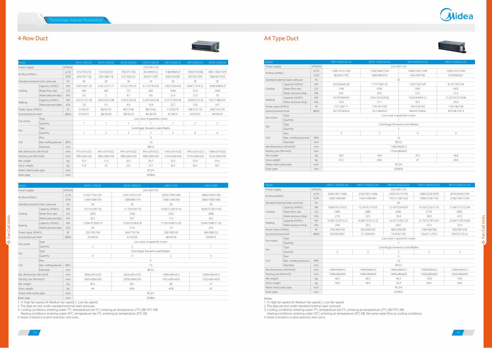
4-Row Duct A4 Type Duct
220-240/1/50
50
Low noise 3-speed fan motor
1
Centrifugal, forward-curved Blades
2
1.6
Φ9.52
1180x340x612
1310x380x693
RC3/4
ODΦ24
Model
Power supply
Standard external static pressure
Cooling
Power input (H/M/L)
Sound pressure level
Coil
Net dimensions (W×H×D)
Packing size (W×H×D)
Net weight
Gross weight
Water inlet/outlet pipe
Drain pipe
Capacity (H/M/L)
Water flow rate
Water pressure drop
Capacity (H/M/L)
Water pressure drop
Type
Quantity
Type
Quantity
Row
Max. working pressure
Diameter
V/Ph/Hz
m3/h
CFM
Pa
kW
L/h
kPa
kW
kPa
W
dB(A)
MPa
mm
mm
mm
kg
kg
inch
mm
MKT3-800G50-A4
1500/1412/1265
882/831/745
6.97/6.66/6.28
1198
19.0
9.57/9.09/8.43
16.9
151/130/111
49.7/47.8/45.6
3
38.3
47.2
MKT4-800G50-A4
1400/1342/1200
824/790/706
7.92/7.56/7.09
1363
13.5
10.42/9.89/9.12
39.7
144/124/105
48.4/47.9/46.6
4
39.3
47
MKT3-1000G50-A4
1700/1664/1554
1000/980/915
7.77/7.58/7.33
1336
24.5
10.61/10.25/9.82
21.1
174/147/130
50.1/48/45.8
3
39.8
48.6
MKT4-1000G50-A4
1650/1527/1405
970/900/827
8.15/7.93/7.54
1402
21.4
11.25/10.72/10.06
23.3
176/146/128
49.5/48.1/47.3
4
40.8
49.6
Notes:1. H: High fan speed; M: Medium fan speed; L: Low fan speed.2. The data are test under standard external static pressure. 3. Cooling conditions: entering water 7°C, temperature rise 5°C, entering air temperature 27°C DB/19°C WB. Heating conditions: entering water 45°C, temperature rise 5°C, entering air temperature 20°C DB.4. Noise is tested in a semi-anechoic test room.
Model
Power supply
Standard external static pressure
Cooling
Power input (H/M/L)
Sound pressure level
Coil
Net dimensions (W×H×D)
Packing size (W×H×D)
Net weight
Gross weight
Water inlet/outlet pipe
Drain pipe
Capacity (H/M/L)
Water flow rate
Water pressure drop
Capacity (H/M/L)
Water pressure drop
Type
Quantity
Type
Quantity
Row
Max. working pressure
Diameter
V/Ph/Hz
m3/h
CFM
Pa
kW
L/h
kPa
kW
kPa
W
dB(A)
MPa
mm
mm
mm
kg
kg
inch
mm
MKT4-1200G50-A4
2040/1851/1666
1200/1090/981
10.80/10.17/9.55
1890
27.8
14.30/13.23/12.22
24.8
320/284/250
50.9/50/48.5
2
1369x340x612
1490x380x693
46.3
56.4
MKT4-1400G50-A4
2420/1851/1666
1424/1090/981
12.14/10.17/9.55
2089
32.5
16.08/13.23/12.22
29.2
392/284/250
51.7/50/49.5
2
1369x340x612
1490x380x693
46.3
56.4
MKT4-1600G50-A4
220-240/1/50
2430/1917/1742
1431/1128/1025
50
12.19/10.54/9.87
2096
33.4
16.55/13.83/12.9
30.0
482/338/296
52.9/50.7/50
Low noise 3-speed fan motor
1
Centrifugal, forward-curved Blades
2
4
1.6
Φ9.52
1369x340x612
1490x380x693
46.3
56.4
RC3/4
ODΦ24
MKT4-1800G50-A4
3380/2239/1878
1990/1318/1105
16.16/12.35/11.01
2779
58.3
21.70/15.79/13.91
52.3
538/358/308
53.6/51.1/50.2
3
1500x340x612
1620x380x693
54.8
64.6
MKT4-2000G50-A4
3670/2544/2199
2160/1497/1294
17.34/13.75/12.44
2983
61.5
23.40/17.92/16.08
52.9
583/387/334
54.4/52.7/51.6
3
1500x340x612
1620x380x693
54.8
64.6
Notes:1. H: High fan speed; M: Medium fan speed; L: Low fan speed.2. The data are test under standard external static pressure. 3. Cooling conditions: entering water 7°C, temperature rise 5°C, entering air temperature 27°C DB/19°C WB. Heating conditions: entering water 50°C, entering air temperature 20°C DB, the same water flow as cooling conditions.4. Noise is tested in a semi-anechoic test room.
Fan
Coil
Uni
ts
Fan
Coil
Uni
ts
MKT4-200G30 MKT4-300G30 MKT4-400G30 MKT4-500G30 MKT4-600G30 MKT4-800G30 MKT4-1000G30
V/Ph/Hz
m3/h 415/318/218 519/320/201 700/571/392 853/699/522 1188/899/657 1303/913/668 1801/1405/1079
CFM 244/187/128 305/188/118 412/336/231 502/411/307 699/529/387 767/537/393 1060/827/635
Pa 30 30 30 30 30 30 30
Capacity (H/M/L) kW 2.09/1.69/1.26 2.92/2.37/1.71 3.72/3.19/2.41 4.11/3.73/3.03 5.82/5.05/4.03 6.84/5.72/4.52 8.80/6.88/6.27
Water flow rate L/h 430 568 757 826 1066 1514 1634
Water pressure drop kPa 2.6 5 8.1 9.8 21.4 12.3 18
Capacity (H/M/L) kW 2.67/2.15/1.58 3.62/2.81/2.08 4.39/3.76/2.8 5.02/4.36/3.48 6.77/5.76/4.49 8.00/6.7/5.23 9.61/7.98/6.54
Water pressure drop kPa 2.8 5.4 8.9 10.4 22.7 12.8 19.7
W 51/42/37 80/61/53 80/77/69 88/72/62 113/92/79 168/151/133 200/153/134
dB(A) 37/33/27 38/34/28 38/35/29 40/35/30 41/36/31 42/37/32 44/39/33
1 1 1 1 1 2 2
1 2 2 2 2 4 4
Max. working pressure MPa
Diameter mm
mm 741×241×522 841×241×522 941×241×522 941×241×522 1161×241×522 1461×241×522 1566×241×522
mm 790×260×550 890×260×550 990×260×550 990×260×550 1210×260×550 1510×260×550 1615×260×550
kg 15.3 17.5 20.7 20.7 23.5 32.9 35.4
kg 17.6 20 23.1 23.1 26.5 36.5 39.1
inch
mm
Model
220-240/1/50
Fan motorLow noise 4-speed fan motor
Power input (H/M/L)
Power supply
Standard external static pressure
Sound pressure level
Type
Quantity
Air flow (H/M/L)
Cooling
Heating
FanCentrifugal, forward-curved Blades
Coil
4
1.6
Φ9.52
Type
Quantity
Row
RC3/4
ODΦ24
Net dimensions (W×H×D)
Packing size (W×H×D)
Net weight
Gross weight
Water inlet/outlet pipe
Drain pipe
MKT4-1200G30 MKT4-1400G30 MKT4-1500 MKT4-2000
V/Ph/Hz
m3/h 2123/1714/1231 2181/1672/1221 2550/2100/1300 3400/2550/1700
CFM 1249/1009/724 1284/984/719 1500/1240/760 2000/1500/1000
Pa 30 30 30 30
Capacity (H/M/L) kW 10.71/9.29/7.32 11.15/9.20/7.41 13.50/11.50/10.10 18.00/15.30/13.50
Water flow rate L/h 2030 2236 2322 3096
Water pressure drop kPa 26.2 29.7 11.5 26.2
Capacity (H/M/L) kW 12.64/10.59/8.19 13.03/10.59/8.28 17.50/14.90/13.20 23.40/19.80/17.50
Water pressure drop kPa 29 31.8 10 24.3
W 225/185/160 264/179/156 236/189/165 360/288/252
dB(A) 45/40/34 47/42/36 48/44/39 50/46/41
2 2 1 1
4 4 2 3
Max. working pressure MPa
Diameter mm
mm 1856×241×522 2022×241×522 1369×342×612 1500×342×612
mm 1905×260×550 2070×260×550 1421×381×619 1552×381×619
kg 40.5 44.1 46 57
kg 44 49.4 49.8 61
inch
mm
Model
Φ9.52
RC3/4
ODΦ24
220-240/1/50
Low noise 4-speed fan motor
Centrifugal, forward-curved Blades
4
1.6
Fan motor
Power input (H/M/L)
Power supply
Standard external static pressure
Sound pressure level
Type
Quantity
Air flow (H/M/L)
Cooling
Heating
Fan
Coil
Type
Quantity
Row
Net dimensions (W×H×D)
Packing size (W×H×D)
Net weight
Gross weight
Water inlet/outlet pipe
Drain pipe
Fan
Fan motor
Heating
Air flow (H/M/L)
Fan
Fan motor
Heating
Air flow (H/M/L)

55 56
High Static Pressure Duct District Cooling Duct
Model
Power supply
Standard external static pressure
Cooling
Power input (H/M/L)
Sound pressure level
Coil
Net dimensions (W×H×D)
Packing size (W×H×D)
Net weight
Gross weight
Water inlet/outlet pipe
Drain pipe
Capacity (H/M/L)
Water flow rate
Water pressure drop
Type
Quantity
Type
Quantity
Row
Max. working pressure
Diameter
V/Ph/Hz
m3/h
CFM
Pa
kW
L/h
kPa
W
dB(A)
MPa
mm
mm
mm
kg
kg
inch
mm
MKS4-200G30
430/380/340
253/224/200
30
2.05/1.742/1.55
196
10
47/38/33
38/33/27
1
741×241×522
790×260×550
15.3
17.6
MKS4-300G30
600/540/480
353/318/282
30
2.61/2.21/1.98
249
10
65/52/46
39/34/28
2
841×241×522
890×260×550
17.5
20
MKS4-400G30
700/630/520
412/370/305
30
4.03/3.42/3.06
385
21
78/62/55
39/35/29
2
941×241×522
990×260×550
20.7
23.1
MKS4-500G30
900/810/720
530/476/424
30
4.57/3.88/3.47
437
25
92/74/64
41/35/30
2
941×241×522
990×260×550
20.7
23.1
MKS4-600G30
1160/1040/930
682/612/547
30
6.39/5.43/4.85
610.6
53.8
116/93/81
42/36/31
2
1161×241×522
1210×260×550
23.5
26.5
MKS4-800G50-A4
1400/1342/1200
824/789/705
50
6.93/5.89/5.26
662
13.3
144/115/101
48/47/46
2
1180x340x612
1310x380x693
39.3
47
220-240/1/50
Low noise 3-speed fan motor
1
Centrifugal, forward-curved Blades
4
1.6
Φ9.52
RC3/4
ODΦ24
Fan
Fan motor
Air flow (H/M/L)
Notes:1. H: High fan speed; M: Medium fan speed; L: Low fan speed.2. The data are test under standard external static pressure. 3. Cooling conditions: entering water 7°C, temperature rise 5°C, entering air temperature 27°C DB/19°C WB. Heating conditions: entering water 45°C, temperature rise 5°C, entering air temperature 20°C DB.4. Noise is tested in a semi-anechoic test room.
Model
Power supply
Standard external static pressure
Cooling
Power input (H/M/L)
Sound pressure level
Coil
Net dimensions (W×H×D)
Packing size (W×H×D)
Net weight
Gross weight
Water inlet/outlet pipe
Drain pipe
Capacity (H/M/L)
Water flow rate
Water pressure drop
Type
Quantity
Type
Quantity
Row
Max. working pressure
Diameter
V/Ph/Hz
m3/h
CFM
Pa
kW
L/h
kPa
W
dB(A)
MPa
mm
mm
mm
kg
kg
inch
mm
220-240/1/50
Low noise 3-speed fan motor
1
Centrifugal, forward-curved Blades
4
1.6
Φ9.52
RC3/4
ODΦ24
MKS4-1000G50-A4
1650/1527/1405
970/898/826
50
7.57/6.43/5.75
723
16.3
176/141/123
49/48/47
2
1180x340x612
1310x380x693
40.8
49.6
MKS4-1200G50-A4
2040/1851/1666
1200/1089/980
50
10.11/8.59/7.68
966
21
320/256/224
51/50/48
2
1369x340x612
1490x380x693
46.3
56.4
MKS4-1400G50-A4
2420/1850/1657
1424/1088/975
50
11.50/9.70/8.74
1099
25.3
392/314/274
52/50/49
2
1369x340x612
1490x380x693
46.3
56.4
MKS4-1600G50-A4
2580/2320/2060
1518/1365/1212
50
11.74/9.97/8.92
1122
27.8
482/386/337
53/51/50
2
1369x340x612
1490x380x693
46.3
56.4
MKS4-1800G50-A4
3380/2239/1878
1988/1317/1105
50
14.74/12.52/11.2
1408
37.9
538/430/376
54/51/50
3
1500x340x612
1620x380x693
54.8
64.6
MKS4-2000G50-A4
3660/2544/2199
2153/1496/1295
50
16.10/13.68/12.23
1538
48.1
583/466/408
54/52/51
3
1500x340x612
1620x380x693
54.8
64.6
Notes:1. H: High fan speed; M: Medium fan speed; L: Low fan speed.2. The data are test under standard external static pressure. 3. Cooling conditions: entering water 5.5°C, temperature rise 9°C, entering air temperature 27°C DB/19°C WB.4. Noise is tested in a semi-anechoic test room.
Fan
Coil
Uni
ts
Fan
Coil
Uni
ts
MKT3H-800G70MKT3H-800EG70
MKT3H-1000G70MKT3H-1000EG70
MKT3H-1200G70MKT3H-1200EG70
MKT3H-1400G70MKT3H-1400EG70
V/Ph/Hz
m3/h 1480/1456/1385 1558/1485/1405 1558/1410/1270 1586/1504/1445
CFM 871/857/815 917/874/827 917/830/747 933/885/850
Pa 70 70 70 70
Capacity (H/M/L) kW 5.46/5.19/4.91 8.28/7.70/7.20 8.16/7.67/6.86 10.18/9.44/9.03
Water flow rate L/h 1135 1514 1720 2064
Water pressure drop kPa 8 238 22.9 35.6
Capacity (H/M/L) kW 8.50/8.08/7.65 9.44/8.96/8.61 11.41/10.68/9.57 16.07/14.88/14.28
Water pressure drop kPa 10.8 33.3 34.6 43.9
W 318/302/286 346/322/301 339/319/285 322/299/286
W 5000 5000 5000 5000
dB(A) 49/42/35 50/43/36 51/44/37 52/45/38
1 1 1 1
2 3 3 4
Max. working pressure MPa
Diameter mm
mm
mm
kg 50/53 52/55 52/55 54/57
kg 55/58 57/60 57/60 59/62
inch
mm
Row
Auxiliary electric heater (AEH)
Water inlet/outlet pipe
Drain pipe
1
1.6
Φ9.52
Coil
Model
Power supply
Standard external static pressure
Type
Heating
220-240/1/50
Fan motorLow noise 4-speed fan motor
Power input (H/M/L)
Centrifugal, forward-curved Blades
Air flow (H/M/L)
Cooling
Fan
Sound pressure level
Quantity
Type
Quantity
ODΦ32
RC3/4
946×400×816
Left connection: 1075×480×857/1075×480×925 Right connection: 1015×480×857/1015×480×925
Net dimensions(W×H×D)
Packing size (non-AEH/with-AEH)(W×H×D)
Net weight (non-AEH/with-AEH)
Gross weight (non-AEH/with-AEH)
MKT3H-1600G100MKT3H-1600EG100
MKT3H-1800G100MKT3H-1800EG100
MKT3H-2200G100MKT3H-2200EG100
V/Ph/Hz
m3/h 2670/2485/2469 3054/2816/2678 3831/3768/3176
CFM 1571/1462/1453 1797/1657/1576 2255/2217/1869
Pa 100 100 100
Capacity (H/M/L) kW 12.73/11.77/11.29 15.68/14.16/13.39 17.06/15.77/15.09
Water flow rate L/h 2425 2718 3423
Water pressure drop kPa 57.2 73 88
Capacity (H/M/L) kW 16.84/15.61/14.97 19.70/17.90/16.80 20.26/18.28/17.43
Water pressure drop kPa 73.1 91 110.3
W 569/529/506 823/691/642 1057/951/909
W 9500 9500 9500
dB(A) 54/47/40 60/53/46 61/54/47
2 2 2
3 3 3
Max. working pressure MPa
Diameter mm
mm
mm
kg
kg
inch
mm
220-240/1/50
Low noise 4-speed fan motor
1
Centrifugal, forward-curved Blades
1.6
Row
Auxiliary electric heater (AEH)
Water inlet/outlet pipe
Drain pipe
Φ9.52
Coil
Model
Power supply
Standard external static pressure
Type
Heating
Fan motor
Power input (H/M/L)
Air flow (H/M/L)
Cooling
Fan
Sound pressure level
Quantity
Type
Quantity
RC3/4
ODΦ32
1290×400×809
Left connection: 1448×460×877/1448×460×950 Right connection: 1383×422×877/1368×460×950
76/82
83/89
Net dimensions(W×H×D)
Packing size (non-AEH/with-AEH)(W×H×D)
Net weight (non-AEH/with-AEH)
Gross weight (non-AEH/with-AEH)
With-AEHNon-AEH
With-AEHNon-AEH
Fan
Fan motor
Air flow (H/M/L)

57 58
4-Pipe Duct4-Pipe Duct
Notes:1. H: High fan speed; M: Medium fan speed; L: Low fan speed.2. The data are test under standard external static pressure. 3. Cooling conditions: entering water 7°C, temperature rise 5°C, entering air temperature 27°C DB/19°C WB. Heating conditions: entering water 65°C, temperature drop 10°C DB, entering air temperature 20°C DB.4. Noise is tested in a semi-anechoic test room.
Notes:1. H: High fan speed; M: Medium fan speed; L: Low fan speed.2. The data are test under standard external static pressure. 3. Cooling conditions: entering water 7°C, temperature rise 5°C, entering air temperature 27°C DB/19°C WB. Heating conditions: entering water 65°C, temperature drop 10°C DB, entering air temperature 20°C DB.4. Noise is tested in a semi-anechoic test room.
Fan
Coil
Uni
ts
Fan
Coil
Uni
ts
MKT3-200FG12
MKT3-200FG30
MKT3-300FG12
MKT3-300FG30
MKT3-400FG12
MKT3-400FG30
MKT3-500FG12
MKT3-500FG30
MKT3-600FG12
MKT3-600FG30
V/Ph/Hz
m3/h 377/262/182 519/345/201 715/491/361 730/554/379 940/702/459
CFM 222/154/107 305/203/118 421/289/212 430/326/223 553/413/270
Pa
Capacity (H/M/L) kW 1.67/1.31/1.00 2.46/1.83/1.34 2.95/2.37/1.93 3.04/2.61/2.04 4.10/3.48/2.85
Water flow rate L/h 344 464 619 740 860
Water pressure drop kPa 7.5 14.4 8.2 9.5 17.2
Capacity (H/M/L) kW 2.06/1.70/1.35 2.89/2.24/1.75 3.84/3.18/2.68 3.94/3.41/2.76 5.07/4.39/3.74
Water flow rate L/h 258 344 447 490 619
Water pressure drop kPa 8.6 16.0 30.1 30.8 61.2
12Pa (H/M/L) W 48/37/33 69/49/40 86/62/55 128/78/65 128/84/72
30Pa (H/M/L) W 48/45/40 80/61/53 86/62/55 114/77/66 128/84/72
12Pa (H/M/L) dB(A) 35/32/26 36/33/27 37/34/28 40/36/30 42/38/32
30Pa (H/M/L) dB(A) 41/37/31 42/38/32 43/39/33 44/40/34 45/41/35
1 1 1 1 1
1 2 2 2 2
Max. working pressure MPa
Diameter mm
mm 741×241×522 841×241×522 941×241×522 941×241×522 1161×241×522
mm 790×260×550 890×260×550 990×260×550 990×260×550 1210×260×550
kg 15.1 17.5 20.7 20.7 23.5
kg 17.4 20 23.1 23.1 26.5
inch
mm
220-240/1/50
Low noise 4-speed fan motor
G12 models: 12; G30 models: 30
Centrifugal, forward-curved Blades
3
Heating
Air flow (H/M/L)
Model
Power input
Sound pressure level
Power supply
Cooling
Standard external static pressure
Net dimensions (W×H×D)
Packing size (W×H×D)
Net weight
Type
QuantityFan motor
Fan
Coil 1.6
Φ9.52
Type
Quantity
Row
Gross weight
Water inlet/outlet pipe
Drain pipe
RC3/4
ODΦ24
MKT3-800FG12
MKT3-800FG30
MKT3-1000FG12
MKT3-1000FG30
MKT3-1200FG12
MKT3-1200FG30
MKT3-1400FG12
MKT3-1400FG30
V/Ph/Hz
m3/h 1270/884/630 1674/1108/828 1884/1382/777 2195/1946/1578
CFM 747/520/370 985/652/487 1109/813/457 1292/1145/930
Pa
Capacity (H/M/L) kW 5.50/4.39/3.46 6.83/5.43/4.61 8.28/7.28/6.38 9.30/8.77/7.68
Water flow rate L/h 1170 1342 1754 1978
Water pressure drop kPa 18.8 30.0 49.3 59.9
Capacity (H/M/L) kW 6.28/5.33/4.43 7.65/6.35/5.45 6.91/6.13/5.53 10.29/9.72/8.75
Water flow rate L/h 826 929 1161 1333
Water pressure drop kPa 26.5 44.5 36.7 83.6
12Pa (H/M/L) W 145/126/111 228/128/112 262/171/154 286/253/235
30Pa (H/M/L) W 145/126/111 228/176/155 298/199/170 286/253/235
12Pa (H/M/L) dB(A) 43/39/33 45/41/35 46/42/36 48/44/38
30Pa (H/M/L) dB(A) 46/42/36 47/43/37 48/44/38 49/45/39
2 2 2 2
4 4 4 4
Max. working pressure MPa
Diameter mm
mm 1461×241×522 1566×241×522 1856×241×522 2022×241×522
mm 1510×260×550 1615×260×550 1905×260×550 2070×260×550
kg 32.4 34.9 40 43.6
kg 36 38.6 43.5 48.9
inch
mm
220-240/1/50
Low noise 4-speed fan motor
Centrifugal, forward-curved Blades
3
1.6
Φ9.52
RC3/4
ODΦ24
G12 models: 12; G30 models: 30
Heating
Air flow (H/M/L)
Model
Power input
Sound pressure level
Power supply
Cooling
Standard external static pressure
Net dimensions (W×H×D)
Packing size (W×H×D)
Net weight
Type
QuantityFan motor
Fan
Coil
Type
Quantity
Row
Gross weight
Water inlet/outlet pipe
Drain pipe

59 60
Stylish front panel blends easily within any interior décor, ideal for use in shops, restaurants or offices with no or narrow false
ceilings.
Stylish Panel
Wall Mounted (C Panel)
Wall Mounted (S Panel)Built-in 3-Way Electromagnetic Valve
Auto Swing Louver
Easy Maintenance
Multi-directional outlet pipe feature: left\right\rear, to meet the needs of different rooms.
The Auto Swing Louver function ensures that the air direction corresponds to the mode selected.
Removable front panel making maintenance convenient.
Convenient Installation
C Type Panel S Type Panel
1
2
3
4
Step
Swing
Notes:1. H: High fan speed; M: Medium fan speed; L: Low fan speed.2. Cooling conditions: entering water 7°C, temperature rise 5°C, entering air temperature 27°C DB/19°C WB. Heating conditions: entering water 45°C, temperature rise 5°C, entering air temperature 20°C DB.3. Noise is tested in a semi-anechoic test room.
Wall Mounted
Fan
Coil
Uni
ts
Fan
Coil
Uni
ts
MKG-250 MKG-300 MKG-400 MKG-500 MKG-600
V/Ph/Hz
m3/h 425/360/320 510/430/380 680/580/510 850/720/640 1020/870/770
CFM 250/210/190 300/250/220 400/340/300 500/420/380 600/510/450
Capacity (H/M/L) kW 2.20/1.84/1.65 2.64/2.24/2.05 3.08/2.62/2.27 4.07/3.73/3.24 4.45/4.18/3.74
Water flow rate L/h 378 454 530 700 765
Water pressure drop kPa 12 18 22 26 29
Capacity (H/M/L) kW 3.02/2.60/2.23 3.69/3.25/2.77 4.34/3.86/3.25 5.69/5.12/4.32 6.30/5.67/4.73
Water pressure drop kPa 10 16.4 20.8 25.1 27.9
W 28/22/20 40/32/28 44/35/31 50/40/35 60/48/42
dB(A) 30/24/20 35/29/24 37/31/26 39/33/28 40/34/29
Max. working pressure MPa
Diameter mm
mm
mm
kg 12 12 12 15 15
kg 16 16.7 16.7 19 19
inch
mm
Net weight
Gross weight
Water inlet/outlet pipe
Drain pipe ODΦ20
G3/4
220-240/1/50
1
Tangential fan
915×290×210
1020×385×300
1070×315×210
1180×410×300
1.6
Φ7
2
1
Low noise 4-speed fan motor
Model
Power supply
Type
Heating
Air flow (H/M/L)
Cooling
Power input (H/M/L)
Packing size (W×H×D)
Fan motor
Sound pressure level
Quantity
FanType
Quantity
Row
Net dimensions (W×H×D)
Coil
MKG-250-B MKG-300-B MKG-400-B MKG-500-B MKG-600-B
V/Ph/Hz
m3/h 435/396/342 577/467/390 681/552/458 858/744/617 1063/914/776
CFM 256/233/201 340/275/230 401/325/270 505/438/363 626/538/457
Capacity (H/M/L) kW 2.12/1.94/1.74 2.92/2.43/2.09 3.23/2.79/2.37 4.20/3.79/3.28 4.93/4.41/3.92
Water flow rate L/h 452 511 564 731 860
Water pressure drop kPa 29.4 35.6 43.5 31.8 42.5
Capacity (H/M/L) kW 2.86/2.64/2.36 3.32/2.77/2.35 3.71/3.17/2.69 4.94/4.39/3.77 5.68/5.11/4.49
Water pressure drop kPa 35 42.2 52.3 38.7 50.9
W 29/28/26 41/36/33 44/38/34 53/50/44 70/56/48
dB(A) 30/24/20 35/29/24 37/31/26 39/33/28 40/34/29
Max. working pressure MPa
Diameter mm
mm
mm
kg 13 13 13.3 15.8 15.8
kg 16.3 16.3 16.7 19.4 19.4
inch
mm
Net weight
Gross weight
Water inlet/outlet pipe
Drain pipe ODΦ20
G3/4
915×290×230
1020×390×315
1072×315×230
1180×415×315
2
1.6
Φ7
220-240/1/50
Low noise 4-speed fan motor
1
Tangential fan
1
Model
Power supply
Type
Heating
Air flow (H/M/L)
Cooling
Power input (H/M/L)
Packing size (W×H×D)
Fan motor
Sound pressure level
Quantity
FanType
Quantity
Row
Net dimensions (W×H×D)
Coil

61 62
Flexible Installation
Floor Standing
Flexible Air Return Type
Removable Louver
Cabinet and concealed versions meet various installation requirements.
Horizontal or vertical installation.
Air can return from front or bottom of the unit.
Removable louver for easy maintenance.
Concealed Type
F3/H3 Series
Exposed Type (air return from side)
F4/H4 Series
Exposed Type (air return from bottom)
F5/H5 Series
Power supply
Cooling
Power input (H/M/L)
Coil
Body (F3 series)
Body (F4/F5 series)
Water inlet/outlet pipeDrain pipe
Capacity (H/M/L)Water flow rateWater pressure dropCapacity (H/M/L)Water pressure drop
F3 (H/M/L)F4 (H/M/L)F5 (H/M/L)TypeQuantityTypeQuantityRowMax. working pressureDiameterNet dimensions (W×H×D)Packing size (W×H×D)Net weightGross weightNet dimensions (W×H×D)Packing size (W×H×D)Net weightGross weight
V/Ph/Hzm3/hCFMkWL/hkPakWkPaW
dB(A)dB(A)dB(A)
MPammmmmmkgkg
mmmmkgkg
inchmm
255/215/190150/125/110
1.15/0.93/0.89198 18.3
2.54/2.24/1.8816
27/22/1930/27/2432/29/2630/27/24
13
550×545×212639×639×305
1719
800×592×225889×683×312
22.5/22.526.5/26.5
425/360/320250/210/190
1.87/1.74/1.59322 10.1
4.17/3.36/3.138.8
29/23/2033/30/2835/32/3033/30/28
13
550×545×212639×639×305
1719
800×592×225889×683×312
22.5/22.526.5/26.5
510/430/380300/250/220
2.53/2.25/1.88435 14.2
5.64/4.85/4.2313.7
40/32/2835/32/3037/34/3235/32/30
22
750×545×212839×639×305
2023.5
1000×592×2251089×683×312
26/2631/31
680/580/510400/340/300
3.27/2.84/2.54562 26.3
7.22/6.35/5.4924
46/37/3237/34/3239/36/3437/34/32
22
750×545×212839×639×305
2023.5
1000×592×2251089×683×312
26/2631/31
220-240/1/50
Low noise 3-speed fan motor1
Centrifugal, forward-curved Blades
1.6Φ9.52
G3/4ODΦ16
MKF3-150MKF4-150MKF5-150
MKF3-250MKF4-250MKF5-250
MKF3-300MKF4-300MKF5-300
MKF3-400MKF4-400MKF5-400
Model
Air flow (H/M/L)
Heating
Sound pressure level
Fan motor
Fan
Power supply
Cooling
Power input (H/M/L)
Coil
Body (F3 series)
Body (F4/F5 series)
Water inlet/outlet pipeDrain pipe
Capacity (H/M/L)Water flow rateWater pressure dropCapacity (H/M/L)Water pressure drop
F3 (H/M/L)F4 (H/M/L)F5 (H/M/L)TypeQuantityTypeQuantityRowMax. working pressureDiameterNet dimensions (W×H×D)Packing size (W×H×D)Net weightGross weightNet dimensions (W×H×D)Packing size (W×H×D)Net weightGross weight
V/Ph/Hzm3/hCFMkWL/hkPakWkPaW
dB(A)dB(A)dB(A)
MPammmmmmkgkg
mmmmkgkg
inchmm
MKF3-450MKF4-450MKF5-450
MKF3-500MKF4-500MKF5-500
MKF3-600MKF4-600MKF5-600
MKF3-800MKF4-800MKF5-800
MKF3-900MKF4-900MKF5-900
Model
765/650/570450/380/335
3.97/3.58/3.15683 23.1
8.85/7.61/6.5522
39/31/2739/36/3441/38/3639/36/34
23
950×545×2121039×639×305
2529
1200×592×2251289×683×312
32.5/32.538/38
850/720/640500/420/375
4.85/4.41/3.72834 20
10.28/9.05/7.7117.4
49/39/3441/38/3643/40/3841/38/36
23
950×545×2121039×639×305
2529
1200×592×2251289×683×312
32.5/3538/40
220-240/1/501020/870/765600/510/450
5.64/5.02/4.46970 11.4
12.24/10.89/9.1810
63/50/4442/39/3744/41/3942/39/37
Low noise 3-speed fan motor1
Centrifugal, forward-curved Blades32
1.6Φ9.52
1250×545×2121339×639×305
3236
1500×592×2251589×683×312
39/36.645/42.6
G3/4ODΦ16
1360/1160/1020800/680/600
6.52/5.75/4.361121
2115.35/13.82/11.67
20.288/70/6244/41/3846/43/4044/41/38
32
1250×545×2121339×639×305
3236
1500×592×2251589×683×312
39/3945/45
1530/1300/1150900/760/675
7.85/7.19/6.551350 24.3
18.20/16.38/13.6521.5
137/109/9646/43/4048/45/4246/43/40
32
1250×545×2121339×639×305
3236
1500×592×2251589×683×312
39/3945/45
Ceiling installationFloor installation
Notes:1. H: High fan speed; M: Medium fan speed; L: Low fan speed.2. Cooling conditions: entering water 7°C, temperature rise 5°C, entering air temperature 27°C DB/19°C WB. Heating conditions: entering water 50°C, entering air temperature 20°C DB, the same water flow as the cooling conditions.3. Noise is tested in a semi-anechoic test room.
Floor Standing / Ceiling & Floor
Fan
Coil
Uni
ts
Fan
Coil
Uni
ts
Fan
Fan motor
Sound pressure level
Heating
Air flow (H/M/L)
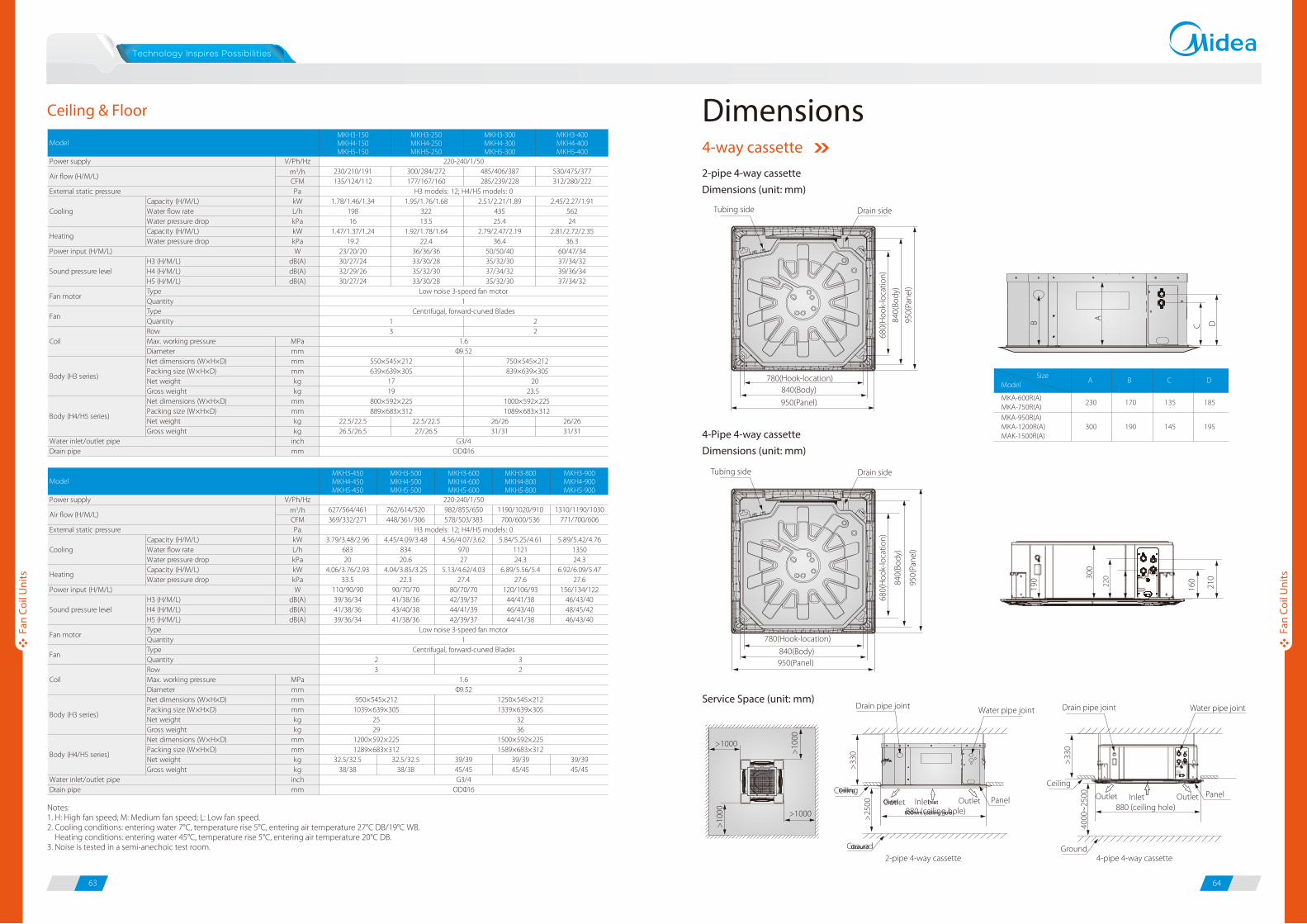
63 64
Ceiling & Floor
680(
Hoo
k-lo
catio
n)
840(
Body
)
950(
Pane
l)
780(Hook-location)
840(Body)950(Panel)
4-Pipe 4-way cassetteDimensions (unit: mm)
Service Space (unit: mm)
>1000
>1000
>10
00
>10
00
Ceiling
600mm (ceiling hole)
Ground
PanelInletOutlet Outlet880 (ceiling hole)
>25
00
Water pipe jointDrain pipe joint
Ceiling
880 (ceiling hole)
Ground
PanelInletOutlet Outlet
4000
~25
00
Water pipe jointDrain pipe joint
>33
0
Ceiling
Ground
InletOutlet
4-pipe 4-way cassette
300
190
220
160
210
680(
Hoo
k-lo
catio
n)
840(
Body
)
950(
Pane
l)
780(Hook-location)840(Body)
950(Panel)
Drain sideTubing side
2-pipe 4-way cassetteDimensions (unit: mm)
B A
C D
300 190 145 195
SizeModel
230 170 135 185
A B C D
MKA-950R(A)MKA-1200R(A)MAK-1500R(A)
MKA-600R(A)MKA-750R(A)
2-pipe 4-way cassette
Notes:1. H: High fan speed; M: Medium fan speed; L: Low fan speed.2. Cooling conditions: entering water 7°C, temperature rise 5°C, entering air temperature 27°C DB/19°C WB. Heating conditions: entering water 45°C, temperature rise 5°C, entering air temperature 20°C DB.3. Noise is tested in a semi-anechoic test room.
Dimensions4-way cassette
Fan
Coil
Uni
ts
Fan
Coil
Uni
ts
Tubing side Drain side
>33
0
MKH3-150MKH4-150MKH5-150
MKH3-250MKH4-250MKH5-250
MKH3-300MKH4-300MKH5-300
MKH3-400MKH4-400MKH5-400
V/Ph/Hzm3/h 230/210/191 300/284/272 485/406/387 530/475/377CFM 135/124/112 177/167/160 285/239/228 312/280/222Pa
Capacity (H/M/L) kW 1.78/1.46/1.34 1.95/1.76/1.68 2.51/2.21/1.89 2.45/2.27/1.91Water flow rate L/h 198 322 435 562Water pressure drop kPa 16 13.5 25.4 24Capacity (H/M/L) kW 1.47/1.37/1.24 1.92/1.78/1.64 2.79/2.47/2.19 2.81/2.72/2.35Water pressure drop kPa 19.2 22.4 36.4 36.3
W 23/20/20 36/36/36 50/50/40 60/47/34H3 (H/M/L) dB(A) 30/27/24 33/30/28 35/32/30 37/34/32H4 (H/M/L) dB(A) 32/29/26 35/32/30 37/34/32 39/36/34H5 (H/M/L) dB(A) 30/27/24 33/30/28 35/32/30 37/34/32
Max. working pressure MPaDiameter mmNet dimensions (W×H×D) mmPacking size (W×H×D) mmNet weight kgGross weight kgNet dimensions (W×H×D) mmPacking size (W×H×D) mmNet weight kg 22.5/22.5 22.5/22.5 26/26 26/26Gross weight kg 26.5/26.5 27/26.5 31/31 31/31
inchmm ODΦ16
1000×592×225
External static pressure H3 models: 12; H4/H5 models: 0
Sound pressure level
Water inlet/outlet pipe
839×639×30520
23.5
Body (H4/H5 series)
G3/4
750×545×212
220-240/1/50
Low noise 3-speed fan motor1
Centrifugal, forward-curved Blades
1.6
1 23 2
Type
FanTypeQuantity
Model
Power supply
Air flow (H/M/L)
Cooling
Power input (H/M/L)
Fan motor
1089×683×312
Quantity
Body (H3 series)
CoilRow
550×545×212639×639×305
1719
800×592×225889×683×312
Φ9.52
Drain pipe
Heating
MKH3-450MKH4-450MKH5-450
MKH3-500MKH4-500MKH5-500
MKH3-600MKH4-600MKH5-600
MKH3-800MKH4-800MKH5-800
MKH3-900MKH4-900MKH5-900
V/Ph/Hzm3/h 627/564/461 762/614/520 982/855/650 1190/1020/910 1310/1190/1030CFM 369/332/271 448/361/306 578/503/383 700/600/536 771/700/606Pa
Capacity (H/M/L) kW 3.79/3.48/2.96 4.45/4.09/3.48 4.56/4.07/3.62 5.84/5.25/4.61 5.89/5.42/4.76Water flow rate L/h 683 834 970 1121 1350Water pressure drop kPa 20 20.6 27 24.3 24.3Capacity (H/M/L) kW 4.06/3.76/2.93 4.04/3.85/3.25 5.13/4.62/4.03 6.89/5.56/5.4 6.92/6.09/5.47Water pressure drop kPa 33.5 22.3 27.4 27.6 27.6
W 110/90/90 90/70/70 80/70/70 120/106/93 156/134/122H3 (H/M/L) dB(A) 39/36/34 41/38/36 42/39/37 44/41/38 46/43/40H4 (H/M/L) dB(A) 41/38/36 43/40/38 44/41/39 46/43/40 48/45/42H5 (H/M/L) dB(A) 39/36/34 41/38/36 42/39/37 44/41/38 46/43/40
Max. working pressure MPaDiameter mmNet dimensions (W×H×D) mmPacking size (W×H×D) mmNet weight kgGross weight kgNet dimensions (W×H×D) mmPacking size (W×H×D) mmNet weight kg 32.5/32.5 32.5/32.5 39/39 39/39 39/39Gross weight kg 38/38 38/38 45/45 45/45 45/45
inchmm
1200×592×225
G3/4
External static pressure H3 models: 12; H4/H5 models: 0
Sound pressure level
Water inlet/outlet pipe
Body (H4/H5 series)
Φ9.52
1589×683×312
950×545×2121039×639×305
2529
1250×545×2121339×639×305
3236
1500×592×225
220-240/1/50
Low noise 3-speed fan motor1
Centrifugal, forward-curved Blades
1.6
23
32
Type
FanTypeQuantity
Model
Power supply
Air flow (H/M/L)
Cooling
Power input (H/M/L)
Fan motorQuantity
Body (H3 series)
CoilRow
ODΦ16Drain pipe
1289×683×312
Heating

82608
61
65 66
2-pipe compact 4-way cassetteDimensions (unit: mm)
Dimensions (unit: mm)
Dimensions (unit: mm)
Dimensions (unit: mm)
4-pipe compact 4-way cassetteDimensions (unit: mm)
30
50 630 570 110
30
30
30
530
655
Cei
ling
hole
wid
th
Pane
l wid
th
695
755
Panel length 1420
Ceiling hole length 1360
645 585 125Panel center65
1015
75
90
210
84
60
CA
D112
65
A 230
Model MKG-250-BMKG-300-BMKG-400-B
MKG-500-BMKG-600-BSize
B
114 D
A
B
D
C
732
915
663
290
892
1072
813
315
Model MKG-250MKG-300MKG-400
MKG-500MKG-600Size
A
B
D
C
915
290
670
725
1070
315
815
88525
42
48
66
290
69
C
290
425
169
MKC-300R(A)-B MKC-400R(A)-B MKC-600HRN4
Tubing sideDrain side
523(
Hoo
k-lo
catio
n)
575(
Body
)
647(
Pane
l)
261
190
124 21
3
261
H
190
124
213
110 15
7
545(Hook-location)
575(Body)
647(Panel)
Tubing sideDrain side
523(
Hoo
k-lo
catio
n)
575(
Body
)
647(
Pane
l)
545(Hook-location)
575(Body)
647(Panel)
Service Space (unit: mm)
Ground Ground2-pipe compact 4-way cassette
Height of the front panel
Type H (mm)
4-way cassette 45
Compact 4-way cassette 50
4-pipe compact 4-way cassette
>1000
>1000
>10
00
>10
00
Outlet600 (ceiling hole)
2300
~28
00
Water pipe joint Drain pipe joint
PanelCeiling
InletOutlet
>30
0
2300
~28
00
Water pipe joint Drain pipe joint
Ceiling
Outlet600 (ceiling hole)
PanelInletOutlet
>30
0
Compact 4-way cassette
1-way cassette
Wall mounted - S panel
Wall mounted - C panel
Fan
Coil
Uni
ts
Fan
Coil
Uni
ts
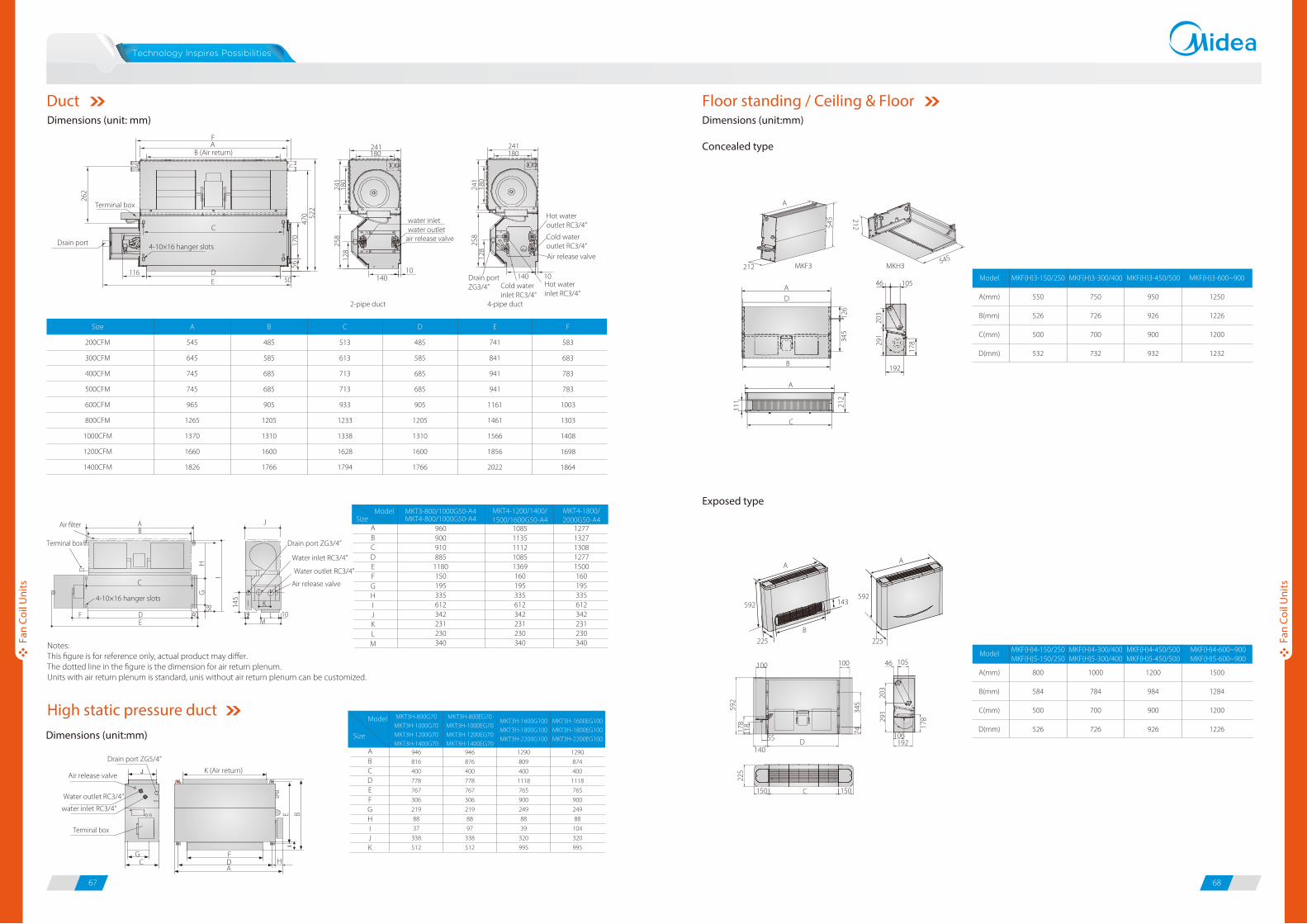
67 68
0
0
0
0
Model Size
AB
EDC
F
IHG
J
LK
M
900960
910885
1180150195335612342231230340
13271277
130812771500160195335612342231230340
MKT3-800/1000G50-A4
11351085
111210851369160195335612342231230340
MKT4-1200/1400/1500/1600G50-A4
MKT4-1800/2000G50-A4MKT4-800/1000G50-A4J
2-pipe duct 4-pipe duct
F241 241
water inletwater outlet
air release valve
Air release valve
1010140 140
180 180
262
56
58
145
E B
HG
I
170
470 52
2
241
241
180
180
258
258
545
126
345
203
291
212
203
345
592
118
178
225
178
74
291
111
178
128
128
AB (Air return)
K (Air return)
FDA
HG
C
Terminal box
4-10×16 hanger slots
4-10×16 hanger slots
C
DE
AB
40 19M
10L
K
EDF
Air filter
Terminal box
Terminal box
C
11650
Drain port
Water inlet RC3/4”
Water outlet RC3/4”
Notes:This figure is for reference only, actual product may differ.The dotted line in the figure is the dimension for air return plenum.Units with air return plenum is standard, unis without air return plenum can be customized.
Air release valve
Drain port ZG3/4”
water inlet RC3/4”
Water outlet RC3/4”
Air release valve
Drain port ZG5/4”
Size
200CFM
300CFM
400CFM
500CFM
600CFM
800CFM
1000CFM
1200CFM
1400CFM
A
545
645
745
745
965
1265
1370
1660
1826
B
485
585
685
685
905
1205
1310
1600
1766
C
513
613
713
713
933
1233
1338
1628
1794
D
485
585
685
685
905
1205
1310
1600
1766
E
741
841
941
941
1161
1461
1566
1856
2022
F
583
683
783
783
1003
1303
1408
1698
1864
Drain portZG3/4” Cold water
inlet RC3/4”Hot waterinlet RC3/4”
Cold wateroutlet RC3/4”
Hot wateroutlet RC3/4”
A
A105
MKF(H)3-150/250
550
526
500
532
MKF(H)3-300/400
750
726
700
732
MKF(H)3-450/500
950
926
900
932
MKF(H)3-600~900
1250
1226
1200
1232
Model
A(mm)
B(mm)
C(mm)
D(mm)
800
584
500
526
1000
784
700
726
1200
984
900
926
1500
1284
1200
1226
Model
A(mm)
B(mm)
C(mm)
D(mm)
192
46
D
B
A
AA
143
B
225
100 100 46 105
106192D
C 150150
140
55
225
592592
C
212545
212
MKF3 MKH3
Dimensions (unit: mm) Dimensions (unit:mm)
Concealed type
Exposed type
Dimensions (unit:mm)
Model
Size
AB
EDC
F
IHG
JK
816
946
400
778
767
306
219
88
37
338
512
MKT3H-800G70MKT3H-1000G70MKT3H-1200G70MKT3H-1400G70
876
946
400
778
767
306
219
88
97
338
512
MKT3H-800EG70MKT3H-1000EG70MKT3H-1200EG70MKT3H-1400EG70
MKT3H-1600G100MKT3H-1800G100MKT3H-2200G100
809
1290
400
1118
765
900
249
88
39
320
995
MKT3H-1600EG100MKT3H-1800EG100MKT3H-2200EG100
874
1290
400
1118
765
900
249
88
104
320
995
MKF(H)4-150/250MKF(H)5-150/250
MKF(H)4-300/400MKF(H)5-300/400
MKF(H)4-450/500MKF(H)5-450/500
MKF(H)4-600~900MKF(H)5-600~900
Duct
High static pressure duct
Floor standing / Ceiling & Floor
Fan
Coil
Uni
ts
Fan
Coil
Uni
ts

69 70
PC Board Control Kit for FCUWireless Remote ControllersAvailable for all non-PCB FCUs.
Flexibility installation: can be attached to the unit, mounted on a wall or hung under a ceiling.
External installation making maintenance more convenient.
Functions: three fan speeds control, Water pump control, Long-distance ON/OFF control, ALARM function,
electric heater control.
Operating status can be displayed by wired controller lamp indicator.
Centralized control function.
BMS control function through Modbus protocol.
Centralized control
BMS control function through Modbus protocol
X,Y,E
X,Y,E
Centralized controller
X,Y,E X,Y,E
P,Q,E
P,Q,E RS232 Pin hole BMSModbusModbus
USB port
P,Q,E P,Q,E
EPQ R+R-
E
FCUKZ-03 FCUKZ-04
Model
Applicable appliance
Power supply
Operation range
Temp. controlling precision
Net dimension
Packing size
Net weight
Gross weight
Room temp.
Inlet water temp.
W×H×D
W×H×D
V-Ph-Hz
oC
oC
oC
mm
mm
kg
kg
CE-FCUKZ-03
2-pipe FCUs
CE-FCUKZ-04
4-pipe FCUs
220~240-1-50/60
17-30
3-75
±1
296×66×212
410×115×262
1.4
2.5
Model Appearance
R05/BGE
R51/E
Function Descriptions Applicable FCUs
4-way Cassette (standard)
1-way Cassette (standard)
Compact 4-way cassette (standard)
Wall-mounted (standard)
Wired Controllers
Centralized Controllers
LCD display screen
Mode control
Fan speeds control
Time setting / Temp. setting / Swing setting
Model Appearance
KJRP-86A1-E
KJR-18B/E
Function Descriptions Applicable FCUs
Duct without electric heater (optional)
Duct without electric heater (optional)
KJR-21B/D
KJR-15B/E
Duct with electric heater (optional)
Floor standing / Ceiling & floor (optional)
LCD display screen
Mode control
Fan speeds control
Timer setting / Temp. setting
Mechanical thermostat
Mode control
Fan speeds control
Temp. setting
LCD display screen
Mode control / Fan speeds control
Electric heater control
Temp. setting
LCD display screen
Mode control
Fan speeds control
Temperature display in oF or oC
KJR-29B Cassette / Wall-mounted (optional)
Receiving remote signal
Mode control
Fan speeds control
Temp. setting
KJR-12B Cassette / wall-mounted (optional)
Swing function
Mode control
Fan speeds control
Temp. setting
Control Devices Accessories
Fan
Coil
Uni
ts
Fan
Coil
Uni
ts
Model Appearance
CCM03
CCM09
Function Descriptions Applicable FCUs
CCM30
Large LCD display screen
Max. of 64 FCUs can be controlled by a CCM03
Mode control / fan speed control
Time setting / temp. setting / swing setting
Weekly schedule function
Basic functions are same as CCM03
Touch-style keys
Basic functions are same as CCM03
All FCUs
(Compact 4-way cassette FCUs need adding NIM01 module,
non-PCB FCUs need adding PC board control kit)

Centralized wiring
Valve KitWorking Voltage: AC230±10%, 50/60Hz (24V can be customized).
Power Consumption: 4W
Nominal Pressure: 1.6MPa.
Applied Medium: Cold or hot water, 50% glycol water liquor.
Medium Temperature: 2 - 15°C (DDSTF-01), -20 - 1°C (DDSTF-04/05).
Environment Temperature: -5 - 50°C (DDSTF-01), 0 - 50°C (DDSTF-04/05).
Model
DDSTF-01
DDSTF-04
DDSTF-05
DN(mm)
20
15
20
Inner Screw Thead
3/4”
1/2”
3/4”
Applicable Appliance
2-pipe cassette/duct/floor standing, 4-pipe duct
4-pipe cassette (for hot water)
2-pipe ceiling & floor, 4-pipe cassette (for cold water)
DDSTF-01
DDSTF-04
DDSTF-05
71 72
Application of Central Control & BMS Control
Address setting
LED
XYE terminals
Side port connect to CN20 of FCU PCB
Network Module
Achieve centralized control through XYE connection;
Only available for FCU Cassette Series;
Address setting should be same as connecting FCU;
There LEDs display: operation indicator lamp, communication indicator lamp
and malfunction indicator lamp.
MD-NIM01Centralized controller
Centralized controller
BMS gatewayBMS
PC in LAN
BACnetModubusLonWorks
TCP/IP network
LAN
M-interface
Laptop Access
Pad Access
M-net
PC Access
PC
Cloud Servers
InternetRouter
Data converter CCM15
4th generation monitoring system
Up to 64 units
Up
to 1
6 sy
stem
s
Up to 64 units
PCB Kit NIM01
PCB Kit PCB Kit
Fan
Coil
Uni
ts
Fan
Coil
Uni
ts
Centralized controller
XYE XYE XYE XYE XYE
Up to 64 FCUs
CN20 on PCB CN20 on PCB CN20 on PCB CN20 on PCB CN20 on PCB
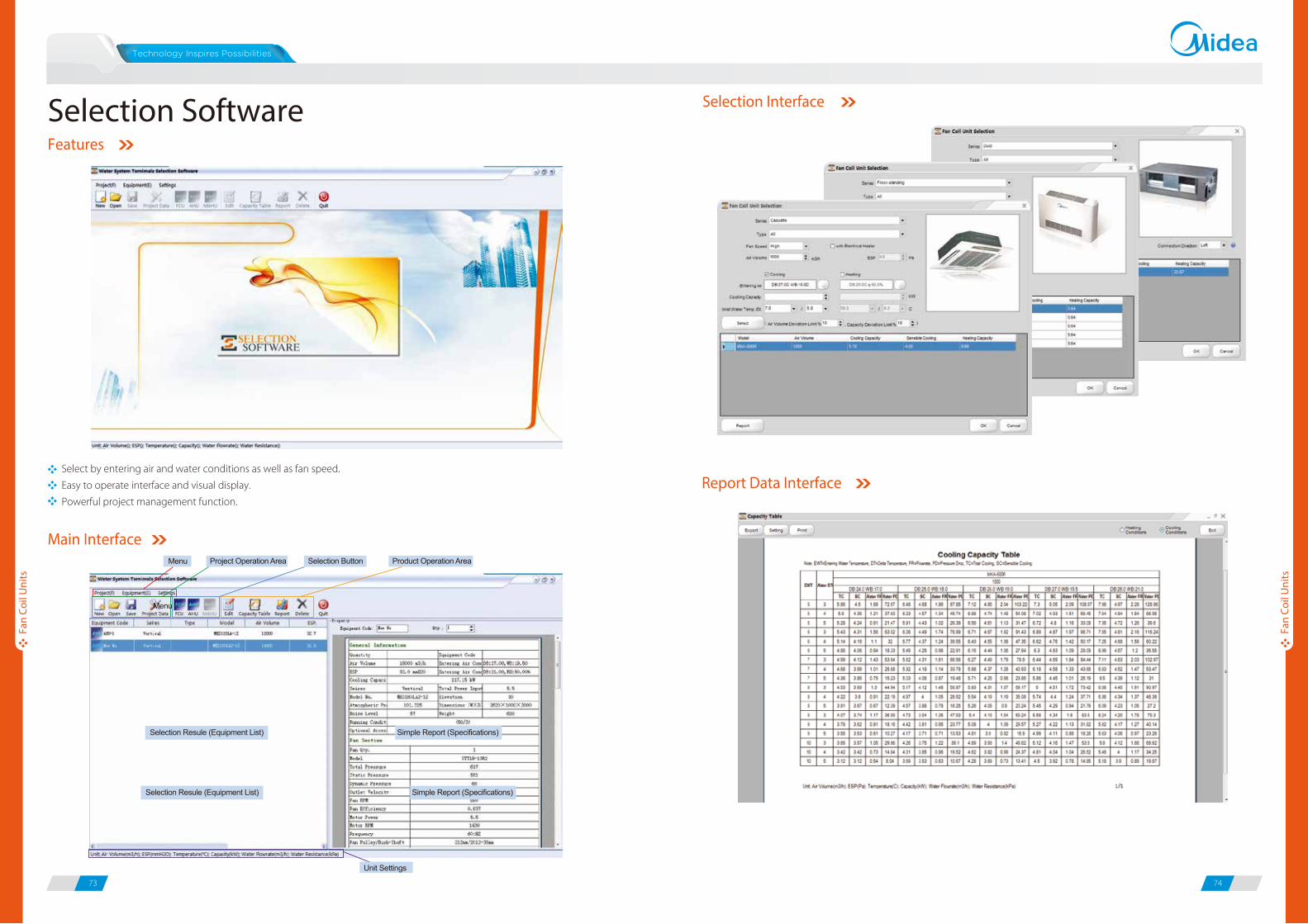
73 74
Select by entering air and water conditions as well as fan speed.
Easy to operate interface and visual display.
Powerful project management function.
Features
Main Interface
Selection Interface
Report Data Interface
Selection Software
Fan
Coil
Uni
ts
Fan
Coil
Uni
ts
![New Aqua Key Aqua Facts - Earth Observing System · 2017. 1. 26. · Earth Science Reference Handbook [ Missions: Aqua ] 73 Aqua Summary Aqua is a major international Earth Science](https://static.fdocuments.us/doc/165x107/604176e56ec9bf22204cde4b/new-aqua-key-aqua-facts-earth-observing-system-2017-1-26-earth-science-reference.jpg)