Comment on the Proposed Drilling Plan for LANL...
13
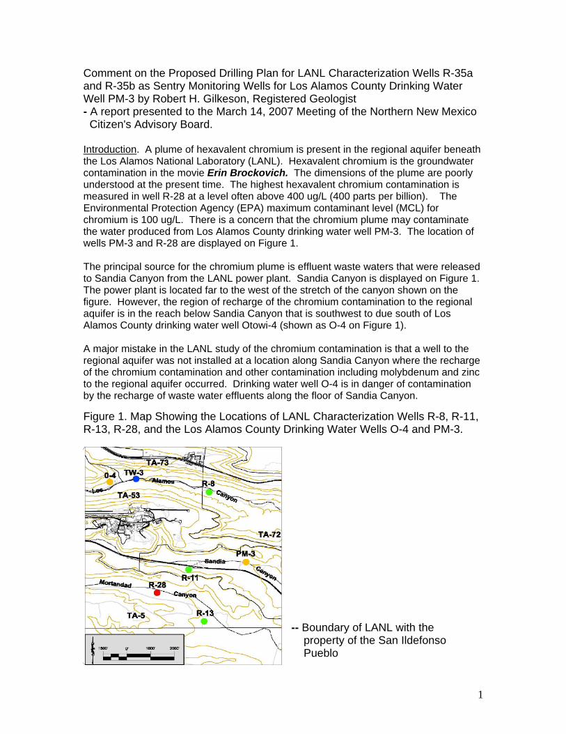
1 Comment on the Proposed Drilling Plan for LANL Characterization Wells R-35a and R-35b as Sentry Monitoring Wells for Los Alamos County Drinking Water Well PM-3 by Robert H. Gilkeson, Registered Geologist - A report presented to the March 14, 2007 Meeting of the Northern New Mexico Citizen's Advisory Board. Introduction . A plume of hexavalent chromium is present in the regional aquifer beneath the Los Alamos National Laboratory (LANL). Hexavalent chromium is the groundwater contamination in the movie Erin Brockovich. The dimensions of the plume are poorly understood at the present time. The highest hexavalent chromium contamination is measured in well R-28 at a level often above 400 ug/L (400 parts per billion). The Environmental Protection Agency (EPA) maximum contaminant level (MCL) for chromium is 100 ug/L. There is a concern that the chromium plume may contaminate the water produced from Los Alamos County drinking water well PM-3. The location of wells PM-3 and R-28 are displayed on Figure 1. The principal source for the chromium plume is effluent waste waters that were released to Sandia Canyon from the LANL power plant. Sandia Canyon is displayed on Figure 1. The power plant is located far to the west of the stretch of the canyon shown on the figure. However, the region of recharge of the chromium contamination to the regional aquifer is in the reach below Sandia Canyon that is southwest to due south of Los Alamos County drinking water well Otowi-4 (shown as O-4 on Figure 1). A major mistake in the LANL study of the chromium contamination is that a well to the regional aquifer was not installed at a location along Sandia Canyon where the recharge of the chromium contamination and other contamination including molybdenum and zinc to the regional aquifer occurred. Drinking water well O-4 is in danger of contamination by the recharge of waste water effluents along the floor of Sandia Canyon. Figure 1. Map Showing the Locations of LANL Characterization Wells R-8, R-11, R-13, R-28, and the Los Alamos County Drinking Water Wells O-4 and PM-3. -- Boundary of LANL with the property of the San Ildefonso Pueblo
Transcript of Comment on the Proposed Drilling Plan for LANL...
1
Comment on the Proposed Drilling Plan for LANL Characterization Wells R-35a and R-35b as Sentry Monitoring Wells for Los Alamos County Drinking Water Well PM-3 by Robert H. Gilkeson, Registered Geologist - A report presented to the March 14, 2007 Meeting of the Northern New Mexico Citizen's Advisory Board. Introduction. A plume of hexavalent chromium is present in the regional aquifer beneath the Los Alamos National Laboratory (LANL). Hexavalent chromium is the groundwater contamination in the movie Erin Brockovich. The dimensions of the plume are poorly understood at the present time. The highest hexavalent chromium contamination is measured in well R-28 at a level often above 400 ug/L (400 parts per billion). The Environmental Protection Agency (EPA) maximum contaminant level (MCL) for chromium is 100 ug/L. There is a concern that the chromium plume may contaminate the water produced from Los Alamos County drinking water well PM-3. The location of wells PM-3 and R-28 are displayed on Figure 1. The principal source for the chromium plume is effluent waste waters that were released to Sandia Canyon from the LANL power plant. Sandia Canyon is displayed on Figure 1. The power plant is located far to the west of the stretch of the canyon shown on the figure. However, the region of recharge of the chromium contamination to the regional aquifer is in the reach below Sandia Canyon that is southwest to due south of Los Alamos County drinking water well Otowi-4 (shown as O-4 on Figure 1). A major mistake in the LANL study of the chromium contamination is that a well to the regional aquifer was not installed at a location along Sandia Canyon where the recharge of the chromium contamination and other contamination including molybdenum and zinc to the regional aquifer occurred. Drinking water well O-4 is in danger of contamination by the recharge of waste water effluents along the floor of Sandia Canyon.
Figure 1. Map Showing the Locations of LANL Characterization Wells R-8, R-11, R-13, R-28, and the Los Alamos County Drinking Water Wells O-4 and PM-3.
-- Boundary of LANL with the property of the San Ildefonso Pueblo

2
As shown on Figure 1, the property of the San Ildefonso Pueblo is ¼-mile to the south of well R-28. LANL well R-13 does not establish the lateral dimensions of the hexavalent chromium plume because the top of the well screen is 125 feet below the water table, and below confining beds of clayey sediments. It is very probable that the chromium plume is present in the highly permeable aquifer strata that are present at a shallow depth below the water table at the location of well R-13. It is very probable that the chromium plume is contaminating the regional groundwater resource that is the property of the San Ildefonso Pueblo. It is also possible that the level of hexavalent chromium contamination is greater on the Pueblo property than is measured at well R-28. There is an immediate need to install a reliable monitoring well on the property of the San Ildefonso Pueblo at a location south of well R-28. LANL presentation to the March 14, 2007 meeting of the CAB on “the path forward for drilling reliable monitoring wells at LANL.” The LANL presentation includes two reports submitted to the CAB: Broxton, David, 2006. “A Brief History of Drilling for the Hydrogeologic Workplan at LANL,” – a Powerpoint presentation to the May 15, 2006 meeting of the National Academy of Sciences study committee on LANL groundwater protection practices. The meeting convened in Santa Fe, New Mexico. LANL, 2006. “Drilling Workplan for Regional Aquifer Wells R-35a and R-35b,” LANL report LA-UR-06-3964, June 2006. Comment on the Broxton Report. The Broxton report presents the position that the casing advance drilling method resulted in abandonment of drill casings in 8 of the boreholes for a total abandonment of 2,632 feet of casing. In the Broxton report, abandoned casing is listed in wells R-7, R-8, R-9, R-12, R-16, R-19, R-25, and R-31. In many reports and at many meetings, the staff of LANL, the Department of Energy (DOE), and the New Mexico Environment Department (NMED) have claimed that the casing advance drilling method is too risky and too costly, and therefore, it is necessary to drill the LANL monitoring wells with methods that invade the screened intervals with drilling fluids that have well known properties to mask the detection of many LANL contaminants, and especially the radionuclide contaminants produced by the manufacture and research on nuclear weapons. A PowerpointR presentation by LANL scientist Ardyth Simmons also makes the incorrect claim that the casing advance drilling method is too costly and too risky. The Simmons presentation materials were a handout at the January 17, 2007 EMSR meeting of the CAB. I provided the CAB with a report to document that the casing advance drilling method was not responsible for the abandoned drill casing in any of the wells – Comment by Robert H. Gilkeson on the LANL Groundwater Data Adequacy Project as presented by Ardyth Simmons on January 10, 2007 (LA-UR-06-2146, LA-UR-06-3516, and LA-UR-06-4825). An important example of the wrong claim that casing was abandoned because of seizure by the borehole wall is the 953 feet of casing abandoned in well R-9. The drill casing was not seized to the borehole wall. Instead, retracting the drill casing was pulling the

3
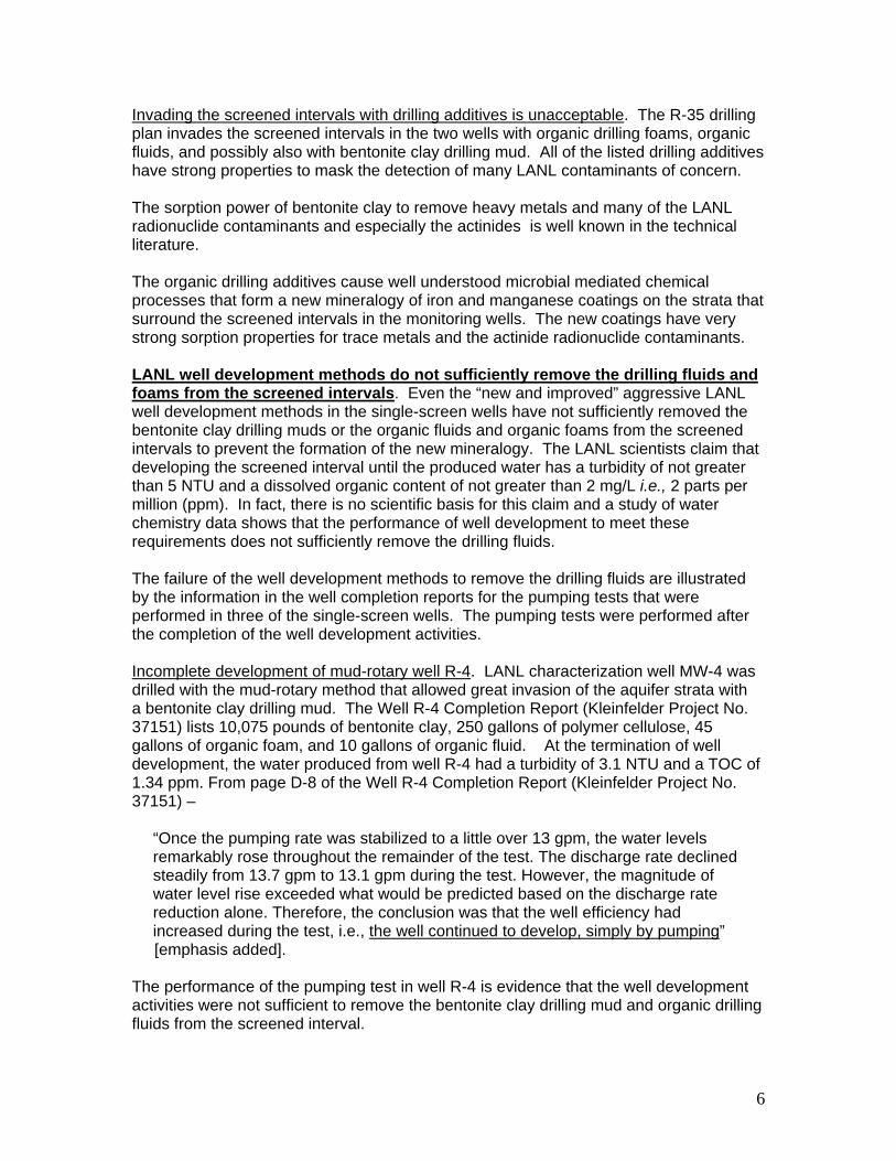
well out of the ground. The casing advance drilling method is not responsible for the mistakes made in constructing the well that caused the well to become “locked” to the drill casing. Furthermore, a review of the LANL Well R-31 Completion Report does not show that any drill casing was abandoned in this well as claimed in the Broxton and Simmons reports. A major factor that is responsible for the seizure of drill casing in the boreholes is the larger diameter of the threaded collars that attach together each 10-ft or 20-ft section of drill casing. The collars are displayed on Figure 2. The collars had a markedly larger diameter than the outside wall of the casing. The collars greatly increased the danger of the drill casing becoming seized in the boreholes, especially when too great a distance was drilled with one diameter of casing, and when adequate time was not spent with backreaming drilling to keep the borehole wall stable. Figure 2. The Large Threaded Connectors on the LANL Retractable Drill Casing Increased the Potential for the Casing to Become Seized in Boreholes.
The action of the larger diameter of the drill collars as catch points is illustrated by using the thumb and first finger on one hand to grasp before the knuckles of the fingers on the other hand. The larger size of the knuckles form catch points. The large collars were not necessary. Threaded collars with the same dimension as the drill casing are available and had adequate strength for the drilling activities. At wells R-9 and R-12, smooth outside wall drill casings were used with the dry air-rotary drilling method for drilling from land surface to a depth into the regional aquifer with the use of no organic drilling fluids, organic foam, or bentonite clay drilling muds. Also, at LANL, boreholes for characterization of the vadose zone were drilled with the dry air rotary casing advance method to depths of 700 feet with a single string of smooth walled drill casing. The drill casing was retracted during construction of multiple-port wells for sampling soil gas. The large collars slowed down the drilling speed and are one of the factors responsible for the abandonment of the drill casing in wells R-7, R-8, R-16, R-19, and R-25. The large collars greatly decreased the safe drilling depth for each discrete string of

4
telescoped casing. It also was necessary to spend more time with back-reaming drilling procedures to help stabilize the boreholes from collapsing and seizing the retractable drill casing. As a general rule, the larger size of the collars also required the use of organic drilling fluids or bentonite clay drilling muds to prevent strata in the borehole wall from seizing the casing. The drill casing was seized in the boreholes of wells R-19 and R-25 because of the attempt to drill the catch-point loaded drill casing without any drilling fluids other than air. The LANL scientists knew that the geologic strata beneath the Pajarito Plateau were unstable but did not take caution for the proper application of the casing advance drilling method with flush-threaded casing. Flush-threaded casings were only used for drilling the boreholes of the very first wells R-9 and R-12. All of the other wells with the exception of the recently installed well R-16r were drilled with the catch-point loaded drill casings. Well R16r was drilled in September, 2005 with three telescoped strings of smooth-walled drill casing [emphasis added]. Also, now the LANL scientists specify flush-threaded smooth outside wall drill casing for the casing advance drilling of the boreholes for the two new wells R-35a and R-35b. In LANL reports and at meetings, the casing advance drilling method is described as responsible for the high costs of wells R-8, R-9, R-12, R-16, and R-25. In all cases, there are other factors that are responsible for the high cost of the wells. The responsible factors are described in a case history report that I have provided to the CAB – “Case History Study of LANL Characterization Wells Installed in Boreholes Drilled With the Air Rotary Casing Advance Drilling Method” by Robert H. Gilkeson, M.S., Registered Geologist, February 20, 2007. For many of the LANL characterization wells, the high cost was because of the fluid-assisted open hole drilling methods that could not provide a stable borehole for installation of the characterization well. Often, the casing advance drilling method was used as a last resort to install a well in a borehole that open drilling methods could not prevent from collapse. Two examples are wells R-8 and R-16. The abandonment of drill casing in the two boreholes was because of drilling too great a distance in unstable strata with one diameter of drill casing that was loaded with “catch points” because of the large size of the threaded collars. Two analogies come to mind for the misplaced blame that is placed on the casing advance drilling method –
- Hammers should be banned because they often hit and bruise fingers.
- Cars should be banned because they cause accidents. Comment on the LANL Drilling Plan for Characterization Wells R-35a and R-35b. The two wells will be located approximately 500 feet to the west of the Los Alamos County drinking water well PM-3 to investigate the lateral and vertical extent of the chromium plume. In addition, the two wells will serve as long-term sentry monitoring wells to identify the travel of a large suite of LANL contaminants to the drinking water well. The wells will serve in the capacity of sentry wells for the next 50 to 100 years. The potential groundwater contaminants include many chemicals, the strongly sorbing actinide radionuclides plutonium, neptunium, and americium, and the moderately sorbing radionuclide contaminant strontium-90. There is an essential need to install the wells in a pristine environment clean of any organic or bentonite clay drilling additives. This is

5
because of the need to have accurate knowledge of the presence of ultra-tiny amounts of the radionuclide contaminants in the groundwater samples produced from the wells. The EPA drinking water standard (DWS) for strontium-90 is 8 picocuies per liter of water (8 pCi/L.). The tiny mass of strontium-90 that provides an activity level of 8 pCi/L is 60 parts per quintillion. Changes by three orders of magnitude each are marked in the sequence parts per million, parts per billion, parts per trillion, parts per quadrillion, and then parts per quintillion. One part per quintillion is one trillionth of a part per million. A visual representation is that 14 parts per quintillion would be the equivalent of about 14 drops of pollutant in 1 million standard 10,000 gallon railroad tank cars. Because of the new research on health, there is a concern to lower the current EPA DWS for the combined level of the actinide contaminants by two orders of magnitude from 15 pCi/L to 0.15 pCi/L. Accordingly, in a letter dated November 2, 2005 Governor Richardson recommended for EPA to consider lowering the drinking water standard for the actinides. Below is an excerpt from the Governor Richardson letter to EPA:
The IEER web-site for the report mentioned in the Richardson letter and for reports on the mobility of the radionuclides is www.ieer.org/ . The actinide radionuclides are also a danger to public health when present at ultra-trace levels in drinking water. Well PM-3 is displayed on Figure 1. The plan is to install well R-35b in aquifer strata with high permeability at a shallow depth near the regional water table. Well R-35a will be installed at a depth of approximately 300 ft below the water table in aquifer strata with high permeability that produce water to the upper part of the screened interval in drinking water well PM-3.
6
Invading the screened intervals with drilling additives is unacceptable. The R-35 drilling plan invades the screened intervals in the two wells with organic drilling foams, organic fluids, and possibly also with bentonite clay drilling mud. All of the listed drilling additives have strong properties to mask the detection of many LANL contaminants of concern. The sorption power of bentonite clay to remove heavy metals and many of the LANL radionuclide contaminants and especially the actinides is well known in the technical literature. The organic drilling additives cause well understood microbial mediated chemical processes that form a new mineralogy of iron and manganese coatings on the strata that surround the screened intervals in the monitoring wells. The new coatings have very strong sorption properties for trace metals and the actinide radionuclide contaminants. LANL well development methods do not sufficiently remove the drilling fluids and foams from the screened intervals. Even the “new and improved” aggressive LANL well development methods in the single-screen wells have not sufficiently removed the bentonite clay drilling muds or the organic fluids and organic foams from the screened intervals to prevent the formation of the new mineralogy. The LANL scientists claim that developing the screened interval until the produced water has a turbidity of not greater than 5 NTU and a dissolved organic content of not greater than 2 mg/L i.e., 2 parts per million (ppm). In fact, there is no scientific basis for this claim and a study of water chemistry data shows that the performance of well development to meet these requirements does not sufficiently remove the drilling fluids. The failure of the well development methods to remove the drilling fluids are illustrated by the information in the well completion reports for the pumping tests that were performed in three of the single-screen wells. The pumping tests were performed after the completion of the well development activities. Incomplete development of mud-rotary well R-4. LANL characterization well MW-4 was drilled with the mud-rotary method that allowed great invasion of the aquifer strata with a bentonite clay drilling mud. The Well R-4 Completion Report (Kleinfelder Project No. 37151) lists 10,075 pounds of bentonite clay, 250 gallons of polymer cellulose, 45 gallons of organic foam, and 10 gallons of organic fluid. At the termination of well development, the water produced from well R-4 had a turbidity of 3.1 NTU and a TOC of 1.34 ppm. From page D-8 of the Well R-4 Completion Report (Kleinfelder Project No. 37151) –
“Once the pumping rate was stabilized to a little over 13 gpm, the water levels remarkably rose throughout the remainder of the test. The discharge rate declined steadily from 13.7 gpm to 13.1 gpm during the test. However, the magnitude of water level rise exceeded what would be predicted based on the discharge rate reduction alone. Therefore, the conclusion was that the well efficiency had increased during the test, i.e., the well continued to develop, simply by pumping”
[emphasis added]. The performance of the pumping test in well R-4 is evidence that the well development activities were not sufficient to remove the bentonite clay drilling mud and organic drilling fluids from the screened interval.

7
Incomplete development did not remove organic foam in well R-16r. Well R-16r was drilled with a fluid-assisted air-rotary casing advance drilling method that allowed the organic drilling fluids QUIK-FOAMR and EZ-MUDR to invade the screened interval of the single-screen well. At the termination of well development, the water produced from well R-16r had a turbidity of 4.28 NTU and a TOC of 0.99 ppm. A pumping test to measure aquifer properties was performed in well R-16r after the well development activities were completed. Below is an excerpt from the pumping test report included as an appendix in the LANL Well R-16r Completion Report (Kleinfelder Project No. 49436, February 2006) –
“Test data were affected profoundly by air trapped or dissolved in the formation. During testing, the air was able to come out of solution and/or expand and contract in response to pumping and recovery. The air affected performance by clogging formation pores and entering the well and pump, resulting in very unusual data sets” [emphasis added].
The above excerpt from the pumping test reveals that the well development was unsuccessful in removing the drilling foam and the drilling air trapped within the foam . The drilling foam plugged the aquifer strata resulting in an unreasonably low and spurious permeability value measured by a pumping test. In addition, the new mineralogy formed by the organic drilling foam causes the well to produce unreliable water quality data for knowledge of the presence of the LANL contaminants. There is a need for additional development of well R-16r and performance of a new pumping test in well R-16r. After the redevelopment efforts, an extensive and expensive field test of the ability of the well to accurately detect LANL groundwater contamination is necessary. It may be necessary to replace well R-16r. Incomplete development did not remove organic foam in well R-34. Well R-34 is located along the predicted flow path of the chromium plume to the southwest of Figure 1 on the property of the San Ildefonso Pueblo. The open borehole for the single-screen well (23-ft long screen) was drilled with fluid-assisted air rotary drilling methods that invaded the strata surrounding the borehole with organic drilling foam that contained drill air. At the termination of well development, the water produced from well R-34 had a turbidity of 3.70 NTU and a TOC of 1.99 ppm. The pumping test in well R-34 did not provide reliable information on the permeability of the aquifer strata because of the out-gassing of the drill air and foam.
From the LANL well R-34 pumping test report:
- “The presence of air in the formation water interfered with pump operation, resulting in either erratic discharge rate fluctuations or no flow at all.”
- “Furthermore, the presence of the gas phase would be expected to significantly reduce the formation hydraulic conductivity.” The LANL report documented the problems that prevent the pumping test from providing reliable measurement of the aquifer permeability. Nevertheless, the LANL Synthesis Report published the obviously spurious permeability value of 3.5 ft/day.
The low permeability value in the Synthesis Report is also contradicted by the description of the coarse strata at the screened interval in Well R-34 and by the results of the Schlumberger borehole geophysics. Table 2-5 in the Synthesis Report describes
8
the aquifer strata at well R-34 as “fairly coarse gravels with some cobble beds”. Table 2-5 has a similar description of the aquifer strata at the nearby wells R-11 and R-28 where pumping tests measured permeability values of 116 and 149 ft/day, respectively. In addition, the Schlumberger geophysics logs are similar for wells R-11, R-28, and R-34. The geophysics data show the presence of a 64-ft thick section of aquifer strata immediately below the water table at the location of well R-34 that warrant a permeability of greater than 125 ft/day. The thick section of permeable strata may be contaminated with hexavalent chromium that is not monitored by the deep depth of the well screen. A conservative estimate is that the regional aquifer at the location of well R-34 has an ability to produce water from a single well at a rate of greater than 1,100 gallons per minute or 1.5 million gallons per day. The valuable water resource may be contaminated with chromium.
It is important to note that the Schlumberger Geophysics logs identify that the screened interval in well R-34 was not installed in the aquifer strata with highest permeability. In fact, the Schlumberger logs identify clay sediments to be present across the top 6 ft and in a thin zone in the middle of the screened interval. Greater than 30 % of the screened interval is surrounded by clay strata with low permeability. Open-hole drilling methods are unacceptable. The drilling history at LANL for the geologic setting of the R-35 wells has established that the open-hole drilling methods are too risky and too costly. The proposed plan for open-hole drilling of the two wells is unacceptable because of the danger of borehole collapse, the loss of the open-hole drilling equipment, and the need to drill a new borehole. Of course, a very important reason open-hole drilling methods are unacceptable is the invasion of the screened intervals with drilling fluids that mask the detection of contamination. .
LANL characterization well R-8. Well R-8 is one example of the failure of the attempt to drill an open borehole with the same open-hole methods proposed for the two R-35 wells. The location of Well R-8 north of drinking water well PM-3 is displayed on Figure 1.
The failure of the open-hole drilling methods at well R-8 is described in the well R-8 completion report.
“After surface casing was set, BH1 was drilled from 30 ft to 390 ft bgs using a 14.50-in. under-reaming down-hole hammer (UR-DTH) bit while advancing 13.375-in. drill casing. The 13.375-in. casing was landed in the Puye Formation at 390 ft. [Open borehole] drilling resumed with borehole advancement to a depth of 1022 ft bgs. The drillers decided to switch to casing-advance methods when they encountered flowing sands. Dynatec began to trip out the drill string to make the conversion to casing-advance with 11.75-in. drill casing. While pulling the assembly out of the borehole, the drillers experienced very tight borehole conditions in the interval between 680 to 750 ft bgs and could not work the drill-bit assembly beyond this interval. From October 26 to 30, 2001, Dynatec worked to free the drill assembly while continuing to repair the drill rig. On October 31, 2001, Dynatec retrieved all the drill pipe; however, the drillers had twisted off the drill-bit assembly and left the stabilizer, the air-exchange sub, and the bit in the borehole.”
A period of two months was spent in the unsuccessful attempt to recover the seized drilling equipment in the open borehole. The first borehole was plugged and abandoned.
9
LANL characterization well R-4. A second example of the failure of open borehole methods and loss of drilling equipment is the first borehole that was drilled for well R-4 with the same drilling methods proposed for open borehole drilling at the two R-35 wells. Well R-4 is located northwest of the two R-35 wells. Below are excerpts from the LANL Well R-4 Completion Report:
- “The following day the borehole was advanced to 270 ft bgs where the bit and DTH assembly became stuck due to the accumulation of approximately 47 ft of slough above the drill bit. WDC elected to trip in 2-in tremie pipe to 214 ft bgs, about 6 ft above the top of the slough and airlift the slough from above the drill bit to the surface. This strategy was successful and, once freed, the drill string was tripped out of the borehole.”
- “On August 30, 2003, WDC switched to a 12¼-in tricone drill bit and resumed drilling at 270 ft bgs using air-rotary drilling technique assisted with drilling fluids consisting of QUIK-FOAM®, EZ-MUD®, and potable water [for drilling an open borehole to a total depth of 845 ft bgs.”
- “WDC experienced difficulty tripping out the drill stem from 845 ft bgs and had to back-drill up to make progress. The drill stem could not be pulled past 710 ft bgs and operations ceased for the day. The following day, WDC tagged the top of slough and determined there was approximately 235 ft of slough above the drill bit preventing the drill stem from being tripped out.”
- “On the morning of September 6, 2003, after working until midnight trying to free the drill stem without success, the tremie pipe was tripped out of the borehole and it was discovered that the lower 120 ft of tremie pipe had sheared off. WDC attempted to view the lost tremie pipe with the down-hole video camera on September 6, 2003. On September 7, 2003, efforts to fish-out the lost tremie pipe sections resulted in the loss of an additional 60 ft of pipe. Subsequent efforts to pull the drill string were unsuccessful. On September 8, 2003, WDC, in agreement with the DOE and NMED project representatives, decided to break off the drill stem and plug and abandon the borehole.”
High-Risk of Open Hole Drilling Acknowledged in LANL R-35 Drilling Plan. In fact, the LANL R-35 drilling plan acknowledges the high risk for the open hole drilling. From pages 1 and 2 of the plan –
- “As the open borehole is advanced, caving of poorly consolidated geologic units such as the Totavi Lentil and Santa Fe Group deposits may result in unstable borehole conditions that could lead to loss of drilling equipment and possibly the borehole itself. If unstable conditions are detected, smooth-walled casing will be used to advance the borehole past the unstable zones. The use of a casing-advance system in conjunction with open-hole air rotary drilling may be sufficient to reach the target depth of the borehole. However, mud-rotary drilling may be used to complete the R-35a borehole in the event that insurmountable borehole stability problems are encountered while drilling with air-rotary and casing-advance systems.”
Mud-rotary drilling is unacceptable. LANL/DOE have made a serious mistake in the use of the mud-rotary drilling method for the installation of many of the LANL characterization wells. The drilling mud used with the mud-rotary method is a mixture of water with bentonite clay and organic additives including PAC-LR, a natural cellulosic polymer, and EZ-MudR, a liquid polymer emulsion containing partially hydrolyzed polyacrylamide/poly-acrylate (PHPA) copolymer.

10
The LANL scientists acknowledge the detrimental effect of the EZ-Mud that cause monitoring wells to produce unreliable water quality data. From page 2 of the R-35 drilling plan –
“Because of the potential impact on groundwater quality, its use [EZ-MudR] is limited to drilling situations where it can improve borehole stability or it is needed to control lubricity and fluid viscosity when drilling with bentonite or foam.”
Nevertheless, a review of the LANL reports shows that EZ-Mud was allowed to invade the screened intervals in practically all of the LANL characterization wells.
The mud-rotary drilling method fills the borehole with a column of drilling mud. Because of the great depth to the water table at the well R-35 location, the column of mud has a hydraulic force of greater than 350 pounds per square for invading the aquifer strata with the drilling mud. The powerful mud pump on the drill rig further increases the invasion force of the drilling mud. Recovery of most of the drilling mud by the well development activities is not possible because the invasion force is orders of magnitude greater than the limited extraction energy of the well development procedures.
The well R-35 drilling plan includes the use of the chemicals sodium acid pyrophosphate (SAPP) or AQUA-CLEAR PFD for well development with an incorrect claim that the chemicals remove the bentonite clay drilling mud. It is well understood in the monitoring well industry that the main effect of the chemical agents is to disaggregate the bentonite clay mudcake that has formed in the screened interval, and disperse the bentonite clay outward in the aquifer strata to a distance beyond recovery by the well development methods.
The combination of bentonite clay and organic additives establish a new mineralogy in the screened intervals with strong properties for masking the detection of many LANL contaminants, and especially, heavy metals, and the strongly sorbing actinide radionuclides.
Casing advance drilling method. Because of the high potential for failure in the attempt of drilling an open borehole, the required drilling method for the two R-35 wells is air-rotary casing advance with possibly four telescoped strings of drill casing. It is very important for each string of the drill casings to have smooth outer walls with flush-threaded connectors. The appropriate dimensions for the smooth outside wall of the three strings of casing are 13.75 inches, 11.75 inches, 9.625 inches, and 6.625 inches.
An important advantage of the air-rotary casing advance drilling method is that the drill casing prevents invasion of drilling fluids into the screened intervals.
Required dual rotary drill rig. The casing advance drilling must be performed with a dual rotary drill rig that meets the design specifications of the ForemostR Model DR-24 HD. The ForemostR Dual Rotary drill rigs feature two rotary drives; the lower rotary drive in the drill table is used to advance and retract the drill casing, and the upper rotary drive in the drill mast operates the downhole drilling equipment. The dual rotary drilling method is essential for efficiently drilling with casing advance. The slow performance of the casing advance drilling at LANL wells R-9 and R-12 was because the drilling was with an underpowered drill rig that only had rotation in the drill mast and that would only operate with drill casing sections not longer than 10 feet. The ForemostR Model DR-24 HD will drill with casing lengths of 20 feet.

11
Fluid-assisted drilling with casing advance. The casing advance drilling shall start at a shallow depth inside surface casing of 15-inch diameter that is cemented to an appropriate depth of approximately 30 to 50 feet. Water-based drilling fluids may be used to assist the casing advance drilling of the boreholes in the vadose zone. The use of water-based drilling fluids shall stop at an appropriate depth above the regional aquifer. This drilling strategy assumes that deliberate careful characterization of the presence of perched zones of saturation is not to be done. In the event that a thick, productive perched zone is discovered, the telescoped drill casings shall be used to seal off the zone.
Air-rotary drilling with casing advance in the regional aquifer. The only drilling method that is acceptable for drilling to the estimated depth of 300 feet into the regional aquifer is air-rotary casing advance. A careful log of drill cuttings, water production, and drill rig performance shall be kept during drilling.
Real-time analysis of water quality during drilling. Water samples shall be collected on an interval of every 5 to 10 feet of drilling and at changes in properties of the strata for “real-time” analysis at the field site for hexavalent chromium levels. EPA approved HachR kits provide accurate resolution of total and hexavalent chromium. The field measurements shall also include other appropriate analytes. Water samples shall also be submitted to a laboratory on a selected schedule for verification of the field measurements and for other analytes. The “real-time” profiling of water quality is of critical importance and is only possible if the only drilling fluid is air. Concerns of the EPA and the DOE/IG for the LANL practice of allowing drilling fluids to invade the screened intervals of monitoring wells. There are many recent LANL reports and independent reports by the Department of Energy Inspector General (DOE IG) and the Environmental Protection Agency (EPA) that prove the new network of LANL characterization wells and the old LANL test wells do not produce reliable data for the contamination of the regional aquifer with radionuclides and chemicals from LANL wastes.
DOE/LANL allowed organic drilling additives (both organic fluids and foams) to invade the screened intervals in all of the new characterization wells installed during the past ten years under the Hydrogeologic Workplan. In addition, many of the new wells were drilled with the mud-rotary method which invaded the screened intervals with bentonite clay drilling muds that also contained organic additives. The organic and bentonite clay drilling additives have well-known properties to mask the detection of most LANL chemical and radionuclide contaminants. The organic additives created a new mineralogy of iron precipitates, a slime which coats the strata that surround the screened interval masking the detection of contamination.
The failure of DOE/LANL to install a reliable network of monitoring wells is summarized in the notes recorded by a LANL scientist of a telephone conference call with the scientists from the EPA National Risk Management Research Laboratory in Ada, Oklahoma:
- “EPA also thought that iron minerals would not return to predrilling conditions in the foreseeable future.”
- “EPA further expressed the opinion that it would be difficult to determine when and whether the impacted screens would return to predrilling conditions. EPA expressed the opinion that LANL would never be able to get representative

12
samples from the impacted wells, but could only make choices and tradeoffs based on specific contaminants at various locations.”
At the request of the CAB, the EPA scientists wrote a report about the LANL well installation practices that allowed drilling fluids to invade the screened intervals of the characterization wells. Below are excerpts from the EPA report:
“Predictions of the time frames for the impacted intervals to return to natural conditions are uncertain. It is also likely that the inability to fully remove the additives which were used during drilling has reduced the hydraulic conductivity of many of the impacted screened zones.” “Due to the difficulty in assessing the damage that may be caused by the presence of residual drilling additives in the screened zone of a well, it is recommended that the need for continued use of additives within the screened interval of monitoring wells be reassessed.” “Strive to drill boreholes using no bentonite or organic additives within screened intervals. Additives may be used in intervals above the target monitoring zone if telescoping casing constructions are used and the hole is adequately cleaned before drilling the final footage within the interval to be screened. Targeting of monitoring intervals prior to drilling should be possible at locations where data from the existing characterization wells are available.”
The DOE IG wrote a report that described the failure of DOE/LANL to meet the requirements of the Resource Conservation and Recovery Act (RCRA) to install monitoring wells that produce reliable and representative water samples for the detection of LANL contaminants. From IG Report DOE/IG-0703, September 2005:
“However, LANL did not adhere to specific constraints established in the RCRA guidance when using muds and other drilling fluids, and, as a result, LANL could not assure that certain residual drilling fluids were fully removed; and muds and other drilling fluids that remained in certain wells after construction created a chemical environment that could mask the presence of radionuclide contamination and compromise the reliability of groundwater contamination data.”
The DOE IG Report also described the requirement for DOE/LANL to implement a surveillance groundwater monitoring program by December 31, 2005 under DOE Order 450.1. DOE/LANL are not in compliance with the DOE Order. Again, from the DOE IG Report:
The current requirements for a groundwater surveillance monitoring program are found in DOE O 450.1, “Environmental Protection Program,” which LANL has until December 31, 2005, to implement. As LANL works to meet this deadline, we believe that the Laboratory should, as the Hydrogeologic Workplan wells are converted to monitoring wells, ensure that monitoring data are reliable. We also believe that particular attention should be given to well development and purging methods, the quality of radionuclide data, and any qualifications on that data.”
DOE/LANL are not in compliance with the DOE Order as demonstrated by the conclusion presented in the LANL Well Screen Analysis Report (WSAR) published in

13
November 2005 that only approximately 50% of the new LANL characterization wells produce reliable and representative water samples. The WSAR was only a study of the effects of the drilling additives on the water quality data and did not address the many other factors that prevent the wells from meeting the requirements of monitoring wells. On September 18, 2006 , the New Mexico Environment Department (NMED) issued a Notice of Disapproval to LANL for the WSAR because of its failure to perform a thorough study. When all factors are considered, the number of LANL characterization wells that fail to produce representative and reliable water quality data is possibly greater than 90%. In the past few days, LANL has submitted the first revision of the WSAR to the NMED as required by the Notice of Disapproval. I will provide comments about the revised WSAR to a future meeting of the CAB. A rigorous sampling program for the Los Alamos County and Santa Fe drinking water wells is necessary because of the: 1). failure of DOE/LANL to install the required surveillance network of monitoring wells as required by RCRA and DOE Order 450.1, and 2). the groundwater contamination that is found in the 2006 draft LANL SWEIS and in the 1999 final LANL SWEIS. The rigorous sampling program requires collection of water samples on a quarterly schedule with analysis for a large suite of naturally occurring chemical and radionuclide constituents, chemical contaminants and radionuclide contaminants with the appropriate analytical methods for the highest possible precision in the measurements. Data from a reliable network of monitoring wells is the frontline of information about the sources of contamination from the LANL waste and impacts to the drinking water wells. After 10 years and approximately $150 million, LANL does not have the required network of wells for that knowledge. The continued obfuscation of data and failure to implement appropriate drilling methods does not help the process, nor protect drinking water supplies. The unreliable new network of characterization wells does not provide accurate information about the characteristics of the groundwater beneath LANL which is required by DOE Order 450.1, RCRA, New Mexico Water Quality Control Commission regulations, as well as the NMED/LANL Consent Order. Send Questions or Comments to Robert H. Gilkeson Registered Geologist RCRA Groundwater Specialist [email protected] phone 505-412-1930