Command valve wastegate control points the way...
16
Command valve wastegate control points the way forward HT i the latest news for holset turbochargers’ customers edition 3 Inside this edition: P3 Two’s company P5 The history of turbocharging in diesel engines P9 Alternative Bearing Systems
Transcript of Command valve wastegate control points the way...

Command valve wastegatecontrol points the way forward
HTithe latest news for holset turbochargers’ customers
edition 3
Inside this edition:P3 Two’s company
P5The history ofturbocharging indiesel engines
P9Alternative BearingSystems

Success for Holset growshand-in-hand with global useof turbochargers
HTi is the Holset magazine focussing on the world of heavy-duty turbocharging. It aims to bring you news on product and market developments.
HTi is produced using an environmentally approved printing process and is printed on fully recyclable and biodegradable paper.
Copyright © 2004 Holset Engineering Company Ltd. All rights reserved.Holset® and VGT™ are trademarks of Holset Engineering Company Ltd.
Sales of Holset turbochargers for mediumand heavy duty diesel engines havereached a record high in 2004. Improvedmarket conditions in the USA have playedtheir part together with the continuedsuccess of the company’s variablegeometry turbocharger (VGTTM) in a number of markets worldwide.
Increased demand for ‘clean’ and fuel-efficient high-performance diesels in Chinaand India has also boosted the demandfor Holset’s turbocharger range.
This continued growth in worldwidedemand has confirmed Holset’s strategy of continued growth, leading to anexpansion of turbocharger manufacturingcapacity in two key locations: Dewas, Indiaand Wuxi, China.
In March 2004, Holset moved its Chinaoperation to a new, purpose-built, world-class production facility in Wuxi servingboth domestic engine manufacturers andglobal customers as an export base.Additionally, in Dewas, Holset is alsoexpanding its manufacturing capacity tomeet the needs of the growing domesticand export markets in India.
These new manufacturing facilities, as wellas Holset’s longer-established plants inEurope and North America, serving whathas become a global customer base, aresupported by the company’s turbochargerdedicated technical centres; in the UK andChina. Their ever more vital andsophisticated research and developmentrole continues to be driven by a need fornew technology solutions to meet
progressively tougher exhaust emissionstandards, improved power density andgreater durability – typically matching thatof the engine itself. All this within ashorter product life cycle, as the pace ofengineering advance increases to maintainHolset’s technology leadership.
In the UK, Holset has recruited many new highly-qualified specialist engineers. This is to support the increased R&D and applications engineering challengesbrought by new emissions standards, ever higher output-per-litre powerdensities, whilst maintaining or evenimproving fuel efficiency.
In China, Holset’s technical centre hasbeen expanded to support its Asiancustomers with new turbochargerapplications, whilst undertakingperformance test and approval work for company operations in other parts of the world.
We look forward to strengthening ourrelationship with you and to meeting your current and future needs.
Paul Ibbotson, Managing Director
Page 1
Paul Ibbotson with ‘horsepower’

During 2004 Holset has expanded its operation in India, through Tata Holset, the company’s jointventure with the Tata Group of Companies, toincrease its turbocharger manufacturing andsupply capability in line with the needs of anumber of markets, including those of India’sdomestic diesel engine makers.
It comes as a further move in Holset’s strategy ofexpanding its worldwide manufacturing capacity,which last year saw the opening of a new worldclass facility at Wuxi in China to support thegrowing numbers of engine manufacturers nowestablished in China.
The new facility at Dewas in India is anexpansion of the established Tata Holset facility.The current and new buildings are joined byinterconnecting link corridors for the movementof materials and people. Space is available toexpand the new building in future years andfurther increase manufacturing capacity as theuse of turbocharged engines in road vehicles andfor off-highway diesel applications grows in thesub-continent. Fixed-geometry light to mediumrange turbochargers will remain the focus of theTata Holset product line, with an emphasis onmaintaining the high quality standards that bothOEM and end-user customers of the Dewas planthave come to expect.
Built to world class standards, based on a zero-defect manufacturing strategy, the plant isequipped with a fail-safe conveyor assembly line,replacing the previous method of turbochargerbench assembly. There are separate raw materialsand finished component stores.
The new Dewas plant is quite complex andunique to India. The pre-engineered structure ofthe main building is designed for earthquakeresistance and can be readily extended in thefuture. Maximum use is made in the new facility of natural light. New reception and meetingrooms project Holset’s corporate image. The open-plan office area is equipped withmodular furniture and centralised air conditioning,whilst great care has been taken to maintain a lush green environment around the plant.
The newly expanded site will help Tata Holsetmaintain the same global high standards in its manufacturing and customer serviceactivities as those for which other Holset facilitiesaround the world are already recognised.
Holset’s policy is to continue to expand itsworldwide manufacturing capacity to meet the growing worldwide demand for diesel engineturbochargers. India is a key market for Holsetand the company expects to build further on itsposition as market leader in the sub-continentand other parts of Asia, through long-terminvestment in Tata Holset.
India follows China in Holset’splant expansion programme Tata Holset increases capacity to meet growing market demands
Page 2
The newly expanded site willhelp Tata Holset maintain thesame global high standards in its manufacturing andcustomer service
Artist impression of new facility New facility in progress
Artist impression of the vision area
Artist impression of the reception

Greater demand is inevitably made on theturbocharger installation, in order to ‘squeeze moreair’ into the same cylinder space. Increased airdensity can only come from a higher turbochargerboost pressure.
Demand for higher boost pressures looks certain tocontinue as emission limits get tighter and tighter.With the implementation of Euro 4 and three yearslater, Euro 5 legislation, matched in North Americaby EPA ’07 and ’10, progressively higher pressureratios will be needed to enhance combustionefficiency and help to contain the peak combustiontemperatures that promote the formation of NOx(nitrogen oxide) emissions.
At the same time, the trend of engine downsizingbrings a further demand for power and torque perlitre of engine displacement.
Developing high pressure-ratio compressors with awide flow range has always been a key element ofHolset’s turbocharger development. It is a strategy,which under today’s market conditions assumeseven greater importance.
Increasing pressure ratios in single-stagecompressors invariably means the compressorwheel has to rotate at higher speeds and towithstand higher temperatures. Advances in design,manufacturing processes and materials technologyhave made significant improvements possible butthere is a practical limit beyond which pressureratio increases are no longer feasible oreconomically viable.
It is at this point that two-stage turbochargingbecomes a serious option. When two turbochargersare connected in series, the overall pressure ratio is the mathematical product of the two stages’individual pressure ratios. For example, if the twostages each deliver a 2.5:1 pressure ratio, then anoverall 6.25:1 ratio is possible, in theory at least. In practice, pressure losses in the system mean that the overall pressure ratio tends to besomewhat lower. Similarly, on the exhaust side, the turbine expansion ratio is split between the two units.
Truck and bus engine manufacturers are continually driven by competitive market pressures to improve performance and fuel economy from power units of given weight, size and swept volume. End-usercustomers demand more horsepower andhigher but flatter torque. Meanwhile, evertougher environmental legislation requiresprogressively lower noxious exhaustemissions.
Two’s Company
Page 3 Cummins QSK78 Courtesy of Cummins Inc.

Two-stage turbocharging is sometimes confused with so-called ‘sequential’turbocharging, where two different sized single-stage turbochargers are usedwith no multiplication of pressure ratios. Typically, the smaller turbocharger is‘active’ at low engine speeds and the second, larger, unit with its higher-inertiarotor, is brought into use by suitable control valves at higher engine speeds. In this way fixed-geometry turbochargers and narrow map compressors canmaximise boost across a wider engine speed range.
Typically, two-stage series turbocharging is applied to engines that need highpressure ratios in order to cope with ‘thin’ air at high altitude, without losingpower. For example, Cummins’ big 78 litre QSK78 industrial V18 diesel, fitted with HX60 and HX83 Holset turbochargers, has an impressive 6.7:1pressure ratio at 12,000ft (3,600m) altitude, where it can still develop its full3,500hp (2,600kW) power rating. Inevitably, on such engines, the air handlingsystem accounts for a large part of the total installation’s bulk. In road vehicle applications packaging of two-stage systems remains a challenge for manufacturers.
Selecting the best high and low pressure turbocharger sizes for a two-stageinstallation is clearly critical, deriving from the engine performance required and the application. In an industrial engine the turbochargers are often sized so that an equal pressure-ratio split is achieved at rated power.
However, in automotive engine applications where good low speedperformance with high torque is required the high-pressure turbocharger ismuch smaller, matched to low engine speed, where it is ideally sized forgiving good boost pressure and transient response. In this region two stageoperation is achieved with high overall pressure ratios.
A high-pressure turbine bypass is used to regulate control system pressures on the exhaust side. The bypass, opens as mass flow increases, in line withengine speed. Depending on how much bypass flow is allowed, the systemeither remains in two-stage configuration or, at higher engine speeds,effectively reverts to single-stage operation, with almost no contribution from the high-pressure turbocharger.
On the intake side, a bypass around the high-pressure compressor may also be needed. Use of such a feature is called modulated or switched two-stageoperation and can offer optimised turbocharging across a wider range ofengine speeds than the more basic two-stage system.
High boost pressures are inevitably and unfortunately accompanied by highboost temperatures. Once they exceed about 230oC, then aluminiumturbocharger components are liable to be structurally weakened. Specialintercooling, using an additional heat-exchanger type air cooler between thecompressor stages, therefore becomes necessary to prevent the high pressureturbo’s compressor from overheating. The only feasible alternative is foraluminium to be replaced with a more thermally resistant and expensivematerial in the temperature vulnerable compressor.
How does two-stage turbocharging fit in with other emission control strategies,notably cooled exhaust gas recirculation (EGR)? High EGR rates by definition require high turbo boost pressures for which two-stage systems are ideally suited. The two-stage concept also has its place onengines designed for use with filter or catalytic aftertreatment systems, whereback pressure issues can arise, such that the high overall efficiency of a two-stage system enables the best possible engine performance to be obtained.
Two-stage turbocharging is not just technology for the future though. Whether it be a car, truck or an industrial application, two-stage is here today!
HPturbinebypass
HPcompressorbypass
LPturbine
LPcompressor
Aft
erco
oler
Exhaust Intake
HP turbine HP compressor
LP turbine LP compressor
Aft
erco
oler
Exhaust IntakeTwo-Stage Turbocharging
ModulatedTwo-StageTurbocharging
Page 4
Two-stage turbocharging can be applied toengines that need high pressure ratios, forexample, 6.7:1 at 12,000ft (3,600m) altitude

At the end of the 19th Century huge progress had been made inthe development of machines, particularly in steam-poweredprime movers and in engineers’ understanding of the processesat work. Otto had demonstrated the four-stroke spark-ignitionengine. Akroyd Stuart and other pioneers in Britain and elsewherewere working on the principle of compression ignition, oftenusing additional heating sources outside the engine cylinder.
However it was Rudolf Diesel in Germany who is generallycredited with the design in 1893 of a practical engine in whichcombustion is initiated entirely by the heat generated duringcompression of the fuel-air mixture.
Surprisingly, it was barely ten years later that the Swiss engineerAlfred Büchi started thinking about pressure charging thecompression-ignition engine. His proposed system incorporatedall the essential elements of the modern turbocharged engine.Power output and operating efficiency was enhanced by anexhaust gas turbine driven intake air compressor.
Dr. Büchi graduated from the Swiss Federal Institute ofTechnology in Zurich in 1903 and subsequently worked withdiesel engine manufacturers in Belgium and Switzerland where his ideas came to fruition.
Fig 1 shows the patent Büchi obtained in 1911. His turbochargerconsisted of a multi-stage axial-flow compressor, complete with a simple intercooler, driven by a multi-stage axial-flow turbine on the same shaft, rotated by the kinetic energy of the exhaustgases leaving the reciprocating engine.
Acceptance of his innovative ideas were slow and he had tomake many detailed experiments to convince others of thebenefits of the system. Eventually Dr. Büchi succeeded inconvincing a German engine manufacturer to put his ideas intoproduction and in 1925 MAN began making the first ever engineswith Buchi turbochargers for marine applications.
The History of Turbocharging in Diesel EnginesThe evolution of the turbocharger has been fundamental to the development of the dieselengine. It has made possible the immense advances in performance, fuel economy andemissions reduction we have seen in all diesel power applications, particularly over the past 40 years- but where did the idea come from and how was it developed into today’s turbocharger?
Other experimenters were working aroundthe same time with boost-charged spark-ignition engines. Professor Rateau inFrance and Dr Sanford Moss in the USAhad experimented with turbochargedaircraft engines, while in Britain, MajorFrank Halford designed and built anexperimental 1.5 litre racing car engine in1923 – one of the earliest turbochargedautomotive engines (Fig 2).
Halford had been involved with aircraftengine design and manufacture for some10 years and would have been well awareof current developments. His enginefeatured a neatly installed radialcompressor. Its air inlet was drawnthrough the centre of the engine, driven by a close coupled axial flow turbine. The installation included an air-to-airintercooler below the engine sump.Halford went on to become a successfulreciprocating engine and gas turbinedesigner for the Napier and deHavillandcompanies.
Meanwhile, Dr Büchi realised that constantpressure turbine inlet conditions impairedcylinder scavenging at all engine speedsand loads. This shortcoming wouldhamper the application of turbochargingto high speed automotive engines. He carried out experiments that led to anunderstanding of ‘pulse charging’, usingsmall volume exhaust manifolds andturbines with a restricted throat area. It was a technique that preserved a highenergy, high pressure pulse when theexhaust valve first opened, but deliveredlow manifold pressures later in theexhaust stroke to promote cylinderscavenging.
Based on these principles, Saurer, theSwiss engine manufacturer went intoproduction in 1938 with what is probablythe first turbocharged heavy-duty roadvehicle diesel engine, shown in Fig 3.
In 1951, The Napier Company produced asomewhat complex turbocharged andturbocompounded diesel engine foraircraft use (Fig 4).
The Nomad was intended to be a low fuel consumption engine for freight-carrying aircraft. It was a flat 12 cylindertwo stroke diesel, whose turbochargercompressor and turbine were derived from a Napier gas turbine engine. The common turbine to compressor shaftwas driven from the engine crankshaft via a variable-speed gearbox. Thus theengine could drive the compressor ifrequired, but when excess turbine powerwas available, the system became aturbocompound engine. This enginedeveloped 3,250hp at an altitude of11,000ft (3,350m).
Dr. Alfred Büchi
Page 5
Saurer went intoproduction in 1938with what is probablythe first turbochargedheavy-duty roadvehicle diesel engine

Some flight development wasundertaken, but unfortunately thecomplexity of the engine compared withthe relatively simple gas turbine beingdeveloped at around the same time puta halt to the project.
From the 1950’s onwards, most heavy-duty truck and bus engine manufacturersexperimented with turbocharging andmany put such power units intoproduction. The turbochargers in theseearly automotive engines were relativelybulky, derived from larger industrialengine turbocharger designs. It was thedesign for a lightweight automotiveturbocharger from the SchwitzerCompany in 1957, which led to licencesbeing taken out by Holset for aturbocharger with a simple but robustbearing system that forms the basis ofthe modern automotive turbocharger. Fig 5 shows the Holset 3LD turbochargerof 1973.
Since these early days, Holset hasdeveloped its own turbochargertechnology leading to the H range, HX range and more recently, HE rangeproducts.
Turbocharging is now practically universalon all automotive diesel engines anddevelopments continue apace.Turbocompounding proposed by
Dr. Büchi in the 1930’s, has beenpursued by a number of truck enginemakers in the search for improvedthermal efficiency and fuel consumption.In 1991, Scania in Sweden put the firstexample into series production, an 11litre in-line six cylinder engine utilising aHolset designed power turbine able toharness much of the energy remaining inthe exhaust gases downstream of themain engine turbocharger, to augmentthe mechanical power delivered throughthe crankshaft. The crucial on-highwaypower and torque requirements of avariable-speed engine, where hightorque-rise and/or a very wide speedrange are key attributes, has led to thesuccessful development of wastegatedand subsequently variable-geometryturbochargers. The introduction in 1998of the Iveco Cursor range of 8, 10 and 13litre truck diesels in 1998 featuringHolset variable-geometry turbochargers(VGTsTM) became the first such heavy-dutyvolume production application.
For the future, the now ubiquitousturbocharger is certain to remain a vitalcomponent of all low-emissions diesels.Further exciting and innovativedevelopments are sure to take what is afundamentally simple concept into itssecond century, largely thanks to theremarkable vision and determination ofDr. Alfred Büchi.
Figure 2 Halford Engine
(1923) courtesy of
Douglas R. Taylor
Figure 4Napier Nomad Aircraft Engine
courtesy of Rolls Royce Heritage Trust
Figure 5Holset 3LD 1973
Turbocharger
Figure 3Saurer Engine
(1938)courtesy of Iveco
Figure 1Buchi 1911
patent
Page 6
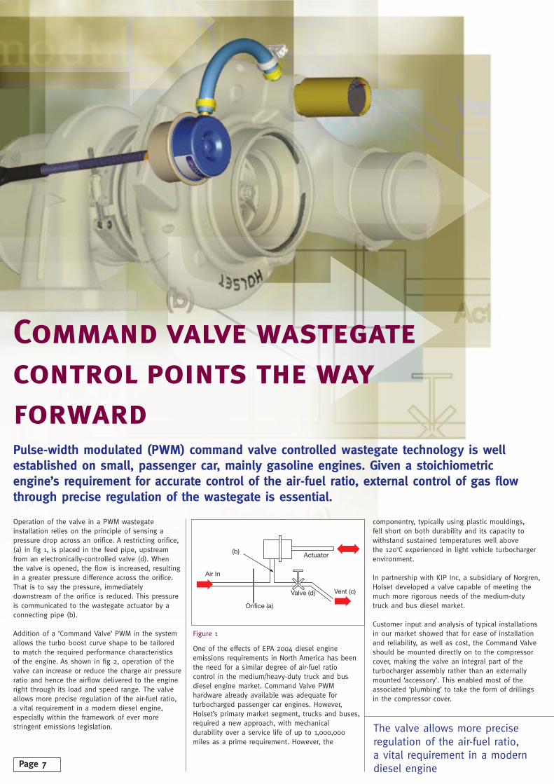
Command valve wastegatecontrol points the wayforwardPulse-width modulated (PWM) command valve controlled wastegate technology is wellestablished on small, passenger car, mainly gasoline engines. Given a stoichiometricengine’s requirement for accurate control of the air-fuel ratio, external control of gas flowthrough precise regulation of the wastegate is essential.
Operation of the valve in a PWM wastegateinstallation relies on the principle of sensing apressure drop across an orifice. A restricting orifice,(a) in fig 1, is placed in the feed pipe, upstreamfrom an electronically-controlled valve (d). Whenthe valve is opened, the flow is increased, resultingin a greater pressure difference across the orifice.That is to say the pressure, immediatelydownstream of the orifice is reduced. This pressureis communicated to the wastegate actuator by aconnecting pipe (b).
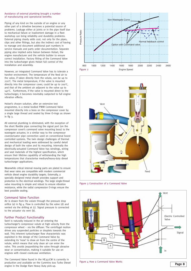
Addition of a ‘Command Valve’ PWM in the systemallows the turbo boost curve shape to be tailoredto match the required performance characteristics of the engine. As shown in fig 2, operation of thevalve can increase or reduce the charge air pressureratio and hence the airflow delivered to the engine right through its load and speed range. The valveallows more precise regulation of the air-fuel ratio,a vital requirement in a modern diesel engine,especially within the framework of ever morestringent emissions legislation.
Figure 1
One of the effects of EPA 2004 diesel engineemissions requirements in North America has beenthe need for a similar degree of air-fuel ratiocontrol in the medium/heavy-duty truck and busdiesel engine market. Command Valve PWMhardware already available was adequate forturbocharged passenger car engines. However,Holset’s primary market segment, trucks and buses,required a new approach, with mechanicaldurability over a service life of up to 1,000,000miles as a prime requirement. However, the
componentry, typically using plastic mouldings, fell short on both durability and its capacity towithstand sustained temperatures well above the 120oC experienced in light vehicle turbochargerenvironment.
In partnership with KIP Inc, a subsidiary of Norgren,Holset developed a valve capable of meeting themuch more rigorous needs of the medium-dutytruck and bus diesel market.
Customer input and analysis of typical installationsin our market showed that for ease of installationand reliability, as well as cost, the Command Valveshould be mounted directly on to the compressorcover, making the valve an integral part of theturbocharger assembly rather than an externallymounted ‘accessory’. This enabled most of theassociated ‘plumbing’ to take the form of drillingsin the compressor cover.
Orifice (a)
Actuator
Valve (d)
Air In
Vent (c)
(b)
Page 7
The valve allows more preciseregulation of the air-fuel ratio, a vital requirement in a moderndiesel engine
Avoidance of external plumbing brought a number of manufacturing and operational benefits:
Piping of any kind on the outside of an engine or anyother part of a driveline becomes a potential source ofproblems. Leakage either at joints or in the pipe itself dueto mechanical failure or inadvertent damage in a fleetworkshop can bring reliability and durability problems.External piping clearly adds cost, not only for the pipes,clips and other fittings, but also the indirect cost of havingto manage and document additional part numbers inservice manuals and parts order documentation. Separatepiping also implied extra liaison between Holset, theengine manufacturer and the vehicle builder to ensurecorrect installation. Factory fitting of the Command Valveinto the turbocharger gives Holset full control of theinstallation and assembly.
However, an integrated Command Valve has to tolerate aharsher environment. The temperature of the feed air tothe valve, if taken directly from the volute, can be up to220oC. The metal temperature, if the valve is mounteddirectly into the compressor cover, could be up to 200oC,and that of the ambient air adjacent to the valve up to140oC. Furthermore, if the valve is mounted direct to theturbocharger, it becomes inevitably subjected to full enginevibration effects.
Holset’s chosen solution, after an extensive testprogramme, is a metal bodied PWM Command Valvemounted directly into a boss on the compressor cover bya single large thread and sealed by three O-rings as shownin fig 3.
All external plumbing is eliminated, with the exception ofthe short flexible pipe connecting the signal port (on thecompressor cover’s command valve mounting boss) to thewastegate actuator, in a similar way to the compressorcover/actuator pipe connection used on conventional boostcontrolled systems. The twin design challenges of thermaland mechanical loading were addressed by careful detaildesign of both the valve and its mounting. Internally theelectrically-actuated Command Valve has windings, wiringand seat materials of the highest specification, whichensure their lifetime capability of withstanding the hightemperatures that characterise medium/heavy-duty dieselturbocharger applications.
Meanwhile critical internal moving parts are plated to ensurethat wear rates are compatible with modern commercialvehicle diesel engine durability targets. Externally, aspecially designed metal sheath provides support andprotection to the electrical windings. The large single-threadvalve mounting is simple and robust to ensure vibrationresistance, while the radial compression O-rings ensure thebest possible sealing.
Command Valve FunctionAir is drawn from the volute through the pressure droporifice (a) in fig 4. Flow is controlled by the valve (d) andvented via the drilling at (c). Signal pressure is connectedto the actuator via vent (b).
Further Product FunctionalitySwirl is naturally induced in the air entering theturbocharger’s compressor volute at high velocity from thecompressor wheel – via the diffuser. The centrifugal motiondrives any suspended particles or droplets towards thewall. This inherent turbocharger flow characteristic wasexploited in the design of the Command Valve byextending its ‘nose’ to draw air from the centre of thevolute, which means that only clean air can enter thevalve. This avoids jeopardising the valve through abrasivewear or contamination, making it suitable for use onengines with closed crankcase ventilation.
The Command Valve found in the HE351CW is currently inproduction and available on the Cummins 600 Turbo Dieselengine in the Dodge Ram Heavy Duty pick-up.
800 1000 1200 1400 1600 1800 2000 2200 2400 2600
Engine Speed
Normal feedback controlOption with Command valve
Non Wastegate Curve
Pre
ssur
e R
atio
Figure 4 How a Command Valve Works
Figure 3 Construction of a Command Valve
Figure 2
Page 8
Vent
In
Signal
Vent
D
C
B
A
Electric ControlledValve
Feed

At a time when any improvement in overall turbocharger efficiency can contribute critically to an engine’s ability to meet more stringentemission limits and performance targets, even modest percentagereductions in viscous bearing drag become technically attractive.
There are numerous emerging bearing system technologies, which at thecost of extensive development programmes, are poised to one day takeover from the typical hydrodynamic floating ring bearing used in today’smass market automotive turbochargers. Together with the axial thrustbearing, it has remained an intrinsic feature of Holset’s turbochargerrange since the 1950’s.
To describe the floating ring bearing as simply ‘a metal ring of someaxial length with radial holes’ is reasonably accurate, but tends totrivialise the complexity of the design. The main purpose of the floatingring bearing (see fig 1) is to create an inner and outer oil film, so thatthe shaft journal surface is constrained radially within the bearing, whichin turn is constrained radially by the housing. The floating ring bearing isdesigned to rotate at a fraction of rotor speed, which allows the rotorsystem to remain stable at high rotational speeds that would normallylead to instability in a plain journal bearing.
In contrast the axial thrust bearing (fig 2) is a relatively simple devicethat develops a hydrodynamic load due to the ‘wedge’ created by thegeometry of the tapered pads and the load carrying surface of the thrustcollar and oil slinger. Oil is dragged into the wedge under the influenceof viscous forces and because the oil is incompressible, pressure buildsup and hence the load is generated.
Why do we want to change floating ring bearings andaxial thrust bearings?Today’s floating ring bearings and axial thrust bearings are very costeffective to produce. Dimensional tolerances are easily controlled, givenmodern manufacturing methods and they deliver an acceptableperformance for the present generation of diesel engines. Also, theyprovide good shaft motion control with proven reliability and durability.However, tomorrow’s high performance, low emission engines are almostcertain to demand higher turbo efficiencies. Meanwhile the advent of aquite new bearing technology will offer the opportunity to addresssecondary issues like oil leakage, blowby and noise generation from outof balance and sub-synchronous vibrations that beset some currentturbo installations.
It is an unavoidable fact of life that viscous drag in the bearings of a turbocharger prevents a significant proportion of the power developed by the turbine from being ‘translated’ into worthwhile output from the compressor. At low turbo speeds this effect is more pronounced, contributing to turbo lag.
Alternative Bearing Systems
Figure 1 Floating Ring Bearing
Figure 2 Axial Thrust Bearing
Figure 3 Air Foil Bearing
Page 9
Oil Supply
Shaft
Outer Film Bearing Housing
Inner Film
FRB
Collarmotion
Hydrodynamicpressure
Oil dragged in under viscous drag
Oil squeezedout wedge sides
Taper wedgedesign
Bump foil Bearing Sleeve
JournalTop foil
Dimensional tolerances are easily controlled, given modern manufacturing methods and they deliver an acceptable performance for the present generation of diesel engines

Where do we go from here – what arethe options?Bearing systems offering potential advantages over current designs include:
a) Hydrodynamic air bearings use air as the‘lubricant’ separating the adjacent bearing surfaces.Among the technology challenges are the needs, at considerable extra cost, for very small clearancesand the probable use of ceramic in place of metalmaterials. However, they have been shownconclusively to deliver the key benefit of very lowparasitic drag.
b) Airfoil bearings (fig 3) consist of a compliantspring-mounted metal foil that wraps around theshaft surface. Parasitic losses are commendably low,but initial start-up friction and associated wear posea significant technical challenge given the extendeddurability demands now made of turbochargers.
c) Rolling-element designs typically feature deep-groove ball bearings with ceramic balls and ceramicor metal races. Parasitic drag would be significantlyreduced, but rolling-element bearings are unlikely tomatch current floating ring bearing durabilitystandards.
d) Hydrostatic bearings require a high pressure gasto maintain the clearance between two surfaces.Durability is expected to be excellent, parasiticlosses are low and small aerodynamic clearances canbe maintained.
e) Active magnetic bearings (fig 4) use anelectronically-controlled series of magnetic coils ateach bearing station to centre the shaft precisely.This offers the prospect of very low vibrations, with correspondingly low parasitic drag.
Spoilt for choice?There is no single factor that makes any of theabove options an obvious choice. Holset hasaccordingly applied a technique known as QualityFunction Deployment (QFD). It involves a detailedevaluation of the design features of today’s floatingring bearing and axial thrust bearing turbobearings, allocating to each a plus or minus valuedepending on its respective degree of advantage or disadvantage to the finished product. It wasnecessary to group those factors into variouscategories, according to their different levels ofimportance attributed by particular OEM customers.
Bearing durability and reduced noise continue todominate many OEM customers’ expectations,which often correlate with numbers of warrantyclaims. Within this category, specific issues include:
Sub-synchronous noise: vibration attributable tofluid (oil) film instabilities. Once per rev noise (or synchronous vibrations):due to imbalance. Degree of imbalance tolerance: related to availablemachinery and manufacturing process capability. Emergency failsafe: consequences of mechanical failure. Cooling: efficiency of oil’s cooling medium role. Dirt tolerance: critical to bearing durability. Thermal effects: local ‘hot spots’ can affect stabilityand durability.
In addition, the following bearing-related issues canarise under sustained high performance conditions:
Motion control: affecting aerodynamic clearances.Parasitic viscous losses: potentially impairingoverall efficiency.Oil leakage into air or gas flow: adding to engine’sparticulate emissions. External control: bearing configuration affected byexternal power source, for example, electric motordrive (see article on page 11).
Risk assessment: is the proposed new bearing technology already established in otherapplications?Current: is there an example in current technologyof the application of the system? Future: possible technical risks must be consideredand evaluated.
The ever present COST factorAmong the cost and added-value factors needing tobe considered are:
Bearing system: the cost of new and innovativebearing components eg ceramics, and relatedsurface tribology (friction) control.External control: the additional cost of an externaldrive system, probably requiring magnetic orhydrostatic bearings.
ConclusionsPerhaps not surprisingly, Holset’s extensive bearinganalysis programme suggests that the well provenfloating ring bearing and axial thrust bearingdesigns continue to perform well in today’sturbocharger applications. Achieving the levels ofbearing performance in current turbo rotor systemsusing alternative bearing technologies and at anacceptable on cost remains a formidable challenge.Holset is accordingly embarking on a series of R&Dprojects aimed at improving, especially in durabilityterms, those floating ring bearing and axial thrustbearing types of bearing, without significantincreases in cost.
At the same time, those ever present goals ofenhancing turbocharger performance and reducingnoise and vibration will not be neglected. Thisrequires a holistic approach, through the integrationof the design and manufacturing processes, makinguse of computer based tools, such as 6 Sigmaquality methods (see article on page 13).
Where unprecedentedly high turbochargerperformance is demanded in the future, Holsetenvisages, in the light of its bearing technologystudy, some form of magnetic bearing system asthe most promising alternative to current floatingring bearing/axial thrust bearing configurations.Apart from the more obvious advantages of lowparasitic losses and potentially reducedaerodynamic clearances, magnetic bearings promisereduced blow-by and virtually no oil leakage.However, incorporating the electrics and electronicsassociated with a magnetic bearing system into aturbocharger’s high temperature, vibration proneoperating environment poses a significantengineering challenge. The technology is likely toemerge only if and when legislation or marketpressures demand it.
Figure 4 Active Magnetic Bearings
Page 10
Compressorbearing
Compressor
Axial thrustbearing
Turbinebearing
Turbine

ELEGT is a three year project initiated by Iveco as part of a broader research programme aimed atdeveloping more “efficient, clean and intelligentvehicles”. The prototype electric-turbo machine wasshown for the first time at the IAA commercialvehicle show at Hanover in September. The project is50% EU funded and consists of five participatingpartners:
Iveco (Italy/Switzerland) – engine and vehicleHolset (UK) – turbochargers ATE (Germany) – electric motor/generatorsThien (Austria) – electronicsUniversity of Durham (UK) – computer simulation work
A secondary objective of the ELEGT project is toharness excess exhaust gas energy through thegeneration of additional electrical power. As with thenow widely recognised concept of regenerativebraking, the electrical energy thus recovered can beused to charge the vehicle battery, conserving theengine power which would otherwise be used inbattery charging. Under such conditions, turbochargerspeed and boost can be limited to the levels neededfor required engine performance at the time,avoiding wasted turbo output.
What does the ELEGT project involve?Firstly an induction electric motor/generator had tobe developed that was able to survive turbochargerspeeds. Holset’s key role was to design aturbocharger which incorporated the motor/generatorin an environment that kept the motor cool.Appropriate controlling electronics and interfacesoftware then had to be created.
Prototype units were built and tested to verify thattheir characteristics matched preliminary simulationwork results. Further simulation work is being carriedout to study how best to store and utilise the ‘turbogenerated’ excess electrical energy on the vehicle. Aregular Iveco diesel engine will then be modified toaccept the ELEGT electric-turbo machine.
Culmination of the project will come with a detailed assessment of the electric turbo system’sperformance prior to the building of a demonstrationvehicle to show the full potential of the ELEGTtechnology.
Where are we today? Prototype simulation work has already been carriedout in conjunction with the University of Durham andhardware testing took place in May 2004. In terms of basic functionality, the system worked first time,though test results highlighted areas that called forfurther development work. An upgraded ‘Mk 2’ ELEGTis now being designed, on which tests are due tobegin at the beginning of 2005.
What are the benefits?The ELEGT concept bring somewhat similar benefitsto a Holset VGTTM (variable geometry turbocharger).Additional fuel economy advantages flow fromhaving ‘turbo-assisted electrics’. The supplementaryelectrical power recovered whenever excess exhaustgas energy is available can be used to supply vehicleauxiliaries, such as power-assisted steering, coolingfan, air compressor, water pump, oil pump and cabair conditioning, which traditionally have been drivenmechanically from the engine. Removing these‘parasitic’ loads can make the engine more fuelefficient, whilst at the same time reducing emissions.
ELEGT is one of a number of ongoing Holset projectsinvolving the development of products and toolsneeded to bring new turbochargers to the market infive to ten years time. Many involve preparing thetechnology well in advance so that when emissionslegislation is upgraded or the company’s OEMcustomers need to respond to new competitivemarket challenges, Holset will be ready with purposeengineered and functionally proven products.
Holset is a key member of a research consortium set up to develop an ELectric Exhaust Gas Turbocharger (ELEGT). The prime objective was to develop a turbocharger with an additional, electrically-assisted, drive to the rotor. It enables compressor output and air-fuel ratio to be boosted under conditions of low or transient speed/load, or during engine starting sequences, to meet the increasingly greater intake-air demands of new, more competitive, lower-emission vehicle powertrains.
Engine
ControlSystem
EnergyStorage
ElectricTurbo
OtherElectrical
Loads
Efficiency Benefits
Drive shaft
No longerparasitic
loads
PASCooling Fan
Air CompressorWater Pump
Oil PumpA/C
ISAD Integrated Starter/Alternator/Dampner
An electric future forturbochargers?
Electric Assist Turbo - Gearshift Transient
Integrated Electrical System
The ELEGT Turbo
Page 11
Holset’s key role was to design a turbocharger which incorporatedthe motor/generator in anenvironment that kept the motor cool

Visually the www.holset.com site creates a newfeeling, based around the company’s worldwidecorporate logo and predominantly blue, colourscheme image. Aimed at OEM and end-usercustomers, as well as suppliers and technologypartners, the key content of the new website isdesigned to underline Holset’s core values, basedon five key focus areas: product, people,partnership, quality, environment.
Typically, the visitor to a company website isseeking answers to one or more questions orqueries. On the new Holset site, a number ofadditional functions have been built in to helpthe user find those answers as quickly and aseasily as possible. Navigation menus in the sameposition on every page help avoid confusion.Each page also offers a search facility and thereis a simple and easy to use site map, offeringlinks to other relevant sections of the website.
For those users wanting more information,through direct contact with Holset, there is acontact button on every page so by a couple of clicks of the mouse they can obtain keymanagers’ names, telephone numbers and e-mail addresses.
As a global company we plan to offer the website in two languages; English and MandarinChinese. China has become the world’s largestsingle market for key engine components,including turbochargers. Therefore to provide that market with all the product and supportinformation it needs, we are developing a Holset-Chinese website. In due course there will bebuttons found on all site pages enabling sitevisitors to select their preferred language - English or Chinese.
One of the key objectives of the website is toprovide a ‘one-stop shop’ for turbochargerknowledge. The ‘Products and Technology’ sectionincludes pages on the fundamentals ofturbocharging as well as more advancedturbocharger technologies. The latter, as an eye-catching innovation, features animations of the workings of a VGT™ and a turbocompoundinstallation.
Under the heading of ‘Applications’, a number of Holset turbocharger case studies are featured,including some ‘industry firsts’, notably the VGTTM
units specified by Iveco on its Cursor truckdiesels, turbocompounding by Scania and casttitanium compressor wheels.
Under ‘Media Communications’ there is aninteractive news section where journalists orothers can review past news coverage of Holsetactivities. A link to an image library brings upnumerous photographs and other illustrationsrelating to Holset. An innovation in this section ofthe site is the ‘Chat Forum’, where users can postquestions to be answered by Holset personnel.
Another Holset website innovation is the PartnerZone. This is a password protected site, providinglinks to other customer-secured websites. These‘portals’, currently under development, enableHolset and its OEM customers to ‘see’ into eachother’s operating systems, using dedicated webenabling software. The aim is to eliminate non-value added telephone calls and dataextraction allowing Holset and its customers toconcentrate their respective resources on theircore business activities. For example, Holset willhave ready access to customers’ engine buildprogrammes, while it will be possible for theOEMs to review Holset production planning data.It will also make instantly available to bothparties, warranty data and failure modeinformation, needed for analysis and possiblecorrective action.
We hope you enjoy surfing the new website. If you have any comments, please do not hesitateto contact us at [email protected]
Go surfing atwww.holset.comHolset has a new website. It is bright and easy to navigate, giving the ‘outside world’ a fresh and detailed perspective on the company’s manufacturing, commercial and after-sales activities, as well as providing detailed information on the Holset product range.
Page 12

Holset has for some years applied 6Sigma methodologies as a vitalcontributor to operational efficiencyand improvement of the qualityachieved in the company’s plants. Bymaking process excellence a standardthrough the adoption of 6 Sigmapractices in Holset’s businessprocesses, quality variation is reducedand waste eliminated, leading toimproved profitability.
Holset is actively encouraging itssupply chain partners to apply thesame 6 Sigma methodologies to bringtheir manufacturing efficiencies intoline with the standards alreadydemonstrated by our internaloperations.
Unwanted variation from laid downstandards and procedures createswaste. Waste can be defined as ‘any activity that takes time,resources and space, but fails toaddress internal or external customerrequirements’. An alternative definitionis that waste is ‘anything other thanthe minimum amount of time,material, equipment, information andspace essential to add value to theproduct’.
Holset spends around 65% of its salesrevenue with suppliers, underliningthe company’s vital dependence onthose supply chain partners. To besuccessful at the customer/supplierlevel, 6 Sigma practices require a highlevel of trust, communication andinformation exchange between thepartners. Without it, the methodologywould not be effective.
As an incentive to ensure suppliersparticipate fully in 6 Sigmaprogrammes, Holset is offeringtraining and support to the supplier 6Sigma belts for projects offeringmutual benefits. In return the supplieris expected to nominate a projectleader, backed by firm managementcommitment and a sponsor.
Holset is committed to continue itsapplication of 6 Sigma methodologiesin partnership with its suppliers.Holset recognises that there must bea focus on all aspects of suppliercontact with the goal of eliminatingwaste, to the commercial benefit of allinvolved, not forgetting Holset’s owncustomers, where 6 Sigma practicesinevitably lead to consistency ofproduct quality.
6 SigmaNow cutting waste for Holset’s suppliers
Page 13
Holset is activelyencouraging its supplychain partners to applythe same 6 Sigmamethodologies
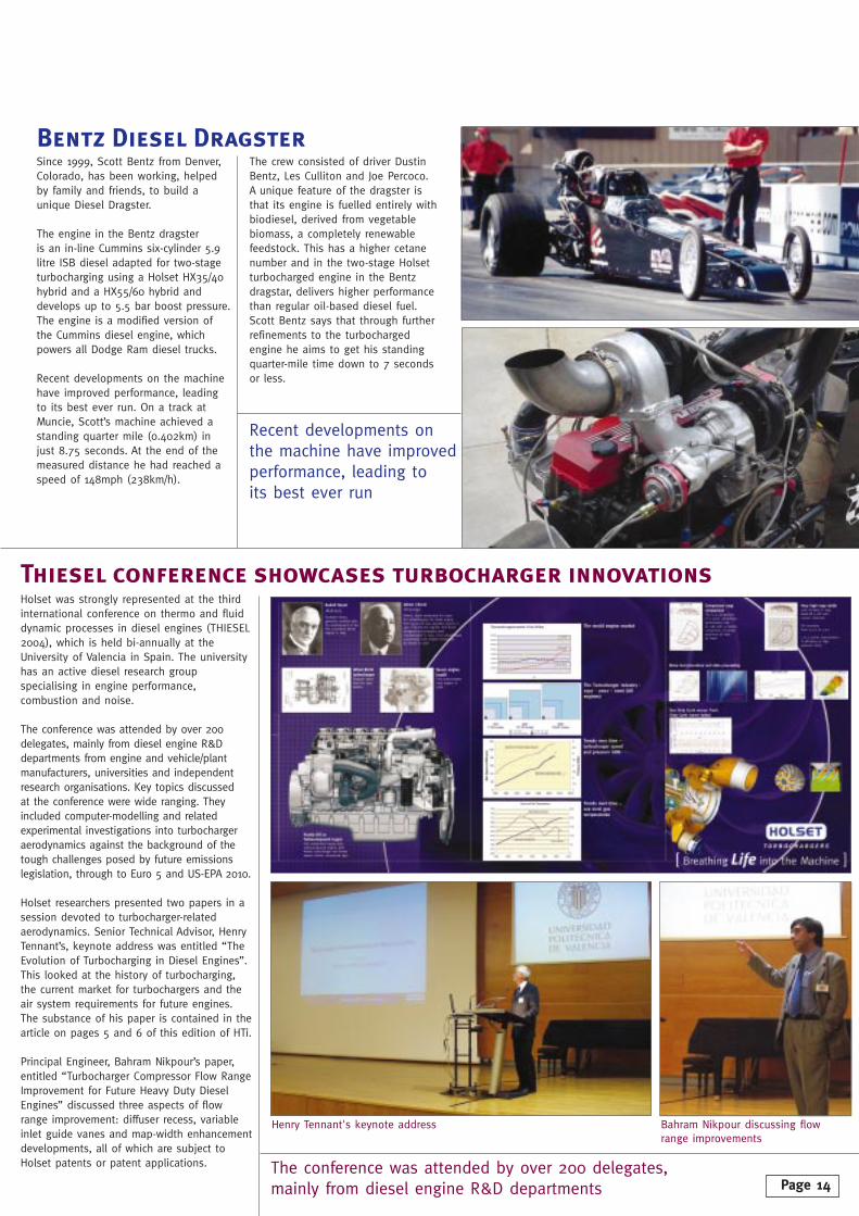
Since 1999, Scott Bentz from Denver,Colorado, has been working, helpedby family and friends, to build aunique Diesel Dragster.
The engine in the Bentz dragster is an in-line Cummins six-cylinder 5.9litre ISB diesel adapted for two-stageturbocharging using a Holset HX35/40hybrid and a HX55/60 hybrid anddevelops up to 5.5 bar boost pressure.The engine is a modified version ofthe Cummins diesel engine, whichpowers all Dodge Ram diesel trucks.
Recent developments on the machinehave improved performance, leadingto its best ever run. On a track atMuncie, Scott’s machine achieved astanding quarter mile (0.402km) injust 8.75 seconds. At the end of themeasured distance he had reached aspeed of 148mph (238km/h).
The crew consisted of driver DustinBentz, Les Culliton and Joe Percoco. A unique feature of the dragster isthat its engine is fuelled entirely withbiodiesel, derived from vegetablebiomass, a completely renewablefeedstock. This has a higher cetanenumber and in the two-stage Holsetturbocharged engine in the Bentzdragstar, delivers higher performancethan regular oil-based diesel fuel.Scott Bentz says that through furtherrefinements to the turbochargedengine he aims to get his standingquarter-mile time down to 7 secondsor less.
Bentz Diesel Dragster
Holset was strongly represented at the thirdinternational conference on thermo and fluiddynamic processes in diesel engines (THIESEL2004), which is held bi-annually at theUniversity of Valencia in Spain. The universityhas an active diesel research groupspecialising in engine performance,combustion and noise.
The conference was attended by over 200delegates, mainly from diesel engine R&Ddepartments from engine and vehicle/plantmanufacturers, universities and independentresearch organisations. Key topics discussed at the conference were wide ranging. Theyincluded computer-modelling and relatedexperimental investigations into turbochargeraerodynamics against the background of thetough challenges posed by future emissionslegislation, through to Euro 5 and US-EPA 2010.
Holset researchers presented two papers in asession devoted to turbocharger-relatedaerodynamics. Senior Technical Advisor, HenryTennant’s, keynote address was entitled “TheEvolution of Turbocharging in Diesel Engines”.This looked at the history of turbocharging,the current market for turbochargers and theair system requirements for future engines.The substance of his paper is contained in thearticle on pages 5 and 6 of this edition of HTi.
Principal Engineer, Bahram Nikpour’s paper,entitled “Turbocharger Compressor Flow RangeImprovement for Future Heavy Duty DieselEngines” discussed three aspects of flowrange improvement: diffuser recess, variableinlet guide vanes and map-width enhancementdevelopments, all of which are subject toHolset patents or patent applications.
Thiesel conference showcases turbocharger innovations
Recent developments onthe machine have improvedperformance, leading to its best ever run
The conference was attended by over 200 delegates, mainly from diesel engine R&D departments
Henry Tennant's keynote address Bahram Nikpour discussing flow range improvements
Page 14

Our GoalsHolset Turbochargers place the utmost importance on achieving high levels of product and service quality.
Our people are the single most valuable asset we have to ensure we meet your requirements. Through structuredtraining development programmes we encourage ouremployees to spend approximately 5% of their workingtime in training and personal development.
Our operations worldwide are certified to TS16949 qualitystandard and we welcome suggestions as to how we canfurther improve our performance to meet your needs.
We take our environmental obligations seriously and all our worldwide sites have achieved ISO14001. Our products have an important part to play in helping to improve engine emissions.
Our goal is to provide the lowest total cost solution for your turbocharging needs.
Part No. 3766118 Issue 3 Ref: AJS/OR