Comfort/nursing care bed...2 Dear valued customer, with your decision to purchase a comfort/nursing...
48
1 Assembly and operation manual Comfort/nursing care bed stellar
Transcript of Comfort/nursing care bed...2 Dear valued customer, with your decision to purchase a comfort/nursing...

1
Assembly and operation manual
Comfort/nursing care bed
stellar
2
Dear valued customer, with your decision to purchase a comfort/nursing care bed from Hermann Bock GmbH, you are receiving a long-lasting care product with superior functionality at the highest safety level. Our electrically operated com-fort/nursing care beds guarantee optimal lying comfort and allow profes-sional care at the same time. This product was designed with a focus on the elderly, whose confidence must be reinforced and whose life needs protec-tion. With this health care product, we meet these requirements. We urge you to prevent potential malfunctions and the risk of accidents by complying strictly with the safety and operating instructions and by carry-ing out the necessary maintenance.
Klaus Bock

3
Table of contents
1 Preface and general instructions ......................................................................... 4 1.1 Intended purpose .............................................................................................. 4 1.2 Definition of person groups .............................................................................. 5 1.3 Safety instructions ............................................................................................. 6 1.4 Service life / warranty ....................................................................................... 7 1.5 Requirements for the installation location ....................................................... 7 1.6 Type plate .......................................................................................................... 8
2 General description of the functions .................................................................. 10 3 Electric parts ..................................................................................................... 14
3.1 The drive unit .................................................................................................. 14 3.2 Caution: Electric drive ..................................................................................... 14 3.3 Drives ............................................................................................................... 15 3.4 The controller .................................................................................................. 15 3.5 The hand control ............................................................................................. 16 3.6 Cable hand switch - lock functions .................................................................. 17 3.7 Wireless hand switch for the domestic environment ..................................... 18
4 Assembly and operation .................................................................................... 21 4.1 Technical data ................................................................................................. 21 4.2 stellar ............................................................................................................... 23 4.3 Mounting the side rails.................................................................................... 32 4.4 Emergency lowering - back part (standard) .................................................... 35 4.5 Emergency lowering - back part (optional) ..................................................... 36 4.6 Change of location .......................................................................................... 37 4.7 Transport, storage and operating conditions .................................................. 37 4.8 Function notes ................................................................................................. 37 4.9 Disposal ........................................................................................................... 37 4.10 Troubleshooting .............................................................................................. 38
5 Accessories ........................................................................................................ 39 5.1 Special dimensions .......................................................................................... 39
6 Cleaning, maintenance and disinfection ............................................................ 40 6.1 Cleaning and care ............................................................................................ 40 6.2 Disinfection ..................................................................................................... 41 6.3 Avoidance of hazards ...................................................................................... 41
7 Guidance and manufacturer's declaration ......................................................... 43 8 Regular inspections with service ........................................................................ 45
4
1 Preface and general instructions
The various bed systems from Hermann Bock meet special requirements for the use in care and treatment facilities as well as for home care. Reliable functionality and a long product life make each bed particularly valuable. Our beds need little maintenance with proper operation and care. Each bed from Hermann Bock must pass quality testing in a final inspection before it is shipped anywhere. The beds are manufactured according to the current standards and compliant with the statutory requirements for medically used beds, and tested accordingly.
The nursing care beds comply with the EN 60601-2-52 standard. The electrical building components comply with safety standard EN 60601-1 for medical devices. Comfort beds that can be converted into full-fledged nursing care beds are medical devices, and are to be assigned to Class 1.
These standards divide the beds in five different areas of use:
1. Intensive care in a hospital; intensive care bed
2. Short-term care in a hospital or other medical facility; patient bed in the hospital
3. Long-term care in medical environment; stationary nursing care bed
4. Care at home, pure so-called “HomeCare bed”
5. Home-care nursing service
1.1 Intended purpose
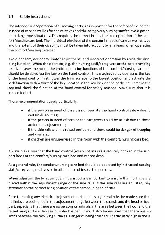
The comfort/nursing care bed is suitable for persons in the need of care (adults) who are at least 146 cm tall. The person's weight must not exceed 185 kg and must be over 40 kg. The body mass index (BMI = weight of the person (kg) / body height of the person (m)2) must be greater than or equal to 17.
The stellar may be used as a nursing care bed in homes for the elderly or nursing homes and rehabilitation facilities. It is used to alleviate a disability and/or to facilitate the lives of people who are in need of care or to make the work of their caregivers easier. Accord-ingly, the nursing care beds are designed to be used for the application environments 3 to 5. Furthermore, the stellar as a comfort bed was also designed as a convenient solution for the home care of frail and elderly people, as well as for the home care of people with disabilities. Accordingly, the comfort bed described below is intended for the application environment 4. Any other use is considered improper and is excluded from a possible liability claim.
The Trendelenburg function may not be used for this comfort / nursing care bed.

5
The comfort/nursing care bed is not suitable for the use in hospitals. It is also not designed to transport patients. The comfort/nursing care bed can only be moved within the pa-tient's room - even during a patient positioning - for example, for cleaning or to provide a better access to the patient.
The comfort/nursing care bed is suitable for the re-use. Please observe the instructions for cleaning, care and disinfection in these assembly and operation manual. Special atten-tion must also be paid to the information regarding the inspections.
Attention: The comfort/nursing care bed has no special connection options for an poten-tial equalisation. Electrical medical devices connected to the patient intravascular or in-tracardiac may not be used. The operator of the medical products has to ensure that the combination of the equipment meets the requirements of EN 60601-1.
This user manual contains safety instructions. All persons working with the com-fort/nursing care beds must be acquainted with the contents of these instructions. Im-proper operation can result in personal injuries.
1.2 Definition of person groups
Operator Operators (e.g. medical supply stores, specialist dealers, facilities and cost units) include all physical or juridical persons, who use the comfort/nursing care bed, or have the com-fort/nursing care bed used upon their order. The briefing on the use of the product shall generally be conducted by the operator.
User Users are persons whose training, experience or briefing on the product allows them to operate the comfort/nursing care bed or carry out works on it. The user is able to recog-nize possible hazards and/or to avoid them and to assess the health condition of the pa-tient.
Patient/resident Person with one or more disabilities, one or more activity restrictions, one or more par-ticipation restrictions or a combination thereof.
Qualified personnel Employees of the operator are referred to as qualified personnel. They are entitled to deliver the comfort/nursing care bed, assemble, dismantle and transport it, on the basis of their training or instructions. Besides knowing how to operate, mount and demount the comfort/nursing care bed, these persons must be instructed according to the guide-lines concerning the cleaning and disinfection of the comfort/nursing care bed.
6
1.3 Safety instructions
The intended use/operation of all moving parts is as important for the safety of the person in need of care as well as for the relatives and the caregivers/nursing staff to avoid poten-tially dangerous situations. This requires the correct installation and operation of the com-fort/nursing care bed. The individual physique of the person in need of care as well as type and the extent of their disability must be taken into account by all means when operating the comfort/nursing care bed.
Avoid dangers, accidental motor adjustments and incorrect operation by using the disa-bling function. When the operator, e.g. the nursing staff/caregivers or the care providing relative leaves the room, the entire operating functions of the comfort/nursing care bed should be disabled via the key on the hand control. This is achieved by operating the key of the hand control. First, lower the lying surface to the lowest position and activate the lock function with a twist of the key, located in the key lock on the backside. Remove the key and check the function of the hand control for safety reasons. Make sure that it is indeed locked.
These recommendations apply particularly:
– if the person in need of care cannot operate the hand control safely due to certain disabilities;
– if the person in need of care or the caregivers could be at risk due to those accidental adjustments;
– if the side rails are in a raised position and there could be danger of trapping and crushing,
– if children are unsupervised in the room with the comfort/nursing care bed.
Always make sure that the hand control (when not in use) is securely hooked in the sup-port hook at the comfort/nursing care bed and cannot drop.
As a general rule, the comfort/nursing care bed should be operated by instructed nursing staff/caregivers, relatives or in attendance of instructed persons.
When adjusting the lying surface, it is particularly important to ensure that no limbs are placed within the adjustment range of the side rails. If the side rails are adjusted, pay attention to the correct lying position of the person in need of care.
Prior to making any electrical adjustment, it should, as a general rule, be made sure that no limbs are positioned in the adjustment range between the chassis and the head or foot part, especially that there are no persons or animals in the area between the floor and the raised lying surface. In case of a double bed, it must also be ensured that there are no limbs between the two lying surfaces. Danger of being crushed is particularly high in these
7
areas. Always pay attention to objects that are near or even below the comfort/nursing care bed. This can lead to damages.
The permitted person’s weight depends on the total weight of the equipment that has been mounted to the bed (mattresses and other electronic medical devices). For safe working load, please refer to the type plate on the lying surface frame of the bed.
1.4 Service life / warranty
This comfort/nursing care bed was developed, designed and manufactured for a safe op-eration over a long period of time. With proper operation and maintenance, this com-fort/nursing care bed has an expected service life of 15 to 20 years. The service life de-pends on operating conditions and frequency.
Attention: Unauthorised technical changes to the product voids all warranty claims.
This product is not approved for the North American market, particularly not for the United States of America (USA). Distribution and use of the comfort/nursing care bed in these markets, including through third parties, is prohibited by the manufacturer.
1.5 Requirements for the installation location
The company Hermann Bock GmbH is not liable for damages which might arise from the daily usage on the floor.
To avoid floor indentations, floor should correspond to the recommendations of the FEB - Fachverband der Hersteller elastischer Bodenbeläge e. V. (Association of Elastic Floor Coverings Manufacturers). To do this, the technical information FEB No. 3 can be refer-enced.
Hazard note from BockSimultaneous use of electrical appliances particularly in the vicinity of the operational com-fort/nursing care bed may result in small electromagnetic interactions of these electric devices, e.g. static noise in the radio. In such rare events, increase the distance of the devices. Do not use the same socket or temporarily switch off the interference source and/or the disturbing or dis-turbed device. If the comfort / nursing care bed is operated with electrical or medical devices contrary to its
intended purpose, the functions of the comfort / nursing care bed must first be deactivated for
the duration of use via the integrated locking function in the hand control.
8
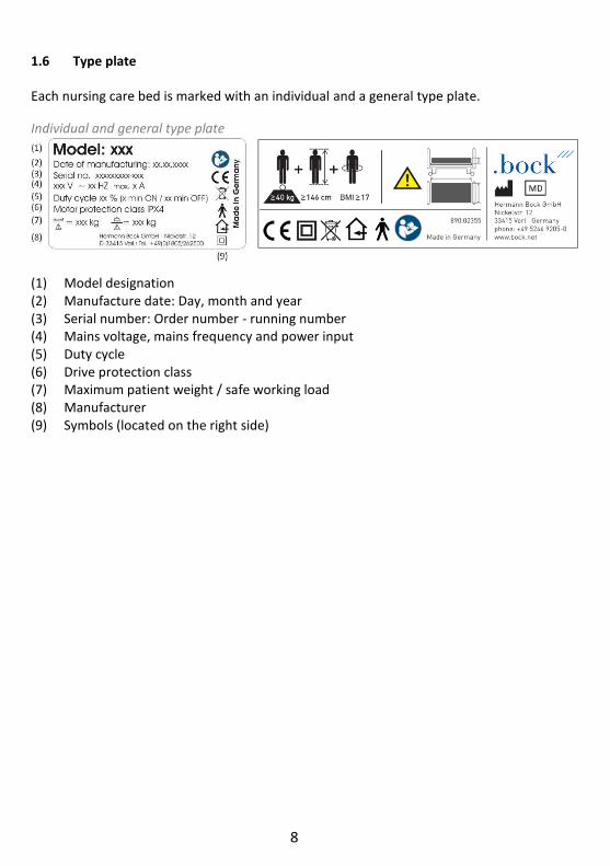
1.6 Type plate
Each nursing care bed is marked with an individual and a general type plate.
Individual and general type plate
(1) Model designation (2) Manufacture date: Day, month and year (3) Serial number: Order number - running number (4) Mains voltage, mains frequency and power input (5) Duty cycle (6) Drive protection class (7) Maximum patient weight / safe working load (8) Manufacturer (9) Symbols (located on the right side)

9
Explanation of the symbols:
Conformity mark according to the medical device regulation
Symbol for observance of the user manual
Within the European Union, this product must be disposed via the separated municipal waste. Product may not be dispo-sed of as household waste.
Medical application part type B
Use only in dry rooms
Protection class II (double insulation, insulated for protection)
IPX4 Protection of electrical equipment against splashing wa-ter
Symbol for maximum patient weight
Symbol for safe working load
Symbol for the identification of a medical device
Patient population
Follow the instructions appropriate for mattress size and thickness
Address of the manufacturer
MD

10
2 General description of the functions
Construction design and function
Corrosion protection The Hermann Bock GmbH comfort/nursing care beds are developed and constructed in such a way that they can function for a long time and safely. For this reason, all materials that may corrode are protected accordingly. All metal parts are equipped with a surface protection. The steel parts are either galvanised or stove-enamelled with a PES powder coating and the aluminium profiles are anodised.
The lying surface with 4 function areas The lying surface consists as standard of a slatted comfort frame (can alternatively be fit-ted with aluminium slats or special suspension systems) and is divided into four functional areas: Backrest, solid seat, upper and lower leg rest.
The comprehensive lying surface frame is welded from a steel/aluminium tube. The steel tubes are stove-enamelled with a PES-powder coating. The electric variable height adjust-ment of the lying surface is carried out with protective low-voltage DC motors (29 to 35V), and controlled with the smooth keys of the hand controller. The backrest can be adjusted electrically. The leg part consists of a foot support that is divided into two parts. With a touch of a button on the hand control, each individual position can be adjusted continu-ously. In case of a power failure the back part that can be lowered by loosening the tube clip.
The chassis The height adjustment of the comfort/nursing care bed is performed through a base frame with two individual drives. The surface of the tubular steel structure is stove-enam-elled with a PES-powder coating.
1 long back part
2 fixed seat part
3 upper leg rest
4 lower leg rest
11
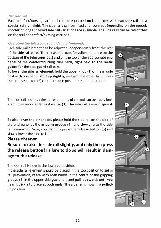
The side rail Each comfort/nursing care bed can be equipped on both sides with two side rails at a special safety height. The side rails can be lifted and lowered. Depending on the model, shorter or longer divided side rail variations are available. The side rails can be retrofitted on the stellar comfort/nursing care bed.
Operating the telescopic split side rails (optional) Each side rail element can be adjusted independently from the rest of the side rail parts. The release buttons for adjustment are on the bottom of the telescopic post and on the top of the appropriate end panel of the comfort/nursing care beds, right next to the metal guides for the side guard rail bars. To lower the side rail element, hold the upper knob (1) of the middle post with one hand, lift it up slightly, and with the other hand press the release button (2) on the middle post in the inner direction.
The side rail opens at the corresponding place and can be easily low-ered downwards as far as it will go (3). The side rail is now diagonal.
To also lower the other side, please hold the side rail on the side of the end panel at the gripping groove (4), and slowly raise the side rail somewhat. Now, you can fully press the release button (5) and slowly lower the side rail.
Please observe: Be sure to raise the side rail slightly, and only then press the release button! Failure to do so will result in dam-age to the release.
The side rail is now in the lowered position. If the side rail element should be placed in the top position to aid in fall prevention, reach with both hands in the centre of the gripping groove (6) in the upper side guard rail, and pull it upwards until you hear it click into place at both ends. The side rail is now in a pulled-up position.
12
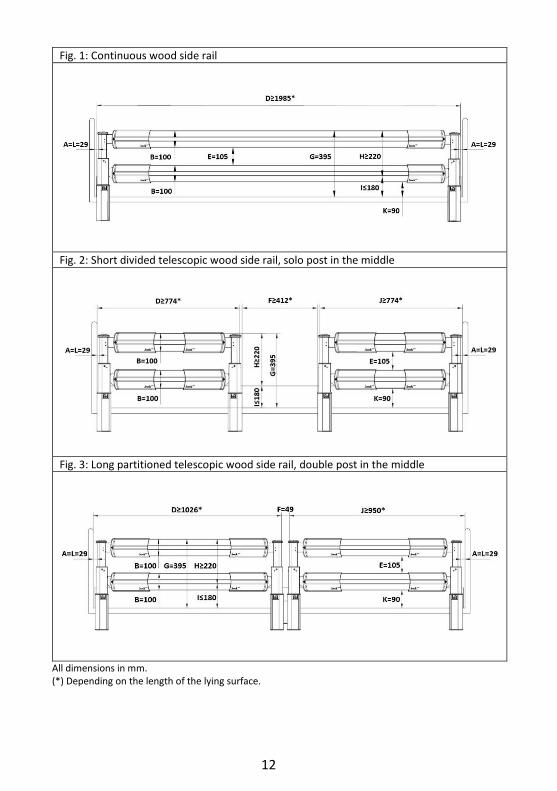
Fig. 1: Continuous wood side rail
Fig. 2: Short divided telescopic wood side rail, solo post in the middle
Fig. 3: Long partitioned telescopic wood side rail, double post in the middle
All dimensions in mm. (*) Depending on the length of the lying surface.
13
A: Distance between the head part and the side rail
B: Height 1 of side rail
C: Height 2 of side rail
D: Width 1 of the side rail
E: Distance between the elements within the side rail
F: Distance between the divided side rails
G: Distance between the lying surface and the upper edge of the side rail
H: Height of the top edge of the side rail above the mattress without compression
I: Thickness of the mattress for the intended use
J: Width 2 of the side rail
K: Smallest dimension between side rail and lying surface (or the panel, if any)
L: Distance between the foot part and the side rail
Designation item no.
Fig. 1: Continuous wood side rail
Wooden side rail (two bars) 91703
Fig. 2: Telescopic wooden side rail, solo post in the middle
Wooden side rail (two bars) 91868
Fig. 3: Telescopic wooden side rail, double post in the middle
Wooden side rail long head part (two bars) 91704
Wooden side rail short foot end (two bars) 91705
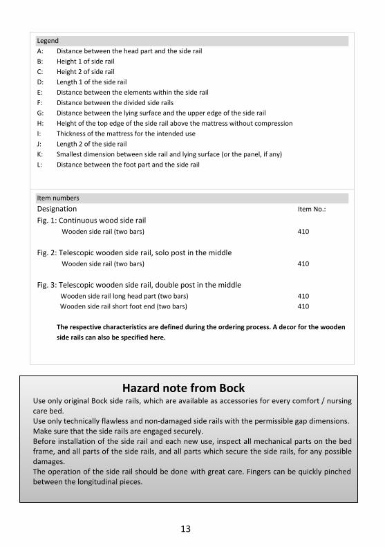
Legend
A: Distance between the head part and the side rail
B: Height 1 of side rail
C: Height 2 of side rail
D: Length 1 of the side rail
E: Distance between the elements within the side rail
F: Distance between the divided side rails
G: Distance between the lying surface and the upper edge of the side rail
H: Height of the top edge of the side rail above the mattress without compression
I: Thickness of the mattress for the intended use
J: Length 2 of the side rail
K: Smallest dimension between side rail and lying surface (or the panel, if any)
L: Distance between the foot part and the side rail
Item numbers
Designation Item No.:
Fig. 1: Continuous wood side rail
Wooden side rail (two bars) 410
Fig. 2: Telescopic wooden side rail, solo post in the middle
Wooden side rail (two bars) 410
Fig. 3: Telescopic wooden side rail, double post in the middle
Wooden side rail long head part (two bars) 410
Wooden side rail short foot end (two bars) 410
The respective characteristics are defined during the ordering process. A decor for the wooden
side rails can also be specified here.
Hazard note from Bock Use only original Bock side rails, which are available as accessories for every comfort / nursing care bed. Use only technically flawless and non-damaged side rails with the permissible gap dimensions. Make sure that the side rails are engaged securely. Before installation of the side rail and each new use, inspect all mechanical parts on the bed frame, and all parts of the side rails, and all parts which secure the side rails, for any possible damages. The operation of the side rail should be done with great care. Fingers can be quickly pinched between the longitudinal pieces.

14
3 Electric parts
3.1 The drive unit
The drive unit consists of individual drives for the electrical adjustment of the back and leg rest part. The level adjustment is performed with two individual drives that are at-tached to the chassis. The adjustment range of these individual drives is determined via Hall sensors. The motors and the hand control are connected to the inner control box. The internal control box includes a switch box with a rectifier in which the input voltage is converted into a protective low voltage of max. 29 VDC direct current. The motors, con-troller and the hand control function with this non-hazardous low protective voltage. The cables are double-insulated and the mains plug has a primary fuse.
A power adjustment provides constant function speed. Therefore, the safety functions comply with protection class II and the moisture barrier protection type IPX4.
The maximum duty cycle is specified on the (type plate) of the comfort/nursing care bed. For example, 10% duty cycle (2 min. ON / 18 min. OFF) means that any electronic adjust-ment can be performed for a max. of 2 minutes within a timeframe of 20 minutes (pro-tection against overheating).
If the maximum setting time of two minutes is exceeded by two minutes (e.g. someone plays continuously with the hand control), which could lead to overheating of the control-ler or drives, the thermal fuse immediately shuts off the power supply to the com-fort/nursing care bed. After a cooling time of approx. one hour, the power supply in the controller is automatically restored.
3.2 Caution: Electric drive
The electrically operated comfort/nursing care bed enables the persons in the need of care to support the recovery process psychologically and physically and at the same time relieve pain through its various functions. As medical products, electrically operated com-fort/nursing care beds require special care with regard to constant safety checks. This in-cludes a safety-conscious handling of the comfort/nursing care bed, daily inspection of electrical equipment and a proper maintenance and cleaning.
To prevent damages to the cables, wiring should be conducted outside of the area in which damages could be caused. Furthermore, avoid touching the sharp parts. To prevent injury through an electric shock, avoid the possibilities of too high contact voltages. These circumstances may especially be the case if the power cable is damaged, if inadmissible and excessive leakage currents exist, or if liquid was spilled into the motor housing, e.g. during improper cleaning. This damage can cause malfunction of the controller, which could result in unwanted movements of single bed elements, posing a risk of injury for the operator and the person in need of care.

15
3.3 Drives
Hermann Bock GmbH equips comfort/nursing care beds with drive systems from the com-pany DewertOkin GmbH.
Each drive consists always of four main components. – Housing
– Motor
– Gear
- Spindle with nut
The housing principle of the individual drive guarantees the permanent function of all drive components. Through a detailed interior structure, the construction of the housing interior creates an essential prerequisite for the precise integration of the drive technol-ogy, as well as a trouble-free assembly/disassembly.
3.4 The controller
Controller comfort/nursing care bed stellar - front side
The stellar comfort/nursing care bed is equipped with a controller system from Dew-ertOkin GmbH. Four drives can be connected to the controller (sockets 4, 5, 6 and 7). The colour coding can be found in chapter 4 "Assembly and operation". Y-cabling is connected to the connection socket for the hand control (socket 2). Make sure that a dummy plug is fitted to the connection for the fifth motor (socket 3) and that a red jumper plug is plugged into the connection for a second controller (socket 1).
16
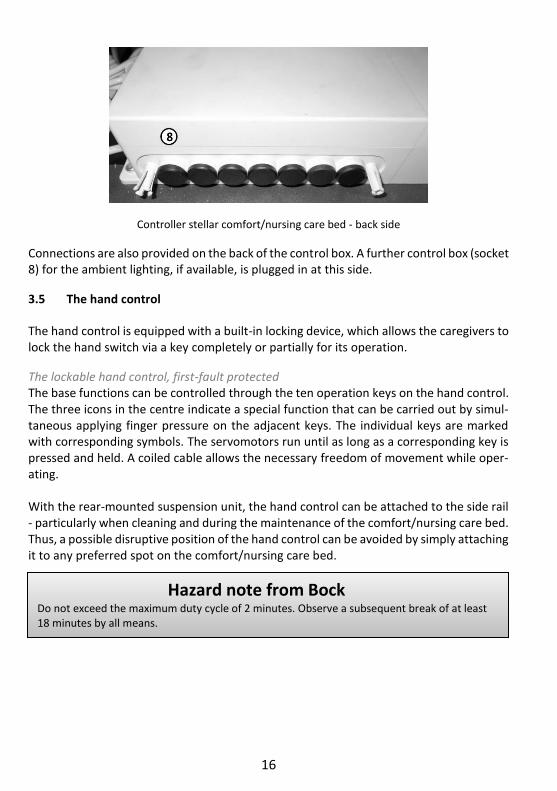
Controller stellar comfort/nursing care bed - back side
Connections are also provided on the back of the control box. A further control box (socket 8) for the ambient lighting, if available, is plugged in at this side.
3.5 The hand control
The hand control is equipped with a built-in locking device, which allows the caregivers to lock the hand switch via a key completely or partially for its operation.
The lockable hand control, first-fault protected The base functions can be controlled through the ten operation keys on the hand control. The three icons in the centre indicate a special function that can be carried out by simul-taneous applying finger pressure on the adjacent keys. The individual keys are marked with corresponding symbols. The servomotors run until as long as a corresponding key is pressed and held. A coiled cable allows the necessary freedom of movement while oper-ating. With the rear-mounted suspension unit, the hand control can be attached to the side rail - particularly when cleaning and during the maintenance of the comfort/nursing care bed. Thus, a possible disruptive position of the hand control can be avoided by simply attaching it to any preferred spot on the comfort/nursing care bed.
Hazard note from Bock Do not exceed the maximum duty cycle of 2 minutes. Observe a subsequent break of at least 18 minutes by all means.
17
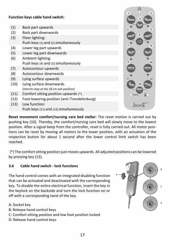
Function keys cable hand switch:
Reset movement comfort/nursing care bed stellar: The reset motion is carried out by pushing key (10). Thereby, the comfort/nursing care bed will slowly move to the lowest position. After a signal beep from the controller, reset is fully carried out. All motor posi-tions can be reset by moving all motors to the lower position, with an actuation of the respective button for about 1 second after the lower control limit switch has been reached. (*) The comfort sitting position just moves upwards. All adjusted positions can be lowered by pressing key (13).
3.6 Cable hand switch - lock functions
The hand control comes with an integrated disabling function that can be activated and deactivated with the corresponding key. To disable the entire electrical function, insert the key in the keylock on the backside and turn the lock function on or off with a corresponding twist of the key.
A: Socket key B: Release hand control keys C: Comfort sitting position and low foot position locked D: Release hand control keys
(1) Back part upwards
(2) Back part downwards
(3) Floor lighting: Push keys (1) and (2) simultaneously
(4) Lower leg part upwards
(5) Lower leg part downwards
(6) Ambient lighting: Push keys (4) and (5) simultaneously
(7) Autocontour upwards
(8) Autocontour downwards
(9) Lying surface upwards
(10) Lying surface downwards
(Interim stop at the 58 cm exit position) (11) Comfort sitting position upwards (*)
(12) Foot-lowering position (anti-Trendelenburg)
(13) Low function: Push keys (11) and (12) simultaneously
18
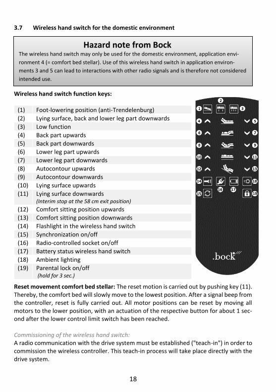
3.7 Wireless hand switch for the domestic environment
Wireless hand switch function keys:
Reset movement comfort bed stellar: The reset motion is carried out by pushing key (11). Thereby, the comfort bed will slowly move to the lowest position. After a signal beep from the controller, reset is fully carried out. All motor positions can be reset by moving all motors to the lower position, with an actuation of the respective button for about 1 sec-ond after the lower control limit switch has been reached. Commissioning of the wireless hand switch: A radio communication with the drive system must be established ("teach-in") in order to commission the wireless controller. This teach-in process will take place directly with the drive system.
(1) Foot-lowering position (anti-Trendelenburg)
(2) Lying surface, back and lower leg part downwards
(3) Low function
(4) Back part upwards
(5) Back part downwards
(6) Lower leg part upwards
(7) Lower leg part downwards
(8) Autocontour upwards
(9) Autocontour downwards
(10) Lying surface upwards
(11) Lying surface downwards
(Interim stop at the 58 cm exit position)
(12) Comfort sitting position upwards
(13) Comfort sitting position downwards
(14) Flashlight in the wireless hand switch
(15) Synchronization on/off
(16) Radio-controlled socket on/off
(17) Battery status wireless hand switch
(18) Ambient lighting
(19) Parental lock on/off (hold for 3 sec.)
Hazard note from Bock The wireless hand switch may only be used for the domestic environment, application envi-
ronment 4 (= comfort bed stellar). Use of this wireless hand switch in application environ-
ments 3 and 5 can lead to interactions with other radio signals and is therefore not considered
intended use.
19
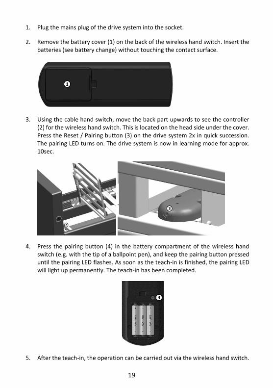
1. Plug the mains plug of the drive system into the socket.
2. Remove the battery cover (1) on the back of the wireless hand switch. Insert the batteries (see battery change) without touching the contact surface.
3. Using the cable hand switch, move the back part upwards to see the controller (2) for the wireless hand switch. This is located on the head side under the cover. Press the Reset / Pairing button (3) on the drive system 2x in quick succession. The pairing LED turns on. The drive system is now in learning mode for approx. 10sec.
4. Press the pairing button (4) in the battery compartment of the wireless hand switch (e.g. with the tip of a ballpoint pen), and keep the pairing button pressed until the pairing LED flashes. As soon as the teach-in is finished, the pairing LED will light up permanently. The teach-in has been completed.
5. After the teach-in, the operation can be carried out via the wireless hand switch.

20
6. Close the battery compartment with the battery cover on the back of the wireless hand switch.
If the drive does not start when the button is pressed, release the button briefly and press it again. If necessary, repeat the teach-in procedure.
Battery change: 1. Remove the battery cover on the back of the wireless hand switch.
2. Insert the three batteries (AAA) into the battery compartment.
3. Close the battery compartment with the battery cover on the back of the wireless hand switch.
Hazard note from Bock All drive components must not be opened! Troubleshooting or exchanging single electrical components may only be performed only by special qualified personnel.
Hazard note from Bock The motors meet the water protection standard IPX4. Do not squeeze/crush the cables. Adjust-ment of moving parts may only be used for the intended use. Hermann Bock GmbH assumes no liability for unauthorized technical changes. .
Hazard note from Bock
Do not try to fix failures on the electrical equipment itself. It could be fatal! Either call the cus-tomer service of Hermann Bock GmbH or an authorised/licensed electrician who conducts the troubleshooting in compliance with all relevant VDE regulations and safety regulations.
21
4 Assembly and operation
4.1 Technical data
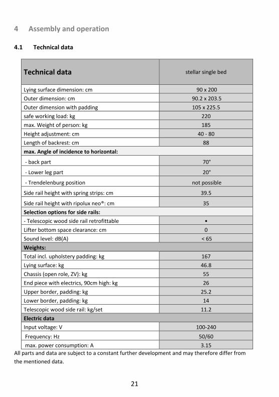
Technical data stellar single bed
Lying surface dimension: cm 90 x 200
Outer dimension: cm 90.2 x 203.5
Outer dimension with padding 105 x 225.5
safe working load: kg 220
max. Weight of person: kg 185
Height adjustment: cm 40 - 80
Length of backrest: cm 88
max. Angle of incidence to horizontal:
- back part 70°
- Lower leg part 20°
- Trendelenburg position not possible
Side rail height with spring strips: cm 39.5
Side rail height with ripolux neo®: cm 35
Selection options for side rails:
- Telescopic wood side rail retrofittable •
Lifter bottom space clearance: cm 0
Sound level: dB(A) < 65
Weights:
Total incl. upholstery padding: kg 167
Lying surface: kg 46.8
Chassis (open role, ZV): kg 55
End piece with electrics, 90cm high: kg 26
Upper border, padding: kg 25.2
Lower border, padding: kg 14
Telescopic wood side rail: kg/set 11.2
Electric data
Input voltage: V 100-240
Frequency: Hz 50/60
max. power consumption: A 3.15
All parts and data are subject to a constant further development and may therefore differ from
the mentioned data.

22
Technical data stellar double bed
Lying surface dimension: cm 180 x 200
Outer dimension: cm 181 x 203.5
Outer dimension with padding 195 x 225.5
safe working load per bed: kg 220
max. Weight of person per bed: kg 185
Height adjustment: cm 40 - 80
Length of backrest: cm 88
max. Angle of incidence to horizontal:
- back part 70°
- Lower leg part 20°
- Trendelenburg position not possible
Side rail height with spring strips: cm 39.5
Side rail height with ripolux neo®: cm 35
Selection options for side rails:
- Telescopic wood side rail retrofittable •
Lifter bottom space clearance: cm 0
Sound level: dB(A) < 65
Weights:
Total incl. upholstery padding: kg 303.8
Per lying surface: kg 46.8
Per chassis (open roll, ZV): kg 55
End piece with electrics, 90cm high: kg 52
Upper border, padding: kg 31.4
Lower border, padding: kg 16.8
Telescopic wood side rail: kg/set 11.2
Electric data
Input voltage: V 100-240
Frequency: Hz 50/60
max. power consumption: A 3.15
All parts and data are subject to a constant further development and may therefore differ from the mentioned data.

23
4.2 stellar
A comfort/nursing care bed for all circumstances that unifies technology and comfort. Technically perfected down to the last detail: The stellar can be equipped with various lighting systems. In addition, USB connections and 230V sockets can be installed in the comfort bed. The side rails can be retrofitted. This comfort/nursing care bed provides a high degree of comfort to frail people, persons in the need of care and people with disa-bilities, thus facilitating an optimal care through a high lying comfort and an easy opera-tion.
- The stellar is not suitable for hospital use. - The comfort/nursing care bed stellar is not suitable for the transport of the pa-
tient. The comfort/nursing care beds may only be moved for cleaning purposes inside the patient’s room or to allow access to the patient.
- The comfort/nursing care bed is suitable for persons in the need of care (adults) who are at least 146 cm tall. The person's weight must not exceed 185 kg and must be over 40 kg. The body mass index (BMI) must be greater than or equal to 17.
- Under certain circumstances the stellar can be used (if necessary) for medical purposes with other electric medical equipment (e.g. suction devices, ultrasonic humidifier, food systems, anti-bedsore systems, oxygen concentrators and simi-lar devices). In this event, disable all bed functions for the duration of the appli-cation via the integrated disabling function.
Attention: The comfort/nursing care bed has no special connection options for a potential equalisation. Electrical medical devices connected to the patient intravascular or intracar-diac may not be used. The operator of the medical products has to ensure that the com-bination of the equipment meets the requirements of EN 60601-1.

24
stellar becomes operational
Remove all packaging from the com-fort/nursing care bed and place the chassis on a free level surface.
.
Place the cross beam (1) including the con-troller on the chassis (2).
Pay attention to the head and leg end.
On the left side of the Fig. you can see the mountings for an end piece, and these are to be placed in the head area. On one side of the cross beam, a receiver is visible un-der the sheet metal cladding. This must also be aligned on the head side.
Place the cross beam on the chassis so that the holes are on top of each other. Fasten the lying surface with the 4 screws (3) sup-plied (cylinder head screws M8x55) and the 4 nuts.
Place the lying surface on the cross beam.
Pay attention to the head and leg end.
On the left side of the Fig. you can see the mountings for an end piece, and these must be placed in the head area of the lying surface.
The strips of the lying surface can be re-moved for the assembly.
Slide the lying surface on the chassis so that the holes are aligned on top of each
25
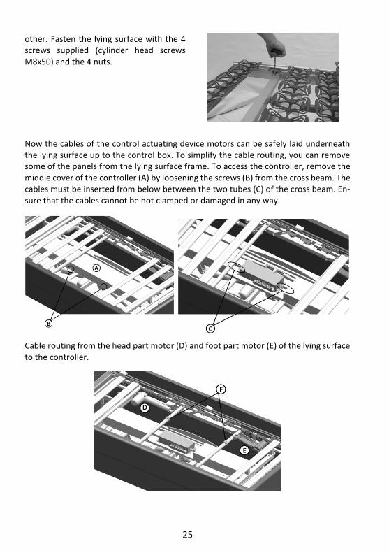
other. Fasten the lying surface with the 4 screws supplied (cylinder head screws M8x50) and the 4 nuts.
Now the cables of the control actuating device motors can be safely laid underneath the lying surface up to the control box. To simplify the cable routing, you can remove some of the panels from the lying surface frame. To access the controller, remove the middle cover of the controller (A) by loosening the screws (B) from the cross beam. The cables must be inserted from below between the two tubes (C) of the cross beam. En-sure that the cables cannot be not clamped or damaged in any way.
Cable routing from the head part motor (D) and foot part motor (E) of the lying surface to the controller.
26
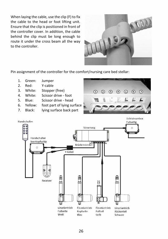
When laying the cable, use the clip (F) to fix the cable to the head or foot lifting unit. Ensure that the clip is positioned in front of the controller cover. In addition, the cable behind the clip must be long enough to route it under the cross beam all the way to the controller.
Pin assignment of the controller for the comfort/nursing care bed stellar:
1. Green: Jumper 2. Red: Y-cable 3. White: Stopper (free) 4. White: Scissor drive - foot 5. Blue: Scissor drive - head 6. Yellow: foot part of lying surface 7. Black: lying surface back part

27
Please also refer to the description of the controller in chapter 3.
After all plugs have been connected to the controller, you may connect the supplied cover cap to the controller so that the connectors are securely fastened.
The hand control is connected to a sep-arate control box (G) located in the head area. To do this, a further part of the cover must be removed (as de-scribed above for points A and B). The hand control is then plugged into the hand control box. Use the plug socket which points in the direction of the (head) end piece.
After all plugs have been connected to the hand control box, you may connect the supplied cover cap to the controller so that the connectors are securely fas-tened.
Attention: If your comfort bed is factory-equipped with a floor lighting, you must insert the hand control into the free socket of one of the two floor lighting units. The floor lighting is already mounted on the lying surface frame. In this case, the plug of the floor lighting must be inserted into the socket for the hand control (red mark) on the controller. Ensure that all sockets are subsequently covered with the locking caps, in order to guarantee the protection class requirements.
Route the power cable in the middle across the frame of the chassis, all the way to the head end piece. There, please screw on the cable with the help of the strain relief.
28
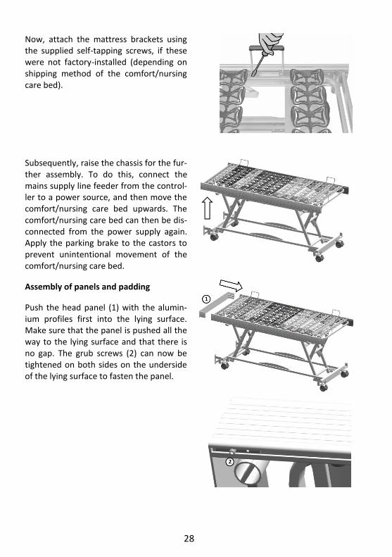
Now, attach the mattress brackets using the supplied self-tapping screws, if these were not factory-installed (depending on shipping method of the comfort/nursing care bed).
Subsequently, raise the chassis for the fur-ther assembly. To do this, connect the mains supply line feeder from the control-ler to a power source, and then move the comfort/nursing care bed upwards. The comfort/nursing care bed can then be dis-connected from the power supply again. Apply the parking brake to the castors to prevent unintentional movement of the comfort/nursing care bed.
Assembly of panels and padding
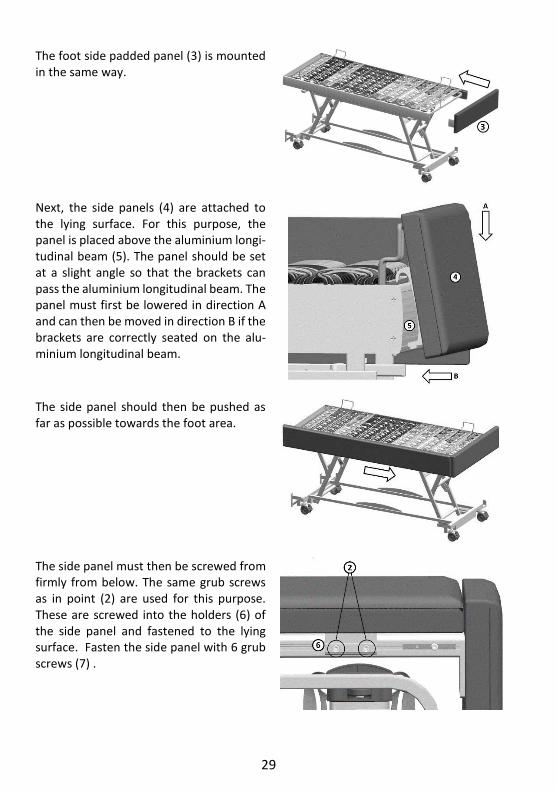
Push the head panel (1) with the alumin-ium profiles first into the lying surface. Make sure that the panel is pushed all the way to the lying surface and that there is no gap. The grub screws (2) can now be tightened on both sides on the underside of the lying surface to fasten the panel.
29
The foot side padded panel (3) is mounted in the same way.
Next, the side panels (4) are attached to the lying surface. For this purpose, the panel is placed above the aluminium longi-tudinal beam (5). The panel should be set at a slight angle so that the brackets can pass the aluminium longitudinal beam. The panel must first be lowered in direction A and can then be moved in direction B if the brackets are correctly seated on the alu-minium longitudinal beam.
The side panel should then be pushed as far as possible towards the foot area.
The side panel must then be screwed from firmly from below. The same grub screws as in point (2) are used for this purpose. These are screwed into the holders (6) of the side panel and fastened to the lying surface. Fasten the side panel with 6 grub screws (7) .

30
The same procedure is then repeated for the other side so that the panels are com-pletely mounted on the lying surface.
The chassis of the stellar comfort/nursing care bed is also fitted with a panel cover-ing. The first step here is to mount the side panels. These side panels are equipped with two different mountings. The U brack-ets (8) can be attached to the mountings (9) on the chassis provided for this pur-pose. The panel must thereby be pushed down as far as possible.
Attention: The unneeded long mounting, shown here in the right Fig. is pointing to the foot end!
The second panel can then be mounted on the chassis.
The last panel (10) for the chassis is in-serted on the foot side. There are two black wedges (11) located on this panel, which are used for fixing and connecting the side panels. Slide the wedges evenly over the holders (12) provided for this purpose, and push the panel downwards in the direction of the arrow.
Ensure that all panel are positioned at the same height. If this is not the case, the screws on the brackets can be loosened slightly, and the panels can be brought into the appropriate positions. Afterwards, tighten the screws of the brackets again.
31
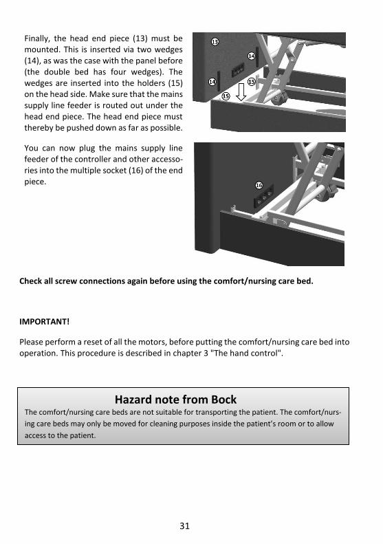
Finally, the head end piece (13) must be mounted. This is inserted via two wedges (14), as was the case with the panel before (the double bed has four wedges). The wedges are inserted into the holders (15) on the head side. Make sure that the mains supply line feeder is routed out under the head end piece. The head end piece must thereby be pushed down as far as possible.
You can now plug the mains supply line feeder of the controller and other accesso-ries into the multiple socket (16) of the end piece.
Check all screw connections again before using the comfort/nursing care bed.
IMPORTANT!
Please perform a reset of all the motors, before putting the comfort/nursing care bed into operation. This procedure is described in chapter 3 "The hand control".
Hazard note from Bock The comfort/nursing care beds are not suitable for transporting the patient. The comfort/nurs-
ing care beds may only be moved for cleaning purposes inside the patient’s room or to allow
access to the patient.

32
4.3 Mounting the side rails
The comfort/nursing care bed stellar can be equipped with side rails. The comfort/nursing care bed should be moved to its uppermost position (1) to enable the instal-lation of the side rails. This considerably simplifies the as-sembly.
In order to install the side rails, the side padding must be removed. This is attached to the lying surface at three points (2).
Remove the six grub screws (3) that secure the side panel to the lying surface. This requires a size 4 Allen key. The screws are located underneath the lying surface.
When all screws have been removed, the side panels (4) can be removed from the lying surface. To do this, grip the lower edge of the panel and pull it away from the comfort/nursing care bed. The panel can then be lifted upwards from the aluminium longitudinal beam.
Now the telescopic posts can be mounted on the lying surface. To do this, hang the telescopic post with the bracket into the aluminium longitudinal beam. This tele-scopic post must then be pushed towards the end of the lying surface (5). Make sure that this is not pushed be-yond the length of the lying surface. The lying surface must still be visible when viewed from the front.

33
The telescopic post must now be fastened. For this, the supplied M8 grub screws must be screwed into the two threaded holes (6). Tighten the grub screws evenly so that the telescopic post has a firm hold. Make sure that the distance between the telescopic post and end piece is smaller than 60mm.
The side rail can now be attached onto the telescopic post. To do this, slide the opening of the plastic cap over the bracket of the telescopic post. Make sure that the side rails are correctly aligned with the brackets (see illus-tration)! The opening in the plastic parts points down-wards. The lettering ". bock ´´´" should be legible on the plastic parts.
Proper view from below
The hole in the plastic parts of the side rails must now be above the hole in the telescopic posts. If this is the case, the sleeve nut (9) can be inserted through the side rail. The flat screw (8) can then be inserted and tightened from the other side.
Ensure that all screws (10) are present and fastened hand-tight. If this is not the case, there is a risk that the side rails will fall out during the first adjustment.

34
The second telescopic post must then be mounted. In this case another single telescopic post (11) was selected. Al-ternatively, this can also be a double telescopic post. Push the side rails with their plastic parts together as far as possible. Now the telescopic post can be placed on the al-uminium longitudinal beam. Push the telescopic post into the openings of the plastic caps as before. Afterwards, fasten the side rails with the screws. In the case of contin-uous side rails, the plastic caps may have to be pulled out slightly so that they can be mounted.
Inserting the decorative foil into the telescopic posts Take the decorative foil (1) and push it from below through the slot in the plug (2) into the aluminium profile of the side rail post (3). Please make sure that the correct side of the decorative film is facing outwards. This will be difficult to remove later. Push the decorative foil in until it is flush with the button (4). On the lower plug (2) there is a snap-in lug which prevents the decorative foil from falling out.

35
4.4 Emergency lowering - back part (standard)
In case of power or drive system failure, you can lower the elevated back part manually.
Must be carried out always by two people!
One person lifts the back part slightly (to take pressure off) and holds it in this posi-tion. As next step, the second person re-moves the locking pin from the motor.
The motor is now separated from the back part and can be swivelled downwards.
Once the second person has left the danger zone, the first person can lower gently the back part.
Hold the back part by all means until it is fully lowered.
Hazard note from Bock Emergency lowering may be only carried out in an emergency by people who safely master this operation. Always disconnect the comfort / nursing care beds from the power supply as long as the motor has not been remounted.
36
4.5 Emergency lowering - back part (optional)
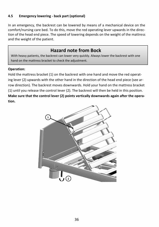
In an emergency, the backrest can be lowered by means of a mechanical device on the comfort/nursing care bed. To do this, move the red operating lever upwards in the direc-tion of the head end piece. The speed of lowering depends on the weight of the mattress and the weight of the patient.
Operation:
Hold the mattress bracket (1) on the backrest with one hand and move the red operat-
ing lever (2) upwards with the other hand in the direction of the head end piece (see ar-
row direction). The backrest moves downwards. Hold your hand on the mattress bracket
(1) until you release the control lever (2). The backrest will then be held in this position.
Make sure that the control lever (2) points vertically downwards again after the opera-
tion.
Hazard note from Bock With heavy patients, the backrest can lower very quickly. Always lower the backrest with one
hand on the mattress bracket to check the adjustment.

37
4.6 Change of location
If the comfort/nursing care bed must be moved to another location, please follow these safety instructions:
– Move the lying surface into the lowest position using the button (10) of the hand control.
– Before conducting a movement, pull the mains plug and fasten it to the top of the lying surface, in order to secure the power cable against falling down and getting run over. Make sure that the cable is not dragged over the floor.
– Before inserted the mains plug again, inspect the power cable visually for me-chanical damage (dents and kinks, abrasions and bare wires).
– Place the power cable in a way that it will not be rolled over by the comfort/nurs-ing care bed, or strained during the operation of the comfort/nursing care bed, or could become damaged when inserting the mains plug again.
– Carry out a reset run as described in chapter 3 "The hand control"
4.7 Transport, storage and operating conditions
Transport and storage Operation
Temperature 0°C to +40°C 10°C to +40°C
Relative humidity 20% to 80% 20% to 70%
Air pressure 800hPa to 1060hPA
4.8 Function notes
Lock the brakes on the castors to keep the comfort/nursing care bed in one location. To accomplish this, use your foot to move the locking lever on each castor downwards.
If necessary, pull the side rails up until they lock into place. When using mattresses of different thickness, the minimum height of 22 cm, measured from the top edge of the side rail above the mattress without compression, may not be underrun (additionally, a third attachment guard must be used, which is available as an accessory).
4.9 Disposal
Each of the components made of plastic, metal, padding and wood are recyclable and can be disposed/recycled in compliance with the relevant legal provisions. Please note that electrically adjustable comfort/nursing care bed are considered commercially used elec-tronic scrap (b2b) according to the WEEE-EC directive 2012/19/EC. All replaced electrical and electronic components of the electrical adjustment system must be handled in ac-cordance with the requirements of the Electrical and Electronic Equipment Act (ElektroG) and disposed of properly.

38
4.10 Troubleshooting
This overview helps you to detect and correct malfunctions on your own and explains, what kind of malfunctions require the consultation of suitably qualified service personnel.
Malfunction Potential causes Remedy The drive units cannot be con-trolled via the hand control
Power cable is not connected Insert power cable
Signals of the drives for the height adjust-ment are incorrectly processed within the controller
Carry out the reset run as de-scribed in Chapter 3 "The hand control".
No voltage in the socket Check the socket or the fuse box
Plug connector of the hand control not fixed firmly
Check the plug-in connection on the motor
Hand control or drive unit defective Notify the operator or Bock customer service
Disabling function or control box in the hand control activated
Disabling function or control box in the hand control deac-tivated
When buttons are pressed, the drive units stop after a short time
There is an obstruction in the adjustment range
Remove obstruction
The safe working load has been exceeded Reduce the load
The drives stop after a longer adjustment time
The adjustment time or safe working load has been exceeded and the polyswitch in the transformer of the controller has re-sponded to increased heat
Allow the drive system to cool down sufficiently for at least one minute
Opposite functions when oper-ating the hand control
Check the pin assignments on the control-ler, see Chapter 4.2
Notify the operator or Bock customer service
Individual drive units run in one direction only
Hand control, drive unit or controller de-fective
Notify the operator or Bock customer service
Drive units stop and bed re-mains in a tilted position
Constant operation of adjustment func-tions
Move lying surface in bottom or top position as this will straighten it again horizontally. Activate disabling function in hand control

39
5 Accessories
Hermann Bock GmbH offers practical and mobility-promoting accessories to ensure that each comfort/nursing care bed is tailored even more precisely to the individual needs of the persons in the need of care. The installation is carried out in a quick and easy manner using the fixing points on the comfort/nursing care bed that have already been prepared for this purpose. It goes without saying that every element of our additional equipment offer meets the special quality and safety standards of Bock. In addition to the standard accessories included in basic equipment, the customer can also choose from our variety of accessories, which is available for each comfort/nursing care bed model. These optional accessories vary depending on the bed model and are fitted to its special functions and location of use. The range stretches from technical elements over mattresses up to the occasional extra bed. A wide range of wooden finishes and a variety of colours allow for the harmonious integration of each comfort/nursing care bed into any kind of furniture environment.
5.1 Special dimensions
Special dimensions are an essential part of the production Hermann Bock GmbH. Optimal lying comfort for persons in need of care who have a particular physique can only be achieved by means of custom-built models. With its customized models, Hermann Bock GmbH enables customers to have their comfort/nursing care bed tailored to fit the indi-vidually physical requirements of the person in need of care. From a height of 180 cm, Hermann Bock GmbH recommends the use of a comfort/nursing care bed with a lying surface length of 220 cm. This enables even tall people to lie comfortably while maintain-ing the same level of functionality.
Hazard note from Bock When using accessories on the comfort/nursing care bed or medically necessary devices such as infusion stands in close proximity to the bed, ensure particularly that there are no risks of crushing or shearing for the person in need of care when adjusting the back and leg rests. The representative of the service hotline of Hermann Bock are looking forward to informing you about the best retrofitting solution for your bed. Hotline no. 0180 5262500 (14 cents/min. for calls from landline phones, 42 cents/min. for calls from mobile phones). A wide product range of auxiliary furniture complements the various bed models up to the com-plete interior design of your home. This combination creates a care and living comfort resulting in perfect harmony.
40
6 Cleaning, maintenance and disinfection
The individual bed elements consist of high quality materials. The surfaces of the steel tubes is covered with a durable polyester-powder coating. All surfaces of the wooden parts are surface-sealed with an ecologically coating that is low on harmful substances. All bed elements are easy to clean and cared for using wipe and spray disinfection means according to the applicable cleaning requirements with respect to the various areas of application. Observing the following care instructions will retain the usability and visual appearance of your comfort/nursing care bed for a long time to come.
6.1 Cleaning and care
Steel tubes and vanished metal parts: Please use a wet wipe and a regular mild household detergent for the cleaning and care of these surfaces.
Wooden-, decorative-, and plastic elements: All standard furniture cleaners and cleaning detergents can be used. Using a wet wipe without detergent additives for the cleaning of the plastic elements should generally be sufficient. For care of the plastic surfaces use a product that is specifically suitable for plastics.
Drive: To prevent the intrusion of moisture into the motor housing, we recommended using only a damp rag to clean outside housing.
Spring systems ripolux neo: Use a damp rag without adding any detergents, or, if deemed necessary, a detergent that is exclusively suitable for plastics and clean the spring elements made of plastics. In case of heavy contamination, remove the spring elements from the supporting elements and the supporting elements from the frame of the lying surface. The dismounted plastics el-ements can be rinsed or spray-washed with hot water to get them clean. For the disinfec-tion, the components should be sprayed with a detergent suitable for plastics. Most of the moisture drips off the plastic surface by slightly shaking it, while the rest will dry on its own within a very short time. Remount the elements after they have completely dried. If required, you can also remove each of the individual lying surface elements completely from the frame to clean them.
41
Cover materials Fundamentally, a regular cleaning will increase the service life of textile and imitation leather covers. Particles not removed (dust, crumbs) can cause damage to the covers through abrasions and chafing.
To clean the polyester covers, vacuum them regularly and occasionally wipe them with a damp cloth or clean them with a high-quality upholstery shampoo. Adhering residues can be removed with a soft brush or cloth. To clean stains, moisten them with warm water and add a few drops of detergent liquid to the appropriate areas. Allow it to act briefly and then brush or rub off the cover vigorously. If necessary, repeat the procedure several times. Afterwards, rinse the cover with lukewarm water and rub dry with a cotton cloth.
To clean the artificial leather covers, use warm and mild soapy water, and a soft, lint-free cloth or hand brush. In case of heavy soiling, rinse the area with fresh water and dry it with a soft cloth. If any existing stains do not disappear, you can generously apply a sol-vent-containing cleaning agent to the stain with a soft cloth or sponge. Afterwards, rinse again with fresh water and dry with a soft cloth. The use of plastic cleaners is not recom-mended.
6.2 Disinfection
Disinfect the comfort/nursing care bed with a wipe-on disinfectant. Please adhere to the tested and recognised procedures of the Robert Koch Institute (RKI). You can use com-mercially available cleaning and disinfecting agents approved by the RKI. In order to main-tain the material resistance of the plastic elements such as the motor housing and deco-rative elements, only mild and gentle agents should be used for disinfection. Concentrated acids, aromatic and chlorinated hydrocarbons as well as detergents containing highly con-centrated alcohol, ether, ester and ketone may damage the material and should therefore be avoided. The list of disinfectants and disinfection methods tested and approved by the Robert Koch Institute can be found on the Internet at www.rki.de.
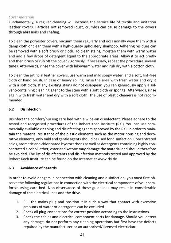
6.3 Avoidance of hazards
In order to avoid dangers in connection with cleaning and disinfection, you must first ob-serve the following regulations in connection with the electrical components of your com-fort/nursing care bed. Non-observance of these guidelines may result in considerable damage of the electrical lines and the drive.
1. Pull the mains plug and position it in such a way that contact with excessive amounts of water or detergents can be excluded.
2. Check all plug-connections for correct position according to the instructions. 3. Check the cables and electrical component parts for damage. Should you detect
any damage, do not perform any cleaning operations but first have the defects repaired by the manufacturer or an authorised/ licensed electrician.

42
4. Before starting the operation, check the mains plug for residual moisture and dry or blow out the device, if necessary.
5. On any suspicion of the intrusion of moisture into the electrical components, dis-connect the mains plug immediately and do not re-establish the connection. Put the comfort/nursing care bed out of operation immediately, attach an appropri-ate visible label and contact the operator.
Hazard note from Bock Use of abrasive cleansers and/or detergents containing grinding particles, cleaning pads or stain-less steel cleaners for the cleaning is absolutely not recommended. Neither use organic solvents such as halogenated/aromatic hydrocarbons and ketones nor detergents containing acid or al-kaline. Never clean the comfort/nursing care bed using a water hose or high-pressure cleaner as this might lead to the intrusion of fluid into the electrical component parts, which could then cause malfunctions and hazards. The comfort / nursing care bed must be cleaned and disinfected before each use. Also, at the same time, perform a visual inspection to check for any mechanical damages. You will find de-tailed information on this in the inspection list.
43
7 Guidance and manufacturer's declaration
Guidance and manufacturer's declaration
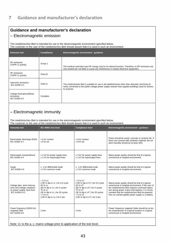
– Electromagnetic emission
The medizinisches Bett is intended for use in the electromagnetic environment specified below. The customer or the user of the medizinisches Bett should assure that it is used in such an environment.
Emission test Complliance Electromagnetic environment - guidance
RF emissions CISPR 11 (partly)
Group 1
The medical used bed uses RF energy only for its internal function. Therefore, its RF emissions are very lowand are not likely to cause any interference in nearby electronic equipment.
RF emissions CISPR 11 (partly)
Class B
The medizinisches Bett is suitable for use in all establishments other than domestic and those di-rectly connected to the public-voltage power supply network that supplies buildings used for domes-tic purpose.
Harmonic emissions IEC 61000-3-2
Class A
Voltage fluctuations/flicker emissions IEC 61000-3-3
Complies
– Electromagnetic immunity
The medizinisches Bett is intended for use in the electromagnetic environment specified below. The customer or the user of the medizinisches Bett should assure that it is used in such an environment.
Immunity test IEC 60601 test level Compliance level Electromagnetic environment - guidance
Electrostatic discharge (ESD) IEC 61000-4-2
± 6 kV contact ± 8 kV air
± 6 kV contact ± 8 kV air
Floors should be wood, concrete or ceramic tile. If floors are covered with synthetic material, the rel-ative humidity should be at least 30%.
Electrostatic transient/burst IEC 61000-4-4
± 2 kV for power supply lines ± 1 kV for input/output lines
± 2 kV for power supply lines ± 1 kV for input/output lines
Mains power quality should be that of a typical commercial or hospital environment.
Surge IEC 61000-4-5
± 1 kV differential mode ± 2 kV common mode
± 1 kV differential mode ± 2 kV common mode
Mains power quality should be that of a typical commercial or hospital environment.
Voltage dips, short interrup-tions and voltage variations on power supply input lines IEC 61000-4-11
< 5 % UT (>95 % dip in UT ) for 0.5 cycle 40 % UT (60 % dip in UT ) for 5 cycles 70 % UT (30 % dip in UT ) for 25 cycles < 5 % UT (>95 % dip in UT ) for 5 sec
< 5 % UT (>95 % dip in UT ) for 0.5 cycle 40 % UT (60 % dip in UT ) for 5 cycles 70 % UT (30 % dip in UT ) for 25 cycles < 5 % UT (>95 % dip in UT ) for 5 sec
Mains power quality should be that of a typical commercial or hospital environment. If the user of the medizinisches Bett requires continued opera-tion during power mains interruptions, it is recom-mended that the medizinisches Bett be powered from an uninterruptible power supply or a battery.
Power frequency (50/60 Hz) magnetic field IEC 61000-4-8
3 A/m 3 A/m Power frequency magnetic fields should be at lev-els characteristic of a typical location in a typical commercial or hospital environment.
Note: UT is the a. c. mains voltage prior to application of the test level.
44
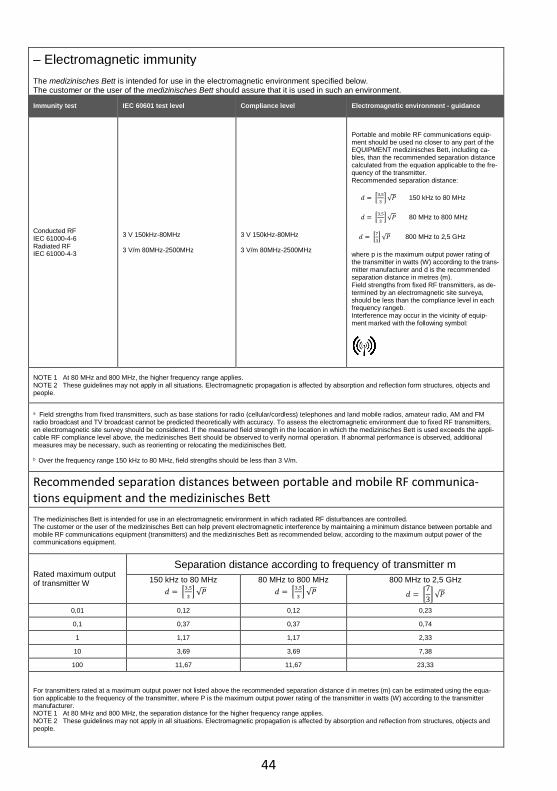
– Electromagnetic immunity
The medizinisches Bett is intended for use in the electromagnetic environment specified below. The customer or the user of the medizinisches Bett should assure that it is used in such an environment.
Immunity test IEC 60601 test level Compliance level Electromagnetic environment - guidance
Conducted RF IEC 61000-4-6 Radiated RF IEC 61000-4-3
3 V 150kHz-80MHz ……………………………………… 3 V/m 80MHz-2500MHz
3 V 150kHz-80MHz …………………………………… 3 V/m 80MHz-2500MHz
Portable and mobile RF communications equip-ment should be used no closer to any part of the EQUIPMENT medizinisches Bett, including ca-bles, than the recommended separation distance calculated from the equation applicable to the fre-quency of the transmitter. Recommended separation distance:
𝑑 = [3,5
3] √𝑃 150 kHz to 80 MHz
𝑑 = [3,5
3] √𝑃 80 MHz to 800 MHz
𝑑 = [7
3] √𝑃 800 MHz to 2,5 GHz
where p is the maximum output power rating of the transmitter in watts (W) according to the trans-mitter manufacturer and d is the recommended separation distance in metres (m). Field strengths from fixed RF transmitters, as de-termined by an electromagnetic site surveya, should be less than the compliance level in each frequency rangeb. Interference may occur in the vicinity of equip-ment marked with the following symbol:
NOTE 1 At 80 MHz and 800 MHz, the higher frequency range applies. NOTE 2 These guidelines may not apply in all situations. Electromagnetic propagation is affected by absorption and reflection form structures, objects and people.
a Field strengths from fixed transmitters, such as base stations for radio (cellular/cordless) telephones and land mobile radios, amateur radio, AM and FM radio broadcast and TV broadcast cannot be predicted theoretically with accuracy. To assess the electromagnetic environment due to fixed RF transmitters, en electromagnetic site survey should be considered. If the measured field strength in the location in which the medizinisches Bett is used exceeds the appli-cable RF compliance level above, the medizinisches Bett should be observed to verify normal operation. If abnormal performance is observed, additional measures may be necessary, such as reorienting or relocating the medizinisches Bett. b Over the frequency range 150 kHz to 80 MHz, field strengths should be less than 3 V/m.
Recommended separation distances between portable and mobile RF communica-tions equipment and the medizinisches Bett
The medizinisches Bett is intended for use in an electromagnetic environment in which radiated RF disturbances are controlled. The customer or the user of the medizinisches Bett can help prevent electromagnetic interference by maintaining a minimum distance between portable and mobile RF communications equipment (transmitters) and the medizinisches Bett as recommended below, according to the maximum output power of the communications equipment.
Rated maximum output of transmitter W
Separation distance according to frequency of transmitter m
150 kHz to 80 MHz
𝑑 = [3,5
3] √𝑃
80 MHz to 800 MHz
𝑑 = [3,5
3] √𝑃
800 MHz to 2,5 GHz
𝑑 = [7
3] √𝑃
0,01 0,12 0,12 0,23
0,1 0,37 0,37 0,74
1 1,17 1,17 2,33
10 3,69 3,69 7,38
100 11,67 11,67 23,33
For transmitters rated at a maximum output power not listed above the recommended separation distance d in metres (m) can be estimated using the equa-tion applicable to the frequency of the transmitter, where P is the maximum output power rating of the transmitter in watts (W) according to the transmitter manufacturer. NOTE 1 At 80 MHz and 800 MHz, the separation distance for the higher frequency range applies. NOTE 2 These guidelines may not apply in all situations. Electromagnetic propagation is affected by absorption and reflection from structures, objects and people.

45
8 Regular inspections with service
Regular inspections facilitate the maintaining of the highest possible safety level, and are considered to be an important safety precaution. Medical devices must be inspected reg-ularly in terms of safety according to the stipulated regulations of the manufacturer and the generally accepted rules of technology. The safety-related protection measures are subject to different requirements and demands. This also applies to the potential wear and tear in the daily use. To prevent such risks, constant and consistent compliance with the deadlines for regular functional testing is absolutely necessary. The manufacturer has no influence on the operator’s adherence with respect to the observance of these regula-tions concerning electric beds. Bock facilitates the observance of the necessary precau-tionary measures to be taken by means of their time-saving services.
The execution of the inspection, assessment and documentation must be performed only by or under supervision of professional persons such as electricians or electro-technically instructed persons who have a thorough knowledge of the relevant provisions and are able to recognize possible impacts and hazards.
In the event that no person on the part of the user is eligible for the regular inspections or is commissioned, the Bock service offers you the assumption of the regular inspections with simultaneous control and observance of the corresponding intervals for a fee.
The company Hermann Bock GmbH specifies an inspection interval which stipulates that a safety-technical inspection is to be executed at least once annually, and with each re-use of the bed.
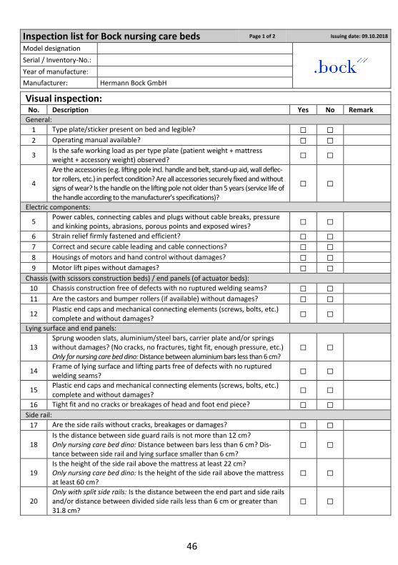
For support purposes, Hermann Bock GmbH will provide you with the inspection list in the assembly and operation manual for carrying out all the necessary tests. Please copy the checklist as a form for your inspection. The checklist serves as evidence report of the per-formed inspection and must be kept on file.
The inspection list can also be downloaded from the Internet: www.bock.net.
Attention: Unauthorised technical changes to the product voids all warranty claims.
46
Inspection list for Bock nursing care beds Page 1 of 2 Issuing date: 09.10.2018 Model designation
Serial / Inventory-No.: Year of manufacture:
Manufacturer: Hermann Bock GmbH
Visual inspection:
No. Description Yes No Remark
General:
1 Type plate/sticker present on bed and legible? ☐ ☐
2 Operating manual available? ☐ ☐
3 Is the safe working load as per type plate (patient weight + mattress weight + accessory weight) observed?
☐ ☐
4
Are the accessories (e.g. lifting pole incl. handle and belt, stand-up aid, wall deflec-tor rollers, etc.) in perfect condition? Are all accessories securely fixed and without signs of wear? Is the handle on the lifting pole not older than 5 years (service life of the handle according to the manufacturer's specifications)?
☐ ☐
Electric components:
5 Power cables, connecting cables and plugs without cable breaks, pressure and kinking points, abrasions, porous points and exposed wires?
☐ ☐
6 Strain relief firmly fastened and efficient? ☐ ☐
7 Correct and secure cable leading and cable connections? ☐ ☐
8 Housings of motors and hand control without damages? ☐ ☐
9 Motor lift pipes without damages? ☐ ☐
Chassis (with scissors construction beds) / end panels (of actuator beds):
10 Chassis construction free of defects with no ruptured welding seams? ☐ ☐
11 Are the castors and bumper rollers (if available) without damages? ☐ ☐
12 Plastic end caps and mechanical connecting elements (screws, bolts, etc.) complete and without damages?
☐ ☐
Lying surface and end panels:
13 Sprung wooden slats, aluminium/steel bars, carrier plate and/or springs without damages? (No cracks, no fractures, tight fit, enough pressure, etc.) Only for nursing care bed dino: Distance between aluminium bars less than 6 cm?
☐ ☐
14 Frame of lying surface and lifting parts free of defects with no ruptured welding seams?
☐ ☐
15 Plastic end caps and mechanical connecting elements (screws, bolts, etc.) complete and without damages?
☐ ☐
16 Tight fit and no cracks or breakages of head and foot end piece? ☐ ☐
Side rail:
17 Are the side rails without cracks, breakages or damages? ☐ ☐
18 Is the distance between side guard rails is not more than 12 cm? Only nursing care bed dino: Distance between bars less than 6 cm? Dis-tance between side rail and lying surface smaller than 6 cm?
☐ ☐
19 Is the height of the side rail above the mattress at least 22 cm? Only nursing care bed dino: Is the height of the side rail above the mattress at least 60 cm?
☐ ☐
20 Only with split side rails: Is the distance between the end part and side rails and/or distance between divided side rails less than 6 cm or greater than 31.8 cm?
☐ ☐

47
Inspection list for Bock nursing care beds Page 2 of 2 Issuing date: 09.10.2018 Name / location:
Address / Postcode / City: Station / Room:
Name of examiner / Date:
Functional testing:
No. Description Yes No Remark
Side rail:
21 Are the side rails running smoothly in the tracks and locking into place safely? Only nursing care bed dino: Smooth running of the doors on the aluminium profiles? Doors lock securely into the locking mechanism?
☐ ☐
22 Are the side guard rails/parts sufficiently mounted and firmly seated? ☐ ☐
23 Was the load stress test of the side rail without deformation? ☐ ☐
Lying surface:
24 Back part, leg part adjustment and special functions properly and without any obstacles?
☐ ☐
25 Safe grid mechanism of lower leg rest (if available) in every step, even un-der stress?
☐ ☐
26 Only domiflex 2 nursing care bed: Is the clamping effect of the 6 eccentric clamps sufficient? If this is not the case, the stop nut must be tightened slightly!
☐ ☐
Chassis (with scissors construction beds) / end panels (of actuator beds):
27 Hub adjustment properly and without any obstacles? ☐ ☐
28 Safe braking effect, blocking and free running of wheels? ☐ ☐
Electric components:
29 Testing of hand control (keys and disabling function) all working properly without any defects?
☐ ☐
30 Battery/Bock battery/emergency lowering: Function properly and without any defects?
☐ ☐
General:
31 Function of the accessories flawless and safe? (e.g. lifting pole incl. grab handle and belt, stand-up aids, wall deflector holder, etc.)
☐ ☐
Electric measuring:
No. Description Yes No Remark
Insulation resistance - (must be only measured on old models before manufacture year of 2002.)
32 Insulation resistance – measured value larger than 7 MΩ? ☐ ☐
Device leakage current - (This measurement does not have to be carried out for nursing care beds with a limoss drive set for nursing care beds manufactured from 2018-05 onwards, or for nursing care beds with a Dewert drive set for nursing care beds manufactured from 2015-07 onwards during the first 10 years of service life, if the visual and functional testing is passed, if this is a nursing care bed with a limoss or Dewert switched-mode power supply (SMPS). With these nursing care beds, the mains voltage is directly converted into a safety extra-low voltage of max. 35 V in the switch-mode power supply unit.)
33 Device leakage current - measured value smaller than 0.1mA? ☐ ☐
Evaluation
No. Description Yes No Remark
34 All values/inspection within the permissible range passed? ☐ ☐
In the event the inspection result did not pass: ☐Repair
☐Singling out
Date / Signature Next inspection

Our SALES PARTNERS Our business partners pursue the same strategy as we do: quality, innovation and above-average standards that are internationally recognized. You can rely on our business partners as you can rely on us. Please note that only our authorised personnel and our sales partners can provide training, supply of spare parts, repairs, inspections and other service. Otherwise, all warranty claims will be void. A listing of our current distributors can be found under www.bock.net/kontakt/vertriebspartner
© registered trademark 890.02256 current as of: 2020-04 Rev. 01 Technical changes reserved
Hermann Bock GmbH Nickelstr. 12 D-33415 Verl, Germany
Tel.: +49 52 46 92 05 - 0 Fax: +49 52 46 92 05 - 25 Internet: www.bock.net E-Mail: [email protected]