Combustion Dynamics in a High Aspect Ratio...
7
917 Proceedings of the Combustion Institute, Volume 29, 2002/pp. 917–923 COMBUSTION DYNAMICS IN A HIGH ASPECT RATIO ENGINE M. KIRTAS, M. DISSEAU, D. SCARBOROUGH, J. JAGODA and S. MENON School of Aerospace Engineering Georgia Institute of Technology Atlanta, GA 30332-0150, USA A large eddy simulation (LES) based design tool for modeling rectangular cross-section, high aspect ratio (AR) combustors has been developed and tested against experimental results. The combustor is part of a miniature power generator in which a free piston fitted with permanent magnets is oscillated by the out-of-phase heat release from two opposed high AR combustors. This device is placed inside a permanent magnetic coil, where the piston motion generates electric power. The combustor geometry is governed by the desire to mass-produce the device using microelectromechanical systems (MEMS) techniques. Since ignition, flame propagation, heat losses, and quenching have been shown to be seriously affected by this combustor’s geometry, standard design tools developed for low AR engines can not be used for these devices. Instead, LES methodology has been developed to address this. A wall heat transfer model is used for effectively handling the intense heat transfer in the system. The piston motion is treated by a Cartesian grid scheme. A miniaturized, high AR power generator in which the piston is moved by a single combustor and a spring was designed and built. The LES model provided significant guidance for the location of the inlet and exhaust ports during the design process. Comparison of the experimental results and predictions shows that flame behavior is well captured by the model, as are wall and exhaust temperatures. However, because mass losses between piston and cylinder were neglected and because the use of global kinetics did not permit the proper treatment of wall quenching, the model tends to overpredict both pressure pulse frequency and amplitude, as well as work generated by the device. A more sophisticated treatment of combustion chemistry is expected to improve agreement between experimental results and the model. Introduction In combustion-based power applications, power obtained from the thermodynamic cycle depends, in part, on the combustor geometry. Most conventional engines employ small aspect ratio (AR) combustors (here, the AR is defined as the ratio of surface area to volume), with AR in the 3–5 range. Recently, high-efficiency, small-scale engines with high power density and long life have been developed for dif- ferent uses, such as mobile soldier power packs. Such combustors are generally rectangular and flat (i.e., have large AR) because this makes them ulti- mately amenable to microelectromechanical systems (MEMS) fabrication techniques. However, devel- opment of such new devices requires a major over- haul of design methods used for small AR systems [1]. For example, in these devices, near-wall com- bustion is much more critical than in low AR com- bustors, which leads to significant heat losses and local quenching. The importance of wall quenching has been noted in many previous investigations [2,3]. In the present study, a small-scale, high AR, free- piston engine is investigated using a combined ex- perimental-numerical approach. In such a device, thermal energy (from combustion) is converted to mechanical energy to set a piston into cyclic motion. Large-scale, low AR, free-piston engines are well known and have been successfully deployed in the past [4]. Obtaining pneumatic, hydraulic, or electri- cal energy with single, opposed, or dual piston ar- rangements is possible [5,6]. The present study, however, focuses on a very small scale device with a very high AR. The issues involved in the construc- tion of this device are discussed, followed by a de- scription of its performance. Due to its small scale, it is nearly impossible to carry out in situ measure- ments in this combustor. Therefore, numerical sim- ulations are carried out to understand the combus- tion dynamics in these devices and also to provide guidelines for design optimization. The Experimental Engine The ultimate concept of the power generator, shown schematically in Fig. 1, consists of a free pis- ton that is set into sustained oscillation by out-of- phase heat release in two opposed high AR com- bustors. This device is placed inside a permanent magnetic coil, where the motion of the piston leads to electric power generation [7]. Since most of the combustion takes place in near-constant volume, ini- tial work concentrated on ignition and flame prop- agation in high AR chambers (with spanwise dimen- sions of 12, 6.35, and 3.125 mm) with no moving
Transcript of Combustion Dynamics in a High Aspect Ratio...

917
Proceedings of the Combustion Institute, Volume 29, 2002/pp. 917–923
COMBUSTION DYNAMICS IN A HIGH ASPECT RATIO ENGINE
M. KIRTAS, M. DISSEAU, D. SCARBOROUGH, J. JAGODA and S. MENONSchool of Aerospace EngineeringGeorgia Institute of TechnologyAtlanta, GA 30332-0150, USA
A large eddy simulation (LES) based design tool for modeling rectangular cross-section, high aspectratio (AR) combustors has been developed and tested against experimental results. The combustor is partof a miniature power generator in which a free piston fitted with permanent magnets is oscillated by theout-of-phase heat release from two opposed high AR combustors. This device is placed inside a permanentmagnetic coil, where the piston motion generates electric power. The combustor geometry is governed bythe desire to mass-produce the device using microelectromechanical systems (MEMS) techniques. Sinceignition, flame propagation, heat losses, and quenching have been shown to be seriously affected by thiscombustor’s geometry, standard design tools developed for low AR engines can not be used for thesedevices. Instead, LES methodology has been developed to address this. A wall heat transfer model is usedfor effectively handling the intense heat transfer in the system. The piston motion is treated by a Cartesiangrid scheme. A miniaturized, high AR power generator in which the piston is moved by a single combustorand a spring was designed and built. The LES model provided significant guidance for the location of theinlet and exhaust ports during the design process. Comparison of the experimental results and predictionsshows that flame behavior is well captured by the model, as are wall and exhaust temperatures. However,because mass losses between piston and cylinder were neglected and because the use of global kineticsdid not permit the proper treatment of wall quenching, the model tends to overpredict both pressure pulsefrequency and amplitude, as well as work generated by the device. A more sophisticated treatment ofcombustion chemistry is expected to improve agreement between experimental results and the model.
Introduction
In combustion-based power applications, powerobtained from the thermodynamic cycle depends, inpart, on the combustor geometry. Most conventionalengines employ small aspect ratio (AR) combustors(here, the AR is defined as the ratio of surface areato volume), with AR in the 3–5 range. Recently,high-efficiency, small-scale engines with high powerdensity and long life have been developed for dif-ferent uses, such as mobile soldier power packs.Such combustors are generally rectangular and flat(i.e., have large AR) because this makes them ulti-mately amenable to microelectromechanical systems(MEMS) fabrication techniques. However, devel-opment of such new devices requires a major over-haul of design methods used for small AR systems[1]. For example, in these devices, near-wall com-bustion is much more critical than in low AR com-bustors, which leads to significant heat losses andlocal quenching. The importance of wall quenchinghas been noted in many previous investigations [2,3].
In the present study, a small-scale, high AR, free-piston engine is investigated using a combined ex-perimental-numerical approach. In such a device,thermal energy (from combustion) is converted to
mechanical energy to set a piston into cyclic motion.Large-scale, low AR, free-piston engines are wellknown and have been successfully deployed in thepast [4]. Obtaining pneumatic, hydraulic, or electri-cal energy with single, opposed, or dual piston ar-rangements is possible [5,6]. The present study,however, focuses on a very small scale device with avery high AR. The issues involved in the construc-tion of this device are discussed, followed by a de-scription of its performance. Due to its small scale,it is nearly impossible to carry out in situ measure-ments in this combustor. Therefore, numerical sim-ulations are carried out to understand the combus-tion dynamics in these devices and also to provideguidelines for design optimization.
The Experimental EngineThe ultimate concept of the power generator,
shown schematically in Fig. 1, consists of a free pis-ton that is set into sustained oscillation by out-of-phase heat release in two opposed high AR com-bustors. This device is placed inside a permanentmagnetic coil, where the motion of the piston leadsto electric power generation [7]. Since most of thecombustion takes place in near-constant volume, ini-tial work concentrated on ignition and flame prop-agation in high AR chambers (with spanwise dimen-sions of 12, 6.35, and 3.125 mm) with no moving

918 NEW CONCEPTS IN COMBUSTION TECHNOLOGY—Micro-Power Generation
Fig. 1. Schematic of a dual-combustor power generator.Also shown is the magnetic array.
Fig. 2. Schematics showing various inlet (arrows in) andexhaust (arrow out) port configurations. Numbers (1–4) re-fer to design cases. Ports are valved by piston.
Fig. 3. Predicted variations in maximum percentage offresh reactants in the combustion chamber during each cy-cle with time over many cycles. Number (1–4) in the insetrefer to port configurations in Fig. 2.
parts. Heat transfer through and radical removal atthe walls were identified both experimentally andnumerically as a major cause for the limited pressurerise following combustion in the chamber [8]. Sub-sequently, a preliminary, high AR free-piston enginewith a moving piston between two combustionchambers was built.
Figure 2 (1) shows schematically the initial loca-tions of the inlet and exhaust. However, sustainedoscillations could not be maintained in this device.Since detailed measurements were difficult to makein such a narrow chamber, large eddy simulations(LES) were carried out for this and other variants ofthis configuration (Fig. 2, 1–4). Results showed thatinlet/outlet port locations, and thus injection andscavenging strategies, all influenced the perfor-mance of the device. In particular, it was determinedthat for the unsuccessful designs, the scavenging ofthe burned products from the chamber was not suf-ficiently efficient, resulting in a reduction in quantityof reactants introduced into the combustor duringconsecutive cycles. Fig. 3 shows the calculated re-actant concentration in the chamber as a function oftime for the various designs. It can be seen that tomaintain constant-frequency oscillations, the reac-tant concentration at the start of the cycle mustreach 90%. At lower concentrations, the combustionefficiency and pressure rise drop from cycle to cycle,leading eventually to total failure.
The above represents one of the few exampleswhere LES has played a direct role in engineeringdesign by providing guidelines for design improve-ments. Because of the difficulty of carrying out de-tailed, in situ measurements, LES may prove to bethe only cost-effective means for design optimizationbefore actual fabrication. The present effort is,therefore, directed toward developing and establish-ing such a design capability.
Aided by the LES studies, a research engine hasbeen built to study the dynamics of cyclic combus-tion. This device consists of a single combustor-spring configuration (Fig. 4). A piston made of castiron moves in a flat steel cylinder with optical accessthrough Pyrex windows. The piston motion valvesthe inlet and exhaust ports and also triggers an ig-nition spark (approximately 200 mJ across 2 mm inless than 300 ls) generated by an automotive igni-tion circuit. To limit leaks, a dynamic wiper sealmade of a double layer of Teflon-coated fiberglass isused along the longer sides. A split piston (whosetwo halves are pushed against the sidewalls by aspring) seals along the sidewalls while leaving a gapin its center, which is itself sealed by the dynamicfrontal seal. Sealing is further improved using Di-ester synthetic oil.
To start the engine, the piston is pulled backagainst the spring using a handle. This opens theinlet and exhaust ports and allows the combustionchamber to fill with fresh propane/air mixture,

HIGH ASPECT RATIO ENGINE 919
which is injected at an angle. When the handle isreleased, the spring propels the piston forward.Once the ports close, the mixture is compressed andthen ignited by the spark. The subsequent pressureincrease decelerates and eventually reverses the pis-ton’s motion. Eventually, the ports reopen, the com-bustion products exhaust, and fresh reactants enterthe chamber. The spring is compressed until the pis-ton motion is reversed and the cycle restarts.
Pressure is measured using an Endevco 8541-100piezoresistive transducer, and piston position is re-corded with a Micro-Epsilon non-contact optical dis-placement monitor. These two measurements (un-der load) are combined to determine the mechanicalpower generated by the device using a pressure-vol-ume (P-V) diagram. Optimum operating conditionsare determined by monitoring a real-time plot of P-V(with LABView) while changing spark timing, mix-ture ratio, and injection direction to maximize me-chanical power output. Electrical power output isdetermined by connecting a voice coil generatorsubwoofer, without the cone, run as a generator tothe piston and measuring the resultant voltage acrossa known resistance. Wall and exhaust flow tempera-tures are measured with type K thermocouples. Theflame is observed directly by recording spontaneousradical emission using a Kodak Ektapro digital in-tensified camera at 3000 fps. Shadowgraphy is usedto visualize the flow by recording the motion of thedensity gradients.
The Computational Engine
Numerical studies of this device are also con-ducted. Identical dimensions and conditions areused wherever possible. There are some inevitablesimplifications needed to model the experimental
device. For example, leakage around the piston (ob-served in experiments) is not included, friction is ne-glected, ignition is approximated as volume sources(i.e., the spark is not modeled), and simple one-stepglobal kinetics is used for premixed propane/aircombustion [9]. Future studies will attempt to in-clude mass leakage effect and will employ a moredetailed kinetics mechanism using in-situ adaptivetabulation (ISAT) [10]. However, the current ap-proximations do not impact the overall dynamics, asshown below.
The flow field in the combustor evolves cyclicallyas the piston oscillates. Therefore, turbulent mixing,combustion, heat release, volumetric expansion, andpiston motion all occur synchronously and must beresolved accurately in space and time in order tocapture the dynamics. Steady-state or even unsteadyReynolds-averaged Navier-Stokes methods are notlikely to capture the highly non-homogeneous mix-ing and flame-flow interactions, and direct simula-tions are prohibitively expensive. Here, we employthe LES method in which all spatial scales largerthan the grid are resolved in a time-accurate manner.The effect of scales smaller than the grid on the re-solved motion is modeled using a subgrid model.The LES equations for a compressible, chemicallyreacting flow are described elsewhere [11] andtherefore avoided here for brevity. The closure ofthe unresolved subgrid terms is achieved using aneddy viscosity model that is parametrized using thegrid scale and the subgrid kinetics energy, ksgs. Thelatter is obtained by solving a one-equation transportmodel which is reported elsewhere [11] and there-fore not repeated here.
The closure of the mean reaction rate is obtainedby employing a modified eddy-breakup (EBU)model [12] which determines the filtered reactionrate as the minimum of the inverse of a turbulentmixing time (obtained using ksgs) and the Arrheniusrate.
The LES equations are solved using an explicitfinite-volume scheme that is second-order accuratein both space and time. No-slip boundary conditionsare applied for velocity components on walls. Heatflux through the walls is included by solving the un-steady heat equation, (1/�)(�T/�t) � (�2T/�n2), per-pendicular to the respective walls, where n is thewall normal direction. Neumann conditions are em-ployed for the wall heat fluxes, such that q� �
� T�) and qf � � Tf), respectively.h (T h (T� w f w� fThe subscripts � and ‘‘f’’ denote ambient and com-bustor sides of the wall. In this formulation, h� andhf are the convective heat transfer coefficients to airand combustor sides of the slab, respectively, and �is the thermal diffusivity of the solid wall. The gas-phase temperature close to the wall, Tf, is knownfrom the gas-phase solution, and T� is set to 300 K.Finally, Twf and are the wall temperatures on theTw�
gas and ambient sides of the wall, respectively, andare obtained as part of the solution. The problem of
Fig. 4. Schematic of the combustor-spring configurationengine used in this investigation. All dimensions are in mil-limeters. Injection and exhaust ports are 3.175 � 12.7 mm,and their centers are located 31.75 mm from top dead cen-ter (TDC). Also shown are the injection tube (a), the pres-sure transducer (b), and the spark plug (c).
920 NEW CONCEPTS IN COMBUSTION TECHNOLOGY—Micro-Power Generation
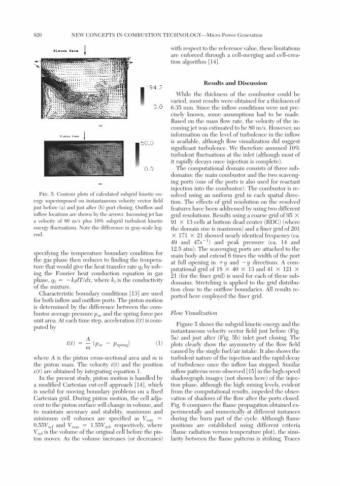
Fig. 5. Contour plots of calculated subgrid kinetic en-ergy superimposed on instantaneous velocity vector fieldjust before (a) and just after (b) port closing. Outflow andinflow locations are shown by the arrows. Incoming jet hasa velocity of 80 m/s plus 10% subgrid turbulent kineticenergy fluctuations. Note the difference in gray-scale leg-end.
specifying the temperature boundary condition forthe gas phase then reduces to finding the tempera-ture that would give the heat transfer rate qf by solv-ing the Fourier heat conduction equation in gasphase, qf � �kfdT/dx, where kf is the conductivityof the mixture.
Characteristic boundary conditions [13] are usedfor both inflow and outflow ports. The piston motionis determined by the difference between the com-bustor average pressure pav and the spring force perunit area. At each time step, acceleration x(t) is com-puted by
Ax(t) � (p � p ) (1)av springm
where A is the piston cross-sectional area and m isthe piston mass. The velocity x(t) and the positionx(t) are obtained by integrating equation 1.
In the present study, piston motion is handled bya modified Cartesian cut-cell approach [14], whichis useful for moving boundary problems on a fixedCartesian grid. During piston motion, the cell adja-cent to the piston surface will change in volume, andto maintain accuracy and stability, maximum andminimum cell volumes are specified as Vmin �0.55Vref and Vmax � 1.55Vref, respectively, whereVref is the volume of the original cell before the pis-ton moves. As the volume increases (or decreases)
with respect to the reference value, these limitationsare enforced through a cell-merging and cell-crea-tion algorithm [14].
Results and Discussion
While the thickness of the combustor could bevaried, most results were obtained for a thickness of6.35 mm. Since the inflow conditions were not pre-cisely known, some assumptions had to be made.Based on the mass flow rate, the velocity of the in-coming jet was estimated to be 80 m/s. However, noinformation on the level of turbulence in the inflowis available, although flow visualization did suggestsignificant turbulence. We therefore assumed 10%turbulent fluctuations at the inlet (although most ofit rapidly decays once injection is complete).
The computational domain consists of three sub-domains: the main combustor and the two scaveng-ing ports (one of the ports is also used for reactantinjection into the combustor). The combustor is re-solved using an uniform grid in each spatial direc-tion. The effects of grid resolution on the resolvedfeatures have been addressed by using two differentgrid resolutions. Results using a coarse grid of 95 �91 � 13 cells at bottom dead center (BDC) (wherethe domain size is maximum) and a finer grid of 201� 171 � 21 showed nearly identical frequency (ca.49 and 47s�1) and peak pressure (ca. 14 and12.5 atm). The scavenging ports are attached to themain body and extend 6 times the width of the portat full opening in �y and �y directions. A com-putational grid of 18 � 40 � 13 and 41 � 121 �21 (for the finer grid) is used for each of these sub-domains. Stretching is applied to the grid distribu-tion close to the outflow boundaries. All results re-ported here employed the finer grid.
Flow Visualization
Figure 5 shows the subgrid kinetic energy and theinstantaneous velocity vector field just before (Fig.5a) and just after (Fig. 5b) inlet port closing. Theplots clearly show the asymmetry of the flow fieldcaused by the single fuel/air intake. It also shows theturbulent nature of the injection and the rapid decayof turbulence once the inflow has stopped. Similarinflow patterns were observed [15] in the high-speedshadowgraph images (not shown here) of the injec-tion phase, although the high mixing levels, evidentfrom the computational results, impeded the obser-vation of shadows of the flow after the ports closed.Fig. 6 compares the flame propagation obtained ex-perimentally and numerically at different instancesduring the burn part of the cycle. Although flamepositions are established using different criteria(flame radiation versus temperature plot), the simi-larity between the flame patterns is striking. Traces

HIGH ASPECT RATIO ENGINE 921
Fig. 6. Comparison of flame propagation as indicated by radical radiation for experimental (a) and temperaturedistribution for computational (b) study. Images are 0.33 ms and 0.3 ms apart in (a) and (b), respectively.
Fig. 7. Comparison of pressure-time histories for ex-periment (symbol) and computations for model deter-mined (dashed line) and prescribed (solid line) piston mo-tion. The former shows an overprediction of amplitude andfrequency by 10%. In the latter, the overprediction is lim-ited to amplitudes.
of large-scale motion, leftover from the flow patterngenerated by the injection, are visible in the large-scale propagation pattern of the flame. The presenceof the large-scale motion, which is usually not seenin conventional engines, is attributed to the relativelylow precompression of this design and the high ARgeometry. Small-scale turbulence is also present andevident by the wrinkled edges of the flame.
Performance of the Engine
In much of the work presented here, the pistonmotion is determined by the model. However, runswere carried out for selected conditions where themeasured displacement history of the piston wasprescribed for the model. In Fig. 7, the pressuresignature in the chamber is shown for experimental
results and both the LESs. Although direct compar-ison is not possible or intended (due to differencesin ignition techniques, kinetics model, and leakage,as noted earlier), the general trends are in very goodqualitative agreement. Both studies show that cycliccombustion with repeatable pressure peaks isachieved at a fixed frequency. However, the modeloverpredicts both frequency and amplitude by ap-proximately 10% when the piston motion is calcu-lated, pressure amplitude only when the piston mo-tion is prescribed. Estimates of the mass lossesaround the piston suggest that about half of the re-duction in pressure amplitude is due to mass losses,with the remainder caused by neglecting wallquenching.
These discrepancies are understandable consid-ering the approximations used in the model. To com-pensate for these assumptions, a spring constant(2000 N/m) nearly twice that used in the experi-ments was used in the model. This was based onearlier findings [7] that suggest that adjusting thespring constant can, at least partially, compensate forneglecting mass loss, spark ignition, and kernelgrowth and for using simple kinetics, all of whichimpact frequency and amplitude. Future studies willinclude more detailed kinetics (needed to allow forlocal extinction/reignition and near-wall quenchingin high AR combustors) using ISAT [10] to relaxsome of these approximations.
Closer inspection of Fig. 7 shows how the pressuredevelops through the ignition and scavengingphases. Since no mass loss is included, the predictedpeak pressure is higher than that measured in spiteof the adjusted spring constant (see above). Also, theinitial pressure rises faster in the simulation. Thepressure decay during the final stages of the exhauststroke is also faster. In the experiments, pressure de-creases almost linearly, showing the effects of bothmass loss and blowout through the port, whereas inLES the pressure drops more rapidly once the portopens.

922 NEW CONCEPTS IN COMBUSTION TECHNOLOGY—Micro-Power Generation
Fig. 8. P-V diagram showing measured (symbol) andpredicted work (averaged over multiple cycles). Work isoverpredicted in computed cases for both model deter-mined (solid line) and prescribed piston motion (dashedline), since mass losses and wall quenching are neglected.
The performance of the engine can be quantifiedusing a pressure-volume diagram, as shown in Fig.8, where integrating the area in the cycle indicatesthe mechanical work produced. Both when the pis-ton motion is determined by the model and when itis prescribed, the predicted work output is largerthan that measured experimentally. This could bedue not only to mass losses that are not modeled,but also to the filtered reaction rate and the simpleEBU model that provided closure. Future studieswill include a subgrid mixing and combustion model[16]. Furthermore, more detailed kinetics will allowprediction of extinction and near-wall quenching.Nevertheless, the current predictions do show thatthe qualitative behavior and trends of cyclic com-bustion are in good agreement with observations.
Figure 8 shows that the P-V diagram agrees betterwith the experimental results when the motion ofthe piston is prescribed than when it is calculated bythe model. This occurs because in the latter caseerrors accumulate from cycle to cycle.
Temperatures were measured on the glass side-walls of the combustor and in its exhaust. Becauseof the relatively high frequency of heat release andthe large mass of the wall, the wall temperaturereaches a steady-state value. The exhaust tempera-tures were averaged over a number of cycles. Exte-rior wall temperatures were measured at the centerof that part of the wall exposed to the combustionchamber when the piston has reached TDC. Addi-tional temperatures were measured 2 cm in the �yand �y directions. The wall temperature at the cen-ter was measured to be 418 K, while those off centerwere about 35� lower. The predicted wall tempera-tures were approximately 65� higher than those mea-sured, with temperatures near the exhaust beingabout 15� higher than those near the inlet. The pre-dicted exhaust temperatures were closer to those
measured: 433 versus 407 K, respectively. The pre-dicted temperatures are probably too high becausewall quenching [3] is not accounted for in the pres-ent model. That also explains why this effect is morepronounced at the wall than in the exhaust.
Conclusions
LES-based design tool for predicting the perfor-mance of small, high AR combustors of rectangularcross section was developed. Its predictions werethen compared with experimental results obtainedin a corresponding combustion chamber, whichforms a part of a miniature power generator. Themodel predicted the periodic motion of the pistonand the resulting pressure variations in the chamber,although the frequency and amplitude of the pres-sure fluctuations were overpredicted by about 10%.Half of this overestimate is caused by neglected masslosses past the piston, while the other half is due tothe fact that wall quenching is not included in themodel. The latter also causes the predicted tem-perature at the wall, and, to a lesser extent, in theexhaust, to be somewhat too high. Neglecting masslosses, quenching, and friction also caused the modelto overestimate the power generated.
Future work will include more detailed chemicalkinetics in the model, which will allow accountingfor wall quenching. The effect of mass loss on per-formance will also be considered for inclusion. Ex-perimentally, the effect of parameters such as massand heat loss, wall quenching, precompression, scav-enging, and turbulence levels on the performance ofthe generator will be studied. The device is also cur-rently being optimized, and exhaust composition willbe measured as a part of this effort.
Acknowledgments
This work was supported by DARPA (DABT63-98-1-0009) and ARO (D11G55-98-0284).
REFERENCES
1. Waitz, I. A., Gauba, G., and Tzeng, Y.-S., J. Fluids Eng.120:109 (1998).
2. Lu, J. H., Ezekoye, O., Greif, R., and Sawyer, F., Proc.Combust. Inst. 23:441 (1990).
3. Ezekoye, O., Greif, R., and Sawyer, F., Proc. Combust.Inst. 24:1465 (1992).
4. Achten, A. J. P., ASME paper 941776, 1994.5. Goldsborough, S. S., and Blarigan, P. V., SAE paper
1999-01-0619.6. Clark, N. N., and Famouri, P., ASME paper 98-ICE-
95, 1998.7. Kirtas, M., and Menon, S., AIAA paper 2001-0944.8. Faulkner, J., Scarborough, D., and Jagoda, J., AIAA
paper 2000-0591.

HIGH ASPECT RATIO ENGINE 923
9. Westbrook, C. K., and Dryer, F. L., Combust. Sci.Technol. 27:31 (1981).
10. Sankaran, V., and Menon, S., Proc. Combust. Inst.28:203 (2000).
11. Kim, W.-W., Menon, S., and Mongia, H. C., Combust.Sci. Technol. 143:25 (1999).
12. Fureby, C., and Moller, S. I., AIAA J. 33:2339(1995).
13. Poinsot, T., and Lele, S., J. Comput. Phys. 101:104(1992).
14. Yang, G., Causon, D. M., and Ingram, D. M., AIAA J.37:905 (1999).
15. Allen, M., Fifth Semiannual Progress Report toDARPA Microsystems Technology, Georgia Institute ofTechnology, 2000.
16. Menon, S., Int. J. Engine Res. 1:209 (2000).