Combining Graphical Scenarios with a Requirements...
120
Combining Graphical Scenarios with a Requirements Management System Bo Jiang Thesis submitted to the Faculty of Graduate and Postdoctoral Studies in partial fulfillment of the requirements for the degree of Master of Computer Science Under the auspices of the Ottawa-Carleton Institute for Computer Science University of Ottawa Ottawa, Ontario, Canada June 2005 © Bo Jiang, Ottawa, Canada, 2005
-
Upload
phungkhanh -
Category
Documents
-
view
219 -
download
1
Transcript of Combining Graphical Scenarios with a Requirements...

Combining Graphical Scenarios with a
Requirements Management System
Bo Jiang
Thesis submitted to the
Faculty of Graduate and Postdoctoral Studies
in partial fulfillment of the requirements for the degree of
Master of Computer Science
Under the auspices of the Ottawa-Carleton Institute for Computer Science
University of Ottawa
Ottawa, Ontario, Canada
June 2005
© Bo Jiang, Ottawa, Canada, 2005

i
Abstract
Scenarios have gained in popularity for the description of functional requirements. How-
ever, scenarios cannot specify all types of requirements, and often they are expressed
separately from other requirements. In order for scenarios to be used in cooperation with
complementary general requirements, both views must be linked in a way that supports
traceability, navigation, and analysis. This thesis proposes an approach to introduce
graphical scenarios (represented as Use Case Maps – UCMs) into a requirements man-
agement system (namely, Telelogic DOORS) and to maintain relationships from and to
external requirements as both views evolve over time.
In the first part of the thesis, an export mechanism is added to the Use Case Map
Navigator tool that enables the export of UCM models in a format that can be understood
by the target requirements management system, i.e., DOORS.
In the second part of the thesis, DOORS is enhanced with an import mechanism
to create or update UCM models based on the information generated by the UCM tool.
Finally, the approach is illustrated with a case study (a supply chain management
business process) that demonstrates how the UCM model, the external requirements, and
their links can be kept consistent as both views evolve.

ii
Acknowledgment
I would like to express my deepest gratitude to my supervisor, Dr. Daniel Amyot, who
provided invaluable help and unselfish support throughout the preparation of this thesis.
Without his pithy comments, insight suggestions, and extremely patient review, this the-
sis could never have been completed. Thank You, Daniel! It has been a most rewarding
learning experience to work under your guidance.
I would like to thank Professor Murray Woodside and Dorin Petriu for their work
and suggestions related to this research project, and especially for the initial code pro-
vided by Dorin. I wish to thank Gunter Mussbacher who tested my implementation, fixed
many bugs, and gave me useful suggestions on setting up the experiment in this thesis. I
would also like to express my gratitude to Professor Robert L. Probert, my co-supervisor,
for his heartful encouragements.
This research was supported by the Natural Sciences and Engineering Research
Council of Canada, through its programs of Collaborative Research and Development
Grants. I am grateful to Telelogic for making their tools available via the ASERT lab, and
I would like to acknowledge the great technical support provided by Chris Sibbald and
his team at Telelogic and by Jacques Sincennes here at the University of Ottawa.
Finally, I would like to express my eternal gratitude to my parents, for their end-
less love. I would like to dedicate this thesis to the most important people in my life: my
wife, Fengbing Zhang, and my daughter, Kaitlyn Jiang.

iii
Table of Contents
Abstract .......................................................................................................................... i
Acknowledgment............................................................................................................... ii
Table of Contents ............................................................................................................. iii
List of Figures................................................................................................................... vi
List of Tables .................................................................................................................. viii
List of Acronyms .............................................................................................................. ix
Chapter 1. Introduction ................................................................................................... 1
1.1. Motivation........................................................................................................... 1
1.2. Thesis Goals and Suggested Approach............................................................... 2
1.3. Thesis Contributions........................................................................................... 5
1.4. Thesis Outline..................................................................................................... 5
Chapter 2. Background.................................................................................................... 6
2.1. Scenario Notations.............................................................................................. 6 2.1.1 Scenarios....................................................................................................................6 2.1.2 Use Case Maps...........................................................................................................6 2.1.3 UCMNAV ...................................................................................................................9
2.2. Requirements Management Systems................................................................. 10 2.2.1 General Characteristics............................................................................................10 2.2.2 Telelogic DOORS....................................................................................................10 2.2.3 DXL .........................................................................................................................13
2.3. Scenarios and RMS........................................................................................... 14 2.3.1 Scenario Plus............................................................................................................14 2.3.2 DOORS/Analyst.......................................................................................................16
2.4. Chapter Summary ............................................................................................. 18
Chapter 3. Exporting UCM Model from UCMNAV .................................................... 19
3.1. UCM Metamodel............................................................................................... 19 3.1.1 Understanding UCMs..............................................................................................19 3.1.2 Creating the UCM Metamodel.................................................................................20 3.1.3 Principles for Exporting UCM Models....................................................................25

iv
3.2. Exporting Strategies.......................................................................................... 28 3.2.1 Generating DXL Scripts Directly From UCMNAV .................................................29 3.2.2 Alternative Strategies...............................................................................................30
3.3. Core Elements and Their Associations............................................................. 32 3.3.1 Metamodel ...............................................................................................................32 3.3.2 Class Specification...................................................................................................32 3.3.3 Sample of DXL Scripts on UCM Core Model .........................................................34
3.4. Maps and Their Associations............................................................................ 35 3.4.1 Metamodel ...............................................................................................................35 3.4.2 Class Specifications.................................................................................................36 3.4.3 Sample of DXL Script for a Map Model .................................................................38
3.5. Scenarios and Their Associations..................................................................... 39 3.5.1 Metamodel ...............................................................................................................39 3.5.2 Class Specification...................................................................................................40 3.5.3 Sample of UCM Scenarios Scripts...........................................................................44
3.6. Implementation of the Export............................................................................ 45
3.7. Chapter Summary ............................................................................................. 46
Chapter 4. Importing UCM Models in DOORS.......................................................... 48
4.1. Metamodel of the UCM model in DOORS........................................................ 48
4.2. DXL Library in DOORS.................................................................................... 50 4.2.1 Core..........................................................................................................................50 4.2.2 Maps.........................................................................................................................54 4.2.3 Scenarios..................................................................................................................59
4.3. Automatic Link Creation................................................................................... 65
4.4. Chapter Summary ............................................................................................. 67
Chapter 5. Managing the Evolution of Scenarios and Requirements ....................... 68
5.1. Links from/to External Requirements............................................................... 68
5.2. Evolving UCM Models According to Changed Requirements ......................... 71 5.2.1 Generating the Changed Requirements from DOORS............................................72 5.2.2 Evolving the UCM Model in UCMNAV ..................................................................73
5.3. Evolving the DOORS View According to Changed UCM ................................ 74 5.3.1 Algorithm for Managing Evolving UCM Elements.................................................75 5.3.2 Managing Evolving UCM Links with External Requirements................................77
5.4. Chapter Summary ............................................................................................. 78
Chapter 6. Case Study: Supply Chain Management................................................... 79
6.1. Initial Requirements for SCM........................................................................... 79 6.1.1 User Requirements...................................................................................................80 6.1.2 System Requirements...............................................................................................82 6.1.3 Test Requirements....................................................................................................82

v
6.2. UCM Model for SCM........................................................................................ 84
6.3. Managing Changes to the UCM Model ............................................................ 88 6.3.1 Addition of New Maps and Core Elements.............................................................89 6.3.2 Addition of New Scenarios......................................................................................89 6.3.3 Deletion of Maps......................................................................................................91 6.3.4 Deletion of Scenarios...............................................................................................92 6.3.5 Modification to Maps...............................................................................................93 6.3.6 Modification to Scenarios........................................................................................94
6.4. Managing Changes to External Requirements................................................. 95
6.5. Discussion......................................................................................................... 96 6.5.1 Benefits and Limitations..........................................................................................96 6.5.2 Comparison with Other Tools..................................................................................97
6.6. Chapter Summary ............................................................................................. 99
Chapter 7. Conclusions ................................................................................................ 100
7.1. Contributions.................................................................................................. 100
7.2. Future work..................................................................................................... 101
References ..................................................................................................................... 103
Appendix A: System Requirements of SCM .............................................................. 106
Appendix B: Sample API Function in DXL ............................................................... 108
Appendix C: UCM Model for the Supply Chain Management................................ 110

vi
List of Figures
Figure 1 Iterative evolution of UCM models and requirements.................................. 4 Figure 2 A simple UCM............................................................................................... 8 Figure 3 UCMNAV, the Use Case Map Navigator tool ............................................... 9 Figure 4 DOORS database view ................................................................................ 11 Figure 5 View of formal module................................................................................ 12 Figure 6 Sample of DXL code................................................................................... 13 Figure 7 Scenario Plus: Use case editor ..................................................................... 15 Figure 8 Scenario Plus: Use case module in DOORS................................................ 15 Figure 9 DOORS/Analyst: Class diagram in editor ................................................... 16 Figure 10 DOORS/Analyst: Class diagram in formal module..................................... 17 Figure 11 DOORS/Analyst: Sequence diagram in formal module.............................. 18 Figure 12 Overview of the UCM metamodel based the Z.152 and scenario DTDs. ... 21 Figure 13 Top package of UCM metamodel ................................................................ 21 Figure 14 Path package of UCM metamodel (1) ......................................................... 22 Figure 15 Path package of UCM metamodel (2) ......................................................... 23 Figure 16 Scenario package of UCM metamodel ........................................................ 24 Figure 17 Performance package of UCM metamodel .................................................. 25 Figure 18 Metamodel of exported UCM models......................................................... 27 Figure 19 Generating and importing DXL scripts........................................................ 30 Figure 20 DXL script example..................................................................................... 30 Figure 21 Generating DXL scripts via XML ............................................................... 31 Figure 22 Core elements metamodel of exported UCM .............................................. 32 Figure 23 DXL script for the core elements in the Simple Telephone System............ 34 Figure 24 Map metamodel of exported UCM .............................................................. 35 Figure 25 Root map in the Simple Telephone System................................................. 38 Figure 26 DXL script generated for the Root map in the Simple Telephone System.. 39 Figure 27 Scenario metamodel of exported UCM ....................................................... 40 Figure 28 Successful Basic Call Scenario in the Simple Telephone System............... 44 Figure 29 DXL script of the successful BasicCall scenario......................................... 45 Figure 30 UCM metamodel in DOORS....................................................................... 49 Figure 31 Core folder for the Simple Telephone example in DOORS........................ 53 Figure 32 Maps for the Simple Telephone System in DOORS................................... 59 Figure 33 Scenarios for the Simple Telephone System in DOORS............................. 64 Figure 34 Internal links in an imported UCM model ................................................... 66 Figure 35 Links between a UCM model and external requirements............................ 70 Figure 36 Suspect links between a UCM model and external requirements................ 72 Figure 37 Report on changed requirements generated by DOORS............................. 73 Figure 38 The modified UCM model ........................................................................... 74 Figure 39 UCM maps for SCM.................................................................................... 85

vii
Figure 40 UCM scenarios for SCM ............................................................................. 85 Figure 41 Traceability view from user requirements................................................... 86 Figure 42 Scenarios traceability view .......................................................................... 87 Figure 43 New maps and core elements....................................................................... 89 Figure 44 New scenarios after the update.................................................................... 90 Figure 45 Adding links between new UCM maps to/from external requirements ...... 91 Figure 46 Exceptions generated while deleting maps.................................................. 92 Figure 47 Exceptions generated while deleting scenarios............................................ 92 Figure 48 Triggering suspect links in user requirements............................................. 93 Figure 49 Triggering suspect out-links in system requirements.................................. 94 Figure 50 Triggering suspect out-links in test cases.................................................... 94 Figure 51 Reporting changed requirements to UCMNAV............................................ 95

viii
List of Tables
Table 1 Traceability between the UCM metamodel and the exported subset .......... 28 Table 2 Mapping from metamodel associations to DOORS links............................ 66 Table 3 Attributes not affecting histories, suspect links, and the notification bar.... 76 Table 4 Actors participating to the use cases............................................................ 80 Table 5 Primary path of Use Case 3 ......................................................................... 81 Table 6 Exception path of Use Case 3...................................................................... 82 Table 7 Functional requirements related with Use Case 3: Replenish Stock ........... 82 Table 8 Test cases for SCM (adapted from [38])...................................................... 83 Table 9 Changes applied on the first UCM model for SCM .................................... 88

ix
List of Acronyms
Acronym Definition API Application Programming Interface BMP Windows Bitmap DOORS Distributed Object-Oriented Requirements System DTD Document Type Definition DXL DOORS eXtended Language EPS Encapsulated PostScript ID Identifier ITU International Telecommunications Union LQN Layered Queueing Network MSC Message Sequence Chart NFR Non-Functional Requirement RMS Requirements Management System SCM Supply Chain Management SD Sequence Diagram UCM Use Case Map UCMNAV Use Case Map Navigator UML Unified Modeling Language URN User Requirements Notation WMF Windows Meta File WS-I Web Services Interoperability XMI XML Metadata Interchange XML eXtensible Markup Language

Combining Graphical Scenarios with a Requirements Management System 1
Chapter 1. Introduction
This thesis describes and illustrates a tool-supported integration between a visual scenario
modeling language and a requirements management system. This chapter presents the
motivation for this work and highlights the thesis contributions.
1.1. Motivation
Requirements are expressions of ideas to be embodied in the system or product under
development and the conditions under which it will operate. Requirements for a given
product are frequently divided into user requirements, system requirements, and testing
requirements, and often we see a distinction between functional requirements and
non-functional requirements. Requirements are collected in unconstrained forms includ-
ing text, diagrams, tables, and equations or logical formulae. Requirements analysis then
uses various techniques to investigate the consistency, completeness, feasibility, and
consequences of the requirements. Nuseibeh and Easterbrook discuss integrated require-
ments engineering, combining a variety of techniques with automated tool support for
effective requirements management [25]. In particular, they identify the need to move
from contextual enquiry to elicit requirements, to more formal representations for analy-
sis.
Requirements do not exist in isolation. They may have various kinds of relation-
ships such as dependencies, refinement, or satisfaction, and these are often supported by
tools with typed traceability links. Changing one requirement may affect requirements
linked to it, hence the need for traceability relationships. In practice, requirements are
likely to change during the development process. To keep requirements consistent during
their evolution, a requirements management system (RMS) is often used to organize
those requirements with support for traceability, access control, and version control.
Scenarios are one form of interesting and popular requirement representation.
They describe sequences of operations to be carried out in response to given events, re-
quests, or interactions. Scenarios are known to help describing functional and operational

Combining Graphical Scenarios with a Requirements Management System 2
requirements, uncovering hidden requirements and trade-offs, as well as validating and
verifying requirements. Scenarios can also be applied to requirements for different de-
velopment stages, including user requirements, system requirements, and testing re-
quirements. Lamsweerde gives a thorough discussion on the relationships between sce-
narios and other requirements models [22]. Like many others, he noted that scenario
specifications are incomplete and cannot be used as substitutes for all types of require-
ments. Complementary non-functional requirements, goals, quality attributes, and infor-
mal annotations are found in most requirements documents.
Scenarios, like requirements, often evolve over time. Scenario management and
scenario evolution, which are discussed thoroughly by Jarke et al. [21], face the issue of
maintaining traceability of related and evolving scenarios. To avoid an explosion in the
number of individual scenarios describing a complex system, several approaches have
been developed to capture common parts (often called episodes) and describe interde-
pendencies through relationships such as precedence, alternatives, inclusion, extension,
usage, etc., while at the same time improving consistency and maintainability. Breitman
and Leite provided an extensive case study on scenario evolution based on such relation-
ships, and they identified the need to develop suitable management systems that would
take into consideration scenario relationships [11]. However, how best to integrate
graphical scenarios with other types of requirements, with tool support, remains an issue.
Due to lack of requirements management mechanism, graphical scenarios tool
manage the evolution of scenarios by having different and separate versions, and by re-
cording the relationships with other requirements in natural language or with tables
through some text editor or word processor. This manual way cannot handle the man-
agement of requirements in complex systems properly. The completeness and consis-
tency of requirements become hard goals to achieve and require much manual work. The
links are also difficult to exploit during analysis.
1.2. Thesis Goals and Suggested Approach
In order for scenarios to be used in cooperation with general requirements, they must be
connected to each other in a way that supports efficient traceability, navigation, and

Combining Graphical Scenarios with a Requirements Management System 3
analysis. Hence, this thesis proposes an approach to introduce graphical scenarios and
their elements into a RMS, where their links and their evolution will be managed.
In this approach, the evolution of scenarios and other requirements can be inter-
twined in many ways. Typically, scenarios will be used to discover requirements or to
provide an operational view of existing requirements for understanding and validation. In
turn, external requirements can also trigger the discovery or evolution of scenarios.
In order for this approach to be prototyped and validated, we have selected a spe-
cific scenario language and a specific requirements management system. Given its high
flexibility and its popularity, Telelogic DOORS is chosen as the RMS in this study.
DOORS is a collaborative application for requirements capture, management, and analy-
sis [32]. It can also be easily extended through its proprietary scripting language called
DXL.
The Use Case Map (UCM) language [12][13][20] will act as the candidate sce-
nario notation in this thesis. UCMs describe multiple scenarios in a single, integrated
view, as well as the relationships between scenarios and their underlying architecture.
This promotes the understanding and reasoning about the system as a whole, as well as
the early detection of conflicting or inconsistent scenarios [7]. The most popular tool
supporting the UCM notation is the open-source UCM Navigator (UCMNAV, [24]).
Interestingly, Use Case Maps contain many of the relationships discussed by
Breitman and Leite [11] as first-class language constructs. Unfortunately, few substantial
results are available for either the management of graphical scenarios like UCMs, or their
integration to general requirements. This thesis hence intends to provide a tool-supported
framework where these concepts could be explored and researched further.

Combining Graphical Scenarios with a Requirements Management System 4
Figure 1 Iterative evolution of UCM models and requirements
Figure 1 gives a high-level process overview of the proposed approach, which
combines the powerful abilities of DOORS in requirements management and the expres-
sive power of UCM scenarios. UCMs are imported into DOORS from the UCMNAV tool,
and then they are manually linked with other requirements created in DOORS. Changes
to requirements linked to UCMs are reported to UCMNAV and may trigger modifications
to the original UCM model. New versions of the UCM model and of the requirements
can be generated iteratively and will evolve in a consistent manner via tool support.
Most tools have either good analysis/transformation capabilities and weak re-
quirements management functions, or the opposite. The approach proposed in this thesis
is trying to offer both sets of capabilities in one integrated set of tools. This approach
supports UCMs to integrate many scenarios and use cases as a high-level prototype of the
developed system, while offering an opportunity for completeness and consistency re-
quirements checking with DOORS.
ScenarioTool:UCMNav RMS:DOORS
ReqtsModules:ExternalReqts
ReqtsModules:UCMs
CreateUCMs
ExportUCM ImportUCM
UpdateLinks
ReqtsChangedLinkAnalysis
NoChange NoChangeChangeReqts
ReportChangedReqtsImportReqtsReqtAnalysis
EvolveUCMs

Combining Graphical Scenarios with a Requirements Management System 5
1.3. Thesis Contributions
This thesis offers four major contributions:
• Abstraction of a UCM metamodel from various sources (in collaboration with
Y.X. Zeng);
• Definition of a UCM-to-DOORS export mechanism based on DXL and imple-
mented in UCMNAV;
• Creation of a UCM import/update mechanism in DOORS, with analysis and re-
porting facilities;
• Illustrative experiment involving a UCM model and other requirements that
evolve over time, and where the various links are maintained and exploited for
requirements analysis.
1.4. Thesis Outline
This thesis is structured as follows:
• Chapter 2 presents the general concepts, notations, and tools used in the thesis.
• Chapter 3 details how UCMNAV is enhanced to support the generation of DXL
scripts describing relevant aspects of UCM models as well as their relationships.
• Chapter 4 describes the DOORS DXL library used to import UCM models de-
scribed as DXL scripts.
• Chapter 5 describes how UCM models are linked with other requirements in
DOORS, and how their evolutions affect each other.
• Chapter 6 demonstrates the improvement of requirements consistency and com-
pleteness by applying the proposed approach on a supply chain management case
study.
• Finally, chapter 7 recalls the main contributions of the thesis and provides some
directions for future research.

Combining Graphical Scenarios with a Requirements Management System 6
Chapter 2. Background
2.1. Scenario Notations
2.1.1 Scenarios
The term scenarios used in this thesis means sequences of actions a system performs in
various conditions. The concept is similar to the term use cases in UML [26]. However,
scenarios are usually more precise and concrete than use cases (the latter are often ab-
stract and include multiple scenarios). Scenarios can be used not only to describe func-
tional requirements, but also to validate and verify requirements as test goals. More im-
portantly, scenarios can work as a start point to drive the design, the testing, the overall
validation, and the evolution of systems [4]. Scenario-based approaches are now widely
used in industry to specify various types of systems. The following section introduces the
requirement description technique is used in this thesis, namely Use Case Maps.
2.1.2 Use Case Maps
Use Case Map (UCM) [12][13] is a scenario-based and visual notation for gathering re-
quirements, specifying design, and conducting testing. UCM is used by a growing num-
ber of users to capture functional requirements and high-level designs of complex sys-
tems. The notation is also being proposed as an ITU-T standard as part of the User Re-
quirements Notation (URN) [2][19][20].
A UCM model can be constructed based on informal requirements or use cases. It
describes scenarios by using paths that causally link responsibilities, which can be bound
to components. UCM scenarios can be used to bridge the gap between requirements and
detailed design [6].
Responsibility is a generic term for many kinds of system behaviours, such as ac-
tions, operations, tasks, and functions to be performed, messages to be manipulated, and

Combining Graphical Scenarios with a Requirements Management System 7
so on. Causal relationships between responsibilities may be in sequence, alternatives, or
in parallel.
Components are the entities composing the system. They can be software entities
such as objects, processes, databases, and servers as well as non-software entities such as
hardware or actors. Components can be hosted by devices, which represent computing
units such as processors.
When paths become too complex to fit in one single UCM diagram, they can be
refined by adding another construct, called a stub. Stubs may contain separate sub-maps
called plug-ins, and the latter can be reused in many stubs. There are two kinds of stubs:
• Static stubs: represented as plain diamonds, they contain only one plug-in.
• Dynamic stubs: represented as dashed diamonds, they can contain several plug-ins,
whose selection is determined at run-time according to a selection policy.
Consequently, a UCM can be hierarchical. The top-level UCM is called the root map.
The root map can include some containers (stubs) for sub-maps (plug-ins). Stubs can be
contained in plug-ins.

Combining Graphical Scenarios with a Requirements Management System 8
Figure 2 A simple UCM
Figure 2 illustrates most of the UCM concepts and notation elements to be expressed in
the RMS. Further information related to these concepts will be provided in Chapter 3.
UCMs have been found to be useful in describing and validating a wide range of
systems, including Wireless Intelligent Networks [3][40], Wireless ATM [10], GPRS [8],
agent systems [14], and Web applications [9]. They have been used in other types of ap-
plications such as program comprehension [15] and business process modelling [38][39].
UCM describes requirements of systems in views of scenarios. How to keep
UCMs traceable to and consistent with other requirements is a question addressed in the
approach described in thesis. Section 2.2 will introduce a generic system managing vari-
ous kinds of requirements.
Dynamic Stub
OR-fork
Static Stub
Start Point
End Point
Responsibility
Plug-in
Root Map
Condition
AND-fork
Component
Dynamic Stub
OR-fork
Static Stub
Start Point
End Point
Responsibility
Plug-in
Root Map
Condition
AND-fork
Component

Combining Graphical Scenarios with a Requirements Management System 9
2.1.3 UCMNAV
UCMNAV [24] is a graphical tool for the edition and exploration of Use Case Map mod-
els (see Figure 3). The latest released version is UCMNAV 2.2.
Figure 3 UCMNAV, the Use Case Map Navigator tool
UCMNAV provides the following functionalities:
• Create, navigate and edit UCMs.
• Load and save UCMs in XML format
• Export UCM diagrams in format of EPS, MIF, CGM, and SVG.
• Define and traverse scenarios and export scenarios in XML format.
• Export Message Sequence Charts (MSC) from UCMs.
As UCM are applied to more and more application domains in collaboration with other
notations, some tools have been developed to convert UCMs to other representations. For
instance, Petriu developed a UCM2LQN exporter that converts annotated UCM design
models into Layered Queueing Network (LQN) performance models [27]. Echihabi de-
veloped UCMEXPORTER, a tool that converts UCM scenarios to Message Sequence
Charts and to UML sequence diagrams in XMI [5]. Recently, Zeng extended UCMNAV
to export UCM models to the Core Scenario Model representation [41]. The current the-

Combining Graphical Scenarios with a Requirements Management System 10
sis implements an export mechanism for UCMNAV to transform UCM models into DXL
scripts [33], which can be recognized by a requirements management system (Telelogic
DOORS) [32].
2.2. Requirements Management Systems
2.2.1 General Characteristics
Requirements Management Systems (RMS) are collaborative applications for require-
ments capture, management, and analysis. They enable users to capture, link, trace, ana-
lyze, and manage changes to information to ensure a project’s compliance to specified
requirements and standards. In general, RMSs support the following functionalities [30]:
• Traceability and Impact Analysis: This includes the creation of logical links be-
tween requirements and often their view in a global matrix. Users usually can
view the impact of any proposed change before it is made. Impacts are relayed
immediately to stakeholders so they may be proactively taken care of at that stage
rather than be discovered at a later stage in the lifecycle when it is far more ex-
pensive to address.
• Requirements Change Management: Because requirements are the basis for eve-
rything else in a project, managing change to those requirements is critical. All
informal changes should be recorded in a history and other data impacted by those
changes should be emphasized so that all stakeholders know that data might be
“suspect” .
• Baseline and Release Management: Requirements can be frozen at some point in
time, and then a baseline is created. Incremental changes are then defined against
this baseline. Several branches can often be supported as well.
• Security: RMSs often provide users management with access control.
2.2.2 Telelogic DOORS
DOORS, a widely used requirements management system, manages text objects, dia-
grams, or documents under revision control, and supports links between objects [32]. It
uses a client-server architecture where the requirements database can be accessed re-

Combining Graphical Scenarios with a Requirements Management System 11
motely by a number of clients. DOORS satisfies the functionalities requirements for
RMS candidates very well, therefore it is selected as the RMS to be used in collaboration
with UCM scenarios in the approach described in this thesis.
DOORS structure
Several important DOORS concepts need to be introduced at this point:
• DOORS Database: DOORS can connect to one database at a time. All of the data
goes into the DOORS database including folders, projects, and modules, as shown
in Figure 4.
• Folder: Folders are used to structure the data available within the DOORS data-
base. They may contain other folders, projects, and modules.
• Project: A project is a “work area” for a team. Projects are used by a team to
manage a collection of data related to the team’s work effort. They may contain
folders, sub-projects, and modules.
Figure 4 DOORS database view
Requirements in DOORS
• Formal module: A formal module is a container for information (requirements,
graphics, etc). It is typically structured and displayed as a document. However, it
may also be structured and displayed as a data file, which is how a UCM model
DOORS Database
Folder
Project Module
DOORS Database
Folder
Project Module

Combining Graphical Scenarios with a Requirements Management System 12
will be represented in DOORS. A formal module is a collection of objects, as
shown in Figure 5. In this thesis, formal modules are often simply called modules.
• Object: Within formal modules, data are stored as objects. Objects may be used
for requirement text, headings, graphics or other information. An object may con-
tain other objects (e.g., under a given heading).
• Attributes: Attributes are additional characteristics of an object. Users may define
additional attributes to store their own data about objects, which is how properties
of UCM objects will be stored in DOORS.
Figure 5 View of formal module
Traceability in DOORS
• Links: A link is a typed relationship between two objects in the DOORS database.
It connects a source object to a target object. Link modules contain the instances
of links that share the same type. If a source or target object is modified after the
corresponding link is created or “cleared of suspicion” , the link is triggered as a
suspect link. Suspect links indicate a change in one of the connected requirements
Object
Sub-object
Attributes
Object
Sub-object
Attributes

Combining Graphical Scenarios with a Requirements Management System 13
objects. Suspect links can be cleared manually after inspection. Further details
about suspect links and their use are provided in section 5.1.
2.2.3 DXL
As described in [33], DXL (DOORS eXtension Language) is a scripting language spe-
cially developed for DOORS. DXL is used in many parts of DOORS to provide key fea-
tures, such as file format importers and exporters, impact and traceability analysis, and
inter-module linking tools. DXL can also be used to develop larger add-on packages such
as CASE tool interfaces and project management tools. To the end user, DXL-developed
applications appear as seamless extensions to the graphical user interface. This capability
to extend or customize DOORS is available to users who choose to develop their own
DXL scripts. DXL takes many of its fundamental features from C and C++. In the ap-
proach described in this thesis, DXL is used to define an Application Programming In-
terface (API) for importing Use Case Map models into DOORS.
Figure 6 Sample of DXL code
In the sample DXL code in Figure 6, a void function is defined (createObject), together
with its typed parameters. DXL provides types for declaring and using basic DOORS
concepts such as objects and modules. The dot operator (.) is used to access or modify an
attribute of an object. Function invocations are also possible. The simple example in
Figure 6 shows how DXL handle modules and objects and how functions are called. A
TestModule is first created, and then three attributes of type String are defined for all ob-
/ / f unct i on voi d cr eat eObj ect ( Modul e cur r ent Modul e, st r i ng I D, st r i ng Name, st r i ng t heDescr i pt i on) {
Obj ect cur r ent Obj ect =cr eat e cur r ent Modul e cur r ent Obj ect . " I D" =I D cur r ent Obj ect . " Name" =Name cur r ent Obj ect . " t heDescr i pt i on" =t heDescr i pt i on
}
/ / Mai n pr ogr am Modul e cur r ent Modul e=cr eat e( " Test Modul e" , " Thi s i s a t est . " , " 0" , 1) cr eat e obj ect t ype " St r i ng" ( def aul t " " ) at t r i but e " I D" cr eat e obj ect t ype " St r i ng" ( def aul t " " ) at t r i but e " Name" cr eat e obj ect t ype " St r i ng" ( def aul t " " ) at t r i but e " t heDescr i pt i on" cr eat eObj ect ( cur r ent Modul e, " 1" , " Obj ect 1, " The f i r st t est i ng obj ect " ) cr eat eObj ect ( cur r ent Modul e, " 2" , " Obj ect 2, " The second t est i ng obj ect " ) cr eat eObj ect ( cur r ent Modul e, " 3" , " Obj ect 3, " The t hi r d t est i ng obj ect " )
Combining Graphical Scenarios with a Requirements Management System 14
jects in this module. The function createObject is called three times to create and add
three objects (with their attributes) to TestModule.
In our approach, DXL scripts are generated by UCMNAV to export Use Case Map
models. DXL scripts invoke the functions of the DXL API we defined for our project.
DXL scripts can be run within DOORS to create UCM objects and links and hence “ im-
port” the UCM model in the requirements database.�
2.3. Scenarios and RMS
This thesis describes an approach that combines UCM scenarios with the DOORS RMS.
UCMs are imported into DOORS and then connected to external requirements with links.
These links can be exploited for evolving scenarios, requirements, and designs. There
exist other tools that combine scenario notations with a RMS, and the ones closest to our
approach are two plug-in tools for DOORS called Scenario Plus and DOORS/Analyst.
Both are introduced here and will be revisited for comparison with our own tool in sec-
tion 6.5.2.
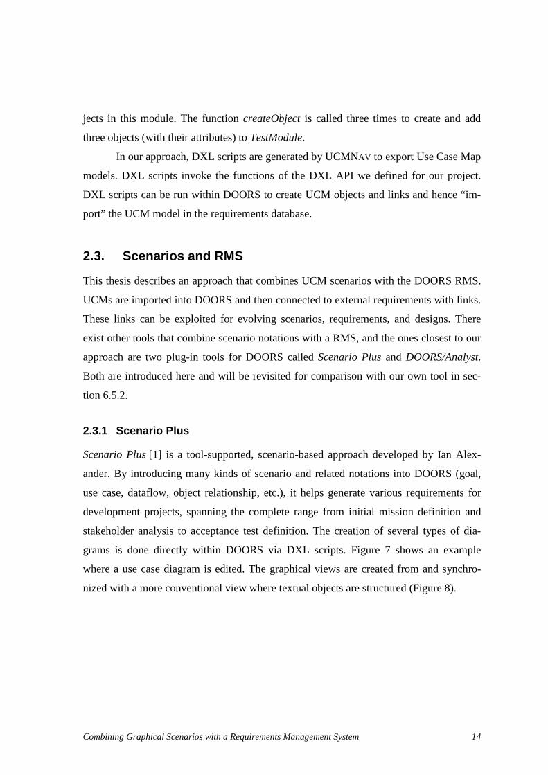
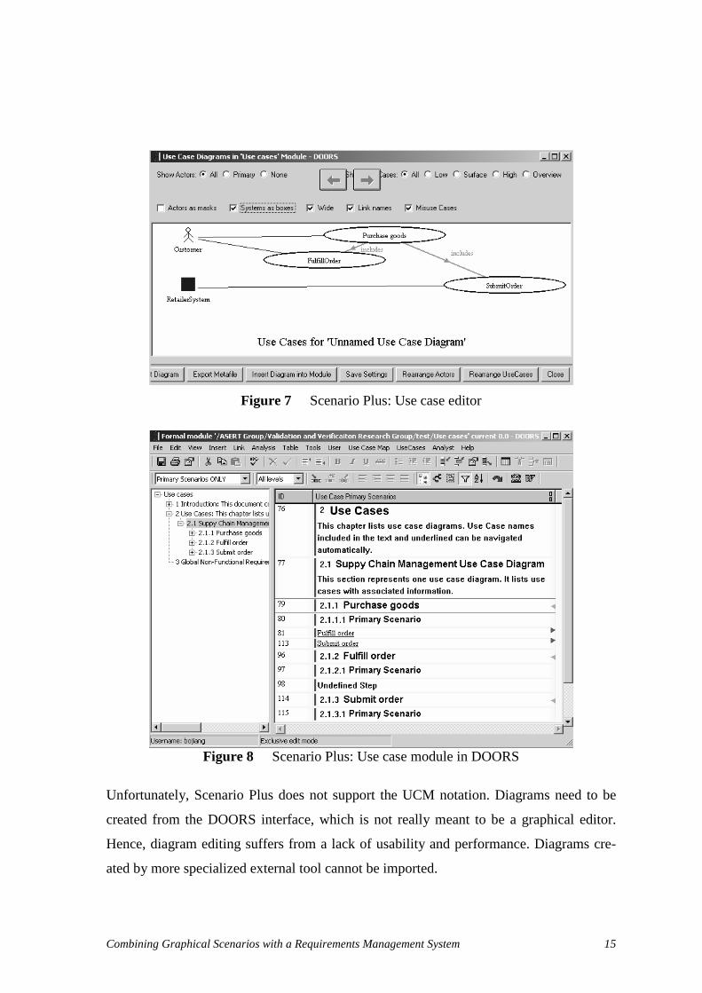
2.3.1 Scenario Plus
Scenario Plus [1] is a tool-supported, scenario-based approach developed by Ian Alex-
ander. By introducing many kinds of scenario and related notations into DOORS (goal,
use case, dataflow, object relationship, etc.), it helps generate various requirements for
development projects, spanning the complete range from initial mission definition and
stakeholder analysis to acceptance test definition. The creation of several types of dia-
grams is done directly within DOORS via DXL scripts. Figure 7 shows an example
where a use case diagram is edited. The graphical views are created from and synchro-
nized with a more conventional view where textual objects are structured (Figure 8).
Combining Graphical Scenarios with a Requirements Management System 15
Figure 7 Scenario Plus: Use case editor
Figure 8 Scenario Plus: Use case module in DOORS
Unfortunately, Scenario Plus does not support the UCM notation. Diagrams need to be
created from the DOORS interface, which is not really meant to be a graphical editor.
Hence, diagram editing suffers from a lack of usability and performance. Diagrams cre-
ated by more specialized external tool cannot be imported.

Combining Graphical Scenarios with a Requirements Management System 16
2.3.2 DOORS/Analyst
DOORS/Analyst [31] is a plug-in that enables DOORS to use UML diagrams inside re-
quirements modules. As UML 2.0 is supported [26], this tool provides support for sce-
nario-based diagrams such as Use Case Diagrams and Sequence Diagrams. Taking ad-
vantages of UML diagrams, requirements can be captured more precisely in DOORS.
UML diagrams can be embedded in any module. Double-clicking on a diagram
brings up a convivial editor, which is actually the editor used in Telelogic Tau/Developer
G2. Any modification to a diagram is synchronized with the DOORS database when the
user leaves the editor. For example, Figure 9 shows the class diagram editor.
Figure 9 DOORS/Analyst: Class diagram in editor
When leaving the editor, a bitmap version of the diagram is embedded in the module, to-
gether with objects corresponding to the main elements of the diagram (Figure 10). These
objects can be linked to other requirements, hence providing traceability relationships
between UML artefacts and requirements.

Combining Graphical Scenarios with a Requirements Management System 17
Figure 10 DOORS/Analyst: Class diagram in formal module
However, not all UML diagram elements become DOORS objects. As shown in Figure
11, the UML 2.0 sequence diagram itself is imported back to the module, but its various
elements (objects, messages, etc.) are not converted to objects and hence are not linkable.
DOORS/Analyst provides the capabilities to export these diagrams to design tools,
such as Tau/Architect and Tau/Developer, which is useful when moving from require-
ments to the design stage. However, once these diagrams are changed in the design tool,
the changes cannot be brought back to DOORS. DOORS/Analyst lacks a good update
mechanism for these diagrams.
Obviously, as DOORS/Analyst focuses on UML 2.0, it does not provide support
for expressing UCMs in DOORS.
Traceable objects are created in the module

Combining Graphical Scenarios with a Requirements Management System 18
Figure 11 DOORS/Analyst: Sequence diagram in formal module
2.4. Chapter Summary
This chapter first introduced the scenarios notation used in this thesis, Use Case Maps,
together with the UCMNAV tool (section 2.1). Then, section 2.2 presented a typical re-
quirements management system, Telelogic DOORS, with a special emphasis on its main
functionalities, structure, requirements view, and scripting language (DXL). Finally, this
chapter provided an overview of two existing tools that combine scenarios with a RMS:
Scenario Plus and DOORS/Analyst (section 2.3). The next chapter will explain how the
essence of UCM models can be exported by UCMNAV in a format understood by
DOORS.
No traceable object is created in the module (except the diagram)

Combining Graphical Scenarios with a Requirements Management System 19
Chapter 3. Exporting UCM Model from UCMNAV
This chapter describes a metamodel that represents the essence of the Use Case Map no-
tation. In section 3.1, a metamodel of the UCM notation is reverse-engineered from the
existing UCM file format supported by UCMNAV as well as other sources. Section 3.2
then explains how UCM models are exported to the target RMS, namely Telelogic
DOORS, in a format that the RMS can understand. Several exporting strategies and dif-
ficulties in the implementation are also discussed. Sections 3.3, 3.4, and 3.5 provide de-
tailed descriptions of the elements (core, maps, and scenarios) found in the metamodel,
their attributes and associations.
3.1. UCM Metamodel
3.1.1 Understanding UCMs
Currently, there is no standard metamodel for the UCM notation. However, there exist
several ways one can use to construct or recover such a metamodel. For instance, one can
use the source code of the UCM tool, UCMNAV [34], or use the UCM file formats (ex-
pressed as XML 1.1 Document Type Definitions – DTD [35]) in UCMNAV and in the
draft UCM standard (Z.152 [20]).
The source code of UCMNAV provides extensive information on UCMs. However,
in that source code, the core UCM information is mixed with many other implementation
details found in various C++ classes. Reverse-engineering a class diagram from the
source code often leads to too many classes and attributes (e.g., related to layout or de-
sign patterns), and to too few relevant associations and other relationships between these
classes. For example, Rational Rose [18] was used to reverse-engineer such a diagram. It
was useful to understand the implementation of UCMNAV, but it was indeed too complex
to extract a useful metamodel for UCMs because UCMNAV does not clearly separate the
model from the visual or layout aspects.

Combining Graphical Scenarios with a Requirements Management System 20
The UCM draft standard [20] includes a specification of the UCM notation with a
DTD, where the UCM concepts are defined in terms of elements and their attributes. The
semantics of the language is described in natural language. This DTD proposes an
XML-based interchange format for UCM tools. Implementation details are absent from
this specification. This UCM DTD provides a more concise and understandable descrip-
tion of the nature of UCMs than the source code of UCMNAV, even if it also has limita-
tions related to the identification of associations between classes in the target metamodel.
It is also more concise that the UCMNAV DTD, which includes several obsolete
UCMNAV features (such as UCM sets) irrelevant to the target metamodel.
There is also another source of useful and complementary information worth con-
sidering. UCMNAV can export scenarios resulting from the traversal of a complex UCM
model according to scenario definitions. There exists another DTD describing the export
format, also in XML (not part of the Z.152 draft standard) [7]. Since these scenarios are
also relevant to the description of UCM models and since they can be exploited by RMS
tools (e.g., by linking them to test cases), we will combine this information to the one
from the UCM DTD.
3.1.2 Creating the UCM Metamodel
Using the Z.152 and the UCM scenario DTDs as a start point, reverse-engineering tools
can be used to help the automatic generation of the class diagram describing the current
UCM metamodel. Rational Rose, which supports the reverse-engineering of models from
a DTD, was used in this thesis. This led to a flat class diagram, which was refactored
manually into several packages where the classes were sorted according to their purpose
(Figure 12). This reduced the complexity of the reverse-engineered class diagram. Sev-
eral class attributes were also transformed to more meaningful associations in the meta-
model, associations that were not reverse-engineered properly by Rational Rose.
Combining Graphical Scenarios with a Requirements Management System 21
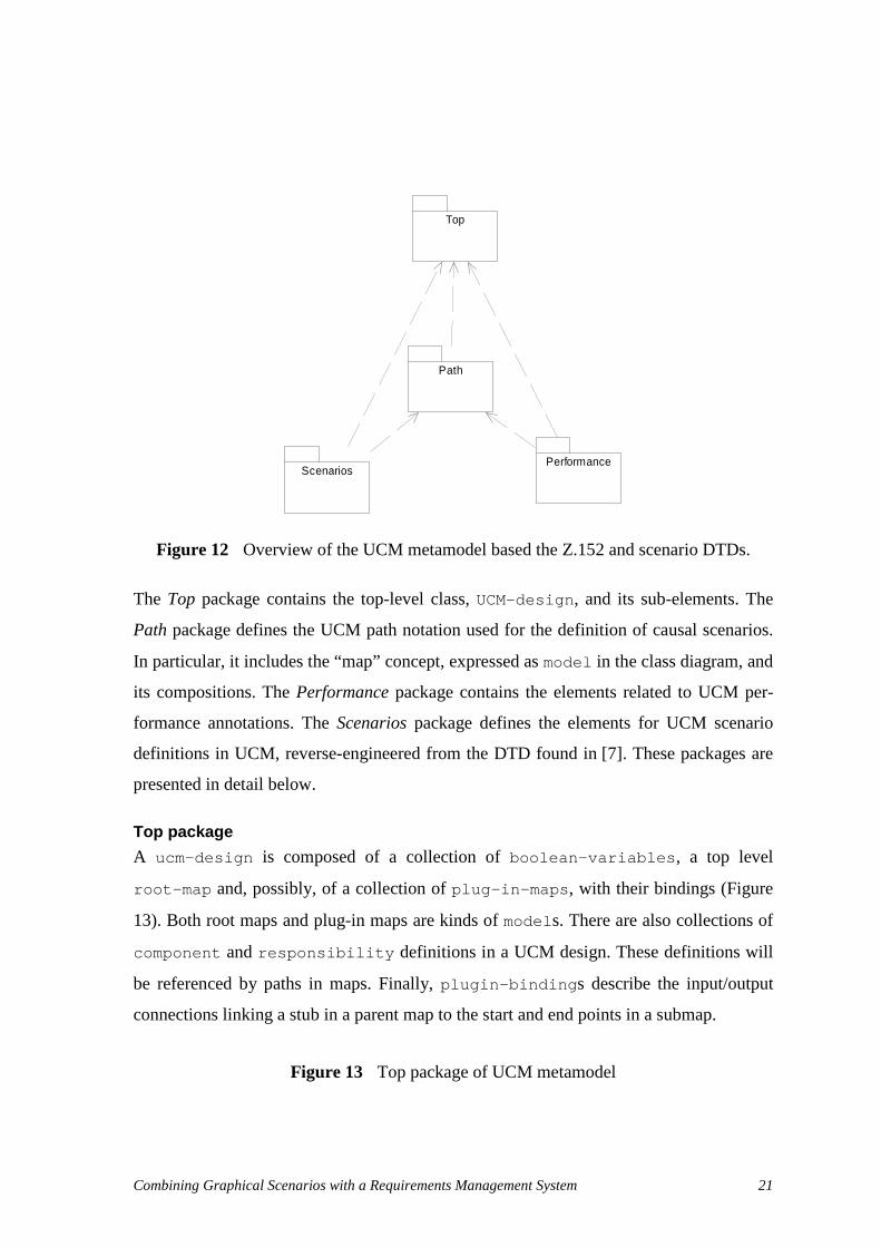
Figure 12 Overview of the UCM metamodel based the Z.152 and scenario DTDs.
The Top package contains the top-level class, UCM- desi gn, and its sub-elements. The
Path package defines the UCM path notation used for the definition of causal scenarios.
In particular, it includes the “map” concept, expressed as model in the class diagram, and
its compositions. The Performance package contains the elements related to UCM per-
formance annotations. The Scenarios package defines the elements for UCM scenario
definitions in UCM, reverse-engineered from the DTD found in [7]. These packages are
presented in detail below.
Top package
A ucm- desi gn is composed of a collection of bool ean- var i abl es , a top level
r oot - map and, possibly, of a collection of pl ug- i n- maps , with their bindings (Figure
13). Both root maps and plug-in maps are kinds of model s. There are also collections of
component and r esponsi bi l i t y definitions in a UCM design. These definitions will
be referenced by paths in maps. Finally, pl ugi n- bi ndi ngs describe the input/output
connections linking a stub in a parent map to the start and end points in a submap.
Figure 13 Top package of UCM metamodel
PerformanceScenarios
Path
Top

Combining Graphical Scenarios with a Requirements Management System 22
Path package
In this package, the path specification of a UCM model is described as a hyper gr aph
that represents the causal scenarios. A hyper gr aph is a graph structure specifying all the
elements, called hyper edges, which make up the paths (Figure 14). The different types
of hyperedges include st ar t and end- poi nt s, wai t i ng- pl aces, r esponsi bi l i t y
r ef er ences, OR-forks and OR-joins (classes f or k and j oi n), AND-joins and
AND-forks (called synchr oni zat i ons), l oops, abor t s, st ubs, performance t i me-
st amp- poi nt s, and connections (connect ) for various asynchronous and synchronous
interactions between paths.
Figure 14 Path package of UCM metamodel (1)
abort
connect join
loop
+ orientation : string+ exi t-condi tion : string
responsibi l i ty-ref
+ d irection : string+ arrow-posi tion : string
synchroization
+ cardinal i ty-source : string+ cardinal i ty-target : string
tim estamp-point
+ orientation : string+ reference : (previous | next)
(from Performance)
start
+ arrival : (exponential | deterministic | uniform | erlang | expert | none) = none+ stream-type : (open | closed) = open+ log ical-condi tion : string+ population-size : string+ mean : string+ value : string+ low : string+ h igh : string+ kernel : string+ expert-distribution : string+ label-al ignm ent : (centered | flush)
wai ting-place
+ timer : (yes | no) = no+ wai t-type : string+ log ical-condi tion : string+ timeout : string
end-point
+ label-al ignment : (centered | flush)
stub
+ type : (static | dynam ic) = static+ shared : boolean = false+ selection-pol icy : string
fork
+ orientation : string
hyperedge
+ hyperedge-id : ID+ hyperedge-nam e : string+ description : string
model
+ model-id : ID+ model-name : string+ ti tle : string = No ti tle+ description : string
(from Top)
hypergraph
0..*0..*
0..10..1

Combining Graphical Scenarios with a Requirements Management System 23
Figure 15 Path package of UCM metamodel (2)
As seen in Figure 15, a hypergraph also includes links between hyperedges, which are
called hyper edge- connect i ons. Different pr econdi t i ons and post condi t i ons
can be associated with various path elements. Additionally, stubs may contain constraints
on the plug-in maps (i.e., the sub-maps) that can be bound (enf or ced- bi ndi ngs).
Scenario package
The scenar i o- def i ni t i on element in the Top package defines a scenario by specify-
ing the start points and initial values for the Boolean variables used in the model. The
UCMNAV tool uses these definitions to highlight and export particular scenario traces.
However, to transform UCM scenarios to other scenario languages, a standalone scenario
representation is used as an intermediate representation. The class diagram in Figure 16
hyperedge-connection
hyperedge-ref
0..* +source0..*
hypergraph
0..*0..*
component-ref
+ component-ref-id : ID+ role : string+ anchored : boolean = false+ fixed : boolean = false
(from Performance)
0..n
0..1+component-parent
0..n
0..1
0..*0..*
end-point
+ label -al ignment : (centered | flush)
path-binding
+ id : ID
hyperedge
+ hyperedge-id : ID+ hyperedge-name : string+ description : string
0..*0..*
model
+ model-id : ID+ model-name : string+ ti tle : string = No title+ description : string
(from Top)
0..10..1
0..*0..*
postcondi tion
+ composition : string = AND
0..*0..*
enforce-bindings
+ enforce-binding : id0..*0..*
stub-entry
+ stub-entry-id : ID
+stub-entry
0..*
+entry
0..*
stub-exit
+ stub-exi t-id : ID
+stub-exit
0..*
+exit
0..*
plugin-binding
+ plugin-binding : id+ branch-condi tion : string+ probabi l i ty : number
(from Top) 0..1
+parent
0..10..1+submap
0..1
start
+ arrival : (exponential | deterministic | uni form | erlang | expert | none) = none+ stream-type : (open | closed) = open+ logical -condi tion : string+ population-size : string+ mean : string+ value : string+ low : string+ high : string+ kernel : string+ expert-distribution : string+ label -al ignment : (centered | flush)
wai ting-place
+ timer : (yes | no) = no+ wait-type : string+ logical -condi tion : string+ timeout : string
stub
+ type : (static | dynamic) = static+ shared : boolean = fa lse+ selection-pol icy : string
0..*0..*
0..1
+thestub
0..1
precondi tion
+ composition : string = AND
0..*0..*
0..*0..*
0..*0..*
condition
+ name : string+ description : string
responsibi l i ty-ref
+ direction : string+ arrow-posi tion : string

Combining Graphical Scenarios with a Requirements Management System 24
describes the syntax of that representation. A scenario is a partial order that can use of
sequence (seq) and parallel (par ) operators recursively. The do element, which can be
of various types, describes each UCM element visited together with the component to
which it is allocated. The condi t i on element captures the conditions satisfied during
the traversal of the UCMs (e.g., at choice points and in dynamic stubs). Scenarios can
also be grouped.
Figure 16 Scenario package of UCM metamodel
Performance package
In Use Case Maps, performance annotations (Figure 17) are composed of r e-
sponse- t i me- r equi r ement s which contain references to two timestamp-points
(starting and ending timestamp points). Devices are a necessary part of the execution en-
vironment of the performance models expressed in UCM. A devi ce could be a proces-
sor, a disk, a DSP (digital signal processing unit), or other. A device may also have a
predefined speed factor.
hyperedge
+ hyperedge-id : ID+ hyperedge-name : string+ description : string
(from Path)
condition
+ hyperedge-id : String+ label : String+ expression : String
do
+ name : String+ type : (Resp | Start | End_Point | WP_Enter | WP_Leave | Connect_Start | Connect_End | Trigger_End | Timer_Set | Timer_Reset | Timeout)+ description : String+ component-name : String+ component-role : String+ component-id : String
par
0..*0..*
seq
0..*0..*
0..*0..*
0..*0..*
scenario
+ scenario-definition-id : String+ name : String+ description : String
0..*0..*
0..10..1
group
+ group-id : String+ name : String+ description : String
0..*0..*
scenarios
+ date : String+ ucm-file : String+ design-name : String+ ucm-design-version : String
0..*0..*
ucm-design
+ design-id : ID+ design-name : string+ description : string
(from T op)
0..10..1

Combining Graphical Scenarios with a Requirements Management System 25
Figure 17 Performance package of UCM metamodel
The class diagrams discussed in this section do not exhaustively cover all the elements in
UCM. However, they are useful to UCM understanding, modifications, and future exten-
sions.
3.1.3 Principles for Exporting UCM Models
Most requirements management systems focus on structured textual requirements, with
support for traceability, access control, and version control. Structured textual require-
ments suffer from many limitations when expressing scenario information such as syn-
chronizations and interactions.
The Use Case Map notation, a scenario-oriented notation, describes multiple sce-
narios in a single, integrated view. This promotes the understanding and reasoning about
the system as a whole, as well as the early detection of conflicting or inconsistent scenar-
ios. [7]
In this thesis, a subset of the UCM model is selected and transmitted to the RMS.
This subset focuses mainly on scenario elements that are potentially useful to establish
and exploit links to/from other types of requirements. There is no technical reason pre-
hyperedge
+ hyperedge-id : ID+ hyperedge-name : string+ description : string
(from Path)
timestamp-point
+ orientation : string+ reference : (previous | next)
hyperedge-ref(from Path)
response-time-requirement
+ resptime-name : string+ response-time : string+ percentage : string+ description : string
0..n0..n
+timestamp1
0..n0..n
+timestamp2model
+ model-id : ID+ model-name : string+ title : string = No title+ description : string
(from T op)
component-ref
+ component-ref-id : ID+ role : string+ anchored : boolean = false+ fixed : boolean = false
0..n
0..1+component-parent
0..n
0..1
0..*0..*
0..*0..*
ucm-design
+ design-id : ID+ design-name : string+ description : string
(from T op)
0..*0..*
0..*+plugin
0..* 1..*+root1..*
component
+ component-id : ID+ component-name : string+ description : string+ type : (team | process | object | agent | ISR | other)+ formal : boolean = false
(from T op)
1..n1..n
+referenced-component
0..*0..*
responsibility
+ resp-id : ID+ resp-name : string+ exec-sequence : string+ description : string
(from T op)0..*0..*
device
+ device-id : ID+ device-type : (processor | disk | dsp | other)+ device-name : string+ description : string+ op-time : string
0..*0..*
0..*0..*
service-request
+ request-number : string
1
0..*
1
0..*
0..*0..*

Combining Graphical Scenarios with a Requirements Management System 26
venting one from exporting all the elements found in a UCM model, however this would
take more space in the RMS database and reduce the overall performance of the approach
for no obvious benefit.
To select the subset of UCM to be exported to the RMS, the following principles are
considered, in accordance with the objectives of the thesis.
1. Essential concepts of UCMs should be covered: As we want to establish and ex-
ploit links between scenarios and other types of requirements, basic behaviour
elements (responsibilities), basic structure elements (components), as well as their
references in maps and their containment relationships must be preserved.
2. Traceability across maps should be preserved: As we want to explore transitive
relationships between external elements and various UCM elements that could be
in different maps (e.g., for impact assessment), essential information related to
stub/plug-in relationships need to be exported.
3. Essential performance concepts should be included: As we want to enable analy-
sis between external requirements and scenarios from a performance perspective,
connections between elements and their respective devices must be exported.
4. Important scenarios should be preserved: As we want to explore transitive rela-
tionships between requirements and link UCM models to test cases, scenarios re-
sulting from the traversal of UCM models according to scenario definitions
should be included. This does not imply that we need to replicate the original hy-
pergraph structure with forks and joins (as this would cover all the scenarios,
many of which being uninteresting).
5. A minimal number of UCM elements should be exported: This is to prevent per-
formance degradation in the RMS database.
Taking these principles into consideration, the class diagram in Figure 18 shows the se-
lected subset of the UCM metamodel which will be exported to the RMS tool. Compo-
nent, responsibility and their references are selected because they are the basic elements
in UCM and have tight relationships with requirements. Components describe the entities
or objects composing the system and responsibilities represent actions, tasks, or functions
to be performed in the system. All concepts in scenarios are selected because the UCM
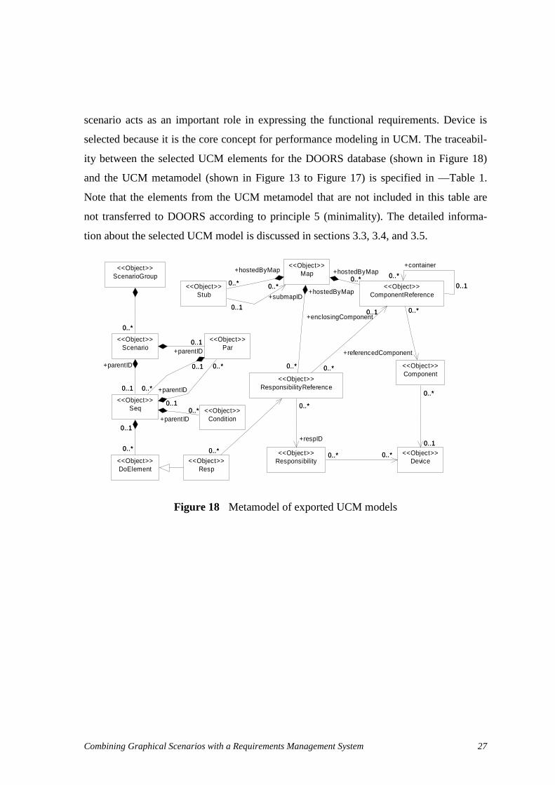
Combining Graphical Scenarios with a Requirements Management System 27
scenario acts as an important role in expressing the functional requirements. Device is
selected because it is the core concept for performance modeling in UCM. The traceabil-
ity between the selected UCM elements for the DOORS database (shown in Figure 18)
and the UCM metamodel (shown in Figure 13 to Figure 17) is specified in —Table 1.
Note that the elements from the UCM metamodel that are not included in this table are
not transferred to DOORS according to principle 5 (minimality). The detailed informa-
tion about the selected UCM model is discussed in sections 3.3, 3.4, and 3.5.
Figure 18 Metamodel of exported UCM models
Condition<<Object>>
DoElement<<Object>>
Par<<Object>>
Seq<<Object>>
0..1
0..*
+parentID
0..1
0..*
0..1
0..*
+parentID
0..1
0..*
0..*+parentID
0..*
0..1
0..*
0..1
0..*
ScenarioGroup<<Object>>
Scenario<<Object>> 0..10..1
0..1
+parentID
0..1
0..*0..*
Component<<Object>>
Device<<Object>>
0..1
0..*0..*
Stub<<Object>>
ComponentReference<<Object>>
0..*
+referencedComponent
0..*
0..*
0..1
+container
0..*
0..1
Responsibility<<Object>> 0..*0..* 0..*0..*
Map<<Object>>
0..*
+hostedByMap
0..* 0..*
0..1
+submapID
0..*
0..1
0..*+hostedByMap
0..*
Resp<<Object>>
ResponsibilityReference<<Object>>
0..1
0..*
+enclosingComponent0..1
0..*
0..*
+respID
0..*
0..*
+hostedByMap
0..*
0..*0..*0..1

Combining Graphical Scenarios with a Requirements Management System 28
Package UCM Metamodel Class
Exported Metamodel Class (Figure 18)
Justification (principles)
Path (Figure 14) model Map 1,2
Path (Figure 15) stub Stub 2
Path (Figure 14) responsibility-ref ResponsibilityReference 1
Performance (Figure 17) component-ref ComponenReference 1
Top (Figure 13) component Component 1
Top (Figure 13) responsibility Responsibility 1
Top (Figure 13) device Device 3
Scenario (Figure 16) group ScenarioGroup 4
Scenario (Figure 16) scenario Scenario 4
Scenario (Figure 16) seq Seq 4
Scenario (Figure 16) par Par 4
Scenario (Figure 16) do DoElement 4
Scenario (Figure 16) condition Condition 4
Table 1 Traceability between the UCM metamodel and the exported subset
3.2. Exporting Strategies
The potential exporting process should enable the creation of a new UCM model in the
RMS when it is imported for the first time. Evolving UCM models would be updated in
the RMS simply by reimporting them. Links should be created and updated automatically
to capture the relations between UCM objects. Attributes of the requirement module
should be used to store properties information of UCM objects.
Telelogic DOORS can accept many file formats as input in order to create re-
quirements modules, including Word, Rich Text Format, plain text, Interleaf, and
FrameMaker. However, such importing mechanisms have some limitations. Firstly,
DOORS can only create a new requirements model for the imported information and
cannot recognize and updated version of the source document (to the requirements mod-
ule cannot be updated accordingly). Secondly, DOORS cannot create links between the
imported objects. Last, DOORS cannot create attributes for the imported objects. These
formats hence are not good candidates for the importing and updating of UCM scenario
information in the DOORS repository.

Combining Graphical Scenarios with a Requirements Management System 29
We could import the XML files generated by UCMNAV into DOORS. However,
some information about the UCM model is not expressed in the XML file directly and
requires further analysis. For instance, figures of maps are not provided in the XML file
generated from UCMNAV. They can only be obtained by redrawing all items specified in
the XML file. Scenarios with concrete steps are also missing; only scenario definitions
are specified. Concrete scenarios steps can only be constructed by applying a complex
scenario traversal mechanism.
Another possibility is having UCMNAV export UCMs in another, more suitable,
XML format capturing the elements, attributes, and associations identified in Figure 18.
This could lead to a file format independent of DOORS and reusable but other tools (such
as Requisite Pro). However, XML files cannot be read by DOORS directly, and a
DOORS XML parser or a converter from XML to a format understandable by DOORS
would need to be created.
A better strategy would be to express UCM models as DXL (DOORS eXtension
Language) scripts, which have can be read and run by DOORS directly. DXL is a script-
ing language specially developed for DOORS. It provides some key features, such as file
format importers and exporters, impact and traceability analysis and inter-module linking
tools. Hence, from a DOORS perspective, DXL scripts become a simple format for han-
dling UCM models. However, there are several ways of generating DXL scripts, some of
which are explored in the following sub-sections.
3.2.1 Generating DXL Scripts Directly From UCMNAV
In this strategy, a DXL library is predefined and used to run DXL scripts exported from
UCMNAV and imported in DOORS (Figure 19). In the DXL library, each class in the se-
lected subset of UCM model has a corresponding DXL function whose parameters store
the information of the class attributes and its associations to other classes. UCMNAV can
be enhanced to have the ability to export DXL script files compliant to the selected subset
of UCM model which is proposed in section 3.1.3.

Combining Graphical Scenarios with a Requirements Management System 30
Figure 19 Generating and importing DXL scripts
For each object in the selected subset of UCM model, the new UCMNAV will export one
DXL script composed of a sequence of DXL function invocations containing a function
name (corresponding to a class name in Figure 18) together with parameters specifying
attribute data and associations with other objects. Figure 20 shows an example of a func-
tion called from the DXL library as generated by UCMNAV. Details about the function
call are explained in section 4.2.2.
Figure 20 DXL script example
3.2.2 Alternative Strategies
One alternative strategy is to use XML as the interchange format for the UCM model (see
Figure 21). UCMNAV could generate a XML corresponding to the UCM model. An in-
dependent XML to DXL converter could be implemented and used to handle the XML
file generated by UCMNAV. The converter could take advantages of XSLT processors to
parse and convert the XML file, given an XSLT definition of the transformation. A vari-
ant strategy would be to have a converter which is not based on XSLT (and that could be
integrated to UCMNAV).
r espRef ( " h12" , 230 , 344 , " m0" , " cr 1" , " r 7" , " f wd_si g" , " For war ds any si gnal r ecei ved" , " UP" )

Combining Graphical Scenarios with a Requirements Management System 31
Figure 21 Generating DXL scripts via XML
There is another variation to the above strategies where DOORS would parse XML files
and generate the UCM model internally. In this strategy, the DXL library needs to be
supplemented with an XML parser, which is used to extract the model information out of
the XML file. However, implementing such a XML parser in DXL would require much
effort and, since DXL is an interpreted language, this would slow the import process.
All these strategies require invocations to the DXL library to be present in a script.
Having an XML representation of the UCM model in between would promote some in-
dependence from a specific RMS tool, but it would also require the presence of another
tool (e.g., Xerces) to convert the XML files to DXL. In this thesis, since we are targeting
only one RMS candidate (Telelogic DOORS), there is not much value in using XML as
an intermediate format. Therefore, the first strategy is adopted in this thesis to keep the
import process simple and easily implementable. Figure 3 shows the new “File -> Export
DXL” menu item we have added to UCMNav to trigger this export. This could be modi-
fied at a later time to support other RMS tools, if required.
The following three sections will refine and detail the elements, attributes, and asso-
ciations of the metamodel found in Figure 18. Section 3.3 presents the core elements,
section 3.4 focuses on the individual maps, whereas section 3.5 presents the scenarios.

Combining Graphical Scenarios with a Requirements Management System 32
3.3. Core Elements and Their Associations
Core elements discussed in this section are not included in any map or scenario directly.
However, these definitions are fundamental elements of a UCM model. Responsibilities
show system behaviors referenced by scenarios and by maps. Components describe the
structural entities of a UCM model. Devices are used to express performance-related de-
ployment in the UCM model.
3.3.1 Metamodel
The metamodel in Figure 22 details some of the classes from Figure 18. Some of the at-
tributes found in the corresponding classes in Figure 13 have been removed while others
are added to meet the needs of creating UCM maps in DOORS. Note that the «Object»
stereotype used in the following diagrams indicates that instances of these classes will
correspond to DOORS objects.
Figure 22 Core elements metamodel of exported UCM
3.3.2 Class Specification
Responsibility
Description
Responsibilities are processing tasks (e.g., procedures, functions, actions, etc.) that are
referenced by scenarios and by maps.
Component
- name : String- ID : String- type : String- theDescription : String
<<Object>>Responsibility
- ID : String- name : String- processorDemand : String- theDescription : String
<<Object>>
Device
- ID : String- name : String- theDescription : String- speedFactor : String
<<Object>>
0..*
0..1
0..* 0..*
0..*
0..*
0..*0..1

Combining Graphical Scenarios with a Requirements Management System 33
Attributes
ID: String The identifier of the responsibility. name: String The name of the responsibility. processorDemand: String Quantifies the demand on the processor associ-
ated with the responsibility. Used for performance analysis.
theDescription: String Description of the responsibility. Associations
device: device [0..*] A responsibility may request many devices.
Component
Description
Components represent, at the requirements level, abstract entities corresponding to actors,
processes, objects, containers, agents, and so on.
Attributes
ID: String The identifier of the component. name: String The name of the component. type: String The type of component (Team, Object, Process,
Agent, …). theDescription: String Description of the component.
Associations
device: device [0.1] A component is hosted by zero or one device.
Device
Description
A device can be a processor, a disk, a DSP or anything else (other). A device may also
have a predefined speed factor (corresponding to op-time in a UCM device).
Attributes
ID: String The identifier of the device. name: String The name of the device. theDescription: String Description of the device. speedFactor: String Speed factor (operation time) of the device.

Combining Graphical Scenarios with a Requirements Management System 34
3.3.3 Sample of DXL Scripts on UCM Core Model
Figure 23 DXL script for the core elements in the Simple Telephone System
Details information about the functions used in Figure 23 are explained in section 4.2.1.
Begi nOf Cor eI mpor t / / Devi ces devi ce( " d0" , " DBase" , " " , " 0" ) devi ce( " d1" , " Di sk" , " " , " 0" ) / / Map " CND" r esponsi bi l i t y( " r 6" , " di spl ay" , " Di spl ays t he or i gi nat or ' s number . " , " 0" ) / / Map " OCS"
r esponsi bi l i t y( " r 2" , " checkOCS" , " Checks whet her t he t er mi nat or i s i n t he or i gi nat or ' s OCS l i st . chkOCS t akes t he val ue F" , " 0" )
r esponsi bi l i t y( " r 5" , " deny" , " Deni es t he connect i on. " , " 0" ) / / Map " Or i gi nat i ng"
r esponsi bi l i t y( " r 10" , " snd- r eq" , " Send t he connect i on r equest t o t he t er mi nat i ng agent . " , " 0" )
r esponsi bi l i t y( " r 0" , " I ni t Feat ur es" , " I ni t i al i ses t he l i st of f eat ur es t o be checked accor di ng t o t hei r subscr i pt i on i nf or mat i on. For each f eat ur e F: chkF t akes t he val ue of subF" , " 0" )
/ / Map " TeenLi ne" component ( " c1" , " User " , " Team" , " " , " " ) r esponsi bi l i t y( " r 4" , " checkTi me" , " Checks t hat TeenLi ne i s act i ve, i . e. t hat t he
connect i on i s i n t he pr e- def i ned t i me r ange. chkTL t akes t he val ue F. " , " 0" )
r esponsi bi l i t y( " r 5" , " deny" , " Deni es t he connect i on. " , " 0" ) r esponsi bi l i t y( " r 3" , " checkPI N" , " Checks t hat t he PI N i s val i d. " , " 0" ) / / Map " Ter mi nat i ng" r esponsi bi l i t y( " r 1" , " busyTr eat ment " , " Thi s user i s busy and cannot answer . Pr epar e
busy si gnal . " , " 0" ) r esponsi bi l i t y( " r 9" , " r i ngi ngTr eat ment " , " Thi s user i s avai l abl e. Pr epar e r i ngback
s i gnal . " , " 0" ) r esponsi bi l i t y( " r 8" , " r i ngTr eat ment " , " Pr epar e r i ng si gnal . " , " 0" ) / / Map " r oot " component ( " c1" , " User " , " Team" , " " , " " ) component ( " c0" , " Agent " , " Agent " , " " , " " ) component ( " c0" , " Agent " , " Agent " , " " , " " ) component ( " c1" , " User " , " Team" , " " , " " ) r esponsi bi l i t y( " r 7" , " f wd_si g" , " For war ds any si gnal r ecei ved f r om t er mi nat i ng
agent s" , " 0" ) r esponsi bi l i t y( " r 7" , " f wd_si g" , " For war ds any si gnal r ecei ved f r om t er mi nat i ng
agent s" , " 0" ) endOf Cor eI mpor t

Combining Graphical Scenarios with a Requirements Management System 35
3.4. Maps and Their Associations
Maps define functional requirements models as causal scenarios (paths). Maps contain
specifications for systems structure (component references), behavior (responsibility ref-
erences), as well as stubs. Only core maps concepts are exported to DOORS as well as
their relationships. The composition relationships between map with component refer-
ences and responsibility references will be represented as parent-child object relation-
ships in DOORS. More information about expressing scenario in DOORS is discussed in
section 4.2.2.
3.4.1 Metamodel
Some classes are omitted from the metamodel from Figure 15 in order to simplify the
map model to be exported to DOORS. Some associations between classes are adjusted to
describe the map model more precisely. More attributes are added to classes in the map
metamodel to meet the needs of creating UCM maps in DOORS (Figure 24).
Figure 24 Map metamodel of exported UCM
Responsibility
ID : Stringname : StringprocessorDemand : StringtheDescription : String
<<Object>>ResponsibilityReference
ID : Stringfx : Integerfy : IntegerenclosingComponent : Stringname : StringtheDescription : Stringdirection : String
<<Object>>
+respID
0..*0..*
Map
ID : Stringname : StringgraphFileName : Stringtitle : StringtheDescription : String
<<Object>>
0..*0..*
+hostedByMap
Stub
ID : Stringfx : Integerfy : Integername : StringstubType : String
<<Object>>
0..*0..*
+hostedByMap
+submapID
0..10..* 0..10..*
Component
name : StringID : Stringtype : StringtheDescription : String
<<Object>>
ComponentReference
componentRefID : Stringfx : Integerfy : Integerwidth : Integerheight : Integeranchored : Stringname : Stringrole : String
<<Object>>
0..*0..*
+referencedComponent
0..*0..* +hostedByMap
0..*
0..1
0..*
+enclosingComponent
0..1
1..*
0..10..1
1..*+container

Combining Graphical Scenarios with a Requirements Management System 36
3.4.2 Class Specifications
Map
Description
A Map is basically a collection of causal scenarios (paths). It contains specifications for
systems structure (component references), behaviour (responsibility references), as well
as stubs.
Attributes
ID: String The identifier of the map. name: String The name of the map. graphFileName: String The name of the graph file exported for the map. title: String The title of map. theDescription: String Description of the map.
Associations
stub : Stub [0..*] A map contains zero or more stubs. compRef : ComponentRefer-ence [0..*]
A map contains zero or more ComponentRefer-ence objects.
respRef : Responsibili-tyReference [0..*]
A map contains zero or more Responsibili-tyReference objects.
Stub
Description
In a UCM, stubs are used as containers for plug-in maps (i.e. sub-maps). Stubs can be
static or dynamic. While static stubs contain only one plug-in, dynamic stubs may contain
multiple plug-ins. X-Y coordinates are generated for future use (to enable clickable UCM
diagrams in DOORS).
Attributes
ID: String The identifier of the stub. name: String The name of the stub. fy: Integer The vertical (Y) coordinate of the stub on the
map. fx: Integer The horizontal (X) coordinate of the stub on the
map. stubType: String The type of stub (static or dynamic).
Associations
HostedByMap: map[0..*] A stub is contained by one map. submapID: map[0..*] A stub contains zero or more plug-in maps.

Combining Graphical Scenarios with a Requirements Management System 37
ComponentReference
Description
A component reference refers to a component defined in the core model (section 3.3.2).
A component reference has its own role and responsibility list which references valid re-
sponsibility references. Again coordinates and sizes are captured for future usage.
Attributes
ID: String The identifier of the component reference. name: String The name of the component reference. fy: Integer The vertical (Y) coordinates of the component
reference on the map. fx: Integer The horizontal(X) coordinates of the component
reference on the map. width: Integer The width of the component reference on the
map. height: Integer The height of the component reference on the
map. anchored : String Indicates whether the object is anchored or not. role: String The role of the component reference.
Associations
hostedByMap: Map[0..*] A component reference is contained by zero or more maps.
referencedComponent : Com-ponent
One or many component references can refer to the same Component.
container : ComponentRefer-ence[0..*]
A component reference contains zero or more component references.
ResponsibilityReference
Description
A responsibility reference refers to a responsibility defined in the core model (section
3.3.2).
Attributes
ID: String The identifier of the responsibility reference. name: String The name of the responsibility reference. fy: Integer The vertical (Y) coordinates of the responsibility
reference on the map. fx: Integer The horizontal (X) coordinates of the responsibil-
ity reference on the map. theDescription: String Description of the responsibility reference. direction: String The direction of responsibility ref. on the path.
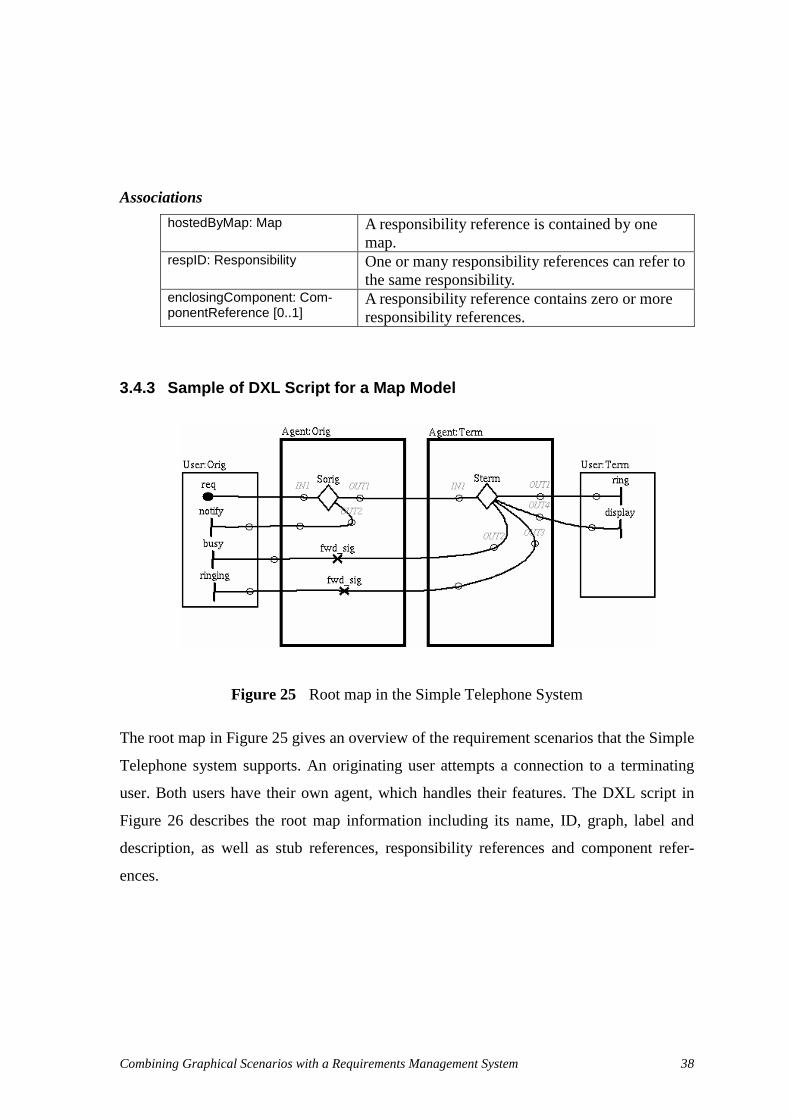
Combining Graphical Scenarios with a Requirements Management System 38
Associations
hostedByMap: Map A responsibility reference is contained by one map.
respID: Responsibility One or many responsibility references can refer to the same responsibility.
enclosingComponent: Com-ponentReference [0..1]
A responsibility reference contains zero or more responsibility references.
3.4.3 Sample of DXL Script for a Map Model
Figure 25 Root map in the Simple Telephone System
The root map in Figure 25 gives an overview of the requirement scenarios that the Simple
Telephone system supports. An originating user attempts a connection to a terminating
user. Both users have their own agent, which handles their features. The DXL script in
Figure 26 describes the root map information including its name, ID, graph, label and
description, as well as stub references, responsibility references and component refer-
ences.

Combining Graphical Scenarios with a Requirements Management System 39
Figure 26 DXL script generated for the Root map in the Simple Telephone System
3.5. Scenarios and Their Associations
Scenario traces generated from UCMs can capture the causal relationships between re-
sponsibilities for particular scenario instances. This is useful for understanding specific
situations, as well as for providing guidance for the development of validation test cases.
All the scenarios concepts are exported to DOORS including their relationships. However
links are not used to express the inter-relationships between scenario elements in DOORS
because of the large quantity of inter-relationships in scenario. Instead, composition and
sequential relationships between DOORS objects are used for describing the in-
ter-relationships in scenario. More information about expressing scenario in DOORS is
discussed in section 4.2.3.
3.5.1 Metamodel
The metamodel is based on the UCM scenario DTD, version 1. Some associations be-
tween classes are adjusted to descript the scenario model more precisely. More attributes
are added to classes in the scenario metamodel to meet the needs of creating UCM sce-
narios in DOORS.
map( " m0" , " r oot " , " s i mpl et el ephone- sol - r oot . bmp" , " Si mpl e Connect i on" , " Descr i pt i on" ) r espRef ( " h12" , 230, 344, " m0" , " cr 1" , " r 7" , " f wd_si g" , " For war ds any si gnal r ecei ved f r om
t er mi nat i ng agent s" , " UP" ) r espRef ( " h14" , 239 , 387 , " m0" , " cr 1" , " r 7" , " f wd_si g" , " For war ds any si gnal r ecei ved f r om
t er mi nat i ng agent s" , " UP" ) st ubRef ( " h23" , 427 , 262 , " m0" , " St er m" , " st at i c" , " m6; " )
st ubRef ( " h24" , 218 , 263 , " m0" , " Sor i g" , " st at i c" , " m4; " ) compRef ( " cr 0" , 551, 231 , 98 , 164, " no" , " m0" , " c1" , " User " , " Ter m" , " " ) compRef ( " cr 1" , 156, 187 , 162 , 272, " no" , " m0" , " c0" , " Agent " , " Or i g" , " " ) compRef ( " cr 2" , 350, 187 , 163 , 271, " no" , " m0" , " c0" , " Agent " , " Ter m" , " " ) compRef ( " cr 3" , 26, 231 , 99 , 176, " no" , " m0" , " c1" , " User " , " Or i g" , " " )

Combining Graphical Scenarios with a Requirements Management System 40
Figure 27 Scenario metamodel of exported UCM
3.5.2 Class Specification
ScenarioGroup
Description
Related scenarios can be put in one scenario group.
Attributes
ID: String The identifier of the scenario group. name: String The name of the scenario group. theDescription: String Description of the scenario group.
Associations
scenario : Scenario [0..*] A scenario group contains zero or more scenarios.
ScenarioGroup
- name : String- ID : String- theDescription : String
<<Object>>Scenario
- name : String- ID : String- theDescription : String
<<Object>>
0..*0..*
Condition
- ID : String- Label : String- Expression : String- presibling : String
<<Object>>
Par
- ID : String
<<Object>>
0..*+parentID
0..*
0..10..1
DoElement
- ID : String- hyperEdgeID : String- name : String- doType : String- theDescription : String- componentReferenceName : String- componentReferenceID : String- componentRole : String- preSibling : String
<<Object>>
Seq
- ID : String
<<Object>>
0..10..1
+parentID
0..1
0..*0..*
0..*0..*
+parentID
0..*
0..1
0..*
+parentID0..1
0..*
0..1
0..*
+parentID0..1
0..*0..*
+parentID
Resp<<Object>>
0..1

Combining Graphical Scenarios with a Requirements Management System 41
Scenario
Description
Scenario captures the causal relationships between responsibilities for particular scenario
instances.
Attributes
ID: String The identifier of the scenario. name: String The name of the scenario. theDescription: String Description of the scenario.
Associations
Par : Par [0..1] A Scenario contains zero or one Par root object. seq : Seq [0..1] A Scenario contains zero or one Seq root object.
Constraints
• Scenario cannot contain a root Par object and a root Seq object at the same time.
Par
Description
Par is a parallel operator expressing that the relationships between elements under the Par
are parallel.
Attributes
ID: String The identifier of the par. Associations
parentID: String Parent of the current Par object. par : Par [0..*] Par contains zero or more Par objects. seq : Seq [0..*] Par contains zero or more Seq objects.
Notes
In the scenario DTD for UCM, version 1, the Par can contain DoElement objects and
Condition objects. Actually, this cannot happen when generating a scenario with
UCMNAV. Therefore, in the scenario metamodel proposed in this thesis, Par objects
cannot contain DoElement objects and Condition objects.
Seq
Description
Seq is a sequence operator expressing that the relationships between elements under Seq
are sequential.
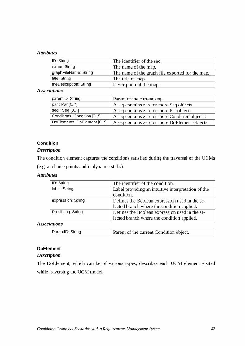
Combining Graphical Scenarios with a Requirements Management System 42
Attributes
ID: String The identifier of the seq. name: String The name of the map. graphFileName: String The name of the graph file exported for the map. title: String The title of map. theDescription: String Description of the map.
Associations
parentID: String Parent of the current seq. par : Par [0..*] A seq contains zero or more Seq objects. seq : Seq [0..*] A seq contains zero or more Par objects. Conditions: Condition [0..*] A seq contains zero or more Condition objects. DoElements: DoElement [0..*] A seq contains zero or more DoElement objects.
Condition
Description
The condition element captures the conditions satisfied during the traversal of the UCMs
(e.g. at choice points and in dynamic stubs).
Attributes
ID: String The identifier of the condition. label: String Label providing an intuitive interpretation of the
condition. expression: String Defines the Boolean expression used in the se-
lected branch where the condition applied. Presibling: String Defines the Boolean expression used in the se-
lected branch where the condition applied. Associations
ParentID: String Parent of the current Condition object.
DoElement
Description
The DoElement, which can be of various types, describes each UCM element visited
while traversing the UCM model.

Combining Graphical Scenarios with a Requirements Management System 43
Attributes
ID: String The identifier of the doElement. hyperEdgeID: String The identifier of the UCM hyperEdge referred by
the current object. doType: String The type of element visited, which is one of the
set (Resp | Start | End_Point | WP_Enter | WP_Leave | Connect_Start | Connect_End | Trig-ger_End | Timer_Set | Timer_Reset | Timeout).
theDescription: String Description of the current doElement. parentID: String Parent of the current DoElement object. presibling: String Identifier of previous sibling of the current
doElement. Notes DoElement is not equal to a UCM HyperEdge. UCM Loop, Fork, Join, Synchronization,
and Stub hyperedges have no DoElement equivalent.
Resp Description A type of DoElement, expresses one visit of the responsibility reference in the map when
traversing the scenario.
Attributes Associations
responsibilityRef:ResponsibilityReference Many Resp objects can refer to the same ResponsibilityReference object.

Combining Graphical Scenarios with a Requirements Management System 44
3.5.3 Sample of UCM Scenarios Scripts
Figure 28 Successful Basic Call Scenario in the Simple Telephone System
The highlighted paths in Figure 28 describe the successful basic call scenario in a Simple
Telephone system. Upon the request of an originating user (req), the originating agent
selects the appropriate user feature in stub Sorig (no feature selected in this case). Then
the terminating agent selects another feature in stub Sterm (also no feature). The termi-
nating agent sends ringing signals to both originating and terminating users. The corre-
sponding DXL script is shown in Figure 29.
a) Root Map
c) Sterm Plug-in Map b) Sorig Plug-in Map
d) Default Plug-in Map e) Default Plug-in Map

Combining Graphical Scenarios with a Requirements Management System 45
Figure 29 DXL script of the successful BasicCall scenario
This section discussed the scenario metamodel in DOORS. However, in some cases, sce-
narios may not be defined in the UCM model. Therefore, the scenario part can be absent
in the DXL script generated from UCMNAV. Details information about the functions
used in Figure 29 are explained in section 4.2.3.
3.6. Implementation of the Export
To automate the proposed DXL export mechanism, UCMNAV was enhanced to support
new functionalities. A few difficulties were faced along the way, especially given the ab-
sence of real architecture and documentation for the tool (hence the need to re-
verse-engineer a metamodel for UCMs as explained earlier in this chapter).
The original UCMNAV functionalities were kept unchanged. However, new meth-
ods were added to many classes to generate DXL scripts from the internal object model.
Most of the new methods are based on existing code for saving UCM models to XML
files. For instance:
• An Out put DXL( ) method was added to several classes in order to generate DXL
function calls describing the core elements and their associations (responsibilities,
components, devices), as shown in section 3.3.
scenar i oGr oup ( " Basi cCal l " , " scenar i oGr oup- Basi cCal l " , " " ) scenar i o( " BCsuccess" , " scenar i oGr oup- Basi cCal l _scenar i o- BCsuccess" , " " ) seq( " seq0" , " scenar i oGr oup- Basi cCal l _scenar i o- BCsuccess" ) doEl ement ( " h0" , " " , " r eq" , " St ar t " , " " , " User " , " cr 3" , " Or i g" , " seq0" , " NULL" ) doEl ement ( " h50" , " " , " st ar t " , " Connect _St ar t " , " " , " Agent " , " cr 1" , " Or i g" , " seq0" , " h0" ) doEl ement ( " h55" , " " , " I ni t Feat ur es" , " Resp" , " " , " Agent " , " cr 1" , " Or i g" , " seq0" , " h50" ) condi t i on( " h65" , " Def aul t " , " ! ( bv9+bv8) " , " seq0" , " h55" ) doEl ement ( " h34" , " " , " st ar t " , " Connect _St ar t " , " " , " Agent " , " cr 1" , " Or i g" , " seq0" , " h65" ) doEl ement ( " h36" , " " , " cont i nue" , " Connect _End" , " " , " Agent " , " cr 1" , " Or i g" , " seq0" , " h34" ) condi t i on( " h57" , " [ NoFeat ur eLef t ] " , " ! ( bv9+bv8) " , " seq0" , " h36" ) doEl ement ( " h49" , " " , " snd- r eq" , " Resp" , " " , " Agent " , " cr 1" , " Or i g" , " seq0" , " h57" ) doEl ement ( " h51" , " " , " success" , " Connect _End" , " " , " Agent " , " cr 1" , " Or i g" , " seq0" , " h49" ) doEl ement ( " h100" , " " , " st ar t " , " Connect _St ar t " , " " , " Agent " , " cr 2" , " Ter m" , " seq0" , " h51" ) condi t i on( " h104" , " [ not Busy] " , " ! bv6" , " seq0" , " h100" ) par ( " par 0" , " seq0" ) seq( " seq1" , " par 0" ) condi t i on( " h119" , " Def aul t " , " ! bv5" , " seq1" , " NULL" ) doEl ement ( " h34" , " " , " st ar t " , " Connect _St ar t " , " " , " Agent " , " cr 2" , " Ter m" , " seq1" , " h119" ) doEl ement ( " h36" , " " , " cont i nue" , " Connect _End" , " " , " Agent " , " cr 2" , " Ter m" , " seq1" , " h34" ) doEl ement ( " h116" , " " , " r i ngTr eat ment " , " Resp" , " " , " Agent " , " cr 2" , " Ter m" , " seq1" , " h36" ) doEl ement ( " h101" , " " , " success" , " Connect _End" , " " , " Agent " , " cr 2" , " Ter m" , " seq1" , " h116" ) doEl ement ( " h1" , " " , " r i ng" , " End_Poi nt " , " " , " User " , " cr 0" , " Ter m" , " seq1" , " h101" ) seq( " seq2" , " par 0" ) doEl ement ( " h99" , " " , " r i ngi ngTr eat ment " , " Resp" , " " , " Agent " , " cr 2" , " Ter m" , " seq2" , " NULL" ) doEl ement ( " h112" , " " , " r epor t Success" , " Connect _End" , " " , " Agent " , " cr 2" ,
" Ter m" , " seq2" , " h99" )

Combining Graphical Scenarios with a Requirements Management System 46
• A SaveDXL( ) method was added to the Hyper edge class, which invokes the
SaveDXLDet ai l s( ) method of the specific hyperedge subclass where additional
information needs to be output (e.g. for responsibility references and stubs). The
SaveDXL( ) of the Map class calls the SaveDXL( ) method on all the hyperedges
composing a particular map, and it also generates information on the map com-
ponents as well as on the file that contains the bitmap version of the map. These
new methods are used to export maps and their associations (section 3.4)
• Similar methods were added to the scenario classes, which are invoked by the
traversal mechanism during scenario generation. These methods, which are in-
spired from existing code that exports scenarios in XML [7], generate the DXL
code describing scenarios and their associations (section 3.5). The export mecha-
nism requires that the scenario definitions be valid (e.g., the traversal should not
stop prematurely due to a condition that cannot be met or to a non-deterministic
choice) for the DXL export to work properly.
The framework is hence in place to export new or different types of attributes or UCM
elements if needed. Special attention was paid not to change the values of any class prop-
erty in UCMNAV in order to prevent undesirable feature interactions.
Despite our desire not to modify the existing functionalities, several bugs in
UCMNAV caused much inconvenience during the implementation of the DXL export
mechanism. For instance, identifiers for UCM objects (e.g., responsibilities and compo-
nents) kept changing each time a UCM model was saved and loaded. This in turn dis-
turbed the update of the UCM model in DOORS, because our model import approach (to
be discussed in the next chapter) relies on the fact that object identifiers do not change
from one version to the next. UCMNAV was therefore improved, with the help of Gunter
Mussbacher, to ensure that identifiers remain unique and unchanged as the UCM model
evolves.
3.7. Chapter Summary
In this chapter, we have presented an approach to export UCMs from UCMNAV. The tool
was enhanced to export a selected subset of the UCM object model in the form of a DXL
script. As a start point, a UCM metamodel was reverse-engineered from existing XML

Combining Graphical Scenarios with a Requirements Management System 47
file formats and from other sources. A subset of that metamodel was selected for the ex-
port based on several principles (section 3.1). In section 3.2, several candidate export
strategies were explored and one based on the direct generation of DXL code was se-
lected. Sections 3.3, 3.4, and 3.5 gave detailed specifications of the formats used to de-
scribe the three major parts of the metamodel: core, maps, and scenarios. The implemen-
tation of this strategy in UCMNAV was briefly discussed in section 3.6.
The next chapter will address the issue of importing in the DOORS requirements
management system the UCM models exported as DXL scripts.

Combining Graphical Scenarios with a Requirements Management System 48
Chapter 4. Importing UCM Models in DOORS
This chapter presents an approach to represent the metamodel discussed in Chapter 3 in
the target RMS, Telelogic DOORS, based on the DXL scripts generated from the
UCMNAV tool. A DXL library is created to support the import of UCM models in
DOORS. This chapter then discusses traceability inside the UCM model and traceability
between the UCM model and other requirements.
This chapter is mainly focused on the first time import of a UCM model in
DOORS. The issues related to the updating of an existing UCM model are addressed
in Chapter 5.
4.1. Metamodel of the UCM model in DOORS
Projects, folders and formal modules compose the DOORS hierarchy. Projects are used
to manage the data related to a specific project, product or process for a team. Folders are
used to structure the data within the database. Both projects and folders can contain
sub-folders, sub-projects, and formal modules. Formal modules are containers for re-
quirements information. Typically, formal modules are structured and displayed as a
document. However, a formal module also can be structured and displayed as a data file
by using user-defined attributes. This facility is used by the UCM import process pro-
posed in this thesis to store UCM objects information, including attributes and graphics,
into DOORS.
This thesis proposes that a UCM model be introduced into a target project for
better describing functional requirements and testing goals. Figure 30 shows the proposed
UCM metamodel as represented in DOORS. This metamodel adds DOORS structuring
elements (folders and modules) on top of the metamodel previously presented in Figure
18 (and further detailed in Figure 22, Figure 24, and Figure 27). To import a UCM model
into DOORS according to the proposed UCM metamodel, a specific folder, namely UCM

Combining Graphical Scenarios with a Requirements Management System 49
model, is created under the target project. The imported UCM model is composed of
three sub-folders: Core, Maps and Scenarios.
The Core folder has three modules: Components, Responsibilities, and Devices.
These three modules list the three fundamental UCM element types we decide to preserve
in DOORS-specific term, i.e., as objects. The Maps folder contains one module, which
has the same name as the UCM design model. This module lists the maps and references
appearing in maps such as component references, responsibility references, and stubs.
The Scenarios folder also contains a module (named after the UCM model design name),
which contains grouped scenarios.
Figure 30 UCM metamodel in DOORS
DOORS links are created to represent the associations found in the UCM metamodel,
except for composition relationships. The latter are represented by the containment rela-
tionship between the DOORS database items, such as a folder containing modules or
other folders, a module containing objects, or an object containing sub-objects.
Condition<<Object>>
DoElement<<Object>>
Par<<Object>>
Seq<<Object>>
0..1
0..*
+parentID
0..1
0..*
0..1
0..*
+parentID0..1
0..*
0..*
+parentID
0..*0..*
+parentID
0..*
Scenario<<Object>> 0..10..1
0..1
+parentID
0..1
Components<<Module>>
Devices<<Module>>
Component<<Object>>
0..*0..*
Stub<<Object>>
Responsibilities<<Module>>
Device<<Object>>
0..*0..*
0..1
0..*
0..1
0..*
ComponentReference<<Object>>
0..*
+referencedComponent
0..*
0..* 0..1
+container0..* 0..1
Respons ibility<<Object>>
0..*0..*
0..*
0..*
0..*
0..*
Respons ibilityReference<<Object>>0..1 0..*
+enclosingCom ponent
0..1 0..*
0..*
+respID
0..*
Resp<<Object>>
0..*0..*
Map<<Object>>
0..*
+hostedByMap
0..*
0..*
0..1
+submapID
0..*
0..1
0..*
+hostedByMap
0..*0..*
+hos tedByMap
0..*
Des ignMaps<<Module>>
0..*0..*
Core<<Folder>> Maps
<<Folder>>
UCMmodel<<Folder>>
ScenarioGroup<<Object>>
0..*0..*
Des ignScenarios<<Module>>
0..*0..*
Scenarios<<Folder>>

Combining Graphical Scenarios with a Requirements Management System 50
4.2. DXL Library in DOORS
A DXL library is created to accept the UCM model information captured in a DXL script
generated by UCMNAV. The DXL library helps to create and update the UCM model in
the DOORS database. According to the three divisions (sub-folders) of the UCM meta-
model in the previous section, the DXL library is also divided into three parts: core, maps
and scenarios.
The following subsections will present the various functions comprising the li-
brary. Boolean functions return true only if no exceptions are generated during their exe-
cution. Appendix B presents the details on one of these functions.
4.2.1 Core
Parameters:
• None
Description:
This function is the first function to be called in the import process. It mainly performs
the preparation of the import. For the first time import, this function will create the Core
folder, which is used to save the core part of the UCM model: responsibility module,
component module, and device module. Otherwise, this function will remove all the in-
ternal link modules at the beginning of the import. In DOORS, an object with an incom-
ing link in the module cannot be deleted until all the incoming links are removed, which
is the reason why all the internal link modules need to be removed before the updating of
the UCM model in DOORS. Further information about the updating of links in the UCM
model is explained in section 5.3
bool beginOfCoreImport( )

Combining Graphical Scenarios with a Requirements Management System 51
Parameters:
responsibilityID: String The identifier of the responsibility. responsibilityName: String The name of the responsibility. theDescription: String The description of the responsibility. processorDemand: String The processor demand in the responsibility.
Description:
This function creates or updates one responsibility object in the responsibility module,
which is located under the Core folder. Each parameter defines the value of one attribute
of the object. Each responsibility object has a unique value of “ responsibilityID” , which
is the key attribute in the responsibility module. The DXL code of this function is pre-
sented in Appendix B.
Parameters:
componentID: String The identifier of the component. componentName: String The name of the component. componentType: String The type of the component. theDescription: String The description of the component. hostedDeviceID: String The identifier of the host device of the compo-
nent.
Description:
This function creates or updates one component object in the component module, which
is located under Core folder. Each parameter defines the value of one attribute of the ob-
ject. Each component object has a unique value of “componentID” which is the key at-
tribute in the component module.
bool responsibility( st r i ng r esponsi bi l i t yI D, st r i ng r esponsi bi l i t yName, st r i ng t heDescr i pt i on, st r i ng pr ocessor Demand )
bool component( st r i ng component I D, st r i ng component Name, st r i ng component Type, st r i ng t heDescr i pt i on, st r i ng host edDevi ceI D )

Combining Graphical Scenarios with a Requirements Management System 52
Parameters:
ID: String The identifier of the device. name: String The name of the device. theDescription: String The description of the device. speedFactor: String The operation time of the device.
Description:
This function creates or updates one device object in the device module, which is located
under Core folder. Each parameter defines the value of one attribute of the object. Each
device object has a unique value of “deviceID” which is the key attribute in the device
module.
Parameters:
• None
Description:
This function is the end part of the Core model import. It parses the created or updated
modules and creates links between those modules according to the attributes which con-
tain the link information. For example, if a component object has a value for “hostedDe-
viceID”, this function will create a link from the component object to the referred device
object in the DOORS database. Section 4.3 will provide more information about link
creation during the import. This function also customizes views of the responsibility,
component, and device modules to display more attributes, which are not displayed by
default in DOORS. If the import is not first time import but an updating, then this func-
tion will remove the objects marked as deleted at the end of the import (except for the
exceptions discussed in section 5.3).
Example After importing the core part of a UCM model into DOORS, responsibility, component,
and device modules are created under the Core folder. For each module, the import proc-
ess defines conventional views automatically. These views list each category of objects
bool device( st r i ng devi ceI D, st r i ng devi ceName, st r i ng t heDescr i pt i on, st r i ng speedFact or )
bool endOfCoreImport( )

Combining Graphical Scenarios with a Requirements Management System 53
with a selection of attributes. Figure 31 presents an example of the list of responsibilities,
the list of components, and the list of devices in views created during the import process.
Note the presence of several triangles, which indicate incoming (�
) or outgoing ( � )
traceability links created and managed automatically by the DXL library. The pop-up
menu of the top part of the figure shows which UCM device is linked to the Simple
Telephone component. This information was generated automatically by our import
mechanism and can be maintained as the UCM evolves.
Figure 31 Core folder for the Simple Telephone example in DOORS
For each module listed in Figure 31, there is a tree-like explorer in the left, which pro-
vides the view for the structure of the module and for navigating to a specific object in
the module. UCM objects are shown in the right window of Figure 31. They can be dis-
played in different views that can customize different sorts, attributes, and filters for the
displayed objects. The columns in the right window show attributes of the UCM module.

Combining Graphical Scenarios with a Requirements Management System 54
4.2.2 Maps
Parameters:
ucmName: String The name of the UCM model. designID: String The identifier of the UCM model.
Description:
This function is the first function to be called in the maps import process. For a first time
import, this function will create the Maps folder, which is used to save the maps module.
During an update, this function creates the map folder and the map module if necessary.
Parameters:
modelID: String The identifier of the map. modelName: String The name of the map. graphFileName: String The name of the graph (diagram) file of the map. title: String The title of the map. theDescription: String The description of the map.
Description:
This function creates or updates one map object in the map module located under the
Maps folder. Each parameter defines the value of one attribute of the object. Each map
object has a unique value of “modelID” , which is the key attribute in the map module.
The graph file indicated by the “graphFileName” parameter is loaded into the heading
attribute of the map object. The diagram must be in Windows . bmp (bitmap) format and
located in the same directory as the DXL script file of the UCM model.
bool beginOfMap( st r i ng ucmName, st r i ng desi gnI D )
bool map( st r i ng model I D, st r i ng model Name, st r i ng gr aphFi l eName, st r i ng t i t l e, st r i ng t heDescr i pt i on )

Combining Graphical Scenarios with a Requirements Management System 55
Parameters:
ID: String The identifier of the responsibility reference. fy: Integer The vertical (Y) coordinate of the responsibility
reference on the map. fx: Integer The horizontal (X) coordinate of the responsibil-
ity reference on the map. hostedByMap: String The map hosting the responsibility reference. containedByComponent: String The component hosting the responsibility refer-
ence. respID: String The responsibility referred by the responsibility
reference name: String The name of the responsibility reference. theDescription: String The description of the responsibility reference. direction: String The direction of the responsibility reference (for
future use).
Description:
This function creates or updates one responsibility reference object in the map module
located under the Maps folder. Each parameter defines the value of one attribute of the
object. Each responsibility reference object has a unique ID value. “ fx” and “ fy” indicate
the position of the responsibility reference in the graphical map. In future work, this posi-
tion information could be used to identify the responsibility reference in the graph of map,
and enable clickable diagrams with hyperlinks (this is currently difficult to do with
DOORS). “hostedByMap” expresses the parent map which contains the responsibility
reference. “containedByComponent” shows the link from the responsibility reference to
the parent component reference. “ respID” is a link from the responsibility reference to the
referred responsibility definition in the Core folder.
bool respRef( st r i ng I D , i nt f x, i nt f y , st r i ng host edByMap, st r i ng cont ai nedByComponent , st r i ng r espI D, st r i ng name, st r i ng t heDescr i pt i on, st r i ng di r ect i on )

Combining Graphical Scenarios with a Requirements Management System 56
Parameters:
ID: String The identifier of the component reference. fy: Integer The vertical (Y) coordinate of the component ref-
erence on the map. fx: Integer The horizontal (X) coordinate of the component
reference on the map. width: Integer The width of the component reference on the dia-
gram map (for future use). height: Integer The height of the component reference on the
map (for future use). anchored: String The object is anchored or not. hostedByMap: String The identifier of map which hosts the component
reference. referencedComponent : String The identifier of the component referenced. parentComponent: String The identifier of the parent of the component ref-
erence (if any). name: String The name of the component reference. theDescription: String The description of the component reference. direction: String The direction of the component reference (for fu-
ture use).
Description:
This function creates or updates one component reference object in the map module lo-
cated under the Maps folder. Each parameter defines the value of one attribute of the ob-
ject. Each component reference object has a unique value of “componentRefID” . “ fx” ,
“ fy” , “width” and “height” indicate the position of the component reference in the
graphical map. In future work, this position information could be used to identify the
component reference in the graph of map, and enable clickable diagrams with hyperlinks
(this is currently difficult to do with DOORS). “hostedByMap” expresses the map which
hosts the component reference. “ referencedComponent” indicates the link from the com-
ponent reference to the referred component in the Core folder. “parentComponent” links
to the containing component reference in the same map, if any.
bool compRef( st r i ng component Ref I D, i nt f x, i nt f y, i nt wi dt h, i nt hei ght , st r i ng anchor ed, st r i ng host edByMap, st r i ng r ef er encedComponent , st r i ng name, st r i ng r ol e, st r i ng par ent Component )

Combining Graphical Scenarios with a Requirements Management System 57
Parameters:
ID: String The identifier of the stub. fy: Integer The vertical (Y) coordinate of the stub on the
map. fx: Integer The horizontal (X) coordinate of the stub on the
map. hostedByMap: String The identifier of the map which hosts the stub. name: String The name of the stub stubType: String The type of the stub. submapID: String The list of submaps contained in this stub.
Description:
This function creates or updates one stub object in the map module located under Maps
folder. Each parameter defines the value of one attribute of the object. Each stub refer-
ence object has a unique identifier. Again, “ fx” and “ fy” indicate the position of the stub
reference in the graphical map (for future clickable maps). “hostedByMap” refers to the
map that contains the stub. “submapID” is a String that in fact contains a semico-
lon-separated list of map identifiers. It is used to create links from the stub to its plug-in
submaps.
Parameters:
ucmName: String The name of the UCM model. designID: String The identifier of the UCM model.
Description:
This function indicates the end of the import of one map model. It parses the created or
updated modules and creates links between those modules according to the attributes
which contain the link information. For example, if one component reference object has a
value set for “ referencedComponent” , this function will create a link from the component
reference object to the referred component object. Section 4.3 discusses automatic links
bool stubRef( st r i ng I D, i nt f x, i nt f y, st r i ng host edByMap, st r i ng name, st r i ng st ubType, st r i ng submapI D )
bool endOfMap( st r i ng ucmName, st r i ng desi gnI D )

Combining Graphical Scenarios with a Requirements Management System 58
creation in more details. This function also customizes views of the map module to dis-
play more important attributes which are not displayed by default in DOORS. If the im-
port is not a first-time import but an updating, then this function will remove the objects
marked as deleted. Some exceptions may occur during such deletion, and section 5.3 will
discuss their handling.
Example
After a first-time import into DOORS, a map module (whose name is that of the UCM
design) is created under the Maps folder. A suitable user-defined view, where each cate-
gory of objects is listed with selected attributes, is created by the import functions. Figure
32 illustrates the list of maps, component references, responsibility references and stubs
in the pre-defined view for the simple telephone UCM. Note that the name of each map is
used in the overview tree widget on the left, and that the elements of each map are also
accessible from this view.
In the left of Figure 32, a tree-like explorer provides the view for the structure of
the map module and for navigating to a specific object in the module. For each map, a
bitmap figure is loaded to show the map information visually, as seen in the column Map.
DOORS provides support for picture objects in Windows bitmap (BMP) and Windows
Meta File (WMF) formats. Unfortunately UCMNAV does not support the export of maps
in these formats. However UCMNAV supports, among others, the export of maps in En-
capsulated PostScript (EPS). In the approach described by this thesis, Ghostview [15] is
used to convert the EPS map files generated by UCMNAV to BMP files readable by
DOORS during the import. A simple batch file is provided to automate this conversion
for all the maps in a directory.

Combining Graphical Scenarios with a Requirements Management System 59
Figure 32 Maps for the Simple Telephone System in DOORS
4.2.3 Scenarios
All the scenarios concepts from our metamodel are exported to DOORS, including their
relationships. However DOORS links are not used to express the inter-relationships be-
tween scenario elements because there is a large quantity of such relationships in any
given scenario. This would slow down the import and update processes and take more
space for no apparent benefit. Instead, composition and sibling relationships between
DOORS objects are used for describing these inter-relationships in scenario.
Parameters:
ucmName: String The name of the UCM model. designID: String The identifier of the UCM model.
Description:
“designed” is used to identify the UCM model. This function is the first function to be
called in the scenario import process. It mainly performs the preparation of the import of
scenarios. During the first-time import, this function creates the Scenarios folder, which
bool beginOfScenario( st r i ng ucmName, st r i ng desi gnI D )
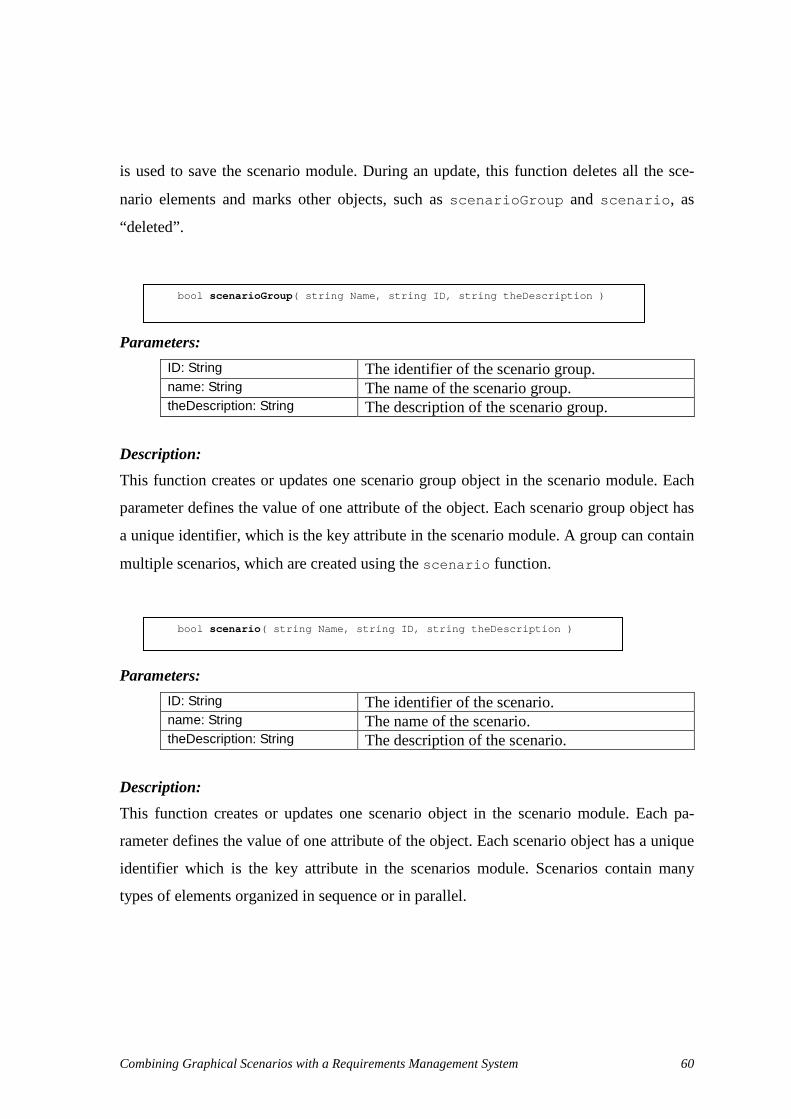
Combining Graphical Scenarios with a Requirements Management System 60
is used to save the scenario module. During an update, this function deletes all the sce-
nario elements and marks other objects, such as scenar i oGr oup and scenar i o, as
“deleted” .
Parameters:
ID: String The identifier of the scenario group. name: String The name of the scenario group. theDescription: String The description of the scenario group.
Description:
This function creates or updates one scenario group object in the scenario module. Each
parameter defines the value of one attribute of the object. Each scenario group object has
a unique identifier, which is the key attribute in the scenario module. A group can contain
multiple scenarios, which are created using the scenar i o function.
Parameters:
ID: String The identifier of the scenario. name: String The name of the scenario. theDescription: String The description of the scenario.
Description:
This function creates or updates one scenario object in the scenario module. Each pa-
rameter defines the value of one attribute of the object. Each scenario object has a unique
identifier which is the key attribute in the scenarios module. Scenarios contain many
types of elements organized in sequence or in parallel.
bool scenarioGroup( st r i ng Name, st r i ng I D, st r i ng t heDescr i pt i on )
bool scenario( st r i ng Name, st r i ng I D, st r i ng t heDescr i pt i on )

Combining Graphical Scenarios with a Requirements Management System 61
Parameters:
ID: String The identifier of the seq. parentID: String The parent of the seq.
Description:
This function creates one sequence object for the current scenario in the scenario module.
Sequence objects are not updated; they are recreated at every update. Each parameter de-
fines the value of one attribute of the object. Each sequence object has a unique identifier,
which is the key attribute in the scenario module. Sequences contain various elements
and sub-parallel sequences.
Parameters:
ID: String The identifier of the par. parentID: String The parent of the par.
Description:
This function creates one par object in the scenario module. Par objects are not updated;
they are recreated at every update. Each parameter defines the value of one attribute of
the object. Each par object has a unique identifier, which is the key attribute in the sce-
narios module. Par objects contain sub-sequences of various types of elements.
bool seq( st r i ng I D, st r i ng par ent I D )
bool par( st r i ng I D, st r i ng par ent I D )

Combining Graphical Scenarios with a Requirements Management System 62
Parameters:
ID: String The identifier of the doElement. hyperEdgeID: String The identifier of the original UCM hyperedge re-
ferred by the doElement. doType: String The type of hyperEdge referred by the doElement.
The type is one of the following: Resp, Start, End_Point, WP_Enter, WP_Leave, Con-nect_Start, Connect_End, Trigger_End, Timer_Set, Timer_Reset, or Timeout.
theDescription: String The description of the doElement. ParentID: String The identifier of the parent (seq or par) of the
doElement. Presibling: String The identifier of the previous sibling of the
doElement.
Description:
This function creates one doElement object in the scenario module. doElement objects
are not updated; they are recreated at every update. Each parameter defines the value of
one attribute of the object. Each doElement object has a unique identifier, which is the
key attribute in the scenario module. “hyperEdgeID” indicates the original UCM element
referred by the doElement. However, only one kind of hyperedge referred by doElement
objects is currently imported into the map module, namely responsibility reference. The
“hyperEdgeID” parameter for elements of type Resp hence translates to a DOORS link
from the doElement to the referred responsibility reference in the Maps folder. “paren-
tID” and “preSibling” are used to locate the position of the doElement in the scenario,
which is represented as a tree. They are not converted to DOORS links
bool doElement( st r i ng I D, st r i ng hyper EdgeI D, st r i ng Name, st r i ng doType, st r i ng t heDescr i pt i on, st r i ng par ent I D, st r i ng pr eSi bl i ng )

Combining Graphical Scenarios with a Requirements Management System 63
Parameters:
ID: String The identifier of the condition. label: String The label attached to the condition. expression: String The Boolean expression used in the selected sce-
nario branch, where the condition applied. parentID: String The identifier of the parent (seq or par) of the
condition. presibling: String The identifier of the previous sibling of the condi-
tion.
Description:
This function creates one condition object in the scenario module. Condition objects are
not updated: they are recreated at every update. Each parameter defines the value of one
attribute of the object. Each condition object has a unique identifier, which is the key at-
tribute in the scenarios module. “parentID” and “preSibling” are used to locate the posi-
tion of the condition in the scenario, which is represented as a tree. They are not con-
verted to DOORS links.
Parameters:
ucmName: String The name of the UCM model. designID: String The identifier of the UCM model.
Description:
This function is the end part of the scenario model import. It parses the created or up-
dated modules and creates links between those modules according the attributes which
contain relevant link information. For example, if the one doElement object has a value
of “hyperEdgeID” and the “doType” is “Resp”, then this function will create a link from
the doElement object to the referred responsibility reference object in the Maps folder.
Section 4.3 discusses link creation in more depth. This function also customizes the view
of the scenario module to display important object attributes which are not displayed by
default in DOORS. If the import is updating a previously model, then this function will
bool condition( st r i ng I D, st r i ng l abel , st r i ng expr essi on, st r i ng par ent I D, st r i ng pr eSi bl i ng )
bool endOfScenario( st r i ng ucmName, st r i ng desi gnI D )

Combining Graphical Scenarios with a Requirements Management System 64
remove the objects marked as “deleted” at the end of the import. Some exceptions may
occur, which are described in section 5.3.
Example After the first-time import of the scenario part of a UCM model into DOORS, the sce-
nario module is created under the Scenarios folder. A scenario view, where objects are
listed with selected attributes, is created during the import process. Figure 33 illustrates
the list of scenarios and their sequential and parallel elements and conditions (with some
of their attributes) of the Simple Telephone UCM. The tree list in the left part of the fig-
ure shows the structure of scenarios in the Simple Telephone Example. Note the triangles
on the side of some of the scenario elements; they indicate outgoing traceability links
from the scenario steps to the referred path elements traversed by this scenario. This links
information was generated automatically by our import mechanism and can be main-
tained as the UCM evolve.
Figure 33 Scenarios for the Simple Telephone System in DOORS
This section discussed the scenario library in DOORS, which supports DOORS importing
scenarios defined UCM. However, UCM models do not always contain scenarios. In
some cases, the UCM model may not contain scenarios.
Combining Graphical Scenarios with a Requirements Management System 65
4.3. Automatic Link Creation
Links are a feature of DOORS essential for creating and navigating traceability relation-
ships between requirements, which are represented as objects in formal modules. The re-
lationship between two objects in the DOORS database is established using a link. By
definition, a link goes from the source object to the target object. However, links can be
followed in either direction and DOORS provides tools that facilitate this navigation. If
an object is the target object of a link, this link is called an incoming link of the object. If
an object is the source object of a link, this link is called an outgoing link of the object.
In the proposed DOORS representation for UCMs, links are divided into internal
links and external links according to their different scopes. The links between the objects
inside the UCM model are called internal links. Otherwise, the links are called the exter-
nal links. Internal links implement the associations found in the metamodel of Figure 18.
They are created and updated automatically while importing a UCM model into DOORS.
The internal links tightly combine the three parts of the UCM model, i.e., the core, the
maps, and the scenarios. Since only internal links are created when a UCM is imported,
the discussion about external links will be left to next chapter, where links between the
imported UCM model and other requirements will be created, and analyzed, and main-
tained.
To describe precisely the nature of links, DOORS allows the definition of link at-
tributes. By taking advantage of this DOORS functionality, internal links are assigned
different types according to the various relationships between the linked UCM objects.
For example, a component can have a “hosts” link to a device, indicating the host device
of a particular component. Figure 34 gives an overview of the various types of internal
links created during the import, whereas Table 2 establishes the correspondence between
these links and the original associations from the metamodel (Figure 30). These links
help DOORS users to understand and exploit the relationships between different UCM
objects.

Combining Graphical Scenarios with a Requirements Management System 66
Figure 34 Internal links in an imported UCM model
Link type (DOORS) Source class (metamodel) Destination class (metamodel)
referring ResponsibilityReference Responsibility
referring ComponentReference Component
referring Resp ResponsibilityReference
hostedBy Component Device
requesting Responsibility Device
containedBy ResponsibilityReference ComponentReference
containedBy ComponentReference ComponentReference
Table 2 Mapping from metamodel associations to DOORS links
Through the internal links, relationships such as assignment of responsibility references
to component references, containment amongst component references, or request of re-
sponsibilities to devices can be quickly visualized and explored using existing DOORS
functionalities. DOORS uses small triangles to indicate the existence of incoming (�
) or
outgoing ( � ) links. Clicking on such triangles brings the lists of link types and their
linked objects. Links can also be exploited by queries or transformations in DXL scripts.
�����
� � � ��
� � � ��
����
� � �
� � � �� �
����� � �
����� � � � �
� � � � � � � � �
� � � �
� � � � �
����� � �
� � ��
����� � �
� � ��
����� � �
����� � �
�� � � ��� � � � �
�� ��� � � �
�� ��� � � �
� � � � � � � � � �
����� � �
�
�
�
�� ��� � � �
� � � �� � �
� � �� � � �
� � � �� � �
� � � � � � � � � �

Combining Graphical Scenarios with a Requirements Management System 67
4.4. Chapter Summary
This chapter discussed the mechanisms used to import a UCM model into DOORS for
the first time. In section 4.1, a class diagram is used to illustrate the metamodel of Use
Case Maps as represented in DOORS. Section 4.2 described the DXL library supporting
the import of UCM models into DOORS. Section 4.3 presented how the internal links
implement the associations of our metamodel, hence enabling exploration of various
UCM elements and their relationships as a whole. The next chapter will focus on evolu-
tion management by presenting how external requirements are linked to the UCM model,
how evolving requirements will be reported back to UCMNAV to update the UCM model,
and how an evolving UCM model is updated in DOORS.

Combining Graphical Scenarios with a Requirements Management System 68
Chapter 5. Managing the Evolution of Scenarios and Requirements
This chapter discusses how to manage the evolution of scenarios and requirements during
the development process. Section 5.1 presents how UCM model elements are linked to
external requirements in the target RMS. Section 5.2 shows how evolving requirements
can trigger modifications to the UCM model. Finally, section 5.3 explains how the
DOORS database is automatically updated when re-importing a new version of a UCM
model, after modifications.
5.1. Links from/to External Requirements
Having been imported into DOORS, a UCM model can be used as a supplement to exist-
ing requirements, including user requirements, system functional requirements, perform-
ance requirements, and testing requirements. Requirements engineers who are familiar
with both the UCM notation and DOORS can analyse the relationships between the
original textual requirements in DOORS and the imported UCM model, and then create
appropriate links between them. These links combine the UCM model and other textual
requirements to express more precise and complete requirements for the target system.
External links also can be used to preserve the consistency between a UCM model
and other requirements. Once requirements or the UCM model are changed, DOORS will
flag the external links connecting these two views automatically as suspect links. These
suspect links act as change notifications for the requirements. These proactive suspect
links ensure that each user knows about changes made by another user.
In practice, links could be created between external requirements and any object
in the imported UCM model. However, DOORS users are encouraged to create links only
to objects in a UCM model that are automatically maintained during the import. Some of
the objects, although they are part of the UCM model, are deleted and recreated at each

Combining Graphical Scenarios with a Requirements Management System 69
import. This is the case for all the elements composing scenarios (par, seq, doElements,
and conditions). Hence, links should not be created from/to these objects.
Guidelines to create external links from/to the UCM model
• Component references and responsibility references represent specific usages of
elements part of the system structure and behaviour. Most parts of system re-
quirements can be linked to component references or responsibility references in
the UCM model.
• A map is used to describe a system or a sub-system including its structure and
behaviour. It can be considered as a visual use case. Therefore, it could be linked
to a functional requirement or to a use case in the user requirements.
• A stub is often used for the decomposition of the UCM model. It is a reference to
sub-systems. Dynamic stubs could be used for a product family. Requirements
should not be linked to a static stub directly. Instead, it is suggested to link re-
quirements to the corresponding map referred by the stub.
• Components and responsibilities are used to describe specific elements of the sys-
tem structure and behaviour. References to these elements can appear in many
places in a UCM model. Links from system requirements are encouraged, but not
to/from user requirements.
• If a requirement is related to a performance resource such as a processor, a disk,
or another type of service in a system and the resource is described as a device in
the UCM model, then a link between the requirement and the corresponding de-
vice should be created.
• Regarding test requirements, related test cases could be grouped as test suites and
linked to the corresponding scenario group in the UCM model.
• Scenarios in the UCM model could be linked to the related functional require-
ments or from test goals for the target system. However, individual scenario step
should not be linked to external requirements or test steps because a scenario is
usually viewed as a unit of functional requirement or a test goal and should not be
broken up. If a requirement is related to a system action during the scenario path,
it should be linked to the responsibility reference referred by that scenario step.

Combining Graphical Scenarios with a Requirements Management System 70
• Links are usually created from requirements to higher-level requirements (e.g.,
from system requirements to user requirements). That is the model supported by
the link access policy in DOORS: a user must have “Read” and “Modify” access
rights at the source object in order to create a link. In most cases, the higher-level
requirements are read-only to the UCM modellers. Since UCM modellers must
have “Modify” access right to in order to create a link, they can only create links
from the UCM model, where they have write access, to the higher-level require-
ments. Therefore, the default type of links created between the UCM model and
external requirements are “Satisfies” .
• The UCM modellers are not encouraged to created links from the UCM objects to
lower level requirements. All of the links in the project should follow in the same
direction for traceability analysis purpose, which is bottom up in our case. There-
fore, “Satisfies” links should be created from lower level requirements to the
UCM model by whoever is responsible of those lower level requirements.
Following these guidelines, a UCM model should be linked to higher-level requirements
such as user requirements. It also can be linked from system requirements and functional
tests requirements as shown in Figure 35.
Figure 35 Links between a UCM model and external requirements
Userrequirements
UCM ModelIn DOORS
System requirements
Functionaltests
Satisfies
Satisf iesSatisf iesUserrequirements
UCM ModelIn DOORS
System requirements
Functionaltests
Satisfies
Satisf iesSatisf ies

Combining Graphical Scenarios with a Requirements Management System 71
5.2. Evolving UCM Models According to Changed Requirements
Requirements are very likely to be changed during the development process. This section
discusses how to evolve the UCM model when its linked requirements are modified in
the RMS.
In general, once a requirement is changed, lower level requirements (e.g., at the
software level) that are linked to it should be checked and kept consistent with its new
version. Furthermore, higher-level requirements (e.g., at the user level) that are linked
from it also need be checked for satisfaction. People may argue the higher-level require-
ments do not have to be checked because a requirement should always be consistent with
its higher-level requirements when it is changed. That argument is based on the assump-
tion that the maintainer of the requirement understood the higher-level requirements cor-
rectly. However, since requirements are expressed in nature language and may be created
by different people, maintainers may have different understandings of the same require-
ment. This drawback of requirements expressed in nature language encouraged many
people to advocate in favour of formal requirements specification, which are outside the
scope of this thesis. Another reason to check higher-level requirements is that the latter
may be refined and clarified when creating or updating lower level requirements.
Tracking the traceability between various requirements and keeping them consis-
tent has always been a difficult requirements management issue. As mentioned in sec-
tion 4.3, requirements management systems use links to manage requirements evolution.
As discussed in the last section, a UCM model could be linked to and from various re-
quirements such as user, test, and system requirements. If user requirements are changed
after some refinements, e.g., resulting from further communications with customers or
other stakeholders, the linked UCM objects will be triggered as having suspect outgoing
links by the RMS. If lower level requirements, such as test requirements or system re-
quirements, are refined, then the changes may have an impact on the linked UCM objects.
From the UCM point of view, the links between them will be triggered as suspect in-
coming links. The suspect links, including incoming and outgoing links, indicate the
UCM objects that need to be verified according to the changed requirements, and
changed if necessary. In the DOORS representation of the UCM model, suspect links are

Combining Graphical Scenarios with a Requirements Management System 72
defined as attributes in the pre-defined views customized by the import process, as shown
in Figure 36.
Figure 36 Suspect links between a UCM model and external requirements
5.2.1 Generating the Changed Requirements from DOORS
If the linked external requirements are changed, the UCM model should be verified and
may need to be modified to match the new requirements. However, the UCM model
should not be modified from DOORS. The approach described in this thesis does not im-
plement a UCM editor in DOORS as such functionality is best supported in an external
tool like UCMNAV. Therefore, modifications need to be done outside of DOORS, in
UCMNAV.
To provide guidance in the update of the UCM model, a report is generated by
DOORS that emphasizes detailed information about the changed requirements and their
related UCM objects. Our approach provides an automated report generation function
implemented in DXL.
The report function is available from a new menu item in DOORS, which appears
in all the views. This function parses all the UCM objects in the current project. For those
UCM objects with suspect links, the report function extract their names, types, identifiers,
suspect link types, old object content and new object content as shown in Figure 37. All
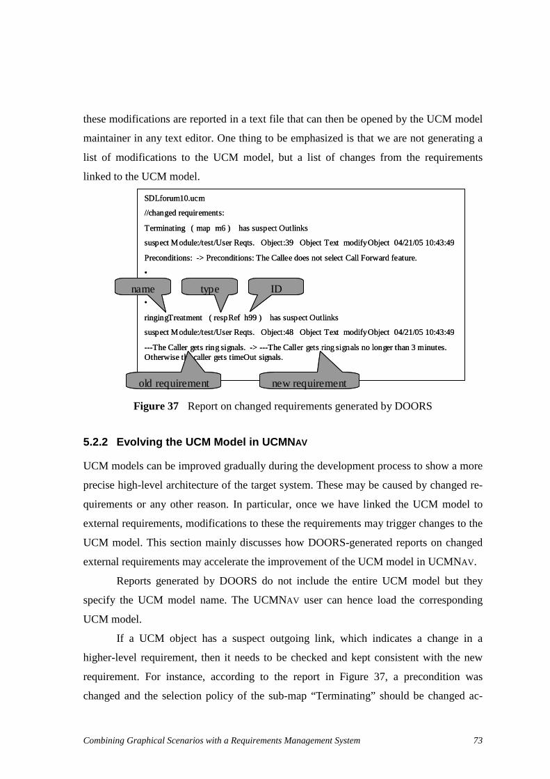
Combining Graphical Scenarios with a Requirements Management System 73
these modifications are reported in a text file that can then be opened by the UCM model
maintainer in any text editor. One thing to be emphasized is that we are not generating a
list of modifications to the UCM model, but a list of changes from the requirements
linked to the UCM model.
Figure 37 Report on changed requirements generated by DOORS
5.2.2 Evolving the UCM Model in UCMNAV
UCM models can be improved gradually during the development process to show a more
precise high-level architecture of the target system. These may be caused by changed re-
quirements or any other reason. In particular, once we have linked the UCM model to
external requirements, modifications to these the requirements may trigger changes to the
UCM model. This section mainly discusses how DOORS-generated reports on changed
external requirements may accelerate the improvement of the UCM model in UCMNAV.
Reports generated by DOORS do not include the entire UCM model but they
specify the UCM model name. The UCMNAV user can hence load the corresponding
UCM model.
If a UCM object has a suspect outgoing link, which indicates a change in a
higher-level requirement, then it needs to be checked and kept consistent with the new
requirement. For instance, according to the report in Figure 37, a precondition was
changed and the selection policy of the sub-map “Terminating” should be changed ac-
SDLforum10.ucm
//changed requirements:
Terminating ( map m6 ) has suspect Outlinks
suspect M odule:/test/User Reqts. Object:39 Object Text modifyObject 04/21/05 10:43:49
Preconditions: -> Preconditions: TheCalleedoes not select Call Forward feature.
•
•
•
ringingTreatment ( respRef h99 ) has suspect Outlinks
suspect M odule:/test/User Reqts. Object:48 Object Text modifyObject 04/21/05 10:43:49
---The Caller gets ring signals. -> ---The Caller gets ring signals no longer than 3 minutes. Otherwise the caller gets timeOut signals.
name type ID
old requirement new requirement

Combining Graphical Scenarios with a Requirements Management System 74
cordingly. Also, the requirement of the responsibility “ ringingTreatment” has been
changed to “The Caller gets ring signals no longer than 3 minutes. Otherwise the caller
gets timeout Signals” instead of “The caller gets ring signals” . Therefore, a timer is added
before “ ringingTreatment” , the timeout exception sends “TimeOut” signals to both the
caller and the callee through “ ringTimeOutTreament” .
Figure 38 The modified UCM model
If a UCM object has a suspect incoming link, which indicates a changed in a lower-level
requirement, then the UCMNAV user needs to check that the updated requirement still
satisfies the UCM. If this is the case, then no action is required on the UCM model. Oth-
erwise, if the updated requirement clarifies the UCM object, then the UCM model should
be refined accordingly, or else the user who modified the linked requirement needs to be
informed of the inconsistency.
5.3. Evolving the DOORS View According to Changed UCM
The last section discussed how the UCM model can evolve during the developing process.
New versions of the UCM model can be saved in different files, if desired, to preserve the
history of modifications. However, the identifier of the UCM model, the design name,
will remain unchanged in each version, which ensures the right UCM model in DOORS
will be updated. The new version of the UCM model can be re-exported to DOORS
through the DXL script generated from UCMNAV. The DXL script may use a new file
name according to the new version of the UCM model. This section explains how an ex-
isting UCM model in DOORS is updated while executing the new DXL script.
busyTreatment
ringingTreatment
start
success
fail
[notBusy] IN1
[Busy]
reportSuccess
OUT2 disp
ringTreatmentOUT1ringing
TimeOutringTimeOutTreatment
Sdisplay
Combining Graphical Scenarios with a Requirements Management System 75
5.3.1 Algorithm for Managing Evolving UCM Elements
When the new DXL script is loading and executing in DOORS, the UCM model is up-
dated in DOORS according to the following algorithm, which is composed of four steps:
Step 1: Pre-process the UCM model.
Before updating concrete objects, some pre-processing needs be performed on the exist-
ing UCM model:
• Remove internal links inside the UCM model. Internal links shows the relation-
ships between the UCM objects. In the update process, internal links may affect
the updating of UCM objects due to a restriction when deleting an object in
DOORS: an object cannot be deleted when it has an incoming link. This restric-
tion prevents a requirement object from being deleted when there are other re-
quirements “depending” on it. For instance, if one component in the UCM model
has some incoming links from some structure objects in the system requirement,
which provides more detailed information about the component, then it cannot be
deleted. Otherwise, those structure objects in the system requirement would be-
come irrelevant to upper-level requirements. Fortunately, we have total control
over the links between the UCM model elements, and they can hence safely be
removed.
• Delete all the scenario steps, such as seq, par, doElement, condition. They are
always recreated at each update. The reason to do this pre-processing is that sce-
nario steps do not exist as individual requirements but describe bits and pieces of
one requirement: a scenario. Moreover, changes of scenario steps can be tremen-
dous at each update. For instance, if one a scenario step is changed, then all the
following scenario steps will be affected. Links from external requirements
should be created to scenarios, not to their steps.
• Set the “ deleted” attribute of all UCM objects to “ true” . DOORS does not pro-
vide a function to recognize the objects that should be removed after having up-
dated the UCM model. The update process proposed here uses an additional Boo-
lean attribute deleted for determining the status of UCM objects.

Combining Graphical Scenarios with a Requirements Management System 76
Step 2: Update UCM objects.
After having pre-processed the existing UCM model in the DOORS database, the update
process loads and executes DXL function calls for elements from the new version of the
UCM model. For each object listed in the DXL script, the updating process searches the
UCM model using the value of the key attribute which is unique in the UCM model. If
the object is found in the existing UCM model, the values of its attributes are compared
with the corresponding parameters in the function call for this object. All relevant attrib-
utes with different values are updated. Then the deleted attribute is changed to false. If
the object listed in the DXL script is not found in the existing UCM model, then a new
object will be created with all the attributes defined in the DXL script. The default value
of the deleted attribute in new UCM object is false. The deleted attribute is used to record
the status of UCM objects by the update process.
Some of the attributes of UCM objects record their position information in a dia-
gram or other information not so relevant from a requirements viewpoint (see Table 3).
Changed values for these attributes will not affect the modification history of the UCM
object, trigger suspect links to linked requirements, or change the notification bar in the
UCM module.
Modules Attributes
Core Device Component Maps Scenarios
Deleted hasIncomingLink
Deleted hasIncomingLink
Deleted hasIncomingLink
Deleted hasIncomingLink fx fy width height direction stubType
Deleted hasIncomingLink
Table 3 Attributes not affecting histories, suspect links, and the notification bar
Step 3: Remove objects that have disappeared in the new UCM model.
After all the new objects in the DXL script have been imported into the DOORS database,
a post-processing step is performed. The deleted attribute of all the UCM objects in
DOORS will be checked. The “deleted” objects (where the value is true) without incom-
ing links are removed from the UCM model. The “deleted” objects with incoming links
cannot be deleted due to the restriction in DOORS. Their hasIncomingLink attribute is
however set to true during the update process. Their on-empty set of incoming links in-

Combining Graphical Scenarios with a Requirements Management System 77
dicates that some lower-level requirements depend on them. The UCM model user may
inform the requirements manager of those lower-level requirements and request the re-
moval of the links between those lower-level requirements and the “deleted” UCM ob-
jects. Once those links are removed, the UCM model manager can eliminate “deleted”
objects manually.
Step 4: Create internal links
This step is concerned with the creation of internal links between the related UCM ob-
jects according to their association attributes. Adding or removing internal links does not
trigger suspect links to/from external requirements because DOORS does not consider
them as major changes to requirements.
As mentioned in section 4.1, the composition relationships between UCM objects
are represented by containment relationships between the DOORS database objects. If
there is a parent-child relationship between an updated UCM object and its parent UCM
object, then the updating process does not have to verify whether the relationship is
changed or not. That is due to the fact that UCMNAV does not provide a mechanism to
move objects to other hosting objects. For instance, a component reference cannot be
moved to another map. Also, a scenario cannot be moved to another scenario group.
5.3.2 Managing Evolving UCM Links with External Requirements
As mentioned in section 5.2, modifications to external requirements cause suspect links
in the linked UCM objects. Some UCM objects with suspect links are very likely to re-
quire some changes in a new iteration of the development cycle. When they are
re-imported into DOORS, their new description will clear their suspect links. In DOORS,
changing one requirement will cause its linked requirements to have suspect links. If its
linked requirements are modified after getting suspect links, then these suspect links will
be cleared. The update process may also update some UCM objects without suspect links.
If these objects have external links to/from other requirements, then their new description
will cause suspect links in their linked requirements, which in turn will suggest that the
external requirements should be revisited.

Combining Graphical Scenarios with a Requirements Management System 78
5.4. Chapter Summary
This chapter presented how UCMs are linked with other requirements in the RMS and
how their inter-dependencies can be managed as they evolve. Since UCMs are introduced
into the RMS as traceable objects, they can be connected with various external require-
ments through different types of links. Principles for creating useful links were mainly
discussed in section 5.1. In section 5.2, we introduced a report mechanism for the RMS
which summarizes changed requirements in order to promote the evolution of the UCM
model. Section 5.3 described an algorithm for updating UCMs in the RMS and discussed
the impact to the existing requirements during the update process. The next chapter will
illustrate and validate the approach from end-to-end with a supply chain management
case study.
Combining Graphical Scenarios with a Requirements Management System 79
Chapter 6. Case Study: Supply Chain Management
In this chapter, our approach is applied to and validated against a Web Services Interop-
erability (WS-I) case study, which contains a Supply Chain Management (SCM) business
process [36][37]. Our case study illustrates how our approach can improve the overall
quality of requirements management by introducing a UCM model into the target RMS
and, more importantly, how both views can be kept complete and consistent as they
evolve. The UCM model used in chapter is based on the model created by Weiss and
Amyot [38][39].
SCM models a retailer system that offers goods to consumers. To fulfill orders, the
retailer has to manage stock levels in its warehouses. When an item in stock falls below a
certain threshold, the retailer must restock the item from the relevant manufacturer’s in-
ventory. In order to fulfill a retailer’s request, a manufacturer may have to execute a pro-
duction run to build the finished goods [36].
In section 6.1, initial informal requirements are provided for SCM. Then a UCM
model for SCM is created and exported to the RMS in section 6.2. Section 6.3 presents
how changes to the UCM model affect the RMS database and links to other related re-
quirements. Section 6.4 describes how the UCM model is in turn affected by changes to
related requirements in the RMS. A discussion of the main benefits and a comparison
with existing tools follow in section 6.5.
6.1. Initial Requirements for SCM
In this case study, user requirements, system requirements and test requirements are used
to describe the supply chain management system in the target RMS. They are adapted
and simplified from the requirements listed in [36][37]. In general, requirements man-
agement systems can import requirements from various sources, including word proces-
sors. For instance, we can import the original SCM requirements into DOORS, leading to
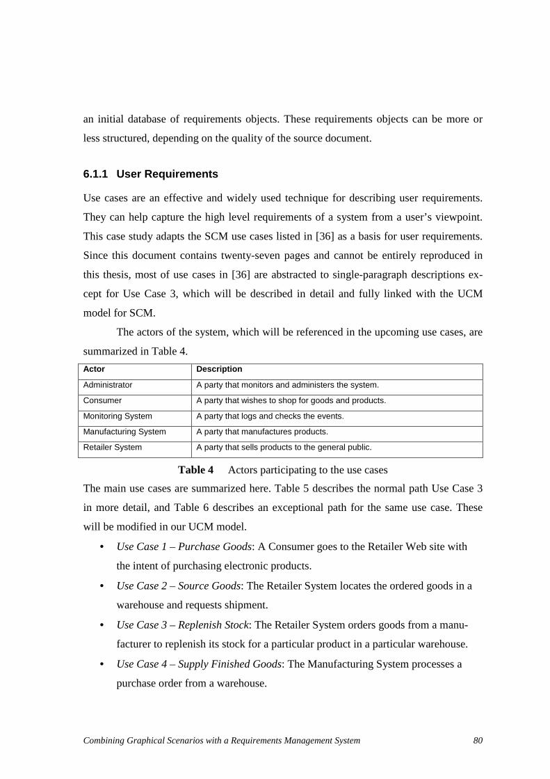
Combining Graphical Scenarios with a Requirements Management System 80
an initial database of requirements objects. These requirements objects can be more or
less structured, depending on the quality of the source document.
6.1.1 User Requirements
Use cases are an effective and widely used technique for describing user requirements.
They can help capture the high level requirements of a system from a user’s viewpoint.
This case study adapts the SCM use cases listed in [36] as a basis for user requirements.
Since this document contains twenty-seven pages and cannot be entirely reproduced in
this thesis, most of use cases in [36] are abstracted to single-paragraph descriptions ex-
cept for Use Case 3, which will be described in detail and fully linked with the UCM
model for SCM.
The actors of the system, which will be referenced in the upcoming use cases, are
summarized in Table 4.
Actor Description
Administrator A party that monitors and administers the system.
Consumer A party that wishes to shop for goods and products.
Monitoring System A party that logs and checks the events.
Manufacturing System A party that manufactures products.
Retailer System A party that sells products to the general public.
Table 4 Actors participating to the use cases
The main use cases are summarized here. Table 5 describes the normal path Use Case 3
in more detail, and Table 6 describes an exceptional path for the same use case. These
will be modified in our UCM model.
• Use Case 1 – Purchase Goods: A Consumer goes to the Retailer Web site with
the intent of purchasing electronic products.
• Use Case 2 – Source Goods: The Retailer System locates the ordered goods in a
warehouse and requests shipment.
• Use Case 3 – Replenish Stock: The Retailer System orders goods from a manu-
facturer to replenish its stock for a particular product in a particular warehouse.
• Use Case 4 – Supply Finished Goods: The Manufacturing System processes a
purchase order from a warehouse.

Combining Graphical Scenarios with a Requirements Management System 81
• Use Case 5 – Manufacture Finished Goods: The Manufacturing System initiates a
production run to replenish the stock levels of a specified product.
• Use Case 6 – Log Events: The Monitoring System logs events related to the exe-
cution of other use cases.
• Use Case 7 – View Events: The Administrator views the event logs by setting
certain criteria.
Step Actor Description Branches Condition Location
1. Retailer System
The Retailer System constructs a purchase order for the product with the necessary quantity to bring the product up to its maximum level for that ware-house.
2. Retailer System
Place Order. The Retailer system submits the pur-chase order to the relevant Manufacturing System (Brand1, Brand2 or Brand3) as dictated by the product.
3. Manufacturing System
Validate Order. Malformed order or invalid product or invalid quan-tity
ALT 1
4. Manufacturing System
Send an acknowledgement back to the Retailer System.
5. Manufacturing System
The Manufacturing System constructs a shipment of the requested quantity of product.
Uncondi-tional
Use Case 4
6. Manufacturing System
The Manufacturing System ships the goods and sends a shipping notice to the warehouse. The shipping notice is the business level reply to the purchase order.
7. Retailer System
When the Retailer System receives the shipping notice, an acknowledgement is sent back to the Manufacture.
8. Retailer System
Upon receipt of the shipment, the warehouse up-dates its product inventory level based on receipt of the shipped order.
Table 5 Primary path of Use Case 3

Combining Graphical Scenarios with a Requirements Management System 82
Table 6 Exception path of Use Case 3
6.1.2 System Requirements
The system requirements used in this case study are not component-based. Detailed ar-
chitecture information is not provided. It mainly describes what functions the SCM sys-
tem should provide.
The entire system requirements are listed in Appendix A. Since in our example
we plan to apply changes to the Replenish Stock functionality in the UCM model, system
requirements related to Replenish Stock are listed in Table 7.
System Requirements
Retailer System The warehouse should be able to build the order for a manufacturer.
Retailer System The warehouse should be able to select the appropriate manufacturer.
Retailer System The warehouse should be able to place the order to the selected manufacturer.
Retailer System The warehouse should be able to receive the products shipped by the manufacturer.
Retailer System The warehouse should be able to update its stock upon receipts of goods.
Retailer System The warehouse should be able to send acknowledgement back to the manufacturer after receiving goods.
Retailer System The warehouse should be able to determine the replenishment is time out or not.
Table 7 Functional requirements related with Use Case 3: Replenish Stock
6.1.3 Test Requirements
Test requirements contain test cases and test scenarios whose goal is to validate the SCM
system. They are adapted from the validation scenarios defined in [38][39]. To simplify
the test requirements, concrete steps in validation scenarios are not provided in Table 8
since they will not be linked to scenarios in the UCM model.
Step Actor Description Branches Condition Location
1. Manufacturing System
The Manufacturing System rejects the order either due to a malformed order, a request for a product that does not exist, or a request for an invalid quantity (e.g. zero or more than the max level for that product). A reply, containing an application error message, is sent back to the Retailer System.

Combining Graphical Scenarios with a Requirements Management System 83
Test Case and Validation Scenario Description
Test Group 1: RejectOrder The product order gets rejected (because the product does not exist or because none of the goods can be found in any of the warehouses).
ProductDoesNotExist The order is rejected because the product does not exist.
InsufficientStock1WH1Item The order is rejected because the desired quantity of goods is not available in the single warehouse.
InsufficientStock1WH2Items The order is rejected because the warehouse has insufficient stocks for all the desired products.
InsufficientStock2WH1Item The order is rejected because none of the warehouses have suf-ficient quantities of the desired product. T
est C
ases
InsufficientStock2WH2Items The order is rejected because none of the warehouses has suffi-cient stocks for any of the desired products.
Test Group 2: ShipmentConfirmed Tests where the shipment is done.
PrimaryScenario The warehouse has the desired item.
ShipmentWithReplenish-mentSuffInv
The warehouse has the desired item. Replenishment with suffi-cient inventory.
ShipmentCannotReplen-ishInvalidOrder
The warehouse has the desired item. However, during replen-ishment, the order is judged invalid.
ShipmentWithReplenish-mentInsuffInv
The warehouse has the desired item. During replenishment, the inventory is insufficient and manufacturing gets involved. T
est C
ases
ShipmentByNextWarehouse The first warehouse has insufficient stocks but the second one provides the shipment.
Test Group 3:PeriodicReplenishment Tests for the periodic replenishment architectural alternative.
StopRightAway The periodic replenishment is stopped right away.
CheckButStocksSufficient The periodic replenishment is checked but stocks are sufficient.
CheckAndStockInsufficient The periodic replenishment is checked and stocks need to be increased. The order is valid and the inventory is sufficient.
CheckAndStockInventory-Insufficient
The periodic replenishment is checked and stocks need to be increased. The order is valid and the inventory is insufficient.
Tes
t Cas
es
CheckAndStockInsuffi-cientInvalidOrder
The periodic replenishment is checked and stocks need to be increased. The order is however invalid (malformed. invalid product or invalid quantity).
Test Group 4: ViewEvents Scenarios for the viewing of the events log.
CanAccessLog The request for viewing the events is valid and the relevant events are listed.
CannotAccessLog The request for viewing the events is invalid.
Test Group 5: LogRequests Scenarios checking the event log mechanism.
EventLogged Primary scenario where the event is logged.
InvalidLogRequest The event log request is invalid and denied.
InvalidLogRequestNoRepo The event log request is invalid. The system attempts to log the request but cannot because the repository is unavailable.
Tes
t Cas
es
ValidLogRequestNoRepo The valid log request fails because the repository is unavailable.
Table 8 Test cases for SCM (adapted from [38])

Combining Graphical Scenarios with a Requirements Management System 84
6.2. UCM Model for SCM
This case study takes advantage of the UCM model defined in [39] and adapts it to the
UCM model for SCM, based on user requirements described in 6.1.1. The UCM model
for SCM is created using our modified version of UCMNAV. Then it is exported as a
DXL script by using the new feature of UCMNAV discussed in Chapter 3. The DXL
script is interpreted and executed to create the UCM model for SCM in DOORS, using
the DXL library discussed in Chapter 4. The initial UCM model for SCM in DOORS is
shown (in part) in Figure 39 and Figure 40, whereas the complete model can be found in
Appendix C.
Figure 39 shows the UCM maps for SCM, as seen from DOORS. On the left side,
a tree-like explorer provides the view for the structure of the map module and for navi-
gating to a specific object in the module. UCM map objects are shown in the right panel.
They can be displayed in different views where we can customize different sorts, attrib-
utes, and filters for the displayed objects. The Map column shows diagrams for UCM
maps as well as the names of the objects they contain. The Type column indicates the ob-
ject types. For objects having links to/from objects in other modules, DOORS also pro-
vides the facility to display information about their traced objects. Thus, the Referred
Component column is used to display the linked components from the core module for
compRef objects in the maps module. In the same way, the column Referred Responsi-
bilities displays names of the linked responsibilities from the core module.

Combining Graphical Scenarios with a Requirements Management System 85
Figure 39 UCM maps for SCM
UCM scenarios for SCM are shown in Figure 40. As this is the initial UCM model for
SCM, only internal links are created between UCM objects.
Figure 40 UCM scenarios for SCM

Combining Graphical Scenarios with a Requirements Management System 86
After being imported into DOORS, the UCM model elements need be linked to user re-
quirements and from system requirements. In this case study, UCM maps and component
reference under them are linked to the matching Use Case in the user requirements. Re-
sponsibility references are linked to concrete steps in a Use Case. Each piece of system
requirements is linked to the corresponding responsibility reference in UCM maps.
By using the traceability column feature provided by DOORS, a traceability view
can be used in the user requirements module to show relationships to UCM maps and,
indirectly, to system requirements (Figure 41). For each user requirement, the traceability
view shows the information about objects in UCM maps (column UCM Requirements)
that are linked to it. In the same way, system requirements that link to UCM objects are
shown in column System Requirements.
Figure 41 Traceability view from user requirements
The imported UCM scenarios are also linked from test cases in test requirements as
shown in Figure 42. Column “ In-links from Test Cases” indicates the test case or test
group which describes the linked scenario or scenario group. Note that concrete scenario
steps are hidden in the traceability view in Figure 42 by specifying a filter.

Combining Graphical Scenarios with a Requirements Management System 87
Figure 42 Scenarios traceability view
After creating links between the UCM model and external requirements, user require-
ments, system requirements, and test requirements of are connected through the UCM
model with relations shown in Figure 35. By exploring links between them, the com-
pleteness and consistency of requirements can be checked. For instance, UCM maps can
be validated against their linked use cases and system requirements, as shown in Figure
41, as well as UCM scenarios being validated against their linked test cases as shown in
Figure 42.
Links can be used as filter conditions to find out isolated requirements. For exam-
ple, in our first version of the UCM model, the map periodic replenishment and its ob-
jects have no links to user requirements. This is detected by applying the following filter
condition to the map module: Not (Has out-links through /WSI-link with
reqts./maps/satisfies)). This could become a reason to remove the map periodic replen-
ishment in the next version of the UCM model. Also, the use cases “Log Events” and
“View Events” from the user requirements have no support in the UCM model. This can
be detected by applying the following filter condition: Not (Has in-links through
/WSI-link with reqts./maps/satisfies). This could justify the addition of new maps for
these two use cases in the next version of the UCM model.

Combining Graphical Scenarios with a Requirements Management System 88
6.3. Managing Changes to the UCM Model
As we discussed in last section, validating the first version of the UCM model for SCM
to other requirements may lead to the detection of incomplete UCM models and incon-
sistencies with other requirements. This (or other reasons) can be a start point for the next
version of the UCM model. Once the UCM model is modified in UCMNAV, a new DXL
script is generated to update the UCM model in DOORS. This section uses a new version
of the UCM model for SCM to validate the update mechanism discussed in section 5.3.
The following changes in Table 9 are applied on the first UCM model for SCM to
obtain the second version. They cover the addition, modification, and deletion of objects
and attributes from the Core, Maps, and Scenarios packages in the metamodel.
Core Maps Scenarios
Add Responsibility: ValLogRequest LogToRepository LogInvalidRequest EnterCriteria ValidateRequest
Component: MonitoringSystem Administrator
LogEventsRoot (Map): ValLogRequest (respRef) LogToRepository (respRef) LogInvalidRequest (respRef) MonitoringSystem (compRef)
ViewEventsRoot(Map): EnterCriteria (respRef) ValidateRequest (respRef) MonitoringSystem (compRef) Administrator (compRef)
ViewEvents: CanAccessLog CannotAccessLog
LogRequests: EventLogged InvalidLogRequest InvalidLogRequestNoRepo ValidLogRequestNoRepo
Modify Change speed factor of ConsumerProc (Device) from 2 to 1
ReplenishStock(Map): Move PlaceOrder (respRef) from Manufacturer (compRef) to Ware-house (compRef)
Rename Build(respRef) to Buil-dOrder and change description
Move ValidateWHorder(respRef) position within same component.
Move SelectManufacturer(respRef) position within same component.
Change the description of Pri-maryScenario (Scenario) in ShipmentConfirmed (Sce-narioGroup)
Delete Responsibility: TEST-Timeout
PeriodicReplenishment (Map): TEST-Timeout (respRef) Replenishment (Stub) Warehouse (compRef)
PeriodicReplenishment: StopRightAway CheckButStocksSufficient CheckAndStockInsufficient CheckAndStockInventory-Insufficient CheckAndStockInsuffi-cientInvalidOrder
Table 9 Changes applied on the first UCM model for SCM

Combining Graphical Scenarios with a Requirements Management System 89
The rest of this section will present the new UCM model after applying the changes listed
in Table 9, including its interactions with other requirements.
6.3.1 Addition of New Maps and Core Elements
As shown in Figure 43, maps LogEventsRoot and ViewEventsRoot were added into the
map module for SCM, including responsibility references and component references un-
der them. Referred components and responsibilities are also listed in traceability columns
New Components in core and New Responsibilities in core. Only new objects in the map
module are shown in Figure 43 by applying a filter to select objects having no links
to/from external requirements.
Figure 43 New maps and core elements
6.3.2 Addition of New Scenarios
New scenario groups and their scenarios were added to the scenario module in the UCM
model for SCM, as shown in Figure 44. Scenarios with links from test requirements and

Combining Graphical Scenarios with a Requirements Management System 90
concrete steps of new scenarios are filtered out by defining a filter for the scenario mod-
ule view. This provides a clear view focusing on new scenarios in the scenario module.
Figure 44 New scenarios after the update
New UCM maps, core elements, and scenarios added into the UCM model are isolated
with respect to other requirements. They have to be linked manually with external re-
quirements. The traceability view in Figure 45 shows that new links were created from
system requirements to use cases through the new UCM maps. Test requirements should
also be linked to the new UCM scenarios.

Combining Graphical Scenarios with a Requirements Management System 91
Figure 45 Adding links between new UCM maps to/from external requirements
6.3.3 Deletion of Maps
Map PeriodicReplenishment and its objects should be removed from the map module
while importing the new version of the UCM model. However, exceptions were gener-
ated during the update process. A responsibility reference TEST-Timeout cannot be de-
leted by the update process because it has an incoming link from one system requirement,
which indicates that this system requirement depends on it. Map PeriodicReplenishment
also cannot be deleted because its child TEST-Timeout still exists. The update process of
the UCM model reports these problems in an exception view, as shown in Figure 46. To
remove these two objects in the report, the link between TEST-Timeout and system re-
quirements needs to be manually removed first. Then TEST-Timeout and its parent map
can be deleted, either manually or by re-executing the update process.

Combining Graphical Scenarios with a Requirements Management System 92
Figure 46 Exceptions generated while deleting maps
6.3.4 Deletion of Scenarios
In Figure 47, the scenario group PeriodicReplenishment and its contained scenarios are
also reported as “Can’ t delete” by the update function, as indicated by the column of the
same name. They have incoming links from test cases in the test requirements. To re-
move them, links from the test requirements need to be removed first.
Figure 47 Exceptions generated while deleting scenarios
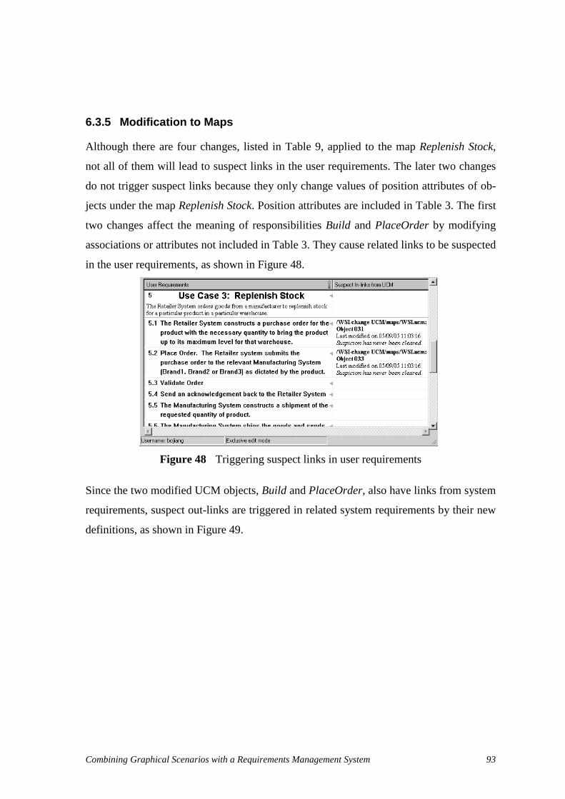
Combining Graphical Scenarios with a Requirements Management System 93
6.3.5 Modification to Maps
Although there are four changes, listed in Table 9, applied to the map Replenish Stock,
not all of them will lead to suspect links in the user requirements. The later two changes
do not trigger suspect links because they only change values of position attributes of ob-
jects under the map Replenish Stock. Position attributes are included in Table 3. The first
two changes affect the meaning of responsibilities Build and PlaceOrder by modifying
associations or attributes not included in Table 3. They cause related links to be suspected
in the user requirements, as shown in Figure 48.
Figure 48 Triggering suspect links in user requirements
Since the two modified UCM objects, Build and PlaceOrder, also have links from system
requirements, suspect out-links are triggered in related system requirements by their new
definitions, as shown in Figure 49.
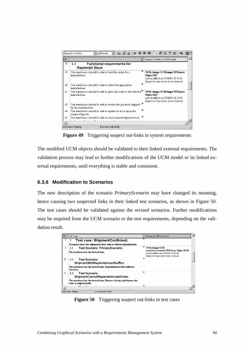
Combining Graphical Scenarios with a Requirements Management System 94
Figure 49 Triggering suspect out-links in system requirements
The modified UCM objects should be validated to their linked external requirements. The
validation process may lead to further modifications of the UCM model or its linked ex-
ternal requirements, until everything is stable and consistent.
6.3.6 Modification to Scenarios
The new description of the scenario PrimaryScenario may have changed its meaning,
hence causing two suspected links in their linked test scenarios, as shown in Figure 50.
The test cases should be validated against the revised scenarios. Further modifications
may be required from the UCM scenario or the test requirements, depending on the vali-
dation result.
Figure 50 Triggering suspect out-links in test cases
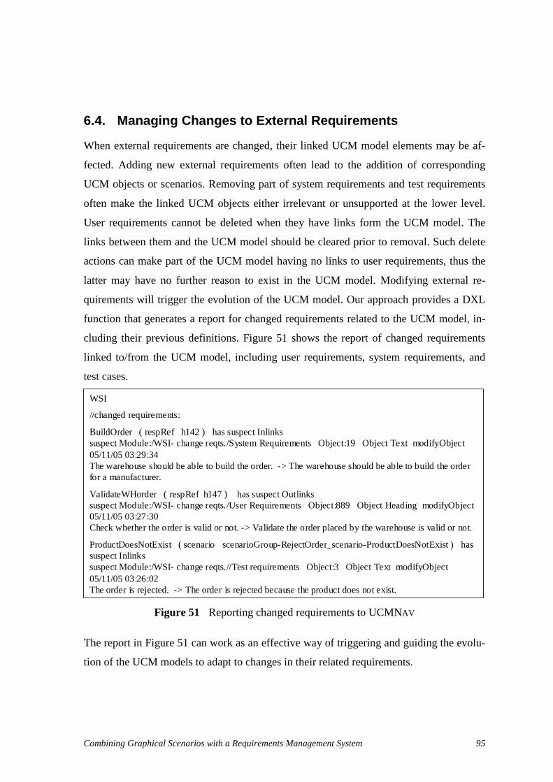
Combining Graphical Scenarios with a Requirements Management System 95
6.4. Managing Changes to External Requirements
When external requirements are changed, their linked UCM model elements may be af-
fected. Adding new external requirements often lead to the addition of corresponding
UCM objects or scenarios. Removing part of system requirements and test requirements
often make the linked UCM objects either irrelevant or unsupported at the lower level.
User requirements cannot be deleted when they have links form the UCM model. The
links between them and the UCM model should be cleared prior to removal. Such delete
actions can make part of the UCM model having no links to user requirements, thus the
latter may have no further reason to exist in the UCM model. Modifying external re-
quirements will trigger the evolution of the UCM model. Our approach provides a DXL
function that generates a report for changed requirements related to the UCM model, in-
cluding their previous definitions. Figure 51 shows the report of changed requirements
linked to/from the UCM model, including user requirements, system requirements, and
test cases.
Figure 51 Reporting changed requirements to UCMNAV
The report in Figure 51 can work as an effective way of triggering and guiding the evolu-
tion of the UCM models to adapt to changes in their related requirements.
WSI
//changed requirements:
BuildOrder ( respRef h142 ) has suspect Inlinkssuspect Module:/WSI- change reqts./System Requirements Object:19 Object Text modifyObject05/11/05 03:29:34The warehouse should be able to build the order. -> The warehouse should be able to build the order for a manufacturer.
ValidateWHorder ( respRef h147 ) has suspect Outlinkssuspect Module:/WSI- change reqts./User Requirements Object:889 Object Heading modifyObject05/11/05 03:27:30Check whether the order is valid or not. -> Validate the order placed by the warehouse is valid or not.
ProductDoesNotExist ( scenario scenarioGroup-RejectOrder_scenario-ProductDoesNotExist ) has suspect Inlinkssuspect Module:/WSI- change reqts.//Test requirements Object:3 Object Text modifyObject05/11/05 03:26:02The order is rejected. -> The order is rejected because the product does not exist.
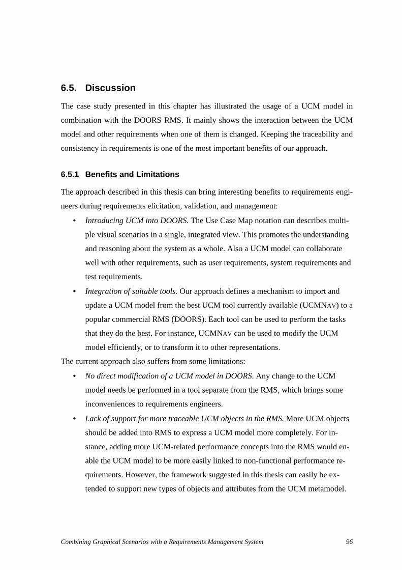
Combining Graphical Scenarios with a Requirements Management System 96
6.5. Discussion
The case study presented in this chapter has illustrated the usage of a UCM model in
combination with the DOORS RMS. It mainly shows the interaction between the UCM
model and other requirements when one of them is changed. Keeping the traceability and
consistency in requirements is one of the most important benefits of our approach.
6.5.1 Benefits and Limitations
The approach described in this thesis can bring interesting benefits to requirements engi-
neers during requirements elicitation, validation, and management:
• Introducing UCM into DOORS. The Use Case Map notation can describes multi-
ple visual scenarios in a single, integrated view. This promotes the understanding
and reasoning about the system as a whole. Also a UCM model can collaborate
well with other requirements, such as user requirements, system requirements and
test requirements.
• Integration of suitable tools. Our approach defines a mechanism to import and
update a UCM model from the best UCM tool currently available (UCMNAV) to a
popular commercial RMS (DOORS). Each tool can be used to perform the tasks
that they do the best. For instance, UCMNAV can be used to modify the UCM
model efficiently, or to transform it to other representations.
The current approach also suffers from some limitations:
• No direct modification of a UCM model in DOORS. Any change to the UCM
model needs be performed in a tool separate from the RMS, which brings some
inconveniences to requirements engineers.
• Lack of support for more traceable UCM objects in the RMS. More UCM objects
should be added into RMS to express a UCM model more completely. For in-
stance, adding more UCM-related performance concepts into the RMS would en-
able the UCM model to be more easily linked to non-functional performance re-
quirements. However, the framework suggested in this thesis can easily be ex-
tended to support new types of objects and attributes from the UCM metamodel.

Combining Graphical Scenarios with a Requirements Management System 97
6.5.2 Comparison with Other Tools
Scenario Plus Scenario Plus is a plug-in for DOORS which was introduced in section 2.3.1. It enables
requirement managers to create a wide variety of visual models within DOORS:
• Use Case Diagrams
• Goal Models
• Domain Knowledge Models
• Entity Relationship Models
• DOORS-style Information Model Diagrams
• Graham-style Agent Interaction Models
• Yourdon-style Dataflow Diagrams
• Kilov-style Object Relationship Diagrams
• Decision Trees
• i* Strategic Dependency Diagrams (for NFRs)
• Toulmin-style Argumentation Models
• Onion Models of Stakeholder Relationships
This tool provides some advantages to the requirements manager in RMS. For instance,
the above models and diagrams can be modified through the Scenario Plus plug-in in
DOORS, without relying on external tools. Also, the elements used in these diagrams are
traceable objects, which can be linked to/from other requirements. In this tool however,
these diagrams and models cannot be exported to and imported from other tools, which
would be more efficient to modify them and derive more useful information (e.g. design
information) from them. The usability of the diagram editors is very limited, and the per-
formances rather slow. It also does not support expressing UCM scenarios in DOORS.
DOORS/Analyst
DOORS/Analyst is a plug-in for DOORS which was introduced in section 2.3.2. It en-
ables users to visualize requirements using the following UML 2.0 diagrams:
• Use Case Diagrams
• Sequence Diagrams
• Class Diagrams

Combining Graphical Scenarios with a Requirements Management System 98
• Flow Chart Diagrams
• State Chart Diagrams
• Architecture Diagrams
These diagrams can be modified inside the RMS through DOORS Analyst, which pro-
vides a user interface with good performance and usability. Some specific elements in
diagrams can be linked to/from other requirements. Therefore, traceability can be estab-
lished between requirements and detail parts of these diagrams, in a way similar to our
approach.
This tool can export UML diagrams inside DOORS to other professional model-
ling tools but it does not provide an import mechanism. UCMNAV can transform UCM
models to a variety of other representations (MSC, sequence diagrams, LQN, etc.), and
UCM models are meant to be importable to DOORS. Other limitations of this tool in-
clude the lack of support for UCM models for selecting which diagram elements should
be transformed into linkable objects.
Implementations
DOORS/Analyst is not implemented in DXL. It is actually adapted from the UML dia-
gram editor from Telelogic Tau G2 (without the analysis or transformation capabilities
found in Tau). DOORS/Analyst works as a separate executable program and uses the
DOORS API to embed the diagrams created in DOORS/Analyst into the DOORS data-
base. This implementation provides a professional diagram editor inside DOORS as well
as excellent performance for integrating diagrams and traceable items. However, this im-
plementation is tightly coupled and does not provide the user with flexible ways to
change it (e.g., via a user-oriented API).
Scenario Plus implements a scenario diagram editor inside DOORS in DXL. Due
to the limitation of DXL in diagram expression, the performance of the diagram editor is
very limited.
Both plug-ins provide diagram editors inside DOORS, which are more convenient
for users than our approach. However, the lack of flexibility of DOORS/Analyst and the
limited DXL performance when drawing diagrams convinced us to give up the idea of an
internal UCM editor. Instead, our approach uses a fully functional but external scenario

Combining Graphical Scenarios with a Requirements Management System 99
editor, UCMNAV, and focuses more on expressing scenarios into traceable requirements
items.
Complementary Usage It is worth mentioning that our tool can be seen as complementary to Scenario Plus and
DOORS/Analyst. They can all cohabit within DOORS, and our tool brings a UCM per-
spective that is currently missing. This can also provide an opportunity to explore and
exploit links between UCM models and other types of requirements and design models.
Additionally, by having access to the UCMNAV TOOL, information other than just UCM
scenarios (e.g., test goals, MSCs, and performance models), can be derived from the
UCM model.
6.6. Chapter Summary
Through a Supply Chain Management case study, we demonstrated that our approach is
applicable to a realistic example, and beneficial. First, UCMs give a complementary sys-
tem view, where visual scenarios are integrated, to requirements engineers and designers.
Then, the RMS manages all requirements as a whole, including UCMs, using various
links between them. The completeness of requirements can be checked by using the filter
functions provided by the RMS. The consistency of requirements is preserved by verify-
ing requirements that have suspect links. The case study also checked the correctness and
robustness of the DXL library by covering all the creation, modification, and deletion
functions on core, map, and scenario elements.

Combining Graphical Scenarios with a Requirements Management System 100
Chapter 7. Conclusions
This chapter reviews the contributions of the thesis and discusses further work arising
from several issues encountered along the way.
7.1. Contributions
This thesis presents an extensible framework used to combine scenarios and other re-
quirements in a RMS. The key issue in this framework is introducing visual scenarios
(UCMs) into a RMS (DOORS). Through the implementation of this key issue, this thesis
makes three main contributions, with a fourth one that relates to the validation of the
framework.
Contribution 1: Abstraction of a UCM metamodel from various sources.
Based on the draft ITU.T Z.152 [20] and the UCM scenario DTDs [7], the class diagram
describing the current UCM metamodel was generated semi-automatically by using re-
verse-engineering tools. This UCM metamodel, created in collaboration with Y.X. Zeng,
was valuable in conducting the improvements to UCMNAV accomplished in this thesis.
Contribution 2: Addition of a DXL export mechanism in UCMNAV
UCMNAV was extended with a new functionality to export Use Case Map models as
DXL scripts which can be understood and executed by the target RMS tool, DOORS.
Only a subset of the UCM model information is exported, which is defined and explained
with a metamodel (see Chapter 3).
Contribution 3: Development of an extensible import/update mechanism for UCM models in DOORS
A DXL library was created for DOORS, which supports the creation and update of UCM
model in DOORS using DXL scripts generated by UCMNAV (see Chapter 4 and Chapter

Combining Graphical Scenarios with a Requirements Management System 101
5). The update of UCM models in DOORS may cause interactions with other require-
ments, at a higher level (user requirements) or at a lower level (system or test require-
ments). Change analysis is provided with various filters and views when the UCM model
is updated or external requirements are changed.
Contribution 4: Illustrative experiment on the interactive and iterative evolution of UCM models and other requirements
A case study was produced to validate our framework. The framework is applied on a
Supply Chain Management system. The case study demonstrates that UCMs and other
requirements can be checked for consistency and completeness, even as they evolve over
time (Chapter 6).
7.2. Future work
Although we have made a number of significant achievements, our framework can be
further improved. Suggestions for future work include:
Introduce other relevant UCM elements into the RMS
When using UCMs for high-level design, many UCM elements other than those in our
metamodel could be imported into the RMS as traceable objects. For instance, UCM
timestamp points and response-time requirements could be important to express per-
formance requirements. The framework could easily be extended to support such ele-
ments, if they are proved to be relevant.
Export UCM related requirements from DOORS to UCMNav
In the current approach, the link from DOORS to UCMNAV is somewhat weak. Only
changes to UCM-related requirements are exported in a textual report. The export process
could be enhanced by exporting all UCM-related requirements from DOORS to
UCMNAV and saving them as properties of the corresponding UCM elements in
UCMNAV. To achieve this goal, the current requirements report mechanism needs to be
improved to include all UCM related requirements in the report. Furthermore, UCMNav
should be improved to understand these requirements properties and enable their usage

Combining Graphical Scenarios with a Requirements Management System 102
for traceability and navigation (e.g., via pop-up menus accessible from UCM elements, à
la DOORS).
Link UCM elements with other types of requirements
In our case study, UCMs act as a bridge linking user requirements, system requirements,
and tests. Obviously, UCMs could be used at a lower level of abstraction. More detailed
UCM models could be used to refine system requirements as we move towards software
requirements, component-based system requirements, and detail design specification. We
believe that the framework is generic enough to support such application, but this remains
to be verified.
Integration with other tools, especially DOORS plug-ins
As discussed in section 6.5.2, our tool could be used in collaboration with complementary
DOORS plug-in such as DOORS/Analyst and Scenario Plus. The feasibility and useful-
ness of such combination deserves further exploration.

References 103
References
[1] Alexander, I.: Scenario Plus - Tools for Requirements Engineering. http://www.scenarioplus.org.uk. Accessed March 2004.
[2] Amyot, D.: Introduction to the User Requirements Notation: Learning by Example. In: Computer Networks, 42(3), 285-301, 21 June 2003.
[3] Amyot, D. and Andrade, R.: Description of Wireless Intelligent Network Services with Use Case Maps. In: SBRC’99, 17th Simpósio Brasileiro de Redes de Compu-tadores, Salvador, Brazil, May 1999, 418–433.
[4] Amyot, D. and Eberlein, A.: An Evaluation of Scenario Notations and Construction Approaches for Telecommunication Systems Development. In: Telecommunica-tions Systems Journal, 24:1, September 2003, 61-94.
[5] Amyot, D., Echihabi, A., He, Y.: UCMEXPORTER: Supporting Scenario Transfor-mations from Use Case Maps. In: NOuvelles TEchnnologies de la RÉpartition (NOTERE’04), Saïdia, Morocco, June 2004, 390-405. http://ucmexporter.sourceforge.net
[6] Amyot, D. and Mussbacher, G.: Bridging the Requirements/Design Gap in Dy-namic Systems with Use Case Maps (UCMs). Tutorial in: 23rd International Con-ference on Software Engineering (ICSE'01), Toronto, Canada, May 2001. http://www.UseCaseMaps.org/pub/icse01.pdf
[7] Amyot, D., He, X., He, Y. and Cho, D.Y.: Generating Scenarios from Use Case Map Specifications. In: Third International Conference on Quality Software (QSIC'03), Dallas, November 2003, 108-115.
[8] Amyot, D. and Logrippo, L.: Use Case Maps and LOTOS for the Prototyping and Validation of a Mobile Group Call System. In: Computer Communication, 23(12), 2000, 1135-1157.
[9] Amyot, D., Roy, J.-F., and Weiss. M.: UCM-Driven Testing of Web Applications. In: A. Prinz, R. Reed, and J. Reed (Eds.) 12th SDL Forum (SDL 2005), Grimstad, Norway, June 2005. LNCS 3530, Springer, 247-264.
[10] Andrade, R.: Applying Use Case Maps and Formal Methods to the Development of Wireless Mobile ATM Networks. In: Lfm2000: The Fifth NASA Langley Formal Methods Workshop, Williamsburg, Virginia, USA, June 2000.
[11] Breitman K. and Leite J.C.S.P.: Scenario Evolution: A Closer View on Rela-tion-ships. In: Proc. of the Fourth Intl Conf. on Requirements Engineering (ICRE 2000), Schaumburg, USA, 2000, 95-105.
[12] Buhr, R.J.A. and R. S. Casselman: Use Case Maps for Object-Oriented systems. Pretice-Hall, 1996.

References 104
[13] Buhr, R.J.A.: Use Case Maps as Architectural Entities for Complex Systems. In: IEEE Trans. on Software Engineering, Vol. 24, No. 12, Dec. 1998, 1131-1155.
[14] Elammari, M. and Lalonde, W.: An Agent-Oriented Methodology: High-Level and Intermediate Models. In: Proc. of the 1st Int. Workshop. on Agent-Oriented Infor-mation Systems (AOIS’99), Heidelberg, Germany, June 1999.
[15] Ghostscript, Ghostview and GSview. http://www.cs.wisc.edu/~ghost/. Accessed May 2005.
[16] Hamou-Lhadj, A., Braun, E., Amyot, D., and Lethbridge, T.: Recovering Behav-ioral Design Models from Execution Traces. 9th European Conference on Software Maintenance and Reengineering (CSMR), Manchester, UK, March 2005. IEEE Computer Society, 112-121.
[17] He, Y., Amyot, D., and Williams, A.: Synthesizing SDL from Use Case Maps: An Experiment. In: 11th SDL Forum (SDL'03), Stuttgart, Germany, July 2003. LNCS 2708, 117-136.
[18] IBM, Rational Rose Enterprise Edition 2003, http://www-306.ibm.com/software/awdtools/developer/rose/. Accessed April 2005.
[19] ITU-T: Recommendation Z.150, User Requirements Notation (URN) – Language Requirements and Framework. Geneva, Switzerland, 2003.
[20] ITU-T, URN Focus Group: Draft Rec. Z.152 – UCM: Use Case Map Notation (UCM). Geneva, Switzerland, Sept. 2003. http://www.UseCaseMaps.org/urn/
[21] Jarke M., Bui X.T., and Carroll J.M.: Scenario Management: An Interdisciplinary Approach. In: Requirements Engineering, 3(3/4), 1998, 155-173.
[22] Lamsweerde A.v.: Requirements Engineering in the Year 00: A Research Per-spective. In: Proc. of 22nd Intl Conference on Software Engineering (ICSE). Limerick, Ireland, ACM press, 2000, 5-19.
[23] Layered Queueing Resource Page. http://www.layeredqueues.org/. Accessed May 2004.
[24] Miga, A.: Application of Use Case Maps to System Design with Tool Support. M.Eng. thesis, Dept. of Systems and Computer Engineering, Carleton University, Ottawa. October 1998. http://www.UseCaseMaps.org/tools/ucmnav/
[25] Nuseibeh B. and Easterbrook S.: Requirements Engineering: A Roadmap. In: A. Finkelstein (Ed), The Future of Software Engineering, ICSE 2000, ACM Press, 2000, 35-46.
[26] Object Management Group, UML 2.0 Superstructure Specification, OMG Adopted Specification, April 30, 2004.
[27] Petriu, D.B.: Layered Software Performance Models Constructed from Use Case Map Specifications. M.Eng. thesis, Dept. of Systems and Computer Engineering, Carleton University, Ottawa, Canada, May 2001.

References 105
[28] Petriu, D.B., Amyot, D., and Woodside, M.: Scenario-Based Performance Engi-neering with UCMNAV. In: 11th SDL Forum (SDL'03), Stuttgart, Germany, July 2003. LNCS 2708, 18-35.
[29] Petriu, D.B., Amyot, D., Woodside, M, and Jiang, B.: Traceability and Evaluation in Scenario Analysis by Use Case Maps. To appear in: S. Leue and T. Systä (Eds.) Scenarios: Models, Algorithms and Tools, LNCS 3466, Springer, 2005.
[30] SpeedDev Inc., From Requirements Gathering to Product Release, http://www.speedev.com/requirements-management.htm, accessed May 2005.
[31] Telelogic AB, DOORS/Analyst, http://www.telelogic.com/products/doorsers/. Ac-cessed May 2004.
[32] Telelogic AB, DOORS/ERS, http://www.telelogic.com/products/doorsers/. Ac-cessed May 2004.
[33] Telelogic AB: DXL Reference Manual of DOORS 7.0, 2004.
[34] UCM User Group: Use Case Maps Navigator 2 (UCMNAV), http://www.usecasemaps.org/tools/ucmnav/index.shtml. Accessed April 2005.
[35] UCM User Group: UCMNAV XML DTD, version 0.23, November 2001 http://www.usecasemaps.org/xml/dtdindex.html.
[36] WS-I – Web Services Interoperability Organization: Supply Chain Management: Use Case Model, Version 1.0, 2003. http://www.ws-i.org
[37] WS-I – Web Services Interoperability Organization: Supply Chain Management: Sample Application Architecture, Version 1.0.1, 2003. http://www.ws-i.org
[38] Weiss, M. and Amyot, D.: Designing and Evolving Business Models with URN. Montreal Conference on eTechnologies (MCeTech), Montréal, Canada, January 2005, 149-162.
[39] Weiss, M. and Amyot, D.: Business Process Modeling with URN. In: International Journal of E-Business Research, 1(3), 63-90, July-September 2005.
[40] Yi, Z.: CNAP Specification and Validation: A Design Methodology Using LOTOS and UCM. M.C.S. thesis, SITE, University of Ottawa, Canada, 2000.
[41] Zeng, Y.X.: Transforming Use Case Maps to the Core Scenario Model Representa-tion. M.C.S. thesis, SITE, University of Ottawa, Canada, 2005.

Appendix A: System Requirements of SCM 106
Appendix A: System Requirements of SCM
Retailer System
Functional requirements for Purchase Goods:
The retailer system should provide the ability for the consumer to navigate the Web site.
The retailer system should presents its catalogue to the consumer
The retailer system should provide the ability for the consumer to input the order informa-tion
The retailer system should receive an order from the consumer that contains a list of items
The retailer system should generate the list of items shipped.
The retailer system should validate the order by checking that the requested products exist.
Functional requirements for Source Goods:
The retailer system should present list of requested items to the first warehouse
The retailer system should present remaining list of requested items to the next warehouse.
The retailer system should present records the items shipped.
The retailer system should provide the ability for the warehouse to get the next item re-quested in the list of goods.
The retailer system should provide the ability for the warehouse to decrements the stocks by the requested quantity.
The retailer system should provide the ability for the warehouse to ship the requested items to the consumer.
The retailer system should provide the ability for the warehouse to test whether there are more items requested.
The retailer system should allow the second warehouse to have sufficient stocks if desired.
Functional requirements for Replenish Stock:
The warehouse should be able to build the order for a manufacturer.
The warehouse should be able to select the appropriate manufacturer.
The warehouse should be able to place the order to the selected manufacturer.
The warehouse should be able to receive the products shipped by the manufacturer.
The warehouse should be able to update its stock upon the receipts of goods.
The warehouse should be able to send acknowledgement back to the manufacturer after receiving goods.
The warehouse should be able to determine whether the replenishment has timed out.

Appendix A: System Requirements of SCM 107
Manufacturing System
Functional requirements for Supply Finished Goods:
The manufacturer should be able to reject an order either due to a malformed order or a request for an invalid quantity.
The manufacturer should be able to ship goods to the warehouse.
The manufacturer should be able to validate an order received from a warehouse.
The manufacturer should be able to send acknowledgement to a warehouse.
The manufacturer should check the inventory for the requested product.
The manufacturer should ship the products for the order from the warehouse.
The manufacturer should update its inventory after shipping products.
Functional requirements for Manufacture Finished Goods:
The manufacturer should have the ability to determine the parts (and their quantities) re-quired to produce the finished product.
The manufacturer should have the ability to produce the requested product.
The manufacturer should have the ability to stack finished goods in (manufacturer's) warehouse.

Appendix B: Sample API Function in DXL 108
Appendix B: Sample API Function in DXL
The following function is meant to illustrate the details of one function of the DOORS
API for UCM import, in order to give an idea of the complexity of this API. The respon-
sibility function (discussed in section 4.2.1) is used to create or update one responsibility
object in the responsibility module. Responsibility attributes are specified by parameters.
“ responsibilityID” is a key attribute whose value is unique. In the beginning of the func-
tion, we try to open a responsibility module in edit mode. If this fails, an error message is
displayed. If this is successful, the function scans all responsibilities in this module to
find out the responsibility specified by the key “ responsibilityID” . If the responsibility
exists in the module, all its attributes are verified according to the values passed through
the parameters of this function. Any new value of the responsibility’s attributes will be
updated. Notice that its pre-treated attribute “Deleted” is restored to false. If the specified
responsibility is not found in the module, then it is created with the attributes specified by
the function parameters in the invocation.
bool r esponsi bi l i t y ( st r i ng r esponsi bi l i t y I D, s t r i ng r esponsi bi l i t yName, s t r i ng t heDescr i pt i on, s t r i ng pr ocessor Demand) { Obj ect cur r ent Obj ect bool hasFound s t r i ng t empSt r i ng Modul e r espModul e=edi t ( " Responsi bi l i t y Modul e" , f al se) i f ( ! ( nul l r espModul e) ) { hasFound=f al se f or cur r ent Obj ect i n r espModul e do{ t empSt r i ng=cur r ent Obj ect . " I D" i f ( t empSt r i ng==r esponsi bi l i t y I D) { hasFound=t r ue t empSt r i ng=cur r ent Obj ect . " NameOf Responsi bi l i t y" i f ( t empSt r i ng! =r esponsi bi l i t yName) { cur r ent Obj ect . " NameOf Responsi bi l i t y" =r esponsi bi l i t yName cur r ent Obj ect . " Obj ect Headi ng" =r esponsi bi l i t yName } t empSt r i ng=cur r ent Obj ect . " Pr ocessor Demand"
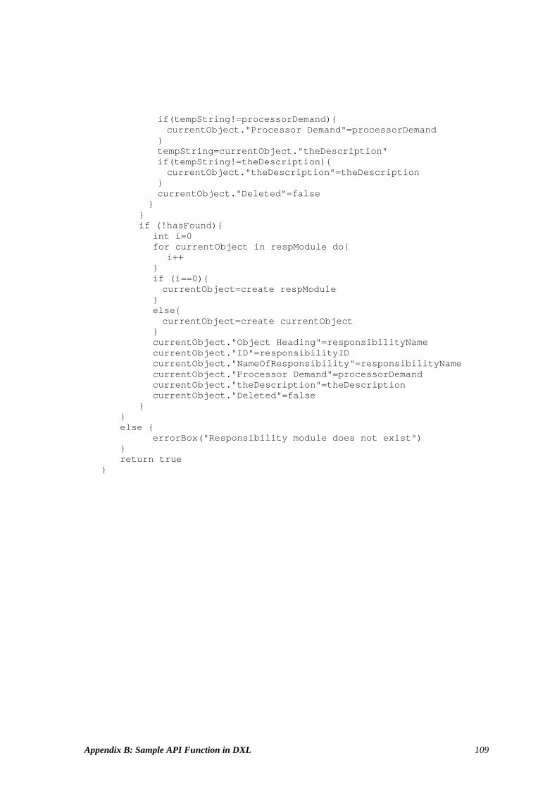
Appendix B: Sample API Function in DXL 109
i f ( t empSt r i ng! =pr ocessor Demand) { cur r ent Obj ect . " Pr ocessor Demand" =pr ocessor Demand } t empSt r i ng=cur r ent Obj ect . " t heDescr i pt i on" i f ( t empSt r i ng! =t heDescr i pt i on) { cur r ent Obj ect . " t heDescr i pt i on" =t heDescr i pt i on } cur r ent Obj ect . " Del et ed" =f al se } } i f ( ! hasFound) { i nt i =0 f or cur r ent Obj ect i n r espModul e do{ i ++ } i f ( i ==0) { cur r ent Obj ect =cr eat e r espModul e } el se{ cur r ent Obj ect =cr eat e cur r ent Obj ect } cur r ent Obj ect . " Obj ect Headi ng" =r esponsi bi l i t yName cur r ent Obj ect . " I D" =r esponsi bi l i t y I D cur r ent Obj ect . " NameOf Responsi bi l i t y" =r esponsi bi l i t yName cur r ent Obj ect . " Pr ocessor Demand" =pr ocessor Demand cur r ent Obj ect . " t heDescr i pt i on" =t heDescr i pt i on cur r ent Obj ect . " Del et ed" =f al se } } el se { er r or Box( " Responsi bi l i t y modul e does not exi st " ) } r et ur n t r ue }

Appendix C: UCM Model for the Supply Chain Management 110
Appendix C: UCM Model for the Supply Chain Management
This is the first version of the UCM model used in the case study. The model content,
generated as a UCMNAV report, is presented in the following pages.