Combinations for Variable speed drives customer assembly ...schneidermccb.com/pdf-cat/Industry...
12
2 1 3 4 5 6 7 8 9 10 2 1 3 4 5 6 7 8 9 10 60708-EN.indd version: 1.0 2 Applications Circuit-breaker/contactor/drive combinations can be used to ensure continuous service of the installation with optimum safety. The type of circuit-breaker/contactor coordination selected can reduce maintenance costs in the event of a motor short-circuit by minimizing the time required to make the necessary repairs and the cost of replacement equipment. The suggested combinations provide type 1 or type 2 coordination depending on the drive rating. Type 2 coordination: A motor short-circuit will not damage the device or affect its settings. The motor starter must be able to operate once the electrical fault has been removed. The electrical isolation provided by the circuit- breaker will not be affected by the short-circuit. Welding of the contactor contacts is permissible if they can be separated easily. Type 1 coordination: The electrical isolation provided by the circuit-breaker will not be affected by the incident and no other elements apart from the contactor are damaged as a result of the motor short-circuit. The drive controls the motor, provides protection against short-circuits between the drive and the motor and protects the motor cable against overloads. The overload protection is provided by the drive's motor thermal protection. If this protection is removed, external thermal protection must be provided. Before restarting the installation, the cause of the trip must be removed. Motor starters for IP 20 drives Motor Drive Circuit-breaker Line contactor Power (1) Reference Reference (2) Rating Irm Reference (3) (4) kW HP A A Single-phase supply voltage: 200…240 V 50/60 Hz. Type 2 coordination 0.37 0.5 ATV 61H075M3 GV2 L14 10 – LC1 D09pp 0.75 1 ATV 61HU15M3 GV2 L16 14 – LC1 D18pp 1.5 2 ATV 61HU22M3 GV2 L20 18 – LC1 D25pp 2.2 3 ATV 61HU30M3 GV2 L32 32 – LC1 D32pp 3 – ATV 61HU40M3 (5) GV2 L32 32 – LC1 D32pp 4 5 ATV 61HU55M3 (5) GV3 L40 40 – LC1 D40App 5.5 7.5 ATV 61HU75M3 (5) GV3 L50 50 – LC1 D50App Single-phase supply voltage: 200…240 V 50/60 Hz. Type 1 coordination 0.37 0.5 ATV 61H075M3 GV2 L14 10 – LC1 D09pp 0.75 1 ATV 61HU15M3 GV2 L16 14 – LC1 D09pp 1.5 2 ATV 61HU22M3 GV2 L20 18 – LC1 D09pp 2.2 3 ATV 61HU30M3 GV2 L32 32 – LC1 D18pp 3 – ATV 61HU40M3 (5) GV2 L32 32 – LC1 D18pp 4 5 ATV 61HU55M3 (5) GV3 L40 40 300 LC1 D32pp 5.5 7.5 ATV 61HU75M3 (5) GV3 L50 50 300 LC1 D38pp (1) Standard power ratings for 230 V 50/60 Hz 4-pole motors The HP values given are NEC-compliant (National Electrical Code). (2) Breaking capacity of circuit-breakers according to standard IEC 60947-2: Circuit-breaker Icu (kA) for 240 V GV2 L14, GV2 L16 130 GV2 L20, GV2 L32 GV3 L40, GV3 L50 50 (3) Composition of contactors: LC1 D09 to LC1 D50A: 3 poles + 1 "N/O" auxiliary contact and 1 "N/C" auxiliary contact. (4) Replace pp with the control circuit voltage reference indicated in the table below. Volts a 24 48 110 220 230 240 LC1 Dpp 50 Hz B5 E5 F5 M5 P5 U5 60 Hz B6 E6 F6 M6 – U6 50/60 Hz B7 E7 F7 M7 P7 U7 For other voltages available between 24 V and 660 V, or a DC control circuit, please contact our Customer Care Centre. (5) A line choke must be added (see page 60705/8). + + Combinations for customer assembly Variable speed drives Altivar 61 Motor starters: supply voltage 200…240 V GV2 L20 + LC1 D25pp + ATV 61HU22M3 PF107483SE DF526153 DF526131
-
Upload
phungkhanh -
Category
Documents
-
view
225 -
download
2
Transcript of Combinations for Variable speed drives customer assembly ...schneidermccb.com/pdf-cat/Industry...

2
1
3
4
5
6
7
8
9
10
2
1
3
4
5
6
7
8
9
10
60708-EN.indd version: 1.0 22
ApplicationsCircuit-breaker/contactor/drive combinations can be used to ensure continuous service of the installation with optimum safety.The type of circuit-breaker/contactor coordination selected can reduce maintenance costs in the event of a motor short-circuit by minimizing the time required to make the necessary repairs and the cost of replacement equipment. The suggested combinations provide type 1 or type 2 coordination depending on the drive rating.
Type 2 coordination: A motor short-circuit will not damage the device or affect its settings. The motor starter must be able to operate once the electrical fault has been removed. The electrical isolation provided by the circuit-breaker will not be affected by the short-circuit. Welding of the contactor contacts is permissible if they can be separated easily.
Type 1 coordination: The electrical isolation provided by the circuit-breaker will not be affected by the incident and no other elements apart from the contactor are damaged as a result of the motor short-circuit.
The drive controls the motor, provides protection against short-circuits between the drive and the motor and protects the motor cable against overloads. The overload protection is provided by the drive's motor thermal protection. If this protection is removed, external thermal protection must be provided.Before restarting the installation, the cause of the trip must be removed.Motor starters for IP 20 drives Motor Drive Circuit-breaker Line contactor Power(1)
Reference Reference (2)
Rating Irm Reference (3) (4)
kW HP A ASingle-phase supply voltage: 200…240 V 50/60 Hz. Type 2 coordination
0.37 0.5 ATV 61H075M3 GV2 L14 10 – LC1 D09pp
0.75 1 ATV 61HU15M3 GV2 L16 14 – LC1 D18pp
1.5 2 ATV 61HU22M3 GV2 L20 18 – LC1 D25pp
2.2 3 ATV 61HU30M3 GV2 L32 32 – LC1 D32pp
3 – ATV 61HU40M3 (5)
GV2 L32 32 – LC1 D32pp
4 5 ATV 61HU55M3 (5)
GV3 L40 40 – LC1 D40App
5.5 7.5 ATV 61HU75M3 (5)
GV3 L50 50 – LC1 D50App
Single-phase supply voltage: 200…240 V 50/60 Hz. Type 1 coordination0.37 0.5 ATV 61H075M3 GV2 L14 10 – LC1 D09pp
0.75 1 ATV 61HU15M3 GV2 L16 14 – LC1 D09pp
1.5 2 ATV 61HU22M3 GV2 L20 18 – LC1 D09pp
2.2 3 ATV 61HU30M3 GV2 L32 32 – LC1 D18pp
3 – ATV 61HU40M3 (5)
GV2 L32 32 – LC1 D18pp
4 5 ATV 61HU55M3 (5)
GV3 L40 40 300 LC1 D32pp
5.5 7.5 ATV 61HU75M3 (5)
GV3 L50 50 300 LC1 D38pp
(1) Standard power ratings for 230 V 50/60 Hz 4-pole motorsThe HP values given are NEC-compliant (National Electrical Code).
(2) Breaking capacity of circuit-breakers according to standard IEC 60947-2:Circuit-breaker Icu (kA) for 240 V
GV2 L14, GV2 L16 130
GV2 L20, GV2 L32 GV3 L40, GV3 L50
50
(3) Composition of contactors:LC1 D09 to LC1 D50A: 3 poles + 1 "N/O" auxiliary contact and 1 "N/C" auxiliary contact.
(4) Replace pp with the control circuit voltage reference indicated in the table below.Volts a 24 48 110 220 230 240
LC1 Dpp 50 Hz B5 E5 F5 M5 P5 U560 Hz B6 E6 F6 M6 – U650/60 Hz B7 E7 F7 M7 P7 U7
For other voltages available between 24 V and 660 V, or a DC control circuit, please contact our Customer Care Centre.(5) A line choke must be added (see page 60705/8).
+
+
Combinations for customer assembly
Variable speed drivesAltivar 61Motor starters: supply voltage 200…240 V
GV2 L20+LC1 D25pp+ATV 61HU22M3
PF1
0748
3SE
DF5
2615
3D
F526
131

2
1
3
4
5
6
7
8
9
10
2
1
3
4
5
6
7
8
9
10
60708-EN.indd version: 1.0 33
Combinations for customer assembly (continued)
Variable speed drivesAltivar 61Motor starters: supply voltage 200…240 V
Motor starters for IP 20 drives Motor Drive Circuit-breaker Line contactor Power (1) Reference Reference
(2) Rating Irm Reference
(3) (4)kW HP A AThree-phase supply voltage: 200…240 V 50/60 Hz. Type 2 coordination
0.75 1 ATV 61H075M3 GV2 L10 6.3 – LC1 D09pp
1.5 2 ATV 61HU15M3 GV2 L16 14 – LC1 D18pp
2.2 3 ATV 61HU22M3 GV2 L20 18 – LC1 D18pp
3 – ATV 61HU30M3 GV2 L22 25 – LC1 D25pp
4 5 ATV 61HU40M3 GV2 L32 32 – LC1 D25pp
5.5 7.5 ATV 61HU55M3 GV3 L40 40 – LC1 D40App
7.5 10 ATV 61HU75M3 GV3 L50 50 – LC1 D50App
11 15 ATV 61HD11M3X GV3 L65 65 – LC1 D65App
15 20 ATV 61HD15M3X NS80HMA80 80 480 LC1 D80pp
18.5 25 ATV 61HD18M3X NS80HMA80 80 480 LC1 D80pp
22 30 ATV 61HD22M3X NSX100pMA100 100 600 LC1 D95pp
30 40 ATV 61HD30M3X NSX160pMA150 150 1350 LC1 D150pp
37 50 ATV 61HD37M3X NSX160pMA150 150 1350 LC1 D150pp
45 60 ATV 61HD45M3X NSX250pMA220 220 1980 LC1 F185pp
55 75 ATV 61HD55M3X NSX250pMA220 220 1980 LC1 F225pp
75 100 ATV 61HD75M3X NSX400p Micrologic 1.3M 320 1920 LC1 F265pp
90 125 ATV 61HD90M3X NSX630p Micrologic 1.3M 500 3000 LC1 F330pp
Three-phase supply voltage: 200…240 V 50/60 Hz. Type 1 coordination0.75 1 ATV 61H075M3 GV2 L10 6.3 – LC1 D09pp
1.5 2 ATV 61HU15M3 GV2 L16 14 – LC1 D09pp
2.2 3 ATV 61HU22M3 GV2 L20 18 – LC1 D09pp
3 – ATV 61HU30M3 GV2 L22 25 – LC1 D18pp
4 5 ATV 61HU40M3 GV2 L32 32 – LC1 D18pp
5.5 7.5 ATV 61HU55M3 GV3 L40 40 – LC1 D25pp
7.5 10 ATV 61HU75M3 GV3 L50 50 – LC1 D32pp
11 15 ATV 61HD11M3X GV3 L65 65 – LC1 D40App
15 20 ATV 61HD15M3X NS80HMA80 80 480 LC1 D50App
18.5 25 ATV 61HD18M3X NS80HMA80 80 480 LC1 D50App
22 30 ATV 61HD22M3X NSX100pMA100 100 600 LC1 D80pp
30 40 ATV 61HD30M3X NSX160pMA150 150 1350 LC1 D95pp
37 50 ATV 61HD37M3X NSX160pMA150 150 1350 LC1 D115pp
45 60 ATV 61HD45M3X NSX250pMA220 220 1980 LC1 D115pp
55 75 ATV 61HD55M3X NSX250pMA220 220 1980 LC1 D115pp
75 100 ATV 61HD75M3X NSX400p Micrologic 1.3M 320 1920 LC1 F185pp
90 125 ATV 61HD90M3X NSX630p Micrologic 1.3M 500 3000 LC1 F265pp
(1) Standard power ratings for 230 V 50/60 Hz 4-pole motorsThe HP values given are NEC-compliant (National Electrical Code).
(2) For references to be completed, replace the dot with the letter corresponding to the circuit-breaker breaking performance (B, F, N, H, S or L).Breaking capacity of circuit-breakers according to standard IEC 60947-2:
Circuit-breaker Icu (kA) for 240 VB F N H S L
GV2 L10 130 – – – – – –GV2 L16…L32 GV3 L40…L65
50 – – – – – –
NS80HMA 100 – – – – – –NSX100pMA…NSX250pMA – 40 85 90 100 120 150NSX400p, NSX630p – – 40 85 100 120 150(3) Composition of contactors:
LC1 D09 to LC1 D150: 3 poles + 1 "N/O" auxiliary contact and 1 "N/C" auxiliary contact.LC1 F185 to LC1 F330: 3 poles. To add auxiliary contacts or other accessories, please refer to the "Motor-starter solutions - Control and protection components" catalogue.
(4) Replace pp with the control circuit voltage reference indicated in the table below.Volts a 24 48 110 220 230 240
LC1 D09…D150 50 Hz B5 E5 F5 M5 P5 U560 Hz B6 E6 F6 M6 – U650/60 Hz B7 E7 F7 M7 P7 U7
LC1 F185, F225 50 Hz (LX1 coil) B5 E5 F5 M5 P5 U560 Hz (LX1 coil) – E6 F6 M6 – U640…400 Hz (LX9 coil) – E7 F7 M7 P7 U7
LC1 F265, LC1 F330 40…400 Hz (LX1 coil) B7 E7 F7 M7 P7 U7For other voltages available between 24 V and 660 V, or a DC control circuit, please contact our Customer Care Centre.
+
+
DF5
2613
1D
F526
156
PF1
0748
3SE
GV3 L40+LC1 D40App+ATV 61HU55M3
2
1
3
4
5
6
7
8
9
10
2
1
3
4
5
6
7
8
9
10
60708-EN.indd version: 1.0 44
Motor starters for IP 20 drives Motor Drive Circuit-breaker Line contactorPower (1) Reference Reference (2) Rating Irm Reference (4) (5)kW HP A AThree-phase supply voltage: 380…415 V 50/60 Hz. Type 2 coordination
0.75 1 ATV 61H075N4 GV2 L08 4 – LC1 D09pp
1.5 2 ATV 61HU15N4 GV2 L10 6.3 – LC1 D09pp
2.2 3 ATV 61HU22N4 GV2 L14 10 – LC1 D25pp
3 – ATV 61HU30N4 GV2 L16 14 – LC1 D25pp
4 5 ATV 61HU40N4 GV2 L16 14 – LC1 D25pp
5.5 7.5 ATV 61HU55N4 GV2 L22 25 – LC1 D25pp
7.5 10 ATV 61HU75N4 GV3 L32 32 – LC1 D40App
11 15 ATV 61HD11N4 GV3 L40 40 – LC1 D50App
15 20 ATV 61HD15N4 GV3 L50 50 – LC1 D65App
18.5 25 ATV 61HD18N4 GV3 L50 50 – LC1 D65App
22 30 ATV 61HD22N4 GV3 L65 65 – LC1 D65App
30 40 ATV 61HD30N4 NS80HMA80 80 480 LC1 D80pp
37 50 ATV 61HD37N4 NSX100pMA100 100 600 LC1 D95pp
45 60 ATV 61HD45N4 NSX160pMA150 150 1350 LC1 D115pp
55 75 ATV 61HD55N4 NSX160pMA150 150 1350 LC1 D150pp
75 100 ATV 61HD75N4 NSX250pMA220 220 1980 LC1 F185pp
90 125 ATV 61HD90N4 NSX250pMA220 220 1980 LC1 F185pp
110 150 ATV 61HC11N4 NSX250pMA220 220 1980 LC1 F225pp
132 200 ATV 61HC13N4 NSX400p Micrologic 1.3M 320 1920 LC1 F265pp
160 250 ATV 61HC16N4 NSX400p Micrologic 1.3M 320 1920 LC1 F330pp
200 300 ATV 61HC22N4 NSX630p Micrologic 1.3M 500 3000 LC1 F400pp
220 350 ATV 61HC22N4 NSX630p Micrologic 1.3M 500 3000 LC1 F400pp
250 400 ATV 61HC25N4 NSX630p Micrologic 1.3M 500 3000 LC1 F500pp
280 450 ATV 61HC31N4 NSX630p Micrologic 1.3M 500 3000 LC1 F500pp
315 500 ATV 61HC31N4 NS800L Micrologic 2 or 5 (LR OFF) 800 1600 LC1 F630pp
355 – ATV 61HC40N4 NS800L Micrologic 2 or 5 (LR OFF) 800 1600 LC1 F630pp
400 600 ATV 61HC40N4 NS800L Micrologic 2 or 5 (LR OFF) 800 1600 LC1 F800pp
500 700 ATV 61HC50N4 NS1000L Micrologic 2 or 5 (LR OFF) 1000 2000 LC1 BLpp
560 800 ATV 61HC63N4 NS1000L Micrologic 2 or 5 (LR OFF) 1000 2000 LC1 BMpp
(1) Standard power ratings for 400 V 50/60 Hz 4-pole motorsThe HP values given are NEC-compliant (National Electrical Code).
(2) For references to be completed, replace the dot with the letter corresponding to the circuit-breaker breaking performance (B, F, N, H, S or L).Breaking capacity of circuit-breakers according to standard IEC 60947-2:
Circuit-breaker Icu (kA) for 400 VB F N H S L
GV2 L08…L16 (3) 130 – – – – – –GV2 L16 (3), GV2 L22GV3 L32…L65
50 – – – – – –
NS80HMA 70 – – – – – –NSX100pMA…NSX250pMA – 25 36 50 70 100 150NSX400p, NSX630p – – 36 50 70 100 150NS800L Micrologic 2 or 5NS1000L Micrologic 2 or 5
– – – – – – 150
(3) GV2 L16: Icu of 130 when combined with an ATV 61HU30N4, Icu of 50 when combined with an ATV 61HU40N4.(4) Composition of contactors:
LC1 D09 to LC1 D150: 3 poles + 1 "N/O" auxiliary contact and 1 "N/C" auxiliary contact.LC1 Fppp, LC1 BL and LC1 BM: 3 poles. To add auxiliary contacts or other accessories, please refer to the "Motor-starter solutions - Control and protection components" catalogue.
(5) Replace pp with the control circuit voltage reference indicated in the table below.Volts a 24 48 110 220 230 240
LC1 D09…D150 50 Hz B5 E5 F5 M5 P5 U560 Hz B6 E6 F6 M6 – U650/60 Hz B7 E7 F7 M7 P7 U7
LC1 F185, F225 50 Hz (LX1 coil) B5 E5 F5 M5 P5 U560 Hz (LX1 coil) – E6 F6 M6 – U640…400 Hz (LX9 coil) – E7 F7 M7 P7 U7
LC1 F265, F330 40…400 Hz (LX1 coil) B7 E7 F7 M7 P7 U7LC1 F400…F800 40…400 Hz (LX1 coil) – E7 F7 M7 P7 U7LC1 BL, LC1 BM 50…400 Hz (WB1 coil) – – F M P UFor other voltages available between 24 V and 660 V, or a DC control circuit, please contact our Customer Care Centre.
Combinations for customer assembly (continued)
Variable speed drivesAltivar 61Motor starters: supply voltage 380…415 V
NSX160pMA150+LC1 D115pp+ATV 61HD45N4
PF1
0758
3SE
+
+
DP
F526
158
PF0
9531
6

2
1
3
4
5
6
7
8
9
10
2
1
3
4
5
6
7
8
9
10
60708-EN.indd version: 1.0 55
Motor starters for IP 20 drives Motor Drive Circuit-breaker Line contactorPower (1) Reference Reference (2) Rating Irm Reference (3) (4)kW HP A AThree-phase supply voltage: 380…415 V 50/60 Hz. Type 1 coordination
0.75 1 ATV 61H075N4 GV2 L08 4 – LC1 D09pp
1.5 2 ATV 61HU15N4 GV2 L10 6.3 – LC1 D09pp
2.2 3 ATV 61HU22N4 GV2 L14 10 – LC1 D09pp
3 – ATV 61HU30N4 GV2 L16 14 – LC1 D09pp
4 5 ATV 61HU40N4 GV2 L16 14 – LC1 D18pp
5.5 7.5 ATV 61HU55N4 GV2 L22 25 – LC1 D25pp
7.5 10 ATV 61HU75N4 GV3 L32 32 – LC1 D40App
11 15 ATV 61HD11N4 GV3 L40 40 – LC1 D40App
15 20 ATV 61HD15N4 GV3 L50 50 – LC1 D50App
18.5 25 ATV 61HD18N4 GV3 L50 50 – LC1 D50App
22 30 ATV 61HD22N4 GV3 L65 65 – LC1 D65App
30 40 ATV 61HD30N4 NS80HMA80 80 480 LC1 D65App
37 50 ATV 61HD37N4 NSX100pMA100 100 600 LC1 D95pp
45 60 ATV 61HD45N4 NSX160pMA150 150 1350 LC1 D115pp
55 75 ATV 61HD55N4 NSX160pMA150 150 1350 LC1 D115pp
75 100 ATV 61HD75N4 NSX250pMA220 220 1980 LC1 F185pp
90 125 ATV 61HD90N4 NSX250pMA220 220 1980 LC1 F185pp
110 150 ATV 61HC11N4 NSX250pMA220 220 1980 LC1 F225pp
132 200 ATV 61HC13N4 NSX400p Micrologic 1.3M 320 1920 LC1 F265pp
160 250 ATV 61HC16N4 NSX400p Micrologic 1.3M 320 1920 LC1 F330pp
200 300 ATV 61HC22N4 NSX630p Micrologic 1.3M 500 3000 LC1 F400pp
220 350 ATV 61HC22N4 NSX630p Micrologic 1.3M 500 3000 LC1 F400pp
250 400 ATV 61HC25N4 NSX630p Micrologic 1.3M 500 3000 LC1 F500pp
280 450 ATV 61HC31N4 NSX630p Micrologic 1.3M 500 3000 LC1 F500pp
315 500 ATV 61HC31N4 NS800L Micrologic 2 or 5 (LR OFF) 800 1600 LC1 F630pp
355 – ATV 61HC40N4 NS800L Micrologic 2 or 5 (LR OFF) 800 1600 LC1 F630pp
400 600 ATV 61HC40N4 NS800L Micrologic 2 or 5 (LR OFF) 800 1600 LC1 F630pp
500 700 ATV 61HC50N4 NS1000L Micrologic 2 or 5 (LR OFF) 1000 2000 LC1 F630pp
560 800 ATV 61HC63N4 NS1000L Micrologic 2 or 5 (LR OFF) 1000 2000 LC1 F630pp
630 900 ATV 61HC63N4 NS1250 Micrologic 2 or 5 (LR OFF) 1000 2000 LC1 F630pp
(1) Standard power ratings for 400 V 50/60 Hz 4-pole motorsThe HP values given are NEC-compliant (National Electrical Code).
(2) For references to be completed, replace the dot with the letter corresponding to the circuit-breaker breaking performance (B, F, N, H, S or L).Breaking capacity of circuit-breakers according to standard IEC 60947-2:
Circuit-breaker Icu (kA) for 400 VB F N H S L
GV2 L08…L14 130 – – – – – –GV2 L16, GV2 L22GV3 L32…L65
50 – – – – – –
NS80HMA 70 – – – – – –NSX100pMA…NSX250pMA – 25 36 50 65 100 150NSX400p, NSX630p – – 36 50 65 100 150NS800L Micrologic 2 or 5NS1000L Micrologic 2 or 5
– – – – – – 150
NS1250 Micrologic 2 or 5 – – – 50 65 – –(3) Composition of contactors:
LC1 D09 to LC1 D115: 3 poles + 1 "N/O" auxiliary contact and 1 "N/C" auxiliary contact.LC1 F185 to F630: 3 poles. To add auxiliary contacts or other accessories, please refer to the "Motor-starter solutions - Control and protection components" catalogue.
(4) Replace pp with the control circuit voltage reference indicated in the table below.Volts a 24 48 110 220 230 240
LC1 D09…D115 50 Hz B5 E5 F5 M5 P5 U560 Hz B6 E6 F6 M6 – U650/60 Hz B7 E7 F7 M7 P7 U7
LC1 F185, F225 50 Hz (LX1 coil) B5 E5 F5 M5 P5 U560 Hz (LX1 coil) – E6 F6 M6 – U640…400 Hz (LX9 coil) – E7 F7 M7 P7 U7
LC1 F265, F330 40…400 Hz (LX1 coil) B7 E7 F7 M7 P7 U7LC1 F400…F630 40…400 Hz (LX1 coil) – E7 F7 M7 P7 U7For other voltages available between 24 V and 660 V, or a DC control circuit, please contact our Customer Care Centre.
Combinations forcustomer assembly (continued)
Variable speed drivesAltivar 61Motor starters: supply voltage 380…415 V
+
+
PF5
1075
81S
E
NSX100pMA100+LC1 D95pp+ATV 61HD37N4
DF5
2615
7P
F509
5316

2
1
3
4
5
6
7
8
9
10
2
1
3
4
5
6
7
8
9
10
60708-EN.indd version: 1.0 66
Motor starters for IP 54 drives Motor Drive Circuit-breaker Line contactorPower (1) Reference Reference (2) Rating Irm Reference (3) (4)kW HP A AThree-phase supply voltage: 380…415 V 50/60 Hz. Type 2 coordination
0.75 1 ATV 61W075N4ATV 61W075N4C
GV2 L07 2.5 – LC1 D09pp
1.5 2 ATV 61WU15N4ATV 61WU15N4C
GV2 L08 4 – LC1 D09pp
2.2 3 ATV 61WU22N4ATV 61WU22N4C
GV2 L10 6.3 – LC1 D09pp
3 – ATV 61WU30N4ATV 61WU30N4C
GV2 L14 10 – LC1 D25pp
4 5 ATV 61WU40N4ATV 61WU40N4C
GV2 L14 10 – LC1 D25pp
5.5 7.5 ATV 61WU55N4ATV 61WU55N4C
GV2 L16 14 – LC1 D25pp
7.5 10 ATV 61WU75N4ATV 61WU75N4C
GV3 L32 32 – LC1 D40App
11 15 ATV 61WD11N4ATV 61WD11N4C
GV3 L40 40 – LC1 D40App
15 20 ATV 61WD15N4ATV 61WD15N4C
GV3 L50 50 – LC1 D50App
18.5 25 ATV 61WD18N4ATV 61WD18N4C
GV3 L50 50 – LC1 D50App
22 30 ATV 61WD22N4ATV 61WD22N4C
GV3 L65 65 – LC1 D65App
30 40 ATV 61WD30N4ATV 61WD30N4C
NS80HMA80 80 480 LC1 D80pp
37 50 ATV 61WD37N4ATV 61WD37N4C
NS80HMA80 80 480 LC1 D80pp
45 60 ATV 61WD45N4ATV 61WD45N4C
NSX100pMA100 100 600 LC1 D95pp
55 75 ATV 61WD55N4ATV 61WD55N4C
NSX160pMA150 150 1350 LC1 D115pp
75 100 ATV 61WD75N4ATV 61WD75N4C
NSX160pMA150 150 1350 LC1 D150pp
90 125 ATV 61WD90N4ATV 61WD90N4C
NSX250pMA220 220 1980 LC1 F185pp
(1) Standard power ratings for 400 V 50/60 Hz 4-pole motorsThe HP values given are NEC-compliant (National Electrical Code).
(2) For references to be completed, replace the dot with the letter corresponding to the circuit-breaker breaking performance (B, F, N, H, S or L).Breaking capacity of circuit-breakers according to standard IEC 60947-2:
Circuit-breaker Icu (kA) for 400 VB F N H S L
GV2 L07…L14 130 – – – – – –GV2 L16GV3 L32…L65
50 – – – – – –
NS80HMA 70 – – – – – –NSX100pMA …250pMA – 25 36 50 70 100 150(3) Composition of contactors:
LC1 D09 to LC1 D150: 3 poles + 1 "N/O" auxiliary contact and 1 "N/C" auxiliary contact.LC1 F185: 3 poles. To add auxiliary contacts or other accessories, please refer to the "Motor-starter solutions - Control and protection components" catalogue.
(4) Replace pp with the control circuit voltage reference given in the table below:Volts a 24 48 110 220 230 240
LC1 D09…D150 50 Hz B5 E5 F5 M5 P5 U560 Hz B6 E6 F6 M6 – U650/60 Hz B7 E7 F7 M7 P7 U7
LC1 F185 50 Hz (LX1 coil) B5 E5 F5 M5 P5 U560 Hz (LX1 coil) – E6 F6 M6 – U640…400 Hz (LX9 coil) – E7 F7 M7 P7 U7
For other voltages available between 24 V and 660 V, or a DC control circuit, please contact our Customer Care Centre.
Combinations forcustomer assembly (continued)
Variable speed drivesAltivar 61Motor starters: supply voltage 380…415 V
DP
F526
158
PF0
9531
7
+
+
PF1
0749
2SE
NSX160pMA150+LC1 D115pp+ATV 61WD55N4

2
1
3
4
5
6
7
8
9
10
2
1
3
4
5
6
7
8
9
10
60708-EN.indd version: 1.0 77
Motor starters for IP 54 drives Motor Drive Circuit-breaker Line contactorPower (1) Reference Reference (2) Rating Irm Reference (3) (4)kW HP A AThree-phase supply voltage: 380…415 V 50/60 Hz. Type 1 coordination
0.75 1 ATV 61W075N4ATV 61W075N4C
GV2 L07 2.5 – LC1 D09pp
1.5 2 ATV 61WU15N4ATV 61WU15N4C
GV2 L08 4 – LC1 D09pp
2.2 3 ATV 61WU22N4ATV 61WU22N4C
GV2 L10 6.3 – LC1 D09pp
3 – ATV 61WU30N4ATV 61WU30N4C
GV2 L14 10 – LC1 D09pp
4 5 ATV 61WU40N4ATV 61WU40N4C
GV2 L14 10 – LC1 D18pp
5.5 7.5 ATV 61WU55N4ATV 61WU55N4C
GV2 L16 14 – LC1 D18pp
7.5 10 ATV 61WU75N4ATV 61WU75N4C
GV3 L32 32 – LC1 D25pp
11 15 ATV 61WD11N4ATV 61WD11N4C
GV3 L40 40 – LC1 D40App
15 20 ATV 61WD15N4ATV 61WD15N4C
GV3 L50 40 – LC1 D50App
18.5 25 ATV 61WD18N4ATV 61WD18N4C
GV3 L50 50 – LC1 D50App
22 30 ATV 61WD22N4ATV 61WD22N4C
GV3 L65 65 – LC1 D65App
30 40 ATV 61WD30N4ATV 61WD30N4C
NS80HMA80 80 480 LC1 D65App
37 50 ATV 61WD37N4ATV 61WD37N4C
NS80HMA80 80 480 LC1 D80pp
45 60 ATV 61WD45N4ATV 61WD45N4C
NSX100pMA100 100 600 LC1 D80pp
55 75 ATV 61WD55N4ATV 61WD55N4C
NSX160pMA150 150 1350 LC1 D115pp
75 100 ATV 61WD75N4ATV 61WD75N4C
NSX160pMA150 150 1350 LC1 D150pp
90 125 ATV 61WD90N4ATV 61WD90N4C
NSX250pMA220 220 1980 LC1 F185pp
(1) Standard power ratings for 400 V 50/60 Hz 4-pole motorsThe HP values given are NEC-compliant (National Electrical Code).
(2) For references to be completed, replace the dot with the letter corresponding to the circuit-breaker breaking performance (B, F, N, H, S or L).Breaking capacity of circuit-breakers according to standard IEC 60947-2:
Circuit-breaker Icu (kA) for 400 VB F N H S L
GV2 L07…L14 130 – – – – – –GV2 L16GV3 L32…L65
50 – – – – – –
NS80HMA 70 – – – – – –NSX100pMA…NSX250pMA – 25 36 50 70 100 150(3) Composition of contactors:
LC1 D09 to LC1 D150: 3 poles + 1 "N/O" auxiliary contact and 1 "N/C" auxiliary contact.LC1 F185: 3 poles. To add auxiliary contacts or other accessories, please refer to the "Motor-starter solutions - Control and protection components" catalogue.Replace pp with the control circuit voltage reference indicated in the table below.
Volts a 24 48 110 220 230 240LC1 D09…D150 50 Hz B5 E5 F5 M5 P5 U5
60 Hz B6 E6 F6 M6 – U650/60 Hz B7 E7 F7 M7 P7 U7
LC1 F185 50 Hz (LX1 coil) B5 E5 F5 M5 P5 U560 Hz (LX1 coil) – E6 F6 M6 – U640…400 Hz (LX9 coil) – E7 F7 M7 P7 U7
For other voltages available between 24 V and 660 V, or a DC control circuit, please contact our Customer Care Centre.
Combinations forcustomer assembly (continued)
Variable speed drivesAltivar 61Motor starters: supply voltage 380…415 V
+
+
DF5
2613
1D
F526
150
PF1
0749
5SE
GV2 L07+LC1 D09pp+ATV 61W075N4
2
1
3
4
5
6
7
8
9
10
2
1
3
4
5
6
7
8
9
10
60708-EN.indd version: 1.0 88
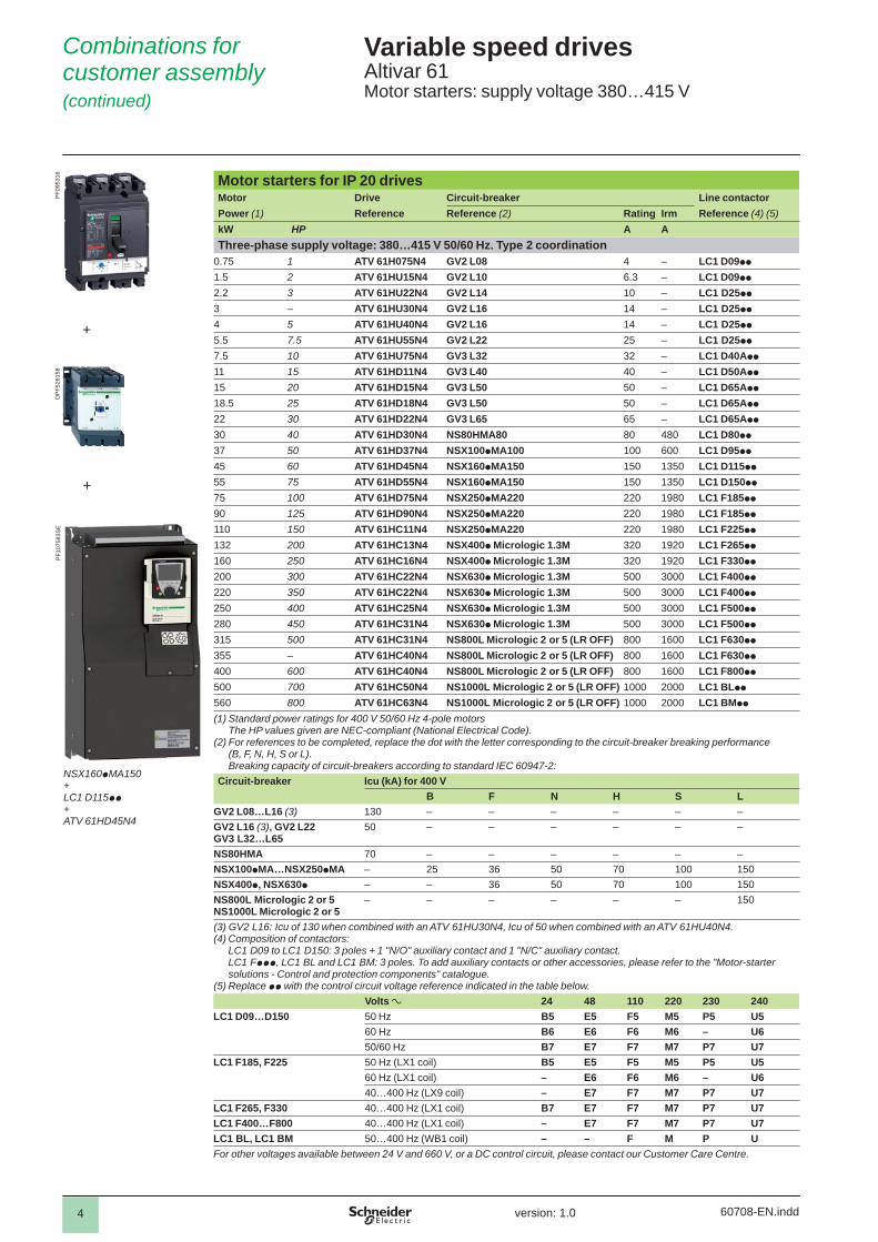
Motor starters for IP 20 drives Motor Drive Circuit-breaker Line contactorPower (1) Reference Reference (2) Rating Irm Reference (4) (5)kW HP A AThree-phase supply voltage: 440…480 V 50/60 Hz. Type 2 coordination
0.75 1 ATV 61H075N4 GV2 L08 4 – LC1 D25pp
1.5 2 ATV 61HU15N4 GV2 L10 6.3 – LC1 D25pp
2.2 3 ATV 61HU22N4 GV2 L14 10 – LC1 D25pp
3 – ATV 61HU30N4 GV2 L14 10 – LC1 D25pp
4 5 ATV 61HU40N4 GV2 L16 14 – LC1 D25pp
5.5 7.5 ATV 61HU55N4 GV2 L20 18 – LC1 D25pp
7.5 10 ATV 61HU75N4 GV3 L25 25 – LC1 D32pp
11 15 ATV 61HD11N4 GV3 L32 32 – LC1 D40App
15 20 ATV 61HD15N4 GV3 L50 50 – LC1 D50App
18.5 25 ATV 61HD18N4 GV3 L50 50 – LC1 D50App
22 30 ATV 61HD22N4 GV3 L50 50 – LC1 D65App
30 40 ATV 61HD30N4 GV3 L65 65 – LC1 D65App
37 50 ATV 61HD37N4 NS80HMA80 80 480 LC1 D80pp
45 60 ATV 61HD45N4 NSX100pMA100 100 600 LC1 D115pp
55 75 ATV 61HD55N4 NSX160pMA150 150 1350 LC1 D115pp
75 100 ATV 61HD75N4 NSX250pMA220 220 1980 LC1 F185pp
90 125 ATV 61HD90N4 NSX250pMA220 220 1980 LC1 F185pp
110 150 ATV 61HC11N4 NSX250pMA220 220 1980 LC1 F185pp
132 200 ATV 61HC13N4 NSX250pMA220 220 1980 LC1 F265pp
160 250 ATV 61HC16N4 NSX400p Micrologic 1.3M 320 1920 LC1 F265pp
200 300 ATV 61HC22N4 NSX630p Micrologic 1.3M 500 3000 LC1 F400pp
220 350 ATV 61HC22N4 NSX630p Micrologic 1.3M 500 3000 LC1 F400pp
250 400 ATV 61HC25N4 NSX630p Micrologic 1.3M 500 3000 LC1 F500pp
280 450 ATV 61HC31N4 NSX630p Micrologic 1.3M 500 3000 LC1 F500pp
315 500 ATV 61HC31N4 NS800L Micrologic 2 or 5 (LR OFF) 800 1600 LC1 F630pp
355 – ATV 61HC40N4 NS800L Micrologic 2 or 5 (LR OFF) 800 1600 LC1 F630pp
400 600 ATV 61HC40N4 NS800L Micrologic 2 or 5 (LR OFF) 800 1600 LC1 F780pp
500 700 ATV 61HC50N4 NS1000L Micrologic 2 or 5 (LR OFF) 1000 2000 LC1 F780pp
560 800 ATV 61HC63N4 NS1000L Micrologic 2 or 5 (LR OFF) 1000 2000 LC1 F780pp
630 900 ATV 61HC63N4 NS1000L Micrologic 2 or 5 (LR OFF) 1000 2000 LC1 F780pp
(1) Standard power ratings for 400 V 50/60 Hz 4-pole motorsThe HP values given are NEC-compliant (National Electrical Code).
(2) For references to be completed, replace the dot with the letter corresponding to the circuit-breaker breaking performance (B, F, N, H, S or L).Breaking capacity of circuit-breakers according to standard IEC 60947-2:
Circuit-breaker Icu (kA) for 440 V
B F N H S LGV2 L08…GV2 L14 (3) 130 – – – – – –GV2 L14 (3)…L20 20 – – – – – –GV3 L25…L65 50 – – – – – –NS80HMA 65 – – – – – –NSX100pMA…NSX250pMA – 20 35 50 65 90 130NSX400pMA…NSX630pMA – – 30 42 65 90 130NS800L Micrologic 2 or 5NS1000L Micrologic 2 or 5
– – – – – – 130
(3) GV2 L14: Icu of 130 when combined with an ATV 61HU22N4, Icu of 20 when combined with an ATV 61HU30N4. (4) Composition of contactors:
LC1 D25 to LC1 D115: 3 poles + 1 "N/O" auxiliary contact and 1 "N/C" auxiliary contact.LC1 F185 to LC1 F780: 3 poles. To add auxiliary contacts or other accessories, please refer to the "Motor-starter solutions - Control and protection components" catalogue.
(5) Replace pp with the control circuit voltage reference given in the table below:Volts a 24 48 110 220 230 240
LC1 D25…D115 50 Hz B5 E5 F5 M5 P5 U560 Hz B6 E6 F6 M6 – U650/60 Hz B7 E7 F7 M7 P7 U7
LC1 F185 50 Hz (LX1 coil) B5 E5 F5 M5 P5 U560 Hz (LX1 coil) – E6 F6 M6 – U640…400 Hz (LX9 coil) – E7 F7 M7 P7 U7
LC1 F265 40…400 Hz (LX1 coil) B7 E7 F7 M7 P7 U7LC1 F400…F630 40…400 Hz (LX1 coil) – E7 F7 M7 P7 U7LC1 F780 40…400 Hz (LX1 coil) – – F7 M7 P7 U7For other voltages available between 24 V and 660 V, or a DC control circuit, please contact our Customer Care Centre.
Combinations forcustomer assembly (continued)
Variable speed drivesAltivar 61Motor starters: supply voltage 440…480 V
NSX100pMA150+LC1 D115pp+ATV 61HD45N4
PF1
0758
3SE
+
DP
F526
158
PF0
9531
6
+

2
1
3
4
5
6
7
8
9
10
2
1
3
4
5
6
7
8
9
10
60708-EN.indd version: 1.0 99
Motor starters for IP 20 drives Motor Drive Circuit-breaker Line contactorPower (1) Reference Reference (2) Rating Irm Reference (4) (5)kW HP A AThree-phase supply voltage: 440…480 V 50/60 Hz. Type 1 coordination
0.75 1 ATV 61H075N4 GV2 L08 4 – LC1 D09pp
1.5 2 ATV 61HU15N4 GV2 L10 6.3 – LC1 D09pp
2.2 3 ATV 61HU22N4 GV2 L14 10 – LC1 D09pp
3 – ATV 61HU30N4 GV2 L14 10 – LC1 D09pp
4 5 ATV 61HU40N4 GV2 L16 14 – LC1 D09pp
5.5 7.5 ATV 61HU55N4 GV2 L20 18 – LC1 D09pp
7.5 10 ATV 61HU75N4 GV3 L25 25 – LC1 D25pp
11 15 ATV 61HD11N4 GV3 L32 32 – LC1 D32pp
15 20 ATV 61HD15N4 GV3 L50 50 – LC1 D40App
18.5 25 ATV 61HD18N4 GV3 L50 50 – LC1 D40App
22 30 ATV 61HD22N4 GV3 L50 50 – LC1 D50App
30 40 ATV 61HD30N4 GV3 L65 65 – LC1 D65App
37 50 ATV 61HD37N4 NS80HMA80 80 480 LC1 D80pp
45 60 ATV 61HD45N4 NSX100pMA100 100 600 LC1 D95pp
55 75 ATV 61HD55N4 NSX160pMA150 150 1350 LC1 D115pp
75 100 ATV 61HD75N4 NSX250pMA220 220 1980 LC1 D115pp
90 125 ATV 61HD90N4 NSX250pMA220 220 1980 LC1 D150pp
110 150 ATV 61HC11N4 NSX250pMA220 220 1980 LC1 D150pp
132 200 ATV 61HC13N4 NSX250pMA220 220 1980 LC1 F225pp
160 250 ATV 61HC16N4 NSX400p Micrologic 1.3M 320 1920 LC1 F225pp
200 300 ATV 61HC22N4 NSX630p Micrologic 1.3M 500 3000 LC1 F330pp
220 350 ATV 61HC22N4 NSX630p Micrologic 1.3M 500 3000 LC1 F330pp
250 400 ATV 61HC25N4 NSX630p Micrologic 1.3M 500 3000 LC1 F400pp
280 450 ATV 61HC31N4 NSX630p Micrologic 1.3M 500 3000 LC1 F500pp
315 500 ATV 61HC31N4 NS800L Micrologic 2 or 5 (LR OFF) 800 1600 LC1 F500pp
355 – ATV 61HC40N4 NS800L Micrologic 2 or 5 (LR OFF) 800 1600 LC1 F630pp
400 600 ATV 61HC40N4 NS800L Micrologic 2 or 5 (LR OFF) 800 1600 LC1 F630pp
500 700 ATV 61HC50N4 NS1000L Micrologic 2 or 5 (LR OFF) 800 1600 LC1 F630pp
560 800 ATV 61HC63N4 NS1000L Micrologic 2 or 5 (LR OFF) 1000 2000 LC1 F630pp
630 900 ATV 61HC63N4 NS1000L Micrologic 2 or 5 (LR OFF) 1000 2000 LC1 F630pp
(1) Standard power ratings for 400 V 50/60 Hz 4-pole motorsThe HP values given are NEC-compliant (National Electrical Code).
(2) For references to be completed, replace the dot with the letter corresponding to the circuit-breaker breaking performance (B, F, N, H, S or L).Breaking capacity of circuit-breakers according to standard IEC 60947-2:
Circuit-breaker Icu (kA) for 440 VB F N H S L
GV2 L08…L14 (3) 130 – – – – – –GV2 L14 (3)…L20 20 – – – – – –GV3 L25…L65 50 – – – – – –NS80HMA 65 – – – – – –NSX100pMA…NSX250pMA – 20 35 50 65 90 130NSX400p, NSX630p – – 30 42 65 90 130NS800L Micrologic 2 or 5 NS1000L Micrologic 2 or 5
– – – – – – 130
(3) GV2 L14: Icu of 130 when combined with an ATV 61HU22N4, Icu of 20 when combined with an ATV 61HU30N4. (4) Composition of contactors:
LC1 D09 to LC1 D150: 3 poles + 1 "N/O" auxiliary contact and 1 "N/C" auxiliary contact.LC1 F225 to LC1 F630: 3 poles. To add auxiliary contacts or other accessories, please refer to the "Motor-starter solutions - Control and protection components" catalogue.
(5) Replace pp with the control circuit voltage reference given in the table below:Volts a 24 48 110 220 230 240
LC1 D09…D150 50 Hz B5 E5 F5 M5 P5 U560 Hz B6 E6 F6 M6 – U650/60 Hz B7 E7 F7 M7 P7 U7
LC1 F265, LC1 F330 40…400 Hz (LX1 coil) B7 E7 F7 M7 P7 U7LC1 F400…F630 40…400 Hz (LX1 coil) – E7 F7 M7 P7 U7For other voltages available between 24 V and 660 V, or a DC control circuit, please contact our Customer Care Centre.
Combinations forcustomer assembly (continued)
Variable speed drivesAltivar 61Motor starters: supply voltage 440…480 V
NSX160pMA150+LC1 D115pp+ATV 61HD55N4
PF1
0758
3SE
+
+
DP
F526
158
PF0
9531
6
2
1
3
4
5
6
7
8
9
10
2
1
3
4
5
6
7
8
9
10
60708-EN.indd version: 1.0 1010
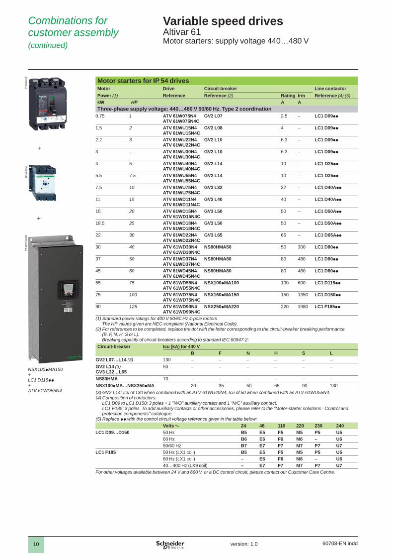
Motor starters for IP 54 drives Motor Drive Circuit-breaker Line contactorPower (1) Reference Reference (2) Rating Irm Reference (4) (5)kW HP A AThree-phase supply voltage: 440…480 V 50/60 Hz. Type 2 coordination
0.75 1 ATV 61W075N4ATV 61W075N4C
GV2 L07 2.5 – LC1 D09pp
1.5 2 ATV 61WU15N4ATV 61WU15N4C
GV2 L08 4 – LC1 D09pp
2.2 3 ATV 61WU22N4ATV 61WU22N4C
GV2 L10 6.3 – LC1 D09pp
3 – ATV 61WU30N4ATV 61WU30N4C
GV2 L10 6.3 – LC1 D09pp
4 5 ATV 61WU40N4ATV 61WU40N4C
GV2 L14 10 – LC1 D25pp
5.5 7.5 ATV 61WU55N4ATV 61WU55N4C
GV2 L14 10 – LC1 D25pp
7.5 10 ATV 61WU75N4ATV 61WU75N4C
GV3 L32 32 – LC1 D40App
11 15 ATV 61WD11N4ATV 61WD11N4C
GV3 L40 40 – LC1 D40App
15 20 ATV 61WD15N4ATV 61WD15N4C
GV3 L50 50 – LC1 D50App
18.5 25 ATV 61WD18N4ATV 61WD18N4C
GV3 L50 50 – LC1 D50App
22 30 ATV 61WD22N4ATV 61WD22N4C
GV3 L65 65 – LC1 D65App
30 40 ATV 61WD30N4ATV 61WD30N4C
NS80HMA50 50 300 LC1 D80pp
37 50 ATV 61WD37N4ATV 61WD37N4C
NS80HMA80 80 480 LC1 D80pp
45 60 ATV 61WD45N4ATV 61WD45N4C
NS80HMA80 80 480 LC1 D80pp
55 75 ATV 61WD55N4ATV 61WD55N4C
NSX100pMA100 100 600 LC1 D115pp
75 100 ATV 61WD75N4ATV 61WD75N4C
NSX160pMA150 150 1350 LC1 D150pp
90 125 ATV 61WD90N4ATV 61WD90N4C
NSX250pMA220 220 1980 LC1 F185pp
(1) Standard power ratings for 400 V 50/60 Hz 4-pole motorsThe HP values given are NEC-compliant (National Electrical Code).
(2) For references to be completed, replace the dot with the letter corresponding to the circuit-breaker breaking performance (B, F, N, H, S or L).Breaking capacity of circuit-breakers according to standard IEC 60947-2:
Circuit-breaker Icu (kA) for 440 VB F N H S L
GV2 L07…L14 (3) 130 – – – – – –GV2 L14 (3)GV3 L32…L65
50 – – – – – –
NS80HMA 70 – – – – – –NSX100pMA…NSX250pMA – 20 35 50 65 90 130(3) GV2 L14: Icu of 130 when combined with an ATV 61WU40N4, Icu of 50 when combined with an ATV 61WU55N4. (4) Composition of contactors:
LC1 D09 to LC1 D150: 3 poles + 1 "N/O" auxiliary contact and 1 "N/C" auxiliary contact.LC1 F185: 3 poles. To add auxiliary contacts or other accessories, please refer to the "Motor-starter solutions - Control and protection components" catalogue.
(5) Replace pp with the control circuit voltage reference given in the table below:Volts a 24 48 110 220 230 240
LC1 D09…D150 50 Hz B5 E5 F5 M5 P5 U560 Hz B6 E6 F6 M6 – U650/60 Hz B7 E7 F7 M7 P7 U7
LC1 F185 50 Hz (LX1 coil) B5 E5 F5 M5 P5 U560 Hz (LX1 coil) – E6 F6 M6 – U640…400 Hz (LX9 coil) – E7 F7 M7 P7 U7
For other voltages available between 24 V and 660 V, or a DC control circuit, please contact our Customer Care Centre.
Combinations forcustomer assembly (continued)
Variable speed drivesAltivar 61Motor starters: supply voltage 440…480 V
+
+
DF5
2615
8P
F095
316
PF1
0749
2SE
NSX100pMA150+LC1 D115pp+ATV 61WD55N4
2
1
3
4
5
6
7
8
9
10
2
1
3
4
5
6
7
8
9
10
60708-EN.indd version: 1.0 1111
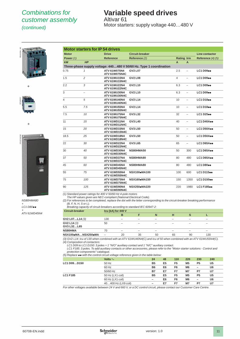
Motor starters for IP 54 drives Motor Drive Circuit-breaker Line contactorPower (1) Reference Reference (2) Rating Irm Reference (4) (5)kW HP A AThree-phase supply voltage: 440…480 V 50/60 Hz. Type 1 coordination
0.75 1 ATV 61W075N4ATV 61W075N4C
GV2 L07 2.5 – LC1 D09pp
1.5 2 ATV 61WU15N4ATV 61WU15N4C
GV2 L08 4 – LC1 D09pp
2.2 3 ATV 61WU22N4ATV 61WU22N4C
GV2 L10 6.3 – LC1 D09pp
3 – ATV 61WU30N4ATV 61WU30N4C
GV2 L10 6.3 – LC1 D09pp
4 5 ATV 61WU40N4ATV 61WU40N4C
GV2 L14 10 – LC1 D18pp
5.5 7.5 ATV 61WU55N4ATV 61WU55N4C
GV2 L14 10 – LC1 D18pp
7.5 10 ATV 61WU75N4ATV 61WU75N4C
GV3 L32 32 – LC1 D25pp
11 15 ATV 61WD11N4ATV 61WD11N4C
GV3 L40 40 – LC1 D40App
15 20 ATV 61WD15N4ATV 61WD15N4C
GV3 L50 50 – LC1 D50App
18.5 25 ATV 61WD18N4ATV 61WD18N4C
GV3 L50 50 – LC1 D50App
22 30 ATV 61WD22N4ATV 61WD22N4C
GV3 L65 65 – LC1 D65App
30 40 ATV 61WD30N4ATV 61WD30N4C
NS80HMA50 50 300 LC1 D65App
37 50 ATV 61WD37N4ATV 61WD37N4C
NS80HMA80 80 480 LC1 D65App
45 60 ATV 61WD45N4ATV 61WD45N4C
NS80HMA80 80 480 LC1 D80pp
55 75 ATV 61WD55N4ATV 61WD55N4C
NSX100pMA100 100 600 LC1 D115pp
75 100 ATV 61WD75N4ATV 61WD75N4C
NSX160pMA150 150 1350 LC1 D150pp
90 125 ATV 61WD90N4ATV 61WD90N4C
NSX250pMA220 220 1980 LC1 F185pp
(1) Standard power ratings for 400 V 50/60 Hz 4-pole motorsThe HP values given are NEC-compliant (National Electrical Code).
(2) For references to be completed, replace the dot with the letter corresponding to the circuit-breaker breaking performance (B, F, N, H, S or L).Breaking capacity of circuit-breakers according to standard IEC 60947-2:
Circuit-breaker Icu (kA) for 440 VB F N H S L
GV2 L07…L14 (3) 130 – – – – – –GV2 L14 (3)GV3 L32…L65
50 – – – – – –
NS80HMA 70 – – – – – –NSX100pMA…NSX250pMA – 20 35 50 65 90 130(3) GV2 L14: Icu of 130 when combined with an ATV 61WU40N4(C) and Icu of 50 when combined with an ATV 61WU55N4(C).(4) Composition of contactors:
LC1 D09 to LC1 D150: 3 poles + 1 "N/O" auxiliary contact and 1 "N/C" auxiliary contact.LC1 F185: 3 poles. To add auxiliary contacts or other accessories, please refer to the "Motor-starter solutions - Control and protection components" catalogue.
(5) Replace pp with the control circuit voltage reference given in the table below:Volts a 24 48 110 220 230 240
LC1 D09…D150 50 Hz B5 E5 F5 M5 P5 U560 Hz B6 E6 F6 M6 – U650/60 Hz B7 E7 F7 M7 P7 U7
LC1 F185 50 Hz (LX1 coil) B5 E5 F5 M5 P5 U560 Hz (LX1 coil) – E6 F6 M6 – U640…400 Hz (LX9 coil) – E7 F7 M7 P7 U7
For other voltages available between 24 V and 660 V, or a DC control circuit, please contact our Customer Care Centre.
Combinations forcustomer assembly (continued)
Variable speed drivesAltivar 61Motor starters: supply voltage 440…480 V
+
+
NS80HMA80+LC1 D80pp+ATV 61WD45N4
PF1
0749
2SE
DF5
2615
7P
B10
1591
_SE
2
1
3
4
5
6
7
8
9
10
2
1
3
4
5
6
7
8
9
10
60708-EN.indd version: 1.0 1212
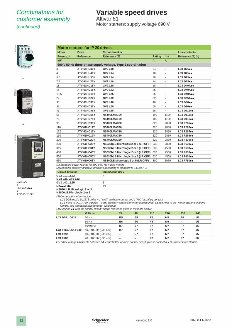
Motor starters for IP 20 drives Motor Drive Circuit-breaker Line contactorPower (1) Reference Reference (2) Rating Irm Reference (3) (4)kW A A690 V 50 Hz three-phase supply voltage. Type 2 coordination
3 ATV 61HU30Y GV2 L10 6.3 – LC1 D25pp
4 ATV 61HU40Y GV2 L14 10 – LC1 D25pp
5.5 ATV 61HU55Y GV2 L14 10 – LC1 D25pp
7.5 ATV 61HU75Y GV2 L16 14 – LC1 D25pp
11 ATV 61HD11Y GV2 L20 18 – LC1 D40App
15 ATV 61HD15Y GV2 L22 25 – LC1 D40App
18.5 ATV 61HD18Y GV3 L25 25 – LC1 D40App
22 ATV 61HD22Y GV3 L32 32 – LC1 D65App
30 ATV 61HD30Y GV3 L40 40 – LC1 D80pp
37 ATV 61HD37Y GV3 L50 50 – LC1 D80pp
45 ATV 61HD45Y GV3 L65 65 – LC1 D115pp
55 ATV 61HD55Y NS100LMA100 100 1100 LC1 D115pp
75 ATV 61HD75Y NS100LMA100 100 1100 LC1 D115pp
90 ATV 61HD90Y NS400LMA320 320 2880 LC1 F265pp
110 ATV 61HC11Y NS400LMA320 320 2880 LC1 F265pp
132 ATV 61HC13Y NS400LMA320 320 2880 LC1 F265pp
160 ATV 61HC16Y NS400LMA320 320 2880 LC1 F265pp
200 ATV 61HC20Y NS400LMA320 320 2880 LC1 F330pp
250 ATV 61HC25Y NS630bLB Micrologic 2 or 5 (LR OFF) 630 2880 LC1 F630pp
315 ATV 61HC31Y NS630bLB Micrologic 2 or 5 (LR OFF) 630 4500 LC1 F630pp
400 ATV 61HC40Y NS630bLB Micrologic 2 or 5 (LR OFF) 630 4500 LC1 F630pp
500 ATV 61HC50Y NS630bLB Micrologic 2 or 5 (LR OFF) 630 4500 LC1 F630pp
630 ATV 61HC63Y NS800LB Micrologic 2 or 5 (LR OFF) 800 5670 LC1 F780pp
(1) Standard power ratings for 690 V 50 Hz 4-pole motors(2) Breaking capacity of circuit-breakers according to standard IEC 60947-2:Circuit-breaker Icu (kA) for 690 V
GV2 L10…L22GV3 L25, GV3 L32
4
GV3 L40…L65 5NSpppLMANS630bLB Micrologic 2 or 5NS800LB Micrologic 2 or 5
75
(3) Composition of contactors:LC1 D25 to LC1 D115: 3 poles + 1 "N/O" auxiliary contact and 1 "N/C" auxiliary contact.LC1 F265 to LC1 F780: 3 poles. To add auxiliary contacts or other accessories, please refer to the "Motor-starter solutions - Control and protection components" catalogue.
(4) Replace pp with the control circuit voltage reference given in the table below:Volts a 24 48 110 220 230 240
LC1 D25…D115 50 Hz B5 E5 F5 M5 P5 U560 Hz B6 E6 F6 M6 – U650/60 Hz B7 E7 F7 M7 P7 U7
LC1 F265, LC1 F330 40…400 Hz (LX1 coil) B7 E7 F7 M7 P7 U7LC1 F630 40…400 Hz (LX1 coil) – E7 F7 M7 P7 U7LC1 F780 40…400 Hz (LX1 coil) – – F7 M7 P7 U7For other voltages available between 24 V and 660 V, or a DC control circuit, please contact our Customer Care Centre.
Combinations forcustomer assembly (continued)
Variable speed drivesAltivar 61Motor starters: supply voltage 690 V
DF5
2613
1
+
+
DF5
2615
6
GV2 L20+LC1 D40App+ATV 61HD11Y
PF1
0758
2SE
2
1
3
4
5
6
7
8
9
10
2
1
3
4
5
6
7
8
9
10
60708-EN.indd version: 1.0 1313
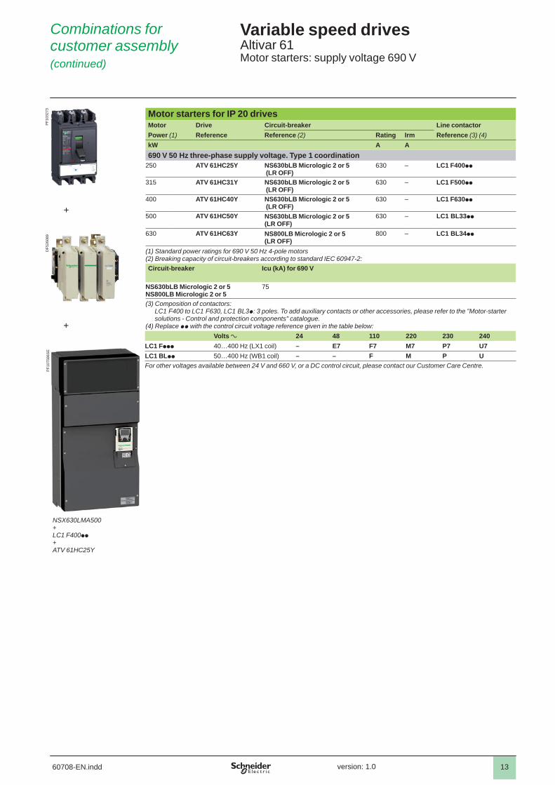
Motor starters for IP 20 drives Motor Drive Circuit-breaker Line contactorPower (1) Reference Reference (2) Rating Irm Reference (3) (4)kW A A690 V 50 Hz three-phase supply voltage. Type 1 coordination
250 ATV 61HC25Y NS630bLB Micrologic 2 or 5 (LR OFF)
630 – LC1 F400pp
315 ATV 61HC31Y NS630bLB Micrologic 2 or 5 (LR OFF)
630 – LC1 F500pp
400 ATV 61HC40Y NS630bLB Micrologic 2 or 5 (LR OFF)
630 – LC1 F630pp
500 ATV 61HC50Y NS630bLB Micrologic 2 or 5 (LR OFF)
630 – LC1 BL33pp
630 ATV 61HC63Y NS800LB Micrologic 2 or 5 (LR OFF)
800 – LC1 BL34pp
(1) Standard power ratings for 690 V 50 Hz 4-pole motors(2) Breaking capacity of circuit-breakers according to standard IEC 60947-2:Circuit-breaker Icu (kA) for 690 V
NS630bLB Micrologic 2 or 5NS800LB Micrologic 2 or 5
75
(3) Composition of contactors:LC1 F400 to LC1 F630, LC1 BL3p: 3 poles. To add auxiliary contacts or other accessories, please refer to the "Motor-starter solutions - Control and protection components" catalogue.
(4) Replace pp with the control circuit voltage reference given in the table below:Volts a 24 48 110 220 230 240
LC1 Fppp 40…400 Hz (LX1 coil) – E7 F7 M7 P7 U7LC1 BLpp 50…400 Hz (WB1 coil) – – F M P UFor other voltages available between 24 V and 660 V, or a DC control circuit, please contact our Customer Care Centre.
Combinations forcustomer assembly (continued)
Variable speed drivesAltivar 61Motor starters: supply voltage 690 V
PF1
0327
3
+
NSX630LMA500+LC1 F400pp+ATV 61HC25Y
PF1
0758
6SE
+
DF5
2608
9


![Atmel SAM D09 - rowleydownload.co.uk · 9 Atmel | SMART SAM D09 [P RELIMINARY DATASHEET] Atmel-42414A-SAM-D09-Datasheet_08/2015 6. I/O Multiplexing and Considerations 6.1 Multiplexed](https://static.fdocuments.us/doc/165x107/5f05568f7e708231d41278a5/atmel-sam-d09-9-atmel-smart-sam-d09-p-reliminary-datasheet-atmel-42414a-sam-d09-datasheet082015.jpg)