Combinational Logic Chapter 4. Content List Decoders Encoders Multiplexers.
23
Combinational Logic Chapter 4
-
Upload
jessica-kelly -
Category
Documents
-
view
236 -
download
2
Transcript of Combinational Logic Chapter 4. Content List Decoders Encoders Multiplexers.

Combinational Logic
Chapter 4

Content List
Decoders Encoders Multiplexers
4.9 Decoders
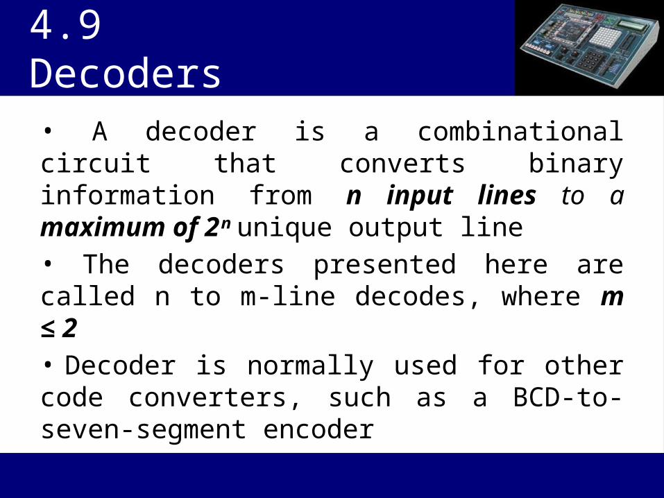
• A decoder is a combinational circuit that converts binary information from n input lines to a maximum of 2ⁿ unique output line• The decoders presented here are called n to m-line decodes, where m ≤ 2• Decoder is normally used for other code converters, such as a BCD-to-seven-segment encoder
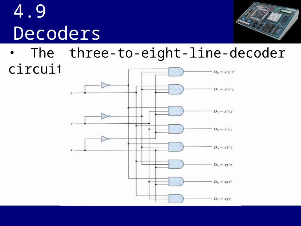
• The three-to-eight-line-decoder circuit
4.9 Decoders

4.9 Decoders

4.9 Decoders
• 2-to-4-line decoder with NAND gate
Note : it is more economical to produce inverted AND operation with NAND gates
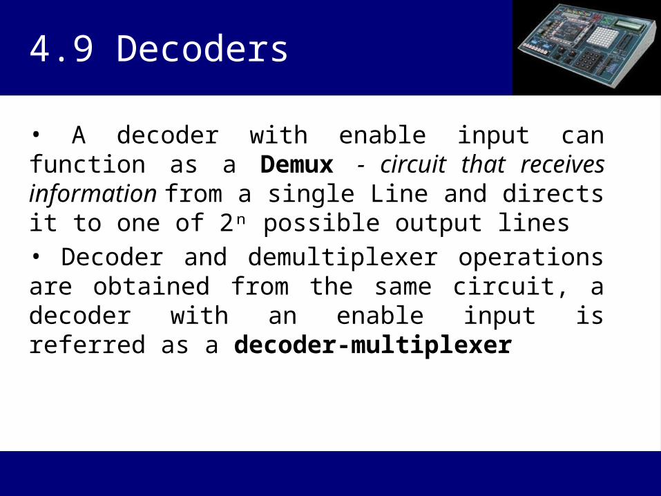
• A decoder with enable input can function as a Demux - circuit that receives information from a single Line and directs it to one of 2ⁿ possible output lines• Decoder and demultiplexer operations are obtained from the same circuit, a decoder with an enable input is referred as a decoder-multiplexer
4.9 Decoders

• Two 3-to-8-line decoders with enable inputs connected to form a 4-to-16- line decoder
4.9 Decoders
How many 3-to-8 line decoders require to make 5-to-32 line decoder ?
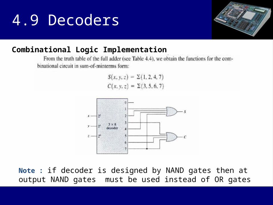
Combinational Logic Implementation
4.9 Decoders
Note : if decoder is designed by NAND gates then at output NAND gates must be used instead of OR gates

4.10 Encoders
• An encoder is a digital circuit that performs the inverse operation of a decoder• An encoder has 2ⁿ (or fewer) input lines and n output lines• The output lines, as an aggregate, generate the binary code corresponding to the input value
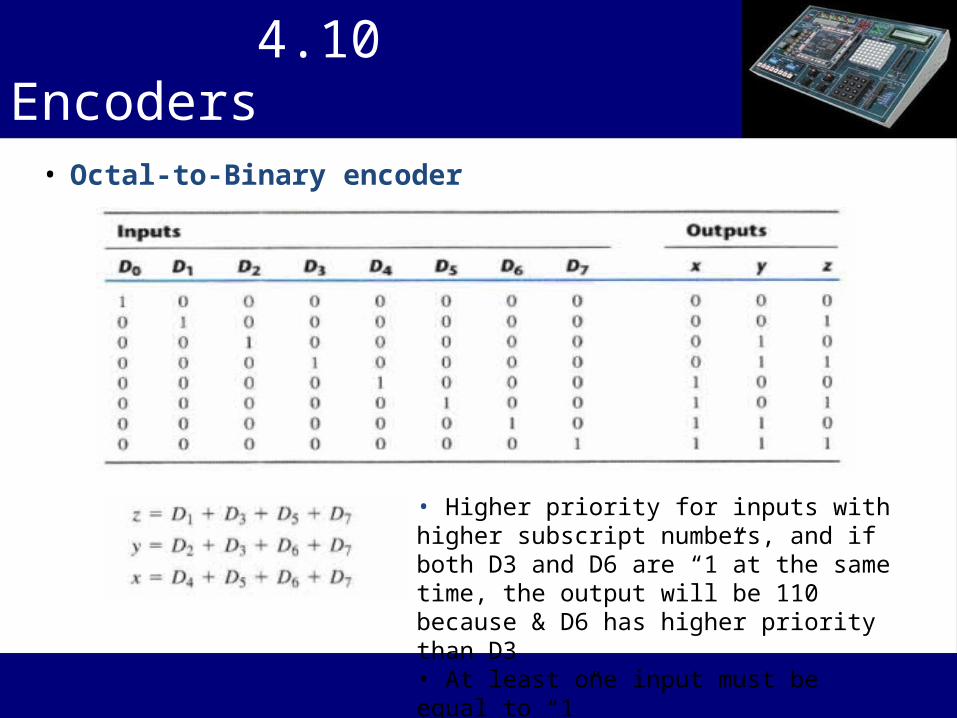
• Octal-to-Binary encoder
4.10 Encoders
• Higher priority for inputs with higher subscript numbers, and if both D3 and D6 are “1”at the same time, the output will be 110 because & D6 has higher priority than D3• At least one input must be equal to “1”

Priority Encoder• A priority encoder is a circuit that includes the priority function• If more than two input equal to “1” , The input having highest priority will take precedence
4.10 Encoders

4.10 Encoders
Maps for priority encoder

• Four input priority encoder Implementation
4.10 Encoders

• A multiplexer is a combinational circuit that selects binary information from one of many input lines and directs it to a single output line• The selection of a particular input line is controlled by a set of selection lines• 2ⁿ input lines and n selection lines whose bit combinations determine which input is selected
4.11 MULTIPLEXERS
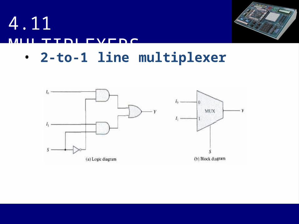
• 2-to-1 line multiplexer
4.11 MULTIPLEXERS

• 4-to-1 line multiplexer
4.11 MULTIPLEXERS
4.11 MULTIPLEXERS
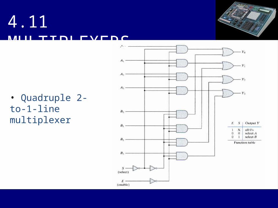
• Quadruple 2-to-1-line multiplexer
Boolean function implementation
• The first n - 1 variables of the function are connected to the selection inputs of the multiplexer• The remaining single variable of the function is used for the data inpute.g. If the single variable (data input) is denoted by , each data input of the multiplexer will be z, z', 1, or 0
4.11 MULTIPLEXERS

Example:
4.11 MULTIPLEXERS

Three state gates
• A multiplexer is constructed with three state gates,(1) Two of the states are Logic 1 & Logic 0(2) The third state is high impedance state in which logic behave like open circuit
4.11 MULTIPLEXERS
Graphic symbol for a three-state buffer

• Multiplexer with three-state gates
4.11 MULTIPLEXERS
4- to – 1 line Mux

Home Exercise
4.21, 4.22, 4.23, 4.25, 4.26, 4.27, 4.28, 4.29, 4.31, 4.32, 4.33, 4.35
Task for next lecture
Write a program and Implement the 4.26 with C /C++