COMBIMASS® Biogas Flowmeter & Analyzer Systems¥ling_af_biogas... · Type 3: Calibration of a...
76
INSA 1 / 14 COMBIMASS® Biogas Flowmeter & Analyzer Systems Introduction BinderGroup COMBIMASS® Flowmeter series Physical Principle Calibration General installation advices Application Biogas COMBIMASS® Flow Conditioner & condensate traps COMBIMASS® Gas Analyzer Portable Analyzer GA-m Docking station GA-s Modular GA-s Click! COMBIMASS® Installation Examples
-
Upload
phungkhanh -
Category
Documents
-
view
217 -
download
0
Transcript of COMBIMASS® Biogas Flowmeter & Analyzer Systems¥ling_af_biogas... · Type 3: Calibration of a...
INSA 1 / 14
COMBIMASS® Biogas Flowmeter & Analyzer Systems
Introduction BinderGroup
COMBIMASS® Flowmeter series Physical Principle Calibration General installation advices Application Biogas
COMBIMASS® Flow Conditioner & condensate traps
COMBIMASS® Gas Analyzer Portable Analyzer GA-m Docking station GA-s Modular GA-s Click!
COMBIMASS® Installation Examples
INSA 2 / 14
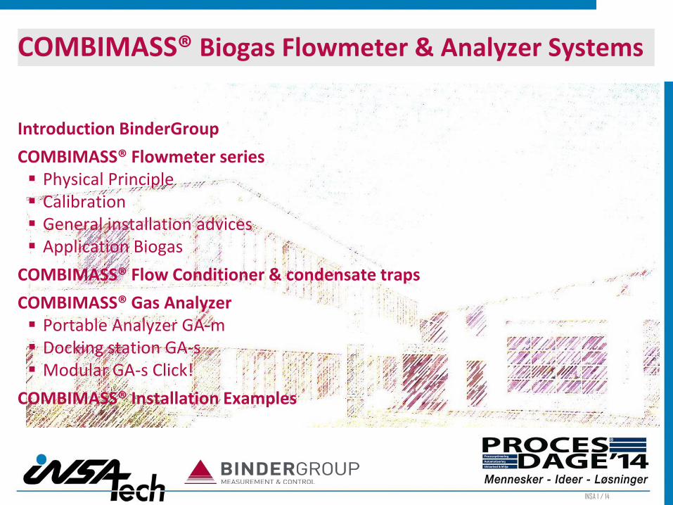
Binder Group AG Finance Holding
BINDER GmbH Manufacturing Company for Gas Flowmeter, Gas Analyzer and Control Systems
with following makes: COMBIMASS® / VACOMASS® / CAMASS®
INSTRUM AG Manufacturing Company for Stainless Steel Pressure Regulators and Valves
Binder Engineering GmbH / Binder Instrumentation Sales & Service Companies in DE/ F/
CH/ NL/ B/ SE Asia / China
BETA B.V. Manufacturing Company for Pressure and Temperature Switches
Overview BinderGroup Ulm, Germany

INSA 3 / 14
Product Line BinderGroup – COMBIMASS® Flow Meter

INSA 4 / 14
without conditioning
with conditioning
Patented Gas Flow Conditioner
Ch
ann
el h
eigh
t C
han
nel
hei
ght
Distance
Distance
Product Line BinderGroup – COMBIMASS® Flow Conditioner
INSA 5 / 14
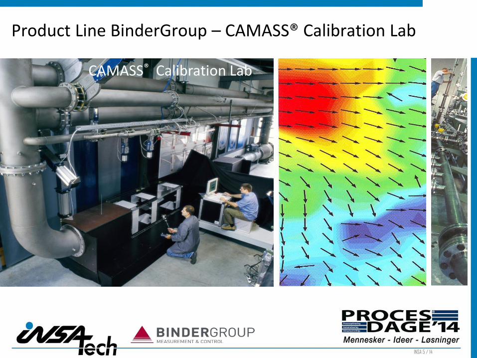
CAMASS® Calibration Lab
Product Line BinderGroup – CAMASS® Calibration Lab

INSA 6 / 14
Product Line BinderGroup – COMBIMASS® Analyzer

INSA 7 / 14
Product Line BinderGroup - VACOMASS® Control System

INSA 8 / 14
for protecting explosive, corrosive and sterile processes with inert gases for liquids and other corrosive media
Product Line BinderGroup - INSTRUM® Pressure Regulators

INSA 9 / 14
Custom built, high quality, user friendly, explosion-proof switches, available in a wide variety with different certificates and approvals
Product Line BinderGroup – BETA Pressure & Temp. Switches

INSA 10 / 14
Sewage Treatment (municipal,
industrial)
Green Energy - Biogas
Chemical Industry
Oil & Gas
Pulp & Paper
Power Generation
Pharma & Biotechnology
Food & Beverages
Textile industry
Automotive
In General:
chemical industry
safety relevant processes
automation & control
high end precision products
Main Markets for BinderGroup Products

INSA 11 / 14
The principle:
Gas flows by a heated sensing element and causes cooling down of the element by the mass flow (molecules)
Temperature:
Measurement is based on a Pt 100, an additional non-heated sensor is used as a reference.
Amount of heat:
The amount is direct related to the mass flow.
Basics of Thermal Dispersion Technology

INSA 12 / 14
COMBIMASS flow meter measure directly in dry gases the standard volumetric flow or the mass flow of the gas respectively according to DIN1343. No pressure and temperature compensation are necessary.
COMBIMASS® sensors for thermal gas flow measurement are designed for minimal pressure loss are rugged, corrosion-resistant require minimal maintenance have no mechanical moving parts
COMBIMASS® sensors are characterized by high-precision resistors minimal drift of the raw signal excellent long-term stability
all this even under harsh operating conditions and at high temperatures.
Basics of Thermal Dispersion Technology - Advantages

INSA 13 / 14
There are 3 different types of biogas flow meters:
COMBIMASS ® eco-bio+ SS (HC)
COMBIMASS ® eco-bio + AL
COMBIMASS ® oem-bio L
with 2 sensor pins, 12 mm diameter, with compression fitting with hot tapping unit and quick sampling connection/ ball valve
COMBIMASS® Biogas Flow meter series

INSA 14 / 14
biogas hat a high percentages of water vapour (at the top of the digester 100% relative humidity) and contains beside others H2S and NH3
the concentration of methane is changing in the biogas
outdoor installation – operation for years under the sky – rain, snow, direct sun light, ...
big plants – long distances between the measuring points
ignition potential of methane-air-mixture
biogas is highly corrosive
COMBIMASS® Biogas flow meter – R&D challenges
Source "Redaktion energie aus pflanzen"

INSA 15 / 14
Gas is damp saturated – based on temperature
Installation places: directly after the digester/ directly after gas cooler
Type: integrated/ external sensor
Based on temperature of the biogas and assuming a relative humidity of 100% the water contents can be calculated by standard method. But gas temperature musn´t be increased due to blowers, direct sun light etc. In these cases temperature method will calculate a wrong (too high) waterdamp portion.
Gas is not damp saturated – based on dew-point
Installation places: after gas storage tank, in front of the CHP
Type: external sensor
Using a special probe, the relative humidity and so the water contents can be determined. The probe is sensitive against H2S, therefore it can be used only after the filter at very low H2S-concentrations.
COMBIMASS® Biogas flow meter – humidity correction

INSA 16 / 14
Temperature in °C
Wat
er c
on
ten
ts in
g /
m³ W
ater con
tents in
Vo
l.-%
COMBIMASS® Biogas flow meter – humidity correction

INSA 17 / 14
Methane concentration in the biogas is changing
Type: correction module/ COMBIMASS® analyzer station
Based on actual CH4-concentration and gas velocity a correction factor is calcu-lated and used for flow correction.
COMBIMASS® Biogas flow meter – flow correction CH4

INSA 18 / 14
The master module has one analog input and one analog output, each 4-20 mA. The flow signal is put into the master module via RX/TX.
Module 1: Humidity correction (for -AL )
based on the 4-20 mA signal of a tempera-ture probe (which can be supplied by Bin-der too) the flow signal is read in and corrected. The analog output will transfer the dry gas flow at standard conditions.
COMBIMASS® Biogas flow meter – correction modules
Module 2: Correction of gas composition
based on the 4-20 mA signal of methane concentration (which is transferred from local gas analysis) the flow signal is read in and corrected. The analog output will transfer actual flow corrected by actual gas composition.
Both corrections cannot be done in one module only!

INSA 19 / 14
no maintenance required
no recalibration required
can be easily cleaned with a brush
always very precise flow measurements,
even when site conditions change (within a specific range)
cost advantages because of modular system
attractive add-ons using gas analysis
rugged design in stainless steel, no moving parts
deposits have few to no influence on the measuring accuracy
the reference sensor measures in each case the process temperature
COMBIMASS® Biogas flow meter – Advantages

INSA 20 / 14
water damp portion is measured too = wet gas flow, but not standard (0% rel. humidity required); if gas is saturated at the installation point, damp portion is only a function of gas temperature
Non-heated sensor is used for measurement of gas temperature, humidity correction is implemented directly in the electronics in the sensor head
sensors are corrosion-proof (SS316 type) & resistant against moisture and dirt
easy installation also in an existing plants, minimal pressure drop
in combination with Binder´s correction modules or gas analyzer station the changing gas composition can be corrected in time
hot tapping units for the sensors available for easy assembly / disassembly under pressure
flow range from 0.25 to 25 m/s at a standard accuracy of 2% of reading
real gas calibration in the CAMASS® Calibration Lab
COMBIMASS® Biogas flow meter – Features

INSA 21 / 14
The COMBIMASS® flow meter can measure very precisely but detect the flow at one point only. Therefore following facts must be considered:
fully turbulent flow - regular flow profile - no flow pulsations no piping pulsations - static gas composition - sufficient straight inlet and outlet piping
Otherwise detected flow can have an error of more than 30%. Different types of COMBIMASS® Flow Conditioner and Condensate Traps can improve the installation situation and so the final accuracy.
COMBIMASS® flow meter – Requirements on the installation place
Total existing straight run
2/3 1/3

INSA 22 / 14
To achieve standard accuracy the shown straight inlet and outlet pipe runs are sufficient. To achieve a better accuracy further please use pipe runs according DIN EN ISO 5167-1.
COMBIMASS® flow meter – Requirements on the installation place

INSA 23 / 14
Preferred position in wet gases is in horizontal pipe sections from side and heated sensor upside
In vertical pipes with wet gases the gas flow should be upstream
Other positions possible, but you must take care that there is no condensate running over the sensor tip (this would cause a high deviation, because the heat capacity of condensated water is much higher than the capacity of the gas)
Vertical piping and downstream gas flow can also be used in diagonal pipe runs or using condensate traps
COMBIMASS® flow meter – Mounting of the sensor in wet gases

INSA 24 / 14
Consequence:
The thermal principle is e.g. suitable also for the measurement of wet gases, like biogas or gas from digesters in sewage treatment plants or landfill gas
Heated sensor point is more warm than environmental gas
Water condensation takes place only at the piping wall
COMBIMASS® flow meter – Mounting of the sensor in wet gases

INSA 25 / 14
Process parameters like temperature, pressure, installation details of piping and gas composition will be considered always to achieve a high accuracy of flow metering. Type 1: Standard-Calibration of the COMBIMASS® flow meter under actual operating conditions in our CAMASS® Calibration Lab. This standard calibration will be done under the assumption that sufficient inlet and outlet straight pipe runs are available for installation of the COMBIMASS®flow meter.
Type 2: Calibration of the COMBIMASS® multi flow meter under actual operating conditions in our CAMASS® Calibration Lab.
Type 3: Calibration of a COMBIMASS® flow meter including simu-lation of the actual piping isometry (scale 1:1).
Type 4: Calibration of a COMBIMASS® flow meter in combination with the COMBIMASS® flow conditioner as a complete unit.
COMBIMASS® Flow meter – Types of calibration
INSA 26 / 14
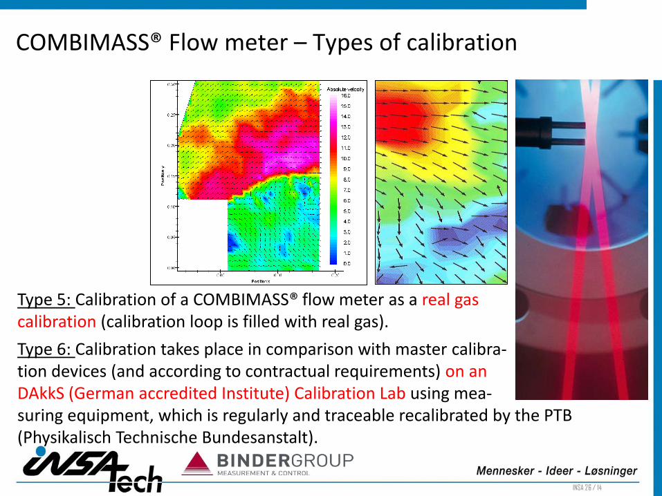
Type 5: Calibration of a COMBIMASS® flow meter as a real gas calibration (calibration loop is filled with real gas).
Type 6: Calibration takes place in comparison with master calibra- tion devices (and according to contractual requirements) on an DAkkS (German accredited Institute) Calibration Lab using mea- suring equipment, which is regularly and traceable recalibrated by the PTB (Physikalisch Technische Bundesanstalt).
COMBIMASS® Flow meter – Types of calibration
INSA 27 / 14
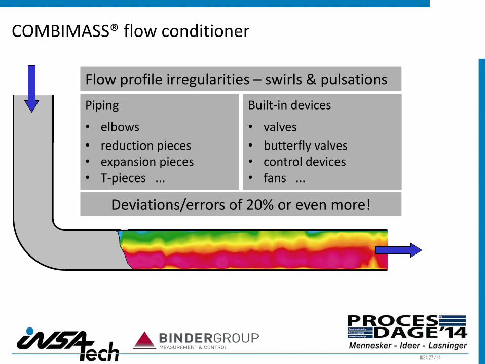
Flow profile irregularities – swirls & pulsations
Built-in devices
• valves
• butterfly valves • control devices • fans ...
Piping
• elbows
• reduction pieces • expansion pieces • T-pieces ...
Deviations/errors of 20% or even more!
COMBIMASS® flow conditioner

INSA 28 / 14
COMBIMASS® SCS-Principle
S wirl reduction
C ross flow conditioning
S moothing /damping of pulsations 1
3 2
COMBIMASS® flow conditioner

INSA 29 / 14
precise measuring results even at unfavourable installation position of the flow meter
flow conditioning after 3 – 7*D only
minimal pressure loss
rugged and unsensitive to dirt
Made in stainless steel – corrosion resistant
available for installation in pipes and rectangular air ducts
available as a flange version or for insertion only
... for excellence in accuracy and measuring certainity
COMBIMASS® flow conditioner

INSA 30 / 14
COMBIMASS® condensate traps for vertical pipe runs
fully made in stainless steel
with integrated condensate removal
for installation in vertical pipe runs
reliable and rugged design

INSA 31 / 14
COMBIMASS® GA-m – The instrument
Standard biogas configuration: 2xIR CH4 0-100%/ CO2 0-100% 2xEC O2 0-25%/ H2S 0-2,000 ppm
Additional gas cells: H2 0-1,000 ppm / CO 0-1,000 or 0-2,000 ppm

INSA 32 / 14
optical infrared analysis
measurement of up to 7 gas components
high performance measuring gas pump
easily exchangeable measuring gas micro-filter
up to 5 sensors plug-in and calibrated
optionally CO and H2-cells available
upgrade to an automatic, stationary analyzer system with up to 13 gas sampling points plus 1 for test gas as well as integrated measurement of flow and data seizure
COMBIMASS® GA-m – Features of the portable instrument

INSA 33 / 14
at different places applicable, data can be stored measuring point-specifically snap
simple operation
rugged technology, maintenance-poor,
simple maintenance
integration of other measurements like gas flow, gas temperature & pressure possible
correction of flow signal by actual gas composition integrated
measuring data recording, PC - evaluation
ATEX certified
COMBIMASS® GA-m – Features of the portable instrument

INSA 34 / 14
data transmission cable and Siteman-software
temperature sensor measuring range: 0 – 100°C
portable COMBIMASS flow meter eco-bio+ (up to DN400 pipe, up to 12,000 Nm³/hr, with integrated humidity correction – gas quality compensation in
the GA-m)
hot tapping unit with quick coupling or small ball valve
pressure controller, if gas pressure is above 30 mbar
filter shall be used in case of water drops in the gas flow
temperature/flow in
gas out
gas in battery charger
COMBIMASS® GA-m – Acessories

INSA 35 / 14
battery pack
external filter
internal filter
electrochemical cells
sampling hose
gas pump
plastic couplings
COMBIMASS® GA-m – Spares and wearing parts

INSA 36 / 14
All analyzer equipment requires service: recalibration, replacement of electrochemical cells, filters, pumps, etc.
Binder offer maintenance contracts with replacement of all usual wearing parts
Binder offers furthermore a „Priority service“ for customers without maintenance contracts (with 12 months new manufacturer´s warranty, except wearing parts)
Binder offers a service case by case (ticketing system for booking in)
For the duration of service/repair Binder offers spare analyzer
COMBIMASS® GA-m – Service, Maintenance and Repair

INSA 37 / 14
COMBIMASS® GA-s Dockingstation with GA-m/ GA-e

INSA 38 / 14
The standardized Docking station contains:
cabinet 400x400 with SPC and display, 24 VDC
required valves etc. for 2 gas sampling points
4 analog inputs for 2x flow and 2x temperature/humidity
1 measuring gas pump on strip
1 flushing valve
1 test gas connectivity
1 cabinet exhaust
gas and rinsing air are feed into the environment
operation over touchscreen or using 6 keys
menus and manuals in several languages available
without analyzer instrument
COMBIMASS® GA-s – Standard configuration

INSA 39 / 14
“2-in-1” solution for easy maintenance: customer gets a spare analyzer and sends the analyzer to Ulm – service at site can be done by a technician or electrician
for GA-m analyzer with CH4/ CO2/ O2/ H2S/ (H2) or GA-e analyzer CH4/ (CO2/) O2/ H2S
can be expanded up to 13 measuring points (in a bigger cabinet)
Furthermore up to 13 flow and temperature/ humidity signals can be read in via DIN-rail modules, flow signals will get compensated automatically by actual gas composition
24 VDC/230 VAC external power supply box
Communication: Ethernet Modbus TCP, Modbus RTU/ RS485, Profibus DP, Analog signals 4-20 mA
COMBIMASS® GA-s – Features
INSA 40 / 14
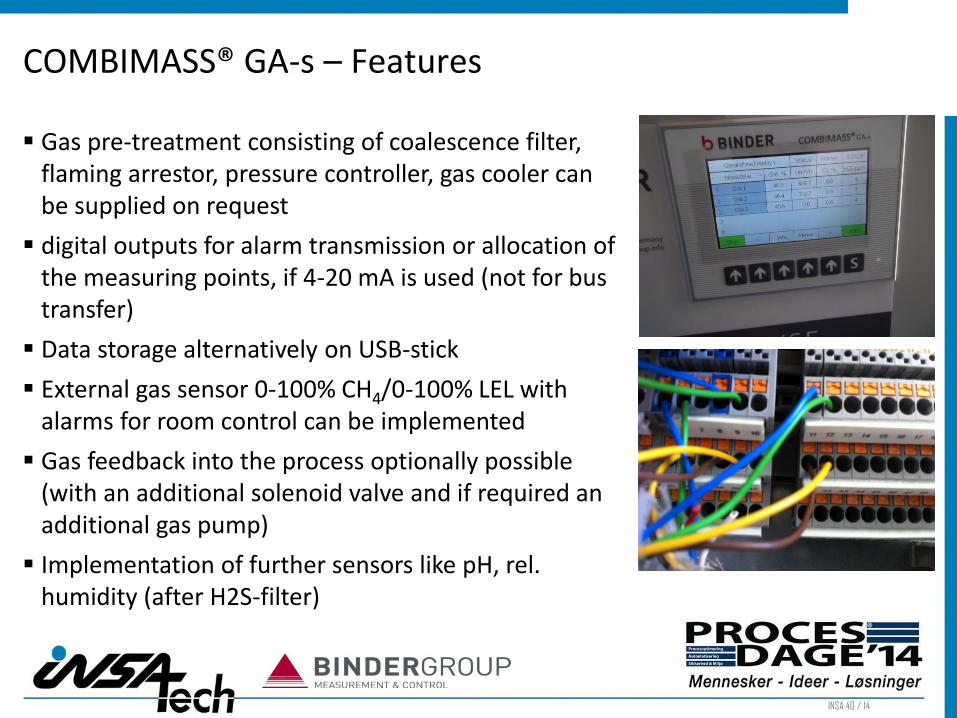
Gas pre-treatment consisting of coalescence filter, flaming arrestor, pressure controller, gas cooler can be supplied on request
digital outputs for alarm transmission or allocation of the measuring points, if 4-20 mA is used (not for bus transfer)
Data storage alternatively on USB-stick
External gas sensor 0-100% CH4/0-100% LEL with alarms for room control can be implemented
Gas feedback into the process optionally possible (with an additional solenoid valve and if required an additional gas pump)
Implementation of further sensors like pH, rel. humidity (after H2S-filter)
COMBIMASS® GA-s – Features

INSA 41 / 14
common alarm for leakages, over/falling below set points as well as ventilation fault
key to store and protect configuration data
climatized cabinet for outdoor- installation as an option (incl. air cooling/heating and LEL- control of the cabinet)
External access to the analyzer menus via direct Ethernet wiring, internet connection or GSM/GPRS
Additional hard- und software for control of filling level of gas storage tank as well as load-depending dosing of feedstock to the biogas plant (10% savings in feedstock can be expected)
COMBIMASS® GA-s – Features
INSA 42 / 14
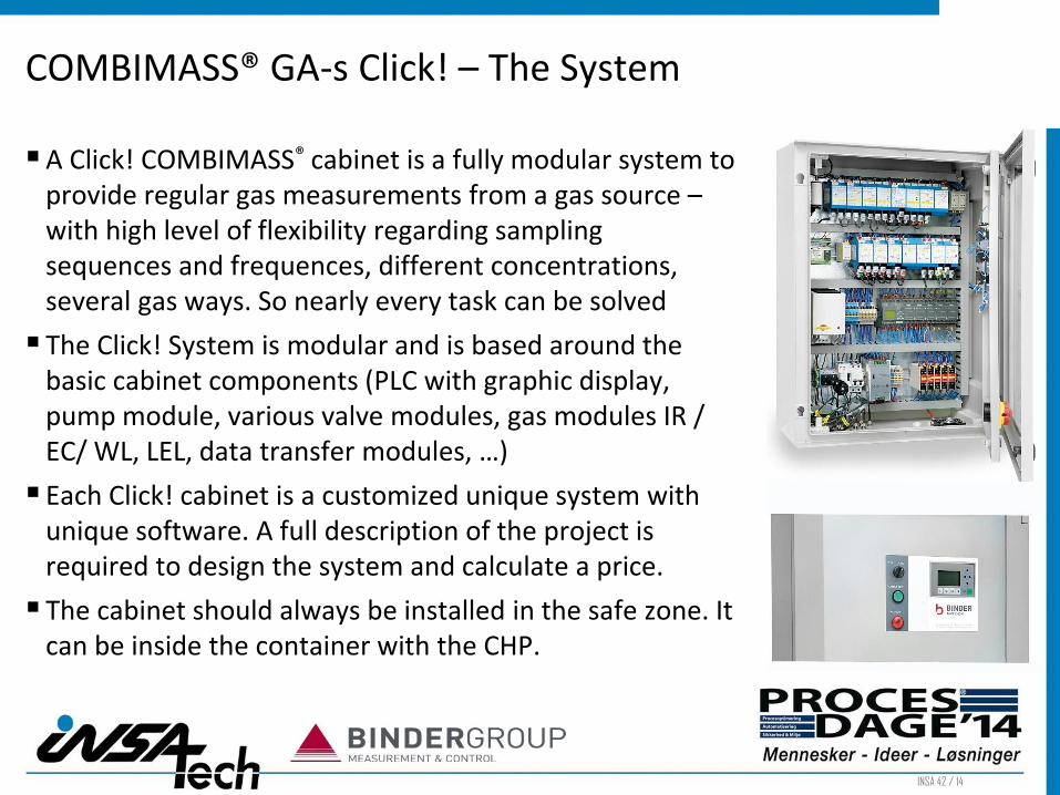
A Click! COMBIMASS® cabinet is a fully modular system to provide regular gas measurements from a gas source – with high level of flexibility regarding sampling sequences and frequences, different concentrations, several gas ways. So nearly every task can be solved
The Click! System is modular and is based around the basic cabinet components (PLC with graphic display, pump module, various valve modules, gas modules IR / EC/ WL, LEL, data transfer modules, …)
Each Click! cabinet is a customized unique system with unique software. A full description of the project is required to design the system and calculate a price.
The cabinet should always be installed in the safe zone. It can be inside the container with the CHP.
COMBIMASS® GA-s Click! – The System

INSA 43 / 14
It can indoors or outdoors. They can be wall mounted or free standing.
Autocalibration Check / Autocalibration Function
Only a small part of the sampled gas is used for analysis. The excess gas is fed directly into the environment. So the wear of electrochemical cells becomes less.
All standard data transmission kinds are available: Profibus DP, Modbus RTU, Modbus TCP, 4-20 mA,…
There are 3 general types of gas modules: Infra red: CH4, CO2 Electrochemical cells: O2, H2S, (NH3), CO Heat conductivity: H2, CO (0-30 Vol.-% High Range)
COMBIMASS® GA-s Click! – The System

INSA 44 / 14
All modules can be easily adjusted for the zero point and span by the installer/maintainer to ensure optimum accuracy.
Gas modules require at minimum an annual check/ refurbishment, pump and valve modules should be serviced according to Binder´s recommendations
ensure spare modules available at site, “old” modules can be refurbished at low costs
Remove connections (hoses and wires for Gas IN , Gas OUT, Power supply, AO) and click out old module - click in replacement module and reconnect hoses and wires
Binder will refurbish the module and send it back to you/your customer for stock
COMBIMASS® GA-s Click! – Service and maintenance
INSA 45 / 14
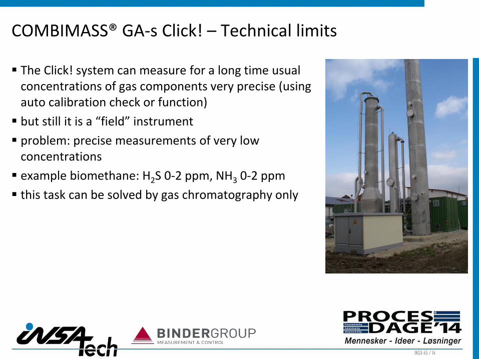
The Click! system can measure for a long time usual concentrations of gas components very precise (using auto calibration check or function)
but still it is a “field” instrument
problem: precise measurements of very low concentrations
example biomethane: H2S 0-2 ppm, NH3 0-2 ppm
this task can be solved by gas chromatography only
COMBIMASS® GA-s Click! – Technical limits

INSA 46 / 14
Installation Examples Biogas Flow Meter and Analyzer
Flow metering and Analysis of Biogas: Digester / Flare / H2S-Filter-Control / Control of gas quality in front of the CHP/ Gas2Grid – biomethane into natural gas grid
Flexible Solutions for co-fermentation plants, solid waste / composting plants
Anaerobic pre-treatment of industrial sewage
Flow metering and Analysis of digester gas from WWTP´s
Flow metering and Analysis of landfill gas
R&D projects

INSA 47 / 14
Reduction of C-Load of industrial effluent
Production of process heat and energy
Reduction of energy costs for biological sewage treatment in the own plant / reduction of BOD-load in the effluent
Reduction of costs for sludge treatment and storage
combined gas flow metering and analysis

INSA 48 / 14
Application Biogas Plant:
Typical installations: Gas flow metering and analysis of each single digester, in front of the flare, in front of the CHP, H2S-filter control

INSA 49 / 14
Examples – Biogas Gas from anaerobic digestion of manure, crops etc., DE

INSA 50 / 14
Examples – Biogas Gas from anaerobic digestion of manure, crops etc., DE, IT
INSA 51 / 14
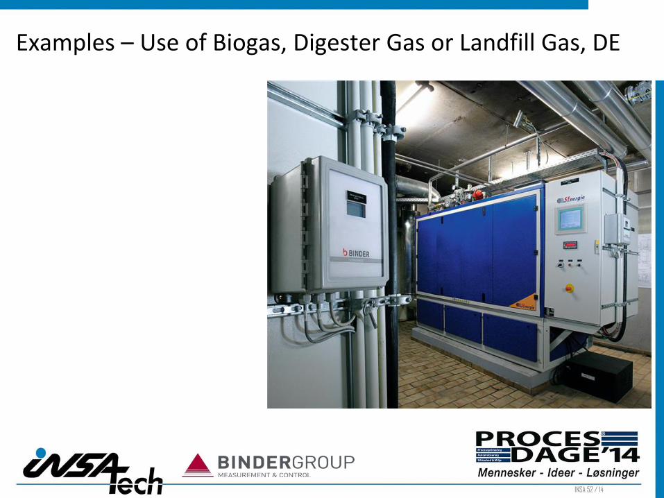
Control of gas quality and flow in front of CHP´s
Control of H2S-concentration/ Removal to reduce costs for wear and increase maintenance time cycles
Control of the CHP-efficiency factor
Reduction of costs for insurances
Typical installation: Gas flow metering and analysis with calibration function for gas cells with testgas
INSA 52 / 14
Examples – Use of Biogas, Digester Gas or Landfill Gas, DE

INSA 53 / 14
Gas-2-grid Installations – Feed of biomethane to the natural gas grid
Typical installation: gas flow metering and analysis to control each step of treatment (H2S-removal, CO2-Reduction, Removal of moisture, pressure increase)
Special requirements: high accuracy and repeatability (use of flow conditioners, special calibration of flow meter, (auto)calibration of gas cells)

INSA 54 / 14
Examples – Upgrade of Biogas to Biomethane, DE

INSA 55 / 14
Flexible Solutions for Co-Fermentation plants, solid waste treatment/ composting plants
- Use of the Click! system for advanced requirements for flexibility, availability and further special features
- Typical installations: Gas flowmetering and analysis with autocalibration check/function for gas cells with several test gases

INSA 56 / 14
Examples – Various installations of GA-s Click! Systems, U.K.

INSA 57 / 14
Hydro- lyse 1
Fer-menter
1
Hydro-lyse 2
Fer-menter
2
1 Cogene-
rator
2 3
4 5
GA-s Click !
Sampling Cycles: 1. Gas 1:CH4/ CO2/ O2/ H2S/ NH3 - every 120 minutes 2. Gas 2:CH4/ CO2/ O2/ H2S/ NH3 - every 12 hours 3. Gas 3:CH4/ CO2/ O2/ H2S/ NH3 - every 12 hours 4. Gas 4:CH4/ CO2/ O2/ H2S/ H2 0-30% - every 24 hours 5. Gas 5:CH4/ CO2/ O2/ H2S/ H2 0-30% - every 24 hours
Examples – Co-Fermentation plant (crops + old food), BE

INSA 58 / 14
Examples – Co-Fermentation plant (crops + old food), BE
Gas Flow Scheme and Cabinet Layout

INSA 59 / 14
12 Boxes for acidification and one further tank for methanezation 12 sampling points for the boxes and 3 further sampling points in collection pipes in front and after the methane reactor, after H2S-filter incl. 3 gas flow meter
Examples – 2-stage solid waste and composting plant, NL

INSA 60 / 14
General data transfer: Profibus All Menues on the PC-Screen in the control room 12 Boxen shall be analyzed every 15 minutes “Quick sampling” every 5 minutes for actual open box Sampling points 13 to15 up to 150 m away from cabinet
Examples – 2-stage solid waste and composting plant, NL

INSA 61 / 14
Examples – 2-stage solid waste and composting plant, NL
Gas Flow Scheme and Cabinet Layout

INSA 62 / 14
Examples – 2-stage solid waste and composting plant, NL

INSA 63 / 14
Examples – Solid waste digestion plants, DE
INSA 64 / 14
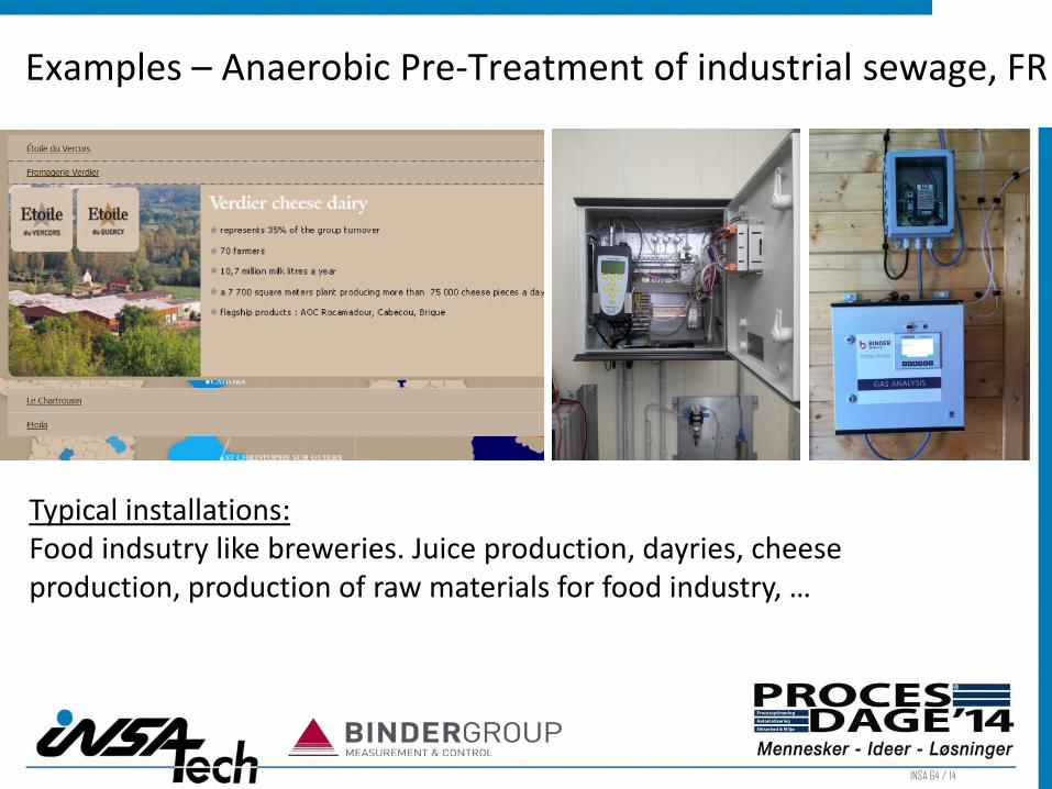
Typical installations: Food indsutry like breweries. Juice production, dayries, cheese production, production of raw materials for food industry, …
Cheese production France
Examples – Anaerobic Pre-Treatment of industrial sewage, FR

INSA 65 / 14
Examples – Anaerobic Pre-Treatment of palm oil effluent, MY
Place of installation: Malaysia Official governmental test plant

INSA 66 / 14
Examples – Anaerobic Pre-Treatment of palm oil effluent, IN
Place of installation: Indonesia Customer: Palm Oil Manufacturer

INSA 67 / 14
Gas from SP “1, 2 and 3” are situated directly after the digester (raw biogas), “4” is gas coming from hydrolysate tank, “5” is gas sampled after the H2S-removal and “6” after the gas storage tank in front of the cogenerator. H2S-level in the raw gas can be up to 3,000ppm, but “5 and 6” may be expected to have H2S up to 100ppm. In order to be able to measure each level of gas precisely, each gas stream would need to be measured with a different range of H2S module.
air
Desul-phuri zation
Gas storage tank
Cogeneration
SP1 SP2 SP3 Flow 1 Flow 2 Flow 3
SP5
SP4 Flow 4
SP6 Flow 5
Hydrolys. Digester 1 Digester 2 Digester 3 Tank post f.
Examples – Anaerobic Pre-Treatment of palm oil effluent, IN
Measuring sequences:
1. Sampling point 1-5: CH4/ CO2/ O2/ H2S - every 60 minutes
2. Sampling point 6: CH4/ CO2/ O2/ H2S - every 30 minutes
3. Calibration gas 1: 60% CH4/ 40% CO2/ 3,000 ppm H2S every 72 hours autocalibration
4. Calibration gas 2: 100 ppm H2S/ 100% N2 every 24 hours autocalibration

INSA 68 / 14
Examples – Anaerobic Pre-Treatment of palm oil effluent, IN
Gas Flow Scheme and Cabinet Layout

INSA 69 / 14
Application Wastewater Treatment Plant - Digester
Reduction of external supply of electrical energy due to digesting and incineration of sludge
Installation of gas flow meter and analyzer closed to the digester, in front of the CHP, in front of the flare, control of gas treatment (H2S-filter)

INSA 70 / 14
Examples – Digester Gas from sewage treatment plants, DE
Typical installation places are: directly after the digester in front of the flare in front and after the H2S-filter in front of the CHP

INSA 71 / 14
Examples – Digester Gas from sewage treatment plants, DE

INSA 72 / 14
Application Landfill
Gas flow metering and analysis of single boreholes and in collection pipes
energy and heat production reduces operations costs
typical installation: portable flow meter and handheld analyzer for boreholes and fields, Dockingstation „2-in-1“ for analysis of gas in collection pipes

INSA 74 / 14
Application R&D Projects
Gas flow metering and analysis to achieve highest accuracy and repeatability
Investigation of gas production of various feed stocks etc.

INSA 75 / 14
Combination of gas flow metering and analysis for best accuracy (gas com position unknown and changes in time)
Examples – R&D project „hygienization“, DE

INSA 76 / 14
Thank you for your attention! Any Questions? Manuela Charatjan Manager Process Engineering Binder GmbH 89187 Ulm Buchbrunnenweg 18 Germany [email protected] www.bindergroup.info