Com Using Icom m710 m710rt
25
USING THE ICOM IC – M710 and 710RT MARINE SSB RADIOS Revised July 2006 Walter R. Paul Disclaimer: This document was compiled from information supplied by members of the Cruising Club of America and from various publications and websites to which the reader is referred for more detailed and current information. While the Club has no reason to believe that any of the information is inaccurate, it has not confirmed the accuracy or completeness of the information and makes no representation with respect thereto. Furthermore, this document does not purport to supply all of the information someone should have before embarking on an offshore passage. Note: Reference to a commercial product or service does not imply any endorsement by the Cruising Club of America as to function or suitability for any purpose or environment.
Transcript of Com Using Icom m710 m710rt

8/6/2019 Com Using Icom m710 m710rt
http://slidepdf.com/reader/full/com-using-icom-m710-m710rt 1/25
USING THE
ICOM IC – M710 and 710RT
MARINE SSB RADIOS
Revised July 2006
Walter R. Paul
Disclaimer: This document was compiled from information supplied by members of the CruisingClub of America and from various publications and websites to which the reader is referred formore detailed and current information. While the Club has no reason to believe that any of theinformation is inaccurate, it has not confirmed the accuracy or completeness of the information andmakes no representation with respect thereto. Furthermore, this document does not purport tosupply all of the information someone should have before embarking on an offshore passage.
Note: Reference to a commercial product or service does not imply any endorsement by theCruising Club of America as to function or suitability for any purpose or environment.
8/6/2019 Com Using Icom m710 m710rt
http://slidepdf.com/reader/full/com-using-icom-m710-m710rt 2/25
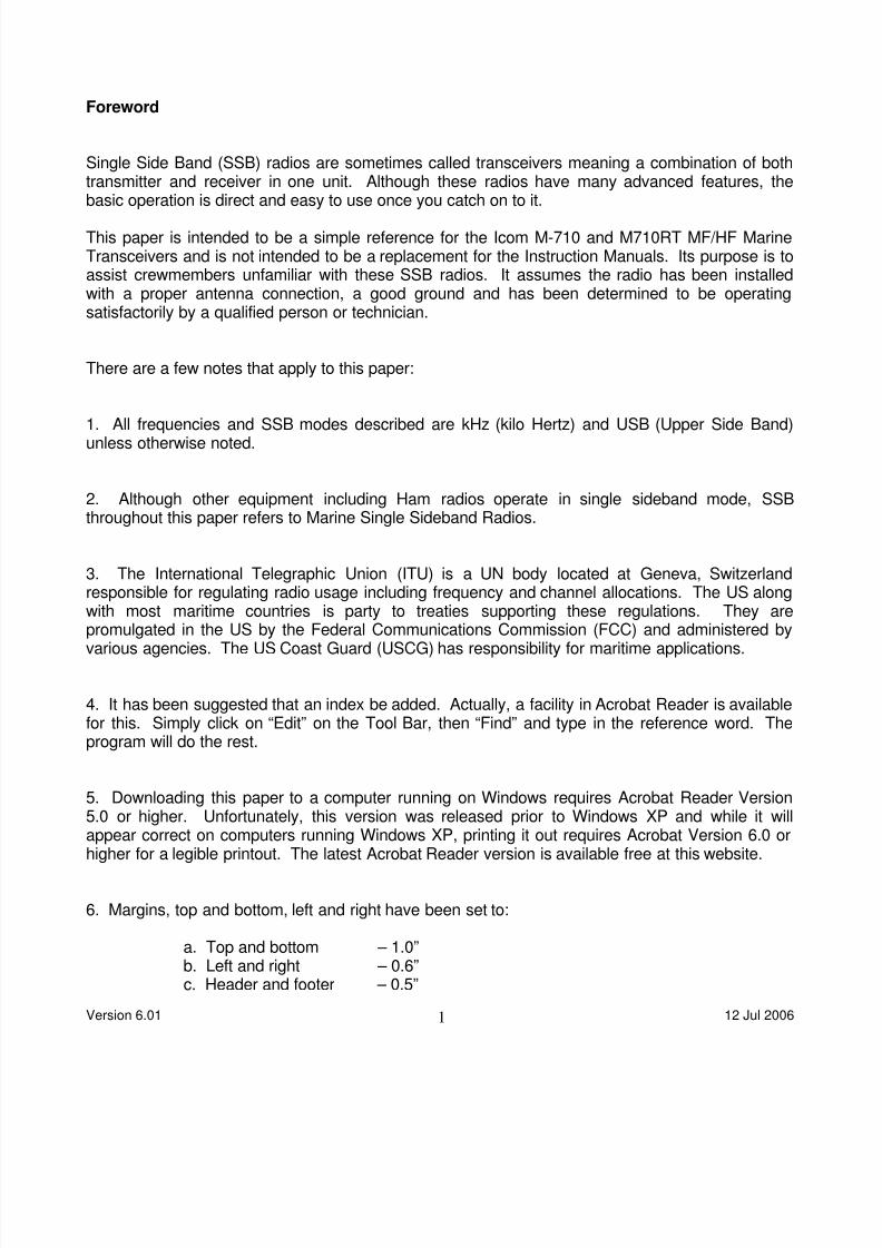
Foreword
Single Side Band (SSB) radios are sometimes called transceivers meaning a combination of bothtransmitter and receiver in one unit. Although these radios have many advanced features, the
basic operation is direct and easy to use once you catch on to it.
This paper is intended to be a simple reference for the Icom M-710 and M710RT MF/HF MarineTransceivers and is not intended to be a replacement for the Instruction Manuals. Its purpose is toassist crewmembers unfamiliar with these SSB radios. It assumes the radio has been installedwith a proper antenna connection, a good ground and has been determined to be operatingsatisfactorily by a qualified person or technician.
There are a few notes that apply to this paper:
1. All frequencies and SSB modes described are kHz (kilo Hertz) and USB (Upper Side Band)unless otherwise noted.
2. Although other equipment including Ham radios operate in single sideband mode, SSBthroughout this paper refers to Marine Single Sideband Radios.
3. The International Telegraphic Union (ITU) is a UN body located at Geneva, Switzerlandresponsible for regulating radio usage including frequency and channel allocations. The US alongwith most maritime countries is party to treaties supporting these regulations. They arepromulgated in the US by the Federal Communications Commission (FCC) and administered byvarious agencies. The US Coast Guard (USCG) has responsibility for maritime applications.
4. It has been suggested that an index be added. Actually, a facility in Acrobat Reader is availablefor this. Simply click on “Edit” on the Tool Bar, then “Find” and type in the reference word. Theprogram will do the rest.
5. Downloading this paper to a computer running on Windows requires Acrobat Reader Version5.0 or higher. Unfortunately, this version was released prior to Windows XP and while it willappear correct on computers running Windows XP, printing it out requires Acrobat Version 6.0 orhigher for a legible printout. The latest Acrobat Reader version is available free at this website.
6. Margins, top and bottom, left and right have been set to:
a. Top and bottom – 1.0”b. Left and right – 0.6”c. Header and footer – 0.5”
Version 6.01 12 Jul 20061

8/6/2019 Com Using Icom m710 m710rt
http://slidepdf.com/reader/full/com-using-icom-m710-m710rt 3/25
7. Additional information about using a marine SSB, that is what to do with it once you know howto use it may be found in “Offshore Communications Memorandum” and the paper “Frequencies,Nets, WX Schedules and Tables”, formerly titled the “Appendix” at this CCA website,www.cruisingclub.org under the sidebar “Offshore Communications and Electronics”.
8. Information about "SSB Transmissions, Connections and Grounds" may also be found at thatsame sidebar.
My thanks to R. Steven Thing and Bill Cote who reviewed the original draft along with others whohave written about the content since then.
Comments, corrections and suggestions are more than welcomed and I try to respond to each ofthese when received. Since we spend as much time as we can on our boat, please send them tome via email.
Have a good time with these great radios.
Walt [email protected]
ChairOffshore Communications and ElectronicsCruising Club of America
July 2006
Version 6.01 12 Jul 20062

8/6/2019 Com Using Icom m710 m710rt
http://slidepdf.com/reader/full/com-using-icom-m710-m710rt 4/25
CHANGES AND CORRECTIONS
Major changes, additions and corrections in this version are highlighted in YELLOW where
practical to assist in recognizing them. Where a new section or paragraph has been added, thetitle in the Table of Contents and the title (only) in the body of the paper are highlighted.
Version 5.01
Revised version numbering (year – issue)
Revised reference to the USCG Distress and Safety Watchkeeping Channels to reflect the changeeffective 1 Jan 05
Minor editorial corrections and reorganization
Version 6.01
Editorial clean-up and minor corredtions
Version 6.01 12 Jul 20063

8/6/2019 Com Using Icom m710 m710rt
http://slidepdf.com/reader/full/com-using-icom-m710-m710rt 5/25
TABLE OF CONTENTS
Page
1 Introduction …………………………….………………………………………………. 6
2 The Icom Dealer …………………………………………………………………..….... 6
3 Just A Little Technical Background For The Unfamiliar ………………….....… 6
4 How The Radio Is Organized ……….……………………………………….…........ 6
5 In Practice …………..………………………………………………………………….. 8
6 The International Distress, Safety and Hailing Frequencies ………………….. 9
6.1 The USCG Working Channels ……………………………………………. 10
7 Getting Started …………………………………………………..…………………..… 10
7.1 The User Programmable Channels ....................................................... 117.2 The Duplex Channels ..………………………..…….…..………………... 117.3 More On Selecting ITU Dup0lex Channels ……………………………. 137.4 The Associated Simplex channels …………………………………….… 14
8 Operating The Radio ………………………………..………….………….…………... 15
8.1 Frequency / Channel Presentation …………………...………………...... 158.2 The RX Icon ………..……………..…………………..…..…………………. 16
8.3 Simplex, Duplex or Blank …….…………………...................................... 16
9 The Buttons Under The Display …………………………………….…..................... 17
9.1 The Mode Button (Emission Mode) ……….………..…...……………..… 179.2 The Other Buttons ……………………………………..….....................… 18
9.2.1 AGC …………….………….…………….……..…………………. 189.2.2 NB …..………….……………………….…...…………………….. 189.2.3 SQL ……………………………………….……..................…….… 189.2.4 FUNC ……..…………………………….……...………………….. 189.2.5 TUNE ………………………..……….……..……………………... 18
10 The Keypad ……....………………………………….………….………………..…….. 19
10.1 CE …..……..….…………………………….………………...................... 1910.2 Dash Symbol “-“ ………...………………….…..……….……..………….… 1910.3 RX ……………………….…………………..…………….……..…………... 1910.4 Direct Dialing …….……………………….……………..………….……….... 2010.5 TX ……….………………………..……….………….………………………... 20
Version 6.01 12 Jul 20064

8/6/2019 Com Using Icom m710 m710rt
http://slidepdf.com/reader/full/com-using-icom-m710-m710rt 6/25
11 Changing Programmable Frequencies ……………..….……………..............…. 20
11.1 To Change An RX ……………………….……………….………………. 2011.2 To Change A TX ……...……………………….…………….…………. 21
12 The M710RT Microphone …………………….…………….….…..………............ 22
11.1 Channel selection Buttons …………….…………………………............ 2211.2 P Switch ….…….………………………….……………………………….… 2211.3 Push To Talk ….……………………….…………………………………….. 22
13 Transmitting ..…………………………………….……………………...……………. 23
Version 6.01 12 Jul 20065
8/6/2019 Com Using Icom m710 m710rt
http://slidepdf.com/reader/full/com-using-icom-m710-m710rt 7/25
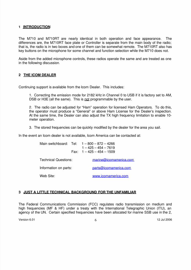
1 INTRODUCTION
The M710 and M710RT are nearly identical in both operation and face appearance. Thedifferences are, the M710RT face plate or Controller is separate from the main body of the radio;that is, the radio is in two boxes and one of them can be somewhat remote. The M710RT also haskey buttons on the microphone for some channel and function selection while the M710 does not.
Aside from the added microphone controls, these radios operate the same and are treated as onein the following discussion.
2 THE ICOM DEALER
Continuing support is available from the Icom Dealer. This includes:
1. Correcting the emission mode for 2182 kHz in Channel 0 to USB if it is factory set to AM,DSB or H3E (all the same). This is not programmable by the user.
2. The radio can be adjusted for “Ham” operation for licensed Ham Operators. To do this,the operator must produce a “General” or above Ham License for the Dealer’s inspection.At the same time, the Dealer can also adjust the TX high frequency limitation to enable 10-meter operation.
3. The stored frequencies can be quickly modified by the dealer for the area you sail.
In the event an Icom dealer is not available, Icom America can be contacted at:
Main switchboard: Tel: 1 – 800 – 872 – 42661 – 425 – 454 – 7619
Fax: 1 – 425 – 454 – 1509
Technical Questions: [email protected]
Information on parts: [email protected]
Web Site: www.icomamerica.com
3 JUST A LITTLE TECHNICAL BACKGROUND FOR THE UNFAMILIAR
The Federal Communications Commission (FCC) regulates radio transmission on medium andhigh frequencies (MF & HF) under a treaty with the International Telegraphic Union (ITU), anagency of the UN. Certain specified frequencies have been allocated for marine SSB use in the 2,
Version 6.01 12 Jul 20066

8/6/2019 Com Using Icom m710 m710rt
http://slidepdf.com/reader/full/com-using-icom-m710-m710rt 8/25
4, 6, 8, 12, 16, 18, 22 and 25 mega Hertz (MHz) ranges or bands. These frequencies dovetail withsome of the authorized Amateur Radio Operator (“Ham”) frequency bands, but are not the sameand do not overlap.
Transmit (TX) and Receive (RX) frequencies are sometimes thought of as “pairs” and are assigned
together to a channel in the radio’s memory. Each channel is numbered for easy identification.The more channels in a radio, the more pairs of frequencies can be stored and directly accessedrather than keying in or dialing new TX and RX frequencies each time there is a need to changefrequencies.
When a "pair" or both a TX and RX frequency in a channel are the same, the channel is called “asimplex channel”. In this type of operation, a listener hears everything spoken by either party.
When the TX and RX frequencies are different, the channel is called “a duplex channel” andnormally only one side of the conversation can be heard by a listener. Duplex channels are mainlyused to communicate to shore side stations and provide a degree of confidentiality.
4 HOW THE RADIO IS ORGANIZED
The memory in this radio has been allocated into three separate groups. For want of betternames, they are the "User Programmable Channels", the "ITU Duplex Channels" along with their"Associated Simplex Channels" and the "FSK Channels".
Memory Organization Concept:
USER PROGRAMMABLE CHANNELS
DUPLEX CHANNELS
ASSOCIATED SIMPLEX CHANNELS
FSK CHANNELS
As with many things in life, there are some exceptions and variations:
Version 6.01 12 Jul 20067

8/6/2019 Com Using Icom m710 m710rt
http://slidepdf.com/reader/full/com-using-icom-m710-m710rt 9/25
1. Channel 0 is unique and outside these three memory banks. Channel 0 is reserved for
the Emergency Channel, 2182.0 kHz and is selected via the two or three buttons abovethe Volume knob. It is not user programmable.
2. User Programmable Channels: There are 160 programmable channels available whichcan be either simplex or duplex and can use any type emission (called mode) available
to the radio.
3. Attached to each ITU Duplex Channel range are 9 "Associated Simplex Channels".These channels are programmable, but only in simplex in the same frequency bandand are discussed later.
4. FSK Channels: The third section of the radio memory contains 662 channels forFrequency Shift Keying (FSK) operations. These channels are numbered from 4001 to25040, stratified by frequency bands with a varying number of frequencies allocated tothe bands. They are located between Channels 25 – 9 and Channel 1.
FSK Channels are required for some accessories and specialized equipment. Mostyachts do not have a need or use for these channels and many dealers will disable thissection to avoid operator confusion. For instructions on how to hide this section of theradio (recommended), see page 13 of the Instruction Manual under SET MODE (1).
We want to note the existence of the FSK Channels section, but will not discuss it on theassumption it has been disabled.
5 In Practice
Yachts with marine SSB radios talk to other yachts in simplex mode and always Upper Side Band(USB). Weather faxes, voice weather forecasts, news broadcasts from Voice Of America or BBCcan all be received on USB although that may not be the primary emission mode. Although therecould be, there is normally no transmit frequency for these channels.
Generally, yachts talk to each other in the 4 and 6 MHz frequency ranges and sometimes even ashigh as the 8 MHz frequencies depending on the distance. Some long-range SSB nets use one ofthe 12 MHz frequencies, but they are the exception. The higher frequencies usually mean greaterrange, but at a price; these signals normally “skip” over the top of yachts close in where yourfriends are who then can’t receive the transmission. There is no such thing as a free lunch.
In the Caribbean, most SSB traffic and nets are on 4 or 6 MHz and the calling frequency is 6215kHz, the calling and safety frequency. In the Mediterranean, most traffic is 8 MHz because of theadded distance and many yachts use 8122 kHz for a calling frequency, particularly after themorning cruiser’s net.
Some yachts use their SSB to make high seas telephone calls or send and receive e-mail viashore stations. Operations with shore stations normally involve duplex channels and are USB.
Version 6.01 12 Jul 20068

8/6/2019 Com Using Icom m710 m710rt
http://slidepdf.com/reader/full/com-using-icom-m710-m710rt 10/25
Doing email normally requires an accessory like a modem to manage the data. More details onthis are covered in the primary paper in this series, “Offshore Communications Memorandum”.
Local radio broadcast stations are normally AM as are WWV & WWVH.
Some foreign WX faxes are on Lower Side Band (LSB), but this is the rare exception.
Hams generally operate in simplex mode within the boundaries of their designated frequencybands. This is similar to SSB, but not the same because Hams may select any frequency withintheir authorized frequency bands while marine SSB has specific designated frequencies orchannels in the marine SSB bands. Also, Hams use USB as well but switch to LSB below 7300kHz.
The M710/M710RT is normally enabled to listen to the Ham bands but not transmit on them. Asnoted above, any Icom dealer can enable transmission on the Ham bands with the presentation ofa “General” or better license.
6 THE INTERNATIONAL DISTRESS, SAFETY AND HAILING FREQUENCIES
Each of the lower SSB frequency bands of 2, 4, 6, 8, 12, and 16 MHz have a designated frequencyfor Safety and Hailing (The bands of 18, 22 and 25 MHz do not). These frequencies are all simplex(transmit and receive on the same frequency) and are all Upper Sideband (USB) including 2182kHz. 2182 kHz in addition to being the Hailing Frequency for the 2 MHz band also serves as theInternational Emergency Frequency.
ITU Freq Mode Effective Range
Day Night
2182 Simplex
450 4125 Simplex 300 800
650 6215 Simplex 400 1000
850 8291 Simplex 500 1200
1250 12290 Simplex 2000 800
1650 16420 * Simplex 4000 Unreliable
* Upon Request
Note: The USCG has announced they will use the International Safety and Hailing channels fortheir Distress and Safety Watchkeeping Channels. These are not the same as those used tobroadcast voice Weather Forecasts (WX) as in the past. With this in mind, it is recommended thatthese frequencies if not already programmed on your radio, be added to allow direct access to theUSCG if in distress.
Version 6.01 12 Jul 20069

8/6/2019 Com Using Icom m710 m710rt
http://slidepdf.com/reader/full/com-using-icom-m710-m710rt 11/25
While the USCG has now designated these frequencies as the frequencies they will watch andshould be used to call them (with the exception of 16420 kHz which is only available uponrequest), once contact is made, the Coast Guard will ask you to switch to one of their workingduplex channels to clear the Hailing Channel.
6.1 THE USCG WORKING CHANNELS
The former Watchkeeping Channels (all duplex) are still used by the Coast Guard for distresscommunications and should be retained on your radio. In addition, these frequencies are alsoused for their Voice Weather Forecast broadcasts and should be separately programmed to avoidaccidental transmission during a WX broadcast.
Yacht Transmit Yacht Receive Effective Range
ITU Frequency Frequency Day Night
424 4134 4426 300 800601 6200 6501 400 1000816 8240 8764 500 12001205 12242 13089 2000 8001625 16432 17314 4000 Unreliable
For more information about this, see the latest update of the paper “Using The ICOM IC - M710 &M710RT Marine SSB Radio In An Emergency" at the CCA website, www.cruisingclub.org underthe sidebar "Offshore Communications and Electronics".
7 Getting Started
To assist with the following concepts, it would be helpful to turn the radio on and look at the displayas the various aspects of the radio are discussed.
The radio is turned on by depressing the power button at the lower left corner. The display willpresent either two frequencies, one above the other which are identified by a decimal point in bothnumbers or, a channel number on the upper line with a word or receive (RX) frequency on thebottom line. For example:
Two frequencies: 12.3590 USB SIMP
12.359.0
Channel on top and a word below: 12 - 4 USB SIMP
Version 6.01 12 Jul 200610

8/6/2019 Com Using Icom m710 m710rt
http://slidepdf.com/reader/full/com-using-icom-m710-m710rt 12/25
12C SHP
Channel on top and a RX frequency below: 1801 USB DUP
19.755.0
Note: The numbering is slightly staggered and slightly smaller on the lower line as it appears onthe display. Also, simplex or duplex operations are indicated as SIMP or DUP.
On the lower right of the keypad is a button labeled CH/FREQ used to toggle between thesepresentations. Depress this button to get a channel number on the top line (a number withoutdecimal points). If the number on top has a decimal point, it is a frequency. Nothing changes bydepressing this button except what you see on the display.
7.1 The User Programmable Channels
The User Programmable Channels can be simplex, duplex or be programmed for a "receive only"frequency. The channels are numbered from 1 to 160 on the upper line of the display that uniquelyidentifies them. These are typically the channels most often used.
The easiest way to get into the User Programmable Channels memory is to press 1 RX on thekeyboard. Alternately, turn the large knob on the left labeled GROUP to find the UserProgrammable Channel Section. That is, a channel numbered from 1 to 160. You may have totoggle the CH/FREQ button to get channel numbers on the top line.
Once you find it, notice that each click of the GROUP knob on the left moves the pointer twenty
channels per click. CHANNEL, the large knob on the right moves the pointer one channel perclick. With 160 channels, eight clicks of the GROUP knob will take you through the entire range ofthese channels from the start.
It might help to think of the Group and Channel Knobs acting together as pointers to select aparticular channel. The Group selects an area of the memory and the Channel Knob selects aspecific channel in that area.
If the display happens to be at Channel 24, one click of the Group knob will select Channel 4 or 44depending upon which way it is turned. In the same way from Channel 24, one click of theChannel knob on the right will select Channel 23 or 25. If the display is at Channel 160, one
clockwise click of the knob will select Channel 1.
This section of the memory can be visualized as a pigeonhole mailbox of twenty pigeon holes highand eight across. Frequencies (RX & TX) are stuffed into the boxes along with a descriptive name.
A conceptual layout of the User Programmable Channels follows on the next page:
Version 6.01 12 Jul 200611

8/6/2019 Com Using Icom m710 m710rt
http://slidepdf.com/reader/full/com-using-icom-m710-m710rt 13/25
GROUP POSITIONS
1 21 41 61 81 101 121 141
2 22 42 62 82 102 122 142
3 23 43 63 83 103 123 1434 24 44 64 84 104 124 144
CHANNELS 5 25 45 65 85 105 125 145
6 26 46 66 86 106 126 146
7 27 47 67 87 107 127 147
8 28 48 68 88 108 128 148
9 29 49 69 89 109 129 149
10 30 50 70 90 110 130 150
11 31 51 71 91 111 131 151
12 32 52 72 92 112 132 152
13 33 53 73 93 113 133 15314 34 54 74 94 114 134 154
15 35 55 75 95 115 135 155
16 36 56 76 96 116 136 156
17 37 57 77 97 117 137 157
18 38 58 78 98 118 138 158
19 39 59 79 99 119 139 159
20 40 60 80 100 120 140 160
For example, to get the frequency that is in channel 45, turn the group knob to the group with 45 init and then the channel knob.
7.2 The Duplex Channels
The second memory section of the radio is the duplex frequency section of the radio. It iscomposed of a series of duplex channels for each of the authorized frequency ranges or bandsfollowed by nine simplex channels for each frequency band. The duplex channels and frequenciesare fixed and cannot be revised.
Their associated simplex channels can be changed provided that they remain within the samefrequency band. For example, the 4 MHz band will only accept 4 MHz frequencies but not 6, 8,etc. frequencies.
The following block diagram is a conceptual layout of the Duplex and their Associated SimplexChannels:
Version 6.01 12 Jul 200612

8/6/2019 Com Using Icom m710 m710rt
http://slidepdf.com/reader/full/com-using-icom-m710-m710rt 14/25
Turning the Group Knob clockwise will take the user from the User Programmable Channels to theITU Duplex Channel ranges. Starting from 4 MHz duplex channels, continued turning will thenprogress to 4 MHz simplex, to 6 MHz duplex to 6 MHz simplex and in the same way, to 8, 12, 16,
18, 22 and finally 25 MHz duplex channels followed by the 25 MHz simplex section of the memory.
The channels are identified by channel numbers starting with 401 through to 2510 (discontinuous)on the upper line of the display. There are a total of 242 duplex channels allocated between theeight different frequency ranges or bands. The number of authorized channels in each band variesfrom eight channels in the 6 MHz band to fifty-six channels in the 16 MHz range.
The ITU duplex channels are also most easily identified when a channel number such as 602 or1813 appears on the upper line. If it doesn’t have a decimal point in the number, it is a channelnumber.
The organization of the memory for the fixed ITU Duplex Channels can be visualized as follows:
GROUP POSITIONS
4 MHz 6 MHz 8 MHz 12 MHz 16 MHz 18 MHz 22 MHz 25 MHz
401 601 801 1201 1601 1801 2201 2501
402 602 802 1202 1602 1802 2202 2502
. . 803 1203 1603 . 2203 .
. . . . 1604 . . .CHANNELS . . . . . . . .
. 606 . . . 1813 . 2508
. 607 830 . . 1814 . 2509
425 608 831 . . 1815 . 2510
426 832 1239 . 2251
427 1240 . 2252
1241 . 2253
1654
1655
1656
7.3 Selecting A Duplex Channel
The process of selecting a channel in the duplexsector of the memory is a little different from theUser Programmable Channels.
DUPLEX CHANNELS
ASSOCIATED SIMPLEX CHANNELS
Version 6.01 12 Jul 200613

8/6/2019 Com Using Icom m710 m710rt
http://slidepdf.com/reader/full/com-using-icom-m710-m710rt 15/25
The Group Knob switches from the Duplex section to the associated Simplex section and then onto the next Duplex section and so on. For example, if at channel 601, one clockwise click of theGroup Knob will take the user to 6 -1, the first simplex channel for the 6 MHz sector. Another clickwill take the user to 801, the first duplex channel in the 8 MHz range. Another click will lead to 8 -
1, the first simplex channel in the 8 MHz range and so on.
The Channel Knob operates somewhat differently. Where the Group Knob moves from onesection of the radio to the next, the Channel Knob remains within that memory section. If atchannel 601, one clockwise click of the Channel Knob will take the user to 602, then to 603 and soon through all the duplex channels to 608. The next click will enter the 6 MHz simplex channelsstarting at 6-1 and continue through to 6-9. One additional click will return to 601.
Finally and this is an exception, one click of the Channel Knob or microphone button past 25-9 willtake the user into the FSK channel section unless it has been “locked out” by the dealer. WhenFSK has been inhibited, which should be the norm, one click of the Channel Knob past 25-9 will
take the user back to the User Programmable Channels and Channel 1 bypassing this memorysection.
7.4 The Associated Simplex Channels
There are nine simplex channels associated with and subset to each of the duplex frequencybands. These simplex frequencies are programmable and can be changed to other simplexfrequencies, provided they are within the same band. For example, in the 6 MHz band, 6215.0kHz can be entered in any of the simplex channels (from 6 – 1 to 6 – 9), but will not register in the4, 8, 12 etc. MHz sectors.
Organization Concept of the Associated Simplex Channels:
BANDS
4 MHz 6 MHz 8 MHz 12 MHz 16 MHz 18 MHz 22 MHz 25 MHz
4 – 1 6 – 1 8 – 1 12 – 1 16 – 1 18 – 1 22 – 1 25 – 1
4 – 2 6 – 2 8 – 2 12 – 2 16 – 2 18 – 2 22 – 2 22 – 2
4 – 3 6 – 3 8 – 3 12 – 3 16 – 3 18 – 3 22 – 3 22 – 3
4 – 4 6 – 4 8 – 4 12 – 4 16 – 4 18 – 4 22 – 4 22 – 4CHANNELS 4 – 5 6 – 5 8 – 5 12 – 5 16 – 5 18 – 5 22 – 5 22 – 5
4 – 6 6 – 6 8 – 6 12 – 6 16 – 6 18 – 6 22 – 6 22 – 6
4 – 7 6 – 7 8 – 7 12 – 7 16 – 7 18 – 7 22 – 7 22 – 7
4 – 8 6 – 8 8 – 8 12 – 8 16 – 8 18 – 8 22 – 8 22 – 8
4 – 9 6 – 9 8 – 9 12 – 9 16 – 9 18 – 9 22 – 9 22 – 9
Version 6.01 12 Jul 200614
8/6/2019 Com Using Icom m710 m710rt
http://slidepdf.com/reader/full/com-using-icom-m710-m710rt 16/25
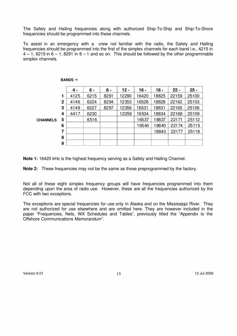
The Safety and Hailing frequencies along with authorized Ship-To-Ship and Ship-To-Shorefrequencies should be programmed into these channels.
To assist in an emergency with a crew not familiar with the radio, the Safety and Hailingfrequencies should be programmed into the first of the simplex channels for each band i.e., 4215 in
4 – 1, 6215 in 6 – 1, 8291 in 8 – 1 and so on. This should be followed by the other programmablesimplex channels.
BANDS
4 - 6 - 8 - 12 - 16 - 18 - 22 - 25 -
1 4125 6215 8291 12290 16420 18825 22159 25100
2 4146 6224 8294 12353 16528 18828 22162 25103
3 4149 6227 8297 12356 16531 18831 22165 25106
4 4417 6230 12359 16534 18834 22168 25109
CHANNELS 5 6516 16537 18837 22171 25112
6 16540 18840 22174 25115
7 18843 22177 25118
8
9
Note 1: 16420 kHz is the highest frequency serving as a Safety and Hailing Channel.
Note 2: These frequencies may not be the same as those preprogrammed by the factory.
Not all of these eight simplex frequency groups will have frequencies programmed into themdepending upon the area of radio use. However, these are all the frequencies authorized by theFCC with two exceptions.
The exceptions are special frequencies for use only in Alaska and on the Mississippi River. Theyare not authorized for use elsewhere and are omitted here. They are however included in thepaper “Frequencies, Nets, WX Schedules and Tables”, previously titled the “Appendix to theOffshore Communications Memorandum”.
Version 6.01 12 Jul 200615

8/6/2019 Com Using Icom m710 m710rt
http://slidepdf.com/reader/full/com-using-icom-m710-m710rt 17/25
8 Operating The Radio and The Display
With the radio on, go to the User Programmable Channels section by pressing 1 RX on thekeyboard or turning the Group Knob. Select any channel.
8.1 Frequency / Channel Presentation
As noted above, the display will present either:
- Numbers on the upper line with one decimal point followed on the bottom by some letterswith more numbers with two decimal points.
- Some numbers on the upper row with no decimal points followed by some letters andbelow that, a number or an alphanumeric (a word or a name given to that particularfrequency) such as BBC or 4 Charlie.
- All channels can be displayed either way by depressing the CH/FREQ button on thekeypad at the right. Nothing changes except what appears on the display.
8.2 The RX Icon
The RX symbol or icon appears on the left of the display indicating the radio is ready to RECEIVE.
8.3 Simplex, Duplex or Blank Display
Between the two rows, the words SIMP or DUP may appear or the line can be blank.
SIMP refers to SIMPLEX, meaning that transmit and receive frequencies are the same. Italso means that anyone listening to that frequency hears both sides of the conversation.
DUP refers to DUPLEX, meaning that transmit and receive frequencies are different.Anyone listening to that frequency can hear one side of the conversation only, affordingsome privacy.
A blank line indicates there is no transmit frequency for this channel. This is normal forbroadcast stations such as the Voice Of America and weather fax broadcast stations wheretransmitting on that frequency would create interference and is not looked at kindly by theauthorities - or by anyone else.
Version 6.01 12 Jul 200616
8/6/2019 Com Using Icom m710 m710rt
http://slidepdf.com/reader/full/com-using-icom-m710-m710rt 18/25
On the right of the display are two or three letters indicating the emission mode. For SSBoperations, it should be USB, Upper Sideband or J3E (the same) except when listening to acommercial radio broadcast station or WWV when the mode should be AM.
The DIMMER button for the LCD display is adjacent to the POWER button. The M710 radio hasonly two positions; on or off. However, contrast and brightness may also be controlled via “SETMODE” discussed on page 14 of the M710 Instruction Manual.
With the M710RT, depress the "Dimmer" button while rotating the Channel and Group Knobs (seepage 2 in the M710RT Manual).
9 The Buttons Under The Display
.9.1 The Mode Button (Emission Modes)
If the mode is anything other than USB (or J3E), depress the “MODE” button (just below the lowerleft corner of the display) as many times as it takes to change it back to USB. Then go to thekeyboard and depress CE and then RX to save it. You should hear a “beep” indicting it has beensaved.
Continued depressing the “MODE” button will change the display to AM, LSB, J2B, FSK, CW andthen back to USB.
USB or Upper Sideband is the type of emission or operating mode used for most marineSSB transmissions. FSK is used for some Weather Facsimiles (WX Fax), but USB workswell.
AM or Amplitude Modulation is the same type of transmission as you have on your homeAM radio. This is sometimes called DSB for Double Sideband and was the standardtransmission method in years gone by. It is no longer used except for some governmentoperations and commercial broadcast radio.
LSB or Lower Sideband is used for some foreign weather facsimile broadcasts and byHams at frequencies below 7.300 MHz. Ham operations at frequencies from 7.300 to30.000 MHz are USB.
AFSK or Audio Frequency Shift Keying is an emission technique used in advancedapplications involving accessories and is beyond the scope of this paper.
FSK or Frequency Shift Keying is another emission technique used in advancedapplications involving accessories and also beyond the scope of this paper.
CW or Continuous Wave is the type of emission used for Morse code. It is sometimescalled A1A.
Version 6.01 12 Jul 200617

8/6/2019 Com Using Icom m710 m710rt
http://slidepdf.com/reader/full/com-using-icom-m710-m710rt 19/25
The Emission Modes displayed on this radio maydiffer from the mode coding used by the FCC.Sometimes they are used interchangeably. Aconversion table follows to help clarify.
M - 710 / 710RTMODE EMISSION
AM H3E
CW A1AFSK F1B
ASFK J2ELSB J3E
R3E R3EUSB J3E
9.2 The Other Buttons
In addition to the MODE button, the remaining buttons under the display are AGC, NB, SQL andFUNC. TUNE is located between the knobs.
9.2.1 AGC or AUTOMATIC GAIN CONTROL - Normally ON AGC adjusts the receiver’s gain to ensure week signals are received at the same volume asstrong. If it is off, the letters AGC with lines through it will appear on the display. Depressthe AGC button to turn it on (no symbol or indication). Without AGC on, some signals maybe too loud.
With weak weather facsimile (WX Fax) signals however, some picture improvement may beachieved by turning the AGC off.
9.2.2 NB or NOISE BLANKER - Normally OFF NB is used to eliminate repetitive noise interference from equipment close by such asfluorescent lights, motors, NMEA Data stream for electronic equipment on board and thelike. It is on when the letters NB appear on the right side of the display.
9.2.3 SQL or Squelch - Normally OFF SQL eliminates the hiss heard on SSB, but it can also reduce sensitivity to weak signals.When it is on, the letters SQL appear on the right side of the display.
You won’t hurt anything by depressing these buttons, but it will help if you set them as suggestedabove. They are mainly to enhance how well you receive. NB on some other radios brands maycreate interference for neighboring vessels when transmitting.
Version 6.01 12 Jul 200618
8/6/2019 Com Using Icom m710 m710rt
http://slidepdf.com/reader/full/com-using-icom-m710-m710rt 20/25
9.2.4 FUNC or Function is something you could get into trouble with the first time aroundso leave it alone for now. Consult the ICOM Instruction Manual after you are comfortablewith the radio. To minimize “follow on” grief, write down all settings before changinganything in FUNC.
9.2.5 TUNE - The TUNE button activates the Automatic Tuner. Depressing the TUNEbutton peaks the antenna system to the transmit frequency. There is normally no need totune when receiving although it sometimes helps with weak signals. There is also no needto retune when making small TX frequency changes such from 4146.0 to 4149.0 kHz.
The AT-130 Automatic Tuner is standard with these radios and with it, the TUNE button canbe ignored. The AT-130 will automatically tune when the channel is changed or the sidemicrophone button is depressed to talk depending how the radio is setup.
Two tuning methods are available with the AT-130. With the first, the tuner will
automatically retune every time a channel is changed with the knobs. With the secondmethod, the tuner will automatically retune only when the microphone button is depressed.Microphone tuning is preferred because the antenna doesn’t usually need to be retuned tolisten.
Which one used is selected in the SET MODE (3) found on page 13 of the InstructionManual.
If another model or brand tuner is being used, the TUNE button must be depressed beforetransmitting if the frequency has been changed. When the TUNE button is depressed, theword TUNE will appear on the left side of the display.
10 The Keypad
The keypad at the right side of the radio has two functions. They are, direct channel selection andinputting new frequencies.
In addition to the CH/FREQ already discussed, note the Keypad buttons labeled CE, -, RX and TX.
10.1 CE or Change Entry is used mainly to change a frequency. When it is depressed, asmall triangle appears on the left of the display to indicate it is active and is accompaniedwith a beep. Depressing the CE button will also erase any erroneous entries.
10.2 The Dash Symbol “-” is used when direct dialing to the simplex channels associatedwith the duplex channel section of the memory such as 4-1, 12-3, etc.
Version 6.01 12 Jul 200619
8/6/2019 Com Using Icom m710 m710rt
http://slidepdf.com/reader/full/com-using-icom-m710-m710rt 21/25
10.3 RX or RECEIVE is used to change channels or enter a new receiving frequency. Tochange channels, simply key in the channel number followed by RX.
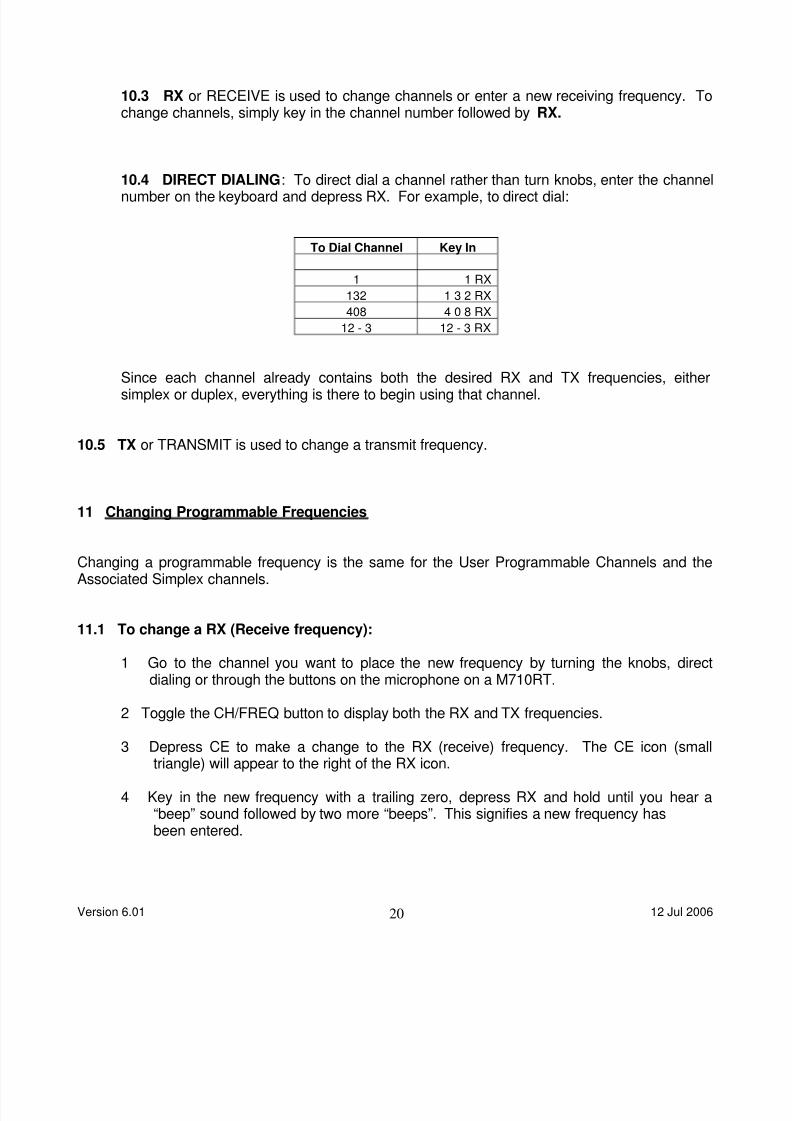
10.4 DIRECT DIALING: To direct dial a channel rather than turn knobs, enter the channelnumber on the keyboard and depress RX. For example, to direct dial:
To Dial Channel Key In
1 1 RX
132 1 3 2 RX
408 4 0 8 RX
12 - 3 12 - 3 RX
Since each channel already contains both the desired RX and TX frequencies, eithersimplex or duplex, everything is there to begin using that channel.
10.5 TX or TRANSMIT is used to change a transmit frequency.
11 Changing Programmable Frequencies
Changing a programmable frequency is the same for the User Programmable Channels and theAssociated Simplex channels.
11.1 To change a RX (Receive frequency):
1 Go to the channel you want to place the new frequency by turning the knobs, directdialing or through the buttons on the microphone on a M710RT.
2 Toggle the CH/FREQ button to display both the RX and TX frequencies.
3 Depress CE to make a change to the RX (receive) frequency. The CE icon (smalltriangle) will appear to the right of the RX icon.
4 Key in the new frequency with a trailing zero, depress RX and hold until you hear a“beep” sound followed by two more “beeps”. This signifies a new frequency hasbeen entered.
Version 6.01 12 Jul 200620

8/6/2019 Com Using Icom m710 m710rt
http://slidepdf.com/reader/full/com-using-icom-m710-m710rt 22/25
Concurrently, the CE symbol will disappear. The line between the two frequenciesmay also change depending on whether the RX and TX frequencies are now thesame or differ (Simplex or Duplex).
11.2 To change a TX (Transmit frequency):
1 Go to the channel you want to place the new frequency by turning the knobs, directdialing or by using the buttons on the microphone on a M710RT.
2 Toggle the CH/FREQ button to display both the RX and TX frequencies.
3 Depress the TX button – The flashing TX icon appears on the left of the display witha “beep”.
4 Depress the CE button - The CE symbol (small triangle) appears next to the flashing TXwith a beep.
5 Key in the new transmit frequency, remembering to add a trailing zero.
6 Depress the TX button and hold. You will hear three “beeps” and the CE symbol willdisappear. Depress the TX button again. You will hear another “beep” and the flashingTX will disappear. The new transmit frequency is now ready for use.
NOTE: You can’t just use any frequency you might want for Marine SSB. As noted before,frequencies and their use are specified under international agreements and controlled in the US bythe FCC. This includes US flagged vessels wherever they might be as well unless there is aconflict with the local authorities.
The FCC takes a dim view of independent frequency determination and they back this up withfines that can be stiff. Selecting something other than designated listed frequencies can and doescreate interference with other radio transmissions as well. There are plenty of authorizedfrequencies available for maritime use.
One final note on programming: With 160 programmable channels available on this radio and anadditional 72 simplex channels following the duplex channels, it is very it is easy to forget what iswhere. Placing a list of channels / frequencies in a loose-leaf binder or under a clear plastic sheeton the chart table helps. It facilitates knowing what channel to go to and in short order, becomesindispensable.
Cruiser Nets and their frequencies come and go, interests change, new Nets come on, the cruisingarea changes and so on. Putting your list of frequencies on a computer spread sheet may be a lotof work the first time, but it makes for easy change and good organization. With 160 channelsavailable, leaving a blank channel every now and then helps to accommodate the changes.
Version 6.01 12 Jul 200621

8/6/2019 Com Using Icom m710 m710rt
http://slidepdf.com/reader/full/com-using-icom-m710-m710rt 23/25
12 The M - 710RT Microphone
Unique to the M710RT transceiver is a microphone with controls to change the channels and toactivate a selected control such as squelch in addition to the usual Push-To-Talk button on theside for transmission. It is available only with the M710RT.
12.1 Channel Selection Buttons
Channel selection can be controlled from the microphone in the same way as the Channel Knobon the face of the radio. By pressing one of the two buttons with triangles, the channel can bechanged one step at a time. Holding the button down will rapidly sequence through the channels.
Operating the same as the Channel Knob, the microphone Channel Selector will remain withinwhatever memory sector it started out. For example, in the User Programmable Memory and atsome channel such as 146, depressing the “UP” button will run the channels up to 160 and thenrecycle starting at Channel 1. Doing the same at some duplex channel such as 403 will run theselection up to 427, then into the Associated Simplex Channels starting with 4 – 1, through them to4 – 9 and recycle back to duplex Channel 401. The reverse is true with the holding the downbutton.
12.2 P SWITCH
The little button on the face of the microphone labeled “P” is used in place of any one of thefunction buttons under the display. These control functions, MODE, AGC, NB, SQL and TUNE arediscussed above.
Only one function at a time can be controlled with the “P” switch although all can be activated.This is accomplished by holding down both the “P” switch and the desired function switch whileturning the radio on. The “P” button is then used to toggle the selected function on or off. If theMODE function is selected, the “P” switch will cycle through all the Emission Modes.
To deactivate the “P” switch, turn the radio off. Holding the “P” switch down, turn the radio back onwithout depressing any of the function buttons.
12.3 PUSH TO TALK BUTTON (PTT)
Version 6.01 12 Jul 200622

8/6/2019 Com Using Icom m710 m710rt
http://slidepdf.com/reader/full/com-using-icom-m710-m710rt 24/25
The button on the side of the microphone is used to transmit in the conventional way. Theoperation is one way; depressed to transmit and released to receive.
This button will also active the AT-130 antenna tuner to tune to a new frequency (if selected in theset-up) when a change has been made. It is near instantaneous and draws very little current.
13 Transmitting
To transmit, hold the mike an inch or two away from your mouth, depress the button and speak ina normal voice. Shouting or holding the mike too close to your mouth doesn’t help and can evenmake it difficult for you to be understood. Remember to depress the mike button before you startto speak and hold it down until you finish.
These radios work on the concept of either Receive or Transmit, one at a time, but not both at thesame time. They are not like a telephone. This means, you won’t be heard if you talk whilesomeone else is talking to you. And they won’t hear what you have to say either.
Remember to identify yourself with the name of the vessel and the Ship Radio Call Sign (top line -right on the Ship/Aircraft Radio Station License posted somewhere in the vicinity of the radio).
Version 6.01 12 Jul 200623

8/6/2019 Com Using Icom m710 m710rt
http://slidepdf.com/reader/full/com-using-icom-m710-m710rt 25/25