COLOUR REMOVAL FROM COAL BASED GAS PRODUCER EFFLUENT AFTER
12
International Journal of Engineering Research and Development e-ISSN: 2278-067X, p-ISSN: 2278-800X Volume 3, Issue 8 (September 2012), PP. 76-87 76 Colour Removal from Coal Gas Based Producer Effluent after Treatment through ETP Oindrila Gupta 1 , Rajarshi Kar 2 1,2 department of Chemical Engineering, Heritage Institute of Technology, Kolkata Abstract––The removal of dyes present in industrial effluent has received great attention in the past few years. This is partly due to increasing environmental awareness and the implementation of ever stricter environmental rules. Adsorption is one of the techniques used for the effective removal of dyes. However, the efficiency of the adsorption process depends on the choice of a suitable adsorbent. Because of the high cost of some conventional adsorbents, researches have been seeking alternatives, such as Neem tree leaves. The Neem tree (Azadirachta indica) is native to India and its importance has been recognized by the US National Academy of Sciences, which published a report in 1992 entitled “Neem – a tree for solving global problems”. Adsorption has been used successfully in the removal of color from effluents. Activated carbon is the most used adsorbent. Due to its high cost and considering the enormous quantity of effluent produced by textile industries use of alternative adsorbents, also called non-conventional low-cost adsorbents. An example of this group of adsorbents is the Neem tree leaf. The Neem tree (Azadirachta indica), of the family Meliaceae, is native to India and was adapted for its growth in Brazil a few years ago. The leaf has polar groups on the surface, which gives it a high cationic exchange capacity .The aim of this study is to investigate the efficiency of Neem tree leaves in the removal of dyes present in industrial effluents, as well as to verify the influence of different parameters on the color removal process. In the industry, the activities involving the tars generate problems due to the discharge of toxic effluents, originating from the byproducts generated. If not treated properly before being discharged into natural water bodies, the effluent from this industry may reach potable water resources, causing serious ecological concern. Therefore, the development of new technologies for the removal of color from industrial effluents has received a lot attention over the past few years, partly driven by an increasing environmental awareness and the implementation of ever stricter environmental rules (HOLME, 1984; MOTSCHI, 1994). Keywords––Adsorption, Azadirachta indica ,high cationic exchange capacity I. PROCESS OF TREATING PRODUCER GAS EFFLUENT Effluent from coal gas producing plant is collected into settling tanks . In bar screen chamber coarse material is removed and only acceptable size of particle will be transfer into oil & grease separation tank followed by collection tank available at site of 500 KL capacity. Figure 1: settling tank in Effluent Treatment Plant In oil& Grease separation tank mechanical belt oil skimmer is installed to remove free oil & grease form top of liquid. Effluent free from free oil & grease will be received into new underground collection tank through gravity. From underground collection tank effluent will transfer automatically with help of level sensor into equalization tank. 2 No. Equalization tank is fitted with coarse diffuser, which ensures proper mixing & homogenizes effluent along with primary precipitation of raw effluent. Lime, caustic, alum and other chemical is added here to make a complete batch of 50 KL. This system will act as fill, react & transfer basis.
Transcript of COLOUR REMOVAL FROM COAL BASED GAS PRODUCER EFFLUENT AFTER

International Journal of Engineering Research and Development e-ISSN: 2278-067X, p-ISSN: 2278-800X Volume 3, Issue 8 (September 2012), PP. 76-87
76
Colour Removal from Coal Gas Based Producer Effluent after
Treatment through ETP
Oindrila Gupta1, Rajarshi Kar
2
1,2department of Chemical Engineering, Heritage Institute of Technology, Kolkata
Abstract––The removal of dyes present in industrial effluent has received great attention in the past few years. This is
partly due to increasing environmental awareness and the implementation of ever stricter environmental rules.
Adsorption is one of the techniques used for the effective removal of dyes. However, the efficiency of the adsorption
process depends on the choice of a suitable adsorbent. Because of the high cost of some conventional adsorbents,
researches have been seeking alternatives, such as Neem tree leaves. The Neem tree (Azadirachta indica) is native to
India and its importance has been recognized by the US National Academy of Sciences, which published a report in 1992
entitled “Neem – a tree for solving global problems”. Adsorption has been used successfully in the removal of color from
effluents. Activated carbon is the most used adsorbent. Due to its high cost and considering the enormous quantity of
effluent produced by textile industries use of alternative adsorbents, also called non-conventional low-cost adsorbents. An
example of this group of adsorbents is the Neem tree leaf. The Neem tree (Azadirachta indica), of the family Meliaceae, is
native to India and was adapted for its growth in Brazil a few years ago. The leaf has polar groups on the surface, which
gives it a high cationic exchange capacity .The aim of this study is to investigate the efficiency of Neem tree leaves in the
removal of dyes present in industrial effluents, as well as to verify the influence of different parameters on the color
removal process. In the industry, the activities involving the tars generate problems due to the discharge of toxic effluents,
originating from the byproducts generated. If not treated properly before being discharged into natural water bodies, the
effluent from this industry may reach potable water resources, causing serious ecological concern. Therefore, the
development of new technologies for the removal of color from industrial effluents has received a lot attention over the
past few years, partly driven by an increasing environmental awareness and the implementation of ever stricter
environmental rules (HOLME, 1984; MOTSCHI, 1994).
Keywords––Adsorption, Azadirachta indica ,high cationic exchange capacity
I. PROCESS OF TREATING PRODUCER GAS EFFLUENT Effluent from coal gas producing plant is collected into settling tanks . In bar screen chamber coarse material is
removed and only acceptable size of particle will be transfer into oil & grease separation tank followed by collection tank
available at site of 500 KL capacity.
Figure 1: settling tank in Effluent Treatment Plant
In oil& Grease separation tank mechanical belt oil skimmer is installed to remove free oil & grease form top of
liquid. Effluent free from free oil & grease will be received into new underground collection tank through gravity. From
underground collection tank effluent will transfer automatically with help of level sensor into equalization tank. 2 No.
Equalization tank is fitted with coarse diffuser, which ensures proper mixing & homogenizes effluent along with primary
precipitation of raw effluent. Lime, caustic, alum and other chemical is added here to make a complete batch of 50 KL. This
system will act as fill, react & transfer basis.
Colour Removal from Coal Gas Based Producer Effluent after Treatment through ETP
77
Figure 2: equalization tank in Effluent Treatment Plant
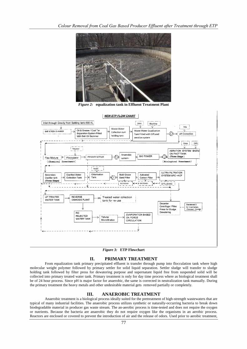
Figure 3: ETP Flowchart
II. PRIMARY TREATMENT From equalization tank primary precipitated effluent is transfer through pump into flocculation tank where high
molecular weight polymer followed by primary settler for solid liquid separation. Settler sludge will transfer to sludge
holding tank followed by filter press for dewatering purpose and supernatant liquid free from suspended solid will be
collected into primary treated water tank. Primary treatment is only for day time process where as biological treatment shall
be of 24 hour process. Since pH is major factor for anaerobic, the same is corrected in neutralization tank manually. During
the primary treatment the heavy metals and other undesirable material gets removed partially or completely.
III. ANAEROBIC TREATMENT Anaerobic treatment is a biological process ideally suited for the pretreatment of high-strength wastewaters that are
typical of many industrial facilities. The anaerobic process utilizes synthetic or naturally-occurring bacteria to break down
biodegradable material in producer gas waste stream. The an-aerobic process is time-tested and does not require the oxygen
or nutrients. Because the bacteria are anaerobic they do not require oxygen like the organisms in an aerobic process.
Reactors are enclosed or covered to prevent the introduction of air and the release of odors. Used prior to aerobic treatment,
Colour Removal from Coal Gas Based Producer Effluent after Treatment through ETP
78
an anaerobic system can be very effective and economical for removing high concentrations of BOD and COD prior to final
treatment by an aerobic process. Two stage anaerobic systems fitted with fixed media for increased surface area for better
BOD & COD reduction are provided in which 50-70% COD reduction takes place.
IV. BIO-TOWERS CUM PRE-AERATION TREATMENT A Bio-tower filter consists of a bed of highly permeable media on whose surface a mixed population of
microorganisms is developed as a slime layer. The word "filter" in this case is not correctly used for there is no straining or
filtering action involved. Passage of wastewater through the filter causes the development of a gelatinous coating of
bacteria, protozoa and other organisms on the media. With time, the thickness of the slime layer increases preventing
oxygen from penetrating the full depth of the slime layer. In the absence of oxygen, anaerobic decomposition becomes
active near the surface of the media. The continual increase in the thickness of the slime layer, the production of anaerobic
end products next to the media surface, and the maintenance of a hydraulic load to the filter, eventually causes sloughing of
the slime layer to start to form. This cycle is continuously repeated throughout the operation of a bio-filters filter. Outer
surface of media is always in contact of atmospheric air and work as striper. Spraying & biological striping of volatile
organic is carried out followed by partial degradation of BOD and COD. Further anaerobic treated effluent is pretreated and
made effluent acceptable for aeration system and to reduce chances of shock load on reduction of DO level in aeration tank.
V. SECONDARY TREATMENT First Stage aeration:
The first stage aeration unit is SAFF (submersed aeration fixed film type), where the biomass will partially grow
over the colony of biomass inside the tank. Target MLSS inside tank shall be 7000 -8000 mg/liter.
Tubular membrane diffusers are placed at the bottom of the aeration tank to provide air in the aeration tank.
From the aeration tank outlet the biologically treated Effluent along with some biomass will flow to the secondary clarifier
for biomass settling and clear aeration tank through V – notch if required. Excess sludge will be removing to aerobic
digester cum sludge holding tank for further treatment.
The secondary clarifier is of Conventional type with scraper for high efficiency clarification. We expect 80% reduction in
remaining BOD & COD.
Second Stage aeration:
The second stage aeration unit is extended aeration type, where the biomass will completed degrade organic matter
in the form of colony of biomass inside the tank. Target MLSS inside tank shall be 3000 -4000 mg/liter/
Tubular membrane diffusers are placed at the bottom of the aeration tank to provide air in the aeration tank.
From the aeration tank outlet the biologically treated Effluent along with some biomass will flow to the secondary clarifier
for biomass settling and clear water will flow through gravity to chlorination tank. Settled sludge will be re-circulated into
aeration tank through V – notch if required. Excess sludge will be removing to aerobic digester cum sludge holding tank for
further treatment.
The secondary clarifier is of Conventional type with scraper for high efficiency clarification. We expect 80% reduction in
remaining BOD & COD.
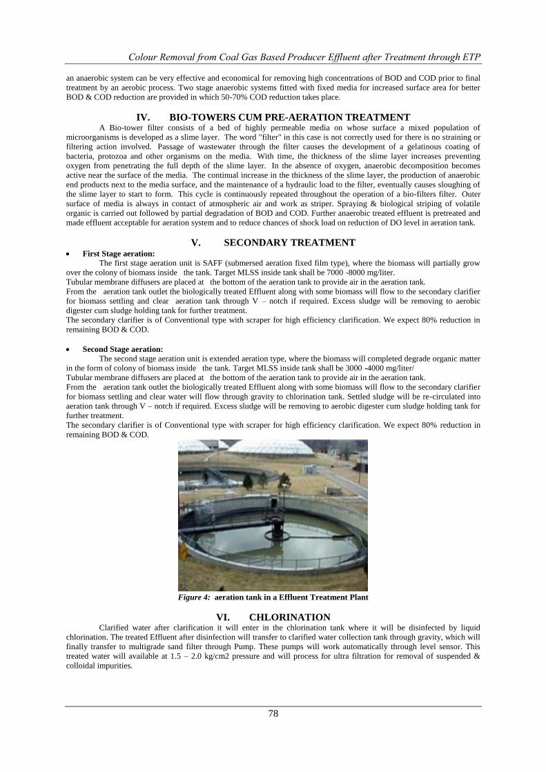
Figure 4: aeration tank in a Effluent Treatment Plant
VI. CHLORINATION Clarified water after clarification it will enter in the chlorination tank where it will be disinfected by liquid
chlorination. The treated Effluent after disinfection will transfer to clarified water collection tank through gravity, which will
finally transfer to multigrade sand filter through Pump. These pumps will work automatically through level sensor. This
treated water will available at 1.5 – 2.0 kg/cm2 pressure and will process for ultra filtration for removal of suspended &
colloidal impurities.
Colour Removal from Coal Gas Based Producer Effluent after Treatment through ETP
79
VII. SLUDGE The sludge from the secondary clarifier to be re-circulates into aeration tank if required. Extra sludge from
secondary and primary clarifier shall be removed from time to time into sludge holding tank for aerobic digestion prior to
dewatering through filter press. Filtrate will be transfer to equalization tank for further treatment.
VIII. ULTRA FILTRATION PROCESS Ultra filtration is a tangential flow, pressure driven filtration process that separates particles on the basis of their
molecular size. Pore diameters of ultra-filtration membranes are in the range of 10 to 200 A (0.001 to 0.02 micron). Solvents
and species having a diameter smaller than the pore size of the membrane will pass through the membrane and emerge as
ultra-filtrate known as permeate. Rejected species are progressively concentrated in the retained stream. Ultra filtration
membranes are reusable and cleanable with standard chemicals.
Ultra filtration of process water provides
Removal of virtually all-particulate matter, suspended solids, bacteria, viruses and pyrogenic species from
pharmaceutical and industrial process water.
Removal of colloidal material (non-reactive silica, iron, aluminum etc).
Removal of high molecular weight organic.
From MGF ETP treated water is automatically filtered with Ultra filtration for removal of high molecular organic
compound and removal of colloidal & suspended particle up to 0.01 micron. This will also reduce SDI (important parameter
for RO water inlet). After ultra-filtration resin column along with activated carbon is install to remove low molecular organic
compounds available in form of color etc.
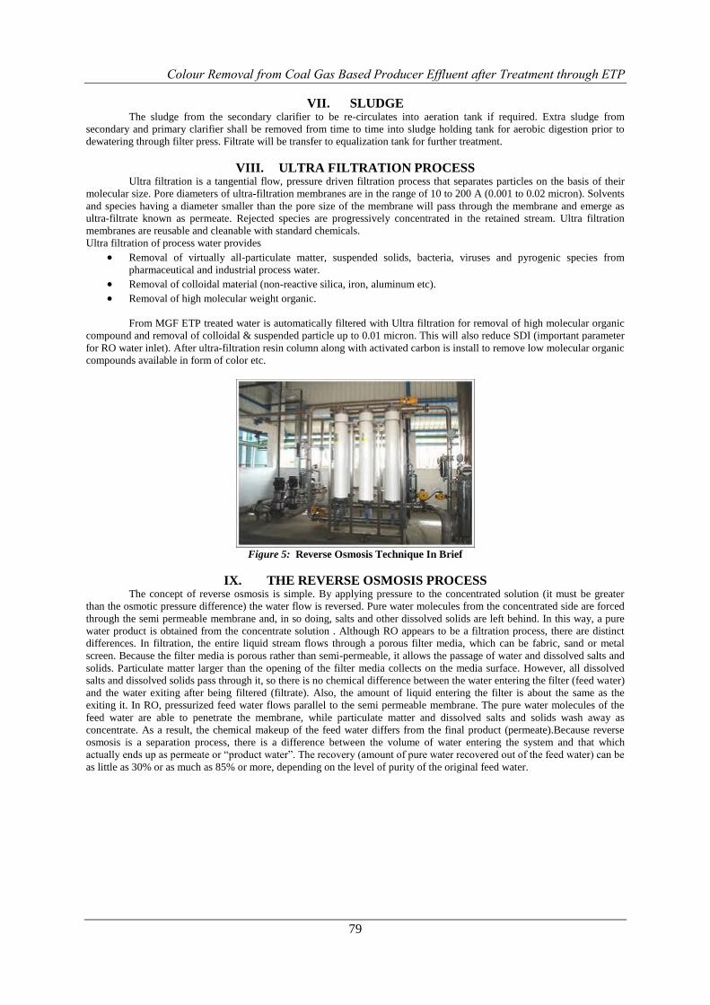
Figure 5: Reverse Osmosis Technique In Brief
IX. THE REVERSE OSMOSIS PROCESS The concept of reverse osmosis is simple. By applying pressure to the concentrated solution (it must be greater
than the osmotic pressure difference) the water flow is reversed. Pure water molecules from the concentrated side are forced
through the semi permeable membrane and, in so doing, salts and other dissolved solids are left behind. In this way, a pure
water product is obtained from the concentrate solution . Although RO appears to be a filtration process, there are distinct
differences. In filtration, the entire liquid stream flows through a porous filter media, which can be fabric, sand or metal
screen. Because the filter media is porous rather than semi-permeable, it allows the passage of water and dissolved salts and
solids. Particulate matter larger than the opening of the filter media collects on the media surface. However, all dissolved
salts and dissolved solids pass through it, so there is no chemical difference between the water entering the filter (feed water)
and the water exiting after being filtered (filtrate). Also, the amount of liquid entering the filter is about the same as the
exiting it. In RO, pressurized feed water flows parallel to the semi permeable membrane. The pure water molecules of the
feed water are able to penetrate the membrane, while particulate matter and dissolved salts and solids wash away as
concentrate. As a result, the chemical makeup of the feed water differs from the final product (permeate).Because reverse
osmosis is a separation process, there is a difference between the volume of water entering the system and that which
actually ends up as permeate or “product water”. The recovery (amount of pure water recovered out of the feed water) can be
as little as 30% or as much as 85% or more, depending on the level of purity of the original feed water.
Colour Removal from Coal Gas Based Producer Effluent after Treatment through ETP
80
s
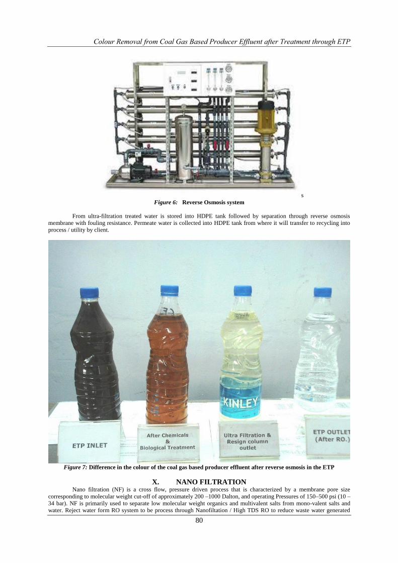
Figure 6: Reverse Osmosis system
From ultra-filtration treated water is stored into HDPE tank followed by separation through reverse osmosis
membrane with fouling resistance. Permeate water is collected into HDPE tank from where it will transfer to recycling into
process / utility by client.
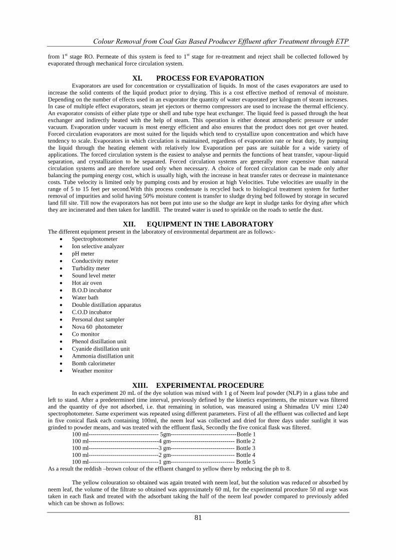
Figure 7: Difference in the colour of the coal gas based producer effluent after reverse osmosis in the ETP
X. NANO FILTRATION Nano filtration (NF) is a cross flow, pressure driven process that is characterized by a membrane pore size
corresponding to molecular weight cut-off of approximately 200 –1000 Dalton, and operating Pressures of 150–500 psi (10 –
34 bar). NF is primarily used to separate low molecular weight organics and multivalent salts from mono-valent salts and
water. Reject water form RO system to be process through Nanofiltation / High TDS RO to reduce waste water generated
Colour Removal from Coal Gas Based Producer Effluent after Treatment through ETP
81
from 1st stage RO. Permeate of this system is feed to 1st stage for re-treatment and reject shall be collected followed by
evaporated through mechanical force circulation system.
XI. PROCESS FOR EVAPORATION Evaporators are used for concentration or crystallization of liquids. In most of the cases evaporators are used to
increase the solid contents of the liquid product prior to drying. This is a cost effective method of removal of moisture.
Depending on the number of effects used in an evaporator the quantity of water evaporated per kilogram of steam increases.
In case of multiple effect evaporators, steam jet ejectors or thermo compressors are used to increase the thermal efficiency.
An evaporator consists of either plate type or shell and tube type heat exchanger. The liquid feed is passed through the heat
exchanger and indirectly heated with the help of steam. This operation is either doneat atmospheric pressure or under
vacuum. Evaporation under vacuum is most energy efficient and also ensures that the product does not get over heated.
Forced circulation evaporators are most suited for the liquids which tend to crystallize upon concentration and which have
tendency to scale. Evaporators in which circulation is maintained, regardless of evaporation rate or heat duty, by pumping
the liquid through the heating element with relatively low Evaporation per pass are suitable for a wide variety of
applications. The forced circulation system is the easiest to analyse and permits the functions of heat transfer, vapour-liquid
separation, and crystallization to be separated. Forced circulation systems are generally more expensive than natural
circulation systems and are therefore used only when necessary. A choice of forced circulation can be made only after
balancing the pumping energy cost, which is usually high, with the increase in heat transfer rates or decrease in maintenance
costs. Tube velocity is limited only by pumping costs and by erosion at high Velocities. Tube velocities are usually in the
range of 5 to 15 feet per second.With this process condensate is recycled back to biological treatment system for further
removal of impurities and solid having 50% moisture content is transfer to sludge drying bed followed by storage in secured
land fill site. Till now the evaporators has not been put into use so the sludge are kept in sludge tanks for drying after which
they are incinerated and then taken for landfill. The treated water is used to sprinkle on the roads to settle the dust.
XII. EQUIPMENT IN THE LABORATORY The different equipment present in the laboratory of environmental department are as follows:-
Spectrophotometer
Ion selective analyzer
pH meter
Conductivity meter
Turbidity meter
Sound level meter
Hot air oven
B.O.D incubator
Water bath
Double distillation apparatus
C.O.D incubator
Personal dust sampler
Nova 60 photometer
Co monitor
Phenol distillation unit
Cyanide distillation unit
Ammonia distillation unit
Bomb calorimeter
Weather monitor
XIII. EXPERIMENTAL PROCEDURE In each experiment 20 mL of the dye solution was mixed with 1 g of Neem leaf powder (NLP) in a glass tube and
left to stand. After a predetermined time interval, previously defined by the kinetics experiments, the mixture was filtered
and the quantity of dye not adsorbed, i.e. that remaining in solution, was measured using a Shimadzu UV mini 1240
spectrophotometer. Same experiment was repeated using different parameters. First of all the effluent was collected and kept
in five conical flask each containing 100ml, the neem leaf was collected and dried for three days under sunlight it was
grinded to powder means, and was treated with the effluent flask, Secondly the five conical flask was filtered.
100 ml----------------------------------- 5gm---------------------------------Bottle 1
100 ml-----------------------------------4 gm-------------------------------- Bottle 2
100 ml-----------------------------------3 gm-------------------------------- Bottle 3
100 ml-----------------------------------2 gm-------------------------------- Bottle 4
100 ml-----------------------------------1 gm-------------------------------- Bottle 5
As a result the reddish –brown colour of the effluent changed to yellow there by reducing the ph to 8.
The yellow colouration so obtained was again treated with neem leaf, but the solution was reduced or absorbed by
neem leaf, the volume of the filtrate so obtained was approximately 60 ml, for the experimental procedure 50 ml avge was
taken in each flask and treated with the adsorbant taking the half of the neem leaf powder compared to previously added
which can be shown as follows:

Colour Removal from Coal Gas Based Producer Effluent after Treatment through ETP
82
50 ml-------------------------------------2.5 gm------------------------------ Bottle 1
50 ml-------------------------------------2.0 gm------------------------------ Bottle 2
50 ml-------------------------------------1.5 gm-------------------------------Bottle 3
50 ml-----------------------------------------1.0 gm---------------------------Bottle 4
50 ml-------------------------------------0.5 gm------------------------------- Bottle 5
The solution was again filtered and the filtrate so obtained was individually tested as given below:-
FILTRATE + BLEACHING POWDER + WATER
--------------------------------→COLOURLESS LIQUID
The adsorption experiments were carried out and plotted according to Langmuir isotherm equation .The effluent
was collected and kept in five conical flask each containing 100ml, the neem leaf was collected and dried for three days
under sunlight it was grinded to powder means, and was treated with the effluent flask.
Figure 8: AFTER TREATMENT OF NLP TO THE EFFLUENT(GREEN)
In each experiment 20 mL of the dye solution was mixed with 1 g of Neem leaf powder (NLP) in a conical flask
and left to stand for 24 hours predetermined time interval, the mixture was filtered and the filtrate (reduced volume) so
obtained was again treated with Neem Leaf Powder (NLP) and left to get adsorbed for another 24 hours. After two-three
repetition of the same process the resulting filtrate so obtained was yellow in color that is the reddish brown color had
changed to yellow, the filtrates were analyzed and treated with reagents which includes the following:-
1. Bleaching powder
2. Water
3. Little bit of 0.1M NaOH
The filtrate so obtained was treated with bleaching powder and a little of water as a result of which the solution
became more and more denser, the dense sample so obtained was filtered and the solid particle or the residue or the
precipitate was taken out ,the filtrate was analyzed and it was found to have a colorless or a clear liquid .
Colour Removal from Coal Gas Based Producer Effluent after Treatment through ETP
83
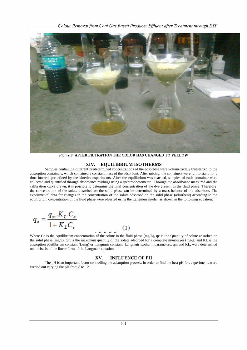
Figure 9: AFTER FILTRATION THE COLOR HAS CHANGED TO YELLOW
XIV. EQUILIBRIUM ISOTHERMS Samples containing different predetermined concentrations of the adsorbate were volumetrically transferred to the
adsorption containers, which contained a constant mass of the adsorbent. After mixing, the containers were left to stand for a
time interval predefined by the kinetics experiments. After the equilibrium was reached, samples of each container were
collected and quantified through absorbance readings using a spectrophotometer. Through the absorbance measured and the
calibration curve drawn, it is possible to determine the final concentration of the dye present in the fluid phase. Therefore,
the concentration of the solute adsorbed on the solid phase can be determined by a mass balance of the adsorbate. The
experimental data for changes in the concentration of the solute adsorbed on the solid phase (adsorbent) according to the
equilibrium concentration of the fluid phase were adjusted using the Langmuir model, as shown in the following equation:
……………….
Where Ce is the equilibrium concentration of the solute in the fluid phase (mg/L), qe is the Quantity of solute adsorbed on
the solid phase (mg/g), qm is the maximum quantity of the solute adsorbed for a complete monolayer (mg/g) and KL is the
adsorption equilibrium constant (L/mg) or Langmuir constant. Langmuir isotherm parameters, qm and KL, were determined
on the basis of the linear form of the Langmuir equation.
XV. INFLUENCE OF PH The pH is an important factor controlling the adsorption process. In order to find the best pH for, experiments were
carried out varying the pH from 8 to 12.

Colour Removal from Coal Gas Based Producer Effluent after Treatment through ETP
84
GRAPH :1
Table 1: Langmuir Isotherms For Different Ph Values
The influence of pH on the adsorption equilibrium can be observed in Figure 1. It is possible to verify that the pH
of the medium influences strongly the adsorption process.
Table 2: Influence of Agitation
In order to optimize the adsorption phenomenon, the influence of agitation was studied. Some samples of the
concentrated solutions of the studied dye were kept under constant agitation and other were left to stand. Through the results
obtained from several experiments carried out with different concentrations of the solution, but the same adsorbent mass, it
was possible to draw Langmuir adsorption isotherms, as shown in Figure 2. The Langmuir parameters are given in Table
Langmuir isotherm parameters for experiments with and without agitation On analyzing the Langmuir isotherm parameters
given in Table 2, as well as in Figure 2, it can be verified that the qm (maximum adsorption capacity) values for the two
cases are close, and as the utilization of the process without agitation allows an energy saving, the subsequent experiments
were carried out without agitation.
Colour Removal from Coal Gas Based Producer Effluent after Treatment through ETP
85
GRAPH: 2
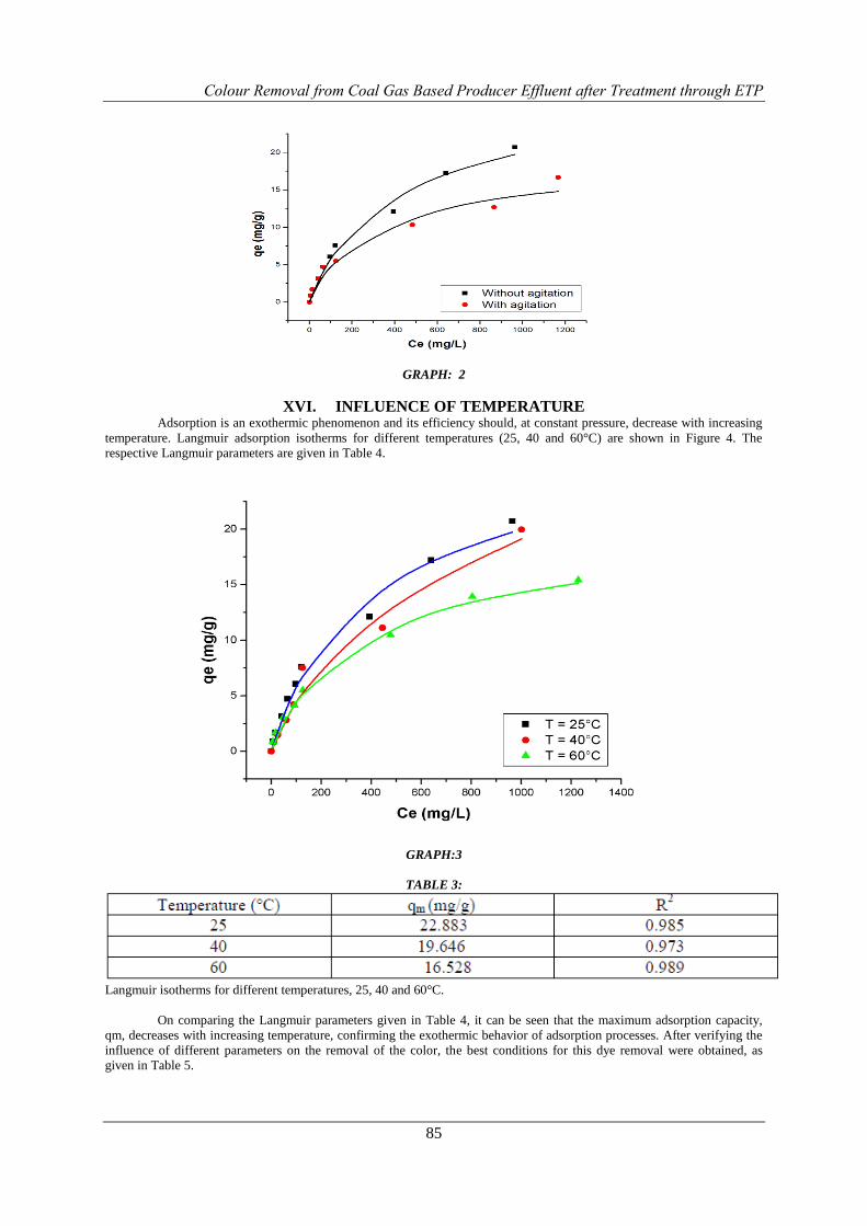
XVI. INFLUENCE OF TEMPERATURE Adsorption is an exothermic phenomenon and its efficiency should, at constant pressure, decrease with increasing
temperature. Langmuir adsorption isotherms for different temperatures (25, 40 and 60°C) are shown in Figure 4. The
respective Langmuir parameters are given in Table 4.
GRAPH:3
TABLE 3:
Langmuir isotherms for different temperatures, 25, 40 and 60°C.
On comparing the Langmuir parameters given in Table 4, it can be seen that the maximum adsorption capacity,
qm, decreases with increasing temperature, confirming the exothermic behavior of adsorption processes. After verifying the
influence of different parameters on the removal of the color, the best conditions for this dye removal were obtained, as
given in Table 5.
Colour Removal from Coal Gas Based Producer Effluent after Treatment through ETP
86
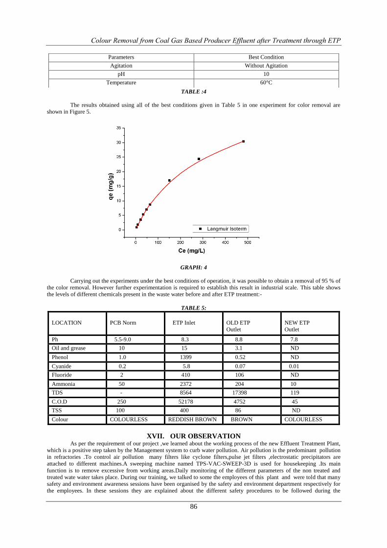
TABLE :4
The results obtained using all of the best conditions given in Table 5 in one experiment for color removal are
shown in Figure 5.
GRAPH: 4
Carrying out the experiments under the best conditions of operation, it was possible to obtain a removal of 95 % of
the color removal. However further experimentation is required to establish this result in industrial scale. This table shows
the levels of different chemicals present in the waste water before and after ETP treatment:-
TABLE 5:
LOCATION
PCB Norm
ETP Inlet
OLD ETP
Outlet
NEW ETP
Outlet
Ph 5.5-9.0 8.3 8.8 7.8
Oil and grease 10 15 3.1 ND
Phenol 1.0 1399 0.52 ND
Cyanide 0.2 5.8 0.07 0.01
Fluoride 2 410 106 ND
Ammonia 50 2372 204 10
TDS - 8564 17398 119
C.O.D 250 52178 4752 45
TSS 100 400 86 ND
Colour COLOURLESS REDDISH BROWN BROWN COLOURLESS
XVII. OUR OBSERVATION As per the requirement of our project ,we learned about the working process of the new Effluent Treatment Plant,
which is a positive step taken by the Management system to curb water pollution. Air pollution is the predominant pollution
in refractories .To control air pollution many filters like cyclone filters,pulse jet filters ,electrostatic precipitators are
attached to different machines.A sweeping machine named TPS-VAC-SWEEP-3D is used for housekeeping .Its main
function is to remove excessive from working areas.Daily monitoring of the different parameters of the non treated and
treated wate water takes place. During our training, we talked to some the employees of this plant and were told that many
safety and environment awareness sessions have been organised by the safety and environment department respectively for
the employees. In these sessions they are explained about the different safety procedures to be followed during the
Parameters Best Condition
Agitation Without Agitation
pH 10
Temperature 60°C
Colour Removal from Coal Gas Based Producer Effluent after Treatment through ETP
87
operations. They are also told about the health hazards and the preventive measures to be taken. They are made aware about
the importance of conserving energy and water and their role in keeping the environment clean and green.
XVIII. CONCLUSIONS A study was carried out to investigate dye removal from aqueous effluents, through adsorption processes using
NLP as the adsorbent. For color removal, the influence of different parameters, such as aqueous solution pH, bath agitation,
salt addition and temperature, was verified.
The equilibrium isotherms indicate that a basic medium favors the dye adsorption, and pH 8 showed a better
efficiency in the adsorption process. No significant difference was found between systems with and without agitation in
terms of color removal and, thus, systems without agitation were used with the aim of achieving a more economic process.
The addition of bleaching powder gave a significant result.
On the basis of the results obtained, it is possible to observe that the use of NLP as an adsorbent showed good
efficiency in the removal of the industrial dye studied. Thus, the use of NLP as an adsorbent could be applied as one of the
stages in textile effluent treatment processes.
REFERENCES [1]. DOHAREY, K. L.; SINGH, R. P. Evaluation of Neem (Azadirachta indica A. Juss) seed kernel extracts against
chafer beetles. Indian Journal of Entomology. v. 51, p. 217-220, 1989.
[2]. GUARATINI, C. C. I.; ZANONI, M. V. B. Corantes Têxteis. Revista Química Nova, São Paulo, v. 23, p. 71-78,
1999.
[3]. HOLME, J. Developments in the Chemistry and Technology of Organic Dyes. J. Griffiths Ed., Blackwell Scent.
Publ., Oxford, 1984.
[4]. KIMURA, I. Y. et al. Efeito do pH e do tempo de contato na adsorção de corantes reativos por microesferas de
quitosana. Polímeros: Ciência e Tecnologia. v. 9, n. 3, p. 51-57, jul/set 1999
[5]. MOTSCHI, H.; Chemical Safety. M. Richardson Ed.; V. C. H. Publ., 1994. 329 p.
[6]. PARROTA, J. A.; CHATURVEDI, A. N. Azadirachta indica A. Juss. Neem, margosa.
[7]. SO-ITF-SM-70. New Orleans, LA: U.S. Department of Agriculture, Forest Service, Southern Refractories
Manufacturing NESHAP: Industry Profile, Methodology, and Economic Impact Analysis (Draft Report) by Lisa
Conner, U.S. Environmental Protection Agency
[8]. Profiles of Tools and Tactics for Environmental Mainstreaming ENVIRONMENTAL MANAGEMENT
SYSTEMS (EMS) www.environmental-mainstreaming.org)
[9]. General Environmental Management Systems Awareness Training U.S. Department of the Interior, Office of
Environmental Policy and Compliance, Washington, D.C. August 2007
[10]. ENVIRONMENTAL AWARENESS ENVIRONMENTAL MANAGEMENT SYSTEM(E.M.S.)
[11]. A Brief History of Environmental Management Systems
[12]. Designing, developing and implementing a Management System: An Overview April 2010 by IBM corporate and
environment safety.