Color Strip Rev02 Um
19
CHAUVET, 3000 N 29 th Ct, Hollywood, FL 33020 U.S.A (800) 762-1084 – (954) 929-1115 FAX (954) 929-5560 www.chauvetlighting.com 2010-01-26/14:45 COLORstrip ™ USER MANUAL Snapshot OK on Dimmer Outdoor OK Sound Activated DMX512 Master/Slave 115V/230V Switch Replaceable Fuse User Serviceable Duty Cycle
Transcript of Color Strip Rev02 Um
8/7/2019 Color Strip Rev02 Um
http://slidepdf.com/reader/full/color-strip-rev02-um 1/19
CHAUVET, 3000 N 29
thCt, Hollywood, FL 33020 U.S.A
(800) 762-1084 – (954) 929-1115FAX (954) 929-5560
www.chauvetlighting.com2010-01-26/14:45
COLORstrip™
USER MANUAL
SnapshotOK on Dimmer
Outdoor OK
Sound ActivatedDMX512
Master/Slave
115V/230VSwitch
ReplaceableFuse
User Serviceable
Duty Cycle
8/7/2019 Color Strip Rev02 Um
http://slidepdf.com/reader/full/color-strip-rev02-um 2/19
COLORstrip™ User Manual 2 2010-01-26/14:45
TABLE OF CONTENTS COLORSTRIP™............................................................................................................................................. 1
1. BEFORE YOU BEGIN ................................................................................................................................ 3
WHAT IS INCLUDED......................................................................................................................................... 3UNPACKING INSTRUCTIONS ............................................................................................................................. 3AC POWER ................................................................................................................................................... 3CONTACT US................................................................................................................................................. 3SAFETY INSTRUCTIONS ................................................................................................................................... 4
2. INTRODUCTION ........................................................................................................................................ 5
FEATURES..................................................................................................................................................... 5DMX CHANNEL SUMMARY.............................................................................................................................. 5PRODUCT OVERVIEW ..................................................................................................................................... 6
3. SETUP ........................................................................................................................................................ 7
FUSE REPLACEMENT ...................................................................................................................................... 7FIXTURE LINKING ........................................................................................................................................... 7
Data Cabling ........................................................................................................................................... 7
DMX Data Cable ............................................................................................................................... 8Cable Connectors ............................................................................................................................. 83-Pin to 5-Pin Conversion Chart ....................................................................................................... 8
SETTING UP A DMX SERIAL DATA LINK ............................................................................................................ 9MASTER /SLAVE FIXTURE LINKING.................................................................................................................... 9MOUNTING .................................................................................................................................................... 9
Orientation ........................................................................................................................................ 9Rigging ............................................................................................................................................. 9
4. OPERATING INSTRUCTIONS ..................................................................................................................10
USING THE CONTROL PANEL ...........................................................................................................................10Control Panel Modes & Functions ..........................................................................................................10
MASTER /SLAVE & STAND ALONE....................................................................................................................11MASTER /SLAVE & STAND ALONE....................................................................................................................11
Built in programs detailed .......................................................................................................................11DMX CONTROL MODE ..................................................................................................................................12
Daisy Chain Connection ..................................................................................................................12DMX mode setup .............................................................................................................................12About DMX addressing ....................................................................................................................13
CONTROLLING MULTIPLE COLORSTRIPS™ AS ONE DEVICE ..............................................................................13DMX CHANNEL VALUES ................................................................................................................................15GENERAL TROUBLESHOOTING........................................................................................................................16TECHNICAL SUPPORT....................................................................................................................................17
5. APPENDIX .................................................................................................................................................17
DMX PRIMER...............................................................................................................................................17GENERAL MAINTENANCE ...............................................................................................................................18RETURNS PROCEDURE ..................................................................................................................................18CLAIMS ........................................................................................................................................................18
TECHNICAL SPECIFICATIONS ..........................................................................................................................19

8/7/2019 Color Strip Rev02 Um
http://slidepdf.com/reader/full/color-strip-rev02-um 3/19
COLORstrip™ User Manual 3 2010-01-26/14:45
Figure 1 - AC Voltage Switch
Not all fixtures have a voltageselect switch. Please be sure to
connect to the proper voltage.
1. BEFORE YOU BEGIN What is included
1 x COLORstrip™ 2 Tall Mounting Brackets 2 Short Mounting Brackets Power Cord Warranty Card User Manual
Unpacking Instructions
Immediately upon receiving a fixture, carefully unpack the carton, check the contents to ensure that
all parts are present, and have been received in good condition. Notify the shipper immediately and
retain packing material for inspection if any parts appear damaged from shipping or the carton itself
shows signs of mishandling. Save the carton and all packing materials. In the event that a fixture
must be returned to the factory, it is important that the fixture be returned in the original factory box
and packing.
AC Power
This fixture has an auto-switching power supply that can accommodate a wide range of inputvoltages. The only thing necessary to do before powering on the unit is to make sure the line voltageyou are applying is within the range of accepted voltages. This fixture will accommodate between100V and 240V AC. All fixtures must be powered directly off a switched circuit and cannot be run off arheostat (variable resistor) or dimmer circuit, even if the rheostat or dimmer channel is used solely fora 0% to 100% switch.
To determine the power requirements for a particular fixture, see the label affixed to the back plate ofthe fixture or refer to the fixture’s specifications chart. A fixture’s listed current rating is its averagecurrent draw under normal conditions. All fixtures must be powered directly off a switched circuit andcannot be run off a rheostat (variable resistor) or dimmer circuit, even if the rheostat or dimmerchannel is used solely for a 0% to 100% switch. Before applying power to a fixture, check that thesource voltage matches the fixture’s requirement. Check the fixture or device carefully to make surethat if a voltage selection switch exists that it is set to the correct linevoltage you will use.
Warning! Verify that the voltage select switch on your unit matches the line voltage applied. Damage to your fixture may result if the line voltage applied does not match the voltage indicated on the voltage selector switch. All fixtures must be connected to circuits with a suitable Earth Ground.
Contact Us
General Information Chauvet Lighting
3000 North 29th
Court
Hollywood, FL 33020
voice: 954.929.1115
fax: 954.929.5560
toll free: 800.762.1084
Technical Support Chauvet Lighting
3000 North 29th
Court
Hollywood, FL 33020
voice: 954.929.1115 (Press 4)
fax: 954.929.5560 (Attention: Service)
World Wide Web www.chauvetlighting.com
8/7/2019 Color Strip Rev02 Um
http://slidepdf.com/reader/full/color-strip-rev02-um 4/19
COLORstrip™ User Manual 4 2010-01-26/14:45
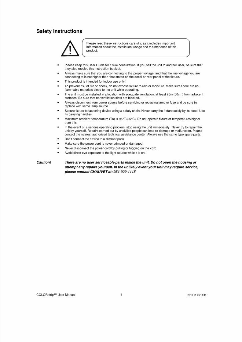
Safety Instructions
Please keep this User Guide for future consultation. If you sell the unit to another user, be sure thatthey also receive this instruction booklet.
Always make sure that you are connecting to the proper voltage, and that the line voltage you areconnecting to is not higher than that stated on the decal or rear panel of the fixture.
This product is intended for indoor use only!
To prevent risk of fire or shock, do not expose fixture to rain or moisture. Make sure there are noflammable materials close to the unit while operating.
The unit must be installed in a location with adequate ventilation, at least 20in (50cm) from adjacentsurfaces. Be sure that no ventilation slots are blocked.
Always disconnect from power source before servicing or replacing lamp or fuse and be sure toreplace with same lamp source.
Secure fixture to fastening device using a safety chain. Never carry the fixture solely by its head. Useits carrying handles.
Maximum ambient temperature (Ta) is 95°F (35°C). Do not operate fixture at temperatures higherthan this.
In the event of a serious operating problem, stop using the unit immediately. Never try to repair theunit by yourself. Repairs carried out by unskilled people can lead to damage or malfunction. Pleasecontact the nearest authorized technical assistance center. Always use the same type spare parts.
Don’t connect the device to a dimmer pack.
Make sure the power cord is never crimped or damaged.
Never disconnect the power cord by pulling or tugging on the cord.
Avoid direct eye exposure to the light source while it is on.
Caution! There are no user serviceable parts inside the unit. Do not open the housing or
attempt any repairs yourself. In the unlikely event your unit may require service,
please contact CHAUVET at: 954-929-1115.
Please read these instructions carefully, as it includes importantinformation about the installation, usage and maintenance of thisproduct.
8/7/2019 Color Strip Rev02 Um
http://slidepdf.com/reader/full/color-strip-rev02-um 5/19
COLORstrip™ User Manual 5 2010-01-26/14:45
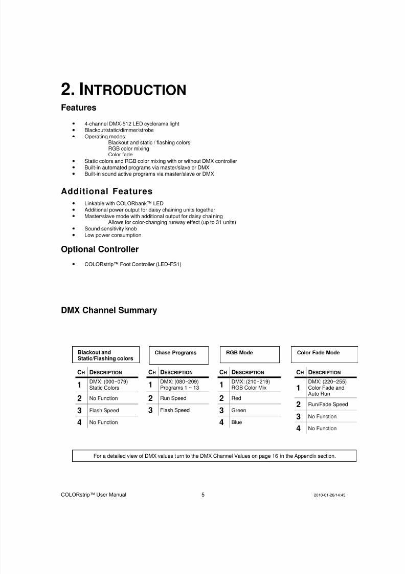
Blackout andStatic/Flashing colors
Chase Programs RGB Mode Color Fade Mode
For a detailed view of DMX values turn to the DMX Channel Values on page 16 in the Appendix section.
2. INTRODUCTION Features
4-channel DMX-512 LED cyclorama lightBlackout/static/dimmer/strobe
Operating modes:Blackout and static / flashing colorsRGB color mixingColor fade
Static colors and RGB color mixing with or without DMX controller
Built-in automated programs via master/slave or DMXBuilt-in sound active programs via master/slave or DMX
Additional Features
Linkable with COLORbank™ LED
Additional power output for daisy chaining units together
Master/slave mode with additional output for daisy chainingAllows for color-changing runway effect (up to 31 units)
Sound sensitivity knob
Low power consumption
Optional Controller
COLORstrip™ Foot Controller (LED-FS1)
DMX Channel Summary
CH DESCRIPTION
1DMX: (080~209)Programs 1 ~ 13
2Run Speed
3 Flash Speed
CH DESCRIPTION
1DMX: (000~079)Static Colors
2No Function
3 Flash Speed
4 No Function
CH DESCRIPTION
1DMX: (210~219)RGB Color Mix
2Red
3 Green
4 Blue
CH DESCRIPTION
1DMX: (220~255)Color Fade andAuto Run
2 Run/Fade Speed
3 No Function
4 No Function

8/7/2019 Color Strip Rev02 Um
http://slidepdf.com/reader/full/color-strip-rev02-um 6/19
COLORstrip™ User Manual 6 2010-01-26/14:45
Product Overview
Control Panel (rear)See exploded viewbelow
LEDs
Mounting Brackets
Power Output(For COLORstriponly, max 20)
IEC PowerConnector withFuse Holder
DMX In
DMX Out
Footcontroller Input(Optional Accessory LED-FS1)
SoundSensitivityAdjustment
Microphone
Master/Output
Control Panel
8/7/2019 Color Strip Rev02 Um
http://slidepdf.com/reader/full/color-strip-rev02-um 7/19
COLORstrip™ User Manual 7 2010-01-26/14:45
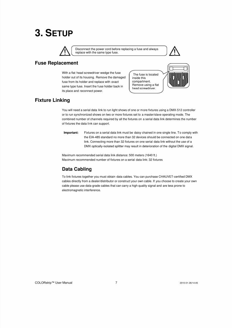
The fuse is locatedinside thiscompartment.Remove using a flathead screwdriver.
3. SETUP
Fuse Replacement
With a flat head screwdriver wedge the fuse
holder out of its housing. Remove the damaged
fuse from its holder and replace with exact
same type fuse. Insert the fuse holder back in
its place and reconnect power.
Fixture Linking
You will need a serial data link to run light shows of one or more fixtures using a DMX-512 controller
or to run synchronized shows on two or more fixtures set to a master/slave operating mode. Thecombined number of channels required by all the fixtures on a serial data link determines the number
of fixtures the data link can support.
Important: Fixtures on a serial data link must be daisy chained in one single line. To comply with
the EIA-485 standard no more than 32 devices should be connected on one data
link. Connecting more than 32 fixtures on one serial data link without the use of a
DMX optically-isolated splitter may result in deterioration of the digital DMX signal.
Maximum recommended serial data link distance: 500 meters (1640 ft.)
Maximum recommended number of fixtures on a serial data link: 32 fixtures
Data Cabling
To link fixtures together you must obtain data cables. You can purchase CHAUVET-certified DMX
cables directly from a dealer/distributor or construct your own cable. If you choose to create your own
cable please use data-grade cables that can carry a high quality signal and are less prone to
electromagnetic interference.
Disconnect the power cord before replacing a fuse and alwaysreplace with the same type fuse.
8/7/2019 Color Strip Rev02 Um
http://slidepdf.com/reader/full/color-strip-rev02-um 8/19
COLORstrip™ User Manual 8 2010-01-26/14:45
DMX DATA CABLE
Use a Belden© 9841 or equivalent cable which meets the specifications for EIA RS-485 applications.
Standard microphone cables cannot transmit DMX data reliably over long distances. The cable will
have the following characteristics:
2-conductor twisted pair plus a shield Maximum capacitance between conductors – 30 pF/ft.Maximum capacitance between conductor and shield – 55 pF/ft.Maximum resistance of 20 ohms / 1000 ft.Nominal impedance 100 – 140 ohms
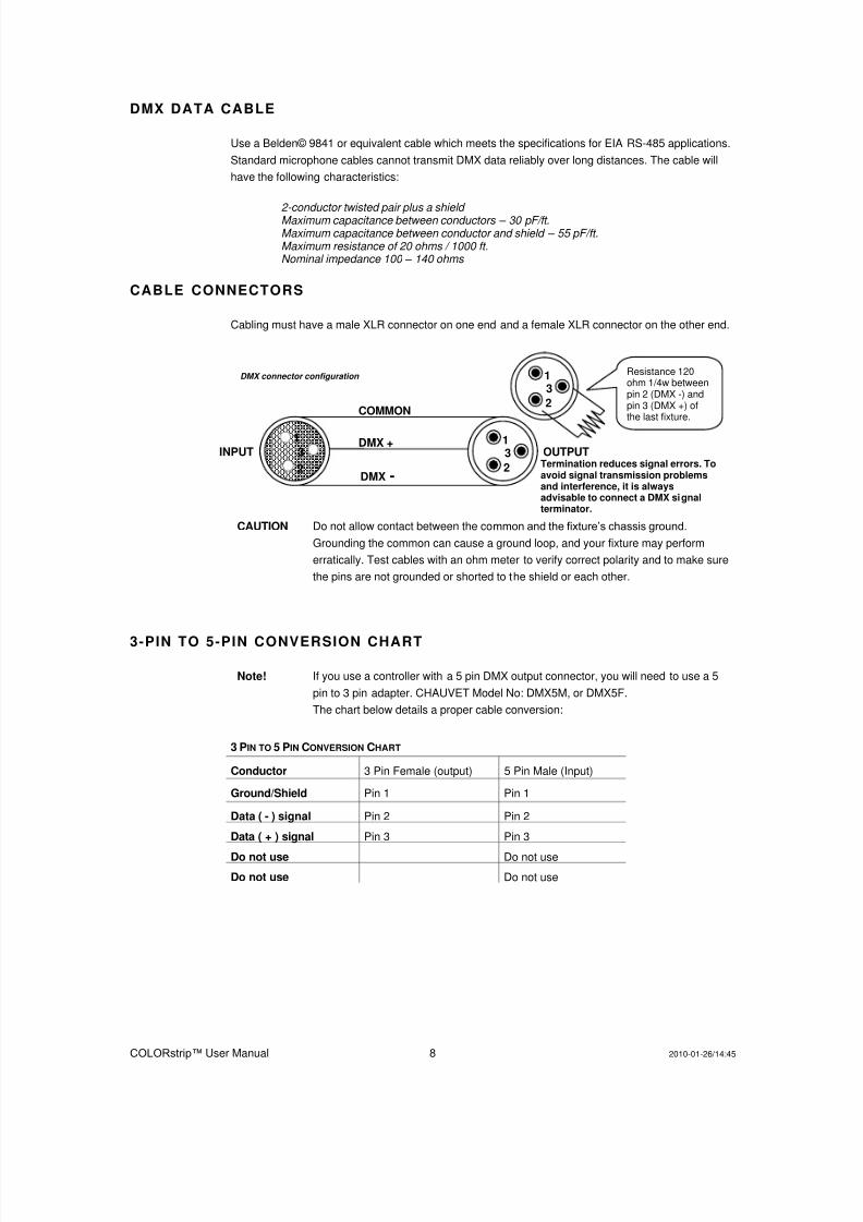
CABLE CONNECTORS
Cabling must have a male XLR connector on one end and a female XLR connector on the other end.
CAUTION Do not allow contact between the common and the fixture’s chassis ground.
Grounding the common can cause a ground loop, and your fixture may perform
erratically. Test cables with an ohm meter to verify correct polarity and to make sure
the pins are not grounded or shorted to the shield or each other.
3-PIN TO 5-PIN CONVERSION CHART
Note! If you use a controller with a 5 pin DMX output connector, you will need to use a 5
pin to 3 pin adapter. CHAUVET Model No: DMX5M, or DMX5F.
The chart below details a proper cable conversion:
3 PIN TO 5 PIN CONVERSION CHART
Conductor 3 Pin Female (output) 5 Pin Male (Input)
Ground/Shield Pin 1 Pin 1
Data ( - ) signal Pin 2 Pin 2
Data ( + ) signal Pin 3 Pin 3
Do not use Do not use
Do not use Do not use
COMMON
DMX +
DMX -
INPUT OUTPUT 1
3
2
1 3
2
1 3
2
Resistance 120ohm 1/4w betweenpin 2 (DMX -) andpin 3 (DMX +) ofthe last fixture.
Termination reduces signal errors. Toavoid signal transmission problemsand interference, it is alwaysadvisable to connect a DMX signalterminator.
DMX connector configuration
8/7/2019 Color Strip Rev02 Um
http://slidepdf.com/reader/full/color-strip-rev02-um 9/19
COLORstrip™ User Manual 9 2010-01-26/14:45
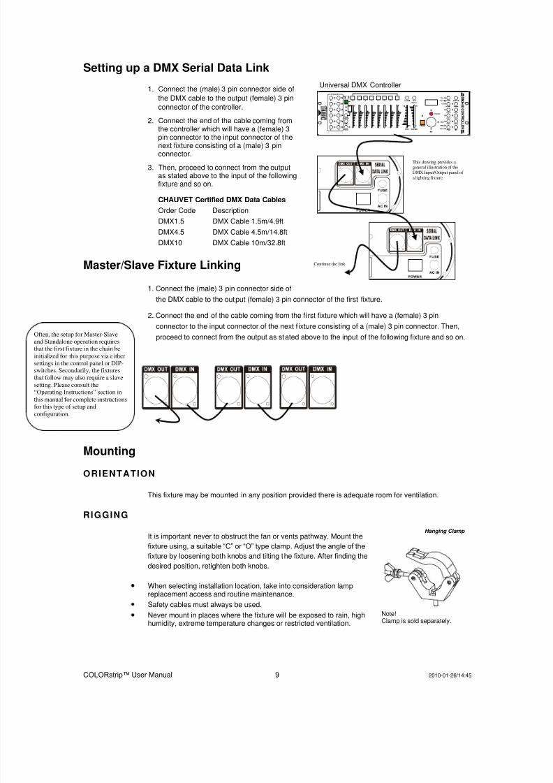
This drawing provides ageneral illustration of the
DMX Input/Output panel of
a lighting fixture.
Universal DMX Controller
Continue the link
Hanging Clamp
Note!Clamp is sold separately.
Often, the setup for Master-Slave
and Standalone operation requires
that the first fixture in the chain be
initialized for this purpose via e ither
settings in the control panel or DIP-
switches. Secondarily, the fixtures
that follow may also require a slave
setting. Please consult the
“Operating Instructions” section in
this manual for complete instructions
for this type of setup and
configuration.
Setting up a DMX Serial Data Link
1. Connect the (male) 3 pin connector side of
the DMX cable to the output (female) 3 pin
connector of the controller.
2. Connect the end of the cable coming fromthe controller which will have a (female) 3
pin connector to the input connector of thenext fixture consisting of a (male) 3 pinconnector.
3. Then, proceed to connect from the outputas stated above to the input of the followingfixture and so on.
CHAUVET Certified DMX Data Cables
Order Code Description
DMX1.5 DMX Cable 1.5m/4.9ft
DMX4.5 DMX Cable 4.5m/14.8ft
DMX10 DMX Cable 10m/32.8ft
Master/Slave Fixture Linking
1. Connect the (male) 3 pin connector side of
the DMX cable to the output (female) 3 pin connector of the first fixture.
2. Connect the end of the cable coming from the fi rst fixture which will have a (female) 3 pin
connector to the input connector of the next f ixture consisting of a (male) 3 pin connector. Then,
proceed to connect from the output as stated above to the input of the following fixture and so on.
Mounting
ORIENTATION
This fixture may be mounted in any position provided there is adequate room for ventilation.
RIGGING
It is important never to obstruct the fan or vents pathway. Mount the
fixture using, a suitable “C” or “O” type clamp. Adjust the angle of thefixture by loosening both knobs and tilting the fixture. After finding the
desired position, retighten both knobs.
When selecting installation location, take into consideration lampreplacement access and routine maintenance.
Safety cables must always be used.
Never mount in places where the fixture will be exposed to rain, highhumidity, extreme temperature changes or restricted ventilation.

8/7/2019 Color Strip Rev02 Um
http://slidepdf.com/reader/full/color-strip-rev02-um 10/19
COLORstrip™ User Manual 10 2010-01-26/14:45
Mode Enter Up Down
Mode Function & number
4. OPERATING INSTRUCTIONS The COLORstrip™ is a DMX-512 controllable, full RGB color mixing LED strip light fixture made up of
highly efficient and super bright LEDs. There are four flood spot led surfaces whose intensity can be
controlled together allowing the creation of an unlimited range of colors.
The COLORstrip™ can operate in Stand-Alone, Master/Slave and via DMX-512 control utilizing 4
channels of control.
Using the control panel
1. Press the [MODE] button repeatedly until the
display reads the mode function you wish to
change.
2. Press the [DOWN] or [UP] buttons to toggle or
scroll through values that pertain to that
function.
3. Press [ENTER] to enter the sub-menus.
Control Panel Modes & Functions
MODE FUNC PROGRAM FUNCTION/PROGRAM ( P ) RUN SPEED ( F ) FLASH SPEED ( C ) COLOR
ACt A 000
000 Blackout
001 Red 000 – 100
002 Green 000 - 100
003 Blue 000 - 100
004 Yellow 000 - 100
005 Purple 000 - 100
006 Cyan 000 - 100
007 White 000 - 100
008 Color Change 1
Automatic
000 - 050
Sound Active051 - 100
000 - 100009 Color Change 2 000 - 100
010 Color Change 3 000 - 100
011 Color Change 4 000 - 100
012 Color Change 5
013 Color Change 6
014 Sequential Color Chase 1
015 Sequential Color Chase 2
016 Sequential Color Chase 3
017 Sequential Color Chase 4
018 Sequential Color Chase 5
019 Sequential Color Chase 6
020 Sequential Color Chase 7
021 RGB Red (000-100) Green (000-100) Blue (000-10
022 Color Fade 000-100
023 Automatic Program (Sound)
SYS
S dAd DMX Channel Addressing
S AadRe-initialize fixture
Re-establishes correct number of down-link fixtures for sequential color chase runs.
8/7/2019 Color Strip Rev02 Um
http://slidepdf.com/reader/full/color-strip-rev02-um 11/19
COLORstrip™ User Manual 11 2010-01-26/14:45
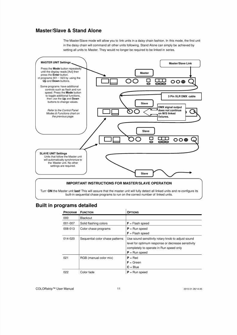
Master/Slave & Stand Alone
The Master/Slave mode will allow you to link units in a daisy chain fashion. In this mode, the first unit
in the daisy chain will command all other units following. Stand Alone can simply be achieved by
setting all units to Master. They would no longer be required to be linked in series.
Built in programs detailed
PROGRAM FUNCTION OPTIONS
000 Blackout
001-007 Solid flashing colors F = Flash speed
008-013 Color chase programs P = Run speed
F = Flash speed014-020 Sequential color chase patterns Use sound sensitivity rotary knob to adjust sound
level for optimum response or decrease sensitivity
completely to operate in Run speed only
P = Run speed
021 RGB (manual color mix) P = Red
F = Green
C = Blue
022 Color fade P = Run speed
MASTER UNIT Settings
Press the Mode button repeatedlyuntil the display reads [Act] thenpress the Enter button.
ct programs 001 ~ 023 by using theUp and Down buttons.
Some programs have additionalcontrols such as flash and runspeed. Press the Mode buttonto toggle additional functions,then use the Up and Down buttons to change values.
Refer to the Control Panel Modes & Functions chart on
the previous page.
3 Pin XLR DMX cable
SLAVE UNIT SettingsUnits that follow the Master unit will automatically synchronize to
the Master unit. No othersettings are required.
Master
Slave
Slave
Slave
Master/Slave Link
IMPORTANT INSTRUCTIONS FOR MASTER/SLAVE OPERATION
Turn ON the Master unit last! This will assure that the master unit will fully detect all linked units and re-configure itsbuilt-in sequential chase programs to run on the correct number of linked units.
DMX signal outputdoes not continue on M/S linked fixtures.
8/7/2019 Color Strip Rev02 Um
http://slidepdf.com/reader/full/color-strip-rev02-um 12/19
COLORstrip™ User Manual 12 2010-01-26/14:45
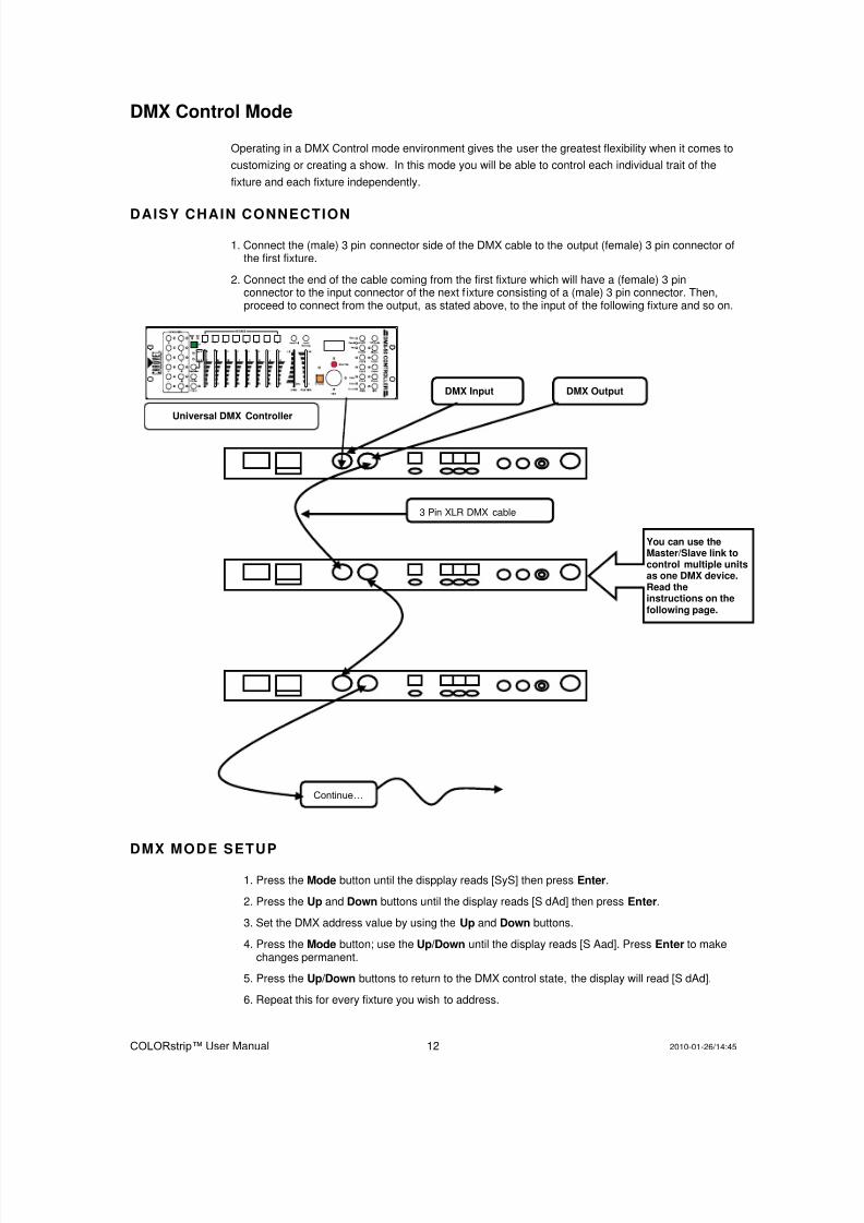
DMX Control Mode
Operating in a DMX Control mode environment gives the user the greatest flexibility when it comes to
customizing or creating a show. In this mode you will be able to control each individual trait of the
fixture and each fixture independently.
DAISY CHAIN CONNECTION
1. Connect the (male) 3 pin connector side of the DMX cable to the output (female) 3 pin connector ofthe first fixture.
2. Connect the end of the cable coming from the first fixture which will have a (female) 3 pinconnector to the input connector of the next f ixture consisting of a (male) 3 pin connector. Then,proceed to connect from the output, as stated above, to the input of the following fixture and so on.
DMX MODE SETUP
1. Press the Mode button until the dispplay reads [SyS] then press Enter.
2. Press the Up and Down buttons until the display reads [S dAd] then press Enter.
3. Set the DMX address value by using the Up and Down buttons.
4. Press the Mode button; use the Up/Down until the display reads [S Aad]. Press Enter to makechanges permanent.
5. Press the Up/Down buttons to return to the DMX control state, the display will read [S dAd].
6. Repeat this for every fixture you wish to address.
3 Pin XLR DMX cable
Continue…
Universal DMX Controller
DMX Input DMX Output
You can use theMaster/Slave link tocontrol multiple unitsas one DMX device.Read the instructions on the following page.
8/7/2019 Color Strip Rev02 Um
http://slidepdf.com/reader/full/color-strip-rev02-um 13/19
COLORstrip™ User Manual 13 2010-01-26/14:45
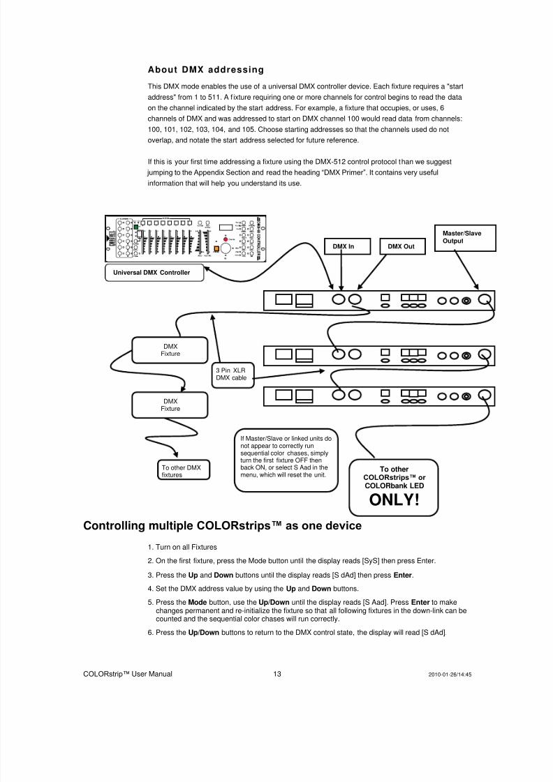
About DMX addressing
This DMX mode enables the use of a universal DMX controller device. Each fixture requires a "start
address" from 1 to 511. A f ixture requiring one or more channels for control begins to read the data
on the channel indicated by the start address. For example, a fixture that occupies, or uses, 6
channels of DMX and was addressed to start on DMX channel 100 would read data from channels:
100, 101, 102, 103, 104, and 105. Choose starting addresses so that the channels used do not
overlap, and notate the start address selected for future reference.
If this is your first time addressing a fixture using the DMX-512 control protocol than we suggest
jumping to the Appendix Section and read the heading “DMX Primer”. It contains very useful
information that will help you understand its use.
Controlling multiple COLORstrips™ as one device
1. Turn on all Fixtures
2. On the first fixture, press the Mode button until the display reads [SyS] then press Enter.
3. Press the Up and Down buttons until the display reads [S dAd] then press Enter.
4. Set the DMX address value by using the Up and Down buttons.
5. Press the Mode button, use the Up/Down until the display reads [S Aad]. Press Enter to makechanges permanent and re-initialize the fixture so that all following fixtures in the down-link can becounted and the sequential color chases will run correctly.
6. Press the Up/Down buttons to return to the DMX control state, the display will read [S dAd].
3 Pin XLRDMX cable
Universal DMX Controller
DMXFixture
DMX
Fixture
To other DMX fixtures
To otherCOLORstrips™ or
COLORbank LED
ONLY!
DMX In DMX Out
Master/Slave Output
If Master/Slave or linked units donot appear to correctly runsequential color chases, simplyturn the first fixture OFF thenback ON, or select S Aad in themenu, which will reset the unit.

8/7/2019 Color Strip Rev02 Um
http://slidepdf.com/reader/full/color-strip-rev02-um 14/19
COLORstrip™ User Manual 14 2010-01-26/14:45
8/7/2019 Color Strip Rev02 Um
http://slidepdf.com/reader/full/color-strip-rev02-um 15/19
COLORstrip™ User Manual 15 2010-01-26/14:45
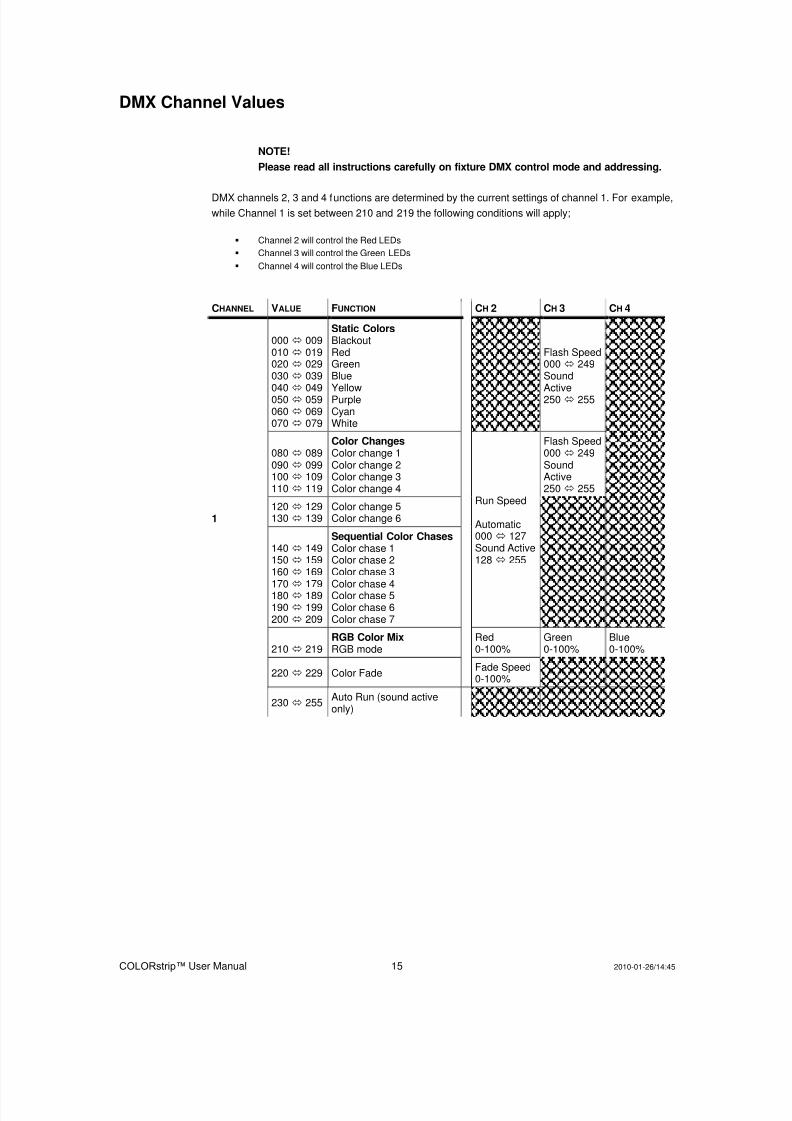
DMX Channel Values
NOTE!
Please read all instructions carefully on fixture DMX control mode and addressing.
DMX channels 2, 3 and 4 functions are determined by the current settings of channel 1. For example,
while Channel 1 is set between 210 and 219 the following conditions will apply;
Channel 2 will control the Red LEDs
Channel 3 will control the Green LEDs
Channel 4 will control the Blue LEDs
CHANNEL VALUE FUNCTION CH 2 CH 3 CH 4
1
000 009010 019020 029030 039
040
049050 059060 069070 079
Static ColorsBlackout RedGreenBlue
YellowPurpleCyanWhite
Flash Speed000 249Sound
Active250 255
080 089090 099100 109110 119
Color ChangesColor change 1Color change 2Color change 3Color change 4
Run Speed
Automatic000 127Sound Active128 255
Flash Speed000 249SoundActive250 255
120 129130 139
Color change 5Color change 6
140 149150 159160 169
170
179180 189190 199200 209
Sequential Color ChasesColor chase 1Color chase 2Color chase 3
Color chase 4Color chase 5Color chase 6Color chase 7
210 219RGB Color MixRGB mode
Red0-100%
Green0-100%
Blue0-100%
220 229 Color FadeFade Speed0-100%
230 255Auto Run (sound activeonly)
8/7/2019 Color Strip Rev02 Um
http://slidepdf.com/reader/full/color-strip-rev02-um 16/19
COLORstrip™ User Manual 16 2010-01-26/14:45
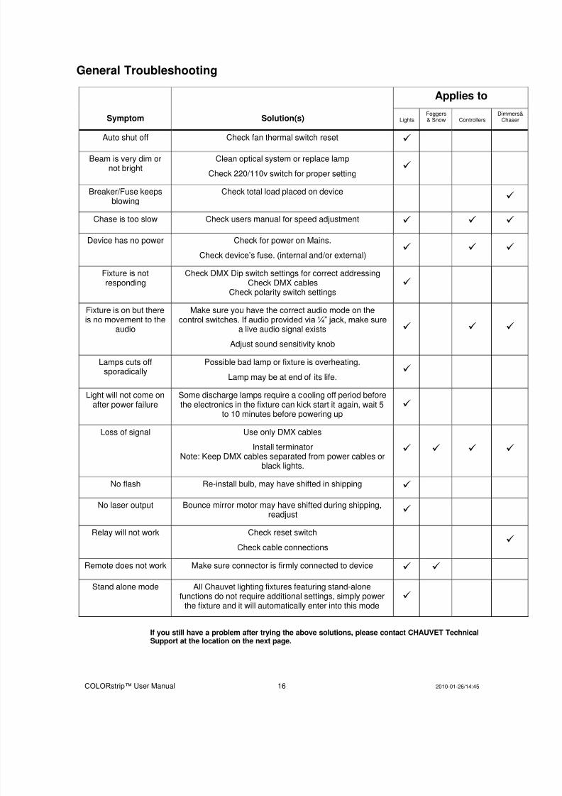
General Troubleshooting
Symptom Solution(s)
Applies to
LightsFoggers& Snow Controllers
Dimmers&Chaser
Auto shut off Check fan thermal switch reset
Beam is very dim ornot bright
Clean optical system or replace lamp
Check 220/110v switch for proper setting
Breaker/Fuse keepsblowing
Check total load placed on device
Chase is too slow Check users manual for speed adjustment
Device has no power Check for power on Mains.
Check device’s fuse. (internal and/or external)
Fixture is notresponding
Check DMX Dip switch settings for correct addressingCheck DMX cables
Check polarity switch settings
Fixture is on but thereis no movement to the
audio
Make sure you have the correct audio mode on thecontrol switches. If audio provided via ¼” jack, make sure
a live audio signal exists
Adjust sound sensitivity knob
Lamps cuts offsporadically
Possible bad lamp or fixture is overheating.
Lamp may be at end of its life.
Light will not come onafter power failure
Some discharge lamps require a cooling off period beforethe electronics in the fixture can kick start it again, wait 5
to 10 minutes before powering up
Loss of signal Use only DMX cables
Install terminatorNote: Keep DMX cables separated from power cables or
black lights.
No flash Re-install bulb, may have shifted in shipping
No laser output Bounce mirror motor may have shifted during shipping,readjust
Relay will not work Check reset switch
Check cable connections
Remote does not work Make sure connector is firmly connected to device
Stand alone mode All Chauvet lighting fixtures featuring stand-alonefunctions do not require additional settings, simply power
the fixture and it will automatically enter into this mode
If you still have a problem after trying the above solutions, please contact CHAUVET TechnicalSupport at the location on the next page.
8/7/2019 Color Strip Rev02 Um
http://slidepdf.com/reader/full/color-strip-rev02-um 17/19
COLORstrip™ User Manual 17 2010-01-26/14:45
Technical Support
Address: Service Dept.3000 N 29th Ct, Hollywood, FL 33020 (U.S.A.)Support (Email): [email protected]: (954) 929-1115 - (Press 4)
Fax: (954) 929-5560 - (Attention: Service)Website: http://www.chauvetlighting.com
5. APPENDIX DMX Primer
There are 512 channels in a DMX-512 connection. Channels may be assigned in any manner. A
fixture capable of receiving DMX 512 will require one or a number of sequential channels. The user
must assign a starting address on the fixture that indicates the first channel reserved in the controller.
There are many different types of DMX controllable fixtures and they all may vary in the total number
of channels required. Choosing a start address should be planned in advance. Channels should
never overlap. If they do, this will result in erratic operation of the fixtures whose starting address is
set incorrectly. You can however, control multiple fixtures of the same type using the same starting
address as long as the intended result is that of unison movement or operation. In other words, the
fixtures will be slaved together and all respond exactly the same.
DMX fixtures are designed to receive data through a serial Daisy Chain. A Daisy Chain connection is
where the DATA OUT of one fixture connects to the DATA IN of the next fixture. The order in which
the fixtures are connected is not important and has no effect on how a controller communicates to
each fixture. Use an order that provides for the easiest and most direct cabling. Connect fixtures
using shielded two conductor twisted pair cable with three pin XLR male to female connectors. The
shield connection is pin 1, while pin 2 is Data Negative (S-) and pin 3 is Data positive (S+). CHAUVET
carries 3-pin XLR DMX compliant cables, DMX-10 (33’), DMX-4.5 (15’) and DMX-1.5 (5’)

8/7/2019 Color Strip Rev02 Um
http://slidepdf.com/reader/full/color-strip-rev02-um 18/19
COLORstrip™ User Manual 18 2010-01-26/14:45
General Maintenance
To maintain optimum performance and minimize wear fixtures should be cleaned frequently. Usage
and environment are contributing factors in determining frequency. As a general rule, f ixtures should
be cleaned at least twice a month. Dust build up reduces light output performance and can cause
overheating. This can lead to reduced lamp life and increased mechanical wear. Be sure to power off
fixture before conducting maintenance.
Unplug fixture from power. Use a vacuum or air compressor and a soft brush to remove dust
collected on external vents and internal components. Clean all glass when the fixture is cold with a
mild solution of glass cleaner or Isopropyl Alcohol and a soft lint free cotton cloth or lens tissue. Apply
solution to the cloth or t issue and drag dirt and grime to the outside of the lens. Gently polish optical
surfaces until they are free of haze and lint.
The cleaning of internal and external optical lenses and/or mirrors must be carried out periodically to
optimize light output. Cleaning frequency depends on the environment in which the fixture operates:
damp, smoky or particularly dirty surrounding can cause greater accumulation of dirt on the unit’s
optics. Clean with soft cloth using normal glass cleaning fluid. - Always dry the parts carefully. - Clean
the external optics at least every 20 days. Clean the internal optics at least every 30/60 days.
Returns Procedure
Returned merchandise must be sent prepaid and in the original packing, call tags will not be issued.
Package must be clearly labeled with a Return Merchandise Authorization Number (RA #). Products
returned without an RA # will be refused. Call CHAUVET and request RA # prior to shipping the
fixture. Be prepared to provide the model number, serial number and a brief description of the cause
for the return. Be sure to properly pack fixture, any shipping damage resulting from inadequate
packaging is the customer’s responsibility. CHAUVET reserves the right to use its own discretion to
repair or replace product(s). As a suggestion, proper UPS packing or double-boxing is always a safe
method to use.
Note: If you are given an RA #, please include the following information on a piece of paperinside the box:
1) Your name
2) Your address
3) Your phone number
4) The RA #
5) A brief description of the symptoms
Claims
Damage incurred in shipping is the responsibility of the shipper; therefore the damage must be
reported to the carrier upon receipt of merchandise. It is the customer's responsibility to notify andsubmit claims with the shipper in the event that a fixture is damaged due to shipping. Any other claim
for items such as missing component/part, damage not related to shipping, and concealed damage,
must be made within seven (7) days of receiving merchandise.
8/7/2019 Color Strip Rev02 Um
http://slidepdf.com/reader/full/color-strip-rev02-um 19/19
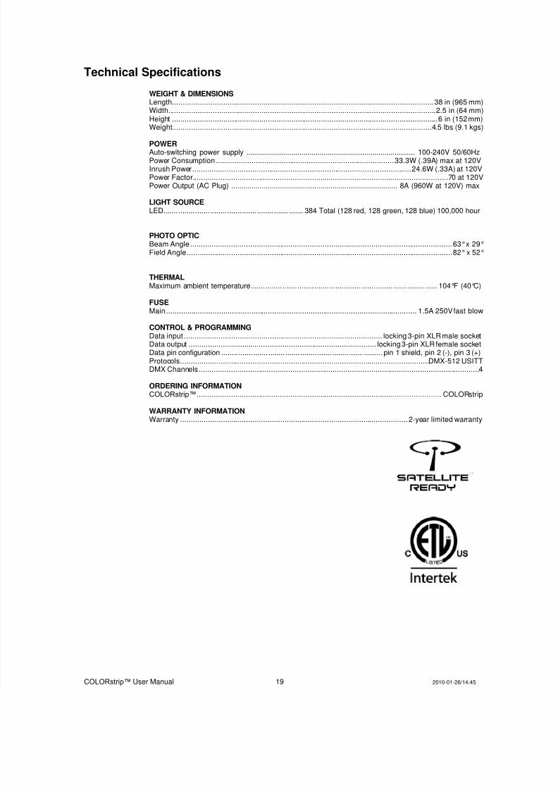
Technical Specifications
WEIGHT & DIMENSIONSLength ........................................................................................................................... 38 in (965 mm)Width.............................................................................................................................. 2.5 in (64 mm)Height ............................................................................................................................. 6 in (152 mm)Weight.......................................................................................................................... 4.5 lbs (9.1 kgs)
POWERAuto-switching power supply ................................................................................... 100-240V 50/60HzPower Consumption .................................................................................... 33.3W (.39A) max at 120VInrush Power ....................................................................................................... 24.6W (.33A) at 120VPower Factor ....................................................................................................................... .70 at 120VPower Output (AC Plug) .................................................................................. 8A (960W at 120V) max
LIGHT SOURCELED ....... ........ ....... ........ ....... ....... ........ ....... ....... 384 Total (128 red, 128 green, 128 blue) 100,000 hour
PHOTO OPTICBeam Angle ........................................................................................................................... 63°x 29°Field Angle ............................................................................................................................. 82°x 52°
THERMALMaximum ambient temperature ....... ........ ....... ........ ....... ....... ........ ....... ........ ....... ........ ...... 104°F (40°C)
FUSEMain ...................................................................................................................... 1.5A 250V fast blow
CONTROL & PROGRAMMINGData input ............................................................................................. locking 3-pin XLR male socketData output ........................................................................................ locking 3-pin XLR female socketData pin configuration ........ ....... ....... ........ ....... ........ ....... ........ ....... ........ . pin 1 shield, pin 2 (-), pin 3 (+)Protocols ..................................................................................................................... DMX-512 USITTDMX Channels .................................................................................................................................... 4
ORDERING INFORMATIONCOLORstrip™................................................................................................................... COLORstrip
WARRANTY INFORMATIONWarranty ........................................................................................................... 2-year limited warranty