
Color Imaging and Pattern Hiding on a Metallic Substratelsp · ACM Reference Format Pjanic, P.,...
10
ACM Reference Format Pjanic, P., Hersch, R. 2015. Color Imaging and Pattern Hiding on a Metallic Substrate. ACM Trans. Graph. 34, 4, Article 130 (August 2015), 10 pages. DOI = 10.1145/2766944 http://doi.acm.org/10.1145/2766944. Copyright Notice Permission to make digital or hard copies of all or part of this work for personal or classroom use is granted without fee provided that copies are not made or distributed for profit or commercial advantage and that copies bear this notice and the full citation on the first page. Copyrights for components of this work owned by others than ACM must be honored. Abstracting with credit is permitted. To copy otherwise, or republish, to post on servers or to redistribute to lists, requires prior specific permission and/or a fee. Request permis- sions from [email protected]. SIGGRAPH ‘15 Technical Paper, August 09 – 13, 2015, Los Angeles, CA. Copyright 2015 ACM 978-1-4503-3331-3/15/08 ... $15.00. DOI: http://doi.acm.org/10.1145/2766944 Color Imaging and Pattern Hiding on a Metallic Substrate Petar Pjanic, Roger D. Hersch Ecole Polytechnique Fédérale de Lausanne (EPFL) Abstract We present a new approach for the reproduction of color images on a metallic substrate that look bright and colorful under specular reflection observation conditions and also look good under non- specular reflection observation conditions. We fit amounts of both the white ink and the classical cyan, magenta and yellow inks according to a formula optimizing the reproduction of colors simultaneously under specular and non-specular observation conditions. In addition, we can hide patterns such as text or graphical symbols in one viewing mode, specular or non-specular, and reveal them in the other viewing mode. We rely on the trade- off between amounts of white diffuse ink and amounts of cyan, magenta and yellow inks to control lightness in specular and in non-specular observation conditions. Further effects are grayscale images that alternate from a first image to a second independent image when tilting the print from specular to non-specular reflec- tion observation conditions. Applications comprise art and enter- tainment, publicity, posters, as well as document security. CR Categories: I.3.3 [Computer Graphics]: Picture/Image Gen- eration—Viewing and display algorithms; Keywords: Color reproduction, document security, color prints on metal, pattern hiding, image alternations, white diffuse ink, specular versus diffuse reflection. 1 Introduction Direct prints on a pure metallic substrate provide bright and bril- liant colors when seen under specular reflection, but they look dark and dull when viewed under non-specular reflection [Pjanic and Hersch 2013]. Such prints are becoming commercially avail- able for advertisement purposes and for the decoration of private homes. In the present contribution, we aim at producing partly specular reflecting and partly diffusely reflecting prints that look bright and colorful under specular and also look nice under non-specular observation angles. We rely on the ability to print on top of the metallic substrate diffusely reflecting white ink halftones that reduce the specular reflection component and increase the diffuse reflection component of the print. In addition, we offer the possibility of hiding patterns within a grayscale or color image when seen under specular viewing an- gles and make them appear when viewed under non-specular viewing angles or vice versa. _______________________ We rely on the fact that increasing the amount of white ink dark- ens the image in specular viewing mode but increases the light- ness of the image in the non-specular viewing mode and that the increase of similar amounts of cyan, magenta and yellow inks darkens the image both in specular and non-specular viewing modes. Thanks to the trade-off between the amounts of the white and of the colored inks, the lightness can be kept constant in one viewing mode and can be varied in the second viewing node. This also enables us to produce a metallic print that shows a first grayscale image in one viewing mode, and then, by tilting it to the other viewing mode, shows a second independent grayscale image. We had to meet a number of challenges. The first challenge con- sisted in creating a color reproduction workflow that enables finding surface coverages of inks yielding colors similar to the original colors under both specular and non-specular observation conditions. This is achieved by having accurate models predicting the colors of the prints as a function of the amounts of inks under either specular or non-specular observation conditions. Then, with an objective function that minimizes a difference metric between original color and specular color and between original color and non-specular color, one obtains optimal surface coverages of the diffusing white and of the classical cyan, magenta and yellow inks. Since we would like to hide patterns under specular reflection and reveal them under non-specular reflection or vice-versa, a second challenge consisted in determining the gamut of print colors that for each color in one viewing mode provides a sufficiently large variety of lightnesses in the other viewing mode. For this purpose, a second objective function was created whose minimization provides ink surface coverages for reproducing a desired color in the first viewing mode and at the same time enables creating a modified lightness in the second viewing mode. In contrast to prior work on appearance reproduction [e.g. Matu- sik et al. 2009, Lan et al. 2013], we take in respect to angular reflectances a “coarse grain” approach and consider only the two extreme cases, namely specular reflection and non-specular re- flection. However in respect to color rendition, we take a “fine grain” approach which is necessary for pattern hiding. We fit surface coverages of the inks by relying on a first spectral predic- tion model making accurate predictions under the specular view- ing conditions (25 o :25 o ) and on a second prediction model making accurate predictions under the non-specular viewing conditions (45 o :0 o ). Our novel contributions are the following: (i) The idea of the trade-off between amounts of white diffuse ink and amounts of cyan, magenta and yellow inks to control CIELAB colors in specular and in non-specular observation con- ditions. (ii) The simultaneous consideration of two spectral prediction models, one for specular and one for non-specular viewing condi- tions. (iii) The idea that reducing the size of a gamut in one of the two viewing modes offers freedom to have lightness variations in the other viewing mode. (iv) Optimization formula and color separations to produce color images that can be viewed both under specular and non-specular viewing conditions. ACM Transactions on Graphics, Vol. 34, No. 4, Article 130, Publication Date: August 2015
Transcript of Color Imaging and Pattern Hiding on a Metallic Substratelsp · ACM Reference Format Pjanic, P.,...

ACM Reference FormatPjanic, P., Hersch, R. 2015. Color Imaging and Pattern Hiding on a Metallic Substrate. ACM Trans. Graph. 34, 4, Article 130 (August 2015), 10 pages. DOI = 10.1145/2766944 http://doi.acm.org/10.1145/2766944.
Copyright NoticePermission to make digital or hard copies of all or part of this work for personal or classroom use is granted without fee provided that copies are not made or distributed for profi t or commercial advantage and that copies bear this notice and the full citation on the fi rst page. Copyrights for components of this work owned by others than ACM must be honored. Abstracting with credit is permitted. To copy otherwise, or republish, to post on servers or to redistribute to lists, requires prior specifi c permission and/or a fee. Request permis-sions from [email protected] ‘15 Technical Paper, August 09 – 13, 2015, Los Angeles, CA.Copyright 2015 ACM 978-1-4503-3331-3/15/08 ... $15.00.DOI: http://doi.acm.org/10.1145/2766944
Color Imaging and Pattern Hiding on a Metallic Substrate
Petar Pjanic, Roger D. Hersch
Ecole Polytechnique Fédérale de Lausanne (EPFL)
Abstract We present a new approach for the reproduction of color images on a metallic substrate that look bright and colorful under specular reflection observation conditions and also look good under non-specular reflection observation conditions. We fit amounts of both the white ink and the classical cyan, magenta and yellow inks according to a formula optimizing the reproduction of colors simultaneously under specular and non-specular observation conditions. In addition, we can hide patterns such as text or graphical symbols in one viewing mode, specular or non-specular, and reveal them in the other viewing mode. We rely on the trade-off between amounts of white diffuse ink and amounts of cyan, magenta and yellow inks to control lightness in specular and in non-specular observation conditions. Further effects are grayscale images that alternate from a first image to a second independent image when tilting the print from specular to non-specular reflec-tion observation conditions. Applications comprise art and enter-tainment, publicity, posters, as well as document security.
CR Categories: I.3.3 [Computer Graphics]: Picture/Image Gen-eration—Viewing and display algorithms;
Keywords: Color reproduction, document security, color prints on metal, pattern hiding, image alternations, white diffuse ink, specular versus diffuse reflection.
1 Introduction
Direct prints on a pure metallic substrate provide bright and bril-liant colors when seen under specular reflection, but they look dark and dull when viewed under non-specular reflection [Pjanic and Hersch 2013]. Such prints are becoming commercially avail-able for advertisement purposes and for the decoration of private homes.
In the present contribution, we aim at producing partly specular reflecting and partly diffusely reflecting prints that look bright and colorful under specular and also look nice under non-specular observation angles. We rely on the ability to print on top of the metallic substrate diffusely reflecting white ink halftones that reduce the specular reflection component and increase the diffuse reflection component of the print.
In addition, we offer the possibility of hiding patterns within a grayscale or color image when seen under specular viewing an-gles and make them appear when viewed under non-specular viewing angles or vice versa. _______________________
We rely on the fact that increasing the amount of white ink dark-ens the image in specular viewing mode but increases the light-ness of the image in the non-specular viewing mode and that the increase of similar amounts of cyan, magenta and yellow inks darkens the image both in specular and non-specular viewing modes.
Thanks to the trade-off between the amounts of the white and of the colored inks, the lightness can be kept constant in one viewing mode and can be varied in the second viewing node. This also enables us to produce a metallic print that shows a first grayscale image in one viewing mode, and then, by tilting it to the other viewing mode, shows a second independent grayscale image.
We had to meet a number of challenges. The first challenge con-sisted in creating a color reproduction workflow that enables finding surface coverages of inks yielding colors similar to the original colors under both specular and non-specular observation conditions. This is achieved by having accurate models predicting the colors of the prints as a function of the amounts of inks under either specular or non-specular observation conditions. Then, with an objective function that minimizes a difference metric between original color and specular color and between original color and non-specular color, one obtains optimal surface coverages of the diffusing white and of the classical cyan, magenta and yellow inks.
Since we would like to hide patterns under specular reflection and reveal them under non-specular reflection or vice-versa, a second challenge consisted in determining the gamut of print colors that for each color in one viewing mode provides a sufficiently large variety of lightnesses in the other viewing mode. For this purpose, a second objective function was created whose minimization provides ink surface coverages for reproducing a desired color in the first viewing mode and at the same time enables creating a modified lightness in the second viewing mode.
In contrast to prior work on appearance reproduction [e.g. Matu-sik et al. 2009, Lan et al. 2013], we take in respect to angular reflectances a “coarse grain” approach and consider only the two extreme cases, namely specular reflection and non-specular re-flection. However in respect to color rendition, we take a “fine grain” approach which is necessary for pattern hiding. We fit surface coverages of the inks by relying on a first spectral predic-tion model making accurate predictions under the specular view-ing conditions (25o:25o) and on a second prediction model making accurate predictions under the non-specular viewing conditions (45o:0o).
Our novel contributions are the following:
(i) The idea of the trade-off between amounts of white diffuse ink and amounts of cyan, magenta and yellow inks to control CIELAB colors in specular and in non-specular observation con-ditions.
(ii) The simultaneous consideration of two spectral prediction models, one for specular and one for non-specular viewing condi-tions.
(iii) The idea that reducing the size of a gamut in one of the two viewing modes offers freedom to have lightness variations in the other viewing mode.
(iv) Optimization formula and color separations to produce color images that can be viewed both under specular and non-specular viewing conditions.
ACM Transactions on Graphics, Vol. 34, No. 4, Article 130, Publication Date: August 2015

2 Related work
Stollnitz et al. [1998] reproduced color images with sets of opti-mally selected custom inks by minimizing a cost function relying on a model predicting the printed color as a function of ink sur-face coverages and ink reflectances. Mikula et al. [2003] analyzed the effect of gloss on the reflectance of an ink printed on alumin-ium, in function of the detection angle. They measured increases in lightness and chroma when evolving from non-specular to specular observation angles.
Hersch et al. [2003] created a new security feature by combining a silver ink and standard inks to print on paper color images with embedded metallic color patterns. In contrast to the present con-tribution, the early prediction model used in that work was able to hide these patterns only under non-specular observation angles.
Pjanic and Hersch [2013] created a color reproduction workflow for printing with classical inks on a metallic substrate. In order to establish the correspondance between amounts of inks and result-ing color under specular reflection, they used an ink spreading enhanced cellular Yule-Nielsen spectral prediction model. This model is calibrated with patch reflectances measured under specu-lar reflection. The resulting printed colors appear bright and color-ful under specular reflection, but look dark and colorless under non-specular reflection.
Matusik et al. [2009] extended classical color reproduction with the aim of reproducing also the BRDF of a flat original. They used a blend of classical inks and of glossy metallic inks with specific BRDF’s and reproduced the original by an extended halftoning process. Malzbender et al. [2012] used halftoning on top of an array of specularly reflecting spherical depressions to create images with desired reflection functions.
Dong et al. [2012] proposed a method for printing high dynamic range images that show the equivalent of different exposures under different viewing angles. They relied on the fact that a spatially varying glossiness can be obtained by printing on a metallic substrate selectable amounts of white diffuse ink in addi-tion to classical cyan, magenta and yellow inks.
Lan et al. [2013] propose a method for fabricating surfaces with desired spatially-varying BRDF’s, including anisotropic ones. They fabricate patches with oriented faces, coat them with a silver layer and print them with amounts of white, and classical inks in order to create an appearance as close as possible to the desired appearance.
Recently, a wider range of spatially-varying reflectance functions has be synthesized by relying on wave interference [Levin et al. 2013; Glasner et al. 2014; Ye et al. 2014].
Further works that aim at creating surprising images by optical effects comprise illuminated arrays of oriented microfacets that enable synthesizing caustic images by reflection or refraction [Weyrich et al. 2009; Papas et al. 2010]. Papas et al. [2012] cre-ated oriented microfacets that warp by refraction unstructured source images into meaningful target images. By relying on shad-owing effects, optimized 2.5D reliefs enable embedding images that are revealed when lit from appropriate directions [Alexa and Matusik 2010; Bermano et al. 2012].
In a similar vein as the works described above, the approaches proposed in the present contribution aim at creating new surpris-ing effects. These effects may be of high value in the fields of art and advertisement as well as for the protection of documents and valuable articles.
3 Reasons for considering the specular and non-specular viewing conditions
Under specular viewing conditions, light coming from a given illuminating solid angle, such as a window, hits the metallic print and is specularly reflected into the viewer’s eye. We assume that the metallic color print has a moderate size (e.g. A5 or A6), is fixed on a flat support and that the window is relatively large. In this case, there is a range of viewing angles under which the print appears in specularly reflecting mode, i.e. one may tilt the print slightly in different directions and still remain in specular viewing mode. The human visual system adapts to the specular reflection. The diffusely reflecting image parts have only a very small con-tribution to the reflected light.
Under non-specular viewing conditions, the print is tilted so as to avoid the light crossing the window from being specularly re-flected into the viewer’s eyes. Only light from the window that is diffusely reflected by the print reaches the viewer’s eye. The human visual system adapts to the non-specular viewing condi-tions. The unprinted specularly reflecting metallic parts look dark (Figure 5(a), bottom).
Our goal is to correctly reproduce color images under both specu-lar and non-specular viewing conditions, to hide images under one viewing mode and reveal them under the other viewing mode and to alternate between grayscale images when tilting the print from the first to the second viewing mode. In order to achieve these goals, it is sufficient to limit our considerations to the specular and the non-specular viewing conditions, as defined above.
In the presence of several light sources, both specularly and non-specularly reflected light may reach the eye. In this case, the overall appearance will still be pleasant. However, under such a mixed illumination, except at specific illumination and viewing angles, it is not possible to hide patterns or to alternate between two independent grayscale images. Ghosting effects appear.
Regarding the optimal illumination conditions, instead of looking at the print in front of a window, one may create a setup where a flat uniformly illuminating light table is placed in a dark room. The light table may be placed at an oblique or vertical orientation and the print tilted in vertical direction so as to view it either under specular or under non-specular viewing conditions.
4 Color reproduction workflow for metallic col-or prints
A color reproduction workflow comprises a preparation phase and a printing phase (Figure 1). The preparation phase comprises the characterization of the printing device, the creation of the gamut of all printable colors, the definition of a gamut mapping strategy that maps input colors to printable colors and the creation of a relationship between desired color and ink surface coverages [Morovic and Lammens 2007]. A color reproduction table is created by sampling the input RGB 3D color space, transforming RGB colors to CIELAB [Sharma 2003], performing gamut map-ping, and for the gamut mapped colors, obtaining the correspond-ing ink surface coverages. Each RGB entry of the table contains the ink surface coverages needed to reproduce that color.
In the present work, we use a spectral prediction model to charac-terize the printer (Section 5), i.e. to establish the relationship between surface coverages of the ink dots and the resulting color. We always consider RGB input colors referenced in respect to a device independent color space, in the same manner as for exam-ple sRGB (http://www.w3.org/Graphics/Color/srgb). The conver-sion from a given RGB color space to the device-independent CIE-XYZ tri-stimulus space is assumed to be well defined.
130:2 • P. Pjanic et al.
ACM Transactions on Graphics, Vol. 34, No. 4, Article 130, Publication Date: August 2015

a) Preparation
Gamut map RGB colors to printable colors, fit ink surface coverages from printable colors
and fill the color reproduction table.
Establish the printer gamut
Spectral prediction model: from ink surface coverages predict the printed color
Color reproduction table : RGB input colors ink surface coverages
Input image RGB colors
Halftoning & printing (ink-jet, offset)
Color separations
b) Printing
Map RGB input colors to ink surface coverages
Figure 1: The color reproduction workflow comprising (a) a preparation phase and (b) a printing phase.
The workflow comprises also a printing phase where the color reproduction table is used for processing and printing the input images, i.e. for mapping input colors to corresponding ink surface coverages. This yields the color separations that are halftoned and printed (Figure 1, right).
In the present contribution, we deal with metallic prints formed by a silver substrate printable by a white diffusing ink halftone and, on top of it, classical cyan, magenta, and yellow color halftones. All samples are printed on a commercially available isotropic silver film substrate (4.7 mil thickness, 165g/m2) with an Epson Stylus Pro WT7900 inkjet printer at a resolution of 1440 dpi and at a screen frequency of 100 lpi. The light diffusing white ink clustered-dot halftone layer is printed at an angle of 15° and the cyan, magenta and yellow transparent ink halftone layers are printed dot-on-dot at the angle of 60°. For inkjet prints on metallic substrates, dot-on-dot printing of the colored inks minimizes local color variations.
As explained in Section 3, we consider two predominant observa-tion conditions, namely specular and non-specular observation conditions. We assume that under specular observation, the “whit-est” point on which the eye adapts is the unprinted metallic sur-face and that under non-specular observation, the “whitest” point is the light diffusing fulltone white ink.
Under specular viewing conditions, color halftones on silver without white ink appear very bright and colorful. After the transi-tion between specular and non-specular reflectance, they become dark and colorless (Figure 5a). In contrast, color halftones printed on top of the fulltone white ink remain bright across a large range of observation angles. Intermediate white ink halftones on silver (e.g. 30% surface coverage) are very bright at specular observa-tion angles and are also bright at non-specular observation angles. This indicates that white ink halftones have the potential to create images that have a good dynamic range under both specular and non-specular observation conditions.
In order to characterize a print under both the specular and the non-specular viewing conditions, we introduce two separate color spaces. The specular CIELAB color space used for characterizing samples viewed under specular reflection conditions is relative to the unprinted silver substrate as its “whitest color”. In contrast, the non-specular CIELAB color space for characterizing samples viewed under non-specular reflection is, in respect to its whitest color, relative to the fulltone white diffusing ink printed on top of the silver substrate.
CIELAB colors of specularly reflecting metallic print samples are obtained by measuring reflectance factors with a custom setup formed by a light source illuminating the print sample at 25o and by a fiber capturing the reflected light at 25o. The reflectance factor is obtained by dividing the captured irradiance of a color patch by the irradiance of the unprinted metallic substrate, meas-ured under the same (25o:25o) geometry. The reflectance factor is then converted to CIE-XYZ tri-stimulus values under the D65
illuminant and for the CIE 1931 Standard Observer, with the unprinted silver substrate set as Y=100 [Wyscecki and Stiles 1982, Section 3.3.8, pp. 156-157]. CIE-XYZ values are then converted to CIELAB by considering the specularly reflecting unprinted silver substrate as the reference “white object color stimulus” [Wyscecki and Stiles 1982, Section 3.3.9, pp. 166-169].
The non-specular reflectance factors are measured at a 0o incident angle and at a 45o capturing angle with a MF45 spectrophotome-ter from Datacolor. XYZ and CIELAB values are derived in the same way as for the specular colors, but with the fulltone white ink as the white reference.
5 Spectral model for predicting the color of metallic prints
A spectral prediction model creates the relationship between amounts of inks deposited on a given substrate and the resulting printed color viewed under specific illumination and observation conditions. The spectral prediction model is calibrated by measur-ing the reflection spectra of all Neugebauer primaries (substrate, fulltone inks and their superpositions) as well as of a number of halftones. We use as prediction model the cyan (c), magenta (m), and yellow (y) based cellular Yule-Nielsen modified spectral Neugebauer model (CYNSN) for dot-on-dot halftones, with one level of subdivision [Balasubramanian 1999], see also the Sup-plementary Material. The 3D c,m,y ink surface coverage space is divided into 23=8 subcubes with vertices at 0, 50% and 100% nominal surface coverages of each of the inks. There are therefore 33=27 primary reflectances. The Yule-Nielsen modified spectral Neugebauer model (YNSN) is separately applied on each sub-cube.
To account for ink spreading, the central point within each sub-cube is printed and measured. The three c,m,y ink surface cover-ages are fitted to minimize the square difference between the measured spectral reflectance and the reflectance predicted by the CYNSN model. This yields within each subcube and for each ink, a specific tone reproduction curve. In total, the ink-spreading enhanced cellular model (IS-CYNSN) requires 27 primary reflec-tance measurements and 8 additional reflectance measurements for establishing the ink spreading curves, i.e. a total of 35 spectral reflectance measurements [Rossier and Hersch 2010].
The prediction accuracy is tested separately at each selected white ink surface coverage and at each of the two viewing conditions for a test set comprising 125 measured printed cyan, magenta and yellow halftones at all combinations of 0%, 25%, 50%, 75% and 100% ink surface coverages. As shown in Table 1, for the tested white ink surface coverages, the mean prediction accuracy is remarkably high, both for specular and non-specular measuring geometries.
Table 1: Prediction accuracy of the 3 ink cyan, magenta, yellow IS-CYNSN model in terms of average ∆E94, 95% quantile and maximum ∆E94 color difference [Sharma 2003], for predefined surface coverages of the white ink on the silver substrate. At each tested surface coverage of white, the model is calibrated with 35 patches and tested with 125 patches, including the 35 calibration patches.
ΔE94 Specular (25o:25 o) Non-specular (0o:45 o)
3 ink IS-CYNSN prints % White Mean 95% Max Mean 95% Max
0% 1.31 3.07 5.72 1.16 2.95 9.78 25% 1.00 2.60 4.29 1.12 3.59 5.14 50% 1.12 3.96 6.77 1.25 4.31 4.58 75% 0.90 2.44 3.49 1.08 3.11 4.16 100% 1.17 3.64 5.05 1.13 3.16 3.99
Color Imaging and Pattern Hiding on a Metallic Substrate • 130:3
ACM Transactions on Graphics, Vol. 34, No. 4, Article 130, Publication Date: August 2015

We would like to also predict the reflectances on varying surface coverages of the white ink halftones. For that purpose, we estab-lish one 3-ink model per considered surface coverage of the white ink (0%, 50%, 100%) and per viewing condition. Each prediction model is calibrated separately. Reflectances of c,m,y ink halftones on top of any surface coverage of the white ink are obtained by an interpolation that accounts for the ink spreading behavior of the white ink.
The one-dimensional nominal white ink space is subdivided into two sub-domains, from 0% to 50% and from 50% to 100%. A tone reproduction function, mapping nominal (w) to normalized effective (w’) white ink surface coverages, is established for each sub-domain and for each viewing condition. These tone reproduc-tion functions are established with the measurements of the white ink halftone at the center of their respective sub-domains and by applying the Murray-Davis formula for recovering their effective surface coverages [Balasubramanian 1999].
Figure 2 shows for the specular viewing conditions the tone re-production functions that enable mapping nominal surface cover-ages to normalized effective surface coverages.
0 0.25 0.50
0.5
1
0.5 0.75 10
0.5
1
nom
rmal
ize
de
ffect
ive
surf
ace
cove
rage
s(w
’)
nominal surface
coverages (w)
Specular viewingconditions
Specular viewingconditions
nom
rmal
ized
effe
ctiv
e
surf
ace
cove
rage
s(w
’)
nominal surface
coverages (w) Figure 2: Tone reproduction functions w’ = f(w) mapping nomi-nal white ink surface coverages to normalized effective white ink surface coverages under specular viewing conditions, separately for the intervals 0 ≤w< 0.5 and 0.5≤ w≤ 1.
For each of the two viewing conditions, the predicted spectral reflectance Rp(c,m,y,w) of a halftone with ink surface coverages c,m,y,w, is obtained by linearly interpolating between the two reflectances predicted with the two neighboring calibrated 3 ink IS-CYNSN models, using as weights w’ and (1-w’).
In order to test the prediction accuracy of the overall model, we have printed halftones at all nominal ink combinations of 12.5%, 37.5%, 62.5% and 87.5%. This yields 44=256 test halftone sam-ples for the set of 4 inks (c,m,y,w). These test samples are com-pletely distinct from the calibration samples. They are measured under both specular and non-specular viewing conditions. Table 2 shows the prediction accuracy for the proposed c,m,y,w prediction model.
Prints with a diffuse white and classical inks printed on a silver layer show a good prediction accuracy in both viewing conditions. The prediction model is simple to understand and can be mastered easily.
Table 2: Prediction accuracy for the 4 ink spectral prediction model (256 test samples different from the calibration samples), expressed as average, 95% quantile and maximal ΔE94 color difference.
ΔE94 Prints on silver sheet with white ink halftone Mean 95% MaxSpecular (25o:25o) 1.82 3.58 5.44 Non-specular (0o:45o) 2.0 3.37 6.43
6 Maximal print gamuts
Thanks to the spectral prediction models, we can predict for each halftone both its specular and its non-specular reflectance. After conversion of reflectances to colors, we obtain a specific gamut in each of the two viewing conditions. These gamuts represent all possible printable colors on the metallic surface and are further referred to as the maximal print gamuts. These non-convex 3D gamut volumes are obtained by sampling the cyan, magenta, yellow ink surface coverage space at small intervals (2.5%), predicting the resulting colors, performing on them in the CIELAB space a Delaunay tetrahedrization and computing the concave hull with the alpha-shapes technique [Bernardini et al. 1999]. The maximal print gamuts are presented in Figure 3(a).
We observe that the two gamuts are similar in terms of lightness ranges. This is due to the fact that in the specular case the white reference is the unprinted metal and in the non-specular case the white reference is the white diffuse fulltone ink. The specular gamut is more chromatic in the mid-tones and less chromatic in the dark and high tones, compared with the non-specular gamut. In Figure 3(b), we observe that a single (c,m,y,w) surface cover-age can yield very different CIELAB values under specular and under non-specular viewing conditions. For example, sample “2” with a white ink of 90% surface coverage has under non-specular viewing conditions nearly the maximal lightness L*=98 whereas under specular viewing conditions, it has an intermediate gray lightness of L*=57.
−50 0 50
−50
0
50
−50 0 50
−50
0
50
−50 0 50−50
0
50
100
−50 0 50−50
0
50
100
L* = 30 L* = 50
L* = 70 L* = 90b* b*
b*b*
a* a*
a*a*
Non-specular gamutSpecular gamut
Figure 3: (a) Maximal print gamuts in CIELAB space, for specu-lar (red) and non-specular (blue) viewing conditions. (b) Lightness-chroma plane showing the CIELAB colors of sam-ples of surface coverages (c,m,y,w) measured in specular (red) and non-specular (blue) viewing conditions.
For most ink surface coverages, the hue remains similar under specular and non-specular viewing conditions. Samples printed with a high percentage of white ink that are bright and colorful under non-specular viewing conditions become darker and less colorful under specular viewing conditions. In contrast, samples printed with a low percentage of white ink that are bright and colorful under specular viewing conditions, become dark and dull under non-specular viewing conditions. Colors with a white ink surface coverage of approximately 30% have similar specular and non-specular CIELAB values (in Figure 3(b), samples “5”, “7” and “8”).
7 Optimizing the ink surface coverages to ob-tain the best appearance under both specular and non-specular viewing conditions
We would like to print color images on a metallic substrate that have an optimal appearance under both the specular and the non-specular viewing conditions. The maximal print gamuts intro-duced in the previous section contain all colors realizable when
(a)
C*
L*
0
100
100
1
1
2
2
33
4
455
6
6
(0,0,0,0)
(0,0,0,0)
(0,0,0,90)
(100,100,0,100)
(0,0,100,0)
(50, 0, 50, 30)
(0, 100, 100, 90)
5
77
7 (0,20,20,33)
8 8
8 50,50,30)(50,
3
(c,m,y,w)
(b)
130:4 • P. Pjanic et al.
ACM Transactions on Graphics, Vol. 34, No. 4, Article 130, Publication Date: August 2015

viewing the print under one viewing condition. We need to further reduce the volume of the maximal gamuts in order to obtain the subset of colors that are viewable under both specular and non-specular conditions. The resulting optimal sub-gamuts contain only colors that are similar in specular and non-specular mode, e.g. in Figure 3(b), colors “5”, “7” and “8” but not colors “1”, “2”, “3”, “4”, “6”. By mapping input gamut colors (e.g. sRGB) to the optimal sub-gamuts, we then ensure that every color is reproduci-ble both under specular and non-specular viewing conditions.
To obtain the optimal sub-gamuts, we propose a cost function whose minimization determines the optimal (c,m,y,w) ink surface coverages for reproducing any input color. We find the unique set of (c,m,y,w) surface coverages that minimizes the color difference between the printed color and the input color, simultaneously under both viewing conditions. The equation for obtaining these (c,m,y,w) surface coverages is
{c,m,y,w} =
(E94(LabSpec(c,m,y,w), LabInS) +
E94 (LabNonSpec(c,m,y,w), LabInNS) ) (1)
Subject to 0≤{ c,m,y,w }≤ 1,
where LabSpec(c,m,y,w) and LabNonSpec(c,m,y,w) are the predicted CIELAB colors for (c,m,y,w) surface coverages under specular and non specular viewing conditions, respectively, and where LabInS and LabInNS are input CIELAB colors that are to be repro-duced under the specular and non-specular viewing conditions, respectively. The functions LabSpec(c,m,y,w) and LabNon-
Spec(c,m,y,w) are obtained by concatenating the reflectance predic-tion model with the conversion of reflectance to CIE-XYZ tri-stimulus values and the conversion of CIE-XYZ to CIELAB [Sharma 2003]. The color difference is expressed as E94 color difference [Sharma 2003].
By considering all possible input colors along the L*a*b* axes in steps of 10, and inserting them into Equation (1) as desired specu-lar and non-specular input colors LabInS and LabInNS, respectively, we obtain corresponding optimal surface coverages c,m,y,w. These optimal surface coverages yield pairs of colors Lab-Spec(c,m,y,w) and LabNonSpec(c,m,y,w) in the specular and non-specular viewing modes, respectively. The optimal sub-gamuts are obtained by computing the non-convex hull of these colors separately in the specular and the non-specular CIELAB spaces [Bernardini et al. 1999].
Figure 4 shows for a particular hue slice (α =arctan (b*/a*)=0o) the input colors (white dots) and the corresponding predicted colors under specular (red dots) and non-specular (blue dots) viewing conditions after fitting the optimal surface coverages of the inks according to Equation (1). One observes that in each viewing condition, the resulting colors form a new sub-gamut. These new optimal sub-gamuts contain colors that are reproduci-ble under both viewing conditions.
With the optimal sub-gamuts, we can create according to the workflow of Figure 1 the color reproduction table mapping RGB input colors to surface coverages of the inks. For this purpose, we first perform gamut mapping, i.e. we map all input colors (RGB) in steps of 5% to printable colors located within the optimal sub-gamuts. Then, these gamut mapped colors LabInS and LabInNS are used in Equation (1) to obtain the corresponding optimal c,m,y,w ink surface coverages. These c,m,y,w ink surface coverages are inserted at the corresponding entries of the color reproduction table. The gamut mapping step ensures that every input RGB color can be viewed both under specular and non-specular view-ing conditions.
0 20 40 60 80
10
20
30
40
50
60
70
80
90
100
C*
L*
0 20 40 60 80
10
20
30
40
50
60
70
80
90
100
Specular viewing conditionsNon-specular viewing conditions
Original color to be reproduced
Figure 4: Lightness-chroma plane at hue angle 0o showing input RGB colors (white dots) and predicted print colors under specu-lar (red dots) and non-specular (blue dots) viewing conditions, obtained after fitting the surface coverages of the inks according to Equation (1). Some dots disappear due to overlaps.
The gamut mapping is carried out by first performing linear map-pings of the input gamut lightness range into the optimal sub-gamut lightness ranges. Then chroma mapping is carried out by relying on a two-foci mapping approach [Morovic and Luo 2001].
At print time, the color reproduction table is accessed with the input RGB values. The corresponding c,m,y,w ink surface cover-ages are obtained by tri-linear interpolation between neighboring entries.
8 Examples of optimally color separated metal-lic color images
In order to show the resulting optimally color separated prints on a metallic surface viewed under both specular and non-specular viewing conditions, we have taken photographs of the prints in front of a window under a cloudy sky (camera: Nikon D5200). (a) Silver only (b) Silver+optimal c,m,y,w halftones
Figure 5: Photographs of color prints on a silver substrate (a) without white ink, color separated for specular viewing condi-tions, (b) with white ink halftones, color separated to obtain an optimized appearance under both viewing conditions. For specu-lar and non-specular viewing conditions, the exposure times are 1/250 s and 1/30 s, respectively. In both cases, the aperture is f/14. The original picture is from the Kodak test target images.
{ , , , }arg minc m y w
Color Imaging and Pattern Hiding on a Metallic Substrate • 130:5
ACM Transactions on Graphics, Vol. 34, No. 4, Article 130, Publication Date: August 2015

In Figure 5, we compare (a) a print on a metallic surface without white ink, color separated for specular viewing conditions, and (b) a print with white ink halftones having an optimized appearance under both viewing conditions. Print (a) is obtained by mapping the original RGB gamut into the maximal specular gamut.
We observe that the print produced for an optimized appearance under both viewing conditions (Figure 5b) is bright and colorful under both viewing conditions. In contrast, the print on metal without white ink is bright and colorful only under specular re-flection .
Figure 6 shows photographs of a reproduced continuous color wedge, specially color separated for an optimized appearance under both viewing conditions. The wedge contains 1536 different sRGB colors. We observe that the changes of ink surface cover-ages are relatively smooth (Figure 6, bottom). Between two neighboring printed colors, the difference in ink surface coverages never exceeds 5%. This seems to indicate that the optimization of ink surface coverages is not stuck into local minima that would induce print artifacts due to sudden changes of ink surface cover-ages.
0
0.2
0.4
0.6
0.8
1 White inkYellow inkMagenta inkCyan ink
Nom
inal
ink
surf
ace
cove
rage
s
Figure 6: Photograph of a color wedge, color separated for optimal appearance under both viewing conditions (top) and corresponding ink surface coverages (bottom). The photographs have been taken with an aperture of f/4 and exposure times of 1/1600 s and 1/200 s in specular and non-specular viewing condi-tions, respectively.
9 Creating a color separation scheme for hid-ing patterns
In addition to the creation of color images that are bright and colorful in both viewing conditions, we would like to hide a pat-tern such as a text message, a graphic symbol, a logo or possibly a grayscale vignette in one viewing condition (called the primary viewing mode) and reveal it when viewing the same image in the other viewing condition (called the secondary viewing mode). We rely on the fact that a given color in the primary viewing mode can be generated by ink surface coverages producing colors of a similar hue having different lightnesses and chroma in the secon-dary viewing mode. Figure 7 shows that a single color in primary viewing mode (big dot) can be reproduced by many different colors (small connected diamonds) of a similar hue, but having different lightnesses and chroma in the secondary viewing mode.
The idea is to find the gamut of all colors in the primary viewing mode that provides sufficient freedom for relatively large light-ness variations in the secondary viewing mode. We call this gamut the patterning sub-gamut. In specular and non-specular viewing modes, these sub-gamuts are formed by subsets of the colors present in the maximal specular and non-specular gamuts, respectively.
0 20 40 6020
30
40
50
60
70
80
90
100 L*
C*
L* a* b*
(65, 50, 0)
(35, 0, -20)
(50, -5, 0)
a6a5
a4
a3
a2a1
b1b2
b3
b4b5
b6b7
b8
c1
c2
c3
c4c5
c6
c7
abc
a
b
c specular
(a)
0 20 40 6020
30
40
50
60
70
80
90
L* a* b*
(45, 10, 0)(35, 0, -30)(60, 0, 42)
L*
C*
a
abc
a6
a5
a4a3
a2
a1
b1b2
b3
b4
b5
b6
b
c1c2
c3
c4
c5
c6
c7
c
Non-�specular
(b)
Figure 7: In the lightness-chroma plane, (a) specular colors (red disks) in primary viewing mode and range of corresponding possible non-specular colors (blue diamonds) in the secondary viewing mode and (b) non-specular colors (blue disks) in the primary viewing mode and the range of corresponding colors (red diamonds) in the secondary viewing mode.
Let us intuitively explain how a constant color can be kept in the primary viewing mode and be modified to match a target lightness in the secondary viewing mode. Increase or decrease in white ink can be compensated by decrease or increase of similar amounts of c,m,y inks. Four cases need to be considered: non-specular or specular primary viewing modes, as well as increase or decrease of lightness in the secondary viewing mode.
a) Constant color in non-specular viewing mode, increased light-ness in specular viewing mode
To increase the lightness in specular viewing mode, the amount of white ink has to be lowered. Since the bare metal looks very dark in non-specular mode, lowering the amount of white ink darkens the color in non-specular viewing mode. As a compensation, similar amounts of c,m,y inks are to be decreased. This has also the effect of reinforcing the lightness in specular mode.
b) Constant color in non-specular viewing mode, decreased light-ness in specular viewing mode
To decrease the lightness in specular viewing mode, the amount of white ink has to be increased. This increases the lightness in non-specular viewing mode. As a compensation, similar amounts of c,m,y inks have to be increased. This also decreases the light-ness in specular viewing mode.
c) Constant color in specular viewing mode, increased lightness in non-specular viewing mode
Increasing the amount of white ink increases the lightness in non-specular viewing mode, but decreases the lightness in specular viewing mode. This is compensated by decreasing similar amounts of c,m,y inks. This also increases the lightness in non-specular viewing mode.
d) Constant color in specular viewing mode, decreased lightness in non-specular viewing mode
The amount of white ink has to be lowered. This increases the lightness in specular mode. As a compensation, in order to keep the color constant in primary viewing mode, similar amounts of c,m,y inks have to be increased. This helps also decreasing the lightness in non-specular viewing mode.
In all the four cases described above, the exact ink surface cover-ages enabling to keep the color constant in the primary viewing mode and to obtain a lightness as close as possible to the modified lightness in the secondary viewing mode are fitted with optimiza-
130:6 • P. Pjanic et al.
ACM Transactions on Graphics, Vol. 34, No. 4, Article 130, Publication Date: August 2015
tion Equation (2) given below, provided the color in the primary viewing mode is located within the patterning sub-gamut.
Let us formulate the function to be minimized, which in the pri-mary viewing mode hides the patterns by enforcing a given color and in the secondary viewing mode makes them visible.
* *94
94
{ , , , }
, , ,
( , , , ), ( , , , )
such that ( , , , ), 0.5 (2)
and 0 { , , , } 1
arg min InPrim Sec TargetSec
InPrim
Prim
Prim
c m y w
c m y w
E Lab c m y w Lab L c m y w L
E Lab c m y w Lab
c m y w
where LabInPrim is the input CIELAB color that is to be reproduced in the primary viewing mode, *
TargetSecL is the desired modified target lightness in the secondary viewing mode, LabPrim(c,m,y,w) is the predicted CIELAB color for (c,m,y,w) surface coverages in the primary viewing mode, and *
SecL (c,m,y,w) is the predicted CIELAB lightness in the secondary viewing mode.
Optimization Equation (2) yields ink surface coverages that pro-vide in the primary mode a printable color LabPrim(c,m,y,w) as close as possible to the desired color LabInPrim , but with a maxi-mal distance ∆E94<0.5 and that create in the secondary viewing mode a color with a lightness value *
SecL (c,m,y,w) as close as possible to the desired lightness value *
TargetSecL . When the desired primary color is located inside the patterning sub-gamut, the fitted ink surface coverages yield the desired color in the primary view-ing mode and a color in the secondary viewing mode that has a similar hue and a lightness as close as possible to the desired target lightness.
Let us now describe how to create the patterning sub-gamut in the primary viewing mode. We proceed by eliminating from the colors of the considered maximal print gamut the colors in the primary viewing mode whose ink surface coverages do not pro-vide a given minimal range of color variations in the secondary viewing mode, e.g. ΔE94=30. These color variations consist mostly of lightness and chroma variations. Then, the patterning sub-gamut is created by intersecting in the primary viewing mode the volume of the remaining subset of colors offering the desired range of color variations with the volume of the optimal sub-gamut ensuring correct color reproduction in both viewing modes. We carry out this procedure by considering as primary viewing mode the specular mode and then as primary viewing mode the non-specular mode.
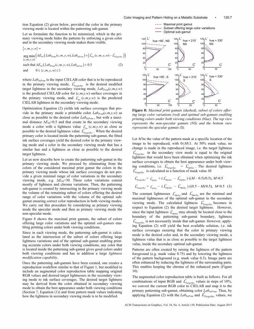
Figure 8 shows the maximal print gamuts, the subset of colors offering large color variations and the optimal sub-gamuts ena-bling printing colors under both viewing conditions.
Since in each viewing mode, the patterning sub-gamut is calcu-lated as the intersection of the subset of colors offering large lightness variations and of the optimal sub-gamut enabling print-ing accurate colors under both viewing conditions, any color that is located inside the patterning sub-gamut gives good colors under both viewing conditions and has in addition a large lightness modification capability.
Once the patterning sub-gamuts have been created, one creates a reproduction workflow similar to that of Figure 1, but modified to include an augmented color reproduction table mapping original RGB values and desired target lightnesses in the secondary view-ing mode to ink surface coverages. The desired target lightness may be derived from the color obtained in secondary viewing mode to obtain the best appearance under both viewing conditions (Section 7, Equation (1)) and from pattern mask values indicating how the lightness in secondary viewing mode is to be modified.
0 50 1000
20
40
60
80
100
120hue =90 , S°
0 50 1000
20
40
60
80
100
120
0 500
20
40
60
80
100
120 hue = 330°
S
0 500
20
40
60
80
100
120hue = 210°
NS
0 500
20
40
60
80
100
120hue = 210°
S
0 500
20
40
60
80
100
120hue = 330°
NS
C*
L*
C*
L*
C*
L*
C*
L*
C*
L*
C*
L*
Maximal print gamutSubset offering large color variationsOptimal sub-gamut
hue =90 , NS°
Figure 8: Maximal print gamuts (dashed), subset of colors offer-ing large color variations (red) and optimal sub-gamuts enabling printing colors under both viewing conditions (blue). The top view represents the non-specular gamuts (NS) and the bottom view represents the specular gamuts (S).
Let M be the value of the pattern mask at a specific location of the image to be reproduced, with 0≤M≤1. At 50% mask value, no change is made in the reproduced image, i.e. the target lightness
*TargetSecL in the secondary view mode is equal to the original
lightness that would have been obtained when optimizing the ink surface coverages to obtain the best appearance under both view-ing conditions, i.e. *
TargetSecL = *OptSecL . The desired lightness
*TargetSecL is calculated as a function of mask value M:
*TargetSecL = *
OptSecL + ( *MaxSecL *
OptSecL ) ((M 0.5)/0.5), M>0.5
*TargetSecL = *
OptSecL ( *OptSecL *
MinSecL ) ((0.5 M)/0.5), M<0.5 (3)
The constant lightnesses *MinSecL and *
MaxSecL are the minimal and maximal lightnesses of the optimal sub-gamut in the secondary viewing mode. The calculated lightness *
TargetSecL becomes in respect to Equation (2) the desired target lightness. However, since the input lightness *
OptSecL may already be located close to the boundary of the patterning sub-gamut boundary, lightness
*TargetSecL is not necessarily inside that sub-gamut. However, apply-
ing Equation (2) will yield the best available solution, i.e. ink surface coverages ensuring that the color in primary viewing mode is the desired color and, in the secondary viewing mode, a lightness value that is as close as possible to the target lightness value, inside the secondary optimal sub-gamut.
Patterns are often created by raising the lightness of the pattern foreground (e.g. mask value 0.75) and by lowering the lightness of the pattern background (e.g. mask value 0.3). Image parts are often enhanced by reducing the lightness of the surrounding parts. This enables keeping the chroma of the enhanced parts (Figure 10).
The augmented color reproduction table is built as follows. For all combinations of input RGB and *
TargetSecL values in steps of 10%, we convert the current RGB color to CIELAB and map it to the primary patterning sub-gamut, obtaining color LabInPrim. Then, by applying Equation (2) with the LabInPrim and
*TargetSecL values, we
Color Imaging and Pattern Hiding on a Metallic Substrate • 130:7
ACM Transactions on Graphics, Vol. 34, No. 4, Article 130, Publication Date: August 2015

obtain the corresponding optimal ink surface coverages and store them in the 4D augmented color reproduction table.
During the printing phase, in order to produce the color separa-tions yielding the desired pattern hiding effects, for each input RGB(x,y) image color and each pattern value M(x,y), we carry out the following operations. We first deduce the target light-ness *
TargetSecL as follows. We access the color reproduction table, obtain the optimal surface coverages of the inks as a function of the RGB values, predict the corresponding lightness *
OptSecL in the secondary viewing mode and modify it as specified by the pattern mask, according to Equation (3). Then, with the result-ing *
TargetSecL , the 4D augmented color reproduction table is ac-cessed and the corresponding ink surface coverages are obtained. The resulting cyan, magenta, yellow and white ink layers are halftoned and sent to the printer.
The consistency and accuracy of the present approach to hide patterns is validated by considering colors formed of all combina-tions of RGB intensities at 0%, 20%, 40%, 60%, 80% and 100%. For these RGB input intensities, we compute the difference be-tween colors predicted in primary viewing mode when changing the mask values from 50% to 25% (darkening) and from 50 to 75% (brightening). The results shown in Table 3 indicate that the color in primary viewing mode remains nearly constant.
Table 3: Color variations in primary mode when varying the lightness in secondary viewing mode.
ΔE94 Color variation in primary viewing mode for M={0.25|0.75} Mean 95% Max
Specular (25o:25o) 1.12 | 0.6 2.38|1.73 3.27|2.9
Non-specular (0o:45o) 0.96|0.66 2.19|2.11 3.82|5.03
10 Examples of hidden patterns, enhanced im-age parts and image alternations
Hiding and revealing text, graphics and grayscale vignettes or alternating between two grayscale images without significant ghosting effects is only possible under illumination and viewing angles that correspond either to specular or to non-specular view-ing conditions. When looking at the print in front of a window under daylight one may observe first the print under specular viewing conditions, and then by tilting the print vertically, ob-serve the print under non-specular viewing conditions.
Due to the limited dynamic range of the camera and of the repro-duction means, figures 9 to 12 show only an approximate view of the color prints on metal. For more dynamic views, see the sup-plementary videos.
Let us show an example of a message that is hidden in specular viewing mode and appears in the non-specular viewing mode (Figure 9). Tilting the printed sample vertically in front of a win-dow makes the text message appear and disappear (see the sup-plementary video). Thanks to this dynamic effect, the observing person remembers the text message.
For publicity purposes, it is often necessary to highlight the pres-ence of an object. Printing with variable amounts of white diffuse ink on a metallic substrate enables enhancing the presence of objects made of metal. For example, the presence of the metallic car shown in Figure 10a is enhanced in specular viewing mode by lowering the lightness of the background image (mask value of the background: 0.2).
Figure 9: Photograph of a color print with the message “English Green Tea” hidden in specular viewing mode (left, exposure 1/400 s, aperture f/14) and revealed in non-specular viewing mode (right, exposure 1/50 s, aperture f/14). The mask values are set to 0.75 for the message text parts and to 0.32 for the back-ground image. Therefore, in non-specular viewing mode, the text lightness is raised and the background image lightness is de-creased. Original photograph by Arne Nævra, with permission.
(a) (b) Figure 10: Photograph of an English car (a) appearing normally in non-specular viewing mode and (b) highlighted in specular viewing mode by reducing the lightness of the background (see the supplementary video). Exposure times are the same as in Figure 9. Courtesy: http://www.ambwallpapers.com/
As an example of a security document, we show an identity card specimen, with two instances of the face of the document holder, one instance appearing under non-specular viewing conditions and the second instance appearing under specular viewing condi-tions (Figure 11). When tilting the card in front of a window from non-specular to specular view, the face changes position from left to right.
Figure 11: Photograph of an identity card, with face appearing alternately, when tilting the card, (a) in non-specular and (b) in specular viewing conditions. Same aperture and exposure times as in Figure 9. See also the supplementary video.
The card is divided into two parts, the right part being viewed as colored background under primary non-specular viewing condi-tions and as the face image under specular viewing conditions and the left part being viewed as colored background under primary specular viewing condition and as the face image under non-specular viewing conditions. Since the background colors are the same in the left and right parts and despite the fact that the color separations are different, there is no visible boundary between
(a) (b)
130:8 • P. Pjanic et al.
ACM Transactions on Graphics, Vol. 34, No. 4, Article 130, Publication Date: August 2015

them. The target lightness *TargetSecL for each pixel in the secondary
viewing mode is formed as the lower lightness value between face and background. This enables blending the grayscale face image into the colored background. The lightnesses of the face image are obtained by converting the original achromatic RGB face image to CIELAB and by performing lightness mapping into the light-ness range of the optimal gamut in secondary viewing mode.
Since we are free to set a desired lightness in the secondary view-ing mode, the patterning mechanism can be used to have a first freely chosen grayscale image in the primary viewing mode and a second independently chosen grayscale image in the secondary viewing mode. Point “c” in Figure 7 shows that close to achro-matic colors in the primary viewing mode can be generated by a large variety of surface coverages of inks that can render nearly any other achromatic color in the secondary viewing mode.
As an illustration, a first grayscale image viewed in specular primary mode flips into a second grayscale image viewed in non-specular secondary mode (Figure 12).
(a) (b)
Figure 12: Photograph of the print showing (a) the first grayscale image (village) appearing in primary specular viewing mode and (b) the second grayscale image (Lena) appearing in secondary non-specular viewing mode. Same aperture and exposure times as in Figure 9. Gold hill and Lena images: courtesy http://homepages.cae.wisc.edu/~ece533/images/
The target lightnesses of the second grayscale image are obtained in the same manner as the lightnesses of the face image in the previous example. By accessing the augmented color reproduction table with the RGB values of the first grayscale image and the target lightness values of the second grayscale image, we obtain the optimal surface coverages of the inks.
11 Practical aspects and limitations
The incorporation of patterns within color images is limited by the available range of lightness variations, see Figure 7. This is due to the fact that the amount of white ink can only be increased up to 100% and decreased down to 0% and that as a compensation, similar amounts of CMY inks cannot be decreased by more than min(c,m,y) and cannot be increased by more than 1-max(c,m,y).
A pattern to be hidden in primary viewing mode, whose fore-ground has a higher lightness than the surrounding image parts (Figure 13, upright “T”) can be embedded into image parts that are relatively dark and have intermediate chroma values.
In image parts that have a high lightness and/or a high chroma, it may not be possible to create positive lightness differences and the pattern will vanish (regions α and γ in Figures 13a and 13b, respectively).
Alternately, one may create the pattern with lower lightnesses (Figure 13, upside down “T”). Creating patterns by lowering the lightness is possible in image regions that are not too dark. At low lightnesses, the pattern disappears (region β in Figure 13a). A solution that works correctly is to create patterns by raising the lightness of the pattern foreground and also lowering the lightness of the surrounding image or vice-versa. See the “English Green Tea” example in Figure 9.
Regarding the capability of alternating between a first and a sec-ond grayscale image, we show in Figure 14 that for any lightness 30< *
SpecL <80 in primary specular viewing conditions, and for any lightness 22< *
NonSpecL <80 in primary non-specular viewing condi-tions, one may generate a very large range of lightnesses in the secondary viewing conditions. For example, a non-specular light-ness of *
NonSpecL =40 may be realized by ink surface coverages yielding specular lightnesses between *
SpecL = 24 and *SpecL = 96,
see the dashed vertical bar in Figure 14. The intuitive explana-tions about the trade-off between amounts of white and of cyan, magenta and yellow inks given in Section 9 apply here as well.
a) Black-red-white: non-specular primary viewing mode
specular secondary viewing mode
b) Chromatic wedge, specular primary viewing mode
non-specular secondary viewing mode
Figure 13: Simulated color ramps with upright “T” pattern hav-ing an increased lightness and upside down “T” pattern with a reduced lightness. In wedge (a), the pattern is hidden in the non-specular viewing mode and in the wedge (b), the pattern is hidden in the specular viewing mode. In regions α and γ, increased light-ness patterns are not feasible. In region β, decreased lightness patterns are not feasible. The simulated color ramp images are created by predicting the CIELAB values from the obtained sur-face coverages of the inks and by converting them to sRGB image values.
20 40 60 80 10020
30
40
50
60
70
80
90
100
Non-specular viewing conditions
L*Spe
cula
rvi
ew
ing
cond
itio
ns
L*
w100w80
w60
w40
w20
w0w10cmy0
cmy20
cmy40
cmy60
cmy80
cmy100
Spec
NonSpec
Figure 14: Relationship between individual lightness values in the primary viewing mode (specular or non-specular) and the corresponding range of lightness values achievable in the secon-dary viewing mode, with related surface coverages of the inks. Achromatic colors are defined by equal surface coverages of the c,m,y inks (e.g. cmy40 means 40% surface coverages of c,m,y inks) and by the surface coverage of the white ink (e.g. w20 means 20% surface coverage of white ink).
12 Conclusions
In traditional printing systems, the gray-component replacement technique enables replacing similar amounts of cyan, magenta and yellow inks by some amounts of black ink. We discovered that in
Color Imaging and Pattern Hiding on a Metallic Substrate • 130:9
ACM Transactions on Graphics, Vol. 34, No. 4, Article 130, Publication Date: August 2015

the context of printing color images on a silver substrate, it is possible to compensate for an increase of diffuse white ink in specular viewing mode by a decrease of similar amounts of cyan, magenta and yellow inks and in non-specular mode by a corre-sponding increase of similar amounts of cyan, magenta and yel-low inks. This enables to keep a same color in one viewing mode and to vary the lightness in the other viewing mode
Thanks to optimization formula relying on accurate spectral pre-diction models to predict the color of given amounts of cyan, magenta, yellow and white inks either in specular or non-specular viewing modes, we created several color reproduction workflows. A first color reproduction workflow enables printing color images on a metallic substrate with high-chroma and bright color in specular viewing mode and with colors in non-specular viewing mode that look as good as those of a color image printed on paper. Applications are primarily artistic photography and decoration.
A second color reproduction workflow enables printing color images that in the secondary viewing mode differ in lightness from the color shown in the primary viewing mode. This enables hiding a text message into an image for example in specular view-ing mode and revealing it when the same printed image is shown in non-specular viewing mode. By modifying the lightness in the secondary viewing mode, one may also enhance specific image parts or create alternations between a first grayscale image viewed in the primary viewing mode and a second independent image viewed in the secondary viewing mode.
There are numerous applications. A color poster printed on metal may be placed at a position where the persons walking by observe first the poster under non-specular, then under specular and then again under non-specular viewing conditions. A message appear-ing only under specular reflection is surprising. The person will memorize that message and try to find an explanation why such a message appears and disappears, when viewed from different angles.
Fiscal stamps used in some countries may incorporate the coun-try’s color emblem in one viewing mode and the value of the stamp in the other viewing mode. A security label may incorpo-rate a colored metallic region on which “ORIGINAL” patterns appear only under specular reflection and a QR-code appears only under non specular reflection. Such a label would be very difficult to counterfeit. A wine bottle may show the view of a wine land-scape in one viewing mode and in addition the logo of its pro-ducer in the second viewing mode.
It would be interesting to verify if the present approach would also be suitable for a printer capable of printing metallic ink parti-cles on a white diffusing substrate. Printing with colored metallic inks such as silver, metallic cyan, metallic magenta, copper or gold may also allow creating interesting color variations when tilting the print from specular to non-specular observation condi-tions or vice-versa.
Acknowledgements We thank Dr Romain Rossier for having developed the initial version of the ink-spreading enhanced Cellular Yule-Nielsen Spectral Neugebauer model for transparent inks on paper. We also thank the Swiss National Science Foundation for its support (pro-ject 200021_143501).
References ALEXA, M, and MATUSIK, W. 2010. Reliefs as images. ACM Trans. on Graphics 29, 4 (July), 60:1–60:7.
BALASUBRAMANIAN, R. 1999. Optimization of the spectral Neuge-bauer model for printer characterization, Journal of Electronic Imaging 8, 2, 156-166.
BERMANO, A., BARAN, I., ALEXA, M., MATUSIK, W. 2012. Shad-owPix: Multiple images from self shadowing, Computer Graphics Forum 31, 593–602.
BERNARDINI, F., MITTLEMAN, J., RUSHMEIER, H., SILVA, C., and TAUBIN, G. 1999. The Ball-Pivoting Algorithm for Surface Re-construction, IEEE Trans. Vis. and Comp. Graph. 5, 4, 349-359.
DONG, Y., TONG X., PELLACINI, F., and GUO, B. 2012. Printing spatially-varying reflectance for reproducing HDR images, ACM Trans. Graph. 31, 4 (July), 40:1-40:7.
GLASNER, D., ZICKLER, T., LEVIN, A. 2014. A Reflectance Dis-play, ACM Trans. Graph. 33, 4, (July), 61:1-61:12.
HERSCH, R.D., COLLAUD, F., EMMEL, P. 2003. Reproducing color images with embedded metallic patterns, Proceedings SIGGRAPH, ACM Trans. Graph. 22, 3, 427-436.
LAN, Y., DONG, Y., PELLACINI, F., TONG, X. 2013. Bi-scale appearance fabrication. ACM Trans. Graph. 32, 4, 145:1-145:11.
LEVIN, A., GLASNER, D., XIONG, Y. DURAND, F., FREEMAN, W., MATUSIK, W., ZICKLER, T. 2013. Fabricating BRDFs at High Spatial Resolution Using Wave Optics, ACM Trans. Graph 32, 4,144:1-13
MALZBENDER, T., SAMADANI, R., SCHER, S., CRUME, A., DUNN, D., DAVIS, J. 2012. Printing reflectance functions, ACM Trans. on Graphics 31, 3, 20:1-20:11.
MATUSIK, W., AJDIN, B., GU, J., LAWRENCE, J., LENSCH, H. P. A., PELLACINI, F., RUSINKIEWICZ, S. 2009. Printing Spatially-Varying Reflectance, ACM Trans. Graph. 28, 5, 128:1-128:9.
MOROVIC, J., and LAMMENS, J. 2007. Color Management, in Colorimetry: Understanding the CIE system, (Ed. J. Schanda), Chapter 7, J. Wiley, 159–206.
MOROVIC, J., LUO, M. R. 2001. The fundamentals of gamut map-ping: A survey, Journal of Imaging Science and Technology 45, 3, 283–290.
MIKULA, M., CEPPAN, M., VASKO, K. 2003. Gloss and Goniocol-orimetry of Printed Materials. Color Research and Application 28, 5, 335-342.
PAPAS, M., HOUIT, T., NOWROUZEZAHRAI, D., GROSS, M., JAROSZ, W. 2012. The Magic Lens: Refractive Steganography, ACM Trans. Graph. 31, 6, Article No. 186:1-186:10.
PJANIC, P., HERSCH, R.D. 2013. Specular color imaging on a metallic substrate, In Proc. IS&T 21st Color Imaging Conference, 61-68.
ROSSIER, R., HERSCH, R.D. 2010. Introducing ink spreading within the cellular Yule-Nielsen modified Neugebauer model, In Proc. IS&T 18th Color Imaging Conference, 295-300.
SHARMA, G. 2003. Color fundamentals for digital imaging, in Digital Color Imaging Handbook (G. Sharma Ed.), Chapter 1, CRC Press, 1-114.
STOLLNITZ, E.J., OSTROMOUKHOV, V., SALESIN, D.H. 1998. Re-producing Color Images Using Custom Inks, Proceedings SIGGRAPH 98, Computer Graphics Proceedings, Annual Con-ference Series, 267-274.
WYSCECKI G., and STILES W.S., Color Science, J. Wiley, 1982.
YE, G., JOLLY, S., BOVE, V. M. Jr., DAI, Q., RASKAR, R., WETZSTEIN, G. 2014. Toward BxDF display using multilayer diffraction. ACM Trans. Graph. 33, 6, 191:1-191-14.
130:10 • P. Pjanic et al.
ACM Transactions on Graphics, Vol. 34, No. 4, Article 130, Publication Date: August 2015