Collision with tug due to loss of brake pressure, BAe Avro RJ85 Safety Board BAe... ·...
29
DUTCH SAFETY BOARD Collision with tug due to loss of brake pressure, BAe Avro RJ85
Transcript of Collision with tug due to loss of brake pressure, BAe Avro RJ85 Safety Board BAe... ·...
DUTCHSAFETY BOARD
Collision with tug due to loss of brake pressure, BAe Avro RJ85

Collision with tug due to loss of brake pressure, BAe Avro RJ85
The Hague, January 2019
The reports issued by the Dutch Safety Board are public.
All reports are also available on the Safety Board’s website: www.safetyboard.nl
Cover photo: R. McFadyen

- 3 -
The Dutch Safety Board
When accidents or disasters happen, the Dutch Safety Board investigates how it was possible for these to occur, with the aim of learning lessons for the future and, ultimately, improving safety in the Netherlands. The Safety Board is independent and is free to decide which incidents to investigate. In particular, it focuses on situations in which people’s personal safety is dependent on third parties, such as the government or companies. In certain cases the Board is under an obligation to carry out an investigation. Its investigations do not address issues of blame or liability.
Dutch Safety BoardChairman: T.H.J. Joustra
M.B.A. van AsseltS. Zouridis
Secretary Director: C.A.J.F. Verheij
Visiting address: Lange Voorhout 92514 EA The HagueThe Netherlands
Postal address: PO Box 954042509 CK The HagueThe Netherlands
Telephone: +31 (0)70 333 7000
Website: safetyboard.nlE-mail: [email protected]
N.B. This report is published in the English language with a separate Dutch summary. If there is a difference in interpretation between the report and the summary, the report text will prevail.

- 4 -
CONTENT
Abbreviations and Acronyms ..................................................................................... 5
General information ................................................................................................... 6
Summary .................................................................................................................... 7
1 Factual information ............................................................................................... 81.1 History of the event ............................................................................................... 81.2 Damage to aircraft................................................................................................. 81.3 Injuries ................................................................................................................... 91.4 The tug .................................................................................................................. 91.5 The aircraft ............................................................................................................ 91.6 Pushback procedures .......................................................................................... 121.7 Maintenance history ............................................................................................ 131.8 Previous flight ...................................................................................................... 131.9 Flight recorders ................................................................................................... 131.10 Actions following the event ................................................................................. 141.11 Meteorological situation ...................................................................................... 151.12 Radar data ........................................................................................................... 161.13 Aerodrome information ....................................................................................... 16
2 Analysis ................................................................................................................172.1 Classification and limitations ............................................................................... 172.2 Analysis of timeline in the QAR data ................................................................... 172.3 Similar elements during previous pushback ........................................................ 182.4 Normal procedures on stand and during pushback ........................................... 182.5 Brake setting with insufficient pressure ............................................................... 192.6 High rate of decay in brake pressure .................................................................. 202.7 Abrupt drop in brake pressure ............................................................................ 202.8 Forces leading to forward movement ................................................................. 212.9 Crew reaction to the movement .......................................................................... 212.10 Brake application after the collision .................................................................... 222.11 Safety risk during BAe 146/Avro RJ pushback .................................................... 22
3 Conclusion ........................................................................................................... 24
Appendix A. Brake system ...................................................................................... 25
Appendix B. Controls and warnings ........................................................................26
Appendix C. Draft report .........................................................................................27
- 5 -
ABBREVIATIONS AND ACRONYMS
AAIB Air Accidents Investigation Branch (United Kingdom)AAIU Air Accident Investigation Unit (Ireland)AIP Aeronautical information publicationAMM Aircraft maintenance manualAPU Auxiliary power unit
BAe British Aerospace
CVR Cockpit voice recorder
DSB Dutch Safety Board
EDP Engine driven pump
FCOM Flight crew operating manualFDR Flight data recorder
GOM Ground operations manualGPU Ground power unit
MWP Master warning panel
OEM Original equipment manufacturer
PTU Power transfer unit
QAR Quick access recorder
UTC Coordinated universal time

- 6 -
GENERAL INFORMATION
Identification number: 2015109
Classification: Serious incident
Date, time of occurrence: 15 December 2015, 19.451
Location of occurrence: Amsterdam Airport Schiphol, A8 taxiway
Registration: EI-RJT
Aircraft type: BAe Avro RJ85
Aircraft category: Four engine turbofan
Type of flight: Commercial air transport – passenger
Phase of operation: Pushback
Damage to aircraft: Substantial
Crew: Four (two flight crew, two cabin crew)
Passengers: 52
Injuries: None
Other damage: Slight damage to towbarless tug
Light conditions: Night
Figure 1: EI-RJT and towbarless tug after collision. (Source: Amsterdam Airport Schiphol)
1 Times in this report are in local time (UTC+1) unless stated otherwise.

- 7 -
SUMMARY
On 15 December 2015 a BAe Avro RJ85 registered EI-RJT was scheduled for a flight from Amsterdam Airport Schiphol to London City Airport. It was pushed back from gate D24 at Amsterdam Airport Schiphol. After the first engine was started, the tug driver lowered the aircraft’s nose gear. The Captain reported setting the parking brake and checking the brake pressure. The tug drove forward several metres to clear the starting engines. While starting up the fourth and last engine, the brake pressure suddenly dropped and the aircraft began to move forward. Over the next seconds, actions by the flight crew and the tug driver were unsuccessful in preventing a collision. The aircraft collided with the tug at 19.45 (local time) resulting in substantial damage to the lower front fuselage and slight damage to the tug. There were no injuries.
The investigation revealed a combination of causes. A fault in one or both parking brake motorised valves very likely caused an unusually high rate of pressure decay with the parking brake applied. The sudden drop in brake pressure that followed is very likely explained by depletion of the brake accumulator at its minimum supply pressure. Recorder data shows the initial brake pressure was insufficient, which contributed to the event. This irregularity cannot be explained by the evidence available to the investigation, and points to one or more additional technical or operational abnormalities. The manufacturer’s and operator’s procedures for engine start-up allow the event to occur by permitting use of the parking brake with all hydraulic pumps switched off.
A slight tailwind, a slight downward slope on the taxiway and all four engines running idle all contributed to overcoming what brake force may have remained, and thus moving the aircraft forward. Lighting conditions (astronomical night) likely delayed the crew’s perception of the movement.
Both the low initial brake pressure after pushback and the high rate of pressure decay were present one flight prior to the incident, four hours earlier on the same day. There is no indication that this behaviour was noticed and acted upon. The operator logged several occurrences of parking brake issues on other RJ85 aircraft in recent years which were solved by replacing a parking brake valve.
The safety risk related to this event is largely limited to the start-up phase of flight, where the parking brake may be applied with all three yellow system hydraulic pumps switched off. In this case, the accumulator is the sole source of brake pressure. The operational aspect of the investigation is limited by the amount of information available from the crew. No safety recommendations are issued.

- 8 -
1 FACTUAL INFORMATION
1.1 History of the event
The British Aerospace (BAe, the manufacturer) Avro RJ85 aircraft, registered as EI-RJT and operated by CityJet, was scheduled for an evening flight from Amsterdam Airport Schiphol (the aerodrome) to London City Airport on 15 December 2015. The aircraft was parked at gate D24. According to the Captain’s report the auxiliary power unit (APU) was running, the parking brake and the brakes operated normally, and the DC pump was used to top up the brake accumulator on stand. The aircraft was pushed back by a towbarless tug.2 During the movement, engine number 4 was started according to normal procedures.
After engine number 4 had stabilised, the tug driver stopped on taxiway A8. The Captain reported setting the parking brake and checking and announcing the brake pressure (between 2,000 and 3,000 psi). The tug driver lowered the aircraft’s nose gear and drove forward several metres. Engine numbers 3, 2 and 1 were started. Shortly after starting engine number 1, the tug driver was heard shouting and the crew realised the aircraft was rolling forwards. Both pilots attempted to brake without effect. The Captain reported seeing 0 psi brake pressure at this point with the parking brake still set. The aircraft hit the tug at 19.45. The passengers and cargo were unloaded one hour later. According to the Captain’s report the aircraft was found on a slight downward slope.
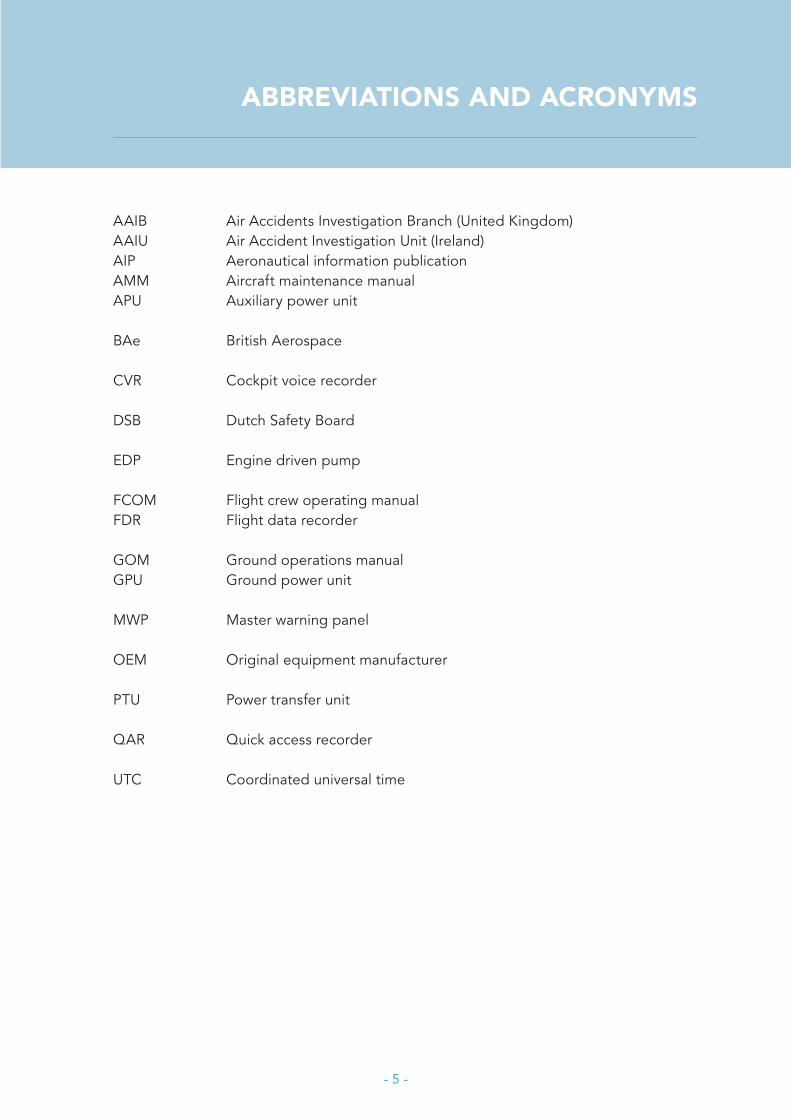
1.2 Damage to aircraft
The aircraft sustained substantial damage to the front fuselage skin, as can be seen in Figure 2. It was grounded for approximately one week to repair the damage. During this period, one of the parking brake valves was found to be operating intermittently. Following the fuselage repairs and replacement of the valve the aircraft returned to service.
2 A towbarless tug does not make use of a conventional towbar, connected to the aircraft’s nose gear. Instead it lifts up the nose gear for manoeuvring.
- 9 -
Figure 2: Damage to the right and left sides of the front fuselage. Note the location of the nose gear position
for reference. (Source: Amsterdam Airport Schiphol)
1.3 Injuries
No injuries were reported.
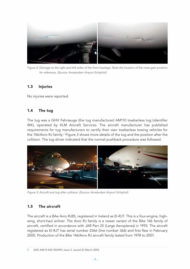
1.4 The tug
The tug was a GHH Fahrzeuge (the tug manufacturer) AM110 towbarless tug (identifier WK), operated by KLM Aircraft Services. The aircraft manufacturer has published requirements for tug manufacturers to certify their own towbarless towing vehicles for the 146/Avro RJ family.3 Figure 3 shows more details of the tug and the position after the collision. The tug driver indicated that the normal pushback procedure was followed.
Figure 3: Aircraft and tug after collision. (Source: Amsterdam Airport Schiphol)
1.5 The aircraft
The aircraft is a BAe Avro RJ85, registered in Ireland as EI-RJT. This is a four-engine, high-wing, short-haul airliner. The Avro RJ family is a newer variant of the BAe 146 family of aircraft, certified in accordance with JAR Part 25 (Large Aeroplanes) in 1993. The aircraft registered as EI-RJT has serial number 2366 (line number 366) and first flew in February 2000. Production of the BAe 146/Avro RJ aircraft family lasted from 1978 to 2001.
3 ADE-46B-R-460-003490, Issue 3, issued 22 March 2004.

- 10 -
1.5.1 The BAe 146/Avro RJ brake systemThe BAe 146/Avro RJ families of aircraft have two hydraulic systems: yellow (left) and green (right). For ground operations these systems are redundant except for two functions: only the yellow system powers the parking brake, and only the green system powers nose gear steering. An overview of the brake system is given in Appendix A. Information on these systems was derived from the manufacturer’s aircraft maintenance manual (AMM), flight crew operating manual (FCOM, vol. 1) and provided directly by the manufacturer.
Yellow and green system pressure are measured upstream of the brake system and shown on gauges on the hydraulic panel. This panel shows LO PRESS warnings when the respective pressures are below 2,500 psi. Hydraulic pressure over 3,500 psi triggers pressure relief valves.
Power sourcesThe yellow system can be pressurised by the engine number 2 engine driven pump (EDP) or the AC pump. Power for the AC pump can be provided by the Ground Power Unit (GPU), the APU or the generators on engines 1 and 4. No pump is needed for yellow braking4 if the brake accumulator has been charged. The green system can be powered by the engine number 3 EDP or the power transfer unit (PTU). The PTU is a hydraulic pump for the green system, which is mechanically powered by the yellow system without any fluid exchange when it is selected on.
A DC pump is available for emergency yellow hydraulics, which can also be used during towing. The DC pump can be powered by the APU or the aircraft battery. The DC pump selector has a spring-loaded switch labelled ON and a latched switch labelled BATT for continuous use.
Brake selectorThe RJ85 is fitted with a pushbutton selector for the green and yellow brake systems. An adjacent switch can be used to choose normal brakes or emergency yellow brakes, and a handle must be pulled to park on yellow. The emergency yellow selection overrides the normal selection, turns off the anti-skid system and turns on the DC pump continuously. The parking brake handle also overrides the normal selection.
Brake actionThe Captain’s (left) brake pedals are mechanically linked to the yellow brake system and the First Officer’s (right) are linked to the green brake system. One set of pedals does not move the other set. The control valves for the yellow and green systems are connected by two spring struts so each pilot can operate the other brake system. The brake control valves regulate the flow of brake fluid, proportional to pedal toe deflection. There are pressure sensors directly downstream of the brake control valves which separately indicate left and right brake pressure on the pressure gauges on the left instrument panel. This is the pressure at the pedals, which is not necessarily the same as the pressure at the brakes due to the anti-skid system.
4 In this report the terms ‘yellow brakes’ and ‘yellow braking’ refer to the brakes powered by the yellow hydraulic system.
- 11 -
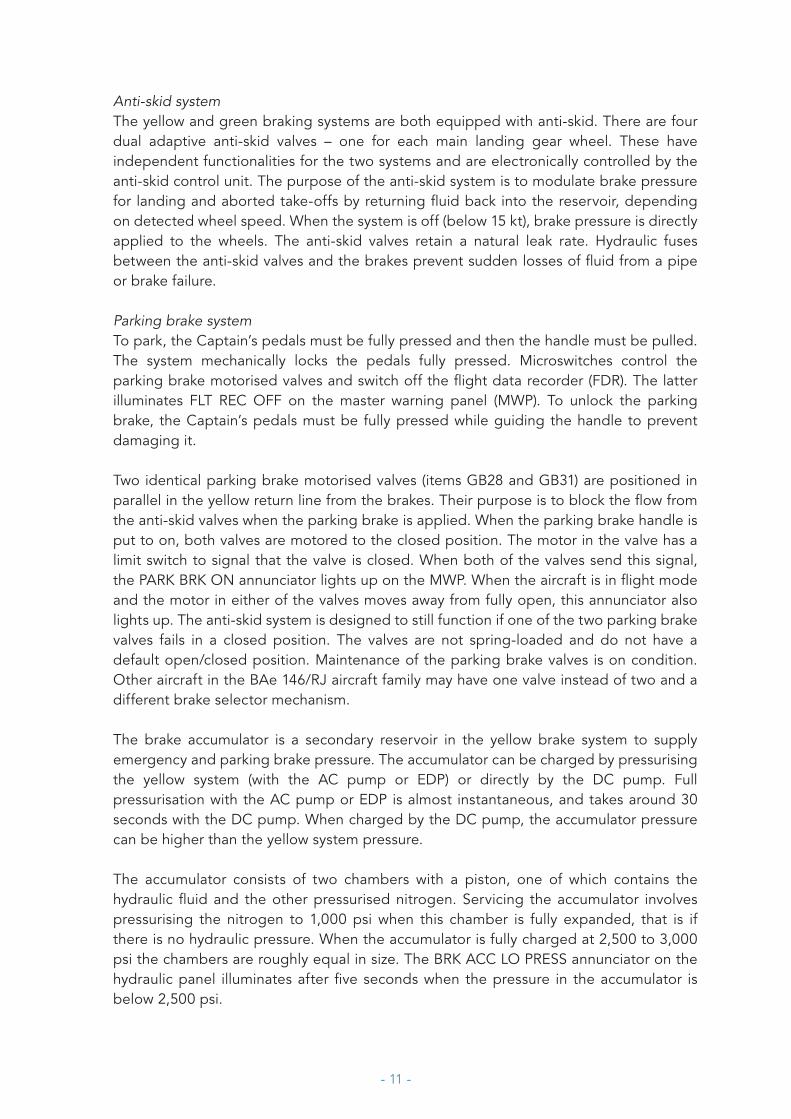
Anti-skid systemThe yellow and green braking systems are both equipped with anti-skid. There are four dual adaptive anti-skid valves – one for each main landing gear wheel. These have independent functionalities for the two systems and are electronically controlled by the anti-skid control unit. The purpose of the anti-skid system is to modulate brake pressure for landing and aborted take-offs by returning fluid back into the reservoir, depending on detected wheel speed. When the system is off (below 15 kt), brake pressure is directly applied to the wheels. The anti-skid valves retain a natural leak rate. Hydraulic fuses between the anti-skid valves and the brakes prevent sudden losses of fluid from a pipe or brake failure.
Parking brake systemTo park, the Captain’s pedals must be fully pressed and then the handle must be pulled. The system mechanically locks the pedals fully pressed. Microswitches control the parking brake motorised valves and switch off the flight data recorder (FDR). The latter illuminates FLT REC OFF on the master warning panel (MWP). To unlock the parking brake, the Captain’s pedals must be fully pressed while guiding the handle to prevent damaging it.
Two identical parking brake motorised valves (items GB28 and GB31) are positioned in parallel in the yellow return line from the brakes. Their purpose is to block the flow from the anti-skid valves when the parking brake is applied. When the parking brake handle is put to on, both valves are motored to the closed position. The motor in the valve has a limit switch to signal that the valve is closed. When both of the valves send this signal, the PARK BRK ON annunciator lights up on the MWP. When the aircraft is in flight mode and the motor in either of the valves moves away from fully open, this annunciator also lights up. The anti-skid system is designed to still function if one of the two parking brake valves fails in a closed position. The valves are not spring-loaded and do not have a default open/closed position. Maintenance of the parking brake valves is on condition. Other aircraft in the BAe 146/RJ aircraft family may have one valve instead of two and a different brake selector mechanism.
The brake accumulator is a secondary reservoir in the yellow brake system to supply emergency and parking brake pressure. The accumulator can be charged by pressurising the yellow system (with the AC pump or EDP) or directly by the DC pump. Full pressurisation with the AC pump or EDP is almost instantaneous, and takes around 30 seconds with the DC pump. When charged by the DC pump, the accumulator pressure can be higher than the yellow system pressure.
The accumulator consists of two chambers with a piston, one of which contains the hydraulic fluid and the other pressurised nitrogen. Servicing the accumulator involves pressurising the nitrogen to 1,000 psi when this chamber is fully expanded, that is if there is no hydraulic pressure. When the accumulator is fully charged at 2,500 to 3,000 psi the chambers are roughly equal in size. The BRK ACC LO PRESS annunciator on the hydraulic panel illuminates after five seconds when the pressure in the accumulator is below 2,500 psi.
- 12 -
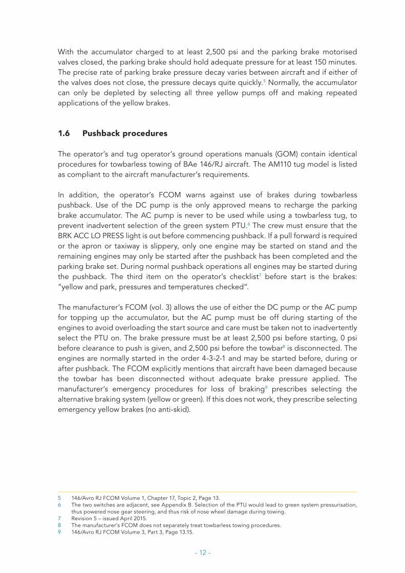
With the accumulator charged to at least 2,500 psi and the parking brake motorised valves closed, the parking brake should hold adequate pressure for at least 150 minutes. The precise rate of parking brake pressure decay varies between aircraft and if either of the valves does not close, the pressure decays quite quickly.5 Normally, the accumulator can only be depleted by selecting all three yellow pumps off and making repeated applications of the yellow brakes.
1.6 Pushback procedures
The operator’s and tug operator’s ground operations manuals (GOM) contain identical procedures for towbarless towing of BAe 146/RJ aircraft. The AM110 tug model is listed as compliant to the aircraft manufacturer’s requirements.
In addition, the operator’s FCOM warns against use of brakes during towbarless pushback. Use of the DC pump is the only approved means to recharge the parking brake accumulator. The AC pump is never to be used while using a towbarless tug, to prevent inadvertent selection of the green system PTU.6 The crew must ensure that the BRK ACC LO PRESS light is out before commencing pushback. If a pull forward is required or the apron or taxiway is slippery, only one engine may be started on stand and the remaining engines may only be started after the pushback has been completed and the parking brake set. During normal pushback operations all engines may be started during the pushback. The third item on the operator’s checklist7 before start is the brakes: “yellow and park, pressures and temperatures checked”.
The manufacturer’s FCOM (vol. 3) allows the use of either the DC pump or the AC pump for topping up the accumulator, but the AC pump must be off during starting of the engines to avoid overloading the start source and care must be taken not to inadvertently select the PTU on. The brake pressure must be at least 2,500 psi before starting, 0 psi before clearance to push is given, and 2,500 psi before the towbar8 is disconnected. The engines are normally started in the order 4-3-2-1 and may be started before, during or after pushback. The FCOM explicitly mentions that aircraft have been damaged because the towbar has been disconnected without adequate brake pressure applied. The manufacturer’s emergency procedures for loss of braking9 prescribes selecting the alternative braking system (yellow or green). If this does not work, they prescribe selecting emergency yellow brakes (no anti-skid).
5 146/Avro RJ FCOM Volume 1, Chapter 17, Topic 2, Page 13.6 The two switches are adjacent, see Appendix B. Selection of the PTU would lead to green system pressurisation,
thus powered nose gear steering, and thus risk of nose wheel damage during towing.7 Revision 5 – issued April 2015.8 The manufacturer’s FCOM does not separately treat towbarless towing procedures.9 146/Avro RJ FCOM Volume 3, Part 3, Page 13.15.

- 13 -
1.7 Maintenance history
Between 2008 and 2012 the operator logged parking brake issues with four different RJ85 aircraft. Two logs mention losing brake pressure in 30 to 40 seconds with the parking brake applied, which was mitigated by replacing a parking brake motorised valve. One log mentions the PARK BRK ON annunciator not switching on while the brake pressure was adequate, and one mentions a suspected pressure decay issue that was later deemed within limits.
In October 2014 an issue was logged on EI-RJT with the right-hand yellow brake pressure indicator showing 500 psi less than the left-hand indicator. The pressure transmitter was confirmed at fault and replaced. The last routine pressure decay rate test of the parking brake system before the event took place in May 2015 with no findings.
1.8 Previous flight
The operator provided flight data monitoring (FDM) data for the previous pushback on the day of the event, four hours earlier. Relevant parameters are shown in Figure 4.
Figure 4: FDM brake pressures and hydraulic pressure warning for the previous pushback on 15 December
2015. Time on the x-axis is in UTC.
1.9 Flight recorders
Cockpit voice recorder (CVR) data was not recovered for this event. It is unknown whether the FDR was recording during the event. The operator supplied FDM data, taken from the quick access recorder (QAR), shown in Figure 5. Six parameters from the brake system are recorded in the QAR. Right and left yellow and green brake pressure are measured just downstream of the pedals. Yellow and green low hydraulic pressure warnings are triggered upstream of the brake system below 2,500 psi. The BRK ACC LO PRESS and PARK BRK ON annunciators are not recorded, nor is the hydraulic system pressure (upstream of the brake system).

- 14 -
Figure 5: QAR data print-out: left and right yellow brake pressures, engine N1 speeds, heading and airframe
accelerations. Data with discrete markers are recorded less than once per second.
1.10 Actions following the event
While the aircraft was grounded for fuselage repairs, one of the parking brake motorised valves (GB28) was reportedly found to be working intermittently. It was removed and its replacement was tested satisfactory. The operator sent the valve to its original equipment manufacturer (OEM) for inspection and repair. The valve had accumulated 24,433 hours and 21,697 cycles since new. A strip inspection revealed that the gearbox, connector and motor were contaminated with oil, switch pins were worn out, the clutch seized,

- 15 -
the motor brushes worn out and the O-rings soft. The inspection report stated reason for failure is an intermittent motor. No troubleshooting or test results were logged with the suspect valve still installed, and the OEM inspection did not confirm the intermittent behaviour of the valve.
While still grounded, functional tests of the pedal and parking brake systems, a pressure decay test of the parking brake system, and troubleshooting of the brake system were carried out by the operator. All resulted in nil findings. After the fuselage repairs were completed, the aircraft returned to revenue service. The operator supplied graphs of FDM data for pushbacks over the next weeks after the event.
As part of the operator’s investigation the second parking brake motorised valve (GB31) was replaced in March 2016 and sent to the OEM for inspection. The clutch assembly was found to be contaminated and had to be replaced. The inspector’s stated reasons for failure are the faulty clutch, and incorrectly set up microswitches and hard stops. In August 2016, an anti-skid braking system integrity test and a detailed visual inspection of the anti-skid control valves for obvious defects were carried out. Both resulted in nil findings. In May 2017 another routine pressure decay test of the parking brake system was performed with nil findings. No further issues with the brake system on EI-RJT were reported.
1.11 Meteorological situation
The local METARs 20 minutes before and 10 minutes after the event were:
• EHAM 151825Z 12010KT 090V150 9000 FEW009 BKN040 08/07 Q1022 NOSIG• EHAM 151855Z 12009KT 9000 BKN038 08/07 Q1022 NOSIG
The event took place more than three hours after sunset, in astronomical night.
- 16 -
1.12 Radar data
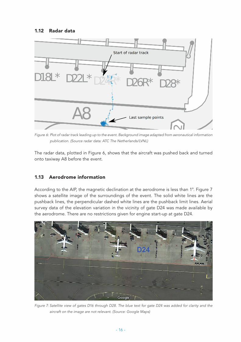
Figure 6: Plot of radar track leading up to the event. Background image adapted from aeronautical information
publication. (Source radar data: ATC The Netherlands/LVNL)
The radar data, plotted in Figure 6, shows that the aircraft was pushed back and turned onto taxiway A8 before the event.
1.13 Aerodrome information
According to the AIP, the magnetic declination at the aerodrome is less than 1°. Figure 7 shows a satellite image of the surroundings of the event. The solid white lines are the pushback lines, the perpendicular dashed white lines are the pushback limit lines. Aerial survey data of the elevation variation in the vicinity of gate D24 was made available by the aerodrome. There are no restrictions given for engine start-up at gate D24.
Figure 7: Satellite view of gates D16 through D28. The blue text for gate D24 was added for clarity and the
aircraft on the image are not relevant. (Source: Google Maps)
- 17 -
2 ANALYSIS
2.1 Classification and limitations
The damage to the front fuselage skin was substantial, leading to the aircraft being grounded for one week. The Dutch Safety Board classified the event as a serious incident due to the loss of control over the aircraft with risk of collision with other aircraft and/or persons. Under different circumstances, the consequences of the unintended aircraft movement could have been more severe.
The operator initially launched an internal investigation, for which no final report was drafted. Except from the Captain’s statements in the operator’s occurrence report (summarised in section 1.1), no other information from the flight crew was available to the Dutch Safety Board. Due to circumstances there was some delay in the investigation that made it difficult to obtain further information from the flight crew (the flight crew is no longer employed by the operator). This limited the possibilities to analyse the operational side of the event.
2.2 Analysis of timeline in the QAR data
The QAR data starts during the pushback manoeuvre (see Figure 5) as indicated by the heading change and accelerations. During the pushback movement, engine number 4 was started to idle thrust, corresponding to around 25% N1 rotation speed.
The data shows brake pressure being applied before engine number 3 was started at 19.43:58 hours. The yellow brake pressure upon application was around 1,500 psi left and right. The yellow brake pressures decayed at almost 6 psi/s for around 85 seconds (up to 19.45:23 hours) and then suddenly dropped to around 100 psi. The accuracy of the pressure sensor data in this range is unknown. During this time engines numbers 3, 2 and 1 were started to idle as well.
Directly after the pressure drop, the longitudinal acceleration became slightly positive for 8 seconds. The large negative longitudinal acceleration spike represents the collision with the tug at 19.45:31 hours. All four engines continued to run at idle. Around 40 seconds later (at 19.46:11 hours) the brake pressure increased to almost 3,000 psi and the low hydraulic pressure yellow (< 2,500 psi) warning stopped for a period of 5 seconds.

- 18 -
Following this peak at almost 3,000 psi, the brake pressure directly decayed again at a similar rate to before the impact up to about 19.48:30 hours and then stabilised just above 2,000 psi for the remainder of the recording. The last seconds of the recording show all engine rotation speeds dropping simultaneously, indicating deliberate engine shutdown by the crew.
There is no evidence of any errors in the available QAR data. The right brake pressure values are higher than the left pressure, which is consistent with all other RJ85 FDM figures provided by the operator and unlikely to be relevant to the investigation. The green brake system data shows no pressurisation, in accordance with procedures. Other parameters not shown in Figure 5 reveal no abnormal behaviour or warnings.
2.3 Similar elements during previous pushback
From the FDM data provided by the operator, the element(s) of an initial brake pressure of 1,500 psi and a pressure decay rate of 6 psi/s appear(s) to be present during at least one flight prior to the incident (see Figure 4). In the previous flight, further decay and/or a sudden drop in brake pressure appear to have been stopped by pressurisation through the AC pump or EDP.
The operator’s logs show two similar events on other RJ85 aircraft in recent years where the crew reported pressure decay on the parking brake and the issue was solved by replacing one of the parking brake valves. One event was logged of a crew reporting brake decay issues which were later deemed within limits. The two similar entries mention the pressure bleeding off within 30 to 40 seconds. It cannot be determined from the evidence if this is a faster or slower (and more or less noticeable) pressure decay rate than seen in this event.
2.4 Normal procedures on stand and during pushback
The Captain’s report states the APU was running, parking brake and brakes operated normally and the DC pump was used to top up the brake accumulator. No QAR data is available for this phase. There is no evidence of any abnormality on stand. However, the possibility cannot be ruled out that the brake accumulator was insufficiently pressurised in this phase.
The DC pump can be used in two modes: temporarily with the ON switch, or continuously with the BATT switch or emergency yellow brake selection. The operator forbids using the AC pump for towbarless procedures to prevent nose wheel damage, but it can technically be used on stand to pressurise the full yellow system if it is subsequently switched off during engine start-up. The Captain’s report and the relevant procedures mention ‘topping up’ the accumulator. The DC pump was likely used temporarily with the ON switch, in accordance with procedures.

- 19 -
The radar data confirms that no pull forward was involved in the movement. Based on the full set of METARs for 15 December 2015, there were no slippery conditions. In these circumstances the operator’s FCOM allows – but does not require – all four engines to be started on stand or while connected to the tug, and thus the AC pump and/or EDP to be switched on before disconnecting from the tug and setting the parking brake.
Based on the QAR data the engines were started in the order 4-3-2-1, starting with engine number 4 during the pushback and numbers 3-2-1 after setting the (parking) brake, in accordance with the manufacturer’s and operator’s FCOMs. If all engines had been started before or during the pushback, as was also allowed by procedures, the AC pump could have been enabled before setting the brake. If engine number 2 had been started before or during the pushback, its EDP could have been enabled before setting the brake. The manufacturer’s and operator’s prescribed procedures allowed the event to occur. The tug driver reported following the normal towbarless pushback procedure and the AM110 tug design was approved for use with RJ85 aircraft. There is no evidence of any operational abnormality in the pushback procedure or any technical abnormality in the tug itself.
2.5 Brake setting with insufficient pressure
The Captain reported checking the brake pressure after setting the parking brake, at between 2,000 and 3,000 psi. According to the manufacturer’s and operator’s procedures the pressure should be at least 2,500 psi and the manufacturer warns against disconnecting from the tug with inadequate brake pressure. The QAR data shows that the actual applied brake pressure was around 1,500 psi, which is inadequate.
The QAR data does not contain any information on whether or not the parking brake was (effectively) set. It is possible that the crew applied manual brake force instead of the parking brake, but this would require constant pedal deflection for 85 seconds which does not align with the Captain’s report.
The possibility that the pressure gauges indicated incorrect results cannot be fully excluded, as the right yellow pressure transmitter was replaced one year earlier after reportedly showing incorrect values. However, no further issues with the pressure gauges and transmitters or any other components in the (parking) brake system were reported following the event.
The cause of the 1,500 psi initially applied brake pressure cannot be determined from the evidence. The parking brake may not have been (effectively) set, the pressure gauges may have shown incorrect results, and/or the crew may have incorrectly read the pressures while topping up the accumulator or setting the (parking) brake. One or more additional technical or operational abnormalities must have been present before or during the event to explain the low brake pressure.

- 20 -
2.6 High rate of decay in brake pressure
Given the inspection reports, FDM graphs for subsequent flights, and logs of previous parking brake issues, the high rate of brake pressure decay was very likely caused by a faulty (GB28) parking brake motorised valve(s) due to wear. As stated in the OEM inspection report, oil contamination and/or worn out electrical contacts caused the faulty behaviour.
The role of the second valve (GB31) that was replaced two and a half months after the event cannot be ascertained, as the FDM graphs for subsequent flights show no significant pressure decay before the second valve was replaced. The inspection report does list a number of failures for this second valve which may or may not have affected its operations.
The parking brake valves are to be maintained on condition. The parking brake pressure decay rate is normally low enough to ensure adequate brake pressure for 150 minutes with all pumps disabled. The manufacturer’s FCOM and the operator’s logs indicate that a high rate of parking brake pressure decay from faulty parking brake valves has been experienced previously on this aircraft type.
A parking brake motorised valve that does not fully close should lead to a decay in yellow gauge brake pressure upon application of the parking brake, no illumination of PARK BRK ON, and illumination of BRK ACC LO PRESS once the accumulator pressure drops below 2500 psi. Based on the radar data available to the investigation, the aircraft was almost certainly in ground mode during the event so PARK BRK ON should not annunciate unless both valves were fully closed.
No details are available from the Captain’s report regarding the annunciators. It is very likely that the crew was occupied with the start-up procedures and possible that illumination of the BRK ACC LO PRESS annunciator was missed. Appendix B contains details on the location of the relevant controls, gauges and warnings. If the accumulator was not sufficiently pressurised on stand, the BRK ACC LO PRESS warning would have been on continuously. Assuming that the parking brake was effectively set, the QAR brake pressure data suggests that the BRK ACC LO PRESS warning was either continuously on, or that it illuminated before the start of the recording.
The maintenance and flight history before and after the incident provide no evidence of any other components in the hydraulic system being involved in this event. An overview of the system is shown in Appendix A.
2.7 Abrupt drop in brake pressure
The brake pressure drop was very likely caused by the pressure decaying until exhaustion of the brake accumulator, which delivers hydraulic fluid at a minimum of 1,000 psi when serviced. This pressure drop should lead to a visible change on the yellow brake pressure gauge but no change in the annunciators. This change can only be noticed by the flight crew by monitoring the brake pressure gauge.

- 21 -
2.8 Forces leading to forward movement
Figure 1, Figure 2 and Figure 3 show photographs taken after the collision. The aircraft moved along the pushback line after the brake pressure loss, as seen in the QAR heading data. The collision took place several metres in front of the pushback limit line with the tug’s docking mechanism raised. The damage to the aircraft’s front fuselage partially shows paint from the tug, which likely sustained slight damage from the collision.
The aircraft’s recorded true heading was around 65°. Based on the METARs, the wind likely had a velocity between 9 and 10 knots with a heading between 90° and 150° at the time of the incident. The proximity of the terminal building may have affected the actual local wind velocity and direction.
The Captain’s report mentions a slight downward slope of the taxiway. The aerial survey data supplied shows a marked downward slope on the northern side of taxiway A8, perpendicular to the apron. The data available is not precise enough to determine the exact downward slope along the path of the aircraft, but it is in the order of 1°.
The pressure drop as seen in the QAR recording coincides with the start-up of engine number 1 and the associated thrust of four engines running idle. None of the engines exceeded idle speeds in the QAR recording.
The local wind conditions, the slope of the taxiway, and four engines running idle contributed to the event. The resulting forces acted to overcome the brake force that may have been left. An in-depth analysis of the contributions of these forces was not undertaken as the cause of the movement was the loss of brake pressure.
2.9 Crew reaction to the movement
The incident took place at night and the Captain reported hearing the tug driver shouting. No information is available on the lighting conditions in the cockpit, but photographs indicate a moderate amount of ambient light on the taxiway. It is likely that these lighting conditions delayed the crew’s perception of the movement and that they had less than eight seconds to realise the situation and react. The longitudinal accelerations seen in the QAR data are minor and it cannot be determined whether these accelerations were noticeable.
The Captain reported that both pilots attempted to brake manually and that the parking brake was still set with 0 psi indicated brake pressure. As the parking brake mechanically locks the left (Captain’s) pedals, pressing the foot brakes with the parking brake applied can have one of two effects. If enough force is applied to the left brakes, the parking brake is unset. This would cause the parking brake lever to move inwards and make a loud sound if it is not guided by the crew. If insufficient force is applied to the left brakes or if the right brakes are used, the parking brake remains set. The crew’s actions during the movement cannot be determined with certainty but were ineffective overall in stopping the aircraft.

- 22 -
Pressing the foot brakes is a natural reaction to the unexpected movement during starting procedures. This was likely not the most effective reaction in this situation. If the AC pump or EDP (number 2) was switched on, pressurisation of the yellow system should be almost instantaneous and the brakes would likely have regained effectivity.
The emergency procedure in the manufacturer’s FCOM is not designed to manage this specific situation. Following it nonetheless would mean selecting green brakes via the pushbutton. As start-up procedures forbid pressurising the green system (to avoid nose wheel steering) and as the parking brake selector overrides the normal selector, this would almost certainly have had no effect. The next step would have been to select emergency yellow brakes. This would have resulted in switching off the anti-skid system and switching on the DC pump continuously. The DC pump takes around 30 seconds to fully pressurise the system while the movement took at most eight seconds. It appears that the emergency procedure could not have prevented the collision.
2.10 Brake application after the collision
Forty seconds after the collision the brake was applied with adequate pressure, almost 3,000 psi. The yellow system low pressure warning switched off for five seconds. This signifies that either the AC pump or the EDP was used to pressurise the system, as the DC pump does not pressurise the full system. The pump may have been switched off after several seconds, or the pressure decay may have been too rapid for the pump.
The brake pressure after the incident stabilised at around 2,000 psi three minutes after the collision. If all yellow pumps were off, the fault in the parking brake valve(s) may have (temporarily) discontinued. If one of the pumps was on, the hydraulic pressure decay and generation may have equalised.
At the end of the QAR recording the engine rotation speeds appear to drop, signifying engine shut-down. It is possible that the crew switched off the pump with shut-down in mind.
2.11 Safety risk during BAe 146/Avro RJ pushback
The event was most likely caused by a fault in one or both parking brake valves in the presence of one or more additional technical or operational abnormalities. The associated safety risk applies to situations where the parking brake is used with all three yellow hydraulic pumps switched off, for a period long enough that the brake pressure can decay to the point that the accumulator is depleted. This risk very likely applies to the entire family of BAe 146/Avro RJ aircraft due to the common design of the parking brake system. The investigation revealed no prior reports of a loss of control due to a faulty parking brake valve, while aircraft from this family have been operated for 40 years.
The manufacturer allows use of either the AC or DC pump to top up the brake accumulator. The parking brake may then be applied with all three pumps switched off depending on the relative timing of engine start-up, as appears to have occurred in this event.

- 23 -
During shut-down after a flight, the entire yellow and green hydraulic systems are normally fully pressurised from the two EDPs. The parking brake can then also be applied with all three pumps switched off. The initial volume and pressure of hydraulic fluid during shut-down procedures is normally much higher than during start-up procedures and wheel chocks are normally applied after taxiing. The risk of a loss of control is thus largely limited to the start-up phase of flight.
Due to the limitations of the investigation, and the limited associated safety risk, the Dutch Safety Board does not issue any safety recommendations.

- 24 -
3 CONCLUSION
During pushback the aircraft’s brake pressure suddenly dropped, leading to a forward movement. Actions by the flight crew and the tug driver were unsuccessful in preventing a collision between the aircraft and its tug.
This serious incident was partially caused by hydraulic pressure decay from a fault in one or both parking brake motorised valves, and subsequent depletion of the brake accumulator below its design pressure.
The following contributing factors were identified:
• The initially applied (parking) brake pressure was inadequate. Additional technical or operational abnormalities must have been present to explain this, but were not identified by the investigation.
• The manufacturer’s prescribed procedures allowed the incident to occur by permitting the parking brake to be set with all three yellow hydraulic pumps disabled.
• The operator’s prescribed procedures allowed the incident to occur by permitting the parking brake to be set with all three yellow hydraulic pumps disabled and by forbidding use of the AC pump while using a towbarless tug.
• When the brake pressure dropped, the aircraft started rolling forward along the pushback line. The local wind conditions, the slope of the taxiway, and thrust from four engines running idle contributed in overcoming what brake force may have remained.
The risk of a loss of control due to brake pressure loss is largely limited to the start-up phase, where the parking brake may be used with all three yellow hydraulic pumps switched off and the accumulator as sole source of hydraulic pressure.

- 25 -
APPENDIX A
BRAKE SYSTEM
Solid black line is green system, dashed line is yellow system, dotted line is return. (Source: BAe)

- 26 -
APPENDIX B
CONTROLS AND WARNINGS
Overview of all relevant controls and warnings. No specific situation is shown. (Sources: BAe and Dutch Safety
Board)

- 27 -
APPENDIX C
DRAFT REPORT
A draft version of this report has been presented to the parties involved in accordance with the Dutch Safety Board Act. These parties have been requested to check the report for any factual inaccuracies. The report has been presented to the following parties:
• Operator.• Air Accident Investigation Unit (AAIU), Republic of Ireland.• Manufacturer.• Air Accidents Investigation Branch (AAIB), United Kingdom.• European Aviation Safety Agency (EASA).
The Dutch Safety Board received a response from all parties.
The flight crew did not respond to invitations to check the draft report.
The Board has incorporated corrections of factual inaccuracies, additional details as well as editorial comments, where relevant. The relevant passages were amended accordingly in the final report.
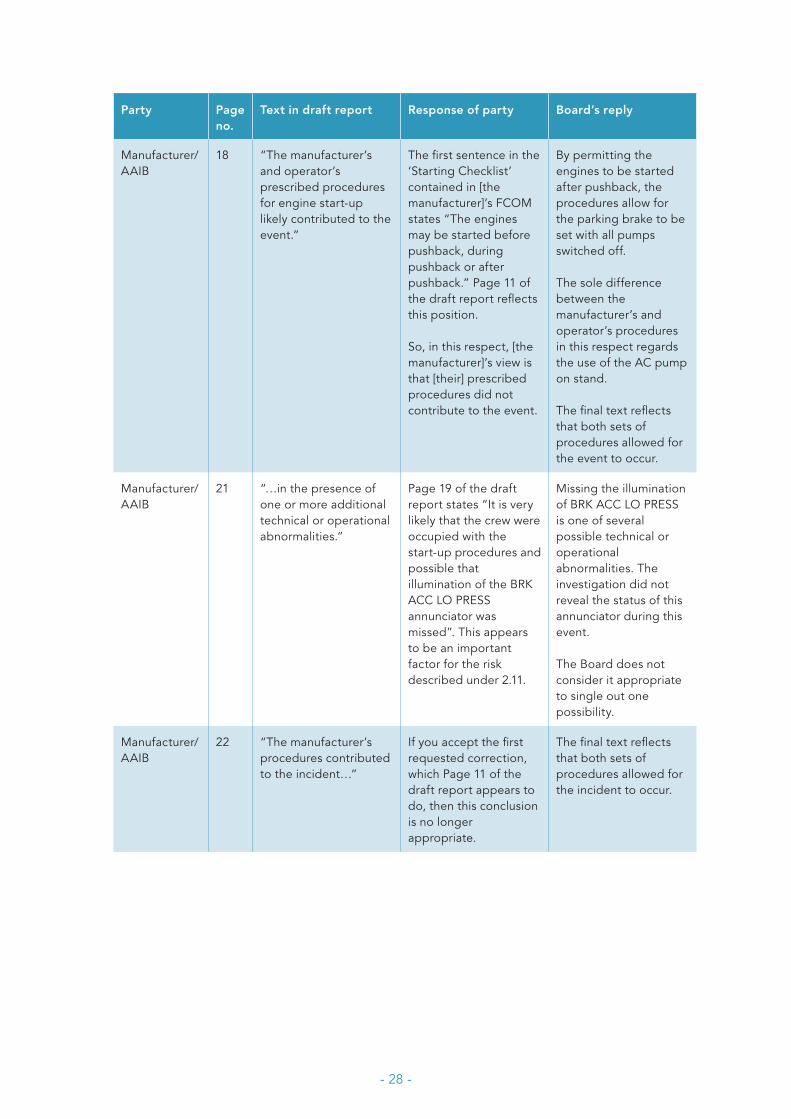
The Board replied to the responses that were not included in the report and included them in the table below (both the original responses and the Board’s replies). The page numbers listed in the table refer to the numbering of the draft report and no longer necessarily correspond to the numbering in the final report.
- 28 -
Party Page no.
Text in draft report Response of party Board’s reply
Manufacturer/AAIB
18 “The manufacturer’s and operator’s prescribed procedures for engine start-up likely contributed to the event.”
The first sentence in the ‘Starting Checklist’ contained in [the manufacturer]’s FCOM states “The engines may be started before pushback, during pushback or after pushback.” Page 11 of the draft report reflects this position.
So, in this respect, [the manufacturer]’s view is that [their] prescribed procedures did not contribute to the event.
By permitting the engines to be started after pushback, the procedures allow for the parking brake to be set with all pumps switched off.
The sole difference between the manufacturer’s and operator’s procedures in this respect regards the use of the AC pump on stand.
The final text reflects that both sets of procedures allowed for the event to occur.
Manufacturer/AAIB
21 “…in the presence of one or more additional technical or operational abnormalities.”
Page 19 of the draft report states “It is very likely that the crew were occupied with the start-up procedures and possible that illumination of the BRK ACC LO PRESS annunciator was missed”. This appears to be an important factor for the risk described under 2.11.
Missing the illumination of BRK ACC LO PRESS is one of several possible technical or operational abnormalities. The investigation did not reveal the status of this annunciator during this event.
The Board does not consider it appropriate to single out one possibility.
Manufacturer/AAIB
22 “The manufacturer’s procedures contributed to the incident…”
If you accept the first requested correction, which Page 11 of the draft report appears to do, then this conclusion is no longer appropriate.
The final text reflects that both sets of procedures allowed for the incident to occur.

DUTCHSAFETY BOARD
Visiting address Lange Voorhout 9 2514 EA The HagueT 070 333 70 00 F 070 333 70 77
Postal address PO Box 95404 2509 CK The Hague
www.safetyboard.nl