Collaborative Technology Alliance (CTA) Technology Alliance ... efficiency and fuel tolerance drive...
26
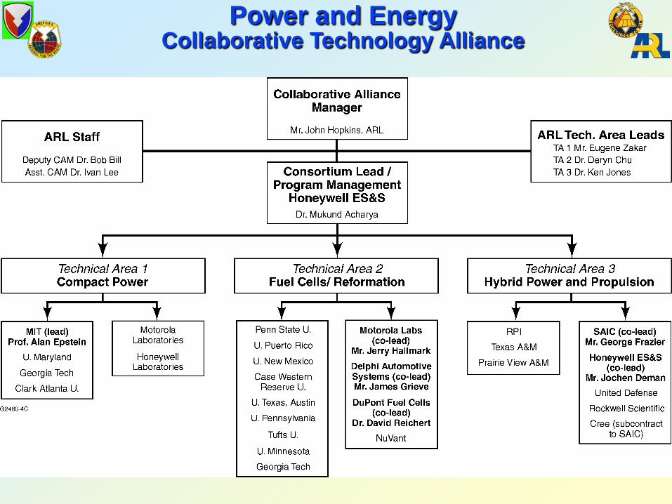
Mr. John Hopkins ARL Collaborative Alliance Manager Dr. Mukund Acharya Consortium Manager, Honeywell Engines, Systems & Services Collaborative Technology Alliance (CTA) Power & Energy (P&E)
-
Upload
hoangkhuong -
Category
Documents
-
view
217 -
download
2
Transcript of Collaborative Technology Alliance (CTA) Technology Alliance ... efficiency and fuel tolerance drive...

Mr. John HopkinsARL Collaborative Alliance Manager
Dr. Mukund AcharyaConsortium Manager, Honeywell Engines, Systems & Services
Collaborative Technology Alliance(CTA)
Power & Energy(P&E)

Objectives
Consortium Partners
Technical Areas Portable, Compact
Power Sources (Non-electrochemical)
Fuel Cells and Fuel Reformation
Hybrid Electric Propulsion and Power
Research and develop technologies that enable lightweight, compact power sources and highly power dense components that will significantly reduce the logistics burden, while increasing the survivability and lethality of the soldiers and systems of the highly mobile mounted and dismounted forces of the Future Army.
Power and EnergyCollaborative Technology Alliance
FY02 FY12SupportingTransformation Goals
Honeywell (lead) MIT Clark Atlanta Georgia Tech U of Maryland Motorola Labs U of New Mexico Case Western Reserve U DuPont Fuel Cells NuVant Systems U of Puerto Rico Penn State Univ Delphi Automotive Tufts Univ U of Minnesota U of Pennsylvania U of Texas – Austin SAIC United Defense LP Rensselear Polytechnic Rockwell Scientific
Power and EnergyCollaborative Technology Alliance

DoD and Commercial IndustryRequirements
Sec Min Hrs Days Month Years
1 G
10 M
100K
1K
10
0.1
0.001
Mission Length
Pow
er, W
atts
DoD Focus
Commercial Focus
X Directed Energy Weapons
X Ship DDX (Destroyer)
X Future Combat System, Mobility
X Cameras
X Satellites
X Warrior
X Cars
X Watches
X Laptops
X Home
X Tools
X Cell Phones

UnattendedGround
Sensors &Munitions
Power and Energy Taxonomy
Unit of Action
Responsive DeployableAgile and VersatileLethal Survivable
Sustainable
GroundManned & UnmannedMobile & Non-Mobile
SoldierFuture Force Warrior,
Land Warrior
AirManned & Unmanned
Aircraft
Hybrid Electric/
PropulsionEnvironment Management
Dynamic Armor
EM, ETC, DE
WeaponsActive
Protection C4 ISR Signature Management
Switches : Capacitors : Batteries : PowerConverters : Fuel Cells : Fuel Reformation
Thermal Management : Power Control: Power Generation
Operational Regimes
System of Systems
Platforms
Platform Applications
Technologies
UGS, Munitions,
Other
UnattendedGround
Sensors &Munitions
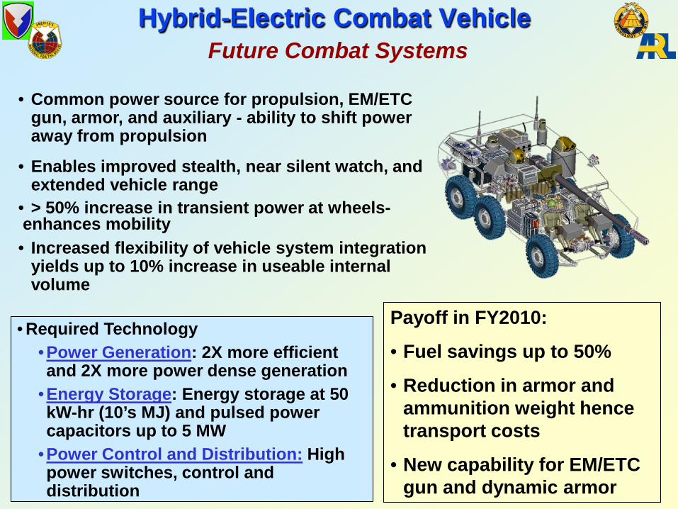
Hybrid-Electric Combat VehicleFuture Combat Systems
• Common power source for propulsion, EM/ETC gun, armor, and auxiliary - ability to shift power away from propulsion
• Enables improved stealth, near silent watch, and extended vehicle range
• > 50% increase in transient power at wheels-enhances mobility• Increased flexibility of vehicle system integration
yields up to 10% increase in useable internal volume
Payoff in FY2010:
• Fuel savings up to 50%
• Reduction in armor and ammunition weight hence transport costs
• New capability for EM/ETC gun and dynamic armor
• Required Technology•Power Generation: 2X more efficient and 2X more power dense generation
•Energy Storage: Energy storage at 50 kW-hr (10’s MJ) and pulsed power capacitors up to 5 MW
•Power Control and Distribution: High power switches, control and distribution

Required Technology:Energy Storage: Battery reactants with 3X increase in energy storage and 6X increase in power density, Novel liquid electrolyte reserve batteries, TRL 6, FY07.Power Control: Efficient chargers for two hour charge time and techniques to reduce power consumption by 50% in Soldier SystemsPower Generation: Logistic fuel reformation, Direct Methanol Fuel Cells, 750Wh/kg, 150oC, TRL6, FY06
Hybrid JP-8 fueled charger/rechargeable battery system capable of:
• eliminating non-rechargeable batteries• weighing 1/3 less than non-rechargeables• extending mission time per system up to 6X
Rechargeable batteries charged 2-3X faster
Power Management design tools reduce power consumption 2 to 5 times.
Cross-Service Critical ApplicationsWarrior Power
Return on InvestmentFY08 (1 Battalion, 96 Hour Mission):
4400 Disposable Batteries, $500,000, 8800 pounds
VERSUS
200 Gallons JP-8, Rechargeable Batteries, $400, 1600 pounds for fuel
DMFC Fuel Cell Demo FY06

P&E CTA Focused on ThreeTechnical Areas
1 10 100 1K 10k 100k 1M
POWER (Watts)
Compact Power Sources (Power MEMS)
Proton-Exchange Membrane (PEM) Fuel Cells
Logistics Fueled Solid Oxide Fuel Cells (SOFC)
Hybrid Electric Propulsion & Power
TA 1
TA 2
TA 3
Technical Area Power Levels Meet the Goals of Transformation for Soldier and Vehicular Loads

Portable Compact Power Sources
Electromagnetic Generator
Gas Turbine & Electrostatic Generator
Microfab Technology
Component Fabrication &MEMS Process Development

Technical Challenges: Improved yield from MEMS
fabrication of highly complex devices
Stable high speed rotation of silicon micro-rotors
Silicon structure strength at high temperatures
High performance levels from small-scale engine components
Recent Accomplishments:• Micro-turbocharger operated at high
speed (up to 480,000 rpm)• Micro-catalytic combustor
demonstrated• Magnetic generator device designed• Startup model for the gas turbine
engine developed
Turbine
Compressor
Gas Phase Combustion
Catalytic Combustorr
Portable Compact Power SourcesMEMS GAS TURBINE ENGINE
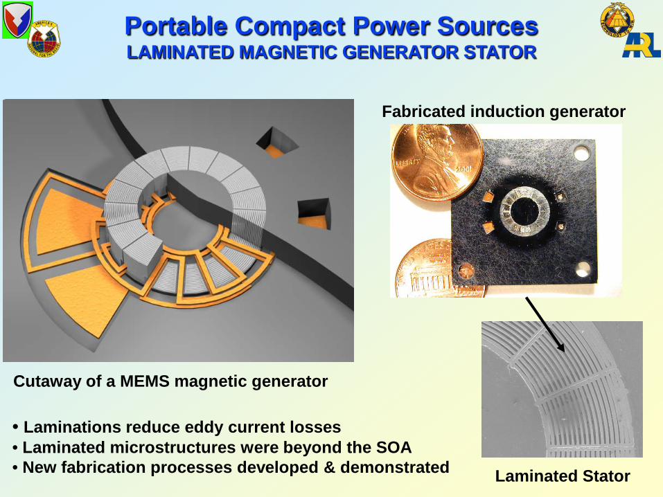
Portable Compact Power SourcesLAMINATED MAGNETIC GENERATOR STATOR
• Laminations reduce eddy current losses• Laminated microstructures were beyond the SOA• New fabrication processes developed & demonstrated
Fabricated induction generator
Cutaway of a MEMS magnetic generator
Laminated Stator

Portable Compact Power Sources3-D Profiles in Photoresist Film
• New micromachining processes – Continuously variable height silicon structure demonstrated– Grey-scale lithography makes 3D structures possible– Gas turbines use extensive 3D geometries– Process expands gas-turbine design space, improving performance

Fuel Cells and Fuel ReformationSOFC and Logistics Fuel Reformation
CatalyticPartial
Oxidation SOFC
anode
cathodeAir25oC
Fuel 600oC
600oC
800oC Exhaust150oC
Recuperator
Sulfur removal

Technical Challenges: Convert Logistic Fuels and
components to Hydrogen rich gas streams for SOFCs
Develop advanced catalysts, supports and materials for catalytic partial oxidation (CPOX)
Obtain operating parameters and that yield high conversion
Model reactions
Fuel Reformation: Advanced Catalysts
Recent Accomplishments:• Reformation of decane, hexadecane
and low-sulphur diesel fuel• Demonstrated fast lightoff of octane,
iso octane, decane and hexadecane • Determined limits of safe operation
without flames or explosions• Quantification and modeling of carbon
formation
Products
Air
Heating Tape
Insulation
Fuel Injector
Catalyst
Mixer
Working Catalyst

Technical Challenges: Trade-offs in power density, system
efficiency and fuel tolerance drive towards higher stack temperature. Metallic interconnects are a weak link in operating above 800 C.
Reforming, Desulfurization and Stack processes interact and must be configured into a system. Assessment of the CTA and other technical progress is needed to estimate system performance and to optimize the system for Army needs.
SOFC Stack and System Level Assessment
Recent Accomplishments:
• Development of screening tests for interconnect alloy evaluation.
• Development of Hysys models for system.
• Coupled proprietary version of stack electrochemical model to system model.
Logistics Fuels Fuel
Reformation SOFC
ElectricPower
Desulfurization
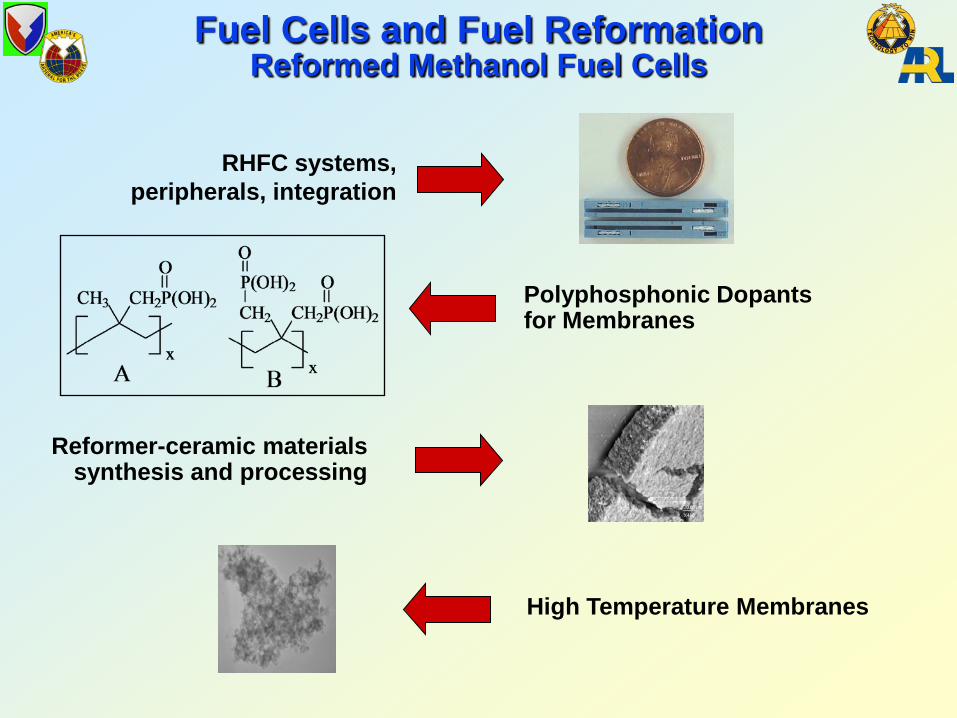
RHFC systems, peripherals, integration
Reformer-ceramic materials synthesis and processing
Fuel Cells and Fuel ReformationReformed Methanol Fuel Cells
Polyphosphonic Dopants for Membranes
High Temperature Membranes

Reformed Hydrogen Fuel Cell System
Technical Challenges:• Identify materials that are chemically
compatible for long term operation of elevated temperature fuel cell stack
• Develop low-pressure-drop 20W stack with optimal characteristics
• Develop 20W fuel processor for demonstration of principle
Recent Accomplishments:• Completed CFD model of the Gen 1
integrated fuel processor• Completed design and construction and
currently testing Gen 3.1 fuel processor (sized for 5W system)
• Demonstrated 2W proof of principle system running for >90hrs on mini-pumps with rudimentary control scheme
startup vaporizerreformer
combustorcombustor feed & exhaust
Outer dimensionsL = 49 mmW = 49 mmH = 5 mm

Technical Challenges: Develop methods of wall coating of
preformulated, industrial catalysts. Catalyst for Microchannel reformers
must provide low pressure drop and high activity
Demonstrate performance of wall coated reactor for hydrogen production
Catalyst coating should be adherent and stable for long term use
Reforming Catalyst in Porous Ceramic Support
Recent Accomplishments:• Analysis of Heat and Mass Transfer
Limitations in Packed Bed and Wall Coated Reformers
• 25 µm wall coat of catalyst demonstrated within microchannels
• Reactivity of wall coated catalyst exceeds that of packed bed
30.00 µm
4.1 mm
Water MeOHmixture
Vaporizer andSteam Reformer
Combustor(unreacted MeOH,H2)
FuelCellFuelCell
Stack
H2
electricity
2 mm
Catalyst coating,25 µm.

DMFC Catalyst DiscoveryOptical catalyst screening
Fuel Cells and Fuel ReformationDirect Methanol Fuel Cells
DMFC Catalysts,Low Methanol Crossover Membranes
DMFC MembranesMEAs
High throughput parallelScreening & testing
DMFC anode catalyst preparation& characterization
10 nm
PSU Pt/C
0.00 0.25 0.50 0.75 1.00
0.00
0.25
0.50
0.75
1.00 0.00
0.25
0.50
0.75
1.00
Ru (%)Pt
(%)
Os (%)
n
S O3H
m
R= H, tBu
S O2
H N
yx
O HO H

DMFC System Design
Objectives• Design and optimize a miniature 1W
DMFC system.• Model scale-up to larger systems to
determine overall system size, weight, and energy density.
Challenges• Integration and miniaturization of
system components.• Microfluidic design and processes
required to maintain the structural and electrical integrity of the fuel cell system
Accomplishments• 1W & 2W DMFC Systems designed, built
and tested.• > 1000 hour operation demonstrated for
1W prototype
Prototype 2W DMFC System

Basic Combat Hybrid Power System Architecture
POWER GENERATION
Diesel-Generator or Turbine-generator
ENERGYSTORAGE
Li-Ion Batteries and/or Flywheel
CONTINUOUS POWER CONDITIONING and
DISTRIBUTIONConverters, inverters,
power electronics, dc or ac buses, grounding,
shielding, fault control
MOBILITYTraction motors, EM suspension, steering
High Power Laser
ETCGun
High Power
Microwave
EMArmor
Other Pulsed Loads
LifeSupport
PULSED POWERPulse forming networks and/or pulsed flywheels,
THERMAL MANAGEMENT
Heat exchangers, fans, pumps, fluids
Temporary off-vehicle loads
(e.g. Soldier Power battery charging)
IC4 and Comms
Control System
Onboard Auxiliaries
100 kW to 5000 kW
50 kW to 1500 kW
50 kW to 1000 kW
1 kW to 50 kW
1 kW to 50 kW
250 kW to 1000 kW
250 kW to 1000 kW
Start
Main
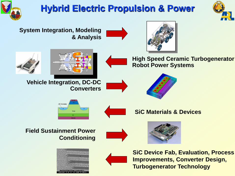
High Speed Ceramic TurbogeneratorRobot Power Systems
System Integration, Modeling& Analysis
Vehicle Integration, DC-DC Converters
Hybrid Electric Propulsion & Power
SiC Materials & Devices
Field Sustainment Power Conditioning
SiC Device Fab, Evaluation, Process Improvements, Converter Design, Turbogenerator Technology

Technical Challenges: Development and fabrication of high
temperature and high power density power electronics to meet aggressive space requirements on combat Hybrid Electric Vehicles (HEV) for FCS program.
Develop and test hybrid Si/SiC oil cooled 600 amp/1200 volt IGBT module and integrate into an oil cooled inverter.
Hybrid Electric Propulsion & PowerVehicle Power Conversion
Recent Accomplishments:• Designed new driver card for inverter to support
thermal and electrical testing.• Completed detail chip layout drawing for hybrid
module.• Completed bench test fixture design to
electrically and thermally test module.• Successfully developed backside and front side
metallization and soldering processes for soldering SiC SBD to cold plate.
• Successfully developed and tested soldering and wire bonding processes to be used on the module.
• Completed fabrication and assembly of 4 hybrid modules.
Hybrid IGBT Module
To
Coolant inlet temperature,
Ti
Conduction path
Molybdenum
Tortuous flow path
Spherical packed bed
Chip
Convection to coolant
Chip Temperature, Tc
Transitioned to CHPS SIL for Evaluation in Prototype FCS Inverter

Technical Challenges: Compact & Fuel-efficient primary
energy conversion subsystem High cycle temperatures Lubrication system limitations at
high speeds Direct-coupled high-speed
generators
Hybrid Electric Propulsion & PowerHigh-Speed Ceramic Turbogenerator
Recent Accomplishments:
Program ObjectiveDevelop and validate key technology enablers
Si3N4
EBC
• Initial screening experiments demonstrated that zirconia deposited on SiCN succesfully prevents the development of silica at this interface during oxidation.
• Initiated integration of start function in the generator for the gearless/oilless FPT engine configuration.
• Assessment of electrical machinery for the hybrid electrical drive system has been completed. Research on and development of disk (axial gap) type PM machines for both generating and motoring is recommended
Free Power Turbine
Specific Weight = 0.2 lb/hpSpecific Volume = 0.04 ft3/hp
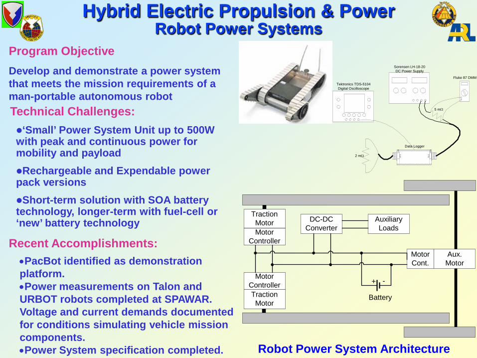
Technical Challenges:‘Small’ Power System Unit up to 500W with peak and continuous power for mobility and payloadRechargeable and Expendable power pack versionsShort-term solution with SOA battery technology, longer-term with fuel-cell or ‘new’ battery technology
Hybrid Electric Propulsion & PowerRobot Power Systems
Recent Accomplishments:
Program ObjectiveDevelop and demonstrate a power system that meets the mission requirements of a man-portable autonomous robot
•PacBot identified as demonstration platform. •Power measurements on Talon and URBOT robots completed at SPAWAR. Voltage and current demands documented for conditions simulating vehicle mission components.•Power System specification completed.
2 mΩ
5 mΩ
Fluke 87 DMM
Sorensen LH-18-20DC Power Supply
Tektronics TDS-5104Digital Oscilloscope
Data Logger
Aux.Motor
MotorCont.
AuxiliaryLoads
DC-DCConverter
MotorControllerTractionMotor
TractionMotorMotor
Controller
Battery
+ -
Robot Power System Architecture

Summary
• P&E CTA is part of the DoD and other agency programs to find solutions and efforts will be made to collaborate with other programs as appropriate• P&E CTA website for Government and Consortium access• Electric power demands continue to increase
Transformation for a Future Electric Force