COLLABORATIVE AIRCRAFT DESIGN USING AN · PDF filewithin the research project ......
12
1 Abstract Within aircraft design, the conceptual and preliminary phases ranging up to high fidelity multidisciplinary design optimization (MDO) increasingly feature an interdisciplinary character. To successfully develop novel high- performance aircraft and their components, effective collaboration among partners having different specialist backgrounds becomes a challenging task in the competitive environment of the future. Within the research project “Integrated and Distributed Engineering Services framework for MDO (IDEaliSM)”, a framework supporting this collaboration approach is under development. The envisioned geometry-centric development process requires an adequate IT supported integration environment, enabling efficient exploration of the interaction of design-driving physics. In addition, an extensive multi-fidelity parameterization strategy is required. This paper describes the main components required in a collaborative design process and proposes an architecture for collaborative design. An initial implementation of the geometry-centric approach and parameterization strategy is explained by means application to a design process the conceptual layout of a fighter configuration. 1 Introduction Aircraft design is an inherently multidisciplinary process, featuring strong interrelations among the design driving disciplines. Therefore, it is traditionally organized in by starting with assumptions and repeating the different design cycles several times with an increasing level of fidelity (see Fig. 1). At each design cycle pass, assumptions and previous results are verified and the aircraft design is adjusted based on the current level of information. This way, the requirements originating from the strongly interrelated disciplines are iteratively converged into a feasible design concept. Along this process, an increasing number of engineering routines are applied, reflecting the amount of disciplines considered in the design cycles. A major efficiency issue is imposed by the required manual work required to repeatedly run the different analyses in a coupled design environment. For an engineer, Fig. 1 Aircraft design, a highly iterative approach COLLABORATIVE AIRCRAFT DESIGN USING AN INTEGRATED AND DISTRIBUTED MULTIDISCIPLINARY PRODUCT DEVELOPMENT PROCESS Erwin Moerland 1 , Sebastian Deinert 2 , Fernaß Daoud 2 , Jochen Dornwald 2 , Björn Nagel 1 1 German Aerospace Center (DLR) - Institute of Air Transportation Systems, Hamburg 2 Airbus Defence & Space, Manching, Germany Keywords: Collaborative Engineering (CE), Multidisciplinary Design Optimisation (MDO), Common Parametric Aircraft Configuration Scheme (CPACS)
Transcript of COLLABORATIVE AIRCRAFT DESIGN USING AN · PDF filewithin the research project ......

1
Abstract
Within aircraft design, the conceptual and
preliminary phases ranging up to high fidelity
multidisciplinary design optimization (MDO)
increasingly feature an interdisciplinary
character. To successfully develop novel high-
performance aircraft and their components,
effective collaboration among partners having
different specialist backgrounds becomes a
challenging task in the competitive environment
of the future. Within the research project
“Integrated and Distributed Engineering
Services framework for MDO (IDEaliSM)”, a
framework supporting this collaboration
approach is under development. The envisioned
geometry-centric development process requires
an adequate IT supported integration
environment, enabling efficient exploration of
the interaction of design-driving physics. In
addition, an extensive multi-fidelity
parameterization strategy is required. This
paper describes the main components required
in a collaborative design process and proposes
an architecture for collaborative design. An
initial implementation of the geometry-centric
approach and parameterization strategy is
explained by means application to a design
process the conceptual layout of a fighter
configuration.
1 Introduction
Aircraft design is an inherently
multidisciplinary process, featuring strong
interrelations among the design driving
disciplines. Therefore, it is traditionally
organized in by starting with assumptions and
repeating the different design cycles several
times with an increasing level of fidelity (see
Fig. 1). At each design cycle pass, assumptions
and previous results are verified and the aircraft
design is adjusted based on the current level of
information. This way, the requirements
originating from the strongly interrelated
disciplines are iteratively converged into a
feasible design concept.
Along this process, an increasing number
of engineering routines are applied, reflecting
the amount of disciplines considered in the
design cycles. A major efficiency issue is
imposed by the required manual work required
to repeatedly run the different analyses in a
coupled design environment. For an engineer,
Fig. 1 Aircraft design, a highly iterative
approach
COLLABORATIVE AIRCRAFT DESIGN USING AN INTEGRATED AND DISTRIBUTED MULTIDISCIPLINARY PRODUCT
DEVELOPMENT PROCESS
Erwin Moerland1, Sebastian Deinert
2, Fernaß Daoud
2, Jochen Dornwald
2, Björn Nagel
1
1German Aerospace Center (DLR) - Institute of Air Transportation Systems, Hamburg
2Airbus Defence & Space, Manching, Germany
Keywords: Collaborative Engineering (CE), Multidisciplinary Design Optimisation (MDO),
Common Parametric Aircraft Configuration Scheme (CPACS)
E. MOERLAND, S. DEINERT, F. DAOUD, J. DORNWALD, B. NAGEL
2
this none-value-adding work mostly includes
preparation, understanding and reformatting
provided data to feed his individual disciplinary
analyses. This drastically reduces the available
time to creatively apply his knowledge to the
design problem at hand as well as a relatively
non-transparent way of working.
In the envisioned product development process,
transparent collaboration between engineers
located at multiple sites and even among
multiple companies will become part of the
daily routine. Through an increasing focus on
their core disciplines, engineers within the
process provide increasingly specific
engineering knowledge on an on-demand basis.
Within the collaboration framework
developed in the project IDEaliSM1 [1] and
proposed within this paper, this knowledge is
provided to the overall design process in the
form of engineering services.
engin
eeri
ng
serv
ice
a generically applicable engineering
routine, including its automated interface
to the collaboration framework. It features
a standardized exchange of input and
output data and ideally allows for batch-
execution.
These form an important part of the
‘knowledge core’ of each partner involved in
the product development process (see [2] on
knowledge acquisition). One of the main goals
of the services is to allow for effective re-use of
engineering knowledge spanning a multitude of
projects. Its application considerably reduces
the burden of performing repetitive tasks of an
explicit nature, thereby leaving more time for
creative thinking and design space exploration
[3].
Through automated execution of
engineering services in a streamlined
development process, the effectivity of the
aircraft design process is increased
considerably. Either more concept evaluations
1 The European project “Integrated & Distributed
Engineering Services Framework for MDO (IDEaliSM)”,
establishes an IT-based collaboration framework utilizing
the distributed engineering knowledge to drastically
increase the efficiency of product design processes.
within the same amount of time are viable, or
the duration of each design stage is drastically
reduced. Additionally, using the standardized
exchange of data, a more smooth connection
between the different design phases is
established by providing continuity between
methods, models and results.
By using a collaborative integration
framework the seamless interoperability of
methods, tools and people is established. It
enables distributed development teams to work
concurrently on the same products by
continuously sharing a single source of up-to-
date product data. Including multidisciplinary
design optimization (MDO) techniques further
improves the established process for early
aircraft design.
The paper is structured as follows: chapter
2 introduces the main components required
within a collaborative and distributed design
process. Chapter 3 introduces the formal
architecture for collaborative design, logically
structuring these components within the product
development process. An example application
to the process for the initial layout of a light /
medium fighter concept is provided in chapter
4. The paper ends with conclusions and an
outlook in the promising future of collaborative
aircraft design.
2 Towards an integrated collaborative and
distributed aircraft development process
One of main targets of the envisioned
development process is to allow for a higher
level of knowledge in early design stages. It is
especially these stages in the design process,
where decisions are of large influence on the
overall achievable performance of the aircraft
[4]. However, the decisions are mostly made
using a too limited design space due to practical
restrictions imposed by the complexity of the
design task. This can be overcome by
establishing a highly integrated and flexible
aircraft development process involving
interaction between all design driving
disciplines. The process is supported by
automated numerical analysis and optimisation,
both allowing for a massive extension of the
3
COLLABORATIVE AIRCRAFT DESIGN USING AN INTEGRATED AND
DISTRIBUTED MULTIDISCIPLINARY PRODUCT DEVELOPMENT PROCESS
design space and increasing the reliability of
decisions by invoking numerical analyses as
early as possible.
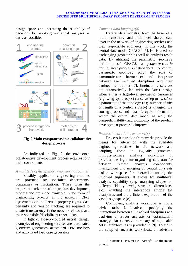
As indicated in Fig. 2, the envisioned
collaborative development process requires four
main components.
A multitude of disciplinary engineering routines
Flexibly applicable engineering routines
are provided by specialist departments,
companies or institutions. These form the
important backbone of the product development
process and are made available in the form of
engineering services in the network. Clear
agreements on intellectual property rights, data
certainty and version tracking are required to
create transparency in the network of tools and
the responsible (disciplinary) specialists.
In light of loosely-coupled aircraft design,
examples of engineering services are: automated
geometry generators, automated FEM meshers
and automated load case generators.
Common data language(s)
Central data model(s) form the basis of a
multidisciplinary and multilevel shared data
layer in the network of engineering services and
their responsible engineers. In this work, the
central data model CPACS2 [5], [6] is used for
exchanging geometric as well as analysis result
data. By utilizing the parametric geometry
definition of CPACS, a geometry-centric
development process is established. The central
parametric geometry plays the role of
communicator, harmoniser and integrator
between the involved disciplines and their
engineering routines [7]. Engineering services
are automatically fed with the latest design
when either a high-level geometric parameter
(e.g. wing span, aspect ratio, sweep or twist) or
a parameter of the topology (e.g. number of ribs
or length of a control surface) is changed. By
storing process and data life cycle information
within the central data model as well, the
comprehensibility and reusability of the product
development process is improved.
Process integration framework(s)
Process integration frameworks provide the
means for interaction with the available
engineering routines in the network and
coupling these in logically structured
multidisciplinary analysis workflows. It
provides the logic for organising data transfer
between remote analysis components,
management and merging of central data sets
and a workspace for interaction among the
involved engineers. It allows for multilevel
analysis capability (e.g. analysing shapes on
different fidelity levels, structural dimensions,
etc.) enabling the interaction among the
disciplines and the efficient exploration of the
vast design space [8].
Composing analysis workflows is not a
trivial task. It involves specifying the
interactions between all involved disciplines and
applying a proper analysis or optimization
strategy. An extensive summary of applicable
MDO architectures is provided in [9]. To aid in
the setup of analysis workflows, an advisory
2 Common Parametric Aircraft Configuration
Schema
Fig. 2 Main components in a collaborative
design process
engineering routines
structures
aero- dynamics
loads
engine
process integration framework
common data language
methods for collaboration
COM
COM
Power Equation LP Spool
Power Equ. HP Sp.
HPT Cooling
COM
COM
Power Equation LP Spool
Power Equ. HP Sp.
HPT Cooling
1 2
3 4
E. MOERLAND, S. DEINERT, F. DAOUD, J. DORNWALD, B. NAGEL
4
system is under development which assists in
choosing the most appropriate architecture for
the problem at hand [10]. In this work, the open-
source process integration software “Remote
Component Environment” (RCE) [11],
developed at DLR is used.
Methods for collaboration
Methods enabling effective cooperation of
and communication between teams of engineers
involved in the process play a key role in a
collaborative design project. Collaboration
between the involved teams in the process is a
large challenge, since most members are of
complementary specialization and share little
common expertise [12]. In order to cope with
the difficult inter-human relationships and to
consider the different stakeholders, their
characters and interests within the product
development process, formalized collaboration
methods are introduced. These methods aim at
creating a common understanding of the
problem and position of the engineering
routines within the design process.
Using the collaborative design components
in the development process as described above
provides the means to generate semi-automated
calculation and optimisation networks among all
partners involved in a design task. A stringent
requirement for the success of these analysis
networks is the structured matching of
organisational development processes among
the partners in an as less process-intrusive way
as possible.
3 An architecture for collaborative product
development
Within the IDEaliSM project, three
industrially relevant use-cases are considered:
1. Accelerated aircraft design, in which the
conceptual design of a fighter configuration
is conducted, corresponding requirements for
the vertical tail plane are forwarded to a tier-
1 supplier, which at its turn outsources the
design of the leading edge to a tier-2 supplier
within a short timeframe
2. Wire harness design, in which the detailed
wiring architecture of a transport aircraft is
designed in a dozen of working days
3. Automotive wiring design, in which the wire
harness for a cockpit is designed within
weeks instead of several months
The diversity in use-cases brings together a
group of engineers with a common interest in
semi-automated exploration of large design
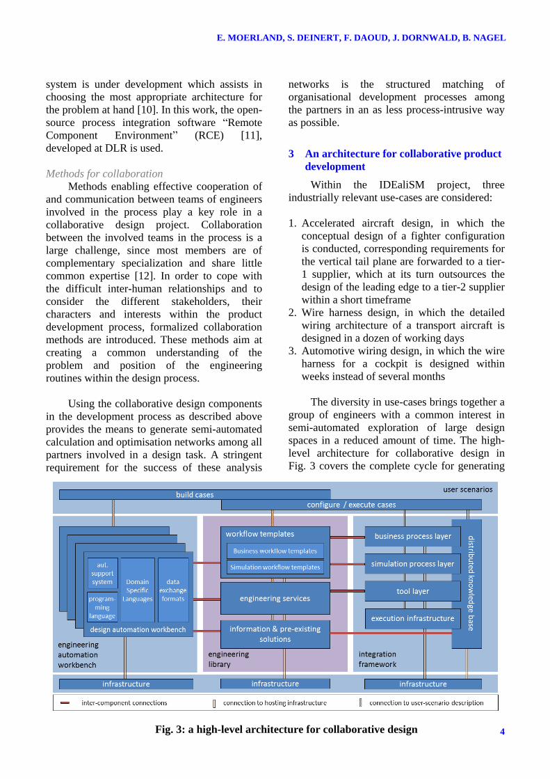
spaces in a reduced amount of time. The high-
level architecture for collaborative design in
Fig. 3 covers the complete cycle for generating
Fig. 3: a high-level architecture for collaborative design

5
COLLABORATIVE AIRCRAFT DESIGN USING AN INTEGRATED AND
DISTRIBUTED MULTIDISCIPLINARY PRODUCT DEVELOPMENT PROCESS
the intended design capabilities: the creation of
general analysis capabilities in a building phase,
through setting up the overall analysis logic in a
configuration phase to executing the analysis
and interpreting its result in an execution phase.
It formalizes the design process and is intended
to be generally applicable to all engineering
problems using collaborative and distributed
design as solution approach. Section 3.1
describes the components of the architecture;
section 3.2 provides an example application of a
build use-case.
3.1 Contents of the architecture for
collaborative design
The high-level architecture depicted in Fig.
3 contains five main components, described
hereafter.
An engineering library
Central to the framework is the engineering
library. By hosting the engineering services (as
described in the introduction of this paper) as
well as pre-existing solutions and workflow
templates, it forms the knowledge core of each
partner involved within the project. Its contents
are constantly enriched by performing design
projects of similar nature. The engineering
library contents reflects the central knowledge,
tools and services that each partner has available
to perform design studies in the domain of
application.
The envisioned product development
process starts by analysing the available
contents within the library. After identifying the
available and re-usable knowledge from the
library to answer a specific design question,
capability gaps might arise, triggering
developments using the automation workbench.
An engineering automation workbench
If increased knowledge is required to solve
a design question, developments using the
engineering automation workbench are
triggered. This workbench provides the
environment and all information required to
establish or adjust tools and information models.
At the basis of the automation workbench are
the automation support system the engineer is
familiar with, and the programming language in
which the development is performed. A design
language is used to create a domain specific
language, reflecting the explicit knowledge to
solve engineering problems within the experts’
domain of knowledge. To guarantee the proper
exchange of input and output data, the domain
specific language is encapsulated by a data
exchange format standardizing the
communication with other engineering library
content.
An integration framework
The sum of the available knowledge from
all involved partners is used within the
integration framework. The engineering library
contents are logically assembled within ready-
to-execute project templates. After fully
configuring these templates to the specifics of
the design question at hand, the integration
framework is used to perform the required
analyses within the execution phase of the
project. Analysis results as well as the (fully
configured) project templates are fed back to the
engineering library for long-term archival and
re-use in projects of a similar nature.
Within the integration framework, the
business process layer provides an interface to
the end user. It allows for the execution of
hybrid workflows in which both manual and
automated tasks are combined. The simulation
process layer allows for the execution of multi-
level and multi-disciplinary analysis workflows
and application of optimisation techniques.
Engineering services are made available to the
advanced integration framework using the tool
layer. Using the execution infrastructure layer,
the end-user defines the physical location in
which the analyses are performed, e.g.: on
computing clusters or by using cloud services.
Finally, a distributed knowledge base manages
the communication between the components
within and between each integration framework
layer. Using this data layer, a consistent and up-
to-date product and process description is
guaranteed during execution of the analysis
workflows.
An execution infrastructure
The infrastructure layer provides the
technical infrastructure required to host the

E. MOERLAND, S. DEINERT, F. DAOUD, J. DORNWALD, B. NAGEL
6
three aforementioned components. This
infrastructure typically consists of a network of
servers, (cluster) computers and cloud services,
providing the required capabilities to all
involved engineers within a project.
An extensive collection of user scenarios
Finally, the user scenarios layer formalizes
the interaction of engineers with the technical
components of the framework. It shows the
engineer which actions are to be taken during
design tasks and is thereby a means to provide
and save process knowledge. It formalizes the
tasks of all stakeholders within the collaboration
environment and provides an important means
to make the collaboration process transparent.
3.2 Application of a build-case using the
architecture for collaborative design:
connecting an analysis module to CPACS
As the most of the applied analysis tools do
not have a native interface to CPACS, a formal
procedure of connecting such tools to the data
format is defined in Fig. 4. For the modelling,
simplified ArchiMate by The Open Group [13],
[14] is used as descriptive language. It allows
for visual structuring of complex processes.
A connection to CPACS is generally
established by creating a small wrapper program
surrounding the analysis tool, circumventing
problems with the usually proprietary source
code. Using a suitable programming language
for the wrapper (either the same language as the
tool itself or a lightweight language such as
python), an input and an output channel need to
be defined. The pre-processor of the wrapper
selects the relevant data from the provided input
deck, validates its contents to the CPACS
Scheme and maps it to the native tool input
format. The post-processor has the opposite
function: it translates results from the native
output format to CPACS and provides non-
central output data if required (these might be
result plots, calculation meshes, etc.).
Supporting libraries with application
programming interfaces (API’s) to a multitude
of programming languages provide standard
query functions for content and geometry
handling in creating the wrapper program [15],
[16].
Once the data channels are available, the
execution logic can be implemented. To allow
for automated analyses, batch-execution
capability is pursued where possible. Once
tested for robustness, the complete package
consisting of the wrapped tool and applied
supporting libraries are saved in a standardized
folder structure and packaged as engineering
service within the engineering library.
Since using this method the source code of
a tool is decoupled from the wrapping approach,
flexible CPACS data interfaces can be
established to already existing tools. By
guaranteeing the integrity of the involved tools,
automatization strategies with low process-
intrusion are made possible.
Engineering Library Engineering Automation Workbench
user scenarios
AIF templates
engineering services
standards
business wf templates
simulation wf templates
tool wrapping workbench
‘build’ scenario: wrapping a tool to CPACS
data exchange
supporting librariesTIXIXML
interface
TIGLgeometry
library
Provide input channel
map data from CPACS
to tool language
select relevant data from CPACS
Provide output channel
map data from tool
language to CPACS
provide tool detailed results
CPACS
CPACS subselection, validated
input: tool specific
output: tool specific
enriched CPACS
detailed results(non central)
wrapped tool
toolexecution
data preprocessor
data postprocessor
validate input data
engineering service
implement execution
logic
CPACS Schema
Fig. 4 Implementation of a user-scenario
in the architecture for collaborative design:
wrapping a tool to CPACS

7
COLLABORATIVE AIRCRAFT DESIGN USING AN INTEGRATED AND
DISTRIBUTED MULTIDISCIPLINARY PRODUCT DEVELOPMENT PROCESS
4 Proof of concept: application to a fighter
aircraft design process
For the conceptual fighter configuration
part of the accelerated aircraft design use-case
(see chapter 3), the current process was
benchmarked and formalized using swim lane
diagrams. A high-level view of the first two
swim lanes is depicted in Fig. 5, serving as basis
for setting-up the accelerated design process.
Within the first swim lane, fast and flexible
methods for generating an initial parametric
geometry description fitting the operational and
technical requirements are needed. The second
swim lane relies on a set of engineering services
for the automated execution of physics-based
disciplinary analyses on low- to medium-fidelity
level. Using the multi-fidelity CPACS
parameterization scheme as basis, the geometry
and its physical properties are consolidated in
subsequent swim lanes, representing analyses of
increasing fidelity. The initial collaborative
design framework is set-up by creating and
coupling an engineering service for both swim
lane 1 and 2.
Section 4.1 discusses two approaches for
generating parametric geometries: a sketching
tool and rule-based system. Section 4.2 shows
the result of applying the build case as described
in section 3.2 by coupling low-level
aerodynamic analysis tools to CPACS. Section
4.3 shows an implementation of the engineering
services in a flexible analysis workflow,
allowing for automated designs of experiments
in distributed design networks.
4.1 Generating parametric geometry
descriptions: sketching and rule-based
layout
In this section, a sketching tool for creating an
initial design and an approach involving the
application of a set of empirical correlations and
design rules to the provided requirements is
described.
Sketching and manipulating a fighter aircraft
geometry
As the early conceptual design is a very
creative process, in which professional
experience can have large influence on the later
performance of the aircraft, an interactive
approach based on the in-house parametric
geometry tool Descartes is realized at Airbus
Defence and Space.
With a minimal set of geometric input
parameters (e.g. wing span, sweep angle etc.)
the different components of an aircraft can be
designed, offering direct visual feedback on the
chosen parameter values (see Fig. 6). Through
Fig. 5 swim lane representation of the
design process, engineering services depicted
in yellow boxes
Fig. 6 Sketching a wing planform using
Descartes, sliders allow the geometric
parameters to be adjusted
first swim lane
second swim lane
subsequent swim lanes

E. MOERLAND, S. DEINERT, F. DAOUD, J. DORNWALD, B. NAGEL
8
its native CPACS interface, a parametric
representation of this initial aircraft sketch is
automatically generated. The parametrization
can be used for parameter studies or even MDO
applications.
Using a rule-based system to generate
configuration layouts
At DLR, the conceptual design tool
VAMPzero is extended for application to fighter
configurations. Using object-oriented
programming, VAMPzeroF can respond to
different sets of operational and technical
requirements and topological assumptions (e.g.
canard on/off, single tail / double tail / v-tail,
aspect ratio, etc.), see Fig. 7. Over 500
parameters are estimated by means of empirical
correlations and response surface models from
pre-performed higher fidelity analyses. Point
performance is evaluated by means of
automated constraint diagram generation,
mission fuel determination by means of weight
fractions. Since the tool has runtimes in the
order of seconds, a very large amount of
configurations can be generated in short time.
Although a drawback is that parameters are
constrained by the validity range of the
underlying empirical correlations, the approach
allows engineers to ‘let the physics do the
talking’ and scan the complete design space to
find promising configurations.
The established parametric geometry in
CPACS is of sufficient detail for analyses in
swim lane 2. When applying to subsequent
swim lanes however, geometry refinement
strategies might be needed.
Since sketching and the direct application
of a rule-based system both have their pros and
cons, both approaches will be combined in
future work. Either a sketch is enriched using
empirics and standard design rules; or an initial
layout based on the set of design rules is
improved using sketching methods.
4.2 Automated aerodynamic analysis as
engineering service
At both Airbus Defence and DLR, engineering
services automating the execution of off-the-
shelf tools AVL for vortex-lattice analysis [17]
and Friction for friction drag estimation [18]
have been established. After applying all tasks
according to the scheme in Fig. 4, a
representative geometry was sketched using
Descartes and at both sites fed to the
engineering services using the process
integration software RCE. Since both processes
base on the same central geometry
parameterisation in CPACS, results from the
analyses should be the same. Fig. 8 shows a part
of the comparison that has been made. The
intention is not to get into the details of
explaining all differences between the curves,
but to show the importance of sharing the same
semantics between engineers involved in a
design task. The differences in drag coefficient
in the provided example stem from the actual
discretisation based on the central geometry to
the vortex-lattice input file as well as from
differences in defining parameters such as
characteristic lengths. In aircraft design, it is
common to use the mean aerodynamic chord of
a wing. The question is however, which wing
segments are involved? Is a wing projection to a
planar surface used, or the actual three-
dimensional wing? Differences in these kinds of
semantics can lead to significant differences in
analysis results. It is therefore of utmost
importance to always include the responsible
engineer(s) when interpreting analysis results of
the individual engineering services.
Fig. 7 flexible topology modeling in the
object-oriented conceptual design tool
VAMPzeroF
single tail v-tail double tail
canard

9
COLLABORATIVE AIRCRAFT DESIGN USING AN INTEGRATED AND
DISTRIBUTED MULTIDISCIPLINARY PRODUCT DEVELOPMENT PROCESS
Fig. 8 Comparison of total drag
coefficient results (friction + induced drag)
between Airbus Defence and DLR
4.3 Implementation of a flexible analysis
workflow for collaborative distributed
design
An initial implementation of an analysis
workflow in support of the first two swim lanes
of the design process is shown in Fig. 9. The
major goal is to support the design process by
automated analyses in a flexible network
environment. The engineering services in the
workflow are provided by combining
engineering library content from dedicated
remote servers owned by the involved design
teams. Thereby, the available knowledge is
shared within the distributed framework, while
the authority remains at the respective owners.
After connecting to the required
engineering libraries in the network, the
configuration phase of the process starts (see
chapter 3). The creation of a design structure
matrix (see e.g. [9], [12]) provides insight in the
dependencies between the involved engineering
services. Using the matrix, the services are put
in a logical execution order within their
respective swim lanes.
The engineering services described in the
previous sections are integrated in the workflow
in Fig. 9. Operational and technical
requirements are provided, topological
assumptions are made and the intended design
of experiments is set-up. The connection of the
design of experiments (DOE) component just
after the provision of requirements and
assumptions to the central data format, allows
these settings to be varied within the workflow.
Once the workflow is tested for robustness,
the execution phase of the process can start, by
executing the complete design of experiments
and triggering the required calculations at the
dedicated remote tool servers. The CPACS file
Fig. 9 Analysis workflow in RCE,
representing parts of the first swim lanes
within the product development process.
evaluation component
input provider
output writer
cpacs merger
engineering service
cpacs connection

E. MOERLAND, S. DEINERT, F. DAOUD, J. DORNWALD, B. NAGEL
10
is enriched with analysis results and available
for post-processing purposes after each
component execution throughout the complete
analysis workflow. The dashboard of RCE is
used as collaboration platform; each involved
engineer can connect to the integration
framework by logging in with a client instance.
The actual benefit of the capabilities of the
described integration framework emerges by
involving and coupling all relevant engineering
services and using the system to scan large
design spaces. Geometrical assumptions such as
wing aspect ratio, thickness and airfoil can be
varied for all topological options to find the
sweet spots in the vast design space. If enough
computational power is available, even the
provided requirements such as take-off field
length or action radius can be challenged by
showing their consequences using fully coupled
physics based calculations. The collaborative
integration framework paves the way for
coupling all required disciplines in the
envisioned product design process in an
efficient and effective way.
5 Conclusions
The aircraft design process gets increasingly
integrated and interdisciplinary. With the
collaboration framework architecture as
described in chapter 3, a structure is provided
for combining the identified technical
ingredients for collaborative and knowledge-
based design. It provides a basis for setting up
collaborative product development processes,
with at its centre workflows combining a
multitude of engineering services made
available through the engineering libraries of
the partners involved. Using these workflows,
design studies are orchestrated which can be
spread over multiple departments within a
single company or even across company
borders. Furthermore, the architecture allows for
application and ad-hoc exchange of engineering
services and analysis approaches. The
application of a common central data format
ensures the consistency of the system as well as
its applicability to a multitude of design
questions. An example application was shown
by generating initial geometries using either a
sketching tool or an empirics and design rule
based system. Both lead to an initial and
parametric description of a geometry being
interpretable by subsequent engineering services
in the product development process. During an
initial analysis run at Airbus and DLR, the
generation of aerodynamic performance maps
was undertaken and its results were compared.
The comparison has led to a common
understanding of the interpretation of the
involved analysis parameters. The established
workflows provide a solid basis for extension to
aircraft conceptual and preliminary design.
6 Outlook
In future work, more modules will be
incorporated within the analysis workflows at
both partners’ sites. The aim is to use the
collaboration framework setup to establish a
flexible system for performing tasks within the
conceptual design swim lanes of the aircraft
design cycle.
In parallel, methods will be developed for
increasing transparency during and after the
execution of analysis workflows. One of the
major points to be addressed is saving all
necessary process data along the product data.
Using this information, it can be deduced which
modules have been used to perform the analyses
within a data set and in which order these were
positioned and connected. Furthermore, by
providing provenance information, conclusions
can be drawn on which module or which
engineer has adjusted (parts of) the product data
and the reasoning behind this. Involving both
process and provenance information provides
valuable knowledge for communication
between involved engineers, ‘on-the-fly’
debugging and reasoning as well as a basis for
proper long term archival and retrieval of
analysis results.
By working out the complete conceptual
fighter design task, experiences in the setup of
the semi-automated calculation and optimisation
network among multiple teams of engineers are
gained and will be prioritized and highlighted in
future publications. An important and not to be
underestimated aspect in these experiences
concerns the non-technical issues arising in
implementing collaborative, knowledge-based
product development processes.

11
COLLABORATIVE AIRCRAFT DESIGN USING AN INTEGRATED AND
DISTRIBUTED MULTIDISCIPLINARY PRODUCT DEVELOPMENT PROCESS
References
[1] IDEaliSM consortium, “Integrated and Distributed
Engineering Services Framework for MDO
(IDEaliSM) - Project website,” 2016. [Online].
Available: http://www.idealism.eu/. [Accessed: 17-
Jul-2016].
[2] N. R. Milton, Knowledge Acquisition in Practice: A
Step-by-step Guide (Decision Engineering). 2007.
[3] G. La Rocca, “Knowledge based engineering
techniques to support aircraft design and
optimization,” Delft University of Technology,
Delft, The Netherlands, 2011.
[4] D. Schrage, T. Beltracchi, L. Burke, A. Dodd, L.
Niedling, and J. Sobieszczanski-Sobieski, “AIAA
Technical Committee on Multidisciplinary Design
Optimization - White Paper on Current State of the
Art,” 1991.
[5] C. Liersch and M. Hepperle, “A distributed toolbox
for multidisciplinary preliminary aircraft design,”
CEAS Aeronaut. J., vol. 2, no. 1, pp. 57–68, 2011.
[6] B. Nagel, D. Böhnke, V. Gollnick, P.
Schmollgruber, A. Rizzi, G. La Rocca, and J.
Alonso, “Communication in aircraft design: can we
establish a common language?,” 28th Int. Congr.
Aeronaut. Sci., 2012.
[7] R. Maierl, Ö. Petersson, and F. Daoud, “Automated
Creation Of Aeroelastic Optimization Models From
A Parameterized Geometry,” Int. Forum
Aeroelasticity Struct. Dyn. IFASD, 2013.
[8] S. Deinert, Ö. Petersson, and F. Daoud, “Aeroelastic
Tailoring Through Combined Sizing and Shape
Optimization Considering Induced Drag,” Int. Conf.
Eur. Aerosp. Soc. (CEAS), Linköping, Sweden, pp.
214–225, 2013.
[9] J. R. R. A. Martins and A. B. Lambe,
“Multidisciplinary Design Optimization: A Survey
of Architectures,” AIAA J., vol. 51, no. 9, pp. 2049–
2075, Sep. 2013.
[10] M. F. M. Hoogreef, R. D’Ippolito, R. Augustinus,
and G. La Rocca, “A multidisciplinary design
optimization advisory system for aircraft design,”
5th CEAS Air Sp. Conf. “Challenges Eur.
Aerospace”, Delft, Netherlands, 7-11 Sept. 2015, no.
41, pp. 1–15, 2015.
[11] German Aerospace Center - Simulation and
Software Technology - Distributed Systems and
Component Software, “RCE: Distributed,
Workflow-driven Integration Environment.”
[Online]. Available: http://www.rcenvironment.de.
[12] E. Moerland, R. G. Becker, and B. Nagel,
“Collaborative understanding of disciplinary
correlations using a low-fidelity physics-based
aerospace toolkit,” CEAS Aeronaut. J., vol. 6, no. 3,
pp. 441–454, 2015.
[13] The Open Group, “The ArchiMate® Enterprise
Architecture Modeling Language,” 2016. [Online].
Available:
http://www.opengroup.org/subjectareas/enterprise/ar
chimate-overview. [Accessed: 15-Jul-2016].
[14] H. van den Berg, H. Bosma, G. Dijk, H. van Drunen,
J. van Gijsen, F. Langeveld, J. Luijpers, T. Nguyen,
G. Oosting, R. Slagter, and E. Willemsz, ArchiMate
Made Practical. 2007.
[15] M. Siggel, T. Stollenwerk, and E. Al., “TIXI XML
interface,” 2016. [Online]. Available:
https://software.dlr.de/p/tixi/home/. [Accessed: 15-
Jul-2016].
[16] M. Siggel, T. Stollenwerk, and et al., “TIGL
Geometry Library,” 2016. [Online]. Available:
https://software.dlr.de/p/tigl/home/. [Accessed: 15-
Jul-2016].
[17] M. Drela and H. Youngren, “AVL.” [Online].
Available: http://web.mit.edu/drela/Public/web/avl/.
[Accessed: 20-Sep-2012].
[18] W. Mason and P. Buller, “Friction,” 2006. [Online].
Available:
http://www.dept.aoe.vt.edu/~mason/Mason_f/MRsof
t.html#SkinFriction. [Accessed: 05-Oct-2015].
Acknowledgements
The authors would like to express their gratitude to
the consortium members of the IDEaliSM project for their
valuable input and considerations in establishing the
framework architecture as described in chapter 3of this
paper. Special thanks go out to Stefan van der Elst and
Kevin van Hoogdalem of KE-works, Roberto d’Ippolito
of Noesis Solutions N.V., Tobie van den Berg of Fokker
Aerostructures B.V., and Maurice Hoogreef of Delft
University of Technology.
The research leading to the presented results was
performed within the European ITEA2 project “Integrated
& Distributed Engineering Services Framework for MDO
(IDEaliSM)”, as part of the EUREKA cluster programme.
The project is sponsored by the Federal Ministry of
Education and Research in Germany
Contact details
For further information on the topics described in this
paper, please send your inquiry to:
Erwin Moerland
German Aerospace Center (DLR)
Blohmstraße 20, 21079 Hamburg, Germany
Email: [email protected]
Telephone: +49 (0)531 295 3813

E. MOERLAND, S. DEINERT, F. DAOUD, J. DORNWALD, B. NAGEL
12
Copyright Statement
The authors confirm that they, and/or their company
or organization, hold copyright on all of the original
material included in this paper. The authors also
confirm that they have obtained permission, from
the copyright holder of any third party material
included in this paper, to publish it as part of their
paper. The authors confirm that they give
permission, or have obtained permission from the
copyright holder of this paper, for the publication
and distribution of this paper as part of the ICAS
proceedings or as individual off-prints from the
proceedings.