COLD AIR DRY MACHINING Part 2: SEM AND METALLOGRAPHIC ...
4
Edited by: S. Ekinović; S. Yalcin, J. Vivancos Journal of Trends in the Development of Machinery and Associated Technology Vol. 18, No. 1, 2014, ISSN 2303-4009 (online), p.p. 43-46 COLD AIR DRY MACHINING Part 2: SEM AND METALLOGRAPHIC ANALYSIS OF THE CHIP Sabahudin Ekinović 1 Edin Begović 1 Belma Fakić 2 Adisa Burić 2 Aida Čeliković 1 University of Zenica 1) Faculty of Mechanical Engineering 2) MI ''Kemal Kapetanović'' Zenica Bosnia and Herzegovina ABSRACT Dry machining and near-dry machining were developed as an alternative to flood and internal high- pressure coolant supply to reduce metal working fluids consuption. In dry machining, compressed air introduces into the cutting zone, while near-dry machining supplies very small quantities of lubricant into the cutting zone. Both these techniques have been introduced with the aim to reduce the use traditional coolant and lubricant. One of the many dry machining techniques is the usage of cooled compressed air. SEM and metallographic analysis of the chip during dry machining are presented in this paper. Machining tests were performed by turning of three grade of workpiece materijal: alloyed steel, aluminium bronze, and pure aluminium. Three ways of dry machining are performed: machining without the use of coolant and lubricant, cold air dry machining and with a cooling of workpiece before machining. Analysis of produced chips shows some advantages of dry machining, mainly in the process of chips segmentation, even in cases of machininig very ductile material. Keywords: Cold Air Dry Turning, Steel, Aluminium Bronze, Pure Aluminium 1. PREPARATION AND ANALYSIS OF THE CHIPS According to the experimental setup shown in Part 1, obtained chip was analyzed metallographically, and also by scanning electron microscopy. Results of these analysis during machining of alloyed steel Č.5432 (according to BAS standard) are shown in Figure 1. Workpiece hardness is 48 HRc. Tool used: CNMG 120404 SM AH 645. Other information concernig machining conditions are noted on Figure 1. Chips is continuous, with a pronounced jagged edge on the opposite side of the workpiece. For the different machining conditions (Figure 1.c, d, and e), the chip compression factors are 0.6, 0.8 and 0.4, respectively. It is interesting that with increasing cooling of the cutting zone, cracks on the outside of chips increased from 0.023 mm for machining without the use of coolant and lubricant, over the value of 0.028 mm for the cold air dry machining, up to a value of 0.04 mm when machining pre-cooled workpiece, Figure 1.c, d, and e. SEM photos (Figure 1.f, and g) very clearly show the lines of materijal flow during the deformation, arrow A, and crack on the outer side of the chips, arrow B (machining without use of coolant and lubricant). In conclusion it can be said that with the increase of cooling, makes it easy the formation of cracks in the chip.
Transcript of COLD AIR DRY MACHINING Part 2: SEM AND METALLOGRAPHIC ...

Edited by: S. Ekinović; S. Yalcin, J. Vivancos
Journal of Trends in the Development of Machinery
and Associated Technology
Vol. 18, No. 1, 2014, ISSN 2303-4009 (online), p.p. 43-46
COLD AIR DRY MACHINING
Part 2: SEM AND METALLOGRAPHIC ANALYSIS OF THE CHIP
Sabahudin Ekinović
1
Edin Begović1
Belma Fakić2
Adisa Burić2
Aida Čeliković1
University of Zenica 1)
Faculty of Mechanical Engineering 2)
MI ''Kemal Kapetanović''
Zenica
Bosnia and Herzegovina
ABSRACT Dry machining and near-dry machining were developed as an alternative to flood and internal high-
pressure coolant supply to reduce metal working fluids consuption. In dry machining, compressed air introduces into the cutting zone, while near-dry machining supplies very small quantities of lubricant
into the cutting zone. Both these techniques have been introduced with the aim to reduce the use
traditional coolant and lubricant. One of the many dry machining techniques is the usage of cooled compressed air.
SEM and metallographic analysis of the chip during dry machining are presented in this paper.
Machining tests were performed by turning of three grade of workpiece materijal: alloyed steel,
aluminium bronze, and pure aluminium. Three ways of dry machining are performed: machining without the use of coolant and lubricant, cold air dry machining and with a cooling of workpiece
before machining. Analysis of produced chips shows some advantages of dry machining, mainly in the
process of chips segmentation, even in cases of machininig very ductile material. Keywords: Cold Air Dry Turning, Steel, Aluminium Bronze, Pure Aluminium
1. PREPARATION AND ANALYSIS OF THE CHIPS According to the experimental setup shown in Part 1, obtained chip was analyzed metallographically,
and also by scanning electron microscopy. Results of these analysis during machining of alloyed steel
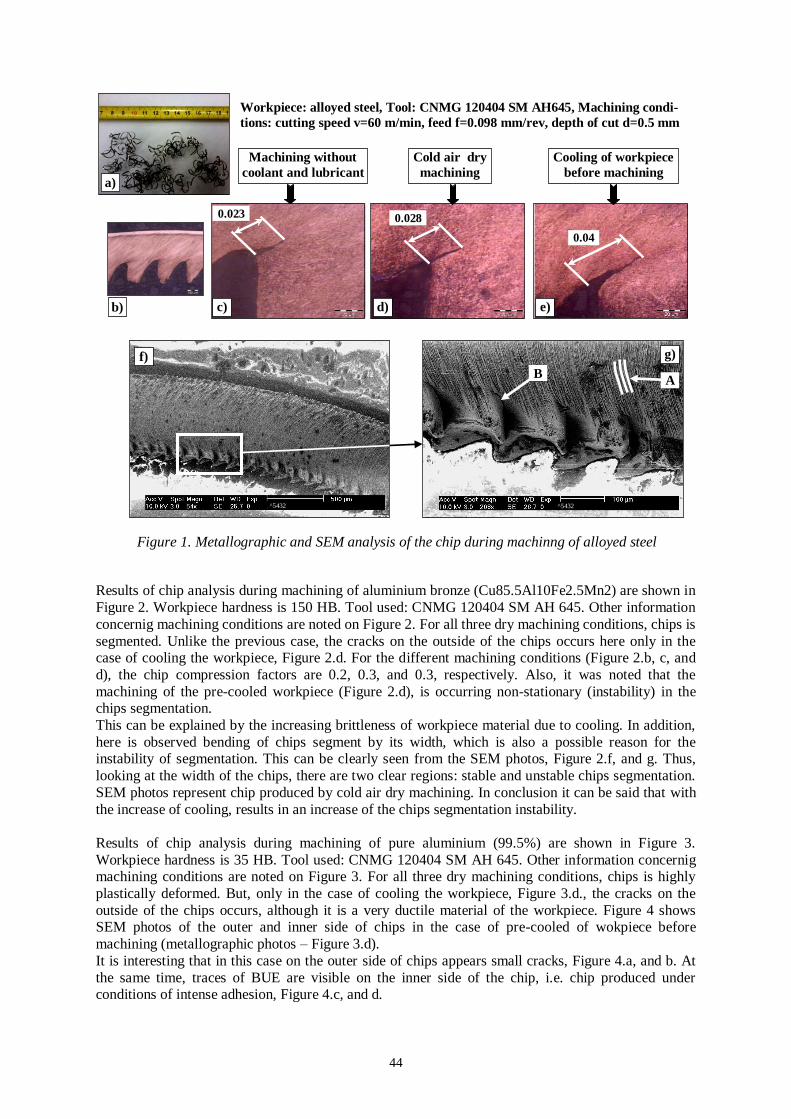
Č.5432 (according to BAS standard) are shown in Figure 1. Workpiece hardness is 48 HRc. Tool used: CNMG 120404 SM AH 645.
Other information concernig machining conditions are noted on Figure 1. Chips is continuous, with a
pronounced jagged edge on the opposite side of the workpiece. For the different machining conditions
(Figure 1.c, d, and e), the chip compression factors are 0.6, 0.8 and 0.4, respectively. It is interesting that with increasing cooling of the cutting zone, cracks on the outside of chips increased from 0.023
mm for machining without the use of coolant and lubricant, over the value of 0.028 mm for the cold
air dry machining, up to a value of 0.04 mm when machining pre-cooled workpiece, Figure 1.c, d, and e. SEM photos (Figure 1.f, and g) very clearly show the lines of materijal flow during the
deformation, arrow A, and crack on the outer side of the chips, arrow B (machining without use of
coolant and lubricant). In conclusion it can be said that with the increase of cooling, makes it easy the formation of cracks in the chip.
44
Results of chip analysis during machining of aluminium bronze (Cu85.5Al10Fe2.5Mn2) are shown in
Figure 2. Workpiece hardness is 150 HB. Tool used: CNMG 120404 SM AH 645. Other information
concernig machining conditions are noted on Figure 2. For all three dry machining conditions, chips is
segmented. Unlike the previous case, the cracks on the outside of the chips occurs here only in the case of cooling the workpiece, Figure 2.d. For the different machining conditions (Figure 2.b, c, and
d), the chip compression factors are 0.2, 0.3, and 0.3, respectively. Also, it was noted that the
machining of the pre-cooled workpiece (Figure 2.d), is occurring non-stationary (instability) in the chips segmentation.
This can be explained by the increasing brittleness of workpiece material due to cooling. In addition,
here is observed bending of chips segment by its width, which is also a possible reason for the instability of segmentation. This can be clearly seen from the SEM photos, Figure 2.f, and g. Thus,
looking at the width of the chips, there are two clear regions: stable and unstable chips segmentation.
SEM photos represent chip produced by cold air dry machining. In conclusion it can be said that with
the increase of cooling, results in an increase of the chips segmentation instability.
Results of chip analysis during machining of pure aluminium (99.5%) are shown in Figure 3.
Workpiece hardness is 35 HB. Tool used: CNMG 120404 SM AH 645. Other information concernig machining conditions are noted on Figure 3. For all three dry machining conditions, chips is highly
plastically deformed. But, only in the case of cooling the workpiece, Figure 3.d., the cracks on the
outside of the chips occurs, although it is a very ductile material of the workpiece. Figure 4 shows SEM photos of the outer and inner side of chips in the case of pre-cooled of wokpiece before
machining (metallographic photos – Figure 3.d).
It is interesting that in this case on the outer side of chips appears small cracks, Figure 4.a, and b. At
the same time, traces of BUE are visible on the inner side of the chip, i.e. chip produced under conditions of intense adhesion, Figure 4.c, and d.
0.023 0.028
0.04
^5432 ^5432
Workpiece: alloyed steel, Tool: CNMG 120404 SM AH645, Machining condi-
tions: cutting speed v=60 m/min, feed f=0.098 mm/rev, depth of cut d=0.5 mm
Machining without
coolant and lubricant
Cold air dry
machining
Cooling of workpiece
before machining
a)
b) c) d) e)
f) g)
A B
Figure 1. Metallographic and SEM analysis of the chip during machinng of alloyed steel

45
Machining without
coolant and lubricant
Cold air dry
machining
Cooling of workpiece
before machining
Workpiece: aluminium bronze, Tool: CNMG 120404 SM AH645, Machining
conditions: cutting speed v=85 m/min, feed f=0.2 mm/rev, depth of cut d=1 mm
a)
e) d) c) b)
Crack
Stable segmentation
Unstable segmentation
f) g)
Figure 2. Metallographic and SEM analysis of the chip during machinng of aluminium bronze
Machining without
coolant and lubricant
Cold air dry
machining
Cooling of workpiece
before machining
Workpiece: pure aluminium, Tool: CNMG 120404 SM AH645, Machining
conditions: cutting speed v=70 m/min, feed f=0.2 mm/rev, depth of cut d=1 mm
Crack
0.03
Figure 3. Metallographic analysis of the chip during machinng of pure aluminium (99.5%)
a)
b) c) d) e)
Figure 4. SEM analysis of the chip during machinng of pure aluminium (99.5%)
a) b)
Outer side of the chip Cracks

46
2. CONCLUSION
Results of SEM and metallographic analysis of the chip for three ways of dry turning of different
workpiece materijals: alloyed steel, aluminium bronze, and pure aluminium are presented. Based on the obtained results, the following conclusions can be made:
When using dry machining technology it is possible to affect the morphology of the chips,
One of the successful ways of dry machining is the use of cooled compressed air,
For a three different workpiece material, alloyed steel, aluminum bronze and pure aluminum, the
use of cooling the cutting zone, or at pre-cooled workpiece, chips morphology changes in all tested workpieces material,
Formation of cracks on the outher side of the chip appears always, even in the case of pure
aluminium machining.
3. REFERENCES [1] Kopač, J., Pusavec, F.: Concept of Sustainable Machining Processes, Proceedings of 13th International
Research/Expert Conference „Trends in the Development of Machinery and Associated Technology“,
TMT2009, Hammamet, Tunisia, 2009, pp.I-1-I-7.,
[2] Weinert, K., Inasaki, I., Sutherland, J.W., Wakabayashi, T.: Dry machining and minimum quantity
lubrication, CIRP Annals, (53), No.2, 2004, 511-537,.
[3] Ekinović, S., Begović, E., Ekinović, E., Fakić, B.: Cutting Forces and Chip Shape in MQL Machining of
Aluminium Bronze, Journal of Trends in the Development of Machinery and Associated Technology,
Vol.17., No.1., 2013, pp. 17-20.,
[4] Jozić, S., Celent, L., Bajić, D.: Achievement of Green Manufacturing using Alternative Types of Cooling
in Machining Processes, Proceedings of the 4th International Symposium on Sustainable Development,
ISSD2013, GRE-1396, 2013. p.7.,
[5] Asthakov, V.P.: Tribology of Metal Cutting, Elsevier, London, 2006. [6] Ekinović, S., Begović, E., Lušija, A.: MQL Machining – Oil on Water Droplet System, Proceedings of the
4th International Symposium on Sustainable Development, ISSD2013, GRE-1240, 2013. p.8.
[7] Kolcke, F., Eisenblaetter, G.: Dry cutting, CIRP Annals, (46), No.2, 1997, pp. 519-526.
Traces of
BUE
c) d)
Figure 4. Continuation – The end
Inner side of the chip