Coherent Accelerator Processor Interface User's … Accelerator Processor Interface User’s Manual...
101
Coherent Accelerator Processor Interface User’s Manual Advance Version 1.2 29 January 2015 Title Page
Transcript of Coherent Accelerator Processor Interface User's … Accelerator Processor Interface User’s Manual...
Coherent Accelerator Processor Interface
User’s Manual
AdvanceVersion 1.229 January 2015
Title Page

®
Copyright and Disclaimer© Copyright International Business Machines Corporation 2014, 2015
Printed in the United States of America January 2015
IBM, the IBM logo, and ibm.com are trademarks or registered trademarks of International Business Machines Corp., registered in many jurisdictions worldwide. Other product and service names might be trademarks of IBM or other compa-nies. A current list of IBM trademarks is available on the Web at “Copyright and trademark information” at www.ibm.com/legal/copytrade.shtml.
Other company, product, and service names may be trademarks or service marks of others.
All information contained in this document is subject to change without notice. The products described in this document are NOT intended for use in applications such as implantation, life support, or other hazardous uses where malfunction could result in death, bodily injury, or catastrophic property damage. The information contained in this document does not affect or change IBM product specifications or warranties. Nothing in this document shall operate as an express or implied license or indemnity under the intellectual property rights of IBM or third parties. All information contained in this docu-ment was obtained in specific environments, and is presented as an illustration. The results obtained in other operating environments may vary.
You may use this documentation solely for developing technology products compatible with Power Architecture®. You may not modify or distribute this documentation. No license, express or implied, by estoppel or otherwise to any intellec-tual property rights is granted by this document.
THE INFORMATION CONTAINED IN THIS DOCUMENT IS PROVIDED ON AN “AS IS” BASIS. In no event will IBM be liable for damages arising directly or indirectly from any use of the information contained in this document.
IBM Systems and Technology Group2070 Route 52, Bldg. 330Hopewell Junction, NY 12533-6351
The IBM home page can be found at ibm.com®.
Version 1.229 January 2015
Note: This document contains information on products in the design, sampling and/or initial production phases of development. This information is subject to change without notice. Verify with your IBM field applications engineer that you have the latest version of this document before finalizing a design.
While the information contained herein is believed to be accurate, such information is preliminary, and should not be relied upon for accuracy or completeness, and no representations or warranties of accuracy or completeness are made.
User’s Manual
Advance Coherent Accelerator Processor Interface
Version 1.229 January 2015
Contents
Page 3 of 101
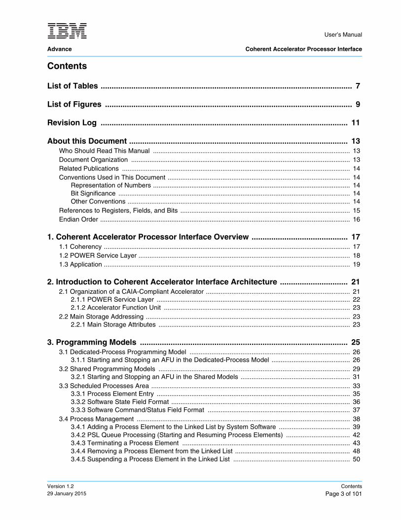
Contents
List of Tables ................................................................................................................... 7
List of Figures ................................................................................................................. 9
Revision Log ................................................................................................................. 11
About this Document .................................................................................................... 13Who Should Read This Manual ............................................................................................................ 13Document Organization ........................................................................................................................ 13Related Publications ............................................................................................................................. 14Conventions Used in This Document .................................................................................................... 14
Representation of Numbers ............................................................................................................ 14Bit Significance ............................................................................................................................... 14Other Conventions .......................................................................................................................... 14
References to Registers, Fields, and Bits ............................................................................................. 15Endian Order ......................................................................................................................................... 16
1. Coherent Accelerator Processor Interface Overview ............................................ 171.1 Coherency ....................................................................................................................................... 171.2 POWER Service Layer .................................................................................................................... 181.3 Application ....................................................................................................................................... 19
2. Introduction to Coherent Accelerator Interface Architecture ............................... 212.1 Organization of a CAIA-Compliant Accelerator ............................................................................... 21
2.1.1 POWER Service Layer .......................................................................................................... 222.1.2 Accelerator Function Unit ...................................................................................................... 23
2.2 Main Storage Addressing ................................................................................................................ 232.2.1 Main Storage Attributes ......................................................................................................... 23
3. Programming Models ............................................................................................... 253.1 Dedicated-Process Programming Model ........................................................................................ 26
3.1.1 Starting and Stopping an AFU in the Dedicated-Process Model ........................................... 263.2 Shared Programming Models ......................................................................................................... 29
3.2.1 Starting and Stopping an AFU in the Shared Models ............................................................ 313.3 Scheduled Processes Area ............................................................................................................. 33
3.3.1 Process Element Entry .......................................................................................................... 353.3.2 Software State Field Format .................................................................................................. 363.3.3 Software Command/Status Field Format .............................................................................. 37
3.4 Process Management ..................................................................................................................... 383.4.1 Adding a Process Element to the Linked List by System Software ....................................... 393.4.2 PSL Queue Processing (Starting and Resuming Process Elements) ................................... 423.4.3 Terminating a Process Element ............................................................................................ 433.4.4 Removing a Process Element from the Linked List ............................................................... 483.4.5 Suspending a Process Element in the Linked List ................................................................ 50
User’s Manual Coherent Accelerator Processor Interface Advance
Contents
Page 4 of 101Version 1.2
29 January 2015
3.4.6 Resume a Process Element .................................................................................................. 543.4.7 Updating a Process Element in the Linked List ..................................................................... 56
4. AFU Descriptor Overview ......................................................................................... 594.1 AFU Descriptor Format ................................................................................................................... 59
5. PSL Accelerator Interface ......................................................................................... 635.1 Accelerator Command Interface ...................................................................................................... 63
5.1.1 Command Ordering ............................................................................................................... 665.1.2 Reservation ............................................................................................................................ 685.1.3 Locks ...................................................................................................................................... 685.1.4 Request for Interrupt Service ................................................................................................. 695.1.5 Parity Handling for the Command Interface ........................................................................... 69
5.2 Accelerator Buffer Interface ............................................................................................................. 695.3 PSL Response Interface ................................................................................................................. 70
5.3.1 Command/Response Flow ..................................................................................................... 725.4 Accelerator MMIO Interface ............................................................................................................ 735.5 Accelerator Control Interface ........................................................................................................... 73
5.5.1 Accelerator Control Interface in the Non-Shared Mode ......................................................... 755.5.2 Accelerator Control Interface for Timebase ........................................................................... 77
6. CAPI Low-Level Management (libcxl) ...................................................................... 796.1 Overview ......................................................................................................................................... 796.2 CAPI Low-Level Management API .................................................................................................. 80
6.2.1 Adapter Information and Availability ...................................................................................... 806.2.2 Accelerated Function Unit Selection ...................................................................................... 816.2.3 Accelerated Function Unit Management ................................................................................ 82
7. AFU Development and Design ................................................................................. 877.1 High-Level Planning ........................................................................................................................ 877.2 Development ................................................................................................................................... 87
7.2.1 Design Language ................................................................................................................... 877.2.2 High-Level Design of the AFU ............................................................................................... 877.2.3 Application Development ....................................................................................................... 887.2.4 AFU Development .................................................................................................................. 887.2.5 Develop Lab Test Plan for the AFU ....................................................................................... 887.2.6 System Simulation of Application and AFU ........................................................................... 887.2.7 Test ........................................................................................................................................ 88
7.3 Best Practices for AFU Design ........................................................................................................ 897.3.1 FPGA Considerations ............................................................................................................ 897.3.2 General PSL Information ....................................................................................................... 897.3.3 Buffer Interface ...................................................................................................................... 897.3.4 PSL Interface Timing ............................................................................................................. 897.3.5 Designing for Performance .................................................................................................... 897.3.6 Simulation .............................................................................................................................. 907.3.7 Debug Considerations ........................................................................................................... 907.3.8 Operating System Error Handling .......................................................................................... 90
User’s Manual
Advance Coherent Accelerator Processor Interface
Version 1.229 January 2015
Contents
Page 5 of 101
8. CAPI Developer Kit Card .......................................................................................... 938.1 Supported CAIA Features ............................................................................................................... 938.2 CAPI Developer Kit Card Hardware ................................................................................................ 938.3 FPGA Build Restrictions .................................................................................................................. 938.4 CAPI Developer Kit Card FPGA Build Flow .................................................................................... 94
8.4.1 Structure of Quartus Project files ........................................................................................... 948.4.2 Build the FPGA ...................................................................................................................... 948.4.3 Load FPGA .rbf File onto the CAPI Developer Kit Card ...................................................... 958.4.4 Timing Closure Hints ............................................................................................................. 958.4.5 Debug Information ................................................................................................................. 95
Glossary ......................................................................................................................... 97

User’s Manual Coherent Accelerator Processor Interface Advance
Contents
Page 6 of 101Version 1.2
29 January 2015
User’s Manual
Advance Coherent Accelerator Processor Interface
Version 1.229 January 2015
List of Tables
Page 7 of 101
List of TablesTable 1. Register References .............................................................................................................. 15
Table 2-1. Sizes of Main Storage Address Spaces ................................................................................. 24
Table 3-1. Scheduled Processes Area Structure .................................................................................... 33
Table 3-2. Process Element Entry Format .............................................................................................. 35
Table 4-1. AFU Descriptor ....................................................................................................................... 60
Table 5-1. Accelerator Command Interface ............................................................................................ 63
Table 5-2. PSL Command Opcodes Directed at the PSL Cache ............................................................ 64
Table 5-3. PSL Command Opcodes That Do Not Allocate in the PSL Cache ........................................ 65
Table 5-4. PSL Command Opcodes for Management ............................................................................ 65
Table 5-5. aXh_cabt Translation Ordering Behavior ............................................................................... 66
Table 5-6. Accelerator Buffer Interface ................................................................................................... 69
Table 5-7. PSL Response Interface ........................................................................................................ 70
Table 5-8. PSL Response Codes ............................................................................................................ 71
Table 5-9. Accelerator MMIO Interface ................................................................................................... 73
Table 5-10. Accelerator Control Interface ................................................................................................. 74
Table 5-11. PSL Control Commands on haX_jcom .................................................................................. 74
Table 7-1. FPGA Resources Available for AFU ...................................................................................... 88

User’s Manual Coherent Accelerator Processor Interface Advance
List of Tables
Page 8 of 101Version 1.2
29 January 2015
User’s Manual
Advance Coherent Accelerator Processor Interface
Version 1.229 January 2015
List of Figures
Page 9 of 101
List of FiguresFigure 1-1. Coherent Accelerator Process Interface Overview ................................................................ 17
Figure 1-2. POWER Service Layer ........................................................................................................... 18
Figure 1-3. CAPI Application on the FPGA .............................................................................................. 19
Figure 2-1. CAIA-Compliant Processor System ....................................................................................... 22
Figure 3-1. Accelerator Invocation Process in the Dedicated Process Model .......................................... 28
Figure 3-2. Accelerator Invocation Process in the Shared Model ............................................................ 32
Figure 3-3. Structure for Scheduled Processes ........................................................................................ 33
Figure 5-1. PSL Command/Response Flow ............................................................................................. 72
Figure 5-2. PSL Accelerator Control Interface Flow in Non-Shared Mode ............................................... 76
User’s Manual Coherent Accelerator Processor Interface Advance
List of Figures
Page 10 of 101Version 1.2
29 January 2015
User’s Manual
Advance Coherent Accelerator Processor Interface
Version 1.229 January 2015
Revision Log
Page 11 of 101
Revision Log
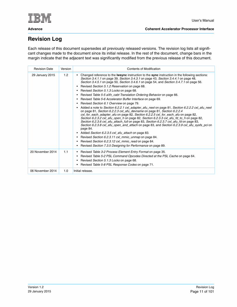
Each release of this document supersedes all previously released versions. The revision log lists all signifi-cant changes made to the document since its initial release. In the rest of the document, change bars in the margin indicate that the adjacent text was significantly modified from the previous release of this document.
Revision Date Version Contents of Modification
29 January 2015 1.2 • Changed reference to the lwsync instruction to the sync instruction in the following sections: Section 3.4.1.1 on page 39, Section 3.4.3.1 on page 43, Section 3.4.4.1 on page 48, Section 3.4.5.1 on page 50, Section 3.4.6.1 on page 54, and Section 3.4.7.1 on page 56.
• Revised Section 5.1.2 Reservation on page 68.• Revised Section 5.1.3 Locks on page 68.• Revised Table 5-5 aXh_cabt Translation Ordering Behavior on page 66.• Revised Table 5-6 Accelerator Buffer Interface on page 69.• Revised Section 6.1 Overview on page 79.• Added a note to Section 6.2.2.1 cxl_adapter_afu_next on page 81, Section 6.2.2.2 cxl_afu_next
on page 81, Section 6.2.2.3 cxl_afu_devname on page 81, Section 6.2.2.4 cxl_for_each_adapter_afu on page 82, Section 6.2.2.5 cxl_for_each_afu on page 82, Section 6.2.3.2 cxl_afu_open_h on page 82, Section 6.2.3.3 cxl_afu_fd_to_h on page 82, Section 6.2.3.6 cxl_afu_attach_full on page 83, Section 6.2.3.7 cxl_afu_fd on page 83, Section 6.2.3.8 cxl_afu_open_and_attach on page 83, and Section 6.2.3.9 cxl_afu_sysfs_pci on page 84.
• Added Section 6.2.3.5 cxl_afu_attach on page 83.• Revised Section 6.2.3.11 cxl_mmio_unmap on page 84.• Revised Section 6.2.3.12 cxl_mmio_read on page 84.• Revised Section 7.3.5 Designing for Performance on page 89.
20 November 2014 1.1 • Revised Table 3-2 Process Element Entry Format on page 35.• Revised Table 5-2 PSL Command Opcodes Directed at the PSL Cache on page 64.• Revised Section 5.1.3 Locks on page 68.• Revised Table 5-8 PSL Response Codes on page 71.
06 November 2014 1.0 Initial release.

User’s Manual Coherent Accelerator Processor Interface Advance
Revision Log
Page 12 of 101Version 1.2
29 January 2015
User’s Manual
Advance Coherent Accelerator Processor Interface
Version 1.229 January 2015
About this Document
Page 13 of 101
About this Document
This user’s guide describes the Coherent Accelerator Processor Interface (CAPI) for the IBM® POWER8 systems. This document is intended to assist users of CAPI implementations in designing applications for hardware acceleration. Maintaining compatibility with the interfaces described in this document, allows appli-cations to migrate from one implementation to another with minor changes.
For a specific implementation of the CAPI, see the documentation for that accelerator.
Who Should Read This Manual
This manual is intended for system software and hardware developers and application programmers who want to develop products that use CAPI. It is assumed that the reader understands operating systems, micro-processor system design, basic principles of reduced instruction set computer (RISC) processing, and details of the Power ISA.
Document Organization
This CAPI User’s Manual contains two types of information. First, it provides a general overview of CAPI, accelerator interfaces, and application library calls to use the accelerator. Second, it provides implementa-tion-specific information about building an accelerator for the supported card, along with the architecture limi-tations of this implementation.
Document Division Description
About this Document Describes this document, related documents, the intended audience, and other general information.
Revision Log Lists all significant changes made to the document since its initial release.
Introduction to Coherent Accelerator Interface Architecture
Provides a high-level overview of the Coherent Accelerator Interface Architecture (CAIA) and the system-software programming models.
PSL Accelerator Interface Describes the interface between the POWER® service layer (PSL) and the accelerator function unit (AFU).
CAPI Low-Level Management (libcxl) Provides an overview, description of the low-level accelerator management, and some programming examples.
AFU Development and Design General information about developing an accelerator functional unit (AFU) and some best practices to consider when designing an AFU.
CAPI Developer Kit Card Describes CAIA implementation details for the CAPI Developer Kit card and the FPGA build flow for the CAPI Developer Kit card.
Glossary Defines terms and acronyms used in this document.
field-programmable gate array
User’s Manual Coherent Accelerator Processor Interface Advance
About this Document
Page 14 of 101Version 1.2
29 January 2015
Related Publications
The following documents can be helpful when reading this specification. Contact your IBM representative to obtain any documents that are not available through OpenPOWER Connect or Power.org.
Conventions Used in This Document
This section explains numbers, bit fields, instructions, and signals that are in this document.
Representation of Numbers
Numbers are generally shown in decimal format, unless designated as follows:
• Hexadecimal values are preceded by an “x” and enclosed in single quotation marks. For example: x‘0A00’.
• Binary values in sentences are shown in single quotation marks.For example: ‘1010’.
Note: A bit value that is immaterial, which is called a “don't care” bit, is represented by an “X.”
Bit Significance
In the documentation, the smallest bit number represents the most significant bit of a field, and the largest bit number represents the least significant bit of a field.
Other Conventions
This document uses the following software documentation conventions:
• Command names or instruction mnemonics are written in bold type. For example: afu_wr and afu_rd.
• Variables are written in italic type. Required parameters are enclosed in angle brackets. Optional param-eters are enclosed in brackets. For example: afu<f,b>_wr[a].
This document uses the following symbols:
Power ISA User Instruction Set Architecture - Book I (Version 2.07)
Power ISA Virtual Environment Architecture - Book II (Version 2.07)
Power ISA Operating Environment Architecture (Server Environment) - Book III-S (Version 2.07)
I/O Design Architecture v2 (IODA2) (Version 2.4+)
Coherent Accelerator Processor Interface (CAPI) Education Package
Coherent Accelerator Processor Interface (CAPI) for POWER8 Systems White Paper
Coherent Accelerator Processor Interface (CAPI) for POWER8 Systems Decision Guide and Development Process
Data Engine for NoSQL - IBM Power Systems™ Edition White Paper
POWER8 Functional Simulator User’s Guide
https://www.power.org/documentation/power-isa-version-2-07/
User’s Manual
Advance Coherent Accelerator Processor Interface
Version 1.229 January 2015
About this Document
Page 15 of 101
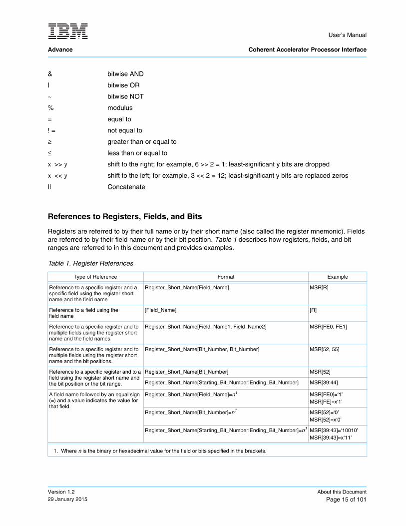
References to Registers, Fields, and Bits
Registers are referred to by their full name or by their short name (also called the register mnemonic). Fields are referred to by their field name or by their bit position. Table 1 describes how registers, fields, and bit ranges are referred to in this document and provides examples.
& bitwise AND
| bitwise OR
~ bitwise NOT
% modulus
= equal to
! = not equal to
≥ greater than or equal to
≤ less than or equal to
x >> y shift to the right; for example, 6 >> 2 = 1; least-significant y bits are dropped
x << y shift to the left; for example, 3 << 2 = 12; least-significant y bits are replaced zeros
|| Concatenate
Table 1. Register References
Type of Reference Format Example
Reference to a specific register and a specific field using the register short name and the field name
Register_Short_Name[Field_Name] MSR[R]
Reference to a field using the field name
[Field_Name] [R]
Reference to a specific register and to multiple fields using the register short name and the field names
Register_Short_Name[Field_Name1, Field_Name2] MSR[FE0, FE1]
Reference to a specific register and to multiple fields using the register short name and the bit positions.
Register_Short_Name[Bit_Number, Bit_Number] MSR[52, 55]
Reference to a specific register and to a field using the register short name and the bit position or the bit range.
Register_Short_Name[Bit_Number] MSR[52]
Register_Short_Name[Starting_Bit_Number:Ending_Bit_Number] MSR[39:44]
A field name followed by an equal sign (=) and a value indicates the value for that field.
Register_Short_Name[Field_Name]=n1 MSR[FE0]=‘1’MSR[FE]=x‘1’
Register_Short_Name[Bit_Number]=n1 MSR[52]=‘0’MSR[52]=x‘0’
Register_Short_Name[Starting_Bit_Number:Ending_Bit_Number]=n1 MSR[39:43]=‘10010’MSR[39:43]=x‘11’
1. Where n is the binary or hexadecimal value for the field or bits specified in the brackets.
User’s Manual Coherent Accelerator Processor Interface Advance
About this Document
Page 16 of 101Version 1.2
29 January 2015
Endian Order
The Power ISA supports both big-endian and little-endian byte-ordering modes. Book I of the Power ISA describes these modes.
The CAIA supports only big-endian byte ordering. Because the CAIA supports only big-endian byte ordering, the POWER service layer (PSL) does not implement the optional little-endian byte-ordering mode of the Power ISA. The data transfers themselves are simply byte moves, without regard to the numerical signifi-cance of any byte. Thus, the big-endian or little-endian issue becomes irrelevant to the actual movement of a block of data. The byte-order mapping only becomes significant when data is fetched or interpreted; for example, by an accelerator function.

User’s Manual
Advance Coherent Accelerator Processor Interface
Version 1.229 January 2015
Coherent Accelerator Processor Interface Overview
Page 17 of 101
1. Coherent Accelerator Processor Interface Overview
The Coherent Accelerator Process Interface (CAPI) is a general term for the infrastructure of attaching a coherent accelerator to an IBM POWER® system. The main application is executed on the host processor with computation-heavy functions executing on the accelerator. The accelerator is a full peer to the host processor, with direct communication with the application. The accelerator uses an unmodified effective address with full access to the real address space. It uses the processor’s page tables directly with page faults handled by system software. Figure 1-1 shows an overview of CAPI.
1.1 Coherency
The Coherent Attached Processor Proxy (CAPP) in the multi-core POWER8 processor extends coherency to the attached accelerator. A directory on the CAPP provides coherency responses on behalf of the acceler-ator. Coherency protocol is tunneled over standard PCI Express links between the CAPP unit on the processor and the POWER service layer (PSL) on the accelerator card.
Figure 1-1. Coherent Accelerator Process Interface Overview
FPGA
Accelerator
Proprietary hardware to enable CAPI
Operating system enablement• Ubuntu LE kernel extensions• Libcxl function calls
Customer application and accelerator
App
Memory (coherent)C
AP
PP
CIe
POWER8 Processor Chip
• The application sets up the data and calls the accelerator functional unit (AFU)
• The accelerator functional unit reads and writes coherent data across the PCIe and communicates with the application − POWER Service Layer (PSL) cache holds coherent data for quick AFU access
POWER8Core
(AFU)
IBM Supplied PSL
OS
CAPI Developer Kit Card
little endian
User’s Manual Coherent Accelerator Processor Interface Advance
Coherent Accelerator Processor Interface Overview
Page 18 of 101Version 1.2
29 January 2015
1.2 POWER Service Layer
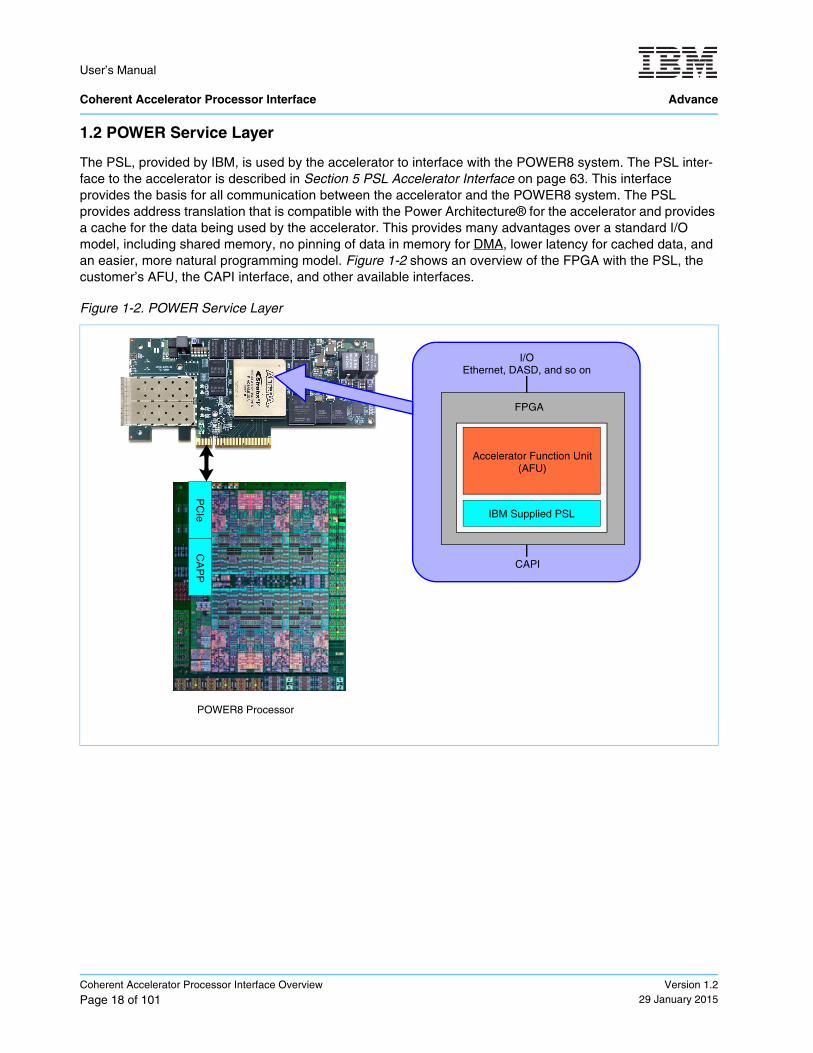
The PSL, provided by IBM, is used by the accelerator to interface with the POWER8 system. The PSL inter-face to the accelerator is described in Section 5 PSL Accelerator Interface on page 63. This interface provides the basis for all communication between the accelerator and the POWER8 system. The PSL provides address translation that is compatible with the Power Architecture® for the accelerator and provides a cache for the data being used by the accelerator. This provides many advantages over a standard I/O model, including shared memory, no pinning of data in memory for DMA, lower latency for cached data, and an easier, more natural programming model. Figure 1-2 shows an overview of the FPGA with the PSL, the customer’s AFU, the CAPI interface, and other available interfaces.
Figure 1-2. POWER Service Layer
PC
IeC
AP
P
IBM Supplied PSL
Accelerator Function Unit(AFU)
FPGA
I/OEthernet, DASD, and so on
CAPI
POWER8 Processor
direct memory access
User’s Manual
Advance Coherent Accelerator Processor Interface
Version 1.229 January 2015
Coherent Accelerator Processor Interface Overview
Page 19 of 101
1.3 Application
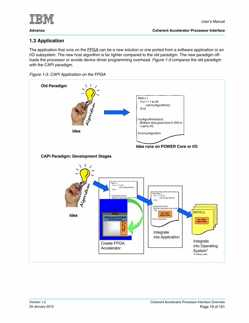
The application that runs on the FPGA can be a new solution or one ported from a software application or an I/O subsystem. The new host algorithm is far lighter compared to the old paradigm. The new paradigm off-loads the processor or avoids device driver programming overhead. Figure 1-3 compares the old paradigm with the CAPI paradigm.
Figure 1-3. CAPI Application on the FPGA
Main ( )For i = 1 to All
call myAlgorithm(i)End
myAlgorithm(input)/Brilliant idea goes here in SW or/ call to I/O
End myAlgorithm
Old Paradigm
Idea
Idea runs on POWER Core or I/O
CAPI Paradigm: Development Stages
Idea
Main ( )For i = 1 to All
call myAlgorithm(i)End
myAlgorithm(input)/Brilliant idea goes here in SW
End myAlgorithm
Create FPGAAccelerator
FPGA
My CAPI
Algorithm
CAPI
IBM Supplied POWER Service Layer
MainNew ( )For i = 1 to All
call myAlgorithm(i)End
myAlgorithm(input)/Brilliant idea goes here in SW/ OR
End myAlgorithm
Integrate into Application
My CAPIAlgorithm
Integrate into OperatingSystem**If widely used
libCXL()
My CAPIAlgorithm
field-programmable gate array
User’s Manual Coherent Accelerator Processor Interface Advance
Coherent Accelerator Processor Interface Overview
Page 20 of 101Version 1.2
29 January 2015
The accelerator algorithm that resides on the FPGA is referred to as the accelerator functional unit (AFU). The AFU is created in a source language that can be synthesized by the FPGA tools. This source language must also be able to be compiled into a simulation environment of the user’s choice. The host algorithm uses the off-loaded AFU through the library calls to an included library, libcxl. For more information about the AFU development cycle, see Section 7 AFU Development and Design on page 87.
Section 2 Introduction to Coherent Accelerator Interface Architecture on page 21 and Section 3 Programming Models on page 25 provide an overview of the architecture for coherent acceleration in a POWER8 system. These sections are provided as background to the programming models provided by the Coherent Acceler-ator Interface Architecture (CAIA). The facilities referenced are not fully described in these sections and are generally not required for an application developer.
Section 4 AFU Descriptor Overview on page 59 provides an overview of the AFU descriptor. The AFU descriptor is a set of registers within the problem state area that contains information about the capabilities of the AFU required by system software.
Section 5 PSL Accelerator Interface on page 63 describes the interface facilities provided by the POWER service layer (PSL) for the AFU. The interface facilities provide the AFU with the ability to read and write main storage, maintain coherency with the system caches, and perform synchronization primitives. Collectively, these facilities are called the accelerator unit interface (AUI).
Section 6 CAPI Low-Level Management (libcxl) on page 79 describes the low-level library interface (libcxl) for CAPI. The libcxl provides an application programming interface (API) for the allocation/de-allocation and communication with a CAPI accelerator.
Section 7 AFU Development and Design on page 87 provides some general information about developing an AFU and some best practices to consider when designing an AFU.
Section 8 CAPI Developer Kit Card on page 93 describes CAIA implementation details for the CAPI Devel-oper Kit card and the FPGA build flow for the CAPI Developer Kit card.
User’s Manual
Advance Coherent Accelerator Processor Interface
Version 1.229 January 2015
Introduction to Coherent Accelerator Interface Architecture
Page 21 of 101
2. Introduction to Coherent Accelerator Interface Architecture
The Coherent Accelerator Interface Architecture (CAIA) defines an accelerator interface structure for coher-ently attaching accelerators to the Power Systems using a standard PCIe bus. The intent is to allow imple-mentation of a wide range of accelerators to optimally address many different market segments.
2.1 Organization of a CAIA-Compliant Accelerator
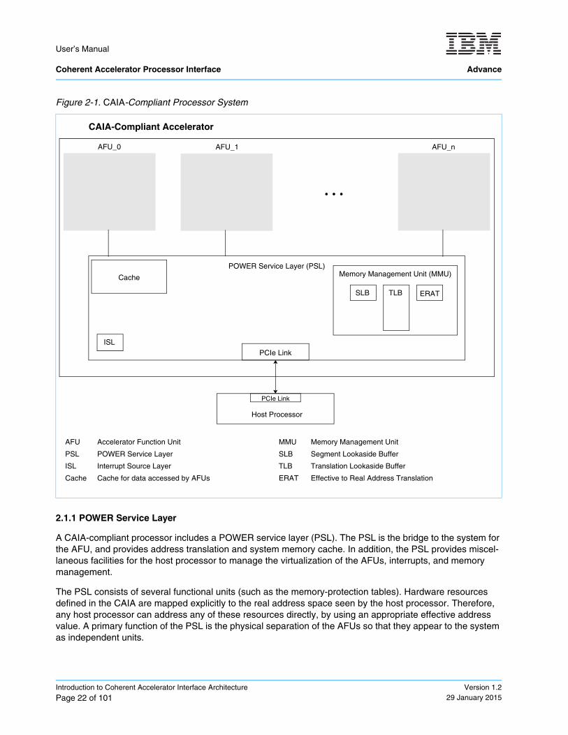
Logically, the CAIA defines two functional components: the PSL and the AFU. The PSL in a CAIA-compliant accelerator provides the interface to the host processor. Effective addresses from an AFU are translated to a physical address in system memory by the PSL. The PSL also provides miscellaneous management for the AFUs. Although the CAIA architecture defines interfaces for up to four AFUs per PSL, early implementations support only a single AFU. The AFU can be dedicated to a single application or shared between multiple applications. However, only the dedicated programming model is currently supported.
Physically, a CAIA-compliant accelerator can consist of a single chip, a multi-chip module (or modules), or multiple single-chip modules on a system board or other second-level package. The design depends on the technology used, and on the cost and performance characteristics of the intended design point.
Figure 2-1 on page 22 illustrates a CAIA-compliant accelerator with several (n) AFUs connected to the PSL. All the AFUs share a single cache.
Peripheral Component Interconnect Express
User’s Manual Coherent Accelerator Processor Interface Advance
Introduction to Coherent Accelerator Interface Architecture
Page 22 of 101Version 1.2
29 January 2015
2.1.1 POWER Service Layer
A CAIA-compliant processor includes a POWER service layer (PSL). The PSL is the bridge to the system for the AFU, and provides address translation and system memory cache. In addition, the PSL provides miscel-laneous facilities for the host processor to manage the virtualization of the AFUs, interrupts, and memory management.
The PSL consists of several functional units (such as the memory-protection tables). Hardware resources defined in the CAIA are mapped explicitly to the real address space seen by the host processor. Therefore, any host processor can address any of these resources directly, by using an appropriate effective address value. A primary function of the PSL is the physical separation of the AFUs so that they appear to the system as independent units.
Figure 2-1. CAIA-Compliant Processor System
POWER Service Layer (PSL)
AFU_0 AFU_1 AFU_n
AFU Accelerator Function Unit MMU Memory Management Unit
PSL POWER Service Layer SLB Segment Lookaside Buffer
ISL Interrupt Source Layer TLB Translation Lookaside Buffer
Cache Cache for data accessed by AFUs ERAT Effective to Real Address Translation
Host Processor
CAIA-Compliant Accelerator
Memory Management Unit (MMU)
SLB TLB
ISL
ERAT
PCIe Link
PCIe Link
Cache
User’s Manual
Advance Coherent Accelerator Processor Interface
Version 1.229 January 2015
Introduction to Coherent Accelerator Interface Architecture
Page 23 of 101
2.1.2 Accelerator Function Unit
Note: The AFU functional definition is outside the scope of the CAPI User’s Manual. The AFU functional def-inition is owned by the CAPI solution provider.
A CAIA-compliant processor includes one or more AFUs. The AFUs are user-defined functions for acceler-ating applications. They typically process data and initiate any required data transfers to perform their allo-cated tasks.
The purpose of an AFU is to provide applications with a higher computational unit density for hardware accel-eration of functions to improve the performance of the application and off-load the host processor. Using an AFU for application acceleration allows for cost-effective processing over a wide range of applications.
When an application requests use of an AFU, a process element is added to the process-element linked list that describes the application’s process state. The process element also contains a work element descriptor (WED) provided by the application. The WED can contain the full description of the job to be performed or a pointer to other main memory structures in the application’s memory space. Several programming models are described providing for an AFU to be used by any application or for an AFU to be dedicated to a single appli-cation. See Section 3 Programming Models on page 25 for details.
2.2 Main Storage Addressing
The addressing of main storage in the CAIA is compatible with the addressing defined in the Power ISA. The CAIA builds upon the concepts of the Power ISA and extends the addressing of main storage to the AFU.
The AFU uses an effective address to access main storage. The effective address is computed by the AFU and is provided to the PSL. The effective address is translated to a real address according to the procedures described in the overview of address translation in Power ISA, Book III. The real address is the location in main storage that is referenced by the translated effective address.
All the AFUs share main storage with the host processors. This storage area can either be uniform in struc-ture or can be part of a hierarchical cache structure. Programs reference this level of storage by using an effective address.
2.2.1 Main Storage Attributes
The main storage of a system typically includes both general-purpose and nonvolatile storage. It also includes special-purpose hardware registers or arrays used for functions such as system configuration, data-transfer synchronization, memory-mapped I/O, and I/O subsystems.
User’s Manual Coherent Accelerator Processor Interface Advance
Introduction to Coherent Accelerator Interface Architecture
Page 24 of 101Version 1.2
29 January 2015
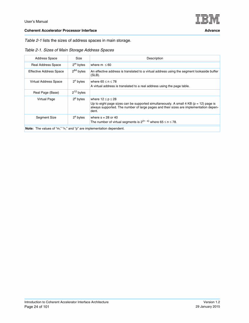
Table 2-1 lists the sizes of address spaces in main storage.
Table 2-1. Sizes of Main Storage Address Spaces
Address Space Size Description
Real Address Space 2m bytes where m ≤ 60
Effective Address Space 264 bytes An effective address is translated to a virtual address using the segment lookaside buffer (SLB).
Virtual Address Space 2n bytes where 65 ≤ n ≤ 78A virtual address is translated to a real address using the page table.
Real Page (Base) 212 bytes
Virtual Page 2p bytes where 12 ≤ p ≤ 28 Up to eight page sizes can be supported simultaneously. A small 4 KB (p = 12) page is always supported. The number of large pages and their sizes are implementation depen-dent.
Segment Size 2s bytes where s = 28 or 40The number of virtual segments is 2(n - s) where 65 ≤ n ≤ 78.
Note: The values of “m,” “n,” and “p” are implementation dependent.
User’s Manual
Advance Coherent Accelerator Processor Interface
Version 1.229 January 2015
Programming Models
Page 25 of 101
3. Programming Models
The Coherent Accelerator Interface Architecture (CAIA) defines several programming models for virtualiza-tion of an acceleration function unit (AFU):
• Dedicated-process programming model (no AFU virtualization)
• Shared programming models, which include these two types:
– PSL-controlled shared programming models (AFU time-sliced virtualization)– AFU-directed shared programming models (AFU-controlled process element selection virtualization)
Note: The shared programming models are for future releases only. Currently, libcxl only supports the dedi-cated-programming model. Additional programming models might be added in the future.
In the dedicated process model, the AFU is dedicated to a single application or process under a single oper-ating system. The single application can act as an “Application as a Service” and funnel other application requests to the accelerator, providing virtualization within a partition.
In the PSL-controlled shared and AFU-directed shared programming models, the AFU can be shared by multiple partitions. The shared models require a system hypervisor to virtualize the AFU so that each oper-ating system can access the AFU. For single-partition systems not running a hypervisor, the AFU is owned by the operating system. In both cases, the operating system can virtualize the AFU so that each process or application can access the AFU.
For the AFU-directed shared programming model, the AFU selects a process element using a process handle. The process handle is an implementation-specific value provided to the host process when regis-tering its context with the AFU (that is, calling system software to add the process element to the process element linked list). While the process handle is implementation specific, the lower 16-bits of the process handle must be the offset of the process element within the process element linked list.
The “process element” contains the process state for the corresponding application. The work element descriptor (WED) contained in the process element can be a single job requested by an application or contains a pointer to a queue of jobs. In the latter case, the WED is a pointer to the job request queue in the application’s address space.
This document does not cover all aspects of the programming models. The intent of this section is to provide a reference for how the AFUs can be shared by all or a subset of the processes in the system. This section defines the infrastructure for setting up the process state and sending a work element descriptor (WED) to an AFU to start a job in a virtualized environment. The function performed by an AFU is implementation depen-dent.
Architecture Note: The AFU-directed programming model, where the AFU selects a context from the process element linked list to use for a transfer, is intended for the Networking and Storage market segments. For these types of applications, the required address context is selected based on a packet received from a net-work or which process is accessing storage. A CAIA-compliant device can also act as system memory or the lowest point of coherency (LPC). In this model, the process element and address translation are not required. The LPC model can also be used in combination with the other programming models but might not be supported by all devices.
User’s Manual Coherent Accelerator Processor Interface Advance
Programming Models
Page 26 of 101Version 1.2
29 January 2015
3.1 Dedicated-Process Programming Model
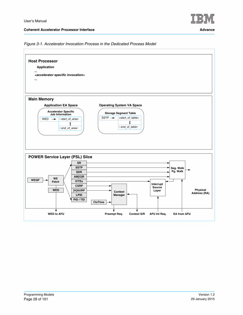
The dedicated-process programming model is implementation specific. Figure 3-1 Accelerator Invocation Process in the Dedicated Process Model on page 28 shows how an application invokes an accelerator under the dedicated-process programming model.
In this model, a single process owns the AFU. Because the AFU is dedicated to a single process, the programming model is not defined in this document. For more information, see the documentation for the specific implementation.
Because the AFU is owned by a single process, the hypervisor initializes the PSL for the owning partition and the operating system initializes the PSL for the owning process at the time when the AFU is assigned. The following information is initialized:
Note: The PSL architecture allows multiple AFUs (available in future implementations). These registers are duplicated for each AFU. Each of these duplicated registers is called a slice.
Registers initialized by the hypervisor:
• PSL Slice Control Register (PSL_SCNTL_An)• Real Address (RA) Scheduled Processes Area Pointer (PSL_SPAP_An) {disable}• PSL Authority Mask Override Register (PSL_AMOR_An)• Interrupt Vector Table Entry Offset (PSL_IVTE_Offset_An)• Interrupt Vector Table Entry Limit (PSL_IVTE_Limit_An)• PSL State Register (PSL_SR_An)• PSL Logical Partition ID (PSL_LPID_An)• Real address (RA) Hypervisor Accelerator Utilization Record Pointer (HAURP_An) {disable}• PSL Storage Description Register (PSL_SDR_An)
Registers initialized by the operating system:
• PSL Process and Thread Identification (PSL_PID_TID_An)• Effective Address (EA) Context Save/Restore Pointer (CSRP_An) {disable}• Virtual Address (VA) Accelerator Utilization Record Pointer (AURP0_An) and (AURP1_An) {disable}• Virtual Address (VA) Storage Segment Table Pointer (SSTP0_An) and (SSTP1_An)• PSL Authority Mask (PSL_AMR_An)• PSL Work Element Descriptor (PSL_WED_An)
3.1.1 Starting and Stopping an AFU in the Dedicated-Process Model
In a dedicated-process programming model, an AFU is started and stopped by system software (operating system or hypervisor). This section describes the sequence used by system software to start an AFU and is provided for reference only. An application simply calls libcxl with the desired WED, and libcxl performs the system software calls described in the following procedures. The WED is specific to each AFU. It contains all the information an AFU requires to do its work or it can be a pointer to a memory location where the applica-tion has set up a command queue of work to be completed. See Section 6 CAPI Low-Level Management (libcxl) on page 79 for additional information.
Use the following procedure to start an AFU.
1. System software must initialize the state of the PSL.All the required Privileged 1, Privileged 1 Slice, and Privileged 2 Slice registers must be initialized so that the address context for the processes and other contexts such as the interrupt vector table entries can be used.
User’s Manual
Advance Coherent Accelerator Processor Interface
Version 1.229 January 2015
Programming Models
Page 27 of 101
2. System software must set the AFU Slice Reset bit in the AFU_Cntl_An Register (AFU_Cntl_An[RA]).Setting the AFU Slice Reset starts a reset sequence for the corresponding AFU. Initiating a reset sequence also disables the AFU. The AFU does not respond to the problem state MMIO region while dis-abled.
3. System software must poll the AFU Slice Reset Status for the AFU Slice Reset Sequence to be complete (AFU_Cntl_An[RS]=‘10’).
4. System software must set the WED if required by the AFU at start time.The WED is initialized by writing a 64-bit WED value to the PSL_WED_An Register. System software writes the WED that was passed to libcxl by the application.
5. System software must set the AFU Enable bit in the AFU_Cntl_An Register (AFU_Cntl_An[E]).The state of the AFU Enable Status must be a ‘00’ before system software setting can set the AFU Enable bit to a ‘1’ for a start command to be issued to the AFU by the PSL. The WED is passed to the AFU when the start command is issued.
6. System software must poll the AFU Enable Status for the AFU Slice Enabled (AFU_Cntl_An[ES]=‘10’).The AFU_Cntl_An[ES] field is set to ‘10’ when the PSL and AFU are initialized, running, and able to accept MMIO. After the AFU is running, system memory accesses can be performed by the AFU and problem state MMIOs can be performed by software.
Note: If problem state registers are required to be initialized in the AFU before the application starts, the AFU must provide a mechanism for starting the accelerator and must not depend on the start command issued by the PSL.
Use the following procedure to stop an AFU.
1. System software must set the AFU Slice Reset bit in the AFU_Cntl_An Register (AFU_Cntl_An[RA]).Setting the AFU Slice Reset starts a reset sequence for the corresponding AFU. Initiating a reset sequence also disables the AFU. The AFU does not respond to the Problem State MMIO region while disabled.
2. System software must poll the AFU Slice Reset Status for the AFU Slice Reset Sequence to be complete (AFU_Cntl_An[RS] = ‘10’).
memory mapped input/output
User’s Manual Coherent Accelerator Processor Interface Advance
Programming Models
Page 28 of 101Version 1.2
29 January 2015
Figure 3-1. Accelerator Invocation Process in the Dedicated Process Model
Application
POWER Service Layer (PSL) Slice
WEFetch
WED to AFU
Seg. WalkPg. Walk
EA from AFU
Physical Address (RA)
AFU Int Req.
ContextManager
Preempt Req. Context S/R
WEQP
WED
SR
SSTP
SDR
AM[O]R
IVTEs
CSRP
[H]AURP
LPID
PID / TIDCtxTime
Host Processor
Main Memory
...<accelerator specific invocation>...
Operating System VA Space
Storage Segment Table
SSTP <start_of_table>
<end_of_table>
Application EA Space
Accelerator SpecificJob Information
WED <start_of_area>
<end_of_area>
InterruptSourceLayer
User’s Manual
Advance Coherent Accelerator Processor Interface
Version 1.229 January 2015
Programming Models
Page 29 of 101
3.2 Shared Programming Models
Note: This section is for future releases only. Currently, libcxl only supports the dedicated programming model.
The shared programming models allow for all or a subset of processes from all or a subset of partitions in the system to use an AFU. There are two programming models where the AFU is shared by multiple processes and partitions; PSL time-sliced shared and AFU-directed shared.
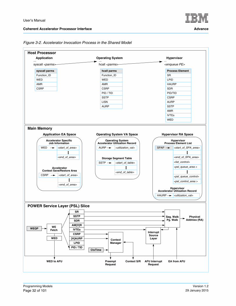
Figure 3-2 on page 32 shows how an application invokes an AFU under the shared programming model.
In this model, the system hypervisor owns the AFU and makes the function available to all operating systems. For an AFU to support virtualization by the system hypervisor, the AFU must adhere to the following require-ments:
• An application’s job request must be autonomous (that is, the state does not need to be maintained between jobs),-- OR --The AFU must provide a context save and restore mechanism.
• An application’s job request must be guaranteed by the AFU to complete in a specified amount of time, including any translation faults, -- OR --The AFU must provide the ability to preempt the processing of the job.
• The AFU must be guaranteed fairness between processes when operating in the AFU-directed shared programming model.
In the case where an AFU can be preempted, the AFU can either require the current job to be restarted from the beginning, or it can provide a method to save and restore the context so that the current job can be restarted from the preemption point at a later time.
For the shared model, the application is required to make an operating-system system call with at least the following information:
• An AFU type (AFU_Type)The AFU type describes the targeted acceleration function for the system call. The AFU_Type is a system-specific value.
• A work element descriptor (WED)This document does not define the contents of the WED. The WED is AFU implementation specific and can be in the form of an AFU command, an effective address pointer to a user-defined structure, an effec-tive address pointer to a queue of commands, or any other data structure to describe the work to be done by the AFU.
• An Authority Mask Register (AMR) valueThe AMR value is the AMR state to use for the current process. The value passed to the operating sys-tem is similar to an application setting the AMR in the processor by using spr 13 or by calling a system library. If the PSL and AFU implementations do not support a User Authority Mask Override Register (UAMOR), the operating system should apply the current UAMOR value to the AMR value before passing the AMR in the hypervisor call (hcall). The UAMOR is not described in this document. For more informa-tion about the UAMOR, see the Power ISA, Book III. The hypervisor can optionally apply the current Authority Mask Override Register (AMOR) value before placing the AMR into the process element. The PSL applies the PSL_AMOR_An when updating the PSL_AMR_An Register from the process element.
special purpose register
User’s Manual Coherent Accelerator Processor Interface Advance
Programming Models
Page 30 of 101Version 1.2
29 January 2015
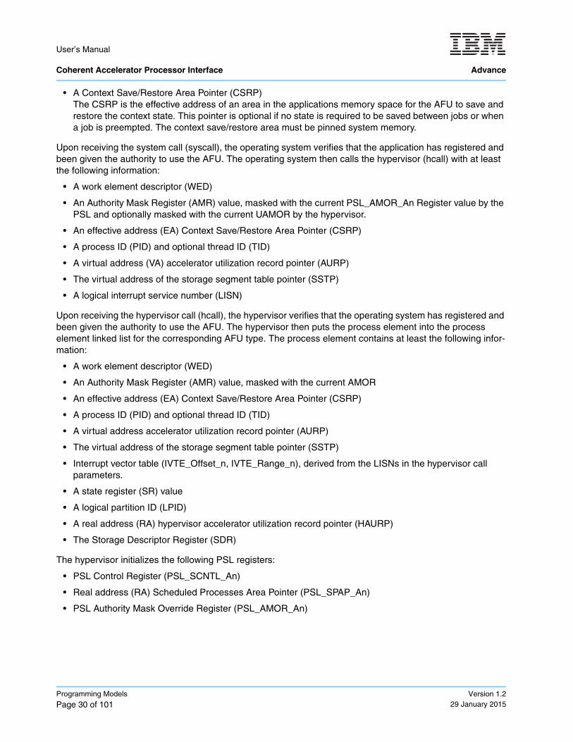
• A Context Save/Restore Area Pointer (CSRP)The CSRP is the effective address of an area in the applications memory space for the AFU to save and restore the context state. This pointer is optional if no state is required to be saved between jobs or when a job is preempted. The context save/restore area must be pinned system memory.
Upon receiving the system call (syscall), the operating system verifies that the application has registered and been given the authority to use the AFU. The operating system then calls the hypervisor (hcall) with at least the following information:
• A work element descriptor (WED)
• An Authority Mask Register (AMR) value, masked with the current PSL_AMOR_An Register value by the PSL and optionally masked with the current UAMOR by the hypervisor.
• An effective address (EA) Context Save/Restore Area Pointer (CSRP)
• A process ID (PID) and optional thread ID (TID)
• A virtual address (VA) accelerator utilization record pointer (AURP)
• The virtual address of the storage segment table pointer (SSTP)
• A logical interrupt service number (LISN)
Upon receiving the hypervisor call (hcall), the hypervisor verifies that the operating system has registered and been given the authority to use the AFU. The hypervisor then puts the process element into the process element linked list for the corresponding AFU type. The process element contains at least the following infor-mation:
• A work element descriptor (WED)
• An Authority Mask Register (AMR) value, masked with the current AMOR
• An effective address (EA) Context Save/Restore Area Pointer (CSRP)
• A process ID (PID) and optional thread ID (TID)
• A virtual address accelerator utilization record pointer (AURP)
• The virtual address of the storage segment table pointer (SSTP)
• Interrupt vector table (IVTE_Offset_n, IVTE_Range_n), derived from the LISNs in the hypervisor call parameters.
• A state register (SR) value
• A logical partition ID (LPID)
• A real address (RA) hypervisor accelerator utilization record pointer (HAURP)
• The Storage Descriptor Register (SDR)
The hypervisor initializes the following PSL registers:
• PSL Control Register (PSL_SCNTL_An)
• Real address (RA) Scheduled Processes Area Pointer (PSL_SPAP_An)
• PSL Authority Mask Override Register (PSL_AMOR_An)
User’s Manual
Advance Coherent Accelerator Processor Interface
Version 1.229 January 2015
Programming Models
Page 31 of 101
3.2.1 Starting and Stopping an AFU in the Shared Models
In the shared, PSL-controlled time-sliced programming model, the AFU is automatically started and stopped by the PSL. The PSL essentially follows the procedures defined in Section 3.1.1 Starting and Stopping an AFU in the Dedicated-Process Model on page 26.
In the AFU-directed shared programming model, starting and stopping an AFU process is an AFU implemen-tation-specific procedure.
User’s Manual Coherent Accelerator Processor Interface Advance
Programming Models
Page 32 of 101Version 1.2
29 January 2015
Figure 3-2. Accelerator Invocation Process in the Shared Model
Application
Host Processor
Main Memory
...syscall <parms>
syscall parms
Function_ID
WED
AMR
CSRP
Operating System...hcall <parms>
hcall parms
Function_ID
WED
AMR
CSRP
PID / TID
SSTP
LISN
AURP
Hypervisor...<enqueue PE>
Process Element
SR
LPID
HAURP
SDR
PID/TID
CSRP
AURP
SSTP
AMR
IVTEs
WED
Application EA Space
Accelerator SpecificJob Information
WED <start_of_area>
<end_of_area>
AcceleratorContext Save/Restore Area
CSRP <start_of_area>
<end_of_area>
Hypervisor RA Space
Hypervisor Process Element List
SPAP <start_of_SPA_area>
<end_of_SPA_area>
<list_control>
<psl_queue_area >
<psl_queue_control>
<psl_control_area >
Hypervisor Accelerator Utilization Record
HAURP <utilization_val>
Operating System VA Space
Operating System Accelerator Utilization Record
AURP <utilization_val>
Storage Segment Table
SSTP <start_of_table>
<end_of_table>
POWER Service Layer (PSL) Slice
WEFetch
WED to AFU
Seg. WalkPg. Walk
EA from AFU
Physical Address (RA)
AFU Interrupt Request
ContextManager
Preempt Request
Context S/R
WEQP
WED
SR
SSTP
SDR
AM[O]R
IVTEs
CSRP
[H]AURP
LPID
PID / TIDCtxTime
InterruptSourceLayer
User’s Manual
Advance Coherent Accelerator Processor Interface
Version 1.229 January 2015
Programming Models
Page 33 of 101
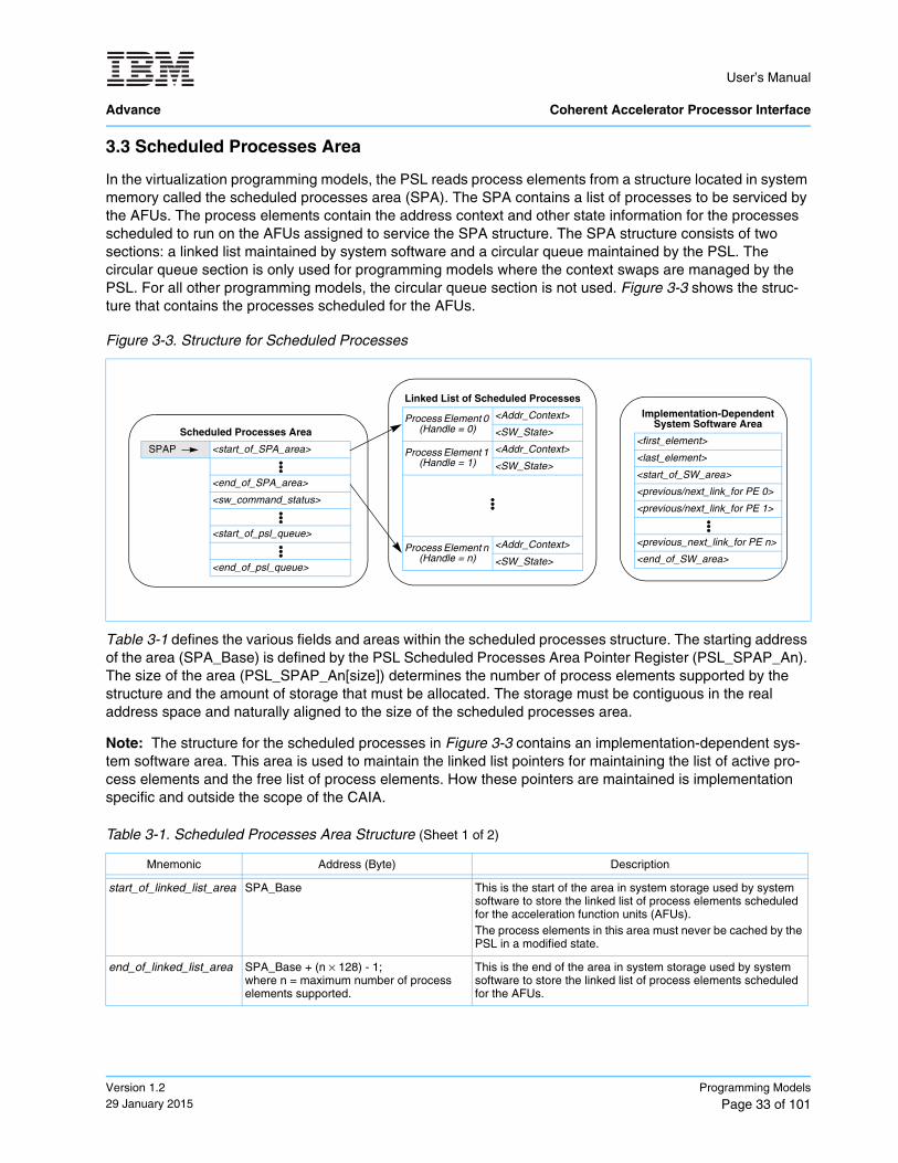
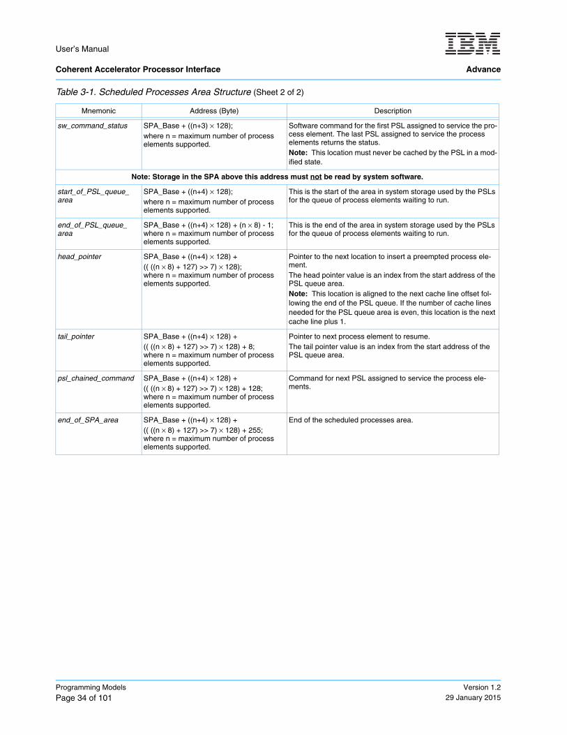
3.3 Scheduled Processes Area
In the virtualization programming models, the PSL reads process elements from a structure located in system memory called the scheduled processes area (SPA). The SPA contains a list of processes to be serviced by the AFUs. The process elements contain the address context and other state information for the processes scheduled to run on the AFUs assigned to service the SPA structure. The SPA structure consists of two sections: a linked list maintained by system software and a circular queue maintained by the PSL. The circular queue section is only used for programming models where the context swaps are managed by the PSL. For all other programming models, the circular queue section is not used. Figure 3-3 shows the struc-ture that contains the processes scheduled for the AFUs.
Table 3-1 defines the various fields and areas within the scheduled processes structure. The starting address of the area (SPA_Base) is defined by the PSL Scheduled Processes Area Pointer Register (PSL_SPAP_An). The size of the area (PSL_SPAP_An[size]) determines the number of process elements supported by the structure and the amount of storage that must be allocated. The storage must be contiguous in the real address space and naturally aligned to the size of the scheduled processes area.
Note: The structure for the scheduled processes in Figure 3-3 contains an implementation-dependent sys-tem software area. This area is used to maintain the linked list pointers for maintaining the list of active pro-cess elements and the free list of process elements. How these pointers are maintained is implementation specific and outside the scope of the CAIA.
Figure 3-3. Structure for Scheduled Processes
Table 3-1. Scheduled Processes Area Structure (Sheet 1 of 2)
Mnemonic Address (Byte) Description
start_of_linked_list_area SPA_Base This is the start of the area in system storage used by system software to store the linked list of process elements scheduled for the acceleration function units (AFUs).The process elements in this area must never be cached by the PSL in a modified state.
end_of_linked_list_area SPA_Base + (n × 128) - 1;where n = maximum number of process elements supported.
This is the end of the area in system storage used by system software to store the linked list of process elements scheduled for the AFUs.
Linked List of Scheduled Processes
Process Element 0 (Handle = 0)
<Addr_Context>
<SW_State>
Process Element 1 (Handle = 1)
<Addr_Context>
<SW_State>
Process Element n (Handle = n)
<Addr_Context>
<SW_State>
Scheduled Processes Area
SPAP <start_of_SPA_area>
<end_of_SPA_area>
<sw_command_status>
<start_of_psl_queue>
<end_of_psl_queue>
Implementation-Dependent System Software Area
<first_element>
<last_element>
<start_of_SW_area>
<previous/next_link_for PE 0>
<previous/next_link_for PE 1>
<previous_next_link_for PE n>
<end_of_SW_area>
User’s Manual Coherent Accelerator Processor Interface Advance
Programming Models
Page 34 of 101Version 1.2
29 January 2015
sw_command_status SPA_Base + ((n+3) × 128);where n = maximum number of process elements supported.
Software command for the first PSL assigned to service the pro-cess element. The last PSL assigned to service the process elements returns the status. Note: This location must never be cached by the PSL in a mod-ified state.
Note: Storage in the SPA above this address must not be read by system software.
start_of_PSL_queue_ area
SPA_Base + ((n+4) × 128);where n = maximum number of process elements supported.
This is the start of the area in system storage used by the PSLs for the queue of process elements waiting to run.
end_of_PSL_queue_ area
SPA_Base + ((n+4) × 128) + (n × 8) - 1;where n = maximum number of process elements supported.
This is the end of the area in system storage used by the PSLs for the queue of process elements waiting to run.
head_pointer SPA_Base + ((n+4) × 128) + (( ((n × 8) + 127) >> 7) × 128);where n = maximum number of process elements supported.
Pointer to the next location to insert a preempted process ele-ment.The head pointer value is an index from the start address of the PSL queue area. Note: This location is aligned to the next cache line offset fol-lowing the end of the PSL queue. If the number of cache lines needed for the PSL queue area is even, this location is the next cache line plus 1.
tail_pointer SPA_Base + ((n+4) × 128) + (( ((n × 8) + 127) >> 7) × 128) + 8;where n = maximum number of process elements supported.
Pointer to next process element to resume.The tail pointer value is an index from the start address of the PSL queue area.
psl_chained_command SPA_Base + ((n+4) × 128) + (( ((n × 8) + 127) >> 7) × 128) + 128;where n = maximum number of process elements supported.
Command for next PSL assigned to service the process ele-ments.
end_of_SPA_area SPA_Base + ((n+4) × 128) + (( ((n × 8) + 127) >> 7) × 128) + 255;where n = maximum number of process elements supported.
End of the scheduled processes area.
Table 3-1. Scheduled Processes Area Structure (Sheet 2 of 2)
Mnemonic Address (Byte) Description
User’s Manual
Advance Coherent Accelerator Processor Interface
Version 1.229 January 2015
Programming Models
Page 35 of 101
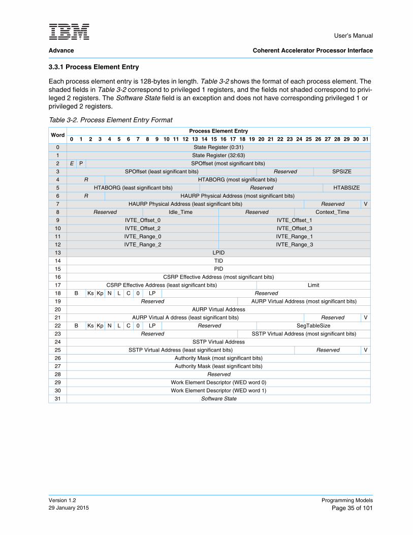
3.3.1 Process Element Entry
Each process element entry is 128-bytes in length. Table 3-2 shows the format of each process element. The shaded fields in Table 3-2 correspond to privileged 1 registers, and the fields not shaded correspond to privi-leged 2 registers. The Software State field is an exception and does not have corresponding privileged 1 or privileged 2 registers.
Table 3-2. Process Element Entry Format
WordProcess Element Entry
0 1 2 3 4 5 6 7 8 9 10 11 12 13 14 15 16 17 18 19 20 21 22 23 24 25 26 27 28 29 30 31
0 State Register (0:31)
1 State Register (32:63)
2 E P SPOffset (most significant bits)
3 SPOffset (least significant bits) Reserved SPSIZE
4 R HTABORG (most significant bits)
5 HTABORG (least significant bits) Reserved HTABSIZE
6 R HAURP Physical Address (most significant bits)
7 HAURP Physical Address (least significant bits) Reserved V
8 Reserved Idle_Time Reserved Context_Time
9 IVTE_Offset_0 IVTE_Offset_1
10 IVTE_Offset_2 IVTE_Offset_3
11 IVTE_Range_0 IVTE_Range_1
12 IVTE_Range_2 IVTE_Range_3
13 LPID
14 TID
15 PID
16 CSRP Effective Address (most significant bits)
17 CSRP Effective Address (least significant bits) Limit
18 B Ks Kp N L C 0 LP Reserved
19 Reserved AURP Virtual Address (most significant bits)
20 AURP Virtual Address
21 AURP Virtual A ddress (least significant bits) Reserved V
22 B Ks Kp N L C 0 LP Reserved SegTableSize
23 Reserved SSTP Virtual Address (most significant bits)
24 SSTP Virtual Address
25 SSTP Virtual Address (least significant bits) Reserved V
26 Authority Mask (most significant bits)
27 Authority Mask (least significant bits)
28 Reserved
29 Work Element Descriptor (WED word 0)
30 Work Element Descriptor (WED word 1)
31 Software State
User’s Manual Coherent Accelerator Processor Interface Advance
Programming Models
Page 36 of 101Version 1.2
29 January 2015
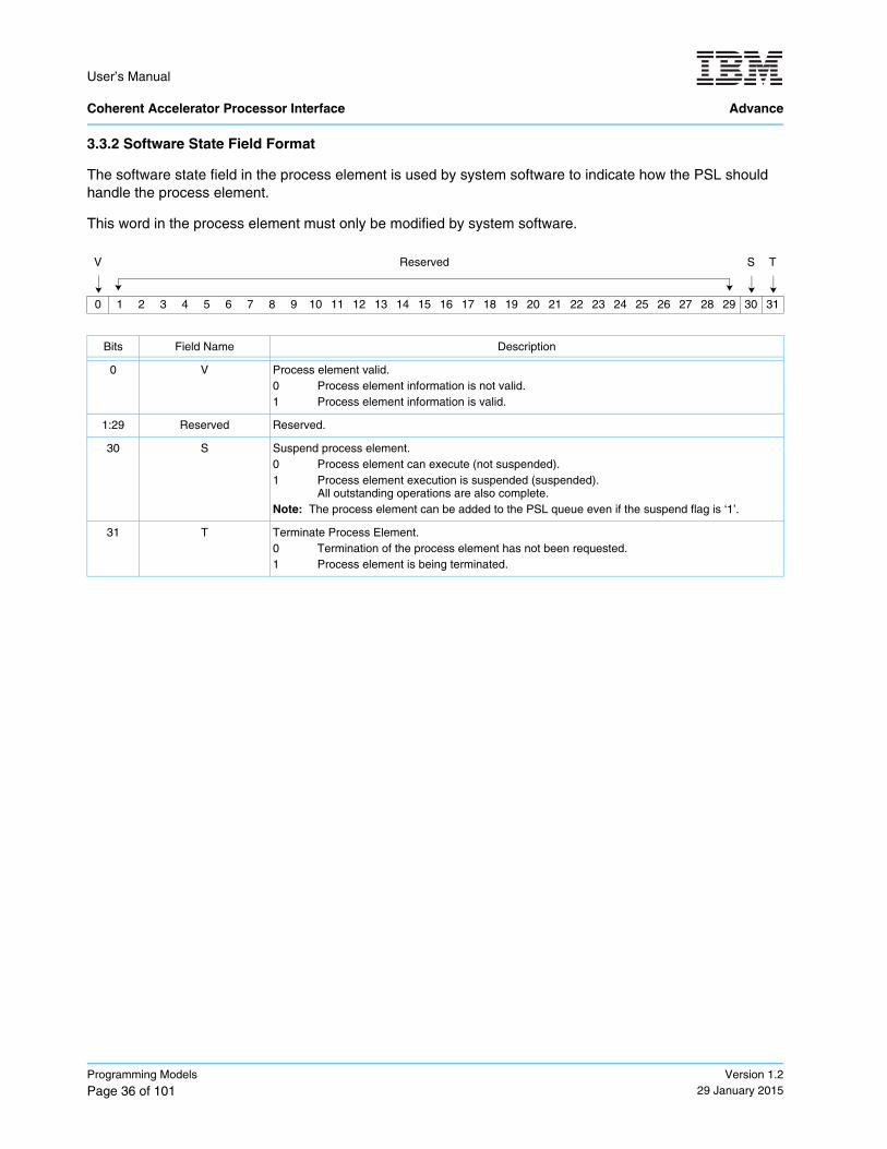
3.3.2 Software State Field Format
The software state field in the process element is used by system software to indicate how the PSL should handle the process element.
This word in the process element must only be modified by system software.
V Reserved S T
0 1 2 3 4 5 6 7 8 9 10 11 12 13 14 15 16 17 18 19 20 21 22 23 24 25 26 27 28 29 30 31
Bits Field Name Description
0 V Process element valid.0 Process element information is not valid.1 Process element information is valid.
1:29 Reserved Reserved.
30 S Suspend process element.0 Process element can execute (not suspended).1 Process element execution is suspended (suspended).
All outstanding operations are also complete.Note: The process element can be added to the PSL queue even if the suspend flag is ‘1’.
31 T Terminate Process Element.0 Termination of the process element has not been requested.1 Process element is being terminated.
User’s Manual
Advance Coherent Accelerator Processor Interface
Version 1.229 January 2015
Programming Models
Page 37 of 101
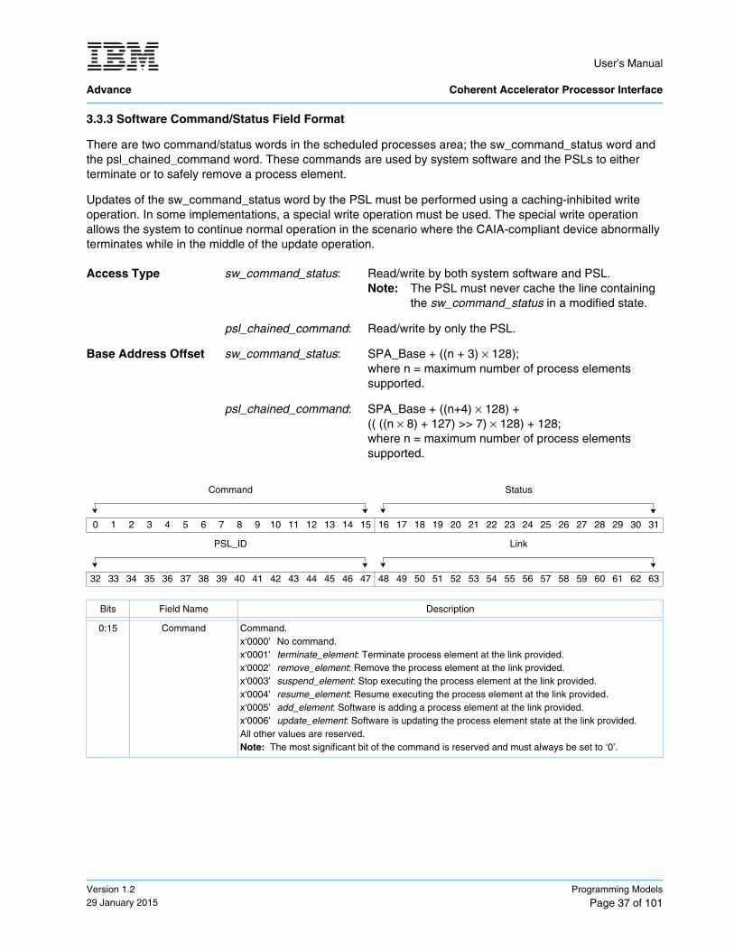
3.3.3 Software Command/Status Field Format
There are two command/status words in the scheduled processes area; the sw_command_status word and the psl_chained_command word. These commands are used by system software and the PSLs to either terminate or to safely remove a process element.
Updates of the sw_command_status word by the PSL must be performed using a caching-inhibited write operation. In some implementations, a special write operation must be used. The special write operation allows the system to continue normal operation in the scenario where the CAIA-compliant device abnormally terminates while in the middle of the update operation.
Access Type sw_command_status: Read/write by both system software and PSL.Note: The PSL must never cache the line containing
the sw_command_status in a modified state.
psl_chained_command: Read/write by only the PSL.
Base Address Offset sw_command_status: SPA_Base + ((n + 3) × 128); where n = maximum number of process elementssupported.
psl_chained_command: SPA_Base + ((n+4) × 128) + (( ((n × 8) + 127) >> 7) × 128) + 128;where n = maximum number of process elementssupported.
Command Status
0 1 2 3 4 5 6 7 8 9 10 11 12 13 14 15 16 17 18 19 20 21 22 23 24 25 26 27 28 29 30 31
PSL_ID Link
32 33 34 35 36 37 38 39 40 41 42 43 44 45 46 47 48 49 50 51 52 53 54 55 56 57 58 59 60 61 62 63
Bits Field Name Description
0:15 Command Command.x‘0000’ No command.x‘0001’ terminate_element: Terminate process element at the link provided.x‘0002’ remove_element: Remove the process element at the link provided. x‘0003’ suspend_element: Stop executing the process element at the link provided.x‘0004’ resume_element: Resume executing the process element at the link provided. x‘0005’ add_element: Software is adding a process element at the link provided. x‘0006’ update_element: Software is updating the process element state at the link provided. All other values are reserved.Note: The most significant bit of the command is reserved and must always be set to ‘0’.
User’s Manual Coherent Accelerator Processor Interface Advance
Programming Models
Page 38 of 101Version 1.2
29 January 2015
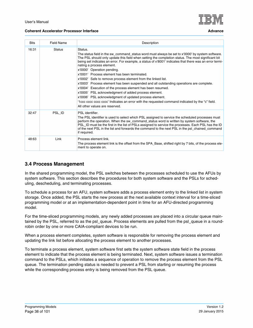
3.4 Process Management
In the shared programming model, the PSL switches between the processes scheduled to use the AFUs by system software. This section describes the procedures for both system software and the PSLs for sched-uling, descheduling, and terminating processes.
To schedule a process for an AFU, system software adds a process element entry to the linked list in system storage. Once added, the PSL starts the new process at the next available context interval for a time-sliced programming model or at an implementation-dependent point in time for an AFU-directed programming model.
For the time-sliced programming models, any newly added processes are placed into a circular queue main-tained by the PSL, referred to as the psl_queue. Process elements are pulled from the psl_queue in a round-robin order by one or more CAIA-compliant devices to be run.
When a process element completes, system software is responsible for removing the process element and updating the link list before allocating the process element to another processes.
To terminate a process element, system software first sets the system software state field in the process element to indicate that the process element is being terminated. Next, system software issues a termination command to the PSLs, which initiates a sequence of operation to remove the process element from the PSL queue. The termination pending status is needed to prevent a PSL from starting or resuming the process while the corresponding process entry is being removed from the PSL queue.
16:31 Status Status.The status field in the sw_command_status word must always be set to x‘0000’ by system software. The PSL should only update this field when setting the completion status. The most significant bit being set indicates an error. For example, a status of x‘8001’ indicates that there was an error termi-nating a process element.x‘0000’ Operation pending.x‘0001’ Process element has been terminated.x‘0002’ Safe to remove process element from the linked list. x‘0003’ Process element has been suspended and all outstanding operations are complete.x‘0004’ Execution of the process element has been resumed.x‘0005’ PSL acknowledgment of added process element.x‘0006’ PSL acknowledgment of updated process element.‘1ccc cccc cccc cccc’ Indicates an error with the requested command indicated by the “c” field. All other values are reserved.
32:47 PSL_ID PSL identifier.The PSL identifier is used to select which PSL assigned to service the scheduled processes must perform the operation. When the sw_command_status word is written by system software, the PSL_ID must be the first in the list of PSLs assigned to service the processes. Each PSL has the ID of the next PSL in the list and forwards the command to the next PSL in the psl_chained_command if required.
48:63 Link Process element link.The process element link is the offset from the SPA_Base, shifted right by 7 bits, of the process ele-ment to operate on.
Bits Field Name Description

User’s Manual
Advance Coherent Accelerator Processor Interface
Version 1.229 January 2015
Programming Models
Page 39 of 101
The following sections define the system software and PSL procedures for various process element and linked list management:
• Section 3.4.1 Adding a Process Element to the Linked List by System Software on page 39• Section 3.4.2 PSL Queue Processing (Starting and Resuming Process Elements) on page 42• Section 3.4.3 Terminating a Process Element on page 43• Section 3.4.4 Removing a Process Element from the Linked List on page 48• Section 3.4.5 Suspending a Process Element in the Linked List on page 50• Section 3.4.6 Resume a Process Element on page 54• Section 3.4.7 Updating a Process Element in the Linked List on page 56
3.4.1 Adding a Process Element to the Linked List by System Software
System software adds a new process element for each process that has work for the accelerator. The process element is added to the software-managed linked list of scheduled processes using the following sequence. The sequence outlined below is only for a single system-software process managing the linked list. Additional locking and synchronization steps are necessary to allow for multiple system-software processes to concurrently manage the linked list.
3.4.1.1 Software Procedure
1. Determine if there is room in the linked list for the new process element.
Note: The method system software uses to calculate the free space in the linked list is implementation specific.
2. Write the new process state to a free process element location in the linked list area. The free process element can be obtained from a linked list of free processes or by some other implementation-specific means.
3. Set the valid flag in the software state to ‘1’ (Software_State[V] = ‘1’).Store x‘80000000’ to the 31st word of the process element to add.
4. Ensure that the terminate status is visible to all processes.System software running on the host processor must perform a sync instruction.
5. Write an add_element command to the software command/status field in the linked list area.Store (x‘00050000’ || first_psl_id || link_of_element_to_add) to address sw_command_status.
6. Update the system-software implementation-dependent free list and the process-element linked list struc-tures to reflect the added process element.
7. Ensure that the new process element is visible to all processes.System software running on the host processor must perform a sync instruction.
8. Issue the add_element MMIO command to the first PSL.System software performs an MMIO to the PSL Linked List Command Register with the add_element command and the link to the new process being added. (PSL_LLCMD_An = x‘000500000000’ || link_of_element_to_add).
9. Wait for the PSLs to acknowledge the process element.• The process element is added when a load from the sw_command_status returns
(x‘00050005’ || first_psl_id || link_of_element_to_add).• If a value of all 1’s is returned for the status, an error has occurred. An implementation-dependent
recovery procedure must be initiated by hardware.
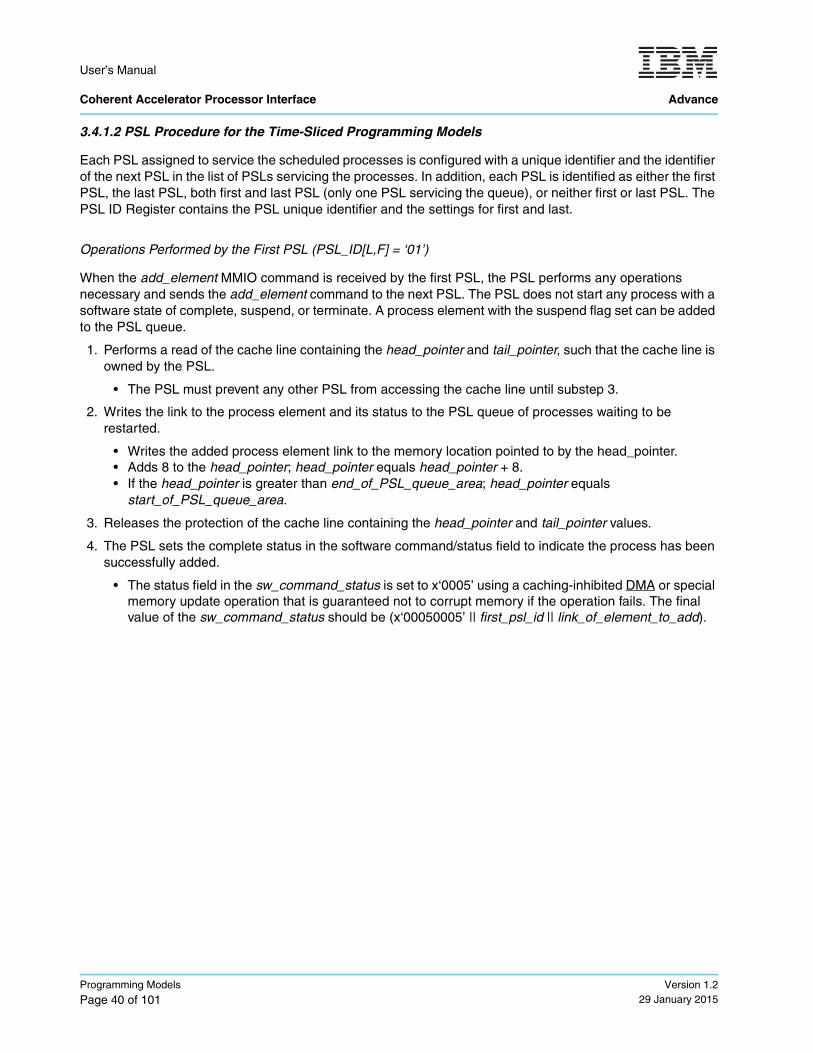
User’s Manual Coherent Accelerator Processor Interface Advance
Programming Models
Page 40 of 101Version 1.2
29 January 2015
3.4.1.2 PSL Procedure for the Time-Sliced Programming Models
Each PSL assigned to service the scheduled processes is configured with a unique identifier and the identifier of the next PSL in the list of PSLs servicing the processes. In addition, each PSL is identified as either the first PSL, the last PSL, both first and last PSL (only one PSL servicing the queue), or neither first or last PSL. The PSL ID Register contains the PSL unique identifier and the settings for first and last.
Operations Performed by the First PSL (PSL_ID[L,F] = ‘01’)
When the add_element MMIO command is received by the first PSL, the PSL performs any operations necessary and sends the add_element command to the next PSL. The PSL does not start any process with a software state of complete, suspend, or terminate. A process element with the suspend flag set can be added to the PSL queue.
1. Performs a read of the cache line containing the head_pointer and tail_pointer, such that the cache line is owned by the PSL.
• The PSL must prevent any other PSL from accessing the cache line until substep 3.
2. Writes the link to the process element and its status to the PSL queue of processes waiting to be restarted.
• Writes the added process element link to the memory location pointed to by the head_pointer.• Adds 8 to the head_pointer; head_pointer equals head_pointer + 8.• If the head_pointer is greater than end_of_PSL_queue_area; head_pointer equals
start_of_PSL_queue_area.
3. Releases the protection of the cache line containing the head_pointer and tail_pointer values.
4. The PSL sets the complete status in the software command/status field to indicate the process has been successfully added.
• The status field in the sw_command_status is set to x‘0005’ using a caching-inhibited DMA or special memory update operation that is guaranteed not to corrupt memory if the operation fails. The final value of the sw_command_status should be (x‘00050005’ || first_psl_id || link_of_element_to_add).
direct memory access
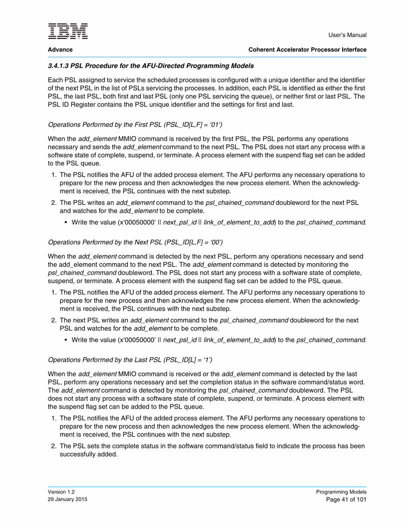
User’s Manual
Advance Coherent Accelerator Processor Interface
Version 1.229 January 2015
Programming Models
Page 41 of 101
3.4.1.3 PSL Procedure for the AFU-Directed Programming Models
Each PSL assigned to service the scheduled processes is configured with a unique identifier and the identifier of the next PSL in the list of PSLs servicing the processes. In addition, each PSL is identified as either the first PSL, the last PSL, both first and last PSL (only one PSL servicing the queue), or neither first or last PSL. The PSL ID Register contains the PSL unique identifier and the settings for first and last.
Operations Performed by the First PSL (PSL_ID[L,F] = ‘01’)
When the add_element MMIO command is received by the first PSL, the PSL performs any operations necessary and sends the add_element command to the next PSL. The PSL does not start any process with a software state of complete, suspend, or terminate. A process element with the suspend flag set can be added to the PSL queue.
1. The PSL notifies the AFU of the added process element. The AFU performs any necessary operations to prepare for the new process and then acknowledges the new process element. When the acknowledg-ment is received, the PSL continues with the next substep.
2. The PSL writes an add_element command to the psl_chained_command doubleword for the next PSL and watches for the add_element to be complete.
• Write the value (x‘00050000’ || next_psl_id || link_of_element_to_add) to the psl_chained_command.
Operations Performed by the Next PSL (PSL_ID[L,F] = ‘00’)
When the add_element command is detected by the next PSL, perform any operations necessary and send the add_element command to the next PSL. The add_element command is detected by monitoring the psl_chained_command doubleword. The PSL does not start any process with a software state of complete, suspend, or terminate. A process element with the suspend flag set can be added to the PSL queue.
1. The PSL notifies the AFU of the added process element. The AFU performs any necessary operations to prepare for the new process and then acknowledges the new process element. When the acknowledg-ment is received, the PSL continues with the next substep.
2. The next PSL writes an add_element command to the psl_chained_command doubleword for the next PSL and watches for the add_element to be complete.
• Write the value (x‘00050000’ || next_psl_id || link_of_element_to_add) to the psl_chained_command.
Operations Performed by the Last PSL (PSL_ID[L] = ‘1’)
When the add_element MMIO command is received or the add_element command is detected by the last PSL, perform any operations necessary and set the completion status in the software command/status word. The add_element command is detected by monitoring the psl_chained_command doubleword. The PSL does not start any process with a software state of complete, suspend, or terminate. A process element with the suspend flag set can be added to the PSL queue.
1. The PSL notifies the AFU of the added process element. The AFU performs any necessary operations to prepare for the new process and then acknowledges the new process element. When the acknowledg-ment is received, the PSL continues with the next substep.
2. The PSL sets the complete status in the software command/status field to indicate the process has been successfully added.
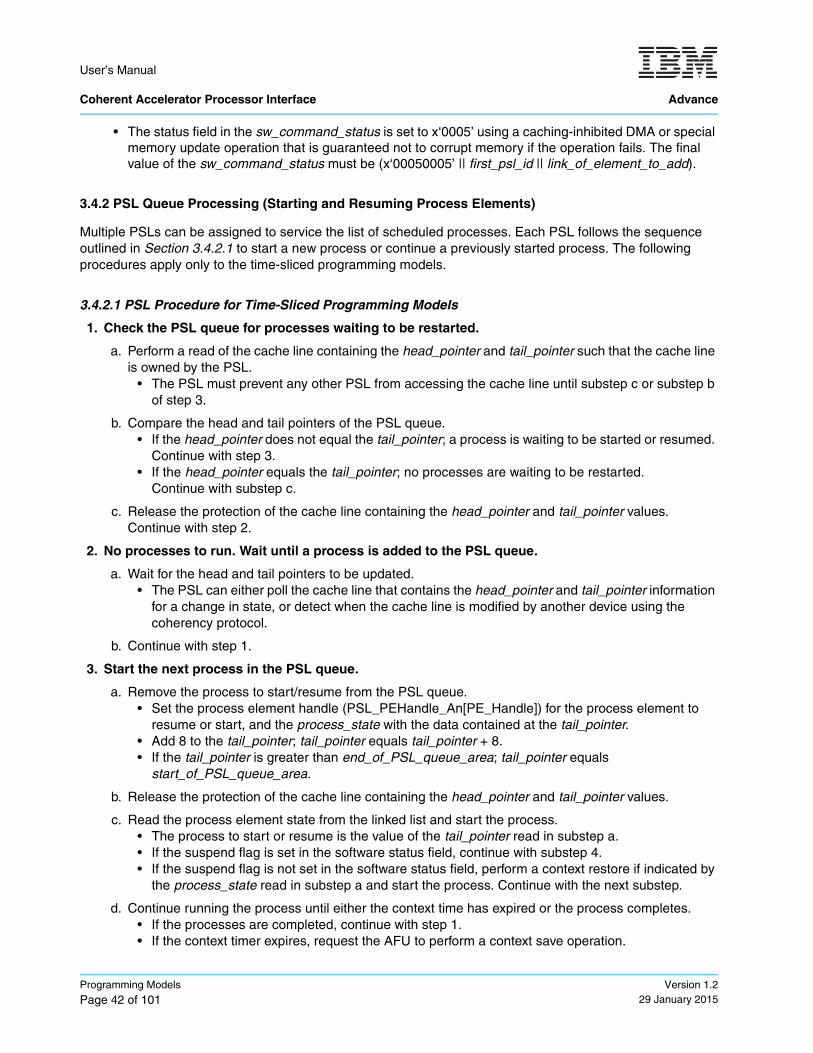
User’s Manual Coherent Accelerator Processor Interface Advance
Programming Models
Page 42 of 101Version 1.2
29 January 2015
• The status field in the sw_command_status is set to x‘0005’ using a caching-inhibited DMA or special memory update operation that is guaranteed not to corrupt memory if the operation fails. The final value of the sw_command_status must be (x‘00050005’ || first_psl_id || link_of_element_to_add).
3.4.2 PSL Queue Processing (Starting and Resuming Process Elements)
Multiple PSLs can be assigned to service the list of scheduled processes. Each PSL follows the sequence outlined in Section 3.4.2.1 to start a new process or continue a previously started process. The following procedures apply only to the time-sliced programming models.
3.4.2.1 PSL Procedure for Time-Sliced Programming Models
1. Check the PSL queue for processes waiting to be restarted.
a. Perform a read of the cache line containing the head_pointer and tail_pointer such that the cache line is owned by the PSL.
• The PSL must prevent any other PSL from accessing the cache line until substep c or substep b of step 3.
b. Compare the head and tail pointers of the PSL queue.• If the head_pointer does not equal the tail_pointer; a process is waiting to be started or resumed.
Continue with step 3.• If the head_pointer equals the tail_pointer; no processes are waiting to be restarted.
Continue with substep c.
c. Release the protection of the cache line containing the head_pointer and tail_pointer values. Continue with step 2.
2. No processes to run. Wait until a process is added to the PSL queue.
a. Wait for the head and tail pointers to be updated.• The PSL can either poll the cache line that contains the head_pointer and tail_pointer information
for a change in state, or detect when the cache line is modified by another device using the coherency protocol.
b. Continue with step 1.
3. Start the next process in the PSL queue.
a. Remove the process to start/resume from the PSL queue.• Set the process element handle (PSL_PEHandle_An[PE_Handle]) for the process element to
resume or start, and the process_state with the data contained at the tail_pointer.• Add 8 to the tail_pointer; tail_pointer equals tail_pointer + 8.• If the tail_pointer is greater than end_of_PSL_queue_area; tail_pointer equals
start_of_PSL_queue_area.
b. Release the protection of the cache line containing the head_pointer and tail_pointer values.
c. Read the process element state from the linked list and start the process.• The process to start or resume is the value of the tail_pointer read in substep a.• If the suspend flag is set in the software status field, continue with substep 4.• If the suspend flag is not set in the software status field, perform a context restore if indicated by
the process_state read in substep a and start the process. Continue with the next substep.
d. Continue running the process until either the context time has expired or the process completes.• If the processes are completed, continue with step 1.• If the context timer expires, request the AFU to perform a context save operation.
User’s Manual
Advance Coherent Accelerator Processor Interface
Version 1.229 January 2015
Programming Models
Page 43 of 101
• If a context save is performed by the AFU, wait until the operation is completed and set the process_state to indicate a context restore is required. Continue with the step 4.
4. Place the process element into the PSL queue of processes waiting to be started or resumed.
a. Perform a read of the cache line containing the head_pointer and tail_pointer such that the cache line is owned by the PSL.
• The PSL must prevent any other PSL from accessing the cache line until substep c.
b. Write the link to the process element and its status to the PSL queue of processes waiting to be restarted.
• Write the process element handle (PSL_PEHandle_An[PE_Handle]) and the process_state to the memory location pointed to by the head_pointer.
• Add 8 to the head_pointer; head_pointer equals head_pointer + 8.• If the head_pointer is greater than end_of_PSL_queue_area; head_pointer equals
start_of_PSL_queue_area.
c. Release the protection of the cache line that contains the head_pointer and tail_pointer values.
3.4.2.2 PSL Procedure for AFU-Directed Programming Models
The procedure for starting and resuming a process element in the AFU-directed programming models is implementation specific. In these models, system software adds a process element to the linked list and provides the application with a context handle. The lower 16-bits of the process handle are a pointer to the process element that contain the corresponding process state for the application. The AFU provides the lower 16-bits of the process handle (context ID) for each transaction associated with the process handle. The PSL uses the context ID to find the corresponding process element.
In the AFU-directed programming models, the PSL does not manage any queue of processes waiting to be resumed.
3.4.3 Terminating a Process Element
Under certain circumstances, system software might have to terminate a process element currently sched-uled for the AFUs. Because a scheduled process element might have already been started or is currently being executed by a PSL, system software must follow the following sequence to safely terminate a process element in the linked list of scheduled processes.
3.4.3.1 Software Procedure
The following sequence is only for a single system software process managing the linked list. Additional locking and synchronization steps are necessary to allow for multiple system software processes to concur-rently manage the linked list.
1. Set the terminate flag in the software state to ‘1’ (Software_State[T] = ‘1’).• Store x‘80000001’ to the 31st word of the process element to terminate.
2. Ensure that the terminate status is visible to all processes.• System software running on the host processor must perform a sync instruction.
3. Write a terminate_element command to the software command / status field in the linked list area.• Store (x‘00010000’ || first_psl_id || link_of_element_to_terminate) to address sw_command_status.
4. Ensure that the terminate_element command is visible to all processes.• System software running on the host processor must perform a sync instruction.
User’s Manual Coherent Accelerator Processor Interface Advance
Programming Models
Page 44 of 101Version 1.2
29 January 2015
5. Issue the terminate_element MMIO command to the first PSL.• System software performs an MMIO to the PSL Linked List Command Register with the
terminate_element command and the link of the process being terminated. (PSL_LLCMD_An = x‘000100000000’ || link_of_element_to_terminate).
6. Wait for the PSLs to complete the termination of the process element.• The process element is terminated when a load from the sw_command_status returns (x‘00010001’
|| first_psl_id || link_of_element_to_terminate).• If a value of all 1’s is returned for the status, an error has occurred. An implementation-dependent
recovery procedure must be initiated by hardware.
7. Reset the valid flag in the software state to ‘0’ (Software_State[V] = ‘0’).• Store x‘00000000’ to the 31st word of the process element to terminate.
8. Remove the process element from the linked list.• See the procedure in Section 3.4.4 Removing a Process Element from the Linked List on page 48.
3.4.3.2 PSL Procedure for Time-Sliced Programming Models
Each PSL assigned to service the scheduled processes is configured with a unique identifier and the identifier of the next PSL in the list of PSLs servicing the processes. In addition, each PSL is identified as either the first PSL, the last PSL, both first and last PSL (only one PSL servicing the queue), or neither first or last PSL. The PSL ID Register contains the PSL unique identifier and the settings for first and last.
Operations Performed by the First PSL (PSL_ID[L,F] = ‘01’)
When the terminate_element MMIO command is received by the first PSL, the PSL checks to see if the process element being terminated is currently running, performs any operations necessary, and sends the terminate_element command to the next PSL or sets the completion status in the software command/status word.
1. If the process element is running, the process is terminated. The PSL sets the complete status in the soft-ware command/status field to indicate that the process has been successfully terminated. The PSL is allowed to complete any outstanding transactions but must not start any new transactions for the process.
• The status field in the sw_command_status is set to x‘0001’ using a caching-inhibited DMA or special memory update operation that is guaranteed not to corrupt memory if the operation fails. The final value of the sw_command_status must be (x‘00010001’ || first_psl_id || link_of_element_to_terminate).
2. If the process element is not running, the PSL writes a termination command to the psl_chained_command doubleword for the next PSL and watches for the termination to be complete.
• Write the value (x‘00010000’ || next_psl_id || link_of_element_to_terminate) to the psl_chained_command.
• While waiting for the process to be terminated, the PSL does not attempt to start the corresponding process or any process with the complete, suspend, or terminate flags set. The PSL can perform other operations.
– The process is terminated when the status field in the sw_command_status is x‘0001’.
User’s Manual
Advance Coherent Accelerator Processor Interface
Version 1.229 January 2015
Programming Models
Page 45 of 101
Operations Performed by the Last PSL (PSL_ID[L,F] = ‘00’)
When the terminate_element command is detected by the next PSL, the PSL checks to see if the process element that is being terminated is currently running, performs any operations necessary, and sends the terminate_element command to the next PSL or sets the completion status in the software command/status word. The terminate_element command is detected by monitoring the psl_chained_command doubleword.
1. If the process element is running, the process is terminated. The PSL sets the complete status in the soft-ware command/status field to indicate that the process has been successfully terminated. The PSL is allowed to complete any outstanding transactions but must not start any new transactions for the process.
• The status field in the sw_command_status is set to x‘0001’ using a caching-inhibited DMA or special memory update operation that is guaranteed not to corrupt memory if the operation fails. The final value of the sw_command_status must be (x‘00010001’ || first_psl_id || link_of_element_to_terminate).
2. If the process element is not running, the PSL writes a termination command to the psl_chained_command doubleword for the next PSL and watches for the termination to be completed.
• Write the value (x‘00010000’ || next_psl_id || link_of_element_to_terminate) to the psl_chained_command.
• While waiting for the process to be terminated, the PSL does not attempt to start the correspond-ing process or any process with the complete, suspend, or terminate flags set. The PSL can per-form other operations.
– The process is terminated when the status field in the sw_command_status is x‘0001’.
Operations Performed by the Last PSL (PSL_ID[L] = ‘1’)
When the terminate_element MMIO command is received or the terminate_element command is detected by the last PSL, the PSL checks to see if the process element being terminated is currently running, performs any operations necessary, and sets the completion status in the software command/status word. The terminate_element command is detected by monitoring the psl_chained_command doubleword.
1. If the process element is running, the process is terminated and the PSL sets the complete status in the software command/status field to indicate that the process has been successfully terminated. The PSL is allowed to complete any outstanding transactions but must not start any new transactions for the process.
• The status field in the sw_command_status is set to x‘0001’ using a caching-inhibited DMA or special memory update operation that is guaranteed not to corrupt memory if the operation fails. The final value of the sw_command_status must be (x‘00010001’ || first_psl_id || link_of_element_to_terminate).
2. If the process element is not running, the PSL searches the queue to determine if the process is waiting to be resumed and indicates the process termination is complete.
• The PSL pulls each process link from the PSL queue and compares the link with the process being terminated. The full queue is searched.
(1) Performs a read of the cache line containing the head_pointer and tail_pointer such that the cache line is owned by the PSL.
– The PSL must prevent any other PSL from accessing the cache line until substep 6.
• Save the head_pointer location to an initial_head_pointer internal register.
(2) Removes the process from the PSL queue.
– Read the process_element_link and process_state pointed to by the tail_pointer.– Add 8 to the tail_pointer; tail_pointer equals tail_pointer + 8.
User’s Manual Coherent Accelerator Processor Interface Advance
Programming Models
Page 46 of 101Version 1.2
29 January 2015
– If the tail_pointer is greater than end_of_PSL_queue_area; tail_pointer equals start_of_PSL_queue_area.
(3) Compares the process_element_link read in substep 2 with link_of_element_to_terminate.
– If the links match, continue with substep 5.– If the link do not match, continue with the next substep.
(4) Puts the process_element_link and process_state back on the PSL queue.
– Writes the process_element_link and process_state to the memory location pointed to by the head_pointer.
– Add 8 to the head_pointer; head_pointer equals head_pointer + 8.– If the head_pointer is greater than end_of_PSL_queue_area; head_pointer equals
start_of_PSL_queue_area.
(5) Compares the tail_pointer to the initial_head_pointer.
– If the tail_pointer is note equal to initial_head_pointer, continue with substep 2.– If the tail_pointer is equal to initial_head_pointer, continue with the next substep.
(6) Release the protection of the cache line containing the head_pointer and tail_pointer values.
• After completing the search of all process links, the status field in the sw_command_status is set to x‘0001’ using a caching-inhibited DMA or special memory update operation that is guaranteed not to corrupt memory if the operation fails. The final value of the sw_command_status must be (x‘00010001’ || first_psl_id || link_of_element_to_terminate).
All other PSLs can now stop protecting against starting the process being terminated.
3.4.3.3 PSL Procedure for AFU-Directed Programming Models
Each PSL assigned to service the scheduled processes is configured with a unique identifier and the identifier of the next PSL in the list of PSLs servicing the processes. In addition, each PSL is identified as either the first PSL, the last PSL, both first and last PSL (only one PSL servicing the queue), or neither first or last PSL. The PSL ID Register contains the PSL unique identifier and the settings for first and last.
Operations Performed by the First PSL (PSL_ID[L,F] = ‘01’)
When the terminate_element MMIO command is received by the first PSL, the PSL checks to see if the process element being terminated is currently running, performs any operations necessary, and sends the terminate_element command to the next PSL.
1. The PSL notifies the AFU of the process element termination. The AFU performs any necessary opera-tions to remove the process and then acknowledges the termination of the process element. When the acknowledgment is received, the PSL continues with the next substep.
2. If the process is running, the process is terminated. The AFU and PSL are allowed to complete any out-standing transactions but must not start any new transactions for the process.
3. The PSL writes a termination command to the psl_chained_command doubleword for the next PSL.
• Write the value (x‘00010000’ || next_psl_id || link_of_element_to_terminate) to the psl_chained_command.
User’s Manual
Advance Coherent Accelerator Processor Interface
Version 1.229 January 2015
Programming Models
Page 47 of 101
Operations Performed by the Last PSL (PSL_ID[L,F] = ‘00’)
When the terminate_element command is detected by the next PSL, the PSL checks to see if the process element being terminated is currently running, performs any operations necessary, and sends the terminate_element command to the next PSL. The terminate_element command is detected by monitoring the psl_chained_command doubleword.
1. The PSL notifies the AFU of the process element termination. The AFU performs any necessary opera-tions to remove the process and then acknowledges the termination of the process element. When the acknowledgment is received, the PSL continues with the next substep.
2. If the process is running, the process is terminated. The AFU and PSL are allowed to complete any out-standing transactions but should not start any new transactions for the process.
3. The PSL writes a termination command to the psl_chained_command doubleword for the next PSL and watches for the termination to be complete.
• Write the value (x‘00010000’ || next_psl_id || link_of_element_to_terminate) to the psl_chained_command.
Operations Performed by the Last PSL (PSL_ID[L] = ‘1’)
When the terminate_element MMIO command is received or the terminate_element command is detected by the last PSL, the PSL checks to see if the process element that is being terminated is currently running, performs any operations necessary, and sets the completion status in the software command/status word. The terminate_element command is detected by monitoring the psl_chained_command doubleword.
1. The PSL notifies the AFU of the process element termination. The AFU performs any necessary opera-tions to remove the process and then acknowledges the termination of the process element. When the acknowledgment is received, the PSL continues with the next substep.
2. If the process is running, the process is terminated. The AFU and PSL are allowed to complete any out-standing transactions but must not start any new transactions for the process.
3. The PSL sets the complete status in the software command/status field to indicate that the process has been successfully terminated.
• The status field in the sw_command_status is set to x‘0001’ using a caching-inhibited DMA or special memory update operation that is guaranteed not to corrupt memory if the operation fails. The final value of the sw_command_status must be (x‘00010001’ || first_psl_id || link_of_element_to_terminate).
User’s Manual Coherent Accelerator Processor Interface Advance
Programming Models
Page 48 of 101Version 1.2
29 January 2015
3.4.4 Removing a Process Element from the Linked List
To make room for new process elements in the linked list, completed and terminated process elements must be removed by system software. To safely remove a process element from the linked list of scheduled processes, software must follow the sequence outlined in Section 3.4.4.1.
3.4.4.1 Software Procedure
Note: The following sequence is only for a single system-software process managing the linked list. Addi-tional locking and synchronization steps are necessary to allow for multiple system-software processes to concurrently manage the linked list.
1. Update the system-software implementation-dependent free list and process-element linked list struc-tures to reflect the removal of the process element.
2. Write a remove_element command to the software command/status field in the linked list area.
• Store (x‘00020000’ || first_psl_id || link_of_element_to_remove) to sw_command_status.
3. Ensure that the remove_element command is visible to all processes.
• System software running on the host processor must perform a sync instruction.
4. Issue the remove_element MMIO command to the first PSL.
• System software performs an MMIO to the PSL Linked List Command Register with the remove_element command and the link of the process being removed. (PSL_LLCMD_An = x‘000200000000’ || link_of_element_to_remove)
5. Wait for the PSLs to acknowledge the removal of the process element.
• The process element is terminated when a load from the sw_command_status returns (x‘00020002’ || first_psl_id || link_of_element_to_remove).
• If a value of all 1’s is returned for the status, an error has occurred. An implementation-dependent recovery procedure must be initiated by hardware.
6. Invalidate the PSL SLBs and TLBs for the processes being removed.
• System software performs an MMIO write to the Lookaside Buffer Invalidation Selector with the pro-cess ID and logical partition ID of the process being removed. (PSL_LBISEL = PID || LPID).
• System software performs an MMIO write to invalidate the SLBs (PSL_SLBIA = x‘3’).
• System software waits until the SLB invalidate is completed (MMIO read of PSL_SLBIA returns zero in the least significant bit).
• System software performs an MMIO write to invalidate the TLBs (PSL_TLBIA = x‘3’).
• System software waits until the SLB invalidate is completed (MMIO read of PSL_TLBIA returns zero in the least significant bit).
7. At this point, the memory locations for the process element that was removed can now be reused.
Implementation Note: The removal of a process element must also invalidate all cache copies of transla-tions that are associated with the process element being removed. An implementation cannot depend on system software performing TLB and SLB invalidates.
translation lookaside buffer
segment lookaside buffer
User’s Manual
Advance Coherent Accelerator Processor Interface
Version 1.229 January 2015
Programming Models
Page 49 of 101
3.4.4.2 PSL Procedure for Time-Sliced Programming Models
Operations Performed by the First PSL (PSL_ID[L,F] = ‘x1’)
When the remove_element MMIO command is received by the first PSL, the PSL sets the completion status in the software command/status word.
1. The PSL sets the complete status in the software command/status field to indicate that it is now safe to remove the process element from the linked list.
• The status field in the sw_command_status is set to x‘0002’ using a caching-inhibited DMA or special memory update operation that is guaranteed not to corrupt memory if the operation fails. The final value of the sw_command_status must be (x‘00020002’ || first_psl_id || link_of_element_to_remove).
3.4.4.3 PSL Procedure for AFU-Directed Programming Models
Operations Performed by the First PSL (PSL_ID[L,F] = ‘x1’).
When the remove_element MMIO command is received by the first PSL, the PSL notifies the AFU that the process element is being removed and sends the remove_element command to the next PSL.
1. The PSL notifies the AFU of the process element removal. The AFU performs any necessary operations to remove the process and then acknowledges the removal of the process element. When the acknowl-edgment is received, the PSL continues with the next substep.
2. The PSL sets the complete status in the software command/status field to indicate that it is now safe to remove the process element from the linked list.
• Write the value (x‘00020000’ || next_psl_id || link_of_element_to_remove) to the psl_chained_command.
• The PSL does not start any process with a software state of complete, suspend, or terminate. A pro-cess element with the suspend flag set can be added to the PSL queue.
Operations Performed by the Last PSL (PSL_ID[L,F] = ‘00’)
When the remove_element command is detected by the next PSL, the PSL notifies the AFU that the process element is being removed and sends the remove_element command to the next PSL. The remove_element command is detected by monitoring the psl_chained_command doubleword.
1. The PSL notifies the AFU of the process element removal. The AFU performs any necessary operations to remove the process and then acknowledges the removal of the process element. When the acknowl-edgment is received, the PSL continues with the next substep.
2. The PSL sets the complete status in the software command/status field to indicate that it is now safe to remove the process element from the linked list.
• Write the value (x‘00020000’ || next_psl_id || link_of_element_to_remove) to the psl_chained_command.
• The PSL does not start any process with a software state of complete, suspend, or terminate. A pro-cess element with the suspend flag set can be added to the PSL queue.
User’s Manual Coherent Accelerator Processor Interface Advance
Programming Models
Page 50 of 101Version 1.2
29 January 2015
Operations Performed by the Last PSL (PSL_ID[L] = ‘1’)
When the suspend_element MMIO command is received or the suspend_element command is detected by the last PSL, the PSL checks to see if the process element being terminated is currently running, performs any operations necessary, and sets the completion status in the software command/status word. The suspend_element command is detected by monitoring the psl_chained_command doubleword.
1. The PSL notifies the AFU of the process element removal. The AFU performs any necessary operations to remove the process and then acknowledges the removal of the process element. When the acknowl-edgment is received, the PSL continues with the next substep.
2. The PSL sets the complete status in the software command/status field to indicate that the process has been successfully removed.
• The status field in the sw_command_status is set to x‘0002’ using a caching-inhibited DMA or special memory update operation that is guaranteed not to corrupt memory if the operation fails.
3.4.5 Suspending a Process Element in the Linked List
The suspend flag in the software process element state is used to temporarily stall the processing of a process element. If the process is already running on an AFU, setting the suspend flag stops the current running process.
3.4.5.1 Software Procedure
1. Set the suspend flag in the software state to ‘1’ (Software_State[S] = ‘1’).
• Store x‘80000002’ to the 31st word of the process element to suspend.
2. Ensure that the update to the software_state is visible to all processes.
• System software running on the host processor must perform a sync instruction.
3. Write a suspend_element command to the software command / status field in the linked list area.
• Store (x‘00030000’ || first_psl_id || link_of_element_to_suspend) to sw_command_status.
4. Ensure that the suspend_element command is visible to all processes.
• System software running on the host processor must perform a sync instruction.
5. Issue the suspend_element MMIO command to the first PSL.
• System software performs an MMIO to the PSL Linked List Command Register with the suspend_element command and the link to the new process being added. (PSL_LLCMD_An = x‘000300000000’ || link_of_element_to_suspend).
6. Wait for the PSL to suspend the process element.
• The process element is suspended when a load from the sw_command_status returns (x‘00030003’ || first_psl_id || link_of_element_to_suspend).
• If a value of all 1’s is returned for the status, an error has occurred. An implementation-dependent recovery procedure must be initiated by hardware.
User’s Manual
Advance Coherent Accelerator Processor Interface
Version 1.229 January 2015
Programming Models
Page 51 of 101
3.4.5.2 PSL Procedure for Time-Sliced Programming Models
Each PSL assigned to service the scheduled processes is configured with a unique identifier and the identifier of the next PSL in the list of PSLs servicing the processes. In addition, each PSL is identified as either the first PSL, the last PSL, both first and last PSL (only one PSL servicing the queue), or neither first or last PSL. The PSL ID Register contains the PSL unique identifier and the settings for first and last.
Operations Performed by the First PSL (PSL_ID[L,F] = ‘01’)
When the suspend_element MMIO command is received by the first PSL, the PSL checks to see if the process element being suspended is currently running, performs any operations necessary, and sends the suspend_element command to the next PSL or sets the completion status in the software command/status word.
1. If the process is running, the process is suspended. The PSL sets the complete status in the software command/status field to indicate that the process has been successfully suspended. The PSL is allowed to complete any outstanding transactions but must not start any new transactions for the process.
• The status field in the sw_command_status is set to x‘0003’ using a caching-inhibited DMA or special memory update operation that is guaranteed not to corrupt memory if the operation fails. The final value of the sw_command_status must be (x‘00030003’ || first_psl_id || link_of_element_to_suspend).
2. If the process element is not running, the PSL writes a suspend command to the psl_chained_command doubleword for the next PSL.
• Write the value (x‘00030000’ || next_psl_id || link_of_element_to_suspend) to the psl_chained_command.
• The PSL does not start any process with a software state of complete, suspend, or terminate. A pro-cess element with the suspend flag set can be added to the PSL queue.
Operations Performed by the Last PSL (PSL_ID[L,F] = ‘00’)
When the suspend_element command is detected by the next PSL, the PSL checks to see if the process element being suspended is currently running, performs any operations necessary, and sends the suspend_element command to the next PSL or sets the completion status in the software command/status word. The suspend_element command is detected by monitoring the psl_chained_command doubleword.
1. If the process element is running, the process is suspended. The PSL sets the complete status in the software command/status field to indicate that the process has been successfully suspended. The PSL is allowed to complete any outstanding transactions but must not start any new transactions for the process.
• The status field in the sw_command_status is set to x‘0003’ using a caching-inhibited DMA or special memory update operation that is guaranteed not to corrupt memory if the operation fails. The final value of the sw_command_status must be (x‘00030003’ || first_psl_id || link_of_element_to_suspend).
2. If the process element is not running, the PSL writes a suspend command to the psl_chained_command doubleword for the next PSL.
• Write the value (x‘00030000’ || next_psl_id || link_of_element_to_suspend) to the psl_chained_command.
• The PSL does not start any process with a software state of complete, suspend, or terminate. A pro-cess element with the suspend flag set can be added to the PSL queue.
User’s Manual Coherent Accelerator Processor Interface Advance
Programming Models
Page 52 of 101Version 1.2
29 January 2015
Operations Performed by the Last PSL (PSL_ID[L] = ‘1’)
When the suspend_element MMIO command is received or the suspend_element command is detected by the last PSL, the PSL checks to see if the process element being terminated is currently running, performs any operations necessary, and sets the completion status in the software command/status word. The suspend_element command is detected by monitoring the psl_chained_command doubleword.
1. If the process element is running, the process is suspended. The PSL is allowed to complete any out-standing transactions but must not start any new transactions for the process.
2. The PSL sets the complete status in the software command/status field to indicate that the process has been successfully suspended.
• The status field in the sw_command_status is set to x‘0003’ using a caching-inhibited DMA or special memory update operation that is guaranteed not to corrupt memory if the operation fails. The final value of the sw_command_status must be (x‘00030003’ || first_psl_id || link_of_element_to_suspend).
• The PSL does not start any process with a software state of complete, suspend, or terminate. A pro-cess element with the suspend flag set can be added to the PSL queue.
3.4.5.3 PSL Procedure for AFU-Directed Programming Models
Each PSL assigned to service the scheduled processes is configured with a unique identifier and the identifier of the next PSL in the list of PSLs servicing the processes. In addition, each PSL is identified as either the first PSL, the last PSL, both first and last PSL (only one PSL servicing the queue), or neither first or last PSL. The PSL ID Register contains the PSL unique identifier and the settings for first and last.
Operations Performed by the First PSL (PSL_ID[L,F] = ‘01’)
When the suspend_element MMIO command is received by the first PSL, the PSL checks to see if the process element being suspended is currently running, performs any operations necessary, and sends the suspend_element command to the next PSL or sets the completion status in the software command/status word.
1. The PSL notifies the AFU of the suspended process element. The AFU performs any necessary opera-tions to suspend the process and then acknowledges the suspension of the process element. When the acknowledgment is received, the PSL continues with the next substep.
2. If the process is running, the process is suspended. The PSL sets the complete status in the software command/status field to indicate that the process has been successfully suspended. The PSL is allowed to complete any outstanding transactions but must not start any new transactions for the process.
• The status field in the sw_command_status is set to x‘0003’ using a caching-inhibited DMA or special memory update operation that is guaranteed not to corrupt memory if the operation fails. The final value of the sw_command_status must be (x‘00030003’ || first_psl_id || link_of_element_to_suspend).
3. If the process element is not running, the PSL writes a suspend command to the psl_chained_command doubleword for the next PSL.
• Write the value (x‘00030000’ || next_psl_id || link_of_element_to_suspend) to the psl_chained_command.
• The PSL does not start any process with a software state of complete, suspend, or terminate. A pro-cess element with the suspend flag set can be added to the PSL queue.
User’s Manual
Advance Coherent Accelerator Processor Interface
Version 1.229 January 2015
Programming Models
Page 53 of 101
Operations Performed by the Last PSL (PSL_ID[L,F] = ‘00’)
When the suspend_element command is detected by the next PSL, the PSL checks to see if the process element being terminated is currently running, performs any operations necessary, and sends the terminate_element command to the next PSL or sets the completion status in the software command/status word. The suspend_element command is detected by monitoring the psl_chained_command doubleword.
1. The PSL notifies the AFU of the suspended process element. The AFU performs any necessary opera-tions to suspend the process and then acknowledges the suspension of the process element. When the acknowledgment is received, the PSL continues with the next substep.
2. If the process element is running, the process is suspended. The PSL is allowed to complete any out-standing transactions but must not start any new transactions for the process.
3. The PSL writes a suspend command to the psl_chained_command doubleword for the next PSL.
• Write the value (x‘00030000’ || next_psl_id || link_of_element_to_suspend) to the psl_chained_command.
• The PSL does not start any process with a software state of complete, suspend, or terminate. A pro-cess element with the suspend flag set can be added to the PSL queue.
Operations Performed by the Last PSL (PSL_ID[L] = ‘1’)
When the suspend_element MMIO command is received or the suspend_element command is detected by the last PSL, the PSL checks to see if the process element being terminated is currently running, performs any operations necessary, and sets the completion status in the software command/status word. The suspend_element command is detected by monitoring the psl_chained_command doubleword.
1. The PSL notifies the AFU of the suspended process element. The AFU performs any necessary opera-tions to suspend the process and then acknowledges the suspension of the process element. When the acknowledgment is received, the PSL continues with the next substep.
2. If the process element is running, the process is suspended. The PSL is allowed to complete any out-standing transactions but must not start any new transactions for the process.
3. The PSL sets the complete status in the software command/status field to indicate the process has been successfully suspended.
• The status field in the sw_command_status is set to x‘0003’ using a caching-inhibited DMA or special memory update operation that is guaranteed not to corrupt memory if the operation fails. The final value of the sw_command_status must be (x‘00030003’ || first_psl_id || link_of_element_to_suspend).
• The PSL does not start any process with a software state of complete, suspend, or terminate. A pro-cess element with the suspend flag set can be added to the PSL queue.
User’s Manual Coherent Accelerator Processor Interface Advance
Programming Models
Page 54 of 101Version 1.2
29 January 2015
3.4.6 Resume a Process Element
The resume process element procedure is used to restart the execution of an process element after the process has been suspended.
3.4.6.1 Software Procedure
1. Reset the suspend flag in the software state to ‘0’ (Software_State[S] = ‘0’).
• Store x‘80000000’ to the 31st word of the process element to suspend.
2. Ensure that the update to the software_state is visible to all processes.
• System software running on the host processor must perform a sync instruction.
3. Write the resume_element command to the software command/status field in the linked list area.
• Store (x‘00040000’ || first_psl_id || link_of_element_to_resume) to sw_command_status.
4. Ensure that the resume_element command is visible to all processes.
• System software running on the host processor must perform a sync instruction.
5. Issue the resume_element MMIO command to the first PSL.
• System software performs an MMIO to the PSL Linked List Command Register with the update_element command and the link to the new process being added. (PSL_LLCMD_An = x‘000400000000’ || link_of_element_to_resume).
6. Wait for the PSLs to acknowledge the update of the process element.
• The process element is updated when a load from the sw_command_status returns (x‘00040004’ || first_psl_id || link_of_element_to_resume).
• If a value of all 1’s is returned for the status, an error has occurred. An implementation-dependent recovery must be initiated by hardware.
3.4.6.2 PSL Procedure for Time-Sliced and AFU-Directed Programming Models
Each PSL assigned to service the scheduled processes is configured with a unique identifier and the identifier of the next PSL in the list of PSLs servicing the processes. In addition, each PSL is identified as either the first PSL, the last PSL, both first and last PSL (only one PSL servicing the queue), or neither first or last PSL. The PSL ID Register contains the PSL unique identifier and the settings for first and last.
Operations Performed by the First PSL (PSL_ID[L,F] = ‘01’)
When the resume_element MMIO command is received by the first PSL, the PSL performs any operations necessary and sends the resume_element command to the next PSL. The PSL does not start any process with a software state of complete, suspend, or terminate. A process element with the suspend flag set can be added to the PSL queue.
1. When operating in an AFU-directed programming model, the PSL notifies the AFU of the process ele-ment being resumed. The AFU performs any necessary operations to resume execution of the process and then acknowledges the resumed process element. When the acknowledgment is received, the PSL continues with the next substep. The AFU is not notified of the added process element for all other pro-gramming models.
User’s Manual
Advance Coherent Accelerator Processor Interface
Version 1.229 January 2015
Programming Models
Page 55 of 101
2. The PSL writes an resume_element command to the psl_chained_command doubleword for the next PSL.
• Write the value (x‘00040000’ || next_psl_id || link_of_element_to_resume) to the psl_chained_command.
Operations Performed by the Next PSL (PSL_ID[L,F] = ‘00’)
When the resume_element command is detected by the next PSL, perform any operations necessary and send the add_element command to the next PSL. The resume_element command is detected by monitoring the psl_chained_command doubleword. The PSL does not start any process with a software state of complete, suspend, or terminate. A process element with the suspend flag set can be added to the PSL queue.
1. When operating in an AFU-directed programming model, the PSL notifies the AFU of the process ele-ment being resumed. The AFU performs any necessary operations to resume execution of the process and then acknowledges the resumed process element. When the acknowledgment is received, the PSL continues with the next substep. The AFU is not notified of the added process element for all other pro-gramming models.
2. The PSL writes an resume_element command to the psl_chained_command doubleword for the next PSL.
• Write the value (x‘00040000’ || next_psl_id || link_of_element_to_resume) to the psl_chained_command.
Operations Performed by the Last PSL (PSL_ID[L] = ‘1’)
When the resume_element MMIO command is received or the resume_element command is detected by the last PSL, perform any operations necessary and set the completion status in the software command/status word. The resume_element command is detected by monitoring the psl_chained_command doubleword. The PSL does not start any process with a software state of complete, suspend, or terminate. A process element with the suspend flag set can be added to the PSL queue.
1. When operating in an AFU-directed programming model, the PSL notifies the AFU of the process ele-ment being resumed. The AFU performs any necessary operations to resume execution of the process and then acknowledges the resumed process element. When the acknowledgment is received, the PSL continues with the next substep. The AFU is not notified of the added process element for all other pro-gramming models.
2. The PSL sets the complete status in the software command/status field to indicate that the process has been successfully resumed.
• The status field in the sw_command_status is set to x‘0004’ using a caching-inhibited DMA or special memory update operation that is guaranteed not to corrupt memory if the operation fails. The final value of the sw_command_status must be (x‘00040004’ || first_psl_id || link_of_element_to_resume).
User’s Manual Coherent Accelerator Processor Interface Advance
Programming Models
Page 56 of 101Version 1.2
29 January 2015
3.4.7 Updating a Process Element in the Linked List
The update flag in the software process element state is use to update the state of a process element. This command causes the PSL to invalidate any non-coherent copies of the process element that might be cached and read a new copy from system memory. If the update of the process element is required to be atomic, the process element must be suspended before the update is made (suspend, update, resume).
3.4.7.1 Software Procedure
1. Write the update_element command to the software command/status field in the linked list area.
• Store (x‘00060000’ || first_psl_id || link_of_element_to_update) to sw_command_status.
2. Ensure that the update_element command is visible to all processes.
• System software running on the host processor must perform a sync instruction.
3. Issue the update_element MMIO command to the first PSL.
• System software performs an MMIO to the PSL Linked List Command Register with the update_element command and the link to the new process being added. (PSL_LLCMD_An = x‘000600000000’ || link_of_element_to_update).
4. Wait for the PSL to acknowledge the update of the process element.
• The process element is updated when a load from the sw_command_status returns (x‘00060006’ || first_psl_id || link_of_element_to_update).
• If a value of all 1’s is returned for the status, an error has occurred. An implementation-dependent recovery procedure must be initiated by hardware.

User’s Manual
Advance Coherent Accelerator Processor Interface
Version 1.229 January 2015
Programming Models
Page 57 of 101
3.4.7.2 PSL Procedure for Time-Sliced and AFU-Directed Programming Models
Each PSL assigned to service the scheduled processes is configured with a unique identifier and the identifier of the next PSL in the list of PSLs servicing the processes. In addition, each PSL is identified as either the first PSL, the last PSL, both first and last PSL (only one PSL servicing the queue), or neither first or last PSL. The PSL ID Register contains the PSL unique identifier and the settings for first and last.
Operations Performed by the First PSL (PSL_ID[L,F] = ‘01’)
When the update_element MMIO command is received by the first PSL, the PSL checks to see if the process element being updated is currently running, performs any operations necessary, and sends the update_element command to the next PSL.
1. When operating in an AFU-directed programming model, the PSL notifies the AFU of the updated pro-cess element. The AFU performs any necessary operations to update the process and then acknowl-edges the updated process element. When the acknowledgment is received, the PSL continues with the next substep. The AFU is not notified of the added process element for all other programming models.
2. If the process is running, the PSL completes any outstanding transactions and does not start any new transactions for the process. The PSL then invalidate the process element state and refetches a new copy from the process element linked list in system memory. If the process element is coherently cached, the update is automatically handled by the coherency protocol.
• The status field in the sw_command_status is set to x‘0006’ using a caching-inhibited DMA or special memory update operation that is guaranteed not to corrupt memory if the operation fails. The final value of the sw_command_status must be (x‘00060006’ || first_psl_id || link_of_element_to_update).
• The PSL does not start any process with a software state of complete, suspend, or terminate. A pro-cess element with the suspend flag set can be added to the PSL queue.
3. If the process element is not running, the PSL writes a update command to the psl_chained_command doubleword for the next PSL.
• Write the value (x‘00060000’ || next_psl_id || link_of_element_to_update) to the psl_chained_command.
• The PSL does not start any process with a software state of complete, suspend, or terminate. A pro-cess element with the suspend flag set can be added to the PSL queue.
Operations Performed by the Last PSL (PSL_ID[L,F] = ‘00’)
When the update_element command is detected by the next PSL, the PSL checks to see if the process element being updated is currently running, performs any operations necessary, and sends the terminate_element command to the next PSL or sets the completion status in the software command/status word. The update_element command is detected by monitoring the psl_chained_command doubleword.
1. When operating in an AFU-directed programming model, the PSL notifies the AFU of the updated pro-cess element. The AFU performs any necessary operations to update the process and then acknowl-edges the updated process element. When the acknowledgment is received, the PSL continues with the next substep. The AFU is not notified of the added process element for all other programming models.
2. If the process is running, the PSL completes any outstanding transactions and does not start any new transactions for the process. The PSL then invalidates the process element state and refetches a new copy from the process element linked list in system memory. If the process element is coherently cached, the update is automatically handled by the coherency protocol.
User’s Manual Coherent Accelerator Processor Interface Advance
Programming Models
Page 58 of 101Version 1.2
29 January 2015
• The status field in the sw_command_status is set to x‘0006’ using a caching-inhibited DMA or special memory update operation that is guaranteed not to corrupt memory if the operation fails. The final value of the sw_command_status should be (x‘00060006’ || first_psl_id || link_of_element_to_update).
• The PSL does not start any process with a software state of complete, suspend, or terminate. A pro-cess element with the suspend flag set can be added to the PSL queue.
3. If the process element is not running, the PSL writes a suspend command to the psl_chained_command doubleword for the next PSL.
• Write the value (x‘00060000’ || next_psl_id || link_of_element_to_terminate) to the psl_chained_command.
• The PSL does not start any process with a software state of complete, suspend, or terminate. A pro-cess element with the suspend flag set can be added to the PSL queue.
Operations Performed by the Last PSL (PSL_ID[L] = ‘1’)
When the update_element MMIO command is received or the update_element command is detected by the last PSL, the PSL checks to see if the process element being terminated is currently running, performs any operations necessary, and sets the completion status in the software command/status word. The suspend_element command is detected by monitoring the psl_chained_command doubleword.
1. When operating in an AFU-directed programming model, the PSL notifies the AFU of the updated pro-cess element. The AFU performs any necessary operations to update the process and then acknowl-edges the updated process element. When the acknowledgment is received, the PSL continues with the next substep. The AFU is not notified of the added process element for all other programming models.
2. If the process is running, the PSL completes any outstanding transactions and does not start any new transactions for the process. The PSL then invalidate the process element state and refetches a new copy from the process element linked list in system memory. If the process element is coherently cached, the update is automatically handled by the coherency protocol.
• The PSL does not start any process with a software state of complete, suspend, or terminate. A pro-cess element with the suspend flag set can be added to the PSL queue.
3. The PSL sets the complete status in the software command/status field to indicate the process has been successfully suspended.
• The status field in the sw_command_status is set to x‘0006’ using a caching-inhibited DMA or special memory update operation that is guaranteed not to corrupt memory if the operation fails. The final value of the sw_command_status must be (x‘00060006’ || first_psl_id || link_of_element_to_update).
• The PSL does not start any process with a software state of complete, suspend, or terminate. A pro-cess element with the suspend flag set can be added to the PSL queue.
User’s Manual
Advance Coherent Accelerator Processor Interface
Version 1.229 January 2015
AFU Descriptor Overview
Page 59 of 101
4. AFU Descriptor Overview
A CAIA-compliant device can support programmable AFUs. The AFU descriptor is a set of registers within the problem state area that contains information about the capabilities of the AFU that is required by system soft-ware. The AFU descriptor also contains a standard format for reporting errors to system software. All AFUs must implement an AFU descriptor.
4.1 AFU Descriptor Format
The length of the AFU descriptor is implementation specific. All accesses to the AFU descriptor, including the AFU configuration record, must be either 32-bit or 64-bit operations.
The AFU descriptor provides system software with information specific to the AFU. The AFU descriptor also provides a mechanism for assigning regions of the problem state area to system processes attached to the AFU. The assignment is based on the process handle or on the offset of the process element in the linked list. The region assigned to a process handle of x‘0’ corresponds to the beginning of the AFU per-process problem state area (that is, the area starting at the AFU_PSA_offset within the problem state area). The region assigned to a process handle of “n” corresponds to the problem state area starting at AFU_PSA_offset + (n × AFU_PSA_length × 4096); where 0 ≤ n ≤ (num_of_processes - 1).
Note: In this version, only one process is supported (dedicated mode only).
The AFU descriptor contains AFU configuration records that provide system software with the information that is typically provided by the PCIe configuration space if the AFU was a PCIe device. The format of the AFU configuration record can either be the standard 256-byte configuration space or the extended 4 KB configuration space defined by the PCIe specification. If multiple AFU configuration records exist, each record corresponds to a physical function of the AFU. The AFU configuration record space is defined in little-endian format to conform to the PCIe standard.
Note: The length of each configuration record is selectable in 256-byte blocks. The AFU does not have to reserve a full 4 KB for the extended configuration space.
The AFU descriptor also contains an AFU error buffer. The AFU error buffer is intended to be used by the AFU to report application-specific errors. This data can be collected by system software and combined with adapter error data to use in creating error logs or other problem determination.
Note: Some operating systems have a base page size of 64 KB. To be compatible with a base page size of 64 KB, the AFU_PSA_offset must start on a 64 KB boundary and the AFU_PSA_length must also be a multi-ple of 64 KB. For implementation requirements on the alignment and size of the problem state area, refer to the design guides for the target operating system.
Coherent Accelerator Interface Architecture
accelerator functional unit
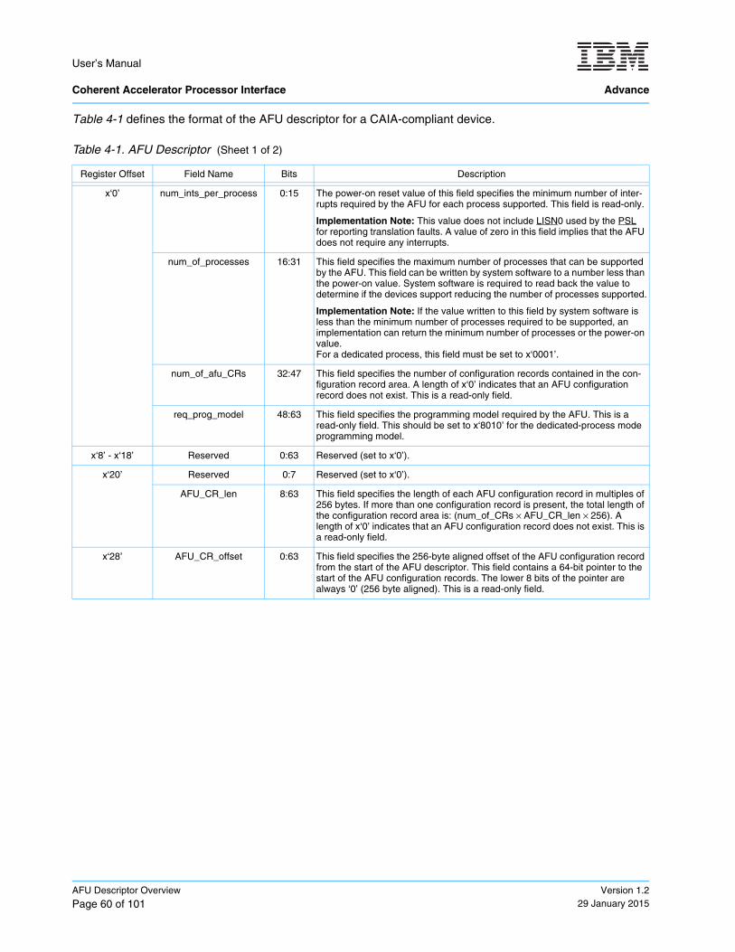
User’s Manual Coherent Accelerator Processor Interface Advance
AFU Descriptor Overview
Page 60 of 101Version 1.2
29 January 2015
Table 4-1 defines the format of the AFU descriptor for a CAIA-compliant device.
Table 4-1. AFU Descriptor (Sheet 1 of 2)
Register Offset Field Name Bits Description
x‘0’ num_ints_per_process 0:15 The power-on reset value of this field specifies the minimum number of inter-rupts required by the AFU for each process supported. This field is read-only.
Implementation Note: This value does not include LISN0 used by the PSL for reporting translation faults. A value of zero in this field implies that the AFU does not require any interrupts.
num_of_processes 16:31 This field specifies the maximum number of processes that can be supported by the AFU. This field can be written by system software to a number less than the power-on value. System software is required to read back the value to determine if the devices support reducing the number of processes supported.
Implementation Note: If the value written to this field by system software is less than the minimum number of processes required to be supported, an implementation can return the minimum number of processes or the power-on value.For a dedicated process, this field must be set to x‘0001’.
num_of_afu_CRs 32:47 This field specifies the number of configuration records contained in the con-figuration record area. A length of x‘0’ indicates that an AFU configuration record does not exist. This is a read-only field.
req_prog_model 48:63 This field specifies the programming model required by the AFU. This is a read-only field. This should be set to x‘8010’ for the dedicated-process mode programming model.
x‘8’ - x‘18’ Reserved 0:63 Reserved (set to x‘0’).
x‘20’ Reserved 0:7 Reserved (set to x‘0’).
AFU_CR_len 8:63 This field specifies the length of each AFU configuration record in multiples of 256 bytes. If more than one configuration record is present, the total length of the configuration record area is: (num_of_CRs × AFU_CR_len × 256). A length of x‘0’ indicates that an AFU configuration record does not exist. This is a read-only field.
x‘28’ AFU_CR_offset 0:63 This field specifies the 256-byte aligned offset of the AFU configuration record from the start of the AFU descriptor. This field contains a 64-bit pointer to the start of the AFU configuration records. The lower 8 bits of the pointer are always ‘0’ (256 byte aligned). This is a read-only field.
POWER service layer
logical interrupt service number
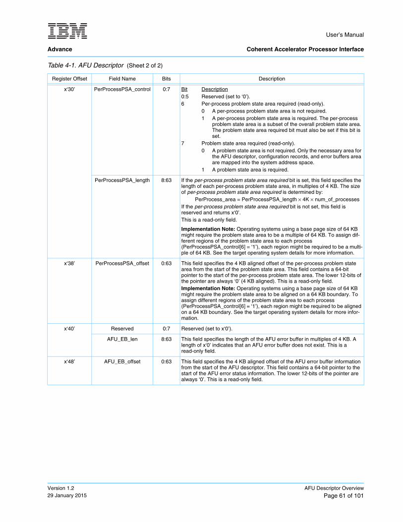
User’s Manual
Advance Coherent Accelerator Processor Interface
Version 1.229 January 2015
AFU Descriptor Overview
Page 61 of 101
x‘30’ PerProcessPSA_control 0:7 Bit Description0:5 Reserved (set to ‘0’). 6 Per-process problem state area required (read-only).
0 A per-process problem state area is not required. 1 A per-process problem state area is required. The per-process
problem state area is a subset of the overall problem state area. The problem state area required bit must also be set if this bit is set.
7 Problem state area required (read-only).0 A problem state area is not required. Only the necessary area for
the AFU descriptor, configuration records, and error buffers area are mapped into the system address space.
1 A problem state area is required.
PerProcessPSA_length 8:63 If the per-process problem state area required bit is set, this field specifies the length of each per-process problem state area, in multiples of 4 KB. The size of per-process problem state area required is determined by:
PerProcess_area = PerProcessPSA_length × 4K × num_of_processesIf the per-process problem state area required bit is not set, this field is reserved and returns x‘0’. This is a read-only field.
Implementation Note: Operating systems using a base page size of 64 KB might require the problem state area to be a multiple of 64 KB. To assign dif-ferent regions of the problem state area to each process (PerProcessPSA_control[6] = ‘1’), each region might be required to be a multi-ple of 64 KB. See the target operating system details for more information.
x‘38’ PerProcessPSA_offset 0:63 This field specifies the 4 KB aligned offset of the per-process problem state area from the start of the problem state area. This field contains a 64-bit pointer to the start of the per-process problem state area. The lower 12-bits of the pointer are always ‘0’ (4 KB aligned). This is a read-only field.Implementation Note: Operating systems using a base page size of 64 KB might require the problem state area to be aligned on a 64 KB boundary. To assign different regions of the problem state area to each process (PerProcessPSA_control[6] = ‘1’), each region might be required to be aligned on a 64 KB boundary. See the target operating system details for more infor-mation.
x‘40’ Reserved 0:7 Reserved (set to x‘0’).
AFU_EB_len 8:63 This field specifies the length of the AFU error buffer in multiples of 4 KB. A length of x‘0’ indicates that an AFU error buffer does not exist. This is a read-only field.
x‘48’ AFU_EB_offset 0:63 This field specifies the 4 KB aligned offset of the AFU error buffer information from the start of the AFU descriptor. This field contains a 64-bit pointer to the start of the AFU error status information. The lower 12-bits of the pointer are always ‘0’. This is a read-only field.
Table 4-1. AFU Descriptor (Sheet 2 of 2)
Register Offset Field Name Bits Description

User’s Manual Coherent Accelerator Processor Interface Advance
AFU Descriptor Overview
Page 62 of 101Version 1.2
29 January 2015
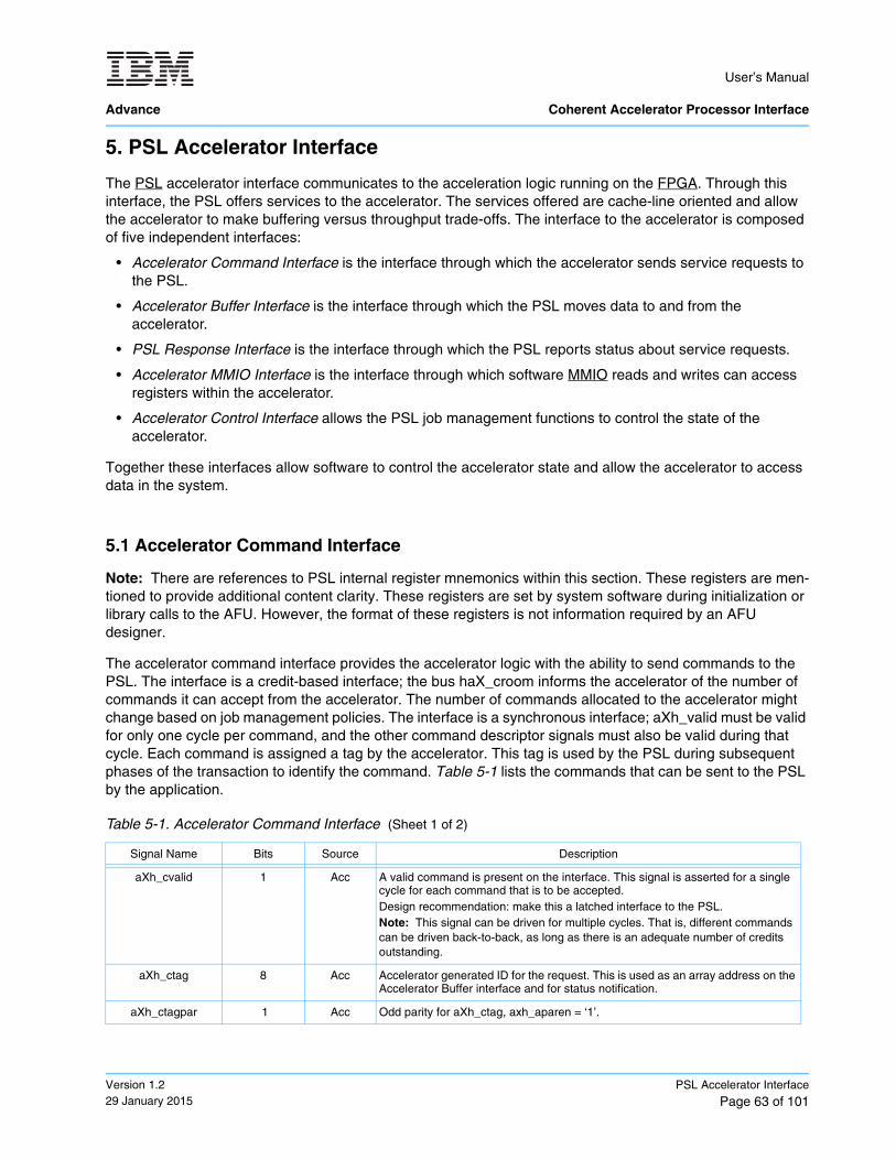
User’s Manual
Advance Coherent Accelerator Processor Interface
Version 1.229 January 2015
PSL Accelerator Interface
Page 63 of 101
5. PSL Accelerator Interface
The PSL accelerator interface communicates to the acceleration logic running on the FPGA. Through this interface, the PSL offers services to the accelerator. The services offered are cache-line oriented and allow the accelerator to make buffering versus throughput trade-offs. The interface to the accelerator is composed of five independent interfaces:
• Accelerator Command Interface is the interface through which the accelerator sends service requests to the PSL.
• Accelerator Buffer Interface is the interface through which the PSL moves data to and from the accelerator.
• PSL Response Interface is the interface through which the PSL reports status about service requests.
• Accelerator MMIO Interface is the interface through which software MMIO reads and writes can access registers within the accelerator.
• Accelerator Control Interface allows the PSL job management functions to control the state of the accelerator.
Together these interfaces allow software to control the accelerator state and allow the accelerator to access data in the system.
5.1 Accelerator Command Interface
Note: There are references to PSL internal register mnemonics within this section. These registers are men-tioned to provide additional content clarity. These registers are set by system software during initialization or library calls to the AFU. However, the format of these registers is not information required by an AFU designer.
The accelerator command interface provides the accelerator logic with the ability to send commands to the PSL. The interface is a credit-based interface; the bus haX_croom informs the accelerator of the number of commands it can accept from the accelerator. The number of commands allocated to the accelerator might change based on job management policies. The interface is a synchronous interface; aXh_valid must be valid for only one cycle per command, and the other command descriptor signals must also be valid during that cycle. Each command is assigned a tag by the accelerator. This tag is used by the PSL during subsequent phases of the transaction to identify the command. Table 5-1 lists the commands that can be sent to the PSL by the application.
Table 5-1. Accelerator Command Interface (Sheet 1 of 2)
Signal Name Bits Source Description
aXh_cvalid 1 Acc A valid command is present on the interface. This signal is asserted for a single cycle for each command that is to be accepted. Design recommendation: make this a latched interface to the PSL.Note: This signal can be driven for multiple cycles. That is, different commands can be driven back-to-back, as long as there is an adequate number of credits outstanding.
aXh_ctag 8 Acc Accelerator generated ID for the request. This is used as an array address on the Accelerator Buffer interface and for status notification.
aXh_ctagpar 1 Acc Odd parity for aXh_ctag, axh_aparen = ‘1’.
POWER service layer
field-programmable gate array
memory-mapped I/O
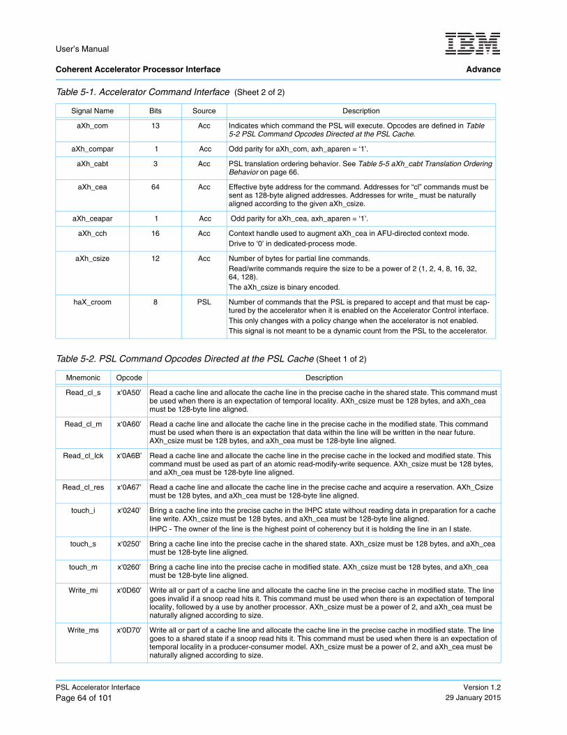
User’s Manual Coherent Accelerator Processor Interface Advance
PSL Accelerator Interface
Page 64 of 101Version 1.2
29 January 2015
aXh_com 13 Acc Indicates which command the PSL will execute. Opcodes are defined in Table 5-2 PSL Command Opcodes Directed at the PSL Cache.
aXh_compar 1 Acc Odd parity for aXh_com, axh_aparen = ‘1’.
aXh_cabt 3 Acc PSL translation ordering behavior. See Table 5-5 aXh_cabt Translation Ordering Behavior on page 66.
aXh_cea 64 Acc Effective byte address for the command. Addresses for “cl” commands must be sent as 128-byte aligned addresses. Addresses for write_ must be naturally aligned according to the given aXh_csize.
aXh_ceapar 1 Acc Odd parity for aXh_cea, axh_aparen = ‘1’.
aXh_cch 16 Acc Context handle used to augment aXh_cea in AFU-directed context mode.Drive to ‘0’ in dedicated-process mode.
aXh_csize 12 Acc Number of bytes for partial line commands. Read/write commands require the size to be a power of 2 (1, 2, 4, 8, 16, 32, 64, 128).The aXh_csize is binary encoded.
haX_croom 8 PSL Number of commands that the PSL is prepared to accept and that must be cap-tured by the accelerator when it is enabled on the Accelerator Control interface.This only changes with a policy change when the accelerator is not enabled.This signal is not meant to be a dynamic count from the PSL to the accelerator.
Table 5-2. PSL Command Opcodes Directed at the PSL Cache (Sheet 1 of 2)
Mnemonic Opcode Description
Read_cl_s x‘0A50’ Read a cache line and allocate the cache line in the precise cache in the shared state. This command must be used when there is an expectation of temporal locality. AXh_csize must be 128 bytes, and aXh_cea must be 128-byte line aligned.
Read_cl_m x‘0A60’ Read a cache line and allocate the cache line in the precise cache in the modified state. This command must be used when there is an expectation that data within the line will be written in the near future. AXh_csize must be 128 bytes, and aXh_cea must be 128-byte line aligned.
Read_cl_lck x‘0A6B’ Read a cache line and allocate the cache line in the precise cache in the locked and modified state. This command must be used as part of an atomic read-modify-write sequence. AXh_csize must be 128 bytes, and aXh_cea must be 128-byte line aligned.
Read_cl_res x‘0A67’ Read a cache line and allocate the cache line in the precise cache and acquire a reservation. AXh_Csize must be 128 bytes, and aXh_cea must be 128-byte line aligned.
touch_i x‘0240’ Bring a cache line into the precise cache in the IHPC state without reading data in preparation for a cache line write. AXh_csize must be 128 bytes, and aXh_cea must be 128-byte line aligned.IHPC - The owner of the line is the highest point of coherency but it is holding the line in an I state.
touch_s x‘0250’ Bring a cache line into the precise cache in the shared state. AXh_csize must be 128 bytes, and aXh_cea must be 128-byte line aligned.
touch_m x‘0260’ Bring a cache line into the precise cache in modified state. AXh_csize must be 128 bytes, and aXh_cea must be 128-byte line aligned.
Write_mi x‘0D60’ Write all or part of a cache line and allocate the cache line in the precise cache in modified state. The line goes invalid if a snoop read hits it. This command must be used when there is an expectation of temporal locality, followed by a use by another processor. AXh_csize must be a power of 2, and aXh_cea must be naturally aligned according to size.
Write_ms x‘0D70’ Write all or part of a cache line and allocate the cache line in the precise cache in modified state. The line goes to a shared state if a snoop read hits it. This command must be used when there is an expectation of temporal locality in a producer-consumer model. AXh_csize must be a power of 2, and aXh_cea must be naturally aligned according to size.
Table 5-1. Accelerator Command Interface (Sheet 2 of 2)
Signal Name Bits Source Description
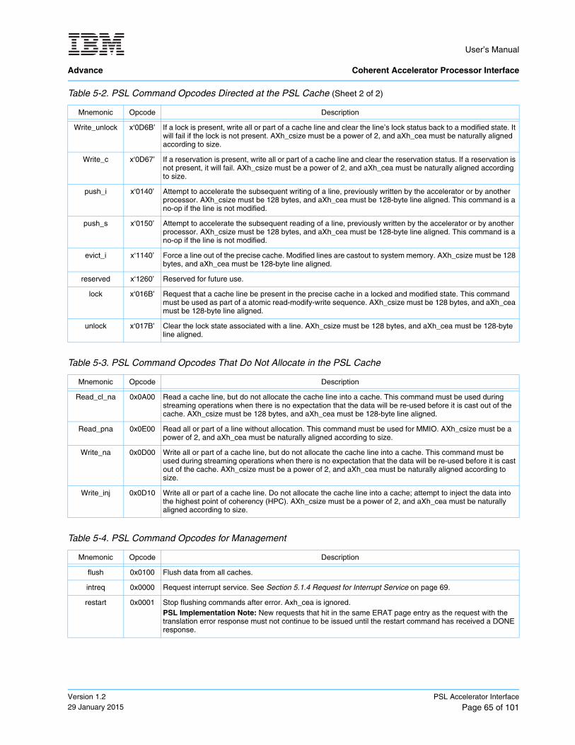
User’s Manual
Advance Coherent Accelerator Processor Interface
Version 1.229 January 2015
PSL Accelerator Interface
Page 65 of 101
Write_unlock x‘0D6B’ If a lock is present, write all or part of a cache line and clear the line’s lock status back to a modified state. It will fail if the lock is not present. AXh_csize must be a power of 2, and aXh_cea must be naturally aligned according to size.
Write_c x‘0D67’ If a reservation is present, write all or part of a cache line and clear the reservation status. If a reservation is not present, it will fail. AXh_csize must be a power of 2, and aXh_cea must be naturally aligned according to size.
push_i x‘0140’ Attempt to accelerate the subsequent writing of a line, previously written by the accelerator or by another processor. AXh_csize must be 128 bytes, and aXh_cea must be 128-byte line aligned. This command is a no-op if the line is not modified.
push_s x‘0150’ Attempt to accelerate the subsequent reading of a line, previously written by the accelerator or by another processor. AXh_csize must be 128 bytes, and aXh_cea must be 128-byte line aligned. This command is a no-op if the line is not modified.
evict_i x‘1140’ Force a line out of the precise cache. Modified lines are castout to system memory. AXh_csize must be 128 bytes, and aXh_cea must be 128-byte line aligned.
reserved x‘1260’ Reserved for future use.
lock x‘016B’ Request that a cache line be present in the precise cache in a locked and modified state. This command must be used as part of a atomic read-modify-write sequence. AXh_csize must be 128 bytes, and aXh_cea must be 128-byte line aligned.
unlock x‘017B’ Clear the lock state associated with a line. AXh_csize must be 128 bytes, and aXh_cea must be 128-byte line aligned.
Table 5-3. PSL Command Opcodes That Do Not Allocate in the PSL Cache
Mnemonic Opcode Description
Read_cl_na 0x0A00 Read a cache line, but do not allocate the cache line into a cache. This command must be used during streaming operations when there is no expectation that the data will be re-used before it is cast out of the cache. AXh_csize must be 128 bytes, and aXh_cea must be 128-byte line aligned.
Read_pna 0x0E00 Read all or part of a line without allocation. This command must be used for MMIO. AXh_csize must be a power of 2, and aXh_cea must be naturally aligned according to size.
Write_na 0x0D00 Write all or part of a cache line, but do not allocate the cache line into a cache. This command must be used during streaming operations when there is no expectation that the data will be re-used before it is cast out of the cache. AXh_csize must be a power of 2, and aXh_cea must be naturally aligned according to size.
Write_inj 0x0D10 Write all or part of a cache line. Do not allocate the cache line into a cache; attempt to inject the data into the highest point of coherency (HPC). AXh_csize must be a power of 2, and aXh_cea must be naturally aligned according to size.
Table 5-4. PSL Command Opcodes for Management
Mnemonic Opcode Description
flush 0x0100 Flush data from all caches.
intreq 0x0000 Request interrupt service. See Section 5.1.4 Request for Interrupt Service on page 69.
restart 0x0001 Stop flushing commands after error. Axh_cea is ignored.PSL Implementation Note: New requests that hit in the same ERAT page entry as the request with the translation error response must not continue to be issued until the restart command has received a DONE response.
Table 5-2. PSL Command Opcodes Directed at the PSL Cache (Sheet 2 of 2)
Mnemonic Opcode Description
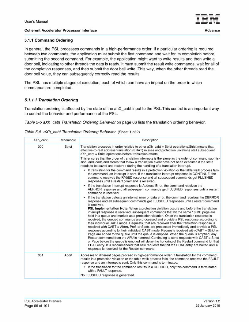
User’s Manual Coherent Accelerator Processor Interface Advance
PSL Accelerator Interface
Page 66 of 101Version 1.2
29 January 2015
5.1.1 Command Ordering
In general, the PSL processes commands in a high-performance order. If a particular ordering is required between two commands, the application must submit the first command and wait for its completion before submitting the second command. For example, the application might want to write results and then write a door bell, indicating to other threads the data is ready. It must submit the result write commands, wait for all of the completion responses, and then submit the door bell write. This way, when the other threads read the door bell value, they can subsequently correctly read the results.
The PSL has multiple stages of execution, each of which can have an impact on the order in which commands are completed.
5.1.1.1 Translation Ordering
Translation ordering is affected by the state of the ahX_cabt input to the PSL.This control is an important way to control the behavior and performance of the PSL.
Table 5-5 aXh_cabt Translation Ordering Behavior on page 66 lists the translation ordering behavior.
Table 5-5. aXh_cabt Translation Ordering Behavior (Sheet 1 of 2)
aXh_cabt Mnemonic Description
000 Strict Translation proceeds in order relative to other aXh_cabt = Strict operations.Strict means that effective-to-real address translation (ERAT) misses and protection violations stall subsequent aXh_cabt = Strict operations before translation efforts.This ensures that the order of translation interrupts is the same as the order of command submis-sion; and loads and stores that follow a translation event have not been executed if the state needs to be saved and restored during the handling of a translation interrupt.
• If translation for the command results in a protection violation or the table walk process fails the command, an interrupt is sent. If the translation interrupt response is CONTINUE, the command receives the PAGED response and all subsequent commands get FLUSHED responses until a restart command is received.
• If the translation interrupt response is Address Error, the command receives the AERROR response and all subsequent commands get FLUSHED responses until a restart command is received.
• If the translation detects an internal error or data error, the command receives the DERROR response and all subsequent commands get FLUSHED responses until a restart command is received. PSL Implementation Note: When a protection violation occurs and before the translation interrupt response is received, subsequent commands that hit the same 16 MB page are held in a queue and marked as a protection violation. Once the translation response is received, the queued commands are processed and provide a PSL response according to their individual CABT mode. Requests, that are received after the translation response is received with CABT = Abort, Pref, or Spec, are processed immediately and provide a PSL response according to their individual CABT mode. Requests received with CABT = Strict or Page are added to the queue until the queue is emptied. When the queue is emptied, any Restart command from the AFU is honored. Continuing to send requests with CABT = Strict or Page before the queue is emptied will delay the honoring of the Restart command for that ERAT entry. It is recommended that new requests that hit the ERAT entry are halted until a response is received for the Restart command.
001 Abort Accesses to different pages proceed in high-performance order. If translation for the command results in a protection violation or the table walk process fails, the command receives the FAULT response and an interrupt is sent. Only this command is terminated.
• If the translation for the command results in a DERROR, only this command is terminated with a FAULT response.
No FLUSHED response is generated.
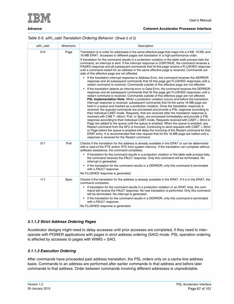
User’s Manual
Advance Coherent Accelerator Processor Interface
Version 1.229 January 2015
PSL Accelerator Interface
Page 67 of 101
5.1.1.2 Strict Address Ordering Pages
Accelerator designs might need to delay accesses until prior accesses are completed, if they need to inter-operate with POWER applications with pages in strict address ordering (SAO) mode. PSL operation ordering is affected by accesses to pages with WIMG = SAO.
5.1.1.3 Execution Ordering
After commands have proceeded past address translation, the PSL orders only on a cache-line address basis. Commands to an address are performed after earlier commands to that address and before later commands to that address. Order between commands involving different addresses is unpredictable.
010 Page Translation is in order for addresses in the same effective page that maps into a 4 KB, 16 KB, and 16 MB ERAT. Accesses to different pages exit translation in a high-performance order.If translation for the command results in a protection violation or the table walk process fails the command, an interrupt is sent. If the interrupt response is CONTINUE, the command receives a PAGED response and all subsequent commands that hit this page receive a FLUSHED response until a command restart for an address in the same effective page is received. Commands out-side of this effective page are not affected.
• If the translation interrupt response is Address Error, the command receives the AERROR response and all subsequent commands that hit this page get FLUSHED responses until a restart command is received. Commands outside of this effective page are not affected.
• If the translation detects an internal error or Data Error, the command receives the DERROR response and all subsequent commands that hit this page get FLUSHED responses until a restart command is received. Commands outside of this effective page are not affected.PSL Implementation Note: When a protection violation occurs and before the translation interrupt response is received, subsequent commands that hit the same 16 MB page are held in a queue and marked as a protection violation. Once the translation response is received, the queued commands are processed and provide a PSL response according to their individual CABT mode. Requests, that are received after the translation response is received with CAB T =Abort, Pref, or Spec, are processed immediately and provide a PSL response according to their individual CABT mode. Requests received with CABT = Strict or Page are added to the queue until the queue is emptied. When the queue is emptied, any Restart command from the AFU is honored. Continuing to send requests with CABT = Strict or Page before the queue is emptied will delay the honoring of the Restart command for that ERAT entry. It is recommended that new request that hit the 16 MB page are halted until a response is received for the Restart command.
011 Pref Checks if the translation for the address is already available in the ERAT or can be determined with a read of the PTE and/or STE from system memory. If the translation can complete without software assistance, the command completes.
• If translation for the command results in a protection violation or the table walk process fails, the command receives the FAULT response. Only this command will be terminated. No interrupt is generated.
• If the translation for the command results in a DERROR, only this command is terminated with a FAULT response.
No FLUSHED response is generated.
111 Spec Checks if the translation for the address is already available in the ERAT. If it is in the ERAT, the command completes.
• If translation for the command results in a protection violation or an ERAT miss, the com-mand will receive the FAULT response. No new translation is performed. Only this command will be terminated. No interrupt is generated.
• If the translation for the command results in a DERROR, only this command is terminated with a FAULT response.
No FLUSHED response is generated
Table 5-5. aXh_cabt Translation Ordering Behavior (Sheet 2 of 2)
aXh_cabt Mnemonic Description
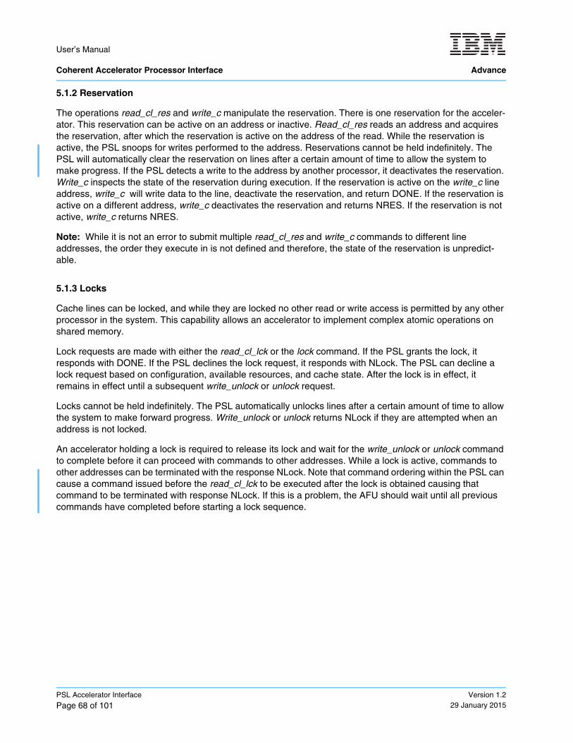
User’s Manual Coherent Accelerator Processor Interface Advance
PSL Accelerator Interface
Page 68 of 101Version 1.2
29 January 2015
5.1.2 Reservation
The operations read_cl_res and write_c manipulate the reservation. There is one reservation for the acceler-ator. This reservation can be active on an address or inactive. Read_cl_res reads an address and acquires the reservation, after which the reservation is active on the address of the read. While the reservation is active, the PSL snoops for writes performed to the address. Reservations cannot be held indefinitely. The PSL will automatically clear the reservation on lines after a certain amount of time to allow the system to make progress. If the PSL detects a write to the address by another processor, it deactivates the reservation. Write_c inspects the state of the reservation during execution. If the reservation is active on the write_c line address, write_c will write data to the line, deactivate the reservation, and return DONE. If the reservation is active on a different address, write_c deactivates the reservation and returns NRES. If the reservation is not active, write_c returns NRES.
Note: While it is not an error to submit multiple read_cl_res and write_c commands to different line addresses, the order they execute in is not defined and therefore, the state of the reservation is unpredict-able.
5.1.3 Locks
Cache lines can be locked, and while they are locked no other read or write access is permitted by any other processor in the system. This capability allows an accelerator to implement complex atomic operations on shared memory.
Lock requests are made with either the read_cl_lck or the lock command. If the PSL grants the lock, it responds with DONE. If the PSL declines the lock request, it responds with NLock. The PSL can decline a lock request based on configuration, available resources, and cache state. After the lock is in effect, it remains in effect until a subsequent write_unlock or unlock request.
Locks cannot be held indefinitely. The PSL automatically unlocks lines after a certain amount of time to allow the system to make forward progress. Write_unlock or unlock returns NLock if they are attempted when an address is not locked.
An accelerator holding a lock is required to release its lock and wait for the write_unlock or unlock command to complete before it can proceed with commands to other addresses. While a lock is active, commands to other addresses can be terminated with the response NLock. Note that command ordering within the PSL can cause a command issued before the read_cl_lck to be executed after the lock is obtained causing that command to be terminated with response NLock. If this is a problem, the AFU should wait until all previous commands have completed before starting a lock sequence.
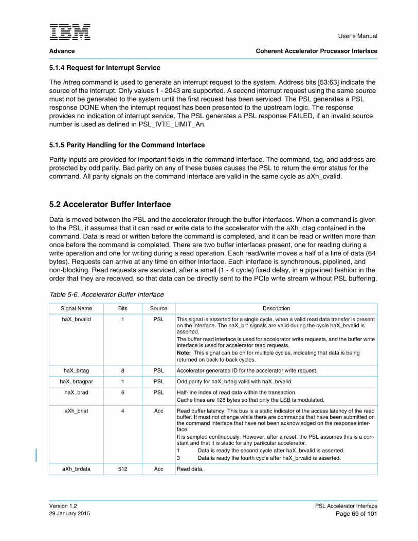
User’s Manual
Advance Coherent Accelerator Processor Interface
Version 1.229 January 2015
PSL Accelerator Interface
Page 69 of 101
5.1.4 Request for Interrupt Service
The intreq command is used to generate an interrupt request to the system. Address bits [53:63] indicate the source of the interrupt. Only values 1 - 2043 are supported. A second interrupt request using the same source must not be generated to the system until the first request has been serviced. The PSL generates a PSL response DONE when the interrupt request has been presented to the upstream logic. The response provides no indication of interrupt service. The PSL generates a PSL response FAILED, if an invalid source number is used as defined in PSL_IVTE_LIMIT_An.
5.1.5 Parity Handling for the Command Interface
Parity inputs are provided for important fields in the command interface. The command, tag, and address are protected by odd parity. Bad parity on any of these buses causes the PSL to return the error status for the command. All parity signals on the command interface are valid in the same cycle as aXh_cvalid.
5.2 Accelerator Buffer Interface
Data is moved between the PSL and the accelerator through the buffer interfaces. When a command is given to the PSL, it assumes that it can read or write data to the accelerator with the aXh_ctag contained in the command. Data is read or written before the command is completed, and it can be read or written more than once before the command is completed. There are two buffer interfaces present, one for reading during a write operation and one for writing during a read operation. Each read/write moves a half of a line of data (64 bytes). Requests can arrive at any time on either interface. Each interface is synchronous, pipelined, and non-blocking. Read requests are serviced, after a small (1 - 4 cycle) fixed delay, in a pipelined fashion in the order that they are received, so that data can be directly sent to the PCIe write stream without PSL buffering.
Table 5-6. Accelerator Buffer Interface
Signal Name Bits Source Description
haX_brvalid 1 PSL This signal is asserted for a single cycle, when a valid read data transfer is present on the interface. The haX_br* signals are valid during the cycle haX_brvalid is asserted. The buffer read interface is used for accelerator write requests, and the buffer write interface is used for accelerator read requests.Note: This signal can be on for multiple cycles, indicating that data is being returned on back-to-back cycles.
haX_brtag 8 PSL Accelerator generated ID for the accelerator write request.
haX_brtagpar 1 PSL Odd parity for haX_brtag valid with haX_brvalid.
haX_brad 6 PSL Half-line index of read data within the transaction.Cache lines are 128 bytes so that only the LSB is modulated.
aXh_brlat 4 Acc Read buffer latency. This bus is a static indicator of the access latency of the read buffer. It must not change while there are commands that have been submitted on the command interface that have not been acknowledged on the response inter-face.It is sampled continuously. However, after a reset, the PSL assumes this is a con-stant and that it is static for any particular accelerator.1 Data is ready the second cycle after haX_brvalid is asserted.3 Data is ready the fourth cycle after haX_brvalid is asserted.
aXh_brdata 512 Acc Read data.
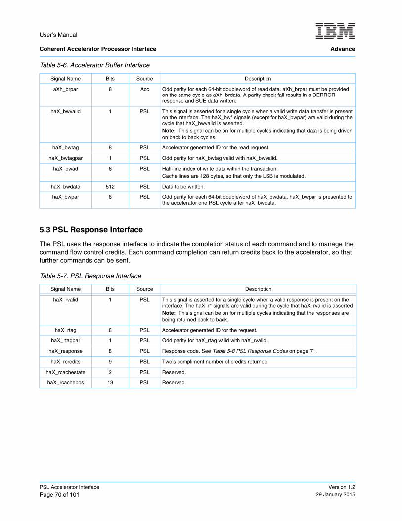
User’s Manual Coherent Accelerator Processor Interface Advance
PSL Accelerator Interface
Page 70 of 101Version 1.2
29 January 2015
5.3 PSL Response Interface
The PSL uses the response interface to indicate the completion status of each command and to manage the command flow control credits. Each command completion can return credits back to the accelerator, so that further commands can be sent.
aXh_brpar 8 Acc Odd parity for each 64-bit doubleword of read data. aXh_brpar must be provided on the same cycle as aXh_brdata. A parity check fail results in a DERROR response and SUE data written.
haX_bwvalid 1 PSL This signal is asserted for a single cycle when a valid write data transfer is present on the interface. The haX_bw* signals (except for haX_bwpar) are valid during the cycle that haX_bwvalid is asserted.Note: This signal can be on for multiple cycles indicating that data is being driven on back to back cycles.
haX_bwtag 8 PSL Accelerator generated ID for the read request.
haX_bwtagpar 1 PSL Odd parity for haX_bwtag valid with haX_bwvalid.
haX_bwad 6 PSL Half-line index of write data within the transaction.Cache lines are 128 bytes, so that only the LSB is modulated.
haX_bwdata 512 PSL Data to be written.
haX_bwpar 8 PSL Odd parity for each 64-bit doubleword of haX_bwdata. haX_bwpar is presented to the accelerator one PSL cycle after haX_bwdata.
Table 5-7. PSL Response Interface
Signal Name Bits Source Description
haX_rvalid 1 PSL This signal is asserted for a single cycle when a valid response is present on the interface. The haX_r* signals are valid during the cycle that haX_rvalid is assertedNote: This signal can be on for multiple cycles indicating that the responses are being returned back to back.
haX_rtag 8 PSL Accelerator generated ID for the request.
haX_rtagpar 1 PSL Odd parity for haX_rtag valid with haX_rvalid.
haX_response 8 PSL Response code. See Table 5-8 PSL Response Codes on page 71.
haX_rcredits 9 PSL Two’s compliment number of credits returned.
haX_rcachestate 2 PSL Reserved.
haX_rcachepos 13 PSL Reserved.
Table 5-6. Accelerator Buffer Interface
Signal Name Bits Source Description
special uncorrectable error
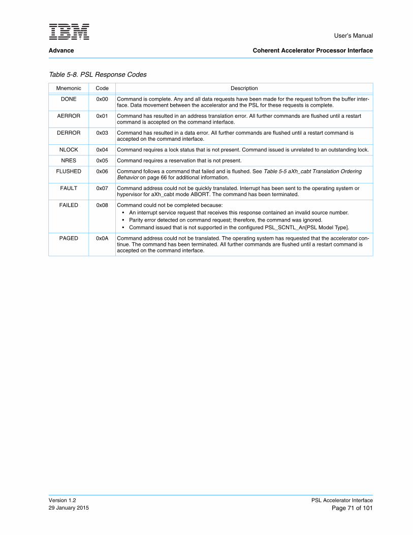
User’s Manual
Advance Coherent Accelerator Processor Interface
Version 1.229 January 2015
PSL Accelerator Interface
Page 71 of 101
Table 5-8. PSL Response Codes
Mnemonic Code Description
DONE 0x00 Command is complete. Any and all data requests have been made for the request to/from the buffer inter-face. Data movement between the accelerator and the PSL for these requests is complete.
AERROR 0x01 Command has resulted in an address translation error. All further commands are flushed until a restart command is accepted on the command interface.
DERROR 0x03 Command has resulted in a data error. All further commands are flushed until a restart command is accepted on the command interface.
NLOCK 0x04 Command requires a lock status that is not present. Command issued is unrelated to an outstanding lock.
NRES 0x05 Command requires a reservation that is not present.
FLUSHED 0x06 Command follows a command that failed and is flushed. See Table 5-5 aXh_cabt Translation Ordering Behavior on page 66 for additional information.
FAULT 0x07 Command address could not be quickly translated. Interrupt has been sent to the operating system or hypervisor for aXh_cabt mode ABORT. The command has been terminated.
FAILED 0x08 Command could not be completed because:• An interrupt service request that receives this response contained an invalid source number.• Parity error detected on command request; therefore, the command was ignored.• Command issued that is not supported in the configured PSL_SCNTL_An[PSL Model Type].
PAGED 0x0A Command address could not be translated. The operating system has requested that the accelerator con-tinue. The command has been terminated. All further commands are flushed until a restart command is accepted on the command interface.
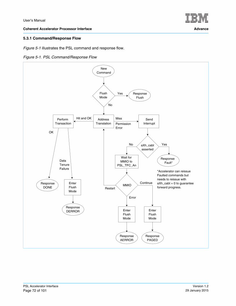
User’s Manual Coherent Accelerator Processor Interface Advance
PSL Accelerator Interface
Page 72 of 101Version 1.2
29 January 2015
5.3.1 Command/Response Flow
Figure 5-1 illustrates the PSL command and response flow.
Figure 5-1. PSL Command/Response Flow
NewCommand
Address Miss
aXh_cabtasserted
Response
Yes
Fault*
No
SendInterrupt
Wait for MMIO to
MMIORestart
Error
ResponseAERROR
EnterFlushMode
FlushMode
Yes
No
ResponseFlush
Perform Transaction
ResponseDONE
ResponseDERROR
DataTenureFailure
OK
Translation
Hit and OK
*Accelerator can reissueFaulted commands butneeds to reissue withaXh_cabt = 0 to guaranteeforward progress.
EnterFlushMode
Permission
Continue
ResponsePAGED
EnterFlushMode
Error
PSL_TFC_An
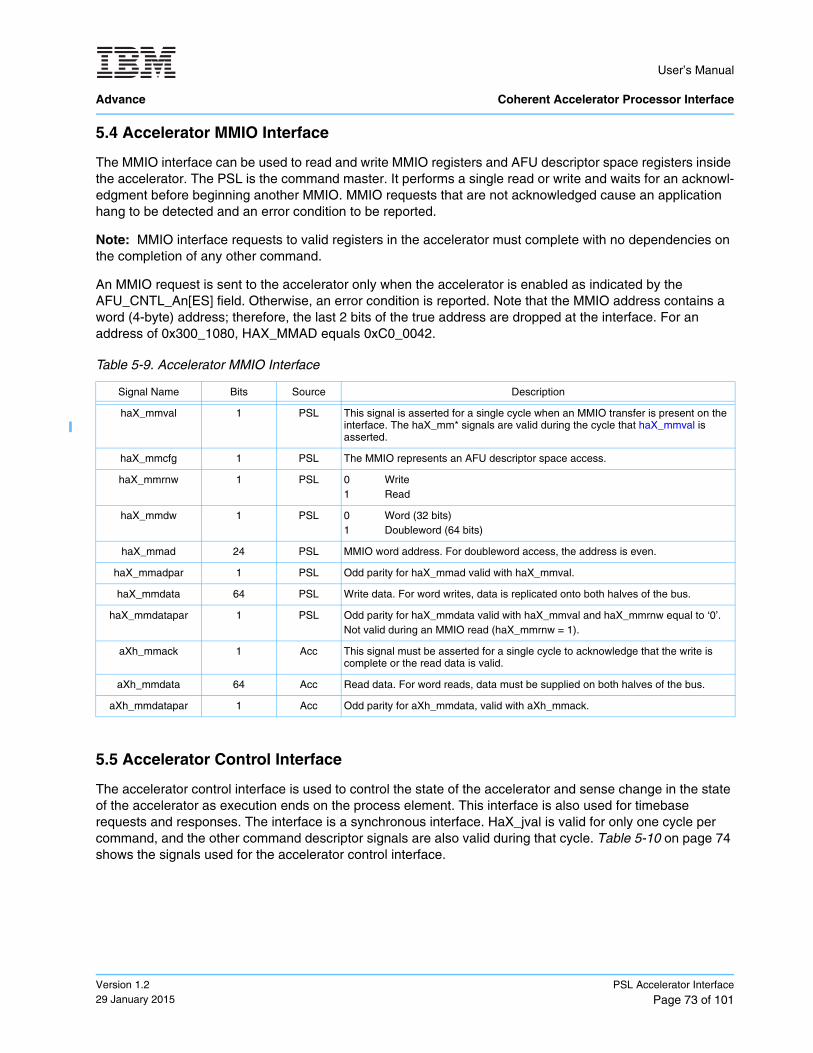
User’s Manual
Advance Coherent Accelerator Processor Interface
Version 1.229 January 2015
PSL Accelerator Interface
Page 73 of 101
5.4 Accelerator MMIO Interface
The MMIO interface can be used to read and write MMIO registers and AFU descriptor space registers inside the accelerator. The PSL is the command master. It performs a single read or write and waits for an acknowl-edgment before beginning another MMIO. MMIO requests that are not acknowledged cause an application hang to be detected and an error condition to be reported.
Note: MMIO interface requests to valid registers in the accelerator must complete with no dependencies on the completion of any other command.
An MMIO request is sent to the accelerator only when the accelerator is enabled as indicated by the AFU_CNTL_An[ES] field. Otherwise, an error condition is reported. Note that the MMIO address contains a word (4-byte) address; therefore, the last 2 bits of the true address are dropped at the interface. For an address of 0x300_1080, HAX_MMAD equals 0xC0_0042.
5.5 Accelerator Control Interface
The accelerator control interface is used to control the state of the accelerator and sense change in the state of the accelerator as execution ends on the process element. This interface is also used for timebase requests and responses. The interface is a synchronous interface. HaX_jval is valid for only one cycle per command, and the other command descriptor signals are also valid during that cycle. Table 5-10 on page 74 shows the signals used for the accelerator control interface.
Table 5-9. Accelerator MMIO Interface
Signal Name Bits Source Description
haX_mmval 1 PSL This signal is asserted for a single cycle when an MMIO transfer is present on the interface. The haX_mm* signals are valid during the cycle that haX_mmval is asserted.
haX_mmcfg 1 PSL The MMIO represents an AFU descriptor space access.
haX_mmrnw 1 PSL 0 Write1 Read
haX_mmdw 1 PSL 0 Word (32 bits)1 Doubleword (64 bits)
haX_mmad 24 PSL MMIO word address. For doubleword access, the address is even.
haX_mmadpar 1 PSL Odd parity for haX_mmad valid with haX_mmval.
haX_mmdata 64 PSL Write data. For word writes, data is replicated onto both halves of the bus.
haX_mmdatapar 1 PSL Odd parity for haX_mmdata valid with haX_mmval and haX_mmrnw equal to ‘0’. Not valid during an MMIO read (haX_mmrnw = 1).
aXh_mmack 1 Acc This signal must be asserted for a single cycle to acknowledge that the write is complete or the read data is valid.
aXh_mmdata 64 Acc Read data. For word reads, data must be supplied on both halves of the bus.
aXh_mmdatapar 1 Acc Odd parity for aXh_mmdata, valid with aXh_mmack.
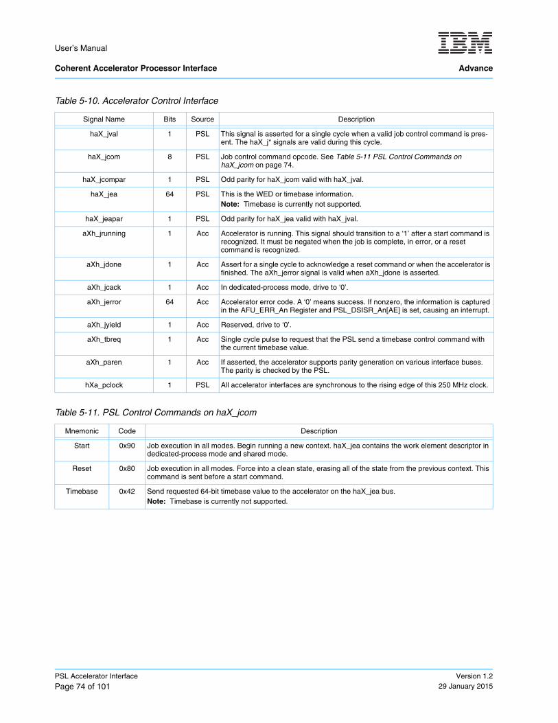
User’s Manual Coherent Accelerator Processor Interface Advance
PSL Accelerator Interface
Page 74 of 101Version 1.2
29 January 2015
Table 5-10. Accelerator Control Interface
Signal Name Bits Source Description
haX_jval 1 PSL This signal is asserted for a single cycle when a valid job control command is pres-ent. The haX_j* signals are valid during this cycle.
haX_jcom 8 PSL Job control command opcode. See Table 5-11 PSL Control Commands on haX_jcom on page 74.
haX_jcompar 1 PSL Odd parity for haX_jcom valid with haX_jval.
haX_jea 64 PSL This is the WED or timebase information.Note: Timebase is currently not supported.
haX_jeapar 1 PSL Odd parity for haX_jea valid with haX_jval.
aXh_jrunning 1 Acc Accelerator is running. This signal should transition to a ‘1’ after a start command is recognized. It must be negated when the job is complete, in error, or a reset command is recognized.
aXh_jdone 1 Acc Assert for a single cycle to acknowledge a reset command or when the accelerator is finished. The aXh_jerror signal is valid when aXh_jdone is asserted.
aXh_jcack 1 Acc In dedicated-process mode, drive to ‘0’.
aXh_jerror 64 Acc Accelerator error code. A ‘0’ means success. If nonzero, the information is captured in the AFU_ERR_An Register and PSL_DSISR_An[AE] is set, causing an interrupt.
aXh_jyield 1 Acc Reserved, drive to ‘0’.
aXh_tbreq 1 Acc Single cycle pulse to request that the PSL send a timebase control command with the current timebase value.
aXh_paren 1 Acc If asserted, the accelerator supports parity generation on various interface buses. The parity is checked by the PSL.
hXa_pclock 1 PSL All accelerator interfaces are synchronous to the rising edge of this 250 MHz clock.
Table 5-11. PSL Control Commands on haX_jcom
Mnemonic Code Description
Start 0x90 Job execution in all modes. Begin running a new context. haX_jea contains the work element descriptor in dedicated-process mode and shared mode.
Reset 0x80 Job execution in all modes. Force into a clean state, erasing all of the state from the previous context. This command is sent before a start command.
Timebase 0x42 Send requested 64-bit timebase value to the accelerator on the haX_jea bus.Note: Timebase is currently not supported.
User’s Manual
Advance Coherent Accelerator Processor Interface
Version 1.229 January 2015
PSL Accelerator Interface
Page 75 of 101
5.5.1 Accelerator Control Interface in the Non-Shared Mode
In a non-shared mode, the hypervisor must always reset and enable the AFU through the AFU_CNTL_A Register as shown in Figure 5-2 PSL Accelerator Control Interface Flow in Non-Shared Mode on page 76. While the accelerator is enabled, the following functions are possible:
• Requests can be submitted to the PSL through the command interface.
• MMIO requests can be passed from the PSL to the accelerator and must be acknowledged.
• Timebase values can be passed to the accelerator.
When a PSL slice is initialized for dedicated-process mode, the PSL fetches the process element from system memory if the address specified in PSL_SPAP_An is valid when the AFU_CNTL_A [Enable] is set to ‘1’. If the PSl_SPAP_An address is not valid, the PSL assumes that the process element registers have been initialized by software already, so the start command is immediately sent to the AFU. The 64-bit hax_jea indi-cates the value of the work element descriptor.
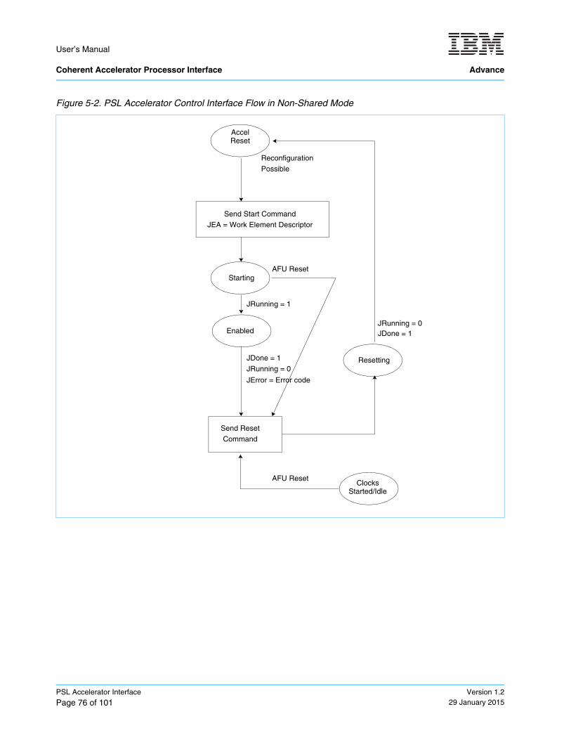
User’s Manual Coherent Accelerator Processor Interface Advance
PSL Accelerator Interface
Page 76 of 101Version 1.2
29 January 2015
Figure 5-2. PSL Accelerator Control Interface Flow in Non-Shared Mode
JDone = 1
Send Start CommandJEA = Work Element Descriptor
Starting
Enabled
JRunning = 0
JError = Error code
JRunning = 1
Send Reset
Resetting
JDone = 1
Reconfiguration
Possible
JRunning = 0
Command
Accel Reset
Clocks Started/Idle
AFU Reset
AFU Reset
User’s Manual
Advance Coherent Accelerator Processor Interface
Version 1.229 January 2015
PSL Accelerator Interface
Page 77 of 101
5.5.2 Accelerator Control Interface for Timebase
Note: Timebase is currently not supported.
The accelerator requests the latest timebase information by asserting aXh_tbreq on the accelerator control interface for one cycle. Only one request can be issued at a time. The PSL returns the timebase information by asserting haX_jval = ‘1’, haX_jcom = timebase, and haX_jea = timebase value (0:63).

User’s Manual Coherent Accelerator Processor Interface Advance
PSL Accelerator Interface
Page 78 of 101Version 1.2
29 January 2015
User’s Manual
Advance Coherent Accelerator Processor Interface
Version 1.229 January 2015
CAPI Low-Level Management (libcxl)
Page 79 of 101
6. CAPI Low-Level Management (libcxl)
6.1 Overview
Note: The CAPI Developer Kit release does not support partial reconfiguration.
The CAPI accelerator management library (libcxl) is a low-level management library that consists of the following categories of POWER functions.
• Adapter Information and Availability on page 80
• Accelerated Function Unit Selection on page 81
• Accelerated Function Unit Management on page 82
Libcxl introduces the following terms:
Note: The CAPI Accelerator Management Library is still under development. Currently, libcxl only supports the dedicated programming model.
The following sections describe the contents of libcxl. In the Developer Kit release, a number of these calls are not implemented. They will be implemented in the future as the architecture expands beyond the contents of the CAPI Developer Kit release. CAPI Developer Kit users should focus on the following routines to start and eventually close their AFU.
Accelerator The physical accelerator available to the system. A task is sent to a hardware thread within the physical accelerator.
Hardware Thread The physical accelerator function unit within a physical accelerator.
Accelerator Instance An accelerator with a defined function. The function can either be defined by the system or by the application depending on if the accelerator is shared or dedi-cated.
Dedicated Accelerators An accelerator that is dedicated to a single process in the system. These types of accelerators are operating in the dedicated-process virtualization program-ming model defined by the Coherent Accelerator Interface Architecture (CAIA).
Virtualized Accelerators An accelerator that is shared between one or more processes in the system. These types of accelerators are operating in either the shared or dedicated-partition virtualization programming models defined by the Coherent Accelerator Interface Architecture (CAIA).
cxl_afu_open_dev Opens an existing AFU by its device path name and returns a handle to the open device. It is necessary for the user to know the device name that has been asso-ciated with their AFU.
cxl_afu_attach Passes the work element descriptor (WED) to the FPGA and enables the given AFU for operation.
cxl_mmio_map Maps the register space in the AFU into the memory associated with this process. See Section 6.2.3.14 Additional Routines on page 84 and Section 6.2.3.13 cxl_mmio_write on page 84 for details about how to read and write registers in this space.
Coherent Accelerator Process Interface
Field-programmable gate array
User’s Manual Coherent Accelerator Processor Interface Advance
CAPI Low-Level Management (libcxl)
Page 80 of 101Version 1.2
29 January 2015
6.2 CAPI Low-Level Management API
6.2.1 Adapter Information and Availability
This section describes API calls used by an application to determine what resources are available and to query information about resources allocated to the calling process.
6.2.1.1 cxl_adapter_next
Note: Not applicable for the CAPI Developer Kit.
#include <libcxl.h>struct cxl_adapter_h * cxl_adapter_next(struct cxl_adapter_h *adapter);
The cxl_adapter_next returns a handle to the next available CAPI capable adapter. If the input adapter pointer is NULL, this routine will allocate the necessary buffer and return its pointer. A subsequent call to this routine obtains the directory entry of the next adapter. If there are no more adapters, the buffers are freed and the routine returns NULL.
6.2.1.2 cxl_adapter_devname
Note: Not applicable for the CAPI Developer Kit.
#include <libcxl.h>char * cxl_adapter_devname(struct cxl_adapter_h *adapter);
The cxl_adapter_devname returns the null terminated string that represents the device path name of the CAPI capable adapter.
6.2.1.3 cxl_adapter_free
Note: Not applicable for the CAPI Developer Kit.
#include <libcxl.h>void cxl_adapter_free(struct cxl_adapter_h *adapter);
The cxl_adapter_free routine frees the buffers associated the adapter handle.
cxl_mmio_unmap Unmaps the register space of the AFU from the memory associated with this process.
cxl_afu_free Closes and frees the AFU and the related supporting data structures that have been allocated.
User’s Manual
Advance Coherent Accelerator Processor Interface
Version 1.229 January 2015
CAPI Low-Level Management (libcxl)
Page 81 of 101
6.2.1.4 cxl_for_each_adapter
Note: Not applicable for the CAPI Developer Kit.
#include <libcxl.h>#define cxl_for_each_adapter(adapter) \ for (adapter = cxl_adapter_next(NULL); \ adapter; \ adapter = cxl_adapter_next(adapter))
This macro visits each CAPI capable adapter in the system.
6.2.2 Accelerated Function Unit Selection
6.2.2.1 cxl_adapter_afu_next
Note: Not applicable for the CAPI Developer Kit.
#include <libcxl.h>struct cxl_afu_h * cxl_adapter_afu_next(struct cxl_adapter_h *adapter, struct cxl_afu_h *afu);
The cxl_adapter_afu_next routine returns a handle to the next available AFU on a given CAPI capable adapter. The adapter parameter must not be NULL. If the AFU parameter is NULL, cxl_adapter_afu_next returns a pointer to the buffer holding the information for the first available AFU on this adapter. Subsequent calls to this routine return the information for the next AFU on this adapter. If there are no more remaining AFUs, the buffer for the AFU information is freed and NULL is returned.
6.2.2.2 cxl_afu_next
Note: Not applicable for the CAPI Developer Kit.
#include <libcxl.h>struct cxl_afu_h * cxl_afu_next(struct cxl_afu_h *afu);
The cxl_afu_next routine returns a handle to the next available AFU on the next CAPI capable adapter. If the AFU parameter is NULL, the routine allocates buffers for the CXL adapter information and AFU information and returns the pointer to the AFU information buffer that contains the information for the first available adapter and AFU. Subsequent calls iterate first through the AFU on the current adapter (stored in the AFU buffer). The routine advances to next adapter after exhausting all the AFUs on the current adapter and returns the information for the first AFU on that adapter.
6.2.2.3 cxl_afu_devname
Note: Not applicable for the CAPI Developer Kit.
#include <libcxl.h>char * cxl_afu_devname(struct cxl_afu_h *afu);
The cxl_afu_devname routine returns the path name that represents the AFU associated with the given AFU handle.
User’s Manual Coherent Accelerator Processor Interface Advance
CAPI Low-Level Management (libcxl)
Page 82 of 101Version 1.2
29 January 2015
6.2.2.4 cxl_for_each_adapter_afu
Note: Not applicable for the CAPI Developer Kit.
#include <libcxl.h>#define cxl_for_each_adapter_afu(adapter, afu) \ for (afu = cxl_adapter_afu_next(adapter, NULL); \ afu; \ afu = cxl_adapter_afu_next(NULL, afu))
The cxl_for_each_adapter_afu macro sets up a loop to iterate through each AFU on a given adapter.
6.2.2.5 cxl_for_each_afu
Note: Not applicable for the CAPI Developer Kit.
#include <libcxl.h>#define cxl_for_each_afu(afu) \ for (afu = cxl_afu_next(NULL); afu; afu = cxl_afu_next(afu))
The cxl_for_each_afu macro sets up a loop to iterate through each AFU in the system by also looping through the cxl adapters in the system.
6.2.3 Accelerated Function Unit Management
6.2.3.1 cxl_afu_open_dev
#include <libcxl.h>struct cxl_afu_h * cxl_afu_open_dev(char *path);
The cxl_afu_open_dev routine opens an existing AFU by its device path name. It returns a handle to the open device. In the CAPI Developer Kit release, this returns a negative number if the AFU is unavailable for some reason. In the CAPI Developer Kit release, the programmer will probably know the full device name of their AFU.
6.2.3.2 cxl_afu_open_h
Note: Not applicable for the CAPI Developer Kit.
#include <libcxl.h>int cxl_afu_open_h(struct cxl_afu_h *afu, unsigned long master);
6.2.3.3 cxl_afu_fd_to_h
Note: Not applicable for the CAPI Developer Kit.
#include <libcxl.h>struct cxl_afu_h * cxl_afu_fd_to_h(int fd);
The cxl_afu_fd_to_h routine inserts the file descriptor parameter in a newly allocated AFU buffer. The routine returns the pointer to the allocated AFU buffer.
User’s Manual
Advance Coherent Accelerator Processor Interface
Version 1.229 January 2015
CAPI Low-Level Management (libcxl)
Page 83 of 101
6.2.3.4 cxl_afu_free
#include <libcxl.h>void cxl_afu_free(struct cxl_afu_h *afu);
The routine cxl_afu_free releases the buffers allocated to hold the handle, file descriptor, and other informa-tion require by the device. It also closes the device, thereby releasing it from the process so that a subse-quent process can open the device.
6.2.3.5 cxl_afu_attach
#include <libcxl.h>int cxl_afu_attach(struct cxl_afu_h *afu, _uint64_t wed);
The routine cxl_afu_attach creates the connection between the current process and the AFU on the acceler-ator card. The calling process will have established an accelerator specified work element descriptor (WED). This routine resets the AFU, transmits the WED to the AFU, and enables the AFU.
6.2.3.6 cxl_afu_attach_full
Note: Not applicable for the CAPI Developer Kit.
#include <libcxl.h>int cxl_afu_attach_full(struct cxl_afu_h *afu,
_uint64_t wed, __u16 num_interrupts,__u16 *process_element);
The routine cxl_afu_attach_full creates the connection between the current process and the AFU on the accelerator card. The calling process will have established an accelerator specified work element descriptor (WED). The calling process can specify a number of interrupts that it can process or it can rely on the number of interrupts that are defined by the accelerator in the AFU descriptor (num_interrupts = ‘-1’). The routine can also return the process element number if the process element pointer is nonzero. This routine resets the AFU, transmits the WED to the AFU, and enables the AFU.
6.2.3.7 cxl_afu_fd
Note: Not applicable for the CAPI Developer Kit.
#include <libcxl.h>int cxl_afu_fd(struct cxl_afu_h *afu);
The cxl_afu_fd routine returns the file descriptor of the AFU that is contained in the AFU handle.
6.2.3.8 cxl_afu_open_and_attach
Note: Not applicable for the CAPI Developer Kit.
#include <libcxl.h>int cxl_afu_open_and_attach(struct cxl_afu_h *afu, mode);
User’s Manual Coherent Accelerator Processor Interface Advance
CAPI Low-Level Management (libcxl)
Page 84 of 101Version 1.2
29 January 2015
6.2.3.9 cxl_afu_sysfs_pci
Note: Not applicable for the CAPI Developer Kit.
#include <libcxl.h>int cxl_afu_sysfs_pci(char **pathp, struct cxl_afu_h *afu)
6.2.3.10 cxl_mmio_map
#include <libcxl.h>int cxl_mmio_map(struct cxl_afu_h *afu, u32 flags)
This routine returns the base virtual address of the register space of the AFU indicated by the AFU parameter and adds that space to the calling processes’ virtual address space. The flag parameter indicates the key characteristics of the register space. One such characteristic is endianess.
6.2.3.11 cxl_mmio_unmap
#include <libcxl.h>int cxl_mmio_unmap(struct cxl_afu_h *afu, _uint32_t *data)
This routine removes the indicated AFU’s register space from the calling processes’ virtual address space.
6.2.3.12 cxl_mmio_read
#include <libcxl.h>_uint64_t cxl_afu_mmio_read64(struct cxl_afu_h *afu, _uint64_t offset)_uint32_t cxl_afu_mmio_read32(struct cxl_afu_h *afu, _uint64_t offset)
These two routines are read from a (32- or 64-bit) register in the indicated AFU. The offset parameter indi-cates the register to be read. Data is returned to the local address space. The data parameter is a pointer to the location in memory at which the data from the AFU should be placed.
6.2.3.13 cxl_mmio_write
#include <libcxl.h>void cxl_afu_mmio_write64(struct cxl_afu_h *afu, __uint64_t offset, _uint64_t data)void cxl_afu_mmio_write32(struct cxl_afu_h *afu, _uint64_t offset, _uint32_t data)
These two routines write to a (32- or 64-bit) register in the indicated AFU’s register space. The data (32 or 64 bits long) indicated by the data parameter is written to the register in the AFU indicated by the offset param-eter.
6.2.3.14 Additional Routines
The following accelerated function unit management routines are also available:
• cxl_read_event• cxl_read_expected_event• fprint_cxl_event• fprint_cxl_unknown_event
User’s Manual
Advance Coherent Accelerator Processor Interface
Version 1.229 January 2015
CAPI Low-Level Management (libcxl)
Page 85 of 101
User’s Manual Coherent Accelerator Processor Interface Advance
CAPI Low-Level Management (libcxl)
Page 86 of 101Version 1.2
29 January 2015
User’s Manual
Advance Coherent Accelerator Processor Interface
Version 1.229 January 2015
AFU Development and Design
Page 87 of 101
7. AFU Development and Design
The previous sections describe the overall CAIA architecture, the PSL interfaces, and application library calls. This section describes some general information about developing an accelerator functional unit (AFU).
7.1 High-Level Planning
Before starting development work on an AFU, the user should become familiar with CAPI, which includes reading this document and any other education material, as well as determining the hardware implementation that the AFU will reside on. Implementation-dependent information for this version of the document begins in Section 8 CAPI Developer Kit Card on page 93. The user must ensure that they have access to any needed FPGA development tools and hardware that is specific to each implementation. A rough sizing must also be done at this point to ensure that the AFU will fit on the available space within the FPGA for a given implemen-tation. Planning for the needed hardware systems must also begin in this early stage.
7.2 Development
The following sections describe some topics and examples that should be considered during the develop-ment stage.
7.2.1 Design Language
Determine what design language will be used to develop the AFU. This language must be a type that is compatible with the FPGA toolset and compilable for a simulation environment.
7.2.2 High-Level Design of the AFU
Consider AFU partitions, interfaces to the PSL, command, and dataflow logic. Estimate latch and RAM cell requirements for size estimates of the logic. Begin early floorplan work with the FPGA footprint. Import the post-routed PSL into the project along with the example memcpy AFU to get an initial look at what the PSL will occupy in the floorplan. Consider how debug of the logic will be performed. One possible debug aid is to route information to FPGA memories as trace arrays that can be read after a fail to determine the command sequence that caused a fail. One might also capture failure information into registers, so that more informa-tion can be accessed after an error occurs. A high-level performance target should also be established before implementation begins.
Examples of some FPGA considerations during the high-level design that can impact both performance and floorplanning are:
• RAM cells must be used whenever possible, because they are much more area efficient than latches.
• Wiring delays are large and consume FPGA area. Avoid routing a large number of wires to many destina-tions whenever possible.
• The PSL supplies a 250 MHz clock for the AFU implementation and no DLL or PLL is required unless there is a unique clocking requirement.
• Consider the number of logic levels between latch stages and pipeline the design. Be aware of this with performance targets.
Coherent Accelerator Interface Architecture
POWER service layer
Coherent Accelerator Process Interface
Field-programmable gate array
resource allocation management
Delay locked loop
Phase locked loop
User’s Manual Coherent Accelerator Processor Interface Advance
AFU Development and Design
Page 88 of 101Version 1.2
29 January 2015
• Use FPGA floorplanning for AFU internal logic blocks to help the FPGA tools place the logic optimally and have repeatable synthesis and timing results.
7.2.2.1 Floorplan Considerations
The PSL uses just under 25% of the Stratix V FPGA’s ALUTs, arrays, and DSPs. For estimation purposes, plan on your algorithm fitting in 70% of the overall ALUTs, arrays, and DSPs. The maximum remaining resources after placing the PSL is shown in Table 7-1.
7.2.3 Application Development
Develop host application code that makes use of libcxl to call the AFU. See Section 6 CAPI Low-Level Management (libcxl) on page 79 for additional information.
7.2.4 AFU Development
Code the AFU in the chosen design language. Perform unit simulations to verify that the internal accelerator function is operating correctly. Some simulation with a basic PSL interface driver (customer developed) can be done in this unit simulation stage. Synthesize with the FPGA tools in the implementation environment to ensure that timing is met. Make floorplan and logic updates as needed for timing closure and bug fixes.
7.2.5 Develop Lab Test Plan for the AFU
Develop a test plan to determine what testing is needed to validate the hardware and application function after hardware testing begins. These tests must also be run in the system simulation environment.
7.2.6 System Simulation of Application and AFU
The POWER8 Functional Simulator provides a system simulation of an entire POWER8 CAPI system by providing the complete system behavior at the AFU-PSL interface. This simulator can be run on a customer platform before actual lab testing with a POWER8 system begins. This simulation ensures compatibility with the PSL interface and verifies the interaction between the application system running on the host and the AFU. See the Power8 Functional Simulator Demo in the HDK/SDK and the POWER8 Functional Simulator User’s Guide for additional information.
7.2.7 Test
After the application and the AFU have been developed and simulated, the test phase on actual hardware begins. The first step is to prepare the AFU FPGA image so that it can be downloaded to the FPGA. The method used is implementation dependent. After the image is downloaded, the application can be started and the lab test plan can be executed.
Table 7-1. FPGA Resources Available for AFU
Item Total Available for AFU
ALUTs 341548
M20K 1874
DSP 188
adaptive lookup table
digital signal processor
User’s Manual
Advance Coherent Accelerator Processor Interface
Version 1.229 January 2015
AFU Development and Design
Page 89 of 101
7.3 Best Practices for AFU Design
7.3.1 FPGA Considerations
See Section 7.2.2 High-Level Design of the AFU on page 87 for FPGA considerations during the high-level design.
7.3.2 General PSL Information
The PSL contains 32 read machines (one reserved for interrupts) and 32 write machines (three reserved for deadlock prevention). An AFU design must balance the use of read and write commands accordingly.
Note: MMIO interface requests to valid registers in the accelerator must complete with no dependencies on the completion of any other command.
7.3.3 Buffer Interface
It is recommended that the PSL read buffer interface (for AFU write data) is implemented so that BRTAG goes directly to the RAM read address, and the data returned on BRDATA is latched after the RAM access to meet the BRLAT = ‘1’ requirement.
7.3.4 PSL Interface Timing
It is recommended that all AFU signals are driven to the PSL directly from a latch, and all PSL to AFU signals are received directly into a latch unless otherwise noted (as in Section 7.3.3 Buffer Interface).
7.3.5 Designing for Performance
PSL command ordering is performance oriented, meaning that the PSL can reorder commands for perfor-mance. If a particular order is intended by the AFU, it is the AFU’s responsibility to send commands in that order. The AFU can select the translation ordering mode though, which can impact performance. This control is described in Table 5-5 aXh_cabt Translation Ordering Behavior on page 66. It is important to understand this, so that translation is done efficiently according to the requirements of the AFU.
Write operation sizes to the PSL must be in powers of 2, and the address must be aligned to the size. Odd alignment and size write operations must be broken into multiple sizes with the correct alignment.
It is advisable that the AFU buffers commands that go to same cache line. Issue them together as one write or read instead of sending multiple shorter commands. If there is a chance that the data will again be used by the AFU, it is good practice to hold it inside the AFU buffers. This minimizes PSL traffic and frees the PSL interface resources for other commands.
Locking commands must be used to make sure a line is not modified while the AFU is holding data in internal buffers. There are two possibilities for this: lock and reservation. Locks are used typically when updates are needed atomically for shared memory. After the PSL grants a lock, it does not allow anybody else to modify that line. The number of locks allowed at a point in time is dependent on the PSL resources available. The AFU can acquire a reservation for any particular line and do write_c operations later, which are successful only if the reservation is available. If some other processor has taken the reservation, the AFU’s previous reservation is killed. Therefore, in cases where it is probable that a line might not be modified, use a reserva-tion instead of a lock.
Field-programmable gate array
POWER service layer
Accelerator functional unit
random access memory
User’s Manual Coherent Accelerator Processor Interface Advance
AFU Development and Design
Page 90 of 101Version 1.2
29 January 2015
Translation misses can cause delays in the PSL-AFU interface. Therefore, using touch_l* commands to make pages come in early to the PSL translation cache is recommended. Also, it is advisable to use large pages to avoid too many translation requests from the PSL to the chip. Care should be used to avoid cache-line thrashing between the PSL cache and the processor cache structure. An application should avoid cases where the application and the AFU are both modifying the same cache line constantly.
7.3.6 Simulation
Stand-alone AFU simulation in an internal environment must be done in the customer’s choice of simulation application to verify the internal function of the AFU. Simulation can also be done with the POWER8 Func-tional Simulator along with the application to ensure proper functionality with the PSL and POWER8 system and software. See the POWER8 Functional Simulator User’s Guide for additional information.
Although the FPGA might reset to all zeros on power up, it is good practice to perform multi-value simulation initial X-states. This ensures that the AFU resets to a state that clears all previous job states and new jobs run without any issues.
7.3.7 Debug Considerations
The problem state interface must be implemented to provide a debug mechanism. Registers can be used to capture errors or runtime status that can then be read using MMIOs to the AFU. This helps debug the AFU during initial bringup, as well as during failure scenarios.
It is also helpful to include trace arrays that can capture a logic analyzer type of trace of a particular interface or function. These trace arrays store a history of events that can later be read out using MMIO registers to aid in the debug of performance or functional problems. At a minimum, the AFU-PSL interface signals should be implemented in the AFU to debug basic issues. The interface signal should be set to the trace array.
Some potential features of a trace array:
• Trigger mechanism to start or stop storing data
• Pattern match to only store a cycle with a particular pattern
• Time or cycle stamp for the relative time between events
Note: An example trace array in Verilog along with the implementation of that trace array in the memcpy example will be provided.
7.3.8 Operating System Error Handling
7.3.8.1 AFU Errors
If the main application is responding and the AFU is in a state to communicate with the main application, the AFU must signal an error by some user defined means. For example:
• Interrupt • Command Response Status• MMIO• Other
Memory-mapped I/O
User’s Manual
Advance Coherent Accelerator Processor Interface
Version 1.229 January 2015
AFU Development and Design
Page 91 of 101
If the main application is not responding or the AFU is not in a state to communicate with the main application, the AFU must assert ah_jdone with a nonzero ah_jerror. The error is logged by the operating system and provided to the applications as an event.
7.3.8.2 Application Errors
Normal signal faults result in the process on the AFU being terminated. If an application determines that the AFU is not responding, the application should either request an AFU reset, terminate the AFU processes, or reload the AFU. Reset is the least invasive. The others require the application to detach and re-attach to the AFU.
7.3.8.3 Errors Reported by the System Including the PSL
The application must monitor the error event. On these errors, the operating system also logs the error, but the AFU will, at the minimum, be reset. The application must reload the AFU to continue. The severity of the error should determine what happened to the adapter:
• Only the AFU was reset. The application might be able to recover.
• The card was reset (meaning the PSL was reloaded).
User’s Manual Coherent Accelerator Processor Interface Advance
AFU Development and Design
Page 92 of 101Version 1.2
29 January 2015
User’s Manual
Advance Coherent Accelerator Processor Interface
Version 1.229 January 2015
CAPI Developer Kit Card
Page 93 of 101
8. CAPI Developer Kit Card
The previous sections describe the overall CAIA architecture, PSL interface, library calls, and general AFU development steps. This section is intended to aid application developers for a specific card called the CAPI Developer Kit card. This section describes the CAIA architecture features supported in this release for the CAPI Developer Kit card.
8.1 Supported CAIA Features
The PSL-AFU interface described in this section assumes the following restrictions on features. Additional interface signals or command opcodes will be required in the future to support some of the architecture features that are not supported in this release.
• Only the dedicated-process programming model is supported.
• Only one AFU is supported per CAPI Developer Kit card.
• LPC memory is not supported.
• The only supported value for axh_brlat value is ‘1’.
• The maximum size of the AFU problem state area is 64 MB.
• The maximum size of the AFU descriptor space is 4 MB.
• Timebase is not supported.
• The CAPI interface might only be available on a subset of the PCIe slots on a POWER system. For exam-ple, the IBM Power Systems S812L and S822L have CAPI enabled on location code P1-C5, P1-C7, P1-C6, and P1-C4 as CAPI compatible Gen3 PCIe slots. Refer to your specific system’s guide for more details.
8.2 CAPI Developer Kit Card Hardware• Altera Stratix V 5SGXA7 FPGA
• PCIe GEN3 ×8 port
• 2 SFP+ connections
• Nallatech Developer Kit card
8.3 FPGA Build Restrictions
Note: The DRAM is not supported by the current HDK. If usage of the DRAM is desirable for your applica-tion, please contact your IBM representative. The SFP+ SERDES in the delivered project are configured for an 8 Gb Fibre Channel.
Altera Quartus Software must be used for the FPGA build. Check the readme file for the required version.
AFU source design files must be VHDL or Verilog.
Coherent Accelerator Interface Architecture
POWER service layer
Accelerator functional unit
Lowest point of coherency
VHSIC Hardware Description Language
hardware design kit
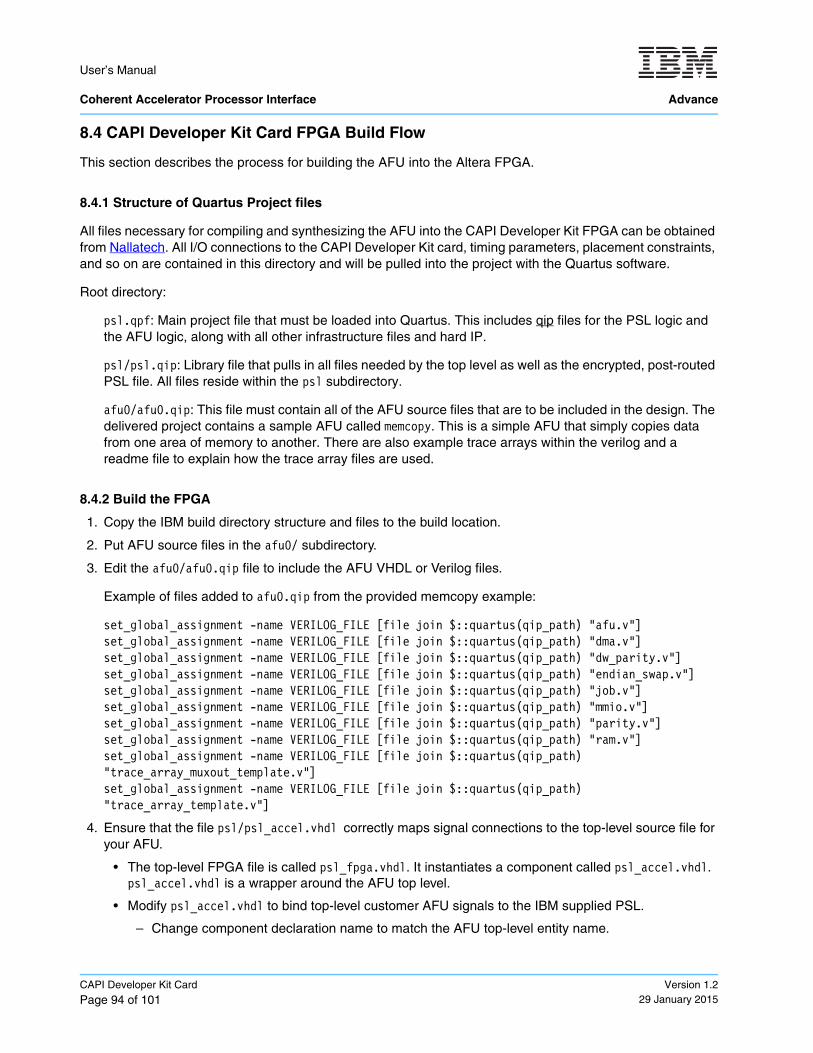
User’s Manual Coherent Accelerator Processor Interface Advance
CAPI Developer Kit Card
Page 94 of 101Version 1.2
29 January 2015
8.4 CAPI Developer Kit Card FPGA Build Flow
This section describes the process for building the AFU into the Altera FPGA.
8.4.1 Structure of Quartus Project files
All files necessary for compiling and synthesizing the AFU into the CAPI Developer Kit FPGA can be obtained from Nallatech. All I/O connections to the CAPI Developer Kit card, timing parameters, placement constraints, and so on are contained in this directory and will be pulled into the project with the Quartus software.
Root directory:
psl.qpf: Main project file that must be loaded into Quartus. This includes qip files for the PSL logic and the AFU logic, along with all other infrastructure files and hard IP.
psl/psl.qip: Library file that pulls in all files needed by the top level as well as the encrypted, post-routed PSL file. All files reside within the psl subdirectory.
afu0/afu0.qip: This file must contain all of the AFU source files that are to be included in the design. The delivered project contains a sample AFU called memcopy. This is a simple AFU that simply copies data from one area of memory to another. There are also example trace arrays within the verilog and a readme file to explain how the trace array files are used.
8.4.2 Build the FPGA
1. Copy the IBM build directory structure and files to the build location.
2. Put AFU source files in the afu0/ subdirectory.
3. Edit the afu0/afu0.qip file to include the AFU VHDL or Verilog files.
Example of files added to afu0.qip from the provided memcopy example:
set_global_assignment -name VERILOG_FILE [file join $::quartus(qip_path) "afu.v"]set_global_assignment -name VERILOG_FILE [file join $::quartus(qip_path) "dma.v"]set_global_assignment -name VERILOG_FILE [file join $::quartus(qip_path) "dw_parity.v"]set_global_assignment -name VERILOG_FILE [file join $::quartus(qip_path) "endian_swap.v"]set_global_assignment -name VERILOG_FILE [file join $::quartus(qip_path) "job.v"]set_global_assignment -name VERILOG_FILE [file join $::quartus(qip_path) "mmio.v"]set_global_assignment -name VERILOG_FILE [file join $::quartus(qip_path) "parity.v"]set_global_assignment -name VERILOG_FILE [file join $::quartus(qip_path) "ram.v"]set_global_assignment -name VERILOG_FILE [file join $::quartus(qip_path) "trace_array_muxout_template.v"]set_global_assignment -name VERILOG_FILE [file join $::quartus(qip_path) "trace_array_template.v"]
4. Ensure that the file psl/psl_accel.vhdl correctly maps signal connections to the top-level source file for your AFU.
• The top-level FPGA file is called psl_fpga.vhdl. It instantiates a component called psl_accel.vhdl. psl_accel.vhdl is a wrapper around the AFU top level.
• Modify psl_accel.vhdl to bind top-level customer AFU signals to the IBM supplied PSL.
– Change component declaration name to match the AFU top-level entity name.
Quartus II IP File
User’s Manual
Advance Coherent Accelerator Processor Interface
Version 1.229 January 2015
CAPI Developer Kit Card
Page 95 of 101
– Port and map the AFU entity (VHDL) or module (Verilog) names to psl_accel names.
5. Compile and synthesize the design using Quartus software until timing targets are met. The PSL design unit must always remain a post-fit partition with routing and placement preserved. If routing and place-ment is not preserved, the partition is re-routed and can cause timing misses.
6. Assemble the design using Quartus software to get your complete .sof build.
7. Use Quartus software to obtain the .rbf for loading to the FPGA.
8.4.3 Load FPGA .rbf File onto the CAPI Developer Kit Card
1. Boot system being used to test your AFU.
2. Run <IBM CAPI flash download script> to transfer your bitfile to the FPGA on the CAPI Developer Kit card flash memory. The script name and location is included in the README file.
3. Run <IBM CAPI Developer Kit reset script> to reset the CAPI Developer Kit card. This causes the new image that is in flash memory to be loaded into the FPGA. The script name and location is included in the README file.
4. Run your application.
8.4.4 Timing Closure Hints
A general flow to help close timing after the initial build follows:
1. Run Top, alt_xcvr_reconfig, and psl_accel design units as source with the psl as post-fit with preserva-tion level set to placement and routing (default copied project file settings).
2. If timing is not met, rerun with alt_xcvr_reconfig and psl as post-fit, and Top and psl_accel as post-syn-thesis.
3. If timing is not met, rerun the same as #2 above except with different fitter seeds.
4. If timing is still not met, start over at step #1 to rerun synthesis. You might also want to delete the db/ and incremental_db/ directories to start fresh.
5. In all the above steps, if very large timing misses are occurring, look at AFU design file changes to correct the problem.
8.4.5 Debug Information
Use trace arrays implemented within the AFU to monitor the AFU-PSL interface for any errors. Simulate failing scenarios with the POWER8 Functional Simulator to try and isolate the issue.
User’s Manual Coherent Accelerator Processor Interface Advance
CAPI Developer Kit Card
Page 96 of 101Version 1.2
29 January 2015
User’s Manual
Advance Coherent Accelerator Processor Interface
Version 1.229 January 2015
Glossary
Page 97 of 101
Glossary
ACK Acknowledgment. A transmission that is sent as an affirmative response to a data transmission.
AFU Accelerator functional unit.
ALUT Adaptive lookup table.
AMOR Authority Mask Override Register.
AMR Authority Mask Register.
architecture A detailed specification of requirements for a processor or computer system. It does not specify details of how the processor or computer system must be imple-mented; instead it provides a template for a family of compatible implementations.
AURP Accelerator Utilization Record Pointer.
Big endian A byte-ordering method in memory where the address n of a word corresponds to the most-significant byte. In an addressed memory word, the bytes are ordered (left to right) 0, 1, 2, 3, with 0 being the most-significant byte. See little endian.
Cache High-speed memory close to a processor. A cache usually contains recently accessed data or instructions, but certain cache-control instructions can lock, evict, or otherwise modify the caching of data or instructions.
Caching inhibited A memory update policy in which the cache is bypassed, and the load or store is performed to or from system memory.
A page of storage is considered caching inhibited when the “I” bit has a value of ‘1’ in the page table. Data located in caching inhibited pages cannot be cached at any memory hierarchy that is not visible to all processors and devices in the system. Stores must update the memory hierarchy to a level that is visible to all processors and devices in the system.
CAIA Coherent Accelerator Interface Architecture. Defines an architecture for loosely coupled coherent accelerators. The Coherent Accelerator Interface Architecture provides a basis for the development of accelerators coherently connected to a POWER processor.
CAPI Coherent Accelerator Process Interface.
CAPP Coherent Attached Processor Proxy.
Coherence Refers to memory and cache coherence. The correct ordering of stores to a memory address, and the enforcement of any required cache write-backs during accesses to that memory address. Cache coherence is implemented by a hard-ware snoop (or inquire) method, which compares the memory addresses of a load request with all cached copies of the data at that address. If a cache contains a modified copy of the requested data, the modified data is written back to memory before the pending load request is serviced.
CSRP Context Save/Restore Area Pointer.
User’s Manual Coherent Accelerator Processor Interface Advance
Glossary
Page 98 of 101Version 1.2
29 January 2015
DLL Delay locked loop.
DMA Direct memory access. A technique for using a special-purpose controller to generate the source and destination addresses for a memory or I/O transfer.
DSISR Data Storage Interrupt Status Register.
DSP Digital signal processor.
EAH PSL effective address high.
EAL PSL effective address low.
EA Effective address. An address generated or used by a program to reference memory. A memory-management unit translates an effective address to a virtual address, which it then translates to a real address (RA) that accesses real (phys-ical) memory. The maximum size of the effective-address space is 264 bytes.
ELF Executable and linkable format.
ERAT Effective-to-real-address translation, or a buffer or table that contains such transla-tions, or a table entry that contains such a translation.
Exception An error, unusual condition, or external signal that can alter a status bit and causes a corresponding interrupt, if the interrupt is enabled. See interrupt.
Fetch Retrieving instructions from either the cache or system memory and placing them into the instruction queue.
FPGA Field-programmable gate array.
HAURP Hypervisor Accelerator Utilization Record Pointer.
hcall Hypervisor call.
HPC Highest point of coherency.
Hypervisor A control (or virtualization) layer between hardware and the operating system. It allocates resources, reserves resources, and protects resources among (for example) sets of AFUs that may be running under different operating systems.
IHPC The owner of the line is the highest point of coherency but it is holding the line in an “I” state.
Implementation A particular processor that conforms to the architecture but might differ from other architecture-compliant implementations. For example, in design this could be the feature set and implementation of optional features.
INT Interrupt. A change in machine state in response to an exception. See exception.
Interrupt packet Used to signal an interrupt, typically to a processor or to another interruptible device.
ISA Instruction set architecture.
JEA Job effective address.

User’s Manual
Advance Coherent Accelerator Processor Interface
Version 1.229 January 2015
Glossary
Page 99 of 101
KB Kilobyte.
LA A local storage (LS) address of an PSL list. It is used as a parameter in an PSL command.
Least-significant bit The bit of least value in an address, register, data element, or instruction encoding.
Little endian A byte-ordering method in memory where the address n of a word corresponds to the least-significant byte. In an addressed memory word, the bytes are ordered (left to right) 3, 2, 1, 0, with 3 being the most-significant byte. See big endian.
LISN Logical interrupt service number.
Logical partitioning A function of an operating system that enables the creation of logical partitions.
LPAR Logical partitioning.
LPC Lowest point of coherency.
LPID Logical-partition identity.
LSb Least-significant bit
LSB Least-significant byte
Main storage The effective-address space. It consists physically of real memory (whatever is external to the memory-interface controller), Local Storage, memory-mapped registers and arrays, memory-mapped I/O devices, and pages of virtual memory that reside on disk. It does not include caches or execution-unit register files.
Mask A pattern of bits used to accept or reject bit patterns in another set of data. Hard-ware interrupts are enabled and disabled by setting or clearing a string of bits, with each interrupt assigned a bit position in a mask register.
MB Megabyte.
Memory coherency An aspect of caching in which it is ensured that an accurate view of memory is provided to all devices that share system memory.
Memory mapped Mapped into the Coherent Attached Accelerator’s addressable-memory space. Registers, local storage (LS), I/O devices, and other readable or writable storage can be memory-mapped. Privileged software does the mapping.
MMIO Memory-mapped I/O.
PID Process ID.
PSL POWER service layer. It is the interface logic for a coherently attached accelerator and provides two main functions: moves data between accelerator function units (AFUs) and main storage, and synchronizes the transfers with the rest of the processing units in the system.
MMIO Memory-mapped input/output. See memory mapped.
User’s Manual Coherent Accelerator Processor Interface Advance
Glossary
Page 100 of 101Version 1.2
29 January 2015
MMU Memory management unit. A functional unit that translates between effective addresses (EAs) used by programs and real addresses (RAs) used by physical memory. The MMU also provides protection mechanisms and other functions.
Most-significant bit The highest-order bit in an address, registers, data element, or instruction encoding.
MRU See most recently used.
MSb Most-significant bit.
Page A region in memory. The Power ISA defines a page as a 4 KB area of memory, aligned on a 4 KB boundary or a large-page size which is implementation depen-dent.
Page table A table that maps virtual addresses (VAs) to real addresses (RAs) and contains related protection parameters and other information about memory locations.
PCIe Peripheral Component Interconnect Express.
PLL Phase locked loop.
POWER Of or relating to the Power ISA or the microprocessors that implement this architecture.
Power ISA A computer architecture that is based on the third generation of reduced instruction set computer (RISC) processors. The Power ISA was developed by IBM.
Privileged mode Also known as supervisor mode. The permission level of operating system instruc-tions. The instructions are described in PowerPC Architecture, Book III and are required of software that accesses system-critical resources.
Privileged software Software that has access to the privileged modes of the architecture.
Problem state The permission level of user instructions. The instructions are described in Power ISA, Books I and II and are required of software that implements application programs.
PSL POWER service layer.
PTE Page table entry. See page table.
RA Real address.
RAM Random access memory.
RA Real address. An address for physical storage, which includes physical memory, local storage (LS), and memory mapped I/O registers. The maximum size of the real-address space is 262 bytes.
SAO Strict address ordering.
SLB Segment lookaside buffer. It is used to map an effective address to a virtual address.
User’s Manual
Advance Coherent Accelerator Processor Interface
Version 1.229 January 2015
Glossary
Page 101 of 101
SPA Scheduled processes area.
SSTP Storage segment table pointer.
Storage model A CAPI User’s Manual-compliant accelerator implements a storage model consis-tent with the Power ISA. For more information about storage models, see the Coherent Accelerator Interface Architecture document.
SUE Special uncorrectable error.
TAG PSL command tag.
Tag group A group of PSL commands. Each PSL command is tagged with an n-bit tag group identifier. An AFU can use this identifier to check or wait on the completion of all queued commands in one or more tag groups.
TG Tag parameter.
TID Thread ID.
TLB Translation lookaside buffer. An on-chip cache that translates virtual addresses (VAs) to real addresses (RAs). A TLB caches page-table entries for the most recently accessed pages, thereby eliminating the necessity to access the page table from memory during load-store operations.
UAMOR User Authority Mask Override.
VA Virtual address. An address to the virtual-memory space, which is typically much larger than the real address space and includes pages stored on disk. It is trans-lated from an effective address by a segmentation mechanism and used by the paging mechanism to obtain the real address (RA). The maximum size of the virtual-address space is 265 bytes.
VHDL VHSIC Hardware Description Language.
WED Work element descriptor.