COFFEE ROASTER VENTILATION HOOD … ROASTER VENTILATION HOOD INSTALLATION AND OPERATING ......
14
4046061-E sonofresco 1365 Pacific Drive Burlington, WA 98233 360-757-2800 COFFEE ROASTER VENTILATION HOOD INSTALLATION AND OPERATING INSTRUCTIONS
Transcript of COFFEE ROASTER VENTILATION HOOD … ROASTER VENTILATION HOOD INSTALLATION AND OPERATING ......

1 4046061-E
sonofresco
1365 Pacific Drive
Burlington, WA 98233
360-757-2800
COFFEE ROASTER VENTILATION HOOD
INSTALLATION AND OPERATING INSTRUCTIONS
2 4046061-E
Figure 1
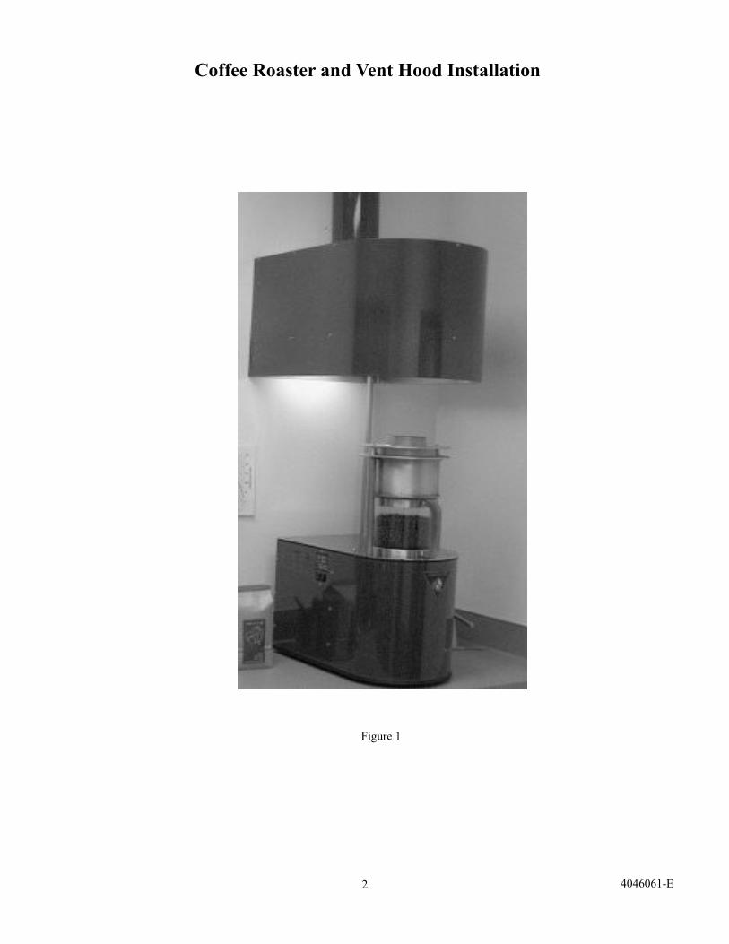
Coffee Roaster and Vent Hood Installation
3 4046061-E
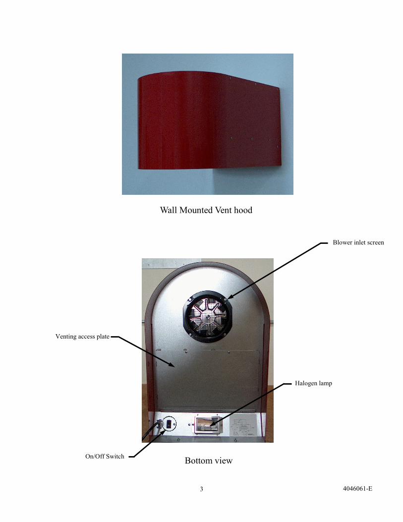
Wall Mounted Vent hood
Bottom view
Halogen lamp
Blower inlet screen
On/Off Switch
Venting access plate
4 4046061-E
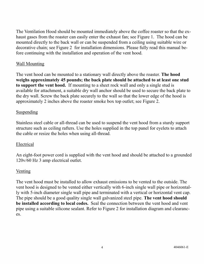
The Ventilation Hood should be mounted immediately above the coffee roaster so that the ex-
haust gases from the roaster can easily enter the exhaust fan; see Figure 1. The hood can be
mounted directly to the back wall or can be suspended from a ceiling using suitable wire or
decorative chain; see Figure 2 for installation dimensions. Please fully read this manual be-
fore continuing with the installation and operation of the vent hood.
Wall Mounting
The vent hood can be mounted to a stationary wall directly above the roaster. The hood
weighs approximately 45 pounds; the back plate should be attached to at least one stud
to support the vent hood. If mounting to a sheet rock wall and only a single stud is
available for attachment, a suitable dry wall anchor should be used to secure the back plate to
the dry wall. Screw the back plate securely to the wall so that the lower edge of the hood is
approximately 2 inches above the roaster smoke box top outlet; see Figure 2.
Suspending
Stainless steel cable or all-thread can be used to suspend the vent hood from a sturdy support
structure such as ceiling rafters. Use the holes supplied in the top panel for eyelets to attach
the cable or resize the holes when using all-thread.
Electrical
An eight-foot power cord is supplied with the vent hood and should be attached to a grounded
120v/60 Hz 3 amp electrical outlet.
Venting
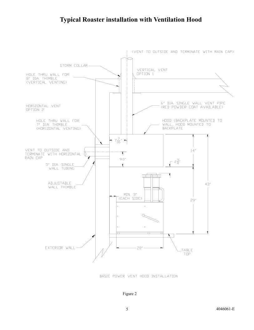
The vent hood must be installed to allow exhaust emissions to be vented to the outside. The
vent hood is designed to be vented either vertically with 6-inch single wall pipe or horizontal-
ly with 5-inch diameter single wall pipe and terminated with a vertical or horizontal vent cap.
The pipe should be a good quality single wall galvanized steel pipe. The vent hood should
be installed according to local codes. Seal the connection between the vent hood and vent
pipe using a suitable silicone sealant. Refer to Figure 2 for installation diagram and clearanc-
es.
5 4046061-E
Typical Roaster installation with Ventilation Hood
Figure 2
6 4046061-E
INSTALLATION
The vent hood mounts to the back panel, which is attached to a solid support wall. Remove
the vent hood back panel from the vent hood as shown in the following pictures and drill
holes through the back panel for mounting to the wall. The vent hood can also be supported
from the top plate using cable or all-thread; four holes in the top plate are provided for at-
taching cable eyelets or all-thread. The following instructions are basic suggestions for a
common installation; it is advised to practice safe construction techniques when in-
stalling the vent hood to prevent damage to person or equipment during operation.
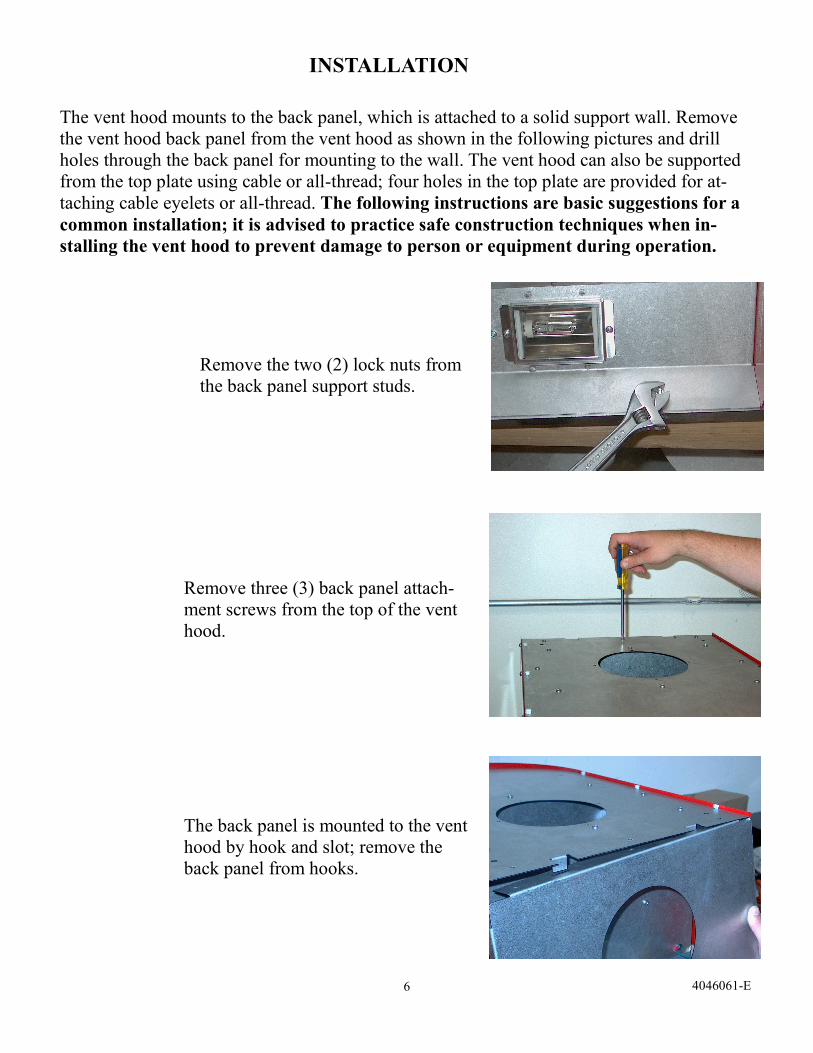
Remove the two (2) lock nuts from
the back panel support studs.
Remove three (3) back panel attach-
ment screws from the top of the vent
hood.
The back panel is mounted to the vent
hood by hook and slot; remove the
back panel from hooks.
7 4046061-E
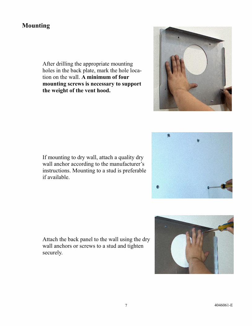
After drilling the appropriate mounting
holes in the back plate, mark the hole loca-
tion on the wall. A minimum of four
mounting screws is necessary to support
the weight of the vent hood.
If mounting to dry wall, attach a quality dry
wall anchor according to the manufacturer’s
instructions. Mounting to a stud is preferable
if available.
Attach the back panel to the wall using the dry
wall anchors or screws to a stud and tighten
securely.
Mounting
8 4046061-E
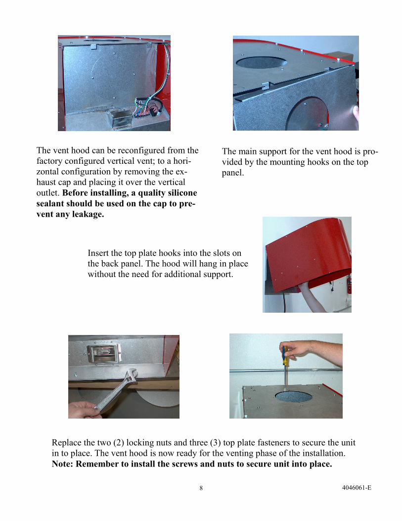
The vent hood can be reconfigured from the
factory configured vertical vent; to a hori-
zontal configuration by removing the ex-
haust cap and placing it over the vertical
outlet. Before installing, a quality silicone
sealant should be used on the cap to pre-
vent any leakage.
The main support for the vent hood is pro-
vided by the mounting hooks on the top
panel.
Insert the top plate hooks into the slots on
the back panel. The hood will hang in place
without the need for additional support.
Replace the two (2) locking nuts and three (3) top plate fasteners to secure the unit
in to place. The vent hood is now ready for the venting phase of the installation.
Note: Remember to install the screws and nuts to secure unit into place.
9 4046061-E
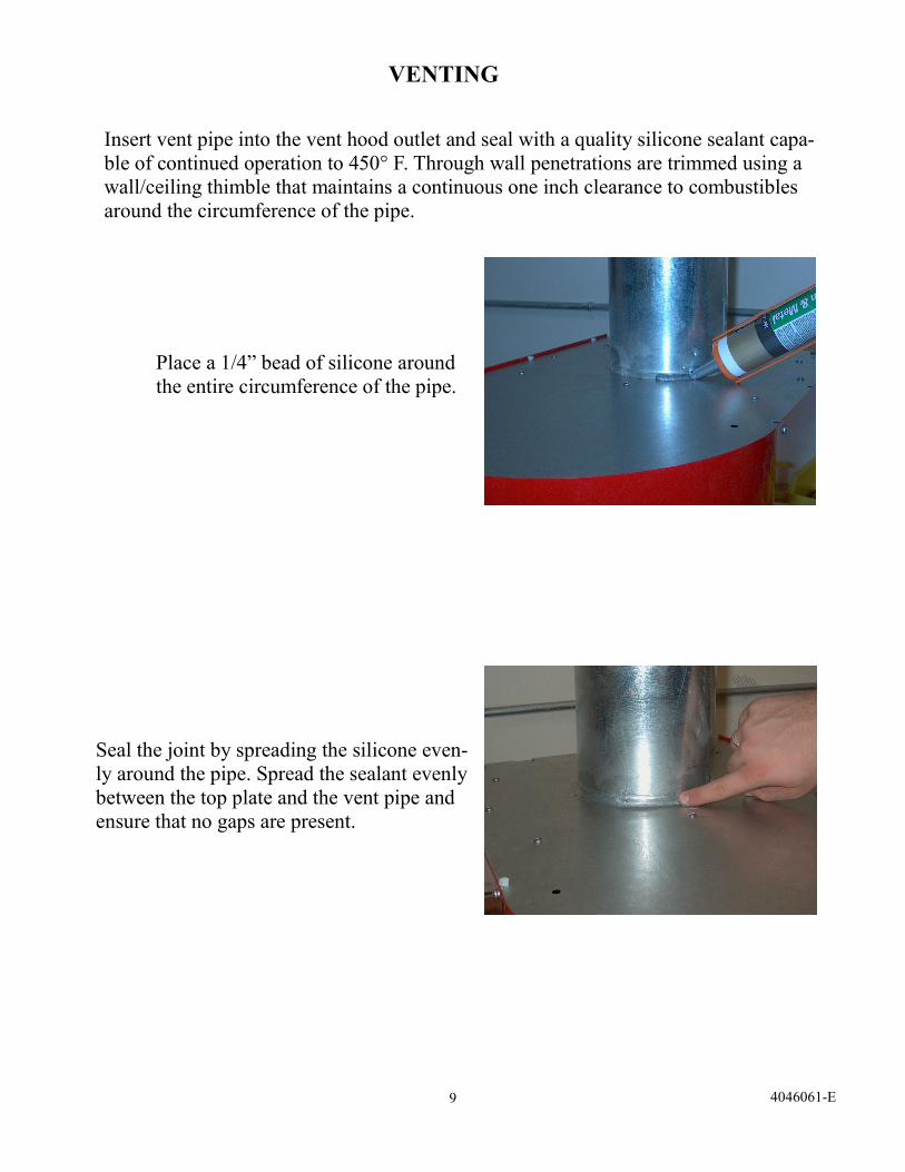
Insert vent pipe into the vent hood outlet and seal with a quality silicone sealant capa-
ble of continued operation to 450° F. Through wall penetrations are trimmed using a
wall/ceiling thimble that maintains a continuous one inch clearance to combustibles
around the circumference of the pipe.
Seal the joint by spreading the silicone even-
ly around the pipe. Spread the sealant evenly
between the top plate and the vent pipe and
ensure that no gaps are present.
Place a 1/4” bead of silicone around
the entire circumference of the pipe.
VENTING
10 4046061-E
Operation
Turn the rocker switch to the ON position prior to starting the roaster. This will start the ex-
haust fan and turn on the light mounted underneath the hood. When the roast is completed,
turn the switch to the OFF position. Never operate the roaster without the vent hood turned
on; doing so will cause improper venting of the roaster exhaust.
Maintenance
The vent hood should be regularly maintained for the best possible performance. Always
disconnect the appliance from the power source before performing any maintenance.
Clean the inlet screen to remove dust and oils with a wire brush at least weekly. The outside
surface of the screen can be cleaned with a wire brush without removal of the screen. Re-
moval of the screen will be required for more extensive cleaning. Follow the instructions
on the following page for screen removal. Failure to clean the inlet screen will reduce the
air flow potential of the vent hood. See figure 4.
Although the impellor is designed to be self cleaning, it is recommended that the blower
impellor and the interior of the blower housing be cleaned periodically to remove build-up
as needed. See Figure 5.
Build up in the venting system will reduce the air flow potential of the vent hood. Clean the
vent pipe system regularly to avoid build up of dust and oils. See Figure 6
A chimney brush can be purchased from most hardware stores for use in cleaning the vent
system.
Note: The duration between the vent system and blower housing cleanings is dependent on the
amount of coffee roasted and the roast level. Higher roast levels produce greater levels of oils
that will increase the rate of build-up. Evaluation of the these areas should occur monthly in
order to develop a suitable maintenance schedule. Duration of cleaning should not exceed one
month for the blower housing and impellor and six months for the venting system.
11 4046061-E
Figure 3
Figure 4
Figure 5
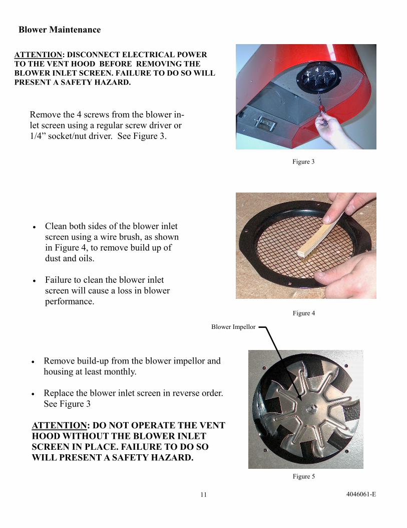
Clean both sides of the blower inlet
screen using a wire brush, as shown
in Figure 4, to remove build up of
dust and oils.
Failure to clean the blower inlet
screen will cause a loss in blower
performance.
Remove the 4 screws from the blower in-
let screen using a regular screw driver or
1/4” socket/nut driver. See Figure 3.
Remove build-up from the blower impellor and
housing at least monthly.
Replace the blower inlet screen in reverse order.
See Figure 3
ATTENTION: DO NOT OPERATE THE VENT
HOOD WITHOUT THE BLOWER INLET
SCREEN IN PLACE. FAILURE TO DO SO
WILL PRESENT A SAFETY HAZARD.
ATTENTION: DISCONNECT ELECTRICAL POWER
TO THE VENT HOOD BEFORE REMOVING THE
BLOWER INLET SCREEN. FAILURE TO DO SO WILL
PRESENT A SAFETY HAZARD.
Blower Impellor
Blower Maintenance
12 4046061-E
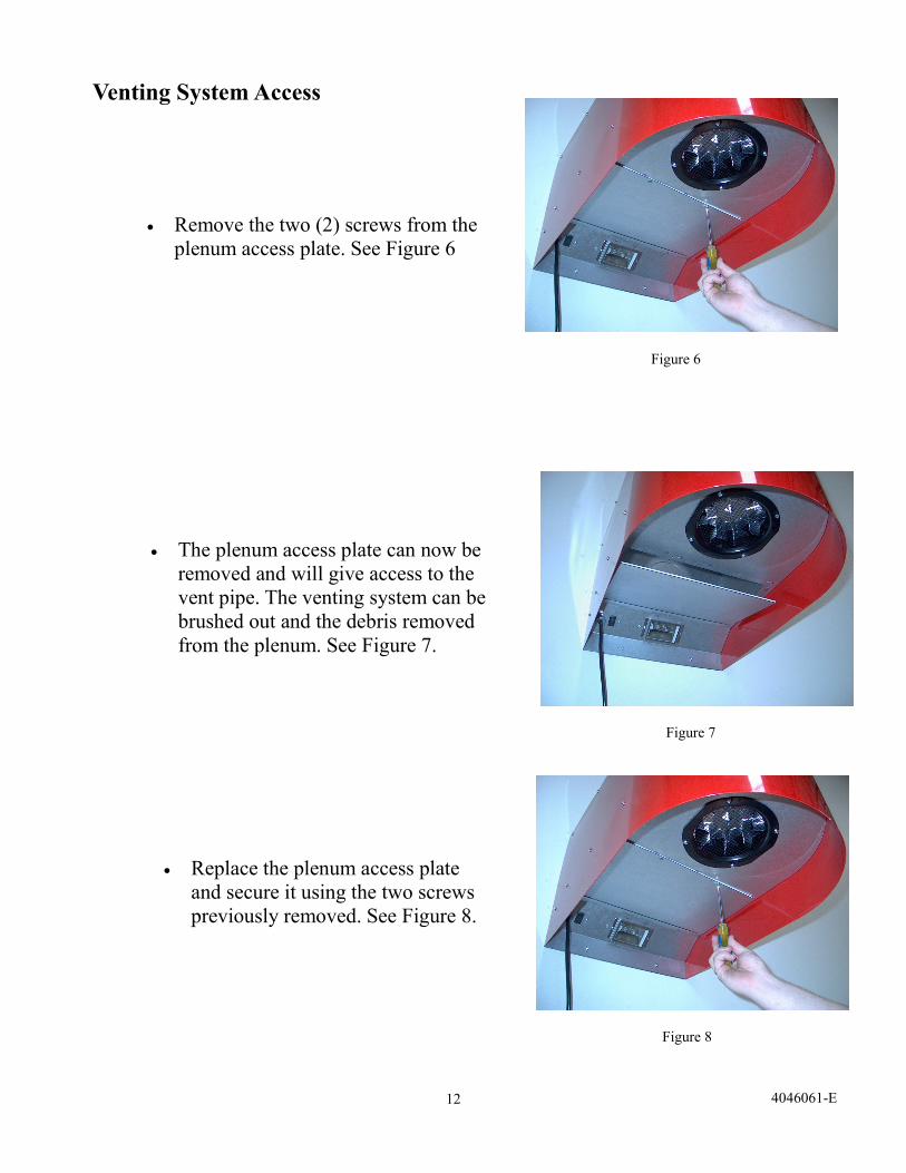
Remove the two (2) screws from the
plenum access plate. See Figure 6
Figure 6
Figure 7
Figure 8
The plenum access plate can now be
removed and will give access to the
vent pipe. The venting system can be
brushed out and the debris removed
from the plenum. See Figure 7.
Replace the plenum access plate
and secure it using the two screws
previously removed. See Figure 8.
Venting System Access
13 4046061-E
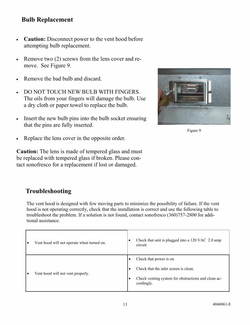
Caution: Disconnect power to the vent hood before
attempting bulb replacement.
Remove two (2) screws from the lens cover and re-
move. See Figure 9.
Remove the bad bulb and discard.
DO NOT TOUCH NEW BULB WITH FINGERS.
The oils from your fingers will damage the bulb. Use
a dry cloth or paper towel to replace the bulb.
Insert the new bulb pins into the bulb socket ensuring
that the pins are fully inserted.
Replace the lens cover in the opposite order.
Caution: The lens is made of tempered glass and must
be replaced with tempered glass if broken. Please con-
tact sonofresco for a replacement if lost or damaged.
Figure 9
Bulb Replacement
Troubleshooting
The vent hood is designed with few moving parts to minimize the possibility of failure. If the vent
hood is not operating correctly, check that the installation is correct and use the following table to
troubleshoot the problem. If a solution is not found, contact sonofresco (360)757-2800 for addi-
tional assistance.
Vent hood will not operate when turned on. Check that unit is plugged into a 120 VAC 2.0 amp
circuit.
Vent hood will not vent properly.
Check that power is on.
Check that the inlet screen is clean.
Check venting system for obstructions and clean ac-
cordingly.
14 4046061-E
Specifications:
Electrical:
120 volts, 1.0 amps
Ventilation:
Flow rate: 180 cfm @ 0.2 inches water column.
Vent Pipe: 6” diameter single wall galvanized steel for top vent connection (vertical vent)
5” diameter single wall galvanized steel for rear connection ( horizontal vent)
Max Pipe length (5 or 6 in.) = 25 ft horizontal
= 40 ft vertical
Max number 90° bends = 3
A wall or ceiling thimble to provide 1 inch clearance between vent pipe and wall/ ceiling penetration.
Terminate with a rain cap.
6” diameter single wall galvanized steel powder coated red, to match the roaster, is available on request.