Coding and Modulation in Cameras - MIT Media Lab
64
Mitsubishi Electric Research Labs (MERL) Cambridge, MA Coding and Modulation in Cameras Coding and Modulation in Cameras Ramesh Raskar with Ashok Veeraraghavan, Amit Agrawal, Jack Tumblin, Ankit Mohan
Transcript of Coding and Modulation in Cameras - MIT Media Lab

Mitsubishi Electric Research Laboratories Raskar 2007
Mitsubishi Electric Research Labs (MERL)Cambridge, MA
Coding and Modulation in CamerasCoding and Modulation in Cameras
Ramesh Raskarwith Ashok Veeraraghavan, Amit Agrawal, Jack Tumblin, Ankit Mohan

OverviewOverview
• Coded Exposure– Motion Deblurring
• Coded Aperture– Digital Refocussing
• Extended depth of field
– Optical Heterodyning• Light Field Capture• 4D to 2D mapping
Coding in Time
Coding in Space

Motion Blurred Input Photo

Image Deblurred by solving a linear system. No post-processing
Approximate rectified crop of photo

Flutter Shutter CameraFlutter Shutter CameraRaskar, Agrawal, Tumblin [Siggraph2006]
Ferroelectric LCD shutter in front of the lens is turnedopaque or transparent in a rapid binary sequence

Short Exposure Traditional MURA Coded
Coded Exposure Photography: Assisting Motion Deblurring using Fluttered Shutter
Deblurred Result
Captured SinglePhoto
Shutter
Result has Banding Artifacts and some spatial
frequencies are lost
Decoded image is as good as image of a
static scene
Image is dark and noisy

Exposure choices for capturing fast moving objects
Keep Shutter open for entire exposure duration
The moving object creates smear
Flutter shutter open and closed with a psuedo-random binary sequence within exposure durationto encode the blur
Keep shutter open for very shortduration. Avoids blur but image is dark and suffers from noise.
Time
Time
Shutter On
Traditional Camera
Coded Exposure CameraShutter Off
Shutter On
Shutter Off
TimeShort Exposure
Shutter On
Shutter Off


Coded Motion Blur = Preserves high spatial frequencies= Deconvolution filter frequency response is nearly flat= Deconvolution becomes a well-posed problem
Encoding Filter (Blurring) Decoding Filter (Deblurring)
pi/5 2pi/5 3pi/5 4pi/5 pi0
10
20
30
40
50
60
Frequency
Log
Mag
nitu
deFlatOurs
pi/5 2pi/5 3pi/5 4pi/5 pi−60
−50
−40
−30
−20
−10
0
Frequency
Log
Mag
nitu
de
FlatOurs

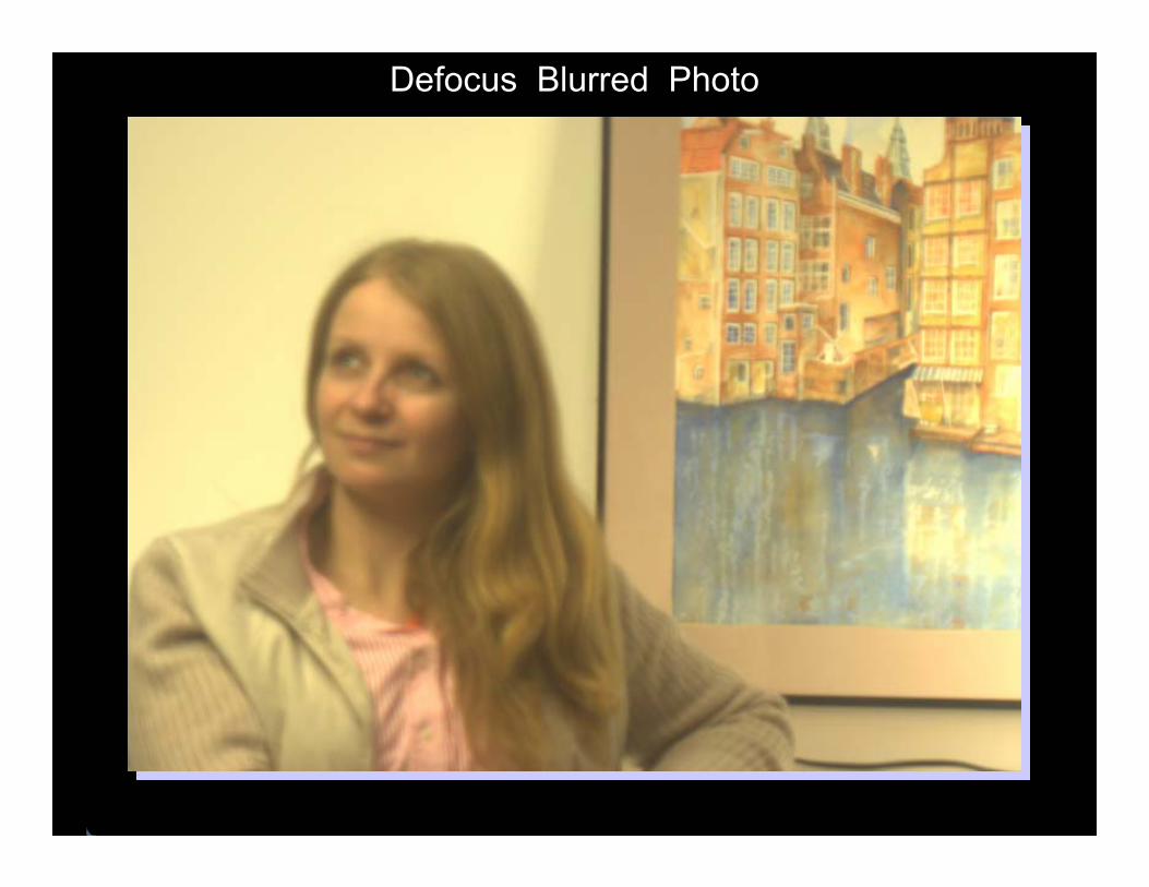
Defocus Blurred Photo

Digital Refocusing
Refocused Image on Person

Coded Coded ExposureExposure Coded Coded ApertureAperture
Temporal 1Temporal 1--D D broadband codebroadband code
Spatial 2Spatial 2--D D broadband codebroadband code

Digital Refocusing

Coded Aperture CameraCoded Aperture Camera
The aperture of a 100 mm lens is modified
Rest of the camera is unmodified
Insert a coded mask with chosen binary pattern


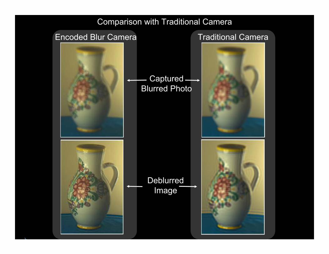
Comparison with Traditional Camera
Captured Blurred Photo
Deblurred Image
Encoded Blur Camera Traditional Camera

Comparison with Small Aperture Image
Captured Blurred Image
Small Aperture Image
Deblurred Image

Digital Refocusing
Captured Blurred Image

Digital Refocusing
Refocused Image on Person

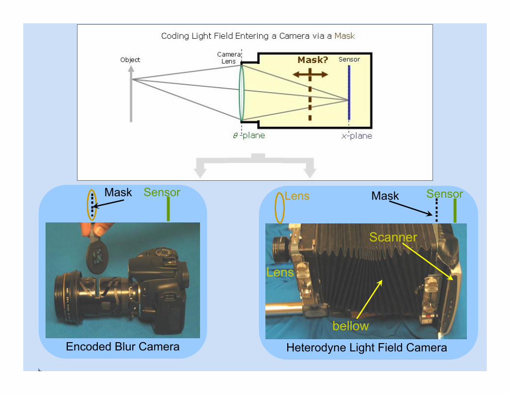
Can we capture more information by inserting a mask ?


Mask Sensor
Encoded Blur Camera
Scanner
Lens
Mask SensorLens
Heterodyne Light Field Camera
bellow
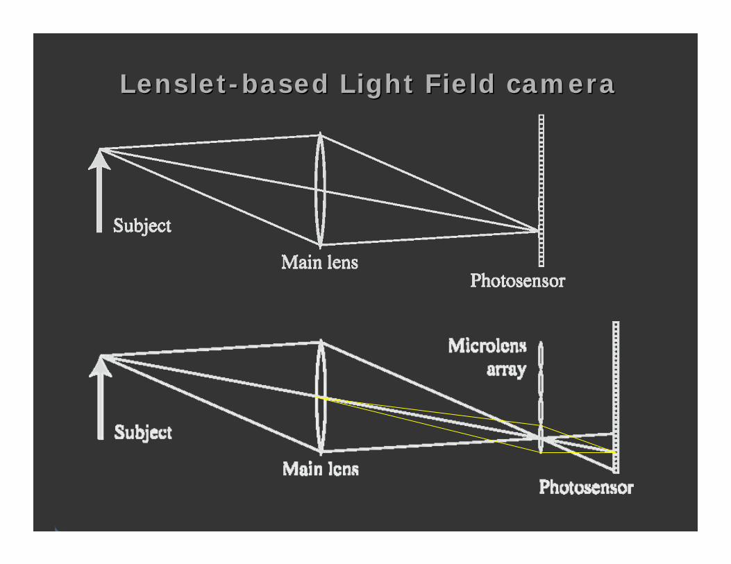
LensletLenslet--based Light Field camerabased Light Field camera
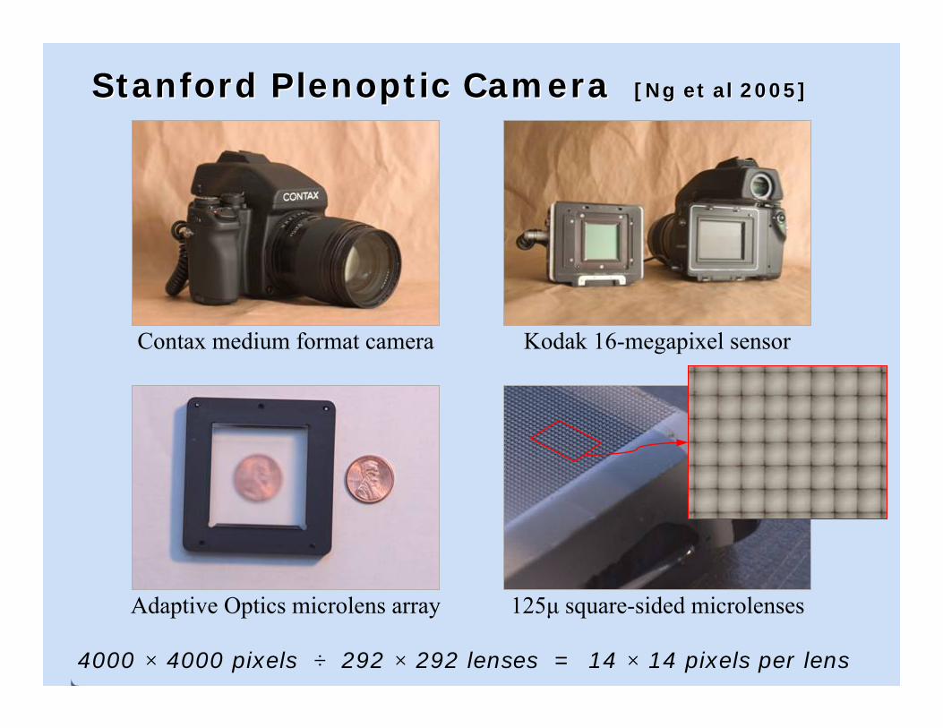
Stanford Plenoptic Camera Stanford Plenoptic Camera [Ng et al 2005][Ng et al 2005]
4000 × 4000 pixels ÷ 292 × 292 lenses = 14 × 14 pixels per lens
Contax medium format camera Kodak 16-megapixel sensor
Adaptive Optics microlens array 125μ square-sided microlenses


Digital RefocusingDigital Refocusing((LensletLenslet array)array)
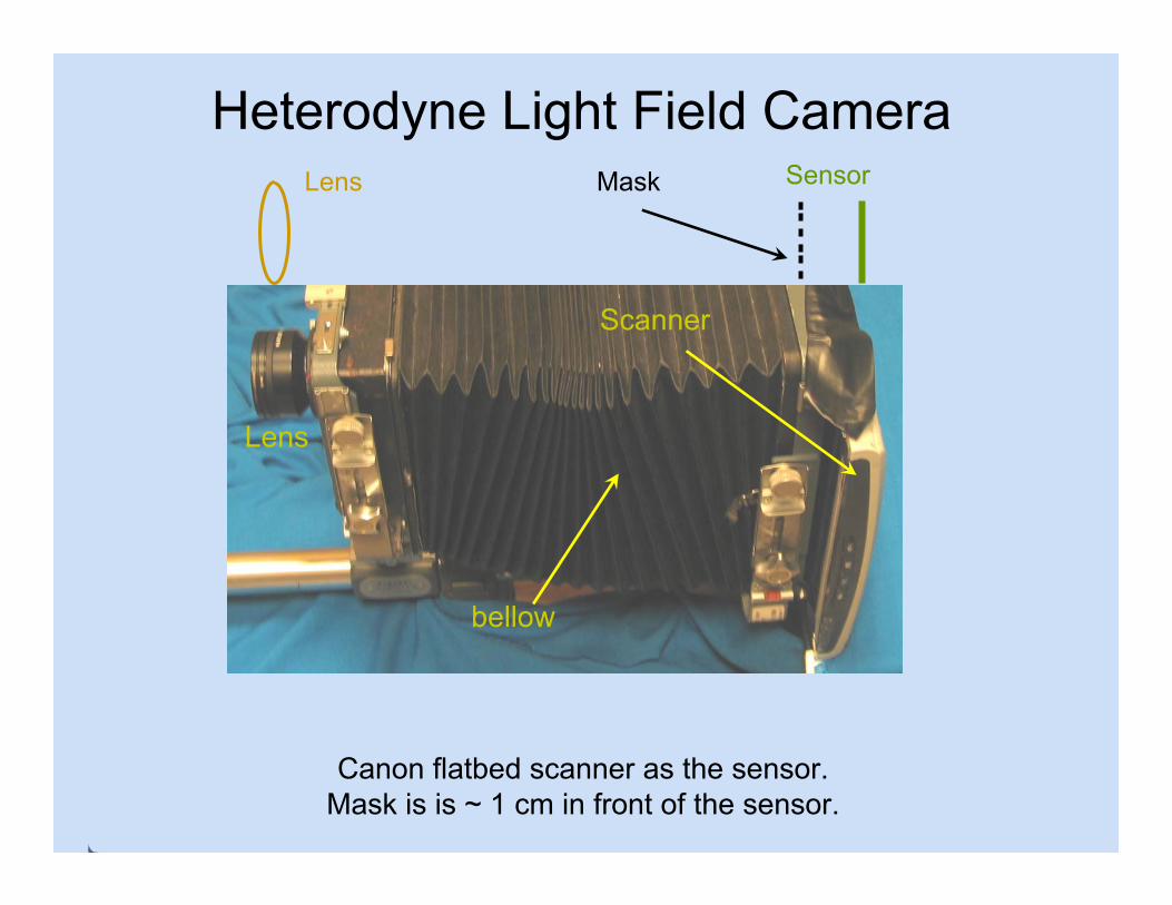
Canon flatbed scanner as the sensor. Mask is is ~ 1 cm in front of the sensor.
Scanner
Lens
Mask SensorLens
bellow
Heterodyne Light Field Camera

Capturing 4D light fieldCapturing 4D light field
2D Sensor image Zoom in showing light field encoding


Movie: Movie: Digital Refocusing by taking Digital Refocusing by taking
2D Projections of 4D Light Field2D Projections of 4D Light Field
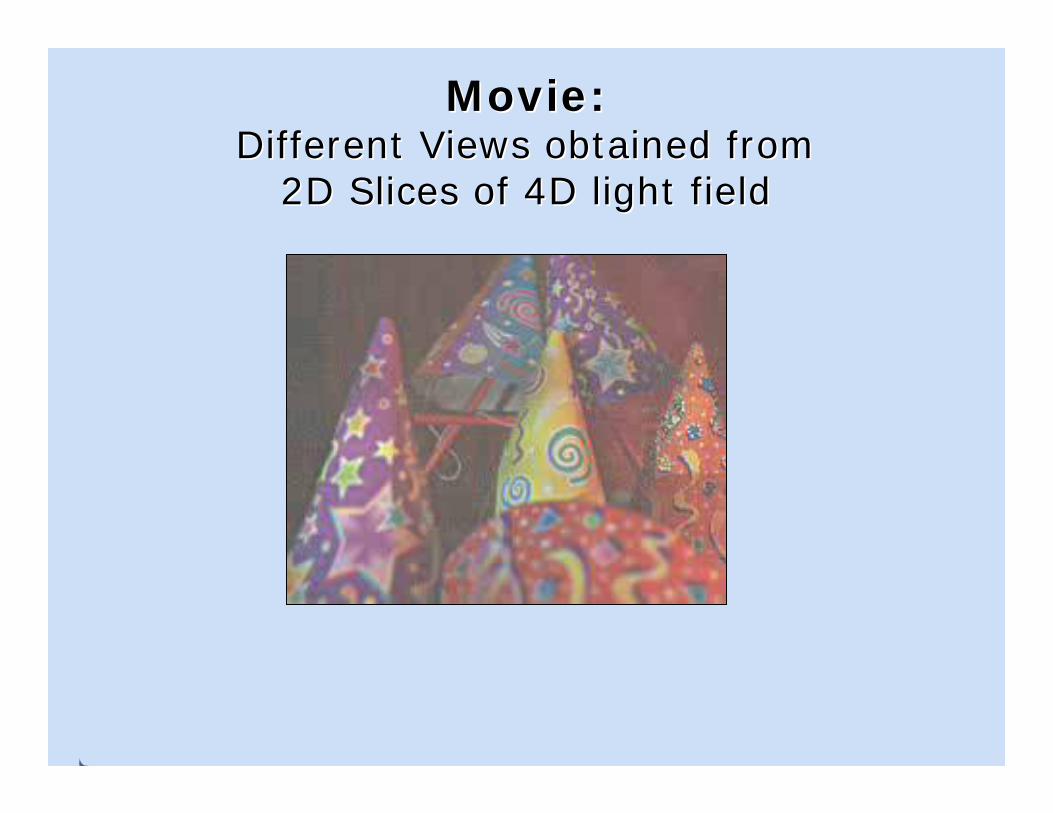
Movie: Movie: Different Views obtained from Different Views obtained from
2D Slices of 4D light field2D Slices of 4D light field

Mask-based Modulation
Main LensObject Mask Sensor
Photographic Signal
(Light Field)
Carrier (High
Frequency)
Incident Modulated
Signal
ReferenceCarrier
RecoveredLight Field
Software Demodulation
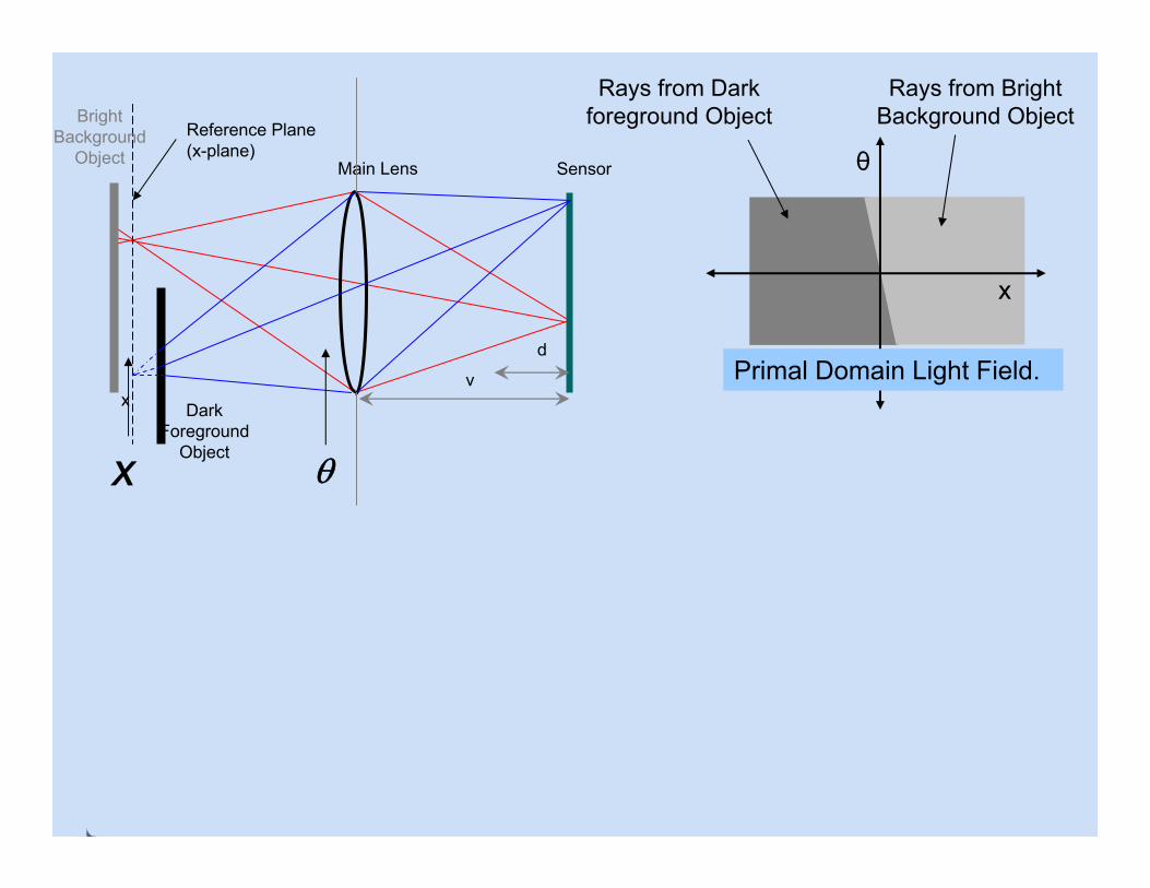
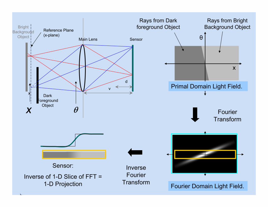
How to Capture a 4D Signal with a 2D Sensor ?

x
θ
Rays from Bright Background Object
Rays from Dark foreground Object
Primal Domain Light Field.
Main Lens
Dark Foreground
Object
Sensor
d
v
Bright Background
ObjectReference Plane (x-plane)
x
X θ
x
θ
Rays from Bright Background Object
Rays from Dark foreground Object
Primal Domain Light Field.
Main Lens
Dark Foreground
Object
Sensor
d
v
Bright Background
ObjectReference Plane (x-plane)
x
X θ
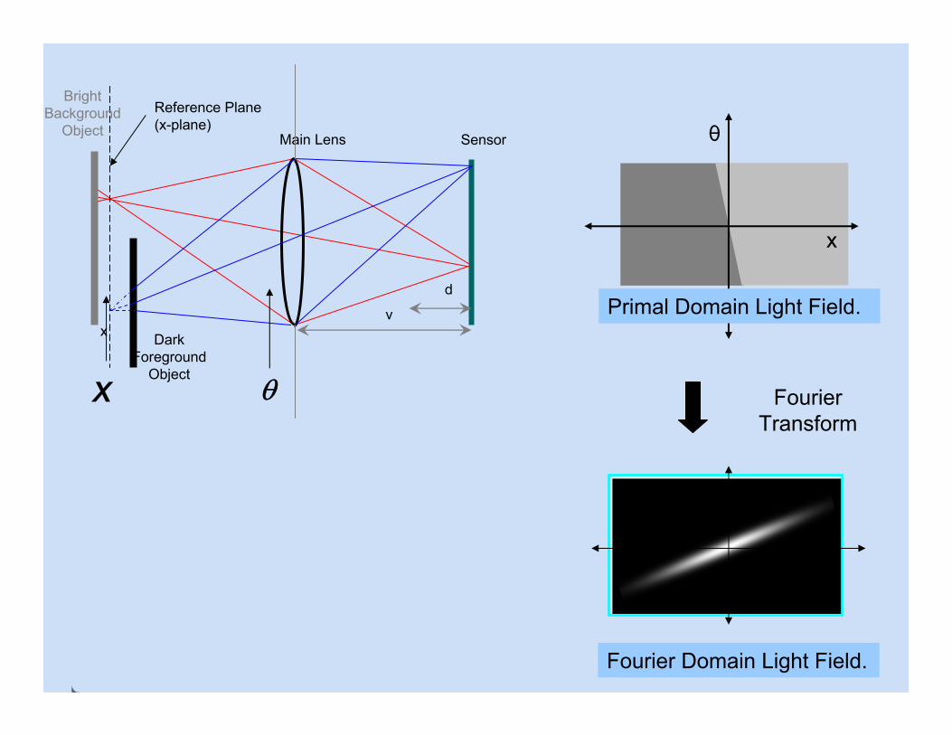
x
θ
Primal Domain Light Field.
Fourier Transform
Fourier Domain Light Field.
Main Lens
Dark Foreground
Object
Sensor
d
v
Bright Background
ObjectReference Plane (x-plane)
x
X θ
x
θ
Rays from Bright Background Object
Rays from Dark foreground Object
Primal Domain Light Field.
Fourier Transform
Fourier Domain Light Field.
Main Lens
Dark Foreground
Object
Sensor
d
v
Bright Background
ObjectReference Plane (x-plane)
x
X θ
InverseFourier
Transform
Sensor:
Inverse of 1-D Slice of FFT = 1-D Projection

Fourier Transform
Fourier Domain Light Field.
Main Lens
Dark Foreground
Object
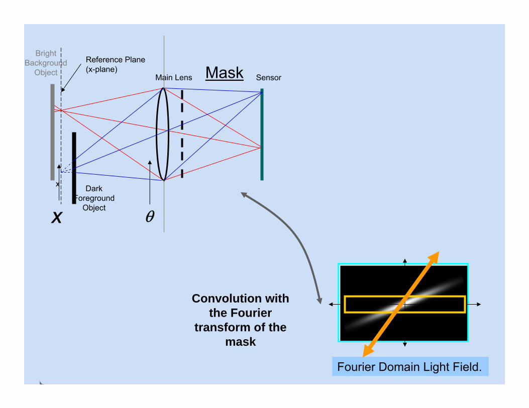
Mask Sensor
Bright Background
ObjectReference Plane (x-plane)
x
X θ
Convolution with the Fourier
transform of the Mask
Incident Light Field = Multiplication with the
Light Field of the mask

Fourier Domain Light Field.
Main Lens
Dark Foreground
Object
Mask Sensor
Bright Background
ObjectReference Plane (x-plane)
x
X θ
Convolution with the Fourier
transform of the mask

Fourier Domain Light Field.
Main Lens
Dark Foreground
Object
Mask Sensor
Bright Background
ObjectReference Plane (x-plane)
x
X θ
Convolution with the Fourier
transform of the mask

Fourier Domain Light Field.
Main Lens
Dark Foreground
Object
Mask Sensor
Bright Background
ObjectReference Plane (x-plane)
x
X θ
Convolution with the Fourier
transform of the mask
Fourier Domain Light Field.
Main Lens
Dark Foreground
Object
Mask Sensor
Bright Background
ObjectReference Plane (x-plane)
x
X θ
Convolution with the Fourier
transform of the mask

Fourier Domain Light Field.
Main Lens
Dark Foreground
Object
Mask Sensor
Bright Background
ObjectReference Plane (x-plane)
x
X θ
Convolution with the Fourier
transform of the mask
Mask Sensor
Encoded Blur Camera
Scanner
Lens
Mask SensorLens
Heterodyne Light Field Camera
bellow

How to Capture 4D Light Field with 2D Sensor ?
fθ
fx
fθ0
fx0
Band-limited Light Field
Sensor Slice
Fourier Light Field Space

Extra sensor bandwidth cannot capture extra dimension of the light field
fθ
fx
fθ0
fx0
Extra sensor bandwidth

fθ
fxSensor Slice
??????
??????

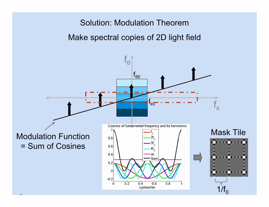
Solution: Modulation Theorem
Make spectral copies of 2D light field
fθ
fx
fθ0
fx0
Modulation Function
Solution: Modulation Theorem
Make spectral copies of 2D light field
fθ
fx
fθ0
fx0
Modulation Function = Sum of Cosines
1/f0
Mask Tile

Mask-based Modulation
Main LensObject Mask Sensor
Photographic Signal
(Light Field)
Carrier (High
Frequency)
Incident Modulated
Signal
ReferenceCarrier
RecoveredLight Field
Software Demodulation
How to Capture a 4D Signal with a 2D Sensor ?

Scanner 1D sensor
Mask = 4 cosines = 9 impulses in Fourier transform = 9 angular samples
Scanner
Lens
bellow
Mask on top of scanner

fθ
Modulated Light Field
fx
fθ0
fx0Sensor Slice
Modulation Function
Sensor slice captures entire Light Field
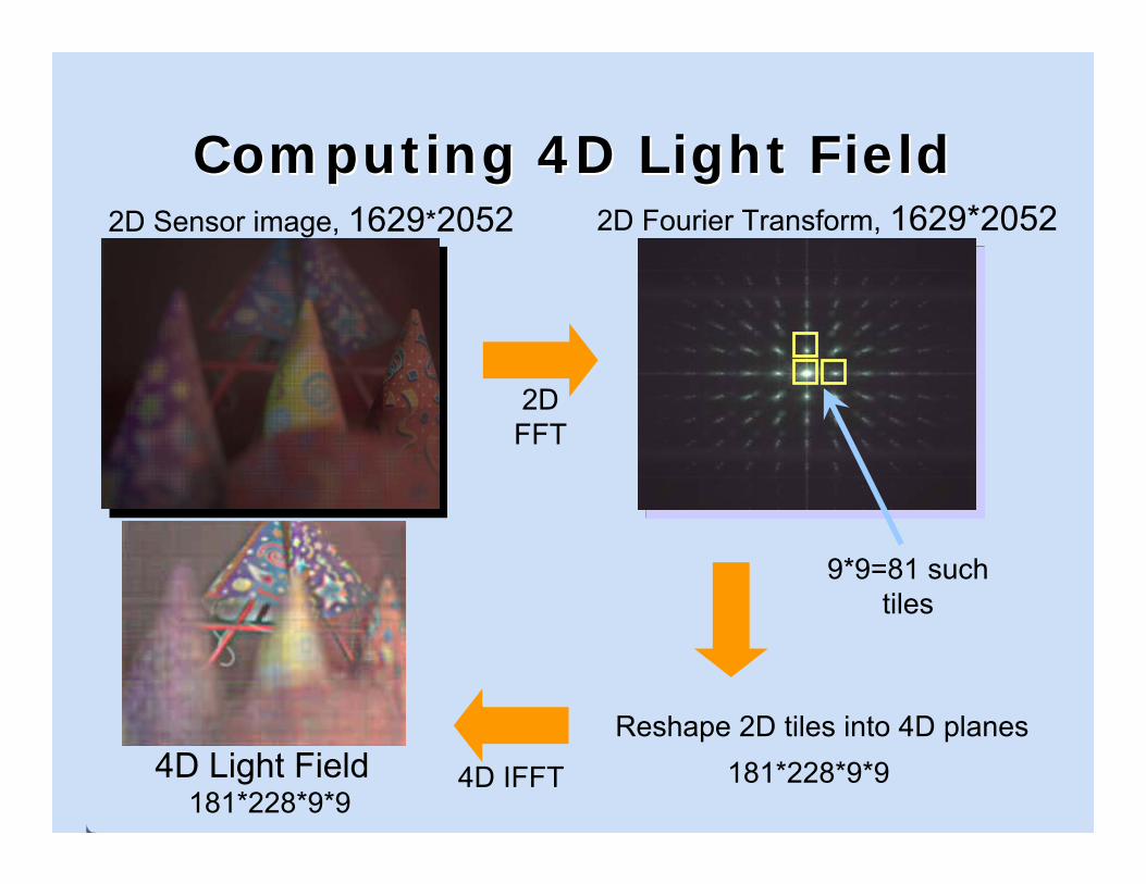
Computing 4D Light FieldComputing 4D Light Field2D Sensor image, 1629*2052 2D Fourier Transform, 1629*2052
2D FFT
Reshape 2D tiles into 4D planes181*228*9*94D IFFT4D Light Field
9*9=81 such tiles
181*228*9*9
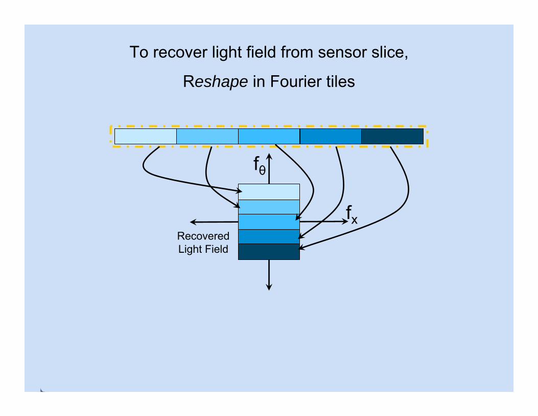
To recover light field from sensor slice,
Reshape in Fourier tiles
fθ
fxRecovered Light Field

Coded Masks For CamerasCoded Masks For Cameras
Scanner
Lens
Mask SensorLens
Heterodyne Light Field Camera
bellow
•Capture Light Field
•Complex refocussing at reduced resolution
•Fine, narrowband mask close to sensor
•Modulation of incoming light field by mask
Mask Sensor
Encoded Blur Camera
•Capture Coded Blur
•Full resolution digital refocussing
•Coarse, broadband mask in aperture
•Convolution of sharp image with mask

Scanner
Lens
Mask SensorLens
Heterodyne Light Field Camera
bellow
Mask Sensor
Encoded Blur Camera
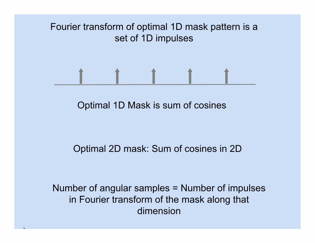
Fourier transform of optimal 1D mask pattern is a set of 1D impulses
Optimal 1D Mask is sum of cosines
Optimal 2D mask: Sum of cosines in 2D
Number of angular samples = Number of impulses in Fourier transform of the mask along that
dimension
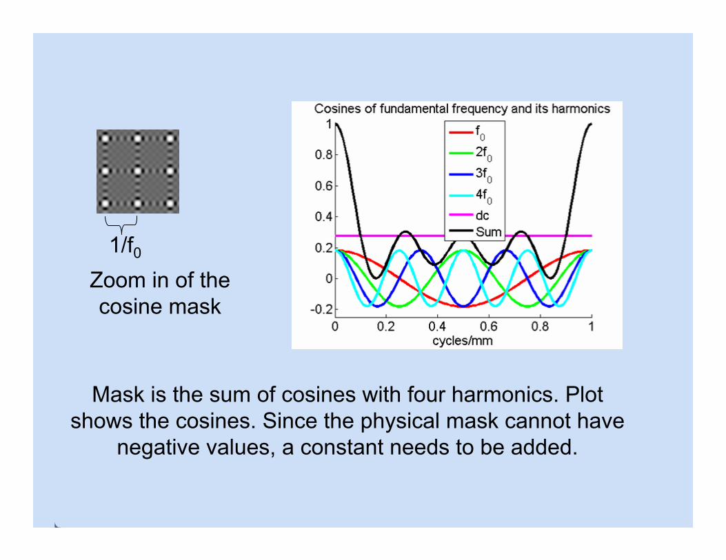
Zoom in of the cosine mask
1/f0
Mask is the sum of cosines with four harmonics. Plot shows the cosines. Since the physical mask cannot have
negative values, a constant needs to be added.
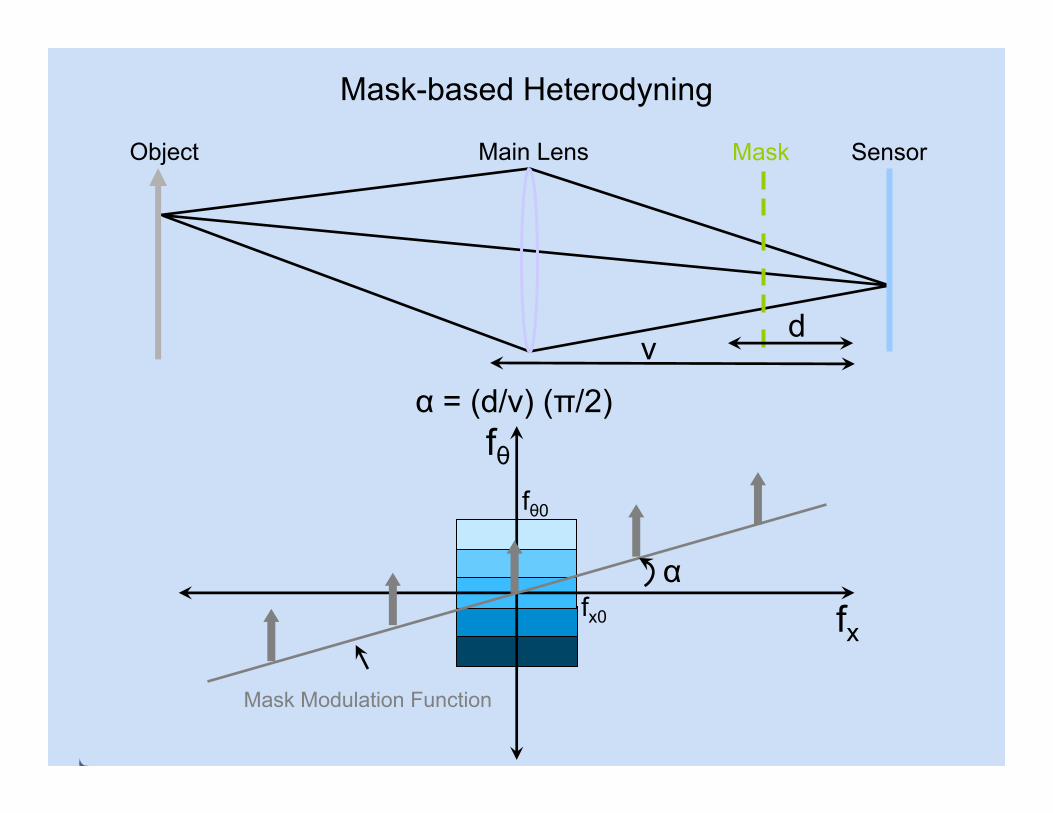
Mask-based Heterodyning
Main LensObject Mask Sensor
fθ
fx
fθ0
fx0
Mask Modulation Function
α
α = (d/v) (π/2)
dv

Implementation
We use Canon flatbed scanner as the sensor and Nikkorlens in front. The mask is placed is about 1 cm in front of
the sensor.
Scanner
Lens
Mask SensorLens
Light Field Camera
bellow