Qualification Number: R685 04 Qualification Specification ...

RESEARCH REPORT VTT-R-01217-13
Codes of practice guidingqualification of components in NPP
Authors: Ludovic Fülöp
Confidentiality: Public


RESEARCH REPORT VTT-R-01217-13
1 (17)
Report’s titleCodes of practice guiding qualification of components in NPPCustomer, contact person, address Order referencehe Finnish Research Programme on Nuclear Power PlantSafety 2011 – 2014Project name Project number/Short nameSeismic Safety of Nuclear Power Plants – Targets for Researchand Education
73688/SESA
Author(s) PagesLudovic Fülöp 18Keywords Report identification codeSeismic Safety, Nuclear Power Plant, Design VTT-R-01217-13SummaryThis report is deliverable for 2012 of Subproject 3 in the project SESA “Seismic Safety ofNuclear Power Plants – Targets for Research and Education”, part of the SAFIR 2014program on nuclear safety.
2012 was the startup year of activity in Subproject 3.
Seismic qualification is more fragmented field compared to design of structures. The available methods,especially for the qualification of installed equipment (may be relevant for the Stress Test), require theuse of large sets of criteria and databases – hence allowing for much larger margin of interpretation.
The aim of the work in this year is to summarize available component qualification databases andqualification procedures available in codes of practice (IEEE 344, ICE 68-3-3and RCC-E).
Confidentiality PublicEspoo 19.2.2013Written by
Ludovic FülöpSenior Research Scientist
Reviewed by
Ilkka Hakola,Senior Research Scientist
Accepted by
Eila Lehmus,Technology Manager
VTT’s contact address
Distribution (customer and VTT){Customer, VTT and other distribution. In confidential reports the company, person andamount of copies must be named. Continue to next page when necessary.}
The use of the name of the VTT Technical Research Centre of Finland (VTT) in advertising or publication in part ofthis report is only permissible with written authorisation from the VTT Technical Research Centre of Finland.

RESEARCH REPORT VTT-R-01217-13
2 (17)
Preface
The decisions to increase the number of nuclear power plants (NPP) in Finland, and especiallythe positioning of one NPP in the northern part of the country, called for reassessing thepotential effect of earthquakes on plant safety requirements.
As a response to this need, the project SESA - Seismic Safety of Nuclear Power Plants –Targets for Research and Education was included in the Finnish Research Program onNuclear Power Plant Safety, SAFIR 2014, under the umbrella of Reference Group 7 -Construction safety. SESA is in its first year of financing in 2011, and it has 3 Subprojects:
Subproject 1. Earthquake hazard assessment,Subproject 2. Structural assessment,Subproject 3. Equipment qualification procedures,
This report is a deliverable of Subproject 3 for the 2012.
The work in SESA has been supervised by the Reference Group 7 and the Ad-Hoc groupspecifically named for the SESA project.
Members of the RG7:Pekka Välikangas STUK (Chair)Jukka Myllymäki STUKVesa Hiltunen TVOTimo Kukkola TVOJoonas Koskinen FORTUMTapani Kukkola FORTUMAki Mattila FORTUMJuha Rinta-Seppälä FENNOVOIMAJari Puttonen Aalto UniversityHeli Koukkari VTTEila Lehmus VTT
Members of the Ad-Hoc group:Pekka Valikangas STUK (Chair)Jorma Sandberg STUKOli Okko STUKJuho Helander FENNOVOIMATimo Kukkola TVOPentti Varpasuo FORTUMMari Vuorinen FORTUMIlkka Laihorinne WärtsiläJari Puttonen Aalto UniversityPekka Heikkinen Uni. of HelsinkiJouni Saari ÅF-Consult
Espoo 19.2.2013
Authors
RESEARCH REPORT VTT-R-01217-13
3 (17)
Contents
Preface ........................................................................................................................ 21 Introduction ............................................................................................................. 42 Goal ........................................................................................................................ 43 Measures for qualifying equipment according to IEEE 344 .................................... 4
3.1 Qualification approaches................................................................................. 53.1.1 Qualification by analysis....................................................................... 53.1.2 Qualification by testing ......................................................................... 63.1.3 Qualification by testing and analysis .................................................... 6
3.2 Test methods .................................................................................................. 73.3 Extrapolation from similar equipment & multi-cabinet assemblies .................. 83.4 Qualification by experience ............................................................................. 83.5 Shock testing .................................................................................................. 9
4 Qualifying equipment according to CEI/IEC 68-3-3 ................................................ 94.1 Qualification consideration and general procedures ..................................... 104.2 Loads for testing of specific seismic class equipment ................................... 104.3 Testing conditions and methods ................................................................... 12
5 Qualifying equipment according to RCC-E ........................................................... 135.1 Qualification procedure K3 ............................................................................ 14
5.1.1 Testing procedures ............................................................................ 145.1.2 Details of implementation ................................................................... 14
5.2 Qualification procedure K2 ............................................................................ 155.3 Qualification procedure K1 ............................................................................ 16
6 Conclusions .......................................................................................................... 16

RESEARCH REPORT VTT-R-01217-13
4 (17)
1 Introduction
The design for earthquake loads is a challenging task both for ordinary buildingsand Nuclear Power Plants. While design of buildings is a field interesting from abroad engineering perspective, qualification of components is a more specialisedarea. In fact, in ordinary building design, the question of component behaviour anperformance is secondary, so the question is crucial only in some industrialapplications and in the nuclear industry.
Seismic qualification is more fragmented field compared to design of structures.The available methods, especially for the qualification of installed equipment(may be relevant for the Stress Test), require the use of large sets of criteria anddatabases – hence allowing for much larger margin of interpretation.
The aim of the work in 2012 was to summarize available component qualificationdatabases and qualification procedures available in codes of practice (specificallyIEEE 344, RCC-E and CEI/IEC 68-3-3).
2 Goal
The aim of this document is to, is to review/summarize the seismic qualificationprocedures accepted primarily in:
IEEE Recommended Practice for Seismic Qualification of Class 1EEquipment for Nuclear Power Generating Stations, IEEE Std 344-2004
And supplement this data with references from:IEC 60980: Recommended Practices for Seismic Qualification ofElectrical Equipment of the Safety System for Nuclear Generating StationsRCC-E; Design and construction rules for Electrical Components ofnuclear islands; AFCEN 2005
The description is generic, given the limitation that the type of component is notdefined in advance.
3 Measures for qualifying equipment according to IEEE 344
The scope of IEEE 344 is to give guidance on how to qualify equipment for ascenario with “a number of” OBE (Operating Base Earthquake) shakings followedby a SSE (Safe Shutdown Earthquake) shaking (§1.1).
As a rule IEEE 344 acknowledges that earthquakes create at ground level (§4.1):• simultaneous shaking in all 3 directions of space• the components of the shaking are statistically independent• the strong motion part is 10-15s• the significant frequency content is 1-33Hz

RESEARCH REPORT VTT-R-01217-13
5 (17)
Duration, independence and frequency content arriving to a component may beaffected/changed by the filtering effect of its support, be it building or otherequipment (§4.2, §4.3).
In IEEE 344 the seismic environment for a component may be specified as (§4.4):• response spectrum;• time history (shaking);• power spectral density (PSD);
3.1 Qualification approaches
“Component qualifies” means in IEEE 344 that the component is able to performits safety function during and/or immediately after the SSE event. It is understoodthat the component must be able to withstand “a number of” OBE’s in advance tobe able to qualify for the SSE (§5).
Qualification can be demonstrated by:• analysis• testing• analysis and testing• experience data
As emphasized in IEEE 344 (§5) the safety functions are provided as part of thecomponents specification. The seismic review should concentrate on the “seismicscenario” only, i.e. the OBE shakings followed by the SSE shaking. In the seismiccase the qualification concentrates on a limited period of time during, andimmediately following, the SSE event. This is very different from qualifying thecomponents for normal operation, when the time span is much longer.Nonetheless, aging mechanisms have to be identified, and taken into accountbefore the “seismic scenario” is applied.
3.1.1 Qualification by analysis
Qualifying by analysis is not recommended for complex equipment where theprediction of the response may be inadequate (IEEE 344 §7)
For dynamic analysis, IEEE (§7.2) recommends distinguishing between rigid andflexible equipment. Rigid equipment are the ones which have fundamentalfrequency larger than the cut-off frequency of the RRS (required responsespectra).
The RRS expresses the load/shaking requirement on the component. It can beground level spectra, floor spectra or spectra defined from the shaking of thelocation where the component will be fixed. Because the components have to bequalified for 3D shaking, the RRS is a set of 3 spectra in the 3 directions. The cut-off frequency of the RRS “where the ZPA asymptote begins”; beyond it an SDOFoscillator’s response is not amplified.
Most NPP equipment are supposed to behave in the linear range; however ifsignificant non-liberalities exist in the response (e.g. closing of gaps, localizedyielding etc.) they have to be taken into account in the model.

RESEARCH REPORT VTT-R-01217-13
6 (17)
Special classes of loads are hydrodynamic loads; they can also be treated usingthe analytical procedures.
A more conservative option accepted in IEEE 344 is the static coefficient analysis(§7.2). In this case the calculation of vibration modes are not needed, forces arecalculated presuming acceleration response corresponding to the maximumamplification peak of the RRS.
3.1.2 Qualification by testing
The aim of the test should be clarified: (1) if the location of the component isknown/fixed it is a proof testing for that location, (2) if the location can change, ormany identical components are qualified for numerous locations it is generictesting, and (3) if the limits/capacity of the component is searched it is fragilitytesting.
In all cases the 3D effect should be taken into account conservatively. Somecomponents can be tested simulating operational conditions (e.g. relays, motors,sensors etc.), while others may be tested while not in operation, but correctlocation/fixing/position etc. In this second case, the shaking of the componentfrom earthquake is measures, and operation is proven for this input in later stage(separate qualification for operation).
The tested component should not be used in an NPP, unless it can be proven thatthe testes did not affect its ability to carry out its safety-functions.
Often visual/analytical inspection is not enough for categorizing components withrespect to dynamic properties making it difficult to draft a suitable testing plan. Inthese cases exploratory/preliminary testing may be used to improve understandingof the dynamic behavior of the equipment. Two additional aspect complicateshake-testing of some components: (1) aging, including vibration aging and (2)accompanying loads.
Fragility testing is designed to map the limits of applicability of a component,being more recommended for components believed to be resilient to shaking.
3.1.3 Qualification by testing and analysis
Some equipment may be impractical to qualify by testing because of their size,but also impractical by analysis alone because of the complexity of the safetyfunctions they carry out. In such cases the qualification by analysis & testingoption becomes attractive (§9 – IEEE 344).
During the combined qualification, the analyses and tests can interact in twoways: (1) test data can be used to confirm validity of analytical model e.g. interms of resonance frequencies, mode shapes, damping etc. (2) or analysis resultscan supply input response requirements for sub-components that are later tested(§9.2.4 – IEEE 344). In §6.2.1 this document, more emphasis is given to thesecond option of using analysis and then test.
RESEARCH REPORT VTT-R-01217-13
7 (17)
3.2 Test methods
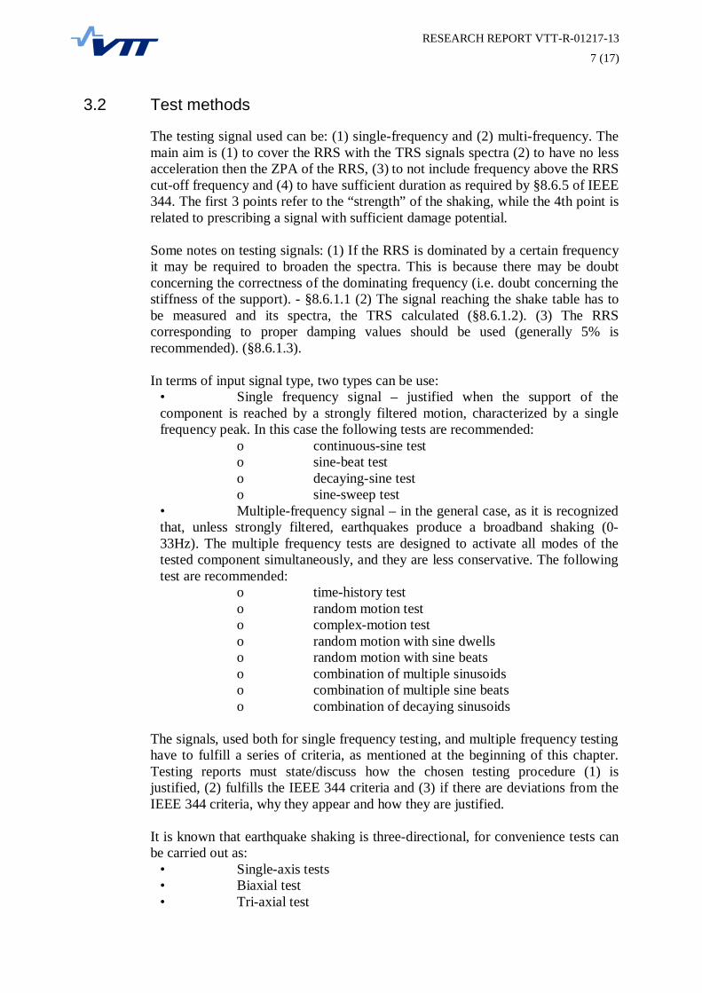
The testing signal used can be: (1) single-frequency and (2) multi-frequency. Themain aim is (1) to cover the RRS with the TRS signals spectra (2) to have no lessacceleration then the ZPA of the RRS, (3) to not include frequency above the RRScut-off frequency and (4) to have sufficient duration as required by §8.6.5 of IEEE344. The first 3 points refer to the “strength” of the shaking, while the 4th point isrelated to prescribing a signal with sufficient damage potential.
Some notes on testing signals: (1) If the RRS is dominated by a certain frequencyit may be required to broaden the spectra. This is because there may be doubtconcerning the correctness of the dominating frequency (i.e. doubt concerning thestiffness of the support). - §8.6.1.1 (2) The signal reaching the shake table has tobe measured and its spectra, the TRS calculated (§8.6.1.2). (3) The RRScorresponding to proper damping values should be used (generally 5% isrecommended). (§8.6.1.3).
In terms of input signal type, two types can be use:• Single frequency signal – justified when the support of thecomponent is reached by a strongly filtered motion, characterized by a singlefrequency peak. In this case the following tests are recommended:
o continuous-sine testo sine-beat testo decaying-sine testo sine-sweep test
• Multiple-frequency signal – in the general case, as it is recognizedthat, unless strongly filtered, earthquakes produce a broadband shaking (0-33Hz). The multiple frequency tests are designed to activate all modes of thetested component simultaneously, and they are less conservative. The followingtest are recommended:
o time-history testo random motion testo complex-motion testo random motion with sine dwellso random motion with sine beatso combination of multiple sinusoidso combination of multiple sine beatso combination of decaying sinusoids
The signals, used both for single frequency testing, and multiple frequency testinghave to fulfill a series of criteria, as mentioned at the beginning of this chapter.Testing reports must state/discuss how the chosen testing procedure (1) isjustified, (2) fulfills the IEEE 344 criteria and (3) if there are deviations from theIEEE 344 criteria, why they appear and how they are justified.
It is known that earthquake shaking is three-directional, for convenience tests canbe carried out as:
• Single-axis tests• Biaxial test• Tri-axial test
RESEARCH REPORT VTT-R-01217-13
8 (17)
Single and bi axial test must have a certain level of conservativeness,compensating for the lack of simultaneous shaking in other direction. Themeasures to achieve this level of conservativeness are specified in IEEE 344.
3.3 Extrapolation from similar equipment & multi-cabinetassemblies
Another option is to qualify equipment by reference to (1) already qualifiedequipment which (2) is judged to be similar to the one under consideration. Boththe conditions for “similarity” and the methods for acceptable extrapolation aredefined by IEEE-344 (§9.3).
A special case of qualification is the case when repetitive cabinets are to bequalified. IEEE 344 acknowledges the difficulty to test such assemblies becauseof their size, but warns against qualifying one individual unit and trying toextrapolate the results for the whole assembly. The core argument is thatindividual units do behave differently than whole assemblies because of (1)interaction, (2) torsional effects etc. – therefore, a more sophisticated justificationis needed for the extrapolation from one unit to the whole.
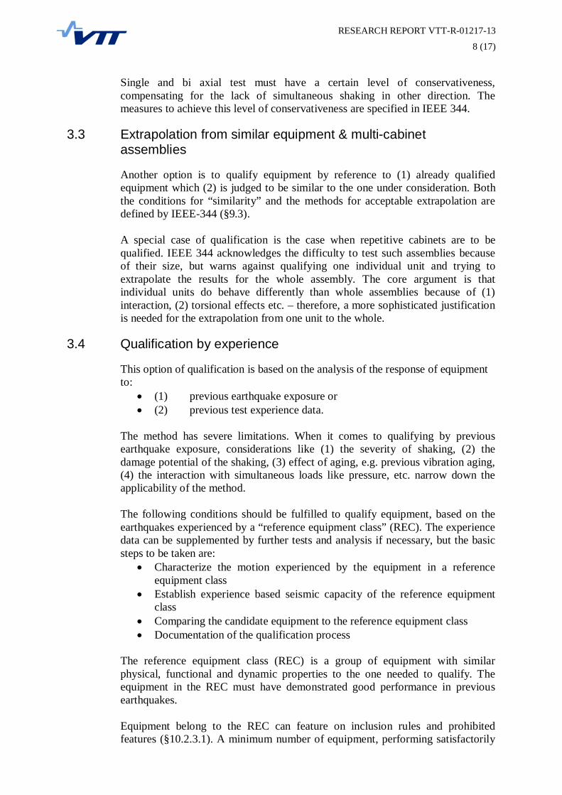
3.4 Qualification by experience
This option of qualification is based on the analysis of the response of equipmentto:
(1) previous earthquake exposure or(2) previous test experience data.
The method has severe limitations. When it comes to qualifying by previousearthquake exposure, considerations like (1) the severity of shaking, (2) thedamage potential of the shaking, (3) effect of aging, e.g. previous vibration aging,(4) the interaction with simultaneous loads like pressure, etc. narrow down theapplicability of the method.
The following conditions should be fulfilled to qualify equipment, based on theearthquakes experienced by a “reference equipment class” (REC). The experiencedata can be supplemented by further tests and analysis if necessary, but the basicsteps to be taken are:
Characterize the motion experienced by the equipment in a referenceequipment classEstablish experience based seismic capacity of the reference equipmentclassComparing the candidate equipment to the reference equipment classDocumentation of the qualification process
The reference equipment class (REC) is a group of equipment with similarphysical, functional and dynamic properties to the one needed to qualify. Theequipment in the REC must have demonstrated good performance in previousearthquakes.
Equipment belong to the REC can feature on inclusion rules and prohibitedfeatures (§10.2.3.1). A minimum number of equipment, performing satisfactorily

RESEARCH REPORT VTT-R-01217-13
9 (17)
in independent circumstances, needs to be available in the REC (§ 10.2.3.2).Independent items need to have (1) different physical characteristics, (2)experience different earthquake load, (3) be in different locations (e.g. inside abuilding) for the same earthquake load, or (4) have different orientation.
The minimum required independent items for a REC are 15 (with penalty of 30%on the loads) and 30 with no penalty.
The accepted load level for qualification for the REC is defined by the earthquakeexperience spectrum, or EES. The EES is the weighted average response spectraexperienced by- equipment. Weighting is done to the number of independentequipment items in each location:
=
Where:SAEES – is the earthquake experience spectrum;Nn – is the number of independent items in reference site nSAn – is the spectra experienced by the independent equipment in reference site n
In order to qualify the candidate equipment, the RRS (required response spectra)must be enveloped by the EES in the frequency range of interests (§10.2.4).Failure to envelope the RRS must be justified. The RRS for typical equipment isin-structure, horizontal, medial centered, 5% damped floor spectra resulting fromthe SSE (safe-shutdown earthquake).
The candidate equipment must be verified to possess the inclusion rules of theREC and exclude the prohibition rules of the REC. The mounting of the candidateequipment must be evaluated in accordance with the qualification requirements(§10.2.4.f), and any significant design changes from the vintage of the equipmentin the REC and the candidate equipment must be assessed if they could reduceseismic capacity.
3.5 Shock testing
IEEE 344 specifically warns against using results from shock test in earthquakequalification, citing the differences in (1) frequency content and (2) load duration.
4 Qualifying equipment according to CEI/IEC 68-3-3
The scope of ICE 68-3-3 is restricted to electro technical equipment (§1), and onlyhas the ambition to guide the verification of the equipment by testing. Thereforeonly equipment size to be placed to a shake table can be considered. Fragilitytesting is also excluded from the focus of IEC 68-3-3.
The equipment qualification can be carried out using the (1) general seismic classor the (2) specific seismic class. General seismic class is to be used when theseismic loads are not known form a study dedicated for the specific equipmentlocation. This is usually not the case in safety related NPP components. Thespecific seismic class provisions are to be used, when the seismic environment has

RESEARCH REPORT VTT-R-01217-13
10 (17)
been defined for the specific equipment location. For the specific seismic class theseismic loads are defined by response spectra or time history.
4.1 Qualification consideration and general procedures
One condition for testing equipment is that service conditions should be replicatedas closely as possible. IEC 68-3-3 classifies qualification to:Criteria 0: subjected to seismic test, experienced no malfunctionCriteria 1: experienced malfunction during test but recovered function post-
shakingCriteria 2: experienced malfunction, required resetting or adjustments to restart,
but became functional without replacement or repair
The mounting of the equipment should be according to IEC 68-2-47 and musttake into account the connections, piping and cables. The “in service” mountingstructure of the equipment should be included in the test.
Vibration of the shake table should be measured to make sure that correct level ofvibration is transmitted to the specimen. Vibration measurements may be takenform the specimen/equipment if they are required for the qualification process, butthey are not part of the test requirement.
Usually, the range of frequencies for testing is 1-35Hz. Deviation from thesevalues should be justified (§5.3).
4.2 Loads for testing of specific seismic class equipment
For the specific seismic class equipment (NPP case), the prefer test waves are:sin sweep for vibration response investigationsin beattime-historycontinuous sine for endurance at fixed frequency
Both the use of multi-frequency and single frequency waves is permitted. Themain condition is that the test response spectrum (TRS) of the wave envelopes therequired response spectrum (RRS), and the strong motion part of the signal isappropriate.
For evaluating seismic risk at the particular site allowance has to be made for afive S1 earthquakes, corresponding to OBE in NPP applications, followed by andS2 earthquake, corresponding to SSE in NPP applications (§13.1.2). Deviation forthis loading protocol must be justified.
In certain cases the S1 loading sequences can be replaced by S2 loading, with thecondition that the equivalency covers the vibration aging effects of the replacedS1 sequences (§13.1.2).
The test waves can be applied as “wave sequences”, with waves spaced at least at2s, in order to avoid superimposing shaking effects from each sequence.

RESEARCH REPORT VTT-R-01217-13
11 (17)
Figure 1. Sequence of five sine beats with five cycle
In case of multi-frequency wave being used as load, it should be ensured that theRRS is enveloped by the TRS (§13.2). In case of using time-history records asloads, the accelerograms may be overlapped with e.g. sine-beat signals, in order toproduce a testing signal with spectra close to the RRS, and ZPA not muchexceeding the target ZPA. The TRS should envelope the RRS in the range offrequencies starting from the resonance frequencies of the equipment up to 35Hz.
Figure 2. Types of response spectrum envelope

RESEARCH REPORT VTT-R-01217-13
12 (17)
Besides multi-frequency testing described above, single frequency testing i.e. sin-sweep test, sine-beat tests, continuous-sine test are also permitted (§13.2).
4.3 Testing conditions and methods
The difficulty of defining loading signal for qualification test is highlighted withregards to aspects like:
Weather the equipment is used in a particular location, or qualification isrequired for a generic location;How much broadening of the RRS is required because of uncertaintiesrelated to e.g. natural frequencies of the building. The broadened RRS iscalled the broad band RRS (Figure 3);The multi-directionality of the shaking;Simulating operating conditions for complex equipment assemblies;
Figure 3. Typical envelope response spectrum
Vibration response investigation is normally carried out using a single directionsinusoidal excitation logarithmic sweep cycle in the range of 1-35Hz (§14.2). Theexcitation amplitude is normally 2m/s2 or 1m/s2 in cases when sharp resonancepeeks are expected.
RESEARCH REPORT VTT-R-01217-13
13 (17)
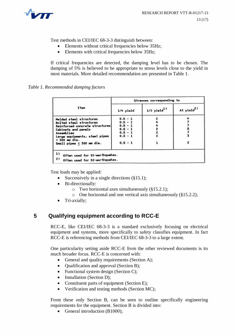
Test methods in CEI/IEC 68-3-3 distinguish between:Elements without critical frequencies below 35Hz;Elements with critical frequencies below 35Hz;
If critical frequencies are detected, the damping level has to be chosen. Thedamping of 5% is believed to be appropriate to stress levels close to the yield inmost materials. More detailed recommendation are presented in Table 1.
Table 1. Recommended damping factors
Test loads may be applied:Successively in a single directions (§15.1);Bi-directionally:
o Two horizontal axes simultaneously (§15.2.1);o One horizontal and one vertical axis simultaneously (§15.2.2);
Tri-axially;
5 Qualifying equipment according to RCC-E
RCC-E, like CEI/IEC 68-3-3 is a standard exclusively focusing on electricalequipment and systems, more specifically to safety classifies equipment. In factRCC-E is referencing methods from CEI/IEC 68-3-3 to a large extent.
One particularity setting aside RCC-E from the other reviewed documents is itsmuch broader focus. RCC-E is concerned with:
General and quality requirements (Section A);Qualification and approval (Section B);Functional system design (Section C);Installation (Section D);Constituent parts of equipment (Section E);Verification and testing methods (Section MC);
From these only Section B, can be seen to outline specifically engineeringrequirements for the equipment. Section B is divided into:
General introduction (B1000);

RESEARCH REPORT VTT-R-01217-13
14 (17)
Basic rules governing the qualification procedure (B2000);Qualification procedure for normal ambient operating conditions (B3000);Qualification procedure K3 (B4000);Qualification procedure K2 (B5000);Qualification procedure K1 (B6000);Qualification procedure for severe accident condition (B7000);
From the above segment only B4000-B6000 is strictly dedicated to methods ofseismic qualification.
5.1 Qualification procedure K3
The procedure is meant to ensure that equipment located outside of thecontainment is capable to perform its specific functions under normal ambient andunder seismic loading.
5.1.1 Testing procedures
The aim of the testing is to verify the performance of equipment for S2 levelearthquake loads, corresponding to SSE earthquakes. The verification can becarried out by (1) testing (2) analysis or (3) combined testing and analysis. Whentesting is used, the accelerogram corresponding to the SSE should be applied tothe anchoring points of the equipment.
Aging of equipment can be taken into account by testing for earthquake the sameequipment as tested in B3000 (qualification procedure for normal ambientoperating conditions), or by showing that the normal ambient aging mechanismshave no effect on seismic performance.
The acceptable test methods include:Single axis sine-beat or sine-sweep test;Single-axis time history tests;Two-axis time history tests;
CEI/IEC 68-3-3 is specifically referenced for limitations and specific measures ofimplementation for these test types.
5.1.2 Details of implementation
In case of single-axis time history and two-axis time history test the followingspecific measures are imposed:
Minimum duration of strong signal portion (25% of maximum value andabove) 10s;Total signal duration 20s;At least:
o 6 (positive or negative) peaks exceeding 70% of maximum ZPAfor single axis;
o 8 (positive or negative) peaks exceeding 70% of maximum ZPAfor two axis;

RESEARCH REPORT VTT-R-01217-13
15 (17)
Il all cases the S2/SSE level test has to be preceded by 5 S1/OBE level seismictests. If no other data is available, the electrical equipment should be qualified forall floor spectra where electrical equipment may be installed. The recommendedgeneral RRS spectral shapes are presented in Figure 4.
a)
b)Figure 4. General purpose (a) horizontal and (b) vertical RRS spectra
5.2 Qualification procedure K2
K2 is the seismic qualification procedure dedicated to electrical equipment insidethe containment. The aim is to show that equipment is capable to perform itsspecific functions under ambient and seismic conditions.

RESEARCH REPORT VTT-R-01217-13
16 (17)
The main difference with K3 refers to the treatment of radiation aging affectingthe equipment.
5.3 Qualification procedure K1
K1 is dedicated to equipment insulated inside of the containment, with thepurpose of showing that they are capable to perform their functions under seismicloading and under normal, accidental and post accidental ambient conditions.
Besides the seismic qualification measures for K1 equipment, therecommendations of NF M64-001 “Procedure For Qualification Of ElectricEquipment Installed In Containments For Pressurized Water Reactors Subject ToAccident Conditions” have to be followed. The supplementary measures refer tospectral shapes and OBE/SSE loading specifications:
Table 2. NF M64-001 supplementary recommendations for K1 equipment qualification
6 Conclusions
The following preliminary conclusions and recommendations can be formulated:Equipment qualification is characterized by very diversified regulatorybackground. Fundamentally, these regulations are based in soundengineering principles, so they should not result in assessment leading tovery different level of safety;It is important to closely assess the application area of the standard usedfor qualification. E.g. two of the standards reviewed here are explosivelydedicated to electrical equipment;It appears to be generally accepted that equipment should be qualified forSSE but with consideration of vibration aging from previous OBE events;It is important (and very challenging!) to account for aging mechanismsthat may affect the seismic performance;Uncertainties of the response in the structural system supporting theequipment should be taken into account by broadening the RRS spectraresulting from structural analysis;

RESEARCH REPORT VTT-R-01217-13
17 (17)
References
[1] ASCE 4-98 – Seismic Analysis of Safety-Related Nuclear Structures and Commentary[2] YVL 2.6 - Maanjaristysten Huomioon Ottaminen Ydinvoimalaitoksissa. STUK, 2001.[3] RCC-E; Design and construction rules for Electrical Components of nuclear islands;
AFCEN 2005 (ISBN 2-913638-17-1)[4] Seismic Design and Qualification for Nuclear Power Plants. Vienna: IAEA, 2003.[5] IEEE Recommended Practice for Seismic Qualification of Class 1E Equipment for
Nuclear Power Generating Stations, IEEE Std 344-2004;[6] IEEE Standard for Qualifying Class 1E Equipment for Nuclear Power Generating
Stations, IEEE Std 323-2003;[7] EPRI; Methodology for Developing Seismic Fragilities; TR-103959, Final report 1994[8] IEC 60068-3-3 Environmental testing - Part 3: Guidance. Seismic test methods for
equipment[9] IEC 60980: Recommended Practices for Seismic Qualification of Electrical
Equipment of the Safety System for Nuclear Generating Stations