CODE OF PRACTICE THREE - ELEXON · Code of Practice Three Issue 5 ... 5 1/9/98 3.00 Harmonisation...
41
Code of Practice Three Issue 5 (v 3.00) Balancing and Settlement Code Page 1 of 41 Code Effective Date CODE OF PRACTICE THREE CODE OF PRACTICE FOR THE METERING OF CIRCUITS WITH A RATED CAPACITY NOT EXCEEDING 10MVA FOR SETTLEMENT PURPOSES. Issue 5 Version 3.00 DATE Code Effective Date
Transcript of CODE OF PRACTICE THREE - ELEXON · Code of Practice Three Issue 5 ... 5 1/9/98 3.00 Harmonisation...

Code of Practice Three Issue 5 (v 3.00)
Balancing and Settlement Code Page 1 of 41 Code Effective Date
CODE OF PRACTICE THREE
CODE OF PRACTICE FOR THE METERING OF CIRCUITS
WITH A RATED CAPACITY NOT EXCEEDING 10MVA
FOR SETTLEMENT PURPOSES.
Issue 5
Version 3.00
DATE Code Effective Date

Code of Practice Three Issue 5 (v 3.00)
Balancing and Settlement Code Page 2 of 41 Code Effective Date
Code of Practice Three
CODE OF PRACTICE FOR THE METERING OF CIRCUITS WITH A RATED
CAPACITY NOT EXCEEDING 10MVA FOR SETTLEMENT PURPOSES.
1. Reference is made to the Balancing and Settlement Code for the Electricity Industry in
England and Wales dated Code Effective Date, and, in particular, to the definition of
"Code of Practice" in Annex X-1 thereof.
2. This Code of Practice shall apply to Metering Systems comprising Metering Equipment
that are subject to the requirements of Section L of the Balancing and Settlement Code.
3. This Code of Practice has been approved by the Panel.
_________________________________
For and on behalf of the Panel.

Code of Practice Three Issue 5 (v 3.00)
Balancing and Settlement Code Page 3 of 41 Code Effective Date
AMENDMENT RECORD
ISSUE DATE VERSION CHANGES AUTHOR APPROVED
Draft 18/3/93 0.03 Recommended to PEC MSC
1 15/4/93 1.00 Endorsed by PEC COP WG
19/4/95 1.01 Draft COPWG
14/6/95 1.02 Draft COPWG
22/6/95 1.03 Draft for MDC COP WG
27/7/95 1.04 Draft following
comments by MDC
COP WG
Approved by
MDC 7/9/95
2 8/9/95 2.00 Implementation date
agreed by MDC
COP WG
3 1/5/97 2.03 Amendments for 100kW
Take-on
1998
Programme
Approved by
MDC 1/5/97
1/9/97 2.05 Amended following
review by Expert Group
and internally.
1998
Programme
(C A Team)
25/3/98 2.06 Draft for MDC CoPSRP
20/4/98 2.07 Post MDC revisions and
CoPSRP on 17/4/98
CoPSRP
4 1998
Operational
Date
2.05 Amended following
review by Expert Group
and internally.
1998
Programme
(CA Team)

Code of Practice Three Issue 5 (v 3.00)
Balancing and Settlement Code Page 4 of 41 Code Effective Date
ISSUE DATE VERSION CHANGES AUTHOR APPROVED
5 1/9/98 3.00 Harmonisation of Codes
of Practice
COPSRP Approved by
MDC 4/6/98
5 Code
Effective
Date1
3.00 Re-badging of Code of
Practice Three for the
implementation of the
Balancing and Settlement
Code
BSCCo Panel
16/11/00
(Paper
07/003)
1 “Code Effective Date” means the date of the Framework Agreement.

Code of Practice Three Issue 5 (v 3.00)
Balancing and Settlement Code Page 5 of 41 Code Effective Date
CODE OF PRACTICE FOR THE METERING OF CIRCUITS WITH A RATED
CAPACITY NOT EXCEEDING 10MVA FOR SETTLEMENT PURPOSES.
1. SCOPE ......................................................................................................................................................... 8
2. REFERENCES ............................................................................................................................................ 9
3. DEFINITIONS AND INTERPRETATIONS .......................................................................................... 10
3.1 ACTIVE ENERGY * ................................................................................................................................... 10
3.2 ACTIVE POWER *..................................................................................................................................... 10
3.3 ACTUAL METERING POINT ‡ ................................................................................................................... 10
3.4 APPARENT ENERGY ‡ .............................................................................................................................. 10
3.5 APPARENT POWER ‡ ................................................................................................................................ 10
3.6 CTN ‡ ..................................................................................................................................................... 11
3.7 CVA CUSTOMER † .................................................................................................................................. 11
3.8 DE-ENERGISED ‡ ..................................................................................................................................... 11
3.9 DEFINED METERING POINT ‡ ................................................................................................................... 11
3.10 DEMAND PERIOD ‡ ............................................................................................................................. 11
3.11 DEMAND VALUES ‡ ............................................................................................................................ 11
3.12 ELECTRICITY *.................................................................................................................................... 11
3.13 EXPORT † ........................................................................................................................................... 11
3.14 IMPORT † ............................................................................................................................................ 12
3.15 INTERROGATION UNIT ‡ ..................................................................................................................... 12
3.16 MAXIMUM DEMAND † ........................................................................................................................ 12
3.17 METER * ............................................................................................................................................. 12
3.18 METERING EQUIPMENT * .................................................................................................................... 12
3.19 METER REGISTER ‡ ............................................................................................................................ 12
3.20 METERING SYSTEM * ......................................................................................................................... 12
3.21 OUTSTATION * .................................................................................................................................... 12
3.22 OUTSTATION SYSTEM ‡ ...................................................................................................................... 13
3.23 PASSWORD ‡ ...................................................................................................................................... 13
3.24 PSTN ‡ .............................................................................................................................................. 13
3.25 RATED MEASURING CURRENT ‡ ......................................................................................................... 13
3.26 REACTIVE ENERGY * .......................................................................................................................... 13
3.27 REACTIVE POWER * ............................................................................................................................ 13
3.28 REGISTRANT ....................................................................................................................................... 13
3.29 SETTLEMENT INSTATION ‡ .................................................................................................................. 13
3.30 SVA CUSTOMER ................................................................................................................................ 14
3.31 UTC ‡ ................................................................................................................................................ 14
4. MEASUREMENT CRITERIA ................................................................................................................ 15
4.1 MEASURED QUANTITIES AND DEMAND VALUES ..................................................................................... 15
4.1.1 Measured Quantities ..................................................................................................................... 15
4.1.2 Demand Values ............................................................................................................................. 15
4.2 ACCURACY REQUIREMENTS .................................................................................................................... 16
4.2.1 Overall Accuracy .......................................................................................................................... 16
4.2.2 Compensation for Measurement Transformer Error .................................................................... 17
4.2.3 Compensation for Power Transformer and Line Losses ............................................................... 17
5. METERING EQUIPMENT CRITERIA ................................................................................................ 19
5.1 MEASUREMENT TRANSFORMERS ............................................................................................................ 19
5.1.1 Current Transformers ................................................................................................................... 19
5.1.2 Voltage Transformers ................................................................................................................... 20
5.1.3 Measurement Transformers Installed on Existing Circuits .......................................................... 20
Code of Practice Three Issue 5 (v 3.00)
Balancing and Settlement Code Page 6 of 41 Code Effective Date
5.2 FUSING AND TESTING FACILITIES ............................................................................................................ 21
5.3 METERS .................................................................................................................................................. 21
5.4 DISPLAYS AND FACILITIES FOR REGISTRANT OR SUPPLIER INFORMATION ............................................... 22
5.4.1 Displays ........................................................................................................................................ 22
5.4.2 Facilities ....................................................................................................................................... 23
5.5 OUTSTATION ........................................................................................................................................... 24
5.5.1 Data Storage ................................................................................................................................. 24
5.5.2 Time Keeping ................................................................................................................................ 25
5.5.3 Monitoring Facilities .................................................................................................................... 26
5.6 COMMUNICATIONS .................................................................................................................................. 26
5.6.1 Local Interrogation ....................................................................................................................... 28
5.6.2 Remote Interrogation .................................................................................................................... 28
5.7 APPROPRIATE SEALS ............................................................................................................................... 29
6. ASSOCIATED FACILITIES ................................................................................................................... 30
6.1 INTERROGATION UNIT ............................................................................................................................. 30
6.2 ADDITIONAL FEATURES ........................................................................................................................... 30
7. ACCESS TO DATA .................................................................................................................................. 31
APPENDIX A DEFINED METERING POINTS ......................................................................................... 32
APPENDIX B LABELLING OF METERS FOR IMPORT AND EXPORT ............................................ 34
APPENDIX C TYPICAL TESTING FACILITIES AND FUSING ARRANGEMENTS ......................... 37
APPENDIX D PASSWORDS ......................................................................................................................... 38
APPENDIX E OPTIONS FOR ENSURING METERS AND DISPLAYS CAN BE READ AND
REMOTELY INTERROGATED ..................................................................................................................... 39
APPENDIX F GENERIC DISPENSATIONS .............................................................................................. 41

Code of Practice Three Issue 5 (v 3.00)
Balancing and Settlement Code Page 7 of 41 Code Effective Date
FOREWORD
This Code of Practice defines the minimum requirements for the Metering Equipment
required for the measurement and recording of electricity transfers at Defined Metering Points
where the rated circuit capacity does not exceed 10MVA.
For the purpose of this Code of Practice the rated circuit capacity in MVA shall be
determined by the lowest rated primary plant (e.g. transformer rating, line rating, etc) of the
circuit. The Metering Equipment provision and accuracy requirements shall anticipate any
future up-rating consistent with the installed primary plant. The primary plant maximum
continuous ratings shall be used in this assessment.
BSCCo shall retain copies of, inter alia, the Code of Practice together with copies of all
documents referred to in them, in accordance with the provisions of the Balancing and
Settlement Code (the Code).

Code of Practice Three Issue 5 (v 3.00)
Balancing and Settlement Code Page 8 of 41 Code Effective Date
1. SCOPE
This Code of Practice states the practices that shall be employed, and the facilities that shall
be provided for the measurement and recording of the quantities required for Settlement
purposes on each circuit where the rated capacity does not exceed 10MVA.
It derives force from the Code, and in particular the metering provisions (Section L), to which
reference should be made. It should also be read in conjunction with the BSC Procedures.
This Code of Practice does not contain the calibration, testing and commissioning
requirements for Metering Equipment used for Settlement purposes. These requirements are
detailed in Code of Practice Four - "Code of Practice for Calibration, Testing and
Commissioning Requirements for Metering Equipment for Settlement Purposes".
Metering Dispensations from the requirements of this Code of Practice may be sought in
accordance with the Code and the BSC Procedure BSCP32.
In the event of an inconsistency between the provisions of this Code of Practice and the Code,
the provisions of the Code shall prevail.
Code of Practice Three Issue 5 (v 3.00)
Balancing and Settlement Code Page 9 of 41 Code Effective Date
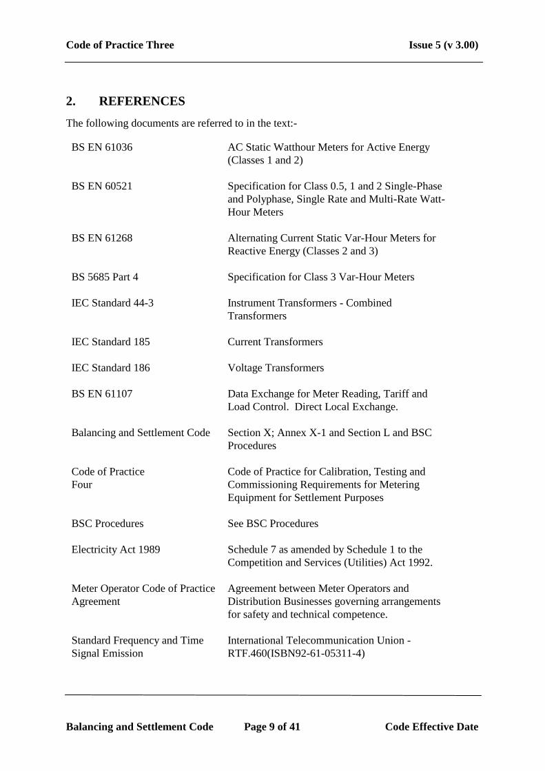
2. REFERENCES
The following documents are referred to in the text:-
BS EN 61036 AC Static Watthour Meters for Active Energy
(Classes 1 and 2)
BS EN 60521 Specification for Class 0.5, 1 and 2 Single-Phase
and Polyphase, Single Rate and Multi-Rate Watt-
Hour Meters
BS EN 61268
Alternating Current Static Var-Hour Meters for
Reactive Energy (Classes 2 and 3)
BS 5685 Part 4 Specification for Class 3 Var-Hour Meters
IEC Standard 44-3 Instrument Transformers - Combined
Transformers
IEC Standard 185 Current Transformers
IEC Standard 186 Voltage Transformers
BS EN 61107 Data Exchange for Meter Reading, Tariff and
Load Control. Direct Local Exchange.
Balancing and Settlement Code Section X; Annex X-1 and Section L and BSC
Procedures
Code of Practice
Four
Code of Practice for Calibration, Testing and
Commissioning Requirements for Metering
Equipment for Settlement Purposes
BSC Procedures
See BSC Procedures
Electricity Act 1989 Schedule 7 as amended by Schedule 1 to the
Competition and Services (Utilities) Act 1992.
Meter Operator Code of Practice
Agreement
Agreement between Meter Operators and
Distribution Businesses governing arrangements
for safety and technical competence.
Standard Frequency and Time
Signal Emission
International Telecommunication Union -
RTF.460(ISBN92-61-05311-4)

Code of Practice Three Issue 5 (v 3.00)
Balancing and Settlement Code Page 10 of 41 Code Effective Date
3. DEFINITIONS AND INTERPRETATIONS
Save as otherwise expressly provided herein, words and expressions used in this Code of
Practice shall have the meanings attributed to them in the Code and are included for the
purpose of clarification.
Note: * indicates definitions in the Code.
Note: † indicates definitions which supplement or complement those in the Code.
Note: ‡ indicates definitions specific to this Code of Practice.
3.1 Active Energy *
Active Energy means the electrical energy produced, flowing or supplied by an
electric circuit during a time interval, being the integral with respect to time of the
instantaneous Active Power, measured in units of watt-hours or standard multiples
thereof;
3.2 Active Power *
Active Power means the product of voltage and the in-phase component of alternating
current measured in units of watts and standard multiples thereof, that is:
1,000 Watts = 1 kW
1,000 kW = 1 MW
3.3 Actual Metering Point ‡
Actual Metering Point means the physical location at which electricity is metered.
3.4 Apparent Energy ‡
Apparent Energy means the integral with respect to time of the Apparent Power.
3.5 Apparent Power ‡
Apparent Power means the product of voltage and current measured in units of volt-
amperes and standard multiples thereof, that is:-
1,000 VA = 1 kVA
1,000 kVA = 1 MVA

Code of Practice Three Issue 5 (v 3.00)
Balancing and Settlement Code Page 11 of 41 Code Effective Date
3.6 CTN ‡
CTN means the Electricity Supply Industry (ESI) corporate telephone network.
3.7 CVA Customer †
CVA Customer means any customer, receiving electricity directly from the
Transmission System, irrespective of from whom it is supplied.
3.8 De-Energised ‡
De-Energised means the temporary removal of the supply at a Defined Metering Point
(e.g. the main circuit connections to the Public Distribution System Operators network
are still made) such that all or part of the Metering Equipment is considered to be
temporarily "inactive" for the purposes of Settlement. e.g. unoccupied premises where
the incoming switchgear has been opened or the cut-out fuse(s) removed.
3.9 Defined Metering Point ‡
Defined Metering Point means the physical location at which the overall accuracy
requirements as stated in this Code of Practice are to be met. The Defined Metering
Points are identified in Appendix A and relate to Boundary Points and System
Connection Points.
3.10 Demand Period ‡
Demand Period means the period over which Active Energy, Reactive Energy or
Apparent Energy are integrated to produce stored energy values. For Settlement
purposes, unless the context requires otherwise, each Demand Period shall be of 30
minutes duration, one of which shall finish at 24:00 hours.
3.11 Demand Values ‡
Demand Values means, expressed in kW, kvar or kVA, twice the value of kWh, kvarh
or kVAh recorded during any Demand Period. The Demand Values are half hour
demands and these are identified by the time of the end of the Demand Period.
3.12 Electricity *
electricity means Active Energy and Reactive Energy.
3.13 Export †
Export means, for the purposes of this Code of Practice, an electricity flow as
indicated in Figure 1 of Appendix B.

Code of Practice Three Issue 5 (v 3.00)
Balancing and Settlement Code Page 12 of 41 Code Effective Date
3.14 Import †
Import means, for the purposes of this Code of Practice, an electricity flow as
indicated in Figure 1 of Appendix B.
3.15 Interrogation Unit ‡
Interrogation Unit means a Hand Held Unit "HHU" (also known as Local
Interrogation Unit LIU") or portable computer which can enter Metering Equipment
parameters and extract information from the Metering Equipment and store this for
later retrieval.
3.16 Maximum Demand †
Maximum Demand expressed in kW or kVA means twice the greatest number of kWh
or kVAh recorded during any Demand Period.
3.17 Meter *
Meter means a device for measuring Active Energy and/or Reactive Energy.
3.18 Metering Equipment *
Metering Equipment means Meters, measurement transformers (voltage, current or
combination units), metering protection equipment including alarms, circuitry,
associated Communications Equipment and Outstation and wiring.
3.19 Meter Register ‡
Meter Register means a device, normally associated with a Meter, from which it is
possible to obtain a reading of the amount of Active Energy, or the amount of
Reactive Energy that has been supplied by a circuit.
3.20 Metering System *
Metering System means particular commissioned Metering Equipment, as defined in
Section X; Annex X-1 of the Balancing and Settlement Code.
3.21 Outstation *
Outstation means equipment which receives and stores data from a Meter(s) for the
purpose, inter-alia, of transfer of that metering data to the Central Data Collector
Agent (CDCA) or Data Collector as the case may be, and which may perform some
processing before such transfer and may be in one or more separate units or may be
integral with the Meter.

Code of Practice Three Issue 5 (v 3.00)
Balancing and Settlement Code Page 13 of 41 Code Effective Date
3.22 Outstation System ‡
Outstation System means one or more Outstations linked to a single communication
line.
3.23 Password ‡
Password means a string of characters of length no less than six characters and no
more than twelve characters, where each character is a case insensitive alpha character
(A to Z) or a digit (0 to 9) or the underscore character (_). Passwords must have a
minimum of 2,000,000,000 combinations, for example six characters if composed of
any alphanumeric characters or eight characters if composed only of hexadecimal
characters (0 to F).
3.24 PSTN ‡
PSTN means the public switched telephone network.
3.25 Rated Measuring Current ‡
Rated Measuring Current means the rated primary current of the current transformers
in primary plant used for the purposes of measurement.
3.26 Reactive Energy *
Reactive Energy means the integral with respect to time of the Reactive Power.
3.27 Reactive Power *
Reactive Power means the product of voltage and current and the sine of the phase
angle between them, measured in units of voltamperes reactive and standard multiples
thereof.
3.28 Registrant
Registrant means in relation to a Metering System, the person for the time being
registered in CMRS or (as the case may be) SMRS in respect of that Metering System
pursuant to Section K of the Balancing and Settlement Code.
3.29 Settlement Instation ‡
Settlement Instation means a computer based system which collects or receives data
on a routine basis from selected Outstation by the Central Data Collector or (as the
case may be) a relevant Data Collector.

Code of Practice Three Issue 5 (v 3.00)
Balancing and Settlement Code Page 14 of 41 Code Effective Date
3.30 SVA Customer
means a person to whom electrical power is provided, whether or not that person is
the provider of that electrical power; and where that electrical power is measured by a
SVA Metering System.
3.31 UTC ‡
UTC means Co-ordinated Universal Time which bears the same meaning as in the
document Standard Frequency and Time Signal Emission, International
Telecommunication Union - RTF.460(ISBN92-61-05311-4) (colloquially referred to
as Rugby Time).

Code of Practice Three Issue 5 (v 3.00)
Balancing and Settlement Code Page 15 of 41 Code Effective Date
4. MEASUREMENT CRITERIA
4.1 Measured Quantities and Demand Values
4.1.1 Measured Quantities
For each separate circuit the following energy measurements are required for
Settlement purposes:-
(i) Import kWh
(ii) Export kWh
(iii) Import kvarh
(iv) Export kvarh
4.1.2 Demand Values
For each Demand Period for each circuit the following Demand Values shall be
provided:-
(i) Import kW
(ii) Export kW
(iii) Import kvar
(iv) Export kvar
* Import and/or Export metering need only be installed where a Party requires
this measurement to meet system or plant conditions.
Where Import and Export metering is installed gross Import and gross Export Active
Energy shall be recorded separately for Settlements.
For multiple circuit connections between Parties the configuration of the Metering
Equipment shall be agreed in advance with the Panel.
}*
}*

Code of Practice Three Issue 5 (v 3.00)
Balancing and Settlement Code Page 16 of 41 Code Effective Date
4.2 Accuracy Requirements
4.2.1 Overall Accuracy
The overall accuracy of the energy measurements at or referred to the Defined
Metering Point shall at all times be within the limits of error as shown:-
(i) Active Energy
CONDITION LIMIT OF ERRORS AT STATED
SYSTEM POWER FACTOR
Current expressed as a percentage
of Rated Measuring Current
Power Factor
Limits of Error
120% to 10% inclusive
Below 10% to 5%
120% to 10% inclusive
1
1
0.5 lag and 0.8 lead
± 1.5%
± 2.0%
± 2.5%

Code of Practice Three Issue 5 (v 3.00)
Balancing and Settlement Code Page 17 of 41 Code Effective Date
(ii) Reactive Energy
CONDITION LIMIT OF ERRORS AT STATED
SYSTEM POWER FACTOR
Current expressed as a percentage
of Rated Measuring Current
Power Factor
Limits of Error
120% to 10% inclusive
120% to 20% inclusive
Zero
0.866 lag and 0.866
lead
± 4.0%
± 5.0%
These limits of error for both (i) and (ii) above shall apply at the Reference
Conditions defined in the appropriate Meter specification.
Evidence to verify that these overall accuracy requirements are met shall be
available for inspection by either the Panel or the Technical Assurance Agent.
4.2.2 Compensation for Measurement Transformer Error
To achieve the overall accuracy requirements it may be necessary to compensate
Meters for the errors of the measurement transformers and the associated leads to the
Meters. Values of the compensation shall be recorded and evidence to justify the
compensation criteria, including wherever possible test certificates, shall be available
for inspection by either the Panel or the Technical Assurance Agent.
4.2.3 Compensation for Power Transformer and Line Losses
Where the Actual Metering Point and the Defined Metering Point do not coincide a
Metering Dispensation shall be applied for and, where necessary, compensation for
power transformer and/or line losses shall be provided to meet the overall accuracy at
the Defined Metering Point.
The compensation may be achieved in the Metering Equipment and in this event the
applied values shall be recorded. Supporting evidence to justify the compensation
criteria shall be available for inspection by either the Panel or the Technical Assurance
Agent.

Code of Practice Three Issue 5 (v 3.00)
Balancing and Settlement Code Page 18 of 41 Code Effective Date
Alternatively, the compensation may be applied in the software of the relevant data
aggregation system used for Settlement purposes. In this event the factors shall be
passed to the appropriate agency and evidence to justify the compensation criteria
shall be made available for inspection by either the Panel or the Technical Assurance
Agent.

Code of Practice Three Issue 5 (v 3.00)
Balancing and Settlement Code Page 19 of 41 Code Effective Date
5. METERING EQUIPMENT CRITERIA
Although for clarity this Code of Practice identifies separate items of equipment, nothing in it
prevents such items being combined to perform the same task provided the requirements of
this Code of Practice are met.
Metering Equipment other than outdoor measurement transformers, shall be accommodated
in a clean and dry environment.
For each circuit, other than one which is permanently disconnected, the voltage supply to any
Meters, Displays and Outstations shall be connected such that it is normally energised to
facilitate reading of the Meter Register(s) and Local and Remote Interrogation of the
Outstation. (see Appendix E).
Where an Outstation is storing data for more than one circuit and the Outstation power supply
is from these circuits then a voltage selection relay scheme using each circuit involved shall
be provided.
5.1 Measurement Transformers
The terms "current transformer" and "voltage transformer" used below in 5.1.1 and
5.1.2 do not preclude the use of other measuring techniques with a performance equal
to that specified for such measurement transformers.
For each circuit current transformers (CT) and voltage transformers (VT) shall meet
the requirements set out in clauses 5.1.1 and 5.1.2.
Additionally, where a combined unit measurement transformer (VT & CT) is
provided the 'Tests for Accuracy' as covered in clause 8 of IEC Standard 44-3
covering mutual influence effects shall be met.
5.1.1 Current Transformers
One set of current transformers in accordance with IEC Standard 185 and with a
minimum standard of accuracy to Class 0.5 shall be provided per circuit. Preferably
the current transformers shall be dedicated for Settlement purposes, but the CTs may
be used for other purposes provided the overall accuracy requirements in clause 4.2.1
are met and evidence of the value of the additional burden is available for inspection
by either the Panel or the Technical Assurance Agent.
The additional burden shall not be modified without prior notification to the Panel,
and evidence of the value of the modified additional burden shall be available for
inspection by either the Panel or the Technical Assurance Agent.
CT test certificates showing errors at the overall working burden or at burdens which
enable the working burden errors to be calculated shall be available for inspection by
either the Panel or the Technical Assurance Agent.

Code of Practice Three Issue 5 (v 3.00)
Balancing and Settlement Code Page 20 of 41 Code Effective Date
The total burden on each current transformer shall not exceed the rated burden of such
CT.
5.1.2 Voltage Transformers
A single voltage transformer secondary winding in accordance with IEC Standard
186 and with a minimum standard of accuracy to Class 1 shall be provided for the
main and check metering of a circuit. The voltage transformer secondary winding may
be used for other purposes provided the overall accuracy requirements in clause 4.2.1
are met and evidence of the value of the additional burden is available for inspection
by either the Panel or the Technical Assurance Agent.
The additional burden shall not be modified without prior notification to the Panel,
and evidence of the value of the modified additional burden shall be available for
inspection by either the Panel or the Technical Assurance Agent.
A VT test certificate(s) showing errors at the overall working burden(s) or at burdens
which enable the working burden errors to be calculated shall be available for
inspection by either the Panel or the Technical Assurance Agent.
The total burden on each secondary winding of a VT shall not exceed the rated burden
of such secondary winding.
The VT supplies shall be fused as close as practicable to the VT, with a set of
isolating links, suitably identified, provided locally to the Metering Equipment.
5.1.3 Measurement Transformers Installed on Existing Circuits
Where circuits, other than those newly installed, are to be metered to this Code of
Practice and where the installed measurement transformers do not comply with the
class accuracies specified in clauses 5.1.1 & 5.1.2, then such measurement
transformers may be used providing the following requirements and those in clause
4.2.1 are met:-
(i) Where subsequently a significant alteration to the primary plant (e.g. a
switchgear change) is carried out, new measurement transformers as detailed
in clauses 5.1.1 and 5.1.2, shall be provided.
(ii) In all other respects the requirements of clauses 5.1.1 and 5.1.2 are met, except
that where test certificates are not available other documentary evidence as
referred to in clause 4.2.2 shall be available.

Code of Practice Three Issue 5 (v 3.00)
Balancing and Settlement Code Page 21 of 41 Code Effective Date
5.2 Fusing and Testing Facilities
Testing facilities shall be provided close by the Meters of each circuit, which enables
such Meters to be routinely tested and/or changed safely with the circuit energised.
(see Appendix C)
Separate fusing shall be provided locally for:-
(i) the main Meter
(ii) the check Meter
(iii) any other Settlement Metering Equipment burden
(iv) any other Equipment burden e.g. non-Pool Meters, protection, etc.
Local fusing shall discriminate with the source fusing.
A typical arrangement is illustrated in Appendix C.
Where Current Transformers are used on low voltage installations, the voltage supply
to the Metering Equipment shall be fused as close as practicable to the point of that
supply with a set of isolating links, suitably identified, provided locally to the
Metering Equipment. If that point of supply is close to the Metering Equipment, then
the isolating links may be omitted.
5.3 Meters
The Meters may be either static or induction disc types.
For each circuit main and check Active Energy Meters shall be supplied. These
Meters shall meet the requirements of either BS EN 61036 Class 1 or BS EN 60521
Class 1.
Active Energy Meters provided for the metering of supplies to customers shall be in
accordance with Schedule 7 of the Electricity Act 1989.
For each circuit, only main Reactive Energy Meter(s) need be supplied. The Reactive
Energy Meters shall meet the requirements of either BS EN 61268 Class 3 or BS 5685
Part 4.
Active Energy Meters shall be configured such that the number of measuring elements
is equal to or one less than the number of primary system conductors. These include
the neutral conductor, and/or the earth conductor where system configurations enable
the flow of zero sequence energy.

Code of Practice Three Issue 5 (v 3.00)
Balancing and Settlement Code Page 22 of 41 Code Effective Date
All Meters supplied via measurement transformers shall be set to the actual primary
and secondary ratings of the measurement transformers and the ratios displayed as
follows:-
(i) For Meters separate from the display and/or Outstation the ratios shall be
recorded on the nameplate of the Meter.
(ii) For static Meters combined with the display and/or the Outstation, the ratios
shall be displayed and downloaded during the interrogation process. In
addition, the compensation factor that has been applied for measurement
transformer errors and/or system losses, where this is a constant factor applied
at security level 3 shall be similarly displayed and downloaded.
All Meters shall include a non-volatile Meter Register of cumulative energy for each
measured quantity (see 4.1.1). The Meter Register(s) shall not roll-over more than
once within the normal Meter reading cycle.
Meters which provide data to separate Outstations shall for this purpose provide an
output per measured quantity (see 4.1.1).
For Meters using electronic displays due account shall be taken of the obligations of
the Central Data Collector Agent (CDCA) or other Data Collectors to obtain Meter
readings, even when the circuit is de-energised.
All Meters shall be labelled or otherwise be readily identifiable with respect to their
associated circuit(s), and in accordance with Appendix B.
5.4 Displays and Facilities for Registrant or Supplier Information
5.4.1 Displays
a) Mandatory Displays
The Metering Equipment shall display the following primary information (not
necessarily simultaneously):-
(i) measured quantities as per clause 4.1.1;
(ii) current time ("UTC") and date;
(iii) the CT and/or VT ratios that the Meter has been programmed to, where
appropriate (see clause 5.3); and
(iv) the compensation factor that has been applied for measurement transformer
errors and/or system losses, where this is a constant factor applied at security
level 3 (i.e. where the Meter is combined with the display and/or Outstation).

Code of Practice Three Issue 5 (v 3.00)
Balancing and Settlement Code Page 23 of 41 Code Effective Date
b) Display Capabilities
The Metering Equipment shall be capable of enabling the display of the following
information, as specified by the Registrant:-
(i) Maximum Demand ("MD") for kW per programmable charging period, i.e.
monthly or statistical review period;
(ii) Maximum Demand ("MD") for kVA per programmable charging period, i.e.
monthly or statistical review period;
(iii) twice the kWh advance since the commencement of a current Demand Period,
(i.e. "kW rising demand");
(iv) twice the kVAh advance since the commencement of a current Demand
Period, (i.e. "kVA rising demand");
(v) cumulative MD;
(vi) number of MD resets;
(vii) multi-rate display sequence as specified by the Registrant, with a minimum of
8 rates selectable over the calendar year; and
(viii) indication of reverse running for Active Energy, where appropriate.
MD shall be resettable at midnight of the last day of a charging period and for part
chargeable period demands. If a manual reset button is provided then this shall be
sealable.
5.4.2 Facilities
The Metering Equipment shall be capable of providing the following information
locally to the Customer or Registrant for Stage 1 Metering Equipment; or to the
Customer or Supplier for Stage 2 Metering Equipment, configured to their
requirements taking account of the measured quantities (see clause 4.1.1):-
(i) impulsing for Import kWh , Export kWh, Import kvarh, Export kvarh and
kVAh -all to be voltage free contacts with a pulse rate at full load of between
0.1 and 2 pulses per second with a nominal duration of 80mS per pulse; and
(ii) a 30 minute reset pulse, within a tolerance of +/- 0.1% of the Demand Period
from voltage free contacts with a minimum duration of 0.5 seconds and a
maximum duration of 10 seconds.

Code of Practice Three Issue 5 (v 3.00)
Balancing and Settlement Code Page 24 of 41 Code Effective Date
5.5 Outstation
An Outstation System shall be provided which transfers data to and receives data from
a Settlement Instation.
Where a single separate Outstation is provided for storing data for more than one
circuit, the Maximum Aggregated Capacity shall be 100 MVA.
Where more than one separate Outstation is provided, the main and check Meter data
shall be stored in different Outstations.
The Outstation data shall be to a format and protocol approved by the Panel.
The Outstation shall facilitate the metering data to be read by instations other than the
Settlement Instation provided the requirements of clause 7 of this Code of Practice are
satisfied.
For the purpose of transferring stored metering data from the Outstation to the
Settlement Instation, a unique Outstation identification code shall be provided.
Normally, metering data will be collected by the Settlement Instations by a daily
interrogation, but repeat collections of metering data shall be possible throughout the
Outstation data storage period.
If not integral, the Outstation System supply shall either be from a secure supply or
from a measurement VT, with separate fusing for each Outstation.
Where a separate modem associated with the Outstation System is used, then it shall
be provided with a separately fused supply either from a secure supply or from a
measurement VT (see clause 5). Alternatively, line or battery powered modem types
may be used.
5.5.1 Data Storage
Data storage facilities for metering data shall be provided as follows:-
(i) Each Demand Value shall be identifiable to its respective date and time;
(ii) a storage capacity of 48 periods per day for a minimum of 20 days for all
demand values as defined in clause 4.1.2. The stored values shall be integer
multiples of kW and kvar;
(iii) the resolution of the Energy transferred into the demand registers shall be
within ±0.1% (at full load) of the amount of Energy measured by the
associated Meter;
(iv) the value of any energy measured in a Demand Period but not stored in that
Demand Period shall be carried forward to the next Demand Period;

Code of Practice Three Issue 5 (v 3.00)
Balancing and Settlement Code Page 25 of 41 Code Effective Date
(v) where a separate Outstation is used, cumulative register values shall be
provided in the Outstation which shall be set to match and increment with the
Meter Registers;
(vi) in the event of an Outstation supply failure, the Outstation shall protect all data
stored up to the time of the failure, and maintain the time accuracy in
accordance with clause 5.5.2;
(vii) partial Demand Values, those in which an Outstation supply failure and/or
restoration occurs, and zero Demand Values associated with an Outstation
supply failure, shall be marked so that the Settlement Instation can identify
them;
(viii) to cater for continuous supply failures, the clock, calendar and all data shall be
supported for a period of 20 days without an external supply connected;
(ix) any "read" operation shall not delete or alter any stored metered data; and
(x) an Outstation shall provide all of the metered data stored from the
commencement of any specified date upon request by the Settlement
Instation.
5.5.2 Time Keeping
(i) The Outstation time shall be set to Co-ordinated Universal Time Clock (UTC).
No switching between UTC and British Summer Time (BST) shall occur for
Settlement data storage requirements.
(ii) Time synchronisation of the Outstation may be performed remotely by the
Settlement Instation as part of the normal interrogation process or locally by an
Interrogation Unit.
(iii) When time synchronisation occurs the relevant period(s) shall be marked with
an alarm indication, as outlined in clause 5.5.3.
(iv) The overall limits of error for the time keeping allowing for a failure to
communicate with the Outstation for a period of 20 days shall be:-
a) the completion of each Demand Period shall be at a time which
is within ± 20 seconds of UTC; and
b) the duration of each Demand Period shall be within ± 0.1%,
except where time synchronisation has occurred in a Demand
Period.
Code of Practice Three Issue 5 (v 3.00)
Balancing and Settlement Code Page 26 of 41 Code Effective Date
5.5.3 Monitoring Facilities
Monitoring facilities shall be provided for each of the following conditions and shall
be reported, as separate alarm indications, tagged to the relevant Demand Period(s),
via on-line communications and the local Interrogation Unit:-
(i) phase failure of any one or combination of phases;
(ii) Metering Equipment resets caused by other than a supply failure (where
fitted);
(iii) battery monitoring (where battery fitted);
(iv) interrogation port access which changes time and/or date;
(v) where different from (iv), Demand Period(s) which have been truncated or
extended by a time synchronisation;
(vi) interrogation port access which changes data other than time and/or date; and
(vii) reverse running (if fitted).
In addition to (ii), detected errors in Metering Equipment functionality should be
recorded as an event alarm with date and time.
Any alarm indications shall not be cancelled or deleted by the interrogation process
and shall be retained with the data until overwritten. The alarm shall reset
automatically when the abnormal condition has been cleared.
5.6 Communications
Outstation(s) shall provide both local and remote interrogation facilities, from
separate ports.
To prevent unauthorised access to the data in the Metering Equipment a security
scheme, as defined below and in Appendix D, and shall be incorporated for both local
and remote access. Separate security levels shall be provided for the following
activities:-
(i) Level 1 - Password for:-
Read only of the following metering data, which shall be transferable on request
during the interrogation process:-
a) Outstation ID;
b) Demand Values as defined in clause 4.1.2 for main and check Meters;

Code of Practice Three Issue 5 (v 3.00)
Balancing and Settlement Code Page 27 of 41 Code Effective Date
c) cumulative measured quantities as defined in clause 4.1.1 for main and
check Meters;
d) Maximum Demand (MD) for kW or kVA per programmable charging
period i.e. monthly, statistical review period;
e) multi-rate cumulative Active Energy as specified by Registrant;
f) the measurement transformer ratios, where appropriate (see clause 5.3);
g) the measurement transformer error correction factor and/or system loss
factor, where this is a constant factor applied to the entire dynamic
range of the Meter and the Meter is combined with the display and/or
Outstation;
h) alarm indications; and
i) Outstation time and date.
(ii) Level 2 - Password for:-
a) corrections to the time and/or date; and
b) resetting of the MD.
(iii) Level 3 - Password for:-
Programming of:-
a) the Displays and Facilities as defined in clause 5.4;
b) the measurement transformer ratios, as appropriate (see clause 5.3);
c) the measurement transformer error correction and/or system loss factor
where this is a constant factor applied to the entire dynamic range of
the Meter and the Meter is combined with the display and/or
Outstation; and
d) the passwords for levels 1, 2 and 3.
In addition, it shall be possible to read additional information within the Metering
Equipment to enable the programmed information to be confirmed.
(iv) Level 4 - Password or removal of Metering Equipment cover(s) necessitating
the breaking of a seal for:-
a) calibration of the Metering Equipment;
b) setting the measurement transformer ratios, as appropriate;

Code of Practice Three Issue 5 (v 3.00)
Balancing and Settlement Code Page 28 of 41 Code Effective Date
c) programming the measurement transformer error correction factor
and/or system loss factor where this is other than a single factor; and
d) programming the level 3 password and the level 4 password, if
appropriate.
In addition to the functions specified for each level it shall be feasible to undertake the
functions at the preceding level(s). e.g. at level 3 it shall also be possible to carry out
the functions specified at levels 1 and 2. This need not apply at level 4 when access is
obtained via removing the cover.
Different Passwords shall be utilised for each level, which shall only be circulated in
accordance with the relevant BSC Procedure.
5.6.1 Local Interrogation
An interrogation port shall be provided for each Outstation which preferably shall be an opto
port to BS EN 61107, and with a serial protocol such as BS EN 61107.
5.6.2 Remote Interrogation
Remote interrogation facilities shall be provided with error checking of the
communications between the Outstation System and the Settlement Instation.
It shall not be possible to disconnect the remote communications connection to/from
the Outstation without the breaking of an appropriate seal (see clause 5.7).
Interrogation of an Outstation shall be possible using one of the following media:
(i) Switched telephone networks e.g. PSTN or CTN;
(ii) Public data networks e.g. PSN;
(iii) Radio data networks e.g. Paknet or any equivalent;
(iv) Customer own network;
(v) Mains signalling / power line carrier;
(vi) Low power radio;
(vii) Satellite; or
(viii) Cable TV.
In addition any further media may be used as approved by the Panel.
The actual media employed shall be in accordance with the requirements of the
CDCA for CVA Metering Systems and the Supplier for SVA Metering Systems..

Code of Practice Three Issue 5 (v 3.00)
Balancing and Settlement Code Page 29 of 41 Code Effective Date
The data shall be to a format and protocol approved by the Panel.
5.7 Appropriate Seals
All SVA Metering Equipment shall be sealed in accordance with Appendix 8 and 9 of
the Meter Operator Code of Practice Agreement2.
All CVA Metering Equipment shall be sealed using Settlement Seals and in
accordance with BSC Procedure BSCP06.
2 The Meter Operator Code of Practice Agreement is a voluntary agreement between Public Distribution System
Operators and Meter Operator Agents.

Code of Practice Three Issue 5 (v 3.00)
Balancing and Settlement Code Page 30 of 41 Code Effective Date
6. ASSOCIATED FACILITIES
6.1 Interrogation Unit
The operator may interrogate the Metering Equipment using an Interrogation Unit
(IU). The IU may be used for programming, commissioning, maintenance/fault
finding and when necessary the retrieval of stored metering data. The data retrieved
by the IU shall be compatible with the Settlement Instation.
The IU shall have a built-in security system, such as a password, so that the IU
becomes inoperative and non-interrogatable if it is lost, stolen, etc. The password can
be applied at power-on of the device and/or on entry to the IU software application.
6.2 Additional Features
Additional features may be incorporated within or associated with the Metering
Equipment provided but these shall not interfere with or endanger the operation of the
Settlement process.

Code of Practice Three Issue 5 (v 3.00)
Balancing and Settlement Code Page 31 of 41 Code Effective Date
7. ACCESS TO DATA
Access to metering data shall be in accordance with the provisions of the Code and
the BSC Procedures referred to therein. Such access must not interfere with or
endanger the security of the data or the collection process for Settlement purposes.
Access to stored metering data in Outstations shall also be the right of the Registrant
and any party who has the permission of the Registrant.

Code of Practice Three Issue 5 (v 3.00)
Balancing and Settlement Code Page 32 of 41 Code Effective Date
APPENDIX A DEFINED METERING POINTS
For transfers of electricity between the following parties the Defined Metering Point
(DMP) shall be at one of the following locations:-
1. For transfers between the Transmission Company and a single Public Distribution
System Operator where no other Party(s) are connected to the busbar, the DMP shall
be at the lower voltage side of the supergrid connected transformer.
2. For transfers between the Transmission Company and a single Public Distribution
System Operator where other Party(s) are connected to the busbar, the DMP shall be
at the circuit connections to that Public Distribution System Operator.
3. For transfers between the Transmission Company and more than one Public
Distribution System Operator connected to the same busbar, the DMP shall be at the
circuit connections of each Public Distribution System Operator to such busbar.
4. For transfers between Public Distribution System Operators not including a
connection to the Transmission System, the DMP shall be at the point of connection
of the two Public Distribution System Operators.
5. For transfers between the Transmission Company and Generating Plant, the DMP
shall be at the high voltage side of the generator transformers and station
transformer(s).
6. For transfers between Public Distribution System Operators and Generating Plant, the
DMP shall be at the point(s) of connection of the generating station to the Public
Distribution System Operator.
7. For transfers between the Distribution System of a Public Distribution System
Operator and a Customer, the DMP shall be at the point of connection to the
Distribution System of the Public Distribution System Operator.
8. For transfers between the Transmission Company and a Customer, the DMP shall be
at the point of connection to the Transmission Company.

Code of Practice Three Issue 5 (v 3.00)
Balancing and Settlement Code Page 33 of 41 Code Effective Date
APPENDIX A (cont’d)
9. For transfers between the Transmission Company and an Interconnector User the DMP
shall be as follows:-
(i) For the Scottish links, the busbar side of the busbar disconnectors at:-
(a) Harker 400 kV Substation
(b) Harker 275 kV Substation
(c) Harker 132 kV Substation
(d) Stella 275 kV Substation
(e) Stella 400 kV Substation
(ii) For the EdF link the busbar side of the busbar disconnectors at the Sellindge
400 kV Substation.

Code of Practice Three Issue 5 (v 3.00)
Balancing and Settlement Code Page 34 of 41 Code Effective Date
APPENDIX B LABELLING OF METERS FOR IMPORT AND
EXPORT
A standard method of labelling Meters, test blocks, etc is necessary and based on the
definitions for Import and Export the required labelling shall be as follows.
1 ACTIVE ENERGY
Meters or Meter Registers shall be labelled "Import" or "Export" according to Figure
1.
2 REACTIVE ENERGY
Within the context of this code the relationship between Active Energy and Reactive
Energy can best be established by means of the power factor. The following table
gives the relationship:-
Flow of Active Energy Power Factor Flow of Reactive Energy
Import
Import
Import
Export
Export
Export
Lagging
Leading
Unity
Lagging
Leading
Unity
Import
Export
Zero
Export
Import
Zero
Meters or Meter Registers for registering Import Reactive Energy should be labelled
"Import" and those for registering Export Reactive Energy should be labelled
"Export".

Code of Practice Three Issue 5 (v 3.00)
Balancing and Settlement Code Page 35 of 41 Code Effective Date
APPENDIX B (cont’d)
. FIGURE 1 IMPORT AND EXPORT ACTIVE ENERGY FLOWS CONVENTION
Key
Import / Export Energy Flow Convention for the labelling of Meters
Import metering measures energy flows away from the Transmission System.
Export metering measures energy flows towards the Transmission System.
Energy flows between Distribution Systems is by bilateral agreement.
DSCP
Transmission System
Public
Distribution
System
Public
Distribution
System
Generating
Plant
(CVA)
Third Party
Generating
Plant
(SVA)
External
System (Dist.
or Trans.)
Other
Distribution
System
CVA Customer SVA Customer
TSBP
System Connection Point
Boundary Point
Import Export
TSBP IBP GSP
BP BP BP
BP BP
BP DIBP
GSP GSP
DSCP

Code of Practice Three Issue 5 (v 3.00)
Balancing and Settlement Code Page 36 of 41 Code Effective Date
Key to abbreviations used in Import / Export Diagram
Metering Point
BP Boundary Point
DIBP Distribution Interconnector Boundary Point
DSCP Distribution System Connection Point
GSP Grid Supply Point
IBP Interconnector Boundary Point
SCP System Connection Point
TSBP Transmission System Boundary Point

Code of Practice Three Issue 5 (v 3.00)
Balancing and Settlement Code Page 37 of 41 Code Effective Date
APPENDIX C TYPICAL TESTING FACILITIES AND FUSING
ARRANGEMENTS
Voltage
Source
Current
Source
Main
Meter
Local
fuses
Non-Settlement
Meter(s)
Other Metering
Equipment burden
Non-Metering
Equipment burden
Check
Meter
Local isolation
Current Transformer
shorting link facility
Host Distribution
Business Equipment
Testing facility
Meter Operator
Equipment
KEY:
Boundary between Meter Operator Equipment and Host Distribution Business
Equipment
Testing Facilities

Code of Practice Three Issue 5 (v 3.00)
Balancing and Settlement Code Page 38 of 41 Code Effective Date
APPENDIX D PASSWORDS
The Passwords specified in clause 5.6 shall be subject to the following additional
requirements:-
1. The communications protocol employed shall ensure that the Password offered
determines the level of access to the data within the Metering Equipment.
2. A counter logging the number of illegal attempts (i.e. Password comparison failures) to
access Metering Equipment via the local and remote ports shall be incorporated into the
log-on process. This counter shall reset to zero at every hour change (i.e. 0100, 0200,
etc.).
3. If the counter reaches 7, then access is prohibited at all levels until the counter resets at
the next hour change.

Code of Practice Three Issue 5 (v 3.00)
Balancing and Settlement Code Page 39 of 41 Code Effective Date
APPENDIX E OPTIONS FOR ENSURING METERS AND DISPLAYS
CAN BE READ AND REMOTELY INTERROGATED
This Appendix sets out the options for complying with the requirements set out in clause 5 for
certain types of supply where the voltage supply to the Metering Equipment would not
normally be maintained for significant periods. e.g. those used for standby and those where
the customer's restricted period load is controlled by the main incoming switchgear.
1. Connection of Metering Equipment to the Live Side of the Supply
For new supplies the most practical solution would be to arrange for the Metering
Equipment to be connected to the incoming side of the main switchgear so that it is
normally energised even when the switchgear is open.
2. Install Separate Meters and Displays/Outstations
Installation of separate Meters and Displays/Outstations would enable the latter to be
connected to a normally energised supply. This would facilitate Local and Remote
Interrogation and reading on a routine basis. The Meters would need to be provided
with a permanent Meter Register to meet the requirements of clause 5.3.
3. Combined Meters, Displays and Outstations with Separate Auxiliary Supply Facilities
Integrated products could be utilised which have separate input terminals to energise
the data storage and display functions which could be connected to a normally
energised supply, whilst the voltage supply to the Meter is from the relevant circuit.
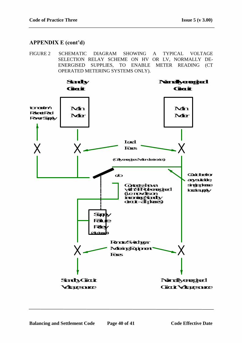
4. Combined Meters, Displays and Outstations Supplied via a Voltage Relay Selection
Scheme
With this option the integrated equipment would be connected to an appropriate single
phase voltage supply via a voltage relay selection scheme such that whilst this circuit
was de-energised it would receive it's voltage supply only, from the adjacent circuit.
However, when this circuit was energised it would be fed with both voltage and
current from the measured circuit. This arrangement is shown in Figure 2 overleaf and
is only suitable for use with CT operated Metering Systems.
Code of Practice Three Issue 5 (v 3.00)
Balancing and Settlement Code Page 40 of 41 Code Effective Date
APPENDIX E (cont’d)
FIGURE 2 SCHEMATIC DIAGRAM SHOWING A TYPICAL VOLTAGE
SELECTION RELAY SCHEME ON HV OR LV, NORMALLY DE-
ENERGISED SUPPLIES, TO ENABLE METER READING (CT
OPERATED METERING SYSTEMS ONLY).
Standby
Circuit
Normally energised
Circuit
Local
Fuses
Main
Meter
Contacts shownwith SFR de-energised(i.e. no volts on incoming Standbycircuit - all phases)
Normally energised
Circuit Voltage source
Remote/Switchgear
Metering Equipment
Fuses
(Only energises Meter electronics)
Supply
Failure
Relay
Main
Meter
c/o
Standby Circuit
Voltage source
to modem/
Paknet Pad
Power Supply
Could be from
any suitable,
single phase
local supply
(All phases)

Code of Practice Three Issue 5
(v 3.00)
Balancing and Settlement Code 41 Code Effective Date
APPENDIX F GENERIC DISPENSATIONS
The issue of this Code of Practice does not revoke the following Dispensations and they are valid against this issue of the Code of Practice:
DISPENSATION
NUMBER
DESCRIPTION OF DISPENSATION (FORM D4) DISPENSATION
FROM ISSUE
157 Agreed that Code of Practice G Metering Equipment installed prior to 1st April 1993, but not
Registered with the SSA3 until some later date, could remain on circuit provided that there was no
material change to that Metering Equipment.
Issue 1
3 Original references to the SSA in this context are deemed to have been replaced by the Central Registration Agent (CRA).