Code of Practice for Traction & Rolling January 1996 Stock ... iss 1.pdf · Code of Practice for...
69
Code of Practice GM/RC2509 Issue One Date January 1996 Page 1 of 69 R A I L T R A C K 1 Code of Practice for Traction & Rolling Stock - Mechanical Coupling Systems Code of Practice for Traction & Rolling Stock - Mechanical Coupling Systems Synopsis This Code of Practice details the main types of rail vehicle mechanical coupling systems currently in use on rail vehicles that operate on Railtrack controlled infrastructure. It also provides basic information on the requirements for ensuring safe and reliable mechanical coupling system design for new or modified rail vehicles. This document is the property of Railtrack PLC. It shall not be reproduced in whole or in part without the written permission of the Controller, Safety Standards, Railtrack PLC. Published by Safety & Standards Directorate Railtrack PLC Floor 2, Fitzroy House 355 Euston Road London NW1 3AG © Copyright 1996 Railtrack PLC Submitted by .................................................................................................. B.K. Wilkinson Nominated Responsible Manager Approved by .................................................................................................. C.P. Boocock Chairman, Traction & Rolling Stock Subject Committee Withdrawn Document Uncontrolled When Printed
Transcript of Code of Practice for Traction & Rolling January 1996 Stock ... iss 1.pdf · Code of Practice for...

Code of Practice
GM/RC2509
Issue One
Date January 1996
Page 1 of 69
R A I L T R A C K 1
Code of Practice for Traction & RollingStock - Mechanical Coupling Systems
Code of Practice for Traction & Rolling Stock - Mechanical Coupling Systems
Synopsis
This Code of Practice details the main types of rail vehicle mechanical coupling systems currently in use on rail vehicles that operate on Railtrack controlled infrastructure. It also provides basic information on the requirements for ensuring safe and reliable mechanical coupling system design for new or modified rail vehicles.
This document is the property of Railtrack PLC. It shall not be reproduced in whole or in part without the written permission of the Controller, Safety Standards, Railtrack PLC. Published by Safety & Standards Directorate Railtrack PLC Floor 2, Fitzroy House 355 Euston Road London NW1 3AG
© Copyright 1996 Railtrack PLC
Submitted by
..................................................................................................
B.K. Wilkinson Nominated Responsible Manager Approved by .................................................................................................. C.P. Boocock Chairman, Traction & Rolling Stock Subject Committee
Withdrawn Document Uncontrolled When Printed

Code of Practice
GM/RC2509
Issue One
Date January 1996 Page 2 of 69
2 R A I L T R A C K
Code of Practice for Traction & Rolling Stock - Mechanical Coupling Systems
This page is intentionally blank.
Withdrawn Document Uncontrolled When Printed

Code of Practice
GM/RC2509
Issue One
Date January 1996
Page 3 of 69
R A I L T R A C K 3
Code of Practice for Traction & RollingStock - Mechanical Coupling Systems
Contents Section Description Page
Part A Issue record 2 Responsibilities and distribution 2 Health and Safety Responsibilities 2 Supply 2
Part B 1 Purpose. 3 2 Scope. 3 3 Definitions and Abbreviations. 4
4 Introduction. 5 5 Coupling System Types. 6 6 Introduction of New Coupling System Types. 8 7 Compatibility Between Coupling Systems. 8 8 Rescue, Assistance and Transfer of Vehicles fitted with Incompatible Coupling Systems. 9 9 Railway Group Standards Requirements. 9 10 UIC Requirements. 9 11 Operating Considerations. 10 12 Mechanical Strength and Material Properties. 11 13 Energy Absorption. 12 14 Compliance with Gauge. 14 15 Avoiding Derailment. 14 16 Testing. 15 17 Maintenance Requirements. 16
Appendices A Summary of Coupler Types Fitted to Traction & Rolling Stock
Operating on Railtrack Controlled Infrastructure. 17 B Coupling System Descriptions. 20
B.1 Screw Couplers 20 B.2 Instanter Couplers 26 B.3 Drophead Buckeye Couplers 29 B.4 Alliance Couplers 39 B.5 BSI Couplers 43 B.6 Tightlock Couplers 46 B.7 Scharfenberg Couplers 52 B.8 Semi-Permanent Couplers. 55
C Summary of Compatibility Between Coupling Systems. 57 D Adaptor Couplers and Equipment. 58 E Design of Coupling Systems to Avoid Derailment. 59 F Sources of Height Variations Between Vehicles or
Coupling Equipment. 64 G Minimum Track Geometry Data Typically Used for Vehicle
Design Purposes. 65
References 66
Withdrawn Document Uncontrolled When Printed

Code of Practice
GM/RC2509
Issue One
Date January 1996 Page 4 of 69
4 R A I L T R A C K
Code of Practice for Traction & Rolling Stock - Mechanical Coupling Systems
Part A
Issue record This Code of Practice will be updated when necessary by distribution of a
complete replacement. Amended or additional parts of revised pages will be marked by a vertical
black line in the adjacent margin. Issue Date Comments One January 1996 Original Document
Responsibilities This Code of Practice is of relevance to all organisations with a and distribution responsibility for specifying, designing or installing rail vehicle mechanical
coupling systems on rail vehicles.
Health and Safety In approving this Code of Practice, Railtrack PLC makes no warranties,
Responsibilities express or implied, that compliance with all or any Railway Group Standards is sufficient on its own to ensure safe systems of work or operation. Each user is reminded of its own responsibilities to ensure health and safety at work and its individual duties under health and safety legislation.
Supply Controlled and uncontrolled copies of this Code of Practice must be
obtained from The Catalogue Secretary, Safety & Standards Directorate, Railtrack PLC, Floor 2, Fitzroy House, 355 Euston Road, London, NW1 3AG.
Withdrawn Document Uncontrolled When Printed

Code of Practice
GM/RC2509
Issue One
Date January 1996
Page 5 of 69
R A I L T R A C K 5
Code of Practice for Traction & RollingStock - Mechanical Coupling Systems
Part B
1 Purpose 1.1 This Code of Practice provides details and descriptions of the main types of mechanical coupling systems currently in use on rail vehicles operating on
Railtrack controlled infrastructure. It also provides guidance on mechanical coupling system design and operating criteria to promote safe operation and interworking in normal service and minimise damage to vehicles and risk to passengers and staff in the event of collisions or during coupling operations.
1.2 It also provides information for organisations responsible for commissioning new or modifying existing rail vehicles which are specified to interwork with existing stock either by a compatible coupling system or by the use of adaptor
couplers.
1.3 The information provided is for guidance only and use of the information or duplication of existing designs does not necessarily constitute compliance with the mandatory requirements associated with coupling systems and operating practice or specific technical and performance requirements contained within vehicle procurement or modification specifications. 1.4 In the analysis of mechanical coupling system performance between new or modified vehicles the organising body is advised to procure full details of the coupling system and vehicle parameters of existing vehicles from the vehicle owner.
2 Scope 2.1 This Code of Practice provides details of typical couplers in current use on rail
vehicles of the following vehicle types which operate over Railtrack controlled infrastructure where coupling and uncoupling in service or on depot is required:- • Main line locomotives • Shunting locomotives • DMUs • EMUs • Locomotive hauled coaching stock • Driving Trailers • HST • Freight vehicles • Vehicles used in international traffic between mainland Europe and the
United Kingdom. • On-Track Machines (required to operate or travel on Railtrack controlled
infrastructure outside a possession)
Withdrawn Document Uncontrolled When Printed

Code of Practice
GM/RC2509
Issue One
Date January 1996 Page 6 of 69
6 R A I L T R A C K
Code of Practice for Traction & Rolling Stock - Mechanical Coupling Systems
2.2 The coupling system descriptions (Appendix B) do not specifically cover the coupling systems of the following types of vehicles:- • Trains operated by London Underground Limited and light railway vehicles
that are confined to specific routes. • Trains that are operated by Eurotunnel Limited. • Independent snow-ploughs • Special purpose On-Track machines and vehicles used for track and
trackside maintenance required to operate or travel on Railtrack controlled infrastructure only in a possession.
• Preserved rail vehicles including steam, diesel and electric locomotives and rolling stock.
• AAR E/F type couplers which are only used on certain freight trains which operate in block formation.
• Centre buffer and 3 link chain couplers which are only used on intermediate vehicles of certain types of EMU subject to imminent withdrawal.
3 Definitions and 3.1 Definitions Abbreviations Coupling System See GM/TT0401
Coupler The element which mechanically connects the vehicles together. Automatic Coupler See GM/TT0401 Adaptor Coupler A type of coupler which enables vehicles with incompatible couplers to be connected together for the purposes of rescue and/or transfer. Emergency Screw Coupler A screw coupler which enables vehicles fitted with drawhooks to be connected together in circumstances where the installed screw coupler is unusable or where a screw coupler is not fitted.
Withdrawn Document Uncontrolled When Printed

Code of Practice
GM/RC2509
Issue One
Date January 1996
Page 7 of 69
R A I L T R A C K 7
Code of Practice for Traction & RollingStock - Mechanical Coupling Systems
3.2 Abbreviations AAR Association of American Railroads ARL Above Rail Level BR/BRB British Rail/British Railways Board BSI Bergische Stahl - Industrie CL Class (as in class of locomotive or train set, e.g. CL08, CL465) DMU Diesel Multiple Unit EMU Electric Multiple Unit HST High Speed Train (CL253 and CL254 train sets) MK Mark (as in type of coaching stock, e.g. MK1, MK2) IC InterCity TOE Trailer Open End (MK4 Vehicle) UIC International Union of Railways
4 Introduction 4.1 Various types of mechanical coupling systems are in use, each of which provides the following basic functions: *
A means of connecting and separating vehicles either by manual or automatic methods.
* A recoverable means of absorbing energy during coupling, rough shunting, minor collisions, braking and accelerating without damage to vehicle equipment, vehicle structures and cargo.
* A recoverable means of absorbing energy during coupling without causing discomfort or injury to passengers and train crew.
* A means of transferring tensile and compressive forces between vehicles during coupling, rough shunting, minor collisions, braking, accelerating and curving.
* A means of accommodating track and vehicle induced movements between adjacent vehicle ends without damage to vehicle end equipment or the risk of derailment.
4.2 In addition to the above, modern coupling systems for specific vehicle types
may also incorporate the following additional functions: • A recoverable means of absorbing energy during higher levels of collisions
without damage to vehicle equipment and structures and limiting injury to passengers and train crew.
• A means of preventing (in conjunction with the surrounding structure) overriding and transverse separation of vehicles during collisions and derailments.
• A means of providing a non recoverable longitudinal collapse of the coupling equipment or its connecting structure to allow engagement of anti climbers or bodyends as part of a controlled system of progressive collapse in severe collisions.
Withdrawn Document Uncontrolled When Printed

Code of Practice
GM/RC2509
Issue One
Date January 1996 Page 8 of 69
8 R A I L T R A C K
Code of Practice for Traction & Rolling Stock - Mechanical Coupling Systems
• A means of automatic connection and disconnection of power, control, communication and air supplies between vehicles.
4.3 A large range of different types of coupling equipment is available. Within
each type the physical geometry, characteristics and performance can be tailored to suit specific vehicle applications and duty. Selection of suitable equipment for each application is determined by meeting the following criteria: • The business requirements in terms of interworking with existing rail
vehicles. • The mandatory requirements contained within the relevant Railway Group
Standards and legislation (and where applicable the relevant UIC standards).
• The specific technical performance criteria contained within the vehicle engineering or performance specifications.
4.4 There is a wide range in the age of vehicles currently operating on Railtrack
controlled Infrastructure. During this period there has been considerable development in the performance of coupling equipment and successive development in technical standards. As a consequence certain existing vehicles are fitted with coupling equipment which may not meet all current standards or achieve the technical performance of available equipment. Wherever reasonably practicable new vehicles or existing vehicles subject to a change of use should be fitted with coupling systems which incorporate the advantages of the available high performance coupling equipment.
5 Coupling System 5.1 The coupling systems in current use can be broadly classified as follows:- Types a) Vehicles fitted with side buffers, drawhooks and screw couplers.
b) Vehicles fitted with side buffers, drawhooks and Instanter couplers. c) Vehicles fitted with side buffers, drawhooks and drophead Buckeye
automatic couplers which are manually convertible to couple with other Buckeye fitted vehicles or vehicles as described in a) above.
d) Vehicles fitted with Alliance automatic couplers. e) Vehicles fitted with BSI automatic couplers. f) Vehicles fitted with Tightlock automatic couplers. g) Vehicles fitted with Scharfenberg automatic couplers. h) Vehicles fitted with connection points to allow rescue and transfer by the
use of adaptor couplers carried on the vehicle. i) Vehicles fitted with semi permanent (bar) couplers. j) Vehicles fitted with Wedgelock couplers. k) Vehicles fitted with AAR E/F automatic couplers. l) Vehicles fitted with centre buffers and 3 link chain. m) Articulated vehicles with a shared bogie between vehicles The type of system in use is dependant on the type of vehicle, the interworking and the operating and performance requirements specified at the time of build or during modification. 5.2 Screw and Instanter couplers have been used to provide universal flexibility in train formation and are perpetuated to provide interworking with existing
Withdrawn Document Uncontrolled When Printed

Code of Practice
GM/RC2509
Issue One
Date January 1996
Page 9 of 69
R A I L T R A C K 9
Code of Practice for Traction & RollingStock - Mechanical Coupling Systems
stock. 5.3 Drophead Buckeye automatic couplers have been used to provide flexibility in the formation of locomotive hauled coaching stock trains and allow haulage by locomotives fitted with screw couplers whichever vehicle is positioned at the rake ends. However, most types of these vehicles (except for non passenger locomotive hauled coaching stock) now operate in fixed formation sets. They have also been used on the cab ends of early types of EMUs to provide automatic coupling between units in service and to retain provision for rescue and transfer by locomotives. 5.4 Alliance automatic couplers have been used to provide automatic coupling between intermediate vehicles to allow adjustments to train formation on depots, although most types of these vehicles now operate in fixed formation sets. 5.5 BSI automatic couplers are the current standard for DMUs where interworking between different unit types is required with provision for driver control of coupling/uncoupling at the cab ends. 5.6 Tightlock automatic couplers are the current standard for EMUs where interworking between different unit types is required with provision for driver control of coupling/uncoupling at the cab ends. Tightlock couplers are also used on intermediate vehicles of IC225 train sets. 5.7 Scharfenberg automatic couplers are used on CL373 (Eurostar) vehicles to provide automatic coupling between subsets and power vehicles. They will also be fitted to CL332. 5.8 Connection points are fitted to the cab ends of HST power cars. The connection points allow rescue and assistance by other HST sets and locomotives by means of adaptor couplers carried on the vehicle. 5.9 Semi-permanent (bar) couplers are used between intermediate vehicles of certain EMUs, DMUs, Victoria - Gatwick coaching stock and European Nightstock sub-set intermediate ends and certain types of freight stock used in block working where coupling/uncoupling is only required on depots 5.10 Wedgelock Couplers are used on some London Underground trains and CL483 Isle of Wight trains (which are ex London Underground trains). 5.11 AAR E/F couplers are used on certain types of intermediate freight vehicles which operate in block formation. 5.12 Centre buffer and 3 link couplers are used on intermediate vehicles of certain types of EMU and other vehicles not used for passenger services. Some vehicles with this type of coupler are subject to imminent withdrawal.
Withdrawn Document Uncontrolled When Printed

Code of Practice
GM/RC2509
Issue One
Date January 1996 Page 10 of 69
10 R A I L T R A C K
Code of Practice for Traction & Rolling Stock - Mechanical Coupling Systems
5.13 The type of coupling system in use on vehicles which are currently operating on Railtrack lines is listed in Appendix A. Descriptions of typical coupling systems covered by this Code of Practice are included in Appendix B accompanied by selected diagrams showing typical arrangements.
6 Introduction of 6.1 When considering the introduction of new coupler systems the following New Coupling aspects should be reviewed :- System Types a) The need to meet mandatory requirements defined in Railway Group
Standards, any legislation and Government requirements. b) The need to meet operating and performance requirements. c) The adaptability of the physical geometry, characteristics and performance
of coupler systems in current use to suit specific vehicle applications and duty.
d) The possible need to obtain certification under the process for the Engineering Acceptance of Rail Vehicles (see GM/RM2500 [28]).
e) The need to meet interworking requirements with existing types of vehicle where applicable.
f) The need to prevent connection to existing vehicle types which are incompatible for normal service operation.
g) The risk associated with any need to establish specific working practices in the exceptional circumstances when there is a need to connect incompatible coupler systems.
h) The need to provide for rescue, and assistance with other vehicles as defined by the Railtrack access agreements.
i) The need to provide for dead haulage at line speeds to workshops and maintenance facilities and to allow for shunting movements on depots in accordance with reference [11].
j) The need for coupling systems with autocouplers to include a positive indication by physical or other means that can be readily used to confirm that coupling has been achieved.
7 Compatibility 7.1 A summary of compatibility between coupling systems is shown in Between Coupling Appendix C. This table details the systems which are directly compatible and Systems the specific arrangements where incompatible systems are able to couple by the use of adaptor couplers or equipment for the purpose of depot movements,
rescue, assistance and transfer. The table contents are not comprehensive and do not cover all the restrictions which appertain to individual vehicles types or combinations. Details of restrictions and operating procedures for coupling between vehicles are covered in reference [10] and in the Train Crew Working Instructions and Operating Manuals for each type of vehicle or train set.
Withdrawn Document Uncontrolled When Printed

Code of Practice
GM/RC2509
Issue One
Date January 1996
Page 11 of 69
R A I L T R A C K 11
Code of Practice for Traction & RollingStock - Mechanical Coupling Systems
8 Rescue, Assistance 8.1.1 Adaptor or emergency screw couplers are provided for use between and Transfer of incompatible coupler types for the rescue and assistance of failed trains Vehicles fitted with or to enable shunting movements on depots. Incompatible Coupling Systems 8.1.2 Adaptor couplers are also used in specific cases for transfer of empty stock between depots and manufacturing or repair facilities; however, in these
cases it is normal to use barrier or match vehicles specifically designed for use with certain types of stock. 8.1.3 Adaptor and/or emergency screw couplers are either carried on vehicles or are held at depots. The requirements for vehicle and/or depot provision of adaptor and/or emergency screw couplers are subject to the operating requirements in the area of operation and the track access agreement with Railtrack. 8.1.4 Known adaptor couplers in current use are listed in Appendix D. The use of existing adaptor couplers for new or modified vehicles is subject to their suitability for the application and compliance with the relevant Railway Group Standards. 8.2 Barrier vehicles currently exist for use with the following type of stock to allow haulage by locomotives fitted with a screw coupler: • HST vehicles fitted with Alliance couplers. • EMU vehicles fitted with Alliance couplers. • EMU vehicles fitted with Tightlock couplers. • MK4 vehicles fitted with Tightlock couplers. • DMU vehicles fitted with BSI couplers. • Eurostar vehicles fitted with Scharfenberg couplers. (Certain converted
CL 73 and CL 08 shunters are also able to directly couple to Eurostar trains).
9 Railway 9.1 The Railway Group Standards directly applicable to mechanical coupling Group Standards systems are listed in references [2], [5] and [6]. Associated Railway Group Requirements Standards relevant to coupling systems are listed in references [1], [3] and [4]. The Standards are the minimum requirements which apply to all new rail vehicles
and also to existing vehicles when undergoing engineering change in so far as it is reasonably practicable to incorporate them. Coupling systems on some
existing vehicles may not comply, but arrangements are in place to ensure safety and safe interworking.
10 UIC 10.1 Vehicles which are required to operate between the UK and mainland Requirements Europe in international traffic are required to comply with the UIC requirements. The requirements which are directly applicable to coupling systems and track
geometry are detailed in a collection of UIC leaflets references [12] to [24]. These references apply to vehicles fitted with side buffers and screw couplings. UIC leaflets also exist for the provision of automatic couplers, however this type of system has not yet been implemented.
Withdrawn Document Uncontrolled When Printed

Code of Practice
GM/RC2509
Issue One
Date January 1996 Page 12 of 69
12 R A I L T R A C K
Code of Practice for Traction & Rolling Stock - Mechanical Coupling Systems
11 Operating 11.1 Coupling/Uncoupling Considerations 11.1.1 The coupling and uncoupling of vehicles and the use of adaptor couplers
is controlled by the Railtrack Rule Book reference [10] (in particular see Rule Book Appendices 2,3,4,5,7,11 and 13), the Train Crew Working Instructions and Operating Manuals for individual vehicle types and the Operating
departments staff training procedures including reference [9]. 11.1.2 Coupling and uncoupling of vehicles (except for intermediate vehicles which are semi permanently coupled) may be required on any part of the Railtrack controlled infrastructure and other location. For practical purposes coupling/uncoupling is not normally required on simple and reverse curves below 160m radius, unless otherwise specified. Special arrangements need to be in place where the gathering range of coupler systems on some existing rail vehicles is insufficient to meet the reverse curve criteria. 11.1.3 Coupling system design and equipment should therefore, as a minimum requirement, accommodate coupling and uncoupling on all types of simple and reverse curves greater than or equal to 160m radius. In the case of automatic couplers any difference between heights of vehicles (see Appendix F) should also not prevent coupling and uncoupling. 11.1.4 Semi permanent (bar) couplers are generally only coupled or uncoupled on depots and workshops on straight or near straight track. However, the coupler design should include features to allow as much gathering between the couplers as is practicable. 11.1.5 Coupling systems with autocouplers should include a positive indication by physical or other means that can be readily used to confirm that coupling has been achieved. Where this facility is not currently fitted or cannot be readily confirmed this should be remedied wherever practicable. 11.2 Operation over minimum track geometry 11.2.1 The design, installation and geometry of track is defined in references [7] and [8]. The minimum track geometry which is normally specified for the purposes of vehicle procurement and to which most existing vehicles were designed is listed in Appendix G. This Appendix also covers the basic minimum track geometry which may be expected in depots, workshops and sidings. 11.2.2 There are a small number of locations (covered by local operating instructions) where specific combinations of vehicles are not permitted to run because of the risk of buffer locking in propelling situations. Wherever practicable the couplings fitted to vehicles should avoid the necessity for special local instructions.
Withdrawn Document Uncontrolled When Printed

Code of Practice
GM/RC2509
Issue One
Date January 1996
Page 13 of 69
R A I L T R A C K 13
Code of Practice for Traction & RollingStock - Mechanical Coupling Systems
11.2.3 The coupling system design and equipment should therefore allow any permitted combination of vehicles in any permitted operating condition to operate over the track features described in references [7] and [8] and the minimum track geometries listed in Appendix G unless otherwise specified in vehicle procurement or modification specifications. 11.3 Staff Health and Safety 11.3.1 The design of new coupling systems shall not expose staff to risk of injury either by the operation of the coupling equipment or by requiring staff to stand between vehicles whilst vehicle movements are taking place during coupling or uncoupling operations. 11.3.2 Wherever possible coupling/uncoupling operations should minimise the need for staff to enter the space between vehicles by the use of remote controls or uncoupling bars. Where it is necessary for staff to enter the space between vehicles for the purpose of coupling/uncoupling adequate room for staff to manoeuvre and operate equipment shall be provided. In the case of screw couplings the requirements of reference [13] provide a defined space envelope to enable staff to operate between vehicles. 11.3.3 Where automatic coupling/uncoupling is not possible the weight of coupling equipment (including adaptor couplers) which requires man-handling, or the forces required to operate the equipment, should comply with the provisions of reference [25]. Additionally, such requirements should be commensurate with the stature of the staff recruited by the operator for the purposes of coupling duties. A suitable guide-line for evaluating physical limitations for staff engaged in such duties is the “Ergonomics Standards and Guide-lines for Designers” reference [26].
12 Mechanical 12.1 Mechanical strength requirements for coupling equipment are defined in Strength and reference [2]. Material Properties 12.2 Coupling equipment components should meet the specified mechanical
strength requirements, the material properties, metallurgical condition and surface treatments. In addition, coupling equipment components should be selected to meet the duties of the operating conditions particularly with respect to fatigue loads and snatch loads during train operation and impact loads during coupling and the wear performance of moving parts.
12.3 Wherever practicable the design of coupling equipment components
should avoid high rates of wear and the effects of corrosion. Items subject to high rates of wear or the effects of corrosion should be fitted with easily replaceable parts, liners or bushing.
Withdrawn Document Uncontrolled When Printed

Code of Practice
GM/RC2509
Issue One
Date January 1996 Page 14 of 69
14 R A I L T R A C K
Code of Practice for Traction & Rolling Stock - Mechanical Coupling Systems
13 Energy 13.1 During Coupling Absorption 13.1.1 Each vehicle (or rake) should be capable of absorbing its own energy
during coupling operations. The calculation of kinetic energy should be based on the relevant mass of the
vehicle. Some masses (eg passenger load) are normally ignored in the calculation of kinetic energy as they are considered to act as decoupled masses for calculation purposes. In specific scenarios the influence of such apparent decoupled masses may have to be considered in the calculation of kinetic energy.
13.1.2 Energy absorption is normally accommodated by side buffers on vehicles
fitted with screw couplers and by elements integral with the coupler or between the coupler and the vehicle body on vehicles fitted with automatic or semi permanent couplers.
13.1.3 Coupling speeds are variable according to driver control and operating
practice. In the case of vehicles which are coupled with staff or passengers on board, normal practice is to stop 2m ahead of the stationary vehicle/train and move slowly towards the stationary vehicle/train to couple. In these conditions
typical coupling speeds up to 0.5 m/s, and occasionally up to 1 m/s, are encountered. However, in less controlled conditions all types of vehicles may be subject to occasional coupling speeds up to 2 m/s.
13.1.4 In the case of vehicles which couple with traincrew and passengers on
board the accelerations imparted to the vehicles at coupling speeds up to 0.5 m/s should not exceed those specified in reference [4]. To minimise the risk of injury to passengers and traincrew the coupling equipment design should as far as reasonably practicable minimise the accelerations due to higher coupling speeds.
13.1.5 In the case of coupling at speeds up to 2 m/s:
• The peak forces generated during coupling should not exceed the longitudinal proof loads at the drawgear or buffer mounting positions defined in reference [1].
• The coupling equipment, vehicle structure and vehicle equipment should not sustain any damage.
• The elements absorbing the energy should be fully and automatically recoverable.
Withdrawn Document Uncontrolled When Printed

Code of Practice
GM/RC2509
Issue One
Date January 1996
Page 15 of 69
R A I L T R A C K 15
Code of Practice for Traction & RollingStock - Mechanical Coupling Systems
13.2 During Train Operation 13.2.1 The flexible elements within the coupling system should be selected so as not to cause any undesirable dynamic effects, and to avoid frequency
coincidence or excitation with other modes of vibration, of the vehicle or train during normal operation which may include the effects of braking or sudden
changes in tractive power. 13.2.2 In train formations which contain non rigid couplings (e.g. Screw,
Instanter, Buckeye and Alliance couplers) the forces generated throughout the train when the train moves from rest shall be absorbed without: * Generating accelerations to the vehicle bodies which would cause injury to
traincrew or passengers or damage to cargo. * Exceeding the coupler or vehicle proof loads defined in reference [1] or
causing any damage to vehicle equipment. 13.3 During Collisions 13.3.1 In addition to the requirements for energy absorption during coupling (See Clause 13.1), additional energy absorption within the coupling equipment may be specified for vehicles which carry train crew and passengers in order to
minimise risks of injury to train crew and passengers and to minimise damage to vehicles during collisions or derailment. 13.3.2 The requirements may include absorbing the energy of a collision with a
combined closing speed of up to 4 m/s within the self recoverable stroke of the energy absorbing elements so that the requirements defined in Clause 13.1.5 are met under a combined closing speed of 4m/s.
13.3.3 In addition, to meet the structural collapse requirements of reference [1]
the coupling equipment or its connection to the vehicle structure may contain non-recoverable elements which allow anti-climbers or body ends to engage above a specified closing speed.
In these cases activation of the non-recoverable element should be at a force level
with an adequate margin above the peak force generated by the recoverable element at the maximum specified closing speed. A visible means of checking that the non recoverable element has not been activated should be provided.
Withdrawn Document Uncontrolled When Printed

Code of Practice
GM/RC2509
Issue One
Date January 1996 Page 16 of 69
16 R A I L T R A C K
Code of Practice for Traction & Rolling Stock - Mechanical Coupling Systems
13.3.4 The coupling equipment may be an integral part of the mechanism by which the vertical and transverse load requirements between vehicles detailed in
references [1] and [2] are met. In such cases the requirements apply during activation of both the recoverable and non-recoverable elements. In addition,
activation of the non-recoverable element should not allow separation of the vehicles under tensile loading (where vehicles are coupled) post collision up to a
force equivalent to the proof loads of the coupling equipment defined in reference [2].
14 Compliance With 14.1 Gauging requirements are defined in reference [3]. Gauge
Whilst it may be necessary to maximise the size of side buffers to minimise the risk of buffer locking on certain vehicles, the size (and shape) of buffers is constrained by the need to ensure compliance with the above standard. 14.2 Screw couplers in an extended position when not in use may also infringe the gauge and therefore all vehicles fitted with screw couplers are required to be fitted with a retention bracket. The bracket should also restrain the coupler to prevent damage to adjacent equipment.
15 Avoiding Derailment 15.1 Vehicle coupling systems should allow any permitted or specified coupling combination to operate safely and without risks of damage or derailment when operating over Railtrack controlled infrastructure and in sidings, depots and workshops.
15.2 The design, installation and geometry of track is defined in references [7] and [8] and its associated reference documents. Minimum track geometry typically used for vehicle design cases is shown in Appendix G. 15.3 Risk of damage or derailment is avoided by undertaking analysis to ensure that the design of the coupling system, its operation and use and its effect on the vehicles and track interface under all operating conditions is suitable. It should not be possible for circumstances to develop where insufficient freedom of movement or interaction between inter-vehicle equipment generates forces between the wheels and the track that exceed those specified in reference [5]. The type and extent of analysis will vary according to vehicle types, coupling system, coupling combinations and operating conditions. A resume of the parameters and conditions which need to be considered is contained in Appendix E.
Withdrawn Document Uncontrolled When Printed

Code of Practice
GM/RC2509
Issue One
Date January 1996
Page 17 of 69
R A I L T R A C K 17
Code of Practice for Traction & RollingStock - Mechanical Coupling Systems
16 Testing 16.1 Technical Performance 16.1.1 All new coupler systems, or significant modifications to existing coupler
systems should be subject to sufficient testing to confirm that the equipment and the installation on the vehicle meets the mandatory requirements and the specified technical performance criteria. The type of tests will vary according to the vehicle and equipment type and the degree of variation from existing designs. The requirements which may need verification by testing are:
• Mechanical proof, ultimate and fatigue strength in all modes of loading for all
elements of coupling equipment and the attachments to the vehicle body. • Static and dynamic characteristics of all flexible and energy absorbing
elements. • Coupling and uncoupling within the range of track geometry and vehicle
height conditions specified for the vehicle type. • Freedom of movement of coupling equipment to accommodate inter-vehicle
movement on minimum curves and worst case operating conditions. • Avoidance of buffer locking or other undesirable interaction between
intervehicle equipment (where calculations have identified a potential risk). • Functionality and wear resistance for the type of duty and operational life of
the equipment. 16.2 Manufacturing Specifications 16.2.1 Manufacturing specifications and procedures are required to ensure that
manufacturing methods, treatments and materials produce a component or assembly that meets the requirements of the standards required by the technical specification.
16.2.2 The requirements of the specification should, where appropriate, contain
testing and inspection procedures for the following areas: • Material chemical composition. • Material properties including hardness, ductility and impact resistance. • Mechanical proof and ultimate strength. • Measurement of physical dimensions for components and assemblies. • Visual examination for surface defects. • Non destructive testing for defects in forgings, castings and welded joints. • Component assembly and functioning of assembled equipment. • Whole assembly proof and ultimate strength.
The level and type of testing, inspection and sampling methods are subject to
agreement between supplier and purchaser according to the equipment type and batch size and should be adequate to satisfy Quality Audits by a Third Party.
16.2.3 Coupling system equipment should only be procured from an approved
supplier, see reference [29].
Withdrawn Document Uncontrolled When Printed

Code of Practice
GM/RC2509
Issue One
Date January 1996 Page 18 of 69
18 R A I L T R A C K
Code of Practice for Traction & Rolling Stock - Mechanical Coupling Systems
16.3 Documentation and Control 16.3.1 All testing procedures and test reports shall be controlled by an approved
and auditable quality system. 16.3.2 Where appropriate for control purposes equipment should have a means
of identification which shall include supplier, date of manufacture (or overhaul) and batch number. Items which are physically identical but are supplied in chemically different materials or with different strength grades should also be clearly identifiable.
17 Maintenance 17.1 All coupling equipment requires periodic inspection, maintenance and Requirements overhaul to ensure safe and reliable operation. The requirements and
periodicities are dependant on the type of equipment, duty, manufacturers recommendations, the vehicle maintenance regime and experience derived from failure/operating records.
17.2 Adequate access for on-vehicle inspection and maintenance purposes should
be provided on all coupling equipment installations. 17.3 Specific inspection, maintenance and overhaul procedures and testing
documentation for each item of coupling equipment should be provided. The documentation should form part of a controlled and auditable system for each vehicle or coupler type.
Withdrawn Document Uncontrolled When Printed

Code of Practice
GM/RC2509
Issue One
Date January 1996
Page 19 of 69
R A I L T R A C K 19
Code of Practice for Traction & RollingStock - Mechanical Coupling Systems
APPENDIX A Summary of Coupler Types Fitted to Traction and Rolling Stock Operating on Railtrack Controlled Infrastructure.
A1 VEHICLE TYPE COUPLER TYPE
Locomotives Class 08, 09, 20, 31, 33/0, 33/2, 37, 47, 56, 58, 59, 60, 86, 87, 90/1 and 92
Screw both ends
Class 33/1, 73, 90/0, and 91 Drophead Buckeye both ends
A2 Passenger VEHICLE TYPE COUPLER TYPE
Carrying Locomotive hauled Coaching Stock and Driving Trailers
MK2 DBSO Class 488 subsets Class 489 MK3 DLV (also known as DVT) All other MK1,2,3 passenger vehicles MK4DLV (also known as DVT) MK4 passenger vehicles
Drawhook only cab end, Drophead Buckeye non cab end, Drophead Buckeye sub set ends, Bar coupler intermediate ends. Drophead Buckeye both ends. Drophead Buckeye both ends Drophead Buckeye both ends. Tightlock non cab end. Screw cab end. Tightlock (Not EMU compatible) both ends, except Drophead Buckeye non gangwayed end of TOE.
A3 Non VEHICLE TYPE COUPLER TYPE
Passenger Locomotive hauled Coaching Stock
NJ (GUV), NKA, NLX, NOX (GUV), NP (GUV) and NX (GUV)
Screw both ends.
(Including Post Office & Motorail Vans)
NAA, NBA, NCX, ND(BG), NE(BG), NF (BG), NH (BG), NMV, NRX, NPX (GUV), NS (POS), NT (POT) and NUG (BPOT)
Drophead Buckeye both ends.
A4 High Speed VEHICLE TYPE COUPLER TYPE
Train (HST) Sets
MK3 Passenger Vehicles Power Cars (CL43) Channel Tunnel Nightstock
Alliance both ends Alliance non cab end, connection point cab end. UIC at sub-set ends Bar coupler at intermediate ends
Withdrawn Document Uncontrolled When Printed

Code of Practice
GM/RC2509
Issue One
Date January 1996 Page 20 of 69
20 R A I L T R A C K
Code of Practice for Traction & Rolling Stock - Mechanical Coupling Systems
A5 CL373 VEHICLE TYPE COUPLER TYPE
Eurostar Sets R1 - R9 and R10 - R18 Subsets Power Cars
Scharfenberg outer ends, intermediate vehicles are coupled by common bogie. Scharfenberg both ends.
A6 Diesel VEHICLE TYPE COUPLER TYPE
Multiple Units Class 101, 116, 117, 118, 119 and 121 Class 141, 142, 143, and 144, Class 150, 153, 155, 156, 158, 159, 165 and 166
Screw both ends. BSI cab ends, Bar intermediate ends. BSI all ends.
A7 Electric VEHICLE TYPE COUPLER TYPE
Multiple Units Class 302, 303, 304, 305, 308, 309, 310 and 312 (all 25kv) Class 411, 412, (413, 414, 415, 416 withdrawn), 421, 422 and 423 (all 750vdc) Class 313, 314, 315, 317, 318, 319, 320, 321, 322, and 323 (all 25kv, Class 313 319 and 365 are 25kv and 750vdc). Class 455, 456, 465, 466, 507 and 508 (all 750vdc). Class 325 (25kv and 750vdc) Class 332 (25kv) Class 442 (750vdc) Class 483 (Isle of Wight stock) Class 205 and 207 DEMUs
Drophead Buckeye cab ends, Alliance intermediate ends. Drophead Buckeye cab ends, Alliance intermediate ends Tightlock cab ends, Bar intermediate ends. Tightlock cab ends, Bar intermediate ends. Drophead Buckeye cab ends, Bar intermediate ends. Scharfenberg cab ends, Bar intermediate ends. Drophead Buckeye cab ends, Bar intermediate ends. Wedgelock cab ends. Bar coupler at intermediate ends. Drophead Buckeye cab ends, Alliance intermediate ends
Withdrawn Document Uncontrolled When Printed

Code of Practice
GM/RC2509
Issue One
Date January 1996
Page 21 of 69
R A I L T R A C K 21
Code of Practice for Traction & RollingStock - Mechanical Coupling Systems
A8 Freight The majority of freight vehicles are fitted at both ends with a drawhook for use Vehicles with one of the following types of coupler:
* Screw coupler. * Instanter coupler (some older vehicles may still have 3 link chain
type coupling). * International screw coupler (for vehicles used in international traffic).
In addition: • Freightliner rakes are fitted with screw couplers at both outer ends of vehicle
rakes and bar couplers at the intermediate positions. • Certain vehicles, e.g. flat wagons and ironstone tippers, are fitted with
buckeye couplings or AAR E/F couplers. • Detailed listings of coupler types fitted to individual vehicles can be obtained
from the Rolling Stock Library, Railway Technical Centre, London Road, Derby.
Withdrawn Document Uncontrolled When Printed

Code of Practice
GM/RC2509
Issue One
Date January 1996 Page 22 of 69
22 R A I L T R A C K
Code of Practice for Traction & Rolling Stock - Mechanical Coupling Systems
APPENDIX B Coupling System Descriptions
B.1 Screw Couplers B 1.1 Usage Locomotives (except those fitted with Buckeye couplers), first generation DMUs, the majority of freight vehicles (including those used in international traffic), and some types of non passenger carrying coaching stock. B 1.2 System Components There are a large number of different types and configurations but each type consists of the following elements: • A screw coupler attached to a drawbar. • A drawbar comprising a drawhook and a means of attaching the drawbar
to the vehicle structure. • A drawbar spring unit to absorb tensile shock loads between vehicles. • Side buffers to absorb compressive loads between vehicles during coupling
and train operation. • A screw coupler stowage bracket to allow screw coupler stowage without
infringing gauge. B 1.3 System Types Two basic types exist, but within each type components and configuration vary according to vehicle type, manufacturer, usage and date of build. These types are: a) Where the drawbar has no freedom to rotate in the horizontal plane and
therefore angular or lateral displacement between vehicles is accommodated by articulation between the screw coupler and drawbar.
b) Where the drawbar has freedom to rotate in the horizontal plane and therefore angular displacement between vehicles is mainly accommodated by rotation of the drawbars about the drawbar pivots.
Type a) is principally used on some short to medium length freight vehicles and Class 08 shunting locomotives. Type b) is used on all mainline locomotives, non passenger carrying coaching stock and medium to long length freight vehicles. This type is the preferred arrangement. Diagram B1.1 shows a typical arrangement for locomotives Diagram B1.2 shows a typical arrangement for freight vehicles Diagram B1.3 shows a typical arrangement for freight vehicles fitted with UIC drawgear.
Withdrawn Document Uncontrolled When Printed

Code of Practice
GM/RC2509
Issue One
Date January 1996
Page 23 of 69
R A I L T R A C K 23
Code of Practice for Traction & RollingStock - Mechanical Coupling Systems
B 1.4 System Descriptions B 1.4.1 Screw Couplers The screw coupler allows adjustment in its length to enable the coupler to be tensioned with the buffers in contact or slightly compressed when on straight track. Adjustment is necessary to accommodate a range of buffer face to drawhook eye dimensions found on different vehicle types. In the minimum length position for any vehicle combination at least 2 threads should remain proud of each buckle (with a maximum length of 3 threads proud of each buckle for standard UIC position coupler/buffer). The screw coupler accommodates different drawhook heights and differential vertical movements between vehicles by rotation in the attachment to the drawbar and in the drawhook. Articulation in the horizontal plane is accommodated in a similar manner but also by rotation of the drawbar about its pivot when the drawbar fitted has freedom to do so (see 1.3 b). A range of screw coupler types are in use to suit different vehicle types and strength requirements and to suit requirements for operation in international traffic. Attachment to drawbars is by pin, collar and split pin through the drawbar or by means of a flattened section on the link which allows the coupler to be installed by passage through a slot on the top of the drawbar. BR Drg No. B1-C0-9029821 shows types of screw coupler in current use. B 1.4.2 Drawbars A range of drawbars are in use to suit different vehicle types, hook profiles, strength requirements, connection methods and to suit requirements for operation in international traffic. Typical connection methods and arrangements to allow rotation are shown in Diagrams B1.1, B1.2 and B1.3. Drawbars are restrained in the vertical plane by housings attached to the headstock which also (where designed to do so) allows the drawbar to pivot in the horizontal plane. The housings (where designed to do so) allow tensioning of the drawbar to preload the spring units. Spring units which are preloaded by tensioning the tail pin normally feature housings which have replaceable wear pads. B 1.4.3 Drawbar Spring Units Drawbar spring units universally consist of a stack of rubber elements with steel dividing plates. The type and number of elements vary according to vehicle type and operation. All spring units are preloaded either by tensioning the drawbar against the headstock or by tensioning the tailpin.
Withdrawn Document Uncontrolled When Printed

Code of Practice
GM/RC2509
Issue One
Date January 1996 Page 24 of 69
24 R A I L T R A C K
Code of Practice for Traction & Rolling Stock - Mechanical Coupling Systems
B 1.4.4 Buffers Buffers are either rubber spring types or hydraulic/gas types. Buffer characteristics and strokes are selected according to vehicle type, energy absorption, strength and peak load requirements and duty. Buffer heads are profiled in the vertical and horizontal planes to minimise offset loadings during curve negotiation. Buffer head shapes and size are selected to minimise the risk of lateral or vertical buffer locking (or combinations thereof) during inter-vehicle movement generated by vehicle height differentials, dynamic movements and curve negotiation. B 1.5 System Standards Specific requirements for each type of vehicle are defined by the vehicle specification. Guidance notes for freight vehicles are defined in reference [27]. Requirements for vehicles which operate in international traffic are defined by UIC documents references [12] - [24].
Withdrawn Document Uncontrolled When Printed

Code of Practice
GM/RC2509
Issue One
Date January 1996
Page 25 of 69
R A I L T R A C K 25
Code of Practice for Traction & RollingStock - Mechanical Coupling Systems
Diagram B 1.1 : Typical Screw Coupler Arrangement For Locomotives (Dimensions Nominal)
RA
IL L
EV
EL
1740
BU
FFE
R C
EN
TRE
S
508
or
55
9
1054CENTRE OF BUFFERS
1054CENTRE OF DRAWHOOK EYE
352
VE
RTI
CA
L S
UP
PO
RT
VE
H.
C L
11o
11o
DR
AW
BA
R S
PR
ING
UN
IT
FULC
RU
M P
LATE
DR
AW
BA
R
BE
AR
ING
PLA
TE
114
NO
TES
1. B
ased
On
CI8
6/87
2. R
efer
ence
Drg
s- A
rran
gem
ent
B2-
S-S
9010
051
- Scr
ew C
oupl
ing
L-A
0-14
75
- Dra
wba
r SL/
BR
-112
8
- Dra
wba
r Spr
ing
Uni
t (S
ee A
rran
gem
ent)
DIA
GR
AM
B 1
.1 :
TYP
ICA
L S
CR
EW
CO
UP
LER
AR
RA
NG
EM
EN
T FO
R L
OC
OM
OTI
VE
S
- Buf
fers
SL/
DN
/D-8
5 (O
LEO
CO
DE
OP
48ZL
)
Withdrawn Document Uncontrolled When Printed

Code of Practice
GM/RC2509
Issue One
Date January 1996 Page 26 of 69
26 R A I L T R A C K
Code of Practice for Traction & Rolling Stock - Mechanical Coupling Systems
Diagram B 1.2 : Typical Screw Coupler Arrangement For Freight Vehicles (Dimensions Nominal)
NO
TES
1. B
ased
On
100t
Cap
acity
Ste
el C
arry
ing
Wag
on 'B
AA
'
2. R
efer
ence
Drg
s- A
rrang
emen
t F-S
-552
3
- Scr
ew C
oupl
ing
C1-
A1-
9007
960
- Dra
wba
r STD
140
8
- Buf
fers
SW
/DE
/466
40 (O
LEO
CO
DE
OP
13)
DIA
GR
AM
B 1
.2 :
TYP
ICA
L S
CR
EW
CO
UP
LER
AR
RA
NG
EM
EN
TFO
R F
RE
IGH
T V
EH
ICLE
S
1727
BU
FFE
R C
EN
TRE
S
RA
IL L
EV
EL
457
1054 CENTRE OF BUFFER
VE
RTI
CA
L S
UP
PO
RT
342
CENTRE OF DRAWHOOK EYE
1054
DR
AW
BA
R S
PR
ING
UN
IT
DR
AW
BA
R
114
VE
H.
0O0O
C L
Withdrawn Document Uncontrolled When Printed

Code of Practice
GM/RC2509
Issue One
Date January 1996
Page 27 of 69
R A I L T R A C K 27
Code of Practice for Traction & RollingStock - Mechanical Coupling Systems
Diagram B 1.3 : Typical Screw Coupler Arrangement For Freight Vehicles Fitted With UIC Drawgear (Dimensions Nominal)
RA
IL L
EV
EL
1750
BU
FFE
R C
EN
TRE
S
450
1048CENTRE OF BUFFERS
VER
TIC
AL S
UPP
OR
T
393
VE
H.
C L
TAIL
PIN
PIV
OT
PIN
DR
AW
BA
R
DR
AW
BA
RS
PR
ING
UN
IT
114
14o
14o
NO
TES
1. B
ased
On
46t C
apac
ity V
an
2. R
efer
ence
Drg
s- A
rran
gem
ent
C1-
S-9
0062
76
- Scr
ew C
oupl
ing
C1-
A2-
9000
275
- Dra
wba
r UIC
/OR
E/B
R 1
70M
321
1 00
01
- Dra
wba
r Spr
ing
Uni
t (S
ee A
rran
gem
ent)
DIA
GR
AM
B 1
.3 :
TYP
ICA
L S
CR
EW
CO
UP
LER
AR
RA
NG
EM
EN
TFO
R F
RE
IGH
T V
EH
ICLE
S F
ITTE
D W
ITH
UIC
DR
AW
GE
AR
- Buf
fers
OLE
O -
OP
41
GW
Withdrawn Document Uncontrolled When Printed

Code of Practice
GM/RC2509
Issue One
Date January 1996 Page 28 of 69
28 R A I L T R A C K
Code of Practice for Traction & Rolling Stock - Mechanical Coupling Systems
B2 Instanter B 2.1 Usage Couplers Various types of freight vehicles whose maximum speed does not exceed 60mph
(96 km/h). The coupler was developed to speed train marshalling and allow coupling and uncoupling without requiring staff to enter the spaces between vehicles in the days when many vehicles were not fitted with automatic power brakes. B 2.2 System Components The system consists of the following elements:- • An Instanter coupler attached to a drawbar. • A fixed (non rotating) drawbar comprising a drawbar and a means of
attaching the drawbar to the vehicle structure. • A drawbar spring unit to absorb tensile shock loads between vehicles. • Side buffers to absorb compressive loads between vehicles and during
coupling and train operation. • A coupler storage bracket to allow storage without infringing gauge.
B 2.3 System Types The system and components used are largely identical except for the availability of couplers of different strength grades. Diagram B2 shows a typical arrangement. B 2.4 System Description B 2.4.1 Instanter Coupler The coupler comprises three links, the centre one of which has a long and a short position. The short position is always used when coupled to a vehicle with the same type of coupling. In this position the vehicles are loose coupled as a gap of 32mm exists between buffer heads with the coupler tensioned. The centre link is fitted with hooks which allows the link to be flipped to the long position using a shunting pole to enable coupling and uncoupling to take place. Restrictions in the use of Instanter couplings are defined in the Appendices of reference [10]. The coupler accommodates height differences between vehicles by rotation in the attachment to the drawbar and in the drawhook. Articulation in the horizontal plane is accommodated in a similar manner. Attachment to drawbars is by passing the end link through a slot in the top of the drawbar. B 2.4.2 Drawbars Drawbars are located in a housing attached to the headstock which restrains the drawbar in the horizontal and vertical planes. The drawbar is connected to the vehicle structure via the drawbar spring unit. The housing allows tensioning of the drawbar to preload the spring unit.
Withdrawn Document Uncontrolled When Printed
Code of Practice
GM/RC2509
Issue One
Date January 1996
Page 29 of 69
R A I L T R A C K 29
Code of Practice for Traction & RollingStock - Mechanical Coupling Systems
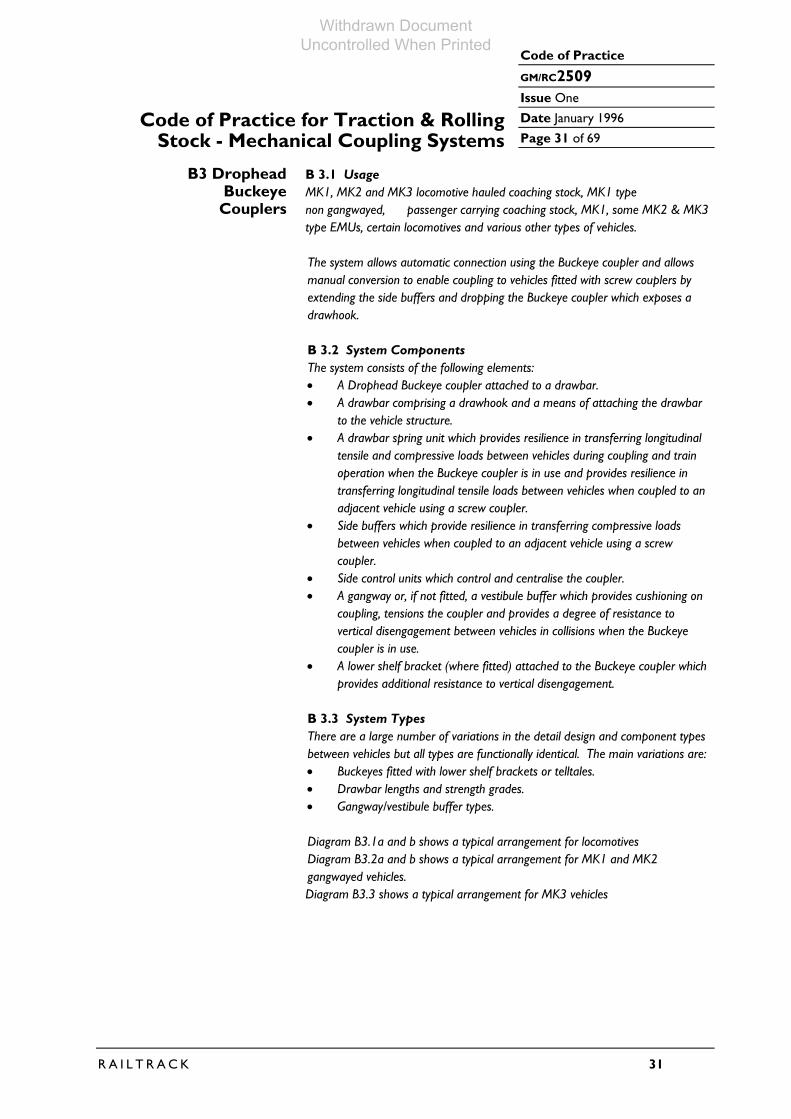
B 2.4.3 Drawbar Spring Unit Drawbar spring units consist of a stack of rubber elements with steel dividing plates. B 2.4.4 Buffers Buffers are generally 520mm projection hydraulic/gas type. Buffer heads are profiled in the vertical and horizontal planes to minimise offset loading during curve negotiation. Buffer head shapes and sizes are selected to minimise the risk of lateral or vertical buffer locking (or combinations thereof) during inter-vehicle movement generated by vehicle height differentials, dynamic movements and curve negotiation. B 2.5 System Standards Specific requirements for each type of freight vehicle are detailed by the vehicle specification. Guidance notes are defined in reference [27]. The geometry between drawbars, couplers and buffer face and the geometry of the coupling are standard as typically shown in Diagram B.2.
Withdrawn Document Uncontrolled When Printed

Code of Practice
GM/RC2509
Issue One
Date January 1996 Page 30 of 69
30 R A I L T R A C K
Code of Practice for Traction & Rolling Stock - Mechanical Coupling Systems
Diagram B.2 : Typical Instanter Coupler Arrangement (Dimensions Nominal)
1714
BU
FFE
RS
CE
NTR
ES
RA
IL L
EV
EL
457
1054 CENTRE OF BUFFER
VE
RTI
CA
L S
UP
PO
RT
279
CENTRE OF DRAWHOOK EYE
1054
DR
AW
BA
R S
PR
ING
UN
IT
DR
AW
BA
R
114
VE
H.
0O0O
C L
NO
TES
1. B
ased
On
45t H
oppe
r Min
eral
Wag
on
2. R
efer
ence
Drg
s
- Arr
ange
men
t F-S
-123
38
- Ins
tant
er C
oupl
ing
SW
/SW
/116
5
- Dra
wba
r STD
140
8
- Dra
wba
r Spr
ing
Uni
t (S
ee A
rran
gem
ent)
- Buf
fers
SW
/DE
/466
40 (O
LEO
CO
DE
OP
13)
DIA
GR
AM
B 2
: TY
PIC
AL
INS
TAN
TER
CO
UP
LER
AR
RA
NG
EM
EN
T
Withdrawn Document Uncontrolled When Printed
Code of Practice
GM/RC2509
Issue One
Date January 1996
Page 31 of 69
R A I L T R A C K 31
Code of Practice for Traction & RollingStock - Mechanical Coupling Systems
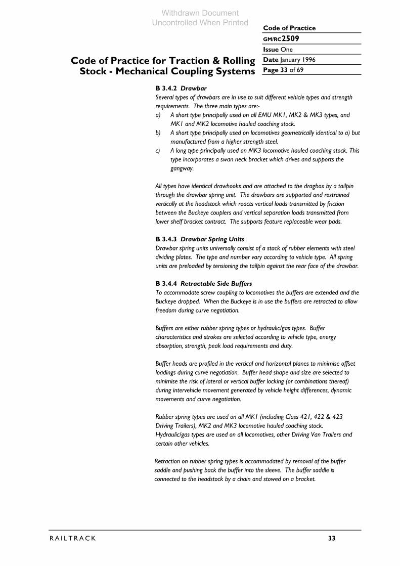
B3 Drophead B 3.1 Usage Buckeye MK1, MK2 and MK3 locomotive hauled coaching stock, MK1 type Couplers non gangwayed, passenger carrying coaching stock, MK1, some MK2 & MK3
type EMUs, certain locomotives and various other types of vehicles. The system allows automatic connection using the Buckeye coupler and allows manual conversion to enable coupling to vehicles fitted with screw couplers by extending the side buffers and dropping the Buckeye coupler which exposes a drawhook. B 3.2 System Components The system consists of the following elements: • A Drophead Buckeye coupler attached to a drawbar. • A drawbar comprising a drawhook and a means of attaching the drawbar
to the vehicle structure. • A drawbar spring unit which provides resilience in transferring longitudinal
tensile and compressive loads between vehicles during coupling and train operation when the Buckeye coupler is in use and provides resilience in transferring longitudinal tensile loads between vehicles when coupled to an adjacent vehicle using a screw coupler.
• Side buffers which provide resilience in transferring compressive loads between vehicles when coupled to an adjacent vehicle using a screw coupler.
• Side control units which control and centralise the coupler. • A gangway or, if not fitted, a vestibule buffer which provides cushioning on
coupling, tensions the coupler and provides a degree of resistance to vertical disengagement between vehicles in collisions when the Buckeye coupler is in use.
• A lower shelf bracket (where fitted) attached to the Buckeye coupler which provides additional resistance to vertical disengagement.
B 3.3 System Types There are a large number of variations in the detail design and component types between vehicles but all types are functionally identical. The main variations are: • Buckeyes fitted with lower shelf brackets or telltales. • Drawbar lengths and strength grades. • Gangway/vestibule buffer types. Diagram B3.1a and b shows a typical arrangement for locomotives Diagram B3.2a and b shows a typical arrangement for MK1 and MK2 gangwayed vehicles.
Diagram B3.3 shows a typical arrangement for MK3 vehicles
Withdrawn Document Uncontrolled When Printed

Code of Practice
GM/RC2509
Issue One
Date January 1996 Page 32 of 69
32 R A I L T R A C K
Code of Practice for Traction & Rolling Stock - Mechanical Coupling Systems
B 3.4 System Description B 3.4.1 Drophead Buckeye The coupler is mounted to allow freedom to pivot (via the drawbar) in the horizontal plane to enable negotiation of horizontal curves, whilst being supported and restrained vertically. Vertical differential movements between vehicles are accommodated by sliding between couplers and pitch and roll movements are accommodated by clearances between the coupler heads.
The coupler is attached to the drawbar by a pin and split pin which allows the coupler to pivot down when screw coupling to an adjacent vehicle is required. When the Buckeye is required it is manually lifted and supported by a special pin with a toggle end which passes through the coupler body and drawhook eye. This pin is permanently attached to the headstock by a chain. Coupling is automatically achieved by moving one vehicle towards the other at slow speed. To achieve coupling both buckeyes must be in the up position and at least one knuckle is required to be in the open position (the normal position after uncoupling). If the knuckle is in the closed position it is opened by operating the coupler release chain. Coupling on curves (within limits) is facilitated by gathering arms on the coupler heads, but on smaller radii curves it may be necessary to open both knuckles. Uncoupling is achieved by operating the coupler release chain on either vehicle. The release chain is always fitted on the right hand side of the vehicle (viewed on the vehicle end) and extends via guide tubes to the outside of the vehicle. Confirmation of coupling is achieved by a draw test, however EMU trains which regularly couple in service are fitted with a tell tale which, when in the dropped position, indicates successful coupling. The majority of ex-InterCity vehicles with Buckeye couplers have been fitted with lower shelf brackets to provide additional vertical resistance to vehicle separation in derailments to that provided by the gangway or vestibule buffer. The bracket, which is attached to an extended knuckle pin allows for vertical movements between vehicles encountered in normal service, but engages the knuckle of the adjacent coupler when gross vertical misalignment occurs. The engagement is designed to occur coincidentally (as far as practicable) with engagement between the top of the coupler and the underside of the gangway or vestibule buffer. The separation forces are transmitted through the gangway/vestibule buffer and the drawbar back to the vehicle structure.
Withdrawn Document Uncontrolled When Printed
Code of Practice
GM/RC2509
Issue One
Date January 1996
Page 33 of 69
R A I L T R A C K 33
Code of Practice for Traction & RollingStock - Mechanical Coupling Systems
B 3.4.2 Drawbar Several types of drawbars are in use to suit different vehicle types and strength requirements. The three main types are:- a) A short type principally used on all EMU MK1, MK2 & MK3 types, and
MK1 and MK2 locomotive hauled coaching stock. b) A short type principally used on locomotives geometrically identical to a) but
manufactured from a higher strength steel. c) A long type principally used on MK3 locomotive hauled coaching stock. This
type incorporates a swan neck bracket which drives and supports the gangway.
All types have identical drawhooks and are attached to the dragbox by a tailpin through the drawbar spring unit. The drawbars are supported and restrained vertically at the headstock which reacts vertical loads transmitted by friction between the Buckeye couplers and vertical separation loads transmitted from lower shelf bracket contract. The supports feature replaceable wear pads. B 3.4.3 Drawbar Spring Units Drawbar spring units universally consist of a stack of rubber elements with steel dividing plates. The type and number vary according to vehicle type. All spring units are preloaded by tensioning the tailpin against the rear face of the drawbar. B 3.4.4 Retractable Side Buffers To accommodate screw coupling to locomotives the buffers are extended and the Buckeye dropped. When the Buckeye is in use the buffers are retracted to allow freedom during curve negotiation. Buffers are either rubber spring types or hydraulic/gas types. Buffer characteristics and strokes are selected according to vehicle type, energy absorption, strength, peak load requirements and duty. Buffer heads are profiled in the vertical and horizontal planes to minimise offset loadings during curve negotiation. Buffer head shape and size are selected to minimise the risk of lateral or vertical buffer locking (or combinations thereof) during intervehicle movement generated by vehicle height differences, dynamic movements and curve negotiation. Rubber spring types are used on all MK1 (including Class 421, 422 & 423 Driving Trailers), MK2 and MK3 locomotive hauled coaching stock. Hydraulic/gas types are used on all locomotives, other Driving Van Trailers and certain other vehicles.
Retraction on rubber spring types is accommodated by removal of the buffer
saddle and pushing back the buffer into the sleeve. The buffer saddle is connected to the headstock by a chain and stowed on a bracket.
Withdrawn Document Uncontrolled When Printed
Code of Practice
GM/RC2509
Issue One
Date January 1996 Page 34 of 69
34 R A I L T R A C K
Code of Practice for Traction & Rolling Stock - Mechanical Coupling Systems
Retraction on hydraulic/gas types is accommodated by removal of a pin, rotating (though 90°) and pushing back the buffer into the stock followed by re-insertion of the pin. B 3.4.5 Side Control Units Side control units are generally rubber springs but certain older vehicles are fitted with coil spring types. As well as centralising the coupler the units provide rotational stiffness about the drawbar pivot in the horizontal plane and therefore contribute to the transverse intervehicle stiffness resisting lateral separation of vehicles during curve negotiation. The units are therefore influential in limiting the risk of buffer locking with locomotives not fitted with Buckeye couplers during operation through reverse curves. Due to differences between former BR and UIC requirements checks should be made to ensure that each of the elements and the materials from which they are manufactured are compatible with the specific arrangement. B 3.4.6 Gangways and Vestibule Buffers Gangways form part of the coupling system as they provide cushioning on coupling, tension the Buckeye coupler and as described in B.3.4.1 provide vertical disengagement resistance. Vehicles fitted with Buckeye couplers which do not have gangways are fitted with vestibule buffers which resemble the lower part of a MK1/MK2 gangway. In these cases the vestibule buffer compresses and controls the adjacent gangway (or vestibule buffer) and minimises the risk of gangway/vestibule buffer locking with side buffers during propelling movements through reverse curves. Gangways for MK1 and MK2 are body mounted via the vestibule buffer spring units. The faceplates are proud of the Buckeye coupling plane and are compressed during coupling against preloaded coil springs. The spring units allow further compressions to accommodate movements between vehicles during curve negotiation and compressive loadings on the drawgear. The units therefore allow the gangway faceplate to rotate in both the horizontal and vertical planes. Gangways for MK3 vehicles function in a similar manner but the gangway is mounted and driven off the coupler and faceplate compressions are controlled by a shear unit which comprises a number of rubber shear elements. Horizontal and vertical faceplate rotation is controlled by a spherical rubber bush mounted off the shear unit. Both types are compatible with each other and the spring characteristics are similar, ensuring faceplates are equally compressed after coupling. Vestibule buffers fitted to locomotives and certain other vehicles feature extensions to the upper surface of the buffers. These extensions prevent vestibule buffer locking when vehicles negotiate reverse curves and are simultaneously subject to vertical movements between vehicles which exceed the vestibule buffer face depth across the centre section.
Withdrawn Document Uncontrolled When Printed

Code of Practice
GM/RC2509
Issue One
Date January 1996
Page 35 of 69
R A I L T R A C K 35
Code of Practice for Traction & RollingStock - Mechanical Coupling Systems
Both gangways and vestibule buffers are lined with replaceable anti-friction material on the right hand side (viewed looking on the vehicle) to reduce friction between the sliding surfaces. B 3.5 System Standards Whilst there are several types of MK1 and MK2 vehicle gangways and vestibule buffers, side buffers and drawbars, the geometric relationships between drawhooks, gangways vestibule buffers and side buffers are largely identical as shown in diagrams, B3.1a, B3.1b, B3.2a, B3.2b and B3.3.
Withdrawn Document Uncontrolled When Printed

Code of Practice
GM/RC2509
Issue One
Date January 1996 Page 36 of 69
36 R A I L T R A C K
Code of Practice for Traction & Rolling Stock - Mechanical Coupling Systems
Diagram B 3.1a : Typical Drophead Buckeye Arrangement For Locomotives - Buckeye Down And Buffers Extended For Coupling With Screw Coupler (Dimensions Nominal)
560
1727
BU
FFER
CE
NTR
ES
RA
IL L
EV
EL
1414
114
DR
AW
BA
R S
PR
ING
UN
IT
VEST
IBU
LE B
UFF
ERS
PR
ING
PIVO
T PI
NV
EH
.C L
SID
E C
ON
TRO
L U
NIT
DR
AW
PIN
VE
STI
BU
LE B
UFF
ER
UN
IT
460
1054
CENTRE OF BUFFERS
1020CENTRE OF DRAWHOOK EYE
398
VE
RTI
CA
LS
UP
PO
RT
LOW
ER
SH
ELF
BR
CK
ET
(WH
ER
E F
ITTE
D)
NO
TES
1. B
ased
On
CI9
1 N
o. 1
End
2. R
efer
ence
Drg
s
- Arr
ange
men
t 817
0465
- Buc
keye
Cou
pler
B1-
A0-
9011
410
B1-
A0-
9022
276
(with
LS
B)
- Dra
wba
r 901
2629
- Dra
wba
r Spr
ing
Uni
t (S
ee A
rran
gem
ent)
- Sid
e C
ontro
l Uni
t 819
0455
- Ves
tibul
e B
uffe
r Uni
t 819
0449
- Buf
fers
Ole
o O
P68
ZL
DIA
GR
AM
B 3
.1a
: TY
PIC
AL
DR
OP
HE
AD
BU
CK
EY
E A
RR
AN
GE
ME
NT
FOR
LOC
OM
OTI
VES
- B
UC
KEY
E D
OW
N A
ND
BU
FFE
RS
EX
TEN
DE
D F
OR
CO
UP
LIN
G W
ITH
SC
RE
W C
OU
PLE
R
Withdrawn Document Uncontrolled When Printed

Code of Practice
GM/RC2509
Issue One
Date January 1996
Page 37 of 69
R A I L T R A C K 37
Code of Practice for Traction & RollingStock - Mechanical Coupling Systems
Diagram B 3.1b : Typical Drophead Buckeye Arrangement For Locomotives - Buckeye Up And Buffers Retracted For Coupling To Vehicles With Buckeye Couplers
560
1727
BU
FFE
R C
EN
TRE
S
1414
DR
AW
BA
R S
PR
ING
UN
IT
VE
STI
BU
LE B
UFF
ER
SP
RIN
G U
NIT
PIV
OT
PIN
VE
H.
C LS
IDE
CO
NTR
OL
UN
ITD
RA
W P
IN
VE
STU
BU
LE B
UFF
ER
UN
IT
460
1054CENTRE OF BUFFERS
VE
RTI
CA
LS
UP
PO
RT
LOW
ER
SH
ELF
BR
AC
KE
T(W
HE
RE
FIT
TED
)
NO
TES
1. B
ased
On
CI9
1 N
o. 1
End
2. R
efer
ence
Drg
s
- Arra
ngem
ent 8
1704
65
- Buc
keye
Cou
pler
B1-
A0-
9011
410
B1-
A0-
9022
276
(with
LS
B)
- Dra
wba
r 901
2629
- Dra
wba
r Spr
ing
Uni
t (S
ee A
rrang
emen
t)
- Sid
e C
ontro
l Uni
t 819
0455
- Ves
tibul
e B
uffe
r Uni
t 819
0449
- Buf
fers
Ole
o O
P68
ZL
DIA
GR
AM
B 3
.1b
: TY
PIC
AL
DR
OP
HE
AD
BU
CK
EY
E A
RR
AN
GE
ME
NT
FO
R L
OC
OM
OTI
VE
S -
BU
CK
EY
E D
OW
N A
ND
BU
FFE
RS
RE
TRA
CTE
DFO
R C
OU
PLI
NG
TO
VE
HIC
LES
WIT
H B
UC
KE
YE
CO
UP
LER
S
CENTRE OF COUPLER
997
114
BU
CK
EY
EC
OU
PLI
NG
PLA
NE
CO
UP
LER
SU
PP
OR
T P
IN
Withdrawn Document Uncontrolled When Printed
Code of Practice
GM/RC2509
Issue One
Date January 1996 Page 38 of 69
38 R A I L T R A C K
Code of Practice for Traction & Rolling Stock - Mechanical Coupling Systems
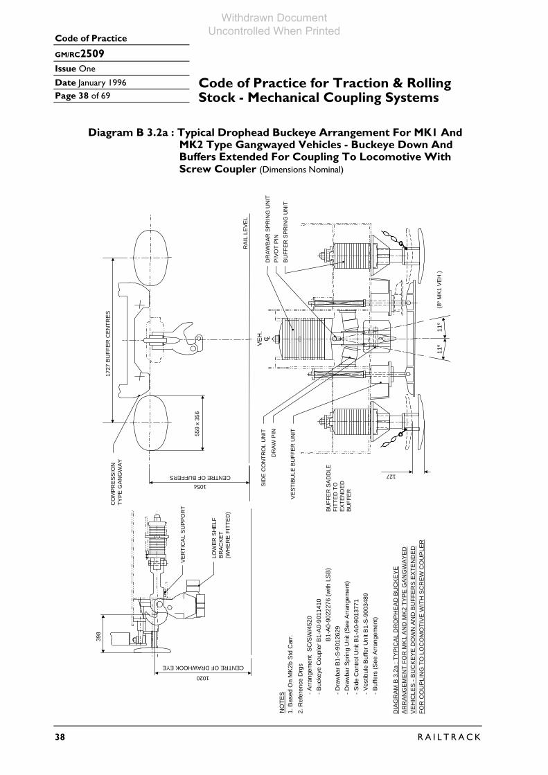
Diagram B 3.2a : Typical Drophead Buckeye Arrangement For MK1 And
MK2 Type Gangwayed Vehicles - Buckeye Down And Buffers Extended For Coupling To Locomotive With Screw Coupler (Dimensions Nominal)
1727
BU
FFE
R C
EN
TRE
S
559
x 35
6
CO
MP
RE
SS
ION
TYP
E G
AN
GW
AY
RA
IL L
EV
EL
CENTRE OF BUFFERS1054
LOW
ER
SH
ELF
BR
AC
KE
T(W
HE
RE
FIT
TED
)
VE
RTI
CA
L S
UP
PO
RT
1020
CENTRE OF DRAWHOOK EYE39
8
SID
E C
ON
TRO
L U
NIT
DR
AW
PIN
VE
STI
BU
LE B
UFF
ER
UN
IT
11o
11o
VE
H.
C LD
RA
WB
AR
SP
RIN
G U
NIT
PIV
OT
PIN
BU
FFE
R S
PR
ING
UN
IT
(8o M
K1
VE
H.)
127
BU
FFE
R S
AD
DLE
FITT
ED
TO
EX
TEN
DE
DB
UFF
ER
NO
TES
1. B
ased
On
MK
2b S
td C
arr.
2. R
efer
ence
Drg
s- A
rran
gem
ent
SC
/SW
/452
0- B
ucke
ye C
oupl
er B
1-A
0-90
1141
0
- Dra
wba
r B1-
S-9
0126
29- D
raw
bar S
prin
g U
nit (
See
Arr
ange
men
t)
DIA
GR
AM
B 3
.2a
: TY
PIC
AL
DR
OP
HE
AD
BU
CK
EY
EA
RR
AN
GE
ME
NT
FOR
MK
1 A
ND
MK
2 TY
PE
GA
NG
WA
YE
DV
EH
ICLE
S -
BU
CK
EY
E D
OW
N A
ND
BU
FFE
RS
EX
TEN
DE
DFO
R C
OU
PLI
NG
TO
LO
CO
MO
TIV
E W
ITH
SC
RE
W C
OU
PLE
R
- Sid
e C
ontro
l Uni
t B1-
A0-
9013
771
B1-
A0-
9022
276
(with
LS
B)
- Ves
tibul
e B
uffe
r Uni
t B1-
S-9
0034
89- B
uffe
rs (S
ee A
rran
gem
ent)
Withdrawn Document Uncontrolled When Printed

Code of Practice
GM/RC2509
Issue One
Date January 1996
Page 39 of 69
R A I L T R A C K 39
Code of Practice for Traction & RollingStock - Mechanical Coupling Systems
Diagram B 3.2b : Typical Drophead Buckeye Arrangement For MK1 And MK2 Type Gangwayed Vehicles - Buckeye Up And Buffers Retracted For Coupling To Vehicles With Buckeye Couplers (Dimensions Nominal)
NO
TES
1. B
ased
On
MK
2b S
td C
arr.
2. R
efer
ence
Drg
s- A
rran
gem
ent
SC
/SW
/452
0- B
ucke
ye C
oupl
er B
1-A
0-90
1141
0
- Dra
wba
r B1-
S-9
0126
29- D
raw
bar S
prin
g U
nit (
See
Arr
ange
men
t)
DIA
GR
AM
B 3
.2b
: TY
PIC
AL
DR
OP
HE
AD
BU
CK
EY
EA
RR
AN
GE
ME
NT
FOR
MK
1 A
ND
MK
2 TY
PE
GA
NG
WA
YE
DV
EH
ICLE
S -
BU
CK
EY
E U
P A
ND
BU
FFE
RS
RE
TRA
CTE
DFO
R C
OU
PLI
NG
TO
VE
HIC
LES
WIT
H B
UC
KE
YE
CO
UP
LER
S
- Sid
e C
ontro
l Uni
t B1-
A0-
9013
771
B1-
A0-
9022
276
(with
LS
B)
- Ves
tibul
e B
uffe
r Uni
t B1-
S-9
0034
89- B
uffe
rs (S
ee A
rran
gem
ent)
1727
BU
FFER
CEN
TRES
559
x 35
6
LOW
ER S
HEL
F BR
ACKE
T(W
HER
E FI
TTED
)
VER
TIC
AL S
UPP
OR
T
CENTRE OF COUPLER
997
CO
MPR
ESSI
ON
TYPE
GAN
GW
AY
CENTRE OF BUFFERS
1054SI
DE
CO
NTR
OL
UN
IT
DR
AW P
IN
CO
UPL
ER S
UPP
OR
T PI
N
BUFF
ERSA
DD
LE(S
TOW
ED)
AUTO
-CO
UPL
ERR
ELEA
SE C
HAI
N
RAI
L LE
VEL
127
BUC
KEYE
CO
UPL
ING
PLAN
E
11o
11o
VE
H.
C LD
RAW
BAR
SPR
ING
UN
IT
PIVO
T PI
N
BUFF
ER S
PRIN
G U
NIT
(8o M
K1 V
EH.)
Withdrawn Document Uncontrolled When Printed

Code of Practice
GM/RC2509
Issue One
Date January 1996 Page 40 of 69
40 R A I L T R A C K
Code of Practice for Traction & Rolling Stock - Mechanical Coupling Systems
Diagram B.3.3 : Typical Drophead Buckeye Arrangement For MK3 Gangwayed Vehicles - Buckeye Down And Buffers Extended For Coupling To Locomotive With Screw Coupler (Dimensions Nominal)
RAI
L LE
VEL
1727
BU
FFER
CEN
TRES
CO
MPR
ESSI
ON
TYPE
GAN
GW
AY
1054CENTRE OF BUFFERS
559
x 35
6VE
RTI
CAL
SU
PPO
RT
LOW
ER S
HEL
F BR
ACKE
T(W
HER
E FI
TTED
)
GAN
GW
AY D
RIV
E
398
1020
CENTRE OF DRAWHOOK EYE
DR
AWBA
R S
PRIN
G U
NIT
PIVO
T PI
N
BUFF
ER S
PRIN
G U
NIT
SID
E C
ON
TRO
L U
NIT
DR
AW B
AR
BUFF
ER S
ADD
LEFI
TTED
TO
EXTE
ND
EDBU
FFER
127
VEH
.C L
10o
10o
NO
TES
1. B
ased
On
MK3
Loc
o H
aule
d C
arr.
2. R
efer
ence
Drg
s- A
rrang
emen
t C
-S-8
892
- Buc
keye
Cou
pler
B1-
A0-9
0114
10
- Dra
who
ok (
C-S
-111
25)
- Dra
who
ok S
prin
g U
nit (
See
Arra
ngem
ent)
DIA
GR
AM B
3.3
: TY
PIC
AL D
RO
PHEA
D B
UC
KEYE
AR
RAN
GEM
ENT
FOR
MK3
TYP
E G
ANG
WAY
ED V
EHIC
LES
- BU
CKE
YE D
OW
NAN
D B
UFF
ERS
EXTE
ND
ED F
OR
CO
UPL
ING
TO
LO
CO
MO
TIVE
WIT
H S
CR
EW C
OU
PLER
- Sid
e C
ontro
l Uni
t C-A
0-49
47
B1-A
0-90
2227
6 (w
ith L
SB)
- Arrg
mt O
f Gan
gway
C-S
-122
87 &
B1-
S-90
0482
7- B
uffe
rs (S
ee A
rrang
emen
t)
Withdrawn Document Uncontrolled When Printed

Code of Practice
GM/RC2509
Issue One
Date January 1996
Page 41 of 69
R A I L T R A C K 41
Code of Practice for Traction & RollingStock - Mechanical Coupling Systems
B4 Alliance Couplers B 4.1 Usage Intermediate ends of MK1 and some MK2 type EMU stock(Cl310 & 312) and
intermediate ends of MK3 HST trainsets.
The system allows automatic connection of vehicles and in principle is similar to the Buckeye coupler system without the facility for conversion to allow connection to locomotives fitted with a screw coupler. B 4.2 System Components The system consists of the following elements:- • An Alliance Coupler, integral with a drawbar and a means of attaching the
drawbar to the vehicle structure. • A drawbar spring unit which provides resilience in transferring longitudinal
and compressive loads between vehicles during coupling and train operation.
• Side control units which control and centralise the coupler. • A gangway which provides cushioning on coupling, tensions the coupler and
provides a degree of resistance to vertical disengagement between vehicles in collisions.
• A lower shelf bracket (where fitted) attached to the Alliance Coupler which provides additional resistance to vertical disengagement.
B 4.3 System Types Designs are similar for all types, the main variations being:- * Couplers fitted with lower shelf brackets. * Drawbar lengths. * Gangway types.
Diagram B4.1 shows a typical arrangement for a MK1 EMU type. B 4.4 System Description B 4.4.1 Alliance Coupler The Alliance coupler head is integral with the drawbar. The head profile is a 10A AAR contour. Three types are in use as follows: a) A short length coupler used on an MK1 EMU types. b) A medium length coupler used on the non cab end of HST power cars. c) A long length coupler used on MK3 HST coaches. The coupler is mounted to allow freedom to pivot in the horizontal plane to enable negotiation of horizontal curves, whilst being supported and restrained vertically. Vertical differential movements between vehicles are accommodated by sliding between couplers and pitch and roll movements are accommodated by clearances between the coupler heads.
Withdrawn Document Uncontrolled When Printed

Code of Practice
GM/RC2509
Issue One
Date January 1996 Page 42 of 69
42 R A I L T R A C K
Code of Practice for Traction & Rolling Stock - Mechanical Coupling Systems
Coupling is achieved automatically by moving one vehicle towards the other at slow speed. To achieve coupling at least one knuckle is required to be in the open position (the normal position after uncoupling). If the knuckle is in the closed position it is opened by use of a shunting hook (or by operating the coupler release chain where fitted). It should be noted that for most vehicles the coupler release chain has been removed for safety reasons. Coupling on curves (within limits) is facilitated by gathering arms on the coupler body, but on smaller radius curves it may be necessary to open both knuckles. Uncoupling on MK1 EMU types is achieved by use of a shunting hook (or by operating the coupler release chain on either vehicle where fitted). The release chain, if fitted, is always fitted on the right hand side of the vehicle (viewed on the vehicles ends) and extends via guide tubes to the outside of the vehicle. Uncoupling a MK3 type is achieved by release of a retaining pin and operation of the release lever using an uncoupling bar. Confirmation of coupling is achieved by a draw test. All MK3 HST vehicles have been fitted with lower shelf brackets to provide additional vertical resistance to vehicle separation in derailments to that provided by the gangway. The bracket which is attached to an extended knuckle pin allows for vertical movements between vehicles encountered in normal service, but engages the knuckle of the adjacent coupler when gross vertical misalignment occurs. The engagement is designed to occur coincidentally (as far as practicable) with engagement between the top of the coupler and the underside of the gangway. The separation forces are transmitted through the gangway buffer and the Alliance coupler back to the vehicle structure. B 4.4.2 Drawbar Spring Units Drawbar spring units are universally a stack of rubber elements with steel dividing plates. The type and number vary according to vehicle type. All spring units are preloaded by tensioning the tailpin against the rear face of the drawbar. B 4.4.3 Side Control Units Side control units generally consist of rubber springs but certain older vehicles are fitted with coil spring types. As well as centralising the coupler the units provide rotational stiffness about the drawbar pivot in the horizontal plane and therefore contribute to the transverse intervehicle stiffness resisting lateral separation of vehicles during curve negotiation. B 4.4.4 Gangways Gangways form part of the coupling system as they provide cushioning on coupling, tension the couplers and as described in 4.4.1 provide vertical disengagement resistance.
Withdrawn Document Uncontrolled When Printed
Code of Practice
GM/RC2509
Issue One
Date January 1996
Page 43 of 69
R A I L T R A C K 43
Code of Practice for Traction & RollingStock - Mechanical Coupling Systems
Gangways for MK1 EMU type are body mounted via the vestibule buffer spring units. The faceplates are proud of the Alliance coupling plane and are compressed during coupling against preloaded coil springs. The spring units allow further compressions to accommodate movements between vehicles during curve negotiation and compressive loadings on the drawgear. The units therefore allow the gangway faceplate to rotate in both the horizontal and vertical planes. Gangways for MK3 HST vehicles function in a similar manner but the gangway is mounted and driven off the coupler. Faceplate compressions are controlled by a shear unit which comprises of a number of rubber shear elements. Horizontal and vertical faceplate rotation is controlled by a spherical rubber bush mounted off the shear unit.
Gangways are lined with replaceable anti-friction material on the right hand side (viewed looking at the vehicle) to reduce friction between the sliding surfaces.
B 4.4.5 System Standards The Alliance coupler centre height is 997mm ARL on all types of vehicle fitted.
Withdrawn Document Uncontrolled When Printed
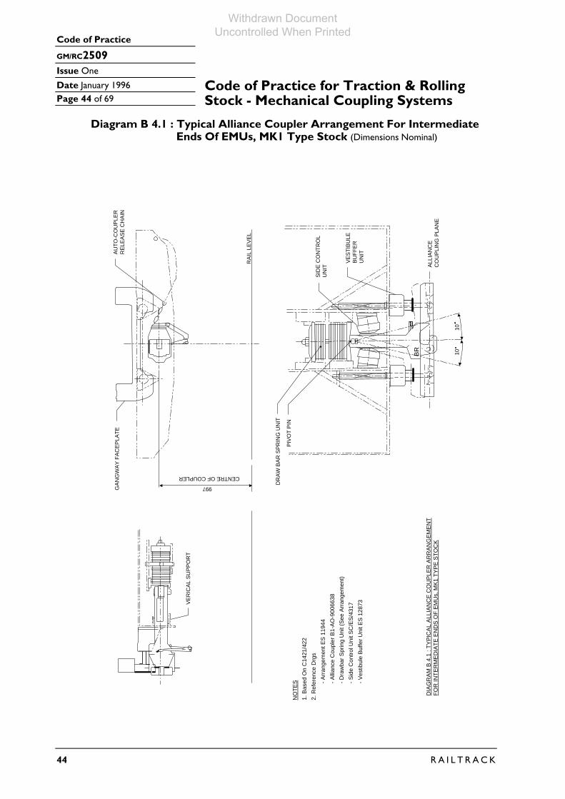
Code of Practice
GM/RC2509
Issue One
Date January 1996 Page 44 of 69
44 R A I L T R A C K
Code of Practice for Traction & Rolling Stock - Mechanical Coupling Systems
Diagram B 4.1 : Typical Alliance Coupler Arrangement For Intermediate Ends Of EMUs, MK1 Type Stock (Dimensions Nominal)
BR
1010
ALLI
ANC
EC
OU
PLIN
G P
LAN
E
VEST
IBU
LEB
UFF
ER
UN
IT
SID
E C
ON
TRO
LU
NIT
DR
AW B
AR S
PRIN
G U
NIT
PIVO
T PI
N
GAN
GW
AY F
ACEP
LATE
CENTRE OF COUPLER
997
VER
ICAL
SU
PPO
RT
NO
TES
1. B
ased
On
C14
21/4
222.
Ref
eren
ce D
rgs
- Arr
ange
men
t ES
119
44- A
llian
ce C
oupl
er B
1-A
O-9
0066
38- D
raw
bar S
prin
g U
nit (
See
Arr
ange
men
t)- S
ide
Con
trol U
nit S
C/E
S/4
317
- Ves
tibul
e B
uffe
r Uni
t ES
128
73
DIA
GR
AM
B 4
.1 :
TYP
ICA
L A
LLIA
NC
E C
OU
PLE
R A
RR
AN
GE
ME
NT
FOR
INTE
RM
ED
IATE
EN
DS
OF
EM
Us,
MK
1 TY
PE
STO
CK
AUTO
-CO
UPL
ERR
ELEA
SE C
HAI
N
RAI
L LE
VEL
Withdrawn Document Uncontrolled When Printed

Code of Practice
GM/RC2509
Issue One
Date January 1996
Page 45 of 69
R A I L T R A C K 45
Code of Practice for Traction & RollingStock - Mechanical Coupling Systems
B5 BSI Couplers B 5.1 Usage Unit ends and some intermediate ends of second generation DMUs. The system allows automatic connection of vehicles. B 5.2 System Components The system consists of the following elements:- • A BSI coupler head integral with a drawbar and a means of attaching the
drawbar to the structure. • A drawbar spring unit which provides resilience in transferring longitudinal
tensile and compressive loads between vehicles during coupling and train operation.
• Side control units which control and centralise the coupler. • A coupler suspension unit to support the coupler during coupling. B 5.3 System Types All vehicles are generally similar and compatible with each other. However, only couplers used on unit ends have an electrical head to allow automatic connection of electrical connections during coupling. Diagram B5 shows a typical arrangement. B 5.4 System Description B 5.4.1 BSI Coupler The BSI coupler head is integral with the drawbar. The coupler head type is CK2, and all feature an integral pneumatic connection. Types used on vehicle ends fitted with gangways feature an attachment to drive the gangway. When the couplers are connected there is no freedom of movement between the coupler heads and all relative vertical transverse and roll movements between vehicles are accommodated at the drawbar pivot. Coupling is achieved automatically by moving one vehicle towards the other at slow speed. Couplings on curves (within limits) and between vehicles at different heights is accommodated by alignment wings on the coupler head. Coupling and uncoupling on unit ends is by couple/uncouple buttons in the driver’s cab which also isolate and connect the electrical and pneumatic supplies between vehicles. Confirmation of coupling can be obtained by a draw test and an interlock in the brake continuity wire. Automatic uncoupling is accommodated by coupler mounted pneumatic equipment. Manual uncoupling is available by the use of an uncoupling bar. Intermediate vehicles can only be uncoupled manually. Prevention of overriding or gross transverse separation between vehicles during collisions and derailments is provided by the coupler engaging with the aperture in the headlock or with the coupler suspension units.
Withdrawn Document Uncontrolled When Printed

Code of Practice
GM/RC2509
Issue One
Date January 1996 Page 46 of 69
46 R A I L T R A C K
Code of Practice for Traction & Rolling Stock - Mechanical Coupling Systems
B 5.4.2 Drawbar Spring Units Drawbar spring units universally consist of a stack of rubber elements with steel dividing plates. All spring units are preloaded by tensioning the tailpin. B 5.4.3 Side Control Units Side control units are generally rubber springs. As well as centralising the coupler the units provide rotational stiffness about the drawbar pivot in the horizontal plane and therefore contribute to the transverse inter-vehicle stiffness resisting lateral separation of vehicles during curve negotiation. B 5.4.4 Coupler Suspension Units All types are fitted with equipment which supports the coupler at nominal height during coupling but allows freedom for connected couplers to accommodate intervehicle movements. Suspension units comprise a coil spring loaded plank supporting the coupler at the rear of the coupler head. The plank height is variable to allow adjustment of the coupler height. B 5.5 System Standards Specific requirements for each type of vehicle are defined in the vehicle specification. Nominal coupler height above rail level is 925 mm for all types of DMU fitted with BSI couplers.
Withdrawn Document Uncontrolled When Printed

Code of Practice
GM/RC2509
Issue One
Date January 1996
Page 47 of 69
R A I L T R A C K 47
Code of Practice for Traction & RollingStock - Mechanical Coupling Systems
Diagram B 5 : Typical BSI Coupler Arrangement For DMU (Dimensions Nominal)
AIR
CO
UP
ING
RA
IL L
EV
EL
DR
AW
BA
R S
PR
ING
UN
IT
PIV
OT
PIN
VE
H.
C L
11.5
11.5
CO
UP
ING
PLA
NE
DR
AW
BA
R R
OTA
TIO
N S
TOP
S
SID
E C
ON
TRO
L U
NIT
S
3.64
CENTRE OF COUPLER925
CO
UP
LER
SU
SP
EN
SIO
N U
NIT
ELE
CTR
ICA
L H
EA
D
NO
TES
1. B
ased
On
C11
58 (C
ab E
nd)
2. R
efer
ence
Drg
s- A
rran
gem
ent 8
0088
80 &
800
8881
- Aut
omat
ic C
oupl
er 8
0088
82- D
raw
bar S
prin
g U
nit (
See
Arr
ange
men
t)- S
ide
Con
trol U
nit 8
0088
89- C
oupl
er S
uspe
nsio
n U
nit 8
0088
90
DIA
GR
AM
B 5
: TY
PIC
AL
BS
I CO
UP
LER
AR
RA
NG
EM
EN
T FO
R D
MU
Withdrawn Document Uncontrolled When Printed

Code of Practice
GM/RC2509
Issue One
Date January 1996 Page 48 of 69
48 R A I L T R A C K
Code of Practice for Traction & Rolling Stock - Mechanical Coupling Systems
B6 TightlockB 6.1 Usage
Couplers Unit (cab) ends of EMUs and MK4 Coaching Stock. The system allows automatic connection of vehicles.
B 6.2 System Components The System consists of the following elements:- • A Tightlock coupler head integral with the drawbar and a means of attaching
the drawbar to the structure. • A drawbar spring unit or an energy absorption unit which provides resilience
in transferring longitudinal tensile and compressive loads between vehicles during coupling and train operation.
• Side control units which control and centralise the coupler. • A coupler suspension unit to support the coupler during coupling. B 6.3 System Types Two separate system types are in use as follows: a) EMU type, which allows remote control of coupling and uncoupling from
the driver’s cab. This type features an electrical and pneumatic head which is attached to the base of the coupler to allow automatic connection of electrical and air connections during coupling. All EMU types are compatible with each other, but components and configuration vary according to vehicle type, manufacturer and date of build.
b) MK4 coach type, where uncoupling is performed manually from the
trackside. This type does not carry any electrical or pneumatic connections. The two types are not designed to be compatible with each other and cannot physically couple by virtue of differences in installed heights. Diagram B6.1 shows a typical arrangement for MK4 coaches. Diagram B6.2 shows a typical arrangement for an EMU. Diagram B6.3 shows a typical arrangement for an EMU with high performance energy absorption. B 6.4 System Description B 6.4.1 Tightlock Coupler The Tightlock coupler head is integral with the drawbar. The type of head used is specific to BR requirements, other types of Tightlock heads may therefore not be compatible. The type used on MK4 coaches does not have a spring loaded knuckle to keep the knuckle open after release and is therefore unsuitable for use on EMU vehicles.
Withdrawn Document Uncontrolled When Printed

Code of Practice
GM/RC2509
Issue One
Date January 1996
Page 49 of 69
R A I L T R A C K 49
Code of Practice for Traction & RollingStock - Mechanical Coupling Systems
A range of drawbar lengths and types are in use to suit vehicle types. According to the vehicle type, couplers are fitted with attachments or features to support; drive gangways, connect inter-vehicle dampers and electrical heads, interface with the various types of coupler suspension, automatic uncoupling and coupling equipment and to suit connection methods to the vehicle structure. Drawbars used on CL365, CL465 and CL466 feature integral hydraulic units in parallel with Ringfeder units, to meet the high performance energy absorption requirements specified for these vehicles. The equipment also features a non recoverable collapsible element which allows the coupler to retract above a specified load and engage anticlimbers fitted at buffer positions as part of the specified high performance crashworthiness. When the couplers are connected there is no freedom of movement between the coupler heads and all relative vertical, transverse and roll movements between vehicles are accommodated at the pivot. Coupling is achieved automatically by moving one vehicle towards the other at slow speed. To achieve coupling at least one knuckle is required to be in the open position but generally both knuckles need to be open due to gathering limitations. On EMU vehicles the knuckle is opened automatically by operation of the uncouple button in the drivers cab or by manual operation using an uncoupling bar. On MK4 vehicles the knuckle can only be opened by manual means. Coupling on curves (within limits) and between vehicles at different heights is accommodated by alignment wings on the coupler head. On smaller radius curves it may be necessary to open both knuckles. Confirmation of coupling is by a draw test and visual check that the telltale on the coupler head is in the coupled position. Uncoupling is achieved by operation of the uncouple button or by using the uncoupling bar. On EMU vehicles the couple/uncouple buttons also controls the isolating and connection of the electrical and pneumatic connections (which can also be controlled manually). Automatic uncoupling is accommodated by either vehicle body or coupler mounted pneumatic equipment with mechanical linkages. Prevention of overriding or gross transverse separation between vehicles during collisions and derailment is provided by the coupler engaging with the apertures in the headstock or, in some cases, stops on the suspension units. B 6.4.2 Drawbar Spring Units
Except for CL365, CL465 and CL466 drawbar spring units consist of a stack of rubber elements with steel dividing plates. The spring units are preloaded by tensioning the tailpin
Energy absorption on coupling on CL365, CL465 and CL466 vehicles is integral with the coupler but resilience is also provided by a rubber ring on both sides of the flange connection to the vehicle structure.
Withdrawn Document Uncontrolled When Printed

Code of Practice
GM/RC2509
Issue One
Date January 1996 Page 50 of 69
50 R A I L T R A C K
Code of Practice for Traction & Rolling Stock - Mechanical Coupling Systems
B 6.4.3 Side Control Units Side control units are rubber springs mounted on each side of the drawbar except for CL365, CL465 and CL466 where the side control units are integral with the coupler suspension. As well as centralising the coupler the units provide rotational stiffness about the drawbar pivot in the horizontal place and therefore contribute to the transverse inter-vehicle stiffness resisting lateral separation of vehicle during curve negotiation. B 6.4.4 Coupler Suspension Units All vehicle types are fitted with equipment which support the coupler at nominal height during coupling but allow freedom for connected couplers to accommodate intervehicle movements. Types in use are rubber springs, coil spring struts attached to the base of the drawbar or coil springs loaded planks supporting the coupler to the rear of the coupler head. All types are adjustable to allow maintenance of coupler height. B 6.4.5 System Standards Specific requirements for each type of vehicle are defined by the vehicle specification. Nominal Coupler height above rail level is 925 mm for all types of EMU, and 997mm for MK4.
Withdrawn Document Uncontrolled When Printed

Code of Practice
GM/RC2509
Issue One
Date January 1996
Page 51 of 69
R A I L T R A C K 51
Code of Practice for Traction & RollingStock - Mechanical Coupling Systems
Diagram B 6.1 : Typical Tightlock Arrangement For MK 4 Vehicles (Dimensions Nominal)
CENTRE OF COUPLER
RA
IL L
EV
EL
CO
UP
LER
SU
SP
EN
SIO
NU
NIT
CO
UP
LIN
G P
LAN
E
DR
AW
BA
R S
PR
ING
UN
IT
PIV
OT
PIN
SID
E C
ON
TRO
L U
NIT
S
DR
AW
BA
R R
OTA
TIO
N S
TOP
S
10o
10o
NO
TES
1. B
ased
On
MK
4 C
oach
2. R
efer
ence
Drg
s- A
rrang
emen
t BF0
28.B
O3
- Tig
htlo
ck C
oupl
er A
W00
5/01
.B03
- Sid
e C
ontro
l Uni
t AW
005/
04.B
03
- Cou
pler
Sus
pens
ion
Uni
t BF0
05.B
03
DIA
GR
AM
B 6
.1 :
TY
PIC
AL
TIG
HTL
OC
K A
RR
AN
GE
ME
NT
FOR
MK
4 V
EH
ICLE
S
3.4o
3.4o
997
Withdrawn Document Uncontrolled When Printed

Code of Practice
GM/RC2509
Issue One
Date January 1996 Page 52 of 69
52 R A I L T R A C K
Code of Practice for Traction & Rolling Stock - Mechanical Coupling Systems
Diagram B 6.2 : Typical Tightlock Coupler Arrangement For EMUs (Dimensions Nominal)
PIV
OT
PIN
RA
IL L
EV
EL
CENTRE OF COUPLER925
CO
UP
LER
SU
SP
EN
SIO
NU
NIT
ELE
CTR
ICA
L / P
NE
UM
ATI
C H
EA
D
5.3O
4.8O
SID
E C
ON
TRO
L U
NIT
CO
UP
LIN
G P
LAN
E
DR
AW
BA
R S
PR
ING
UN
IT
14.5
O14
.5O
NO
TES
1. B
ased
On
CI3
23 (C
ab E
nd)
2. R
efer
ence
Drg
s- A
rran
gem
ent 0
-BQ
22-0
1- T
ight
lock
Cou
pler
8-B
Q22
-010
1- D
raug
htge
ar 0
-BQ
22-0
3- S
ide
Con
trol U
nit (
See
Arr
ange
men
t)
DIA
GR
AM
B 6
.2 :
TYP
ICA
L TI
GH
TLO
CK
CO
UP
LER
AR
RA
NG
EM
EN
T FO
R E
MU
Withdrawn Document Uncontrolled When Printed
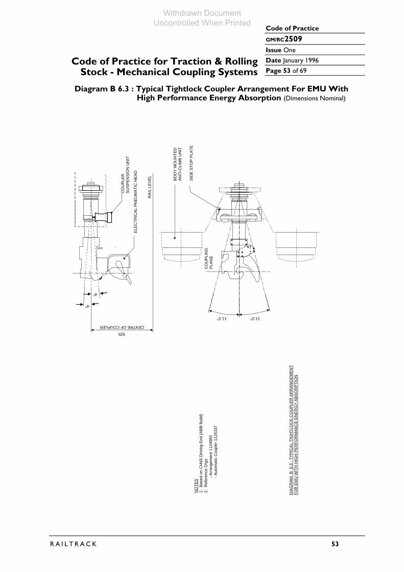
Code of Practice
GM/RC2509
Issue One
Date January 1996
Page 53 of 69
R A I L T R A C K 53
Code of Practice for Traction & RollingStock - Mechanical Coupling Systems
Diagram B 6.3 : Typical Tightlock Coupler Arrangement For EMU With High Performance Energy Absorption (Dimensions Nominal)
CENTRE OF COUPLER
925
4o
4o
RAI
L LE
VEL
ELEC
TRIC
AL P
NEU
MAT
IC H
EAD
CO
UPL
ERSU
SPEN
SIO
N U
NIT
CO
UPL
ING
PLAN
E
SID
E ST
OP
PLAT
E
BOD
Y M
OU
NTE
DAN
TI-C
LIM
B U
NIT
11.5o11.5o
NO
TES
1. B
ased
on
CI4
65 D
rivin
g En
d (A
BB B
uild
)2.
Ref
eren
ce D
rgs
- Ar
rang
emen
t 112
4983
- Au
tom
atic
Cou
pler
112
5337
DIA
GR
AM B
6.3
: TY
PIC
AL T
IGH
TLO
CK
CO
UPL
ER A
RR
ANG
EMEN
TFO
R E
MU
WIT
H H
IGH
PER
FOR
MAN
CE
ENER
GY
ABSO
RPT
ION
Withdrawn Document Uncontrolled When Printed

Code of Practice
GM/RC2509
Issue One
Date January 1996 Page 54 of 69
54 R A I L T R A C K
Code of Practice for Traction & Rolling Stock - Mechanical Coupling Systems
B7 Scharfenberg B 7.1 Usage Couplers Power cars and subset ends of CL373 (Eurostar) trainsets and CL332 EMU’s
(Heathrow Express, yet to be delivered). The following description applies only to CL373 vehicles.
Note: Compatibility between CL373 and CL332 is not a requirement.
B 7.2 System Components The system consists of the following elements:
• A Scharfenberg coupler head integral with a drawbar and a means of attaching the drawbar to the structure.
• A drawbar spring unit which provides resilience in transferring longitudinal tensile and compressive loads between vehicles during coupling and train operation.
• A means of centralising the coupler in the transverse plane to aid coupling. • A means of supporting the coupler in the vertical plane to aid coupling.
B 7.3 System Types The system is standard on CL373 except that the power car cab end coupler
does not carry electrical communications and does not feature hydraulically assisted uncoupling.
Diagram B7 shows the arrangement for the CL373 power car cab end coupler. B 7.4 System Description B 7.4.1 Scharfenberg Coupler The Scharfenberg coupler head is integral with the drawbar which is connected to
a drawbar pivot and which is itself flange mounted to the vehicle structure. The coupler head features automatic connection of the pneumatic supplies
between vehicles. All couplers except the cab end of the CL373 power car, also feature automatic connection of the electrical communications between vehicles.
When the couplers are connected there is no freedom between the coupler heads
and all relative vertical, transverse and roll movements between vehicles are accommodated at the pivot.
Coupling is achieved automatically by moving one vehicle towards the other at
slow speed. Coupling on curves and between vehicles at different heights is accommodated by an alignment bar followed by alignment cones.
Uncoupling on the power car cab ends is by manual operation of an uncoupling
lever. Uncoupling at all other locations is by manual operation of a hydraulic pump which operates an hydraulic actuator within the coupler body.
Withdrawn Document Uncontrolled When Printed

Code of Practice
GM/RC2509
Issue One
Date January 1996
Page 55 of 69
R A I L T R A C K 55
Code of Practice for Traction & RollingStock - Mechanical Coupling Systems
B 7.4.2 Drawbar Spring Units Drawbar spring units consist of a series of rubber elements integral with the
coupler at the drawbar pivot. B 7.4.3 Side Control Units Side control is integral with the coupler. B 7.4.4 Coupler Suspension Units Coupler vertical suspension is integral with the coupler. Coupler heights are
adjustable to allow maintenance of coupler height. B 7.4.5 System Standard The system described is only applicable to CL373 train sets.
Withdrawn Document Uncontrolled When Printed

Code of Practice
GM/RC2509
Issue One
Date January 1996 Page 56 of 69
56 R A I L T R A C K
Code of Practice for Traction & Rolling Stock - Mechanical Coupling Systems
Diagram B 7 : Typical Scharfenberg Coupler Arrangement (Dimensions Nominal)
RAI
L LE
VEL
VER
TIC
AL S
UPP
OR
T
1025
6O6O
10O10O
CO
UPL
ING
PLAN
E
NO
TES
1. B
ased
on
CI3
73 (E
uros
tar)
Pow
er C
ar C
ab E
nd
2. R
efer
ence
Drg
- Aut
omat
ic C
oupl
er T
MST
G F
1235
3
DIA
GR
AM B
7 :
TYPI
CAL
SC
HAR
FEN
BER
G C
OU
PLER
AR
RAN
GEM
ENT
Withdrawn Document Uncontrolled When Printed

Code of Practice
GM/RC2509
Issue One
Date January 1996
Page 57 of 69
R A I L T R A C K 57
Code of Practice for Traction & RollingStock - Mechanical Coupling Systems
B8 Semi Permanent B 8.1 Usage Couplers Intermediate ends of various fixed formation train sets where coupling/uncoupling
is only required on depots for maintenance purposes. B 8.2 System Components The system consists of the following elements:-
* A coupler head integral with the drawbar and a means of attaching the drawbar to the structure.
* A drawbar spring unit or an energy absorbing unit which provides resilience in transferring longitudinal tensile and compressive loads between vehicles during train operation.
* Side control units (where fitted) to centralise the coupler. * A coupler suspension unit (where fitted) to support the coupler during
coupling. B 8.3 System Types There are many different types in use dependent on the vehicle type,
manufacturer and date of build. As each type only interfaces with other vehicles fitted with identical couplers, detail descriptions of each type are not included.
Most installations, apart from the detail of the coupler head design, are similar to
the installations for the corresponding installation for the automatic unit end coupler.
Some types of coupler also carry the pneumatic and electrical communications
between vehicles. Diagram B8 shows the arrangement for a CL465 intermediate coupler. This type
features high performance energy absorption equipment to protect the vehicles during collisions.
Withdrawn Document Uncontrolled When Printed

Code of Practice
GM/RC2509
Issue One
Date January 1996 Page 58 of 69
58 R A I L T R A C K
Code of Practice for Traction & Rolling Stock - Mechanical Coupling Systems
Diagram B 8 : Typical Bar Coupler Arrangement For EMU With High Performance Energy Absorption (Dimensions Nominal)
SID
E ST
OP
PLAT
E
12O
12O
RAI
L LE
VEL
850CENTRE OF COUPLER
CO
UPL
ERSU
SPEN
SIO
NU
NIT
4.5O
4.5O
NO
TES
1. B
ased
On
CI4
65 In
term
edia
te E
nd (A
BB
Bui
ld)
2. R
efer
ence
Drg
s
- Arr
ange
men
t 112
4984
- Sem
i-Per
man
ent C
oupl
er 1
1253
36
DIA
GR
AM B
8 :
TYPI
CAL
BAR
CO
UPL
ER A
RR
ANG
EMEN
T FO
R
EMU
WIT
H H
IGH
PER
FOR
MAN
CE
ENER
GY
ABSO
RPT
ION
Withdrawn Document Uncontrolled When Printed
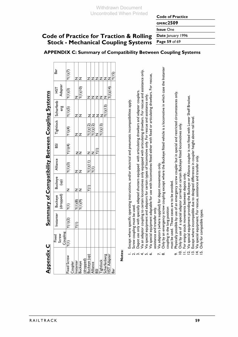
Code of Practice
GM/RC2509
Issue One
Date January 1996
Page 59 of 69
R A I L T R A C K 59
Code of Practice for Traction & RollingStock - Mechanical Coupling Systems
APPENDIX C: Summary of Compatibility Between Coupling Systems
Inst
ante
r
Buck
eye
(up)
BSI
Scha
rfen
berg
Bar
Tig
htlo
ck
Alli
ance
Buck
eye
(dro
pped
)
Fixe
d Sc
rew
Cou
pler
HST
Ada
pter
Fixe
dSc
rew
Cou
plin
gY
(1)
Inst
ante
r
Y(1
)
Y(1
)(2)
Buck
eye
(dro
pped
)
Y(1
)(8)
Y(1
)(9)
Y(1
)
Buck
eye
(up)
N Y(1
)
NN
Alli
ance
N Y(1
)(11
)Y
(1)
NY(1
)(3)
BSI
N N Y(1
)NNY
(1)(
4)
Tig
htlo
ck
N Y(1
)(12
)
N Y(1
)(13
)
Y(1
)(12
)
NY1)
(4)
Scha
rfen
ber
g
N N N Y(1
)(13
)NNNY
(1)(
5)
HST
Ada
pter
N N N NNNY(1
)(10
)
Y(1
)(3)
Y(1
)(14
)
Bar
N N N N Y(1
5)
NNNY(1
)(7)
N
No
tes:
1.Ex
cept
whe
re s
peci
fic o
pera
ting
inst
ruct
ions
, and
/or
elec
tric
al a
nd p
neum
atic
inco
mpa
tibili
ties
appl
y.2.
Scre
w c
oupl
ing
mus
t be
used
.3.
Dep
ot u
se o
nly
with
spe
cial
ly a
dapt
ed s
hunt
ers
equi
pped
with
art
icul
atin
g dr
awba
rs a
nd a
dapt
er c
oupl
ers.
4.V
ia a
n ad
apto
r co
uplin
g to
cer
tain
loco
mot
ives
onl
y eq
uipp
ed w
ith a
rtic
ulat
ing
draw
bars
. For
res
cue
and
assi
stan
ce o
nly.
5.V
ia s
peci
al e
quip
men
t and
ada
ptor
s fo
r ce
rtai
n ty
pes
of lo
com
otiv
e on
ly. F
or r
escu
e an
d as
sist
ance
onl
y.6.
Via
spe
cial
equ
ipm
ent a
dapt
able
for
use
with
loco
mot
ives
fitt
ed e
ither
with
fixe
d or
art
icul
atin
g dr
awba
rs. F
or r
escu
e,as
sist
ance
and
tran
sfer
onl
y.7.
Via
ada
ptor
s (w
here
sup
plie
d) fo
r de
pot m
ovem
ents
onl
y.8.
Onl
y by
an
emer
genc
y sc
rew
cou
plin
g ex
cept
whe
re th
e Bu
ckey
e fit
ted
vehi
cle
is a
loco
mot
ive
in w
hich
cas
e th
e In
stan
ter
coup
ling
in th
e lo
ng p
ositi
on
9.Ph
ysic
ally
pos
sibl
e by
use
of a
n em
erge
ncy
scre
w c
oupl
er b
ut in
spe
cial
and
res
tric
ted
circ
umst
ance
s on
ly.
10.
Onl
y by
use
of
a sp
ecia
l ada
ptor
car
ried
on
cert
ain
Buck
eye
fitte
d lo
com
otiv
es o
nly.
11.
For
empt
y st
ock
mov
emen
ts b
etw
een
depo
ts o
nly.
12.
Via
spe
cial
equ
ipm
ent p
rovi
ding
the
Buck
eye
or A
llian
ce c
oupl
er is
not
fitt
ed w
ith L
ower
She
lf Br
acke
t.13
.Ex
cept
whe
re in
com
patib
le d
ue to
des
igne
d di
ffere
nces
in c
oupl
er h
eigh
t abo
ve r
ail l
evel
.14
.V
ia s
peci
al e
quip
men
t. Fo
r re
scue
, ass
ista
nce
and
tran
sfer
onl
y.15
.O
nly
for
com
patib
le ty
pes.
App
endi
x C
Sum
mar
y o
f Co
mpa
tibi
lity
Bet
wee
n C
oup
ling
Sys
tem
s
mus
t be
used
. T
hese
cas
es a
re to
be
avoi
ded.
Withdrawn Document Uncontrolled When Printed

Code of Practice
GM/RC2509
Issue One
Date January 1996 Page 60 of 69
60 R A I L T R A C K
Code of Practice for Traction & Rolling Stock - Mechanical Coupling Systems
APPENDIX D: Adaptor Couplers and Equipment The following equipment is in current use for rescue and assistance of failed
trains: • HST Power cars to locomotives fitted with screw couplers only. BR Drawings L-A3-9504 L-A0-7488 • HST Power cars to HST power cars. BR Drawings L-A3-9504 L-A0-7488 • HST Power cars to locomotives fitted with either screw couplers or Buckeye
couplers. BR Drawing A1-A2-8401072 • HST Power cars to DMU fitted with BSI couplers. BR Drawing B1-A0-8201396. • DMUs fitted with BSI couplers to locomotives fitted with screw couplers. BR Drawing B1-A0-8201396 • EMU fitted with Tightlock couplers to loco hauled coaches (MK1, MK2
type). BR Drawing C-A0-19726 The use of this equipment is subject to operating restrictions contained within
working instructions and train crew manuals for each individual vehicle type. The above equipment does not necessarily comply with the requirements of
current Railway Group Standards.
Withdrawn Document Uncontrolled When Printed

Code of Practice
GM/RC2509
Issue One
Date January 1996
Page 61 of 69
R A I L T R A C K 61
Code of Practice for Traction & RollingStock - Mechanical Coupling Systems
APPENDIX E: Design of Coupling Systems to Avoid Derailment E 1.0 General The interaction between vehicles is influenced by the combination of the type and characteristics of the coupling equipment, the vehicle geometry, the characteristics of the vehicles suspension systems, the traction forces being applied between vehicles and the influences of the geometry of the track. Conditions which may lead to derailment are: a) Loss of surface contact between buffers, vestibule buffers and gangways during curving leading to interlocking of the equipment, which on movement out of the curve generates high lateral forces between vehicles which may result in the derailment quotient Y/Q reference [5] being exceeded. b) As a) above in combination with unloading of wheelsets if the interlocking causes the buffers or other equipment of one vehicle to remain supported or partially supported by the other. c) Insufficient buffer stroke and/or high values of the longitudinal stiffness of buffers and drawbar spring units which during curving results in high forces being generated at the buffer and which may result in the derailment quotient Y/Q being exceeded. d) Insufficient freedom of coupler movement to accommodate transverse and vertical displacements between vehicles during curving which may result in the derailment quotient Y/Q being exceeded. The conditions under which a), b), c) and d) above may occur are outlined below.
E 2 0 Interlocking E 2.1 Between Side Buffers
When two vehicles with side buffers operate through a reverse curve the overlap between the buffers is reduced by: a) The lateral separation of the vehicles due to the geometry of the reverse curve b) The action of the forces between vehicles acting on the flexible elements of the coupling and vehicle suspension system of each vehicle. c) The effect of any vertical differences (see Appendix F) in heights between buffers (due to reduction in overlap width caused by the buffer head curvature on circular or oval buffers).
Withdrawn Document Uncontrolled When Printed

Code of Practice
GM/RC2509
Issue One
Date January 1996 Page 62 of 69
62 R A I L T R A C K
Code of Practice for Traction & Rolling Stock - Mechanical Coupling Systems
The highest risk of interlocking occurs during propelling movements on reverse curves where the traction forces acting between the buffer heads generate a net lateral component (due to the buffer head curvature) at the vehicle ends which causes the vehicle bodies to rotate on the suspensions thus increasing the lateral separation between vehicles. Vehicle types which (by virtue of their geometry) generate large overthrows at the vehicle ends on curves and with soft lateral suspensions are most likely to be at risk of interlocking. Risks can be eliminated or minimised at the design stage by consideration of vehicle geometry, buffer head shape, profile and characteristic, and drawgear geometry and characteristics. Where risks cannot be entirely eliminated, analysis is based on demonstrating that the risks are no worse and preferably significantly better in comparison with existing vehicle combinations which operate in similar circumstances under the same or similar traction conditions. In particular vehicles which operate on a regular basis in push pull operations require detailed analysis. Analysis is generally carried out using 2 or 3 dimensional mathematical modelling of the vehicles suspension and coupling system on specified minimum radii reverse curves. The parameters typically included in the model are shown in Diagram E.1. E 2.2 Between Vestibule Buffer and Gangways When two vehicles coupled with Buckeye couplers operate through a reverse curve where one vehicle is fitted with a vestibule buffer and the other is fitted with a gangway, or when both vehicles are fitted with vestibule buffers, there is a risk that the equipment may interlock. The circumstances only occur when the lateral displacement between vehicles is accompanied by a vertical difference in the height between vestibule buffers or gangway (see Diagram E2). The circumstances which contribute to height differences are listed in Appendix F. If locking occurs, movement out the curve will cause considerable damage to the equipment and generate high wheel flange to rail forces in combination with partial wheelset unloading which may result in the derailment quotient Y/Q reference [5] being exceeded. Risks can be eliminated at the design stage by ensuring that the top surface of the vestibule buffer is fitted with projections which ensure surface contact between vestibule buffers is maintained under all operating conditions.
Withdrawn Document Uncontrolled When Printed

Code of Practice
GM/RC2509
Issue One
Date January 1996
Page 63 of 69
R A I L T R A C K 63
Code of Practice for Traction & RollingStock - Mechanical Coupling Systems
E 2.3 Between Vestibule Buffers, Gangway and Side Buffers When two vehicles are coupled with Buckeye couplers the side buffers are retracted and on straight track there is a gap between the buffers and the vestibule buffers or gangways are in contact with each other. During curving the side buffer of one vehicle may overlap with the vestibule buffer or gangway. Providing the sliding contact occurs without the risk of the edge of the side buffer contacting the edge of the vestibule buffer or gangway then no damage or risk of derailment will result. The risks of edge contact occurring are increased during propelling and if the geometry and characteristics of the side buffers and vestibule buffers are incompatible, or if one vehicle is not fitted with a vestibule buffer or gangway. Risks can be eliminated at the design stage by analysis of the vestibule buffer/gangway and side buffer interaction during curving and selection of compatible equipment.
E 3.0 Interaction of Coupling Equipment during Curving
During operation over all types of curves the displacements generated between vehicles are accommodated (and to an extent controlled) by movement or displacement of the side buffers, vestibule buffers, and drawbars. Operation through horizontal reverse curves will generally generate the maximum drawbar angles in the horizontal plane. Operation through horizontal simple curves will generate the maximum compression on side and vestibule buffers and extension in the drawbar. Operation through vertical and convex curves combined, with vertical height variations (see Appendix F) between vehicles will generate the maximum drawbar angles in the vertical plane. Insufficient freedom to accommodate displacement or the generation of high forces in the flexible elements may result in damage to the coupling equipment or the forces generated at the vehicle ends may result in the derailment quotient Y/Q being exceeded. Risks can be eliminated at the design stage by analysis of the interaction between vehicles during operation through minimum curves of the coupling equipment/vehicle body interface and the selection of suitable coupling equipment.
Withdrawn Document Uncontrolled When Printed

Code of Practice
GM/RC2509
Issue One
Date January 1996 Page 64 of 69
64 R A I L T R A C K
Code of Practice for Traction & Rolling Stock - Mechanical Coupling Systems
Diagram E 1: Typical Parameters In A 2-D Model Of Screw Coupled Vehicles On A Reverse Curve
P
R1
R2
R3
R4
P
NO
TES
1. P
aram
eter
s
-
Tra
ck g
eom
etry
- V
ehic
le, b
ogie
geo
met
ry
-
Buf
fer g
eom
etry
, cur
vatu
re a
nd c
hara
cter
istic
- D
raw
bar g
eom
etry
,cha
ract
eris
tic, r
otat
ion
stop
and
scr
ew c
oupl
er
-
Sid
e co
ntro
l geo
met
ry, c
hara
cter
istic
(whe
re fi
tted)
- L
ater
al s
uspe
nsio
n ch
arac
teris
tic
-
Whe
el to
trac
k cl
eara
nce
P =
Pr
opel
ling
Forc
eR
,
R
,R
,
R
=
Rea
ctio
ns a
t tra
ck d
ue to
late
ral f
orce
cre
ated
at b
uffe
rs1
23
4
DIA
GR
AM E
1 :
TYPI
CAL
PAR
AMET
ERS
IN A
2D
MO
DEL
OF
SCR
EW C
OU
PLED
VEH
ICLE
S O
N A
REV
ERSE
CU
RVE
Withdrawn Document Uncontrolled When Printed

Code of Practice
GM/RC2509
Issue One
Date January 1996
Page 65 of 69
R A I L T R A C K 65
Code of Practice for Traction & RollingStock - Mechanical Coupling Systems
Diagram E 2 : Circumstances Leading To Vestibule Buffer Locking
BU
CK
EY
E C
OU
PLE
RS
VERTICAL DISPLACEMENTDUE TO HEIGHT DIFFERENCESBETWEEN VEHICLES
LATE
RA
L D
ISP
LAC
EM
EN
T D
UE
TO R
EV
ER
SE
CU
RV
E
VE
STI
BU
LE B
UFF
ER
OR
GA
NG
WA
Y V
EH
. 1
VE
STI
BU
LE B
UFF
ER
VE
H. 2
DIA
GR
AM
E 2
: C
IRC
UM
STA
NC
ES
LE
AD
ING
TO
VE
STI
BU
LE B
UFF
ER
LO
CK
ING
Withdrawn Document Uncontrolled When Printed

Code of Practice
GM/RC2509
Issue One
Date January 1996 Page 66 of 69
66 R A I L T R A C K
Code of Practice for Traction & Rolling Stock - Mechanical Coupling Systems
APPENDIX F: Sources of Height Variations between Vehicles or Coupling Equipment
F 1.0 Vehicle Specific • Differences in design height of buffers and couplers. • Height setting tolerance (typically ± 12mm but varies according to vehicle
maintenance instructions). • Suspension movements between tare and laden body loads • Reduction in wheel diameters due to wheel wear and tyre turning (up to
40mm radial) but varies according to vehicle type. On certain vehicle types reduction in wheel diameter is compensated by packing or suspension adjustment.
• Pitch effect on vehicle bodies due to difference in wheel diameters on individual wheelsets. (On certain vehicle types differences in wheel diameter between individual wheelsets is controlled).
• Deflated suspensions. • Pitch effect due to the suspension being deflated on one bogie only. • Suspension creepage. • Differences in dynamic behaviour F 2.0 Track Specific * Effect of vertical concave and convex curves. * Change of track cant * Track defects * Traverser ramps and ramps onto concrete aprons in depots (some
ramps maybe up to 100mm in height).
Withdrawn Document Uncontrolled When Printed

Code of Practice
GM/RC2509
Issue One
Date January 1996
Page 67 of 69
R A I L T R A C K 67
Code of Practice for Traction & RollingStock - Mechanical Coupling Systems
APPENDIX G : Minimum Track Geometry Data Typically Used For Vehicle Design Purposes. Note: Allowances must also be made for track maintenance limits
Nominal track gauge 1432 mm Gauge widening, curve radii 200 - 141 m 7 mm Gauge widening, curve radii 140 - 111 m 13 mm Gauge widening, curve radii 110 - 70 m 19 mm Minimum horizontal track radius: - Mainline 120 m - Non-passenger lines and sidings 90 m (1) Minimum horizontal track reverse radius with a 3 m intermediate straight: - Mainline 140m - Non-passenger lines and sidings 120m Minimum vertical track radius, concave or convex: - Mainline 500m - Non-passenger lines and sidings 200m Maximum installed cant 150 mm Some with 200mm cant now installed Maximum cant gradient 1 in 400 Maximum rate of change of cant 85 mm/sec Maximum cant deficiency 6° Maximum rate of change of cant deficiency 70 mm/sec NOTES (1) Certain freight vehicles may be required to operate on curves of
70m radius. (2) See also references [7] and [8]. (3) For specific requirements for individual vehicles see vehicle
specification.
Withdrawn Document Uncontrolled When Printed

Code of Practice
GM/RC2509
Issue One
Date January 1996 Page 68 of 69
68 R A I L T R A C K
Code of Practice for Traction & Rolling Stock - Mechanical Coupling Systems
References Railway Group Standards [1] GM/RT2100 Structural requirements for railway vehicles. [2] GM/RT2102 Structural requirements for drawgear and
buffers on railway vehicles. [3] GM/RT2149 Kinematic gauging requirements for railway
vehicles. [4] GM/RT2160 Ride vibration and noise environment for
railway vehicles. [5] GM/TT0087 Resistance of railway vehicle to derailment
and rollover. [6] GM/TT0401 Rail vehicle mechanical coupling systems. [7] GC/RT5001 Standard for the design of permanent way. [8] GC/EM0049 Track design handbook. [9] GO/RT3255 Safety requirements for shunting staff. [10] BR 87109 Railtrack Rule Book. [11] GM/TT0403 Technical requirements for the haulage of
dead traction units. UIC Leaflets [12] 520 Wagon coaches and vans - drawgear. [13] 521 Coaches, vans, wagons, tractive stock. Clearance to be provided at vehicle
extremities. [14] 526-1 Wagons - buffers with a stroke of 105mm. [15] 526-2 Wagons - buffers with a stroke of 75mm. [16] 527-1 Coaches, vans and wagons - dimensions of
buffer heads, track layout on s-curves. [17] 527-2 Coaches, vans and wagons - dimensions of
buffer heads, rolling stock built before 01-01-65. [18] 528 Buffer gear for coaches. [19] 645 Regulations applicable to powered units used
on International service when running over curves.
[20] 825 Technical specification for the supply of drawhooks.
[21] 826 Technical specification for the supply of screw couplings.
[22] 827-1 Technical specification for the supply of elastomer components for buffers.
[23] 827-2 Technical specification for the supply of steel rings for buffers.
[24] 828 Technical specification for the supply of welded components for buffers.
Withdrawn Document Uncontrolled When Printed

Code of Practice
GM/RC2509
Issue One
Date January 1996
Page 69 of 69
R A I L T R A C K 69
Code of Practice for Traction & RollingStock - Mechanical Coupling Systems
Other Standards And Related Documents [25] Health and Safety at Work etc. Act. 1974 [26] Ergonomics standards and guidelines for designers, by
Stephen Phesant ISBN 0 580 15391 6 (See also BS PP 7317 Ergonomics - standards and
guidelines for designers) [27] BR MT/235 Requirements and Recommendations for the
Design of Wagons running on BR lines [28] GM/RM2500 Rail Vehicle Acceptance & Registration Manual [29] GM/RT2450 Qualification of Suppliers of Safety Critical Engineering
Products and Services.
Withdrawn Document Uncontrolled When Printed