Code of Practice for Torch-on Membrane Systems for … · Code of Practice for Torch-on Membrane...
74
Code of Practice for Torch-on Membrane Systems for Roofs and Decks (for the selection, design and installation of reinforced modified bituminous materials) 2 nd Edition Published September 2015 Prepared by the Waterproofing Membrane Association (NZ) Incorporated (previously the Membrane Group of New Zealand) www.membrane.org.nz ISBN 978-0-473-309862 (for Download)
-
Upload
truongdung -
Category
Documents
-
view
221 -
download
0
Transcript of Code of Practice for Torch-on Membrane Systems for … · Code of Practice for Torch-on Membrane...

Code of Practice
for
Torch-on Membrane Systems
for
Roofs and Decks
(for the selection, design and installation of reinforced modified bituminous materials)
2nd Edition Published September 2015
Prepared by the Waterproofing Membrane Association (NZ) Incorporated (previously the Membrane Group of New Zealand)
www.membrane.org.nz
ISBN 978-0-473-309862 (for Download)

Code of Practice for Torch-on Membrane Systems Page 2 of 74 Waterproofing Membrane Association NZ Inc., www.membrane.org.nz Consultation Version July 2016
. . . setting best practice in waterproof membranes . . .
Waterproofing Membrane Association NZ Incorporated
The Waterproofing Membrane Association NZ Incorporated (referred to as "WMAI") is a group of companies in New Zealand who aim to set the benchmark for best industry practice for waterproof membranes. All members undertake to comply with the Rules and Codes of Practice of our Association.
Membership is open to any interested party. For further information, please contact [email protected] or go to www.membrane.org.nz.
WMAI Ordinary Members:
Ardex NZ Ltd
Bostik New Zealand Ltd
Equus Industries Ltd
Hitchins NZ Ltd
Jaydex International Ltd
Nuplex Industries Ltd
Nuralite Waterproofing Ltd
Sika NZ Ltd
Viking Group Ltd
Copyright The copyright of this document is the property of the publisher, being the Waterproofing Membrane Association Inc.
Reproduction of excerpts is permitted, but must include the citation: "Reproduced from the Code of Practice for Torch-on Membrane Systems, Waterproofing Membrane Association (NZ) Inc."
Disclaimer This document is intended as guidance only, and is not specific to any particular project or waterproofing system. The WMAI, in consultation with the New Zealand construction industry, has established this Code of Practice as the guide to best
practice in the design and installation of torch-on membrane systems. While the Association has taken care in preparing this document, users must themselves ensure all aspects of any particular
project are allowed for when establishing compliance with all the relevant requirements of the Building Act 2004 or the Building Code in all cases.
Document History This document may be updated from time to time. Refer to http://www.membrane.org.nz for the most recent update(s) of this Code of Practice (if any):
Version Date Reason(s) for Amendment
2nd
Edition July 2016 Consultation Version July 2016
2nd Edition September 2015 Published in consultation with MBIE.
1st Edition October 2008 Published.
Public Comment draft July 2008 Draft distributed for public comment. Feedback received and draft revised.
Comments on this Code of Practice are welcome. Please send all comments to: [email protected].
Other Published Codes of Practice by the WMAI: Code of Practice for Internal Wet Area Membranes

Code of Practice for Torch-on Membrane Systems Page 3 of 74 Waterproofing Membrane Association NZ Inc., www.membrane.org.nz Consultation Version July 2016
. . . setting best practice in waterproof membranes . . .
Contents 1. Purpose, Scope and Limitations ...................................................................................... 5
1.1 Purpose .................................................................................................................................... 5 1.2 Scope ....................................................................................................................................... 5 1.3 Limitations................................................................................................................................. 5 1.4 Using this Code of Practice ........................................................................................................ 6
2. Torch-on Membrane Properties ....................................................................................... 7 2.0 General ..................................................................................................................................... 7 2.1 The Development and Main Classifications of Torch-on Membranes ........................................... 7 2.2 Test Methods and Performance Criteria ..................................................................................... 8 2.3 Properties of Materials ............................................................................................................. 10 2.4 Durability and Maintenance...................................................................................................... 12 2.5 Product Performance ............................................................................................................... 12 2.6 Types of Torch-on Membranes ................................................................................................ 12
3. Membrane Selection ....................................................................................................... 17 3.0 General ................................................................................................................................... 17 3.1 Material Selection .................................................................................................................... 17 3.2 Multiple-layered Systems ......................................................................................................... 22 3.3 Coating and Protection ............................................................................................................ 22 3.4 Over-Surfacing ........................................................................................................................ 22 3.5 Concrete Over or Raised/Removable Surfaces......................................................................... 23 3.6 Exposed Membranes ............................................................................................................... 23 3.7 Accessories ............................................................................................................................ 24 3.8 Insulated Roof Membrane Assembly ........................................................................................ 24 3.9 Roof Gardens/Green Roofs ..................................................................................................... 25 3.10 Vehicle Decks ......................................................................................................................... 25
4. Design ........................................................................................................................ 26 4.0 General ................................................................................................................................... 26 4.1 Substrate Requirements .......................................................................................................... 27 4.2 Insulated Roofing Membrane Assembly ................................................................................... 29 4.3 Existing Roof Torch-on Membranes ......................................................................................... 30 4.4 Design Detailing ...................................................................................................................... 31 4.5 Typical Installation Steps and Appropriate Design Detailing ...................................................... 32
5. Site Practice .................................................................................................................... 43 5.0 General ................................................................................................................................... 43 5.1 Administration/Supervision ...................................................................................................... 43 5.2 Project Commencement .......................................................................................................... 43 5.3 Acceptable Information ............................................................................................................ 44 5.4 Handling of Materials ............................................................................................................... 44 5.5 Working Conditions ................................................................................................................. 44 5.6 Scheduling of Work ................................................................................................................. 44 5.7 Care of Adjacent Surfaces ....................................................................................................... 45 5.8 Care of Completed Work ......................................................................................................... 45 5.9 Fire Safety and Prevention ...................................................................................................... 45 5.10 Workmanship .......................................................................................................................... 46 5.11 Training................................................................................................................................... 46 5.12 Health and Safety .................................................................................................................... 46 5.13 Successful Site Practice .......................................................................................................... 47
6. Installation ...................................................................................................................... 48 6.0 General ................................................................................................................................... 48 6.1 Pre-Inspection ......................................................................................................................... 48 6.2 Substrate Inspection ................................................................................................................ 49 6.3 Installation Procedure .............................................................................................................. 50 6.4 Post-Installation Work .............................................................................................................. 54 6.5 Flood Testing .......................................................................................................................... 55 6.6 Post-Installation Penetrations .................................................................................................. 55
7. Maintenance (or "through-life care") ............................................................................. 56 7.0 General ................................................................................................................................... 56 7.1 Defects Liability ....................................................................................................................... 56 7.2 Preventive Maintenance .......................................................................................................... 57 7.3 Remedial Work........................................................................................................................ 57

Code of Practice for Torch-on Membrane Systems Page 4 of 74 Waterproofing Membrane Association NZ Inc., www.membrane.org.nz Consultation Version July 2016
. . . setting best practice in waterproof membranes . . .
7.4 Maintenance Servicing ............................................................................................................ 58 7.5 Repair Procedures .................................................................................................................. 59 7.6 Re-coating .............................................................................................................................. 59 7.7 Re-surfacing ........................................................................................................................... 59
8. Definitions ....................................................................................................................... 61 Appendix 1: Related Documents, Standards, Legislation and Websites ......................... 71 Appendix 2: About the WMAI ............................................................................................. 73 Appendix 3: About WMAI Codes of Practice ..................................................................... 73
List of Figures
Figure 1 – System Selection Flow Chart .............................................................................................................21 Figure 2 – Typical roof/deck gutter outlet with rebated gutter flange .....................................................................32 Figure 3 – Box sump with in-built overflow ..........................................................................................................32 Figure 4 – Central gutter outlet with proprietary dome outlet ................................................................................32 Figure 5 – Perimeter gutter outlet with proprietary dome outlet ............................................................................32 Figure 6 – Internal gutter to parapet, with under-flashings ....................................................................................33 Figure 7 – Proprietary scupper and rainwater head through parapet wall .............................................................33 Figure 8 – Internal and external corners with under-flashing, either in plan or section ...........................................33 Figure 9 – Under-flashing of external corner with gusset......................................................................................34 Figure 10 – Under-flashing of internal corner.......................................................................................................34 Figure 11 – Metal drip edge, rebated and under-flashed ......................................................................................34 Figure 12 – Verge with under-flashing around shaped timber packer ...................................................................34 Figure 13 – Verge with metal over-flashing and membrane under-flashing ...........................................................35 Figure 14 – Verge with metal over-flashing, membrane under-flashing & expressed timber trim ............................35 Figure 15 – Welted barge ...................................................................................................................................35 Figure 16 – Welted barge with folded under-flashing ...........................................................................................35 Figure 17 – Mechanical fixing with termination bar ..............................................................................................36 Figure 18 – Termination into concrete or masonry wall with metal over-flashing ...................................................36 Figure 19 – Typical parapet capping ...................................................................................................................36 Figure 20 – Bond-breaker over plywood sheet ....................................................................................................37 Figure 21 – Level-entry door sill ..........................................................................................................................37 Figure 22 – Direct-fixed door sill, with metal flashing ...........................................................................................37 Figure 23 – Wall/floor/deck junction, with under-flashing ......................................................................................38 Figure 24 – Wall/deck junction with under-flashing (and full backing support if a timber wall) ................................38 Figure 25 – Termination under and behind existing wall cladding .........................................................................38 Figure 26 – Vent for ventilating the membrane ....................................................................................................38 Figure 27 – Roof-cavity vent on timber plinth.......................................................................................................38 Figure 28 – Orientation of plinth to allow for water flow ........................................................................................39 Figure 29 – Plinth footing detail ..........................................................................................................................39 Figure 30 – Typical vertical pipe penetration with proprietary over- and under-sleeve ...........................................39 Figure 31 – Typical vertical pipe penetration .......................................................................................................40 Figure 32 – Typical horizontal pipe penetration ...................................................................................................40 Figure 33 – Roof ridge with over-flashing ............................................................................................................40 Figure 34 – Roof ridge with under-flashing ..........................................................................................................40 Figure 35 – Membrane up wall and under roofing, with solid support....................................................................40 Figure 36 – Metal expansion joint cap, double-sloped, fixed both sides ................................................................41 Figure 37 – Metal expansion joint cap, centre-peaked, fixed both sides................................................................41 Figure 38 – Metal expansion joint cap, single-sloped, fixed one side ....................................................................41 Figure 39 – Flush expansion joint .......................................................................................................................41 Figure 40 – Proprietary expansion cap with under-flashing ..................................................................................41
List of Tables
Table 1 – Sheet Properties .................................................................................................................................. 9 Table 2 – Performance Requirements .................................................................................................................. 9 Table 3 – Aging Properties: Exposure to Temperature.........................................................................................10 Table 4 – Aging Properties: Exposure to Water ...................................................................................................10 Table 5 – Typical Torch-on Membrane Systems ..................................................................................................16 Table 6 – Torch-on Membrane Layers Available in New Zealand .........................................................................20 Table 7 – Plywood Design Chart: Minimum Plywood Thickness ...........................................................................28

Code of Practice for Torch-on Membrane Systems Page 5 of 74 Waterproofing Membrane Association NZ Inc., www.membrane.org.nz Consultation Version July 2016
. . . setting best practice in waterproof membranes . . .
1. Purpose, Scope and Limitations
1.1 Purpose This Code of Practice provides the Waterproofing Membrane Association's recommended best practices for waterproofing solutions using torch-on membrane systems. This Code of Practice aims to foster confidence for all parties involved in the use of torch-on membrane systems throughout the selection, design, consenting and installation process. It is published with the intention of establishing and improving industry practice, performance standards, systems, materials and their application, and to ensure that public and industry confidence in the membrane industry is preserved. Further, this Code of Practice may be used to develop recommended training criteria and set installation methodology benchmarks for the industry.
1.2 Scope This Code of Practice is applicable to the design and application of torch-on membrane systems for residential, commercial or industrial buildings that meet Importance Levels 2, 3 or 4 of AS/NZS1170, for structures designed in concrete, steel or timber and which comply with the New Zealand Building Code. The general principles of installation design are the same for all Importance Levels, but detail design will depend on wind-loading, with particular reference to the method of fixing the membrane to the substrate. This Code also addresses the appropriate design and installation of the substrates necessary to support the membrane system. Installation of torch-on membrane systems is part of the Licensed Building Practitioner (LBP) scheme and is Restricted Building Work (RBW).
1.3 Limitations This Code of Practice does not cover the design or construction of the building structure, which must comply with the New Zealand Building Code. The building structure shall properly support and accommodate the roof, wall and deck substrate as required for the external waterproofing, and any over-surfacing systems or removable surfaces, as described in Sections 3.4 and 3.5. This Code of Practice does not apply to the waterproofing of internal gardens, water features, swimming pools or industrial wet processing areas. This Code of Practice is limited to the design and application of membrane systems in all situations up to and including High wind zones where wind speeds do not exceed 44m/s. For wind zones greater than High, in accordance with NZS1170.2:2011, the building-specific wind uplift design for the membrane installation including fixing type and layout must be provided by the Supplier and the design confirmed by the Designer. Sections 3.8, 3.9, 3.10 and 4.2 concerning insulated roofs, inverted roofs, roof gardens and vehicle decks are introductory only, and will be covered in detail in later publications. ___________________________________________________________________________________________
Acronyms: LBP = Licenced Building Practitioner; RBW = Restricted Building Work, WMAI = Waterproof Membrane Association NZ Incorporated

Code of Practice for Torch-on Membrane Systems Page 6 of 74 Waterproofing Membrane Association NZ Inc., www.membrane.org.nz Consultation Version July 2016
. . . setting best practice in waterproof membranes . . .
This Code of Practice does not apply to contractual disputes, which should be dealt with under the provisions of the contract between the parties involved. This Code of Practice is not specific to any particular project and is not intended to be or to provide a project specification; however, the information will provide assistance for preparing a design and a specification for the membrane work.
1.4 Using this Code of Practice 1.4.1 The following descriptions of the key parties responsible for the waterproofing membrane system have been used:
"Designer" means the person or company who specifies the waterproofing system; they may be an Architect, an Engineer or the Supplier.
"Supplier" means the New Zealand company that supplies the waterproofing system.
"Applicator" means the contracted company responsible for the installation of the waterproofing system.
1.4.2 Text styles indicate the following:
Statements in boxes are highlighted for special emphasis and must be adhered to.
Shaded text indicates information that is introductory commentary only and which will be developed fully in future publications. Such information is not a mandatory part of this Code of Practice.
1.4.3 In reading this Code of Practice, note that:
Bullet-point lists are not in order of importance, and not all items may be relevant to a specific project.
Numbered lists are generally in a process order, though some items may not apply to a specific project.
1.4.4 All acronyms used in any chapter are defined at the foot of the first page of each chapter. 1.4.5 Information may be repeated in several chapters so that each chapter is complete without necessarily requiring cross-referencing to other chapters. 1.4.6 Some pages are intentionally left fully or partially blank to allow related pages to be viewed together or to allow a specific list to be viewed in its entirety.

Code of Practice for Torch-on Membrane Systems Page 7 of 74 Waterproofing Membrane Association NZ Inc., www.membrane.org.nz Consultation Version July 2016
. . . setting best practice in waterproof membranes . . .
2. Torch-on Membrane Properties This chapter is written primarily for use by the Building Consent Authority, but may also be of use to the Designer. It sets out the minimum properties of any component of a torch-on membrane system.
2.0 General A fundamental requirement of any torch-on membrane system is that it must provide protection from all weather conditions likely to be experienced during its design life. All individual layers in a torch-on membrane system must be watertight, and together the whole system must be waterproof. Three items have been developed in this Code of Practice to help select the most appropriate torch-on membrane system:
2.6 Types of Torch-on Membranes lists membranes developed for standard and specialised service conditions.
Table 6 –Torch-on Membrane Layers Available in New Zealand lists the most common combinations of membranes that can form a waterproof membrane system.
Figure 1 – System Selection Flow Chart shows the range of options based on the surface to which it is being applied and the required service life of the membrane.
2.1 The Development and Main Classifications of Torch-on Membranes Torch-on membranes have their beginning in fibre-reinforced bitumen membrane products that were used as waterproof roof membranes for over 100 years. The early membranes comprised "blown" (oxidised) bitumens reinforced with organic felts or hessian, and laid in "steep" or hot-poured bitumen in a multi-layer system. With the advance of polymer technology in the middle of last century, particularly after World War II, attention turned to the modification of roofing bitumens with synthetic polymers to improve flexibility, toughness, cold temperature and ageing performance. Continual development created a wide range of high-performance polymer-modified bitumen roll products for specific building, temperature, environmental and design conditions. There are two primary classes of polymer-modified bitumen (torch-on) membranes:
APP (atactic polypropylene) modified bitumens o Harder and less flexible. o Provide very good heat and UV resistance and durability properties. o Known as plastomeric products.
SBS (styrene-butadiene-styrene) modified bitumens o Softer and more flexible. o Provide enhanced elasticity and flexibility, particularly at low service temperatures
such as in the colder climate zones as defined in AS1 of clause H1 of the NZ Building Code.
o Known as elastomeric products. Some torch-on membranes combine the two, either as a mix of polymer types within one single bitumen mass, or as a combined product with a base layer of SBS elastomer and a top layer of APP (or derivative) plastomer to give maximum durability with maximum flexibility. __________________________________________________________________________________________
Acronyms: APP = atactic polypropylene; ASTM = American Society for Testing and Materials; DIN = Deutsch Industrie Norm; EN = European Norm; MDV = Manufacturers declared value; SBS = styrene-butadiene-styrene; UEAtC = European Union for technical approval in construction; UV = ultra violet

Code of Practice for Torch-on Membrane Systems Page 8 of 74 Waterproofing Membrane Association NZ Inc., www.membrane.org.nz Consultation Version July 2016
. . . setting best practice in waterproof membranes . . .
All torch-on membranes are reinforced with a continuous reinforcement medium during the manufacturing process to give stability and strength to the membrane. The reinforcement materials have advanced from those originally used with multi-layer hot-mop membranes of previous generations. Depending on the quality and role of the finished membrane, there is a choice of reinforcement available, including:
Glass fibre mat, which provides dimensional stability with little movement flexibility under stress.
Non-woven polyester fabric of various weights, which provides strength but allows some movement flexibility under stress.
Non-woven polyester fabric with glass fibre strands or a mat, which provides both dimensional stability and strength, and flexibility.
Multi-layers of glass fibre mat and non-woven polyester fabric, which provide an extremely stable membrane for use under adverse conditions.
All torch-on membranes are produced with a functional and protective surface, which will relate to the intended end-use. These include:
Light polythene film, sand or talc surfacing, generally for base sheet application.
Coloured aggregate or slate flake for decorative weathering and UV resistance, generally for cap sheet application.
Bonded metal film and other UV-protective or reflective finishes, generally as a specialised decorative finish.
2.2 Test Methods and Performance Criteria Selected test methods and performance criteria of membrane components are set out in Tables 1-4. All tests relate to the properties of the torch-on membrane itself. If a torch-on membrane meets the requirements, then it will also comply with the as-laid tests stipulated in the UEAtc Technical Guide, and which are generally also included in Manufacturers' and Suppliers' literature. This Code of Practice is based on existing New Zealand practice supplemented with European practice and performance criteria, where most of the major torch-on membrane Manufacturers (or their holding organisations) are based. The European Standards organisation (UEAtC) gives both a coherent framework for the evaluation of the performance of torch-on modified bituminous membranes and a definitive and wide-ranging set of standards (called European Norms) for the testing of such membranes. Other organisations such as ASTM, CGBS and DIN have similar testing criteria, which can be used to show performance capability. While the purpose of this section is to ensure that material of an assured quality is supplied to site, it should be noted that these performance criteria are quite distinct from on-site performance, which can be influenced by on-site installation practice and local environmental conditions.
Code of Practice for Torch-on Membrane Systems Page 9 of 74 Waterproofing Membrane Association NZ Inc., www.membrane.org.nz Consultation Version July 2016
. . . setting best practice in waterproof membranes . . .
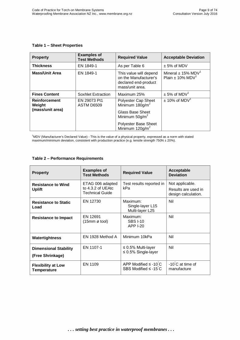
Table 1 – Sheet Properties
Property Examples of Test Methods
Required Value Acceptable Deviation
Thickness EN 1849-1 As per Table 6 ± 5% of MDV
Mass/Unit Area EN 1849-1 This value will depend on the Manufacturer's declared end-product mass/unit area.
Mineral ± 15% MDV1
Plain ± 10% MDV1
Fines Content Soxhlet Extraction Maximum 25% ± 5% of MDV1
Reinforcement Weight (mass/unit area)
EN 29073 Pt1 ASTM D6509
Polyester Cap Sheet Minimum 180g/m
2
Glass Base Sheet Minimum 50g/m
2
Polyester Base Sheet Minimum 120g/m
2
± 10% of MDV1
1MDV (Manufacturer's Declared Value) - This is the value of a physical property, expressed as a norm with stated
maximum/minimum deviation, consistent with production practice (e.g. tensile strength 750N ± 20%).
Table 2 – Performance Requirements
Property Examples of Test Methods
Required Value Acceptable Deviation
Resistance to Wind Uplift
ETAG 006 adapted to 4.3.2 of UEAtc Technical Guide
Test results reported in kPa
Not applicable.
Results are used in design calculation.
Resistance to Static Load
EN 12730 Maximum: Single-layer L15 Multi-layer L25
Nil
Resistance to Impact EN 12691 (15mm ø tool)
Maximum: SBS I-10 APP I-20
Nil
Watertightness EN 1928 Method A
Minimum 10kPa Nil
Dimensional Stability
(Free Shrinkage)
EN 1107-1 ≤ 0.5% Multi-layer ≤ 0.5% Single-layer
Nil
Flexibility at Low Temperature
EN 1109 APP Modified ≤ -10°C
SBS Modified ≤ -15°C
-10°C at time of
manufacture

Code of Practice for Torch-on Membrane Systems Page 10 of 74 Waterproofing Membrane Association NZ Inc., www.membrane.org.nz Consultation Version July 2016
. . . setting best practice in waterproof membranes . . .
Table 3 – Aging Properties: Exposure to Temperature
Exposure to Temperature (24 weeks at 70°C)
Property Examples of Test Methods
Required Value
Flexibility EN 1296 and EN 1109
Non Cracking ≤ 0°C
Maximum deviation of ±15°C
from initial low temperature flexibility
Flow Resistance at Elevated Temperature
EN 1296 and EN 1110
APP Modified ≥ 125°C
SBS Modified ≥ 100
°C
Table 4 – Aging Properties: Exposure to Water
Exposure to Water (1-week immersion at 230°C)
Property Examples of Test Methods
Required Value
Flexibility at Low Temperature
EN 1296 and EN 1109
Maximum deviation of ±5°C from initial low
temperature flexibility
2.3 Properties of Materials The performance requirements for materials are generally set out in 2.3.1 to 2.3.12. A balance of values for the listed attributes is desirable, though they must remain within the levels of acceptable performance for any given attribute. Some of these requirements are a general expression rather than a specific measurement of specific requirements as detailed in Tables 1-4. 2.3.1 Tensile Strength The torch-on membrane must have sufficient tensile strength to resist stresses caused by internal and external forces imposed upon it. Torch-on membranes should never be expected to perform as structural members. 2.3.2 Elongation at Break The torch-on membrane must have sufficient elasticity to prevent rupture due to elongation. 2.3.3 Tear Resistance The torch-on membrane must resist tearing or ripping when subjected to anticipated external and internal forces. This is particularly relevant when used in exposed conditions. 2.3.4 Bond Strength to Substrate Where the torch-on membrane is of a bonded or partially-bonded type and used in exposed weather conditions it must have sufficient adhesion to resist wind uplift forces without failure. Forces can result from wind loads, thermal movement, settlement and movement from discontinuity of substrate.
Code of Practice for Torch-on Membrane Systems Page 11 of 74 Waterproofing Membrane Association NZ Inc., www.membrane.org.nz Consultation Version July 2016
. . . setting best practice in waterproof membranes . . .
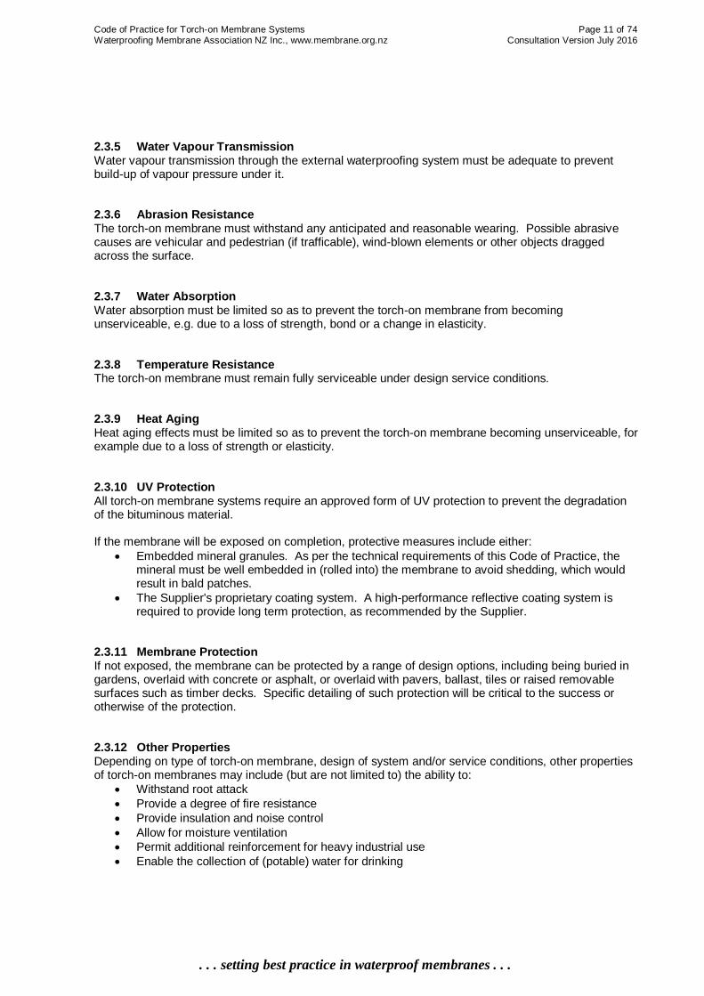
2.3.5 Water Vapour Transmission Water vapour transmission through the external waterproofing system must be adequate to prevent build-up of vapour pressure under it. 2.3.6 Abrasion Resistance The torch-on membrane must withstand any anticipated and reasonable wearing. Possible abrasive causes are vehicular and pedestrian (if trafficable), wind-blown elements or other objects dragged across the surface. 2.3.7 Water Absorption Water absorption must be limited so as to prevent the torch-on membrane from becoming unserviceable, e.g. due to a loss of strength, bond or a change in elasticity. 2.3.8 Temperature Resistance The torch-on membrane must remain fully serviceable under design service conditions. 2.3.9 Heat Aging Heat aging effects must be limited so as to prevent the torch-on membrane becoming unserviceable, for example due to a loss of strength or elasticity. 2.3.10 UV Protection All torch-on membrane systems require an approved form of UV protection to prevent the degradation of the bituminous material. If the membrane will be exposed on completion, protective measures include either:
Embedded mineral granules. As per the technical requirements of this Code of Practice, the mineral must be well embedded in (rolled into) the membrane to avoid shedding, which would result in bald patches.
The Supplier's proprietary coating system. A high-performance reflective coating system is required to provide long term protection, as recommended by the Supplier.
2.3.11 Membrane Protection If not exposed, the membrane can be protected by a range of design options, including being buried in gardens, overlaid with concrete or asphalt, or overlaid with pavers, ballast, tiles or raised removable surfaces such as timber decks. Specific detailing of such protection will be critical to the success or otherwise of the protection. 2.3.12 Other Properties Depending on type of torch-on membrane, design of system and/or service conditions, other properties of torch-on membranes may include (but are not limited to) the ability to:
Withstand root attack
Provide a degree of fire resistance
Provide insulation and noise control
Allow for moisture ventilation
Permit additional reinforcement for heavy industrial use
Enable the collection of (potable) water for drinking

Code of Practice for Torch-on Membrane Systems Page 12 of 74 Waterproofing Membrane Association NZ Inc., www.membrane.org.nz Consultation Version July 2016
. . . setting best practice in waterproof membranes . . .
2.4 Durability and Maintenance The durability requirements under the Building Code Clause B2 Durability are that:
The membrane cladding system must be sufficiently durable to ensure that the building, without reconstruction or major renovation and with normal maintenance, continues to satisfy the performance requirements.
The torch-on membrane system must remain weathertight (as required by Clause E2 External Moisture) and perform as required to provide not less than 15 years' durability (as required by Clause B2 Durability).
When a protective coating over a torch-on membrane is used, it is intended to provide protection for a minimum of 5 years. Therefore, to meet the 15-year durability, the torch-on membrane system must be checked, maintained and re-surfaced within a 5- to 7-year cycle. Refer to Chapter 7 (Maintenance).
2.5 Product Performance The manufacture of the reinforced modified bituminous membrane must be quality controlled throughout the complete process from raw materials to the finish, including research and development. Quality controlled manufacturing must be based on constant and regular internal self-checks and monitored by an issuing authority. The Manufacturer and the internal testing department must be ISO 9001 certified.
2.6 Types of Torch-on Membranes Modified reinforced bitumen membranes as defined below can be applied either by torching on, setting in a liquid bedding compound or with a "peel and stick" self-adhesive on the underside of the sheet. There is a wide range of torch-on membranes able to be used in a wide range of combinations. Typical systems are set out in Table 5. Each combination meets a specific situation requirement, differing in composition (SBS, APP and composite), type and weight of reinforcement, surface finishes and profiles, properties and characteristics. This section covers the range of membranes that are suitable for New Zealand conditions; first the standard products most commonly used (2.6.1 to 2.6.10), then membranes with special properties or uses (2.6.20 to 2.6.25). Designers should check with the Supplier that all torch-on membrane components are compatible. The most frequently used membranes in New Zealand are listed in Table 6. Other standard membranes or custom-designed membranes are available or are being developed with new advanced resins, reinforcement and finishes for specific design requirements. 2.6.1 Perforated Vent Sheet (V1) A thin fibreglass reinforced torch-on membrane which has a regular pattern of 20-40mm diameter holes (perforations) and is loose-laid over the substrate. When the next membrane layer is applied, the bitumen runs through the perforations and adheres to the substrate. The bond to the substrate surface is approximately 30%, thereby providing air spaces for moisture to dissipate. This perforated vent sheet offers no waterproofing in itself and therefore is not considered to be part of the waterproofing membrane system.

Code of Practice for Torch-on Membrane Systems Page 13 of 74 Waterproofing Membrane Association NZ Inc., www.membrane.org.nz Consultation Version July 2016
. . . setting best practice in waterproof membranes . . .
There is a wide range of vent sheets available. If thinner than 2.0mm or only mechanically fastened throughout the sheet, then like the perforated vent sheet, it is not considered to form a layer of the waterproofing system. 2.6.2 Vent Sheet (B1) Vent sheets of SBS or APP, polyester or glass reinforced 50-120+ g/m
2 with overlapped seams and
end-welded are considered a separate layer in a multi-layered torch-on membrane system. Venting can be achieved by being mechanically fastened within the laps, by being spot-adhered, or having a profiled or fleeced back. An APP glass fibre reinforced membrane 2.0mm minimum, mechanically fastened under overlap or spot adhered, can be used as the base sheet for a ventilation system. The underside of the vent sheet can vary from fleece (non or partial bonding), undulating either in ridges, blobs or strips of soft bitumen to provide partial bond (approximately 60%) and moisture dissipation. 2.6.3 Base Sheet (B2, B3, B4) The base sheet forms the first layer of a multi-layered torch-on membrane system. Base sheets range in thickness from 2.0-4.0mm, comprised of either SBS or APP bitumen and reinforced by spun-bound polyester cloth, fibreglass or composition of both at weight of 120+ g/m
2.
They are torched on or adhesive-bonded fully adhered (unless of a vent type), overlapped and welded at side seams and ends. Some have a thermal self-adhesive underside for a full bond or a partially vented bond and achieve total bond when the cap sheet is torched on. Other types of base sheets are mechanically fastened, being specifically designed with stabilised reinforcement to ensure dimensional stability and to avoid wrinkling. 2.6.4 Cap Sheet Smooth (C1, C2) A cap sheet of SBS- or APP-modified bitumen membrane with a thickness of 3-5mm is reinforced with non-woven spun-bound polyester fabric with or without fibreglass strands at a weight of 180+ g/m
2 with
a top surface finish of fine sand, talc or surfacing cloth that, if left exposed, will require over-coating. 2.6.5 Cap Sheet Mineral (C3, C4) A cap sheet of SBS- or APP-modified bitumen membrane with a film thickness of 4-5mm (although more commonly referred to by weight of 3.5-4.5kg/m²) is reinforced with non-woven spun-bound polyester fabric with a top surface of mineral granules embedded in the bitumen. The selvedge edge (seams) is smooth (not coated in mineral) to allow full bitumen-to-bitumen bonding. 2.6.6 Re-roof Cap Sheet (SP1) This is a variation of the mineral-faced cap sheet, with a vented under-layer to permit any trapped moisture in the substrate, under or within the existing membrane, to dissipate. The underside of the vent sheet can be either fleece-backed (non- or partially-bonded), or undulating with ridges, blobs or strips of soft bitumen to provide partial bonding (approximately 60%) to aid moisture dissipation. 2.6.7 Metal-Faced Cap Sheet (SP2) This cap sheet is an SBS-modified bitumen membrane of film build 3-4mm, reinforced with a polyester fabric and with a profiled face pre-finished with a fine metal foil sheeting.

Code of Practice for Torch-on Membrane Systems Page 14 of 74 Waterproofing Membrane Association NZ Inc., www.membrane.org.nz Consultation Version July 2016
. . . setting best practice in waterproof membranes . . .
Metal-faced cap sheets can only be applied over a multi-sheet torch-on membrane system of a film build not less than 6mm total. 2.6.8 Asphalt Overlay (SP3) Sometimes referred to as "hot mix", asphalt can be laid over specially formulated torch-on membranes reinforced by spun-bound polyester cloth, fibreglass or composition of both at weight of 200+ g/m
2 with
good heat-resistant properties. Asphalt overlay provides a durable and highly trafficable vehicular surface. 2.6.9 Mechanical Fixing (SP4) Mechanically fixed base sheets are required where torching on will not be sufficient to ensure adhesion to the substrate. These base layers are required in all higher wind situations, i.e. where wind speed exceeds 38m/s. See Section 3.1 (Membrane Selection) for details. Mechanically-fixed base sheets are also required for fleeced-back membranes, which are only partially adhesion-bonded to the substrate and under laps for improved fastening of membrane to substrate. 2.6.10 Adhesive-bonded (SP5) Similar to mechanical fixing, in some situations torching on a base layer is not possible – for instance if over polystyrene or some other substrate that will be affected by high temperatures or a naked flame. A bitumen compound is used for full or partial adhesion of the membrane to the substrate, a membrane to foam panels, bedding in of foam panels to the substrate or where the use of a naked flame is not recommended. Note: Item numbers 2.6.11 to 2.6.19 have not been used in this Edition, and are reserved for possible future product inclusions. 2.6.20 Fire-retardant Membranes (SP6) Modified bituminous membranes that incorporate non-toxic flame retardant additives are reinforced with a non-woven spun-bound polyester fabric of 160+ g/m² weight to a film thickness of 4mm or 4.5kg/m², and finished with protective minerals. 2.6.21 Garden (Root-resistant) Membranes (SP7) Modified bituminous membranes that incorporate an anti-root additive are reinforced with non-woven spun-bound polyester fabric of 180+ g/m² with a smooth finish. These are designed to be used as the cap sheet in a multi-layered system for roof gardens or garden boxes etc. 2.6.22 Composite Membranes (C4) Two or more bituminous components are combined in the factory to create one single torch-on membrane with an overall thickness of 4-5mm, with a smooth or mineral finish. This usually has an SBS under-layer with reinforcement (in the centre) of non-woven spun-bound polyester fabric with fibreglass strands or matting at 180+ g/m² and a topping layer of an APP-modified bitumen. 2.6.23 Protection and Drainage Membrane A modified reinforced membrane which has a profiled top face, usually of raised round indentations or dimples, which can provide protection to the waterproof membrane system. It can also aid drainage or fused adhesion for an overlay system.

Code of Practice for Torch-on Membrane Systems Page 15 of 74 Waterproofing Membrane Association NZ Inc., www.membrane.org.nz Consultation Version July 2016
. . . setting best practice in waterproof membranes . . .
2.6.24 Sound-deadening Membrane A modified reinforced membrane which incorporates a high-build fleece (or other material) to its underside to provide sound deadening properties when used in a double-layer membrane or an inverted roof system. Any such membrane will only be part of a total sound-deadening system. 2.6.25 Surface Finish The exposed face of torch-on membranes in New Zealand is usually pre-finished with either a mineral-embedded, plain (fine sand or talcum surface) or metal face. After installation, a protective coating must be applied to plain membranes as a component of the system to protect against the effects of UV light and weathering.

Code of Practice for Torch-on Membrane Systems Page 16 of 74 Waterproofing Membrane Association NZ Inc., www.membrane.org.nz Consultation Version July 2016
. . . setting best practice in waterproof membranes . . .
Table 5 – Typical Torch-on Membrane Systems
A. Exposed Membrane Systems:
A1 Single Layer
Concrete surface roof, no traffic with an APP and/or SBS 4-5mm thick membrane (C2, C3 or C4).
A2 Double Layer All double layer systems must be a minimum of 6mm in total.
Concrete surface roof or deck subject to frequent pedestrian traffic with a 2-4mm SBS or APP Base Sheet (B2 or B3 or B4) and overlaid with 3-5mm APP Cap Sheet (C2, C3 or C4).
Plywood surface deck or large roof subjected to infrequent pedestrian traffic with a 2-4mm Base Sheet (B2 or B3 or B4) and overlaid with 3-5mm APP Membrane (C2, C3 or C4).
Plywood surface roof/deck subjected to frequent pedestrian traffic with a 2-4mm Base Sheet (B2 or B3 or B4) and overlaid with 4-5mm APP Membrane Cap Sheet (C3 or C4).
A3 Triple Layer All triple layer systems must be a minimum of 7mm in total.
Concrete or plywood substrate that incorporates a Vent Sheet (B1) overlaid with a 2-4mm Base Sheet (B2 or B3 or B4) and finished with 3-5mm APP membrane Cap Sheet (C2, C3 and C4).
B. Non-Exposed Membrane Systems:
The substrate must provide the required falls if the membrane is completely overlaid with concrete, asphalt, tiles, pavers, duckboards etc. B1 Single Layer
Concrete surface with a 4mm APP or 4-5mm SBS membrane (C2, C3 or C4). B2 Double Layer
Concrete or plywood surface with either a vented Base (B1) or 2-4mm SBS or APP Base Sheet (B2 or B3 or B4) and finished with 3-5mm SBS or APP Cap Sheet (C2, C3 or C4), to give a minimum total thickness of 6mm.
B3 Triple Layer
Concrete or plywood surface with a Vent Sheet (B1), Base Sheet (B2 or B3 or B4) and finished with a Cap Sheet (C2, C3 or C4).
Note: Where required, the above systems could incorporate a perforated Vent Sheet (V1) or a non-overlapped welded joint Vent Sheet thinner than 2mm to dissipate moisture vapour. This additional layer does not constitute another layer in terms of defining single-, double- or triple-layered membranes.

Code of Practice for Torch-on Membrane Systems Page 17 of 74 Waterproofing Membrane Association NZ Inc., www.membrane.org.nz Consultation Version July 2016
. . . setting best practice in waterproof membranes . . .
3. Membrane Selection This chapter is primarily written for the Designer. It sets out the optimum membrane to select for a given situation.
3.0 General The most important factor to be considered when selecting a torch-on membrane roofing system is the specific use to which the roof or deck will be put. Used together, Table 6 and Figure 1 will suggest a torch-on membrane system to provide the necessary protection from water or moisture ingress for the given situation, where:
Table 6 –Torch-on Membrane Layers Available in New Zealand lists the possible torch-on membrane system layers or combinations thereof.
Figure 1 – System Selection Flow Chart gives the major selection criteria of site and project specific situations in conjunction.
3.1 Material Selection The membrane system selected from Figure 1 is the minimum "fit-for-purpose" system. However, the Designer, Supplier, Applicator or Building Owner may recommend, suggest or request a more robust system. When a torch-on membrane system is determined from Figure 1, select the component layer(s) from Table 6 according to the system properties required. In most selection situations, the more layers there are in the complete torch-on membrane system, the better the waterproofing protection. Some of the factors to be considered include:
Wind Zone/Speed A potential failure of torch-on membrane systems is delamination from the substrate because of wind uplift.
o For buildings up to 10m in height and wind speeds up to 55m/s, refer to NZS3604:2011 Section 5 (Bracing Design) to determine the wind zone in different areas of New Zealand.
o For buildings over 10m in height and/or for wind speeds in excess of 55m/s, refer to AS/NZS1170.2:2011 for wind load calculations to enable specific design to be undertaken.
Defined Wind Situations
o For Low to Medium wind zones (less than 38m/s) both layers of a two-layer membrane system shall be fully adhesive or torch-bonded: base layer to the substrate, and cap sheet to the base layer.
o For High wind zones (38-44m/s) there must be additional mechanical fixing at all perimeter edges and ridges, on roofs both with and without parapets, with Supplier-nominated fixings at 300mm minimum centres and with fixings extending perpendicular to the perimeter for 0.9m at all laps.
o For all Very High or greater wind zones (greater than 44m/s) the base layer must be mechanically fixed to the substrate with Supplier-nominated fixings, using a fixing pattern stipulated in the building-specific wind load design from the Supplier and confirmed by the Designer, which must be based on AS/NZS1170.2:2011 design information. The Designer must also ensure that the substrate design is specific and appropriate for the wind-load conditions.
____________________________________________________________________________________________
Acronyms: APAO = Alpha Olefins; APP = atactic polypropylene; HD-EPS = high density expanded polystyrene foam; SBS =
styrene-butadiene-styrene; UV = ultra violet; XPS = extruded polystyrene foam

Code of Practice for Torch-on Membrane Systems Page 18 of 74 Waterproofing Membrane Association NZ Inc., www.membrane.org.nz Consultation Version July 2016
. . . setting best practice in waterproof membranes . . .
Amount of expected foot traffic Direct foot traffic on any torch-on membrane system increases the possibility of damage to the membrane. Permanent protection must be used in high traffic situations.
Amount of expected vehicular traffic For situations where vehicular traffic is expected, it must be protected.
Roof system A roof can be either a cold, insulated or inverted roof. Each roof system will have different substrate, ventilation and fixing requirements. Refer to Section 3.8.
Size of deck/roof Care and attention to detail is required for any area to be covered by a torch-on membrane system. However, a larger roof/deck (greater than 40m
2 as limited in E2/AS1) will require
additional detailing and care during installation. It is more likely that a large deck/roof will have many service penetrations, plant fixed on the roof, a greater number of scuppers, more membrane joints, possibly expansion or control joints for either the torch-on membrane system or the structural support under the torch-on membrane.
Temperature variation or prevailing weather conditions Bitumen becomes more viscous in warmer weather and more brittle in colder weather. Modified bitumens such as SBS and APP offer specific properties designed to accommodate such requirements, i.e. SBS in freeze-thaw conditions and APP in hot climates. Consult the Supplier to determine which composition system will work best.
Snow loadings Site-specific pitch and roof design will be required, which may include snow-boards and mechanical fixings.
Roof slope For roof slopes greater than 10° above the horizontal, full adhesion bonding between all layers of a torch-on membrane system must always be used.
Chemical environment Torch-on membranes may be unsuitable in the presence of hydrocarbons, oils or fats, which will act aggressively to break down the bituminous composition and lead to the eventual failure of the torch-on membrane system.
Substrate This Code of Practice considers concrete or treated plywood substrates.
Existing roof The type and age of the torch-on membrane already installed.
Colour Bituminous torch-on membranes come in a variety of colours. Where there is a requirement for a coloured finish, this will be accomplished either by the application of a proprietary surface coating, finish or the use of a coloured mineral granule. If heat build-up is of concern, the use of a light colour should be considered. General roof or house paint must not be used for coating modified bitumen surfaces.
Inspection and maintenance As an integral part of the waterproofing system of the building, maintenance of the torch-on membrane systems must be provided for as part of the overall maintenance programme for the whole building. Visual inspections to determine any required repairs and/or preventive maintenance must be carried out at least annually. Areas subject to changing seasonal conditions, e.g. autumnal leaf build-up may require more regular inspections.

Code of Practice for Torch-on Membrane Systems Page 19 of 74 Waterproofing Membrane Association NZ Inc., www.membrane.org.nz Consultation Version July 2016
. . . setting best practice in waterproof membranes . . .
Potable water A torch-on membrane can be used for the collection of potable water if over-coated with a coating specifically designed for that purpose, or if the membrane has been developed and proven for this use.
Code of Practice for Torch-on Membrane Systems Page 20 of 74 Waterproofing Membrane Association NZ Inc., www.membrane.org.nz Consultation Version July 2016
. . . setting best practice in waterproof membranes . . .
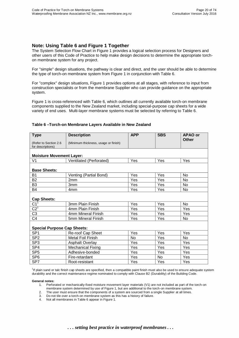
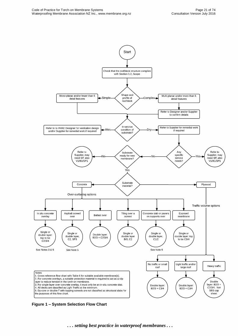
Note: Using Table 6 and Figure 1 Together The System Selection Flow Chart in Figure 1 provides a logical selection process for Designers and other users of this Code of Practice to help make design decisions to determine the appropriate torch-on membrane system for any project. For "simple" design situations, the pathway is clear and direct, and the user should be able to determine the type of torch-on membrane system from Figure 1 in conjunction with Table 6. For "complex" design situations, Figure 1 provides options at all stages, with reference to input from construction specialists or from the membrane Supplier who can provide guidance on the appropriate system. Figure 1 is cross-referenced with Table 6, which outlines all currently available torch-on membrane components supplied to the New Zealand market, including special-purpose cap sheets for a wide variety of end uses. Multi-layer membrane systems must be selected by referring to Table 6. Table 6 –Torch-on Membrane Layers Available in New Zealand
Type (Refer to Section 2.6 for descriptions)
Description (Minimum thickness, usage or finish)
APP SBS APAO or Other
Moisture Movement Layer:
V1 Ventilated (Perforated) Yes Yes Yes
Base Sheets:
B1 Venting (Partial Bond) Yes Yes No
B2 2mm Yes Yes No
B3 3mm Yes Yes No
B4 4mm Yes Yes No
Cap Sheets:
C11 3mm Plain Finish Yes Yes No
C21 4mm Plain Finish Yes Yes Yes
C3 4mm Mineral Finish Yes Yes Yes
C4 5mm Mineral Finish Yes Yes No
Special Purpose Cap Sheets:
SP1 Re-roof Cap Sheet Yes Yes Yes
SP2 Metal Foil Finish No Yes No
SP3 Asphalt Overlay Yes Yes Yes
SP4 Mechanical Fixing Yes Yes Yes
SP5 Adhesive-bonded Yes Yes Yes
SP6 Fire-retardant Yes No Yes SP7 Root-resistant Yes Yes Yes
1If plain sand or talc finish cap sheets are specified, then a compatible paint finish must also be used to ensure adequate system
durability and the correct maintenance regime nominated to comply with Clause B2 (Durability) of the Building Code.
General notes: 1. Perforated or mechanically-fixed moisture movement layer materials (V1) are not included as part of the torch-on
membrane system determined by use of Figure 1, but are additional to the torch-on membrane system.
2. The user must ensure that the components of a system are sourced from a single Supplier at all times. 3. Do not tile over a torch-on membrane system as this has a history of failure. 4. Not all membranes in Table 6 appear in Figure 1.
Code of Practice for Torch-on Membrane Systems Page 21 of 74 Waterproofing Membrane Association NZ Inc., www.membrane.org.nz Consultation Version July 2016
. . . setting best practice in waterproof membranes . . .
Figure 1 – System Selection Flow Chart

Code of Practice for Torch-on Membrane Systems Page 22 of 74 Waterproofing Membrane Association NZ Inc., www.membrane.org.nz Consultation Version July 2016
. . . setting best practice in waterproof membranes . . .
3.2 Multiple-layered Systems To provide additional protection and long-term waterproofing, a multiple-layered membrane system may be specified. In a two-layered system, each sheet must be fully waterproof in its own right, thus the following sheets cannot be considered to form part of the two-layered system:
A thixotropic bedding compound
A perforated vent sheet
A mechanically-fixed sheet
3.3 Coating and Protection Mineral-finish membranes provide inherent UV protection provided that the mineral granules themselves remain firmly embedded in the membrane and do not normally require coating. Plain-finish torch-on membranes as supplied from the Supplier must be coated to provide various properties or combinations thereof as required, including to:
Provide UV protection
Reduce heat absorption
Provide wider colour selection
Enable a specific design appearance or colour, with a light reflectance value of greater than 40
Enable the collection of potable water After installation, the membrane must be left for a suitable period as recommended by the Supplier to allow for the release of any installation tension and for any oxidisation of the outermost face to occur. Following this, the torch-on membrane system must be checked and any maintenance or repair work carried out. Then the membrane should be cleaned ready for any final coating.
Membranes are to be coated in accordance with the Supplier's recommendations. Low slope structures must be coated with suitable immersion-resistant type paint.
Mineral-finish membranes may also be coated. Coatings must be kept clean and free of algae infestation. Coatings may require re-coating every 5-7 years, depending on the local conditions and the Supplier's recommendation.
3.4 Over-Surfacing There are times when the torch-on membrane system is over-surfaced for various purposes that can involve a wide range of other systems or materials. This section covers the majority of these situations, and addresses the general membrane selection, installation and protection requirements. Some examples are shown below. Refer to the Supplier's documentation to develop the building consent documentation.
NEVER DIRECT-TILE OVER A TORCH-ON MEMBRANE SYSTEM
3.4.1 In Situ Concrete For situations such as car parks, a concrete screed can be laid over a membrane system protected by a slip layer such as a heavy gauge polythene sheet.

Code of Practice for Torch-on Membrane Systems Page 23 of 74 Waterproofing Membrane Association NZ Inc., www.membrane.org.nz Consultation Version July 2016
. . . setting best practice in waterproof membranes . . .
3.4.2 Asphalt Screed An alternative option for car parks is to lay an asphalt screed over the membrane system. The membrane system must be protected by a slip layer such as a heavy gauge polythene sheet. The membrane Supplier must be contacted regarding detailing for this type of application, particularly on ramped areas where installation slip-layer creep may occur. 3.4.3 Ballast Over Ballast is broadcast over the membrane to improve UV protection, durability and trafficable. It must be laid over a protection drainage sheet/pad or geo-textile. Ballasted roofs are normally surrounded by a parapet. 3.4.4 Tiling Over a Screed If a tile decking over a screed is specified, the membrane must be protected with a suitable release layer such as heavy gauge polythene. Then a minimum 30mm cement reinforced screed is installed and left to cure before the tiles are laid. The screed and the tiles must incorporate expansion joints at maximum 3m x 3m grid centres and at the perimeter of the deck.
3.5 Concrete Over or Raised/Removable Surfaces Concrete is often poured over a membrane as the final surface, e.g. in car parks. The concrete design is outside the scope of this Code of Practice, but the concrete design must be made in conjunction with the Supplier to ensure compatibility of materials and the functionality of the design. Removable surfaces can also be used over a torch-on membrane system. Usually concrete pavers, they are supported by either proprietary systems (sometimes called a "chair" or a "pedestal") or they can be custom-designed. Such systems must be designed to allow water to pass through and are not part of the waterproofing system. They provide a protection layer by eliminating any direct traffic to the membrane, with their key principles being that:
There must be some removable panels to enable access to the membrane itself for future maintenance or to clear any debris build-up, particularly in and around drains.
The finished surface of the pavers will allow water to pass through, usually a 5mm gap between pavers.
The finished surface is well-supported, such that it will not deflect under the expected normal traffic loads.
The support mechanisms will not damage the torch-on membrane system, either by having a great enough number of individual supports or by the use of a support system that sufficiently spreads the load so that there are no unacceptable point loads.
Any support component will not penetrate the torch-on membrane, unless specifically designed and detailed to do so.
There is a 12mm minimum gap between the pavers at the edge and any adjoining wall or balustrade.
3.6 Exposed Membranes If the membrane is to be left exposed, it must have a UV- and weather-resistant cap sheet, being either a pre-finished mineral required for maximum maintenance-free durability or a coating over a plain finish.

Code of Practice for Torch-on Membrane Systems Page 24 of 74 Waterproofing Membrane Association NZ Inc., www.membrane.org.nz Consultation Version July 2016
. . . setting best practice in waterproof membranes . . .
3.7 Accessories Accessories (often called ancillary products) should be sourced from the membrane Supplier with the membrane to create a complete system. Other than box sumps in gutters that can be pre-formed in the substrate, all other accessories are purpose-designed or proprietary, and constructed from non-ferrous metal or a composite material, e.g. thermoplastic, rubber or similar. Such accessories or ancillary products should be a single component. Where practical, the flanges of all accessories (other than air vents) should be fitted, mechanically fixed and recessed into the substrate to create a level surface for the membrane to cover over, unless under-flashed to sandwich the flange between. Typical roof accessories should be rebated into substrates where possible, and may include:
Box sumps – placed in gutter and roofs at low points. These are pre-formed in square or rectangular shapes, with one large drain. Some models also incorporate overflows.
Scuppers – often referred to as parapet box outlets. These are pre-formed with flanges and a pipe or tongue to go through the parapet into an external rainwater head or a downpipe.
Overflows – a variety of pre-formed models and shapes are available. They should be installed at a height to allow excess water to be drained away safely rather than flow into the building structure. They are very often standpipes with the top level set at the high point of the drained area and therefore well below the highest flashing or upstand level.
Drains – a range of purpose-designed drains installed in the roof and deck substrate allow surface water to drain away. The most common are often referred to as a "dropper" and are pre-formed with a flange, a clamp ring and a non-return tongue that fits into the downpipe.
Drain grilles – often referred to as leaf guards. These are purpose-designed and manufactured from non-ferrous metal or a composite material, either loose fitted or held in place by a flange.
Air-vents – these can be cone type (mushroom-shaped) or low profile, both with caps to allow moisture vapour to dissipate whilst preventing rainwater entry.
Other accessories supplied for use over torch-on membranes may include:
Paver supports, duckboards, support pads – purpose-designed, these are pre-formed out of thermoplastic rubber to provide support for concrete pavers or timber framing for catwalks or duck boarding. These pads provide protection to the membrane and permit water drainage.
Walkway matting – often produced out of recycled rubber granules, the matting provides protection to the membranes from maintenance traffic and incorporates other features, such as sound-deadening acoustic and anti-slip properties.
Protection or drainage mats – there is a range of products available, from profiled HDPE protection sheets to purposely designed drainage cores incorporating geo-textile.
Note: The shaded Sections 3.8 to 3.10 below are introductory commentary only, and will be developed fully in future publications. They require specialist design, and are outside the scope of this Code of Practice. Detailed design and specifications must be developed; refer to the Supplier for particular information to support the design.
3.8 Insulated Roof Membrane Assembly There are two insulated roof assemblies:
Insulated roof – where the membrane is above the insulation
Inverted roof – where the insulation is placed above the membrane system and then protected by an over-surfacing system.
For both systems:
The panels should be installed in an interlocking brick-like pattern so that there are no long joins along which the membrane could tear.
Where installed, concrete screeds must only be placed over a torch-on membrane

Code of Practice for Torch-on Membrane Systems Page 25 of 74 Waterproofing Membrane Association NZ Inc., www.membrane.org.nz Consultation Version July 2016
. . . setting best practice in waterproof membranes . . .
system that has been protected with polythene sheet, foam panels, XPS, HD-EPS or other suitable protection materials that act as a slip membrane to reduce tension on the torch-on membrane.
3.8.1 Insulated Roof
If the substrate is level, foam panels can be tapered to provide a uniform fall. If the substrate has been designed to provide a fall then the foam panels can all be the same thickness.
The panels can be directly fixed to the substrate by a mechanical fixing method or, if over a vapour base sheet, by a cold adhesive bed or with bituminous membranes designed for the purpose.
Any torch-on membrane system over foam panels must be a double layer: the first being a self-adhesive or cold-fix type to avoid the use of flame, and the cap sheet torched on. All laps must be heat-welded.
Some proprietary systems are available where a bituminous membrane is pre-attached to the foam insulation. These would be laid as per the Supplier's instructions with overlaps heat-welded, and then a cap sheet applied.
Roofs that involve foam insulation immediately under the membrane should be non-trafficable, other than for maintenance purposes.
3.8.2 Inverted Roof
This work is carried out by other trades and it is the responsibility of the Main Contractor to ensure that adequate protection of the membrane system is in place before the application of the other material.
3.9 Roof Gardens/Green Roofs A roof garden is where the membrane is over-laid with a drainage system, growing medium and plant matter. It may or may not include an insulation layer. For the membrane system itself, and in general:
For all roof gardens, the minimum torch-on membrane system must be a double-layered system to ensure watertightness. The top layer should be a membrane specifically designed for roof gardens that incorporates a root-resistant additive to resist root attack.
Ensure all drainage outlets are mechanically fixed, and that leaf guards are installed and wrapped in geo-textile.
Roof garden membranes to both the floors and walls must be protected from mechanical damage, e.g. from spade/shovel strike.
A free-draining/protective layer should be installed between the membrane and the body of the garden.
3.10 Vehicle Decks Torch-on membranes can be used as the waterproofing layer for exposed vehicle decks.
The membrane must always be over-laid with a protective wearing course such as asphaltic concrete or Portland cement concrete laid thick enough or reinforced to maintain its integrity under normal traffic usage.
The wearing course may be either bonded to the membrane which will require a specific membrane design, or laid over a slip-sheet on the membrane – in which case it is regarded as a floating slab. In such circumstances, unless the membrane has been specifically designed, a two-layer system must always be used.

Code of Practice for Torch-on Membrane Systems Page 26 of 74 Waterproofing Membrane Association NZ Inc., www.membrane.org.nz Consultation Version July 2016
. . . setting best practice in waterproof membranes . . .
4. Design This chapter is primarily written for the Designer and Applicator. It will also assist the Main Contractor and Building Consent Authority. It addresses the substrate and illustrates typical installation detailing.
4.0 General 4.0.1 Wind Uplift For all Very High or greater wind zones (greater than 44m/s), the base layer must be mechanically fixed to the substrate with appropriate fixings, using a fixing pattern based on the building-specific wind-load design. This is provided by the Supplier and confirmed by the Designer, and must be based on AS/NZS1170.2:2011 design information. The Designer must also ensure that the substrate design is specific and appropriate for the wind-load conditions. For all buildings in these wind zones the type, layout and frequency of the fixing is stipulated in a design specific to each building, based on building shape, location, roof plan, profile and substrate. 4.0.2 Falls Torch-on membrane roofing systems are often considered to be the cure-all material where it is not possible to provide a fall or slope to a roof plane or deck. While torch-on membranes will keep water out where there is minimal fall, it is well recognised that providing adequate fall to the roof area enhances the serviceable life of the membrane system, and minimises ponding and the risk of moisture ingress into the structure. For construction up to 10m in height, this Code of Practice requires the following minimum falls:
The minimum fall for a roof is 2°, which is equivalent to 1:30
The minimum fall for a deck is 1.5°, which is equivalent to 1:40
The minimum fall for a gutter is 0.5°, which is equivalent to 1:100
For construction above 10m in height, this Code of Practice requires the following minimum falls:
The minimum fall for a roof is 1.0°, which is equivalent to 1:60
The minimum fall for a deck is 1.5°, which is equivalent to 1:40
The minimum fall for a gutter is 0.5°, which is equivalent to 1:100
All projects must be discussed between the Designer and Supplier to ensure adequate falls, taking into account factors such as:
Large span of the supporting structure
Possible creep or settlement of the supporting structure
Size or shape of a gutter which could require cross-laying of the membrane _________________________________________________________________________________________
Acronyms: APAO = Alpha Olefins; APP = atactic polypropylene; HD-EPS = high density expanded polystyrene foam; SBS = styrene-butadiene-styrene; CCA = copper chrome arsenate; CuN = copper nitrate; HVAC = heating ventilation air-conditioning (Engineer) LOSP = light organic solvent preservative; XPS = extruded polystyrene foam
Code of Practice for Torch-on Membrane Systems Page 27 of 74 Waterproofing Membrane Association NZ Inc., www.membrane.org.nz Consultation Version July 2016
. . . setting best practice in waterproof membranes . . .
4.1 Substrate Requirements 4.1.0 General The substrate onto which the torch-on membrane system is to be laid must be:
Sufficiently rigid in combination with the structure underneath (if a separate building element)
Dense and dimensionally stable to support the membrane system, insulation, surface protection and any mechanical plant or other item
Designed to incorporate the required falls, drains, sumps and outlets to ensure sufficient drainage, with sufficient movement/expansion joints in the substrate and structure.
The substrate selection and substrate structure design is the responsibility of the Designer. It is the responsibility of the Main Contractor to ensure that the designed falls are installed. 4.1.1 New Concrete Substrates Except for topping screeds, new concrete substrates are generally structural building elements in their own right. They must be designed and built to the Designer's design and specifications and the Building Code. If a curing agent is used, it must be removed by an abrasive method to ensure complete removal. Failure to do so can result in the failure of the adhesion of the torch-on membrane to the substrate surface. Concrete substrates must be laid to falls and incorporate coves to upstands and rounded corners, drainage outlets at low points and integral expansion joints. They must be finished with a wooden float or light broom to provide an even, open surface. The concrete surface finish must be either U2 wood-float or U3 steel trowel to NZS 3114. Steel-floated finishes will require captive blasting or grinding to permit penetration of the bitumen primer. There must be a minimum 28-day curing period of the concrete surface before a torch-on membrane is installed. 4.1.2 Existing Concrete Substrates Existing concrete substrates must be prepared and cleaned as per the Supplier's recommendations. Steps required for preparation may include:
If they are moss and/or mould infested, apply a killer solution, leave for 3 days and water-blast clean.
Grind off any nibs, flush out any hollows and/or imperfections.
Skim over (if required) to improve falls and provide satisfactory surface.
Install plaster fillets to upstands and chamfer all corners.
Mechanically repair unsatisfactory concrete surfaces to a suitable standard for membrane application.
Ensure the outlet(s) is/are at the lowest point and adequate in number.
Saw cut any movement cracks and fill with a pliable sealant.
Provide expansion joints on large roofs. 4.1.3 Cementitious Screeds
Where a reinforced concrete roof is to be overlaid with a concrete or plaster screed to provide falls, the screed should be laid and finished in accordance with NZS 3114.
The structure must be designed to accommodate the roofing and waterproofing loads.
The existing concrete is to be prepared and cleaned to ensure good adhesion of the new screed.

Code of Practice for Torch-on Membrane Systems Page 28 of 74 Waterproofing Membrane Association NZ Inc., www.membrane.org.nz Consultation Version July 2016
. . . setting best practice in waterproof membranes . . .
The new screed surface is to incorporate the required falls and be wood-floated to provide an even surface free of hollows, ridges or nibs. The thickness of the screed will determine the curing period required before application of the torch-on membrane system.
4.1.4 Plywood 4.1.4.0 General
Plywood must be branded to comply with the joint Australian/New Zealand Standard AS/NZS 2269:2004 and the Building Code requirements.
The top surface of the plywood must be sanded and plugged, to a minimum standard of C-D. 4.1.4.1 Treatment
Plywood substrate for the installation of a torch-on membrane system must be treated (CCA) H3.2 grade.
LOSP- or CuN-treated plywood must not be used as these will cause membrane adhesion problems.
4.1.4.2 Moisture Content The moisture content of plywood prior to priming must not be higher than 20%. During winter, pre-priming of the top surface and edges is advisable. Otherwise, plywood must be primed on the same day as installation. 4.1.4.3 Support Spacing for Plywood Substrates If a torch-on membrane system has a plywood substrate, it must meet the following minimum support dimensions given in Table 7, where:
"Roof" means an area designed for infrequent traffic
"Deck" means a contained trafficable area Table 7 – Plywood Design Chart: Minimum Plywood Thickness
Multiple Torch-on Membrane Layers
Roof Support 600mm x 600mm maximum
Deck Support 400mm x 400mm maximum
Minimum Plywood Thickness 17mm 20mm
4.1.4.4 Plywood Layout
Plywood must be installed across the joists, in a brick-like pattern, and with the face grain of the plywood all in the same direction.
The plywood sheets must be tight-butted with all edges of the sheets fully supported.
At least every 3rd row of nogs, dwangs or blocking must be full depth to reduce any twisting in the purlin/joist unless ceiling battens are installed.
4.1.4.5 Fixings
There must be solid blocking under all edges of the plywood substrate.
The plywood must be glued and mechanically fixed with counter-sunk Grade 316 stainless steel 10 gauge screws at a length approximately 3 times that of the thickness of the plywood.
Screw spacing must be at 150mm centres at the perimeter of the sheet and 300mm through the body of the sheet.
All sheets must be fixed from the centre out to reduce bowing. 4.1.4.6 Corners
All leading edges of plywood are to be chamfered with minimum 5mm radiused corners (as per E2/AS1) where the membrane is to be flashed.
All internal corners are to have timber fillets, to be minimum 20 x 20mm and H3.2 treated. If preferred, proprietary bitumen fillets can also be used.

Code of Practice for Torch-on Membrane Systems Page 29 of 74 Waterproofing Membrane Association NZ Inc., www.membrane.org.nz Consultation Version July 2016
. . . setting best practice in waterproof membranes . . .
4.1.5 Mechanical Fixings for Wind Uplift Mechanical fixings for membrane systems comprise two elements:
A shank which penetrates and grips the substrate to prevent pull-out because of wind uplift
A pressure distribution plate or integral head to distribute the effect of wind uplift from the shank to the membrane.
Fixings specific to both concrete and timber/plywood substrates are available as a component of a Supplier's membrane system. For all Very High or greater wind zones, in accordance with NZS1170.2:2011, the building-specific wind uplift design for the membrane installation including fixing type and layout must be provided by the Supplier and the design confirmed by the Designer. The Supplier's design must be in accordance with the requirements of the Building Code and will be based on the design information specific to the fixings used.
Note - The shaded Section 4.2 below is introductory commentary only, and will be developed fully in future publications. These systems require specialist design, and are outside the scope of this Code of Practice. Detailed design and specifications must be developed in conjunction with the Supplier.
4.2 Insulated Roofing Membrane Assembly 4.2.0 General The use of insulation boards directly under a bituminous membrane is not common in New Zealand, but the practice is increasing to meet the demand for improved thermal performance within structures. Insulation is generally installed in new buildings in New Zealand within the roof space, either immediately above the ceiling with an air space to the roof, within the roof structure (e.g. between timber rafters) or on top of the roof structure. This Code of Practice specifically covers insulation boards where the insulation is immediately beneath the membrane, as the torch-on membrane is directly fixed to the insulation boards; or when the insulation boards are fixed over the top of the membrane and overlaid with pavers or ballast, commonly called an inverted roof. When insulation is incorporated in the roof structure design, the Designer should ensure that the dew point is to the outside of the membrane system. If a Designer is contemplating the use of insulation as described above, they must contact a Supplier to discuss the design of the system for the specific project. 4.2.1 Types of Insulation Boards The selection of the type of insulation board is dependent on design, location and the use of the roof. Soft or lofted insulations do not offer a sufficiently rigid or stable substrate for torch-on membranes. All insulation boards should be installed in fine weather, in stages and with the installation of the bituminous base sheet to prevent the entrapment of moisture. Some boards are tapered for drainage falls. The most common types of thermal insulation boards are:
Extruded polystyrene foam (XPS) – extruded closed cellular foam with uniform fine air cells that are not inter-connected; the foam is therefore water impermeable and dimensionally stable.
Polyurethane foam – insulation boards of rigid urethane, polyurethane or polyisocyanurate foam, with or without a fabric facing.

Code of Practice for Torch-on Membrane Systems Page 30 of 74 Waterproofing Membrane Association NZ Inc., www.membrane.org.nz Consultation Version July 2016
. . . setting best practice in waterproof membranes . . .
Cellular foamed glass – insulation boards which should have a density of 170-200kg/m
3. Some have a bitumen-reinforced fabric facing.
Compressed cork – boards consisting of granulated cork and natural gum that is compressed into slabs at a minimum density of 110kg/m
3.
Proprietary products – where bituminous membranes are adhered to the insulation boards as part of the manufacturing process. The advantage of this product is the insulation board and base sheet are installed in a single application.
4.2.2 Adhesion of Insulation Boards Insulation boards are adhered to the substrate or over a vapour barrier membrane by any of the following methods:
Cold adhesion
Bedding into a hot-melt adhesive or bitumen system
Mechanical fixing 4.2.3 Mechanical Fixing The design and location of the roof must be taken into consideration when assessing wind uplift resistance of the combined roof torch-on membrane system, to determine whether to mechanically attach the insulation boards using large (minimum 30mm) flat head fasteners. Purpose-selected fixings must be used. Refer to Section 3.1. 4.2.4 Vapour Barrier Where there is a requirement to control interstitial condensation within the roof structure and/or to permit moisture vapour from the substrate to dissipate, a vented vapour barrier membrane must be installed immediately above the substrate.
4.3 Existing Roof Torch-on Membranes Torch-on membranes are suitable for re-surfacing over existing bituminous roof torch-on membranes and structures. The Designer must decide whether to remove existing membrane components or to overlay them. Issues to be considered may include (but are not limited to):
Selection of the new torch-on membrane system
Compatibility of the proposed and existing systems
The type and condition of the existing surface
The type and condition of the existing substrate Overlaying has the following advantages:
The interior is at minimal risk of water ingress through the works.
Waste removal and disposal cost is minimised.
Contract period can be minimised. Overlaying has the following disadvantages:
The resultant roof loading may exceed the capacity of the structure.
Any entrapped moisture due to past water ingress must be dissipated before overlaying.
Finishing details may be compromised by an increased roof finish height.
Options for attachment of the new system may be restricted.
The proposed new material must be verified as being compatible with the existing material.
Existing falls must be accepted, unless new falls are created with other materials. Removal of the existing system provides maximum scope for correcting deficiencies in the existing design and thermal upgrading. It also widens the choice of attachment methods.

Code of Practice for Torch-on Membrane Systems Page 31 of 74 Waterproofing Membrane Association NZ Inc., www.membrane.org.nz Consultation Version July 2016
. . . setting best practice in waterproof membranes . . .
4.4 Design Detailing Figures 2-40 provide generic construction details. While the drawings are not to scale, they provide an installation overview to assist the Designer to understand the methodology of the membrane system for the purpose of providing plans, cross-section details and partial specifications for reinforced torch-on membrane system. 4.4.0 General While the Designer has overall responsibility for the design, there are some fundamental principles of design for torch-on membrane systems to be taken into account:
Torch-on membrane surfaces must have a fall.
The torch-on membrane system must be fully supported on a suitable substrate, which itself must be fully supported by the structure.
Roof spaces and habitable spaces must be well vented to ensure all moisture and water vapour is removed.
All outlets, droppers or overflows from the torch-on membrane system are to be supplied and installed by the torch-on membrane Applicator.
All end-laps must be at least 150mm.
All side-laps must be at least 80mm, or more if allowed by the membrane selvedge.
All membrane upstands must be at least 150mm or sufficient to provide a minimum 115mm cover behind the cladding system.
Full sheets must be used where possible.
The number of joints/laps must be kept to a minimum.
All flashings must be lapped over the under-layer.
Double- or triple-layer systems must have staggered laps.
Membranes for gutters should be laid longitudinally. The girth (overall width including under-laps to other roofing) of a gutter membrane should be designed as a module of the 1m-roll width (i.e. 0.5m, 1m, 1.5m, 2m), and any joints should be along the length of the gutter. In a double-layer gutter membrane the laps should be staggered to reduce unintended high points.
4.4.1 Ventilation 4.4.1.1 Cavity Ventilation Cavity ventilation for a roof space under a torch-on membrane substrate is the responsibility of the Designer to design and the Builder to construct. If required, an HVAC engineer would design the cavity ventilation system. Cross-flow ventilation is an important part of roof design, and can be achieved by soffit, parapet, ridge or roof vents. 4.4.1.2 Substrate Ventilation Substrate ventilation between the torch-on membrane and the substrate will be required where moisture is present in the building materials at the time of installation to minimise the risk of bubbles, blisters or wrinkling appearing on the surface of the torch-on membrane and to allow that moisture to dissipate. This also relates to the design of re-roof (over-laying) work. Refer to Section 7.7.2.
THE VENTILATION OF ROOF SPACES IS THE RESPONSIBILITY OF THE DESIGNER OR HVAC ENGINEER

Code of Practice for Torch-on Membrane Systems Page 32 of 74 Waterproofing Membrane Association NZ Inc., www.membrane.org.nz Consultation Version July 2016
. . . setting best practice in waterproof membranes . . .
4.5 Typical Installation Steps and Appropriate Design Detailing A typical torch-on membrane system may include some or all of the following installation steps. They are listed in an approximate order of work; however, a specific project may require or the Applicator may choose to do certain tasks in a different order. Suggested detailing and explanatory notes are also included. For all projects:
Plan the entire work programme before commencement.
Perform all detail work (gutters, edges, penetrations, etc.) before full sheet application. Possible installation steps and suggested detailing are as follows:
1) Install all droppers, parapet outlets, scuppers, sumps, overflows etc. in substrate recesses if practical, and bed-in to an under-flashing membrane. Use proprietary components where possible with stainless steel or other durable fixings.
The membrane must be flashed down into the drainage outlet, and heat-welded to the sides to prevent water moisture from tracking under the membrane and back into the structure.
In general, drainage from the membrane surface should be via gutters, channels or scuppers into rainwater heads and droppers. Ensure that they are positioned at the lowest point to give effective drainage.
Figure 2 – Typical roof/deck gutter outlet with rebated gutter flange
Figure 3 – Box sump with in-built overflow
Note: These figures are not to scale, and "membrane system" may mean a single-layer or multiple-layer system depending on its application.
Figure 4 – Central gutter outlet with proprietary dome outlet
Figure 5 – Perimeter gutter outlet with proprietary dome outlet
Note: These figures are not to scale, and "membrane system" may mean a single-layer or multiple-layer system depending on its application.
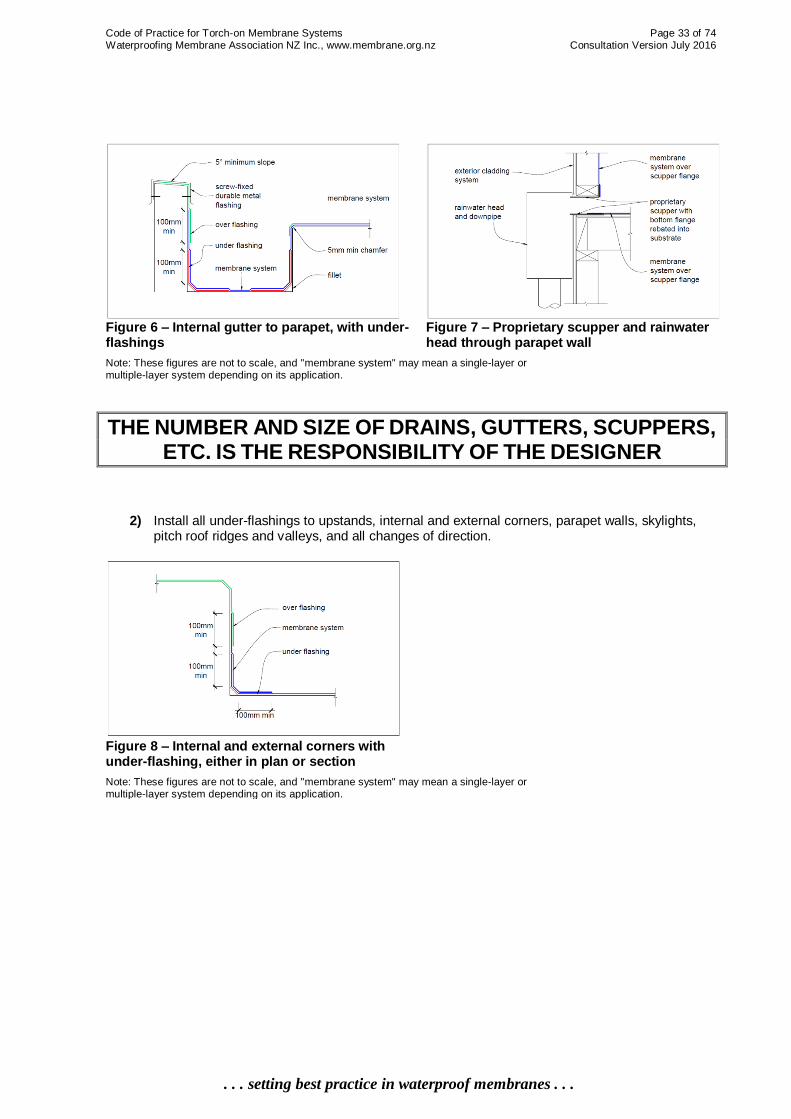
Code of Practice for Torch-on Membrane Systems Page 33 of 74 Waterproofing Membrane Association NZ Inc., www.membrane.org.nz Consultation Version July 2016
. . . setting best practice in waterproof membranes . . .
Figure 6 – Internal gutter to parapet, with under-flashings
Figure 7 – Proprietary scupper and rainwater head through parapet wall
Note: These figures are not to scale, and "membrane system" may mean a single-layer or multiple-layer system depending on its application.
THE NUMBER AND SIZE OF DRAINS, GUTTERS, SCUPPERS, ETC. IS THE RESPONSIBILITY OF THE DESIGNER
2) Install all under-flashings to upstands, internal and external corners, parapet walls, skylights, pitch roof ridges and valleys, and all changes of direction.
Figure 8 – Internal and external corners with under-flashing, either in plan or section
Note: These figures are not to scale, and "membrane system" may mean a single-layer or multiple-layer system depending on its application.

Code of Practice for Torch-on Membrane Systems Page 34 of 74 Waterproofing Membrane Association NZ Inc., www.membrane.org.nz Consultation Version July 2016
. . . setting best practice in waterproof membranes . . .
Figure 9 – Under-flashing of external corner with gusset
Figure 10 – Under-flashing of internal corner
Note: These figures are not to scale, and "membrane system" may mean a single-layer or
multiple-layer system depending on its application.
3) Install torch-on membrane to gutter (if applicable) including stop-ends, into droppers, parapet outlets, overflows, fascias, drip edges, verges, barge boards and all junctions where a double layer is required.
Where a metal drip flashing is incorporated, it must be designed for the purpose, non-rusting (or suitably protected), at least 0.9mm aluminium or 0.55G non-corroding mild steel, and mechanically fastened every 150mm into a recessed channel by screwing into solid timber.
There are many methods of creating a drip edge at the fascia/barge/verge or into a proprietary gutter. The preference is to create this out of the membrane to continue the weatherproof system. Where falls are slight, e.g. decks, install a flashing under the substrate and rout the top to give a radius that the membrane can more easily be shaped over.
Figure 11 – Metal drip edge, rebated and under-flashed
Figure 12 – Verge with under-flashing around shaped timber packer
Note: These figures are not to scale, and "membrane system" may mean a single-layer or multiple-layer system depending on its application.

Code of Practice for Torch-on Membrane Systems Page 35 of 74 Waterproofing Membrane Association NZ Inc., www.membrane.org.nz Consultation Version July 2016
. . . setting best practice in waterproof membranes . . .
Figure 13 – Verge with metal over-flashing and membrane under-flashing
Figure 14 – Verge with metal over-flashing, membrane under-flashing & expressed timber trim
Note: These figures are not to scale, and "membrane system" may mean a single-layer or multiple-layer system depending on its application.
Figure 15 – Welted barge Figure 16 – Welted barge with folded under-
flashing
Note: These figures are not to scale, and "membrane system" may mean a single-layer or multiple-layer system depending on its application.
4) Plan the layout pattern of the full membrane sheets, especially if the design calls for a specific pattern for aesthetic reasons. Ensure that the full-sheet layout is compatible with all junctions of detail work, expansion joints, vents and/or penetrations (ensure that they occur mid-sheet rather than at a lap), plinths, etc.
5) Where it is not possible to run the membrane up and over a parapet or into a chase, a compression plate must be used as a mechanical fixing. Fix the membrane around the roof perimeter, up parapets and/or walls and other susceptible areas as required.
6) Mechanically fix the base layer as required for high wind situations.
For High wind zones (38-44m/s) there must be additional mechanical fixing at all perimeter edges and ridges, on roofs both with and without parapets, with Supplier-nominated fixings at 300mm minimum centres and with fixings extending perpendicular to the perimeter for 0.9m at all laps.
For all Very High or greater wind zones (greater than 44m/s), in accordance with AS/NZS1170.2:2011, the base layer must be mechanically fixed to the substrate with Supplier-nominated fixings, using a fixing pattern stipulated in the building-specific wind load design provided by the Supplier and confirmed by the Designer.

Code of Practice for Torch-on Membrane Systems Page 36 of 74 Waterproofing Membrane Association NZ Inc., www.membrane.org.nz Consultation Version July 2016
. . . setting best practice in waterproof membranes . . .
Figure 17 – Mechanical fixing with termination bar
Figure 18 – Termination into concrete or masonry wall with metal over-flashing
Note: These figures are not to scale, and "membrane system" may mean a single-layer or multiple-layer system depending on its application.
7) Where the membrane is terminated part-way up a wall, flash with a termination bar or into a sealed chase. Use a compatible elastomeric sealant.
8) Unless a ventilated sheet system is required, install the torch-on membrane either by selecting a self-adhesive membrane or by torching down to achieve a full or partial bond as required.
9) Burn off the backing film to the underside of the membrane during the modified bitumen process or before laying the membrane into a liquid bedding compound.
10) Continue all membranes and form up the wall or parapet, with fillets, to the prescribed height.
11) Cap all parapets. Inadequate waterproofing of parapet caps, corners and roof-to-parapet junction upstands provide a series of potential ingress routes where water can seep in and around, and eventually, behind the membrane.
Figure 19 – Typical parapet capping
Note: These figures are not to scale, and "membrane system" may mean a single-layer or
multiple-layer system depending on its application.
12) Turn the membrane down gutter sidewalls.
13) Turn the membrane down and weld to fascias or into the spouting.
14) Under-flash and heat-weld all wall upstands, parapet walls, skylights and all changes of direction.
15) Install bond-breakers over plywood sheet joints and other construction junctions as required.
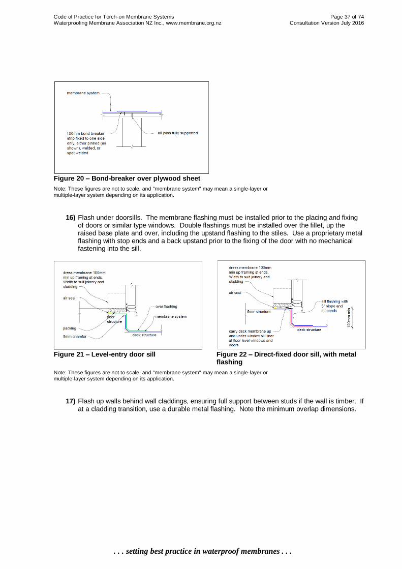
Code of Practice for Torch-on Membrane Systems Page 37 of 74 Waterproofing Membrane Association NZ Inc., www.membrane.org.nz Consultation Version July 2016
. . . setting best practice in waterproof membranes . . .
Figure 20 – Bond-breaker over plywood sheet
Note: These figures are not to scale, and "membrane system" may mean a single-layer or
multiple-layer system depending on its application.
16) Flash under doorsills. The membrane flashing must be installed prior to the placing and fixing of doors or similar type windows. Double flashings must be installed over the fillet, up the raised base plate and over, including the upstand flashing to the stiles. Use a proprietary metal flashing with stop ends and a back upstand prior to the fixing of the door with no mechanical fastening into the sill.
Figure 21 – Level-entry door sill
Figure 22 – Direct-fixed door sill, with metal flashing
Note: These figures are not to scale, and "membrane system" may mean a single-layer or multiple-layer system depending on its application.
17) Flash up walls behind wall claddings, ensuring full support between studs if the wall is timber. If at a cladding transition, use a durable metal flashing. Note the minimum overlap dimensions.

Code of Practice for Torch-on Membrane Systems Page 38 of 74 Waterproofing Membrane Association NZ Inc., www.membrane.org.nz Consultation Version July 2016
. . . setting best practice in waterproof membranes . . .
Figure 23 – Wall/floor/deck junction, with under-flashing
Figure 24 – Wall/deck junction with under-flashing (and full backing support if a timber wall)
Note: These figures are not to scale, and "membrane system" may mean a single-layer or
multiple-layer system depending on its application.
Figure 25 – Termination under and behind existing wall cladding
Note: These figures are not to scale, and "membrane system" may mean a single-layer or multiple-layer system depending on its application.
18) Install venting systems if required to the Designer's specified locations, as per the Supplier's installation procedure.
Figure 26 – Vent for ventilating the membrane Figure 27 – Roof-cavity vent on timber plinth
Note: These figures are not to scale, and "membrane system" may mean a single-layer or multiple-layer system depending on its application.
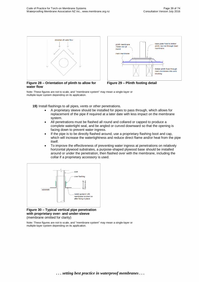
Code of Practice for Torch-on Membrane Systems Page 39 of 74 Waterproofing Membrane Association NZ Inc., www.membrane.org.nz Consultation Version July 2016
. . . setting best practice in waterproof membranes . . .
Figure 28 – Orientation of plinth to allow for water flow
Figure 29 – Plinth footing detail
Note: These figures are not to scale, and "membrane system" may mean a single-layer or
multiple-layer system depending on its application.
19) Install flashings to all pipes, vents or other penetrations.
A proprietary sleeve should be installed for pipes to pass through, which allows for replacement of the pipe if required at a later date with less impact on the membrane system.
All penetrations must be flashed all round and collared or capped to produce a complete watertight seal, and be angled or curved downward so that the opening is facing down to prevent water ingress.
If the pipe is to be directly flashed around, use a proprietary flashing boot and cap, which will increase the watertightness and reduce direct flame and/or heat from the pipe itself.
To improve the effectiveness of preventing water ingress at penetrations on relatively horizontal plywood substrates, a purpose-shaped plywood base should be installed around or under the penetration, then flashed over with the membrane, including the collar if a proprietary accessory is used.
Figure 30 – Typical vertical pipe penetration with proprietary over- and under-sleeve (membrane omitted for clarity)
Note: These figures are not to scale, and "membrane system" may mean a single-layer or multiple-layer system depending on its application.

Code of Practice for Torch-on Membrane Systems Page 40 of 74 Waterproofing Membrane Association NZ Inc., www.membrane.org.nz Consultation Version July 2016
. . . setting best practice in waterproof membranes . . .
Figure 31 – Typical vertical pipe penetration Figure 32 – Typical horizontal pipe penetration
Note: These figures are not to scale, and "membrane system" may mean a single-layer or multiple-layer system depending on its application.
20) Install under-flashing then the roof membrane to a pitch roof ridge, including an over-flashing. Flash to adjacent surfaces including up and under other types of roofing.
Figure 33 – Roof ridge with over-flashing Figure 34 – Roof ridge with under-flashing
Note: These figures are not to scale, and "membrane system" may mean a single-layer or multiple-layer system depending on its application.
Figure 35 – Membrane up wall and under roofing, with solid support
Note: These figures are not to scale, and "membrane system" may mean a single-layer or
multiple-layer system depending on its application.
21) Where expansion joints are detailed, use a proprietary capping. A common cause of premature membrane failure is the lack of properly designed, constructed or flashed construction or expansion joints. It is the responsibility of the Designer to ensure that they are correctly spaced

Code of Practice for Torch-on Membrane Systems Page 41 of 74 Waterproofing Membrane Association NZ Inc., www.membrane.org.nz Consultation Version July 2016
. . . setting best practice in waterproof membranes . . .
and designed. If not detailed, the Applicator must advise the Main Contractor and require the information to be provided.
22) Install saddle- or stop-end flashing where expansion joints terminate against a parapet wall or fascia. These flashings are very site- and construction-specific, so no drawings of this nature have been included in this Code of Practice.
Figure 36 – Metal expansion joint cap, double-sloped, fixed both sides
Figure 37 – Metal expansion joint cap, centre-peaked, fixed both sides
Note: These figures are not to scale, and "membrane system" may mean a single-layer or multiple-layer system depending on its application.
Figure 38 – Metal expansion joint cap, single-sloped, fixed one side
Figure 39 – Flush expansion joint
Note: These figures are not to scale, and "membrane system" may mean a single-layer or multiple-layer system depending on its application.
Figure 40 – Proprietary expansion cap with under-flashing
Note: These figures are not to scale, and "membrane system" may mean a single-layer or multiple-layer system depending on its application.

Code of Practice for Torch-on Membrane Systems Page 42 of 74 Waterproofing Membrane Association NZ Inc., www.membrane.org.nz Consultation Version July 2016
. . . setting best practice in waterproof membranes . . .
23) Complete all upstands, downturns, pipes etc. with an over-flashing.
24) In general, install additional layered flashings to all other junctions (not covered specifically above) such as plinths, air-conditioning unit runners, water-tank feet, balustrade feet or posts – for example by heat forming and welding.
25) After all the detail work has been completed, lay the full membrane sheets. Chalk a line where necessary to position and align the sheets prior to installation to ensure a good layout and correct and even over-lap welds. All adjacent end laps must be staggered.
26) Ensure that all laps are parallel or perpendicular to the slope of the roof so that the flow of water is over the lap and never against or into the exposed lap edge.
27) Overlap all membrane sheets by 100mm minimum at sides, and 150mm at the ends of rolls. All overlaps, including flashings, must be heat-welded to achieve a waterproof joint.
28) Always start at the lowest point of the area to be laid and work up the slope to the highest point.
29) At completion, check all welds for total bond and, if practical, carry out a water test.
30) Clear off all excess materials and plant, leaving the site clean and tidy.
31) If the torch-on membrane is a plain finish, apply the recommended film-build/number of coats of protective coating.
32) Complete the appropriate quality control sheet as the job progresses. Sign off at completion with the Main Contractor and file accordingly.

Code of Practice for Torch-on Membrane Systems Page 43 of 74 Waterproofing Membrane Association NZ Inc., www.membrane.org.nz Consultation Version July 2016
. . . setting best practice in waterproof membranes . . .
5. Site Practice This chapter is primarily written for the Applicator and Main Contractor. It will also assist the Building Consent Authority. It addresses site relations, trade interactions and site safety.
5.0 General This Code of Practice recognises the crucial role of workmanship in the installation of a torch-on membrane system in order that it can perform as required for its full service life. Delivery, storage, handling, quality and condition of materials and control of the installation procedures are also of great importance.
5.1 Administration/Supervision The Applicator is responsible for the quality control and the installation of the torch-on membrane system. The Applicator is to provide the project administration and supervision for the membrane system component of work, plus coordinate all pre- and post-work by other trades with the Main Contractor or Building Owner, to ensure that the work proceeds satisfactorily, provides adequate building protection and minimises disruption to the normal building operations. The Designer, Main Contractor and/or the Building Owner, in consultation with the Applicator, must monitor progress of the membrane work in order to:
Ensure compliance with the approved consent documents that will include the project specifications and drawings
Minimise potential problems
Provide a resolution when and as required A pre-inspection and/or a pre-job meeting of all parties involved with the torch-on membrane system must be held to identify any areas of concern. For a successful installation, it is important to resolve and clarify any issues or project requirements, work programme and interaction with other trades, the project documentation required, product storage, and site health and safety matters.
5.2 Project Commencement Before commencing work, the Applicator must determine that:
All the building consents have been issued, and the specifications and detailed drawings are workable and suitable for the situation at hand.
There is nothing that will compromise the Applicator's required responsibility under this Code of Practice and the Building Code.
No existing conditions at the site prevent the Applicator from performing in a professional and safe manner.
The selected product to be installed is as per the consent documents. If there is any concern, the Applicator must refer the issue back to the Designer. ____________________________________________________________________________________________ Acronyms: BCA = Building Consent Authority; LBP = Licenced Building Practitioner; MSDS = material safety data sheet

Code of Practice for Torch-on Membrane Systems Page 44 of 74 Waterproofing Membrane Association NZ Inc., www.membrane.org.nz Consultation Version July 2016
. . . setting best practice in waterproof membranes . . .
5.3 Acceptable Information The Main Contractor, Building Owner or Applicator's company will provide the following documents to the installation personnel in an accessible location on-site:
Consented project drawings and specifications
Supplier's product technical information sheets
Product material safety data sheets (MSDS)
The current health and safety documents and Working at Heights guidelines
Any other relevant project documents
5.4 Handling of Materials Correct practice for administration, handling and storage of torch-on membrane materials prior to use includes (but is not limited to):
Unload, crane and handle all materials with care.
Check all materials and discard damaged or suspect rolls.
Check that all materials are clearly labelled. Return any unlabelled materials and request new, clearly labelled materials from the Supplier.
Store all membranes on a flat surface, with rolls in the vertical position. Do not store any other materials on top.
Store materials in a dry and protected environment, and do not lift materials onto the roof until immediately before they are required.
Rotate all materials such as adhesives and/or sealants which have a specified shelf life. Store all materials in a cool place prior to use and discard any materials which have passed their use-by date.
When placing materials onto the roof deck, always place them directly above a major structural support until ready for use.
If possible, when lifting materials onto the roof, spread their landing location to reduce point loadings. If this is not possible, spread as soon as practicable after lifting is completed.
Where required, relax the rolls for at least 20 minutes prior to use to eliminate any packaging, transit and/or handling stress.
Protect materials from frost.
Protect materials from sun heat.
Protect membrane already laid during installation.
5.5 Working Conditions Site- and project-specific working conditions are critical to a successful application of a torch-on membrane system. Laying should not take place in frost, rain, snow, high winds, on wet surfaces or in extremes of temperature. The Applicator must check the local existing and forecast weather conditions before commencing, and be prepared at all times to protect any uncompleted work from possible changes in weather conditions. If the work must proceed irrespective of any adverse weather conditions, a temporary roof with sufficient working headroom should be installed over the working area.
5.6 Scheduling of Work As the membrane system will invariably be an integral component of the waterproofing system of the building, all work must be scheduled through the duration of the entire project as well as within any day to minimise the risk of the work not being able to be completed. Be aware of any potential adverse weather patterns, or possible water or moisture ingress from other trades.
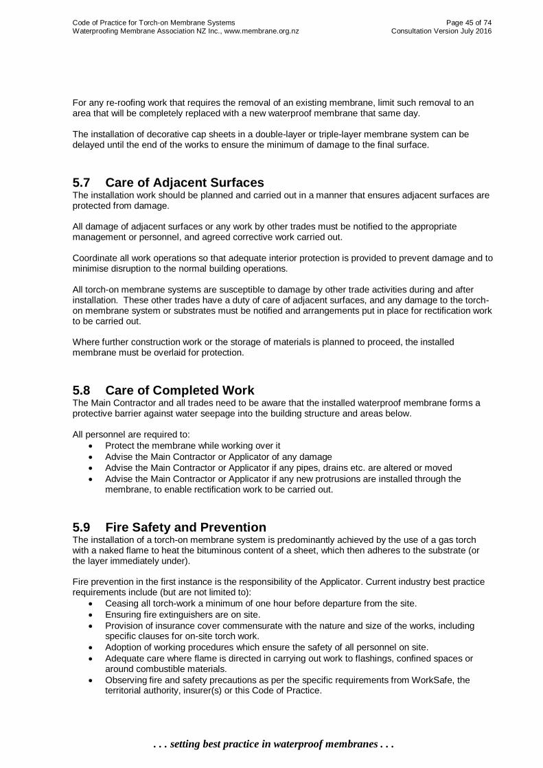
Code of Practice for Torch-on Membrane Systems Page 45 of 74 Waterproofing Membrane Association NZ Inc., www.membrane.org.nz Consultation Version July 2016
. . . setting best practice in waterproof membranes . . .
For any re-roofing work that requires the removal of an existing membrane, limit such removal to an area that will be completely replaced with a new waterproof membrane that same day. The installation of decorative cap sheets in a double-layer or triple-layer membrane system can be delayed until the end of the works to ensure the minimum of damage to the final surface.
5.7 Care of Adjacent Surfaces The installation work should be planned and carried out in a manner that ensures adjacent surfaces are protected from damage. All damage of adjacent surfaces or any work by other trades must be notified to the appropriate management or personnel, and agreed corrective work carried out. Coordinate all work operations so that adequate interior protection is provided to prevent damage and to minimise disruption to the normal building operations. All torch-on membrane systems are susceptible to damage by other trade activities during and after installation. These other trades have a duty of care of adjacent surfaces, and any damage to the torch-on membrane system or substrates must be notified and arrangements put in place for rectification work to be carried out. Where further construction work or the storage of materials is planned to proceed, the installed membrane must be overlaid for protection.
5.8 Care of Completed Work The Main Contractor and all trades need to be aware that the installed waterproof membrane forms a protective barrier against water seepage into the building structure and areas below. All personnel are required to:
Protect the membrane while working over it
Advise the Main Contractor or Applicator of any damage
Advise the Main Contractor or Applicator if any pipes, drains etc. are altered or moved
Advise the Main Contractor or Applicator if any new protrusions are installed through the membrane, to enable rectification work to be carried out.
5.9 Fire Safety and Prevention The installation of a torch-on membrane system is predominantly achieved by the use of a gas torch with a naked flame to heat the bituminous content of a sheet, which then adheres to the substrate (or the layer immediately under). Fire prevention in the first instance is the responsibility of the Applicator. Current industry best practice requirements include (but are not limited to):
Ceasing all torch-work a minimum of one hour before departure from the site.
Ensuring fire extinguishers are on site.
Provision of insurance cover commensurate with the nature and size of the works, including specific clauses for on-site torch work.
Adoption of working procedures which ensure the safety of all personnel on site.
Adequate care where flame is directed in carrying out work to flashings, confined spaces or around combustible materials.
Observing fire and safety precautions as per the specific requirements from WorkSafe, the territorial authority, insurer(s) or this Code of Practice.

Code of Practice for Torch-on Membrane Systems Page 46 of 74 Waterproofing Membrane Association NZ Inc., www.membrane.org.nz Consultation Version July 2016
. . . setting best practice in waterproof membranes . . .
In situations of potential fire concern, cold adhesive bonding of the membrane, thermal self-adhesive membrane or similar type membrane systems must be used.
5.10 Workmanship All work performed by the Applicator or their staff must be carried out by competent, experienced personnel and assistants, equipped with the necessary tools and plant. All installation work must be in accordance with the project specifications and detailed drawings as consented by the BCA. Any departure from these requirements must be approved in writing by the Designer, Main Contractor, Building Owner, BCA and/or the Supplier of the membrane material. Contact the Designer prior to commencement of work to verify whether the proposed departure requires an amendment to the issued building consent. Installation procedures must be in accordance with the Supplier's product data specifications, application manual or any other technical document or instructions provided by the Supplier and approved by the BCA. All work carried out should be in accordance with the relevant sections of this Code of Practice to produce the required standard for a waterproof membrane finish that will meet the provisions of the Building Code.
5.11 Training The long-term performance of the torch-on membrane system is highly dependent on the procedures adopted and standard of workmanship in the preparation, installation and finish of the membrane. Training of all on-site personnel is very important to obtain the required level of competency. The training can be achieved by any of the following, or a recognised alternative:
On-site training and supervision by a qualified and experienced Applicator.
In-house training seminars at the Applicator's premises.
Training seminars provided by the Supplier or membrane Manufacturers.
Attending training courses by recognised and accredited providers. A requirement of the Building Act 2004 is that all tradespeople involved in "critical works" – which in this situation involves all trades to do with the weatherproofing of any building element – are required to be a Licensed Building Practitioner (LBP) or to be supervised by an LBP.
5.12 Health and Safety It is the responsibility of Applicators to be conversant with and to carry out the required safety procedures for their immediate surroundings and work practices. Potential hazards during the installation of torch-on membranes include (but are not limited to):
Injury to the Applicator or other persons on the work site, either directly from the gas torch or from contact with heated bitumen or other materials
Fires from torch-work, including smouldering fires
Falls, as most torch-on membranes are applied to either roofs or decks, which will usually be 2.5m or more above the ground.
Applicators must comply with all applicable and appropriate requirements under the Health and Safety in Employment Act 1992. Refer to WorkSafe New Zealand for more information.

Code of Practice for Torch-on Membrane Systems Page 47 of 74 Waterproofing Membrane Association NZ Inc., www.membrane.org.nz Consultation Version July 2016
. . . setting best practice in waterproof membranes . . .
Required on-site safety practices and procedures include (but are not limited to):
Protective clothing to be worn by Applicators, including a hat and suitable footwear. In particular, heat-resistant gloves must be worn to reduce the risk of heated bitumen coming into contact with skin.
When working with a gas torch, due care to be exercised both by the Applicator and other associated personnel and other persons on the work site whilst this work is being carried out.
Regular checks of all gas equipment to ensure that it is in good working order and safe for use.
Thorough training of all personnel in the proper use and maintenance of this equipment.
Ensuring that the Applicator is trained in fire prevention and the proper extinguishing of fires.
Ensuring that code-compliant fire extinguishing equipment is kept close to the membrane installation area and is in good working order.
Ensuring that first aid equipment is provided on site, and that work personnel are trained in first-aid procedures.
Ensuring that all personnel working at height have appropriate training and experience, including understanding restraint procedures.
Complying with all project-specific site safety requirements. For example, while roof shoes are preferred footwear for installation of torch-on membranes because hard-sole boots or shoes may leave imprint marks, this may be incompatible with project-specific site safety requirements.
5.13 Successful Site Practice The following are suggested guidelines for the Applicator:
Meet with the Main Contractor/project management and other trades prior to commencing installation to ensure that all are aware of the scope of the works, especially where there are preceding or follow-on trades.
Peruse all contract documents to ascertain what is specified and approved.
Provide all relevant technical data-spec sheets or installation instructions to application staff.
Ensure there is a quality-control process in place for signing off acceptance or otherwise of the membrane substrate.
Ensure that the waterproofing membrane system is appropriate for the task.
Ensure that there is adequate supervision of the installation and quality control by project management and the application company.
Protect all waterproofing membranes from damage by other trades.
Ensure that the work programme is appropriate, i.e. the correct sequencing of other trades before and after installation.
Ensure application staff are adequately trained.
Get sign off for the work completed.

Code of Practice for Torch-on Membrane Systems Page 48 of 74 Waterproofing Membrane Association NZ Inc., www.membrane.org.nz Consultation Version July 2016
. . . setting best practice in waterproof membranes . . .
6. Installation This chapter is primarily written for the Applicator and Building Consent Authority. It will also assist the Main Contractor. It addresses the sequencing of installation and correct application methodology.
6.0 General All work must be carried out by an Applicator and installed in accordance with the requirements of the building consent and contract documentation, having regard to the membrane system selected as well as:
Workmanship and application experience
Site conditions and current industry best practice
Selection of membrane and system
Torch-on membrane layout
Fixing, adhesion method and detailing
Site safety
Coordination with the Main Contractor with regard to penetrations and other trades
Site-specific conditions
6.1 Pre-Inspection Before commencing any work on site, a pre-installation meeting must be held to discuss the overall project in general and the specific working conditions. Applicators should make themselves aware of:
Any normal and/or special project conditions or conditions of contract relating to the torch-on membrane system.
The overall project programme and the proposed membrane installation timing within the programme, as coordinated by the Main Contractor.
The name of the person who is responsible for scheduling of work of other trades. Applicators should also satisfy themselves that:
Suitable and sufficient storage is available for materials and plant.
Adequate water, power, lighting and other required facilities are available on site.
Suitable crane equipment is available for the movement of materials from storage to any roof.
Suitable access is provided to the work location.
All site health and safety requirements are addressed in regard to the membrane work.
The membrane will be protected from use by other trades, both while installation work is in progress and after completion. Once the installation is completed, the Main Contractor must assume responsibility for protection of the membrane system.
There are facilities for the daily removal of rubbish, surplus material and plant. _______________________________________________________________________________________________
Acronyms: BCA = Building Consent Authority; CuN = copper nitrate; LOSP = light organic solvent preservative; HVAC = heating ventilation air-conditioning (Engineer)
Code of Practice for Torch-on Membrane Systems Page 49 of 74 Waterproofing Membrane Association NZ Inc., www.membrane.org.nz Consultation Version July 2016
. . . setting best practice in waterproof membranes . . .
6.1.1 Overall Project Pre-Inspection Before commencement of work on site, ensure that the overall building project has sufficiently progressed to be ready for the application of the torch-on membrane system. A pre-inspection and/or a meeting of all parties involved in the roof/deck part of the project must be held to identify any areas of concern. Specifically, obtain confirmation in writing from the Main Contractor that the conditions of contract and building consent documentation relating to the installation of the substrate have been met. Similarly, where possible, obtain confirmation from the BCA or Main Contractor that that the substrate has been constructed and inspected as required by the building consent documentation. 6.1.2 Working Conditions Pre-Inspection The surface to be covered with the torch-on membrane system itself must be acceptable before application commences. There are many potential factors that can reduce the effectiveness of a torch-on membrane system. The Applicator must inspect the substrate and notify the Main Contractor in writing of any such design or construction faults, or damage of the substrate. All fault(s) must be fully rectified before the Applicator commences work in that area. Avoid potential faults and failures by checking the following (listed in no particular order and not limited to):
The roof has sufficient substrate strength to accept the dead load of stacked or stored membrane materials prior to installation.
The substrate surface is dry and the moisture content of the substrate is low enough to commence installation.
The substrate surface is clean and suitable for the torch-on membrane system to be applied.
Adequate provision has been made for local wind-load conditions in the construction details.
Falls, drainage and discharge meet the requirements of the consent documentation.
Expansion joints and their construction and finish meet the requirements of this Code of Practice.
Allowance has been made for all penetrations, fixtures and attachments.
All flashing details are sufficient and meet the requirements of the consent documentation and the Building Code.
All roof openings or protrusions such as pipes, sleeves, ducts, vents and skylights have been constructed in accordance with the consent documentation before application of the torch-on membrane system.
Any ventilation requirements, including roof cavities, have been designed and specified by a suitably qualified Designer, for example an HVAC Engineer.
6.2 Substrate Inspection 6.2.0 General A critical factor in the successful application of a torch-on membrane system, apart from the membrane system itself, is the substrate. This includes the structural support, the surface to which the membrane is fixed and the preparation of that surface. 6.2.1 The Substrate The substrate is the structural element upon which the torch-on membrane system is to be laid. It must be sufficiently designed to withstand point and working loads, and to have sufficient falls, water-discharge and overflow mechanisms for the expected local weather conditions. Refer to Chapter 4.0 (Design).

Code of Practice for Torch-on Membrane Systems Page 50 of 74 Waterproofing Membrane Association NZ Inc., www.membrane.org.nz Consultation Version July 2016
. . . setting best practice in waterproof membranes . . .
The substrate surface preparation is critical to the successful installation and performance of the torch-on membrane system, as the service life of the membrane is dependent on the quality of the adhesion between the substrate surface and the membrane itself. Refer to Section 4.1.4. 6.2.2 The Substrate Surface Torch-on membranes require a surface that is smooth, with no nibs or hollows but with the required falls toward the water outlet system. If the substrate is concrete, it is likely that curing compounds or release agents will interfere with the adhesion of the torch-on membrane system. If a curing compound or release agent has been used, it must be removed. 6.2.3 Surface Preparation When the substrate surface is accepted by the Applicator as suitable to commence work, the substrate surface should be prepared as required by the Supplier of the torch-on membrane system being used. The surface must generally be dry, clean and smooth – i.e. free of any contaminants, concrete splashes or nibs, dust, holes, nails, bolts or any other protrusions not included in the building plans. The substrate must be primed with the Supplier's specified bitumen primer to ensure the satisfactory adhesion of the torch-on membrane system to the substrate. Where there is a delay between priming of the substrate and installation of the membrane, it may be necessary to clean and re-prime the surface prior to proceeding with installation of the membrane. With adhesive-bonded systems, the adhesive is generally self-priming.
6.3 Installation Procedure All projects differ, and the torch-on membrane system components themselves each have specific requirements. Thus, the required installation procedure could differ for each project. The installation of torch-on membranes can be carried out by a range of methods:
By the application of heat, usually a portable gas torch, to the underside of the membrane sheet as it is rolled out. This softens the bitumen, which then bonds to the substrate or the membrane layer beneath.
By the application of a thixotropic liquid bitumen bonding compound to the substrate, then laying the membrane sheet onto it.
By the use of a "peel and stick" membrane which already has adhesive on the sheet. At installation, the protective layer is removed and the membrane laid on the substrate. Some thermal-type membranes require heat to be applied over the top for full bonding.
By the application of a mechanically fastened base sheet, to which the cap sheet is subsequently torch-applied.
The material set out in this section is not intended to be an installation manual, but illustrates generic installation principles based on current industry best practice. For example, the phrase "membrane system" where used may be a single- or a multiple-layered system. Some figures may contain several installation principles, and for some principles, alternative methods are shown. Some figures may be similar to another but show an alternative flashing method e.g. an over-flashing rather than an under-flashing. The only dimensions shown are those that are critical to the satisfactory installation of the torch-on membrane system or to meet the requirements of the Building Code. Refer to Figures 2-40.

Code of Practice for Torch-on Membrane Systems Page 51 of 74 Waterproofing Membrane Association NZ Inc., www.membrane.org.nz Consultation Version July 2016
. . . setting best practice in waterproof membranes . . .
Building consent documentation and/or Supplier's details always take precedence over generic construction figures. Final construction design and details are the responsibility of the Designer. Applicators must adhere to the consented construction drawings, the Supplier's written installation instructions and Supplier-specified procedures for the selected membrane system. In general:
All flashings and upstand dimensions shall follow the figures in this Code of Practice.
All fillets to internal corners are 20 x 20mm minimum, and timber fillets are treated to H3.2 minimum. Proprietary bitumen fillets can also be installed.
All external corners are chamfered or arrised 5mm minimum.
Where a multiple-layered membrane system is specified: o The laps of the cap sheet must be offset to the laps of the base or underlying sheet(s). o The upper sheets shall be torched on so that they are fully bonded to the immediate
under-layer.
All flashings and sheet edges with a mineral finish will require preparation to ensure welds are bitumen-to-bitumen unless a cold adhesive compound is used.
Matching granules of the mineral membrane may be broadcast into the heated bitumen bleed seam to improve the finished appearance.
Membrane roofs greater than 40m2 on a plywood substrate may require a bond-breaker over
construction/expansion joints. The bond-breaker must be of a pliable material of sufficient dimension to allow the membrane to accommodate structural movement. Location of the construction/expansion junctions is the responsibility of the Designer.
LOSP- or CuN-treated plywood must not be used as these will cause membrane adhesion problems.
Good heat control throughout the whole process is essential to a good, watertight installation, with sufficient and even heat applied so that bitumen starts to flow. Excessive heat will damage the integrity of the membrane, while poor heat control will result in unsatisfactory bonding to the substrate or immediate layer below, and suspect laps or flashing welds with the potential for leaks.
6.3.1 Installation Steps A typical torch-on membrane system may include some or all of the following installation steps. They are listed in an approximate order of work; however, a specific project may require or the Applicator may choose to do certain tasks in a different order. For all projects:
Plan the entire work programme before commencement.
Perform all detail work (gutters, edges, penetrations, etc.) before full sheet application. Possible installation steps are as follows:
1) Install all droppers, parapet outlets, scuppers, sumps, overflows etc. in substrate recesses if practical, and bed-in to an under-flashing membrane. Use proprietary components where possible with stainless steel or other durable fixings.
The membrane must be flashed down into the drainage outlet, and heat-welded to the sides to prevent water moisture from tracking under the membrane and back into the structure.
In general, drainage from the membrane surface should be via gutters, channels or scuppers into rainwater heads and droppers. Ensure that they are positioned at the lowest point to give effective drainage.
2) Install all under-flashings to upstands, internal and external corners, parapet walls, skylights,
pitch roof ridges and valleys, and all changes of direction.

Code of Practice for Torch-on Membrane Systems Page 52 of 74 Waterproofing Membrane Association NZ Inc., www.membrane.org.nz Consultation Version July 2016
. . . setting best practice in waterproof membranes . . .
3) Install torch-on membrane to gutter (if applicable) including stop-ends, into droppers, parapet
outlets, overflows, fascias, drip edges, verges, barge boards and all junctions where a double layer is required.
Where a metal drip flashing is incorporated, it must be designed for the purpose, non-rusting (or suitably protected), at least 0.9mm aluminium or 0.55G non-corroding mild steel, and mechanically fastened every 150mm into a recessed channel by screwing into solid timber.
There are many methods of creating a drip edge at the fascia/barge/verge or into a proprietary gutter. The preference is to create this out of the membrane to continue the weatherproof system. Where falls are slight, e.g. decks, install a flashing under the substrate and rout the top to give a radius that the membrane can more easily be shaped over.
4) Plan the layout pattern of the full membrane sheets. This is particularly important for the cap
sheet in a multiple-layered system, or if the design calls for a specific pattern for aesthetic reasons.
Ensure that the full-sheet layout is compatible with all junctions of detail work, expansion joints, vents and/or penetrations (ensure that they occur mid-sheet rather than at a lap), plinths, etc.
Where a multiple-layered membrane system is specified, the laps of the cap sheet must be offset to the laps of the base or underlying sheet(s).
5) Install bond-breakers over plywood sheet joints and other construction junctions as required.
6) After all the detail work has been completed, lay the full membrane sheets. Chalk a line where
necessary to position and align the sheets prior to installation to ensure a good layout and correct and even over-lap welds. All adjacent end laps must be staggered.
7) Always start at the lowest point of the area to be laid and work up the slope to the highest point.
8) Unless a ventilated sheet system is required, install the torch-on membrane either by selecting a self-adhesive membrane or by torching down to achieve a full or partial bond as required.
9) Burn off the backing film to the underside of the membrane during the torch-on process or before laying the membrane into a liquid bedding compound.
10) Ensure that all laps are parallel or perpendicular to the slope of the roof so that the flow of water is over the lap and never against or into the exposed lap edge.
11) Overlap all membrane sheets by 100mm minimum at sides, and 150mm at the ends of rolls. All overlaps, including flashings, must be heat-welded to achieve a waterproof joint.
12) Mechanically fix the base layer as required for high wind situations.
For High wind zones (38-44m/s) there must be additional mechanical fixing at all perimeter edges and ridges, on roofs both with and without parapets, with Supplier-nominated fixings at 300mm minimum centres and with fixings extending perpendicular to the perimeter for 0.9m at all laps.
For all Very High or greater wind zones (greater than 44m/s), in accordance with AS/NZS1170.2:2011, the base layer must be mechanically fixed to the substrate with Supplier-nominated fixings, using a fixing pattern stipulated in the building-specific wind load design provided by the Supplier and confirmed by the Designer.
13) Continue all membranes up walls or parapets, with fillets, to the prescribed height. Where the membrane is terminated part-way up a wall, flash with a termination bar or into a sealed chase. Use a compatible elastomeric sealant.

Code of Practice for Torch-on Membrane Systems Page 53 of 74 Waterproofing Membrane Association NZ Inc., www.membrane.org.nz Consultation Version July 2016
. . . setting best practice in waterproof membranes . . .
14) Where it is not possible to run the membrane up and over a parapet or into a chase, a compression plate must be used as a mechanical fixing.
15) Turn the membrane down gutter sidewalls.
16) Turn the membrane down and weld to fascias or into the spouting.
17) Flash under doorsills. The membrane flashing must be installed prior to the placing and fixing of doors or similar type windows. Double flashings must be installed over the fillet, up the raised base plate and over, including the upstand flashing to the stiles. It is also recommended that a proprietary metal flashing with stop ends and a back upstand be installed prior to the fixing of the door with no mechanical fastening into the sill.
18) Flash up walls behind wall claddings, ensuring full support between studs if the wall is timber. If at a cladding transition, use a durable metal flashing. Note the minimum overlap dimensions.
19) Install venting systems if required to the Designer's specified locations, as per the Supplier's installation procedure.
20) Install flashings to all pipes, vents or other penetrations.
A proprietary sleeve should be installed for pipes to pass through, which allows for replacement of the pipe if required at a later date with less impact on the membrane system.
All penetrations must be flashed all round and collared or capped to produce a complete watertight seal, and be angled or curved downward so that the opening is facing down to prevent water ingress.
If the pipe is to be directly flashed around, use a proprietary flashing boot and cap, which will increase the watertightness and reduce direct flame and/or heat from the pipe itself.
To improve the effectiveness of preventing water ingress at penetrations on relatively horizontal plywood substrates, a purpose-shaped plywood base should be installed around or under the penetration, then flashed over with the membrane, including the collar if a proprietary accessory is used.
21) Where expansion joints are detailed, use a proprietary capping. A common cause of premature membrane failure is the lack of properly designed, constructed or flashed construction or expansion joints. These are very site- and construction-specific and it is the responsibility of the Designer to ensure that they are correctly spaced and designed. If not detailed, the Applicator must advise the Main Contractor and require the information to be provided.
22) Complete all upstands, downturns, pipes etc. with an over-flashing.
23) If a multiple-layered system, torch on the upper sheets so that they are fully bonded to the immediate under-layer.
24) In general, install additional layered flashings to all other junctions (not covered specifically above) such as plinths, air-conditioning unit runners, water-tank feet, balustrade feet or posts – for example by heat forming and welding.
25) Cap all parapets. Inadequate waterproofing of parapet caps, corners and roof-to-parapet junction upstands provide a series of potential ingress routes where water can seep in and around, and eventually, behind the membrane.
26) At completion, check all welds for total bond and, if practical, carry out a water test.
27) Clear off all excess materials and plant, leaving the site clean and tidy.

Code of Practice for Torch-on Membrane Systems Page 54 of 74 Waterproofing Membrane Association NZ Inc., www.membrane.org.nz Consultation Version July 2016
. . . setting best practice in waterproof membranes . . .
28) If the torch-on membrane is a plain finish, apply the recommended film-build/number of coats of protective coating.
29) Complete the appropriate quality control sheet as the job progresses. Sign off at completion with the Main Contractor and file accordingly.
6.3.2 Daily Project Pre-Check Notwithstanding the overall project and substrate checks that have been made, Applicators should take the following steps immediately prior to commencing work each day:
Check the weather forecast to ensure the weather conditions are and will remain appropriate for application of the torch-on membrane system. All work should be carried out in fine weather to avoid trapping in moisture.
Check that all substrate surfaces in the immediate working area are clean and dry.
Ensure that other trades are aware that you will be commencing work, and that there are no issues arising with coordination of work with other trades.
6.3.3 Daily Project Cleanup Tasks The Applicator must clear all installation debris, cut-offs, scraps and protective wrappings from the work site on a daily basis.
6.4 Post-Installation Work During the course of regular in-service maintenance, the whole roof or deck should be systematically checked and a note made of any items requiring attention. The following is a recommended minimum checklist:
Surface protection – Check that the surface protection layer is in place and complete. Note any wind scour, displacement of ballast, cracked or damaged pavers.
Flashings – Check that flashings are intact and fully secured with pointing or sealing complete.
Upstands – Check that upstands are intact, fully adhered and adequately protected. Note any areas of distortion or stress and any blistering.
Penetrations – Inspect the torch-on membrane around each penetration. Ensure that flashings and upstands are intact.
Edge trims – Check for signs of movement, displacement or stress, particularly at the joint between torch-on membrane roofing and metal trims.
General area – Examine the whole of the general roof or deck area and note any areas of stress, any signs of blistering, or any indications that the membrane is detached from the substrate. Record the type and extent of any defects.
Lap joints – Check for integrity.
Drainage – Inspect all gutters and rainwater outlets and discharge points. Ensure they are clean and that water discharge from the roof is uninterrupted. Carefully examine the junction between the torch-on membrane roofing and rainwater outlets. Note any apparent defects or signs of silting or ponding.
Inside the building – Check inside the building for any staining or indication of damp penetration or condensation, which could be related to the roofing.
Completed torch-on membrane roofs or decks must not be used for storage of materials unless fully protected by rigid durable sheet material, and no work by other trades may be carried out on or over an unprotected torch-on membrane.
Code of Practice for Torch-on Membrane Systems Page 55 of 74 Waterproofing Membrane Association NZ Inc., www.membrane.org.nz Consultation Version July 2016
. . . setting best practice in waterproof membranes . . .
6.5 Flood Testing Flood testing shall be carried out by either:
a) Temporarily blocking the drainage outlets, flooding the roof or deck with water and leaving in place for at least 24 hours. For large roofs, sand bagging may be required to prevent the spread of water or to contain it to allow a maximum depth of 50mm of applied water across the area being tested, as water to greater depths may stress the roof structure.
b) Continuous water flow for at least 24 hours across the roof. Inspections are then carried out, looking for any leakages, stains or damage to the substrate or building components beneath and/or alongside. Should leakage be detected, the installer must be advised and requested to return to site to remediate the leaking area. The flood test must then be repeated until no leaks are detected. The Specifier may request alternative testing methods. These must not interfere with the integrity of either the substrate, the substrate surface or the complete torch-on membrane system, nor be detrimental to the performance of the membrane system in any way. Refer to the Supplier for information to support the design.
6.6 Post-Installation Penetrations A major reason for leaks in a torch-on membrane system is penetration of the membrane by other following trades during the construction project or at a later date. Regardless of the size of the penetration (e.g. a skylight compared to a TV cable), the most critical aspects are the skills of the tradesperson, how the penetration is detailed and how the work is carried out. Such post-installation penetrations will usually be minor and often not consented. However, this does not reduce the requirement that such work be carried out to the same standard as the original installation. It will require more attention to detail for a successful integration of the new work with the existing. It is highly recommended that the original Applicator, Designer and/or Supplier are consulted to ensure that waterproofing integrity and the consequent warranties are maintained.

Code of Practice for Torch-on Membrane Systems Page 56 of 74 Waterproofing Membrane Association NZ Inc., www.membrane.org.nz Consultation Version July 2016
. . . setting best practice in waterproof membranes . . .
7. Maintenance (or "through-life care") This chapter is primarily written for the Building Owner. It will also assist the Designer and Applicator. It addresses the care and maintenance of torch-on membrane systems after installation, and of over-surfacing materials where they are required.
7.0 General A torch-on membrane system which has been designed and installed in accordance with this Code of Practice should give trouble-free service for many years, provided it is properly maintained. Similarly, Building Owners would expect their roofing system to remain durable. In New Zealand, the Building Code requires that roof claddings, with normal maintenance, are waterproof for at least 15 years. The serviceable life of torch-on membrane roofing systems depends on:
The underlying building design and construction
The stability of the substrate
The type, grade and formulation of the torch-on membrane system installed
The thickness of the finished application
The standard of installation by the Applicator
The level of UV exposure and/or protection
Activities that occur on and over the torch-on membrane
Attention to maintenance requirements Preventive maintenance by regular inspection checks is highly recommended, rather than waiting for either catastrophic failure to occur or systematic failure to become evident. The frequency of inspections will depend upon local conditions, use of or activities on the membrane, close proximity of trees, degree of atmospheric pollution, etc. It is recommended that in the writing of the contract, the Designer, Supplier and/or Applicator notify the Building Owner of liability conditions and maintenance requirements of the torch-on membrane system. All references to the Building Owner and their responsibilities also apply to their Agents or contracted parties. Prudent risk management of the building as a whole suggests that regular inspection and maintenance of the torch-on membrane is an important part of avoiding future problems. Further, to ensure the best and regular care, such work should form part of any maintenance contract. Ideally, the regular inspection should be carried out by the Supplier and an approved Applicator.
7.1 Defects Liability Post practical completion defects liability requirements are covered in the original contract documents for the construction of the building, the re-surfacing tender documents or any other written commercial obligations. The obligations extend to the end of the Defects Liability Period, the length of which will have been stated in the contract. The Building Owner must read these documents and be aware of the maintenance defects liabilities obligations and period. _______________________________________________________________________________________________ Acronyms: CCA = copper chrome arsenate

Code of Practice for Torch-on Membrane Systems Page 57 of 74 Waterproofing Membrane Association NZ Inc., www.membrane.org.nz Consultation Version July 2016
. . . setting best practice in waterproof membranes . . .
7.2 Preventive Maintenance The long-term performance of the torch-on membrane system installed on any building is reliant on the Building Owner implementing a good housekeeping or preventive maintenance programme. The roof should be inspected periodically to determine its condition and any areas of concern identified, including noting moisture ingress to the interior. Any problems must be reported to the membrane Applicator or the Supplier, so that prompt remedial work can be carried out. The following are some of the requirements. Others are covered under various headings throughout this Code of Practice, or in an inspection checklist provided by the Main Contractor. 7.2.1 Checking Ensure there is no damage to the membrane or any potential water entry created by checking during and after work by other trades on the building (for example, the installation of a TV aerial or air conditioning unit). Call on the services of the membrane Applicator if required. 7.2.2 Clearing Check gutters, sumps, drains, overflows and corners for accumulated rubbish, leaves, branches, silt and plant growth and remove anything that can cause blockage. 7.2.3 Cleaning Wash down the membrane surface yearly at low pressure – not only to clean the surface but also to enable thorough inspection of the roof membrane. 7.2.4 Treating Should any moss, mould or lichen infestation appear, treat with a solution as recommended by membrane Supplier and wash down at low pressure. 7.2.5 Inspecting Thoroughly inspect the complete membrane surface, including gutters, sumps, drains, flashings, penetrations and upstands at least yearly. Note any areas of concern and carry out rectification work. 7.2.6 Re-coating To ensure a coated torch-on membrane performs as required, clean, prepare and re-coat every 5-7 years or at signs that the existing coating is deteriorating. To extend the performance of the membrane beyond 15 years, the Applicator should be engaged to check, carry out any repairs that may be required and re-coat.
7.3 Remedial Work The Building Owner must notify the Applicator if they become aware of:
Faults found in the membrane
Mechanical damage caused to the membrane.
Subsequent installation work, such as TV aerial, vents, air conditioning unit, etc.
Building alterations or extensions Prompt notification is vital to not only rectify a problem, but to reduce any subsequent water ingress problems.

Code of Practice for Torch-on Membrane Systems Page 58 of 74 Waterproofing Membrane Association NZ Inc., www.membrane.org.nz Consultation Version July 2016
. . . setting best practice in waterproof membranes . . .
7.4 Maintenance Servicing During the course of regular maintenance inspections, the complete roof surface should be systematically checked and any areas requiring attention should be noted. The following is a suggested minimum checklist:
1. General surface – Examine the whole of the general roof area and note any areas of stress, bubbling or blistering, de-lamination from the substrate or within the torch-on membrane system and note the extent and type of defects.
□ 2. Surface condition – Check for accumulated rubbish, silt, leaves, branches and
plant growth, including moss, mould or lichen infestation and the overall condition of the membrane.
□ 3. Overlap welds – Check all overlap welds in the membrane and flashing to ensure
they are fully bonded to the membrane, watertight and functioning as required. □
4. Surface protection – Check that the surface protection layer is in satisfactory condition, i.e. no bare patches of mineral chip or peeling and badly oxidising paint film.
□
5. Flashings – Check all flashings are intact, fully adhered, not ruptured and functioning as required. Note any bad rippling, distortion or stress areas. □
6. Upstands – Check all upstands are intact, fully adhered, adequately protected and functioning as required. Note any areas of distortion or stress. □
7. Penetrations – Inspect the membrane around each penetration to ensure that the flashings are intact, not ruptured, adhering and performing as required. □
8. Edge trim – Check for suspect movement or stress areas, ruptures, de-lamination or displacement at junction places or adjacent surfaces. □
9. Abutting construction – Check parapet wall and other adjacent structures' flashing and/or linings for damage, rippling, distortion or areas of distress and cracking. □
10. Expansion joints – Check movement or expansion joint upstands, flashing or capping to ensure they are functioning as required. □
11. Roof fixtures – Check all roof fixtures and fittings, flashings, collars etc. are sound, not loose or suspect. □
12. Substrate – Check for depressions and ponding created by deflection in substrate and investigate the cause. □
13. Drainage – Check all gutters, sumps, outlets and rainwater discharge points to ensure they are clear of rubbish and clean. Inspect all welds and flashings and note any rippling, distortion or stress areas.
□
14. Sealants – Inspect all sealants to ensure they are not faulty and are performing as required. Note any areas of concern. □
15. Inside building – Check the interior of the building for any staining or dampness signs that would indicate moisture ingress or condensation. □
It is recommended that a contract be entered into between the Building Owner and the Applicator to carry out regular inspections of the installation in line with the above and report back to the Building Owner so that defects identified can be remediated promptly. This will continue the chain of responsibility and ensure that any warranties offered by the Applicator are not invalidated.

Code of Practice for Torch-on Membrane Systems Page 59 of 74 Waterproofing Membrane Association NZ Inc., www.membrane.org.nz Consultation Version July 2016
. . . setting best practice in waterproof membranes . . .
7.5 Repair Procedures Repairs should only be carried out after the type and extent of any defects have been noted and their underlying cause identified. The intention of repair work should be to restore the roofing to its original condition and ensure its continuing performance. All repairs should therefore be carried out using materials, accessories and standards of workmanship etc. compatible with the original installation. The Applicator carrying out any repair, re-coating or re-surfacing of the torch-on membrane must do so in a manner that causes the least inconvenience to the occupiers or normal operations within the building.
7.6 Re-coating Re-coating of any torch-on membrane system must only be carried out with compatible materials; thus the original Designer, Supplier and Applicator should be consulted before any work is carried out. The re-coating work will require the following steps:
1. Remove all accumulated rubbish or plant growth. 2. Apply a recommended moss, mould and lichen treatment solution and leave for the required
duration. 3. Scrub, wash or water blast clean at low pressure to a sound surface. 4. Repair the membrane installation as required. 5. Prime/touch up any areas of damaged coating. 6. Apply required number of coats of protective coating.
7.7 Re-surfacing Once the original torch-on membrane has reached its economic lifespan and repairs and re-coating are no longer an option, a decision must be made to either remove and replace the membrane, or overlay with a compatible material. 7.7.1 Removal and Replacement When an existing roof membrane system has deteriorated beyond repair or the substrate is suspect and it is not advisable to overlay it, then the existing membrane must be removed and a new torch-on membrane system installed. Removing an existing roof membrane exposes the building to potential inclement weather and therefore must only go ahead if the long-term forecast indicates a sufficient period of fine weather to complete the project. Alternatively, install a temporary weatherproof protection system over the working area as required. Depending on the size of the project, it is recommended that the removal of the existing membrane and installation of the new membrane be completed in stages, sealing all leading or exposed edges at the end of each day. Avoid removing large sections that cannot be protected from the weather or re-surfaced that day. The work should be planned to cause the least possible damage from water or other building material ingress or disruption to the building occupiers, operations or activities. If the existing membrane is being removed, the following work procedure is required:
1. Remove all existing membranes, including flashings, back to the substrate. 2. Check, repair and prepare the substrate for re-surfacing. Any ponding areas are to be made
flush before laying any new membrane. 3. If the substrate is plywood, check and remove any faulty plywood and/or supporting timber.
Replace with treated timber and CCA-treated plywood (H3.2 grade) – refer to Section 4.1.4.1. 4. Remove and replace all existing metal flashings that are faulty.

Code of Practice for Torch-on Membrane Systems Page 60 of 74 Waterproofing Membrane Association NZ Inc., www.membrane.org.nz Consultation Version July 2016
. . . setting best practice in waterproof membranes . . .
5. Check the falls and recreate where required to ensure that surface water will drain to the outlets.
6. In general, thoroughly prepare the surface, then prime with an approved bitumen primer before installing the new membrane.
7. Use Figure 1 and Table 6 to select the correct torch-on membrane system for the project, giving consideration to venting the substrate.
8. Install as per Section 6.3. 7.7.2 Overlaying Overlaying or re-surfacing the existing membrane with a compatible torch-on membrane system requires suitable preparation. Consult the membrane Supplier or an Applicator. Suspect trapped moisture in the original membrane or substrate will require venting, either by the installation of air-vents, a vent sheet in a double-layer system, or both. A sound, well-adhered existing membrane may be re-surfaced with a suitable single-layer torch-on membrane. If the existing membrane is to remain in place, thorough surface cleaning and preparation is vital to ensure good adhesion and long-term performance of the new membrane. The following work procedure is required:
1. Apply a suitable moss, mould and lichen solution to the complete membrane surface and leave for the prescribed period.
2. Water-blast clean and leave to dry. 3. Repair the existing membrane to render it weathertight. 4. Heat and remove any degraded material to restore a sound surface. 5. Heat and remove the existing mineral finish, or heat to bring up the bitumen and press mineral
down into the membrane. Alternately, overlay with a bitumen compound. Either system must provide a suitable surface for good adhesion of the new membrane.
6. Install a vent sheet, air-vents or both if required. 7. Install cap sheet of the selected finish. 8. Coat with a protective coating if required.

Code of Practice for Torch-on Membrane Systems Page 61 of 74 Waterproofing Membrane Association NZ Inc., www.membrane.org.nz Consultation Version July 2016
. . . setting best practice in waterproof membranes . . .
8. Definitions The following definitions apply in relation to this Code of Practice only, as they may have alternative meanings elsewhere in the industry. Some of the terms below may not appear in this document but are included as they are commonly used in this industry.
Term Definition in Torch-on
Absorption As a measure: The relationship of the weight of the water absorbed by a material specimen
subjected to prescribed immersion procedure, to the weight of the dry specimen, expressed in percent.
As a material property: The ability of a material to accept (absorb) quantities of liquid, such as water, within itself.
Acceptable Solution Acceptable Solutions and Verification Methods are for use in establishing compliance with the
New Zealand Building Code. They are prepared by MBIE in accordance with Section 22 of the Building Act 2004.
A person who complies with an Acceptable Solution or Verification Method will be treated as having complied with the provisions of the Building Code. However, using an Acceptable Solution or Verification Method is only one method of complying with the Building Code. There may be alternative ways to comply.
See also: Alternative Solution.
Acoustic layer A sound insulating material.
Acrylic latex Water-based dispersion resins made by polymerisation of acrylic monomers, such as ethyl acrylate and methacrylate.
Adhesion The strength of bonding of two materials. Failure will result in a fracture at the interface between the two materials.
See also: Cohesion.
Adhesive A material that holds two other materials together by surface attachment or bonding.
Adhesive-bonded A method for bedding and adhering bituminous membranes onto substrates where an adhesive compound is applied to the substrate and the membrane is then embedded into the adhesive.
See also: Cold lay, Cold laid.
Adhesive failure The failure of two materials to remain adhered together. Failure will result in a fracture at the interface between the two materials.
See also: Cohesive failure.
Aging The physical effects on material that are exposed to an environment for a period of time.
Alligatoring Random minor cracking of the surface bitumen of the torch-on membrane.
Alternative Solution A design solution that differs totally or partially from Acceptable Solutions or Verification Methods as published by MBIE, yet complies with the performance requirements of the
Building Code. These are "stand-alone" solutions put forward and substantiated by the building consent applicant and considered and approved on their individual merits by a Building Consent Authority.
See also: Acceptable Solution.
Ambient temperature The room temperature or the temperature of the surroundings (fluid or air).
Angle fillet See: Fillet.
APAO Amorphous polyalphaolefin.
APP-modified Bitumen modified by the addition of atactic polypropylene during the sheet manufacturing process.
Application rate The quantity (mass, volume or thickness) of material applied per unit area.
Applicator (person) An Applicator is a site worker employed by the Applicator company.
The Applicator must work within recommended trade practices and undergo sufficient training to ensure that the product is installed as required by the Supplier.
Torch-on membrane systems fall within MBIE's Licensed Building Practitioner scheme and are Restricted Building Work.
See also: Restricted Building Work.

Code of Practice for Torch-on Membrane Systems Page 62 of 74 Waterproofing Membrane Association NZ Inc., www.membrane.org.nz Consultation Version July 2016
. . . setting best practice in waterproof membranes . . .
Applicator (company) Any company approved by the Supplier to install its product.
AS/NZS A joint Australia and New Zealand Standard.
Atactic polypropylene See: APP-modified.
B2/AS1 B2 refers to Clause B2 "Durability" of the Building Code, and "B2/AS1" is an Acceptable Solution for Clause B2. Buildings designed and built to B2/AS1 are deemed by MBIE to comply with the performance requirements of Clause B2.
Backer rod A closed-cell foam rod inserted in a joint to be sealed, to provide non-adhesion to the substrate and to regulate the depth of sealant.
Ballast An anchoring material laid over the torch-on membrane to add weight to assist in holding the membrane in place, particularly to resist uplift by wind. Usually gravel-like material, aggregate or loose-laid concrete pavers. Also provides UV and physical protection to the torch-on membrane, improved appearance and drainage.
Base layer, Base sheet The under- or first layer (sheet) of a multi-layered (sheet) torch-on membrane system with overlap joints welded.
BCA See: Building Consent Authority.
Bio-resistance Resistance to degradation by biological attack.
Bituminous emulsion A stabilised suspension of bituminous material in water.
Blister An enclosed pocket of vaporised water and/or solvent trapped between substrate and the torch-on membrane or between impermeable layers of the torch-on membrane.
Blocking A specifically-placed framing element between structural members to support finish fittings or sheet joins.
Bond-breaker A material used to prevent adhesion between two elements to allow substrate structural movement and reduce stress on the torch-on membrane layer.
Bond strength The force per unit area necessary to rupture a bond.
Bonding Adhesion of two elements.
See also: Adhesion.
Bonding agent A chemical substance applied to a suitable substrate to enhance a bond between it and a subsequent layer.
Boot A pre-formed shaped material to seal around a penetration.
Bridging When the membrane is unsupported at a juncture.
Buckle, Buckling An upward elongated tenting displacement (rippling) of the torch-on membrane due to movement in the substrate or structure.
(NZ) Building Code The First Schedule to the Building Regulations 1992 that sets national, mandatory standards for building work. All building work in New Zealand must comply with the Building Code. The Building Code is performance-based and specifies how a building and its components must perform, as opposed to how the building must be designed and constructed.
Building Consent Authority (BCA) A Building Consent Authority is a territorial authority, regional authority or private body that has been registered by MBIE after having been assessed and accredited by the Building Consent Accreditation Body. BCAs issue building consents, undertake inspections during
construction and issue Code Compliance Certificates, notices to fix and compliance schedules.
Building-specific Specific design which relates solely to an individual structure having regard to its dimensions, shape, location and materials of construction.
Cap sheet The top or finish layer to a torch-on membrane system.
Cavity ventilation A ventilation system that allows the venting of air or moisture from the space between the substrate of a deck or a roof and the ceiling below.
See also: Substrate Ventilation.
CCA Copper chrome arsenate.
CCC See: Code Compliance Certificate.
Chalking The degradation or oxidisation of the bitumen or coating surface.
Code Compliance Certificate (CCC)
A certificate issued by a Building Consent Authority under Section 95 of the Building Act 2004 at the completion of building work, confirming that the building work complies with the approved building consent.
This can also be called a Consent Completion Certificate.
Cohesion The strength within a material to stay as a whole. Failure will result in a fracture within the body of the material.
See also: Adhesion.

Code of Practice for Torch-on Membrane Systems Page 63 of 74 Waterproofing Membrane Association NZ Inc., www.membrane.org.nz Consultation Version July 2016
. . . setting best practice in waterproof membranes . . .
Cohesive failure The failure of a material to remain as a whole. Failure will result in a fracture within the body of the material.
See also: Adhesive failure.
Cohesive strength The internal strength of a material to remain as a whole.
Cold lay, Cold laid Where a membrane is applied to a surface without being torched-on.
This could be with the use of a self-adhesive membrane or a liquid-bonding compound. Also used in situations where heat or naked flames may be dangerous, e.g. due to proximity to flammable materials.
See also: Adhesive-bonded.
Cold roof Where there is a cavity between the roof structure and ceiling, the principal thermal insulation is placed at or immediately above the ceiling so that the roof covering and structure are at a temperature closer to that of the exterior of the building.
See also: Insulated roof, Inverted roof.
Compliance document See: Acceptable Solution.
Composite modified Two or more bituminous components with reinforcement manufactured to create one single torch-on membrane layer.
Compression bar See: Termination bar.
Concrete curing agent A material applied to concrete to retard the rapid evaporation of moisture to allow the concrete to hydrate more efficiently.
Condensation (on a surface) The conversion of water vapour or other gas to liquid state as the temperature drops or atmospheric pressure rises.
Consent Completion Certificate (CCC)
A consent completion certificate is a formal statement issued by a Building Consent Authority at completion of building work that the building work complies with the building consent.
This can also be called a Code Compliance Certificate.
Contract maintenance See: Maintenance.
Copolymerisation A chemical reaction that results in the bonding of two or more dissimilar monomers to produce large, long-chain molecules, which are copolymers.
Cove, Coving See: Fillet.
Coverage, Coverage rate The surface area covered by a specific quantity of a particular material.
Crack A separation or fracture caused by induced stress, dimensional instability or substrate movement.
Creep The deformation of the bituminous torch-on membrane caused by the movement of the torch-on membrane, due to lack of bonding, thermal stress or loading.
Cross ventilation Air movement in a roof cavity between vents.
CuN Copper nitrate.
Cured concrete Concrete that has attained its intended design performance properties.
Curing time The time required to complete the curing at a specified temperature and/or humidity.
Damp-proofing Treatment of a surface or structure to resist the passage of water in the absence of hydrostatic pressure.
See also: DPC, DPM.
Deck Areas covered by a torch-on membrane which can be expected to have regular access and activity occurring on them.
Defects Liability Period A period stipulated in a construction contract (or sub-contract) during which any defects or unsatisfactory performance is the responsibility of the Contractor (or sub-contractor) to correct.
See also: Maintenance and Post-installation maintenance.
Deflection Displacement (bowing or sagging) of the structure or substrate such that ponding may occur.
Degradation A deleterious change in the chemical structure, physical properties or appearance of the torch-on membrane or coating.
Delamination Delamination can describe 3 possible scenarios:
Separation within a single layer torch-on membrane system
Separation between the layers of a multi-layered torch-on membrane system
Separation of the torch-on membrane system from the substrate.
Department of Building and Housing (DBH)
On 1 July 2012 the former Department of Building and Housing became incorporated into the Ministry of Business, Innovation and Employment.
See also: MBIE.

Code of Practice for Torch-on Membrane Systems Page 64 of 74 Waterproofing Membrane Association NZ Inc., www.membrane.org.nz Consultation Version July 2016
. . . setting best practice in waterproof membranes . . .
Designer The person who specifies the products to be used and who prepares the installation design and documentation.
Refer to the Licensed Building Practitioner (LBP) system administered by MBIE.
Determinations
A determination is a binding decision made by MBIE. It provides a way of solving disputes or answering questions relating to the Building Code and Building Consent Authority decisions under the Building Act.
A range of matters can be determined, including whether a building or building work complies with the Building Code, a Building Consent Authority's decision on a building consent, a notice to fix, or a Code Compliance Certificate (CCC).
Dew point The temperature at which air is saturated with moisture, and condensation will occur on a cool surface at a lower temperature than the air.
Dimensional stability The ability of a material to resist changes in length and/or width and/or thickness that result from exposure to changing elements over time.
Double-layer system Two layers (sheets) of a torch-on membrane fully heat-bonded together with overlap joints of both layers welded.
DPC A membrane material applied to prevent moisture transmission. Common examples are semi-rigid materials like mastic asphalt.
See also: DPM.
DPM A membrane material applied to prevent moisture transmission. A common example is polyethylene sheeting laid under a concrete slab to prevent the concrete from gaining moisture through capillary action.
See also: DPC.
Drain An outlet or other device used to collect and direct the flow of runoff water from the roof, deck or gutter area.
Drainage flange The perimeter surface of a pre-formed drain, scupper or overflow unit that passes through the substrate. The flange is recessed, membrane flashed over and in to drain.
Dropper Placed at the low point of a gutter or roof to allow water to flow into the surface water discharge system, a dropper can be a proprietary pre-formed component or produced on site from a formed bitumen torch-on membrane.
Dual modified See: Composite modified.
Durability The ability to withstand expected wear and tear and environmental conditions in use.
In Building Code Clause B2, there are specified time periods of the building or building elements that can be applied to external membranes that are to be achieved with only normal
maintenance, without reconstruction or major renovation and including elements that are moderately difficult to replace.
See also: B2/AS1.
Dwang An intermediate framing element.
Sometimes called a "nog".
E2/AS1 The solution for Building Code Clause E2 External Moisture that must be accepted as
complying with the Building Code. Buildings designed and built using E2/AS1 are of timber-framed construction. Note that there are other E2 Acceptable Solutions using different structural systems.
Eaves venting A grilled space or gap at the eaves or soffit to provide venting of the roof cavity.
Efflorescence The formulation of crystalline deposits, generally whitish in colour, on the surface of concrete or other masonry surface, including mortar or grout joints, when moisture moves through (leaching salts) and evaporates on the surface.
Elongation The ability of the torch-on membrane to be stretched by the application of a force.
Embedment The installation of the torch-on membrane into a bituminous compound adhesive.
Embrittlement The loss of flexibility or elasticity of the torch-on membrane or coating.
Expanded polystyrene (EPS)
EPS is manufactured using a mould to contain small foam beads. Heat or steam is then applied to the mould, which causes the small beads to expand and fuse together. This manufacturing process does not form a closed cell insulation as there can often be voids between each of the beads where they are not touching one another.
See also: Extruded polystyrene (XPS).
Expansion joint A structural separation between two building elements that allows free movement between the elements without damage.
Exposed membrane system A membrane system that is directly trafficable within the roof or deck area, or directly exposed to UV and/or weathering.

Code of Practice for Torch-on Membrane Systems Page 65 of 74 Waterproofing Membrane Association NZ Inc., www.membrane.org.nz Consultation Version July 2016
. . . setting best practice in waterproof membranes . . .
External waterproofing area The area that the torch-on membrane system is being applied to. It may include, but is not limited to, roofs, gutters, inverted roofs, decks, balconies, terraces, podiums, bay-window hoods, planter boxes and roof gardens.
Extruded polystyrene (XPS) XPS is manufactured through an extrusion process, where plastic resin and other ingredients are melted together. The liquid formed is then continuously extruded through a die and expands during the cooling process. This produces a closed cell rigid foam insulation which is impervious to water and dimensionally stable.
See also: Expanded polystyrene (EPS).
Fall A graded and shaped surface that directs water and moisture to an outlet.
Fillet, Angle fillet Used to ease the transition of an internal angle for the torch-on membrane and to accommodate expected movement in the substrate. Triangular in shape. Minimum
dimensions are 20 x 20mm. Usually timber but may be concrete, plaster or a composite material. Timber Fillets must be treated to at least H3.1.
Finish layer See also: Cap sheet.
Flashing Component used to weatherproof or seal the edges of the torch-on membrane system at all perimeters and penetrations. May be of custom-formed membrane, or other rigid or flexible waterproof material that drains or deflects water away.
Flashing, Bandage A liquid reinforced component used to weatherproof or seal the edges of a torch-on system at perimeters and penetrations where torch-on flashing cannot be used.
Flood test A procedure of controlled retention of water over the torch-on membrane to determine the effectiveness of waterproofing.
Floor drain, Floor waste A drain in a deck, which connects to the plumbing system and removes unwanted water from an area.
Glass mat A woven or non-woven glass fibre reinforcement mat within a torch-on membrane to maintain dimensional stability.
Guarantee A written statement of product, system or workmanship performance.
See also: Implied Warranties in Contracts for Building Work.
Gusset A corner flashing.
Gutter linings Torch-on membrane systems used to line water collection channels.
HD-EPS High-density extruded polystyrene sheet.
Heat welding, Heat welding, fusing, seaming
Method of melting and fusing together the overlapping layers of the torch-on membrane.
HVAC Engineer An Engineer who designs heating, ventilation or air-conditioning systems.
Impact resistance The ability of the membrane material to resist damage (e.g. puncturing) from falling objects, application equipment, foot traffic, etc.
Imperviousness The ability of a material to prevent water or moisture from passing through or being absorbed.
Implied Warranties in Contracts for Building Work
From 30 November 2004, implied warranties to protect consumers took effect under Sections 396-399 of the Building Act 2004. These implied warranties are implied in all building contracts for household units, whether specified in the contract or not.
These warranties include the expectation that the work of builders, specialist trades and
developers will be done competently and use suitable materials. The warranties are implied despite any provision to the contrary in any agreement. It is not possible to contract out of these provisions.
Installation The installation of a torch-on membrane system.
Installation instructions Instructions provided by the Supplier of the torch-on membrane covering the recommended installation procedures for their product.
Installer See: Applicator.
Insulated roof Where the insulation is either between the substrate and the torch-on membrane system, or sandwiched between layers of membrane in a multi-layer system.
See also: Cold roof, Inverted roof.
Interface A common boundary between two surfaces or materials.
Inverted roof A variant of the Warm roof, where the principal thermal insulation is placed above the roof
covering, so that the structural deck and support are at a temperature close to that of the interior of the building.
See also: Cold roof, Insulated roof.
Joint (sealant use) The gap or chase between component parts of a structure.
Laminate n. Two or more layers of a material that have been bonded together to form one single layer.
v. To bond two or more layers of a material together to make a finished product.

Code of Practice for Torch-on Membrane Systems Page 66 of 74 Waterproofing Membrane Association NZ Inc., www.membrane.org.nz Consultation Version July 2016
. . . setting best practice in waterproof membranes . . .
Lap The laying of one sheet over another to form a joint that is then heat welded to form a waterproof bond.
Layer A single layer (sheet) of a torch-on membrane with overlap joints welded.
Licensed Building Practitioner (LBP)
Someone who MBIE has assessed to be competent to carry out restricted building work essential to a residential building's structure or weather tightness.
The licensed building practitioner (LBP) scheme was established under the Building Act 2004. There are seven licence classes: Design, Site, Carpentry, External plastering,
Bricklaying and block-laying, Roofing, and Foundations. Torch-on membranes are a specific part of the Roofing licence.
Critical building work that is known as restricted building work (RBW) must be carried out or supervised by an LBP.
Loose-laid torch-on membrane system
A torch-on membrane system that is not attached to the surface except under laps, perimeter of roof and penetrations.
LOSP Light organic solvent preservative.
Low slope roof A low slope roof has a slope of not more than 10 degrees and may also be referred to as a flat roof.
See also: Pitched roof.
Low temperature flexibility The ability of the torch-on membrane material to remain flexible at low temperature.
Main Contractor The person, company or body that contracts the Applicator to install the torch-on membrane system.
Maintenance, Contract maintenance
Maintenance or remedial work carried out after the completion of the contract, including any contracted defects liability period, is the responsibility of the building contractor, applicator or installer of over-lay finish.
Subsequent maintenance must comply with the conditions of the maintenance statement/manual provided by the Supplier and is the responsibility of the Building Owner.
See also: Defects liability period and Post-installation maintenance.
Manufacturer The Manufacturer is the company that produces the torch-on membrane components and may provide the recommended methods of installation to ensure product performance.
The Manufacturer may not itself sell or market products in New Zealand. This function is normally performed by licensed or nominated Suppliers.
Material Safety Data Sheet (MSDS)
See: Safety Data Sheet.
MBIE See: Ministry of Building, Innovation and Employment.
Mechanical fixings Fixings which comprise a shank which penetrates and grips the substrate and a pressure distribution plate or head to distribute the pressure effect of wind uplift on the membrane.
Mechanically-fastened Where the torch-on membrane is attached at defined intervals or areas to the substrate by mechanical fixings.
Membrane A reinforced, modified bitumen sheet that is impervious to liquid water.
Microbiological resistance The ability of a material to resist attack and degradation by various air- and soil-borne micro-organisms.
Mineral-surfaced sheet A modified bitumen (torch-on) membrane sheet with natural or synthetic granules bonded to the upper surface primarily as UV protection and secondly to provide an aesthetic finish.
Ministry of Business Innovation and Employment
The Ministry of Business, Innovation and Employment (MBIE) was formed on 1 July 2012, bringing together four separate government agencies into one ministry. These were the Department of Building and Housing, the Ministry of Economic Development, the Department of Labour and the Ministry of Science and Innovation.
Modified bitumen Bitumen that has been modified through the inclusion of one or more polymers to provide the desired performance properties.
MSDS See: Material Safety Data Sheet.
Multiple-layer system Multiple layers (sheets) of a torch-on membrane, two of which must be fully heat bonded together with the overlap joints of both layers welded.
Nogs An intermediate framing element.
Sometimes called a "dwang".
NZBC New Zealand Building Code.
Organic Being or composed of hydrocarbons or their derivatives originating from plant or animal matter.
Overflow outlet An outlet which provides overflow drainage of excess water in a gutter, deck or roof structure.
See also: Scupper.
Parapet box outlet See: Scupper.
Code of Practice for Torch-on Membrane Systems Page 67 of 74 Waterproofing Membrane Association NZ Inc., www.membrane.org.nz Consultation Version July 2016
. . . setting best practice in waterproof membranes . . .
PEF Polyethylene foam, which can be either a strip or rod, used as backing or a bond-breaker for sealants or mortar fillings.
Penetration A drainage outlet, channel, pipe, flue or support which penetrates through both the substrate and the membrane.
Perimeter flashing A flashing used at the wall/deck/roof junction.
Pinned Fixed at regular intervals with flat-headed annular grooved clouts.
Pitched roof A roof with a slope of 10 degrees or more.
See also: Low slope roof.
Plinth Formed construction designed as a support and protected by the torch-on membrane system.
Ply See: Layer. Also describes component layers within a layer (sheet) of a torch-on membrane.
Polyester fabric A non-woven polyester reinforcement fabric within a bituminous torch-on membrane for tensile strength.
Ponding Where water sits for more than 48 hours due to, for example, insufficiently designed roof falls,
construction detail impediments (e.g. raised lap joints) or post-construction sagging in the substrate.
Positive drainage Where surface water can fall freely to the drainage outlet.
Post-installation inspection Product system or finish inspection at completion of installation for sign off.
Post-installation maintenance
This is outside of the contract and its maintenance defects liability period.
Post-installation maintenance is the responsibility of the Building Owner. Any such maintenance must comply with the conditions of the maintenance statement/manual provided by the Applicator or Supplier.
See also: Defects Liability Period, Maintenance.
Pre-formed A custom-made project- or membrane-specific accessory.
Pre-installation inspection The inspection of the substrate and its face prior to application of the membrane.
Primary waterproofing layer The waterproofing layer that protects the structure.
Primer A material applied to the substrate prior to the membrane to enhance adhesion of the membrane system. Most often a liquid bituminous material.
Producer Statement A formal statement supplied by or on behalf of either an applicant for a building consent, or by or on behalf of a person who has carried out building work. It may be accepted by a Building Consent Authority as verification that certain work will be or has been carried out in accordance with nominated performance requirements of the Building Code.
Note that although no longer expressly referred to in the Building Act 2004, a Producer Statement may be accepted and considered as part of the plans or specifications.
Product Certification
The Building Act contains provisions for a voluntary product certification scheme to enable product manufacturers to have their products certified as meeting nominated performance requirements of the Building Code.
Building products or methods that are used in accordance with a product certificate as provided by Section 269 of the Building Act must be accepted as complying with the Building Code.
Proprietary A standard catalogue item that can be used directly "off the shelf".
Protected roof torch-on membrane
A torch-on membrane system that has been fully covered and protected by, for example, a concrete slab, ballast, pavers or an asphalt layer.
Puncture resistance The extent to which the torch-on membrane material can withstand the action of a sharp object without perforation. Measured as the force required to be applied by a standard tool to cause the tool to penetrate the torch-on membrane system.
Quality assurance The process of ensuring the site work is carried out in accordance with the Manufacturer's or Supplier's instructions.
Quality control The provision of quality assurance utilising measureable steps against pre-determined standards.
Quarry tiles Made by extruding wet (plastic) clay through a mould. Can be either glazed or un-glazed.
Rainwater head A fabricated rainwater collection device above the downpipe into which surface water flows from the roof or gutter.
See also: Sump.
Raised surface A removable top surface of the deck. Normally comprised of pre-cast concrete pavers or a
timber frame overlaid with slats (duck boards) supported on a profiled protection sheet or composite pad to provide drainage and easy access for maintenance of the torch-on membrane.
RBW See: Restricted Building Work.

Code of Practice for Torch-on Membrane Systems Page 68 of 74 Waterproofing Membrane Association NZ Inc., www.membrane.org.nz Consultation Version July 2016
. . . setting best practice in waterproof membranes . . .
Re-coat time The minimum time after which a further coat can be applied at a specified temperature and/or humidity.
Re-cover, Re-surface Over-sheathing or re-surfacing of an existing membrane with a new and compatible torch-on membrane system.
Reflection cracks, transmission cracks
Cracks in the membrane that reflect the crack pattern or sheet layout in the structure underneath.
Reinforced membrane A waterproofing membrane that has been strengthened by the addition or incorporation of one or more reinforcing materials.
Relative humidity (RH) The ratio of the weight of moisture in a given volume of air vapour mixture to the saturated (maximum) weight of water vapour at the same temperature, expressed as a percentage.
Release tape, Release strip A tape with specific properties that is installed over the junction of a structure to provide a bond-breaker under the torch-on membrane.
- or -
A material used to prevent the adhesion between two elements to allow for substrate structural movement which reduces stress on the torch-on membrane layer.
See also: Bond-breaker.
Re-roofing Removing and replacing the existing membrane with a new and compatible torch-on membrane system.
Resilience, Resilient The ability of a material to resume its original size and shape after deformation, such as stretching, twisting, compression or indentation. Commonly refers to resilient flooring.
Restricted Building Work (RBW) Critical building work that must be carried out or supervised by a Licensed Building Practitioner (LBP). This covers, without limitation, work that is essential to a residential
building's structure or weathertightness and also includes the design of fire safety systems in small- to medium- sized apartments.
See also: Licensed Building Practitioner.
Ridge vent A vent system installed along the crest of a hip or ridge to allow warm moist air to dissipate.
Rippling See: Buckling.
Roof The upper covering of a building that provides weathertightness. A roof is not expected to have any regular activity occurring on it, apart from maintenance.
See also: Deck.
Safety Data Sheet (SDS) Data sheet with specific health and safety information for a specific product.
Sagging The downward displacement of the structure or substrate such that ponding may occur.
SBS-modified Bitumen modified by the addition of styrene-butadiene-styrene during the sheet manufacturing process.
Screeding The process of striking off excess concrete to bring the top surface of the concrete to the proper finish and elevation.
- or -
The process of overlaying a base concrete substrate with a cementitious layer, laid to falls.
Scupper A rainwater outlet, allowing water to drain through a penetration in a wall, parapet or enclosed
balustrade into a rainwater head or downpipe. Can be custom-formed on site or a proprietary fitting.
SDS See: Safety Data Sheet.
Sealant An elastomeric material that is used to fill and seal cracks and joints. This material prevents the passage of moisture while allowing movement between elements.
Sealer A liquid-applied film over the top of a material to prevent the entry of water-borne and other contaminants. This is not a waterproofing membrane.
Secondary waterproofing layer A waterproofing layer which may be required to protect water-sensitive elements contained within the system above the primary waterproofing layer.
Self-adhesive Where the underside of a torch-on membrane has a soft pliable bitumen compound designed
to adhere to the substrate without any additional bonding compound or requiring the application of any heat.
Self-adhesive membrane A membrane that can adhere to a substrate and to itself at overlaps without the use of additional adhesive.
Selvedge edge, Selvege edge
(alternative spellings)
Longitudinal edge of a torch-on membrane sheet upon which the granular mineral surface is omitted during the manufacturing process to improve the adhesion of the welded overlap.
Sheet Membrane supplied in rolls, when laid referred to as a layer or sheet.
See also: Layer.
Sheet corner detail – internal See: Gusset.

Code of Practice for Torch-on Membrane Systems Page 69 of 74 Waterproofing Membrane Association NZ Inc., www.membrane.org.nz Consultation Version July 2016
. . . setting best practice in waterproof membranes . . .
Silting The residue left after the evaporation of water. An indication of ponding.
Single-layer system A torch-on membrane system that consists of one layer directly bonded to the substrate or over a perforated venting layer. The venting layer is not considered as a layer, as it does not contribute to the waterproofing performance of the torch-on membrane system.
Sleeve A device secured to the substrate to allow penetrating service pipes or ducts to move independently to the substrate and its torch-on membrane.
Slip layer See: Bond-breaker.
Solar-reflective coating A light-coloured coating to reduce heat absorption by the reflection of solar radiation and to protect the membrane from UV radiation. Often of an aluminium pigment composition.
Solvent A liquid used to dissolve or disperse film-forming constituents, which evaporates during drying and does not become part of the dried film.
Specific Design Design and detailing of a component or components of a building not otherwise shown in this Code of Practice for compliance with the Building Code.
Specifier See: Designer.
Spun-bond A type of non-woven fabric formed from continuous fibre filaments bonded without an intermediate step.
Styrene-butadiene-styrene See: SBS-modified.
Substrate The material to which the membrane is applied, usually plywood or concrete. Note that it is possible for the substrate to be acceptable but for the substrate surface to be unacceptable.
See also: Substrate structure and Substrate surface.
Substrate structure The structural element upon which the substrate is fixed. Note that the structure may be independent of the substrate, e.g. a plywood substrate on a steel roof structure.
See also: Substrate and Substrate surface.
Substrate surface The face of the substrate to which the torch-on membrane is to be applied. Note that it is possible for the substrate surface to be acceptable and for the substrate to be unacceptable.
See also: Substrate structure and Substrate.
Substrate ventilation A ventilation system that allows the venting of air or moisture from the substrate of a deck or a roof.
See also: Cavity ventilation.
Sump A box-like structure with bottom or side outlet for drainage placed at the lowest point in gutters or roofs. It can be made from either plywood lined with torch-on membrane, fabricated metal, or a proprietary pre-formed or moulded material.
Supplier A company that supplies modified bitumen (torch-on) membrane system components and
provides training for Applicators in the use and installation of the product range in accordance with the Manufacturer's recommendations and this Code of Practice.
Note that all membrane sheets are imported and no modified bituminous membranes are manufactured in New Zealand.
Surface water All naturally occurring water, other than sub-surface (or ground) water, which results from rainfall on the site or water flowing onto the site, including that flowing from a drain, stream, river, lake or sea.
System A single- or multiple-layered installation of torch-on membrane(s). The minimum number of layers can be determined from Figure 1 and Tables 5 and 6.
TDS See: Technical Data Sheet.
Tear strength The maximum force (edge tear) that can be applied to a torch-on membrane at the edge before it will tear. (Similar to tearing a sheet of paper in half.)
See also: Tensile strength.
Technical Data Sheet (TDS) A document advising of a product's current methods of use, areas of use, mechanical and physical properties, and limitations.
Tensile strength The maximum force (pulling stress) that can be applied to a torch-on membrane so that it is stretched without splitting or breaking apart. (Similar to gripping a piece of tissue paper at opposite ends with two hands and pulling the hands apart until the tissue splits.)
See also: Tear strength.
Tenting See: Buckling.
Termination The treatment or method of anchoring and/or sealing the free edges of the membrane in a waterproofing system.
Termination bar A flat metal trim that protects an exposed edge of a torch-on membrane system and is mechanically fixed in place.
Thermal self-adhesive Where the underside of the reinforced bitumen base sheet membrane has a soft pliable bitumen compound designed to initially stick to the substrate and to become fully bonded when heat is applied by torching over a cap sheet.

Code of Practice for Torch-on Membrane Systems Page 70 of 74 Waterproofing Membrane Association NZ Inc., www.membrane.org.nz Consultation Version July 2016
. . . setting best practice in waterproof membranes . . .
Top sheet, Top layer See: Cap sheet.
Torch-on membrane A reinforced, modified bitumen sheet membrane that is installed by heating the membrane to soften the underside of the bitumen mass to ensure adhesion to the substrate, plus all overlaps and flashings. Base sheets can be self-adhesive or embedded in a liquid-applied compound with overlaps heat welded.
Torching on The process of applying heat to the underside of the membrane to bond the membrane to the substrate or to another layer.
Traffic Light traffic is maintenance foot traffic only.
Heavy traffic is vehicular traffic (motorised or manual).
Under-flashing A strip of torch-on membrane pre-installed at junctions prior to the installation of the complete membrane layer to provide a double-layer membrane at critical stress junctions.
Uplift, Wind uplift The effect of negative air pressure (suction) immediately above the roof surface caused by the passage of wind over or around a building. Generally greater at the roof edges, ridges or
obstructions. It can also refer to positive air pressure applied underneath the torch-on membrane.
It can cause loss of adhesion of the torch-on membrane to its substrate.
UV Ultra-violet light.
Vapour barrier Any material, typically in sheet form, that resists diffusion of moisture through floor, wall, ceiling or roof assemblies of buildings to prevent interstitial condensation.
Vapour migration The movement of water vapour under pressure.
Vent layer, Ventilation layer, Venting layer
A perforated, fleece-backed or groove-backed (profiled) or smooth-backed torch-on
membrane which is spot adhered or mechanically fixed to the substrate to allow air to circulate freely and which is not a waterproof layer in a multiple-layered system.
Refer to 2.6.1 (V1, Perforated Vent Sheet)
- or -
A fleece-backed, groove-backed (profiled) or smooth-backed (spot adhered) torch-on
membrane which allows air to circulate freely, with overlap joints welded and which is a waterproof layer in a multiple-layered system.
Refer to 2.6.2 (B1, Vent Sheet)
Vented multiple-layer torch-on membrane system
A torch-on roofing membrane system where the base layer is only partially bonded to the substrate to allow the movement of water vapour from beneath the torch-on membrane to the atmosphere.
Ventilation The movement of air through a working or building space.
See also: Cavity ventilation, Substrate ventilation.
Verification Methods See: Acceptable Solution.
Vertical flashing A flashing used at wall junctions to parapet and upstands.
Warranty See: Guarantee.
Water immersion test Procedure to determine whether a material will allow water or moisture to permeate through it.
Waterproof The property of a material that does not allow moisture to penetrate through it when tested in accordance with AS/NZS 4858.
Waterproofing The complete and total resistance of a building element to the ingress of any moisture, whether as liquid or vapour.
Waterproofing system A combination of elements forming a complete system which are required to achieve a waterproof barrier as required by this Code.
Water-resistant The property of a system or material that restricts moisture movement and will not degrade under conditions of moisture.
Watertight The property of a material or system being able to withstand a water test under positive head.
Water vapour barrier A torch-on membrane having a resistance to the passage of water vapour.
Weathertight, Weathertightness Terms used to describe the resistance of a building to weather. Weathertightness is not necessarily waterproofing, but rather where water is prevented from entering and accumulating behind cladding in amounts that can cause undue dampness or damage to the building elements.
Welded The bonding or fusing together of two surfaces or materials by the application of heat.
WMAI Waterproof Membrane Association Incorporated
XPS See: Extruded polystyrene.

Code of Practice for Torch-on Membrane Systems Page 71 of 74 Waterproofing Membrane Association NZ Inc., www.membrane.org.nz Consultation Version July 2016
. . . setting best practice in waterproof membranes . . .
Note: The previous Edition of this Code of Practice contained a section called "Framework of Building Regulation". This section has been removed as there is a growing familiarity in the building industry and amongst Licensed Building Practitioners with the requirements of the Building Act and Regulations.
Appendix 1: Related Documents, Standards, Legislation and Websites The following documents relate to this Code of Practice. Readers should ensure that they access the latest versions of all related documents, including amendments, if any. In the case of New Zealand and joint Australian/New Zealand Standards, these can be viewed on the Standards New Zealand website at www.standards.co.nz. In the case of other documents, these can be accessed through the list of websites set out in A1.4. A1.1 New Zealand, Australian or Joint (AS/NZS) Standards Agency Code Year Title
AS/NZS 1170.2 2011 Structural design actions – Wind actions
AS/NZS 1604.3 2004 Specification for preservative treatment – plywood
AS/NZS 2269 2004 Plywood – Structural
NZS 3101 2006 Concrete structures standard – the design of concrete structures
NZS 3109 1997 Concrete construction
NZS 3114 1987 Specification for concrete surface finishes
NZS 3602 2003 Timber and wood-based products for use in building
NZS 3603 1993 Timber structures standard
NZS 3604 2011 Timber framed buildings
NZS 3640 2003 Chemical preservation of round and sawn timber
NZS 4203 1992 General structural design and design loadings for buildings
AS 4055 1992 Wind loads for housing for other constructions
A1.2 International Standards
ASTM C1257-06a Standard test method for accelerated weathering of solvent-release type sealants
ASTM D5-05a Standard test method for penetration of bituminous materials
ASTM D36-06 Standard test method for softening point of bitumen
ASTM D4799-08 Standard practice for accelerated weathering test conditions and procedures for bituminous materials
ASTM D 5147-07a Test methods for sampling and testing modified bituminous sheet material
ASTM E96/E96M-05 Standard test methods for water vapour transmission of materials
ASTM E154-08 Standard test methods for water vapour retarders used in contact with earth under concrete slabs, on walls, or as ground cover
BS EN 13707:2004 Flexible sheets for waterproofing
CGSB-37-GP 56M Lap joint strength, longitudinal and transverse
EN 1107-1:2000 Determination of dimensional stability Part 1: Bitumen sheets for roof waterproofing
EN 1109:2000 Bitumen sheets for roof waterproofing, determination of flexibility at low temperatures
EN 1110:2000 Bitumen sheets for roof waterproofing, determination of flow resistance at elevated temperatures
EN 1296:2001 Bitumen, plastic and rubber sheets for roof, method of artificial aging by long-term exposure to elevated temperature
EN 1849-1:2000 Determination of thickness and mass per unit area, Part 1: Bitumen sheets for roof waterproofing

Code of Practice for Torch-on Membrane Systems Page 72 of 74 Waterproofing Membrane Association NZ Inc., www.membrane.org.nz Consultation Version July 2016
. . . setting best practice in waterproof membranes . . .
EN 1928:2000 Bitumen, plastic and rubber sheets for roof waterproofing – determination of watertightness
EN 12691:2006 Bitumen, plastic and rubber sheets for roof waterproofing – determination of impact resistance
EN 12730:2001 Bitumen, plastic and rubber sheets for roof waterproofing – determination of resistance to static loading
EN 13707:2004 Definition and characteristics of reinforced bitumen sheets for roof waterproofing
EN 29073-1:1992 Textiles – test methods for non-woven textiles – determination of mass per unit area
ETAG 006:2000 EOTA (reference document): Systems of mechanically fastened flexible roof waterproofing membranes
ETAG 006 System of mechanically fastened flexible roof waterproofing with the CE mark
ISO 9001:2000 Quality management systems – requirements
A1.3 Other Documents
IB33 Specification and Production of Concrete Surface Finishes, Cement and Concrete Association of New Zealand – www.cca.org.nz
Index of Codes of Practice on Torch-on Membrane Roof Systems (RILEM 120-MRS) – http://www.rilem.org
New Zealand Building Code, 2004, The Ministry of Building, Innovation and Employment – www.mbie.govt.nz
UEATC Technical Guide for Assessment of Roof Waterproofing Systems – www.ueatc.eu
Working at Height Safety Guide - Best Practice Guidelines for Working at Height – www.business.govt.nz/worksafe
New Zealand Legislation – www.legislation.govt.nz
Building Act 2004
Building Regulations 1992 including the Building Code
Health and Safety in Employment Act 1992
A1.4 Related Websites
American Society for Testing and Materials – www.astm.org
Building Research – www.buildingresearch.org.nz
British Standards Institute – www.bsi.co.uk
Canadian General Standards Board – http://www.pwgsc.gc.ca/cgsb/
Cement and Concrete Association of New Zealand – www.cca.org.nz
Commonwealth Scientific and Industrial Research Organisation (Australia) – www.csiro.au
Deutsches Institut Für Normung – www.din.de
European Committee for Standardization – www.cenorm.be
European Union of Agrément. Also known as the European Union for Technical Approvals or Union Européenne pour L‘Agrément Technique dans la Construction – www.ueatc.eu
Joint Accreditation System of Australia and New Zealand – www.jas-anz.com.au
International Union of Laboratories and Experts in Construction Materials, Systems and Structures – www.rilem.org
Ministry of Building, Innovation and Employment – www.mbie.govt.nz
New Zealand Legislation – www.legislation.govt.nz
Roofing Association of New Zealand – www.roofingassn.org.nz
Site Safe – www.sitesafe.org.nz
Standards Australia – www.standards.org.au
Standards New Zealand – www.standards.co.nz
Waterproof Membrane Association Inc. – www.membrane.org.nz

Code of Practice for Torch-on Membrane Systems Page 73 of 74 Waterproofing Membrane Association NZ Inc., www.membrane.org.nz Consultation Version July 2016
. . . setting best practice in waterproof membranes . . .
A1.5 New Zealand Legislation
Building Act 2004 – www.legislation.govt.nz
Health and Safety in Employment Act 1992 – www.legislation.govt.nz
Appendix 2: About the WMAI The Waterproof Membrane Association NZ Incorporated (WMAI) is a free association of people in the industry who represent membrane suppliers, marketers, applicators and other persons or entities with an interest in the use and installation of membrane products. All members of the WMAI undertake to comply with the Rules and Codes of Practice of the WMAI, which is a condition of membership. Additionally, it is a requirement of membership that all members ensure that all agents acting on their behalf are fully conversant with the provisions of this Code of Practice. This Code of Practice does not apply to contractual disputes. Disputes over contractual rights and obligations should be dealt with under the provisions of the particular contract between the parties. It is not the purpose of this Code of Practice to alter contractual rights or obligations between parties – any such disputes should be referred to the courts/an arbitrator or other dispute resolution body. Adherence to WMAI Codes of Practice in no way reduces the member's responsibilities to comply with the Commerce Act 1986 and the Fair Trading Act 1986, and with other legislative requirements including the Building Act 2004 and the NZ Building Code.
Appendix 3: About WMAI Codes of Practice This Code of Practice has been published based on the collective experience of membrane suppliers, applicators and designers, with the intention of maintaining and improving the performance standards of torch-on membrane systems, materials and their application. The purpose of this Code of Practice is to define and set best practice in the use and installation of membrane products. WMAI Codes of Practice reflect the WMAI's commitment that membranes and all other materials and installation methodologies associated with membrane products maintain a high standard in order to ensure that public and industry confidence in the membrane industry is preserved. WMAI Codes of Practice are intended for use in New Zealand by all sectors of the building industry to provide best trade practice guidelines for the selection, design and installation of membrane systems for general commercial applications and otherwise for residential buildings. The required minimum properties of materials are listed and relevant test methods are referenced. Specific performance limits where applicable are included to assist in the specification of membrane systems.

Code of Practice for Torch-on Membrane Systems Page 74 of 74 Waterproofing Membrane Association NZ Inc., www.membrane.org.nz Consultation Version July 2016
. . . setting best practice in waterproof membranes . . .
WMAI Ordinary Members:
Ardex NZ Ltd
Bostik New Zealand Ltd
Equus Industries Ltd
Hitchins NZ Ltd
Jaydex International Ltd
Nuplex Industries Ltd
Nuralite Waterproofing Ltd
Sika NZ Ltd
Viking Group Ltd
WMAI Associate Members:
Adhesion Sealing Ltd
Allan Tong Ltd (Manawatu)
Allan Tong Ltd (Wanganui)
Auckland Waterproofing Services Ltd
AWL Ltd
Brian Oliver Ltd
Builders Plastics Contracting
Cantec Services Ltd (Hamilton)
Cantec Services Ltd (Rotorua)
Cantec Services Ltd (Tauranga)
EB Waterproofing
GMR Holmac
Goleman Wellington Ltd
Gunac Christchurch Ltd
Gunac GME Ltd
H2 Off Ltd
Highrise Ltd
Hydroproof Ltd
ILD NZ Ltd
MPM Waterproofing Ltd
Mulford Holdings Ltd
Sansom Construction Services
SWP Commercial Ltd
Terracon Industries Ltd
Titus Waterproofing Ltd
Torch-on Waterproofing Ltd