Code of Practice for Construction and Approval of … related aspects and formulated the “Code of...
175
Draft AIS-093 (Rev.1)/F July 2014 I Finalized draft AUTOMOTIVE INDUSTRY STANDARD Code of Practice for Construction and Approval of Truck Cabs & Truck Bodies (Revision 1) Date of hosting on website: 17 July 2014 Last date for comments: 16 August 2014
Transcript of Code of Practice for Construction and Approval of … related aspects and formulated the “Code of...
Draft AIS-093 (Rev.1)/F
July 2014
I
Finalized draft
AUTOMOTIVE INDUSTRY STANDARD
Code of Practice for
Construction and Approval of
Truck Cabs & Truck Bodies
(Revision 1)
Date of hosting on website: 17 July 2014
Last date for comments: 16 August 2014

1/3
CHECK LIST FOR PREPARING REVISION TO
AUTOMOTIVE INDUSTRY STANDARD (AIS)
AIS-093 (Rev.1):(2014): Code of Practice for Construction and Approval of
Truck Cabs & Truck Bodies
SR.
NO.
PARTICULARS REMARKS
1 Indicate details of the base reference standard.
(e.g. ECE/ EEC directive/GTR, etc…)
This standard is evolved for Indian
requirement. There are no direct
international references available.
Available references, viz., ECE R
105, for hazardous goods vehicles
and ECE R 111 for their working
stability requirements, have been
considered.
1.1 Latest version of the base standard (Sr. No.1)
considered for the alignment of this standard.
NA
2 Add an explanatory note indicating differences
between the above standard and this standard,
if any.
NA
3 Are the details of technical specifications to be
submitted at the time of type approval relevant
to the requirements of this standard covered?
Covered in Annex I, II
4 Are the performance requirements covered? Covered under individual test
standards referred (e.g. AIS 023,
AIS 029, etc)
5 Is there a need to specify dimensional
requirements? If yes, are they covered?
Yes
6 Are the details of Criteria for Extension of
Type Approval covered?
Since AIS-093 is notified but date
of implementation is not yet
decided so this clause is NA
7 Is AIS-037 applicable for the devices covered
in this standard, If yes:
7.1 Is there a need to specify COP requirements?
If yes, are following covered?
Covered under individual test
standards referred
7.2 Tests/checks needed for COP
Covered under individual test
standards referred
7.3 Periodicity of COP
Covered under individual test
standards referred
7.4 Have the transitional provisions for extension
of AIS-037 approval been covered?
Covered under individual test
standards referred
7.5 Has the “type” been defined?
Covered under individual test
standards referred
2/3
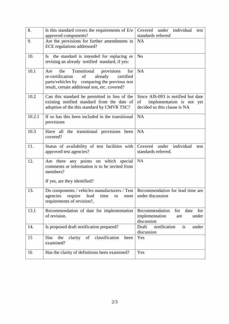
8. Is this standard covers the requirements of E/e
approved components?
Covered under individual test
standards referred
9. Are the provisions for further amendments in
ECE regulations addressed?
NA
10. Is the standard is intended for replacing or
revising an already notified standard, if yes:
No
10.1 Are the Transitional provisions for
re-certification of already certified
parts/vehicles by comparing the previous test
result, certain additional test, etc. covered?
NA
10.2 Can this standard be permitted in lieu of the
existing notified standard from the date of
adoption of the this standard by CMVR TSC?
Since AIS-093 is notified but date
of implementation is not yet
decided so this clause is NA
10.2.1 If so has this been included in the transitional
provisions
NA
10.3 Have all the transitional provisions been
covered?
NA
11. Status of availability of test facilities with
approved test agencies?
Covered under individual test
standards referred.
12. Are there any points on which special
comments or information is to be invited from
members?
If yes, are they identified?
NA
13. Do components / vehicles manufacturers / Test
agencies require lead time to meet
requirements of revision?,
Recommendation for lead time are
under discussion
13.1 Recommendation of date for implementation
of revision.
Recommendation for date for
implementation are under
discussion
14. Is proposed draft notification prepared?
Draft notification is under
discussion
15 Has the clarity of classification been
examined?
Yes
16 Has the clarity of definitions been examined?
Yes
Draft AIS-093 (Rev.1)/F
July 2014
II
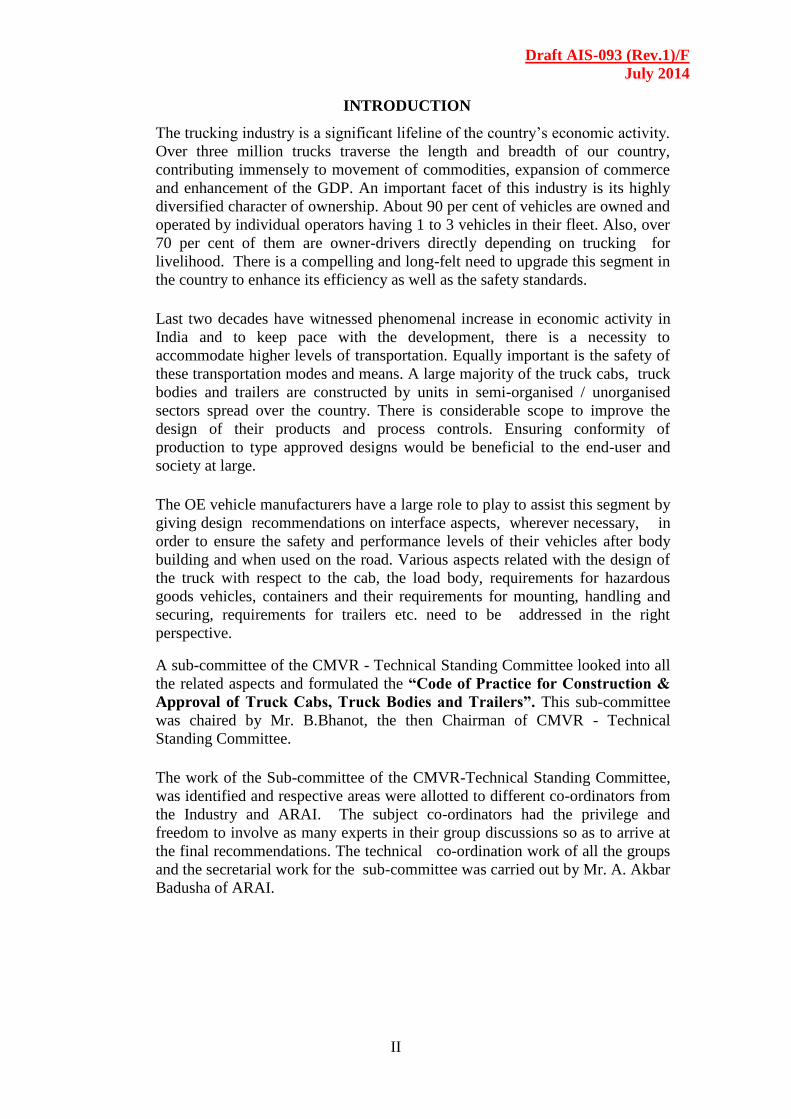
INTRODUCTION
The trucking industry is a significant lifeline of the country’s economic activity.
Over three million trucks traverse the length and breadth of our country,
contributing immensely to movement of commodities, expansion of commerce
and enhancement of the GDP. An important facet of this industry is its highly
diversified character of ownership. About 90 per cent of vehicles are owned and
operated by individual operators having 1 to 3 vehicles in their fleet. Also, over
70 per cent of them are owner-drivers directly depending on trucking for
livelihood. There is a compelling and long-felt need to upgrade this segment in
the country to enhance its efficiency as well as the safety standards.
Last two decades have witnessed phenomenal increase in economic activity in
India and to keep pace with the development, there is a necessity to
accommodate higher levels of transportation. Equally important is the safety of
these transportation modes and means. A large majority of the truck cabs, truck
bodies and trailers are constructed by units in semi-organised / unorganised
sectors spread over the country. There is considerable scope to improve the
design of their products and process controls. Ensuring conformity of
production to type approved designs would be beneficial to the end-user and
society at large.
The OE vehicle manufacturers have a large role to play to assist this segment by
giving design recommendations on interface aspects, wherever necessary, in
order to ensure the safety and performance levels of their vehicles after body
building and when used on the road. Various aspects related with the design of
the truck with respect to the cab, the load body, requirements for hazardous
goods vehicles, containers and their requirements for mounting, handling and
securing, requirements for trailers etc. need to be addressed in the right
perspective.
A sub-committee of the CMVR - Technical Standing Committee looked into all
the related aspects and formulated the “Code of Practice for Construction &
Approval of Truck Cabs, Truck Bodies and Trailers”. This sub-committee
was chaired by Mr. B.Bhanot, the then Chairman of CMVR - Technical
Standing Committee.
The work of the Sub-committee of the CMVR-Technical Standing Committee,
was identified and respective areas were allotted to different co-ordinators from
the Industry and ARAI. The subject co-ordinators had the privilege and
freedom to involve as many experts in their group discussions so as to arrive at
the final recommendations. The technical co-ordination work of all the groups
and the secretarial work for the sub-committee was carried out by Mr. A. Akbar
Badusha of ARAI.
Draft AIS-093 (Rev.1)/F
July 2014
III
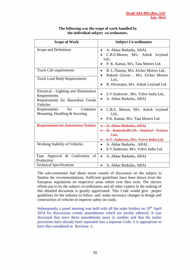
The following was the scope of work handled by
the individual subject co-ordinators.
Scope of Work Subject Co-ordinators
Scope and Definitions A. Akbar Badusha, ARAI,
C.B.S.Menon, M/s. Ashok Leyland
Ltd.,
P. K. Kamat, M/s. Tata Motors Ltd.
Truck Cab requirements B. L.Thareja, M/s. Eicher Motors Ltd.,
Rakesh Grover , M/s. Eicher Motors
Ltd.,
R. Devarajan, M/s. Ashok Leyland Ltd
Truck Load Body Requirements
Electrical - Lighting and Illumination
Requirements
S.V.Suderson , M/s. Volvo India Ltd.,
A. Akbar Badusha, ARAI Requirements for Hazardous Goods
Vehicles
Requirements for Container
Mounting, Handling & Securing C.B.S. Menon, M/s. Ashok Leyland
Ltd.,
P.K. Kamat, M/s. Tata Motors Ltd.
Requirements for Automotive Trailers A. Akbar Badusha, ARAI
B. Ramesh,M/s.PL Haulwel Trailers
Ltd.,
S.V. Suderson, M/s. Volvo India Ltd.
Working Stability of Vehicles A. Akbar Badusha , ARAI,
S.V.Suderson, M/s. Volvo India Ltd.
Type Approval & Conformity of
Production A. Akbar Badusha, ARAI
Technical Specifications A. Akbar Badusha, ARAI
The sub-committee had about seven rounds of discussion on the subject to
finalise the recommendations. Sufficient guidelines have been drawn from the
European regulations on respective areas where ever they exist. The sincere
efforts put in by the subject co-ordiinators and all other experts in the making of
this detailed document is greatly appreciated. This Code would give proper
guidelines for the industry to follow and make necessary changes in design and
construction of vehicles to improve safety on roads.
Subsequently a panel meeting was held with all the stake holders on 29th
April
2014 for discussions certain amendments which are mostly editorial. It was
discussed that since these amendments more in number and that the trailer
provisions have already been separated into a separate Code, it is appropriate to
have this considered as Revision -1.

Draft AIS-093 (Rev.1)/F
July 2014
IV
Code of Practice for Construction and Approval of
Truck Cabs, Truck Bodies and Trailers
CONTENTS
Section Details Page
No.
Section - 1 Scope and Definitions 1/156
Section - 2 Truck Cab Requirements 9/156
Section - 3 Truck Load Body Requirements 22/156
Section - 4 Electrical - Lighting and Illumination Requirements 39/156
Section - 5 Requirements for Hazardous Goods Vehicles 54/156
Section - 6 Requirements for Container Mounting, Handling & Securing 70/156
Section - 7 Requirements for Automotive Trailers 99/156
Section - 8
Working Stability of Vehicles meant for the carriage of
Hazardous goods
113/156
Section - 9 Type Approval & Conformity of Production 124/156
Section – 10 Accreditation system for Truck Cab and Body Builders
(TCBB) / Trailer Manufacturers (TM)
127/156
Annexure – I Technical Information on Truck Cab, Load Body &
Related Technical Features
128/156
Annexure – II
Technical Information of Vehicles Carrying Hazardous
Goods
141/156
Annexure – III Technical Specifications to be submitted by the Trailer
Manufacturer.
145/156
Annexure – III Composition of the Sub-Committee of CMVR-Technical
Standing Committee
156/156
Draft AIS-093 (Rev.1)/F
July 2014
1/169
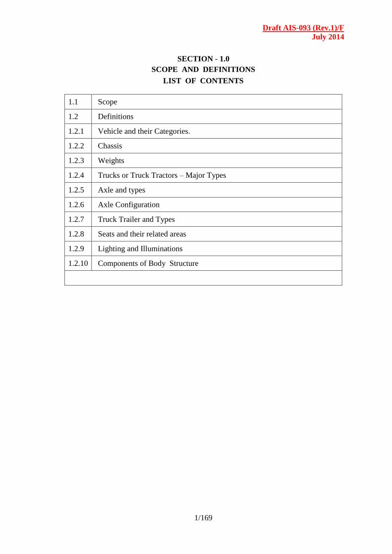
SECTION - 1.0
SCOPE AND DEFINITIONS
LIST OF CONTENTS
1.1 Scope
1.2 Definitions
1.2.1 Vehicle and their Categories.
1.2.2 Chassis
1.2.3 Weights
1.2.4 Trucks or Truck Tractors – Major Types
1.2.5 Axle and types
1.2.6 Axle Configuration
1.2.7 Truck Trailer and Types
1.2.8 Seats and their related areas
1.2.9 Lighting and Illuminations
1.2.10 Components of Body Structure

Draft AIS-093 (Rev.1)/F
July 2014
2/169
1.1 SCOPE
1.1.1 The provision of the code shall be applicable to trucks of Gross
Vehicle Weight (GVW) above 3.5 tonnes. The requirements shall not
apply to the special purpose vehicles of the following categories as
defined in CMVR, except in respect of those provisions, which are
not compatible with the intended use and function of these vehicles.
(i) Category N2
(ii) Category N3
(iii) Category T3
(iv) Category T4
1.1.2 The requirement of this code shall apply to the following types of
truck bodies used in conjunction with the categories of trucks referred
in Para1.1.1.
(i) Flat Bed or Full Open Body
(ii) Semi Open or Half Body
(iii) High Side Deck Body
(iv) Closed Body
(v) Bodies for Carrying ISO Tankers
(vi) Special Purpose Vehicles.
1.1.3 In respect of those provisions which are exclusively meant for the use
and function of special purpose vehicles, the requirements shall be
notified separately by the appropriate authorities.
1.2 DEFINITIONS The definitions stated here shall apply only for this code. These are
the definitions that may commonly apply to all the chapters of the
code.
1.2.1 Vehicle and their Categories:
1.2.1.1 “Articulated vehicle” means a vehicle, which consists of two or
more rigid sections, which articulate relative to each other, a
coupling interconnects the tractor and the super structure of
trailer or the superstructures of truck and the trailer or superstructure
of trailers. The rigid sections are permanently connected and can only
be separated by an operation involving facilities, which are
normally found in a workshop.
1.2.1.2 “Combination vehicle” means motor truck or truck tractor coupled
to one or more trailer including semi trailers.
1.2.1.3 “Tractor” means a motor vehicle designed primarily for drawing
Truck trailers and constructed so as to carry part of the weight
and load of a semi trailer.
Draft AIS-093 (Rev.1)/F
July 2014
3/169
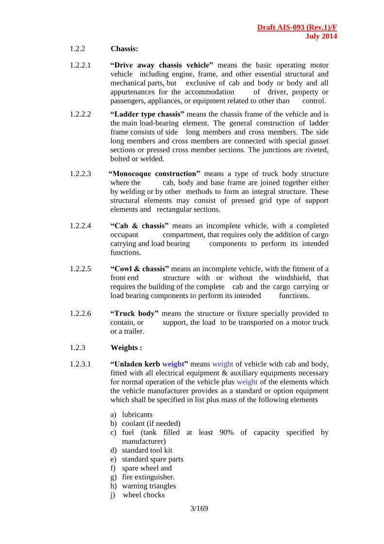
1.2.2 Chassis:
1.2.2.1 “Drive away chassis vehicle” means the basic operating motor
vehicle including engine, frame, and other essential structural and
mechanical parts, but exclusive of cab and body or body and all
appurtenances for the accommodation of driver, property or
passengers, appliances, or equipment related to other than control.
1.2.2.2 “Ladder type chassis” means the chassis frame of the vehicle and is
the main load-bearing element. The general construction of ladder
frame consists of side long members and cross members. The side
long members and cross members are connected with special gusset
sections or pressed cross member sections. The junctions are riveted,
bolted or welded.
1.2.2.3 “Monocoque construction” means a type of truck body structure
where the cab, body and base frame are joined together either
by welding or by other methods to form an integral structure. These
structural elements may consist of pressed grid type of support
elements and rectangular sections.
1.2.2.4 “Cab & chassis” means an incomplete vehicle, with a completed
occupant compartment, that requires only the addition of cargo
carrying and load bearing components to perform its intended
functions.
1.2.2.5 “Cowl & chassis” means an incomplete vehicle, with the fitment of a
front end structure with or without the windshield, that
requires the building of the complete cab and the cargo carrying or
load bearing components to perform its intended functions.
1.2.2.6 “Truck body” means the structure or fixture specially provided to
contain, or support, the load to be transported on a motor truck
or a trailer.
1.2.3 Weights :
1.2.3.1 “Unladen kerb weight” means weight of vehicle with cab and body,
fitted with all electrical equipment & auxiliary equipments necessary
for normal operation of the vehicle plus weight of the elements which
the vehicle manufacturer provides as a standard or option equipment
which shall be specified in list plus mass of the following elements
a) lubricants
b) coolant (if needed)
c) fuel (tank filled at least 90% of capacity specified by
manufacturer)
d) standard tool kit
e) standard spare parts
f) spare wheel and
g) fire extinguisher.
h) warning triangles
j) wheel chocks
Draft AIS-093 (Rev.1)/F
July 2014
4/169
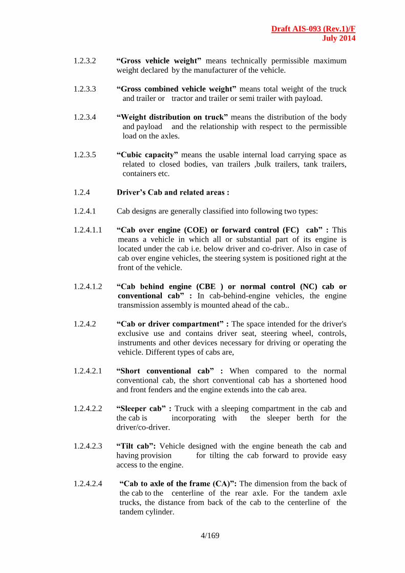
1.2.3.2 “Gross vehicle weight” means technically permissible maximum
weight declared by the manufacturer of the vehicle.
1.2.3.3 “Gross combined vehicle weight” means total weight of the truck
and trailer or tractor and trailer or semi trailer with payload.
1.2.3.4 “Weight distribution on truck” means the distribution of the body
and payload and the relationship with respect to the permissible
load on the axles.
1.2.3.5 “Cubic capacity” means the usable internal load carrying space as
related to closed bodies, van trailers ,bulk trailers, tank trailers,
containers etc.
1.2.4 Driver’s Cab and related areas :
1.2.4.1 Cab designs are generally classified into following two types:
1.2.4.1.1 “Cab over engine (COE) or forward control (FC) cab” : This
means a vehicle in which all or substantial part of its engine is
located under the cab i.e. below driver and co-driver. Also in case of
cab over engine vehicles, the steering system is positioned right at the
front of the vehicle.
1.2.4.1.2 “Cab behind engine (CBE ) or normal control (NC) cab or
conventional cab” : In cab-behind-engine vehicles, the engine
transmission assembly is mounted ahead of the cab..
1.2.4.2 “Cab or driver compartment” : The space intended for the driver's
exclusive use and contains driver seat, steering wheel, controls,
instruments and other devices necessary for driving or operating the
vehicle. Different types of cabs are,
1.2.4.2.1 “Short conventional cab” : When compared to the normal
conventional cab, the short conventional cab has a shortened hood
and front fenders and the engine extends into the cab area.
1.2.4.2.2 “Sleeper cab” : Truck with a sleeping compartment in the cab and
the cab is incorporating with the sleeper berth for the
driver/co-driver.
1.2.4.2.3 “Tilt cab”: Vehicle designed with the engine beneath the cab and
having provision for tilting the cab forward to provide easy
access to the engine.
1.2.4.2.4 “Cab to axle of the frame (CA)”: The dimension from the back of
the cab to the centerline of the rear axle. For the tandem axle
trucks, the distance from back of the cab to the centerline of the
tandem cylinder.
Draft AIS-093 (Rev.1)/F
July 2014
5/169
1.2.4.2.5 “Cab to end of the frame (CE)”: The dimension from the back of
the cab to the rear of the standard frame.
1.2.4.2.6 “Door” means a sub system of a Truck cab body that permits
boarding and alighting for the driver and crew members.
1.2.4.2.7 “Window” means an aperture in the side or rear of the truck cab to
let in light / air.
1.2.4.2.8 “A pillar” means a structural member integrating the floor, waist
rail (bottom of windscreen panel) and roof.
1.2.5 Axle and Types:
1.2.5.1 “Axle” for the purpose of defining a vehicular wheel arrangement
may be composed of either:
(i) One beam extending across the vehicle and mounting at each
end either a single wheel, a pair of dual disc wheels, or a
demountable rim type wheel with dual rims; or
(ii) Two separate and independently suspended beams located
transversely across the vehicle and each mounting one of the
aforementioned wheel arrangements. In either case, two single
wheels or two dual wheel arrangements are considered the
complement of any axle depending on whether single or dual
tires are used.
1.2.5.2 “Non-powered axle” means an axle designed to support the portion
of the vehicle weight but does not transmit a driving force to the
wheels.
1.2.5.3 “Powered axle” means an axle designed to support a portion of the
vehicle weight and to transmit a driving torque / force to wheels.
1.2.5.4 “Steering axle” means an axle through which directional control of
the vehicle is applied. A steering axle may be powered or non-
powered.
1.2.5.5 “Two-axle group” means a tandem axle and a “Tri-axle group”
means a tridem axle. By convention a solo axle is considered as a
group of one axle.
1.2.5.6 “Axle- lift device” means a device permanently fitted to a vehicle
for the purpose of reducing or increasing the load on the axle(s),
according to the loading conditions of the vehicle:
- Either by raising the wheels clear off the ground / lowering them to
the ground, or
- Without raising the wheels off the ground, ( e.g, in the case of air
suspension systems, or other systems),
Draft AIS-093 (Rev.1)/F
July 2014
6/169
in order to reduce the wear on the tyres, when the vehicle is not
fully laden, and /or make starting ( moving off) on slippery ground
easier for motor vehicles or vehicle combinations, by increasing the
load on the driving axle.
1.2.5.7 “Retractable axle” means an axle which can be raised / lowered
by the axle lift device in accordance with 1.2.5.6, first indent.
1.2.6 Axle configuration :
(Figures indicate the number of load-bearing wheels times the number
of driving wheels)
1.2.6.1 4x2 Tandem-axle truck with drive on one rear axle.
1.2.6.2 4x4 Tandem-axle truck with drive on two axles.
1.2.6.3 6x2 Tri-axle truck with drive on one rear axle.
1.2.6.4 6x2/4 Tri-axle truck with drive on one rear axle and one tag axle, with
steered wheels in front of the driving axle.
1.2.6.5 6x2/4 Tri-axle truck with drive on one rear axle and one tag axle, with
steered wheels behind the driving axle.
1.2.6.6 6x4 Tri-axle truck with drive on two rear axles.
1.2.6.7 6x6 Tri-axle truck with drive on three axles.
1.2.6.8 8x2 Four-axle truck with twin front axles and with drive on one rear
axle.
1.2.6.9 8x2/4 Four-axle truck with drive on one rear axle and one tag axle,
with steered wheels in front of the driving axle.
1.2.6.10 8x2/6 Four-axle truck with twin front axles and drive on one rear axle
and one tag axle, with steered wheels behind the driving rear axle.
1.2.6.11 8x4 Four-axle truck with twin front axles and with drive on two rear
axles.
1.2.6.12 8x8 Four-axle truck with drive on four axles.
1.2.7 Truck Trailer and Types :
1.2.7.1 “Truck trailer” means a vehicle with or without auxiliary motive
power designed to be drawn by a motor truck or truck tractor.
1.2.7.2 “Semi-trailer” means a truck trailer equipped with one or more
axles, and so constructed that the front end and a substantial part of its
own weight and that of its load rest upon another vehicle.
1.2.7.3 “Full trailer” means a truck trailer constructed so that all its own
weight and that of its load rest upon its own wheels.
Draft AIS-093 (Rev.1)/F
July 2014
7/169
1.2.7.4 “Load dividing dolly” is coupled between a Truck Tractor and semi-
trailer to reduce the load imposed by the semi-trailer on the truck
tractor. It is a truck trailer with one or more axles equipped with a
fifth wheel, drawbar, and other parts necessary for its use.
1.2.7.5 “Trailer converter dolly” means a truck trailer with one or more
axles equipped with a fifth wheel, a draw bar, and other parts
necessary to convert a semi-trailer to a full trailer.
1.2.8 Seats and their related areas : All the related definitions for seats
and their areas defined in AIS-023 shall be applicable.
1.2.9 Lighting and Illumination :
1.2.9.1 “Cab lamp or courtesy lamp” are lamps situated above the head of
the driver lighting up the dash board area and inside of the cab. This
is meant for operation while the vehicle is stationary. The cab lamp
shall be capable of being operated only for a momentary duration
while the vehicle is in motion.
1.2.9.2 “Instrument lighting” are lights that light up individual instruments.
These can be connected to a single control through a rheostat or any
other suitable means. By varying the control, the strength of the
instrument lighting can be regulated by the driver while driving in the
dark to avoid glare from instrument lighting.
1.2.9.3 “Control unit lamps” are similar to instrument lighting. However,
these lamps illuminate individual controls discreetly to assist driver
for identifying the controls.
1.2.9.3.1 “Locker lamps” are lamps to light up the inside of the locker when
the door to the locker is opened, illuminating the interior of the
locker.
1.2.9.4 “Electrical distribution panel lamps” are lamps meant to light up
electrical distribution panel when the cover to the distribution center
is opened for checking and maintenance purposes.
1.2.10 Components of Body Structure :
1.2.10.1 “Cross bearers” are structural members mounted on the chassis
frame or to the long member through ‘U’ Bolts, gussets or out rigger
brackets. The cross bearers transmit the body load to the chassis or to
through the long member and also withstand the forces induced
during the normal operation of the vehicle.
1.2.10.2 “Vertical pillars” (body pillar) are structural members that support
the side structure are connected to the cross bearers through gussets.
The side pillars transmit load to the cross bearers and also withstand
the forces induced during the normal operation of the vehicle.
1.2.10.3 “Long member” are structural members that support the cross
bearers and helps to transmit the load from cross bearers to the
chassis.
Draft AIS-093 (Rev.1)/F
July 2014
8/169
1.2.10.4 “U bolts” are fasteners used for fastening the cross bearers to the
chassis frame.
1.2.10.5 “Outrigger” Members are provided to transfer load of Body structure
members. These are fixed to the chassis side members.
1.2.10.6 “Rear gate(s) (Rear doors/tail gate)” are structural members that are
provided for protecting the load and also act as load bearing members
to support the load. The rear doors also transmit load to the load and
also withstand the forces induced during the normal operation
1.2.10.7 “Head board (also called crash guard or front wall)” are structural
members that are provided for supporting the load and act as load
bearing members. (Headboard, can be treated as part of the load
restraint system)
1.2.10.8 “Floor board” (Platform) are structural members that are provided
for supporting the load and act as load bearing members and are
capable of withstanding a vertical forces acting on it during normal
operation.
1.2.10.9 “Side board” (Side gates) are structural members that are provided
for supporting the load and act as load bearing members and are
capable of withstanding a horizontal forces(Side thrust) induced on it
during normal operation. Side boards also transmit roof load in case
of closed body or containers.
1.2.10.10 “Bolster” Rigid support base commonly used to support logs.
1.2.10.11 “Blocking” Material, usually timber, placed between the load and the
vehicle structure, used to prevent movement of the load. (Also
Baulking - “blocking”)
1.2.10.12 “Chocks” Blocks, normally wedge shaped, used to prevent
movement of the truck wheels.
1.2.10.13 “Dunnage” Packing placed between the base of the load and the
surface of the vehicle’s load platform. See also “blocking”.
1.2.10.14 “Frail” A frame for holding sheets of glass during transport.
1.2.10.15 “Lashings” Fastening devices, chains, cables, ropes or webbing used
to restrain loads.
1.2.10.16 “Load binder” A device fitted to a chain or lashing used to tighten
(tension) the restraint. An over-centre locking action is
incorporated.
1.2.10.18 “Shackle” A metal coupling link closed by a bolt, which can be used
for connecting chains to anchor points. The two principal shapes are
“D” and “bow”.
Draft AIS-093 (Rev.1)/F
July 2014
9/169
1.2.10.19 “Shoring bar” Metal or wooden load-carrying beam or fabricated
truss section used to restrain or transmit a load from one frame,
column, post, wall or bearing point to another. It may be adjustable
and also can be known as a shoring pole.
1.2.10.20 “Thimble” A metal liner, usually pear-shaped and concave on the
outside which is fitted into the eye of a rope to prevent chafing and to
distribute the load.
1.2.10.21 “Turnbuckle” A type of coupling fitted between the ends of a
lashing or between two lashings used primarily for adjusting or
regulating the tension in lashings. It consists of a loop or sleeve with a
screw thread on one end and a swivel at the other. Alternatively, it has
an internal screw thread at each end.
1.2.10.22 “Twist lock” A locking device designed to fasten containers to the
vehicle on which they are being transported.
1.2.10. 23 “Crew members” means any person(s) assigned to support the
operation of the vehicle.
Note : In case if any of the above mentioned definitions are at variance with
the notified definitions under Central Motor Vehicle Rules, 1989, the
later shall be considered to have the final standing for all technical
and administrative purposes.
Draft AIS-093 (Rev.1)/F
July 2014
10/169
SECTION - 2.0
TRUCK CAB REQUIREMENTS LIST OF CONTENTS
2.1 General Requirements
2.1.1 Overall Dimensions
2.1.2 External Projections
2.1.3 Driver Door
2.1.4 Climb Facility
2.1.5 Hand Holds
2.1.6 Window on Cab Door
2.1.7 Driver Seat / Co-Passenger Seat
2.1.8 Safety Belt Assemblies and Anchorages
2.1.9 Sleeper Berth
2.1.10 Mudguards
2.1.11 Driver Work Area
2.1.12 Steering Wheel
2.1.13 Placement of Instrument Panel
2.1.14 Position of Controls
2.1.15 Stowage Space
2.1.16 First Aid Box
2.1.17 Heating, Cooling and Ventilation for Driver
2.2 Truck Cab – Technical and Safety Requirements
2.2.1 Truck Cab Structural Strength
2.2.2 Front Under run Protective Device
2.2.3 Cab Mounting Arrangement and Strength Requirements
2.2.4 Protection of the Occupants in the Event of a Lateral Collision
2.2.5 Cab Mountings for Tilting type cabs
2.2.6 Lighting and Signaling Devices
2.2.7 Rear view mirror
2.2.8 Driver’s Work Area
2.2.9 Door Locks & Hinges
2.2.10 Window
2.2.11 Ingress of dust and rain water
2.2.12 Wind Screen and Wind Screen Wiping System
2.2.13 Fire extinguishers
2.2.14 Guidelines for Corrosion Protection

Draft AIS-093 (Rev.1)/F
July 2014
11/169
2.1 General requirements of truck cab design :
2.1.1 Overall dimensions : The overall dimensions of the truck cab shall
comply with the provisions laid down in Rule 93 of the Central Motor
Vehicle Rules, 1989 as amended from time to time.
2.1.2 External projections : The cab shall comply with the external
projection requirements as per IS 13942:1994, as laid down in Rule 124
of the Central Motor Vehicles Rules, 1989, as amended from time to
time.
2.1.3 Driver door :
2.1.3.1 All truck cabs shall be provided with minimum two entries one for
the driver and one for the co-passenger, on either sides of vehicle.
2.1.3.2 The driver and co-passenger doors shall be hinged from A-Pillar.
2.1.3.3 All doors shall be hinged at the front and shall open minimum by 65º.
An opening of 650 mm minimum must be available from ‘B’-Pillar, in
the fully open condition.
2.1.3.4 The minimum height of the door aperture (clear opening) measured
from floor to the top shall not be less than 1050 mm. In case of floor
with hump, the minimum height shall be measured as clear max
opening. (Refer Q in Figure - 2).
2.1.3.5 The minimum width of the door aperture measured from A Pillar to B
Pillar shall be 650 mm. (Refer P in Figure - 2)
2.1.4 Climb facility : The requirements of Climb facility are as given in the
table under Figure-3.
2.1.4.1 The maximum height (a) from ground to top surface of first step shall be
650 mm measured on vehicle in unladen condition. However, in case of
off- road vehicles this dimension shall not be more than 700mm.
2.1.4.2 The vertical distance (b) between top surface of subsequent steps shall
not be more than 400mm. The vertical distance between two subsequent
steps shall not vary by more than 50 mm. The last requirement shall not
apply to the distance between the uppermost step and the cab floor. For
off-road vehicles, this latter value may be increased up to 100 mm and
the dimension (b) shall not be more than 500 mm.
2.1.4.3 The lowest step may be designed as a rung, if this is necessary for
reasons relating to construction or use, and in the case of off road
vehicles. The rung depth thickness (t) shall be at least 20 mm or it
shall be capable of withstanding minimum 140 kgf load. Rungs of
round cross section are not permitted.
2.1.4.4 In addition, the following geometrical specifications shall be fulfilled:
Minimum step width (f) shall be 200 mm.
Minimum step width (g) for lower step shall be 100mm
Draft AIS-093 (Rev.1)/F
July 2014
12/169
Minimum step depth (d) shall be 80 mm.
Minimum step clearance including step depth (e) shall be 150 mm
Minimum height of uppermost step to floor (s) shall be 120 mm
2.1.4.5 Other requirements shall be as per the table under Figure - 3.
2.1.4.6 Steps need be provided with anti-slip surface, as per the relevant AIS as
and when notified. In addition, steps exposed to weather and dirt during
driving shall have adequate run off (draining surface).
NOTE: In case if there are any contradictory requirements between the
requirements stated in this code and that of AIS 046, the requirements
stated in AIS 046 may be considered as final and standing.
2.1.5 Hand holds :
2.1.5.1 The handhold requirements shall comply with AIS-046 as amended
from time to time.
2.1.5.2 Figure - 3 may be referred for guidelines.
2.1.6 Window on cab door :
2.1.6.1 The window panes shall be winding type for all trucks.
2.1.6.2 The minimum width of the window aperture (clear vision zone) shall be
450 mm.
(Refer R in Figure - 2) and the minimum height of the window aperture
(clear vision zone) shall be 400 mm. (Refer S in Figure - 2).
Alternatively, the total area of the aperture shall not be less than 1800
sq. cm.
2.1.7 Driver seat / Co-occupant Seat : Driver / Co-driver seat shall comply
with the requirements specified in AIS-023-“Automotive Vehicles –
Seats, their Anchorages and Head Restraints” "Automotive
Vehicles - Seats, their Anchorages and Head Restraints for
Passenger Vehicles of Categories M2, M3 and Goods Vehicles of
Category N - Specifications", as amended from time to time.
2.1.8 Safety belt assemblies and anchorages : Safety belt assemblies and
anchorages shall comply with the requirements laid in IS: 15140-2003
and IS 15139-2002 AIS-005 and AIS-015 respectively as and when
notified separately under CMVR.
2.1.9 Sleeper berth :
2.1.9.1 The sleeper berth (wherever provided) shall be located within the cab.
No sleeper berth shall be permitted in the cargo area.
2.1.9.2 The sleeper berth shall be so constructed as to provide minimum length
of 1750 mm measured along the longitudinal median axis of the berth.
Figure - 2 of the section may be referred.
Draft AIS-093 (Rev.1)/F
July 2014
13/169
2.1.9.3 The sleeper berth shall have minimum width of 500 mm at least over the
length of 1200 mm and 400 mm for the remainder. (Refer K in Figure –
2 ).
2.1.9.4 The edges of the berth may be rounded to radii not exceeding 270 mm.
2.1.9.5 In case twin berth have been one above the other, the minimum pitch
between the two berths (measured from top face of the lower berth with
uncompressed cushion and lower face of the upper berth) shall be as
follows ( Refer J in Figure-2) –
In case the upper berth is folding type - 490 mm
In case the upper berth is fixed type - 770 mm
2.1.9.6 The minimum distance between the roof and the upper berth, measured
from top face of the berth with uncompressed cushion shall be 490
mm. Refer ‘I’ in Figure - 2.
2.1.10 Mudguards / Spray suppression devices : The tyres of motor vehicles
shall be enveloped with effective mudguards. The mudguards may be
mounted on cab Floor or sides or any part of the chassis frame. In
addition, the vehicles shall be fitted with spray suppression devices in
accordance with AIS-013, relevant for the categories of vehicles
specified therein.
2.1.11 Driver’s work area :
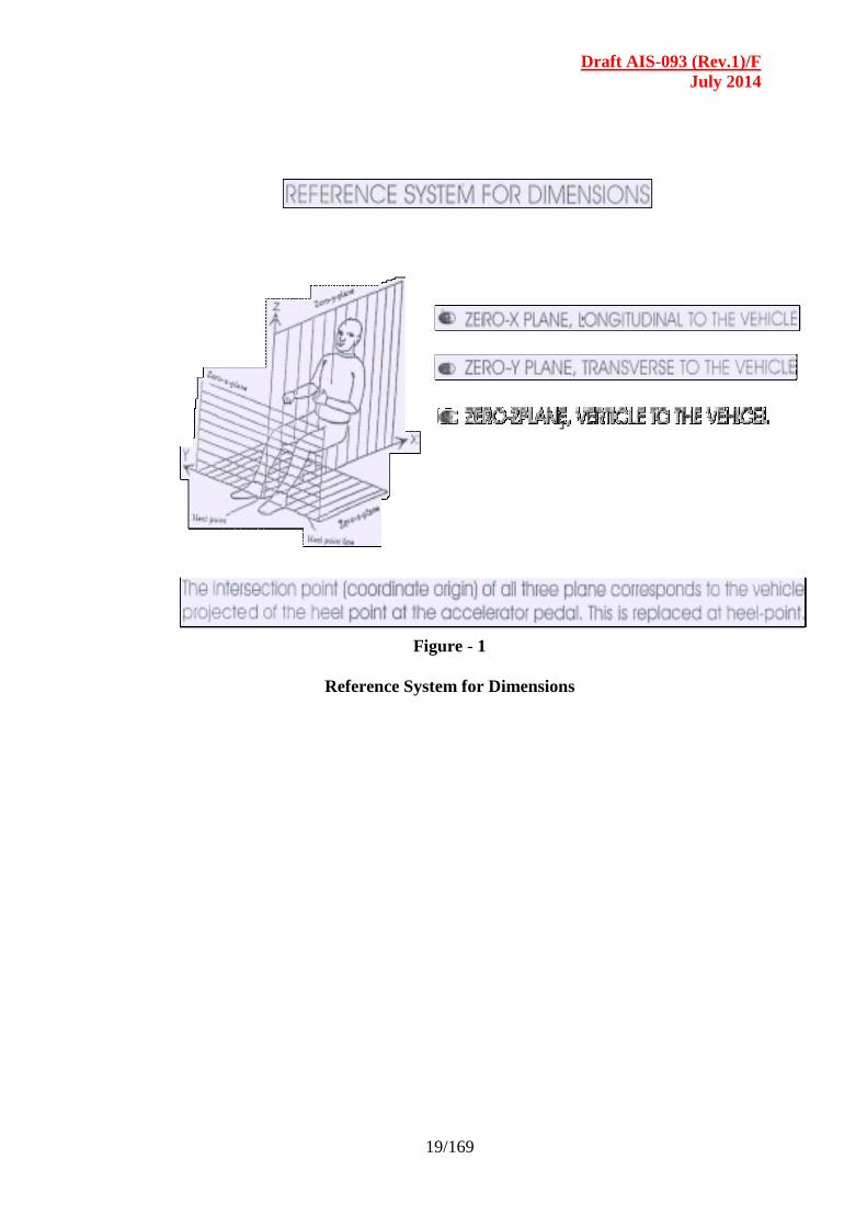
2.1.11.1 Reference system for dimensions : The intersection point (co-ordinate
origin) of all the three planes corresponds to the vehicle projected at the
heel point of the accelerator pedal. Figure 1 may be referred.
2.1.11.2 Heel point : Heel point shall be located at a minimum distance of 300
mm from the inner face of the bulkhead. (Refer ‘Z’ in Figure-2)
2.1.11.3 Reference point : The “H” Point (Reference Point) shall be specified
by the chassis manufacturer. The minimum distance of driver partition
from the driver seat shall be 15 mm from the rearmost point of the driver
seat in its rearmost position with seat back reclined backwards to an
angle of 12 degrees. The minimum distance from H – point to roof
top measured along the backrest at 12 degree angle shall be 900
mm.(Refer ‘Y’ in Figure-2(a)
2.1.12 Steering wheel : The chassis manufacturer shall specify the position of
the steering wheel with reference to the heel point. An adjustment
range of minimum 60mm shall be provided for the thigh clearance (i.e.
the vertical distance measured between the top of seat cushion and
bottom of the steering wheel – Refer ‘W’ in Figure - 2). This may be
provided by way of adjustment in Seat Position or Steering Wheel
position or combination of both. A minimum thigh clearance of 170mm
shall be achievable in the adjustment range provided. The minimum
distance of lower end of steering wheel from driver seat back shall be
265 mm. (Refer ‘N’ in Figure - 2)
Draft AIS-093 (Rev.1)/F
July 2014
14/169
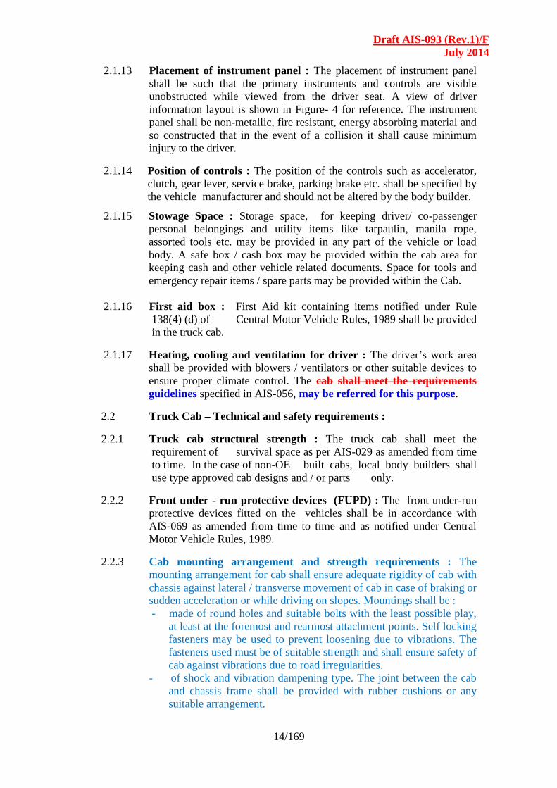
2.1.13 Placement of instrument panel : The placement of instrument panel
shall be such that the primary instruments and controls are visible
unobstructed while viewed from the driver seat. A view of driver
information layout is shown in Figure- 4 for reference. The instrument
panel shall be non-metallic, fire resistant, energy absorbing material and
so constructed that in the event of a collision it shall cause minimum
injury to the driver.
2.1.14 Position of controls : The position of the controls such as accelerator,
clutch, gear lever, service brake, parking brake etc. shall be specified by
the vehicle manufacturer and should not be altered by the body builder.
2.1.15 Stowage Space : Storage space, for keeping driver/ co-passenger
personal belongings and utility items like tarpaulin, manila rope,
assorted tools etc. may be provided in any part of the vehicle or load
body. A safe box / cash box may be provided within the cab area for
keeping cash and other vehicle related documents. Space for tools and
emergency repair items / spare parts may be provided within the Cab.
2.1.16 First aid box : First Aid kit containing items notified under Rule
138(4) (d) of Central Motor Vehicle Rules, 1989 shall be provided
in the truck cab.
2.1.17 Heating, cooling and ventilation for driver : The driver’s work area
shall be provided with blowers / ventilators or other suitable devices to
ensure proper climate control. The cab shall meet the requirements
guidelines specified in AIS-056, may be referred for this purpose.
2.2 Truck Cab – Technical and safety requirements :
2.2.1 Truck cab structural strength : The truck cab shall meet the
requirement of survival space as per AIS-029 as amended from time
to time. In the case of non-OE built cabs, local body builders shall
use type approved cab designs and / or parts only.
2.2.2 Front under - run protective devices (FUPD) : The front under-run
protective devices fitted on the vehicles shall be in accordance with
AIS-069 as amended from time to time and as notified under Central
Motor Vehicle Rules, 1989.
2.2.3 Cab mounting arrangement and strength requirements : The
mounting arrangement for cab shall ensure adequate rigidity of cab with
chassis against lateral / transverse movement of cab in case of braking or
sudden acceleration or while driving on slopes. Mountings shall be :
- made of round holes and suitable bolts with the least possible play,
at least at the foremost and rearmost attachment points. Self locking
fasteners may be used to prevent loosening due to vibrations. The
fasteners used must be of suitable strength and shall ensure safety of
cab against vibrations due to road irregularities.
- of shock and vibration dampening type. The joint between the cab
and chassis frame shall be provided with rubber cushions or any
suitable arrangement.
Draft AIS-093 (Rev.1)/F
July 2014
15/169
2.2.3.1 Fixed cabs : The cab mountings shall be supported with rubber
cushions and/or leaf spring with adequate lateral and longitudinal
stiffness. When “U” bolts are employed to secure the cab to the chassis
frame, spacers / stiffeners shall be used between the flanges of side-
members to prevent buckling.
2.2.3.2 Tiltable cabs - Tilting mechanism, Locking requirements : Suitable
locking arrangement shall be provided to hold the cab in the tilted
condition either automatically or by means of a retaining device. The
provision shall have stopper along with locking arrangement, which can
be disengaged with manual intervention only. The stopper shall be able
to hold the weight of loaded cab with adequate safety margin. In case
where the effort required to lift the cab is high, suitable arrangements
shall be provided to assist the lifting. Additional assistance may be
provided through hydraulic or mechanical means or any such suitable
arrangement. In the case of locally built cabs, OE approved designs and
parts shall be used or else the locally developed designs shall be type
approved by the authorised agency. Vehicle manufacturer shall provide
details of recommended practices for cab mounting including list of
approved parts. In any of these cases, no part of chassis shall be altered
so as to affect its stability or any other safety aspects including wiring
harness, brake circuits etc.
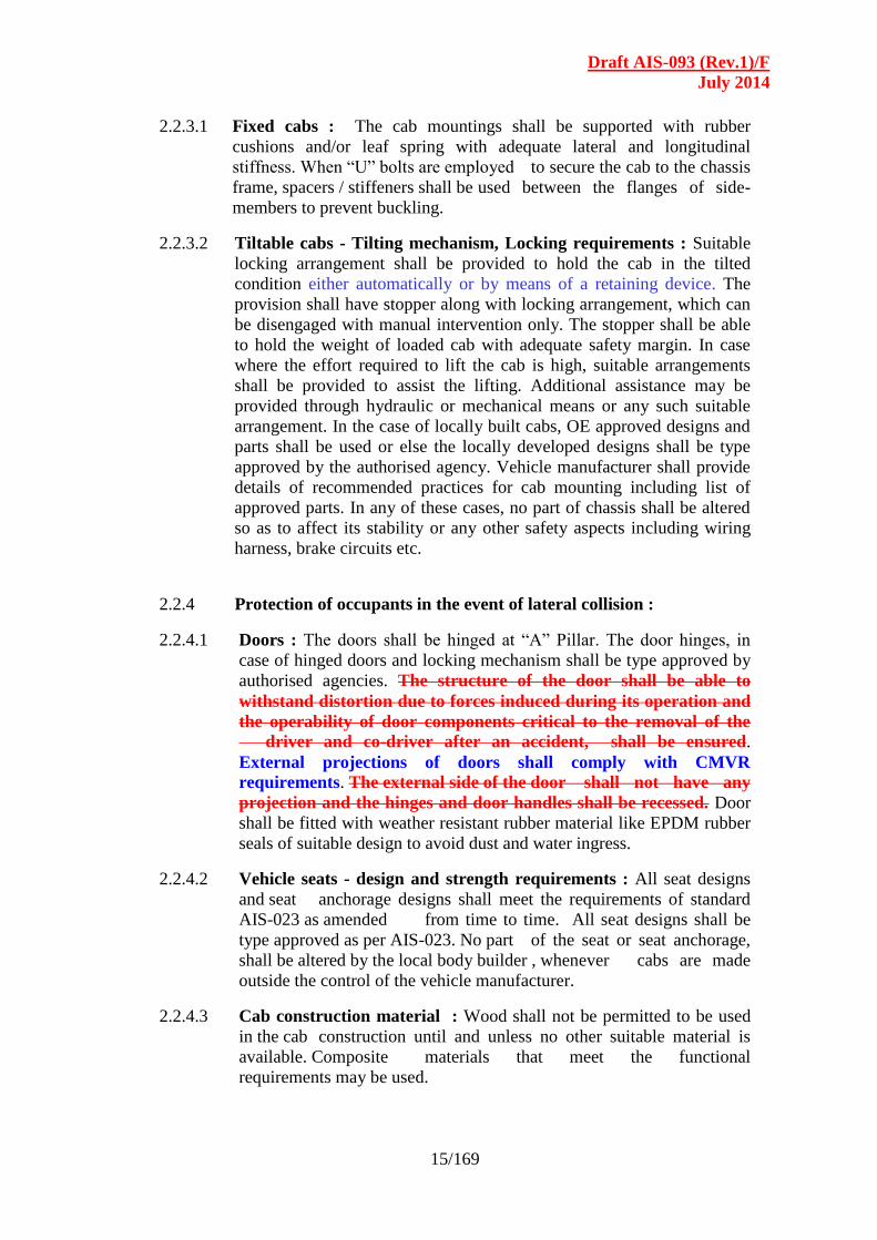
2.2.4 Protection of occupants in the event of lateral collision :
2.2.4.1 Doors : The doors shall be hinged at “A” Pillar. The door hinges, in
case of hinged doors and locking mechanism shall be type approved by
authorised agencies. The structure of the door shall be able to
withstand distortion due to forces induced during its operation and
the operability of door components critical to the removal of the
driver and co-driver after an accident, shall be ensured.
External projections of doors shall comply with CMVR
requirements. The external side of the door shall not have any
projection and the hinges and door handles shall be recessed. Door
shall be fitted with weather resistant rubber material like EPDM rubber
seals of suitable design to avoid dust and water ingress.
2.2.4.2 Vehicle seats - design and strength requirements : All seat designs
and seat anchorage designs shall meet the requirements of standard
AIS-023 as amended from time to time. All seat designs shall be
type approved as per AIS-023. No part of the seat or seat anchorage,
shall be altered by the local body builder , whenever cabs are made
outside the control of the vehicle manufacturer.
2.2.4.3 Cab construction material : Wood shall not be permitted to be used
in the cab construction until and unless no other suitable material is
available. Composite materials that meet the functional
requirements may be used.

Draft AIS-093 (Rev.1)/F
July 2014
16/169
2.2.4.4 Panels (exterior and interior) : The exterior and interior panel surfaces
of cab shall be protected against corrosion. If suitable material is not
available then the surfaces shall be coated with corrosion preventing
paint.
2.2.4.5 Roof luggage carrier : No luggage shall be permitted to be carried on
the roof of the cab. If any provision is to be made, the mounting of the
same shall not be provided on the cab. If, for any reason the luggage
carrier is made on cab roof, it shall not rest on the roof. It shall be
supported on channels that get linked to the “A” and “B” pillars. Any
such structure shall meet the following strength requirements.
- Uniformly distributed static load of 150 kgf / m2
- Inertia forces equivalent of 2.5 g.
- Shear force equivalent to 1.5 g.
Further, the maximum load capacity of such a stowage space shall be
specified on a plate fitted outside the stowage space. At any point of
time, load shall not be transferred to the cab.
2.2.5 Cab mountings for tilting type cabs :
2.2.5.1 Cab in raised position : The cab shall be capable of being held in the
raised position either automatically or by means of a retaining device.
2.2.5 Lighting and signaling devices : The lighting and signaling devices
on the truck cab shall meet the requirements specified in AIS-008
and as amended from time to time. Only type approved parts or
recommended parts and Installation shall be used when the cab is made
by local body builders.
2.2.6 Rear view mirrors : The rear view mirrors shall be provided and shall
meet the requirements specified in AIS-001 and AIS-002 as amended
from time to time.
2.2.6.1 Interior rear view mirror :. The location, make, type and size of the
interior rear view mirror, if fitted, shall be the one which is approved by
the test agency.
2.2.7 Driver’s work area : No part of the vehicle’s fixed components shall
intrude into the Driver’s Work Area.
2.2.8 Door locks and hinges : Door components such as door locks and
hinges shall meet the requirements specified in IS : 14225-1995, under
Rule 124 of the Central Motor Vehicles Rules, 1989, as amended from
time to time.
2.2.9 Window :
2.2.9.1 Window type : Cab windows on doors shall be of winding type. Other
windows may be sliding type, fixed type or with partial opening type.
2.2.9.2 Window glass : The window glass shall be made of safety glass as
specified in IS : 2553 (Part 2) and shall readily break on impact (such as
a stroke of a hammer) in the event of an accident.
Draft AIS-093 (Rev.1)/F
July 2014
17/169
2.2.9.3 Thickness of glass : The minimum glass thickness shall be 3.5 mm for
windows.
2.2.9.4 Edges of glazing : The edge shall be crown edge, satin finish for all the
exposed edges that is likely to come in touch with the person’s body.
This edge specification corresponds to Edge No. 1 specified in
SAE J673.
2.2.9.5 Window frames for other than door windows : The glazing may be
mounted on frame; constructed from aluminum extrusions or formed
steel / coated sections. Alternately directly, sliding on flocked rubber
channels supported by aluminum/steel section. The window frames
shall be mounted such that distortions and change of aperture
dimensions due to forces on the structure does not deform the guide
way. The window glass/glass and frame shall slide smoothly when
subjected to normal pull force (50 to 75N). The window frame shall
be attached to the structure by weather strips or bonded with
adhesive or any other suitable method. The mounting shall meet
requirement specified in IS : 13944- 1995 - Window retention and
release system for safety Requirement. The window frame glazing
and accessories shall meet the performance and durability
requirements specified in AIS-068 standard as and when notified.
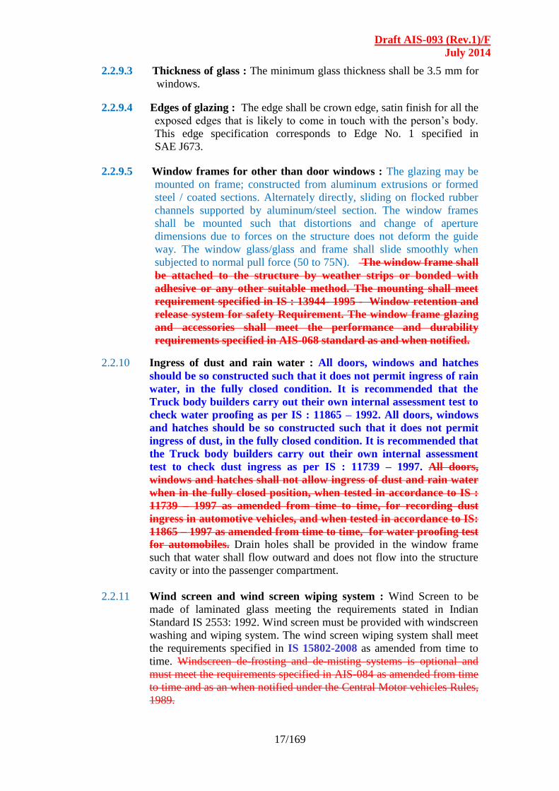
2.2.10 Ingress of dust and rain water : All doors, windows and hatches
should be so constructed such that it does not permit ingress of rain
water, in the fully closed condition. It is recommended that the
Truck body builders carry out their own internal assessment test to
check water proofing as per IS : 11865 – 1992. All doors, windows
and hatches should be so constructed such that it does not permit
ingress of dust, in the fully closed condition. It is recommended that
the Truck body builders carry out their own internal assessment
test to check dust ingress as per IS : 11739 – 1997. All doors,
windows and hatches shall not allow ingress of dust and rain water
when in the fully closed position, when tested in accordance to IS :
11739 – 1997 as amended from time to time, for recording dust
ingress in automotive vehicles, and when tested in accordance to IS:
11865 – 1997 as amended from time to time, for water proofing test
for automobiles. Drain holes shall be provided in the window frame
such that water shall flow outward and does not flow into the structure
cavity or into the passenger compartment.
2.2.11 Wind screen and wind screen wiping system : Wind Screen to be
made of laminated glass meeting the requirements stated in Indian
Standard IS 2553: 1992. Wind screen must be provided with windscreen
washing and wiping system. The wind screen wiping system shall meet
the requirements specified in IS 15802-2008 as amended from time to
time. Windscreen de-frosting and de-misting systems is optional and
must meet the requirements specified in AIS-084 as amended from time
to time and as an when notified under the Central Motor vehicles Rules,
1989.

Draft AIS-093 (Rev.1)/F
July 2014
18/169
2.2.12 Fire extinguishers : The vehicle shall be equipped with one or more
fire extinguishers, one being near to the driver’s seat. Provision of at
least one fire extinguisher shall be compulsory made for all kind of
trucks. Special provisions should be made for the trucks carrying
explosive materials. Halogenated hydrocarbon type of extinguisher
shall not be used as extinguishant. The fire extinguishers shall be
secured against tampering and shall be easily accessible to incumbent.
Also the location shall be marked clearly.
2.2.13 Guidelines for corrosion protection : The quality of the surface
treatment shall be tested according to the test methods specified in
JIS:D0202 or any equivalent Indian / International standards. The
minimum quality requirements in table below may be met for test
criteria specified in Para. 9 4 of JIS D0202.
Item Quality
Surface Condition –Appearance There must be no surface roughness,
pin holes or other harmful defects.
Corrosion
Resistance
Iron Phosphate
treatment
72 (Hrs)
Zinc Phosphate
treatment
96 (Hrs)
Water and moisture
Resistance
Iron Phosphate
treatment
36 (Hrs)
Zinc Phosphate
treatment
48 (Hrs)
Oil Resistance (40 Deg. 24 hrs)h No swelling, flaking, peeling, cracking,
film softening nor appreciable change
in lustre or colour
Volatile Oil Resistance (Gasoline) (24
hrs)
No swelling, flaking, peeling, cracking,
film softening nor appreciable change
in lustre or colour
Pencil Scratch Test Shall resist HB or Harder
Checker Mark : No of sections in which
film remains intact ( without peeling off)
Grade 3 shall apply only to Copper and
copper alloy bases, Aluminum and
aluminum alloy bases and Zinc and Zinc
alloy bases
Grade 1 Grade 2 Grade 3
100 90 or
more
60 or more
Draft AIS-093 (Rev.1)/F
July 2014
19/169
Figure - 1
Reference System for Dimensions

Draft AIS-093 (Rev.1)/F
July 2014
20/169
Driver’s Work Area and Sleeper Berth requirements in Vehicle Unladen
Condition (Refer Annexure-I, clause 17.0 and the Table on next page.)
Driver Work and sleeper Berth Requirements (In Unladen Condition)
Sl
No.
Details of CAB specifications Symbol Value on-road
vehicles
1 Overall Length of the CAB, mm A
*
2 Height of floor from top of 2nd
Foot Step C
3 Distance from Top of Floor to the Top of
cushion of driver’s seat ,mm (Cushion
Uncompressed)
D
4 Distance from Top of the floor to the bottom
of the steering wheel, mm
E
Draft AIS-093 (Rev.1)/F
July 2014
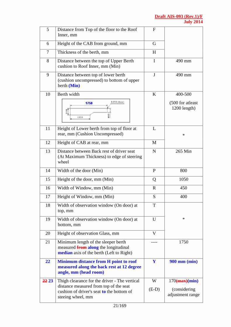
21/169
5 Distance from Top of the floor to the Roof
Inner, mm
F
6 Height of the CAB from ground, mm G
7 Thickness of the berth, mm H
8 Distance between the top of Upper Berth
cushion to Roof Inner, mm (Min)
I 490 mm
9 Distance between top of lower berth
(cushion uncompressed) to bottom of upper
berth (Min)
J 490 mm
10 Berth width K 400-500
(500 for atleast
1200 length)
11 Height of Lower berth from top of floor at
rear, mm (Cushion Uncompressed)
L
*
12 Height of CAB at rear, mm M
13 Distance between Back rest of driver seat
(At Maximum Thickness) to edge of steering
wheel
N 265 Min
14 Width of the door (Min) P 800
15 Height of the door, mm (Min) Q 1050
16 Width of Window, mm (Min) R 450
17 Height of Window, mm (Min) S 400
18 Width of observation window (On door) at
top, mm
T
* 19 Width of observation window (On door) at
bottom, mm
U
20 Height of observation Glass, mm V
21 Minimum length of the sleeper berth
measured from along the longitudinal
median axis of the berth (Left to Right)
---- 1750
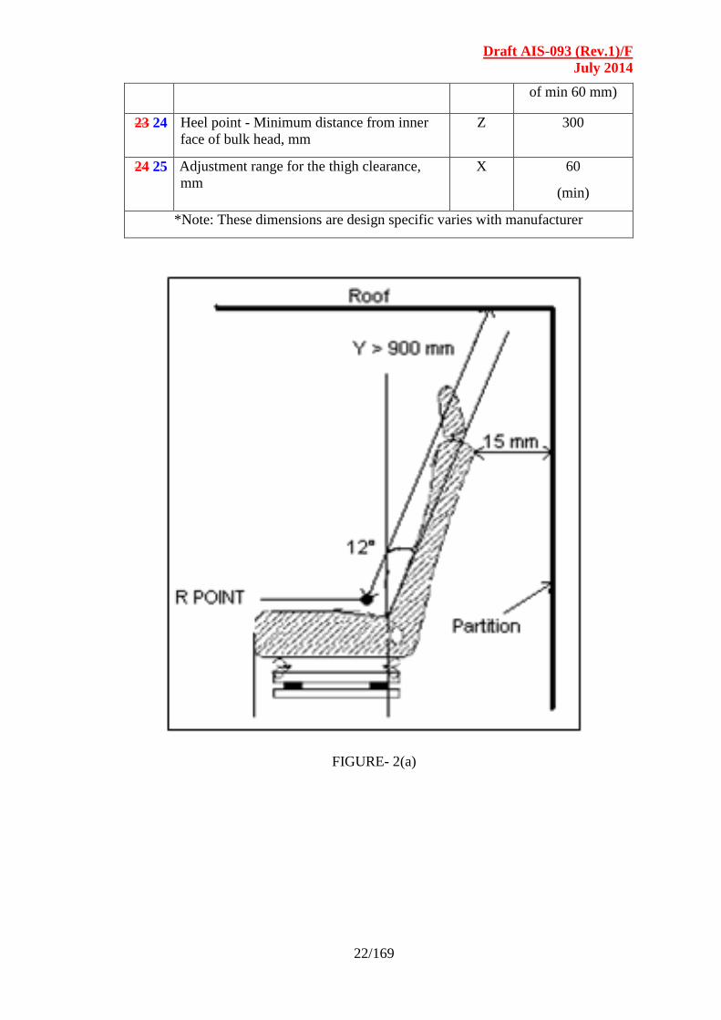
22 Minimum distance from H point to roof
measured along the back rest at 12 degree
angle, mm (head room)
Y 900 mm (min)
22 23 Thigh clearance for the driver - The vertical
distance measured from top of the seat
cushion of driver's seat to the bottom of
steeing wheel, mm
W
(E-D)
170(max)(min)
(considering
adjustment range
Draft AIS-093 (Rev.1)/F
July 2014
22/169
of min 60 mm)
23 24 Heel point - Minimum distance from inner
face of bulk head, mm
Z 300
24 25 Adjustment range for the thigh clearance,
mm
X 60
(min)
*Note: These dimensions are design specific varies with manufacturer
FIGURE- 2(a)
Draft AIS-093 (Rev.1)/F
July 2014
23/169
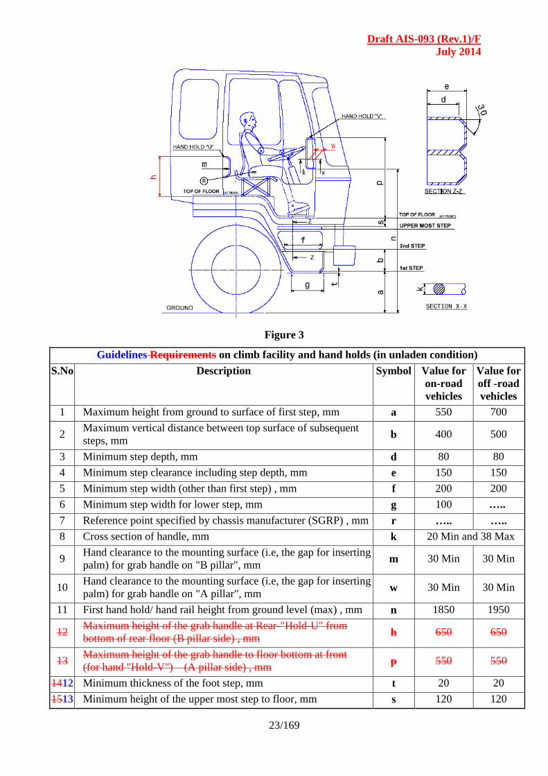
Figure 3
Guidelines Requirements on climb facility and hand holds (in unladen condition)
S.No Description Symbol Value for
on-road
vehicles
Value for
off -road
vehicles
1 Maximum height from ground to surface of first step, mm a 550 700
2 Maximum vertical distance between top surface of subsequent
steps, mm b 400 500
3 Minimum step depth, mm d 80 80
4 Minimum step clearance including step depth, mm e 150 150
5 Minimum step width (other than first step) , mm f 200 200
6 Minimum step width for lower step, mm g 100 …..
7 Reference point specified by chassis manufacturer (SGRP) , mm r ….. …..
8 Cross section of handle, mm k 20 Min and 38 Max
9 Hand clearance to the mounting surface (i.e, the gap for inserting
palm) for grab handle on "B pillar", mm m 30 Min 30 Min
10 Hand clearance to the mounting surface (i.e, the gap for inserting
palm) for grab handle on "A pillar", mm w 30 Min 30 Min
11 First hand hold/ hand rail height from ground level (max) , mm n 1850 1950
12 Maximum height of the grab handle at Rear-"Hold-U" from
bottom of rear floor (B pillar side) , mm h 650 650
13 Maximum height of the grab handle to floor bottom at front
(for hand "Hold-V") (A pillar side) , mm p 550 550
1412 Minimum thickness of the foot step, mm t 20 20
1513 Minimum height of the upper most step to floor, mm s 120 120
Draft AIS-093 (Rev.1)/F
July 2014
24 / 169
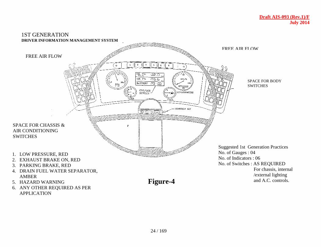
1ST GENERATION DRIVER INFORMATION MANAGEMENT SYSTEM
FREE AIR FLOW
FREE AIR FLOW
SPACE FOR CHASSIS &
AIR CONDITIONING
SWITCHES
SPACE FOR BODY
SWITCHES
1. LOW PRESSURE, RED
2. EXHAUST BRAKE ON, RED
3. PARKING BRAKE, RED
4. DRAIN FUEL WATER SEPARATOR,
AMBER
5. HAZARD WARNING
6. ANY OTHER REQUIRED AS PER
APPLICATION
Suggested 1st Generation Practices
No. of Gauges : 04
No. of Indicators : 06
No. of Switches : AS REQUIRED
For chassis, internal
/external lighting
and A.C. controls.
Figure-4

Draft AIS-093 (Rev.1)/F
July 2014
25/156
SECTION - 3.0
TRUCK LOAD BODY –
GENERAL, TECHNICAL AND SAFETY REQUIREMENTS
LIST OF CONTENTS
3.1 Categorisation of Truck Load Bodies
3.2 General Requirements
3.2.1 Overall Dimensions
3.2.2 Cab and Body gap
3.2.3 Stowage Space/ Luggage Carrier
3.2.4 Mudguards / Spray Suppression Devices
3.2.5 Rope Hooks and other Provisions
3.3 Technical Requirements
3.3.1 Truck Body working Stability
3.3.2 Mounting of the Body or Load Platform of Commercial
Vehicles
3.3.3 Body Construction requirements
3.4 Safety Requirements
3.4.1
Protection of the Occupants of Goods-carrying Power-driven
Vehicles
against the Shifting of Loads
3.4.2 Securing the Load on the Load body
3.4.3 External Projection
3.4.4 Lighting and Signaling devices
3.4.5 Retro-Reflective Markings for Heavy and Long Vehicles
3.4.6 Lateral Protection
3.4.7 Rear Under run Protection
3.4.8 Modification of Chassis and / or Chassis related Components
3.4.9 Corrosion Protection
3.4.10 Closed Type Bodies
Draft AIS-093 (Rev.1)/F
July 2014
26 / 169
3.1 Categorization of truck load bodies :
The trucks are categorized on the basis of design namely rigid axle
vehicles and tractor trailer combination. Trucks are further sub-
categorized on the basis of truck body construction like the following.
HSD – High Side Deck body
FSD – Fixed Side Deck or Half body
DSD – Drop Side Deck body
FB – Flat Bed or Fully open body
CLB – Closed Body
ALC – Aluminium Container
STC – Steel container
SPB – Special Purpose Body including tippers & dump trucks
3.2 General requirements :
3.2.1 Overall dimensions : The overall dimensions of the load body shall
comply with the provisions laid down in Rule 93 of the Central Motor
Vehicle Rules, 1989 as amended from time to time.
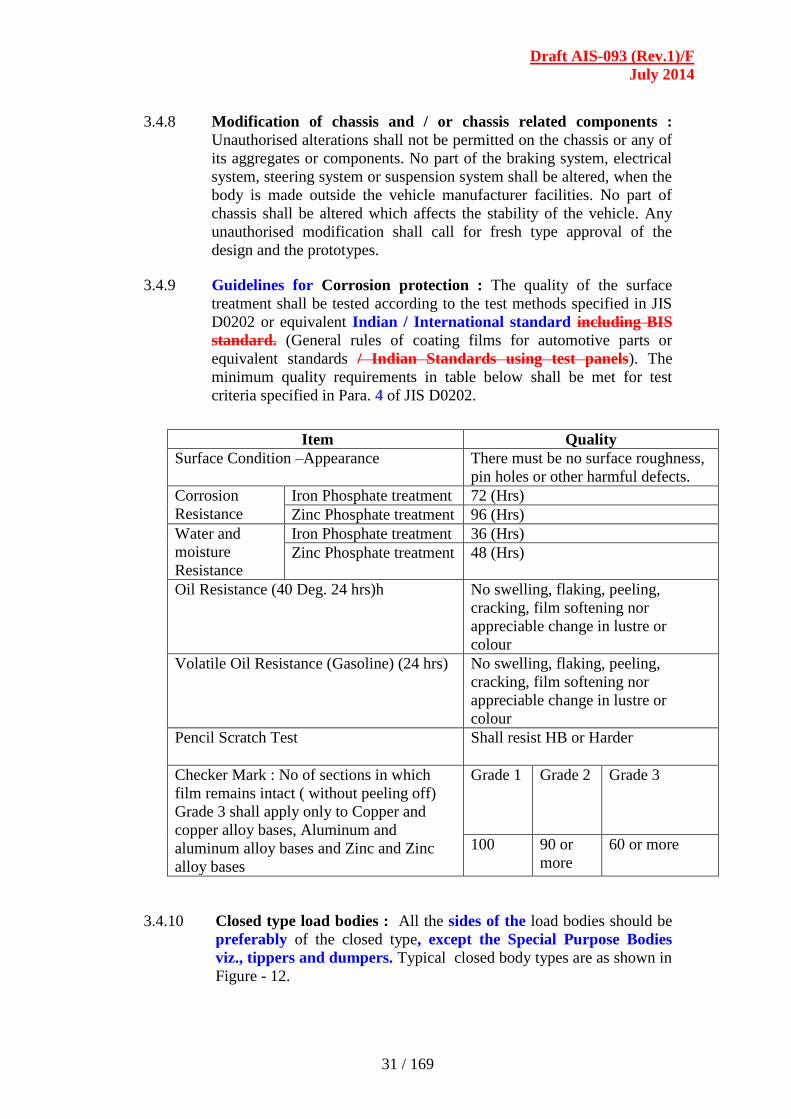
3.2.2 Cab and body gap : Clearances / gaps as recommended by vehicle
manufacturer should be ensured in respect of tyre, wheel arch, fuel / oil
checking and filling, cab (where applicable). In the case of separate cab
and load body, the body shall be separated from cab by at-least 50mm
behind as shown in Figure -4. The gap may be covered with gap seal
for better aerodynamics.
3.2.3 Stowage space / luggage carrier: Storage Stowage space for keeping
utility items like tarpaulin, manila rope, assorted tools etc. may be
provided in any part of the vehicle or load body. If the same is provided
over the load body, it shall meet the following requirements:
- Uniformly distributed static load of 150 kg/m2
- Inertia forces equivalent of 2.5 g.
- Shear force equivalent to 1.5g.
Further, the maximum load capacity of such a stowage space shall be
specified on a plate fitted outside the stowage space.
3.2.4 Mudguards / Spray suppression devices : The tyres of motor vehicles
shall be enveloped with effective mudguards. The mudguards may be
mounted on body floor or any part of the chassis frame. Non-rigid flap
(metallic or non-metallic) shall be provided at rear of mudguards to
prevent splashing of water, dust or muck over the vehicles coming from
behind. In addition, the vehicles shall be fitted with spray suppression
devices in accordance with AIS-013, relevant for the categories of
vehicles specified therein.
3.2.5 Rope hooks and other provisions : The load bodies shall be so
constructed to allow use of covers, wherever required. Rope hooks or
any such feature may be provided on sides, front, rear or base of the
load body to facilitate spreading and fastening of covers over the body.
Sufficient space must be provided on sides of body to depict vehicle
related details as specified by National or State Transport Rules.
Draft AIS-093 (Rev.1)/F
July 2014
27 / 169
3.3 Technical requirements :
3.3.1 Working stability : The vehicles meant for carrying dangerous and / or
hazardous goods shall meet the working stability requirements stated in
Section -8 of this Code.
3.3.2 Mounting of the body or load platform of commercial vehicles :
3.3.2.1 The mounting arrangement for load body shall ensure adequate rigidity
of body with the chassis.
3.3.2.2 The mountings shall ensure adequate resistance against lateral /
transverse movement of load body in case of braking or sudden
acceleration or cornering or while driving on slopes. The
recommendations of the OEM’s shall be taken as guidelines.
3.3.2.3 For mountings, use shall be made of round holes and suitable bolts with
the least possible play, at least at the foremost and rearmost attachment
points.
3.3.2.4 Suitable compressible packing (such as rubberised ballatta duck, or
wood) may be used between the chassis and body frame. Thickness of
such packing shall be selected to ensure uniform load distribution over
chassis frame even in case of minor waviness or twist in the chassis
frame / sub-frame.
3.3.2.5 The sub-frame shall be mounted on chassis by means of attachment
plates or out-rigger brackets or directly on chassis to prevent
longitudinal movement of load body in case of braking and sudden
acceleration as shown in Figure – 1. Wherever, the U-bolts are used for
clamping (in addition to positive mountings as stated above), they shall
be used in conjunction with stiffeners to prevent chassis frame from
buckling, as shown in Figure – 2.
3.3.2.6 In case of load bodies not made by OEM or as per OEM designs, the
mounting arrangement for the load body or platforms shall be as per
recommendations provided by the vehicle manufacturers. Details of
recommended practices for load body mounting including list of
approved parts to be provided by vehicle manufacturer. OE developed
and type approved designs may be used by local body builders.
3.3.3 Body construction requirements :
3.3.3.1 In constructing the body or load platform, all practicable steps shall be
taken to keep the centre of gravity of the vehicle as low as possible.
3.3.3.2 The construction of the body or load platform shall be such as not to
impair the soundness and functioning of the wiring and braking circuits.
3.3.3.3 The load body shall be constructed over a sub-frame to distribute the
load evenly on the chassis frame and also to create gap between body
and tyre / chassis for wheel articulation.
3.3.3.4 The material used for sub-frame construction shall be steel or
aluminum alloy or any composite material with adequate strength to
bear impact loads.
Draft AIS-093 (Rev.1)/F
July 2014
28 / 169
3.3.3.5 The sub-frame shall be angled, curved or forked in the front as shown
in Figure-5.
3.3.3.6 The sub-frame shall be mounted on chassis by means of attachment
plates or out-rigger brackets or directly on chassis to prevent
longitudinal movement of load body in case of braking and sudden
acceleration. The number and size of hardware used for attaching shall
be determined by the payload carried on the vehicle. Self-locking or
“Anti-vibration” hardware shall be used for fastening. Some other
typical arrangements for mounting the sub-frame and the
recommendatory guidelines are as shown in Figure - 6 to Figure -11.
3.3.3.7 The floor, head board (also called crash guard or front wall) and side
walls are the main load bearing elements of the body. The floor shall be
rigidly supported on the sub-frame. The section of floor and floor
supports in the sub-frame shall be pitched / spaced to achieve
distributed loads even in case of concentrated loads such as steel coils
or fork lifts etc.
3.3.3.8 The side walls and crash guard shall be constructed to bear a part of
load carried on the vehicle in case of braking, turning, travel on slopes
etc. as given below, which can also be proved by FEM analysis.
Side walls : 30 % of rated pay load carried
Crash guard or head board : 100 % 40% of rated pay load carried,
the maximum however being 5000 kgf
Rear wall or tail gate : 30% 25% of rated pay load carried
3.3.3.9 Where the cab and bodywork are integral, account shall be taken of the
flexibility of the cab mounting.
3.3.3.10 In the case of tank-vehicles, where outrigger brackets are used to fasten
the tank to the chassis of the vehicle, the vertical face of the brackets
shall not be less in height than the depth of the chassis frame to which
they are attached.
3.3.3.11 In the case of tipping vehicles, where there is no supplementary under-
frame, to distribute the load, the pivot brackets for rearward tipping
bodies shall be located as near as possible to the rear spring brackets to
minimize additional bending stresses on the chassis frame during
tipping.
3.3.3.12 In the case of bodies tipping rearwards only, guide plates shall be
provided to control the lateral movement of the body when lowered
onto the chassis frame.
3.3.3.13 In the case of tipping bodies, steps shall be taken to prevent excessive
noise caused by the bodywork of the vehicle when it is unladen.
3.4 Safety requirements :
3.4.1 Protection of the occupants of goods-carrying power-driven
vehicles against the shifting of loads :
Draft AIS-093 (Rev.1)/F
July 2014
29 / 169
3.4.1.1 The equipment of vehicles shall be in conformity with provisions
calculated to reduce the risks run by the driver and the other occupants
of goods-carrying vehicles in the event of a forward shift of the load on
sudden braking.
3.4.1.2 The occupants of such a vehicle shall be protected by a screen or
headboard capable of withstanding without breaking, a uniformly
distributed static force of 200 kgf per ton of the vehicle's permissible
useful load. This load shall be applied by means of a rigid barrier
perpendicular to the longitudinal median axis of the vehicle, covering at
least the whole of the cab rear wall situated above the chassis frame,
and moving parallel to that axis. This shall be in accordance with the
requirements specified in AIS-029.
3.4.1.3 This protective screen or headboard may be detachable. It must meet
the following requirements:
3.4.1.3.1 It’s width (measured at right angles to the longitudinal median axis of
the vehicle) must be at least equal to the width of the space provided for
the occupants and where there is a separate cab, at least equal to the
width of the cab.
3.4.1.3.2 In height, it must match at least 800 mm for N3 category vehicles
and may be at least 800 mm for N2 category vehicles.
3.4.1.3.3 It must be secured directly to the chassis or to the front of the loading
platform.
3.4.1.3.4 If it is secured to the loading platform or, where appropriate, to the
body, the anchorage of that platform to the chassis must be capable of
withstanding the thrust transmitted.
3.4.1.3.5 In cases where the cab is integral with the body, the protective screen or
headboard may be secured to, or form part of, the body structure.
3.4.1.3.6 Where a power-driven vehicle or a semi-trailer is designed to carry
beams, pipes, girders, sheet metal or similar loads, the protective screen
or headboard must have a resistance at least equal to that of steel plate
not less than 3 mm thick.
3.4.1.3.7 Where a vehicle is equipped with a trestle or bolster behind the cab for
the purpose of supporting long loads, such as steel girders or
telegraphic poles, the trestle or bolster must be capable of withstanding
the combined effect of two forces, each of 600 daN per ton of
permissible load, acting forwards and downwards on the top of the
trestle.
3.4.1.3.8 This rule shall not apply to tank-lorries and special-purpose vehicles for
the carriage of containers, or to special-purpose vehicles for the
carriage of indivisible objects, where the latter vehicles and their
operation are subject to special regulations
Draft AIS-093 (Rev.1)/F
July 2014
30 / 169
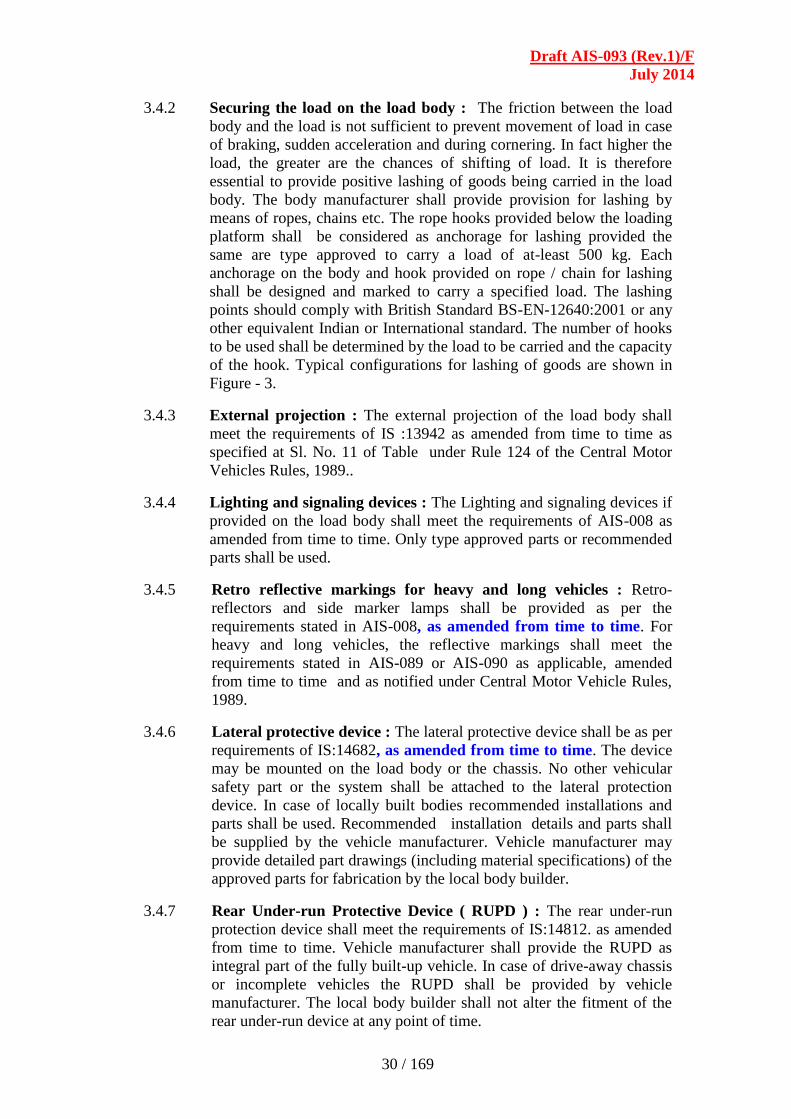
3.4.2 Securing the load on the load body : The friction between the load
body and the load is not sufficient to prevent movement of load in case
of braking, sudden acceleration and during cornering. In fact higher the
load, the greater are the chances of shifting of load. It is therefore
essential to provide positive lashing of goods being carried in the load
body. The body manufacturer shall provide provision for lashing by
means of ropes, chains etc. The rope hooks provided below the loading
platform shall be considered as anchorage for lashing provided the
same are type approved to carry a load of at-least 500 kg. Each
anchorage on the body and hook provided on rope / chain for lashing
shall be designed and marked to carry a specified load. The lashing
points should comply with British Standard BS-EN-12640:2001 or any
other equivalent Indian or International standard. The number of hooks
to be used shall be determined by the load to be carried and the capacity
of the hook. Typical configurations for lashing of goods are shown in
Figure - 3.
3.4.3 External projection : The external projection of the load body shall
meet the requirements of IS :13942 as amended from time to time as
specified at Sl. No. 11 of Table under Rule 124 of the Central Motor
Vehicles Rules, 1989.. 3.4.4 Lighting and signaling devices : The Lighting and signaling devices if
provided on the load body shall meet the requirements of AIS-008 as
amended from time to time. Only type approved parts or recommended
parts shall be used.
3.4.5 Retro reflective markings for heavy and long vehicles : Retro-
reflectors and side marker lamps shall be provided as per the
requirements stated in AIS-008, as amended from time to time. For
heavy and long vehicles, the reflective markings shall meet the
requirements stated in AIS-089 or AIS-090 as applicable, amended
from time to time and as notified under Central Motor Vehicle Rules,
1989.
3.4.6 Lateral protective device : The lateral protective device shall be as per
requirements of IS:14682, as amended from time to time. The device
may be mounted on the load body or the chassis. No other vehicular
safety part or the system shall be attached to the lateral protection
device. In case of locally built bodies recommended installations and
parts shall be used. Recommended installation details and parts shall
be supplied by the vehicle manufacturer. Vehicle manufacturer may
provide detailed part drawings (including material specifications) of the
approved parts for fabrication by the local body builder.
3.4.7 Rear Under-run Protective Device ( RUPD ) : The rear under-run
protection device shall meet the requirements of IS:14812. as amended
from time to time. Vehicle manufacturer shall provide the RUPD as
integral part of the fully built-up vehicle. In case of drive-away chassis
or incomplete vehicles the RUPD shall be provided by vehicle
manufacturer. The local body builder shall not alter the fitment of the
rear under-run device at any point of time.
Draft AIS-093 (Rev.1)/F
July 2014
31 / 169
3.4.8 Modification of chassis and / or chassis related components :
Unauthorised alterations shall not be permitted on the chassis or any of
its aggregates or components. No part of the braking system, electrical
system, steering system or suspension system shall be altered, when the
body is made outside the vehicle manufacturer facilities. No part of
chassis shall be altered which affects the stability of the vehicle. Any
unauthorised modification shall call for fresh type approval of the
design and the prototypes.
3.4.9 Guidelines for Corrosion protection : The quality of the surface
treatment shall be tested according to the test methods specified in JIS
D0202 or equivalent Indian / International standard including BIS
standard. (General rules of coating films for automotive parts or
equivalent standards / Indian Standards using test panels). The
minimum quality requirements in table below shall be met for test
criteria specified in Para. 4 of JIS D0202.
Item Quality
Surface Condition –Appearance There must be no surface roughness,
pin holes or other harmful defects.
Corrosion
Resistance
Iron Phosphate treatment 72 (Hrs)
Zinc Phosphate treatment 96 (Hrs)
Water and
moisture
Resistance
Iron Phosphate treatment 36 (Hrs)
Zinc Phosphate treatment 48 (Hrs)
Oil Resistance (40 Deg. 24 hrs)h No swelling, flaking, peeling,
cracking, film softening nor
appreciable change in lustre or
colour
Volatile Oil Resistance (Gasoline) (24 hrs) No swelling, flaking, peeling,
cracking, film softening nor
appreciable change in lustre or
colour
Pencil Scratch Test Shall resist HB or Harder
Checker Mark : No of sections in which
film remains intact ( without peeling off)
Grade 3 shall apply only to Copper and
copper alloy bases, Aluminum and
aluminum alloy bases and Zinc and Zinc
alloy bases
Grade 1 Grade 2 Grade 3
100 90 or
more
60 or more
3.4.10 Closed type load bodies : All the sides of the load bodies should be
preferably of the closed type, except the Special Purpose Bodies
viz., tippers and dumpers. Typical closed body types are as shown in
Figure - 12.

Draft AIS-093 (Rev.1)/F
July 2014
32 / 169
Figure -1
Chassis and Body Frame Mounting
Figure - 2
Typical Load Body Mounting using U-Bolts
Draft AIS-093 (Rev.1)/F
July 2014
33 / 169
Figure - 3
Typical Hook Configuration for Lashing of Goods
Figure - 4
Cabin and Body Gap

Draft AIS-093 (Rev.1)/F
July 2014
34 / 169
Figure - 5
Front End Configuration of Sub-Frame
Draft AIS-093 (Rev.1)/F
July 2014
35 / 169
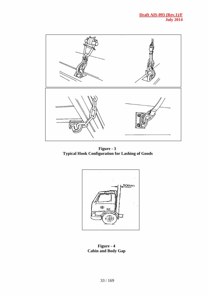
Figure - 6
Mounting of Sub-frame
Draft AIS-093 (Rev.1)/F
July 2014
36 / 169
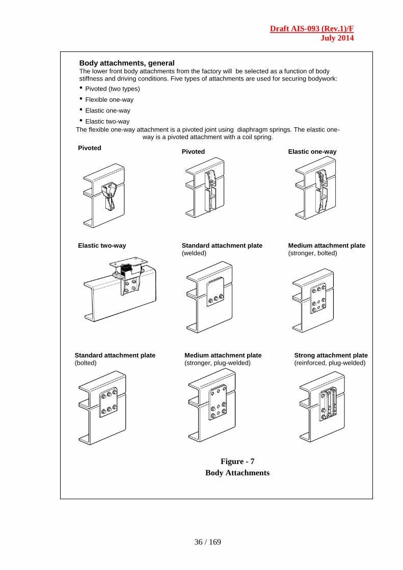
Body attachments, general The lower front body attachments from the factory will be selected as a function of body stiffness and driving conditions. Five types of attachments are used for securing bodywork:
• Pivoted (two types)
• Flexible one-way
• Elastic one-way
• Elastic two-way
The flexible one-way attachment is a pivoted joint using diaphragm springs. The elastic one-way is a pivoted attachment with a coil spring.
Pivoted
Pivoted
Elastic one-way
Elastic two-way
Standard attachment plate
(welded)
Standard attachment plate
(bolted)
Medium attachment plate
(stronger, plug-welded)
Medium attachment plate
(stronger, bolted)
Strong attachment plate
(reinforced, plug-welded)
Figure - 7
Body Attachments
Draft AIS-093 (Rev.1)/F
July 2014
37 / 169
Distance between attachment unit Below is the recommended distance between hole groups, depending on the vehicle’s attachment unit.
Upper part of attachment The upper part of the pivoted attachments should be fitted to the sub frame so that the lower edge overlaps the chassis frame by:
• 30±1 mm for frames with a height of 300 mm (see illustration).
• 23±1 mm for frames with a height of 266 mm.
Figure - 8
Distance between Attachment Units
2–hole groups 400–600 mm
4/6–hole groups 800–1000 mm
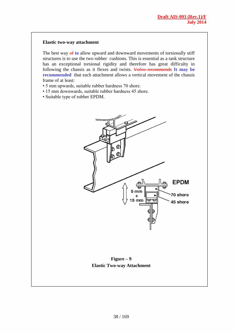
Draft AIS-093 (Rev.1)/F
July 2014
38 / 169
Elastic two-way attachment
The best way of to allow upward and downward movements of torsionally stiff
structures is to use the two rubber cushions. This is essential as a tank structure
has an exceptional torsional rigidity and therefore has great difficulty in
following the chassis as it flexes and twists. Volvo recommends It may be
recommended that each attachment allows a vertical movement of the chassis
frame of at least:
• 5 mm upwards, suitable rubber hardness 70 shore.
• 15 mm downwards, suitable rubber hardness 45 shore.
• Suitable type of rubber EPDM.
Figure – 9
Elastic Two-way Attachment

Draft AIS-093 (Rev.1)/F
July 2014
39 / 169
Clamps Clamps can place high bending forces in the chassis
flanges. Spacers (A) must always be fitted between the
chassis/sub/helper-frame flanges, if clamps are used.
Recommended attachments
Bodywork must be secured so that the complete vehicle:
• has good driving characteristics.
• has sufficient stability and strength.
• is capable of carrying out the transport work safely. Twisting and sideways movements
are more common behind the cab but diminish the further back along the truck one
goes. In addition, lengthways and sideways forces must be absorbed by the attachments.
Along the front part of the sub frame / helper-frame, the attachments should be pivoted
as much as possible so as to allow maximum chassis movement in relation to the
road/ground. For the most rigid bodywork, flexible two-way attachments are used along
the whole length of the frame. The bodywork must have the freedom to move in
relation to the chassis frame. The more rigid the bodywork, the greater the movement in
the attachment is required. With the exception of the most rigid bodywork,
attachment plates are used along the rear section of the sub frame/helper-frame.
Figure - 10
Clamps and Recommended Attachments

Draft AIS-093 (Rev.1)/F
July 2014
40 / 169
RC-SMOOT = Road conditions, smooth conditions
RC-ROUGH/VROUG = Road conditions, rough/very rough conditions
Note: For some of the positions shown in the table above, a choice of attachments can be made.
This choice is dependant on the type of bodywork and bogie used.
Note: The above table specifies the minimum requirements. More flexible anchorages or
stronger plates can also be selected.
Figure - 11
Body Work and Recommended Attachments
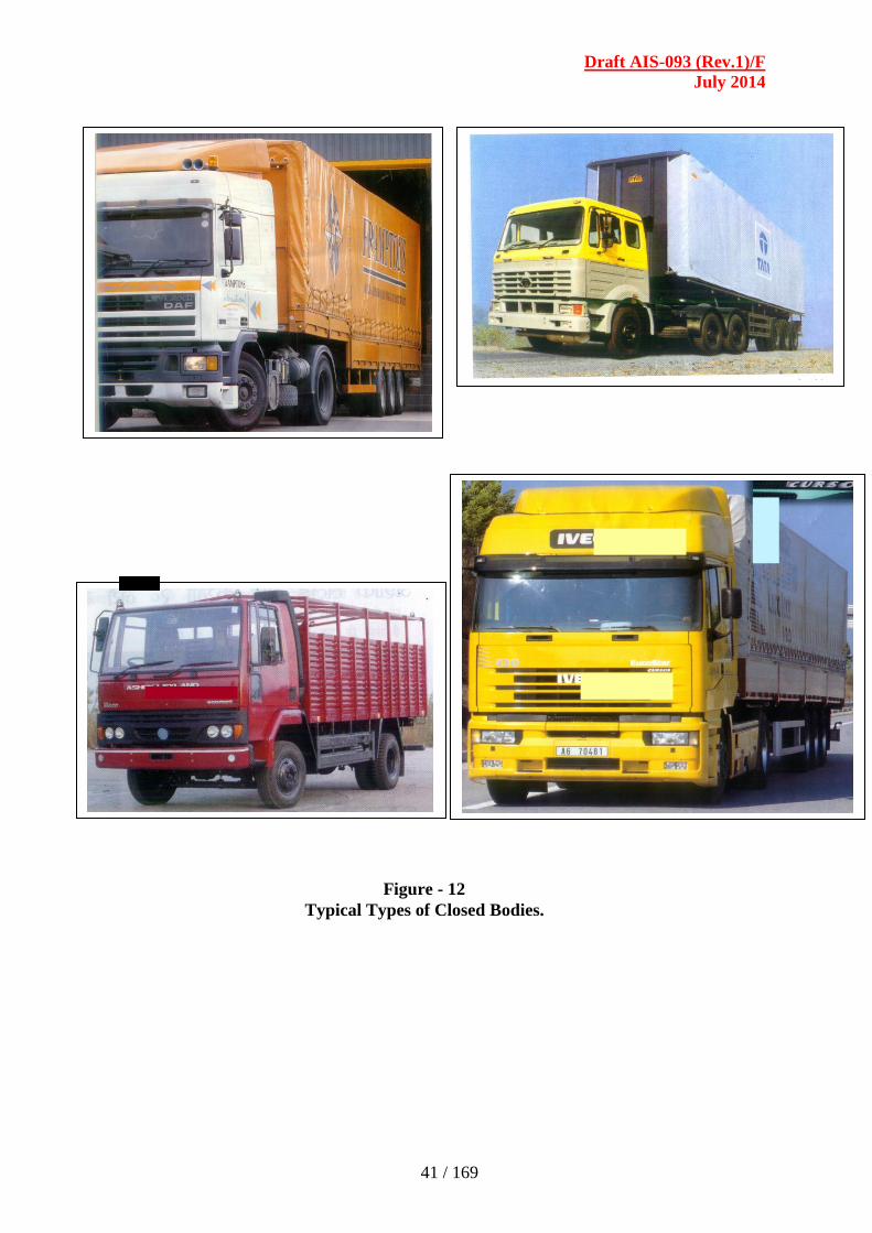
Draft AIS-093 (Rev.1)/F
July 2014
41 / 169
Figure - 12
Typical Types of Closed Bodies.

Draft AIS-093 (Rev.1)/F
July 2014
42 / 169
SECTION - 4.0
REQUIREMENTS OF LIGHTING, ILLUMINATION,
ELECTRICAL EQUIPMENT AND WIRING
LIST OF CONTENTS
4.1 Lighting, Signalling and Indicating Systems
4.1.1 External
4.1.2 Internal
4.1.3 Position of illumination devices
4.1.4 Type of Bulbs for lamp Assemblies
4.2 Driver Cab lighting
4.3 Electrical Equipment and Wiring
4.3.1 Electrical cables
4.3.2 Fuse
4.3.3 Terminals, Connectors and Elements
4.4 Safety requirements
4.5 Batteries
4.6 Type Approval
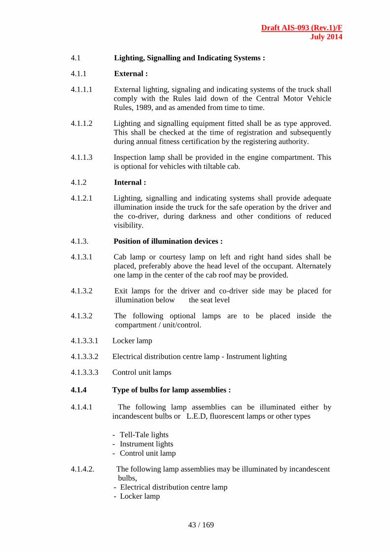
Draft AIS-093 (Rev.1)/F
July 2014
43 / 169
4.1 Lighting, Signalling and Indicating Systems :
4.1.1 External :
4.1.1.1 External lighting, signaling and indicating systems of the truck shall
comply with the Rules laid down of the Central Motor Vehicle
Rules, 1989, and as amended from time to time.
4.1.1.2 Lighting and signalling equipment fitted shall be as type approved.
This shall be checked at the time of registration and subsequently
during annual fitness certification by the registering authority.
4.1.1.3 Inspection lamp shall be provided in the engine compartment. This
is optional for vehicles with tiltable cab.
4.1.2 Internal :
4.1.2.1 Lighting, signalling and indicating systems shall provide adequate
illumination inside the truck for the safe operation by the driver and
the co-driver, during darkness and other conditions of reduced
visibility.
4.1.3. Position of illumination devices :
4.1.3.1 Cab lamp or courtesy lamp on left and right hand sides shall be
placed, preferably above the head level of the occupant. Alternately
one lamp in the center of the cab roof may be provided.
4.1.3.2 Exit lamps for the driver and co-driver side may be placed for
illumination below the seat level
4.1.3.2 The following optional lamps are to be placed inside the
compartment / unit/control.
4.1.3.3.1 Locker lamp
4.1.3.3.2 Electrical distribution centre lamp - Instrument lighting
4.1.3.3.3 Control unit lamps
4.1.4 Type of bulbs for lamp assemblies :
4.1.4.1 The following lamp assemblies can be illuminated either by
incandescent bulbs or L.E.D, fluorescent lamps or other types
- Tell-Tale lights
- Instrument lights
- Control unit lamp
4.1.4.2. The following lamp assemblies may be illuminated by incandescent
bulbs,
- Electrical distribution centre lamp
- Locker lamp

Draft AIS-093 (Rev.1)/F
July 2014
44 / 169
4.1.4.3. The following lamp assemblies may be illuminated by incandescent
bulbs or fluorescent bulbs,
- Entrance lamps
- Cab lamp or courtesy lamp
- Passenger area lamp
4.1.4.4. Photometric Requirements
4.1.4.4.1. Lighting requirements of the lighting, signalling and indicating
systems for the following sub groups,
- Dash Board Tell-Tale Lighting/Control Lighting
- Driver Cab Lighting
- Other Area Lighting
4.1.4.4.2. Dash Board Tell -Tale Lighting/Control Lighting
4.1.4.4.2.1. Lamps falling in this category -
- Instrument lighting
- Tell-Tale lighting
- Control unit lamps
4.1.4.4.2.2 The illumination by lighting devices lighting up dash board
instruments, tell tales and controls shall be discreet and shall not
disturb the driver when driving in the dark.
4.1.4.4.2.3. The regulation of the intensity of illumination of instrument lighting
shall be optional. If available, the strength of the instrument lighting
shall be capable of regulation through a rheostat or any other
suitable means.
4.2 Driver cab lighting
4.2.1 The following lamps fall in this category,
- Cab lamp or courtesy lamp
- Locker lamp
- Electrical distribution lamp
4.2.2 The illumination by lighting devices lighting up the cab interior
should be sufficient enough to clearly distinguishing component
part of the cab. Driver should be in a position to read signage
written on the walls, door of the cab. He should also be in position
to read any instructions printed on paper
4.3. Electrical Equipment and Wiring :
4.3.1. Electrical cables :
4.3.1.1. All cables used shall be compliant with
BIS/SAE/JIS/DIN/JASO/ISO or any equivalent standards
marked. Copper conductors with fire retardant PVC insulation and
able to withstand working temperatures.

Draft AIS-093 (Rev.1)/F
July 2014
45 / 169
4.3.1.2. All the cables shall be ducted and secured at suitable places in such a
manner that during normal use of vehicle the cables are not
subjected to any tension, stretching, nicking, cutting, abrasion, or
chaffing. Some examples are as given in Figure 1 and Figure 2.
4.3.2. Fuse :
4.3.2.1. Every electrical circuit shall be provided with fuse designed for the
circuit. In case of multiple circuits a common fuse may be permitted.
4.3.3. Terminals, Connectors and Elements :
4.3.3.1. End terminations: All the ends shall be suitably crimped with lugs /
soldered or fixed so as to withstand vehicle vibrations. The
interconnection shall be through couplers / junction boxes/ terminal
blocks. Some of the correct and incorrect methods of clamping are
as indicated in Figures - 1, 2 and 3.
4.3.3.2. Weatherproof connectors shall be used for external areas to avoid
water/ moisture ingress during use.
4.3.3.3. All wiring must be anchored to the chassis at intervals of not
more than 600 mm along its length. ( Refer Figures 4, 5 and 7)
4.3.3.4. All wiring must be insulated at joints and also wiring must be located
in such a position that it can neither become overheated nor contact
moving parts. Some example of wiring on the cab and body of the
vehicle areas indicated in Figures 4 to 7.
4.3.3.5 In case of trailers and towing vehicles the 7-pin connector, 12- pin
connector or 15-pin connector as indicated in Figures - 8, 9, 10 &
11, shall be used. Guidelines for electrical connections between
towing vehicles and trailers may be drawn from IS : 13460, IS :
13461, IS : 13491 and IS : 13499.
4.4. Safety requirements :
4.4.1. Use of relays and other electrical elements shall be adopted where
the current rating of the switches is not adequate.
4.4.2. The additional circuits shall not draw current more than specified by
the manufacturer.
4.4.3. Where the voltage exceeds 100 Volts RMS (Root Mean Square)
in one or more electrical circuit, a manually operated isolation
switch, which is capable of disconnecting the circuit(s) from the
main electrical supply, shall be provided and shall be located inside
the vehicle in a location easily accessible to the driver.
Alternatively battery cut off switch may be provided.
4.4.4. The electrical circuit provided by the vehicle manufacturer which
are type approved shall not be modified. However, additional
circuits may be made with the concurrence of OEM or as per the
recommended practice of OEM. Provisions for tapping / socket /
connector be provided for enabling use of external inspection lamp.
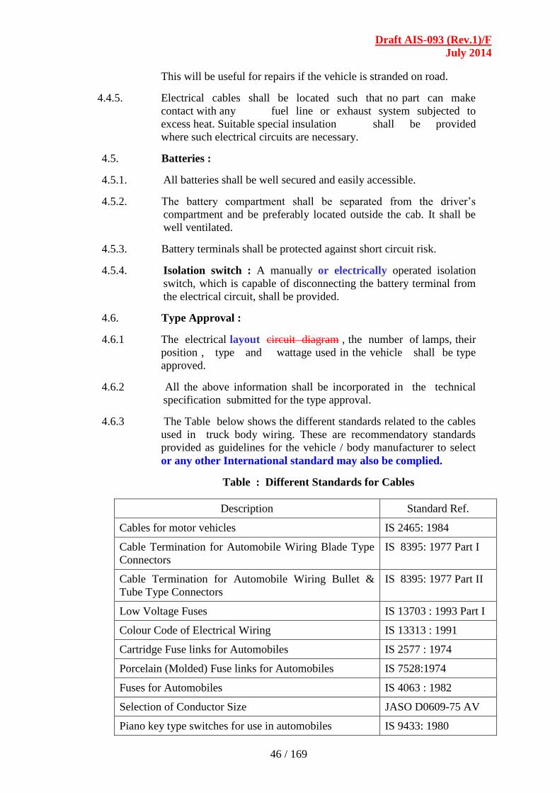
Draft AIS-093 (Rev.1)/F
July 2014
46 / 169
This will be useful for repairs if the vehicle is stranded on road.
4.4.5. Electrical cables shall be located such that no part can make
contact with any fuel line or exhaust system subjected to
excess heat. Suitable special insulation shall be provided
where such electrical circuits are necessary.
4.5. Batteries :
4.5.1. All batteries shall be well secured and easily accessible.
4.5.2. The battery compartment shall be separated from the driver’s
compartment and be preferably located outside the cab. It shall be
well ventilated.
4.5.3. Battery terminals shall be protected against short circuit risk.
4.5.4. Isolation switch : A manually or electrically operated isolation
switch, which is capable of disconnecting the battery terminal from
the electrical circuit, shall be provided.
4.6. Type Approval :
4.6.1 The electrical layout circuit diagram , the number of lamps, their
position , type and wattage used in the vehicle shall be type
approved.
4.6.2 All the above information shall be incorporated in the technical
specification submitted for the type approval.
4.6.3 The Table below shows the different standards related to the cables
used in truck body wiring. These are recommendatory standards
provided as guidelines for the vehicle / body manufacturer to select
or any other International standard may also be complied.
Table : Different Standards for Cables
Description Standard Ref.
Cables for motor vehicles IS 2465: 1984
Cable Termination for Automobile Wiring Blade Type
Connectors
IS 8395: 1977 Part I
Cable Termination for Automobile Wiring Bullet &
Tube Type Connectors
IS 8395: 1977 Part II
Low Voltage Fuses IS 13703 : 1993 Part I
Colour Code of Electrical Wiring IS 13313 : 1991
Cartridge Fuse links for Automobiles IS 2577 : 1974
Porcelain (Molded) Fuse links for Automobiles IS 7528:1974
Fuses for Automobiles IS 4063 : 1982
Selection of Conductor Size JASO D0609-75 AV
Piano key type switches for use in automobiles IS 9433: 1980
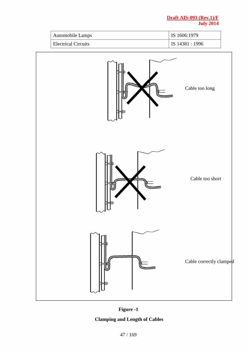
Draft AIS-093 (Rev.1)/F
July 2014
47 / 169
Automobile Lamps IS 1606:1979
Electrical Circuits IS 14381 : 1996
Figure -1
Clamping and Length of Cables
Cable too long
Cable too short
Cable correctly clamped

Draft AIS-093 (Rev.1)/F
July 2014
48 / 169
Figure 2
Clamping and joints

Draft AIS-093 (Rev.1)/F
July 2014
49 / 169
Clamping of cables with a corrugated sheath
• Clamping of cables with a corrugated sheath, the so-called ”Schlemmer hoses” shall be
done as in the illustrations below
Figure 3
Clamping with Corrugated Sheath

Draft AIS-093 (Rev.1)/F
July 2014
50 / 169
Figure -4
Wiring on the Chassis
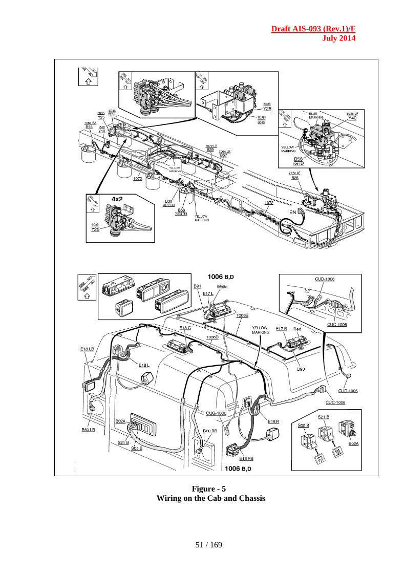
Draft AIS-093 (Rev.1)/F
July 2014
51 / 169
Figure - 5
Wiring on the Cab and Chassis

Draft AIS-093 (Rev.1)/F
July 2014
52 / 169
Figure - 6
Wiring on the Cab

Draft AIS-093 (Rev.1)/F
July 2014
53 / 169
Figure - 7
Wiring on the Chassis
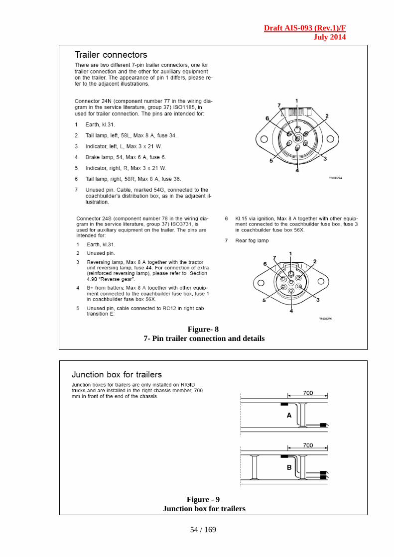
Draft AIS-093 (Rev.1)/F
July 2014
54 / 169
Figure- 8
7- Pin trailer connection and details
Figure - 9
Junction box for trailers
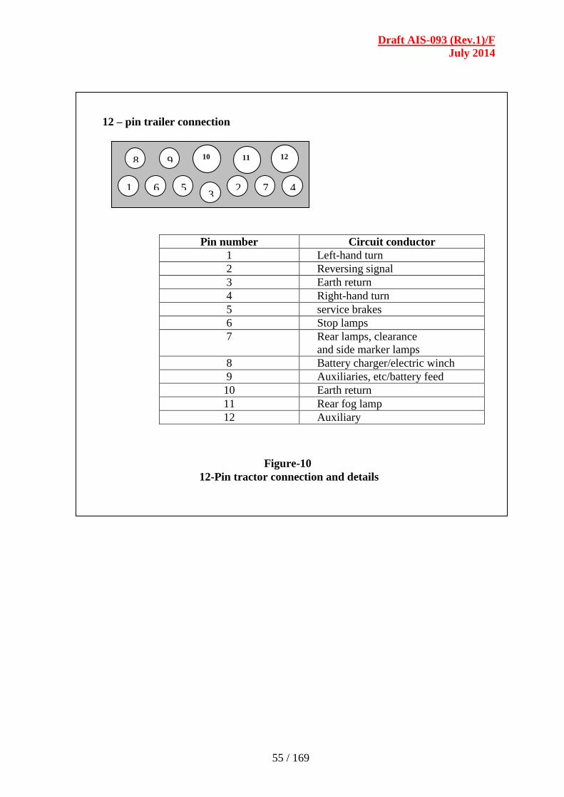
Draft AIS-093 (Rev.1)/F
July 2014
55 / 169
12 – pin trailer connection
Pin number Circuit conductor
1 Left-hand turn
2 Reversing signal
3 Earth return
4 Right-hand turn
5 service brakes
6 Stop lamps
7 Rear lamps, clearance
and side marker lamps
8 Battery charger/electric winch
9 Auxiliaries, etc/battery feed
10 Earth return
11 Rear fog lamp
12 Auxiliary
1 6 5 3
2
1
7 4
8 9 10 11 12
Figure-10
12-Pin tractor connection and details
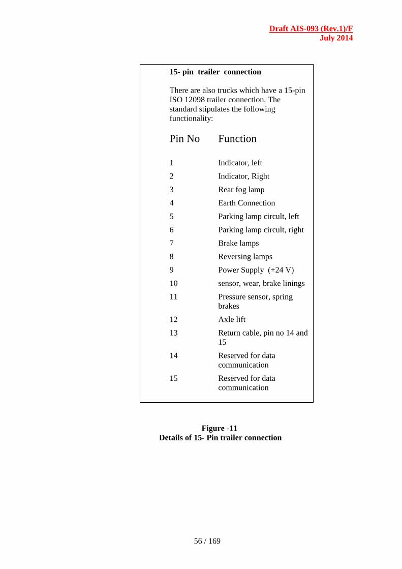
Draft AIS-093 (Rev.1)/F
July 2014
56 / 169
Figure -11
Details of 15- Pin trailer connection
15- pin trailer connection
There are also trucks which have a 15-pin
ISO 12098 trailer connection. The
standard stipulates the following
functionality:
Pin No Function
1 Indicator, left
2 Indicator, Right
3 Rear fog lamp
4 Earth Connection
5 Parking lamp circult, left
6 Parking lamp circult, right
7 Brake lamps
8 Reversing lamps
9 Power Supply (+24 V)
10 sensor, wear, brake linings
11 Pressure sensor, spring
brakes
12 Axle lift
13 Return cable, pin no 14 and
15
14 Reserved for data
communication
15 Reserved for data
communication
__________________________________________________
Draft AIS-093 (Rev.1)/F
July 2014
57 / 169
SECTION - 5.0
ADDITIONAL REQUIREMENTS FOR VEHICLES
CARRYING DANGEROUS AND HAZARDOUS GOODS
WITH REGARD TO THEIR SPECIFIC
CONSTRUCTIONAL FEATURES
LIST OF CONTENTS
5.1 Scope
5.2 Definitions
5.3 Technical Provisions for Base Vehicles
5.4 Technical Provisions for Bodies
5.5 Manner of Display of Class Labels and Identification Marks
5.6 Essential Equipment and Documents to be carried in the Vehicle
5.7 Driver Training Requirements
5.8 Periodic Inspection of Vehicles
5.9 Type Approval Process
Draft AIS-093 (Rev.1)/F
July 2014
58 / 169
5.1 SCOPE :
This chapter applies to the construction of motor vehicles of category N
and their trailers of categories T3 and T4 which are subject to carriage of
dangerous and hazardous goods by road.
5. 2 DEFINITIONS:
5.2.1 "Base vehicle" (hereinafter referred to as "vehicle") means a chassis-
cab vehicle, a tractor for semi-trailer, a trailer-chassis or a trailer
with a self-supporting body intended for the transport of dangerous and
hazardous goods
5.2.1 "Vehicle type" means vehicles, which do not differ essentially with
regard to the constructional features specified in this chapter.
5.2.2 "Vehicle" means any vehicle, whether complete (e.g. one stage built vans,
lorries, tractors, trailers), incomplete (e.g. chassis, chassis-cab, trailer-
chassis) or, completed (e.g. chassis-cab fitted with a bodywork), intended
for the carriage of dangerous and hazardous goods by road.
5.2.3 "EX / II vehicle" or "EX/III vehicle" means a vehicle intended for the
carriage of explosives substances and articles (Class 1).
5.2.4 "FL vehicle" means a vehicle intended for the carriage of liquids having a
flash-point of not more than 65 60 °C (with the exception of diesel fuel
complying with standard EN 590: 1993 2004, gas oil, and heating oil
(light) - UN No.1202 - with a flash-point as specified in standard EN 590:
1993 2004) or flammable gases, in tank-containers, portable tanks or
MEGCs of more than 3 m3 capacity, fixed tanks or demountable tanks of
more than 1 m3 capacity or a battery vehicle of more than 1 m
3 capacity
intended for the carriage of flammable gases.
5.2.5 "OX vehicle" means a vehicle intended for the carriage of hydrogen
peroxide, stabilized or hydrogen peroxide, aqueous solution stabilized with
more than 60 per cent hydrogen peroxide (Class 5.1, UN No. 2015) in
tank-containers or portable tanks of more than 3 m3 capacity, fixed
tanks or demountable tanks of more than 1 m3 capacity.
5.2.6 "AT vehicle" means a vehicle, other than EX/III, FL or OX, intended for
the carriage of dangerous and hazardous goods in tank containers, portable
tanks or MEGCs of more than 3 m3 capacity, fixed tanks or demountable
tanks of more than 1 m3
capacity or a battery vehicle of more than 1 m3
capacity other than an FL vehicle.
Note 1 :
Petroleum Class A - petroleum having a flash-point below 23 degrees
centigrade
Petroleum Class B - petroleum having a flash point of 23 degrees
centigrade and above but below 65 degrees centigrade
Petroleum Class C - petroleum-having flash point of 65 degrees and
above
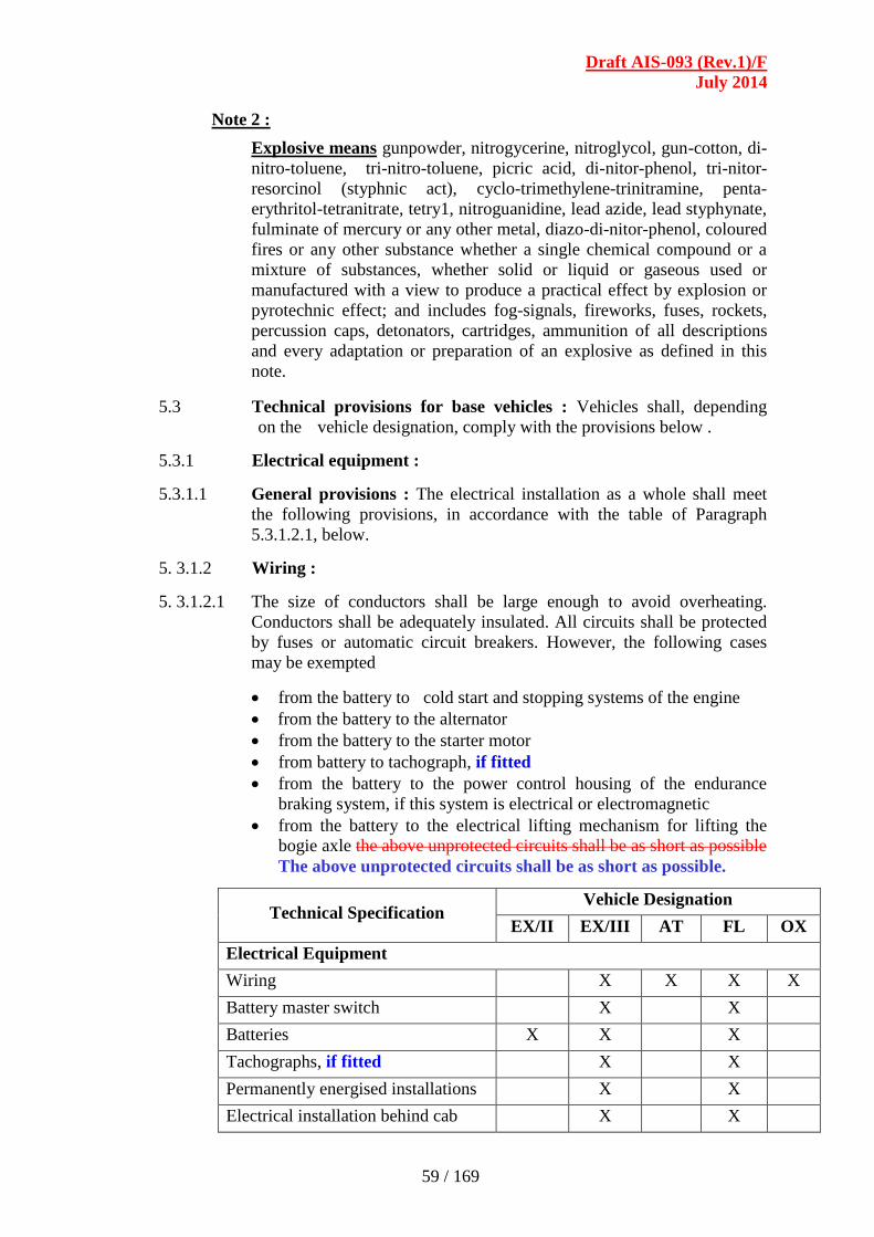
Draft AIS-093 (Rev.1)/F
July 2014
59 / 169
Note 2 :
Explosive means gunpowder, nitrogycerine, nitroglycol, gun-cotton, di-
nitro-toluene, tri-nitro-toluene, picric acid, di-nitor-phenol, tri-nitor-
resorcinol (styphnic act), cyclo-trimethylene-trinitramine, penta-
erythritol-tetranitrate, tetry1, nitroguanidine, lead azide, lead styphynate,
fulminate of mercury or any other metal, diazo-di-nitor-phenol, coloured
fires or any other substance whether a single chemical compound or a
mixture of substances, whether solid or liquid or gaseous used or
manufactured with a view to produce a practical effect by explosion or
pyrotechnic effect; and includes fog-signals, fireworks, fuses, rockets,
percussion caps, detonators, cartridges, ammunition of all descriptions
and every adaptation or preparation of an explosive as defined in this
note.
5.3 Technical provisions for base vehicles : Vehicles shall, depending
on the vehicle designation, comply with the provisions below .
5.3.1 Electrical equipment :
5.3.1.1 General provisions : The electrical installation as a whole shall meet
the following provisions, in accordance with the table of Paragraph
5.3.1.2.1, below.
5. 3.1.2 Wiring :
5. 3.1.2.1 The size of conductors shall be large enough to avoid overheating.
Conductors shall be adequately insulated. All circuits shall be protected
by fuses or automatic circuit breakers. However, the following cases
may be exempted
from the battery to cold start and stopping systems of the engine
from the battery to the alternator
from the battery to the starter motor
from battery to tachograph, if fitted
from the battery to the power control housing of the endurance
braking system, if this system is electrical or electromagnetic
from the battery to the electrical lifting mechanism for lifting the
bogie axle the above unprotected circuits shall be as short as possible
The above unprotected circuits shall be as short as possible.
Technical Specification Vehicle Designation
EX/II EX/III AT FL OX
Electrical Equipment
Wiring X X X X
Battery master switch X X
Batteries X X X
Tachographs, if fitted X X
Permanently energised installations X X
Electrical installation behind cab X X

Draft AIS-093 (Rev.1)/F
July 2014
60 / 169
5. 3.1.2.2 Cables shall be securely fastened and positioned in such a way that
the conductors are adequately protected against mechanical and
thermal stresses.
5. 3.1.3 Battery Master Switch :
5. 3.1.3.1 A switch for breaking the electrical circuits shall be placed as close
to the battery as possible.
5. 3.1.3.2 A control device to facilitate the disconnecting and reconnecting
functions of the switch shall be installed in the driver’s cab. It
shall be readily accessible to the driver and be distinctively
marked. It shall be protected against in advertent operation by
either adding a protective cover, or by using a dual movement
control device or by other suitable means. Additional control
devices may be installed provided they are distinctively marked
and protected against inadvertent operation.
5. 3.1.3.3 It shall be possible to open the switch while the engine is running,
without causing any dangerous excess voltage. Operation of the
switch shall not constitute a fire hazard in an explosive atmosphere;
this can be ensured by using a switch having a casing with protection
degree IP65 in accordance with IEC Standard 60529.
5. 3.1.3.4 The cable connections on the battery master switch shall have a
protection degree IP54. However, this does not apply if these
connections are contained in a housing which may be the battery
box. In this case it is sufficient to insulate the connections against
short circuits, for example with a rubber cap.
5. 3.1.4 Batteries : The battery terminals shall be electrically insulated or
covered by the insulating battery box cover. If the batteries are not
located under the engine bonnet, they shall be fitted in a vented box.
5. 3.1.5 Tachographs : Tachographs, if fitted, on vehicles shall comply with
the requirements stated in AIS-059 as amended from time to time.
5. 3.1.6 Permanently Energised Installations :
5. 3.1.6.1 Those parts of the electrical installation, other than the tachograph,
which remain energised when the battery master-switch is open, shall
be suitable for use in a hazardous area and shall meet the appropriate
requirements of European Standard IEC 60079 and one of IEC
60079-1, 60079-2, 60079-7, 60079-11 and 60079-18. The
requirements for the relevant gas group according to the product
being carried shall be met.
5. 3.1.6.2 Bypass connections to the battery master switch for electrical
equipment which must remain energised when the battery master
switch is open shall be protected against overheating by suitable
means, such as a fuse, a circuit breaker or safety barrier (current
limiter).

Draft AIS-093 (Rev.1)/F
July 2014
61 / 169
5. 3.1.7 Provisions concerning that part of the electrical installation
situated to the rear of the driver's cab : The whole installation
shall be so designed, constructed and protected such that it cannot
provoke any ignition or short-circuit under normal conditions of
vehicle use and that these risks can be minimised in the event of an
impact or deformation. In particular:
5. 3.1.7.1 Wiring : The wiring located behind the drivers cab shall be
protected against impact, abrasion and chafing during normal vehicle
operation. Examples of appropriate protection are given in the
Figures 1, 2, 3 and 4. However, the sensor cables of anti-lock braking
devices do not need additional protection.
5. 3.1.7.2 Lighting : Lamp bulbs with a screw cap shall not be used.
5. 3.1.7.3 Electrical connections : Electrical connections between motor
vehicles and trailers shall have a protection degree IP54 in
accordance with IEC Standard 60529 and be designed to prevent
accidental disconnection. Examples of appropriate connections are
given in ISO 12 098:1994 2004 and ISO 7638:1985 2003 and EN
15207:2006 or any other Indian / International standards as
appropriate.
5. 3.1.7.4 Electrical lifting mechanism : The electrical equipment of the
mechanism for lifting a bogie axle shall be installed outside the
chassis frame in a sealed housing.
5. 3.1.8 Prevention of fire risks : Compliance to Petroleum Rules and
Explosive Rules shall be ensured by DoE PESO.
5. 3.1.8.1 Vehicle cab :
5. 3.1.8.1.1 Only material not readily flammable shall be used in the construction
of the driver's cab. This provision will be deemed to be met if, in
accordance with the procedure specified in ISO Standard 3795:1989,
samples of the following cab components have a burn rate not
exceeding 100 mm / min seat cushions, seat backs, safety belts, head
lining, opening roofs, arm rests, all trim panels including door, front,
rear and side panels, compartment shelves, head restraints, floor
coverings, sun visors, curtains, shades, wheel housing covers, engine
compartment covers, mattress covers and any other interior
materials, including padding and crash-deployed elements, that are
designed to absorb energy on contact by occupants in the event of a
crash.
5. 3.1.8.1.2 Unless the driver's cab is made of not readily flammable materials, a
shield made of metal or other suitable material of the same width as
the tank shall be fitted at the back of the cab. Any windows in the
back of the cab or in the shield shall be hermetically closed and made
of fire resistant safety glass with fire resistant frames. Furthermore,
there shall be a clear space of not less than 15 cm between the tank
and the cab or the shield.
Draft AIS-093 (Rev.1)/F
July 2014
62 / 169
5. 3.1.8.2 Fuel tanks : The fuel tanks for supplying the engine of the vehicle
shall meet the following requirements.
5. 3.1.8.2.1 In the event of any leakage, the fuel shall drain to the ground without
coming into contact with hot parts of the vehicle or the load.
5. 3.1.8.2.2 Fuel tanks containing petrol shall be equipped with an effective
flame trap at the filler opening or with a closure with which the
opening can be kept hermetically sealed.
5. 3.1.8.3 Engine : The engine propelling the vehicle shall be so equipped and
situated to avoid any danger to the load through heating or ignition.
In the case of vehicles designated EX/II and EX/III the engine shall
be placed forward of the front wall of the load compartment: it may
nevertheless be placed under the load compartment, provided this is
done in such a way that any excess heat does not constitute a hazard
to the load by raising the temperature on the inner surface of the load
compartment above 800C. (1)
5. 3.1.8.4 Exhaust system : The exhaust system as well as the exhaust pipes
shall be so directed or protected to avoid any danger to the load
through heating or ignition. Parts of the exhaust system situated
directly below the fuel tank (diesel) shall have a clearance of at least
100 mm or be protected by a thermal shield. The exhaust system of
vehicles designated EX/II and EX/III shall be so constructed and
situated that any excess heat shall not constitute a hazard to the load
by raising the temperature on the inner surface of the load
compartment above 800C. Compliance with these requirements shall
be verified on the completed vehicle.

Draft AIS-093 (Rev.1)/F
July 2014
63 / 169
5.3.1.8.5 Vehicle endurance braking system :
5. 3.1.8.5.1 Endurance braking system means a system intended to stabilize
vehicle speed on a long descent, without the use of the service,
secondary or parking braking systems.
5.3.1.8.5.2 Vehicles equipped with endurance braking systems emitting high
temperatures placed behind the rear wall of the driver's cab shall be
equipped with a thermal shield securely fixed and located between
this system and the tank or load so as to avoid any heating, even
local, of the tank shell or the load. In addition, the thermal shield

Draft AIS-093 (Rev.1)/F
July 2014
64 / 169
shall protect the braking system against any outflow or leakage, even
accidental, of the load. For instance, a protection including a twin-
shell shield shall be considered satisfactory.
5.3.1.8.5.3 Fitment of Endurance braking system shall be as per CMVR & it
shall fulfill the requirements stated in IS 11852 as amended from
time to time.
5.3.1.8.5.4 If a trailer is equipped with an endurance braking system it shall
fulfill the requirements stated in IS 11852, and the provisions of
5.3.1.8.5.3 (a) to (d) above.
5.3.1.8.6 Emergency braking devices for trailers :
5.3.1.8.6.1 Trailers shall be equipped with an effective system for braking or
restraining them if they become detached from the motor vehicle
towing them.
5.3.1.8.6.2 Trailers shall be fitted with an effective braking device, which acts
on all the wheels, is actuated by the drawing vehicle’s service brake
control and automatically stops the trailer in the event of breakage of
the coupling.
5.3.1.8.7 Combustion heaters :
5.3.1.8.7.1 The combustion heaters and their exhaust gas routing shall be
designed, located, protected or covered so as to prevent any
risk of unacceptable heating or ignition of the load. This
requirement shall be considered as fulfilled if the fuel tank and the
exhaust system of the appliance conform to provisions similar to
those prescribed for fuel tanks and exhaust systems of
vehicles in Paragraphs 5.3.1.8.2 and 5.3.1.8.4 respectively.
5.3.1.8.7.2 The combustion heaters shall be put out of operation by at least the
following methods :
(a) Intentional manual switching off from the driver's cab.
(b) Unintentional stopping of the vehicle engine; in this case the
heating device may be restarted manually by the driver.
(c) Start up of a feed pump on the motor vehicle for the dangerous
and hazardous goods carried.
5.3.1.8.7.3 After running is permitted after the combustion heaters have been
put out of operation. For the methods of Paragraphs 5.3.1.8.7.2
(b) and (c) above the supply of combustion air shall be interrupted
by suitable measures after an after-running cycle of not more than
40 seconds. Only heaters shall be used for which proof has
been furnished that the heat exchanger is resistant to the reduced
after running cycle of 40 seconds for the time of their normal
use.
5.3.1.8.7.4 The combustion heater shall be switched on manually. Programming
devices shall be prohibited.

Draft AIS-093 (Rev.1)/F
July 2014
65 / 169
5.3.1.9 Braking equipment : In addition to the following technical
provisions, to be applied in accordance with the table of 5.3.1.2,
motor vehicles and trailers intended for use as transport units for
dangerous and hazardous goods shall fulfill all relevant technical
requirements of IS :11852 including that of Part 9 as amended from
time to time.
5.3.1.10 Speed limiting devices : Motor vehicles (rigid vehicles and
tractors for semi- trailers) with a maximum mass exceeding 12
tonnes, shall be equipped with a speed limiting device complying
to AIS-018. The speed limit value, shall be as that enforced by the
State Road Transport Authority.
5.3.2 Additional requirements concerning complete or completed
EX/II or EX/III vehicles :
5.3.2.1 Materials to be used in the construction of vehicle bodies : No
materials likely to form dangerous compounds with the explosive
substances carried shall be used in the construction of the body.
5.3.2.2 Combustion heaters : Combustion heaters shall not be installed in
load compartments of EX/II and EX/III vehicles. Combustion heaters
shall meet the additional requirements.
(a) The switch may be installed outside the driver's cab.
(b) The device may be switched off from outside the load
compartment and
(c) It is not necessary to prove that the heat exchanger is resistant
to the reduced after running cycle.
5.3.2.3 EX/II vehicles : The vehicles shall be designed, constructed and
equipped so that the explosives are protected from external hazards
and the weather. Shall be approved by DoE PESO.
5.3.2.4 EX/III vehicles : These vehicles shall be closed. The loading
surface, including the front wall, shall be continuous.
5.3.2.5 Load compartment and engine : The engine shall be placed
forward of the front wall of the load compartment; it may
nevertheless be placed under the load compartment, provided this is
done in such a way that any excess heat does not constitute a hazard
to the load by raising the temperature on the inner surface of the load
compartment above 80ºC.
5.3.2.6 Load compartment and exhaust system : The exhaust system of
EX/II and EX/III vehicles or others parts of these complete or
completed vehicles shall be so constructed and situated that any
excess heat shall not constitute a hazard to the load by raising the
temperature on the inner surface of the load compartment above 80
ºC.
Draft AIS-093 (Rev.1)/F
July 2014
66 / 169
5.3.2.7 Electrical equipment :
5.3.2.7.1 The electrical installation on EX/III vehicles shall meet the
requirements of 5.3.1.2.
5.3.2.7.2 The electrical installation in the load compartment shall be dust-
protected.
5.4 Technical Provisions for Bodies :
5.4.1 Additional requirements concerning the construction of the bodies of
complete or completed vehicles intended for the carriage of
dangerous and hazardous goods in packages (other than EX/II and
EX/III vehicles).
5.4.1.1 Combustion heaters shall meet the following requirements :
(a) The switch may be installed outside the driver's cab.
(b) The device may be switched off from outside the load
compartment and
(c) It is not necessary to prove that the heat exchanger is resistant to
the reduced after running cycle.
5.4.1.2 If the vehicle is intended for the carriage of dangerous and hazardous
goods for which a label conforming to the CMV Rules 137, shall be
provided. No fuel tank, power source, combustion air or heating air
intakes as well as exhaust tube outlets required for the operation of
the combustion heater shall be installed in the load compartment. It
shall be ensured that the heating air outlet cannot be blocked by
cargo. The temperature to which packages are heated shall not
exceed 50º C. Heating devices installed inside the load compartments
shall be designed so as to prevent the ignition of an explosive
atmosphere under operating conditions.
5.4.2 Additional requirements concerning the construction of the
bodies of complete or completed vehicles intended for the
carriage of dangerous solids in bulk.
5.4.2.1 If the vehicle is intended for the carriage of dangerous and hazardous
goods for which a label conforming to CMVR rules are provided, no
fuel tanks, power sources, combustion air or heating air intakes as
well as exhaust tube outlets required for the operation of the
combustion heater shall be installed in the load compartment. It shall
be ensured that the heating air outlet cannot be blocked by cargo. The
temperature to which the load is heated shall not exceed 50ºC. This
will be inspected and approved by DoE PESO or its authorised
agency. Heating devices installed inside the load compartments shall
be designed so as to prevent the ignition of an explosive atmosphere
under operating conditions..
5.4.3 Additional requirements concerning complete or completed
vehicles intended for the carriage of temperature controlled self-
reactive substances of class 4.1 and organic peroxides of class 5.2.

Draft AIS-093 (Rev.1)/F
July 2014
67 / 169
5.4.3.1 Insulated, refrigerated and mechanically-refrigerated vehicles
intended for the carriage of temperature controlled self-reactive
substances and organic peroxides shall conform to the following
conditions :
(a) the vehicle shall be such and so equipped as regards its
insulation and means of refrigeration, that the control
temperature prescribed for the substance to be carried is not
exceeded.
(b) the vehicle shall be so equipped that vapours from the
substances or the coolant carried cannot penetrate into the
driver's cab.
(c) a suitable device shall be provided enabling the temperature
prevailing in the loading space to be determined at any time
from the cab.
(d) the loading space shall be provided with vents or ventilating
valves if there is any risk of a dangerous excess pressure arising
therein. Care shall be taken where necessary to ensure that
refrigeration is not impaired by the vents or ventilating valves.
(e) the refrigerant shall not be flammable; and (f) the refrigerating
appliance of a mechanically refrigerated vehicle shall be
capable of operating independently of the engine used to propel
the vehicle.
5.4.3.2 Suitable methods to prevent the control temperature from being
exceeded should be provided. Depending on the method used,
additional provisions concerning the construction of vehicle bodies
may be adopted.
5.4.4 Additional requirements concerning fixed tanks (tank-vehicles)
battery-vehicles and complete or completed vehicles used for the
carriage of dangerous and hazardous goods in demountable
tanks with a capacity greater than 1 m3
or in tank-containers,
portable tanks or MEGCs of a capacity greater than 3 m3
(FL, OX and AT vehicles)
5.4.4.1 General provisions :
5.4.4.1.1 In addition to the vehicle proper, or the units of running gear used in
its stead, a tank-vehicle comprises one or more shells, their items of
equipment and the fittings for attaching them to the vehicle or to the
running-gear units.
5.4.4.1.2 Once the demountable tank has been attached to the carrier vehicle,
the entire unit shall meet the requirements prescribed for tank-
vehicles.
5.4.4.2 Requirements concerning tanks :
5.4.4.2.1 Fixed tanks or demountable tanks made of metal shall meet the
relevant requirements laid down by the Department of Explosives,
Nagpur (DoE) Petroleum and Explosives Safety Organisation
(PESO).
Draft AIS-093 (Rev.1)/F
July 2014
68 / 169
5.4.4.3 Fastenings : Fastenings shall be designed to withstand static and
dynamic stresses in normal conditions of carriage, and minimum
stresses as defined in the case of tank-vehicles, battery-vehicles, and
vehicles carrying demountable tanks.
5.4.4.4 Earthing : Earthing of FL vehicles Tanks made of metal or of fibre-
reinforced plastics material of FL tank-vehicles and battery elements
of FL battery vehicles shall be linked to the chassis by means of at
least one good electrical connection. Any metal contact capable of
causing electrochemical corrosion shall be avoided.
5.4.4.5 Stability of tank-vehicles :
5.4.4.5.1 The height of the centre of gravity of the laden vehicle shall not
exceed 90% of the overall width of the ground level bearing surface
(distance between the outer points of contact with the ground of the
right hand tyre and the left hand tyre of the same axle.
5.4.4.5.2 In addition, tank-vehicles with fixed tanks with a capacity of more
than 3 m3 intended for the carriage of dangerous and hazardous
goods in the liquid or molten state tested with a pressure of less than
4 bar, shall comply with the technical requirements of Section 8.0 of
this code, for lateral stability, as amended, in accordance with the
dates of application specified therein.
5.4.4.6 Under run protection :
5.4.4.6.1 The rear under-run protection and lateral under-run protection
devices shall be in accordance with IS 14812 and IS 14682
respectively as amended from time to time.
Note 1: This provision does not apply to vehicles used for the
carriage of dangerous and hazardous goods in tank
containers, MEGCs or portable tanks. Vehicles with a
tilting shell for the carriage of powdery or granular
substances and a vacuum operated waste tank with a tilting
shell with rear discharge do not require a bumper if the rear
fittings of the shell are provided with a means of protection
which protects the shell in the same way as a bumper.
These may be exempted where the device is incompatible
to the end use.
5.4.4.7 Combustion heaters :
5.4.4.7.1 Combustion heaters shall meet the following additional requirements
:
(a) The switch may be installed outside the driver's cab.
(b) The device may be switched off from outside the load
compartment; and
(c) It is not necessary to prove that the heat exchanger is resistant to
the reduced after running cycle.

Draft AIS-093 (Rev.1)/F
July 2014
69 / 169
In addition for FL vehicles, they shall meet the following
requirements :
(i) The combustion heaters and their exhaust gas routing shall be
designed, located, protected or covered so as to prevent any
unacceptable risk of heating or ignition of the load. This
requirement shall be considered as fulfilled if the fuel tank and
the exhaust system of the appliance conform to provisions
similar to those prescribed for fuel tanks and exhaust systems of
vehicles in clause nos. 5.3.1.2.2 and 5.3.1.2.4.
(iii) The combustion heaters shall be put out of operation by at least
one of the following methods:
(a) Intentional manual switching off from the driver's cab;
(b) Stopping of the vehicle engine; in this case the heating
device may be restarted manually by the driver;
(c) Start up of a feed pump on the motor vehicle for the
dangerous goods carried.
5.4.4.7.2 After-running is permitted after the combustion heaters have been
put out of operation. For the methods of 5.4.4.7.1, (ii), (b) and (c) the
supply of combustion air shall be interrupted by suitable measures
after an after-running cycle of not more than 40 seconds. Only
heaters shall be used for which proof has been furnished that the heat
exchanger is resistant to the reduced after-running cycle of 40
seconds for the time of their normal use. 5.4.4.7.3 If the vehicle is intended for the carriage of dangerous and hazardous
goods for which a label conforming to CMVR is prescribed, no fuel
tanks, power sources, combustion air or heating air intakes as well as
exhaust tube outlets required for the operation of the combustion
heater shall be installed in the load compartment. It shall be ensured
that the heating air outlet cannot be blocked by cargo. The
temperature to which the load is heated shall not exceed 50ºC.
Heating devices installed inside the load compartments shall be
designed so as to prevent the ignition of an explosive atmosphere
under operating conditions.
5.5 Manner of display of class labels and identification marks : The
display of class labels shall be as per Rule 130 of Central Motor
Vehicle Rules, 1989.
5.6 Essential equipment and documents to be carried in the vehicle :
5.6.1 The documents to be carried in the vehicle shall be as per the
requirements specified in Rules 131 to 136 of CMVR.
5.6.1.1 Placarding and marking : Transport units carrying dangerous and
hazardous goods shall be placarded and marked in conformity with
Central Motor Vehicle Rules, 1989 and DoE PESO rules.
Draft AIS-093 (Rev.1)/F
July 2014
70 / 169
5.6.1.2 Fire -fighting appliances.
5.6.1.2.1 Every transport unit carrying dangerous and hazardous goods shall
be equipped with fire extinguishers as per Petroleum rules or
PESO 2002 published in 2012;
(a) A portable fire extinguisher (10 kg. dry chemical powder or
equivalent) suitable for extinguishing petroleum fire shall be
carried in an easily accessible and detachable position and
away from the discharge faucets on every vehicle
transporting petroleum by road. Additionally, one dry
chemical powder type fire extinguisher of 1 kg. Capacity shall
be carried in the driver's cabin of the vehicle.
(a) At least one portable fire extinguisher of minimum capacity 2
kg dry powder (or equivalent rating for suitable
extinguishants) suitable for fighting a fire in the engine or cab
of the transport unit, and such that, if it is used to fight a fire
involving the load, it does not aggravate the fire and, if
possible, controls it; however, if the vehicle is - 6 - equipped
with a fixed fire extinguisher, automatic or easily brought
into action for fighting a fire in the engine, the portable
extinguisher need not be suitable for fighting a fire in the
engine.
(b) In addition to the equipment prescribed under (a) above, at
least one portable fire extinguisher of minimum capacity 6 kg
dry powder (or equivalent rating for suitable extinguishants)
suitable for fighting a tyre/brake fire or one involving the
load, and such that, if it is used to fight a fire in the engine or
cab of the transport unit, it does not aggravate the fire.
Motor vehicles with a maximum permissible mass of 3.5
tonnes or less may be equipped with a portable fire
extinguisher of a minimum capacity of 2 kg of powder.
(c) (b) For vehicles of category EX (carrying explosives) – two fire
extinguishers, one capable of dousing electrical fires and the other
capable handling fires due to engine, tyres etc. This is as per
Explosive Rules.
5.6.1.2.2 The extinguishing agents contained in the fire extinguishers with
which a transport unit is equipped shall be such that they are not
liable to release toxic gases into the driver's cab or under the
influence of the heat of the fire.
5.6.1.2.3 The portable fire extinguishers conforming to the provisions above
shall be fitted with a seal verifying that they have not been used. In
addition, they shall bear a mark of compliance with a standard
recognized by a competent authority and an inscription indicating the
expiry date (month, year).
5.6.1.3 Miscellaneous equipment : Every transport unit carrying dangerous
and hazardous goods shall be equipped with :
Draft AIS-093 (Rev.1)/F
July 2014
71 / 169
(a) For each vehicle, at least one wheel chock, of a size suited to
the weight of the vehicle and to the diameter of the wheels.
(b) The necessary equipment to take the general actions referred
to in the safety instructions, in particular :
A suitable warning vest or warning clothing for each
member of the vehicle crew.
A pocket lamp for each member of the vehicle crew.
5.7 Driver training requirements : Driver training and licensing shall
be as per Rule 9 of the Central Motor Vehicle Rules, 1989.
5.8 Periodic Inspection of vehicles : The periodic inspection of the
hazardous or dangerous goods carrying vehicles would be
necessary with respect to the following.
(i) Obtaining the fitness of the vehicle which is required yearly or a
lesser period.
(ii) Inspection of the vehicle externally, internally and also by
ultrasonic inspection.
(iii) Inspection of the vehicle for the DoE PESO documents,
emergency information panel, hazard class labels etc.
5.9 Type approval process :
5.9.1 Approvals of PESO (Petroleum & Explosives Safety
Organisation ) for tankers / trailers :
5.9.1.1 Tanker / Bullet : The tanker manufacturer and / or the bullet
manufacturer shall approach the Department of Explosives for
the approval of the design and the prototype as per the existing
procedure.
5.9.2 Vehicle type approval :
5.9.2.1 The type approval of the basic vehicle chassis and bodies for vehicles
and or trailers / semi-trailers will be carried out by the testing
agencies specified in Rule 126 of Central Motor Vehicle Rules,
1989.
5.9.2.2 The vehicle manufacturer shall submit his application with all the
necessary documents and also the documents with regard to its
specific constructional features given at Annexure III of this code,
to the testing agency for compliance to to this section in
addition to the Central Motor Vehicle Rules, 1989 requirements.
5.9.2.3 A vehicle representative of the type to be approved shall be
submitted to the testing agency responsible for conducting the
approval tests. However it can be only chassis as the body and
installations are approved by DoE PESO.
5.9.2.4 The testing agency shall issue type approval for the basic vehicle
after verifying all the necessary compliance requirements stated in
Central Motor Vehicle Rules, 1989 and the provisions stated in this
section.
Draft AIS-093 (Rev.1)/F
July 2014
72 / 169
5.9.2.5 Similarly, the trailer / semi-trailer manufacturer shall submit his
application with all the necessary documents , referred in Section 7.0
of this code to the testing agencies referred in Rule 126 of Central
Motor Vehicle Rules, 1989
5.9.2.6 The testing agency shall issue type approval for the trailer / semi-
trailer after verifying all the necessary compliance requirements
stated in Central Motor Vehicle Rules, 1989 and the provisions stated
in Section 7.0 of this Code.
5.9.3 Vehicle registration :
5.9.3.1 The integrated process of vehicle registration will be carried out by the
registering authorities after necessary verification of the documents
of vehicle approval and the tanker / bullet approval by DoE PESO or
their authorised third party evaluators.
5.9.3.2 The system of vehicle registration for dangerous and hazardous
goods carrying vehicles are as indicated in the flow chart below.
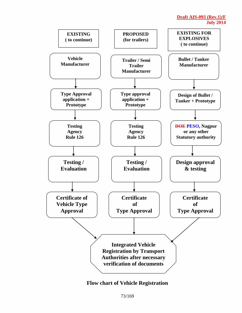
Draft AIS-093 (Rev.1)/F
July 2014
73/169
Flow chart of Vehicle Registration
Vehicle
Manufacturer
EXISTING
( to continue)
PROPOSED
(for trailers)
EXISTING FOR
EXPLOSIVES
( to continue)
Type Approval
application +
Prototype
Testing
Agency
Rule 126
Testing /
Evaluation
Certificate of
Vehicle Type
Approval
Trailer / Semi
Trailer
Manufacturer
Type approval
application +
Prototype
Testing
Agency
Rule 126
Testing /
Evaluation
Certificate
of
Type Approval
Bullet / Tanker
Manufacturer
Design of Bullet /
Tanker + Prototype
DOE PESO, Nagpur
or any other
Statutory authority
Design approval
& testing
Certificate
of
Type Approval
Integrated Vehicle
Registration by Transport
Authorities after necessary
verification of documents
Draft AIS-093 (Rev.1)/F
July 2014
74 /169
SECTION - 6.0
REQUIREMENTS OF CONTAINER CARRIERS AND TANKERS
LIST OF CONTENTS
6.1 Scope
6.2 Definitions of Freight Container
6.3 Container Types
6.4 Container Size Designations and Sizes Codes
6.5 Stacking of Load
6.6 Twist Locks
6.7 Container securing arrangements
6.8 Attaching Sub-frames and Bodies
6.9 Tanker Mounting
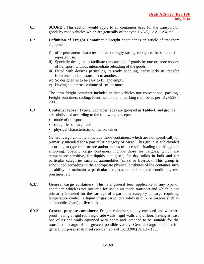
Draft AIS-093 (Rev.1)/F
July 2014
75/169
6.1 SCOPE : This section would apply to all containers used for the transport of
goods by road vehicles which are generally of the type 1AAA, 1AA, 1AX etc.
6.2 Definition of Freight Container : Freight container is an article of transport
equipment,
i) of a permanent character and accordingly strong enough to be suitable for
repeated use.
ii) Specially designed to facilitate the carriage of goods by one or more modes
of transport, without intermediate reloading of the goods.
iii) Fitted with devices permitting its ready handling, particularly its transfer
from one mode of transport to another.
iv) So designed as to be easy to fill and empty.
v) Having an internal volume of 1m3 or more.
The term freight container includes neither vehicles nor conventional packing.
Freight containers coding, Identification, and marking shall be as per IS : 6928 -
2001.
6.3 Container types : Typical container types are grouped in Table-1, and groups
are subdivided according to the following concepts,
mode of transport,
categories of cargo and
physical characteristics of the container.
General cargo containers include those containers, which are not specifically or
primarily intended for a particular category of cargo. This group is sub-divided
according to type of structure and/or means of access for loading (packing) and
emptying. Specific cargo containers include those for cargoes, which are
temperature sensitive, for liquids and gases, for dry solids in bulk and for
particular categories such as automobiles (cars), or livestock. This group is
subdivided according to the appropriate physical attributes of the container such
as ability to maintain a particular temperature under stated conditions, test
pressures, etc.
6.3.1 General cargo containers: This is a general term applicable to any type of
container which is not intended for use in air mode transport and which is not
primarily intended for the carriage of a particular category of cargo requiring
temperature control, a liquid or gas cargo, dry solids in bulk or cargoes such as
automobiles (cars) or livestock.
6.3.2 General purpose containers: Freight container, totally enclosed and weather-
proof having a rigid roof, rigid side walls, rigid walls and a floor, having at least
one of its end walls equipped with doors and intended to be suitable for the
transport of cargo of the greatest possible variety. General cargo container for
general purposes shall meet requirements of IS:13288 (Part1) - 1993.

Draft AIS-093 (Rev.1)/F
July 2014
76/169
6.3.3 Specific purpose container: This is a general term applicable to all general
cargo containers having constructional features either for the “special purpose”
of facilitating packing and emptying other than by means of doors at one end of
the container, or for other specific purposes such as ventilation.
6.3.4 Closed ventilated container: Container of a closed type, similar to a general
purpose container, but specifically designed for carriage of cargo where
ventilation, either natural or mechanical is necessary.
6.3.5 Open top container: Freight container similar in all respects to a general
purpose container except that it has no rigid roof but may have flexible and
movable or removable cover, for example one made of canvas or plastic or
reinforced plastic material normally supported on movable or removable roof
bows. Such containers may have movable or removable top end transverse
members above their end doors, as shown in Figure – 6.
6.3.6 Platform based container open sided: This is a general term applied to any
general cargo container which does not have rigid side walls or equivalent
structures capable of withstanding all of the loads that may be withstood or
transmitted by a side wall of a general purpose container and which, for this
reason, has a base structure similar to that of a platform. Platform based
containers , as shown in Figure 4 and 5, shall comply the requirements of
IS 13288 (Part5) -1992.
6.3.6.1 Platform based container open sided with complete superstructure :
Platform based container, having a permanently fixed longitudinal load carrying
structure between end at the top.
Note: The term “load” as used refers to a static/dynamic type load, not a cargo
load.
6.3.6.2 Platform based container with incomplete superstructure and fixed ends :
Platform based container without any permanently fixed longitudinal load
carrying structure between ends other than at the base.
6.3.6.3 Platform based containers with incomplete superstructure and folding ends
: Platform based container with incomplete superstructure but having folded end
frames with a complete transverse structural connection between corner posts.
6.3.7 Platform container : Loadable platform having no superstructure whatever but
having the same length and width as the base of a container of the same series
and equipped with top and bottom corner fittings, located in the plan view as on
containers of series 1, so that some of the same securing and fitting devices can
be used.
6.3.8 Specific cargo containers : This is a general term applied to those types of
containers, which are primarily intended for the carriage of particular categories
of cargo.

Draft AIS-093 (Rev.1)/F
July 2014
77/169
6.3.9 Thermal container : Freight container built with insulating walls, doors,
floor and roof which retard the rate of heat transmission between the inside and
the outside of the container. Thermal containers shall meet the requirements of
IS:13288 (Part2) 1993.
6.3.10 Insulated container : Thermal container with the use of devices for cooling and
/ or heating.
6.3.11 Refrigerated container (expendable refrigerant) : Thermal container using a
means of cooling such as ice, dry ice, with or without sublimation control, or
liquefied gases, with or without evaporation control. It is implicit in this
definition that such a container requires no external power supply or fuel supply.
Refrigerated containers are as shown in Figure 1 and Figure 2.
6.3.12 Mechanically refrigerated container : Thermal container served by
refrigerating appliance (mechanical compressor unit, absorption unit, etc).
6.3.13 Heated container: These are thermal container served by heat producing
appliance.
6.3.14 Refrigerated and heated container : Thermal container served by
refrigerating appliance (mechanical or expendable refrigerant) and heat
producing appliance.
6.3.15 Tank Container : A freight container which includes two basic elements, the
tank or tanks and frame work, and complies with the requirements of IS:13288 (
Part 3) - 2002 as shown in Figure – 3.
6.3.16 Terminology of Tank Containers :
6.3.16.1 Frame work: The tank mountings, end structure and all load bearing elements
not present for the purposes of containing cargo, which transmit static and
dynamic forces arising out of the lifting, handling, securement and transporting
of the tank container as a whole.
6.3.16.2 Tank or tanks: The vessel or vessels, and associated piping and fittings which
are designed to confine the goods carried.
6.3.16.3 Compartment: Any fluid-tight section of the tank formed by the shell, ends or
bulkheads. It should be noted that baffles surge plates to other perforated plates
do not form tank compartments within the meaning of this definition.
6.3.16.4 Dry bulk container : Container consisting of a cargo-carrying structure, firmly
secured within an ISO series 1 frame work, for the carriage of dry solids in bulk
without packaging.
6.3.16.5 Named cargo types: Various types of containers such as automobile car)
containers, live stock containers and others, are built in general accordance with
ISO container requirements either solely or primarily for the carriage of a named
cargo.

Draft AIS-093 (Rev.1)/F
July 2014
78/169
6.4 Container size designations and sizes codes :
6.4.1 Series 1 containers, are intended for intercontinental use. For series 1 containers,
the size designations are given in the attached Table-1.
6.4.1.1 Container size codes : The size codes of the containers shall be as per
IS:6928:2001. Normally the size code consists of two Arabic numerals.
For containers having a nominal length equal to or greater than 3000 mm, the
first numeral denotes length and the second numeral denotes height and the
presence or absence of a gooseneck tunnel.
6.4.2 Definitions related to Dimensions and Capacities :
6.4.2.1 External dimensions :
6.4.2.1.1 Nominal dimensions : Nominal dimensions are those dimensions, neglecting
tolerances, and rounded to the nearest convenient figure, by which a container
may be identified.
6.4.2.1.2 Actual dimensions : These are maximum overall dimensions (including
positive tolerances where these are applicable) for length, width and height
measured along the exterior edges of the container.
Note : Diagonal tolerances, applicable to any of the six “faces” of a container
are expressed in terms of the allowable differences between the lengths of the
diagonal (measured between the centers of the corner fitting apertures) of the
face in question. These diagonal tolerances are allowable even when the edge
dimensions for the surface in question are at their maximum values.
6.4.2.1.3 Internal dimensions : These are the dimensions of the largest unobstructed
rectangular parallelepiped, which could be inscribed in the container if inward
protrusions of the top corner fittings are neglected. Except where otherwise
stated, the term “internal dimensions” is synonymous with the term
“unobstructed internal dimensions”.
6.4.2.1.4 Door opening : This term is usually reserved for the definition of the size of the
door aperture, i.e. the width and height dimensions of the largest unobstructed
parallelopiped, which could possibly be entered into the container via the door
aperture in question. Minimum door openings of the container shall be as per IS
13288 (Part1): 1993 and IS 13288 (Part2): 2001.
6.4.2.1.5 Internal volume : Volume determined by multiplying the internal dimensions,
i.e. the product of internal length, width and height. Except when otherwise
stated the term “internal volume” is synonymous with the terms “unobstructed
internal volume”, “capacity” or “unobstructed capacity”.
6.4.3 Definitions related to the Rating and Masses :
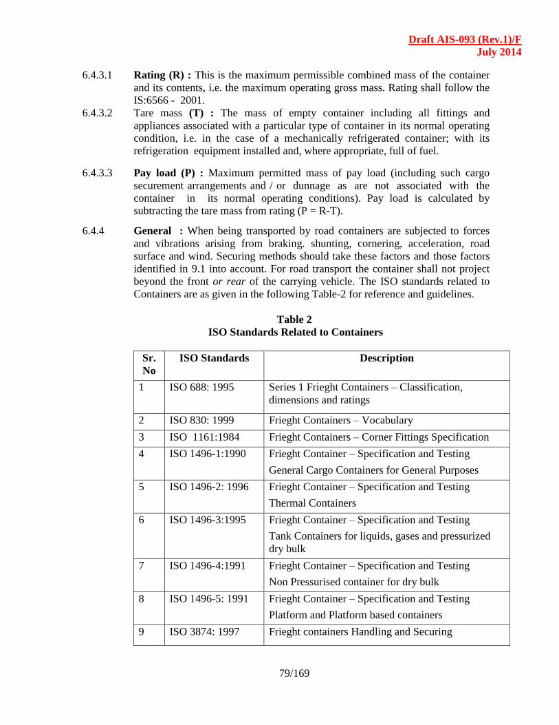
Draft AIS-093 (Rev.1)/F
July 2014
79/169
6.4.3.1 Rating (R) : This is the maximum permissible combined mass of the container
and its contents, i.e. the maximum operating gross mass. Rating shall follow the
IS:6566 - 2001.
6.4.3.2 Tare mass (T) : The mass of empty container including all fittings and
appliances associated with a particular type of container in its normal operating
condition, i.e. in the case of a mechanically refrigerated container; with its
refrigeration equipment installed and, where appropriate, full of fuel.
6.4.3.3 Pay load (P) : Maximum permitted mass of pay load (including such cargo
securement arrangements and / or dunnage as are not associated with the
container in its normal operating conditions). Pay load is calculated by
subtracting the tare mass from rating (P = R-T).
6.4.4 General : When being transported by road containers are subjected to forces
and vibrations arising from braking. shunting, cornering, acceleration, road
surface and wind. Securing methods should take these factors and those factors
identified in 9.1 into account. For road transport the container shall not project
beyond the front or rear of the carrying vehicle. The ISO standards related to
Containers are as given in the following Table-2 for reference and guidelines.
Table 2
ISO Standards Related to Containers
Sr.
No
ISO Standards Description
1 ISO 688: 1995
Series 1 Frieght Containers – Classification,
dimensions and ratings
2 ISO 830: 1999 Frieght Containers – Vocabulary
3 ISO 1161:1984 Frieght Containers – Corner Fittings Specification
4 ISO 1496-1:1990
Frieght Container – Specification and Testing
General Cargo Containers for General Purposes
5 ISO 1496-2: 1996
Frieght Container – Specification and Testing
Thermal Containers
6 ISO 1496-3:1995
Frieght Container – Specification and Testing
Tank Containers for liquids, gases and pressurized
dry bulk
7 ISO 1496-4:1991
Frieght Container – Specification and Testing
Non Pressurised container for dry bulk
8 ISO 1496-5: 1991
Frieght Container – Specification and Testing
Platform and Platform based containers
9 ISO 3874: 1997 Frieght containers Handling and Securing

Draft AIS-093 (Rev.1)/F
July 2014
80/169
10 ISO 6346: 1995 Frieght Containers – coding, identification and
marking
11 ISO 8323: 1985
Frieght Containers – Air /surface (intermodal)
general purpose Containers – Specification and tests
Figure 1
Refrigerated Container
Figure 2
High Cube Refrigerated Container
Figure 3
Tank Container
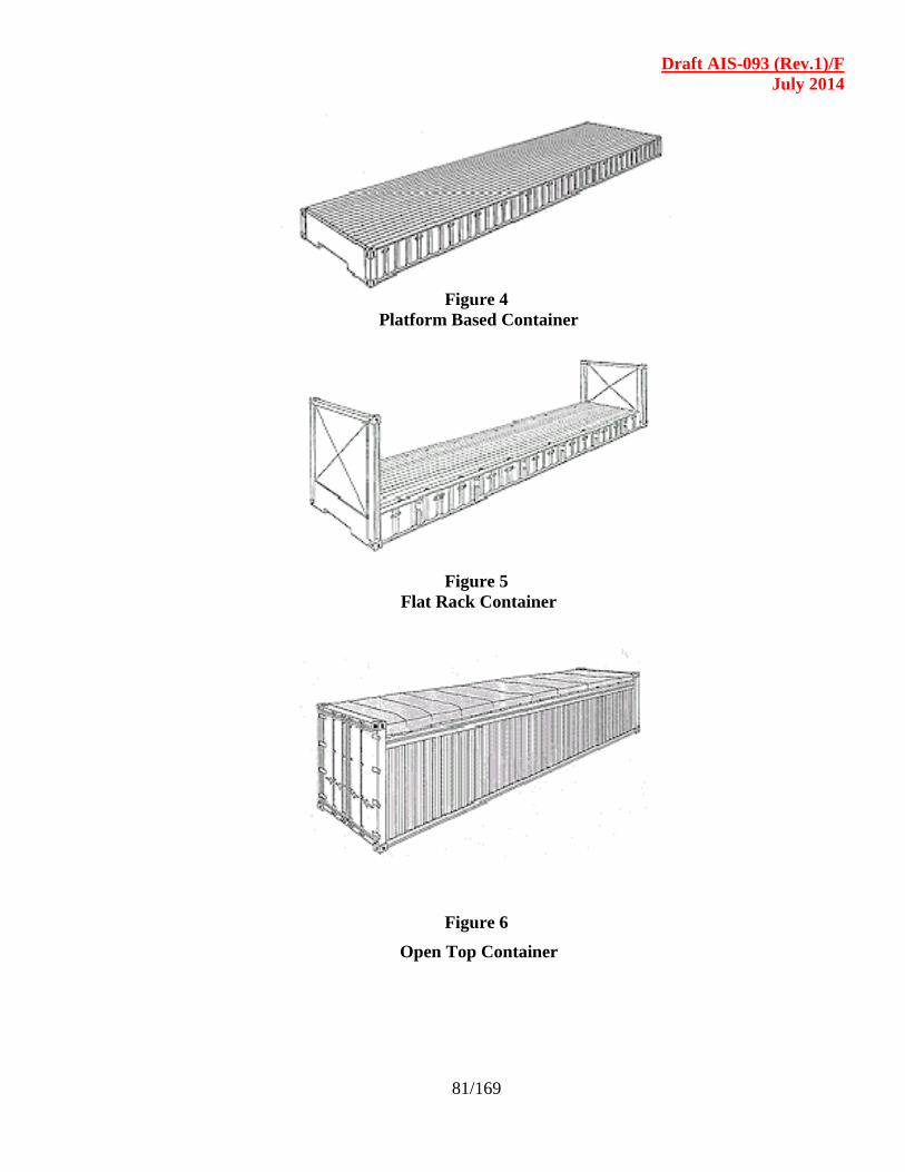
Draft AIS-093 (Rev.1)/F
July 2014
81/169
Figure 4
Platform Based Container
Figure 5
Flat Rack Container
Figure 6
Open Top Container

Draft AIS-093 (Rev.1)/F
July 2014
82/169
Figure 7
High Cube Container
6.5 Recommendations for Stacking of Load :
6.5.1 Loads : The load stacked in vehicles must be secured for protection against the
following motions during transport .
Impact against loading docks
Braking and acceleration
Sway on curves
Coupling impact
Vibration and shocks
6.5.2 Loading pattern : Loading pattern should be planned for each commodity prior
to loading to avoid overloading at any one end.
6.5.3 Loading intensity : Maximum permissible intensity of loading shall not exceed
For 20-ft container 4.5 ton/m2
For 40-ft container 3 ton/m2
6.5.4 Centre of gravity : Heavy goods should not be placed on top of the lighter
goods. The center of gravity be maintained in lower half of the height.
Longitudinally, the centre of gravity shall not be out of the middle by
following limits:
20-ft container 0.6 m on both sides
40-ft container 0.9 m on both sides
6.6 Twist locks : Twist locks shall be provided to hold the containers safely and
rigidly on the load body platform of the vehicle, or on the base of a trailer /
semi-trailer. These twist locks shall comply with the requirements specified in
IS : 7622 – 2001.
6.6.1 Design dimensions of twist locks :
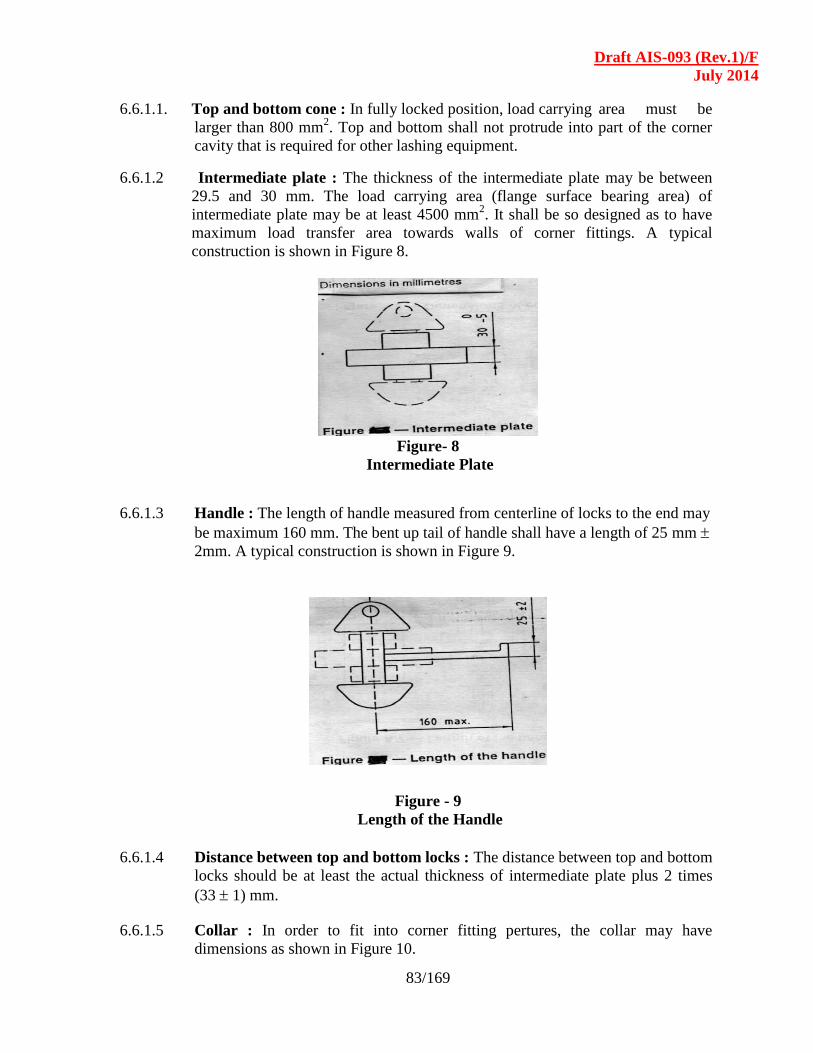
Draft AIS-093 (Rev.1)/F
July 2014
83/169
6.6.1.1. Top and bottom cone : In fully locked position, load carrying area must be
larger than 800 mm2. Top and bottom shall not protrude into part of the corner
cavity that is required for other lashing equipment.
6.6.1.2 Intermediate plate : The thickness of the intermediate plate may be between
29.5 and 30 mm. The load carrying area (flange surface bearing area) of
intermediate plate may be at least 4500 mm2. It shall be so designed as to have
maximum load transfer area towards walls of corner fittings. A typical
construction is shown in Figure 8.
Figure- 8
Intermediate Plate
6.6.1.3 Handle : The length of handle measured from centerline of locks to the end may
be maximum 160 mm. The bent up tail of handle shall have a length of 25 mm
2mm. A typical construction is shown in Figure 9.
Figure - 9
Length of the Handle
6.6.1.4 Distance between top and bottom locks : The distance between top and bottom
locks should be at least the actual thickness of intermediate plate plus 2 times
(33 1) mm.
6.6.1.5 Collar : In order to fit into corner fitting pertures, the collar may have
dimensions as shown in Figure 10.
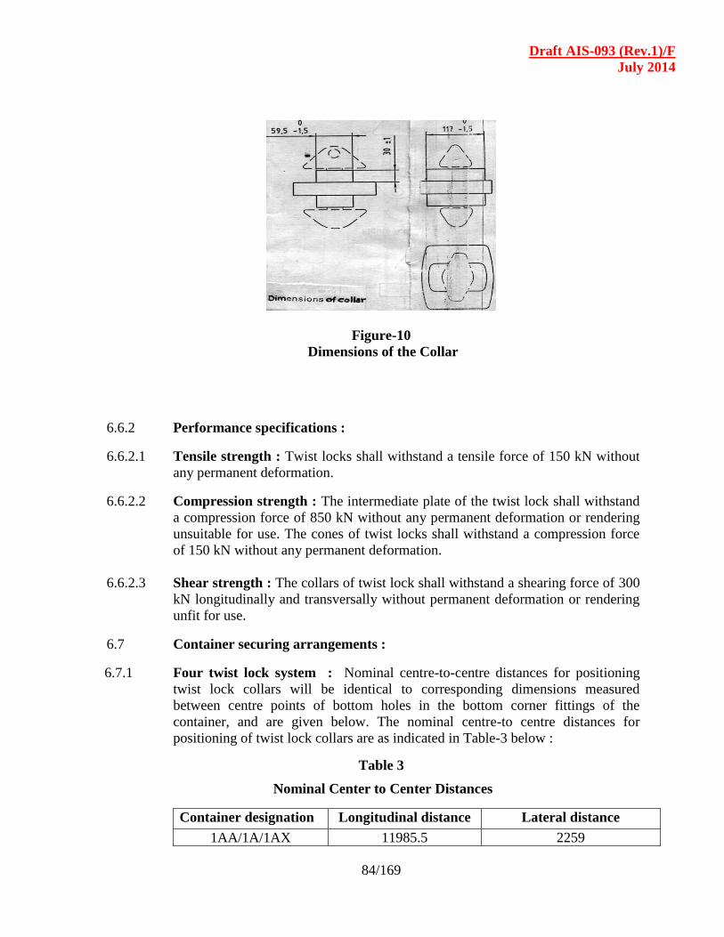
Draft AIS-093 (Rev.1)/F
July 2014
84/169
Figure-10
Dimensions of the Collar
6.6.2 Performance specifications :
6.6.2.1 Tensile strength : Twist locks shall withstand a tensile force of 150 kN without
any permanent deformation.
6.6.2.2 Compression strength : The intermediate plate of the twist lock shall withstand
a compression force of 850 kN without any permanent deformation or rendering
unsuitable for use. The cones of twist locks shall withstand a compression force
of 150 kN without any permanent deformation.
6.6.2.3 Shear strength : The collars of twist lock shall withstand a shearing force of 300
kN longitudinally and transversally without permanent deformation or rendering
unfit for use.
6.7 Container securing arrangements :
6.7.1 Four twist lock system : Nominal centre-to-centre distances for positioning
twist lock collars will be identical to corresponding dimensions measured
between centre points of bottom holes in the bottom corner fittings of the
container, and are given below. The nominal centre-to centre distances for
positioning of twist lock collars are as indicated in Table-3 below :
Table 3
Nominal Center to Center Distances
Container designation Longitudinal distance Lateral distance
1AA/1A/1AX 11985.5 2259
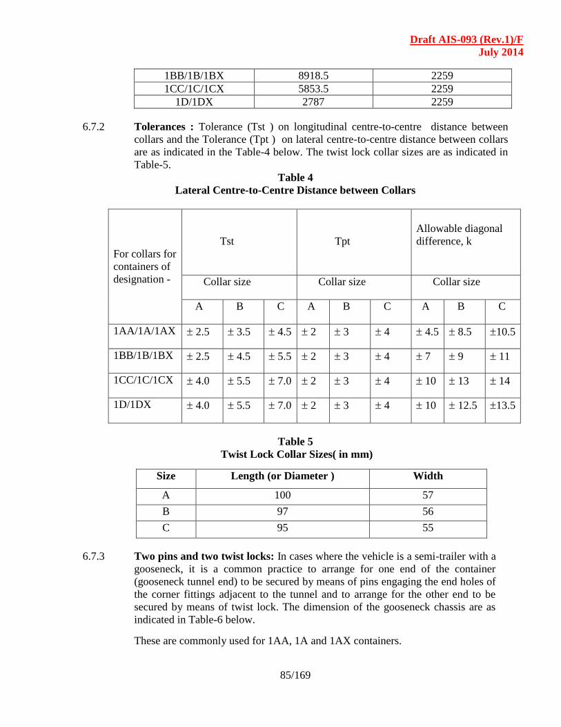
Draft AIS-093 (Rev.1)/F
July 2014
85/169
1BB/1B/1BX 8918.5 2259
1CC/1C/1CX 5853.5 2259
1D/1DX 2787 2259
6.7.2 Tolerances : Tolerance (Tst ) on longitudinal centre-to-centre distance between
collars and the Tolerance (Tpt ) on lateral centre-to-centre distance between collars
are as indicated in the Table-4 below. The twist lock collar sizes are as indicated in
Table-5.
Table 4
Lateral Centre-to-Centre Distance between Collars
For collars for
containers of
designation -
Tst
Tpt
Allowable diagonal
difference, k
Collar size Collar size Collar size
A B C A B C A B C
1AA/1A/1AX 2.5 3.5 4.5 2 3 4 4.5 8.5 10.5
1BB/1B/1BX 2.5 4.5 5.5 2 3 4 7 9 11
1CC/1C/1CX 4.0 5.5 7.0 2 3 4 10 13 14
1D/1DX 4.0 5.5 7.0 2 3 4 10 12.5 13.5
Table 5
Twist Lock Collar Sizes( in mm)
Size Length (or Diameter ) Width
A 100 57
B 97 56
C 95 55
6.7.3 Two pins and two twist locks: In cases where the vehicle is a semi-trailer with a
gooseneck, it is a common practice to arrange for one end of the container
(gooseneck tunnel end) to be secured by means of pins engaging the end holes of
the corner fittings adjacent to the tunnel and to arrange for the other end to be
secured by means of twist lock. The dimension of the gooseneck chassis are as
indicated in Table-6 below.
These are commonly used for 1AA, 1A and 1AX containers.
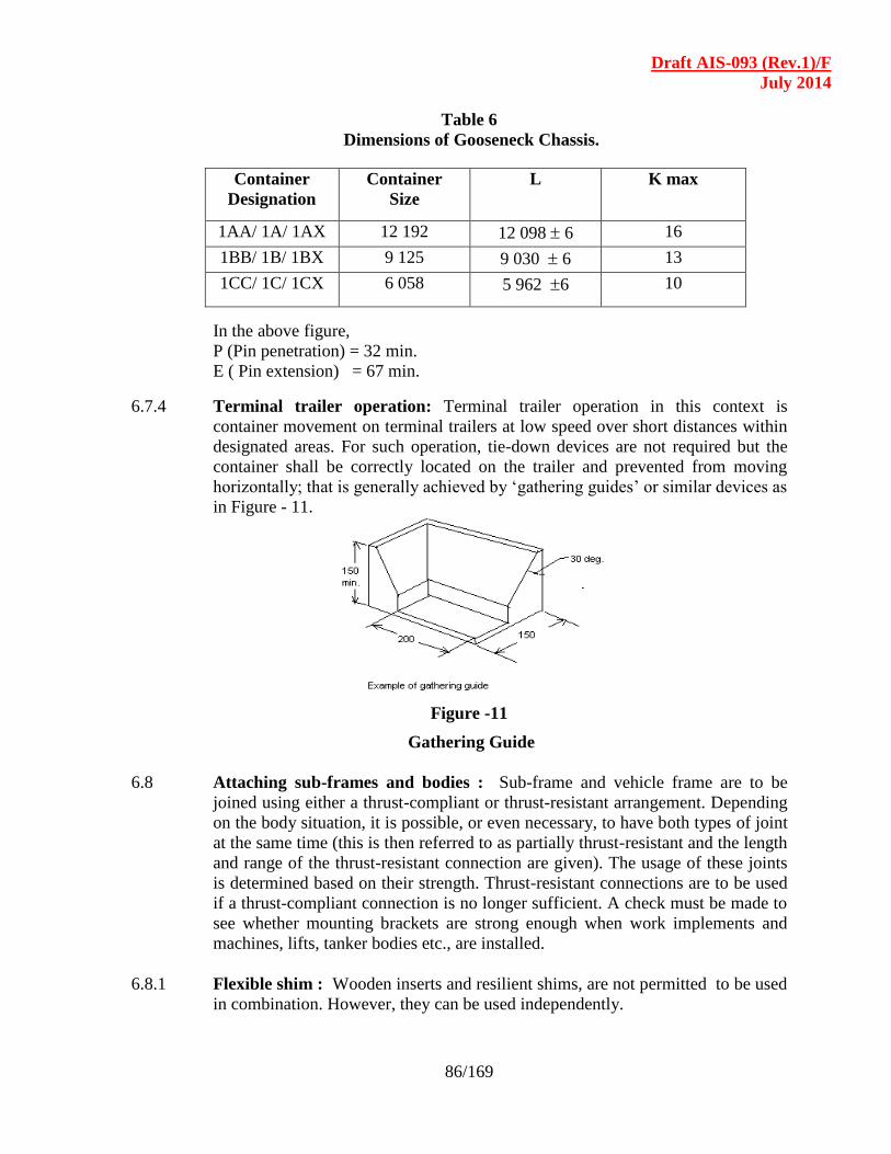
Draft AIS-093 (Rev.1)/F
July 2014
86/169
Table 6
Dimensions of Gooseneck Chassis.
Container
Designation
Container
Size
L K max
1AA/ 1A/ 1AX 12 192 12 098 6 16
1BB/ 1B/ 1BX 9 125 9 030 6 13
1CC/ 1C/ 1CX 6 058 5 962 6 10
In the above figure,
P (Pin penetration) = 32 min.
E ( Pin extension) = 67 min.
6.7.4 Terminal trailer operation: Terminal trailer operation in this context is
container movement on terminal trailers at low speed over short distances within
designated areas. For such operation, tie-down devices are not required but the
container shall be correctly located on the trailer and prevented from moving
horizontally; that is generally achieved by ‘gathering guides’ or similar devices as
in Figure - 11.
Figure -11
Gathering Guide
6.8 Attaching sub-frames and bodies : Sub-frame and vehicle frame are to be
joined using either a thrust-compliant or thrust-resistant arrangement. Depending
on the body situation, it is possible, or even necessary, to have both types of joint
at the same time (this is then referred to as partially thrust-resistant and the length
and range of the thrust-resistant connection are given). The usage of these joints
is determined based on their strength. Thrust-resistant connections are to be used
if a thrust-compliant connection is no longer sufficient. A check must be made to
see whether mounting brackets are strong enough when work implements and
machines, lifts, tanker bodies etc., are installed.
6.8.1 Flexible shim : Wooden inserts and resilient shims, are not permitted to be used
in combination. However, they can be used independently.
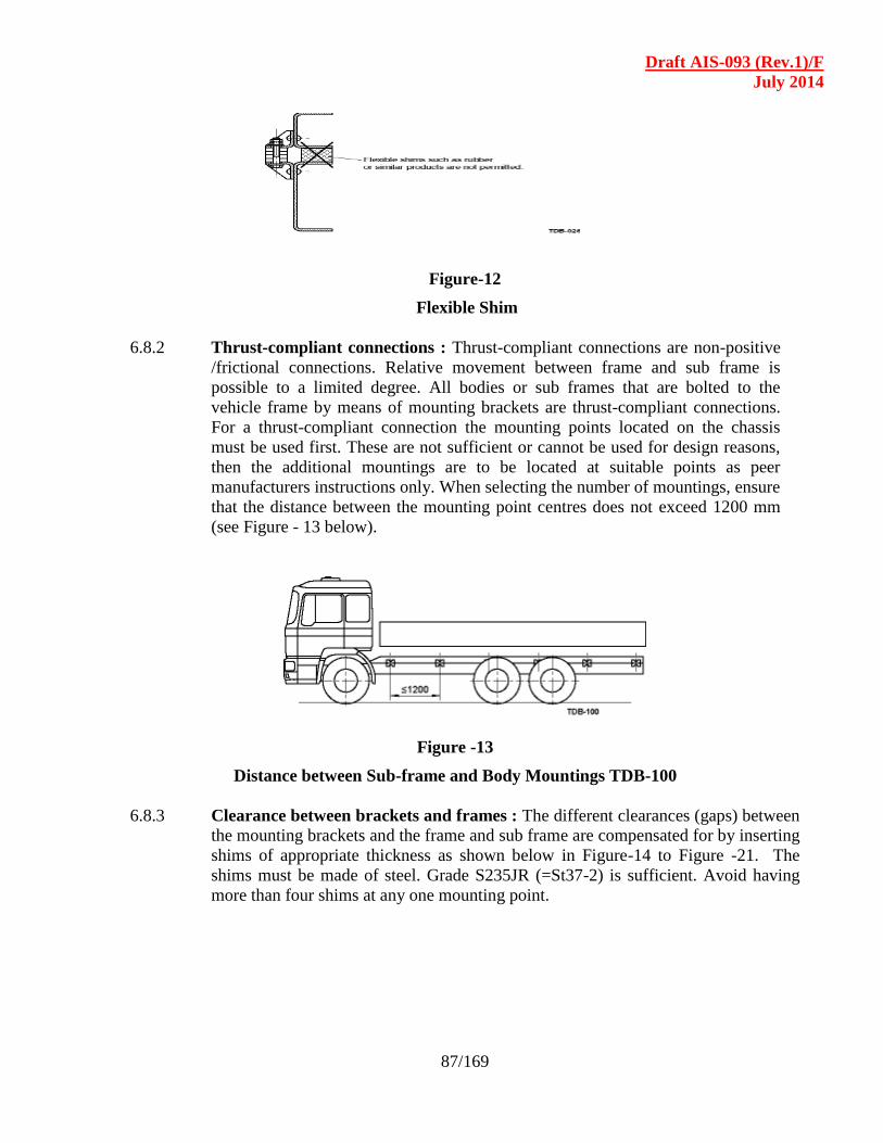
Draft AIS-093 (Rev.1)/F
July 2014
87/169
Figure-12
Flexible Shim
6.8.2 Thrust-compliant connections : Thrust-compliant connections are non-positive
/frictional connections. Relative movement between frame and sub frame is
possible to a limited degree. All bodies or sub frames that are bolted to the
vehicle frame by means of mounting brackets are thrust-compliant connections.
For a thrust-compliant connection the mounting points located on the chassis
must be used first. These are not sufficient or cannot be used for design reasons,
then the additional mountings are to be located at suitable points as peer
manufacturers instructions only. When selecting the number of mountings, ensure
that the distance between the mounting point centres does not exceed 1200 mm
(see Figure - 13 below).
Figure -13
Distance between Sub-frame and Body Mountings TDB-100
6.8.3 Clearance between brackets and frames : The different clearances (gaps) between
the mounting brackets and the frame and sub frame are compensated for by inserting
shims of appropriate thickness as shown below in Figure-14 to Figure -21. The
shims must be made of steel. Grade S235JR (=St37-2) is sufficient. Avoid having
more than four shims at any one mounting point.
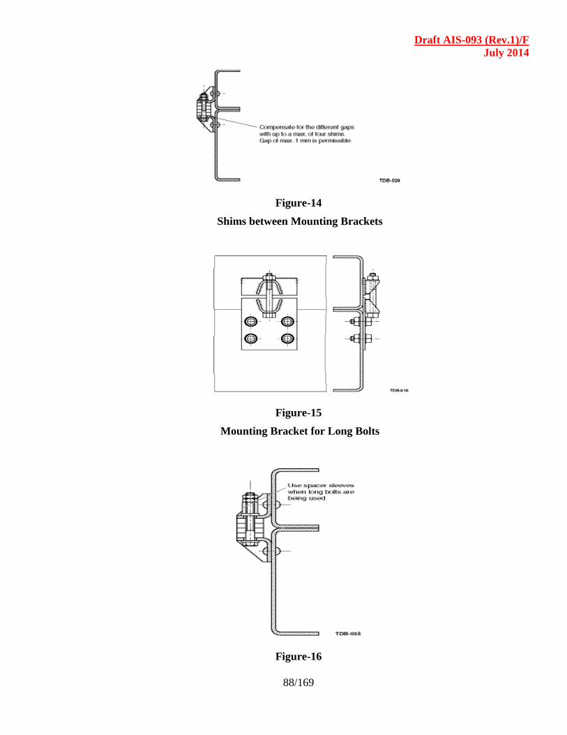
Draft AIS-093 (Rev.1)/F
July 2014
88/169
Figure-14
Shims between Mounting Brackets
Figure-15
Mounting Bracket for Long Bolts
Figure-16
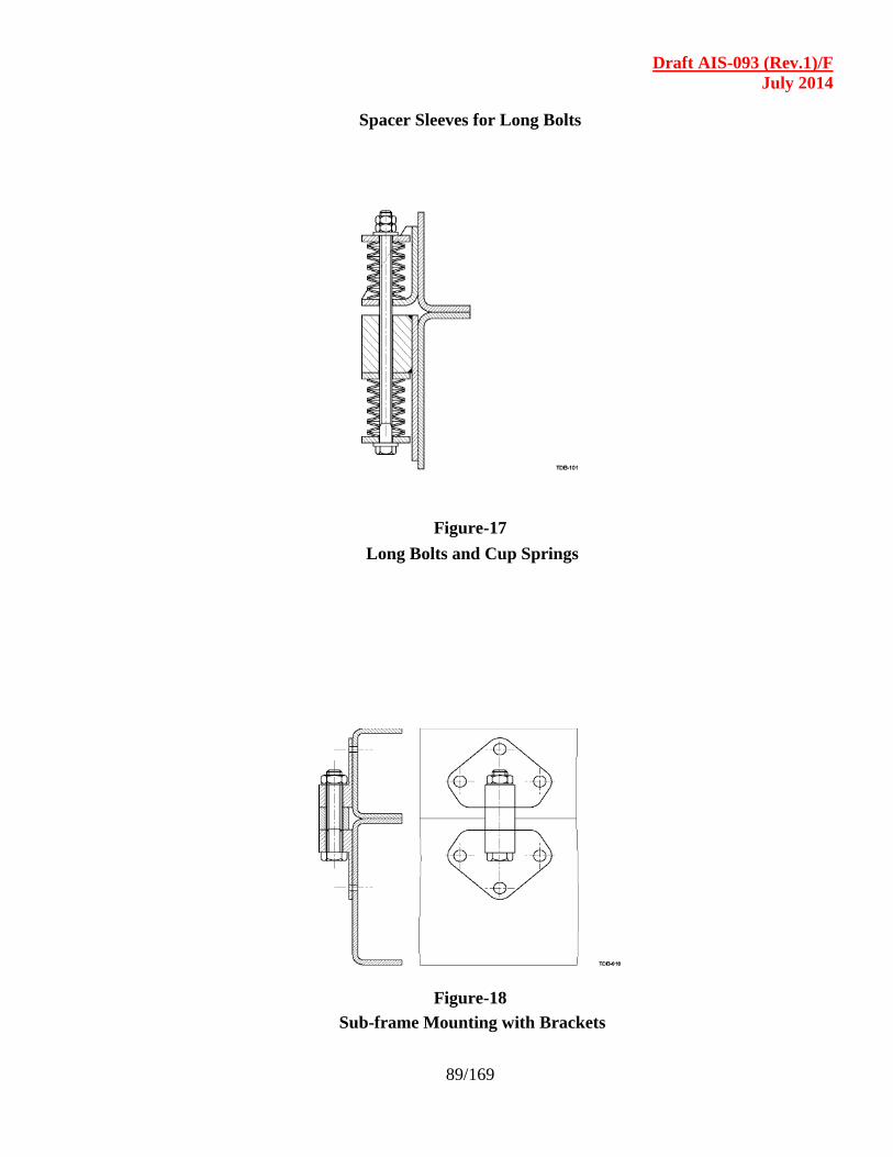
Draft AIS-093 (Rev.1)/F
July 2014
89/169
Spacer Sleeves for Long Bolts
Figure-17
Long Bolts and Cup Springs
Figure-18
Sub-frame Mounting with Brackets
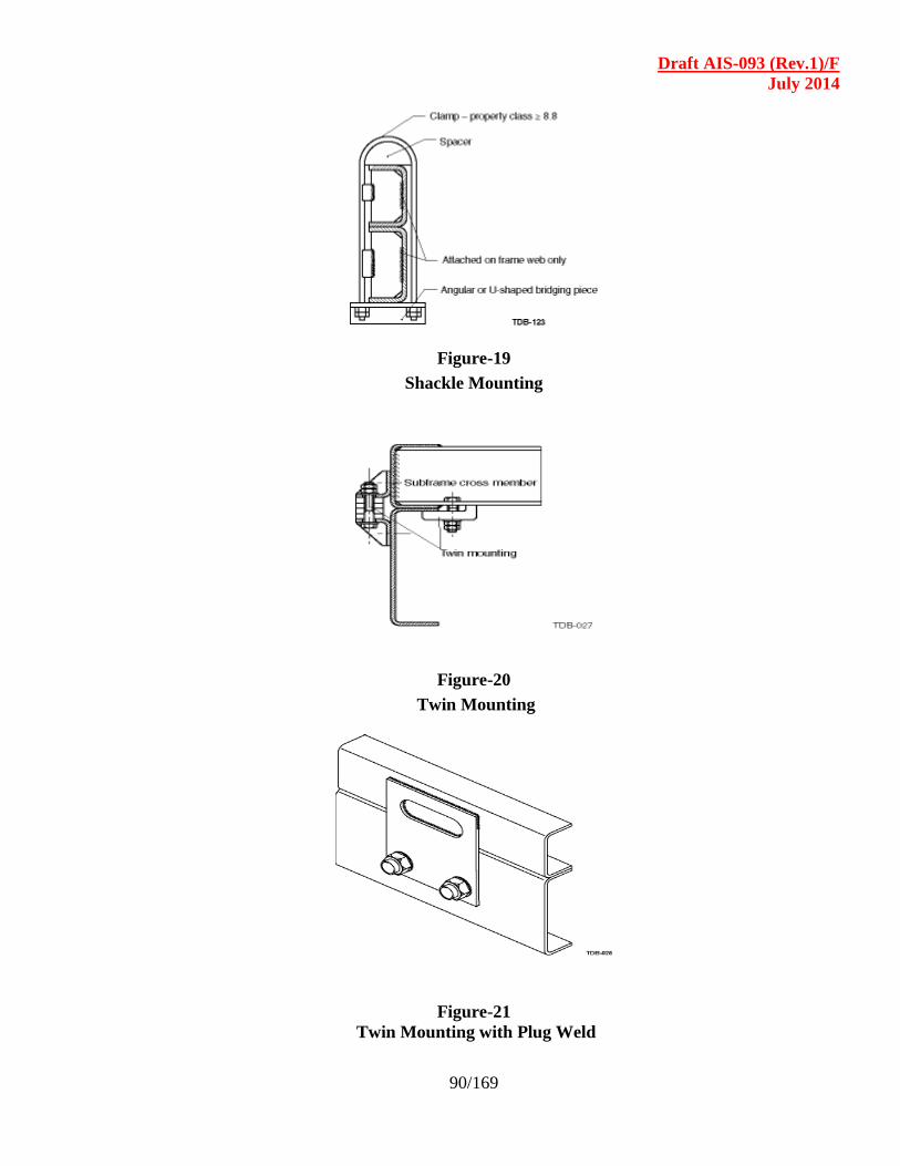
Draft AIS-093 (Rev.1)/F
July 2014
90/169
Figure-19
Shackle Mounting
Figure-20
Twin Mounting
Figure-21
Twin Mounting with Plug Weld
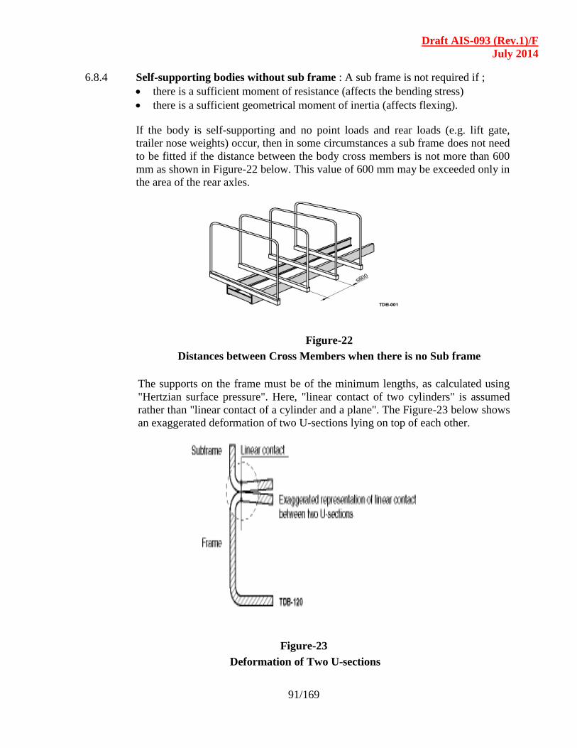
Draft AIS-093 (Rev.1)/F
July 2014
91/169
6.8.4 Self-supporting bodies without sub frame : A sub frame is not required if ;
there is a sufficient moment of resistance (affects the bending stress)
there is a sufficient geometrical moment of inertia (affects flexing).
If the body is self-supporting and no point loads and rear loads (e.g. lift gate,
trailer nose weights) occur, then in some circumstances a sub frame does not need
to be fitted if the distance between the body cross members is not more than 600
mm as shown in Figure-22 below. This value of 600 mm may be exceeded only in
the area of the rear axles.
Figure-22
Distances between Cross Members when there is no Sub frame
The supports on the frame must be of the minimum lengths, as calculated using
"Hertzian surface pressure". Here, "linear contact of two cylinders" is assumed
rather than "linear contact of a cylinder and a plane". The Figure-23 below shows
an exaggerated deformation of two U-sections lying on top of each other.
Figure-23
Deformation of Two U-sections
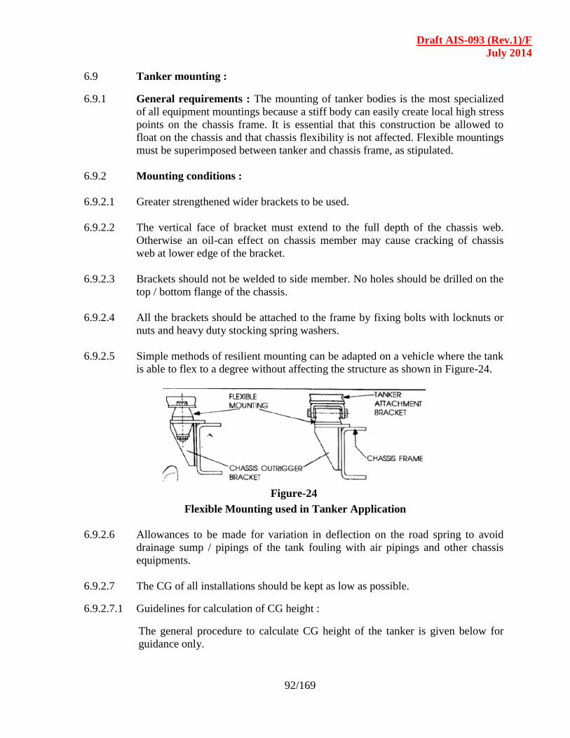
Draft AIS-093 (Rev.1)/F
July 2014
92/169
6.9 Tanker mounting :
6.9.1 General requirements : The mounting of tanker bodies is the most specialized
of all equipment mountings because a stiff body can easily create local high stress
points on the chassis frame. It is essential that this construction be allowed to
float on the chassis and that chassis flexibility is not affected. Flexible mountings
must be superimposed between tanker and chassis frame, as stipulated.
6.9.2 Mounting conditions :
6.9.2.1 Greater strengthened wider brackets to be used.
6.9.2.2 The vertical face of bracket must extend to the full depth of the chassis web.
Otherwise an oil-can effect on chassis member may cause cracking of chassis
web at lower edge of the bracket.
6.9.2.3 Brackets should not be welded to side member. No holes should be drilled on the
top / bottom flange of the chassis.
6.9.2.4 All the brackets should be attached to the frame by fixing bolts with locknuts or
nuts and heavy duty stocking spring washers.
6.9.2.5 Simple methods of resilient mounting can be adapted on a vehicle where the tank
is able to flex to a degree without affecting the structure as shown in Figure-24.
Figure-24
Flexible Mounting used in Tanker Application
6.9.2.6 Allowances to be made for variation in deflection on the road spring to avoid
drainage sump / pipings of the tank fouling with air pipings and other chassis
equipments.
6.9.2.7 The CG of all installations should be kept as low as possible.
6.9.2.7.1 Guidelines for calculation of CG height :
The general procedure to calculate CG height of the tanker is given below for
guidance only.
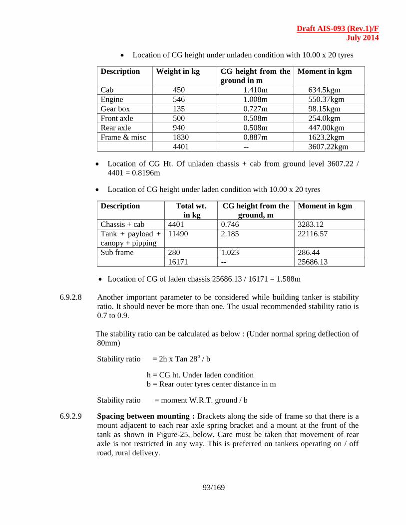
Draft AIS-093 (Rev.1)/F
July 2014
93/169
Location of CG height under unladen condition with 10.00 x 20 tyres
Description Weight in kg CG height from the
ground in m
Moment in kgm
Cab 450 1.410m 634.5kgm
Engine 546 1.008m 550.37kgm
Gear box 135 0.727m 98.15kgm
Front axle 500 0.508m 254.0kgm
Rear axle 940 0.508m 447.00kgm
Frame & misc 1830 0.887m 1623.2kgm
4401 -- 3607.22kgm
Location of CG Ht. Of unladen chassis + cab from ground level 3607.22 /
4401 = 0.8196m
Location of CG height under laden condition with 10.00 x 20 tyres
Description Total wt.
in kg
CG height from the
ground, m
Moment in kgm
Chassis + cab 4401 0.746 3283.12
Tank + payload +
canopy + pipping
11490 2.185 22116.57
Sub frame 280 1.023 286.44
16171 -- 25686.13
Location of CG of laden chassis 25686.13 / 16171 = 1.588m
6.9.2.8 Another important parameter to be considered while building tanker is stability
ratio. It should never be more than one. The usual recommended stability ratio is
0.7 to 0.9.
The stability ratio can be calculated as below : (Under normal spring deflection of
80mm)
Stability ratio = 2h x Tan 28o / b
h = CG ht. Under laden condition
b = Rear outer tyres center distance in m
Stability ratio = moment W.R.T. ground / b
6.9.2.9 Spacing between mounting : Brackets along the side of frame so that there is a
mount adjacent to each rear axle spring bracket and a mount at the front of the
tank as shown in Figure-25, below. Care must be taken that movement of rear
axle is not restricted in any way. This is preferred on tankers operating on / off
road, rural delivery.

Draft AIS-093 (Rev.1)/F
July 2014
94/169
Figure-25
Arrangement of Rear Mounting and Spacing of Mounting
6.9.2.10 A greater relative movement between tank and frame can be achieved by
incorporating coil springs between the tanker mounting feet and the front
mounting brackets as shown in Figure-26.
Figure-26
Arrangement of Front Mounting with Coil Springs
Alternatively, trunnion type of front mounting can also be tried. In this case, rear
most bracket must be fastened rigidly by bolts, giving a positive constraint
between body and chassis during acceleration, road movement, cornering and
braking as shown in Figure-27.

Draft AIS-093 (Rev.1)/F
July 2014
95/169
Figure-27
Preferred Arrangement of Front Mounting with Trunnion
6.9.2.11 Alternatively “U” bolts / fish plates arrangement with full length body runner as
described in the earlier chapter can be fitted as shown in Figure-28. The typical
“U” bolt arrangement for a milk tanker with integral tapered runner is shown in
following Figure-29. In the tanker is to carry inflammable liquids or gases,
petroleum regulations are to be followed. Depending upon the substances being
carried, some of the equipments / points have to be fitted / followed as per
Schedule (iii) of the Petroleum rules 1976, Rules No. 71 of Petroleum Rule 1976
and Rule No. 71 of 1937.
Figure -28
General Method of Tank Mountings

Draft AIS-093 (Rev.1)/F
July 2014
96/169
Figure 29
Typical “U” Bolt Arrangement Fitted on Milk Tanker
Insulated return wiring.
A battery master switch and batteries enclosed inside the cab.
A fire screen.
An exhaust system wholly ahead of firescreen with flame trap or spark
arrester.
Positively retained wired glass or planks for all rear ward facing cab windows.
Fire extinguishers – foam type.
6.9.3 Other requirements for body fixtures and mountings :
Tank and container bodies require a continuous sub frame, yield point s 0.2 > 350
N/mm² .The connection between the body and chassis in the front area must be
designed so that it does not excessively hinder the frame’s ability to twist. This
can be achieved by having front mountings that are as torsionally compliant as
possible, e.g. by having
• Pendulum-type mounting as shown in Figure-30.
• Flexible mounting as shown in Figure-31.

Draft AIS-093 (Rev.1)/F
July 2014
97/169
Figure - 30
Front Mounting as a Pendulum Mounting
Figure - 31
Front Mounting as a Flexible Mounting
The front mounting point should be as close as possible to the front axle center
line as shown in Figure-31 and Figure-32. The rear, laterally stiff body support
must be fitted in the area of the theoretical rear axle center line. There should also
be a sufficiently large connection to the frame at this point. The distance between
the theoretical rear axle center line and the centre of the support must be < 1000
mm as shown in Figure-31 and Figure-32.
6.9.4 Layout of tanker and bulk container mountings : After installing the body it
is important that a check be made to see if vibrations or other disadvantageous
properties are noticeable. Vibration can be influenced with the correct design of
sub frame and the correct layout of the tanker mountings.
6.9.5 Tankers and container bodies without sub-frames : Tanker and container
bodies without sub frames can be approved if the conditions described here are
observed and there are double or triple mountings on each side of the frame. All
supports must be arranged at the specified distances as shown in Figure-32 and
Figure-33. If the permissible range is exceeded, this may cause the frame to
bend excessively, which is not permitted; a continuous sub frame would then be
required as shown in Figure 33. After installing the body it is important that a
check be made to see if vibration or other disadvantageous properties are
noticeable. The Table-7, given below would indicate the details of chassis
without sub-frames for tanker bodies with double and triple mountings. The
mounting arrangement of tankers are also shown in Figure-34 to Figure-37,
which may be taken as general guidelines.
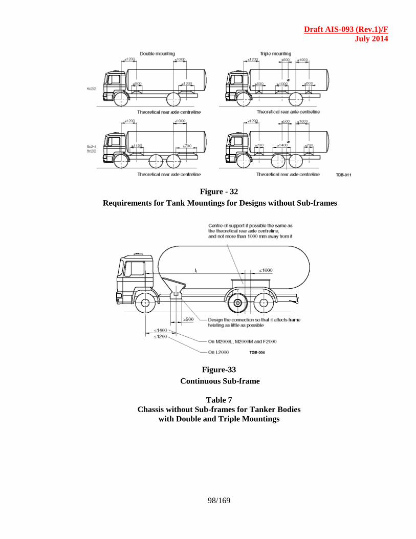
Draft AIS-093 (Rev.1)/F
July 2014
98/169
Figure - 32
Requirements for Tank Mountings for Designs without Sub-frames
Figure-33
Continuous Sub-frame
Table 7
Chassis without Sub-frames for Tanker Bodies
with Double and Triple Mountings
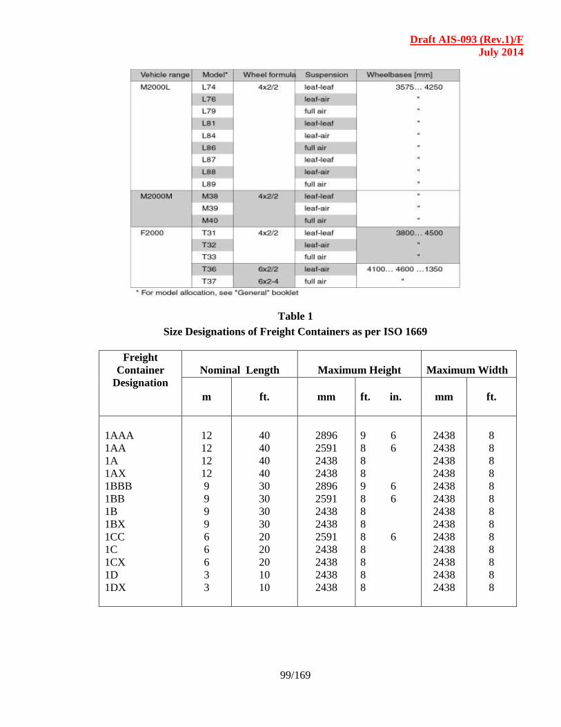
Draft AIS-093 (Rev.1)/F
July 2014
99/169
Table 1
Size Designations of Freight Containers as per ISO 1669
Freight
Container
Designation
Nominal Length
Maximum Height
Maximum Width
m
ft.
mm
ft. in.
mm
ft.
1AAA
1AA
1A
1AX
1BBB
1BB
1B
1BX
1CC
1C
1CX
1D
1DX
12
12
12
12
9
9
9
9
6
6
6
3
3
40
40
40
40
30
30
30
30
20
20
20
10
10
2896
2591
2438
2438
2896
2591
2438
2438
2591
2438
2438
2438
2438
9 6
8 6
8
8
9 6
8 6
8
8
8 6
8
8
8
8
2438
2438
2438
2438
2438
2438
2438
2438
2438
2438
2438
2438
2438
8
8
8
8
8
8
8
8
8
8
8
8
8
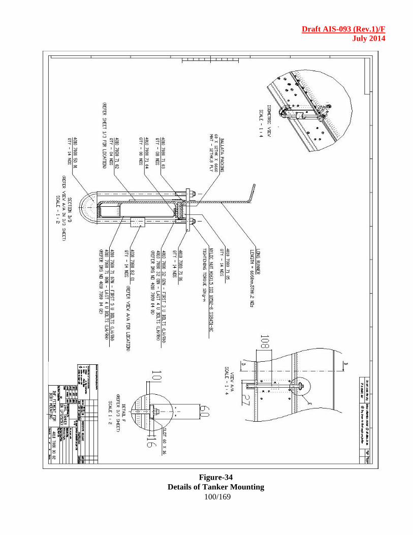
Draft AIS-093 (Rev.1)/F
July 2014
100/169
Figure-34
Details of Tanker Mounting
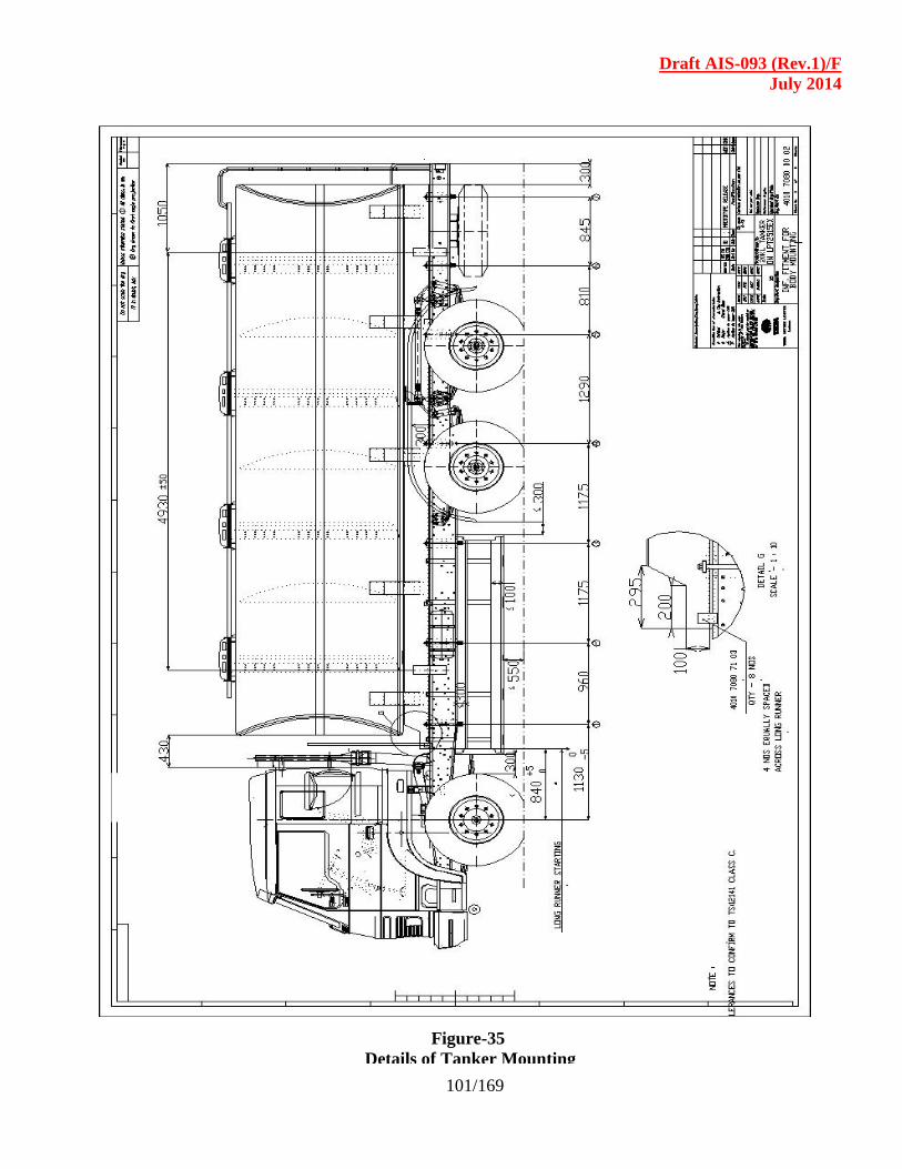
Draft AIS-093 (Rev.1)/F
July 2014
101/169
Figure-35
Details of Tanker Mounting

Draft AIS-093 (Rev.1)/F
July 2014
102/169
Figure-36
Details of Tanker mounting
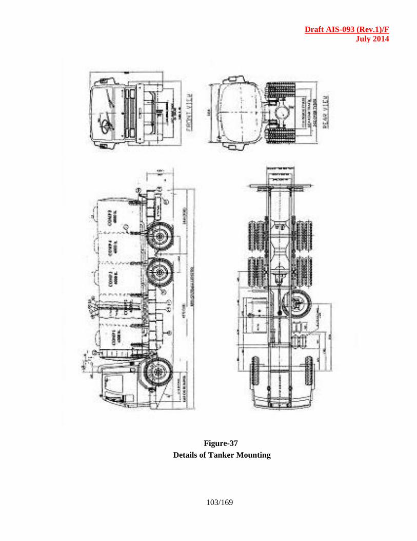
Draft AIS-093 (Rev.1)/F
July 2014
103/169
Figure-37
Details of Tanker Mounting
Draft AIS-093 (Rev.1)/F
July 2014
104/169
SECTION - 7.0
AUTOMOTIVE TRAILERS
LIST OF CONTENTS
7.1 Scope
7.2 Definition
7.3 General Requirements
7.4 Tipping Stability of Heavy Trucks and Trailers
7.5 Electrical System
7.6 Applicable Standards for Trailers
7.7 Service Brakes for Trailers – Constructional and
Functional Requirements
7.8 Compatibility between Tractor and Trailer
7.9 Safety Critical Items
7.10 Interchangeability of Trailers
7.11 Type Approval of Trailers

Draft AIS-093 (Rev.1)/F
July 2014
105/169
7.1 SCOPE : This chapter covers the requirements applicable to semi-trailers and
trailers of category T3 and T4, coupled with trucks of category N, as are defined
in AIS-053. However, the special provisions for carriage of dangerous and
hazardous goods are covered in Section -5 of this code.
7.2 DEFINITIONS : 7.2.1 “T’ category” means towed vehicle with at least two wheels, on account of its
design and appointment is intended for carrying goods or persons. Semi-trailers
are also included in this category.
7.2.2 “Semi-trailer” means a truck trailer equipped with one or more axles, and so
constructed that the front end and a substantial part of its own weight and that of
its load rests upon another vehicle.
7.2.3 “Full trailer” means a truck trailer constructed so that all of its own weight and
that of its load rest upon its own wheels.
7.2.4 “Balanced full trailer” means a truck trailer in which the load carrying axle(s) is
(are) located approximately under the center-line of the cargo body.
7.2.5 “Load-Dividing dolly” is coupled between a truck tractor and semi-trailer to
reduce the load imposed by the semi-trailer on the truck tractor. It is a truck
trailer with one or more axles equipped with a fifth wheel, draw bar, and other
parts necessary for its use.
7.2.6 “Trailer converter dolly” means a truck trailer with one or more axles equipped
with a fifth wheel, a drawbar, and other parts necessary to convert a semi-trailer
to a full trailer.
7.2.7 “Pole trailer” means a truck trailer, without auxiliary motive power, designed to
be drawn by a truck or truck tractor, attached by means of a reach or a pole (or
by being boomed or otherwise secured to the drawing motor vehicle), and
intended for transporting long or irregularly shaped loads such as poles, logs,
pipes, or structural members which are generally capable of sustaining
themselves as beams between supporting connections.
7.2.8 “Low bed trailer” means a trailer with a flat loading platform but with a swan
neck or a wheel arch both at the front and at the rear end. The platform height
may be lower than the trailer tyre diameter.
7.2.9 “Semi low-bed trailer” means a trailer with a flat loading platform but with a
swan neck or wheel arch at the front end. The height of the platform may be
equal to or more than the trailer tyre diameter.
7.2.10 “Double drop frame trailer” means a trailer where the platform between the
wheels is dropped as low as possible to facilitate loading from fitted outboard.
7.2.11 “Single drop frame trailer” means a trailer where the platform is dropped behind
the front wheels for loading either by means of a ramp or other suitable method.
The rear wheels are usually fitted outboard.
Draft AIS-093 (Rev.1)/F
July 2014
106/169
7.2.12 “Flat platform trailers” means a trailer with a flat loading platform without any
swan necks or wheel arches.
7.2.13 “Swan neck (goose neck)” means the raised portion of the trailer beyond the
loading platform generally used to accommodate its own wheels or wheels of
the towing vehicle.
7.2.14 “Wheel arch” means the raised portion on the platform of a trailer provided to
accommodate the vertical travel of its own wheels.
7.2.15 “Tow bar” means strut or column like device temporarily attached between the
rear of a towing vehicle and the front of the vehicle being towed. Its purpose is
to maintain the interval or distance between the two.
7.2.16 “Tow eye” means the trailer part of the mechanical coupling of an independent
trailer, normally attached to the pintle hook of the tractor.
7.2.17 “Towing hook (Pintle hook)” means the tractor part of the mechanical coupling
of an independent trailer normally attached to the tow eye of the trailer.
7.2.18 “Fifth wheel coupling” means a device used to connect a truck tractor to a semi
trailer and to permit articulation between the units. It is generally composed of a
lower half, mounted on the tractor, consisting of a trunnion, plate and latching
mechanism, for connection with a king pin mounted on the semi-trailer.
7.2.19 “King pin” means the trailer part of the mechanical coupling of a transport
tractor-trailer normally attached to fifth wheel of the tractor.
7.2.20 “Towing capacity” towing capacity of the tow bar is equal to the total weight of
the trailer(s) towed.
7.2.21 “Trailer body” means the structure or fixture especially provided to contain or
support the material or property to be transported from one place to other.
7.2.22 “Tandem axles” means any two or two wheel axles spaced by 2440 mm or
more (or as specified under CMV(A)R, 1989) from each other.
7.2.23 “Tandem bogie” means two axle wheels spaced by more than 1300 mm up to
2440mm from each other with defined load sharing ratio.
7.2.24 “Triple axles” means three wheel axles with each axle spaced by more than
3000 mm between each other.
7.2.25 “Tridem bogie” means three axle wheels spaced by 3000 mm or less with
defined load sharing ratio.
7.3 General requirements :
7.3.1 Axle loading : The permissible load on the axles shall be as per the prescribed
limits under the Central Motor Vehicles Rules, 1989.
Draft AIS-093 (Rev.1)/F
July 2014
107/169
7.3.2 Dimensional requirements : The dimensional requirements for trailers shall be
in accordance with Rule 93 of the Central Motor Vehicles Rules, 1989.
7.3.3 External Projections : The requirements for external projections shall be in
accordance with IS :13942, as amended from time to time and as specified at
Sl No. 11 of Table under Rule 124 of the Central Motor Vehicles Rules, 1989.
7.3.4 Rear Under run Protection : The requirements of Rear under run protection shall
be as per IS : 14812, as amended from time to time.
7.3.4.1 Rear under run protective device is not required on:
Vehicles designed with a large clearance above the ground, mainly intended
to be used off road.
Vehicles used by national or municipal fire brigades for salvaging
operations, rescue vehicles, tippers, vehicle with a loose loading platform or
with arrangements for a snow plough, road surfacing machine, a gritting
device.
7.3.5 Lateral Under run Protection : The requirements of lateral under run
protection shall be as per IS:14682, as amended from time to time. Exemptions
for fitment of lateral under run protective devices may be as follows.
7.3.5.1 Fire Tenders and other such vehicles like sideway / 3 way tippers, concrete
mixers etc., where the body work will be incompatible with fitment of such a device.
7.3.5.2 Lateral protection is not however required between tandem or tridem axles if
their mutual distance is less than 2.1 m.
7.3.5.3 Trailers with moveable rear axles need only fulfill the requirements in these
points when the axles are in their forward most position. Extension of the axles must
not produce a gap in the lateral protection.
7.3.5.4 Trailers with moveable rear axles and extendable trailers may have lateral
protection constituted by a strap under the following conditions :
The strap is fitted with either an automatic or a manual tensioning device
which can be tensioned with a torque wrench.
7.3.5.5 Semi-trailers with moveable rear axles need not be fitted with lateral protection
if the distance from a transverse plane through the centre of the coupling pin in
its rearmost position to the centre of the front axle in its most forward position is
less than 3.9 m.
7.4 Tipping Stability of Trailers : Trailers with end-tipping loaded to the total
weight with normal tipping goods, must tip an evenly distributed cargo without
turning over, with the vehicle across an incline and with all the relevant axles
can be proved either by calculation or by physical tests.
7.5 Electrical System :

Draft AIS-093 (Rev.1)/F
July 2014
108/169
7.5.1 Connections between tractor and trailer : The trailer connections and cables
shall conform to the provisions laid down in Section 4 of this code.
7.5.2 Lighting and signaling devices : The lighting and signalling devices provided
on trailers shall conform to Rule 102 to 107, of Central Motor Vehicles Rules,
1989.
7.5.3 Bulbs : The performance requirements of Bulbs shall be as per AIS-034 as
amended from time to time and as specified at Sl No. 1 of the Table under Rule
124 of the Central Motor Vehicles Rules, 1989.
7.5.4 Lighting and signalling systems : Performance requirements for lighting and
signaling devices shall be as per AIS-012 as amended from time to time and as
specified at Sl. No. 20 of the Table under Rule 124 of the Central Motor
Vehicles Rules, 1989.
7.5.5 Installation of light and light-signaling devices : The requirements of
installation of lighting & signaling devices shall be as per AIS-008 as amended
from time to time and as specified at Sl. No. 20 of the Table under Rule 124 of
the Central Motor Vehicles Rules, 1989.
7.5.6 Electrical coupling : Seven conductor electrical coupling between tractor &
trailer shall meet the requirements stated in IS:10393, as amended from time to
time (performance requirements as cross referred under IS :10393, shall be as
per IS : 9895). Other type of electrical coupling, if used shall be in
accordance with relevant IS or ISO or SAE standards.
7.5.7 The guidelines for mounting of electrical connections for truck and trailer may
be drawn from IS :13509, as amended from time to time.
7.6 Applicable standards for trailers :
7.6.1 Test standards : The following standards consolidated below are meant for test
and measurement purpose, are consolidated below for reference at one point.
Sr.
No. Standard Title of the Standard
1 IS: 6763(PT 1):1987 Specification and testing of fifth wheel king pin, Part 1 size
50(first revision)
2 IS:6763(PT 2):1987 Specification and testing of fifth wheel king pin, Part 2 size
90(first revision)
3 IS:7774(PT 1):1975 Glossary of terms relating to transport tractors and trailers. Part
1 basic terms
4 IS:7774(PT 2):1975 Glossary of terms relating to transport tractors and trailers. Part
2 dimensions and weight
5 IS:8007:1976 Dimension of fifth wheel coupling between transport tractor
and semi/articulated trailers for interchangeability
Draft AIS-093 (Rev.1)/F
July 2014
109/169
6 IS:8297:1976 Towing jaw for use between trailers of up to 16 tonnes gross
mass and transport tractor
7 IS:8298:1976 Towing jaw for use between trailers of up to 5 tonnes gross
mass and transport tractor
8 IS:8299:1976 Towing hook for use between trailers of up to 16 tonnes gross
mass and transport tractor
9 IS:8300:1976 Towing hook for use between trailers of up to 35 tonnes gross
mass and transport tractor
10 IS:8752:1978 Towing hook for use between trailers of up to 5 tonnes gross
mass and transport tractor
Sr.
No. Standard Title of the Standard
11 IS:9895:1981 Electrical connection between towing vehicles and trailers- Test
methods and requirements
12 IS:9942:1981 T-Sign plate for trailers
13 IS:10393:1982 Specification for electrical connector for tractor trailers jumper
cable
14 IS:10752:1983 Dimension and testing requirement of landing gears for
mounting on semi-trailers
15 IS:10792:1984 Testing and acceptance criteria of pneumatic coupling between
tractors and trailers
16 IS:12807:1989 Specification for drawbar eyes for mechanical connections
between towing vehicles and trailers
17 IS:13284:1992 Automotive vehicle-Drawbar coupling and hinged drawbar-
method of test for strength
18 IS:11852
(Part 1):2001
Automotive vehicles-Brake and braking system: Part 1 -
Terminology (first revision)
19 IS:11852
(Part 2):2001
Automotive vehicles-Brake and braking system: Part 2 -
General function and features (first revision)
20 IS:11852
(Part 3):2001
Automotive vehicles-Brake and braking system: Part 3 -
Performance requirements and evaluation (first revision)
21 IS:11852
(part 4):2001
Automotive vehicles-Brake and braking system: Part 4 -
Compressed air and air assisted brakes special requirement
(first revision)
22 IS:11852
(part 5):2001
Automotive vehicles-Brake and braking system: Part 5 -
Compressed air and air assisted brakes pressure test
connections (first revision)
23 IS:11852
(part 6):2001
Automotive vehicles-Brake and braking system: Part 6 -
Vacuum braking systems- Special requirements (first revision)
24 IS:11852
(part 7):2001
Automotive vehicles-Brake and braking system: Part 7 - Inertia
dynamometer test method for brake linings
25 IS:11852
(part 8):2001
Automotive vehicles-Brake and braking system: Part 8 - Test
procedures (first revision)
26 IS:13942:1994 Automotive vehicles-External projections- Performance
requirements

Draft AIS-093 (Rev.1)/F
July 2014
110/169
27 IS:14682:1999 Automotive vehicles-lateral protection (side guards)-Technical
requirements
28 IS:14812:2000 Automotive vehicles-Rear under run protection device-General
Requirements
29 IS:12222:1987 Method of measurement of turning circle of automotive vehicle
30 IS:10792:1984 Testing and acceptance criteria of pneumatic coupling between
tractors and trailers
31 IS:15101:2002 Transport tractors and trailers – Fifth wheel coupling strength
tests
7.6.2 Guideline standards : The following standards consolidated below are meant for general
guideline purpose , are consolidated below for reference at one point..
Sr. No Standard Title of the Standard
1 IS:8037:1976 General requirement for transport tractors-trailers
2 IS:8274:1976 Drawbar eyes and fore carriage pins for connection between
trailers of up to 35 tonnes gross mass and transport tractor
3 IS:8903:1978 Specification for drawbars the trailers of up to 5 tonnes
gross mass
4 IS:9760:1981 Dimensions for coupling arrangement between towing vehicle
and trailer
5 IS:9905:1981 Pneumatic coupling between tractors and trailers
6 IS:10766:1983 Mounting dimension for fifth-wheel coupling
7 IS:12358:1988 Dimension for contact type coupling for vacuum and pressure
braking system on trailers and semi-trailers
8 IS:13544:1992 Trailers-mounting of ball bearing turn table-Dimensions
9 IS:13579:1992 Transport trailers-Method of test
10 IS:14880:2000 Trailers-Drawbars coupling and eye for rigid drawbar-method of
strength test
11 IS:13460:1992 Automotive vehicles-Electrical connections between towing
vehicles and trailers with 6 or 12 V electrical equipment-
Type 12 S (supplementary)
12 IS:13461:1992 Automotive vehicles-Electrical connections between towing
vehicles and trailers with 6 or 12 V electrical equipment-
Type 12 S (Normal)
13 IS:13491:1992 Automotive vehicles-Electrical connections between towing
vehicles and towed vehicles with 24 V electrical equipment-
Type 24 S (Normal)
Draft AIS-093 (Rev.1)/F
July 2014
111/169
14 IS:13499:1992 Automotive vehicles-Electrical connections between towing
vehicles and trailers with 24 V electrical equipment-
Type 24 S (Normal)
15 IS:13509:1992 Automotive vehicles-Towing vehicles-Mounting of electrical
connections on rear cross members
7.7 Service Brakes for Trailers – Constructional and Functional requirements :
7.7.1 The service brake must work on all wheels of the vehicle.
7.7.2 Brake pipes must be designed and positioned that corrosion is avoided as much as
possible.
7.7.3 Brake pipes made of plastic used in compressed air or vacuum systems must be
strong and durable. This shall comply with the requirements stated in BIS Doc. TED
13 (266). The finalised Indian Standard on this subject by TED-13 may then be
referred.
7.7.4 The requirement regarding strength and durability is regarded as having been met if
the plastic brake pipes meet the requirements in DIN 74324 (July 1987) or SAE
J8444 as amended from time to time.
7.7.5 A brake that is connected to the brake system of the towing vehicle shall be such that
the connection does not detrimentally affect the brake system of the towing vehicle.
A hydraulic trailer brake may only be connected to the hydraulic system of the towing
vehicle in combination with a vacuum unit or similar, such that the brake fluid in the
brake system of the towing vehicle is only used for governing the vacuum unit or
similar and where the hydraulic system of the governing unit is separated from the
rest of the hydraulic system.
7.7.6 In a service brake, the operation of which is dependent on stored power, the storage
containers shall have a total volume that is at least eight times, but no more than
twelve times as large as the combined swept volume of the brake cylinders, using
two-thirds of the maximum movement of the piston rod or similar.
7.7.7 The vacuum and compressed air system shall be connected to the towing vehicle by
means of two lines, one feed line and one operating line.
7.7.8 The brake system shall comply to Central Motor Vehicle Rules, 1989 requirements
stated vide IS : 11852 as amended from time to time or other standard as amended
from time to time notified under Rule 96 of the Central Motor Vehicles Rules, 1989.
7.7.9 Further reference to be made with SAE J 702 as amended from time to time for
location of hose connection. This is indicative and may be used as a guideline only.
Figure -1 and Figure - 2 may be referred.
7.7.10 Brake palm couplings shall meet the requirement of IS :9905 for dimensions.
The performance shall be as per IS:10792. If any other type of advanced coupling
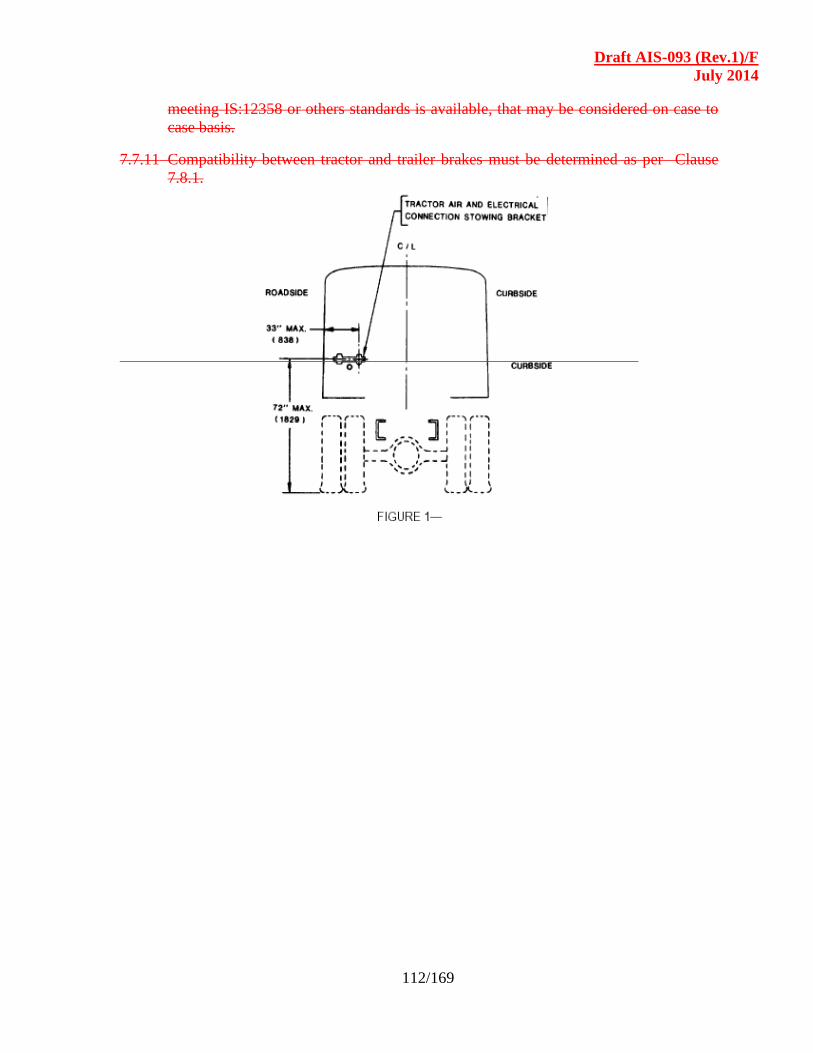
Draft AIS-093 (Rev.1)/F
July 2014
112/169
meeting IS:12358 or others standards is available, that may be considered on case to
case basis.
7.7.11 Compatibility between tractor and trailer brakes must be determined as per Clause
7.8.1.
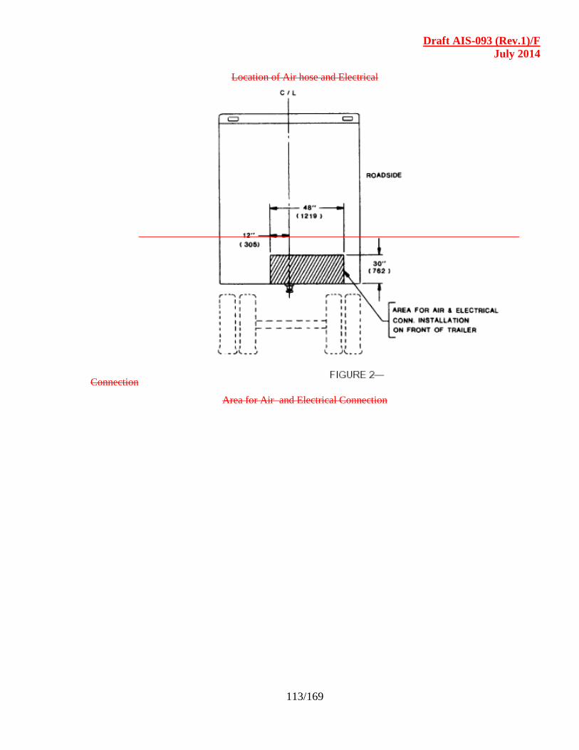
Draft AIS-093 (Rev.1)/F
July 2014
113/169
Location of Air hose and Electrical
Connection
Area for Air and Electrical Connection

Draft AIS-093 (Rev.1)/F
July 2014
114/169
7.8 Compatibility between tractor and trailer :
7.8.1 Brake system compatibility : The requirements of braking shall be as per
IS : 11852 as amended from time to time including that of brake adhesion
utilisation for trailer axles.
7.8.1.1 Guidelines for calculating the trailer brake system requirements-An
illustrative example
The Actual Brake Force values can be arrived from the Sample
Calculation, shown below.
Actual Brake Force on Tractor Force available at the tractor
wheels
Actual Brake Force on Trailer Force available at the trailer
wheels Total Actual Brake Force Sum of tractor and trailer
forces
Details required to find out the Brake Forces on Trailer :
Tyre Size / Rolling Radius.
Brake Drum diameter.
Brake Chamber Type. (Eg: 20 or 24 or 30)
Pressure at Brake Chamber.
Brake Lever Length / Slack Adjuster Length.
Brake Cam’s Radius.
Gross Trailer weight with Load Distribution at King Pin and
Trailer Axles.
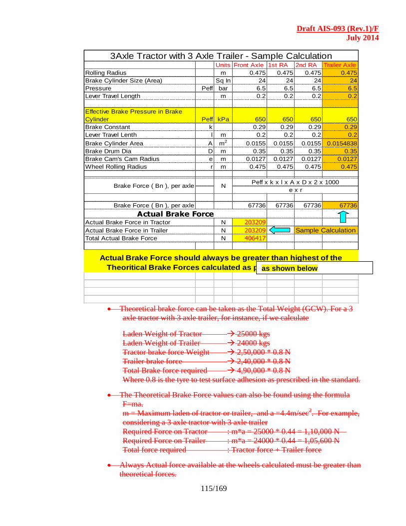
Draft AIS-093 (Rev.1)/F
July 2014
115/169
Units Front Axle 1st RA 2nd RA Trailer Axle
Rolling Radius m 0.475 0.475 0.475 0.475
Brake Cylinder Size (Area) Sq In 24 24 24 24
Pressure Peff bar 6.5 6.5 6.5 6.5
Lever Travel Length m 0.2 0.2 0.2 0.2
Effective Brake Pressure in Brake
Cylinder Peff kPa 650 650 650 650
Brake Constant k 0.29 0.29 0.29 0.29
Lever Travel Lenth l m 0.2 0.2 0.2 0.2
Brake Cylinder Area A m2 0.0155 0.0155 0.0155 0.0154838
Brake Drum Dia D m 0.35 0.35 0.35 0.35
Brake Cam's Cam Radius e m 0.0127 0.0127 0.0127 0.0127
Wheel Rolling Radius r m 0.475 0.475 0.475 0.475
Brake Force ( Bn ), per axle 67736 67736 67736 67736
N 203209
N 203209 Sample Calculation
N 406417
Actual Brake Force
Actual Brake Force should always be greater than highest of the
Theoritical Brake Forces calculated as per clause 3.2 and 3.3
Total Actual Brake Force
Actual Brake Force in Tractor
Actual Brake Force in Trailer
3Axle Tractor with 3 Axle Trailer - Sample Calculation
Brake Force ( Bn ), per axle NPeff x k x l x A x D x 2 x 1000
e x r
Theoretical brake force can be taken as the Total Weight (GCW). For a 3
axle tractor with 3 axle trailer, for instance, if we calculate
Laden Weight of Tractor 25000 kgs
Laden Weight of Trailer 24000 kgs
Tractor brake force Weight 2,50,000 * 0.8 N
Trailer brake force 2,40,000 * 0.8 N
Total Brake force required 4,90,000 * 0.8 N
Where 0.8 is the tyre to test surface adhesion as prescribed in the standard.
The Theoretical Brake Force values can also be found using the formula
F=ma.
m = Maximum laden of tractor or trailer, and a =4.4m/sec2. For example,
considering a 3 axle tractor with 3 axle trailer
Required Force on Tractor : m*a = 25000 * 0.44 = 1,10,000 N
Required Force on Trailer : m*a = 24000 * 0.44 = 1,05,600 N
Total force required : Tractor force + Trailer force
Always Actual force available at the wheels calculated must be greater than
theoretical forces.
as shown below
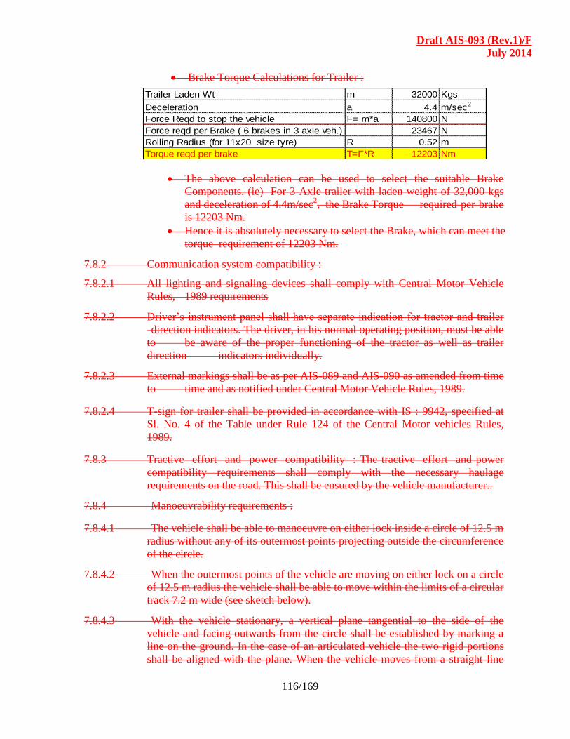
Draft AIS-093 (Rev.1)/F
July 2014
116/169
Brake Torque Calculations for Trailer :
Trailer Laden Wt m 32000 Kgs
Deceleration a 4.4 m/sec2
Force Reqd to stop the vehicle F= m*a 140800 N
Force reqd per Brake ( 6 brakes in 3 axle veh.) 23467 N
Rolling Radius (for 11x20 size tyre) R 0.52 m
Torque reqd per brake T=F*R 12203 Nm
The above calculation can be used to select the suitable Brake
Components. (ie) For 3 Axle trailer with laden weight of 32,000 kgs
and deceleration of 4.4m/sec2, the Brake Torque required per brake
is 12203 Nm.
Hence it is absolutely necessary to select the Brake, which can meet the
torque requirement of 12203 Nm.
7.8.2 Communication system compatibility :
7.8.2.1 All lighting and signaling devices shall comply with Central Motor Vehicle
Rules, 1989 requirements
7.8.2.2 Driver’s instrument panel shall have separate indication for tractor and trailer
direction indicators. The driver, in his normal operating position, must be able
to be aware of the proper functioning of the tractor as well as trailer
direction indicators individually.
7.8.2.3 External markings shall be as per AIS-089 and AIS-090 as amended from time
to time and as notified under Central Motor Vehicle Rules, 1989.
7.8.2.4 T-sign for trailer shall be provided in accordance with IS : 9942, specified at
Sl. No. 4 of the Table under Rule 124 of the Central Motor vehicles Rules,
1989.
7.8.3 Tractive effort and power compatibility : The tractive effort and power
compatibility requirements shall comply with the necessary haulage
requirements on the road. This shall be ensured by the vehicle manufacturer..
7.8.4 Manoeuvrability requirements :
7.8.4.1 The vehicle shall be able to manoeuvre on either lock inside a circle of 12.5 m
radius without any of its outermost points projecting outside the circumference
of the circle.
7.8.4.2 When the outermost points of the vehicle are moving on either lock on a circle
of 12.5 m radius the vehicle shall be able to move within the limits of a circular
track 7.2 m wide (see sketch below).
7.8.4.3 With the vehicle stationary, a vertical plane tangential to the side of the
vehicle and facing outwards from the circle shall be established by marking a
line on the ground. In the case of an articulated vehicle the two rigid portions
shall be aligned with the plane. When the vehicle moves from a straight line

Draft AIS-093 (Rev.1)/F
July 2014
117/169
approach into the circular area described in the sketch below. No part of it shall
move outside of this vertical plane by more than 1.2 m (Refer Figure-3 below).
7.8.4.4 In the case of a vehicle fitted with an axle unloading device, these
requirements shall in each case be fulfilled with the axle in the most
unfavourable condition.
Figure-3
Vehicle Manoeuvrability
7.8.4 .5 Alternate method : Alternately the Turning Circle Diameter of the
combination may be theoretically established adopting the method narrated in
SAE J 695 as amended from time to time. This may be used for approving a
tractor with various trailers and vice versa without physically measuring.
7.9 Safety Critical Items : These are components / parts that are critical to safe
operation of the vehicle and combination. The following components /
systems are identified as critical to the safety of the vehicle. Only certified
items as per relevant Indian Standards shall be used in the trailer.
7.9.1 Fifth Wheel coupling : The fifth wheel coupling provided on the tractor shall
comply with the requirements of IS: 15101 as amended from time to time.
Besides IS:10766 may also be referred as a guideline standard for mounting of
the fifth wheel coupling.
7.9.2 Fifth Wheel king pin : The specifications and other requirements for fifth
wheel king pin shall comply with IS:6763 (Part 1 & 2).
Draft AIS-093 (Rev.1)/F
July 2014
118/169
7.9.3 Draw bar and Draw bar Coupling : The draw bar and draw bar coupling shall
comply with the requirements specified in IS :13284 as amended from time to
time.
7.9.4 Landing gears : To comply with requirements stated in IS :10752 as amended
from time to time.
7.9.5 Tow hook : To comply with requirements stated in IS: 8299, IS: 8300 & IS :
8752 as amended from time to time.
7.9.6 Draw bar coupling : Guidelines may be drawn for IS :8274 for trailers above 5
ton Gross mass. For trailers of less than 5 ton Gross mass, guidelines may be
drawn from IS : 8903 as amended from time to time.
7.9.7 Towing jaw : The towing jaw shall comply with requirements stated in IS : 8297
and IS :8298 as amended from time to time.
7.9.8 Draw bar couplings : The dimensions of draw bar couplings for
interchangeability may be referred to IS : 9760 as guidelines.
7.9.9 Draw bar eye : The draw bar eye shall meet the requirements of IS : 12807 for
dimensions and IS :13284 for performance. However for centre axle trailers, the
requirements shall be as per IS :14880.
7.9.10 Wheel rims and wheel nuts : Wheel rims and wheel nuts used on the trailer shall
meet the requirements of Sl. N0. 8 and Sl. No. 14 of table under Rule 124 of the
Central Motor Vehicles Rules, 1989 respectively.
7.9.11 Tyres : The tyres fitted on semi-trailers and trailers shall comply with the
requirements specified under Rule 95 of Central Motor Vehicles Rules, 1989.
7.10 Interchangeability of trailers : The interchangeability between tractors and
trailers shall be ensured by verifying compliance to IS: 8007 as amended from
time to time.
7.11 Type approval for trailers :
7.11.1 The trailer manufacturers shall have their prototype model of trailer approved
from any of the test agencies referred in Rule 126 of Central Motor Vehicle
Rules, 1989.
7.11.2 The trailer manufacturer shall submit the necessary technical details of the
trailers to the test agencies as per Annexure – III of this Code. Other necessary
details regarding compliance to the relevant Indian Standards for the safety
critical components shall also be submitted to the testing agencies.
Draft AIS-093 (Rev.1)/F
July 2014
119/169
7.11.3 The type approval shall be offered by the testing agencies after necessary
compliance to the requirements stated in this section.
SECTION - 7.0
WORKING STABILITY OF VEHICLES MEANT FOR
CARRIAGE OF HAZARDOUS GOODS
LIST OF CONTENTS
7.1 Terms and Definitions
7.2 Application for Approval
7.3 Approval
7.4 Approval Tests and Specifications.
7.5 Stability Criteria
7.6 Modification of the Vehicle Type and Extension of Approval
ANNEXURES
Annexure - 1 Roll Over Stability / Tilt Table Test Procedure
Annexure - 2 Lateral Stability Calculation
Annexure - 3 Model Calculation Report

Draft AIS-093 (Rev.1)/F
July 2014
120/169
7.1 TERMS AND DEFINITIONS :
For reference in this chapter :
7.1.1 "Approval of a vehicle" means approval of a vehicle type with regard to
rollover stability.
7.1.2 "Vehicle type" means a category of vehicle, which does not differ in such
essential respects as:
Vehicle category, (as per IS :14272) and type (truck, prime mover/tractor,
full trailer, semi-trailer, centre-axle trailer etc)
Maximum mass
Cross-section profile of the tank (circular, elliptical, maxi-volume)
Maximum height of the centre of gravity of the unladen vehicle
Distribution of mass among the axles (including fifth wheel)
Number and arrangement of the axles (including axle spacing)
Suspension arrangements in relation to roll characteristics
Tyre size and structure (radial ply, diagonal ply or bias belted)
Track width
Wheel base
7.1.3 "Laden vehicle" except where otherwise stated, means a vehicle so laden as to
attain its "maximum mass".
7.1.4 "Maximum mass" means the technically permissible maximum mass stated by
the vehicle manufacturer.
7.1.5 "The distribution of mass among the axles" means the proportion of the
maximum permissible mass borne by each axle, as declared by the vehicle
manufacturer.
7.1.6 "Suspension trim height" means the distance between the wheel centre and a
fixed point on the chassis as declared by the vehicle manufacturer.
7.2 Application for approval :
The type approval application shall be accompanied by the following.
7.2.1 The application for approval of a vehicle type with regard to rollover stability shall
be submitted by the vehicle manufacturer / body builder or his duly accredited
representative.
7.2.2 A detailed description of the vehicle type with regard to the items specified
Classes.
7.2.3 Photographs and/or diagrams and drawings of the vehicle showing the vehicle
type in front, side, and rear elevation
7.2.4 Particulars of the vehicle's mass.
Draft AIS-093 (Rev.1)/F
July 2014
121/169
7.2.5 A vehicle, representative of the vehicle type to be approved, shall be submitted to
the Technical Service conducting the approval tests.
7.3 Approval :
7.3.1 If the vehicle type submitted for approval pursuant to this Regulation meets the
requirements of Paragraph 8.4 below, approval of that vehicle type shall be granted
by the authorized test agencies.
7.4 Approval Test and Specifications :
7.4.1 The vehicle shall undergo a tilt table test in accordance with Annexure-1 to this
section, which simulates a non-vibratory steady-state turn. As an alternative a
calculation method in accordance with Annexure-2 to this section may be used to
prove the stability. If there is any doubt or dispute a tilt table test shall be used.
7.4.2 The result of the tilt table test or the calculation method shall be considered
satisfactory if the conditions set out in Paragraphs 8.5 below are satisfied.
7.5 Stability Criteria :
7.5.1 The criteria, using the corresponding Annexure-1 or Annexure-2, must fulfill one
of the following conditions, subject to Paragraph 8.5.1.2.
7. 5.1.1 Tilt table test: Tilt table test: The static rollover stability of the vehicle shall be
such that the point at which overturning occurs would not be passed if a tilt table
angle of 23° has been reached for all tests in both tilt directions. If the vehicle fails
in one of the three tests for a specific direction (right or left), it is allowed to do
one consecutive (re) test.
The static rollover stability of the vehicle is considered to be passed, if overturning
does not occur up to the tilt table angle of 23° for all tests in both (Left & Right)
tilt directions. One consecutive retest is allowed if the vehicle fails in one of the
three tests for a specific direction.
7. 5.1.2 Calculation method: The rollover stability of the vehicle shall be such that the
point at which overturning occurs would not be passed if a lateral acceleration of 4
m/s2 has been reached.
7. 5.1.3 Particular requirements : No contact between parts of the vehicle shall occur
which are not intended to come into contact during normal use.
7.6 Modification of the Vehicle Type and Extension of Approval : Every
modification which affects the vehicle type as defined in Paragraph 8.1 above (for
instance the chassis, body, suspension, axle configuration, etc.) shall be notified to
the approving agency which approved the vehicle type. The agency may then
either:
Draft AIS-093 (Rev.1)/F
July 2014
122/169
Consider that the modifications made are unlikely to have an appreciable
adverse effect and that in any case the vehicle still complies with the
requirements, or
Require a further test report from the Technical Service responsible for
conducting the tests.
Draft AIS-093 (Rev.1)/F
July 2014
123/169
Annexures to Section 7.0
Annexure - 1 of Section 7.0 :
ROLL OVER STABILITY / TILT TABLE TEST PROCEDURE
"Rollover threshold" means the instant when all the wheels on one side of the vehicle have
lost contact with the tilt table surface.
A. General conditions :
A 1. The Tilt Table
A rigid surface should be used. The tyres may rest against a safety block or step
during the test to prevent sideways slipping, provided that the safety block does not
influence the test result.
A2. Wind Conditions
If the tilt table test rig is placed outside, the lateral wind velocity shall not exceed
3 m/s and the total wind velocity shall not exceed 5 m/s.
A3. Tyres
The tyres shall be inflated to pressures as specified by the vehicle manufacturer for
the test vehicle at the laden condition. The tolerance for the inflation pressure in a
cold state is ± 2 %.
A4. Operating Components
A.4.1. All operating components likely to influence the results of this test (e.g. condition
and setting of springs and other suspension components and suspension geometry)
shall be as specified by the manufacturer.
A.4.2. Height-leveling systems should be deactivated (held at static values) during the actual
tilt to avoid inflation/deflation of suspension during the tilt. Cross-coupling from
side to side may need to be deactivated. An exception can be made for levelling
systems with very short response time of less than one second.
B. Measuring accuracy :
The tilt table angle shall be measured with an accuracy of better than 0.3°.
C. Non power-driven vehicles :
C.1. If the vehicle is a centre-axle trailer, the vehicle may be tested with a power-driven
vehicle. Any power-driven vehicle, substitute or support which has the appropriate
coupling system and height may be used, as this will not influence the results.
C.2. If the vehicle is a semi-trailer, the vehicle shall be tested with a tractor or a substitute.
The tractor/substitute will influence the results and therefore a [reference
tractor/substitute] shall be used.
Draft AIS-093 (Rev.1)/F
July 2014
124/169
D. Vehicle loading condition :
The standard test condition is the maximum loaded condition; the laden vehicle. In
this maximum loading condition, the tank vehicle shall be fully loaded, without
exceeding the maximum authorised mass and maximum authorised axle loads.
If the normal load to be carried by the tank vehicle is classified as being of a
dangerous type, it may be replaced by water or another non-dangerous test load. If
the standard test conditions, (a) fully laden or (b) maximum mass, cannot be fulfilled
with this test load then:
(a) a filling factor of the tank between 100% and 70% is acceptable. If at the minimum
filling factor of 70% the total mass and/or axle loads still exceed the maximum
authorised mass and maximum authorised axle loads, a test load with a lower
density shall be used. The distribution of mass of the tank (including the test load)
among the axles shall be proportional to the maximum loaded condition. Tanks
provided with compartments shall be differentially loaded so that the centre of
gravity height at each axle or axle group is as close as possible to the real centre of
gravity height.
(b) a calculation shall be issued by the vehicle manufacturer (1) to provide a new
required maximum tilt table angle for the lighter test load.
E. Safety :
Restraints shall be used to prevent final rollover but these shall be arranged so as not
to interfere with the test.
F. Test procedure :
This procedure consists of a very gradual increase in the tilt table angle up to the
required maximum angle or the rollover threshold. The vehicle shall be tested with all
units in a straight line parallel to the tilt table axis such that no axle longitudinal
centre line is off line by more than 25 mm. All steerable axles of the vehicle shall be
locked to prevent axle lateral movement and/or turning of the wheels in a steering
direction. Also the vehicle shall be fixed in the longitudinal direction to prevent
forward and rearward movement, provided that the method of fixing does not
influence the test result. The vehicle shall be tilted at very low rates of 0.25 °/s or less.
The vehicle shall be gradually tilted three times each to the right and left of the
vehicle longitudinal centre line. Due to the influences of stick-slip in the vehicle's
suspension systems and coupling components, the vehicle shall be removed from the
table between the tests and driven around to "randomise" and "equalise" the
influences of stick-slip and hysteresis.
The vehicle shall be aligned with all units in a straight line parallel to the tilt table axis such that no axle longitudinal centre line is off line by more than 25 mm. The vehicle shall be fixed in the longitudinal direction to prevent forward and rearward movement, provided that the method of fixing does not influence the test result. All steerable axles of the
Draft AIS-093 (Rev.1)/F
July 2014
125/169
vehicle shall be locked to prevent axle lateral movement and/or turning of the wheels in a steering direction. The vehicle shall be tilted at very low rates of 0.25 °/s or less. This procedure consists of a very gradual increase in the tilt table angle up to the required maximum angle or the rollover threshold. The vehicle shall be gradually tilted three times each to the right and left of the vehicle longitudinal centre line. Due to the influences of stick-slip in the vehicle's suspension systems and coupling components, the vehicle shall be removed from the table between the tests and driven around to "randomise" and "equalise" the influences of stick-slip and hysteresis.
Draft AIS-093 (Rev.1)/F
July 2014
126/169
Annexure - 2 of Section 7.0
LATERAL STABILITY CALCULATION
A. General :
The lateral stability of tank vehicles is calculated by simulation of a steady state
circular test (constant radius, constant speed and consequently constant lateral
acceleration). The calculation method take into account the main factors which
influence the stability, such as the height of the centre of gravity, the track width and
all factors which result in a lateral shift of the centre of gravity (axle roll stiffness,
suspension roll stiffness, etc.). In case of semi-trailers the tractor will be simulated
with a reference kingpin roll stiffness.
The specifications of the calculation method are:
1. axle roll centre is at ground level;
2. vehicle structure is assumed to be rigid;
3. vehicle is symmetrical about its center line;
4. tyre and suspension deflections are linear;
5. lateral deflection of suspensions is zero.
B. Definitions :
For the purposes of this calculation:
"Bogie" means an axle group with compensatory load distribution, in which zero load
is attained on all wheels on a given side simultaneously.
C. Symbols (See also Figure 1 below) :
i (-) = axle/bogie index
( i = 1 - n, front to - axle/bogie;
i = T, all axles/bogies;
i = M, stiffest axle/bogie; and
for semi-trailers only i = K, kingpin)
mi = nominal suspension roll axis height
Ai (kN) = axle/bogie load
CDGi (kNm/rad) = suspension roll stiffness at axle roll axis
CDGMi (kNm/rad) = equivalent suspension roll stiffness at ground level
CDRi (kNm/rad) = axle/bogie roll stiffness
CDRESi (kNm/rad) = resolved combined suspension roll stiffness at ground level
FRVi (kN/m) = vertical tyre rate for each axle/bogie
(inclusive the double effect of twin tyres)
Ui (kN) = unsprung weight
Draft AIS-093 (Rev.1)/F
July 2014
127/169
TNi (m) = nominal track width
Ti (m) = theoretical track width for axle/bogie with twin tyres
FE (-) = effective mass factor of stiffest axle/bogie
HG (m) = centre of gravity height of complete vehicle
HN (m) = centre of gravity height of sprung mass
MA (m) = twin tyre width
qc g = corrected lateral acceleration at overturn
qM g = lateral acceleration at first wheel lift
qT g = maximum optimal lateral acceleration at overturn
g (m/s2) = acceleration due to gravity;
g = 9.81 m/s2
èi (rad) = vehicle pseudo-roll angle at wheel lift
ß (deg) = equivalent tilt table angle

Draft AIS-093 (Rev.1)/F
July 2014
128/169
D. General conditions :
Height-leveling systems are not taken into account (held at static values).
E. Trailers :
E1. If the trailer is a full trailer or a central axle trailer the calculation does not have to
include the coupling with the towing vehicle.
E2. If the trailer is a semi-trailer, the tractor will be simulated with a reference
kingpin roll stiffness, which represents the tractor suspension, tyres, chassis & fifth
wheel flexibility at ground level.
F. Vehicle loading condition :
The test condition is the maximum loaded condition; laden vehicle. In this maximum
loading condition, the tank vehicle shall be fully loaded, without exceeding the
maximum
authorized mass and maximum authorised wheel loads.
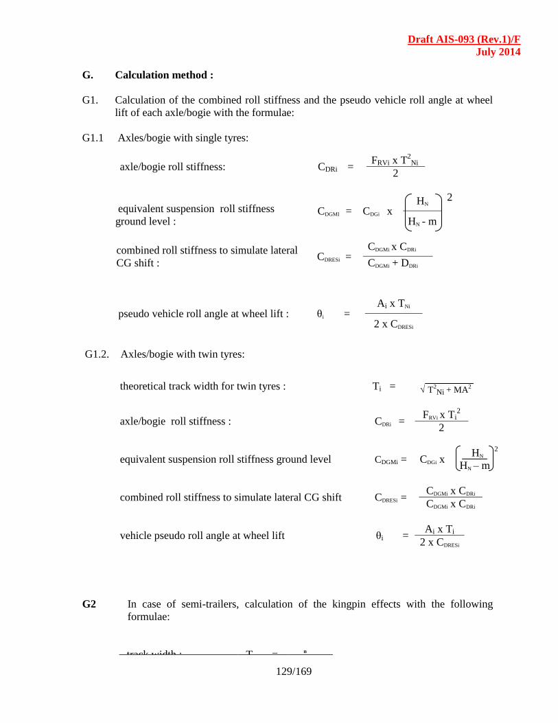
Draft AIS-093 (Rev.1)/F
July 2014
129/169
G. Calculation method :
G1. Calculation of the combined roll stiffness and the pseudo vehicle roll angle at wheel
lift of each axle/bogie with the formulae:
G1.1 Axles/bogie with single tyres:
G1.2. Axles/bogie with twin tyres:
theoretical track width for twin tyres : Ti =
√ T2Ni + MA
2
axle/bogie roll stiffness : CDRi = FRVi x Ti
2
2
equivalent suspension roll stiffness ground level CDGMi = CDGi x
HN
2
HN – m
combined roll stiffness to simulate lateral CG shift CDRESi = CDGMi x CDRi
CDGMi x CDRi
vehicle pseudo roll angle at wheel lift θi = Ai x Ti
2 x CDRESi
G2 In case of semi-trailers, calculation of the kingpin effects with the following
formulae:
track width : Tk = n
axle/bogie roll stiffness: CDRi = FRVi x T
2Ni
2
equivalent suspension roll stiffness
ground level : CDGMI = CDGi x
HN 2
HN - m
combined roll stiffness to simulate lateral
CG shift : CDRESi =
CDGMi x CDRi
CDGMi + DDRi
pseudo vehicle roll angle at wheel lift : θi = Ai x TNi
2 x CDRESi
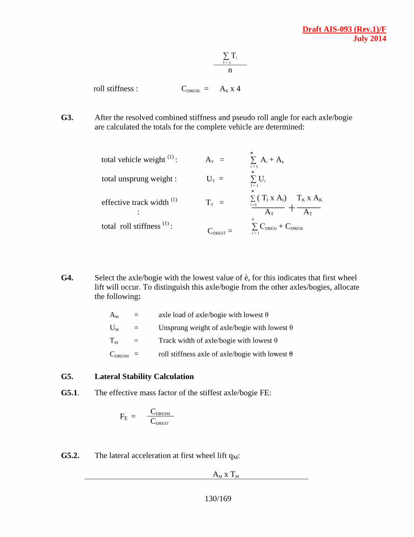
Draft AIS-093 (Rev.1)/F
July 2014
130/169
∑ Ti I = 1
n
roll stiffness : CDRESK = AK x 4
G3. After the resolved combined stiffness and pseudo roll angle for each axle/bogie
are calculated the totals for the complete vehicle are determined:
total vehicle weight (1)
: AT = n
∑ Ai + Ak i = 1
total unsprung weight : UT = n
∑ Ui I = 1
effective track width (1)
:
TT =
n
∑ ( Ti x Ai) TK x AK i =1
AT AT
total roll stiffness (1)
:
CDREST =
n
∑ CDRESi + CDRESk i = 1
G4. Select the axle/bogie with the lowest value of è, for this indicates that first wheel
lift will occur. To distinguish this axle/bogie from the other axles/bogies, allocate
the following:
AM = axle load of axle/bogie with lowest θ
UM = Unsprung weight of axle/bogie with lowest θ
TM = Track width of axle/bogie with lowest θ
CDRESM = roll stiffness axle of axle/bogie with lowest θ
G5. Lateral Stability Calculation
G5.1. The effective mass factor of the stiffest axle/bogie FE:
FE = CDRESM
CDREST
G5.2. The lateral acceleration at first wheel lift qM:
AM x TM

Draft AIS-093 (Rev.1)/F
July 2014
131/169
qM =
2x (FE x AT x HG) +
((AT-UT) x FE x HN )2
CDRESM - (AT x FE x HN )
G5.3. The maximum optimal theoretical lateral acceleration at overturn qT:
G5.4. Linear interpolation between the lateral acceleration at first wheel lift and the
Maximum theoretical lateral acceleration gives the correlated lateral
acceleration at overturn qc:
qC = qT - ( qT - qM ) x AM AT
qT =
AT x TT
2 x (AT x HG) +
((AT- UT) x HN)2
CDREST – ( AT x HN )
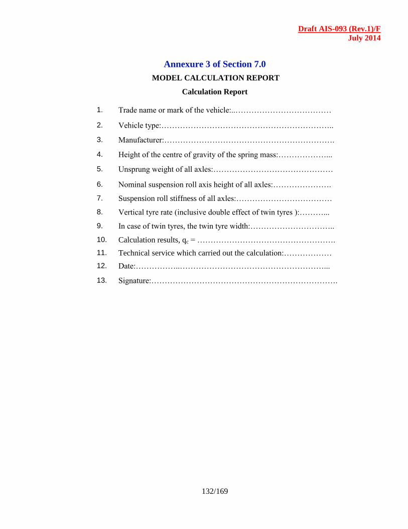
Draft AIS-093 (Rev.1)/F
July 2014
132/169
Annexure 3 of Section 7.0
MODEL CALCULATION REPORT
Calculation Report
1. Trade name or mark of the vehicle:..………………………………
2. Vehicle type:………………………………………………………..
3. Manufacturer:……………………………………………………….
4. Height of the centre of gravity of the spring mass:………………...
5. Unsprung weight of all axles:………………………………………
6. Nominal suspension roll axis height of all axles:………………….
7. Suspension roll stiffness of all axles:………………………………
8. Vertical tyre rate (inclusive double effect of twin tyres ):………...
9. In case of twin tyres, the twin tyre width:…………………………..
10. Calculation results, qc = …………………………………………….
11. Technical service which carried out the calculation:………………
12. Date:……………..………………………………………………...
13. Signature:…………………………………………………………….
Draft AIS-093 (Rev.1)/F
July 2014
133/169
SECTION - 8.0
TYPE APPROVAL AND COP PROCEDURE
8.1 SCOPE :
8.1.1 The Type Approval Procedure specified in this code is applicable to truck Cab
body including dangerous goods carriers with GVW greater than 3.5 tonnes
and trailers / semi-trailers.
8.1.2 The requirements of this code also apply to vehicles of N2, N3, T3 and T4
categories.
The requirements of this section as well as the Code would only apply to
organizations who construct cabs / bodies on chassis supplied by vehicle
manufacturers. It will not apply to the vehicle / chassis manufacturers who are
currently under the type approval and CMVR certification system within the
scope of this procedure.
8.1.3 The system for approval of Prototype (Rule 126) and Conformity to
Production (Rule 126A) to comply with provisions with respect to the safety,
strength and technical requirements specified in this “ Code of Practice for
Construction and approval for Truck Cab and Truck Bodies. Truck
Body and Trailers” and Trailer manufacturing (TM)” shall be based on
the standards notified from time to time.
8.2 Procedure for Type Approval :
8.2.1 Design of Truck Cab and Body Building / Trailer Manufacturing and
other Aggregates / Units :
8.2.1.1 Truck Cab and Body Builders (TCBB) / Trailer Manufacturers (TM) may
follow their own design complying with the provisions of this Code. They
shall follow the designs / recommendations of the vehicle / chassis
manufacturers, wherever necessary and applicable.
8.2.2 Prototype Type Approval of Vehicle / Trailer and other Aggregates /
Units :
8.2.2.1 TCBB shall submit application for Type Approval of prototype built as per
9.2.1.1 8.2.1.1 above.
Draft AIS-093 (Rev.1)/F
July 2014
134/169
8.3 Application for Type Approval :
8.3.1 The application for type approval of the vehicle type shall be submitted to the
Test Agency by the TCBB / TM with a description of the Vehicle
type(s)accompanied by the following documents, as applicable to the
provisions for which such compliance is sought:
a) List of provisions for which compliance is sought to be established.
b) The Truck body builder shall submit all the relevant information as given
in Annexure - I.
c) The Truck Body Builder shall submit additional information on Trucks
meant for carrying dangerous and hazardous goods as given in
Annexure – II.
d) The Trailer manufacturer shall submit the technical information as given
in Annexure – III.
c) Copies of certificates or test reports of compliance to various provisions,
which may have already been obtained from other recognized Testing
Agencies.
d) Copies of test reports for other models/variants, if any, which can be used
for establishing compliance of the model to be type approved, with a
note explaining the details.
e) Copy of certificate of incorporation of the organisation, if not already
submitted.
f) Publications available.
8.4 Type Approval of Safety Components / Sub-assemblies :
8.4.1 In addition to the safety components notified under Rule 124 of Central Motor
Vehicle Rules, 1989 the Type Approval of passenger seats and seat
mountings, window sub-assembly, power operated service door, door
components like locks and hinges, luggage rack assembly, wheel rims (in the
case of Trailers) etc., and any other components notified from time to time
shall be obtained separately and copies of such certificates / reports shall be
furnished in addition to the requirements stipulated in 9.3.1 8.3.1 above.
8.5 Methods of Establishing Compliance :
8.5.1 Depending upon the provision, the compliance can be established by either
comparison of the values declared in the Technical Specifications with those
in the provisions of Central Motor Vehicle Rules, 1989, or checking the
fitment of part(s) on the vehicle or by testing, as applicable. Applicability of
rules, method of establishing the compliance and details of the test procedures
shall be as specified in this code.

Draft AIS-093 (Rev.1)/F
July 2014
135/169
8.6 Certificate of Compliance for Type Approval :
8.6.1 After compliance is established for all the provisions, applicable to that
model/variant(s), a Certificate of Compliance consolidating all applicable
provisions shall be issued by the Testing Agency. The Technical
Specifications as declared by the manufacturer shall be counter signed by the
Testing Agency and shall be attached to the certificate of compliance.
8.7 Conformity of Production (CoP) :
8.7.1 CoP shall be carried out at least once in 12 months by any of the testing
agencies notified under Rule 126 of Central Motor Vehicle Rules, 1989, or
any other agency authorized by the Government. A minimum of one unit
shall be subjected to COP.
8.8 Non-Conformity of Production :
8.8.1 The accreditation granted to the truck cab and body building unit / trailer
manufacturing unit may be suspended or withdrawn in case of non
conformity. The unit may be re-evaluated as per directives of the Government.
Draft AIS-093 (Rev.1)/F
July 2014
136/169
SECTION - 9.0
ACCREDITATION SYSTEM FOR TRUCK CAB AND
BODY BUILDERS (TCBB) / TRAILER MANUFACTURERS (TM)
Truck Cab and Body Building as well as trailer / semi-trailer manufacturing is being
carried out by a large number of small and medium scale organizations spread throughout the
country. Truck Cab and Body Builder (TCBB) organizations construct the bodies on chassis
procured from vehicle / chassis manufacturers. Presently, only the vehicle / chassis
manufactured by vehicle manufacturers undergo a formal type approval and certification
procedure as per the various provisions of CMVR.
The Committee feels that there is a need to set up a formal institutional mechanism to
monitor the manufacturing and process conformity and compliance of CMVR provisions of
the above said TCBB / TM units. For example, in respect of items like petroleum tankers
and certain other hazardous goods carriers, there is an established control procedure
administered by the Chief Controller of Explosives. The Committee recommends that a
procedure on the above lines is instituted in respect of truck and body building as well as
trailer manufacturing.
The Committee also recommends creation of a cadre of technical personnel to effectively
implement the procedure in order to ensure that all truck cabs / bodies as well as trailers
comply with all the relevant provisions of the CMVR as well as the Code of Practice for
Truck Body / Trailer formulated in this document.
The Ministry of Shipping, Road Transport and Highways ( MoSRT&H ) , is presently
evolving a system for the Accreditation of the Bus Body Builders in the country. The
Committee also recommends that the same system be extended for the truck body building
and trailer manufacturing activity as well. MoSRT&H may separately notify the
administrative mechanism for the Accreditation of Truck Body Builders and Trailer
Manufacturers.

Draft AIS-093 (Rev.1)/F
July 2014
137/169
Annexure – I
(See 8.3.1(b))
(To be submitted by the Vehicle Manufacturer / Body Builder to the Test Agency)
TECHNICAL INFORMATION ON TRUCK CAB, LOAD BODY &
RELATED TECHNICAL FEATURES
1.0 Details of Vehicle Manufacturer
1.1 Name & address of the vehicle manufacturer
1.2 Telephone No.
1.3 Fax. No.
1.4 E-mail address
1.5 Contact person
1.6 Plant(s)of manufacture
2.0 Details of Truck Body / Tanker Builder
2.1 Name & address of the body builder
2.2 Telephone No.
2.3 Fax. No.
2.4 E-mail address
2.5 Contact person
3.0 Name of model and variants (if any)
3.1 CMVR certificate reference(s)
3.2 Type and General commercial description (s)
4.0 Vehicle type
4.1 Type of vehicle (rigid / articulated / combination)
4.2 Usage (goods / passenger / tractor / trailer / others)
4.3 Control (forward / semi-forward / normal / others)
4.4 Drive (4x2 / 4x4 / 6x4 / others)
4.5 Cab type (fully built cab/sleeper cab/cowl/front end structure/with wind
shield/without wind shield)
4.6 Load body, type and drawing
5.0 Category of vehicle
5.1 As per AIS 053 as amended from time to time IS:14272 (Part 1)
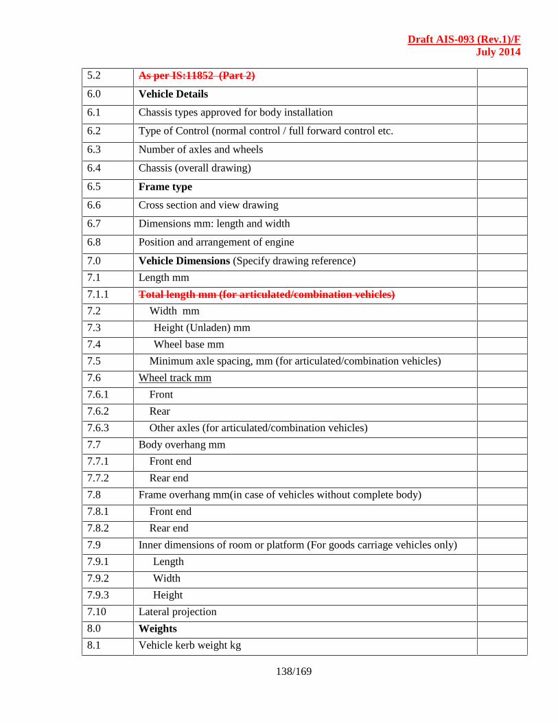
Draft AIS-093 (Rev.1)/F
July 2014
138/169
5.2 As per IS:11852 (Part 2)
6.0 Vehicle Details
6.1 Chassis types approved for body installation
6.2 Type of Control (normal control / full forward control etc.
6.3 Number of axles and wheels
6.4 Chassis (overall drawing)
6.5 Frame type
6.6 Cross section and view drawing
6.7 Dimensions mm: length and width
6.8 Position and arrangement of engine
7.0 Vehicle Dimensions (Specify drawing reference)
7.1 Length mm
7.1.1 Total length mm (for articulated/combination vehicles)
7.2 Width mm
7.3 Height (Unladen) mm
7.4 Wheel base mm
7.5 Minimum axle spacing, mm (for articulated/combination vehicles)
7.6 Wheel track mm
7.6.1 Front
7.6.2 Rear
7.6.3 Other axles (for articulated/combination vehicles)
7.7 Body overhang mm
7.7.1 Front end
7.7.2 Rear end
7.8 Frame overhang mm(in case of vehicles without complete body)
7.8.1 Front end
7.8.2 Rear end
7.9 Inner dimensions of room or platform (For goods carriage vehicles only)
7.9.1 Length
7.9.2 Width
7.9.3 Height
7.10 Lateral projection
8.0 Weights
8.1 Vehicle kerb weight kg
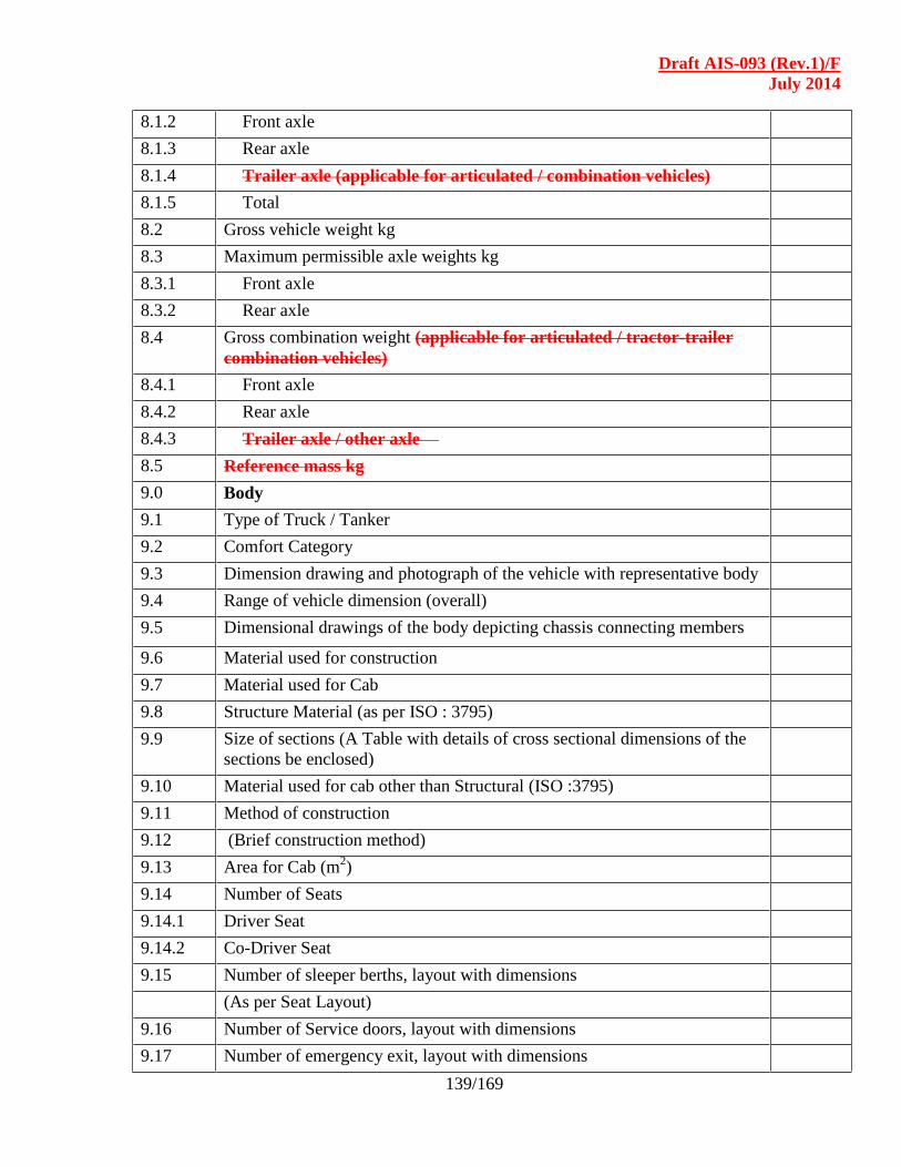
Draft AIS-093 (Rev.1)/F
July 2014
139/169
8.1.2 Front axle
8.1.3 Rear axle
8.1.4 Trailer axle (applicable for articulated / combination vehicles)
8.1.5 Total
8.2 Gross vehicle weight kg
8.3 Maximum permissible axle weights kg
8.3.1 Front axle
8.3.2 Rear axle
8.4 Gross combination weight (applicable for articulated / tractor-trailer
combination vehicles)
8.4.1 Front axle
8.4.2 Rear axle
8.4.3 Trailer axle / other axle
8.5 Reference mass kg
9.0 Body
9.1 Type of Truck / Tanker
9.2 Comfort Category
9.3 Dimension drawing and photograph of the vehicle with representative body
9.4 Range of vehicle dimension (overall)
9.5 Dimensional drawings of the body depicting chassis connecting members
9.6 Material used for construction
9.7 Material used for Cab
9.8 Structure Material (as per ISO : 3795)
9.9 Size of sections (A Table with details of cross sectional dimensions of the
sections be enclosed)
9.10 Material used for cab other than Structural (ISO :3795)
9.11 Method of construction
9.12 (Brief construction method)
9.13 Area for Cab (m2)
9.14 Number of Seats
9.14.1 Driver Seat
9.14.2 Co-Driver Seat
9.15 Number of sleeper berths, layout with dimensions
(As per Seat Layout)
9.16 Number of Service doors, layout with dimensions
9.17 Number of emergency exit, layout with dimensions

Draft AIS-093 (Rev.1)/F
July 2014
140/169
9.18 Number of escape hatches, layout with dimensions
9.19 Area of luggage Transportation on roof (m2), layout with dimensions
10.0 Clearance
10.1 Minimum road ground clearance
10.2 Road clearance from floor
10.3 Approach angle
10.4 Departure angle
10.5 Ramp-over angle
11.0 Seating capacity
11.1 Maximum (including driver) for completely built vehicles
11.2 Sketch showing layout of seats with appropriate dimensions of seats & their
location on the vehicle platform
12.0 Maximum Stable inclination
12.1 Left
12.2 Right
13.0 Body Panels
13.1 Outer Panels
13.1.1 Material
13.1.2 Thickness
13.2 Inner Panels
13.2.1 Material
13.2.2 Thickness
13.3 Roof Panels (If closed type load carrier)
13.3.1 Material
13.3.2 Thickness
13.4 Floor Panels
13.4.1 Material
13.4.2 Thickness
13.5 Type of anti-slip coating
14.0 Step well Guard
14.1 Height from the floor
14.2 Projection from the side wall
15.0 Cab Luggage Rack
15.1 Width from sidewall
15.2 Height from Roof
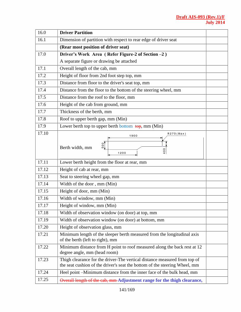
Draft AIS-093 (Rev.1)/F
July 2014
141/169
16.0 Driver Partition
16.1 Dimension of partition with respect to rear edge of driver seat
(Rear most position of driver seat)
17.0 Driver’s Work Area ( Refer Figure-2 of Section –2 )
A separate figure or drawing be attached
17.1 Overall length of the cab, mm
17.2 Height of floor from 2nd foot step top, mm
17.3 Distance from floor to the driver's seat top, mm
17.4 Distance from the floor to the bottom of the steering wheel, mm
17.5 Distance from the roof to the floor, mm
17.6 Height of the cab from ground, mm
17.7 Thickness of the berth, mm
17.8 Roof to upper berth gap, mm (Min)
17.9 Lower berth top to upper berth bottom top, mm (Min)
17.10
Berth width, mm
17.11 Lower berth height from the floor at rear, mm
17.12 Height of cab at rear, mm
17.13 Seat to steering wheel gap, mm
17.14 Width of the door , mm (Min)
17.15 Height of door, mm (Min)
17.16 Width of window, mm (Min)
17.17 Height of window, mm (Min)
17.18 Width of observation window (on door) at top, mm
17.19 Width of observation window (on door) at bottom, mm
17.20 Height of observation glass, mm
17.21 Minimum length of the sleeper berth measured from the longitudinal axis
of the berth (left to right), mm
17.22 Minimum distance from H point to roof measured along the back rest at 12
degree angle, mm (head room)
17.23 Thigh clearance for the driver-The vertical distance measured from top of
the seat cushion of the driver's seat the bottom of the steering Wheel, mm
17.24 Heel point –Minimum distance from the inner face of the bulk head, mm
17.25 Overall length of the cab, mm Adjustment range for the thigh clearance,
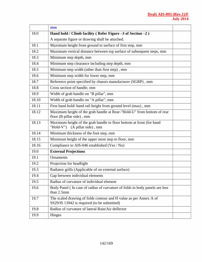
Draft AIS-093 (Rev.1)/F
July 2014
142/169
mm
18.0 Hand hold / Climb facility ( Refer Figure –3 of Section –2 )
A separate figure or drawing shall be attached.
18.1 Maximum height from ground to surface of first step, mm
18.2 Maximum vertical distance between top surface of subsequent steps, mm
18.3 Minimum step depth, mm
18.4 Minimum step clearance including step depth, mm
18.5 Minimum step width (other than first step) , mm
18.6 Minimum step width for lower step, mm
18.7 Reference point specified by chassis manufacturer (SGRP) , mm
18.8 Cross section of handle, mm
18.9 Width of grab handle on "B pillar", mm
18.10 Width of grab handle on "A pillar", mm
18.11 First hand hold/ hand rail height from ground level (max) , mm
18.12 Maximum height of the grab handle at Rear-"Hold-U" from bottom of rear
floor (B pillar side) , mm
18.13 Maximum height of the grab handle to floor bottom at front (for hand
"Hold-V") (A pillar side) , mm
18.14 Minimum thickness of the foot step, mm
18.15 Minimum height of the upper most step to floor, mm
18.16 Compliance to AIS-046 established (Yes / No)
19.0 External Projections
19.1 Ornaments
19.2 Projection for headlight
19.3 Radiator grills (Applicable of on external surface)
19.4 Gap between individual elements
19.5 Radius of curvature of individual element
19.6 Body Panel ( In case of radius of curvature of folds in body panels are less
than 2.5mm
19.7 The scaled drawing of folds contour and H value as per Annex A of
SS29/IS 13942 is required (to be submitted)
19.8 Radius of curvature of lateral Rain/Air deflector
19.9 Hinges

Draft AIS-093 (Rev.1)/F
July 2014
143/169
19.10 Handles
20.0 Rear Under run Protective device ( RUPD )
20.1 Height of lower edge of the device from the ground (mm)
20.2 Width of the device (mm)
20.3 Drawing of the rear under-run protective device with dimensions.
20.4 Material (Metal/Fibre/etc.)
21.0 Lateral Protection (Side Guards)
21.1 Height of the lower edge of the Side Guard.
21.2 Drawing of the lateral protection device fitted on the vehicle with
dimensions
21.3 Material (Metal/Fiber/etc.)
22.0 Driver / Co-driver door
22.1 Make & identification
22.2 Name of the producer
22.3 Position of controls
22.4 Control Circuit (schematic diagram)
23.0 Door locks and hinges
23.1 Doors
23.1.1 No. of doors
23.1.2 Position and type of door
23.2 Door lock
23.2.1 Name of manufacturer
23.2.2 Identification mark
23.3 Door hinge
23.3.1 Name of manufacturer
23.3.2 Identification mark
24.0 Hood latch
24.1 Name of manufacturer
24.2 Type
24.3 Identification mark
25.0 Windows on driver / co-driver door
25.1 Winding type provided (Yes/No)
26.0 Windows other than door windows
26.1 Type and description
26.2 Drawing with dimensions

Draft AIS-093 (Rev.1)/F
July 2014
144/169
27.0 Safety glass
27.1 Front windshield (laminated)
27.1.1 Make and identification
27.1.2 Type (flat/curved, clear/tinted)
27.1.3 Thickness mm
27.1.4 No. of pieces
27.1.5 Radius of curvature (If curved)
27.2 Side Windows
27.2.1 Make and identification
27.2.2 Type (flat/curved, clear/tinted, toughened)
27.2.3 Thickness mm
27.2.4 Radius of curvature (If curved)
27.3 Rear Window
27.3.1 Make and identification
27.3.2 Type (flat/curved, clear/tinted, toughened)
27.3.3 Thickness mm
27.3.4 Radius of curvature (If curved)
28.0 Rear view mirror
28.1 Left
28.1.1 Name of producer
28.1.2 Type
28.1.3 Class of mirror
28.1.4 Manufacturer’s ID number
28.1.5 Trade name or mark location
28.1.6 Dimension & radius of curvature
28.2 Right
28.2.1 Name of producer
28.2.2 Type
28.2.3 Class of mirror
28.2.4 Manufacturer’s ID number
28.2.5 Trade name or mark location
28.2.6 Dimension & radius of curvature
28.3 Inside
28.3.1 Name of producer
28.3.2 Type
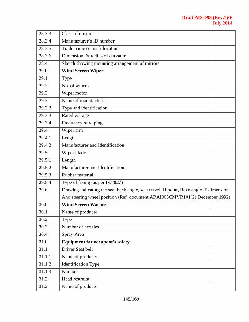
Draft AIS-093 (Rev.1)/F
July 2014
145/169
28.3.3 Class of mirror
28.3.4 Manufacturer’s ID number
28.3.5 Trade name or mark location
28.3.6 Dimension & radius of curvature
28.4 Sketch showing mounting arrangement of mirrors
29.0 Wind Screen Wiper
29.1 Type
29.2 No. of wipers
29.3 Wiper motor
29.3.1 Name of manufacturer
29.3.2 Type and identification
29.3.3 Rated voltage
29.3.4 Frequency of wiping
29.4 Wiper arm
29.4.1 Length
29.4.2 Manufacturer and Identification
29.5 Wiper blade
29.5.1 Length
29.5.2 Manufacturer and Identification
29.5.3 Rubber material
29.5.4 Type of fixing (as per IS:7827)
29.6 Drawing indicating the seat back angle, seat travel, H point, Rake angle ,F dimension
And steering wheel position (Ref document ARAI005CMVR101(2) December 1992)
30.0 Wind Screen Washer
30.1 Name of producer
30.2 Type
30.3 Number of nozzles
30.4 Spray Area
31.0 Equipment for occupant's safety
31.1 Driver Seat belt
31.1.1 Name of producer
31.1.2 Identification Type
31.1.3 Number
31.2 Head restraint
31.2.1 Name of producer

Draft AIS-093 (Rev.1)/F
July 2014
146/169
31.2.2 Type
31.3 Passenger Seat
31.3.1 Name of producer
31.3.2 Type
31.3.3 Frame structure Material
31.3.4 Section size
31.3.5 Pad material
31.3.6 Upholstery
32.0 Super Structure (Load body)
32.1 Type and description
32.2 Floor Height from the ground (unladen)
32.3 Slope of floor
32.4 Material used for Floor construction
32.5 No. of Cross sections used
32.6 (If more than two tabulate in a table)
32.7 Details of the Load Body Carrier
32.8 Maximum Height
32.9 Maximum Width
32.10 Maximum Length
33.0 Bumper
33.1 Size
33.1.1 Front
33.1.2 Rear
33.2 External Projection
33.3 Clearance between bumper & body
34.0 Spray Suppression System
34.1 Make, Country of origin (If imported)
34.2 Type ( Water seperator / Pulveriser )
34.3 Identification No. / Part No.
34.4 Size
34.5 Drawing / Photographs showing the mounting details with dimensions
35.0 Fuel filler
35.1 Aperture
35.2 Position
36.0 Fire Extinguisher
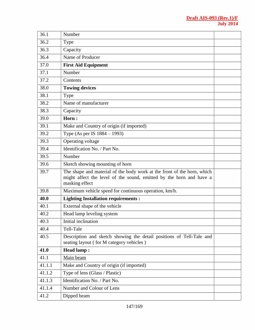
Draft AIS-093 (Rev.1)/F
July 2014
147/169
36.1 Number
36.2 Type
36.3 Capacity
36.4 Name of Producer
37.0 First Aid Equipment
37.1 Number
37.2 Contents
38.0 Towing devices
38.1 Type
38.2 Name of manufacturer
38.3 Capacity
39.0 Horn :
39.1 Make and Country of origin (if imported)
39.2 Type (As per IS 1884 – 1993)
39.3 Operating voltage
39.4 Identification No. / Part No.
39.5 Number
39.6 Sketch showing mounting of horn
39.7 The shape and material of the body work at the front of the horn, which
might affect the level of the sound, emitted by the horn and have a
masking effect
39.8 Maximum vehicle speed for continuous operation, km/h.
40.0 Lighting Installation requirements :
40.1 External shape of the vehicle
40.2 Head lamp leveling system
40.3 Initial inclination
40.4 Tell-Tale
40.5 Description and sketch showing the detail positions of Tell-Tale and
seating layout ( for M category vehicles )
41.0 Head lamp :
41.1 Main beam
41.1.1 Make and Country of origin (if imported)
41.1.2 Type of lens (Glass / Plastic)
41.1.3 Identification No. / Part No.
41.1.4 Number and Colour of Lens
41.2 Dipped beam
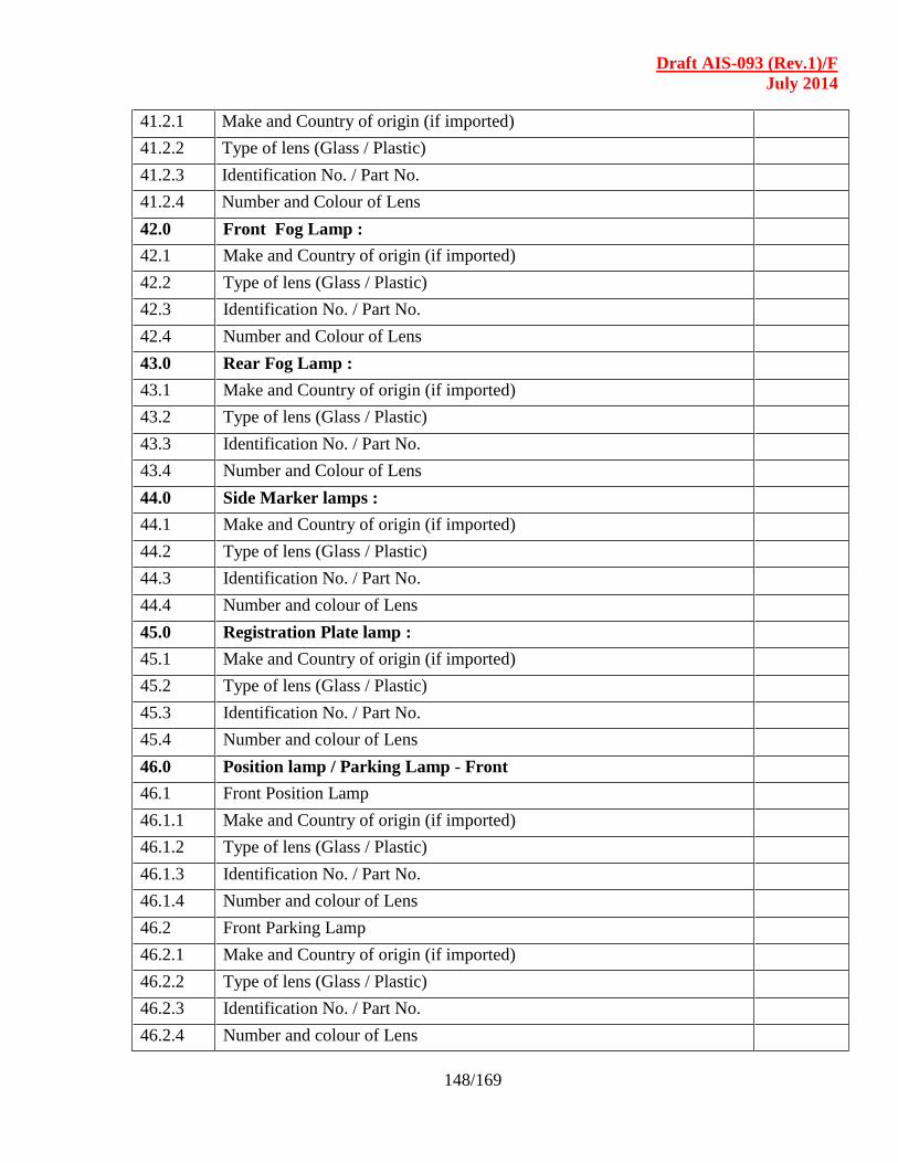
Draft AIS-093 (Rev.1)/F
July 2014
148/169
41.2.1 Make and Country of origin (if imported)
41.2.2 Type of lens (Glass / Plastic)
41.2.3 Identification No. / Part No.
41.2.4 Number and Colour of Lens
42.0 Front Fog Lamp :
42.1 Make and Country of origin (if imported)
42.2 Type of lens (Glass / Plastic)
42.3 Identification No. / Part No.
42.4 Number and Colour of Lens
43.0 Rear Fog Lamp :
43.1 Make and Country of origin (if imported)
43.2 Type of lens (Glass / Plastic)
43.3 Identification No. / Part No.
43.4 Number and Colour of Lens
44.0 Side Marker lamps :
44.1 Make and Country of origin (if imported)
44.2 Type of lens (Glass / Plastic)
44.3 Identification No. / Part No.
44.4 Number and colour of Lens
45.0 Registration Plate lamp :
45.1 Make and Country of origin (if imported)
45.2 Type of lens (Glass / Plastic)
45.3 Identification No. / Part No.
45.4 Number and colour of Lens
46.0 Position lamp / Parking Lamp - Front
46.1 Front Position Lamp
46.1.1 Make and Country of origin (if imported)
46.1.2 Type of lens (Glass / Plastic)
46.1.3 Identification No. / Part No.
46.1.4 Number and colour of Lens
46.2 Front Parking Lamp
46.2.1 Make and Country of origin (if imported)
46.2.2 Type of lens (Glass / Plastic)
46.2.3 Identification No. / Part No.
46.2.4 Number and colour of Lens
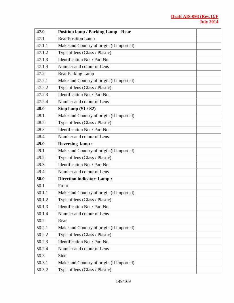
Draft AIS-093 (Rev.1)/F
July 2014
149/169
47.0 Position lamp / Parking Lamp - Rear
47.1 Rear Position Lamp
47.1.1 Make and Country of origin (if imported)
47.1.2 Type of lens (Glass / Plastic)
47.1.3 Identification No. / Part No.
47.1.4 Number and colour of Lens
47.2 Rear Parking Lamp
47.2.1 Make and Country of origin (if imported)
47.2.2 Type of lens (Glass / Plastic)
47.2.3 Identification No. / Part No.
47.2.4 Number and colour of Lens
48.0 Stop lamp (S1 / S2)
48.1 Make and Country of origin (if imported)
48.2 Type of lens (Glass / Plastic)
48.3 Identification No. / Part No.
48.4 Number and colour of Lens
49.0 Reversing lamp :
49.1 Make and Country of origin (if imported)
49.2 Type of lens (Glass / Plastic)
49.3 Identification No. / Part No.
49.4 Number and colour of Lens
50.0 Direction indicator Lamp :
50.1 Front
50.1.1 Make and Country of origin (if imported)
50.1.2 Type of lens (Glass / Plastic)
50.1.3 Identification No. / Part No.
50.1.4 Number and colour of Lens
50.2 Rear
50.2.1 Make and Country of origin (if imported)
50.2.2 Type of lens (Glass / Plastic)
50.2.3 Identification No. / Part No.
50.2.4 Number and colour of Lens
50.3 Side
50.3.1 Make and Country of origin (if imported)
50.3.2 Type of lens (Glass / Plastic)
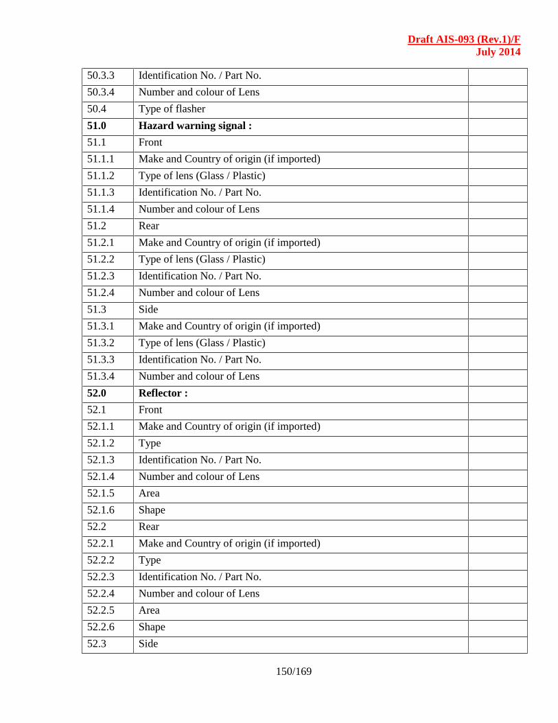
Draft AIS-093 (Rev.1)/F
July 2014
150/169
50.3.3 Identification No. / Part No.
50.3.4 Number and colour of Lens
50.4 Type of flasher
51.0 Hazard warning signal :
51.1 Front
51.1.1 Make and Country of origin (if imported)
51.1.2 Type of lens (Glass / Plastic)
51.1.3 Identification No. / Part No.
51.1.4 Number and colour of Lens
51.2 Rear
51.2.1 Make and Country of origin (if imported)
51.2.2 Type of lens (Glass / Plastic)
51.2.3 Identification No. / Part No.
51.2.4 Number and colour of Lens
51.3 Side
51.3.1 Make and Country of origin (if imported)
51.3.2 Type of lens (Glass / Plastic)
51.3.3 Identification No. / Part No.
51.3.4 Number and colour of Lens
52.0 Reflector :
52.1 Front
52.1.1 Make and Country of origin (if imported)
52.1.2 Type
52.1.3 Identification No. / Part No.
52.1.4 Number and colour of Lens
52.1.5 Area
52.1.6 Shape
52.2 Rear
52.2.1 Make and Country of origin (if imported)
52.2.2 Type
52.2.3 Identification No. / Part No.
52.2.4 Number and colour of Lens
52.2.5 Area
52.2.6 Shape
52.3 Side
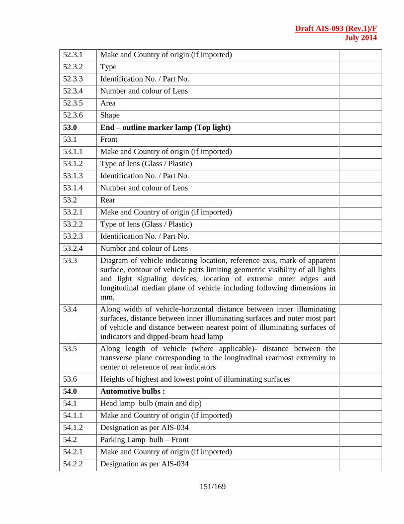
Draft AIS-093 (Rev.1)/F
July 2014
151/169
52.3.1 Make and Country of origin (if imported)
52.3.2 Type
52.3.3 Identification No. / Part No.
52.3.4 Number and colour of Lens
52.3.5 Area
52.3.6 Shape
53.0 End – outline marker lamp (Top light)
53.1 Front
53.1.1 Make and Country of origin (if imported)
53.1.2 Type of lens (Glass / Plastic)
53.1.3 Identification No. / Part No.
53.1.4 Number and colour of Lens
53.2 Rear
53.2.1 Make and Country of origin (if imported)
53.2.2 Type of lens (Glass / Plastic)
53.2.3 Identification No. / Part No.
53.2.4 Number and colour of Lens
53.3 Diagram of vehicle indicating location, reference axis, mark of apparent
surface, contour of vehicle parts limiting geometric visibility of all lights
and light signaling devices, location of extreme outer edges and
longitudinal median plane of vehicle including following dimensions in
mm.
53.4 Along width of vehicle-horizontal distance between inner illuminating
surfaces, distance between inner illuminating surfaces and outer most part
of vehicle and distance between nearest point of illuminating surfaces of
indicators and dipped-beam head lamp
53.5 Along length of vehicle (where applicable)- distance between the
transverse plane corresponding to the longitudinal rearmost extremity to
center of reference of rear indicators
53.6 Heights of highest and lowest point of illuminating surfaces
54.0 Automotive bulbs :
54.1 Head lamp bulb (main and dip)
54.1.1 Make and Country of origin (if imported)
54.1.2 Designation as per AIS-034
54.2 Parking Lamp bulb – Front
54.2.1 Make and Country of origin (if imported)
54.2.2 Designation as per AIS-034
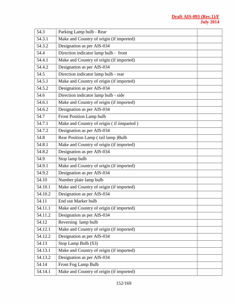
Draft AIS-093 (Rev.1)/F
July 2014
152/169
54.3 Parking Lamp bulb - Rear
54.3.1 Make and Country of origin (if imported)
54.3.2 Designation as per AIS-034
54.4 Direction indicator lamp bulb - front
54.4.1 Make and Country of origin (if imported)
54.4.2 Designation as per AIS-034
54.5 Direction indicator lamp bulb - rear
54.5.1 Make and Country of origin (if imported)
54.5.2 Designation as per AIS-034
54.6 Direction indicator lamp bulb - side
54.6.1 Make and Country of origin (if imported)
54.6.2 Designation as per AIS-034
54.7 Front Position Lamp bulb
54.7.1 Make and Country of origin ( if iimparted )
54.7.2 Designation as per AIS-034
54.8 Rear Position Lamp ( tail lamp )Bulb
54.8.1 Make and Country of origin (if imported)
54.8.2 Designation as per AIS-034
54.9 Stop lamp bulb
54.9.1 Make and Country of origin (if imported)
54.9.2 Designation as per AIS-034
54.10 Number plate lamp bulb
54.10.1 Make and Country of origin (if imported)
54.10.2 Designation as per AIS-034
54.11 End out Marker bulb
54.11.1 Make and Country of origin (if imported)
54.11.2 Designation as per AIS-034
54.12 Reversing lamp bulb
54.12.1 Make and Country of origin (if imported)
54.12.2 Designation as per AIS-034
54.13 Stop Lamp Bulb (S3)
54.13.1 Make and Country of origin (if imported)
54.13.2 Designation as per AIS-034
54.14 Front Fog Lamp Bulb
54.14.1 Make and Country of origin (if imported)

Draft AIS-093 (Rev.1)/F
July 2014
153/169
54.14.2 Designation as per AIS-034
54.15 Rear Fog Lamp Bulb
54.15.1 Make and Country of origin (if imported)
54.15.2 Designation as per AIS-034
54.16 Side Marker Lamp Bulb
54.16.1 Make and Country of origin (if imported)
54.16.2 Designation as per AIS-034
55.0 Internal Lighting & Illumination
55.1 Driver Cab lighting :
55.1.1 Type :
55.1.2 Name of producer :
55.1.3 Number :
55.1.4 Illumination intensity :
55.2 Passenger Compartment Lighting
55.2.1 Type :
55.2.2 Name of producer :
55.2.3 Number :
55.2.4 Illumination intensity :
56.0 Other Area Lighting
56.1 Type :
56.2 Name of producer :
56.3 Number :
56.4 Illumination intensity :
57.0 Electrical Circuit
57.1 Circuit Diagram (attach details):
58.0 Electrical Cables
58.1 Name of producer :
58.2 Conductor Cross section :
58.3 Insulation Class :
59.0 Fuse
59.1 Type & Make
59.2 Name of producer
60.0 Master switch for electrical
60.1 Type & Make
60.2 Name of producer
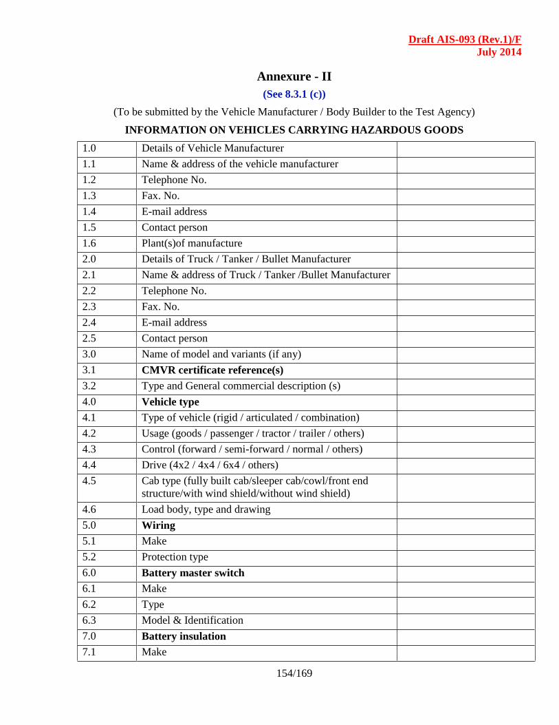
Draft AIS-093 (Rev.1)/F
July 2014
154/169
Annexure - II
(See 8.3.1 (c))
(To be submitted by the Vehicle Manufacturer / Body Builder to the Test Agency)
INFORMATION ON VEHICLES CARRYING HAZARDOUS GOODS
1.0 Details of Vehicle Manufacturer
1.1 Name & address of the vehicle manufacturer
1.2 Telephone No.
1.3 Fax. No.
1.4 E-mail address
1.5 Contact person
1.6 Plant(s)of manufacture
2.0 Details of Truck / Tanker / Bullet Manufacturer
2.1 Name & address of Truck / Tanker /Bullet Manufacturer
2.2 Telephone No.
2.3 Fax. No.
2.4 E-mail address
2.5 Contact person
3.0 Name of model and variants (if any)
3.1 CMVR certificate reference(s)
3.2 Type and General commercial description (s)
4.0 Vehicle type
4.1 Type of vehicle (rigid / articulated / combination)
4.2 Usage (goods / passenger / tractor / trailer / others)
4.3 Control (forward / semi-forward / normal / others)
4.4 Drive (4x2 / 4x4 / 6x4 / others)
4.5 Cab type (fully built cab/sleeper cab/cowl/front end
structure/with wind shield/without wind shield)
4.6 Load body, type and drawing
5.0 Wiring
5.1 Make
5.2 Protection type
6.0 Battery master switch
6.1 Make
6.2 Type
6.3 Model & Identification
7.0 Battery insulation
7.1 Make
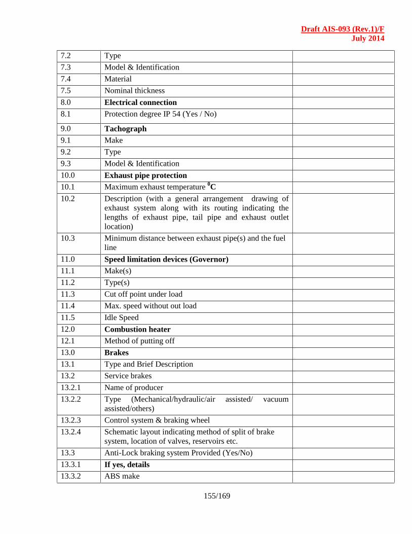
Draft AIS-093 (Rev.1)/F
July 2014
155/169
7.2 Type
7.3 Model & Identification
7.4 Material
7.5 Nominal thickness
8.0 Electrical connection
8.1 Protection degree IP 54 (Yes / No)
9.0 Tachograph
9.1 Make
9.2 Type
9.3 Model & Identification
10.0 Exhaust pipe protection
10.1 Maximum exhaust temperature 0C
10.2 Description (with a general arrangement drawing of
exhaust system along with its routing indicating the
lengths of exhaust pipe, tail pipe and exhaust outlet
location)
10.3 Minimum distance between exhaust pipe(s) and the fuel
line
11.0 Speed limitation devices (Governor)
11.1 Make(s)
11.2 Type(s)
11.3 Cut off point under load
11.4 Max. speed without out load
11.5 Idle Speed
12.0 Combustion heater
12.1 Method of putting off
13.0 Brakes
13.1 Type and Brief Description
13.2 Service brakes
13.2.1 Name of producer
13.2.2 Type (Mechanical/hydraulic/air assisted/ vacuum
assisted/others)
13.2.3 Control system & braking wheel
13.2.4 Schematic layout indicating method of split of brake
system, location of valves, reservoirs etc.
13.3 Anti-Lock braking system Provided (Yes/No)
13.3.1 If yes, details
13.3.2 ABS make

Draft AIS-093 (Rev.1)/F
July 2014
156/169
13.4 Electronic Control Unit (ECU)
13.4.1 Make
13.4.2 Identification mark
13.5 Wheel Speed Sensor
13.5.1 Make
13.5.2 Identification mark
13.5.3 No. of sensors used
13.6 Hydraulic Modulator
13.6.1 Make
13.6.2 Identification mark
13.7 Solenoid Valve
13.7.1 Make
13.7.2 Identification mark
13.7.3 Max. designed pressure, kg/cm2
13.7.4 Max. working pressure, kg/cm2
13.8 Safety lamp provided (Yes/No)
13.9 Schematic layout of the ABS system
13.10 If ASR is used, give details
13.11 Brake lining (or) Pad
13.11.1 Nominal Dimensions, (mm)
(Length x Width x thickness)
13.11.1.1 Front wheel
13.11.1.2 Rear wheel
13.11.1.3 Others (in case of Tandem axle, give axle wise data)
13.11.2 Effective area per axle (cm2)
13.11.2.1 Front axle
13.11.2.2 Rear axle
13.11.2.3 Others (in case of Tandem axle, give axle wise data)
13.11.3 Material
13.11.4 Make and Designation
13.11.4.1 Front wheel / axle
13.11.4.2 Rear wheel / axle
13.11.4.3 Others (In case of Tandem axle provide data for each
axle)
13.11.5 Whether asbestos or asbestos-free?
13.12 Brake drum or disc
13.12.1 Effective diameter, mm
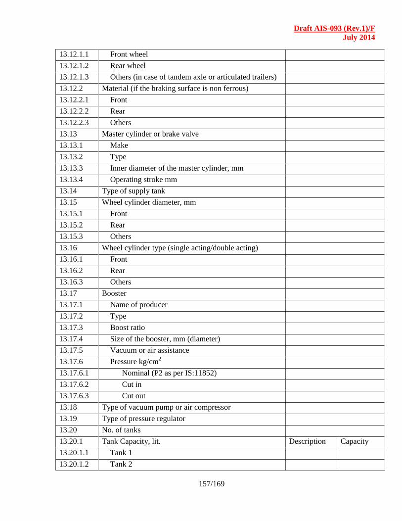
Draft AIS-093 (Rev.1)/F
July 2014
157/169
13.12.1.1 Front wheel
13.12.1.2 Rear wheel
13.12.1.3 Others (in case of tandem axle or articulated trailers)
13.12.2 Material (if the braking surface is non ferrous)
13.12.2.1 Front
13.12.2.2 Rear
13.12.2.3 Others
13.13 Master cylinder or brake valve
13.13.1 Make
13.13.2 Type
13.13.3 Inner diameter of the master cylinder, mm
13.13.4 Operating stroke mm
13.14 Type of supply tank
13.15 Wheel cylinder diameter, mm
13.15.1 Front
13.15.2 Rear
13.15.3 Others
13.16 Wheel cylinder type (single acting/double acting)
13.16.1 Front
13.16.2 Rear
13.16.3 Others
13.17 Booster
13.17.1 Name of producer
13.17.2 Type
13.17.3 Boost ratio
13.17.4 Size of the booster, mm (diameter)
13.17.5 Vacuum or air assistance
13.17.6 Pressure kg/cm2
13.17.6.1 Nominal (P2 as per IS:11852)
13.17.6.2 Cut in
13.17.6.3 Cut out
13.18 Type of vacuum pump or air compressor
13.19 Type of pressure regulator
13.20 No. of tanks
13.20.1 Tank Capacity, lit. Description Capacity
13.20.1.1 Tank 1
13.20.1.2 Tank 2
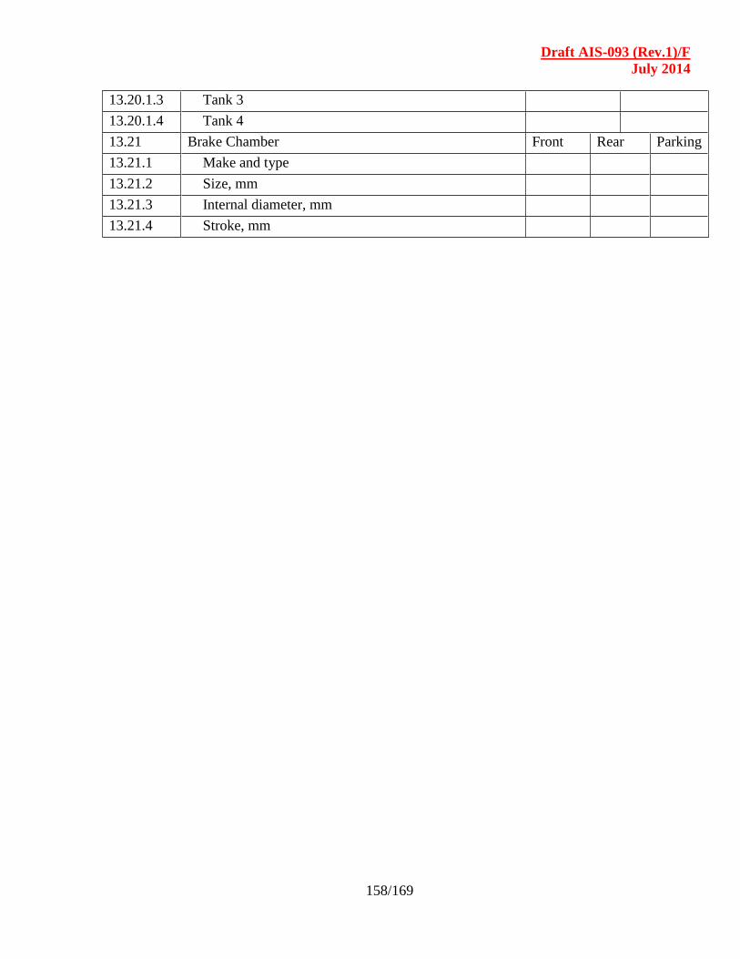
Draft AIS-093 (Rev.1)/F
July 2014
158/169
13.20.1.3 Tank 3
13.20.1.4 Tank 4
13.21 Brake Chamber Front Rear Parking
13.21.1 Make and type
13.21.2 Size, mm
13.21.3 Internal diameter, mm
13.21.4 Stroke, mm
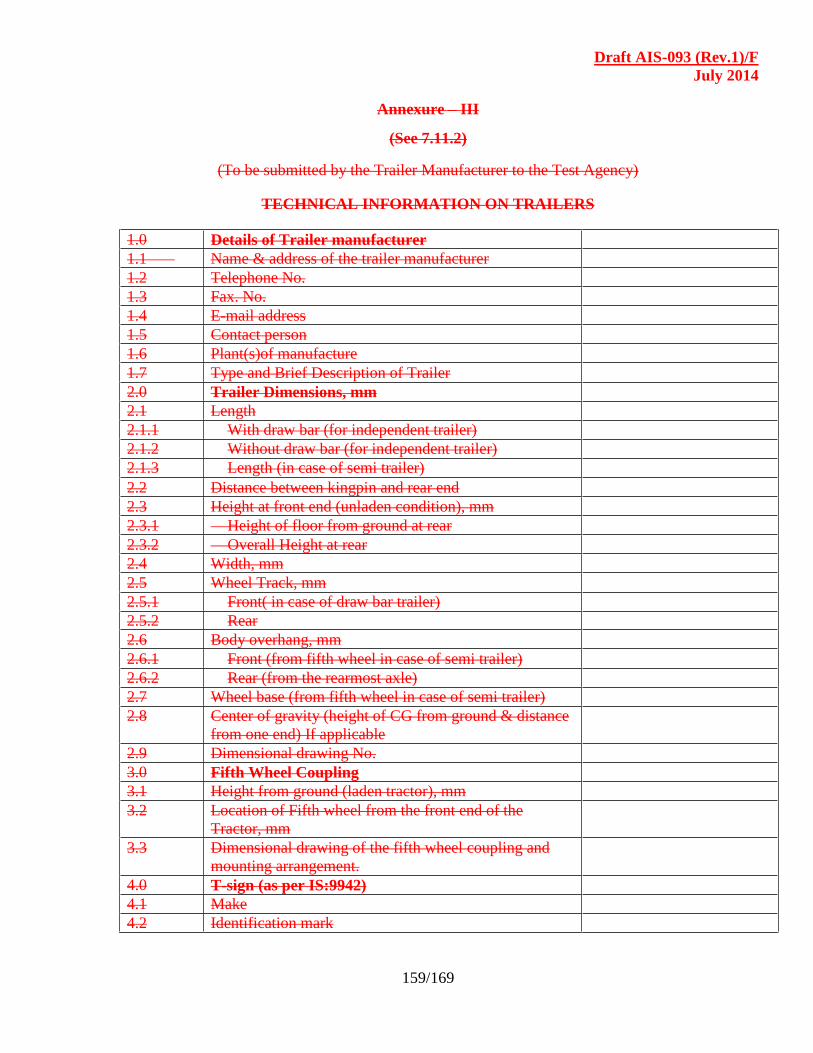
Draft AIS-093 (Rev.1)/F
July 2014
159/169
Annexure – III
(See 7.11.2)
(To be submitted by the Trailer Manufacturer to the Test Agency)
TECHNICAL INFORMATION ON TRAILERS
1.0 Details of Trailer manufacturer
1.1 Name & address of the trailer manufacturer
1.2 Telephone No.
1.3 Fax. No.
1.4 E-mail address
1.5 Contact person
1.6 Plant(s)of manufacture
1.7 Type and Brief Description of Trailer
2.0 Trailer Dimensions, mm
2.1 Length
2.1.1 With draw bar (for independent trailer)
2.1.2 Without draw bar (for independent trailer)
2.1.3 Length (in case of semi trailer)
2.2 Distance between kingpin and rear end
2.3 Height at front end (unladen condition), mm
2.3.1 Height of floor from ground at rear
2.3.2 Overall Height at rear
2.4 Width, mm
2.5 Wheel Track, mm
2.5.1 Front( in case of draw bar trailer)
2.5.2 Rear
2.6 Body overhang, mm
2.6.1 Front (from fifth wheel in case of semi trailer)
2.6.2 Rear (from the rearmost axle)
2.7 Wheel base (from fifth wheel in case of semi trailer)
2.8 Center of gravity (height of CG from ground & distance
from one end) If applicable
2.9 Dimensional drawing No.
3.0 Fifth Wheel Coupling
3.1 Height from ground (laden tractor), mm
3.2 Location of Fifth wheel from the front end of the
Tractor, mm
3.3 Dimensional drawing of the fifth wheel coupling and
mounting arrangement.
4.0 T-sign (as per IS:9942)
4.1 Make
4.2 Identification mark
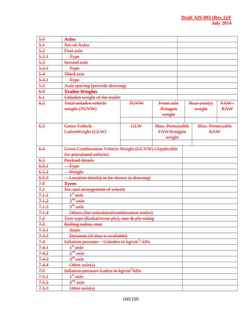
Draft AIS-093 (Rev.1)/F
July 2014
160/169
5.0 Axles
5.1 No. of Axles
5.2 First axle
5.2.1 Type
5.3 Second axle
5.3.1 Type
5.4 Third axle
5.4.1 Type
5.5 Axle spacing (provide drawing)
6.0 Trailer Weights
6.1 Unladen weight of the trailer
6.2 Total unladen vehicle
weight (TUVW)
TUVW Front axle
/Kingpin
weight
Rear axle(s)
weight
FAW /
RAW
6.3 Gross Vehicle
LadenWeight (GLW)
GLW Max. Permissible
FAW/Kingpin
weight
Max. Permissible
RAW
6.4 Gross Combination Vehicle Weight (GCVW) (Applicable
for articulated vehicle)
6.5 Payload details
6.5.1 Type
6.5.2 Weight
6.5.3 Location details( to be shown in drawing)
7.0 Tyres
7.1 No. and arrangement of wheels
7.1.1 1st axle
7.1.2 2nd
axle
7.1.3 3rd
axle
7.1.4 Others (for articulated/combination trailer)
7.2 Tyre type (Radial/cross ply), size & ply rating
7.3 Rolling radius, mm
7.3.1 Static
7.3.2 Dynamic (if data is available)
7.4 Inflation pressure – Unladen in kg/cm2/ kPa
7.4.1 1st axle
7.4.2 2nd
axle
7.4.3 3rd
axle
7.4.4 Other axle(s)
7.5 Inflation pressure-Laden in kg/cm2/kPa
7.5.1 1st axle
7.5.2 2nd
axle
7.5.3 Other axle(s)
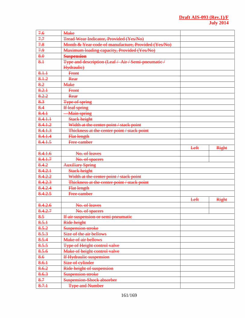
Draft AIS-093 (Rev.1)/F
July 2014
161/169
7.6 Make
7.7 Tread Wear Indicator, Provided (Yes/No)
7.8 Month & Year code of manufacture, Provided (Yes/No)
7.9 Maximum loading capacity, Provided (Yes/No)
8.0 Suspension
8.1 Type and description (Leaf / Air / Semi-pneumatic /
Hydraulic)
8.1.1 Front
8.1.2 Rear
8.2 Make
8.2.1 Front
8.2.2 Rear
8.3 Type of spring
8.4 If leaf spring
8.4.1 Main spring
8.4.1.1 Stack height
8.4.1.2 Width at the center point / stack point
8.4.1.3 Thickness at the center point / stack point
8.4.1.4 Flat length
8.4.1.5 Free camber
Left Right
8.4.1.6 No. of leaves
8.4.1.7 No. of spacers
8.4.2 Auxiliary Spring
8.4.2.1 Stack height
8.4.2.2 Width at the center point / stack point
8.4.2.3 Thickness at the center point / stack point
8.4.2.4 Flat length
8.4.2.5 Free camber
Left Right
8.4.2.6 No. of leaves
8.4.2.7 No. of spacers
8.5 If air suspension or semi pneumatic
8.5.1 Ride height
8.5.2 Suspension stroke
8.5.3 Size of the air bellows
8.5.4 Make of air bellows
8.5.5 Type of Height control valve
8.5.6 Make of height control valve
8.6 If Hydraulic suspension
8.6.1 Size of cylinder
8.6.2 Ride height of suspension
8.6.3 Suspension stroke
8.7 Suspension-Shock absorber
8.7.1 Type and Number

Draft AIS-093 (Rev.1)/F
July 2014
162/169
8.7.1.1 Front
8.7.1.2 Rear
8.8 Suspension configuration-Single/Tandem/Tridem
8.9 Any load equalizing device provided
9.0 Rear Under run Protective device
9.1 Height of lower edge of the device from the ground (mm)
9.2 Width of the device (mm)
9.3 Drawing of the rear under-run protective device with
dimensions. (Including part drawing)
9.4 Material (Metal/Fiber/etc.)
10.0 Lateral Protection (Side Guards)
10.1 Height of the lower edge of the Side Guard.
10.2 Drawing of the lateral protection device fitted on the
vehicle with dimensions
10.3 Material (Metal/Fiber/etc.)
11.0 Chassis Frame
11.1 Type
11.2 Drawing with dimensions
11.3 Type of platform
12.0 Brakes
12.1 Type and Brief Description
12.2 Service brakes
12.2.1 Name of producer
12.2.2 Type (Mechanical/hydraulic/air assisted/ vacuum
assisted/others)
12.2.3 Control system & braking wheel
12.2.4 Schematic layout indicating method of split of brake
system, location of valves, reservoirs etc.
12.3 Anti-Lock braking system Provided (Yes/No)
12.3.1 If yes, details
12.3.2 ABS make
12.4 Electronic Control Unit (ECU)
12.4.1 Make
12.4.2 Identification mark
12.5 Wheel Speed Sensor
12.5.1 Make
12.5.2 Identification mark
12.5.3 No. of sensors used
12.6 Hydraulic Modulator
12.6.1 Make
12.6.2 Identification mark
12.7 Solenoid Valve
12.7.1 Make
12.7.2 Identification mark
12.7.3 Max. designed pressure, kg/cm2
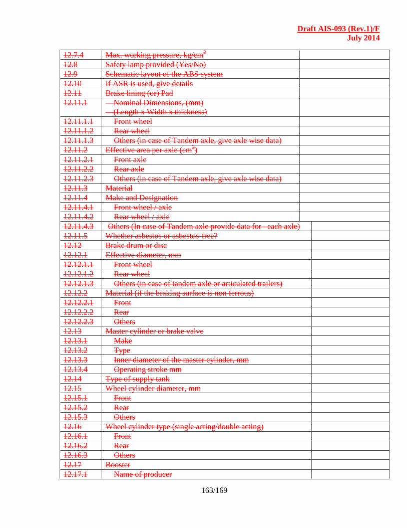
Draft AIS-093 (Rev.1)/F
July 2014
163/169
12.7.4 Max. working pressure, kg/cm2
12.8 Safety lamp provided (Yes/No)
12.9 Schematic layout of the ABS system
12.10 If ASR is used, give details
12.11 Brake lining (or) Pad
12.11.1 Nominal Dimensions, (mm)
(Length x Width x thickness)
12.11.1.1 Front wheel
12.11.1.2 Rear wheel
12.11.1.3 Others (in case of Tandem axle, give axle wise data)
12.11.2 Effective area per axle (cm2)
12.11.2.1 Front axle
12.11.2.2 Rear axle
12.11.2.3 Others (in case of Tandem axle, give axle wise data)
12.11.3 Material
12.11.4 Make and Designation
12.11.4.1 Front wheel / axle
12.11.4.2 Rear wheel / axle
12.11.4.3 Others (In case of Tandem axle provide data for each axle)
12.11.5 Whether asbestos or asbestos-free?
12.12 Brake drum or disc
12.12.1 Effective diameter, mm
12.12.1.1 Front wheel
12.12.1.2 Rear wheel
12.12.1.3 Others (in case of tandem axle or articulated trailers)
12.12.2 Material (if the braking surface is non ferrous)
12.12.2.1 Front
12.12.2.2 Rear
12.12.2.3 Others
12.13 Master cylinder or brake valve
12.13.1 Make
12.13.2 Type
12.13.3 Inner diameter of the master cylinder, mm
12.13.4 Operating stroke mm
12.14 Type of supply tank
12.15 Wheel cylinder diameter, mm
12.15.1 Front
12.15.2 Rear
12.15.3 Others
12.16 Wheel cylinder type (single acting/double acting)
12.16.1 Front
12.16.2 Rear
12.16.3 Others
12.17 Booster
12.17.1 Name of producer
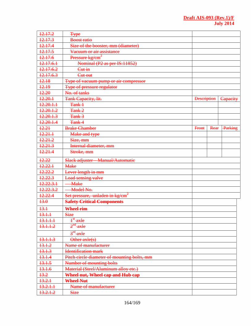
Draft AIS-093 (Rev.1)/F
July 2014
164/169
12.17.2 Type
12.17.3 Boost ratio
12.17.4 Size of the booster, mm (diameter)
12.17.5 Vacuum or air assistance
12.17.6 Pressure kg/cm2
12.17.6.1 Nominal (P2 as per IS:11852)
12.17.6.2 Cut in
12.17.6.3 Cut out
12.18 Type of vacuum pump or air compressor
12.19 Type of pressure regulator
12.20 No. of tanks
12.20.1 Tank Capacity, lit. Description Capacity
12.20.1.1 Tank 1
12.20.1.2 Tank 2
12.20.1.3 Tank 3
12.20.1.4 Tank 4
12.21 Brake Chamber Front Rear Parking
12.21.1 Make and type
12.21.2 Size, mm
12.21.3 Internal diameter, mm
12.21.4 Stroke, mm
12.22 Slack adjuster – Manual/Automatic
12.22.1 Make
12.22.2 Lever length in mm
12.22.3 Load sensing valve
12.22.3.1 Make
12.22.3.2 Model No.
12.22.4 Set pressure, unladen in kg/cm2
13.0 Safety Critical Components
13.1 Wheel rim
13.1.1 Size
13.1.1.1 1st axle
13.1.1.2 2nd
axle
3rd
axle
13.1.1.3 Other axle(s)
13.1.2 Name of manufacturer
13.1.3 Identification mark
13.1.4 Pitch circle diameter of mounting bolts, mm
13.1.5 Number of mounting bolts
13.1.6 Material (Steel/Aluminum alloy etc.)
13.2 Wheel nut, Wheel cap and Hub cap
13.2.1 Wheel Nut
13.2.1.1 Name of manufacturer
13.2.1.2 Size
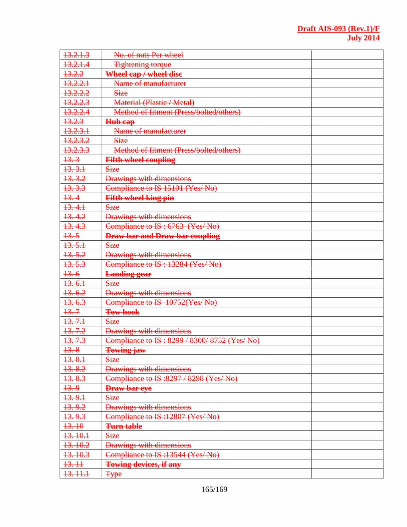
Draft AIS-093 (Rev.1)/F
July 2014
165/169
13.2.1.3 No. of nuts Per wheel
13.2.1.4 Tightening torque
13.2.2 Wheel cap / wheel disc
13.2.2.1 Name of manufacturer
13.2.2.2 Size
13.2.2.3 Material (Plastic / Metal)
13.2.2.4 Method of fitment (Press/bolted/others)
13.2.3 Hub cap
13.2.3.1 Name of manufacturer
13.2.3.2 Size
13.2.3.3 Method of fitment (Press/bolted/others)
13. 3 Fifth wheel coupling
13. 3.1 Size
13. 3.2 Drawings with dimensions
13. 3.3 Compliance to IS 15101 (Yes/ No)
13. 4 Fifth wheel king pin
13. 4.1 Size
13. 4.2 Drawings with dimensions
13. 4.3 Compliance to IS : 6763 (Yes/ No)
13. 5 Draw bar and Draw bar coupling
13. 5.1 Size
13. 5.2 Drawings with dimensions
13. 5.3 Compliance to IS : 13284 (Yes/ No)
13. 6 Landing gear
13. 6.1 Size
13. 6.2 Drawings with dimensions
13. 6.3 Compliance to IS 10752(Yes/ No)
13. 7 Tow hook
13. 7.1 Size
13. 7.2 Drawings with dimensions
13. 7.3 Compliance to IS : 8299 / 8300/ 8752 (Yes/ No)
13. 8 Towing jaw
13. 8.1 Size
13. 8.2 Drawings with dimensions
13. 8.3 Compliance to IS :8297 / 8298 (Yes/ No)
13. 9 Draw bar eye
13. 9.1 Size
13. 9.2 Drawings with dimensions
13. 9.3 Compliance to IS :12807 (Yes/ No)
13. 10 Turn table
13. 10.1 Size
13. 10.2 Drawings with dimensions
13. 10.3 Compliance to IS :13544 (Yes/ No)
13. 11 Towing devices, if any
13. 11.1 Type
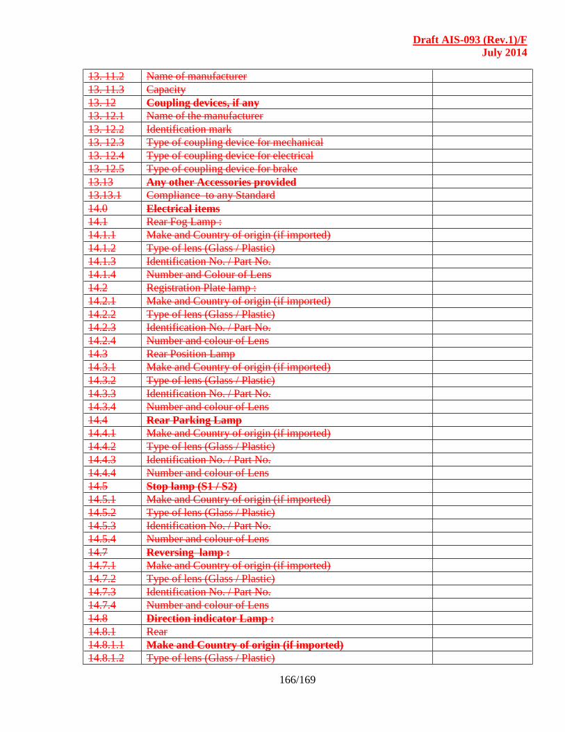
Draft AIS-093 (Rev.1)/F
July 2014
166/169
13. 11.2 Name of manufacturer
13. 11.3 Capacity
13. 12 Coupling devices, if any
13. 12.1 Name of the manufacturer
13. 12.2 Identification mark
13. 12.3 Type of coupling device for mechanical
13. 12.4 Type of coupling device for electrical
13. 12.5 Type of coupling device for brake
13.13 Any other Accessories provided
13.13.1 Compliance to any Standard
14.0 Electrical items
14.1 Rear Fog Lamp :
14.1.1 Make and Country of origin (if imported)
14.1.2 Type of lens (Glass / Plastic)
14.1.3 Identification No. / Part No.
14.1.4 Number and Colour of Lens
14.2 Registration Plate lamp :
14.2.1 Make and Country of origin (if imported)
14.2.2 Type of lens (Glass / Plastic)
14.2.3 Identification No. / Part No.
14.2.4 Number and colour of Lens
14.3 Rear Position Lamp
14.3.1 Make and Country of origin (if imported)
14.3.2 Type of lens (Glass / Plastic)
14.3.3 Identification No. / Part No.
14.3.4 Number and colour of Lens
14.4 Rear Parking Lamp
14.4.1 Make and Country of origin (if imported)
14.4.2 Type of lens (Glass / Plastic)
14.4.3 Identification No. / Part No.
14.4.4 Number and colour of Lens
14.5 Stop lamp (S1 / S2)
14.5.1 Make and Country of origin (if imported)
14.5.2 Type of lens (Glass / Plastic)
14.5.3 Identification No. / Part No.
14.5.4 Number and colour of Lens
14.7 Reversing lamp :
14.7.1 Make and Country of origin (if imported)
14.7.2 Type of lens (Glass / Plastic)
14.7.3 Identification No. / Part No.
14.7.4 Number and colour of Lens
14.8 Direction indicator Lamp :
14.8.1 Rear
14.8.1.1 Make and Country of origin (if imported)
14.8.1.2 Type of lens (Glass / Plastic)

Draft AIS-093 (Rev.1)/F
July 2014
167/169
14.8.1.3 Identification No. / Part No.
14.8.1.4 Number and colour of Lens
14.8.2 Side
14.8.2.1 Make and Country of origin (if imported)
14.8.2.2 Type of lens (Glass / Plastic)
14.8.2.3 Identification No. / Part No.
14.8.2.4 Number and colour of Lens
14.8.3 Type of flasher
14.9 Hazard warning signal :
14.9.1 Rear
14.9.1.1 Make and Country of origin (if imported)
14.9.1.2 Type of lens (Glass / Plastic)
14.9.1.3 Identification No. / Part No.
14.9.1.4 Number and colour of Lens
14.9.2 Side
14.9.2.1 Make and Country of origin (if imported)
14.9.2.2 Type of lens (Glass / Plastic)
14.9.2.3 Identification No. / Part No.
14.9.2.4 Number and colour of Lens
14.10 Reflector :
14.10.1 Rear
14.10.1.1 Make and Country of origin (if imported)
14.10.1.2 Type
14.10.1.3 Identification No. / Part No.
14.10.1.4 Number and colour of Lens
14.10.1.5 Area
14.10.1.6 Shape
14.10.2 Side
14.10.2.1 Make and Country of origin (if imported)
14.10.2.2 Type
14.10.2.3 Identification No. / Part No.
14.10.2.4 Number and colour of Lens
14.10.2.5 Area
14.10.2.6 Shape
14.11 End – outline marker lamp (Top light)
14.11.1 Rear
14.11.1.1 Make and Country of origin (if imported)
14.11.1.2 Type of lens (Glass / Plastic)
14.11.1.3 Identification No. / Part No.
14.11.1.4 Number and colour of Lens
14.12 Diagram of vehicle indicating location, reference axis, mark of
apparent surface, contour of vehicle parts limiting geometric
visibility of all lights and light signaling devices, location of
extreme outer edges and longitudinal median plane of vehicle
including following dimensions in mm.
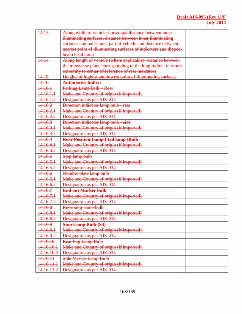
Draft AIS-093 (Rev.1)/F
July 2014
168/169
14.13 Along width of vehicle-horizontal distance between inner
illuminating surfaces, distance between inner illuminating
surfaces and outer most part of vehicle and distance between
nearest point of illuminating surfaces of indicators and dipped-
beam head lamp
14.14 Along length of vehicle (where applicable)- distance between
the transverse plane corresponding to the longitudinal rearmost
extremity to center of reference of rear indicators
14.15 Heights of highest and lowest point of illuminating surfaces
14.16 Automotive bulbs :
14.16.1 Parking Lamp bulb – Rear
14.16.1.1 Make and Country of origin (if imported)
14.16.1.2 Designation as per AIS-034
14.16.2 Direction indicator lamp bulb - rear
14.16.2.1 Make and Country of origin (if imported)
14.16.2.2 Designation as per AIS-034
14.16.3 Direction indicator lamp bulb - side
14.16.3.1 Make and Country of origin (if imported)
14.16.3.2 Designation as per AIS-034
14.16.4 Rear Position Lamp ( tail lamp )Bulb
14.16.4.1 Make and Country of origin (if imported)
14.16.4.2 Designation as per AIS-034
14.16.5 Stop lamp bulb
14.16.5.1 Make and Country of origin (if imported)
14.16.5.2 Designation as per AIS-034
14.16.6 Number plate lamp bulb
14.16.6.1 Make and Country of origin (if imported)
14.16.6.2 Designation as per AIS-034
14.16.7 End out Marker bulb
14.16.7.1 Make and Country of origin (if imported)
14.16.7.2 Designation as per AIS-034
14.16.8 Reversing lamp bulb
14.16.8.1 Make and Country of origin (if imported)
14.16.8.2 Designation as per AIS-034
14.16.9 Stop Lamp Bulb (S3)
14.16.9.1 Make and Country of origin (if imported)
14.16.9.2 Designation as per AIS-034
14.16.10 Rear Fog Lamp Bulb
14.16.10.1 Make and Country of origin (if imported)
14.16.10.2 Designation as per AIS-034
14.16.11 Side Marker Lamp Bulb
14.16.11.1 Make and Country of origin (if imported)
14.16.11.2 Designation as per AIS-034
Draft AIS-093 (Rev.1)/F
July 2014
169/169
Annexure – III
COMPOSITION OF THE SUB-COMMITTEE OF
CMVR-TECHNICAL STANDING COMMITTEE
(To be included)