
Code 3Check® Electrical 6th Edition - Code · PDF filestill uses the 2008 NEC, look in the...
5
INTRODUCTION u CODES u ABBREVIATIONS In 1752, Benjamin Franklin, aided by his son, William, conducted the famous, but highly dangerous kite experiment. For an animated explanation, visit: www. codecheck.com/cc/BenAndTheKite.html Code 3 Check ® Electrical 6th Edition BY REDWOOD KARDON & DOUGLAS HANSEN Illustrations & Layout: Paddy Morrissey © 2010 by The Taunton Press, Inc. ISBN 978-1-60085-012-7 Code Check® is a registered trademark of The Taunton Press, Inc., registered in the U.S. Patent & Trademark Office. For information on code adoptions by state, and more information on building, plumbing, electrical, and mechanical codes, visit: www.codecheck.com Printed in China C ode Check Electrical is a field guide to common code issues in residential electrical installations. It is based on the 2011 National Electrical Code —the most widely used electrical code in the United States—and the 2009 International Residential Code. Before beginning any electrical project, check with your local building department. In addition to a model code, energy codes and special rules from utility companies could also apply. Each code line in Code Check Electrical references the two codes named above. Many building jurisdictions use older versions of the codes. If you are in an area that still uses the 2008 NEC, look in the “09 IRC” column of code references to see if the item applies in your area, and use the table on the inside back cover to see changes that were made in the 2008 NEC, 2009 IRC, and 2011 NEC. In places where the IRC does not reference a particular rule, the NEC rule might still apply, even where the IRC code is adopted. The IRC states that items not specifical- ly mentioned in that code should comply with the NEC. This applies to issues such as old wiring, outside feeders, and photovoltaics, which are not covered in the IRC. For information on electrical fundamentals and theory, visit: http://www.codecheck.com/cc/OhmsLaw.html HOW TO USE CODE CHECK ELECTRICAL Each text line ends with two code citations. The code numbers on the left, with straight brackets, refer to the 2009 IRC. The code numbers on the right, in braces, refer to the 2011 NEC. For example (from p. 4): n Max 6 disconnects to shut off power _________________ [3601.7] {230.71} This line states that there can be no more than 6 disconnects to shut off power, and the rule is found in 3601.7 of the IRC and 230.71 of the NEC. An “n/a” in a code line means the rule is not applicable to that particular code. An “EXC” at the end of a line means that an exception—or exceptions—to the rule will follow in the next line, for example (from p. 12): n Backfed breakers secured in place EXC______________ [3706.5] {408.36D} • Output circuits from utility interactive PV inverter _________[n/a] {705.12D6} Backfed breakers must be secured in place per IRC 3606.5 & NEC 408.36, except that the NEC has an exception for photovoltaic circuits from an inverter. The “n/a” in the IRC column tells us this rule does not apply to that code. The list of ab- breviations (to the right on this page) tells us that PV = photovoltaic. Significant code changes are highlighted by a different color for their code citation, and the superscript note after them refers to the list on the inside back cover, for example (from p. 12): from p. 16): n GFCIs req’d to be in readily accessible locations __________[n/a] {210.8A} 19 GFCI devices must be located in an area where they remain readily accessible (see definition in glossary on page 3). The rule is not in the IRC and in the NEC it is a change in the 2011 code, summarized as change #19 on the inside back cover T23. Text lines ending in “OR” mean that an alternative rule follows in the next line, for example (from p. 17): n Separate 20A circuit for bath receptacles only OR _____ [3703.4] {210.11C3} • Dedicated 20A circuit to each bathroom ___________ [3703.4X] {210.11C3X} A separate 20-amp circuit must be supplied for no other purpose than the bathroom receptacles. Alternatively, each bathroom can be supplied with its own 20-amp circuit, and then other outlets in that bathroom (such as lights) could be on the circuit. Based on the 2011 NEC ® and the 2009 IRC ® ABBREVIATIONS A = amp, amperage, amps, such as a 15A breaker AC = air conditioning AC = alternating current AC = armored cable, a.k.a. “BX” AFCI = arc-fault circuit interrupter AHJ = Authority Having Jurisdiction Al = aluminum AMI = in accordance with manufacturer’s instructions AWG = American Wire Gauge CATV = cable television CO = Carbon Monoxide Cu = copper DC = direct current EGC = equipment grounding conductor EMT = electrical metallic tubing ENT = electrical nonmetallic tubing, a.k.a. “Smurf tubing” EV= Electric Vehicle EXC = exception(s) FMC = flexible metal conduit (“Greenfield”) ft = foot, feet GEC = grounding electrode conductor GES = grounding electrode system GFCI = ground-fault circuit interrupter GFPE = ground-fault protection of equipment hp = horsepower (33,000 lb.ft./minute) IMC = intermediate metal conduit in = inch, inches IRC = International Residential Code kcmil = 1,000 circular mil units (conductor size) L&L = listed & labeled, listing & labeling lb = pound, pounds LFMC = liquidtight flexible metal conduit, a.k.a. “Sealtight” LFNMC = liquidtight flexible nonmetallic conduit manu = manufacturer MC = metal-clad cable max = maximum min = minimum NEC = National Electrical Code NFPA = National Fire Protection Associa- tion NM = nonmetallic-sheathed cable OCPD = overcurrent protection device (breaker or fuse) PV = photovoltaic PVC = rigid polyvinyl chloride conduit req = require, requiring, requirement req’d = required req’s = requires RMC = rigid metal conduit SCCR = short circuit rating SE = service entrance cable SFD = single-family dwelling sq = square temp = temperature UF = underground feeder cable USE = underground service entrance cable V = volt, volts, such as a 120V circuit VA = volt-amperes, units of apparent power w/ = with; w/o = without W = watts, units of true (useful) power
Transcript of Code 3Check® Electrical 6th Edition - Code · PDF filestill uses the 2008 NEC, look in the...

INTRODUCTION u CODES u ABBREVIATIONS
In 1752, Benjamin Franklin, aided by his son, William, conducted the famous, but highly dangerous kite
experiment. For an animated explanation, visit: www.codecheck.com/cc/BenAndTheKite.html
Code 3Check® Electrical 6th Edition
By Redwood KaRdon & doUGLaS HanSenIllustrations & Layout: Paddy Morrissey
© 2010 by The Taunton Press, Inc. ISBN 978-1-60085-012-7Code Check® is a registered trademark of The Taunton Press, Inc., registered in the U.S. Patent & Trademark Office.
For information on code adoptions by state, and more information on building, plumbing, electrical, and mechanical codes, visit: www.codecheck.com
Printed in China
Code Check electrical is a field guide to common code issues in residential electrical installations. It is based on the 2011 national electrical Code —the most widely used electrical code in the United States—and the 2009
International Residential Code. Before beginning any electrical project, check with your local building department. In addition to a model code, energy codes and special rules from utility companies could also apply.
Each code line in Code Check electrical references the two codes named above. Many building jurisdictions use older versions of the codes. If you are in an area that still uses the 2008 NEC, look in the “09 IRC” column of code references to see if the item applies in your area, and use the table on the inside back cover to see changes that were made in the 2008 neC, 2009 IRC, and 2011 neC.In places where the IRC does not reference a particular rule, the NEC rule might still apply, even where the IRC code is adopted. The IRC states that items not specifical-ly mentioned in that code should comply with the NEC. This applies to issues such as old wiring, outside feeders, and photovoltaics, which are not covered in the IRC.
For information on electrical fundamentals and theory, visit:http://www.codecheck.com/cc/OhmsLaw.html
How To USe Code CHeCK eLeCTRICaLEach text line ends with two code citations. The code numbers on the left, with straight brackets, refer to the 2009 IRC. The code numbers on the right, in braces, refer to the 2011 NEC. For example (from p. 4):
n Max 6 disconnects to shut off power _________________ [3601.7] {230.71}
This line states that there can be no more than 6 disconnects to shut off power, and the rule is found in 3601.7 of the IRC and 230.71 of the NEC.
An “n/a” in a code line means the rule is not applicable to that particular code.An “EXC” at the end of a line means that an exception—or exceptions—to the rule will follow in the next line, for example (from p. 12):
n Backfed breakers secured in place EXC ______________ [3706.5] {408.36D} •OutputcircuitsfromutilityinteractivePVinverter _________[n/a] {705.12D6}
Backfed breakers must be secured in place per IRC 3606.5 & NEC 408.36, except that the NEC has an exception for photovoltaic circuits from an inverter. The “n/a” in the IRC column tells us this rule does not apply to that code. The list of ab-breviations (to the right on this page) tells us that PV = photovoltaic.
Significant code changes are highlighted by a different color for their code citation, and the superscript note after them refers to the list on the inside back cover, for example (from p. 12): from p. 16):
n GFCIs req’d to be in readily accessible locations __________[n/a] {210.8A}19
GFCI devices must be located in an area where they remain readily accessible (see definition in glossary on page 3). The rule is not in the IRC and in the NEC it is a change in the 2011 code, summarized as change #19 on the inside back cover T23.
Text lines ending in “OR” mean that an alternative rule follows in the next line, for example (from p. 17):
n Separate 20A circuit for bath receptacles only OR _____ [3703.4] {210.11C3} •Dedicated20Acircuittoeachbathroom ___________ [3703.4X] {210.11C3X}
A separate 20-amp circuit must be supplied for no other purpose than the bathroom receptacles. Alternatively, each bathroom can be supplied with its own 20-amp circuit, and then other outlets in that bathroom (such as lights) could be on the circuit.
Based on the 2011 NEC® and the 2009 IRC®
aBBRevIaTIonS
a = amp, amperage, amps, such as a 15A breakeraC = air conditioningaC = alternating current aC = armored cable, a.k.a. “BX”aFCI = arc-fault circuit interrupteraHJ = Authority Having Jurisdictional = aluminumaMI = in accordance with manufacturer’s instructionsawG = American Wire GaugeCaTv = cable televisionCo = Carbon MonoxideCu = copperdC = direct currenteGC = equipment grounding conductoreMT = electrical metallic tubingenT = electrical nonmetallic tubing, a.k.a. “Smurf tubing”ev=ElectricVehicleeXC = exception(s)FMC = flexible metal conduit (“Greenfield”)ft = foot, feetGeC = grounding electrode conductorGeS = grounding electrode systemGFCI = ground-fault circuit interrupterGFPe = ground-fault protection of equipmenthp = horsepower (33,000 lb.ft./minute)IMC = intermediate metal conduitin = inch, inchesIRC = International Residential Codekcmil = 1,000 circular mil units (conductor size)
L&L = listed & labeled, listing & labelinglb = pound, poundsLFMC = liquidtight flexible metal conduit, a.k.a. “Sealtight”LFnMC = liquidtight flexible nonmetallic conduitmanu = manufacturerMC = metal-clad cablemax = maximummin = minimumneC = National Electrical CodenFPa = National Fire Protection Associa-tionnM = nonmetallic-sheathed cable oCPd = overcurrent protection device (breaker or fuse)Pv = photovoltaicPvC = rigid polyvinyl chloride conduitreq = require, requiring, requirementreq’d = requiredreq’s = requiresRMC = rigid metal conduitSCCR = short circuit ratingSe = service entrance cableSFd = single-family dwellingsq = squaretemp = temperatureUF = underground feeder cableUSe = underground service entrance cablev=volt,volts,suchasa120Vcircuitva = volt-amperes, units of apparent powerw/ = with; w/o = withoutw = watts, units of true (useful) power
SERVICES 3
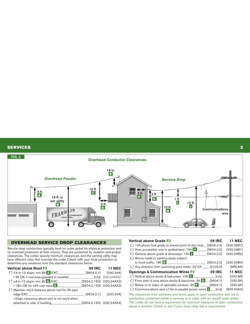
OVERhEAD SERVICE DROp CLEARANCESService drop conductors typically have no outer jacket for physical protection and no overload protection at their source. They are protected by isolation and proper clearances. The codes specify minimum clearances, and the serving utility may have different rules that override the code. Check with your local jurisdiction to determine any variations from the standard clearances below.
vertical above Roof F2 09 IRC 11 neCn <4-in-12 slope: min 8ft .a EXC ________________ [3604.2.1] {230.24A} •3ftOKifroofareaguardedorisolated _______________[n/a] {230.24AX5}1
n ≥4-in-12 slope: min 3ft .G EXC ______________ [3604.2.1X2] {230.24AX2} •18inOKfor≤4ft over eave .e ______________ [3604.2.1X3] {230.24AX3}n Maintain req’d distance above roof for 3ft past edge EXC __________________________________ [3604.2.1] {230.24A} •Edgeclearanceaboveroofisnotreq’dwhen attached to side of building __________________ [3604.2.1X4] {230.24AX4}
vertical above Grade F2 09 IRC 11 neCn 10ft above final grade to lowest point of drip loop _ [3604.2.2] {230.24B1}n Area accessible only to pedestrians: 10ft .H _____ [3604.2.2] {230.24B1}n General above grade & driveways: 12ft .J _______ [3604.2.2] {230.24B2}n Above roads or parking areas subject to truck traffic: 18ft .B _______________________ [3604.2.2] {230.24B4}n Any direction from swimming pool water: 221/2ft ____ [4103.5] {680.8A}
openings & Communication wires F2 09 IRC 11 neCn Verticalabovedecks&balconies:10ft.C _____________[n/a] {230.9B}n From side of area above decks & balconies: 3ft .d __ [3604.1] {230.9A}n Below or to sides of openable window: 3ft .F ______ [3604.1] {230.9A}n Communications wire ≥12in to parallel power wires .I ___[n/a] {800.44A4}
The clearances from windows and doors apply to open conductors and not to conductors contained inside a raceway or a cable with an overall outer jacket. The codes do not have a requirement for minimum clearance of open conductors above a window. Check to see if your local utility has a requirement.
FIG. 2overhead Conductor Clearances
3 ft..D
18 ft. or per utility
.B
10 ft..C 3 ft.
.G
3 ft..F
18 in..E
10 ft..h
1 ft..I 12 ft.
.J
8 ft..A
Service Drop
Communicationswire
Overhead Feeder
GROUNDING 10
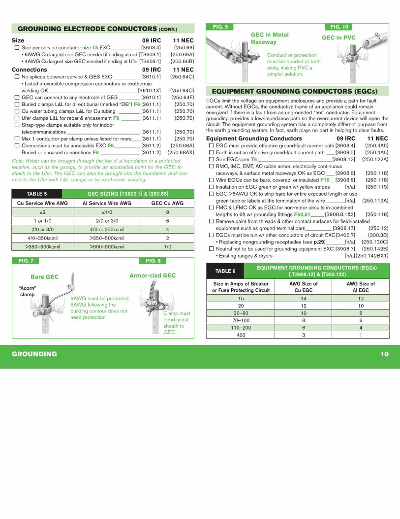
EqUIpmENT GROUNDING CONDUCTORS (EGCS)EGCs limit the voltage on equipment enclosures and provide a path for fault current. Without EGCs, the conductive frame of an appliance could remain energized if there is a fault from an ungrounded “hot” conductor. Equipment grounding provides a low-impedance path so the overcurrent device will open the circuit. The equipment grounding system has a completely different purpose from the earth grounding system. In fact, earth plays no part in helping to clear faults.
equipment Grounding Conductors 09 IRC 11 neCn EGC must provide effective ground-fault current path [3908.4] {250.4A5}n Earth is not an effective ground-fault current path ___ [3908.5] {250.4A5}n Size EGCs per T6 ____________________________[3908.12] {250.122A}n RMC, IMC, EMT, AC cable armor, electrically continuous raceways,&surfacemetalracewaysOKasEGC ___ [3908.8] {250.118}n Wire EGCs can be bare, covered, or insulated F16 _ [3908.8] {250.118}n Insulation on EGC green or green w/ yellow stripes _____[n/a] {250.119}n EGC>6AWGOKtostripbareforentireexposedlengthoruse green tape or labels at the termination of the wire _______[n/a] {250.119A}n FMC&LFMCOKasEGCfornon-motorcircuitsincombined lengths to 6ft w/ grounding fittings F60,61 _____ [3908.8.1&2] {250.118}n Remove paint from threads & other contact surfaces for field-installed equipment such as ground terminal bars __________ [3908.17] {250.12}n EGCs must be run w/ other conductors of circuit EXC [3406.7] {300.3B} •Replacingnongroundingreceptacles(seep.29) _______[n/a] {250.130C}n Neutral not to be used for grounding equipment EXC [3908.7] {250.142B} •Existingranges&dryers ___________________________[n/a] {250.142BX1}
GROUNDING ELECTRODE CONDUCTORS (CONT.)
Size 09 IRC 11 neCn Size per service conductor size T5 EXC ___________ [3603.4] {250.66} •6AWGCulargestsizeGECneededifendingatrod [T3603.1] {250.66A} •4AWGCulargestsizeGECneededifendingatUfer [T3603.1] {250.66B}
Connections 09 IRC 11 neCn No splices between service & GES EXC __________ [3610.1] {250.64C} •Listedirreversiblecompressionconnectorsorexothermic weldingOK __________________________________[3610.1X] {250.64C}n GEC can connect to any electrode of GES ________ [3610.1] {250.64F}n Buried clamps L&L for direct burial (marked “DB”) F6 [3611.1] {250.70}n Cu water tubing clamps L&L for Cu tubing ________ [3611.1] {250.70}n Ufer clamps L&L for rebar & encasement F6 _______ [3611.1] {250.70}n Strap-type clamps suitable only for indoor telecommunications ____________________________ [3611.1] {250.70}n Max 1 conductor per clamp unless listed for more ___ [3611.1] {250.70}n Connections must be accessible EXC F6 __________ [3611.2] {250.68A} Buried or encased connections F6 _______________ [3611.2] {250.68AX}
Note: Rebar can be brought through the top of a foundation in a protectedlocation, such as the garage, to provide an accessible point for the GEC to attach to the Ufer. The GEC can also be brought into the foundation and con-nect to the Ufer with L&L clamps or by exothermic welding.
TABlE 5 GEC SIzING [T3603.1] & {250.66}
Cu Service Wire AWG Al Service Wire AWG GEC Cu AWG
≤2 ≤1/0 8
1 or 1/0 2/0 or 3/0 6
2/0 or 3/0 4/0 or 250kcmil 4
4/0–350kcmil >250–500kcmil 2
>350–600kcmil >500–900kcmil 1/0
FIG. 8
TaBLe 6 eqUIPMenT GRoUndInG CondUCToRS (eGCs)
[ T3908.12] & {T250.122}
Size in Amps of Breaker or Fuse Protecting Circuit
AWG Size ofCu EGC
AWG Size ofAl EGC
15 14 1220 12 10
30–60 10 870–100 8 6
110–200 6 4400 3 1
“Acorn” clamp
Bare GeC
FIG. 7
armor-clad GeC
8AWG must be protected. 6AWG following the building contour does not need protection.
Clamp must bond metal sheath to GEC
GeC in Metal Raceway
FIG. 9
Conductive protection must be bonded at both ends,makingPVCasimpler solution.
FIG. 10
GeC in PvC
BONDING u pANELS 11
BONDINGBonding ensures electrical continuity to limit voltage potential between conduc-tive components. On the line side (ahead of the main disconnect F15), it pro-vides a path back to the utility transformer for faults on service conductors and to limitvoltagepotentialtoothersystems,suchastelephonesorcableTV.Ontheload side (after the main overcurrent protection F15), bonding and equipment grounding provide a path to clear faults and protect against shocks.
Bonding & equipment Grounding Methods 09 IRC 11 neCn Use listed connectors, terminal bars, exothermic welding, machine screws engaging 2 threads or secured w/ nut, or thread-forming machine screws engaging 2 threads - no sheet metal or drywall screws ______________________________ [3908.15]6 {250.8A}n Connections may not depend solely on solder _____[3908.13] {250.8B}n Clean nonconductive coatings from contact surfaces [3908.17] {250.12}
Line-Side Bonding F11,12,15 09 IRC 11 neCn Bond all service equipment, raceways, & cable armor [3609.2] {250.92A}n Bond metal GEC enclosures at each end _________ [T3603.1] {250.64E}n ThreadedfittingsOKforbondingserviceconduit _ [3609.4.2] {250.92B2}n MeyershubOKforbondingserviceconduitF11 __ [3609.4.2] {250.92B2}n Standard locknuts alone not sufficient on line side of service F11 ____________________ [3609.4.3] {250.92B2}n BondinglocknutsOKifnoremainingconcentricsF11 [3609.4.4] {250.92B4}n Jumpers req’d around concentric knockouts, or reducing washers on line side of service F12,15 __________________ [3609.4.4] {250.92B4}7
n Service neutral can bond line-side equipment ____ [3609.4.1] {250.142A}n Size line-side bonding jumpers per T5 _____________ [3609.5] {250.102C}n Service enclosure main bonding jumper must connect enclosure, service neutral, & equipment grounds F15 _________ [3607.5] {250.24B}
Load-Side Bonding 09 IRC 11 neCn Bond any metal piping system capable of becoming energized, including hot & cold water & gas F13 _ [3609.6&7] {250.104}n Size water pipe bonding per T5 __________________ [3609.6] {250.104A1}n Size gas pipe bonding per T6 ____________________ [3609.7] {250.104B}n Bond metal well casings to EGC of pump motor ________[n/a] {250.112M}
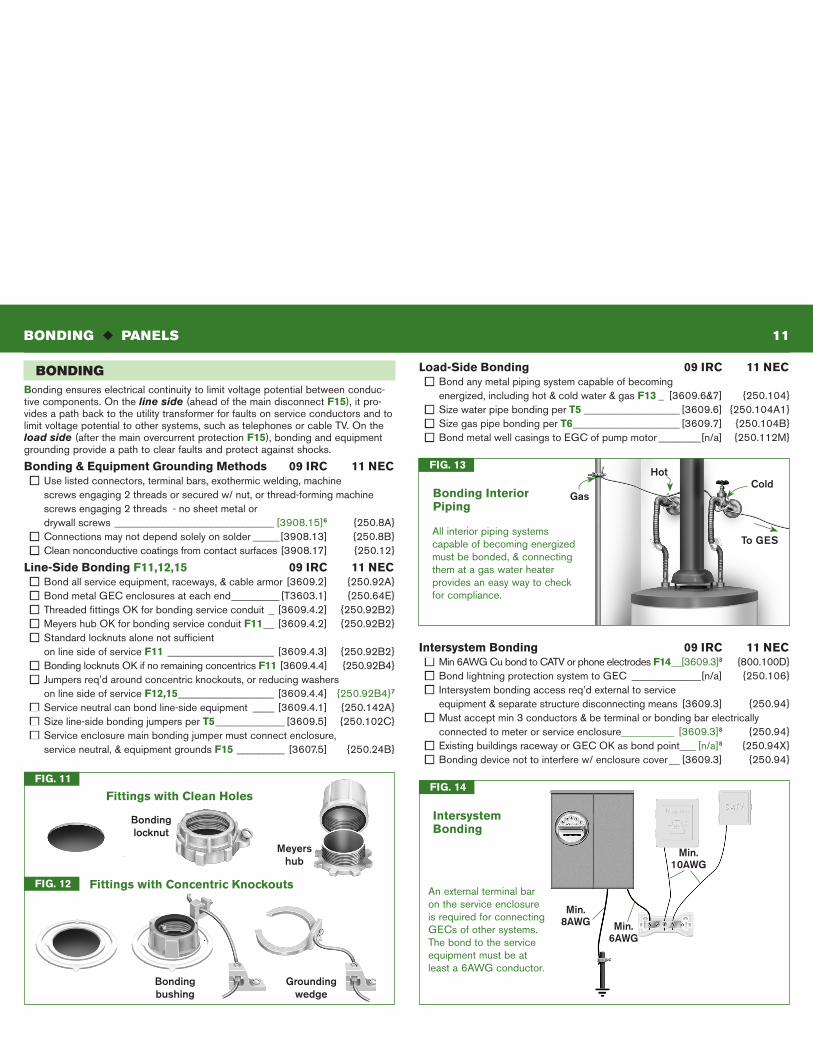
Intersystem Bonding 09 IRC 11 neCn Min6AWGCubondtoCATVorphoneelectrodesF14 __[3609.3]8 {800.100D}n Bond lightning protection system to GEC _____________[n/a] {250.106}n Intersystem bonding access req’d external to service equipment & separate structure disconnecting means [3609.3] {250.94}n Must accept min 3 conductors & be terminal or bonding bar electrically connected to meter or service enclosure__________ [3609.3]8 {250.94}n ExistingbuildingsracewayorGECOKasbondpoint ___ [n/a]8 {250.94X}n Bonding device not to interfere w/ enclosure cover __ [3609.3] {250.94}
FIG. 14
Intersystem Bonding
Min.8AWG
An external terminal bar on the service enclosure is required for connecting GECs of other systems. The bond to the service equipment must be at least a 6AWG conductor.
Min.10AWG
Min.6AWG
Groundingwedge
Meyers hub
FIG. 11
Fittings with Clean Holes
FIG. 12 Fittings with Concentric Knockouts
Bonding locknut
Grounding wedge
Bonding bushing
Gas
FIG. 13
Bonding Interior Piping
HotCold
All interior piping systems capable of becoming energized must be bonded, & connecting them at a gas water heater provides an easy way to check for compliance.
To GES
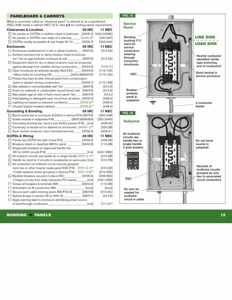
pANELBOARD & CABINETS what is commonly called an “electrical panel” is referred to as a panelboard (NEC 408) inside a cabinet (NEC 312). See p.5 for working space requirements.
Clearances & Location 09 IRC 11 neCn No panels or OCPDs in clothes closet or bathroom _ [3405.4] {240.24D&E}n No panels or OCPDs over steps of a stairway _____ [3405.4]9 {240.24F}n OCPDs readily accessible & max height 6ft 7in _____ [3705.7] {240.24A}
enclosures 09 IRC 11 neCn Enclosures weatherproof in wet or damp locations __ [3907.2] {312.2A}n Surface-mounted wet or damp location metal enclosures min 1/4in air gap between enclosure & wall _________ [3907.2] {312.2A}n Equipment rated for dry or damp locations must be protected against damage from weather during construction ___ [3404.4] {110.11}n Open knockouts & twistouts durably filled EXC _____ [3404.5] {110.12A} •ManuholesformountingOK ____________[3404.6&3907.5] {110.12A}n Protect bus bars & other internal parts from contamination (paint or plaster) during construction ______________ [3404.7] {110.12B}n Max setback in noncombustible wall 1/4in _____________[3907.3] {312.3}n Flush (no setback) in combustible (wood-frame) wall [3907.3] {312.3}n Max plaster gap at side of flush mount panel 1/8in ___ [3907.4] {312.4n Field labeling to distinguish each circuit from all others _[3706.2] {408.4}n Labeling not based on transient conditions ________ [3706.2]10 {408.4}
n Unused (spare) breakers labeled ________________ [3706.2]11 {408.4}
Grounding & Bonding 09 IRC 11 neCn Bond neutral bar to enclosure & EGCs in service F15 [3607.5] {250.24B}n Isolate neutrals in subpanels F16 ___________ [3607.2&3908.6] {250.24A5}n Grounding terminal bar req’d if wire EGCs present F16 __[n/a] {408.40}n Continuity of neutral not to depend on enclosures [3406.11]12 {200.2B}n Each neutral conductor req’s individual terminal _____ [3706.4] {408.41}
oCPds & wiring 09 IRC 11 neCn Panels req OCPD line side of bus F15 ____________ [3706.3] {408.36}n Breakers listed or classified AMI for panel _________ [3403.3] {110.3B}n Single-pole breakers w/ approved handle ties OKfor240VcircuitsF16 ___________________________[n/a] {240.15B2}n All multiwire circuits req handle tie or single handle [3701.5.1]13 {210.4B}n Handle tie req’d for 2 circuits to receptacles on same yoke [n/a] {210.7B}n All conductors of multiwire circuit must be grouped (wire ties or other means) inside panel EXC F16 _ [3701.5.1]14 {210.4D} •CablesystemswheregroupingisobviousF16 _ [3701.5.2]14 {210.4DX} n Backfed breakers secured in place EXC ___________ [3706.5] {408.36D} •OutputcircuitsfromutilityinteractivePVinverter _______[n/a] {705.12D6}n Torque all breakers & terminals AMI _______________ [3403.3] {110.3B}n Antioxidant on Al conductors AMI __________________ [local] {local}n Secure each cable entering panel AMI F15,16 _____ [3907.8] {312.5C}n Splices&tapsinpanelsOKto40%fill ____________ [3907.1] {312.8}n Apply warning label to enclosure identifying power source of feed-through conductors __________________________[n/a] {312.8}15
FIG. 15
ServicePanel
FIG. 16
Subpanel
Bond neutral in service enclosure
Do not bond neutral in subpanel.
Neutrals of multiwire circuits grouped by wire ties to associated circuit conductors
No wire tie needed for multiwire circuit in cable.
All multiwire circuits req. handle ties or single-handle 2-pole breaker.
4-conductor feeder
Neutral conductor identified (white tape encircling end of conductor)
Bonding bushing F12 req’d for service conductors entering through concentric knockouts.
Breaker protects panel & subpanel
GEC
LINE SIDE
LOAD SIDE
EGC
BONDING u pANELS 12