COCKSHUTT...Be sure the gear shift lever is in neutral before startingthe engine. 2. Always engage...
40
January 18, 1947 Limited COCKSHUTT "30" TRACTOR Standard and Row Crop M AR 3 1 94 7 COCKSHUTT PLOW COMPANY LIMITED TRURO • MONTREAL BRA NT FOR D WINNIPEG· REGINA • SASKATOON SMITHS FALLS CAN ADA CALGARY • EDMONTON 2,780-2·47-H. I'rinteJ in Canada https://tractormanualz.com/
Transcript of COCKSHUTT...Be sure the gear shift lever is in neutral before startingthe engine. 2. Always engage...
January 18, 1947
~Y, Limited
COCKSHUTT "30" TRACTORStandard and Row Crop
-U-N'~V£~RS~IT;:V-Y ~ofmNE~BRnAA~SKmA
©~©l~liW~'trJ~ MAR 3 1947 ~
COCKSHUTTPLOW COMPANY LIMITED
TRURO • MONTREAL BRA N TFOR D WINNIPEG· REGINA • SASKATOON
SMITHS FALLS CAN A D A CALGARY • EDMONTON
2,780-2·47-H. I'rinteJ in Canada
https://tractormanualz.com/
2 Operating Instructions for Cockshutt "30" Tractor
FOREWORDYour tractor has become your partner and will amply return the investment you haveplaced in it . Years of thought and experience and close contact with farmers have resulted in the many refinements and features built into the tractor. It has been carefullymanufactured under close supervision and careful inspection and if it is given the careand service outlined in this manual, years of trouble-free operation will result.
BEFORE OPERATING YOUR NEW TRACTORSTUDY THIS MANUAL CAREFULLY
If you feel that you require information not contained in this manual consult your dealer who has the trained personnel and the required equipment to give you the service yourequire. All dealers are kept informed on the best methods of handling your tractor problems and their mechanics have the training and experience on your tractor to give yourproblems personal attention and quick satisfaction.Dealers carry ample stocks of genuine parts and in turn are backed by the full facilitiesof the Company with Branches and Distributors conveniently located. When parts are required be sure to give the dealer your engine and tractor serial numbers. It is suggestedthat you write these in the space provided below.
Tractor Serial Number .
Engine Serial Number ..
It is the policy of the Company to make continuous improvements in their products, andthe Company has the right to make these changes at any time without incurring obligation to add them to any tractor already sold.
https://tractormanualz.com/
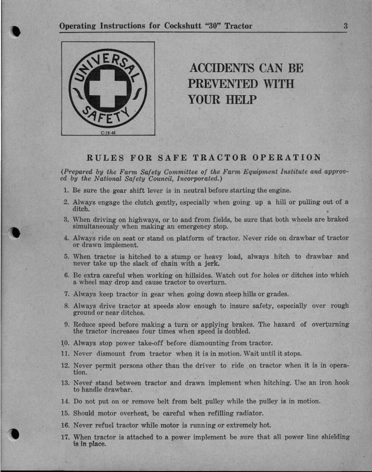
(Prepared by the Farm Safety Committee of the Farm Equipment Institute and approved by the National Safety Council, Incorporated.)
1. Be sure the gear shift lever is in neutral before starting the engine.
2. Always engage the clutch gently, especially when going up a hill or pulling out of aditch.
3. When driving on highways, or to and from fields, be sure that both wheels are brakedsimultaneously when making an emergency stop.
4. Always ride on seat or stand on platform of tractor. Never ride on drawbar of tractoror drawn implement.
5. When tractor is hitched to a stump or heavy load, always hitch to drawbar andnever take up the slack of chain with a jerk.
6. Be extra careful when working on hillsides. Watch out for holes or ditches into whicha wheel may drop and cause tractor to overturn.
7. Always keep tractor in gear when going down steep hills or grades.
8. Always drive tractor at speeds slow enough to insure safety, especially over roughground or near ditches.
9. Reduce speed before making a turn or applying brakes. The hazard of overturningthe tractor increases four times when speed is doubled.
10. Always stop power take-off before dismounting from tractor.
11. Never dismount from tractor when it is in motion. Wait until it stops.
12. Never permit persons other than the dri vel' to ride on tractor when it is in opera-tion. . .
13. Never stand between tractor and drawn implement when hitching. Use an iron hookto handle drawbar.
14. Do not put on or remove belt from belt pulley while the pulley is in motion.
15. Should motor overheat, be careful when refilling radiator.
16. Never refuel tractor while motor is running or extremely hot.
17. When tractor is attached to a power implement be sure that all power line shieldingis in place.
Operating Instructions for Cockshutt "30" Tractor
ACCIDENTS CAN BEPREVENTED WITHYOUR HELP
C·18 ·46
RULES FOR SAFE TRACTOR OPERATION
3
https://tractormanualz.com/
4 Operating Instructions for Cockshutt "30" Tractor
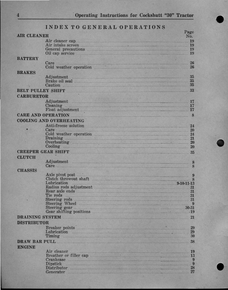
IN DE X TO G ENE RA L 'O PE RAT I ON SPageNo.
. 19
. 19.. ........ ..... 19
............. .............. 19
AIR CLEANERAir cleaner cap .Air intake screen .General precautions .Oil cap service .
BATTERY
BRAKES
Care .Cold weather operation ..
. 26.. 26
Adjustment 35Brake oil seal 35Caution 35
BELT PULLEY SHIFT .. . .. 33CARBURETOR
Adjustment 17Cleaning . .. 17Float adjustment . 17
CARE AND OPERATION 8COOLING AND OVERHEATING
Anti-freeze solution 24• Care _ 20
Col~ weather operation 24Drammg . 21Overheating 20Cooling 20
CREEPER GEAR SHIFT . 35CLUTCH
Adjustment 8Care 8
CHASSISAxle pivot post .....:............................................................................................ ...... 9Clutch throwout shaft 8Lubrication 9-10-11-13Radius rods adjustment 31Rear axle ends .. 31Tie rods 31Steering rods 31Steering Wheel 9Steering gear . . 30-31Gear shifting positions . . ..... ................ . 19
DRAINING SYSTEM . 21DISTRIBUTOR
Breaker points ~ 29Lubrication 29Timing 30
DRAW BAR PULL .. 38ENGINE
Air cleaner 19Breather or filler cap : 13Crankcase 9Dipstick 9Distributor 28Generator 27
https://tractormanualz.com/

HITCH
FAN BELT
SAFETY RULES : 3
STARTING INSTRUCTIONS 8
5
Adjustment 38
IGNITION SWITCH 14
INSTRUMENT PANEL AND CONTROLS 14-15
LIGHT SWITCHHow to adjust for proper charge 26
LUBRICATION 9-10-11-12-13
OIL FILTERHow to change oil 18How to replace elements 18Kind of elements :": .. 18
PageNo.
Oil filter 18Oiling system 12Oil pressure 12Quality of oil 12When to add oil ~ .. .. .. .. . . . . . .. .. . . . .. . .. . . . .. . . . . .. . . .. .. .. .. . .. .. . . . . . 9Quantity of oil : 12Type of oil 12When to change oil 12
Care of belt 20Tension :................................................................... 20
FRONT WHEELSAlignment 31Adjustment 31Bearing adjustment 31Lubrication 13Quality of grease 9Quantity of grease ,..................................... 13When to change grease 13
GENERATORCare 27Adjustment 27
Operating Instructions for Cockshutt "30" Tractor
PULLEY HOUSINGCare of belt pulley 33Oil filler plug 33Oil drain plug 33Pulley shift 33Quality of oil 12
REAR TREADAdjustment 36Example 37
STARTERCare 26
https://tractormanualz.com/
6 Operating Instructions for Cockshutt "30" Tractor
PageNo.
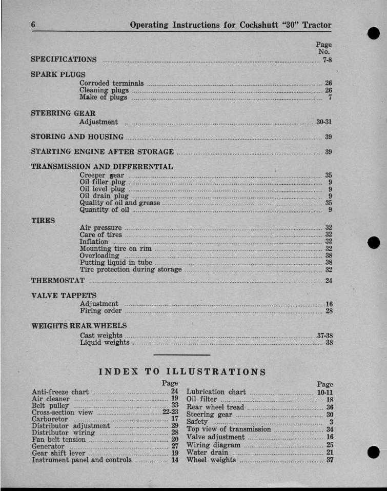
SPECIFICATIONS : 7·8
SPARK PLUGSCorroded terminals 26Cleaning plugs 26Make of plugs 7
STEERING GEARAdjustment 30-31
STORING AND HOUSING 39
STARTING ENGINE AFTER STORAGE 39
TRANSMISSION AND DIFFERENTIALCreeper gear :..... ........ ....... ....... 35Oil filler plug 9Oil level plug 9Oil drain plug 9Quality of oil and grease 35Quantity of oil 9
T~RESAir pressure 32Care of tires _.... ................ .... ....... ....... 32Inflation 32Mounting tire on rim 32Overloading _ 38Putting liquid in tube 38Tire protection during storage 32
THERMOSTAT : 24
VALVE TAPPETSAdjustment : 16Firing order 28
WEIGHTS REAR WHEELSCast weights : 37·38Liquid weights 38
INDEX ' T O ILLUSTRATIONSPage
Anti-freeze chart 24Air cleaner 19Belt pulley 33Cross-section view 22-23Carburetor 17Distributor adjustment 29Distributor wiring 28Fan belt tension 20Generator 27Gear shift lever 19Instrument panel and controls 14:
PageLubrication chart 10·11Oil filter 18Rear wheel tread 36Steering gear 30Safety .......................................................... 3Top view of transmission 34Valve adjustment 16Wiring diagram 25Water drain 21Wheel weights 37
https://tractormanualz.com/
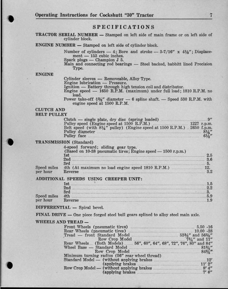
ENGINECylinder sleeves - Removeable, Alloy Type.Engine lubrication - Pressure.Ignition - Battery through high tension coil and distributor.Engine speed - 1650 R.P.M. (maximum) under full load; 1810.R.P.M. no
load.Power take-off ·1% " diameter - 6 spline shaft. - Speed 530 R.P.M. with
engine speed at 1500 R.P.M.
TRACTOR SERIAL NUMBER - Stamped on left side of main frame or on left side ofcylinder block.
ENGINE NUMBER - Stamped on left side of cylinder block.
Number of cylinders - 4; Bore and stroke - 3-7/16" x 4th"; Displacement - 153 cubic inches.
Spark plugs - Champion J 5.Main and connecting rod bearings - Steel backed, babbitt lined Precision
Type.
7
SPECIFICATIONS
CLUTCH ANDBELT PULLEY
Clutch - single plate, dry disc (spring loaded) 9"Pulley speed (Engine speed at 1500 R.P.M.) 1227 r.p.m,Belt speed (with 8%," pulley) (Engine speed at 1500 R.P.M.) .. 2650 f.p.m,Pulley diameter 8%,"Pulley face 6%"
TRANSMISSION (Standard)4-speed forward; sliding gear type.(Based on 10-38 pneumatic tires; Engine speed -1500 r.p.m.)1st 2.52nd 3.63rd ~ 5.
Speed miles 4th (At maximum no load engine speed 1810 R.P.M.) 12.per hour Reverse .................................................... 3.2
ADDITIONAL SPEEDS USING CREEPER UNIT:1st 1.52nd 2.23rd 3.
Speed miles 4th 5.9per hour Reverse 1.9
DIFFERENTIAL - Spiral bevel.
FINAL DRIVE - One piece forged steel bull gears splined to alloy steel main axle.
WHEELS AND TREAD -Front Wheels (pneumatic tires) 5.50 -16Rear Wheels (pneumatic tires) 10.00 -38.Tread - front Standard Model 53%" and 560/8"
Row Crop Model 73,4" and 11"Rear Wheels ... (Both Models) 56", 60", 64", 68", 72", 76", 80" and 84"Wheel Base - Standard Model 81%,"
Row Crop Model 84%.'~
Minimum turning radius (56" rear wheel thread)Standard Model- (without applying brakes 12'
. (applying brakes 11' 2"Row Crop Model - (without applying brakes 8' 4"
(applying brakes 7' (\"
Operating Instructions for Cockshutt "30" Tractor
https://tractormanualz.com/
8 Operating .Instructions for Cockshutt "30" Tractor
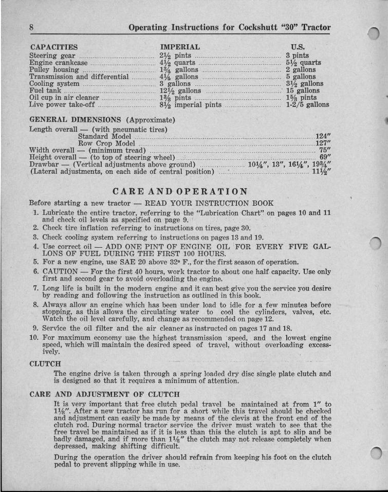
CAPACITIES IMPERIALSteering gear 2% pints ..Engine crankcase 4% quarts .Pulley housing 1%. gallons .Transmission and differential 4tA, gallons .Cooling system 3 gallons ..Fuel tank 12% gallons : .Oil cup in air cleaner 1% pints .Live power take-off 8% imperial pints .
u s,3 pints5% quarts2 gallons5 gallons3% gallons15 gallons10/8 pints1-2/5 gallons
GENERAL DIMENSIONS (Approximate)Length overall - (with pneumatic tires)
. Standard Model ~ 124"Row Crop Model 127"
Width overall - (minimum tread) 75"Height overall - (to top of steering wheel) :: 69"Drawbar - (Vertical adjustments above ground) 10tA,", 13", 16%,", 193,4"(Lateral adjustments, on each side of central position) ~ ; 11%"
CARE AND OPERATIO NBefore starting a new tractor - READ YOUR INSTRUCTION BOOK
1. Lubricate the entire tractor, referring to the "Lubrication 'Chart" on pages 10 and 11and check oil levels as specified on page 9. ' .
2. Check tire inflation referring to instructions on ti res, page 30.3. Check cooling system referring to instructions on pages 13 and 19.4. Use correct oil - ADD ONE PINT OF ENGINE OIL FOR EVERY FIVE GAL
LONS OF FUEL DURING THE FIRST 100 HOURS.5. For a new engine, use SAE 20 above 320 F ., for the first season of operation.6. CAUTION - For the first 40 hours, work tractor to about one half. capacity. Use only
first and second gear to avoid overloading the engine.7. Long life is built in the modern engine and it can'best g-ive you the service you desire
by reading and following the instruction as outlined in this book.8. Always allow an eng-ine which has been under load to idle for a few minutes before
stopping, as this allows the circulating water to cool the cylinders, valves, etc.Watch the oil level carefully, and change as recommended on page 12.
9. Service the oil filter and the air cleaner as instructed on pages 17 and 18.10. For maximum economy use the highest transmission r speed, and the lowest engine
speed, which will maintain the desired speed of travel, without overloading excessively.
CLUTCHThe engine drive is taken through a spring loaded dry disc single plate clutch andis designed so that it requires a minimum of attention.
CARE AND ADJUSTMENT OF CLUTCHIt is very important that free clutch pedal travel .be maintained at from 1" to1%". After a new tractor has run for a short while this travel should be checkedand adjustment can easily be made by means of the clevis at the front end of theclutch rod . During- normal tractor service the driver must watch to see that thefree travel be maintained as if it is less than this the clutch is apt to slip and bebadly damaged, and if more than l1;~" the clutch may not release completely whendepressed, making shifting difficult. .
During the operation the driver should refrain from keeping his .foot on the clutchpedal to prevent slipping while in use.
https://tractormanualz.com/

[!] EVERY 120 HOURS OF OPERATION. S Replace oil filter element as per instructions17. Oil Filter Element ~ given on page 19.
KEY TO LUBRICATION CHARTNOTE: The symbols shown by the reference numbers on the illustrations indi
cate the intervals of lubrication.Specifications of lubricants referred to are given on pages 12 and 13.
9
Use standard Alemite grease and put2 or 3 shots from the grease gun intoeach Alemite fitting. .
Drain all oil from crankcase pan. Refill with newoil to full mark on dipstick. Capacity - 4V2Imperial quarts. Refer to specifications of lubricant page 12, Type of Oil.
Few drops of engine oil in oil cup.
Few drops of engine oil in oil cups.
Clean and refill oil cup to oil level bead with samenew oil as used in the engine crankcase. Capacityl?;1g Imperial pints. Refer to page 18 foradditional information.
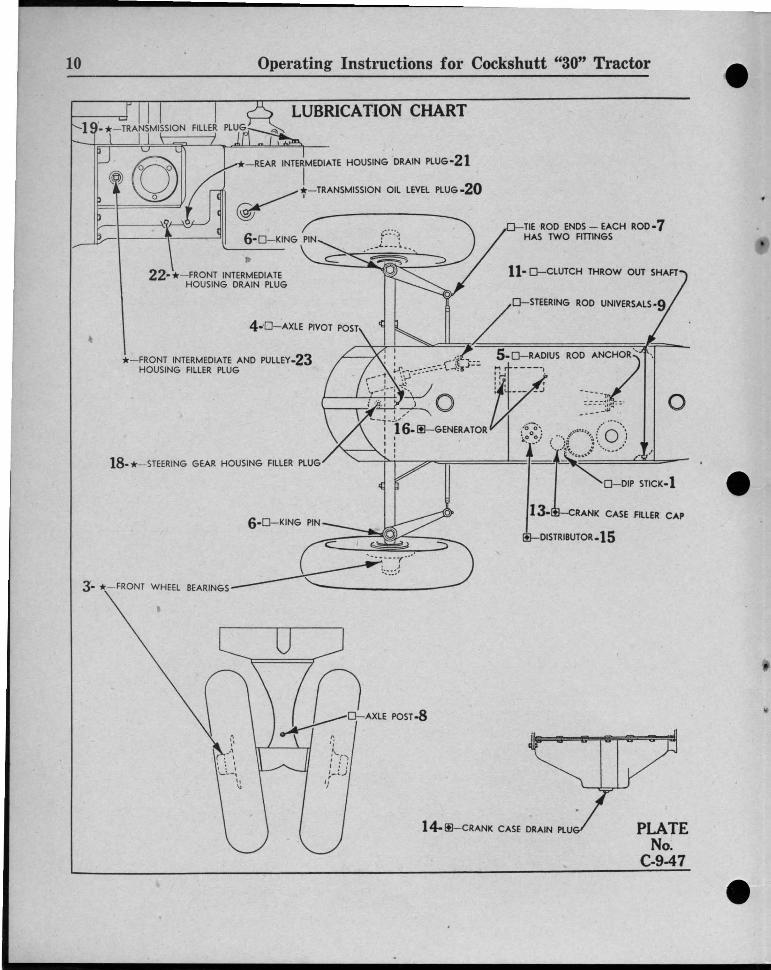
LUBRICATION CHARTPLATES No. C-9-46 and D-9-46, Pages 10 and 11
* PERIODICALLY - Check at test plug once a month, replace lubricant every 1000hours of use.
18. Steering Gear Housing - Filler plug on top cover. Use SAE 140. Capacity 2% Imper-ial pints. .
3. Front Wheel Bearings.
TRANSMISSION AND DIFFERENTIALUse approved lubricant SAE 90. Check lubricantonce a month and bring level up to level plug(20). Refer to page 33 for further instructions.Capacity - 4~ Imperial gallons.
19. Oil Filler Plug J20. Oil Level Plug l21. Oil Drain Plugs (2) ..
~ WEEKLY OR EVERY 60 HOURS OF OPERATION
{Wash in gasoline, dip in engine oil, shake off ex-
13. Filler Cap cess. Clean oftener if dust is present.
14. Crankcase Pan Oil Drain Plug .. 1
15. Distributor ..
16. Generator .
4. Axle Pivot Post, Standard Model only - 15. Radius Rod Anchor, Standard Model' - 16. Axle King Pins, Standard Model only - 27. Tie Rod Ends, Standard Model only - 48. Axle Pivot Post, Row Crop Model only - 19. Steering Rod Universals - 2
10. Steering Wheel Shaft Support - 111. Clutch Throw-out Shaft - 212. Rear Axle Ends - 2
o DAILY OR EVERY 10 HOURS OF OPERATION
~If oil level is at, or below, the low mark on the
1. Dipstick dipstick, add new oil until oil level is up to thefull mark.
2. Air Cleaner 1
Operating Instructions for Cockshutt "30" Tractor
https://tractormanualz.com/
10 Operating Instructions for Cockshutt "30" Tractor
LUBRICATION CHART
oROD.·~7HOR"
"1==----.~ : f;: .:. .
_.'"- _.... .
TIE ROD ENDS - EACH ROD-7HAS TWO FITIINGS
11- D-CLUTCH THROW OUT SHAFT
S-D-RADIUS.., t- ---'0:~ -I I, r: _ ...__ .J
0 " • • .. ~ ..
' 0 0 ' . .1 0 ' ",' 111,, " O ''.? .~/ ( ....~{ ) \....•• •)
'---r'i---:::<~::;:;====:!:==r cf~~=D-=DI~P~ST~:~bK"'_I-
13-LRANK CASE FILLER CAP
DISTRIBUTOR-IS
- REAR INTERMEDIATE HOUSING DRAIN PLUG-21
I~~-TRANSMISSION OIL LEVEL PLUG-20
~ ~.D-"NG "N .••C~:t_." _22-*-FRONT INTERMEDIATE
HOUSING DRAIN PLUG
* -FRONT INTERMEDIATE AND PULLEY-23HOUSING FILLER PLUG
18. * - STEERING GEAR HOUSING FILLER PLUG
6-D-KING PIN
__----'={!~'J----_c.. I ~
3 '- * -FRONT WHEEL BEARINGS~,~"~:r' "
I
•
14-IE-CRANK CASE DRAIN PLUG PLATENo.
C-9-47
https://tractormanualz.com/

11
PLATENo.
D-9-47
17-lID-OIL f'ILTER-- ~
f / D-REAR AXLE END BEARING-12
r,.,r:
-Y-'EA>. AXLE END 'EA>.'"0-12
II
LUBRICATION CHART
2-D-AIR CLEANER
[§}-ATI'END TO EVERY 120 HOURS
KEY__ D-ATTTEND TO DAILY OR EVERY 10 HOURS
Itl-ATI'END TO WEEKLY OR EVERY 60 HOURS
*-ATI'END TO PERIODICALLY
STEERING SHAFT SUPPOIRT -10
* -PULLEY HOUSING DRAIN PLUG -24
I \
STEERING ROD UNIVERSALS-9
) \ .
.Y:--r=r-r===~~'I==I)~==l __-r-r~_ _~.;, *-TRANSM'''ON ORA'" PLUG-21~
Operating Instructions for Cockshutt "30" Tractor
https://tractormanualz.com/

12 Operating Instructions 'for Cockshutt "30" Tractor
FRONT INTERMEDIATE AND PULLEY HOUSING
Use a few drops of engine oil occasionally on thelinkages or .control rod .connections such as clutchrod, brake linkages, throttle linkages, etc.
22. Front Intermediate HousingDrain Plug .
23. Oil Filler Plug .24. Oil Drain Plug .
LIVE P OWER TAKE-OFF (Ext r a )
25. Oil Filler Plug .26. Oil Drain Plug .
MISCELLANEOUS PARTS
IUse approved lubricant SAE 90. Check lubricantlevel once a month and bring level up to oil fillerplug (22). Capacity - 1%, Imperial gallons.
1Use approved lubricant SAE 90. Check level oncea month whether in use or not. Change oil every1000 hours of power take-off use. Capacity 8%Imperial pints.
~
ENGINE LUBRICATIONENGINE OILING SYSTEM - Functioning as it does to provide lubrication for all the
moving parts of the engine which operates under different conditions of. heat andpressure, it is necessary that a good grade of engine oil. be used. It is also important that the oil be kept CLEAN and in a CLOSED CLEAN CONTAINER "
. . • . i
DESCRIP TION - Pressure is furnished by a gear type pump whi ch draws the oil fromthe crankcase through a screen. From the pump it goes through passages drilled inthe block to the main and connecting rod bearings. The connecting rods are rifledrilled for satisfactory wrist pin lubrication. Oil is metered to th e rocker arm shaftfor satisfactory rocker arm lubrication and to the rock er arm valve contact faces.The camshaft is oiled by splash and by oil draining from the head through coredpassages in the block. The governor, governor shaft, and timiriggears are liberally bathed in oil to prevent undue wear and to wash off accumulated sludge andmoisture. Part of the oil is by-passed through the filter. (See page 17 for servicing.
PRESSURE CONTROL - A pressure reli ef valve is located at the front of the oilgall ery on the left side of the block and should not require attention. It is dangerous to tighten up a pressure valv e to correct a drop in pressure, as normally such adrop is caused by some ' bearing being worn. The oil pressure as indicated on·t hegauge should be from 20 to 25 pounds at full throttle and 8 to 10 pounds at idlespeed. ; '
TYPE OF OIL - Above 320 F ., SAE 30 should be used, from - 100 F. to 320 F. use SAE20W, and below 100 F., use SAE lOW. Always use top quality oil..
CAUTION: For a new engine use SAE 20 above 320 F. for the first season of operation.
WHEN TO CHANGE AND ADD OIL - It is a good practice to change the oil every 60hours and if running in cold weather the change should he made more often. Theoil capacity is 4% Imperial quarts. Always look at the oil pressure gauge immediatelv after starting the engine. The oil level should be checked at least once a dayand if at, or below, the low mark on the dipstick, some should be added.
QUALITY OF OIL - The best insurance of good qualitv is to buy from a reputablemanufacturer. Oils should be free from foreign substances such as scans. r esins,acids, etc., and shou ld not corrode the engine surfaces. The newer, so-called heavvduty oils are satisfactory hut if an engine has heen run on oth er tvpes of oils donot add heavy-duty oil without thoroughlv flushing ' the crankcase by ari approvedmotor fl ush svstem. Even after this is done. t.he new heavy-duty oil should bechanged at 10 hours, then at 25, and then at 60.
https://tractormanualz.com/
CHASSIS LUBRICATION
FRO NT WHEEL BEARINGS - To provide satisfactory lubrication to the front wheelbearings remove wheels, clean and repack with wheel bearing grease periodically.
QUALITY OF LUBRI CANT - Use a good grade of mineral oil made by a reputablemanufacturer as the best assurance of trouble-free service. SAE 90 transmissionlubr icant can be used both winter and summer.
13Operating Instructions for Cockshutt "30" Tractor
BREATHER CAP - This cap acts as a filter to clean the air which surges into and outof an engine when it is operating. To remove dust and dirt from the air drawn inon the inward surge, the screen must be kept clean and covered with oil. It shouldbe inspected and if dirt is present, the cap should be washed in gasoline, then dipped in engine oil, excess oil shaken off, and the cap put in place again.
PRESSURE GUN LUBRICATION - Use a good quality grease, not one that will thinout under load and moderate temperatures. Keep the grease and the gun clean clean each fitting before use and force enough lubricant into fitting to insure afresh supply to the wearing surfaces.
At least once a year, or every 1000 hours, drain transmission compartments by removingthe three plugs, 21 and 22, on the lubrication chart. Preferably the draining should bedone whi le the tractor is warm.
The transmission will require 4%, Imperial gallons (5 U.S. gallons) to fill and the pulleyhous ing I %, Imperial gallons (2 U.S. gallons). After filling the transmission do not usethe creeper with the shift in the low speed (lever towards the rear) until the tractor hasbeen operated for about one hour or so, asthis chamber is filled from the transmission bysplash.
If th e tractor is operated at very low temperature the pulley housing and transmissionlubri cant may be thinned with one half gallon of kerosene, but before using in warm weather th is thinned mixture MUST be drained and replaced by new oil.
https://tractormanualz.com/

14 Operating Instructions for Cockshutt "30" Tractor • •INSTRUMENT PANELAND CONTROLS
)} ) /:J 7 / ~I
PLATENo.~47
• •INSTRUMENT PANEL AND CONTROLS
P LAT E No. C·8-46
CHOKE LEVER - as indicated by arrow (1)This control near the upper right cover of th e instrument panel is held in the openposition by spring pressure and shoul d be used only when starting. Th e spri ng loaded feature prevents undue choking and unn ecessa ry engine wear an d excessive fuelconsumption.
IGNITION SWITCH - as indicated by arrow (2)Duplicate keys are provided and should be removed to prevent loss, theft or tampering with th e tractor by unauthoriz ed persons. Tu rn to right when ready to startthe engine - to the left or upright position when it is desired to stop the engine.
LIGHT SWITCH and GEN ERATOR CONT ROL SWITCH - as indicated by arrow (3)This is combined into one and has three positions: (a ) full in-low rate charge;(b) half out-high rate charge; (c) full out-lights on and generator full cha rge.(See further instructions under Wiring Diagam on page 22.
STARTER SWITCH - as indicated by arrow (4)This is pushed when one desires to start the eng ine. CAUTION - ALWAYS havegear shift in neutral posit ion when starting. • •
https://tractormanualz.com/

OIL GAUGE - as indicated by arrow (5)This shows the pressure in the oil lin es leading from the pump to the engine bearings and should be watched every time the engine is started. Pressure should bebetween 20 to 25 pounds. If not between these pressures check th e oil level, and ifbelow the "low" mark, check for leaks in th e oil lines to th e filter and gauge. Ifth ere are none, a qualified mechanic should be consulted and the engine should notbe run until corrected.
AMMETER - as indicated by arrow (6)With the light switch half out (first notch past full- in) th e amm eter should showfrom 10 to 15 amperes charge.
INSTRUMENT PANEL LI GHT - as indicated by ar row (7)The switch on the panel light will turn the light on only when the igni t ion switchis turned to allow operation without the headlights being on and also to preventbeing left on when the tractor is not in operat ion.
BRAKE PEDALS AND INTERLOCKING P IN - as indicated by arrow (8)
The brake pedals should be used to stop th e tractor, hold th e tractor in a stationary position, and to assist in mak ing shar p turns as outlined below :
(1) To stop th e tractor, the pedals should be locked together so both brakes willoperate simultaneously.
(2) To hold the tractor in a station ary position, lock the pedals together, depressand lock th em in the depressed posit ion using th e brake pedal lock.
(3) To assist in making a sharp tur n, the pedals must be operated individually,depressing the pedal on the side toward which the turn is to be made.
CAUTION - Always lock pedals together by means of th e sliding pin, when travelling on th e road in fourth speed.
BRAKE PEDAL LOCK - as indicated by arrow (9)This is shoved down while one's foot is being removed from th e brake pedals tolock th e pedals down and thus prevent th e tractor from moving.
ENGINE SPEED CONT ROL LE VER - as indicated by arrow (10)Through th e governor this lever, when adjusted to the desired speed, keeps th eengin e speed uniform under varying load conditions.
CLUTCH PEDAL - as indicated by arrow (11)When depressed all the way this pedal disengages th e t ransmission from th eengine. CAUTION - Do NOT operate tractor with foot resting on clutch pedal.
HEAT INDICATOR - As indicated by arrow (12) . This instrument indicates th e tempera tu re of the liquid in th e cooling system.
CAUTION - Do not operate the tractor wi th the cooling liqu id boiling. Operation of thetractor at this temperature will result in -damage to the engine.
GEAR SHI FT LEVER - As indicated by ar row (13) . Th is is of an automotive type.
•
•
Operating Instructions for Cockshutt "30" Tractor 15
https://tractormanualz.com/
ENGINECONSTR UCTION - The engine is a heavy duty, 4 cylinder, valve in head, wet sleeve
motor with a pressure oiling system as described in detail on page 12.A water pump is used with a full flow by-pass thermostat to insure constantmotor temperature which is so important in securing long life from the wearingparts. All working parts are protected by the large capacity oil filter used, theheavy duty air cleaner, and the careful sealing of the main bearings at the frontand rear of the crankshaft.
The high quality variable speed governor provides constant engine speed control.The main connecting rod bearings are of high precision, interchangeable, stee lbacked babbit design.
SERVIC E - It is strongly recommended that, should any work have to be done on themotor, it be taken to your dealer. You I' dealer has the proper facilities and thetrained personnel to give your tractor the eff icient attention that it deserves.
16 Operating Instructions for Cockshutt "30" Tractor ••
•
VALVE ADruSTMENT
3
[J~~i?£PP;LATENo.
C·21-46
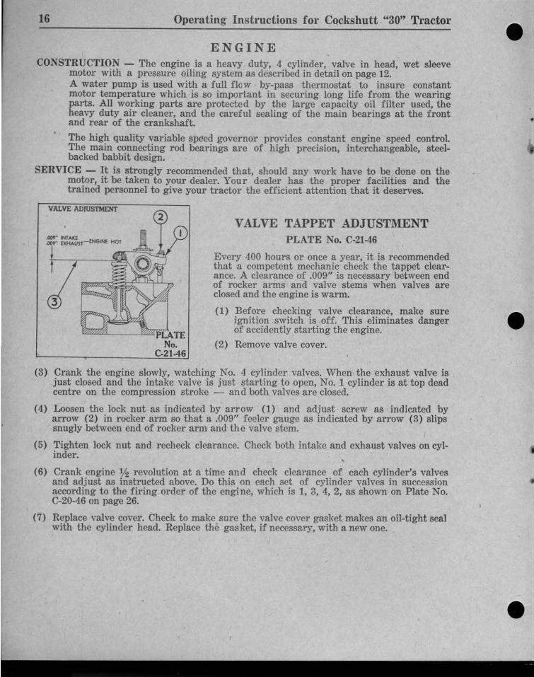
VALVE TAPPET ADJUSTMENTPLATE No. C-21-t6
Every 400 hours or once a year, it is recommendedthat a competent mechanic check the tappet clearance. A clearance of .009" is necessary between endof rocker arms and valve stems when valves areclosed and th e engine is warm.
(1) Before checking valve clearance, make sureignition switch is off. This eliminates dangerof accidently starting the engine.
(2) Remove valve cover. • •(3) Crank the engine slowly, watching No.4 cylinder valves . When the exha ust valve is
just closed and the intake valve is just starting to open, No.1 cylinder is at top deadcentre on the compression stroke - and both valves are closed.
(4) Loosen the lock nut as indicated by arrow (1) and adjust screw as indicated byarrow (2) in rocker arm so that a .009" feeler gauge as indicated by arrow (3) slipssnugly between end of rocker arm and the valve stem.
(5) Tighten lock nut and recheck clearance. Check both intake and exhaust valves on cylinder. ,
(6) Crank engine 1f2 revolution at a time and check clearance of each cylinder's valvesand adjust as instructed above. Do this on each set of cylinder valves in successionaccording to the firing order of the engine, which is 1, 3, 4, 2, as shown on Plate No.C-20-46 on page 26.
(7) Replace valve cover. Check to make sure the valve cover gasket makes an oil-tight sealwith the cylinder head . Replace the gasket, if necessary, with a new one.
• •https://tractormanualz.com/

17
CA RBU R E T O RPLATE No. C-17-46
Fu nctioning as it does to provide anefficient f uel mixture over wide rangesof load and speed. and having to takein fuel which may have impuriti es init. it is only reason able that a littleattention should be paid to the carburetor .
PLATENo.
C.I746
•
CARBURETOR
(1) ADJUSTMENT-High Speed J etas indicated by arrow (1). Thisadjustment is provided to takecare of different fuels and operating conditions and while anew engine requires a slightlyri cher mixture. the operatorwill soon find that the tractorperforms best with the screwfrom 1 to 1% turns open. Thisadjustment can best be performed with th e tractor at nor-
mal working temperature and under load. and after a few trials th e correct position will be found . Nothing is to be gained by operating with too lean a mixtureas power is lost and th e engine will run warmer.
If the carburetor is thought to be dirty remove the carburetor. dissemble it by removing th e four screws holding the body ha lves together and wash carefully ingasoline. If it is necessary to remove the jets do so very carefully, as even theslightest damage to th e jets will throw out th e calibration of the carburetor .These jets should be blown out with air. DO NOT use a wire. Reassemble carefully,being sure that all gaskets arc in place, screws tight and the air tube to th e cleaner carefully installed and checked for air leaks.
(3 )
Operating Instructions for Cockshut t "30" Tractor
Idle Adj ustment as indicated by arrow (3). The throttle adjusting screw shouldf irst be set to give a slight increase in idle speed then turn the idle adjustingscrew as indicated by arrow (2) in or out to give a smooth idle. Then re-adjustthe throttle adjusting screw to give the correct idle speed.
Float Level - With throttle body and bowl cover assembly inverted. the distancefrom the gasket surface to nearest edge of float is 9/ 32". To adjust bend leversmidway between float valve and floats.
CLEANING OF CARBURETOR - Every 100 to 200 hours. depending upon operatingconditions, remove th e drain plug, all ow some gasoline to run out and then re-place. .
(2)•
•https://tractormanualz.com/
18 Operating In structions for Cockshutt "30" Tractor
~PLATENo.
<, C.13-46
•••-
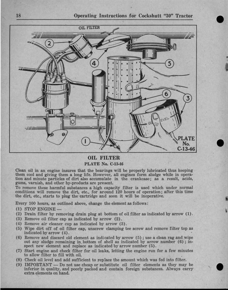
••OIL FILTER
PLATE No. C·13-46
Clean oil in an. engine insures that the bearings will be properly lubricated thus keepingthem cool and giving them a long life. However, all engi nes form sludge while in operation and minute particles of dirt also accumulate in the crankcase; as a result, acids,gums, varnish, and other by.products are present.To remove these harmful substances a high capacity filter is used which under normalconditions will remove the dirt, etc., for around 120 hours of operation; after this timethe dirt, etc., starts to plug thecartridge and soon it will be inoperative.
Every 100 hours, as outlined above, change the element as follows:(1) STOP ENGINE -(2) Drain filter by removing drain plug at bottom of oil filter as indicated by arrow (1) .(3) Remove oil filter cap as indicated by arrow (2) .(4) Remove air cleaner cup as indicated by arrow (3).(5) Wipe dirt off of oil filter cap, unscrew clamping tee screw and remove filter top as
indicated by arrow (4).(6) Remove and discard old element as indi cated by arrow (5) ; use a clean rag and wipe
out any sludge remaining in .bottom of shell as indicated by arrow number (6); inspect new element and replace as indicated by arrow number (5) .
(7) Start engine and check filter for oil leaks, lett ing the engine run for a few minutesto allow filter to fill with oil.
(8) Check oil level and add sufficient to rep lace the amount which was fed into filter.(9) IMPORTANT - Do not use cheap or su bstitute oil filter elements as they may be
inferior in quality, and poorly packed and contain foreign substances. Always carryextra elements on hand. ••
https://tractormanualz.com/
19
AIR CLEANERPLATE No. C·14-46
•
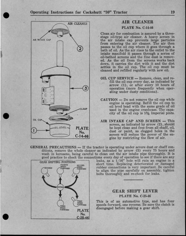
CAUTION - Do not remove the oil cup whileengine is operating. Refill the oil cup tooil level bead with the same grade of oilused in the engine crankcase. The capacity of the oil cup is 1% Imperial pints.
OIL CUP SERVICE - Remove, clean, and refill the oil cup every day, as indicated byarrow (l), or after every 10 hours ofoperation (more frequently when operating under dusty conditions).
AIR INTAKE CAP AND SCREEN - Thi sscreen, as indicated by arrow (2 ), shouldbe kept clean and free from all chaff, oil,dust or paint, as clogged holes in thescreen will reduce the power of the engine by restricting the flow of ai r.
Clean air for combustion is assured by a three-. stage oil-type air cleaner. A heavy screen in
the air intake cap prevents large particlesfrom entering the air cleaner. The air thenpasses to the oil cup where it goes through abath of oil. As the air rises to the outlet to theintake manifold it passes through a series ofoil-bathed screens and the fine dust is removed. As the oil from the screens works backdown, it carries the dirt with it and the dirtsettles in the oil cup. The oil cup must becleaned and refilled regularly with new oil.
GEAR SHIFT LEVERPLATE No. C·25-46
This is of an automotive type, and has fourspeeds forward, one reverse. Be sure the clutch isdisengaged before making a gear shift.
2
PLATENo.
C.I4-46
~-PLATE
No.·2
OJL l.~IJ~L
AIR WAKE CAP
Operating Instructions for Cockshutt "30" Tractor
GENERAL r RECAUTIONS - If the tractor is operating under severe dust or chaff conditions, remove th e whole cleaner as indicated by arrow (3) every 75 hours andwash in kerosene, being careful to clean out the air intake pipe thoroughly. It isgood practice to check the connections every day of operation to see if there are any
.----G~ SHIFTING POsmONS leaks, ~s a 1/16" ~ole will ruin an engine in aF01JIltH =OND short time. Replacmg deteriorated or damaged
g:E =AJU> Q=MD rubber connections is very important. Be carefulto align th e pipe carefully on assembly, tightenbolts thoroughly and re-ch eck for leaks.
'-.~1IIIIIi;,.
!SPD:DFORWARD
•
•
•https://tractormanualz.com/

Operating Instructions for Cockshutt "30" Tractor20
FAN BELT TENSION
PLATENo.
C-16-46
COOLING ANDOVERHEATING
PLATE No. C-I6-46
COOLING DESCRIPTION:Th e h e a t given offfrom th e engine is carri ed away by the radiator, assist ed by thehigh capacity p u m pand fan. At the blockoutlet is a special thermostat which, until theengine reaches operati n g temperature, returns the liquid to th eblock th rough th e large
. by-pass. The cylinderwalls ar e cooled b yth ermosyphon, t h u spreventing local hotand co l d spots whichmight cause distortion,and a n uneven wallwear. 'The capacity ofth e cooling system is(3) Imperial gallons,(3 Y2) U.S. gallons.
••
••CARE - Try to use rain water when filling to prevent th e addition of lime and other impurities. Fill within (1) inch of the top. DON 0 T ADD WATER TO ANENGINE THAT IS OVERHEATED OR IS PARTLY EMPTY. Wait until itcools.
OVERHEATING - As th e different units of th e cooling sys tem have been carefu lly designed and th oroughly tested, should overheating occur, check the following :
(1) Check water level in radiator , the oil pressure gauge, oil level in crankcase.
(2) Check the fan belt for slippage; it should not exceed % of an inch as shownon above plate and ind icated by the arrow.
(3) Check th e igni t ion t iming as per instruct ion on page 28.
(4) Open th e throttle fully, remove th e radiator cap and see if coolant is circulating.
(5) Examine th e radiator hose for deterioration and replace if rubber is loose inthe inside.
(6) The radiator core protective screen may be plugged. Blowout with an airline or water hose from th e back .
(7) The radiator or block may plug with foreign matter: To clear; drain out system, th en f ill with solut ion of 1% pounds of ordina ry washing soda to 3 Imperial gallons of water , then run eng-ine until hot, with radiator cap off. Stop th eengine, drain soluti on, refill with clear water.
••https://tractormanualz.com/
•• Operating Instructions for Cockshut t "30" Tractor 21
WATER DRAIN '
&
c
ENGINE BLOCK
,
-~
PLAT ENo,
C·26-46
•• DRAINING SYSTEM
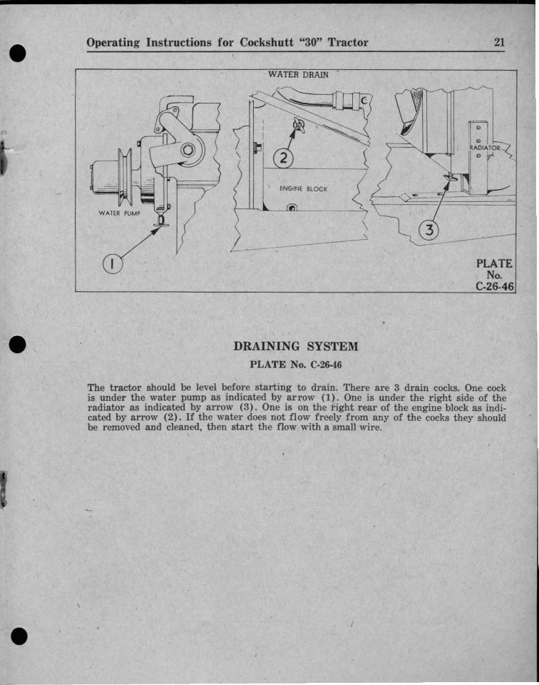
PLATE No. C·26-46
The tractor should be level before starting to drain, There are 3 drain cocks, One cockis under th e water pump as indicated by arrow (l). One is under th e right side of th eradiator as indicated by arrow (3). One is on th e r ight rear of th e engine block as indicated by arrow (2). If th e water does not flow freely from an y of th e cocks th ey shouldbe removed and cleaned, th en start th e flow with a small wire.
••https://tractormanualz.com/
•
PLATENo.
C-27-46
o
STEERING COLUMN
REAR GEAR
THRome CONTROL LEVER
Operating Instructions for Cockshutt "30" Tractor
LIVE POWER TAKE-OFF
CROSS SECTION VIEW
DRAW BAR
22
https://tractormanualz.com/

• ~Operating In structions for Cockshutt "30" Tractor
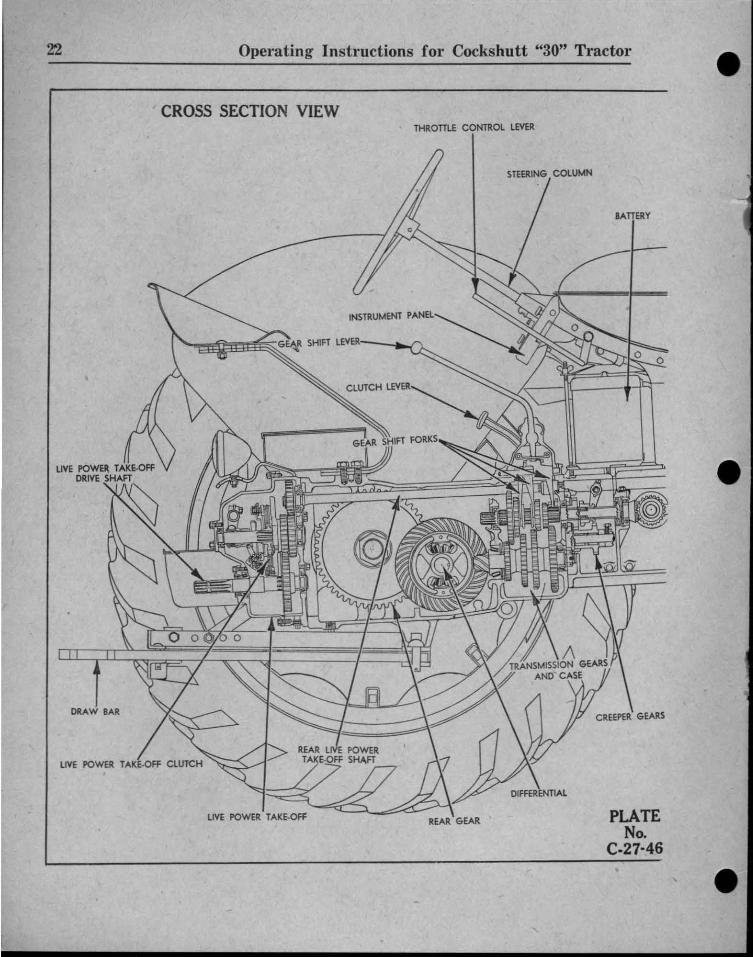
CROSS SECTION VIEW
23
FUEL TANK
AIR CLEANER F=±l MUFflERI
,~
SEDIMENT BOWL
CLUTCH
FRONT lIV E POWERTAKE·Off SHAFT
THERMOSTAT
VALVEPUSH RODS
GENERATOR
OIL PUMP AND SCREEN
STEERING POST
CARBURETOR
PLATENo.
0 .27-46
https://tractormanualz.com/
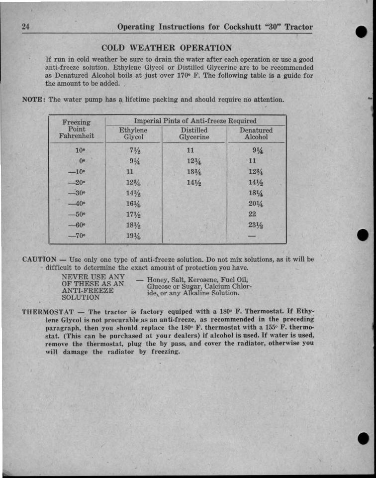
NOTE: The water pump has a lifetime packing and should require no attention.
CAUTION - Use only one type of anti-freeze solution. Do not mix soluti ons. as it will bedifficult to determine the exact amount of protection you have.
NEVER USE ANY O·OF TH ESE AS AN - Honey. Salt. Kerosene•.Fu el II,ANTI-FREEZE 9 1ucose or Sugar! Calcium Chlor-SOLUTION Ide. or any Alkahne Solution,
THERMOST AT - Th e tractor is factory equiped with a 1800 F. Thermostat. If Ethylene Glycol is not procurable as an anti-freeze, as recommended in the precedingparagraph, then you should replace the 1800 F. thermostat with a 1550 F. thermostat. (This can be purchased at your dealers) if alcohol is used. If water is used,remove th e th ermost at, plug th e by pass . and cover the radiator, otherwise youwill damage th e ra diator by freezing.
•
Freezing Imperial Pints of Anti-freeze RequiredPoint Ethylene Distilled Denatured
Fahrenheit Glycol Glyceri ne Alcohol
100 7Y2 11 91A,
00 91,i 12%. 11
_ 100 11 133,i 123,4
-200 12%. 14Y2 14Y2""":300 14Y2 181A,
-400 161A, 201A,
-500 17Y2 22
-600 18Y2 23Y2
-700 191A, -
Operating Instructions for Cockshut t "30" Tractor
COLD WEATHER OPERATIONIf run in cold weather be sure to drain the water after each operation or use a goodanti-freeze solution. Ethylene Glycol or Distill ed Glycerine are to be recommendedas Denatured Alcohol boils at ju st over 1700 F. The following table is a guide forthe amount to be add ed. •
24
https://tractormanualz.com/

••
• Operating Instructions for Cockshutt "30" Tractor 25
WIRING COLOUR CODE FOR IGNITION HARNESSGENER ATOR n£LO TO WC HT SWITCH • RED WITH DOUBIL WH ITE: Tlffi £A D
GENI:RATOR CUTOUT TO AMMETER G REEN WITH DOUBLE YEllOW THREAD
STARTER TO AMMETER YELLOW WITH TRIPLE BLACK nOU:AD
UGHT JUNCTION TO UG Hl SWITCH . . RED WITH mIPLE WHITE THREAD
IGNmON SWITCH TO COIL • BLACK WITH DOUBLE WHITE THREAD
RIGHT AND UTT HA."lO UGHl WIRES YEllOW WITH DOUBU: BLACK THREAD
••TO·7~;Z
[j. ) TO·7!l34
ft£:JtIT====TO.""1-1- IL.: TO·7!172
IL "':'--TO.7!l38
INSTRUMENT PANEL
.-- - .. ._ .. .....~~..... ...."B Cj j
TO·1~39
--rO.7!l72
LIGHT SWITCH AND GENERATOR CO NTROL
PLATE·No.
C-I0-46
••
ELECTRIC AL S Y S T E M
PLATE No. C-I0-46
GENERAL DESCRIPTION - The elect r ical system of your Tractor may be compared tothe water works of a city. The generator is th e pumping station; the battery; thewater tank whi ch stores th e elect rici ty ; th e wires, th e ma ins which carry th e current; and the light , starter, and ignition system, the un its which use the current orwater.
Controls are provided to adjust the flo w of cur rent just as valves are required inthe main. A switch is required for th e lights, th e starter, and th e ignition system,and in combination with the light switch there is an ext ra position to control th ecurrent flow from the generator to the battery to prevent overcharg ing th e battery iu st as controls are used at th e water works to keep th e water tank fromoverflowing. In order to keep th e cur rent f lowing cor rectly th ere must be goodconnect ions to prevent obstructing th e cur rent and there must be no leaks, such asworn insulation or corroded battery terminals.
To provide ignition of the combustible mixture in th e cylinders the voltage or pressure of th e cur rent coming from th e generator is not high enough so it is necessary to step it up by means of a coil. From th e coil it goes to one cylinder at atime through the distributor.
https://tractormanualz.com/
DETAILED DESCRIPTION - The operato r should examine the wiring diagram, PlateNo. C-I0 -46, to understand th e elect r ical system thoroughly .
COMBINATION LI GHT SWITCH AND GENERATOR CONTROL - As described onpage 22, this switch has three positions: (a) Full In- Low Rate Charge; (b) HalfOut- High Rate Charge ; (c) Full Out-Lights on the Generator Full Charge, asindicated by arrow (l) . The tractor operator is of necessity responsible for thecorrect use of the switch. Remember that overcharging will damage the battery.
STARTER - The starting motor which provides the power to crank th e engine througha conventional bendix drive requires little attention. except to see that th e cableson the switch are clean and tight, an d that the insulation on th e wires is not corroded or damaged. It is a good idea to occasionallv check the three cap screwsholding th e starter to th e flywheel cover to see that they are t ight . No oiling isrequired on the unit as bushings with lifet ime lubri cat ion are provided .
•
•
Operating Instructions for Cockshutt "30" Tractor
GENERATOR - The generator provided is of the dust-proof third brush type, andin normal condit ions requires little attention except the addition of 4 or 5drops of S.A.E. 20 or 30 engine oil every 60 hours to the oiler at the front andat the rear bearings. When oiling the generator it is a good idea to also check thewiring for loose connection ; and worn insulation. In most cases th e third brushneed not be adjusted to control the rate of charge as this can be conveniently doneby means of the combination light switch and generator control. If the generatorgives trouble, it is suggested that your local dealer be contacted and he will giveth e generator the proper service to restore it to its original condition.
CORRODED TERMINALS - During th e weekly inspection outlined above. examine th eterminals for corrosion. ann if presen t, wash off with hot water which may also beused for cleaning the top of th e battery. Be sure to use sufficient water to wash allthe corrosion down through the box and to th e zround . as corrosion, even whenwash ed away from the terminals. is still active and can damage the box badly. Twoto three times a year remove the ter minals. wash them as outlined above, thenbrighten th em UP with wire wool, apply a light coat of vaseline and reassemble,being sure to tighten the terminals carefu lly.
26
BATTERY - The battery which sto res the elect rical energy, just as the water ta nk storeswater for a city . does so in a chemical form. A regular routine should be establishedfor attending the battery as there is no better way to insure. that it will give youlong trouble-free service.
To service th e battery, take off th e battery cover after removing the wing nutann th e battery hold-down clamp.
Once a week or oftener inspect th e wa tel' level ann bring it three-eighths of an inchabove th e plates by adding distilled or clean soft water. Adding more than thismay mean that when th e battery is warm th e water may overflow through thevents. causing' corrosion. At th e sam e time th e specific gravity should be checkedann if below 1225, the tractor should be onerated with the light switch in the"Hizh Charge" position a zreat er portion of th e tim e. and if up to full charge, 1270to 1285, th e "Low Charge" rate should be used a greater portion of the time.
In cold weather batteri es mav freeze if not kent properly cha rged. A partly chargedhatterv will freeze at 20· F. above zero while a fully charged battery will stand 45· to 50·F. below zero.
The battery should also be kept at a higher rate during cold weather as th e demands fromthe starter are greater.
If th e tractor is not being used during cold weather the battery should be removed andleft at your dealer's for proper attention and care.
https://tractormanualz.com/
• • Operating Instructions for Cockshutt "30" Tractor 27
CAUTION - During the weekly inspection, check the terminals for tightness and thecables for corrosion and wear.
IGNITION COIL - The ignition coil serves to step up the low battery voltage to the highvoltage necessary to jump the spark plug gaps.
Due to their construction, ignition coils do not require any service other than tokeep all connections and terminals clean and tight.
• 69
2
TO ADJUST CHARGING RATEOF THIRD BRUSH
Third brush is shown se t3.2 commutator bars hommain brush.
Main brush(g round ed)
~
Commutator bar
PLATENo.
C-23-46
•
.
•
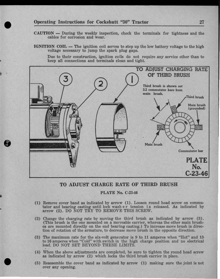
TO ADJUST CHARGE RATE OF THIRD BRUSH
PLATE No. C-23-46
(1) Remove cover band as indicated by arrow (1). Loosen round head screw on commutator and bearing casting until lock wash e r tension i s released. As indicated byarrow (2). DO NOT TRY TO REMOVE THIS SCREW.
(2) Change the charging rate by moving the third brush as indicated by arrow (3) .(This brush is the one mounted on a moveable carrier, whereas the othe r main brushes are mounted directly on the end bearing casting.) To increase move brush in direction of rotation of the armature, to decrease move brush in the opposite direction.
(3) The maximum rate for the six-volt generator is 9 to 11 amperes when "Hot" and 13·to 16 amperes when "Cold" with switch in the high charge position and no electricalload. DO NOT SET BEYOND THESE LIMITS.
(4) When the above adj ustments are completed, be sure to t ighten the round head screwas indicated by arrow (2) which locks the third brush carrier in place. .
(5) Reassemble the cover band as indicated by arrow (1) making sure the joint is notover any opening. https://tractormanualz.com/
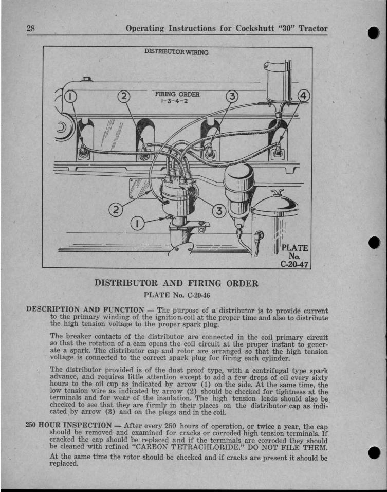
DESCRIPTION AND FUNCTION - The purpose of a distributor is to provide currentto the primary winding of th e ignitio n.coil at the proper time and also to distributethe high tension voltage to the proper spark plug.
Th e breaker contacts of the distributor are connected in the coil primary circuitso that the rotation of a cam opens the coil circuit at the proper instant to generate a spark. Th e distributor cap and rotor are arranged so that the high tensionvoltage is connected to the correct spark plug for firing each cylinder.
The distributor provided is of th e dust proof type, with a centrifugal type sparkadvance, and requires little attention except to add a few drops of oil every sixtyhours to the oil cup as indicated by arrow (1) on the side. At the same time, thelow tension wire as indicated by arrow (2) should be checked for tightness at theterminals and for wear of the insula tion. The high tension leads should also be .checked to see that they are firmly in th eir places on the distributor cap as indicated .by arrow (3) and on the plugs and in the coil.
250 HOUR INSPECTION - After every 250 hours of operation, or twice a year, the capshould be removed and examined for cracks or corroded high tension terminals. Ifcracked the cap should be replaced a nd if the terminals are corroded they shouldbe cleaned with refined "CARBON TETRACHLORIDE." DO NOT FILE THEM.At the same time the rotor should be checked and if cracks are present it should bereplaced.
28 Operating Instructions for Cockshutt "30" Tractor
DISTRIButOR WIRING
IIII! !Ipll' l
I11111PLATE
No.C-20-47
DI STRIBUTOR AND FIRING ORDERPLATE No. C·20-46
https://tractormanualz.com/
•
•
• Operating Instructions for Cockshutt "30" Tractor
'---
PLATENo.
C. 19-46
29
• •
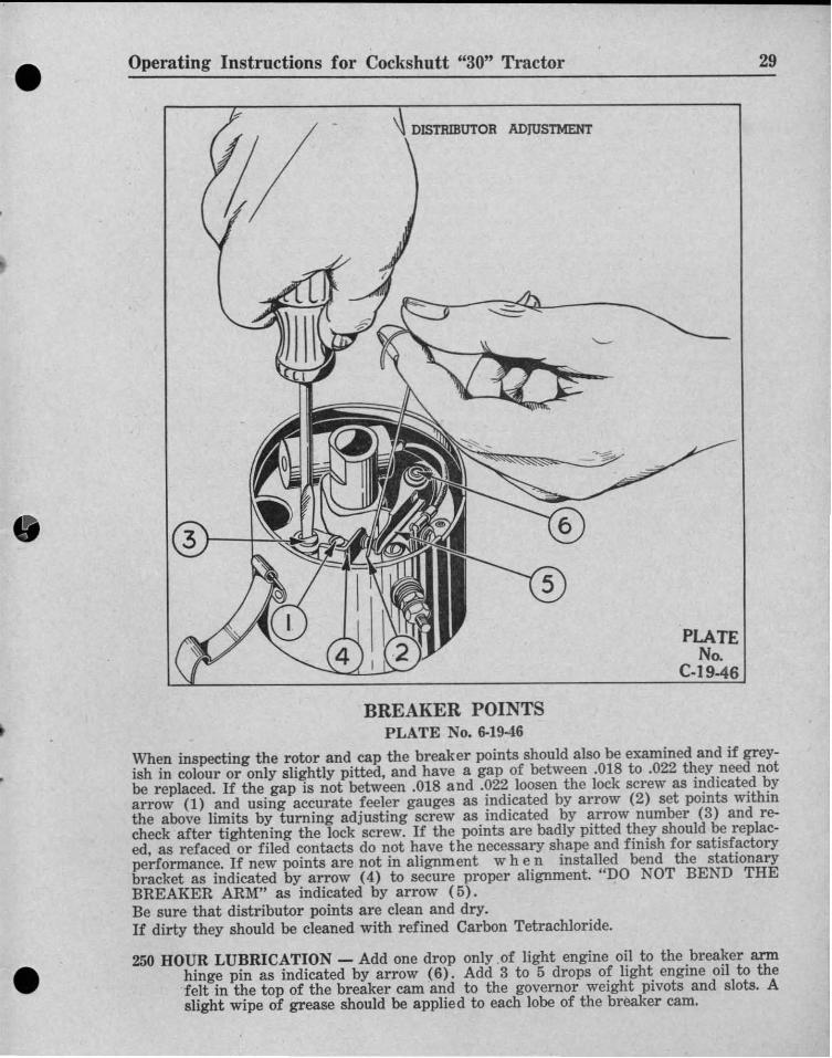
BREAKER POINTSPLATE No. 6-19-16
When inspecting the rotor and cap the breaker points should also be examined and if greyish in colour or only slightly pitted. and have a gap of betw een .018 to .022 they need notbe replaced. If th e gap is not between .018 and .022 loosen the lock screw as indicated byarrow (l) and using accurate feeler gauges as indicated by arrow (2) set points withinthe above limits by turn ing adjusting screw as indicated by arrow number (3) and recheck aft er tightening th e lock screw. If the points are badly pitted they should be replaced. as refaced or filed contacts do not have the necessary shape and finish for satisfactoryperformance. If new points are not in alignment w h en installed bend the stat ionarybracket as indicated by arrow (4) to secure proper alignment. " DO NOT BEND THEBREAKER ARM" as indicated by arrow (5) .Be sure that distributor points are clean an d dry.If dirty th ey should be cleaned with refined Carbon Tetrachloride.
250 HOUR LUBRICATION - Add one drop only .of light engi ne oil to the breaker armhinge pin as indicated by arrow (6) . Add 3 to 5 drops of light engine oil to thefelt in the top of the breaker cam and to the governor weight pivots and slots . Aslight wipe of grease should be applied to each lobe of th e breaker cam.
https://tractormanualz.com/
•HEAD LIGHTS - Keep connections clean and tight and the nuts on the clamps sup
porting the lights tight to prevent excessive vibration.
PLATENo.
C·22-46
Operating Instructions for Cockshutt "30" Tractor30
STEERING GEAR
TIMING OF DISTRIBUTOR - If the distributor has been removed from the engine it iswise to ret ime it in relation to the crankshaft. To do this, make up two wireswith small clips on one end, th e other ends being connected to the terminals of dashlamp bulb. Fasten one clip to the terminal on the side of the distributor and theother clip to the screw on th e advance arm. Then remove the plug in the right frontof th e rear engine mount and crank the engine slowly until the marks I.G.N. are justpassing the hole. When the marks are in the centre of the hole the light should goon and th e rotor point should be adjacent to the outlet on the cap leading to No.1cylinder. If this is not so, loosen the clamp screw on the advance arm and turnthe distributor until the correct timin g is secured. After the setting is done be sureto tighten the screw and rech eck by again turning the crank slowly and replacethe plug in the engine mount when th rough.
SPARK PLUG CABLES - If the spark plug cables are removed note the position of thecables on the distributor as illustrated on plate No. C-20-46, on page 26. .
CLEANING SPARK PLUGS - Never scrape or clean the insulation with anything thatwill scratch the porcelain. Sand blasting is much better and can be done at mostservice stations.
SPARK PLUGS - Champion J5 Spark Plugs are used and every 200 to 300 hours theyshould be removed for cleaning and checking. A gap of .025 should be maintainedand when making this adjustment always bend the outer electrode.
https://tractormanualz.com/

• • Operating Instructions for Cockshutt "30" Tractor
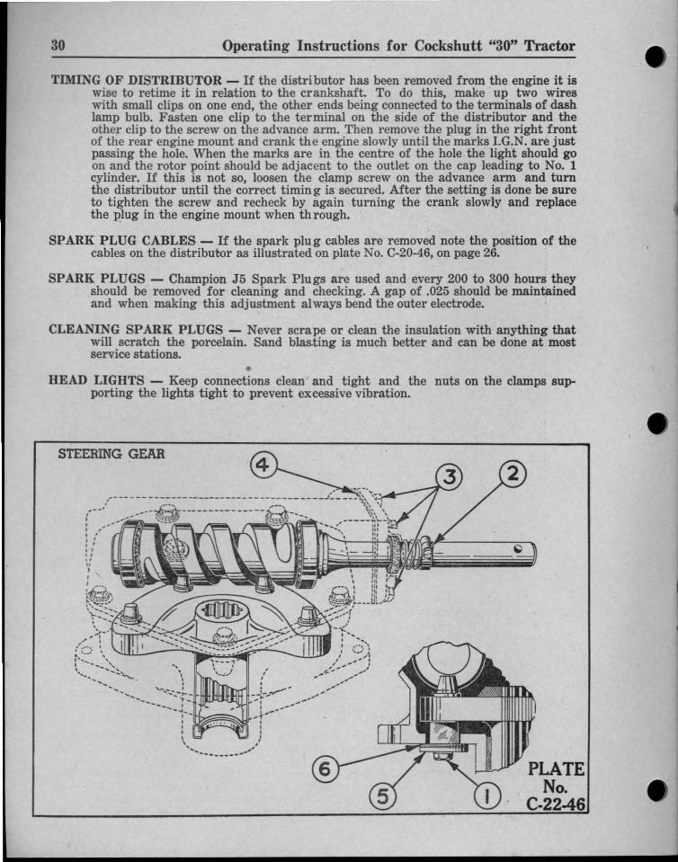
STEERING GEAR ADJUSTMENTPLATE No. C-22-16, on Page 30
31
•
•
•
•
There are two adjustments on this steering gear. Both a re shim adjustment.
(1) To adjust the ball thrust bearing on th e cam to a barely perceptible drag loosenthe two cap screws as indi cated by arrow number (1) , holding th e adjusting pad inorde r to free the studs in the cam groove. Release th e clamp as indicated by arrownumber (2) of the oil seat unit. Unscrew th e fou r cap screws as indicated by arrownumber (3) and move out cover to permit removal of shims. (Shims are of .902",.003", and 010" thickness. Clip and remove a thin shim as indicated by arrow (4) ormore as required. Tighten all four cap s crews. Test adjustment and if necessary remove or add shims until adjustment is cor rect. Replace cover and reset clamp of oilseat unit and tighten.
(2 ) To adjust backlash of tapered studs in cam groove so that a very slight drag is fe ltwhen gear is turned from ext reme left pos ition or ext reme r ight position, or viseversa. Remove adjusting pad as indicate d by arrow number (5) to permit removal ofshims. (Shims are of .003", .007", and .010" thickness.) Remove one thin shim as indicated by arrow number (6) or as requir ed. Reassemble pad and shims and t ighten.Test adjustment and if necessary repea t operation by removing or adding shims unt iladjustment is correct.
STEERING MECHANISM AND FRONT WHEELS
STANDARD WIDE AXLE TRACTOR - Carefu lly designed for easy steering, th e mainunits are made of tough steel forgings accurately machined to secure good alignment. The latest type of easy action tie-rod is used to connect the highly effi cientsteer ing gear to the front wheels.
CARE - To maintain easy steering and to prolong life grease all fittings and service th esteering gear as descri bed on page 9. Adding new grease is an excellent mean s ofrepelling dirt and other foreign matter.
WHEEL ALI GNMENT OF STANDARD WIDE AXLE TRACTOR - To check alignment, first check wheel bearing adjustment as described below th en jack the frontend up so that the wheels are free to turn, meas ure th e distance between the insides of the tires at hub height, in front of the axle, turn each wheel exactly onehalf turn and measure between th e sa me points behind the axle. The measurementtaken in front of th e axle should be % less, and if not, loosen th e ti e rods, turn eachone the same amount and re-measure. Turning the wheels one half turn as described above eliminates any errors due to weave in the wheel disc.
FRONT WHEEL BEARI NG ADJUSTMENT - Frequently one should jack up eachfront wheel, try moving the wheel fr om side to side and if even th e slightestmovement is present betw een th e wheel and hub remove th e hub cap and pull thecotter pin . Then tighten the adjusting nut while at the same time turning the wheelby hand until slight binding is felt . The nut should then be backed off until the cotte r pin will go in either th e hor izontal or vertical hole in th e spindle. If it happensthat th e binding is noticed just when t he cotter pin is in line with one castellation itis better to back th e nut off until th e next castellation is in line with the othercotter pin hole to prevent the beari ng from being too tight. Be sure to use a newcotter pin if any cracking is present. BE CAREF UL to keep dirt or other foreignmatter out of the grease or hub cap, which may now be assembled. Occasionallyone should go over the nuts on th e hu bs, radius rod end and steering arms to see ifth ey are tight.
https://tractormanualz.com/

PNE U M ATIC TIRESMOUNTING OF TIRES ON RIMS - After rear tires a re mounted on the rims they
should be inflated to 30 pounds pressure in order to force the t ire beads firmly intothe r ims. The rim and tire are tapered, so this pressure is necessary in ord er toforce the beads firmly into place. ilIIII ; ~
The tire should be inflated to 30 poun ds pressure every time the t ire bead is pushedaway for or from the rim seat at any point. Then the pressure should be droppedto the recommended pr essure as given in t h e following paragraph, "INFLATION."This practice should be followed, as otherwise the ti re will slip on the r im andshear off the valve stem.
INFLATION - Inflation to the proper air pressure is the most important factor in thesatisfactory performance and maintenance of t ractor t ires. For the front t ires,5.50 x 16, the proper air pressure is 28 pounds, and for the rear tires, 10.00 x 38,it is 12 pounds , except when plowing, when the pressure in the rear furrow tiresliould be increased by 4 pounds, giving 16 pounds pressure.Both under inflation and over inflation are harmful. Under inflation will damagethe cord body of the tire. It will cause a series of diagonal breaks in the cord fabricin the sidewall area. This usually occurs on the inner side wall of the furrowwheel tire. Under inflation will re sult in repeated buckling of the sidewall and constant buckling will break the cord fa bric.Inflat ion should always be high enough, especially in the furrow wheel, so that thet ire will not buckle. The buckling ca n be seen, especially on hard pulls, by thedriver or someone walking along the side of the tractor . If the tire buckles orwrinkles the air pressure should be increased to the point where the sidewalls remain smooth while the tractor is pulling on the tire. Under inflation may alsoallow the tire to slip on the rim, which in turn will tear off the valve stem of thetube. Over inflation should also be avoided. It causes loss of traction, which resultsin excessive slippage, causing tires t o wear more rapidly.
METHODS OF INFLATION - Inflation with a hand pump is not difficult when only afew pounds are needed to inflate to the recommended pressure.Spark plug tire pumps which will infl ate the t ire in from 5 to 6 minutes can be purchased from your dealer.
AIR PRESSURE SHOULD BE CHECKED FREQUENTLY - Air pressure should bechecked every week, and should not be allowed to drop below the recommendedpressure. A special low pressure gauge, with one pound gradua t ions (such as aSchrader No. 9350) is necessary in order to get accurate inflation. Gauges shouldbe checked occasionally at a tire service station, as they get out of order and acorrection in the reading might have to be made. Always use caps on the valves asthi s prevents loss of air. It is not ad visable to reduce air pressure in order toincrease t ract ion as damage to t ire is likely to result.
CARE OF TIRES - To insure the maximum of hours of service, watch the tread lugs if they wear too fa st , immediately add more weight.To cut down the slippage, check for high ai r pressure. Keep tires free from oil orgrease, and avoid driving over sharp obstacles, such as stones, etc., which mightcut the tires. All cuts should be repaired immediately.
TIRE PROTECTIO N DURING STORAG E - When not in use your t ractor should bestored so that the tires are protected from the light. Before storing, the tiresshould be thoroughly cleaned with wa tel'.If it is to be stored for a long period, jack it up so that the load is off the tires.If it is not jacked up, tires should be checked at regular intervals for proper inflat ion.
AIR PRESSURE ON TR ACTORS TO BE SHIPPED - When a tractor is transportedby rail or truck, all 4 ply front ti res should be infl ated to 30 pounds ; all 6 plyfront tires to 36 pounds; all rear t ires to 30 pounds. This makes possible rigidblocking and prevents bouncing.
IMPORTANT - After the tractor is unload ed, and before the tractor is operated, be careful to deflate the tires to the correct pressures, as given in a preceding paragraph.
32 Operating Instructions for Cockshutt "30" Tractor
https://tractormanualz.com/

• • Operating Instructions for Cockshutt "30" Tractor
BELT PULLEY DRIVE
33
BELT PULLEY
•
•
•
TRANSMISSION SHAFT
~
CLUTCH LEVER(IN DISENGAGED POSITION)
BELT PULLEY SHIFTPLATE No. C·15-46
>---.-...J ALWAYSKEEPNUT
TIGHT
PLATENo.
C-1 5-46
• •
CARE OF BE LT P ULLEY - It is suggested that when considerable field work is to bedone. that the belt pulley and shifting case be removed as a unit to prolong thelife of th e Rockwood pulley. First -d r ive the tractor up on an incline or jack up th eright side or pulley side of th e tractor. This will prevent the oil running out whenth e pulley and shafting case is removed and will then make it unnecessary to drainthe oil to remove the unit. To remove the unit, remove the cap screws that holdit to th e tractor frame and pull it ou t, being careful to keep it free of dirt and foreign matter. Wire the shims to the uni t to prevent loss, store in a clean place. Installth e special cover plate, which is supplied with four cap screws. If th e tractor isleft out in the weather with th e pulley on, the pulley should be covered with ashield to prevent damage by the elements to which it is exposed.
To engage or disengage th e pulley drive, with the engine running, depress th e mainclutch pedal and shift it in or out as desired. When starting up a heavy separator or other machines release the clutch gradually to prevent undue belt slippageand troublesome starting. CAUTION : To avoid static electricity when doing beltwork, ground the tractor with a short chain.
BELT P ULLEY SHI FT - Before th rowing the belt clutch in or out of gear. let the tractor idl e and then fully depress clutch pedal. This is necessa ry, so that the pulleysp line sha f t will not he damaged when cha nging gea rs.
https://tractormanualz.com/

Operating Instructions for Cockshutt "30" Tractor34
BRAKELINING
CROWN GEAR
FORGED STEElBUU GEAR
TOP VIEW OfTRANSMISSION
MAIN AXLES
LOWER TRANSMISSION SHAFT
BRAkE DRUM
PLATENo.
C.12-46
https://tractormanualz.com/
• • Operating Instructions for Cockshutt "30" Tractor
TRANSMISSION
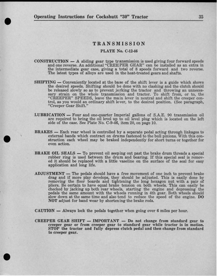
PLATE No. C·12-46
35
• •
CONSTRUCTION - A sliding gear type transmission is used giving four forward speedsand one reverse. An additional "CREE PER GEAR" can be installed as an extra inthe intermediate gear case, giving a total of 8 speeds forward and two reverse.The latest types of alloys are used in the heat-treated gears and shafts.
SHIFTING - Conveniently located at the base of the shift lever is a guide which showsthe desired speeds. Shifting should be done with no clashing and the clutch shouldbe released slowly so as to prevent jerking the tractor and throwing an unn ecessary strain on the whole transmission and tractor. To shift from, or to, the"CREEPER" SPEEDS, leave the main lever in neutral and shift the creeper control, as you would an ordinary shift lever, to the desired position. (See paragraph,"Creeper Gear Shift."
LUBRICATION - Four and one-quarter Imperial gallons of S.A.E. 90 transmission oilare required to bring the oil level up to oil level plug which is located on the leftside of the case. See Plate No. C-9-46, item 20, on page 10.
BRAKES - Each rear wheel is controlled by a separate pedal acting through linkages toexternal bands which contract on drums fastened to the bull pinions. With this construction each wheel may be braked independently for short turns or together foreven action.
BRAKE OI L SEALS - To prevent oil seeping out past the brake drum threads a specialrubber ring is used between the drum and bearing. If this special seal is removed it should be replaced with a little vaseline on the surface of the seal for easyapplication and long life.
ADJUSTMENT - The pedals should have a free movement of one inch to prevent brakedrag and if more play develops, they should be adjusted. This is easily done byremoving the floor boards and tightening the long hexagon nut with a pair ofpliers. Be certain to have equal brake tension on both wheels. This can easily bechecked by jacking up both rear wheels, starting the engine and depressing thepedals the same amount with the wheels running in 4th gear. Both wheels shouldslow down at the same time and also tend to reduce the speed of the engin e. DONOT adjust for band wear by shortening the brake rods.
CAUTION - Always lock the pedals together when going over 6 miles per hour.
CREEPER GEAR SHIFT - IMPORTANT - Do not change from standard gear tocreeper gear or from creeper gear to standard gear while tractor is in motion.STOP the tractor an d fully depress clutch pedal and then change from standardto creeper gear.
• • https://tractormanualz.com/
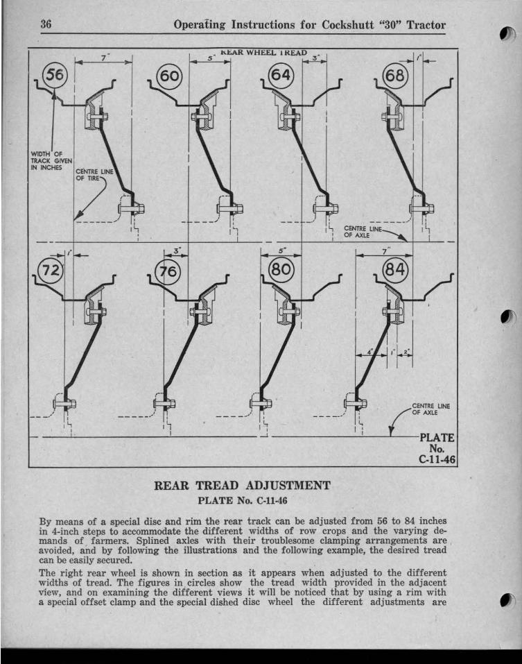
By means of a special disc and rim the rear track can be adjusted from 56 to 84 inchesin 4-inch steps to accommodate the different widths of row crops and the varying demands of farmers. Splined axles with their troublesome clamping arrangements areavoided, and by following the illustrations and the following example, the desired treadcan be easily secured.The right rear wheel is shown in section as it appears when adjusted to the differentwidths of tread. The figures in circles show the tread width provided in the adjacentview, and on examining the different views it will be noticed that by using a rim witha special offset clamp and the special dished disc wheel the different adjustments are
Operati ng Instructions for Cockshutt "30" Tractor
CfNTRE LINEOF AXLE
/'g~NTR' LIN'
L AX"
-----:....!-- PLATENo.
C·ll ·46
---_./
"tAR WHEEL 1KEAD5 '
REAR TREAD ADJUSTMENTP LATE No. C-1l-46
36
WIDTH OFTRACK GIVtNIN INCHES CENTRE LINE
OF nRE
https://tractormanualz.com/
• Operating Instructions for Cockshutt "30" Tractor 37
easily secured. Bearing in mind that more efficient traction is secured when tires are runin the direction specified on them, the tires from the opposite wheel should be used whentread with widths 64, 68, 80 and 84 are used.
EXAMPLE - To use a tread width of 80 inches when the tread has been set for 56inches, jack up the rear wheels carefully and block the front wheels to preventshifting, remove the rim bolts, and the bolts holding the disc to the hub. Thenshift the tires to the opposite side of the tractor, re-install the discs on the hubwith the dished side out, then mount the rims to the discs with the clamp insidethe disc. TI GHTEN ALL BOLTS AND NUTS SECURELY.
• • \\ ,. ',I -.~_ # \\ t.
REAR WHEEL WEIGHTSPLATE No. C·24-46
e
PLATENo.
C.24-46
• •
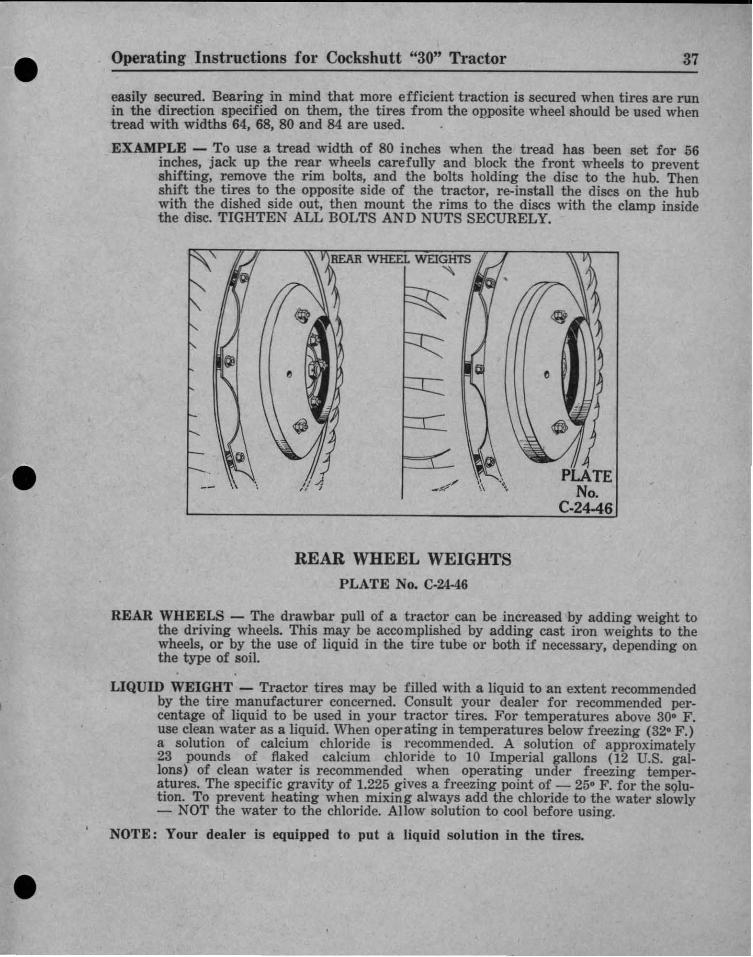
REAR WHEELS - The drawbar pull of a tractor can be increased by adding weight tothe driving wheels. This may be accomplished by adding cast iron weights to thewheels, or by the use of liquid in the tire tube or both if necessary, depending onthe type of soil.
LIQUID WEIGHT - Tractor tires may be filled with a liquid to an extent recommendedby the ti re manufacturer concerned. Consult your dea ler for recommended percentage or liquid to be used in your tractor tires. For temperatures above 30° F.use clean water as a liquid. When operating in tem peratures below freezing (320 F.)a solution of calcium chloride is recommended. A solution of approximately23 pounds of flaked calcium chloride to 10 Imperial gallons (12 U.S. gal.Ions ) of clean water is recommended when operating under freezing temper.atures . The specific gravity of 1.225 gives a freezing point of - 25° F. for the solution. To prevent heating when mixing always add the chloride to the water slowly- NOT the water to the chloride. Allow solution to cool before using.
NOTE: Your dealer is equipped to put a liquid solution in the tires.
https://tractormanualz.com/

H I TC H
STORING AND HOUSING YOUR TRACTORWhen your tractor is not to be userl for a period of tim e, it should be stored in a dryand protected place. Leaving equipment. exposed to th e weather, for even short periods,materially shortens its life as useful equipment.
Operating Instructions for Cockshutt "30" Tractor
Drain and flush the cooling syst em thoroughly, making sure all three drain cocksare opened.
Remove the battery. Clean it off with h ot water and leave it at your dealers for proper attention and care while not in use.
(3 )
(2)
The following procedure is recommended for storing your tractor, and the lubricationprecautions should be repeated every 6 months th ereafter.
(1) Wash or clean and completely lubricate the tractor, referring to the "LubricationChart."
ADJ USTMENT - In all cases th e hitch should be adjusted so that the centre lineof pull of th e tractor will fall in lin e with, or at least nea r, the centre line ofdraft of the hitch on th e implement: Incor rect hitch ing will r esult in difficultstee r ing and unsat isfactory work of the implement and causes unnecessary strainon the t ractor, and implement , being sufficient in some cases to cause permanent damage. Make f ull use of the range adj ustment provided by the holes in th ebraces to the tractor axles and by th e sideways adjustment provided by th e holesbraces to the tractor axles and by th e sideways adjustment of the drawbar in th edrawbar frame.
DRAW BAR P ULL - Your tractor will develop more draw bar pull in pounds if thetires are fill ed with a calcium chloride solution. Less slippage and less tire scruffin!: and longer tire life will be secured by fill ing the tires with calcium chloride.
CAST WEIGHT - The drawbar pull of a tractor can be increased by adding cast ironwheel weights. They are available from your dealer in sets of two, one for eachrear wheel. Each weighs approximately 140 pounds . For add ed traction, one or twosets of weights may be installed, as shown in Plate No. C-24-46, Page 37.
CAUTION : OVERLO ADI NG - Do not load th e t ires beyond their rated capacity. Inadd ing weights consideration must be given to the load capacity of the tire.
TIRE PROTECTIO N DURI NG STORAGE - When not in use your tractor should bestored so that the tires are protected from the light. However, before storing, thetires should be thoroughly cleaned with water.
If it is to be stored for a long period, jack it up so that the load is off the tires.If it is not jacked up, tires should be checked at regular intervals for proper inflation.
38
https://tractormanualz.com/
• Operating Instructions for Cockshutt "30" Tractor 39
(l)
(2)
(3)
(4)• • (5)
(6)
(7)(8)(9)(10)
(ll)
(12)
,
•
• •
(4) Let the engine cool off then remove the spark plugs and pour one tablespoonful ofS.A.E. 50 lubrication oil into each cylinder. Now turn engine over , 2 or 3 revolutions,to evenly distribute the oil over the cylinder walls. Th en replace spark plugs.
(5) Remove valve housing cover and remove any rust found. Then flush valves, push rods,and rocker arms, with S.A.E. 50 lubricating oil. Replace valve housing cover.
(6) Remove oil filter element and, after cleaning th e filter, replace with a new element.
(7) Plug the ends of the breather pipe and exhaust pipe.
(8) Drain fuel tank and carburetor, and then clean out fuel strainer glass bowl.NOTE: Gum formed in fu el tank lines and carburetor while in storage may be dissolved with "Acetone" or a 50-50 mixtu re of alcohol and benzol.
STARTING ENGINES THAT HAVE BEEN IN STORAGE
Remove valve housing cover and flush valves and valve operating mechanism witha mixture of one-half gas oline and one-half light lubricating oil.
Remove spark plugs and pour two tablespoonfuls of the sam e mixture into eachcylinder.
Crank engine rapidly until excess oil has been blown out of spark plug holes. Thiswill also loosen tight piston rings and wash gummy oil from valves and pistons.
Drain crankcase, flush out with kerosene and fill with lubricating oil as specifiedin "Lubrication Chart."
Check oil filter to see if the new element is installed.
Remove plugs from breather pipe and exhaust pipe.
After cleaning and setting gaps install the spark plugs.
Close all THREE drain cocks in the cooling system and fill with clean water.
Fill fuel tank.
Clean air cleaner and refill the oil cup .
Install a fully charged battery, making sure connections are cleaned, lightly greasedand tight.
Start the engine and let it operate slowly; check for sticking valves. If any, poura little kerosene on valve stem.
(l3) Replace valve housing cover.
CAUTION - Do not accelerate engine rapidly or operate at a high speed immediatelyafter starting it.
https://tractormanualz.com/

•
. --. .- -:~- -.-. '\. '~\J_ 1· ' · ... ""'-.
-'.. -
Always insist on genuine Cockshutt repair
parts: For better fit and greater durability.
, r ~;.... .
. _... - ---- -:: ' . ' .::
https://tractormanualz.com/