Cockpit Description
5
Click on each instrument for detailed description. Always consult a qualified flight instructor for proper use & reading of these instruments. Please note that this is a typical cockpit layout of a Cessna 172 and does not necessarily represent the exact equipment installed in MEA rental aircraft. Lower panel - Left to Right IGNITION SWITCH [up] MASTER SWITCH This is actually 2 switches side b y side, one for the battery and one for the alter nator [up] TOGGLE SWITCHES For landing & navigational lights & other accessories. [up] CIRCUIT BREAKERS (white round buttons) For all electrical equipment. [up] AVIONICS MASTER SWITCH Powers on the radio stack [up] PANEL LIGHT DIMMERS (black knobs with silver center) Adjusts lighting intensity of the panel and radio lighting. [up] THROTTLE (Large black knob) Adjusts aircraft engine power(thrust). [up] MIXTURE CONTROL (Large Red Knob) Adjusts fuel mixture. [up] ALTERNATE STATIC AIR (Small red knob) Used in case of static port clog or static system failure. [up] FLAPS LEVER (White lever) Use to extend and adjust degrees of flaps. [up] CABIN HEAT / CABIN AIR Opens vents to allow fresh out side air or heated air from engine. [up]
Transcript of Cockpit Description

8/13/2019 Cockpit Description
http://slidepdf.com/reader/full/cockpit-description 1/5
Click on each instrument for detailed description. Always consult a qualified flight instructor for properuse & reading of these instruments. Please note that this is a typical cockpit layout of a Cessna 172
and does not necessarily represent the exact equipment installed in MEA rental aircraft.
Lower panel - Left to Right
IGNITION SWITCH [up]
MASTER SWITCH This is actually 2 switches side by side, one for the battery and one for the alternator [up] TOGGLE SWITCHES For landing & navigational lights & other accessories. [up]
CIRCUIT BREAKERS (white round buttons) For all electrical equipment. [up] AVIONICS MASTER SWITCH Powers on the radio stack [up] PANEL LIGHT DIMMERS (black knobs with silver center) Adjusts lighting intensity of the panel and radio lighting. [up] THROTTLE (Large black knob) Adjusts aircraft engine power(thrust). [up] MIXTURE CONTROL (Large Red Knob) Adjusts fuel mixture. [up] ALTERNATE STATIC AIR (Small red knob) Used in case of static port clog or static system failure. [up] FLAPS LEVER (White lever) Use to extend and adjust degrees of flaps. [up] CABIN HEAT / CABIN AIR Opens vents to allow fresh out side air or heated air from engine. [up]
8/13/2019 Cockpit Description
http://slidepdf.com/reader/full/cockpit-description 2/5
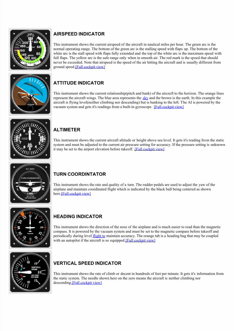
AIRSPEED INDICATOR
This instrument shows the current airspeed of the aircraft in nautical miles per hour. The green arc is thenormal operating range. The bottom of the green arc is the stalling speed with flaps up. The bottom of thewhite arc is the stall speed with flaps fully extended and the top of the white arc is the maximum speed with
full flaps. The yellow arc is the safe range only when in smooth air. The red mark is the speed that shouldnever be exceeded. Note that airspeed is the speed of the air hitting the aircraft and is usually different fromground speed .[Full cockpit view]
ATTITUDE INDICATOR
This instrument shows the current relationship(pitch and bank) of the aircraft to the horizon. The orange linesrepresent the aircraft wings. The blue area represents the sky and the brown is the earth. In this example theaircraft is flying level(neither climbing nor descending) but is banking to the left. The AI is powered by thevacuum system and gets it's readings from a built-in gyroscope. [Full cockpit view]
ALTIMETER
This instrument shows the current aircraft altitude or height above sea level. It gets it's reading from the staticsystem and must be adjusted to the current air pressure setting for accuracy. If the pressure setting is unknownit may be set to the airport elevation before takeoff. [Full cockpit view]
TURN COORDINTATOR
This instrument shows the rate and quality of a turn. The rudder pedals are used to adjust the yaw of theairplane and maintain coordinated flight which is indicated by the black ball being centered as shownhere .[Full cockpit view]
HEADING INDICATOR
This instrument shows the direction of the nose of the airplane and is much easier to read than the magnetic
compass. It is powered by the vacuum system and must be set to the magnetic compass before takeoff and periodically during level flight to maintain accuracy. The orange tab is a heading bug that may be coupledwith an autopilot if the aircraft is so equipped .[Full cockpit view]
VERTICAL SPEED INDICATOR
This instrument shows the rate of climb or decent in hundreds of feet per minute. It gets it's information fromthe static system. The needle shown here on the zero means the aircraft is neither climbing nordescending .[Full cockpit view]

8/13/2019 Cockpit Description
http://slidepdf.com/reader/full/cockpit-description 3/5
TACHOMETER
This instrument shows the revolutions per minute of the aircraft engine just as in an automobile, however thetachometer is much more important in flying. Many aspects of aircraft performance may be predicted at givenRPM settings. [Full cockpit view]
MAGNETIC COMPASS
This instrument is simply a wet magnetic compass. It has no external power source so it could be used in caseof other instrument failure. It is susceptible to turning and acceleration/deceleration errors while the aircraft ismoving.and therefore is not generally used in the real time navigation of the aircraft but as a reference to setthe heading indicator. [Full cockpit view]
VOR RECEIVER w/ GLIDESLOPE
This is a navigational instrument that can be tuned to ground-based electronic beacons called VORs(VeryHigh Frequency Omnidirectional Range) or to an ILS(Instrument Landing System) which allows a precisionapproach to a runway. The precision approach involves lining up both the vertical needle(localizer)andhorizontal needle(glideslope) on final approach to guide the aircraft down to the runway on the proper angle.The typical configuration in an aircraft includes two of these instruments, one with glideslope and onewithout. [Full cockpit view]
VOR RECEIVER
This is a navigational instrument that can be tuned to ground-based electronic beacons called VORs(VeryHigh Frequency Omnidirectional Range). It can also be tuned to an ILS(Instrument Landing System) howeverthis unit shows no glideslope information and therefore can be used for a "localizer only" approach. Thetypical configuration in an aircraft includes two VOR instruments, one with glideslope and one without. [Fullcockpit view]
AUTOMATIC DIRECTION FINDER
The ADF is a navigational instrument that can be tuned to ground-based electronic beacons called NonDirectional Beacons(NDB). Most NDBs are on or near airports. When tuned to a specific beacon, theADF needle always points toward that beacon. [Full cockpit view]
VACUUM GUAGE / AMMETER
The vacuum gauge show the pressure created by the vacuum pump which is needed to operate the AttitudeIndicator and Heading Indicator. The Ammeter indicates the quality of the alternator/charging system..Notethat these two items are often displayed with separate gauges depending on the model/year of theaircraft. [Full cockpit view]

8/13/2019 Cockpit Description
http://slidepdf.com/reader/full/cockpit-description 4/5
FUEL QUANTITY
Most small aircraft have two fuel tanks, one in each wing. This gauge indicates the level of fuel in each tank.Unlike an automobile, these gauges are used only as a cross-check. Pilots are trained to calculate their exact
fuel consumption before a flight and leave a reserve of at least 30 minutes for daytime and 45 minutes atnight .[Full cockpit view]
EXHAUST GAS TEMPERATURE / FUEL FLOW
To get proper performance from an aircraft, the fuel flow must be "leaned" at altitude to compensate for thedecrease in air density.This gauge helps the pilot lean the fuel for best efficiency. Note that some aircraft donot have this gauge and must be leaned by watching the Tachometer while slowly adjusting the mixturecontrol. [Full cockpit view]
OIL TEMPERATURE / PRESSURE GUAGE
This instrument monitors the temperature and pressure of circulating oil in the aircraft engine. [Full cockpitview]
AUDIO CONTROL PANEL This unit selects whichradios you are transmitting and/or receiving on. This unitshown also incorporates marker beacon lights(OMI) - Some donot .[Full cockpit view]
GPS or LORAN Some aircraft are equipped with aGPS(Global Positioning System) or LORAN(Long Range
Navigation System). GPS uses satellites and LORAN usesground based transmitters to calculate and display the aircraft'sexact position. [Full cockpit view]
NAV/COMM RADIO Actually two radios in one. The leftside is for voice communications with Air Traffic Control,other aircraft and listening to weather and airport information.The right side is for tuning in VORs & ILSs to be displayed onthe VOR instruments. This model has the flip-flop feature -you dial in a frequency in standby, the press then white<>
button to activate that frequency. [Full cockpit view]

8/13/2019 Cockpit Description
http://slidepdf.com/reader/full/cockpit-description 5/5
ADF (Automatic Direction Finder) Tunes in the NDBfrequency displayed on the ADF instrument. [Full cockpitview]
TRANSPONDER This unit sends a signal to the AirTraffic Control radar which displays your position and altitude.Aircraft that have not been assigned a 4 digit"squawk" code byATC should use 1200. [Full cockpit view]
DME (Distance Measuring Equipment) Some aircraft areequipped with DME which displays the distance to a specifiedVOR/DME beacon. [Full cockpit view]
HOBBS METER This is basically a timer which runswhen the aircraft engine is running. It is the equivalent of anodometer on an automobile. The Hobbs meter is how aircraftrental charges are calculated and maintenance schedules arekept. [Full cockpit view]
CLOCK/THERMOMETER Clock / Timer / Inside &outside temperature. [Full cockpit view]