A Vitreoretinal Surgery System Fluidics Failure Modes and ...
COBLATOR II Surgery System
COBLATOR™ IICOBLATION™ System
1 2 3 4 5 6 7 8 9
2000
1500
1000
500
0
Dep
th (m
m)
Ablation set point
COBLATION depth
Thermal margin
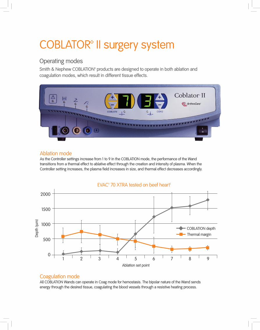
EVAC™ 70 XTRA tested on beef heart1
COBLATOR™ II surgery systemOperating modesSmith & Nephew COBLATION™ products are designed to operate in both ablation and coagulation modes, which result in different tissue effects.
Ablation mode As the Controller settings increase from 1 to 9 in the COBLATION mode, the performance of the Wand
transitions from a thermal effect to ablative effect through the creation and intensity of plasma. When the Controller setting increases, the plasma field increases in size, and thermal effect decreases accordingly.
Coagulation mode All COBLATION Wands can operate in Coag mode for hemostasis. The bipolar nature of the Wand sends
energy through the desired tissue, coagulating the blood vessels through a resistive heating process.

EC8000-01 COBLATOR II controller
ENTCARTPOLECOBLATION™ ENT system cart
EA 8002-00 Flow control unit
H 3000-03Shield foot control
H 3000-01Foot control
COBLATOR™ II parts

Connection diagram
* Refer to COBLATOR II user manual for detailed instructions
1 Controller2 Power cord3 Foot control4 Ablate pedal5 Coagulation pedal6 Coblate set point adjustment button7 Controller connector8 Handle9 Shaft10 Return electrode11 Active electrode tip12 Suction tube13 Irrigant tube14 Wand15 Flow control cable16 Flow control valve unit
6
5
3
4
16
15
10
11
14
12
13
Controller input power requirements Voltage 90-120 VAC
Frequency 50/60 Hz
RMS current 8 Amps Max
Fuse rating T8 Amps 250V for 120 VA
Output power Fundamental frequency 100 kHz
Voltage range 0-300 Vrms @ 100 kHz
Max output power 400 W @ 250 Ω
Operation temperature 10° C to 40° C
Controller dimensions Weight (max) <10 kg (22.4 lbs)
Height 13cm (5.25 inches)
Width 41cm (1.4 ft)
Length 45cm (1.45 ft)
Flow control valve unit dimensions Weight (max) 1 kg (2.2 lbs)
Height 8.9cm (3.5 inches)
Width 10.8cm (4.3 inches)
Length 22cm (8.7 inches)
Flow control cable Overall length 4.5 m (14.7 ft)
Part number EC8000-01
COBLATOR™ II system set-up*
COBLATOR II surgery system specifications
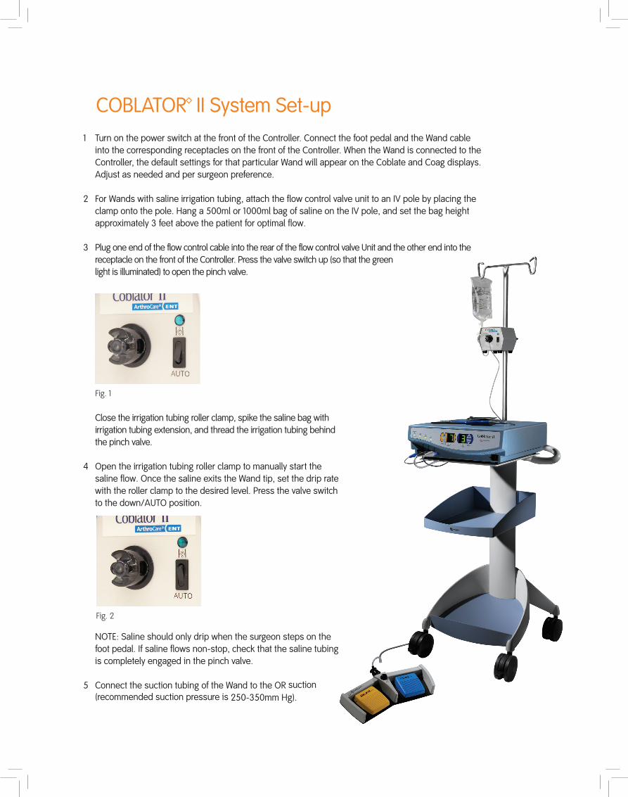
1 Turn on the power switch at the front of the Controller. Connect the foot pedal and the Wand cable into the corresponding receptacles on the front of the Controller. When the Wand is connected to the Controller, the default settings for that particular Wand will appear on the Coblate and Coag displays. Adjust as needed and per surgeon preference.
2 For Wands with saline irrigation tubing, attach the flow control valve unit to an IV pole by placing the clamp onto the pole. Hang a 500ml or 1000ml bag of saline on the IV pole, and set the bag height approximately 3 feet above the patient for optimal flow.
3 Plug one end of the flow control cable into the rear of the flow control valve Unit and the other end into the receptacle on the front of the Controller. Press the valve switch up (so that the green light is illuminated) to open the pinch valve.
Close the irrigation tubing roller clamp, spike the saline bag with irrigation tubing extension, and thread the irrigation tubing behind the pinch valve.
4 Open the irrigation tubing roller clamp to manually start the saline flow. Once the saline exits the Wand tip, set the drip rate with the roller clamp to the desired level. Press the valve switch to the down/AUTO position.
NOTE: Saline should only drip when the surgeon steps on the foot pedal. If saline flows non-stop, check that the saline tubing is completely engaged in the pinch valve.
5 Connect the suction tubing of the Wand to the OR suction (recommended suction pressure is 250-350mm Hg).
Fig. 1
Fig. 2
COBLATOR™ II System Set-up

ArthroCare Corporation7000 West William Cannon DriveAustin, TX 78735USA
www.smith-nephew.com
Information: 1-800-343-5717Orders/Inquiries: 1-888-994-2782
© 2015 Smith & Nephew, Inc. ™Trademark of Smith & Nephew. Reg. US Pat. & TM Office. P/N 58186 Rev. B 01/15
References1 Reference P/N 37785. Data on file at Smith & Nephew.