CoAP over DTLS TinyOS Implementation and …tesi.cab.unipd.it/44973/1/Thesis.pdfGiulio Peretti CoAP...
78
Giulio Peretti CoAP over DTLS TinyOS Implementation and Performance Analysis Implementazione di CoAP e DTLS in TinyOS ed Analisi delle Prestazioni Tesi di laurea magistrale Advisor: Prof. Michele Zorzi Co-Advisor: Vishwas Lakkundi, Ph.D. University of Padova School of Engineering Department of Information Engineering December 10, 2013
Transcript of CoAP over DTLS TinyOS Implementation and …tesi.cab.unipd.it/44973/1/Thesis.pdfGiulio Peretti CoAP...
Giulio Peretti
CoAP over DTLS TinyOS Implementation
and Performance Analysis
Implementazione di CoAP e DTLS in TinyOS ed Analisi delle Prestazioni
Tesi di laurea magistrale
Advisor: Prof. Michele ZorziCo-Advisor: Vishwas Lakkundi, Ph.D.
University of Padova
School of Engineering
Department of Information Engineering
December 10, 2013


Abstract
The IP-based Internet of Things (IoT) and the availability of inexpensive sensingdevices capable of wireless communications enable a wide range of applications suchas intelligent building automation and control, mobile health care, smart logisticsand distributed monitoring. IoT devices are expected to employ Constrained Appli-cation Protocol (CoAP) for the integration of such applications with the Internet,which suggests the use of Datagram Transport Layer Security (DTLS) protocolin order to provide authentication functionalities as well as essential end-to-endsecurity for the transmission of sensitive information.This thesis presents firstly an application called BlinkToSCoAP, obtained throughthe integration of three libraries implementing lightweight versions of DTLS andCoAP protocols as well as the IPv6/6LoWPAN stack. Secondly, an experimentalcampaign is presented that evaluates the performance of the DTLS security opera-tions. The experiments analyze the BlinkToSCoAP’s communications exchangedbetween two Zolertia Z1 devices, allowing evaluations in terms of memory footprint,energy consumption, latency and packet overhead. Based on performance analysisresults and the experience gained during the implementation phase, this thesisfinally presents an outlook on future works that can be developed in order toenhance the application performance.
iii
Sommario
La tecnologia Internet-of-Things (IoT), basata sul protocollo IP, e la disponibili-tà di dispositivi economici dotati di sensori e funzionalità wireless sono alla basedi un’ampia gamma di applicazioni come il controllo intelligente ed automatico diedifici, la supervisione delle funzioni vitali in ambito medico ed il monitoraggiodistribuito. I dispositivi IoT implementano il Constrained Application Protocol(CoAP) per integrare tali applicazioni con Internet. Lo standard di tale protocolloconsiglia l’utilizzo del protocollo Datagram Transport Layer Security (DTLS) pergarantire le essenziali funzionalità di sicurezza end-to-end per trasmissioni di datisensibili e per autenticare i dispositivi coinvolti nella comunicazione.La tesi presenta un’applicazione che integra i protocolli DTLS, CoAP e lo stackIPv6/6LoWPAN, basata su implementazioni sviluppate dal SIGNET Group delDipartimento di Ingegneria dell’Informazione di Padova. In secondo luogo vienepresentata una serie di esperimenti con lo scopo di valutare la variazione di perfor-mance dovuta alle operazioni di sicurezza del protocollo DTLS. Tale variazione saràvalutata in termini di memoria ed energia richiesta, ritardi e overhead nei pacchetti.Basandosi sui risultati degli esperimenti effettuati e sull’esperienza guadagnatadurante la fase di sviluppo dell’applicazione, la tesi presenta infine una serie disuggerimenti per eventuali lavori futuri che estendono il lavoro presentato.
iv
Acknowledgements
Desidero ringraziare tutti coloro che mi hanno aiutato nella realizzazione diquesta mia Tesi. Ringrazio la mia famiglia per il quotidiano sostegno morale, perla fiducia riposta nelle mie capacità. Ringrazio Michele Zorzi e Vishwas Lakkundiper il supporto fornito, ringrazio Giulio Marin per avermi aiutato nella revisionedella lingua inglese e per i suoi preziosi consigli. Ringrazio inoltre Moreno Dissegnae Matteo Fiorindo per il supporto fornito nella progettazione e valutazione degliesperimenti effettuati, Mario Emilio Cecconato per il suo sostegno prima e durantela stesura del codice dell’applicazione sviluppata. Ringrazio infine tutte le personeche mi sono state vicino in questi mesi impegnativi, le persone che mi hanno fattosorridere, le persone che non hanno mai smesso di spronarmi ed avere fiducia in me.
Padova, December 10, 2013 Giulio
v

Contents
1 Introduction 11.1 Motivation . . . . . . . . . . . . . . . . . . . . . . . . . . . . . . . . 11.2 Contribution . . . . . . . . . . . . . . . . . . . . . . . . . . . . . . . 21.3 Related Work . . . . . . . . . . . . . . . . . . . . . . . . . . . . . . 31.4 Outline . . . . . . . . . . . . . . . . . . . . . . . . . . . . . . . . . . 4
2 Constrained Application Protocol 52.1 CoAP Overview . . . . . . . . . . . . . . . . . . . . . . . . . . . . . 5
2.1.1 CoAP Requests and Responses . . . . . . . . . . . . . . . . 72.1.2 Messages . . . . . . . . . . . . . . . . . . . . . . . . . . . . . 8
2.2 Message Format . . . . . . . . . . . . . . . . . . . . . . . . . . . . . 9
3 Datagram Transport Layer Security 133.1 TLS Overview . . . . . . . . . . . . . . . . . . . . . . . . . . . . . . 13
3.1.1 TLS Handshake Protocol . . . . . . . . . . . . . . . . . . . . 143.1.2 TLS ChangeCipherSpec, Alert and Application Protocol . . 163.1.3 TLS Record Protocol . . . . . . . . . . . . . . . . . . . . . . 17
3.2 DTLS Overview . . . . . . . . . . . . . . . . . . . . . . . . . . . . . 183.2.1 DTLS Handshake Protocol . . . . . . . . . . . . . . . . . . . 183.2.2 DTLS Record Protocol . . . . . . . . . . . . . . . . . . . . . 19
4 Environment Set-up 214.1 Zolertia Z1 Module . . . . . . . . . . . . . . . . . . . . . . . . . . . 214.2 TinyOS and NesC . . . . . . . . . . . . . . . . . . . . . . . . . . . . 22
4.2.1 TinyOS Executive Model . . . . . . . . . . . . . . . . . . . . 234.2.2 NesC Programming Language . . . . . . . . . . . . . . . . . 23
4.3 System Set-up . . . . . . . . . . . . . . . . . . . . . . . . . . . . . . 24
5 BlinkToSCoAP Implementation 275.1 Protocol Libraries . . . . . . . . . . . . . . . . . . . . . . . . . . . . 27
vii
viii CONTENTS
5.1.1 CoAP Protocol Library . . . . . . . . . . . . . . . . . . . . . 275.1.2 DTLS Protocol Library . . . . . . . . . . . . . . . . . . . . . 285.1.3 IPv6/6LoWPAN Protocol Stack Library . . . . . . . . . . . 30
5.2 BlinkToSCoAP Application . . . . . . . . . . . . . . . . . . . . . . 325.2.1 BTSCTest Component and Wiring . . . . . . . . . . . . . . 325.2.2 CoAP Wiring . . . . . . . . . . . . . . . . . . . . . . . . . . 335.2.3 SSLP Component and DTLS, SiGLoWPAN Wiring . . . . . 375.2.4 Practical Issues . . . . . . . . . . . . . . . . . . . . . . . . . 42
5.3 BlinkToCoAP . . . . . . . . . . . . . . . . . . . . . . . . . . . . . . 43
6 Performance Analysis and Results 456.1 Memory Footprint . . . . . . . . . . . . . . . . . . . . . . . . . . . 456.2 Packet Overhead . . . . . . . . . . . . . . . . . . . . . . . . . . . . 466.3 Energy Consumption . . . . . . . . . . . . . . . . . . . . . . . . . . 49
7 Conclusions 637.1 Concluding Remarks . . . . . . . . . . . . . . . . . . . . . . . . . . 637.2 Future Work . . . . . . . . . . . . . . . . . . . . . . . . . . . . . . . 64
Bibliography 67
List of Figures
2.1 The CoRE ReSTful architecture. . . . . . . . . . . . . . . . . . . . 62.2 CoAP protocol layers. . . . . . . . . . . . . . . . . . . . . . . . . . 72.3 Client-server model. . . . . . . . . . . . . . . . . . . . . . . . . . . . 72.4 Piggy-backed and separated responses in CoAP. . . . . . . . . . . . 102.5 CoAP message format. . . . . . . . . . . . . . . . . . . . . . . . . . 11
3.1 TLS protocol stack. . . . . . . . . . . . . . . . . . . . . . . . . . . . 133.2 TLS handshake. . . . . . . . . . . . . . . . . . . . . . . . . . . . . . 143.3 TLS record protocol operations. . . . . . . . . . . . . . . . . . . . . 173.4 DTLS handshake retransmission state machine. . . . . . . . . . . . 193.5 DTLS handshake with cookie exchange. . . . . . . . . . . . . . . . . 20
4.1 Zolertia Z1 module. . . . . . . . . . . . . . . . . . . . . . . . . . . . 224.2 BlinkC wiring example. . . . . . . . . . . . . . . . . . . . . . . . . . 25
5.1 CoAP library structure. . . . . . . . . . . . . . . . . . . . . . . . . 285.2 DTLS library structure. . . . . . . . . . . . . . . . . . . . . . . . . 295.3 SiGLoWPAN architecture. . . . . . . . . . . . . . . . . . . . . . . . 315.4 BlinkToSCoAP architecture. . . . . . . . . . . . . . . . . . . . . . . 325.5 BTSCTest wiring. . . . . . . . . . . . . . . . . . . . . . . . . . . . . 335.6 CoAPClient interface. . . . . . . . . . . . . . . . . . . . . . . . . . 345.7 CoAPServer interface. . . . . . . . . . . . . . . . . . . . . . . . . . 355.8 UDP6LPClient interface. . . . . . . . . . . . . . . . . . . . . . . . . 365.9 SSLP wiring . . . . . . . . . . . . . . . . . . . . . . . . . . . . . . . 385.10 DTLS interface. . . . . . . . . . . . . . . . . . . . . . . . . . . . . . 395.11 UDP interface. . . . . . . . . . . . . . . . . . . . . . . . . . . . . . 405.12 Memory interface. . . . . . . . . . . . . . . . . . . . . . . . . . . . . 415.13 BlinkToCoAP Architecture. . . . . . . . . . . . . . . . . . . . . . . 44
6.1 DTLS RAM memory overhead. . . . . . . . . . . . . . . . . . . . . 466.2 DTLS ROM memory overhead. . . . . . . . . . . . . . . . . . . . . 47
ix
x LIST OF FIGURES
6.3 DTLS overhead expressed in bytes. . . . . . . . . . . . . . . . . . . 486.4 Electrical schematic for energy measurement. . . . . . . . . . . . . . 496.5 Energy experiment electrical schematic with AVR. . . . . . . . . . . 516.6 Client secured transmission and LED activity. . . . . . . . . . . . . 536.7 Server secured transmission and LED activity. . . . . . . . . . . . . 536.8 Client secured transmission. . . . . . . . . . . . . . . . . . . . . . . 546.9 Server secured transmission. . . . . . . . . . . . . . . . . . . . . . . 556.10 Client unsecured transmission. . . . . . . . . . . . . . . . . . . . . . 556.11 Server unsecured transmission. . . . . . . . . . . . . . . . . . . . . . 566.12 Comparison of energy consumption. . . . . . . . . . . . . . . . . . . 586.13 Energy consumption of DTLS and SSLP components for a secured
CoAP transaction. . . . . . . . . . . . . . . . . . . . . . . . . . . . 596.14 Client handshake phase. . . . . . . . . . . . . . . . . . . . . . . . . 606.15 Server handshake phase. . . . . . . . . . . . . . . . . . . . . . . . . 60
Chapter 1
Introduction
1.1 Motivation
The paradigm Internet of Things (IoT) denotes the Internet-like interconnectionof highly heterogeneous and wireless-capable entities such as sensors, actuators andmobile devices, in a Low power and Lossy Network (LLN). These small devicesusually have 8-bit microcontrollers with small amounts of ROM and RAM, whileconstrained networks usually have high packet error rates and very low throughputs.Proposed for the first time by Kevin Ashton in 2009 [9], the IoT allows a widerange of application scenarios with potentially critical actuating and sensing tasks.The integration of such applications with the Internet will contribute to shape avision of a future Web that is nowadays denoted as the Web of Things (WoT). Inthis scenario, IoT entities interact with each other, with Internet remote servicesand with humans carrying an Internet-capable device, like a smartphone.
In order to simplify this integration, the fundamental building blocks used forIoT applications are the web services, the IPv6 protocol and its LLN compressedversion obtained through the IPv6 Low power Wireless Personal Area Network(6LoWPAN) protocol. More specifically, the 6LoWPAN protocol defines encapsula-tion and header compression mechanisms that allow IPv6 packets to be efficientlysent over constrained networks. The Internet Engineering Task Force ConstrainedRestful Environments (IETF CoRE) working group provides a framework for IoTresource-oriented applications with the standardization of the Constrained Appli-cation Protocol (CoAP), that is a LLN optimized version of the HTTP protocoldesigned to run over the UDP protocol, in order to guarantee efficient communica-tions at the application level.
1
2 CHAPTER 1. INTRODUCTION
The standardization of the CoAP protocol suggests the introduction of trans-mission security. The most common approach to provide security functionalitiesto the Internet communications is given by the Transport Layer Security (TLS)protocol, together with a public-key infrastructure. Unfortunately, TLS is notsuited to constrained networks as it needs reliable channels and due to high powerconsumption. For this reason, multiple alternatives have been proposed to solvethe security requirements in constrained environments. Therefore, in order toprotect the transmission of information, the CoAP standard [16] allows either theusage of Datagram Transport Layer Security (DTLS) or Internet Protocol Security(IPsec), which are end-to-end security approaches that achieve replay protection,data integrity and authentication.
IPsec is a network layer protocol and is implemented in the kernel of operatingsystems. For this reason, it may not be the best choice for all kinds of environments[2]. IPsec is not supported by all the embedded IP stacks and neither by all PCoperating systems or back-end web servers. In addition, application developers maynot have privileges to add a security gateway to the network or to enable and con-figure IPsec. Firewalls and NATs might thus compromise the usage of this approach.
A more suitable solution is currently represented by a datagram capable versionof TLS, the DTLS protocol. A great advantage of DTLS over IPsec is that it isan application layer protocol, thus implemented in the application space insteadof in the kernel, therefore avoiding the aforementioned problems for the IPsecprotocol. In addiction, thanks to their similarity, DTLS allows the reusage of ex-isting TLS protocol infrastructure at the cost of a minimal application overhead [15].
1.2 Contribution
This thesis presents an IoT application that includes the CoAP protocol, pro-tected by the DTLS protocol, running over the IPv6/6LowPAN stack. It is realizedby merging, adapting and optimizing previously existing implementations of theseprotocols, all written by different authors within the Department of InformationEngineering (DEI) at the University of Padova. Furthermore, it gives an in-depthanalysis of the performance variation due to the presence of the security protocolincluding:
• additional RAM and ROM memory usage of the application, since data

1.3. RELATED WORK 3
storage and especially RAM are very critical resources on actual sensor nodeplatforms
• computational time and energy overhead required, as they represent twoimportant evaluation criteria of the feasibility of the security implementation
• packet length overhead introduced by the DTLS header.
1.3 Related Work
Recently, a lot of research into end-to-end security protocols for the IoT andWSNs running CoAP has been conducted.
Authors of [10] introduce a DTLS security architecture that performs two-wayauthentication, which includes both client and server authentication, based on RSA,the most widespread key exchange algorithm. This particular asymmetric encryp-tion algorithm requires too much resources in constrained devices, furthermore thedevices considered in that architecture have to guarantee hardware support forsecure application and RSA key storage, such as Trusted Platform Modules (TPMs).This architecture, running over the 6LowPAN protocol, achieves proper authentica-tion through the access control server, a trusted non-constrained entity in which theaccess rights of the sensor device are stored, and through X.509 certificates signed bya trusted third party, called Certificate Authority. The architecture has been thentested in terms of latency and energy consumption in order to evaluate its feasibility.
In [6] the performance impact of several DTLS security modes, proposed by theCoAP standard, is analyzed in order to identify the limitations of node platformsand the requirements of IoT applications. The authors have evaluated the energy,the packet and the computational overhead as well as the memory footprint of thevarious security modes, showing that the small memory space and the absence ofElliptic Curve Cryptography (ECC) hardware support are a critical aspect for thecompatibility of the IoT networks with existing public-key certification infrastruc-tures. However, some DTLS security suites were identified as viable if security andresources usage compromises are allowed by the network application.
In [7] an extensive experimental evaluation is presented to identify the mostappropriate secure communications mechanisms between end-to-end network-layerand application-layer security, compared in terms of energy, computational over-heads and memory footprints. The authors have described the impact of end-to-end
4 CHAPTER 1. INTRODUCTION
security on communications rate of sensing devices as well as on the lifetime of theconstrained network. The end-to-end approach provides the benefit of enabling se-cure communications regardless of the application, while the network-layer securitymay facilitate the integration with certification infrastructures through the usageof ECC, at the cost of more resources.
In [13], it has been shown that DTLS headers can be compressed using 6LoWPANmechanisms, significantly reducing the number of additional security bits. Thisresult leads to an increment of both the network lifetime and the achievablethroughput. The same authors, in a more recent work [14], have presented Lithe, aDTLS secured CoAP implementation that exploits the data compression methodsmentioned earlier.
1.4 Outline
After introducing the Constrained Application Protocol (CoAP) and the Data-gram Transport Layer Security (DTLS), the thesis presents the environment set-upused to develop and test the BlinkToSCoAP application, described in Chapter 5.The following Chapter 6 presents the experiment campaign together with the re-sults achieved, while the last Chapter 7 draws the conclusions and reports somesuggestions for future work.
Chapter 2
Constrained Application Protocol
2.1 CoAP Overview
The Constrained Application Protocol (CoAP) is a specialized web transferprotocol intended to be used by constrained devices in Machine-to-Machine (M2M)applications. M2M can be seen as a subset of IoT, as it refers to all the technologiesthat allow machines to communicate with each other, especially over Internet pro-tocols in wireless channels. The CoAP protocol provides a client/server interactionmodel between application endpoints and includes the same key functionalities ofthe HTTP protocol. For this reason CoAP is easily interfaced with HTTP, resultingin simplified web integration while also ensuring M2M critical requirements such aslow overhead, multicast support, built-in discovery and simplicity.
The Representational State Transfer (ReST), named for the first time by RoyThomas Fielding in his Ph.D. dissertation [5], is a network architectural stylethat abstracts the implementation of the network elements within a distributedhypermedia system1. Moreover, ReST focuses on the architectural elements role,the constraints in their interactions and interpretation as significant data elements.
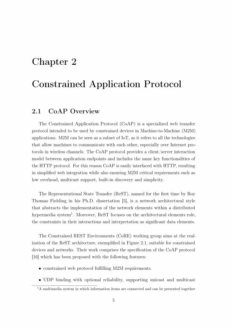
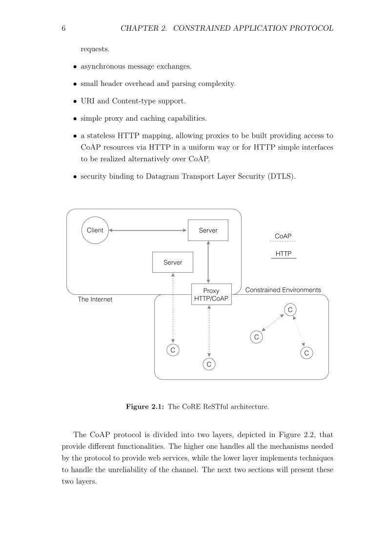
The Constrained REST Environments (CoRE) working group aims at the real-ization of the ReST architecture, exemplified in Figure 2.1, suitable for constraineddevices and networks. Their work comprises the specification of the CoAP protocol[16] which has been proposed with the following features:
• constrained web protocol fulfilling M2M requirements.
• UDP binding with optional reliability, supporting unicast and multicast
1A multimedia system in which information items are connected and can be presented together
5
6 CHAPTER 2. CONSTRAINED APPLICATION PROTOCOL
requests.
• asynchronous message exchanges.
• small header overhead and parsing complexity.
• URI and Content-type support.
• simple proxy and caching capabilities.
• a stateless HTTP mapping, allowing proxies to be built providing access toCoAP resources via HTTP in a uniform way or for HTTP simple interfacesto be realized alternatively over CoAP.
• security binding to Datagram Transport Layer Security (DTLS).
The InternetConstrained EnvironmentsProxy
HTTP/CoAP
C
C
C
CC
Client Server
Server
CoAP
HTTP
Figure 2.1: The CoRE ReSTful architecture.
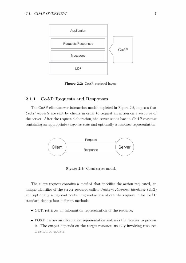
The CoAP protocol is divided into two layers, depicted in Figure 2.2, thatprovide different functionalities. The higher one handles all the mechanisms neededby the protocol to provide web services, while the lower layer implements techniquesto handle the unreliability of the channel. The next two sections will present thesetwo layers.
2.1. COAP OVERVIEW 7
UDP
Requests/Responses
Messages
CoAP
Application
Figure 2.2: CoAP protocol layers.
2.1.1 CoAP Requests and Responses
The CoAP client/server interaction model, depicted in Figure 2.3, imposes thatCoAP requests are sent by clients in order to request an action on a resource ofthe server. After the request elaboration, the server sends back a CoAP responsecontaining an appropriate response code and optionally a resource representation.
Client Server
Request
Response
Figure 2.3: Client-server model.
The client request contains a method that specifies the action requested, anunique identifier of the server resource called Uniform Resource Identifier (URI)and optionally a payload containing meta-data about the request. The CoAPstandard defines four different methods:
• GET: retrieves an information representation of the resource.
• POST: carries an information representation and asks the receiver to processit. The output depends on the target resource, usually involving resourcecreation or update.
8 CHAPTER 2. CONSTRAINED APPLICATION PROTOCOL
• PUT: requests an update operation of the resource identified by the requestURI with the carried information representation.
• DELETE: causes the deletion of the resource identified by the request URI.
Upon reception of the request, the server elaborates it and, if no errors occur, sendsback to the client its response containing a response code that indicates the resultof the request process. Response codes are divided into three classes:
• 2.xx (Success): the request has successfully been received and processed.
• 4.xx (Client Error): the request was not valid or correctly understood by theserver.
• 5.xx (Server Error): the server accepted the request but failed to process it.
The fraction of the response code just denoted with xx does not have any catego-rization role: it gives instead additional details of the output of the request process.For example, the most common HTTP response code is the 404 or not found error,which indicates that the client request was correct but the server was not able tofind the resource pointed by the URI field.
The matching between requests and responses is achieved by means of a token,that is an unique identifier of any request/response couple between two specificendpoints. This field is included on every CoAP request as well as in every CoAPresponse.
2.1.2 Messages
As CoAP is by default bound to UDP, requests and responses can appearduplicated, arrive out of order or go missing. To deal with this issue, the protocolis theoretically divided into two logical layers, where the upper one comprises therequest/response mechanisms previously introduced and the lower one handles alightweight reliability mechanism.
The message layer is totally independent of the request/response layer. It definesfour message types:
• Confirmable (CON): indicates that the carried data have to be acknowledgedfrom the receiver, providing reliability functionality.
• Non Confirmable (NON): carries data that do not require acknowledgmentsbut still has to be protected from message duplication.
2.2. MESSAGE FORMAT 9
• Acknowledgement (ACK): acknowledges CON messages.
• Reset (RST): signals errors occurred in the reception of a CON or NONmessage.
The matching of CON/ACK messages and the message duplicate detection is doneby means of a Message ID, generated and enclosed in every CON and NON message.As for the token introduced in the previous section, the Message ID has to beunique for every NON or CON/ACK message between two specific endpoints. Untilthe reception of the matched ACK message from the same destination, the CONmessage is retransmitted through the channel using a default timeout with anexponential back-off time.
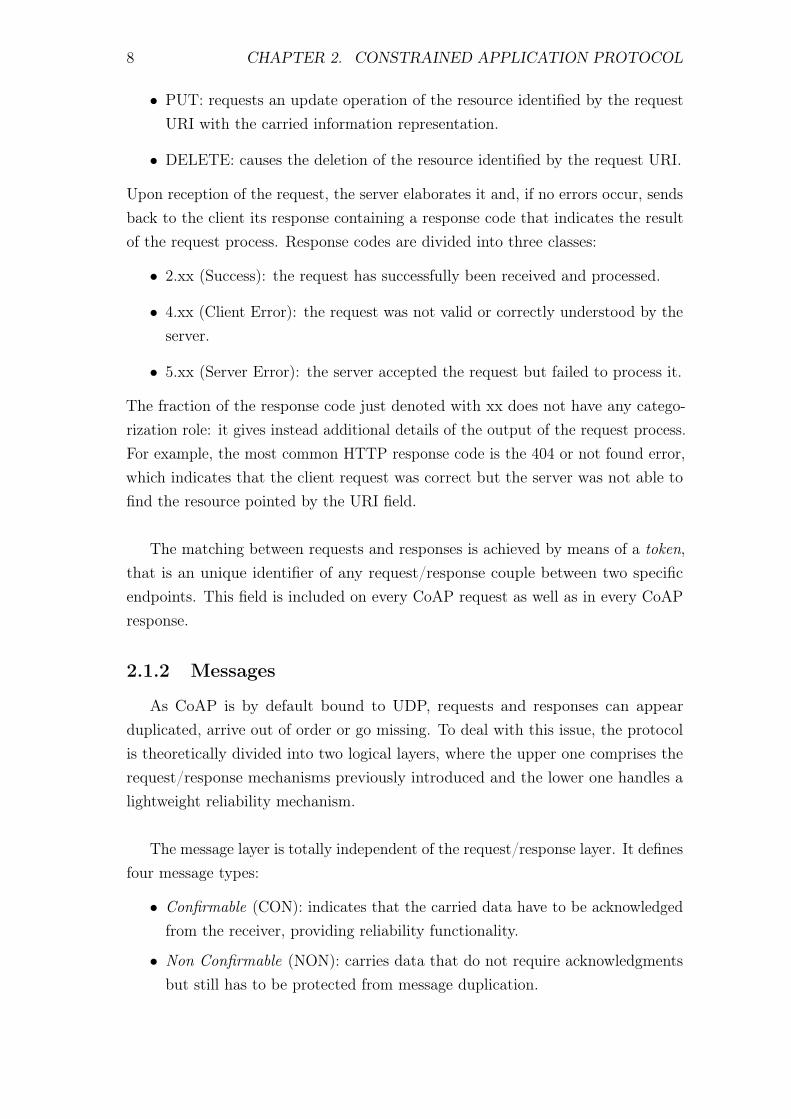
These message types can embody client requests or server responses as shown inTable 2.1. The special combination of a Confirmable message without any requestor response included is used only to trigger a Reset message, realizing the CoAPping application.
CON NON ACK RST
Request X X - -Response X X X -Empty * - X X
Table 2.1: Usage of message types.
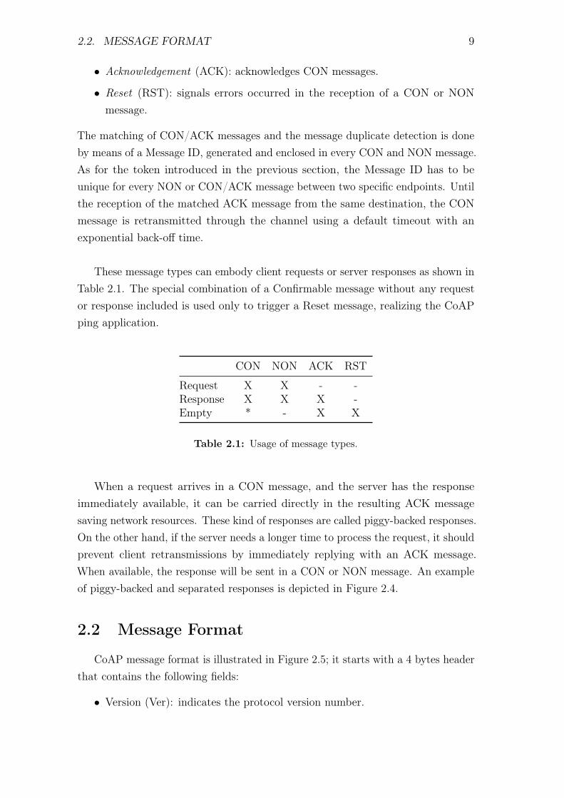
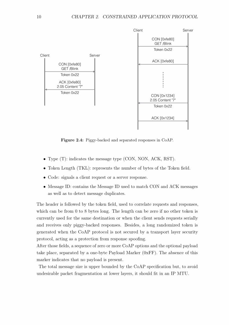
When a request arrives in a CON message, and the server has the responseimmediately available, it can be carried directly in the resulting ACK messagesaving network resources. These kind of responses are called piggy-backed responses.On the other hand, if the server needs a longer time to process the request, it shouldprevent client retransmissions by immediately replying with an ACK message.When available, the response will be sent in a CON or NON message. An exampleof piggy-backed and separated responses is depicted in Figure 2.4.
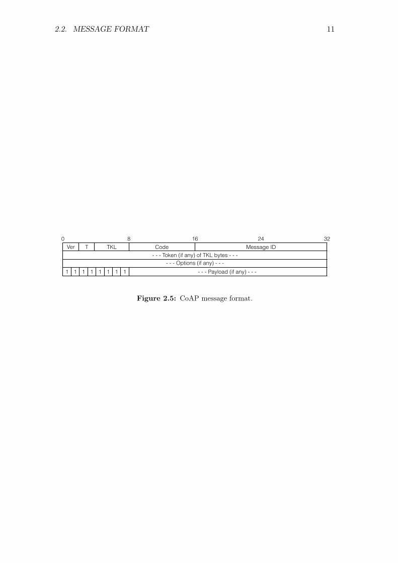
2.2 Message Format
CoAP message format is illustrated in Figure 2.5; it starts with a 4 bytes headerthat contains the following fields:
• Version (Ver): indicates the protocol version number.
10 CHAPTER 2. CONSTRAINED APPLICATION PROTOCOL
CON [0xfe80] GET /BlinkToken 0x22
ACK [0xfe80] 2.05 Content "7"
Token 0x22
Client Server
CON [0xfe80] GET /BlinkToken 0x22
ACK [0xfe80]
Client Server
CON [0x1234] 2.05 Content "7"
Token 0x22
ACK [0x1234]
Figure 2.4: Piggy-backed and separated responses in CoAP.
• Type (T): indicates the message type (CON, NON, ACK, RST).
• Token Length (TKL): represents the number of bytes of the Token field.
• Code: signals a client request or a server response.
• Message ID: contains the Message ID used to match CON and ACK messagesas well as to detect message duplicates.
The header is followed by the token field, used to correlate requests and responses,which can be from 0 to 8 bytes long. The length can be zero if no other token iscurrently used for the same destination or when the client sends requests seriallyand receives only piggy-backed responses. Besides, a long randomized token isgenerated when the CoAP protocol is not secured by a transport layer securityprotocol, acting as a protection from response spoofing.After those fields, a sequence of zero or more CoAP options and the optional payloadtake place, separated by a one-byte Payload Marker (0xFF). The absence of thismarker indicates that no payload is present.The total message size is upper bounded by the CoAP specification but, to avoidundesirable packet fragmentation at lower layers, it should fit in an IP MTU.
2.2. MESSAGE FORMAT 11
8 16 24Ver T TKL Code Message ID
- - - Token (if any) of TKL bytes - - -- - - Options (if any) - - -
1 1 1 1 1 1 1 1 - - - Payload (if any) - - -
0 32
Figure 2.5: CoAP message format.

Chapter 3
Datagram Transport Layer Security
Datagram Transport Layer Security (DTLS), defined in [15], is an extension ofthe Transport Layer Security (TLS) protocol. This chapter introduces TLS andthen describes the main modifications accomplished in DTLS in order to adapt itto unreliable transport protocols.
3.1 TLS Overview
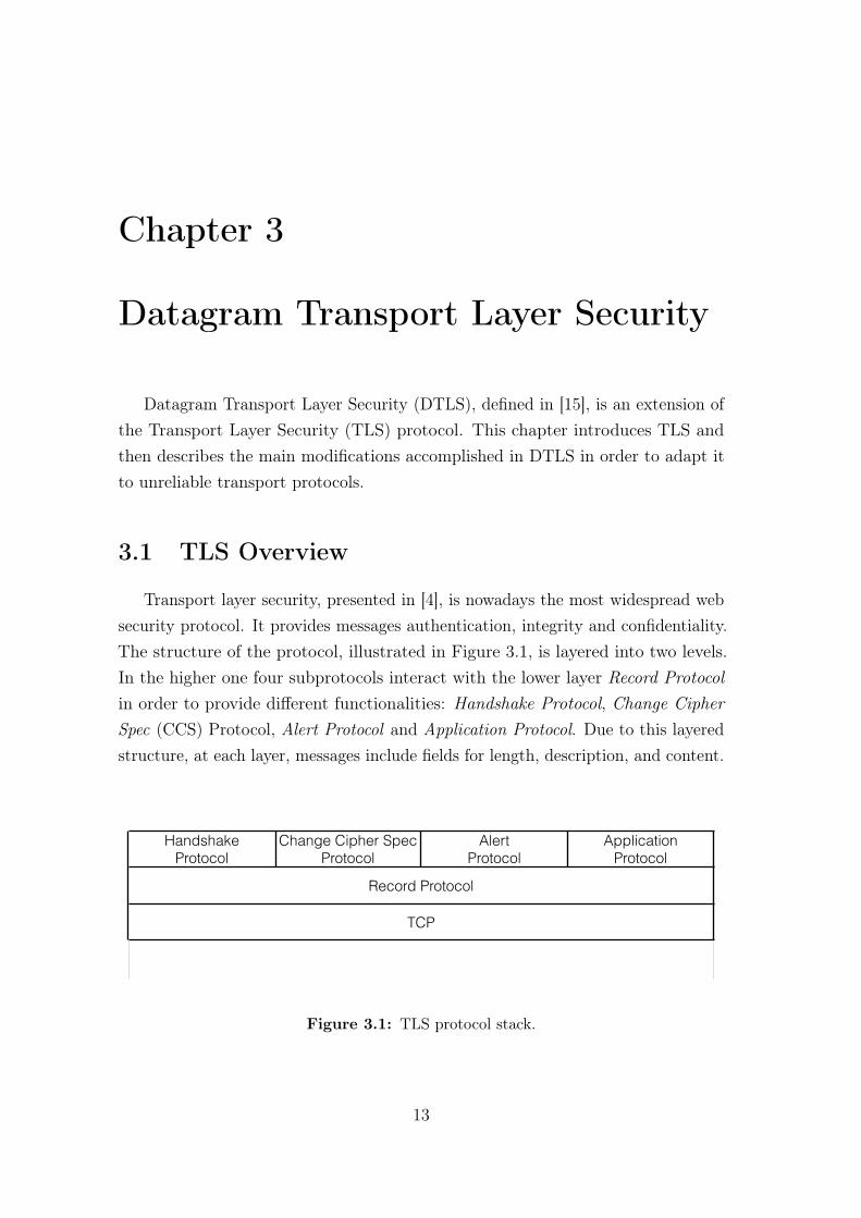
Transport layer security, presented in [4], is nowadays the most widespread websecurity protocol. It provides messages authentication, integrity and confidentiality.The structure of the protocol, illustrated in Figure 3.1, is layered into two levels.In the higher one four subprotocols interact with the lower layer Record Protocolin order to provide different functionalities: Handshake Protocol, Change CipherSpec (CCS) Protocol, Alert Protocol and Application Protocol. Due to this layeredstructure, at each layer, messages include fields for length, description, and content.
Handshake Protocol
Change Cipher Spec Protocol
Alert Protocol
Application Protocol
Record Protocol
TCP
Figure 3.1: TLS protocol stack.
13
14 CHAPTER 3. DATAGRAM TRANSPORT LAYER SECURITY
3.1.1 TLS Handshake Protocol
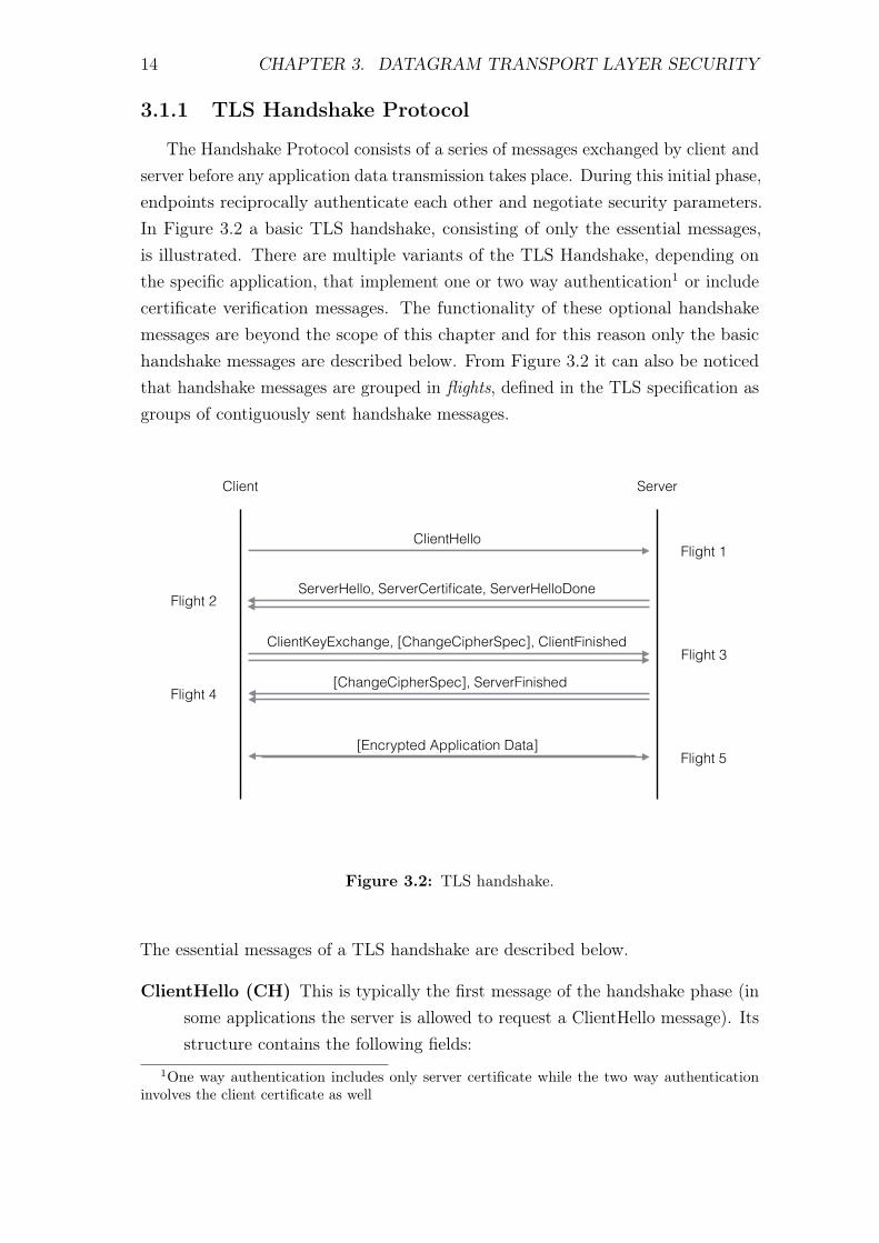
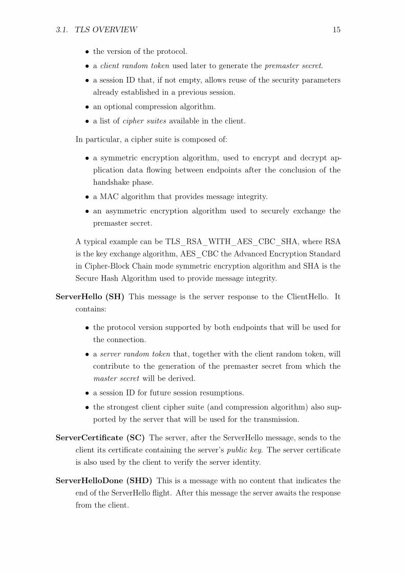
The Handshake Protocol consists of a series of messages exchanged by client andserver before any application data transmission takes place. During this initial phase,endpoints reciprocally authenticate each other and negotiate security parameters.In Figure 3.2 a basic TLS handshake, consisting of only the essential messages,is illustrated. There are multiple variants of the TLS Handshake, depending onthe specific application, that implement one or two way authentication1 or includecertificate verification messages. The functionality of these optional handshakemessages are beyond the scope of this chapter and for this reason only the basichandshake messages are described below. From Figure 3.2 it can also be noticedthat handshake messages are grouped in flights, defined in the TLS specification asgroups of contiguously sent handshake messages.
Client Server
ClientHello
ServerHello, ServerCertificate, ServerHelloDone
[ChangeCipherSpec], ServerFinished
[Encrypted Application Data]
ClientKeyExchange, [ChangeCipherSpec], ClientFinished
Flight 1
Flight 3
Flight 5
Flight 2
Flight 4
Figure 3.2: TLS handshake.
The essential messages of a TLS handshake are described below.
ClientHello (CH) This is typically the first message of the handshake phase (insome applications the server is allowed to request a ClientHello message). Itsstructure contains the following fields:
1One way authentication includes only server certificate while the two way authenticationinvolves the client certificate as well
3.1. TLS OVERVIEW 15
• the version of the protocol.
• a client random token used later to generate the premaster secret.
• a session ID that, if not empty, allows reuse of the security parametersalready established in a previous session.
• an optional compression algorithm.
• a list of cipher suites available in the client.
In particular, a cipher suite is composed of:
• a symmetric encryption algorithm, used to encrypt and decrypt ap-plication data flowing between endpoints after the conclusion of thehandshake phase.
• a MAC algorithm that provides message integrity.
• an asymmetric encryption algorithm used to securely exchange thepremaster secret.
A typical example can be TLS_RSA_WITH_AES_CBC_SHA, where RSAis the key exchange algorithm, AES_CBC the Advanced Encryption Standardin Cipher-Block Chain mode symmetric encryption algorithm and SHA is theSecure Hash Algorithm used to provide message integrity.
ServerHello (SH) This message is the server response to the ClientHello. Itcontains:
• the protocol version supported by both endpoints that will be used forthe connection.
• a server random token that, together with the client random token, willcontribute to the generation of the premaster secret from which themaster secret will be derived.
• a session ID for future session resumptions.
• the strongest client cipher suite (and compression algorithm) also sup-ported by the server that will be used for the transmission.
ServerCertificate (SC) The server, after the ServerHello message, sends to theclient its certificate containing the server’s public key. The server certificateis also used by the client to verify the server identity.
ServerHelloDone (SHD) This is a message with no content that indicates theend of the ServerHello flight. After this message the server awaits the responsefrom the client.
16 CHAPTER 3. DATAGRAM TRANSPORT LAYER SECURITY
ClientKeyExchange (CKE) This message is sent after computing the premastersecret using both the client and server random tokens. The premaster secretis then enclosed in the ClientKeyExchange message after being encryptedthrough the chosen key exchange algorithm using the server public key. Bothendpoints will use this parameter in order to locally compute the master secret,that will be extended through the PRF function2 into several keys intendedto be used for the encryption and HMAC algorithms. ClientKeyExchangemessage also includes the client protocol version in order to guard againstrollback attacks, which cause the server and the client to use an earlier andthus less secure version of the protocol.
ChangeCipherSpec (CCS) notifies to the other endpoint that all future mes-sages will be encrypted using the keys and algorithms just negotiated. TheChangeCipherSpec message is not really part of the Handshake Protocol as itbelongs to the ChangeCipherSpec Protocol.
ClientFinished (CF) This message is the first message being encrypted andhashed by the record layer, and signals that the client has no other handshakemessages to send. It contains also a hash of the entire conversation in orderto provide further authentication of the client.
ServerFinished (SF) Like the CF message just described, this message is a hashof the entire handshake exchange until this point. If the client is able tosuccessfully decrypt this message and the contained data, the TLS handshakeis successful and the two endpoints are ready to exchange application data ina secure manner.
3.1.2 TLS ChangeCipherSpec, Alert and Application Proto-
col
The CCS Protocol is composed only by the ChangeCipherSpec message describedabove. This protocol has the purpose of allowing developers to define their ownCCS mechanisms.Messages belonging to the Alert Protocol convey TLS alerts carrying informationabout errors occurred. Alert messages are divided into two levels, warning andfatal. Fatal alerts result in the immediate termination of the session, forcing theestablishment of a new connection in order to keep the transmissions safe. Ifotherwise a waring alert is sent or received, the connection can continue normally
2A mechanism used to produce a securely generated pseudo-random output of arbitrary length.
3.1. TLS OVERVIEW 17
or be terminated depending on the specific situation. The Application Protocolrefers to the higher level protocol that utilizes the DTLS protocol services.
3.1.3 TLS Record Protocol
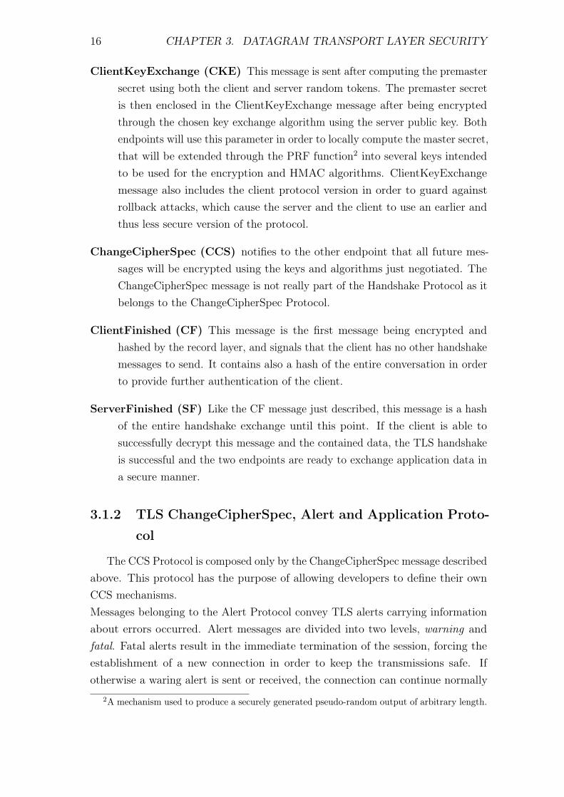
The last portion of the TLS protocol, at the bottom of its structure, is the TLSRecord Layer which applies security mechanisms and handles data transport. Asillustrated in Figure 3.3, this protocol merges and fragments messages coming fromthe upper protocols into more manageable blocks. If possible, multiple messages ofthe same type can be enclosed together into a single record, or a single long one canbe fragmented across several records. Moreover the TLS Record Protocol optionallycompresses the data, adds a MAC field, encrypts and finally transmits the resultingextended fragment. When a new packet is delivered to Record Protocol from lowerlayers, the data is decrypted, verified, decompressed, reassembled and then passedon to higher layer protocols.
Application data
Fragment
Compress
Add MAC
Encrypt
Append TSL record header
Figure 3.3: TLS record protocol operations.
The TLS protocol is assumed to be interfaced with a reliable transport protocolsuch as TCP. This requirement prohibits its utilization in LLN networks, whereunreliable transport protocols are a more efficient choice. For this reason, as
18 CHAPTER 3. DATAGRAM TRANSPORT LAYER SECURITY
mentioned in Chapter 2, the CoAP specification suggests to secure communicationsby means of the DTLS protocol.
3.2 DTLS Overview
Datagram Transport Layer Security is a modified version of TLS that resolvesthe original protocol issues when running over unreliable transport protocols. DTLSis designed to be as similar to TLS as possible in order to take advantage of pre-existing protocol infrastructures and implementations.DTLS resolves several incompatibilities of the the TLS protocol running over un-reliable protocols [15], and the main changes affect the Handshake Protocol andRecord Protocol.
3.2.1 DTLS Handshake Protocol
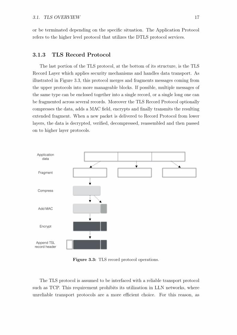
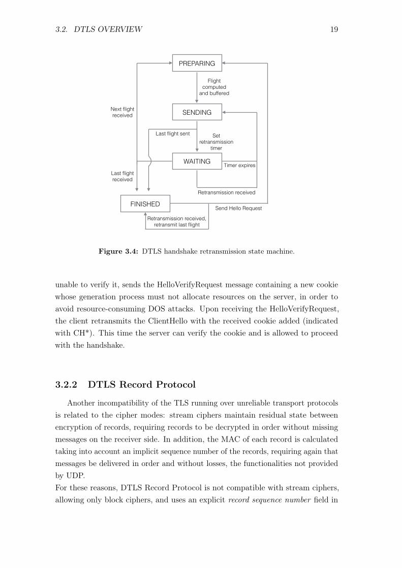
The TLS handshake is not compatible with unreliable transport layer protocolsbecause it would break the handshake process due to message loss or reordering,resulting in the failure of any successive communication. DTLS must then providereliability to handshake messages, and this is done by means of two mechanisms: asimple retransmission timer, represented by the state machine shown in Figure 3.4,and a handshake message number field. Since the handshake messages are groupedin flights, the retransmission mechanism refers to these message groups as a wholeinstead of keeping track of each single message.The handshake message number introduced by DTLS allows the receiver to re-construct the correct order of handshake messages: when a peer receives one ofthem, it can quickly determine whether that message is the expected one or not. Ifso, then it is processed, if not, it is queued for future handling, once all previousmessages have been received.
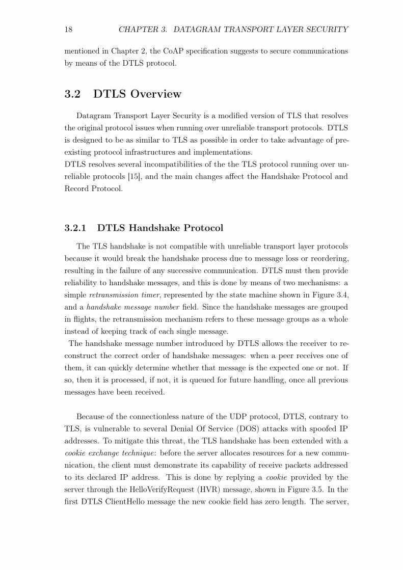
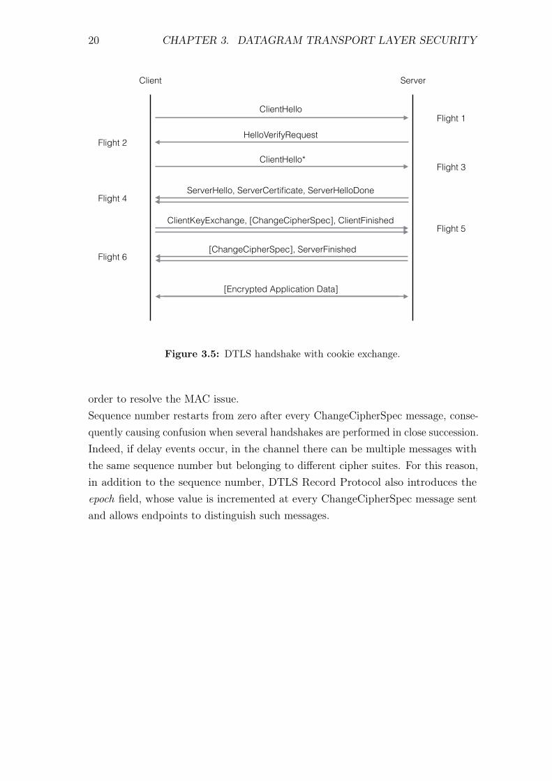
Because of the connectionless nature of the UDP protocol, DTLS, contrary toTLS, is vulnerable to several Denial Of Service (DOS) attacks with spoofed IPaddresses. To mitigate this threat, the TLS handshake has been extended with acookie exchange technique: before the server allocates resources for a new commu-nication, the client must demonstrate its capability of receive packets addressedto its declared IP address. This is done by replying a cookie provided by theserver through the HelloVerifyRequest (HVR) message, shown in Figure 3.5. In thefirst DTLS ClientHello message the new cookie field has zero length. The server,
3.2. DTLS OVERVIEW 19
PREPARING
SENDING
WAITING
FINISHED
Last flight sent
Flight computed
and buffered
Set retransmission
timer
Timer expires
Retransmission received
Last flight received
Next flight received
Retransmission received, retransmit last flight
Send Hello Request
Figure 3.4: DTLS handshake retransmission state machine.
unable to verify it, sends the HelloVerifyRequest message containing a new cookiewhose generation process must not allocate resources on the server, in order toavoid resource-consuming DOS attacks. Upon receiving the HelloVerifyRequest,the client retransmits the ClientHello with the received cookie added (indicatedwith CH*). This time the server can verify the cookie and is allowed to proceedwith the handshake.
3.2.2 DTLS Record Protocol
Another incompatibility of the TLS running over unreliable transport protocolsis related to the cipher modes: stream ciphers maintain residual state betweenencryption of records, requiring records to be decrypted in order without missingmessages on the receiver side. In addition, the MAC of each record is calculatedtaking into account an implicit sequence number of the records, requiring again thatmessages be delivered in order and without losses, the functionalities not providedby UDP.For these reasons, DTLS Record Protocol is not compatible with stream ciphers,allowing only block ciphers, and uses an explicit record sequence number field in
20 CHAPTER 3. DATAGRAM TRANSPORT LAYER SECURITY
Client Server
ClientHello
ServerHello, ServerCertificate, ServerHelloDone
[ChangeCipherSpec], ServerFinished
[Encrypted Application Data]
ClientKeyExchange, [ChangeCipherSpec], ClientFinished
ClientHello*
HelloVerifyRequest
Flight 1
Flight 3
Flight 4
Flight 5
Flight 6
Flight 2
Figure 3.5: DTLS handshake with cookie exchange.
order to resolve the MAC issue.Sequence number restarts from zero after every ChangeCipherSpec message, conse-quently causing confusion when several handshakes are performed in close succession.Indeed, if delay events occur, in the channel there can be multiple messages withthe same sequence number but belonging to different cipher suites. For this reason,in addition to the sequence number, DTLS Record Protocol also introduces theepoch field, whose value is incremented at every ChangeCipherSpec message sentand allows endpoints to distinguish such messages.

Chapter 4
Environment Set-up
The environment used to realize the application developed in this thesis is, forpractical reasons, the same environment used for the CoAP, DTLS and 6LowPANlibraries. In particular, the mote available at the Department of InformationEngineering of the University of Padova at the start of this work was ZolertiaZ1, also used as the testing board during CoAP and DTLS development. Theprogramming language used to build the implementations of the aforementionedprotocols is nesC, a dialectal form of the C programming language purposely createdfor the TinyOS embedded operating system.Furthermore, this chapter introduces the devices used for implementing the wholeprotocol stack, the TinyOS operating system and also the system created to compile,install and debug the application source code.
4.1 Zolertia Z1 Module
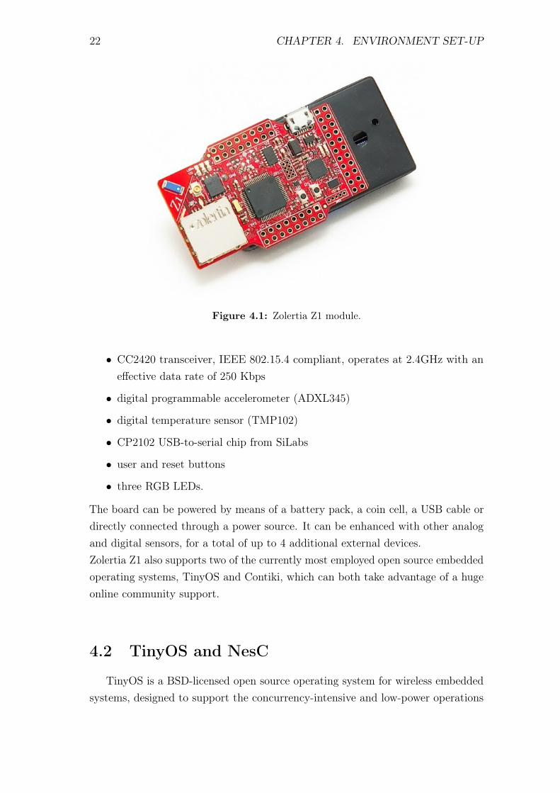
The Z1 module, shown in Figure 4.1, is a general purpose development platformfor wireless sensor networks designed for researchers and developers. This hardwareplatform does not require any external hardware to be programmed. Indeed,due to its built-in full USB capability, it can be directly programmed allowingeasy integration with multiple systems. The mote is equipped with the followinghardware:
• second generation MSP430F2617 low power microcontroller
• 16-bit RISC CPU, 16MHz clock speed, built-in clock factory calibration
• 8KB RAM
• 92KB flash memory
21
22 CHAPTER 4. ENVIRONMENT SET-UP
Figure 4.1: Zolertia Z1 module.
• CC2420 transceiver, IEEE 802.15.4 compliant, operates at 2.4GHz with aneffective data rate of 250 Kbps
• digital programmable accelerometer (ADXL345)
• digital temperature sensor (TMP102)
• CP2102 USB-to-serial chip from SiLabs
• user and reset buttons
• three RGB LEDs.
The board can be powered by means of a battery pack, a coin cell, a USB cable ordirectly connected through a power source. It can be enhanced with other analogand digital sensors, for a total of up to 4 additional external devices.Zolertia Z1 also supports two of the currently most employed open source embeddedoperating systems, TinyOS and Contiki, which can both take advantage of a hugeonline community support.
4.2 TinyOS and NesC
TinyOS is a BSD-licensed open source operating system for wireless embeddedsystems, designed to support the concurrency-intensive and low-power operations
4.2. TINYOS AND NESC 23
required by the constrained devices of IoT networks. It supports several microcon-troller families as well as multiple radio chips, and is composed mainly of a workscheduler and a set of drivers for the most common hardware of wireless embeddedplatforms.
4.2.1 TinyOS Executive Model
Due to the broad range of hardware capabilities of sensor nodes and their verylimited RAM, one of the goals of TinyOS is to have a flexible hardware/softwareboundary. Synchronous code is a piece of code that runs in a single executioncontext thus reserving the CPU access and preventing other code (from hardwareinterrupts or events) execution until its completion, adversely affecting the moteresponsiveness especially when the execution time is long. Rather than makingeverything synchronous, in TinyOS operations that are split-phase (or non-blocking)in hardware are split-phase in software too. Furthermore, all input/output opera-tions that need more than a few hundred microseconds are asynchronous and havea down-call called command, that starts the operation, and a call-back, called event,that signifies operation completion. This feature enables the operating system tomaintain high concurrency with one unique stack but, on the other hand, forcesapplications to have many small event handlers.Due to the concurrency-intensive nature of typical operations of IoT networks,TinyOS provides a form of deferred procedure call, called task, that allows ap-plications to postpone CPU-intensive computations. Tasks are non-preemptiveand run in FIFO order, i.e. their codes run synchronously with respect to each other.
4.2.2 NesC Programming Language
The programming language adopted by the TinyOS operating system is nesC,an extension of the C programming language suited for the hardware limits ofsensor networks and designed to embody the structuring concepts and executionmodel of TinyOS just described.TinyOS code is statistically linked with the application code by a GNU toolchain.In these kind of programs, all the code is contained in a single executable module,and thus the efficiency of the library referencing operations is improved. However,as a drawback, the memory code size increases.The model of TinyOS applications is component-based, which means that eachapplication is composed of one or more software components interconnected by
24 CHAPTER 4. ENVIRONMENT SET-UP
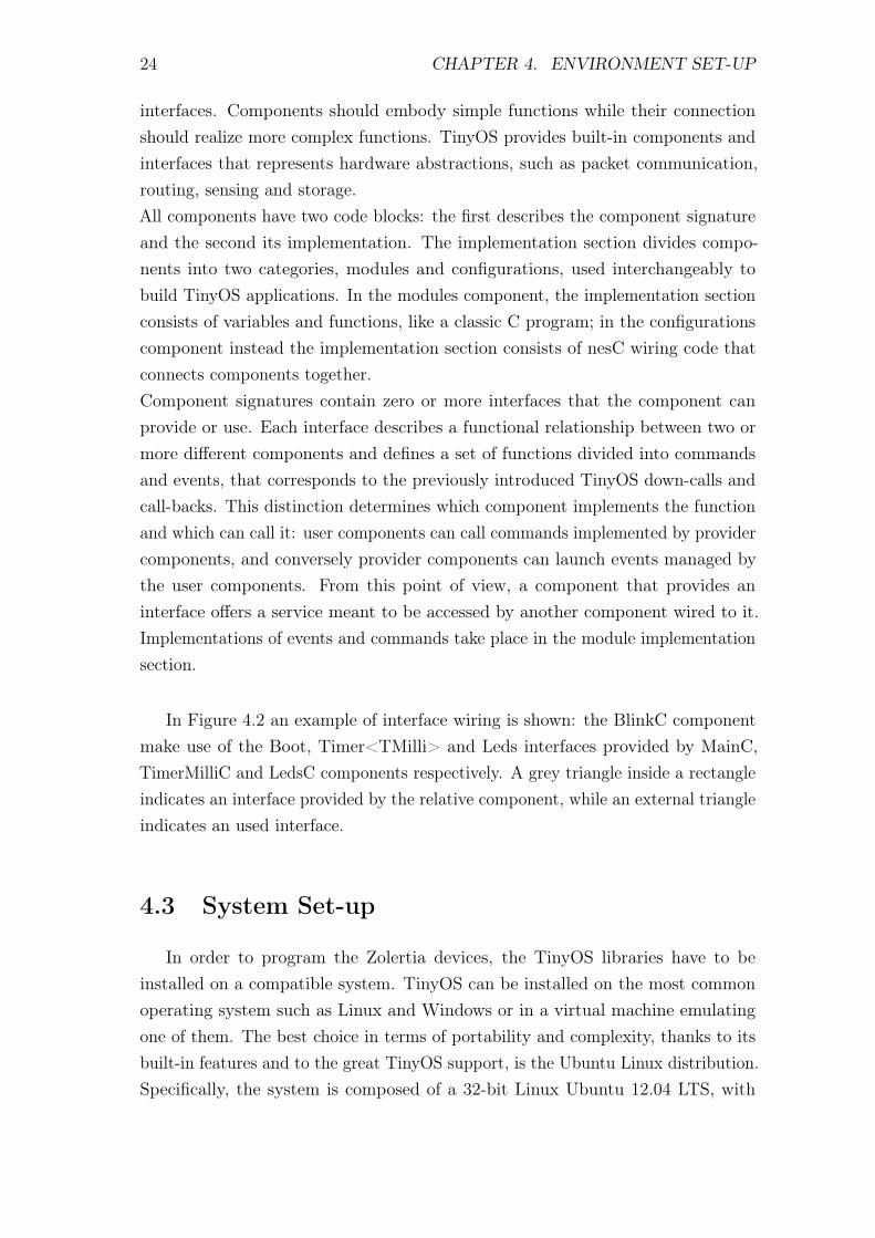
interfaces. Components should embody simple functions while their connectionshould realize more complex functions. TinyOS provides built-in components andinterfaces that represents hardware abstractions, such as packet communication,routing, sensing and storage.All components have two code blocks: the first describes the component signatureand the second its implementation. The implementation section divides compo-nents into two categories, modules and configurations, used interchangeably tobuild TinyOS applications. In the modules component, the implementation sectionconsists of variables and functions, like a classic C program; in the configurationscomponent instead the implementation section consists of nesC wiring code thatconnects components together.Component signatures contain zero or more interfaces that the component canprovide or use. Each interface describes a functional relationship between two ormore different components and defines a set of functions divided into commandsand events, that corresponds to the previously introduced TinyOS down-calls andcall-backs. This distinction determines which component implements the functionand which can call it: user components can call commands implemented by providercomponents, and conversely provider components can launch events managed bythe user components. From this point of view, a component that provides aninterface offers a service meant to be accessed by another component wired to it.Implementations of events and commands take place in the module implementationsection.
In Figure 4.2 an example of interface wiring is shown: the BlinkC componentmake use of the Boot, Timer<TMilli> and Leds interfaces provided by MainC,TimerMilliC and LedsC components respectively. A grey triangle inside a rectangleindicates an interface provided by the relative component, while an external triangleindicates an used interface.
4.3 System Set-up
In order to program the Zolertia devices, the TinyOS libraries have to beinstalled on a compatible system. TinyOS can be installed on the most commonoperating system such as Linux and Windows or in a virtual machine emulatingone of them. The best choice in terms of portability and complexity, thanks to itsbuilt-in features and to the great TinyOS support, is the Ubuntu Linux distribution.Specifically, the system is composed of a 32-bit Linux Ubuntu 12.04 LTS, with
4.3. SYSTEM SET-UP 25
BlinkC
TimerMilliCMainC LedsC
Timer<TMilli> LedsBoot
Figure 4.2: BlinkC wiring example.
kernel 3.8.0, virtualized by the VMware Fusion software running on a 2012 Macbookair with 1 GB of RAM and 2 virtual cores of the 1.8 GHz Intel Core i5. The TinyOSversion installed on the linux distribution is 2.1.2, coupled with the GCC MSP430compiler version 4.6.3. The procedure followed for the installation of TinyOS andthe MSP430 toolchain is presented in [1].Furthermore, two Zolertia Z1 motes have been connected and powered via two USBcables, completing the environment setup.

Chapter 5
BlinkToSCoAP Implementation
In Chapter 2 and Chapter 3 two fundamental IoT network protocols have beendescribed, one providing web services and the other end-to-end security functionali-ties. This chapter presents an application called BlinkToSCoAP, intended to runover 6LoWPAN networks, which includes a DTLS secured CoAP implementation.In the following section, the TinyOS libraries that implement these protocols arebriefly presented and then a detailed description the BlinkToSCoAP application isgiven. The last section of the chapter describes another application, called Blink-ToCoAP, obtained by depriving BlinkToSCoAP of the security components. Thepurpose of this second application is to allow the evaluation of DTLS performancethrough the experiments that will be presented in the following chapter.
5.1 Protocol Libraries
This section contains a brief description of the libraries utilized to assemble theBlinkToSCoAP and BlinkToCoAP applications. These components implement alightweight and unoptimized version of the protocols, and all their authors belongto the SIGNET Group of the University of Padova’s Department of InformationEngineering (DEI).
5.1.1 CoAP Protocol Library
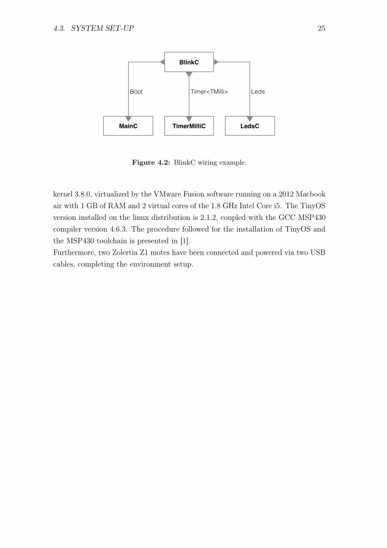
The CoAP library has been developed by Angelo P. Castellani and Mattia Gheda.The code structure, depicted in Figure 5.1, is composed of a main component, calledCoAP, and an auxiliary component called TimedPool. The first one provides twodifferent interfaces, CoAPClient and CoAPServer, that offer to other componentsCoAP client and CoAP server functionalities respectively. While CoAP modulehandles all the CoAP request/response messages and all the protocol mechanisms,
27
28 CHAPTER 5. BLINKTOSCOAP IMPLEMENTATION
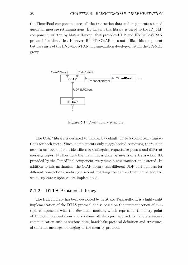
the TimedPool component stores all the transaction data and implements a timedqueue for message retransmissions. By default, this library is wired to the IP_6LPcomponent, written by Matus Harvan, that provides UDP and IPv6/6LoWPANprotocol functionalities. However, BlinkToSCoAP does not utilize this componentbut uses instead the IPv6/6LoWPAN implementation developed within the SIGNETgroup.
CoAP
IP_6LP
TimedPool
UDP6LPClient
TransactionPool
CoAPClient CoAPServer
Figure 5.1: CoAP library structure.
The CoAP library is designed to handle, by default, up to 5 concurrent transac-tions for each mote. Since it implements only piggy-backed responses, there is noneed to use two different identifiers to distinguish requests/responses and differentmessage types. Furthermore the matching is done by means of a transaction ID,provided by the TimedPool component every time a new transaction is stored. Inaddition to this mechanism, the CoAP library uses different UDP port numbers fordifferent transactions, realizing a second matching mechanism that can be adoptedwhen separate responses are implemented.
5.1.2 DTLS Protocol Library
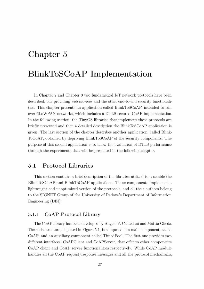
The DTLS library has been developed by Cristiano Tapparello. It is a lightweightimplementation of the DTLS protocol and is based on the interconnection of mul-tiple components with the dtls main module, which represents the entry pointof DTLS implementation and contains all its logic required to handle a securecommunication such as sessions data, handshake protocol definition and structuresof different messages belonging to the security protocol.
5.1. PROTOCOL LIBRARIES 29
dtlsDTLS
Pool
Rijndael
CCM
RandomRandom
LocalTimeMilliLocalTime
CryptoCrypto
HMacHMac
PoolPeerStoragePool
NetQNetQ
Sha2
Pool
Pool
CipherStoragePool
Rijndael
CCM
HMacStoragePool
Sha2
NetQStoragePool
Figure 5.2: DTLS library structure.
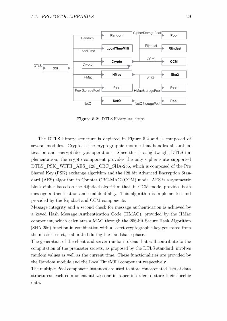
The DTLS library structure is depicted in Figure 5.2 and is composed ofseveral modules. Crypto is the cryptographic module that handles all authen-tication and encrypt/decrypt operations. Since this is a lightweight DTLS im-plementation, the crypto component provides the only cipher suite supportedDTLS_PSK_WITH_AES_128_CBC_SHA-256, which is composed of the PreShared Key (PSK) exchange algorithm and the 128 bit Advanced Encryption Stan-dard (AES) algorithm in Counter CBC-MAC (CCM) mode. AES is a symmetricblock cipher based on the Rijndael algorithm that, in CCM mode, provides bothmessage authentication and confidentiality. This algorithm is implemented andprovided by the Rijndael and CCM components.Message integrity and a second check for message authentication is achieved bya keyed Hash Message Authentication Code (HMAC), provided by the HMaccomponent, which calculates a MAC through the 256-bit Secure Hash Algorithm(SHA-256) function in combination with a secret cryptographic key generated fromthe master secret, elaborated during the handshake phase.The generation of the client and server random tokens that will contribute to thecomputation of the premaster secrets, as proposed by the DTLS standard, involvesrandom values as well as the current time. These functionalities are provided bythe Random module and the LocalTimeMilli component respectively.The multiple Pool component instances are used to store concatenated lists of datastructures: each component utilizes one instance in order to store their specificdata.
30 CHAPTER 5. BLINKTOSCOAP IMPLEMENTATION
The NetQ module implements a concatenated list meant to provide, coupled witha timer, reliability feature to handshake messages. However this feature is still notfully developed.From Figure 5.2, it can be seen that, differently from the CoAP structure, theDTLS component does not have a vertical architecture. Instead of providing itsfunctionalities upwards for components of higher layers, and utilize functionalitiesprovided by lower layer components, the dtls component can be wired only throughits unique interface DTLS.
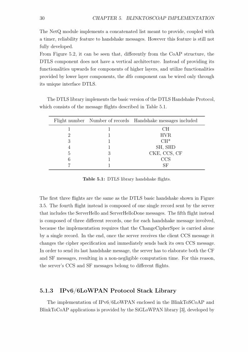
The DTLS library implements the basic version of the DTLS Handshake Protocol,which consists of the message flights described in Table 5.1.
Flight number Number of records Handshake messages included
1 1 CH2 1 HVR3 1 CH*4 1 SH, SHD5 3 CKE, CCS, CF6 1 CCS7 1 SF
Table 5.1: DTLS library handshake flights.
The first three flights are the same as the DTLS basic handshake shown in Figure3.5. The fourth flight instead is composed of one single record sent by the serverthat includes the ServerHello and ServerHelloDone messages. The fifth flight insteadis composed of three different records, one for each handshake message involved,because the implementation requires that the ChangeCipherSpec is carried aloneby a single record. In the end, once the server receives the client CCS message itchanges the cipher specification and immediately sends back its own CCS message.In order to send its last handshake message, the server has to elaborate both the CFand SF messages, resulting in a non-negligible computation time. For this reason,the server’s CCS and SF messages belong to different flights.
5.1.3 IPv6/6LoWPAN Protocol Stack Library
The implementation of IPv6/6LoWPAN enclosed in the BlinkToSCoAP andBlinkToCoAP applications is provided by the SiGLoWPAN library [3], developed by
5.1. PROTOCOL LIBRARIES 31
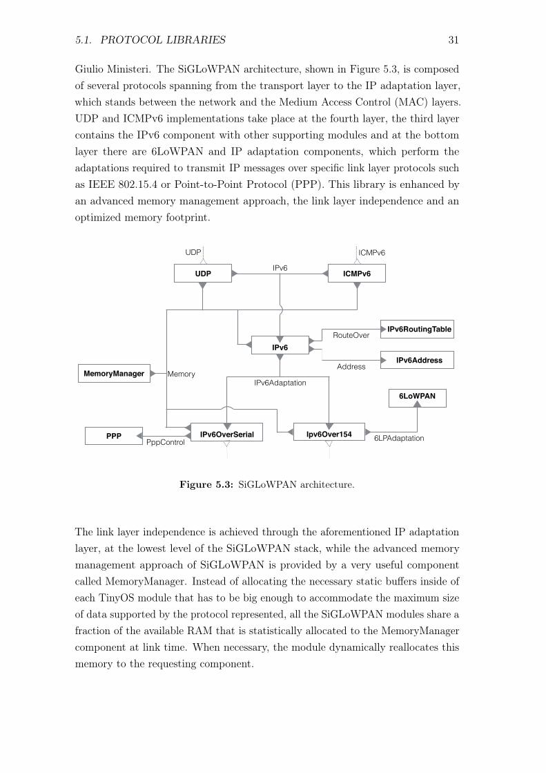
Giulio Ministeri. The SiGLoWPAN architecture, shown in Figure 5.3, is composedof several protocols spanning from the transport layer to the IP adaptation layer,which stands between the network and the Medium Access Control (MAC) layers.UDP and ICMPv6 implementations take place at the fourth layer, the third layercontains the IPv6 component with other supporting modules and at the bottomlayer there are 6LoWPAN and IP adaptation components, which perform theadaptations required to transmit IP messages over specific link layer protocols suchas IEEE 802.15.4 or Point-to-Point Protocol (PPP). This library is enhanced byan advanced memory management approach, the link layer independence and anoptimized memory footprint.
IPv6RoutingTable
IPv6
MemoryManagerAddress
RouteOver
UDP ICMPv6
IPv6 IPv6Address
PppControlIPv6OverSerial Ipv6Over154
6LoWPAN
PPP
IPv6Adaptation
6LPAdaptation
Memory
UDP ICMPv6
Figure 5.3: SiGLoWPAN architecture.
The link layer independence is achieved through the aforementioned IP adaptationlayer, at the lowest level of the SiGLoWPAN stack, while the advanced memorymanagement approach of SiGLoWPAN is provided by a very useful componentcalled MemoryManager. Instead of allocating the necessary static buffers inside ofeach TinyOS module that has to be big enough to accommodate the maximum sizeof data supported by the protocol represented, all the SiGLoWPAN modules share afraction of the available RAM that is statistically allocated to the MemoryManagercomponent at link time. When necessary, the module dynamically reallocates thismemory to the requesting component.
32 CHAPTER 5. BLINKTOSCOAP IMPLEMENTATION
Other details of the SiGLoWPAN stack are beyond the scope of this thesis andcan be found in [3].
5.2 BlinkToSCoAP Application
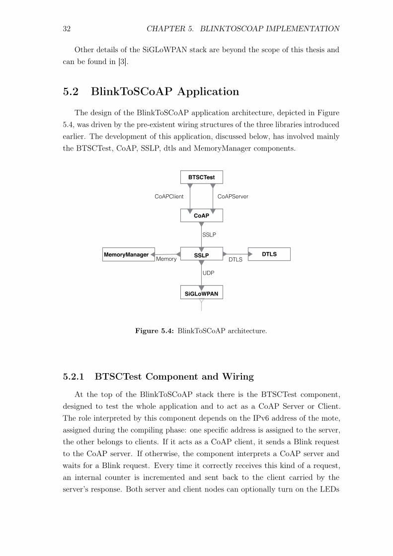
The design of the BlinkToSCoAP application architecture, depicted in Figure5.4, was driven by the pre-existent wiring structures of the three libraries introducedearlier. The development of this application, discussed below, has involved mainlythe BTSCTest, CoAP, SSLP, dtls and MemoryManager components.
CoAP
CoAPClient
BTSCTest
CoAPServer
SSLP DTLSDTLS
SiGLoWPAN
SSLP
UDP
MemoryManagerMemory
Figure 5.4: BlinkToSCoAP architecture.
5.2.1 BTSCTest Component and Wiring
At the top of the BlinkToSCoAP stack there is the BTSCTest component,designed to test the whole application and to act as a CoAP Server or Client.The role interpreted by this component depends on the IPv6 address of the mote,assigned during the compiling phase: one specific address is assigned to the server,the other belongs to clients. If it acts as a CoAP client, it sends a Blink requestto the CoAP server. If otherwise, the component interprets a CoAP server andwaits for a Blink request. Every time it correctly receives this kind of a request,an internal counter is incremented and sent back to the client carried by theserver’s response. Both server and client nodes can optionally turn on the LEDs
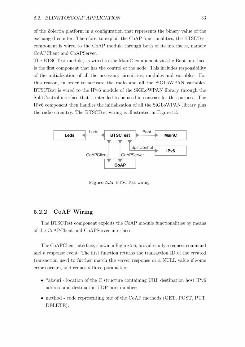
5.2. BLINKTOSCOAP APPLICATION 33
of the Zolertia platform in a configuration that represents the binary value of theexchanged counter. Therefore, to exploit the CoAP functionalities, the BTSCTestcomponent is wired to the CoAP module through both of its interfaces, namelyCoAPClient and CoAPServer.The BTSCTest module, as wired to the MainC component via the Boot interface,is the first component that has the control of the node. This includes responsibilityof the initialization of all the necessary circuitries, modules and variables. Forthis reason, in order to activate the radio and all the SiGLoWPAN variables,BTSCTest is wired to the IPv6 module of the SiGLoWPAN library through theSplitControl interface that is intended to be used in contrast for this purpose. TheIPv6 component then handles the initialization of all the SiGLoWPAN library plusthe radio circuitry. The BTSCTest wiring is illustrated in Figure 5.5.
CoAP
CoAPClient
BTSCTest MainCBoot
LedsLeds
CoAPServerIPv6
SplitControl
Figure 5.5: BTSCTest wiring.
5.2.2 CoAP Wiring
The BTSCTest component exploits the CoAP module functionalities by meansof the CoAPClient and CoAPServer interfaces.
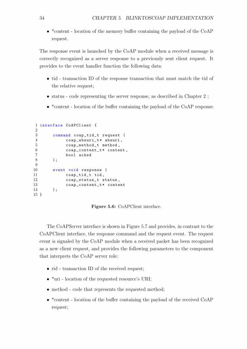
The CoAPClient interface, shown in Figure 5.6, provides only a request commandand a response event. The first function returns the transaction ID of the createdtransaction used to further match the server response or a NULL value if someerrors occurs, and requests three parameters:
• *absuri - location of the C structure containing URI, destination host IPv6address and destination UDP port number;
• method - code representing one of the CoAP methods (GET, POST, PUT,DELETE);
34 CHAPTER 5. BLINKTOSCOAP IMPLEMENTATION
• *content - location of the memory buffer containing the payload of the CoAPrequest.
The response event is launched by the CoAP module when a received message iscorrectly recognized as a server response to a previously sent client request. Itprovides to the event handler function the following data:
• tid - transaction ID of the response transaction that must match the tid ofthe relative request;
• status - code representing the server response, as described in Chapter 2 ;
• *content - location of the buffer containing the payload of the CoAP response.
1 interface CoAPClient 23 command coap_tid_t request (4 coap_absuri_t* absuri ,5 coap_method_t method ,6 coap_content_t* content ,7 bool acked8 );910 event void response (11 coap_tid_t tid ,12 coap_status_t status ,13 coap_content_t* content14 );15
Figure 5.6: CoAPClient interface.
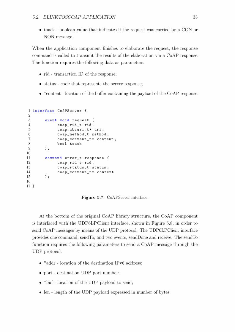
The CoAPServer interface is shown in Figure 5.7 and provides, in contrast to theCoAPClient interface, the response command and the request event. The requestevent is signaled by the CoAP module when a received packet has been recognizedas a new client request, and provides the following parameters to the componentthat interprets the CoAP server role:
• rid - transaction ID of the received request;
• *uri - location of the requested resource’s URI;
• method - code that represents the requested method;
• *content - location of the buffer containing the payload of the received CoAPrequest;
5.2. BLINKTOSCOAP APPLICATION 35
• toack - boolean value that indicates if the request was carried by a CON orNON message.
When the application component finishes to elaborate the request, the responsecommand is called to transmit the results of the elaboration via a CoAP response.The function requires the following data as parameters:
• rid - transaction ID of the response;
• status - code that represents the server response;
• *content - location of the buffer containing the payload of the CoAP response.
1 interface CoAPServer 23 event void request (4 coap_rid_t rid ,5 coap_absuri_t* uri ,6 coap_method_t method ,7 coap_content_t* content ,8 bool toack9 );1011 command error_t response (12 coap_rid_t rid ,13 coap_status_t status ,14 coap_content_t* content15 );1617
Figure 5.7: CoAPServer interface.
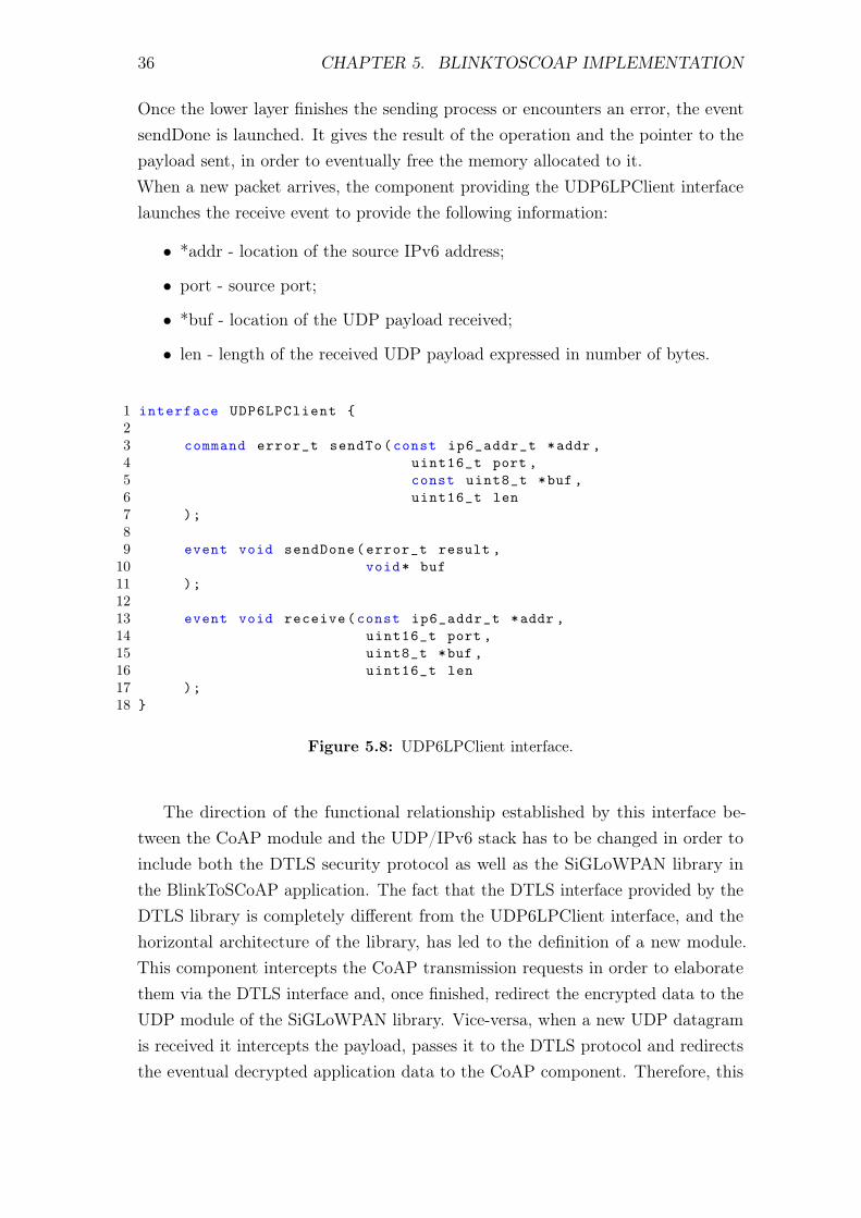
At the bottom of the original CoAP library structure, the CoAP componentis interfaced with the UDP6LPClient interface, shown in Figure 5.8, in order tosend CoAP messages by means of the UDP protocol. The UDP6LPClient interfaceprovides one command, sendTo, and two events, sendDone and receive. The sendTofunction requires the following parameters to send a CoAP message through theUDP protocol:
• *addr - location of the destination IPv6 address;
• port - destination UDP port number;
• *buf - location of the UDP payload to send;
• len - length of the UDP payload expressed in number of bytes.
36 CHAPTER 5. BLINKTOSCOAP IMPLEMENTATION
Once the lower layer finishes the sending process or encounters an error, the eventsendDone is launched. It gives the result of the operation and the pointer to thepayload sent, in order to eventually free the memory allocated to it.When a new packet arrives, the component providing the UDP6LPClient interfacelaunches the receive event to provide the following information:
• *addr - location of the source IPv6 address;
• port - source port;
• *buf - location of the UDP payload received;
• len - length of the received UDP payload expressed in number of bytes.
1 interface UDP6LPClient 23 command error_t sendTo(const ip6_addr_t *addr ,4 uint16_t port ,5 const uint8_t *buf ,6 uint16_t len7 );89 event void sendDone(error_t result ,10 void* buf11 );1213 event void receive(const ip6_addr_t *addr ,14 uint16_t port ,15 uint8_t *buf ,16 uint16_t len17 );18
Figure 5.8: UDP6LPClient interface.
The direction of the functional relationship established by this interface be-tween the CoAP module and the UDP/IPv6 stack has to be changed in order toinclude both the DTLS security protocol as well as the SiGLoWPAN library inthe BlinkToSCoAP application. The fact that the DTLS interface provided by theDTLS library is completely different from the UDP6LPClient interface, and thehorizontal architecture of the library, has led to the definition of a new module.This component intercepts the CoAP transmission requests in order to elaboratethem via the DTLS interface and, once finished, redirect the encrypted data to theUDP module of the SiGLoWPAN library. Vice-versa, when a new UDP datagramis received it intercepts the payload, passes it to the DTLS protocol and redirectsthe eventual decrypted application data to the CoAP component. Therefore, this
5.2. BLINKTOSCOAP APPLICATION 37
new module is directly wired with CoAP, SiGLoWPAN and DTLS components,acting like a gateway for the data flowing between them.
5.2.3 SSLP Component and DTLS, SiGLoWPAN Wiring
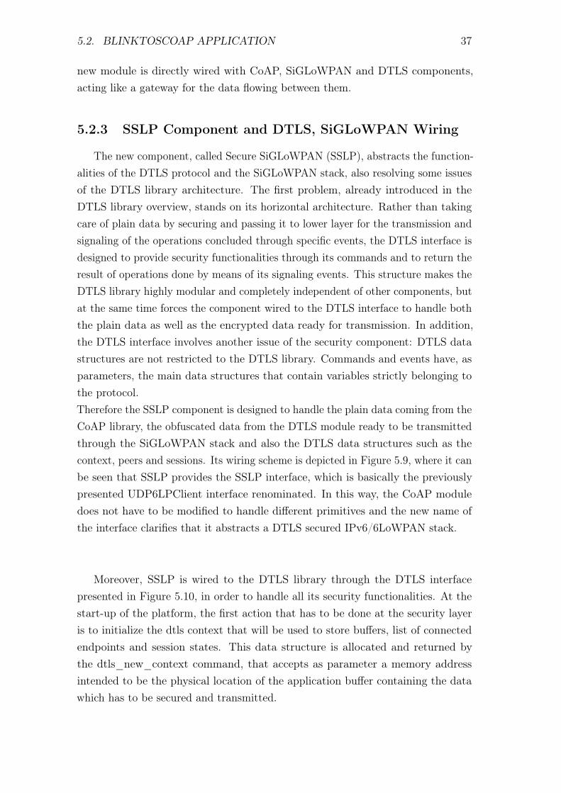
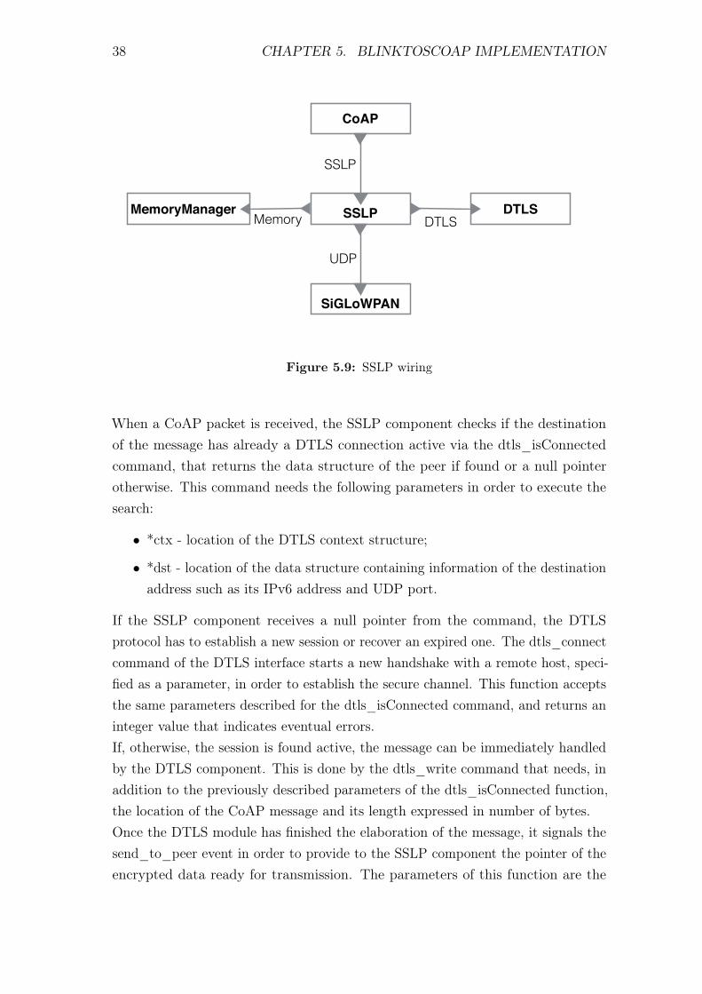
The new component, called Secure SiGLoWPAN (SSLP), abstracts the function-alities of the DTLS protocol and the SiGLoWPAN stack, also resolving some issuesof the DTLS library architecture. The first problem, already introduced in theDTLS library overview, stands on its horizontal architecture. Rather than takingcare of plain data by securing and passing it to lower layer for the transmission andsignaling of the operations concluded through specific events, the DTLS interface isdesigned to provide security functionalities through its commands and to return theresult of operations done by means of its signaling events. This structure makes theDTLS library highly modular and completely independent of other components, butat the same time forces the component wired to the DTLS interface to handle boththe plain data as well as the encrypted data ready for transmission. In addition,the DTLS interface involves another issue of the security component: DTLS datastructures are not restricted to the DTLS library. Commands and events have, asparameters, the main data structures that contain variables strictly belonging tothe protocol.Therefore the SSLP component is designed to handle the plain data coming from theCoAP library, the obfuscated data from the DTLS module ready to be transmittedthrough the SiGLoWPAN stack and also the DTLS data structures such as thecontext, peers and sessions. Its wiring scheme is depicted in Figure 5.9, where it canbe seen that SSLP provides the SSLP interface, which is basically the previouslypresented UDP6LPClient interface renominated. In this way, the CoAP moduledoes not have to be modified to handle different primitives and the new name ofthe interface clarifies that it abstracts a DTLS secured IPv6/6LoWPAN stack.
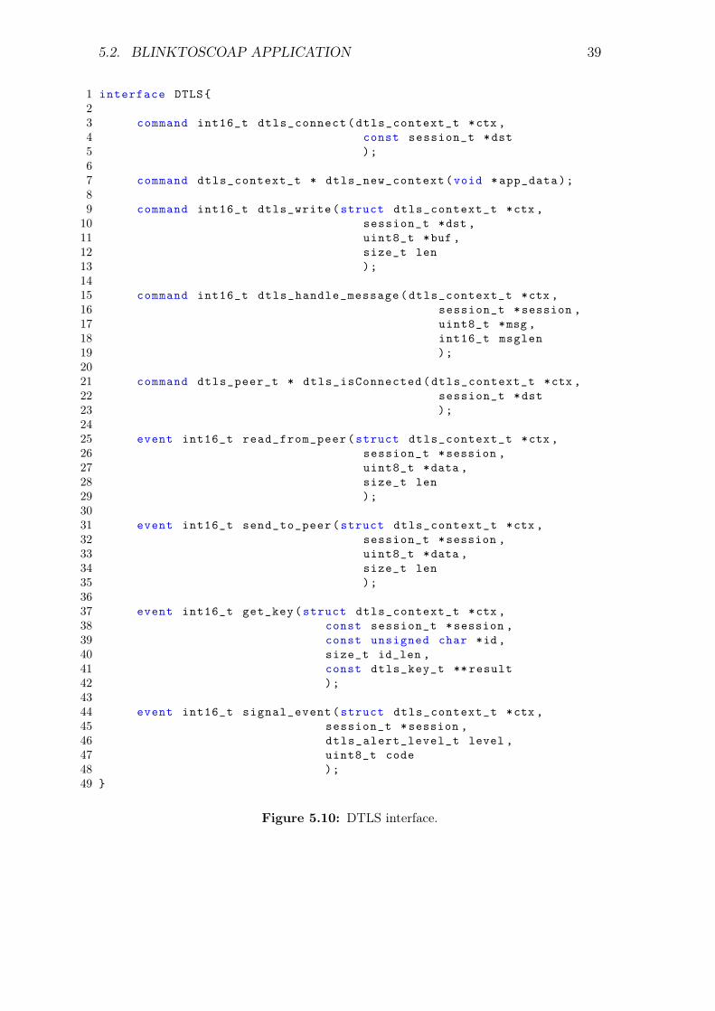
Moreover, SSLP is wired to the DTLS library through the DTLS interfacepresented in Figure 5.10, in order to handle all its security functionalities. At thestart-up of the platform, the first action that has to be done at the security layeris to initialize the dtls context that will be used to store buffers, list of connectedendpoints and session states. This data structure is allocated and returned bythe dtls_new_context command, that accepts as parameter a memory addressintended to be the physical location of the application buffer containing the datawhich has to be secured and transmitted.
38 CHAPTER 5. BLINKTOSCOAP IMPLEMENTATION
SiGLoWPAN
UDP
SSLP DTLSDTLS
CoAP
SSLP
MemoryManagerMemory
Figure 5.9: SSLP wiring
When a CoAP packet is received, the SSLP component checks if the destinationof the message has already a DTLS connection active via the dtls_isConnectedcommand, that returns the data structure of the peer if found or a null pointerotherwise. This command needs the following parameters in order to execute thesearch:
• *ctx - location of the DTLS context structure;
• *dst - location of the data structure containing information of the destinationaddress such as its IPv6 address and UDP port.
If the SSLP component receives a null pointer from the command, the DTLSprotocol has to establish a new session or recover an expired one. The dtls_connectcommand of the DTLS interface starts a new handshake with a remote host, speci-fied as a parameter, in order to establish the secure channel. This function acceptsthe same parameters described for the dtls_isConnected command, and returns aninteger value that indicates eventual errors.If, otherwise, the session is found active, the message can be immediately handledby the DTLS component. This is done by the dtls_write command that needs, inaddition to the previously described parameters of the dtls_isConnected function,the location of the CoAP message and its length expressed in number of bytes.Once the DTLS module has finished the elaboration of the message, it signals thesend_to_peer event in order to provide to the SSLP component the pointer of theencrypted data ready for transmission. The parameters of this function are the
5.2. BLINKTOSCOAP APPLICATION 39
1 interface DTLS23 command int16_t dtls_connect(dtls_context_t *ctx ,4 const session_t *dst5 );67 command dtls_context_t * dtls_new_context(void *app_data);89 command int16_t dtls_write(struct dtls_context_t *ctx ,10 session_t *dst ,11 uint8_t *buf ,12 size_t len13 );1415 command int16_t dtls_handle_message(dtls_context_t *ctx ,16 session_t *session ,17 uint8_t *msg ,18 int16_t msglen19 );2021 command dtls_peer_t * dtls_isConnected(dtls_context_t *ctx ,22 session_t *dst23 );2425 event int16_t read_from_peer(struct dtls_context_t *ctx ,26 session_t *session ,27 uint8_t *data ,28 size_t len29 );3031 event int16_t send_to_peer(struct dtls_context_t *ctx ,32 session_t *session ,33 uint8_t *data ,34 size_t len35 );3637 event int16_t get_key(struct dtls_context_t *ctx ,38 const session_t *session ,39 const unsigned char *id ,40 size_t id_len ,41 const dtls_key_t ** result42 );4344 event int16_t signal_event(struct dtls_context_t *ctx ,45 session_t *session ,46 dtls_alert_level_t level ,47 uint8_t code48 );49
Figure 5.10: DTLS interface.
40 CHAPTER 5. BLINKTOSCOAP IMPLEMENTATION
same as that of the dtls_write command: the dtls context, the session structure oftransmission, the memory address of the obfuscated message and its total length.When a new message arrives from the UDP protocol, the SSLP component expectsthat it is a DTLS packet. Furthermore, it passes the data directly to the DTLSmodule through the dtls_handle_message command.If DTLS recognizes the received packet as a valid application message, it decrypts itand launches the read_to_peer event, where the SSLP forwards the decrypted datato the CoAP layer. If the received message is recognized as a DTLS alert message,the security module signals it via the signal_event function, which provides asparameters the code and the level of the alert message in addition to the dtls contextand the session structure. This particular functionality is not yet implemented inthe code. As the last case, if the received packet is a handshake message, the DTLSlibrary will process it and follow the handshake protocol specification.The last function of the DTLS interface is the get_key event, used to retrieve thepre-shared key and its ID from the mote. Actually, the key recovery functionalityis not yet implemented, and the operation is thus bypassed by the SSLP module byproviding the values written directly on its source code.
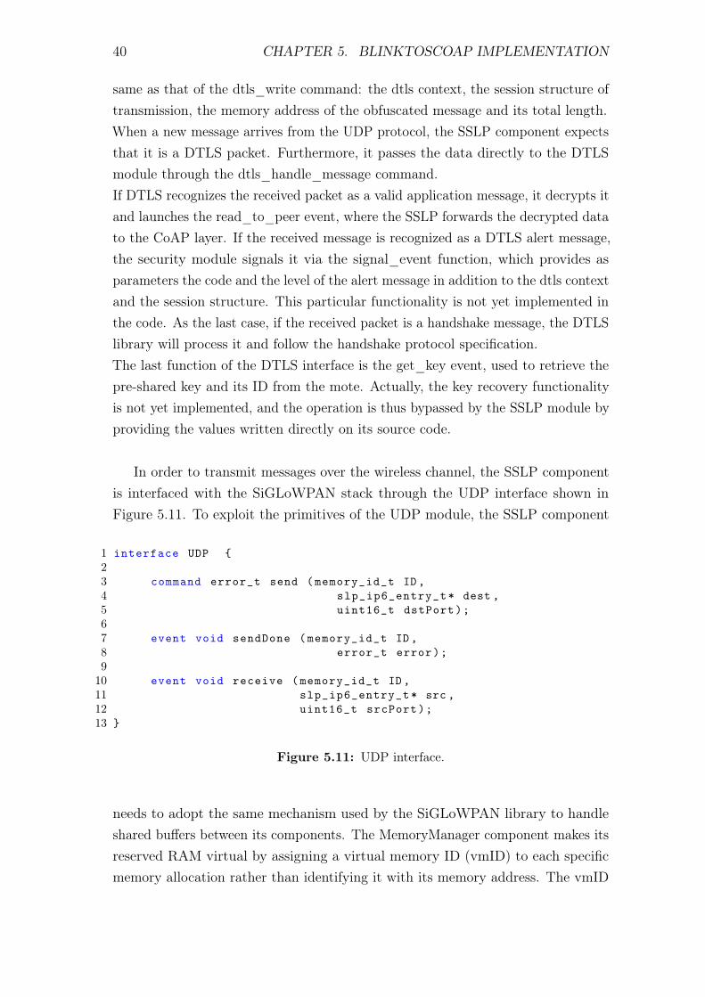
In order to transmit messages over the wireless channel, the SSLP componentis interfaced with the SiGLoWPAN stack through the UDP interface shown inFigure 5.11. To exploit the primitives of the UDP module, the SSLP component
1 interface UDP 23 command error_t send (memory_id_t ID ,4 slp_ip6_entry_t* dest ,5 uint16_t dstPort);67 event void sendDone (memory_id_t ID,8 error_t error);910 event void receive (memory_id_t ID,11 slp_ip6_entry_t* src ,12 uint16_t srcPort);13
Figure 5.11: UDP interface.
needs to adopt the same mechanism used by the SiGLoWPAN library to handleshared buffers between its components. The MemoryManager component makes itsreserved RAM virtual by assigning a virtual memory ID (vmID) to each specificmemory allocation rather than identifying it with its memory address. The vmID
5.2. BLINKTOSCOAP APPLICATION 41
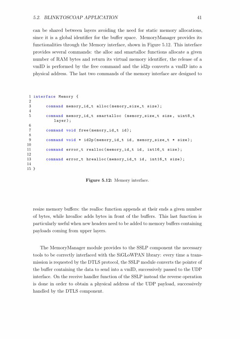
can be shared between layers avoiding the need for static memory allocations,since it is a global identifier for the buffer space. MemoryManager provides itsfunctionalities through the Memory interface, shown in Figure 5.12. This interfaceprovides several commands: the alloc and smartalloc functions allocate a givennumber of RAM bytes and return its virtual memory identifier, the release of avmID is performed by the free command and the id2p converts a vmID into aphysical address. The last two commands of the memory interface are designed to
1 interface Memory 23 command memory_id_t alloc(memory_size_t size);45 command memory_id_t smartalloc (memory_size_t size , uint8_t
layer);67 command void free(memory_id_t id);89 command void * id2p(memory_id_t id , memory_size_t * size);1011 command error_t realloc(memory_id_t id , int16_t size);1213 command error_t hrealloc(memory_id_t id , int16_t size);1415
Figure 5.12: Memory interface.
resize memory buffers: the realloc function appends at their ends a given numberof bytes, while hrealloc adds bytes in front of the buffers. This last function isparticularly useful when new headers need to be added to memory buffers containingpayloads coming from upper layers.
The MemoryManager module provides to the SSLP component the necessarytools to be correctly interfaced with the SiGLoWPAN library: every time a trans-mission is requested by the DTLS protocol, the SSLP module converts the pointer ofthe buffer containing the data to send into a vmID, successively passed to the UDPinterface. On the receive handler function of the SSLP instead the reverse operationis done in order to obtain a physical address of the UDP payload, successivelyhandled by the DTLS component.
42 CHAPTER 5. BLINKTOSCOAP IMPLEMENTATION
5.2.4 Practical Issues
During the development of the BlinkToSCoAP application, some practical issueshave been encountered, as described below.
Compiler dependent implementation Before the BlinkToSCoAP applicationhas been finished, when the DTLS component was being analyzed and tested,the system setup had installed the most recent version of the GNU mspgcctoolchain, specifically the 4.7.0 version. This was causing the failure of theDTLS decryption process, problem no more encountered if the 4.6.3 compilerwas used. This issue has evidenced the presence of some compiler-dependentfunction or operation of the DTLS encrypt/decrypt section. Actually thisissue is not yet resolved.
Data structure incompatibilities The first issue is related to the data structureincompatibility between the different libraries used to assemble the whole ap-plication. In particular, these incompatibilities have taken place in the SSLPcomponent where the destination endpoint is represented by the DTLS compo-nent as a session_t structure and by the UDP module as a slp_ip6_entry_tstructure.In order to fix this problem, the optimal solution should have been the con-version of all the destination representations to an unique data structure,either modifying the DTLS or the SiGLoWPAN source code. Unfortunately,this involves a lot of modifications and time, independently from the datastructure chosen, and for this reason a sub-optimal solution has been adopted:the SSLP module performs data structure conversion every time it is needed.
RAM usage The total RAM available on the Zolertia Z1 platform is 8KB. Oncethe BlinkToSCoAP application has been finished, with the configurations ofall the libraries set to their default values, the compilation procedure wasfailing due to a RAM region overflowing of about 500 bytes. In order to reducethe memory consumption of the application, some configuration parametershave been reduced, more specifically, in the CoAP library:
• COAP_MAX_CONNECTIONS = 2 - maximum CoAP contemporane-ous active transactions;
while in the SiGLoWPAN library:
• SLP_IPV6_QUEUE = 3 - maximum queue dimension for IPv6 packets;
5.3. BLINKTOCOAP 43
• SLP_IPV6_MAX_ADDR = 1 - maximum number of IPv6 addresses anode can have at the same time;
• SLP_ROUTES = 3 - number of entries in the SiGLoWPAN IPv6 routingtable;
• SLP_MEMORY_SIZE = 500 - number of RAM bytes dedicated to thedynamic management of the MemoryManager component.
In addiction of these modifications, the DTLS has been optimized by elimi-nating some redundant code and variables.
UDP ports As already mentioned, the CoAP library implements a request/re-sponse matching mechanism based on different adjacent UDP port numbers.Unfortunately, the SiGLoWPAN implementation uses these parameters tooffer multiple instances of the UDP interface, allowing multiple componentsto be linked to the same protocol but forcing them to use a predeterminednumber of UDP ports. Since the CoAP library implements only piggy-backedresponses, this matching mechanism is momentarily disabled until separateresponses are added to implementation. The CoAP module therefore uses asingle UDP port to handle all its transactions.
5.3 BlinkToCoAP
The BlinkToCoAP application is equivalent to BlinkToSCoAP, except for thepresence of the DTLS security layer. Its structure is shown in Figure 5.13. Since itspurpose is to evidence the performance variation brought in by the DTLS module,the BlinkToCoAP application is designed to be as close as possible to its securedversion. Specifically, their differences involve only the wiring of the CoAP module,which – in this application – is interfaced directly to the UDP protocol. As can beseen from the BlinkToCoAP architecture, and as already discussed above, CoAPis wired to the MemoryManager component in order to correctly relate with theSiGLoWPAN library.
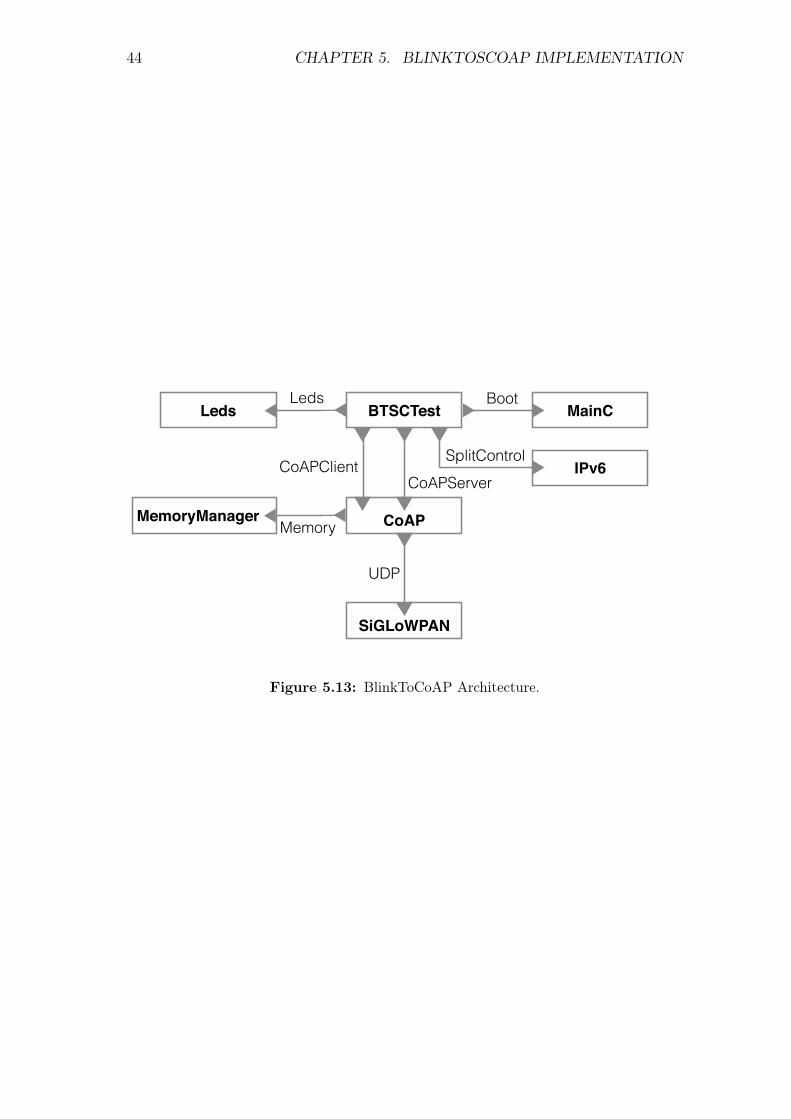
44 CHAPTER 5. BLINKTOSCOAP IMPLEMENTATION
CoAP
CoAPClient
BTSCTest MainCBoot
LedsLeds
CoAPServerIPv6
SplitControl
SiGLoWPAN
UDP
MemoryManagerMemory
Figure 5.13: BlinkToCoAP Architecture.
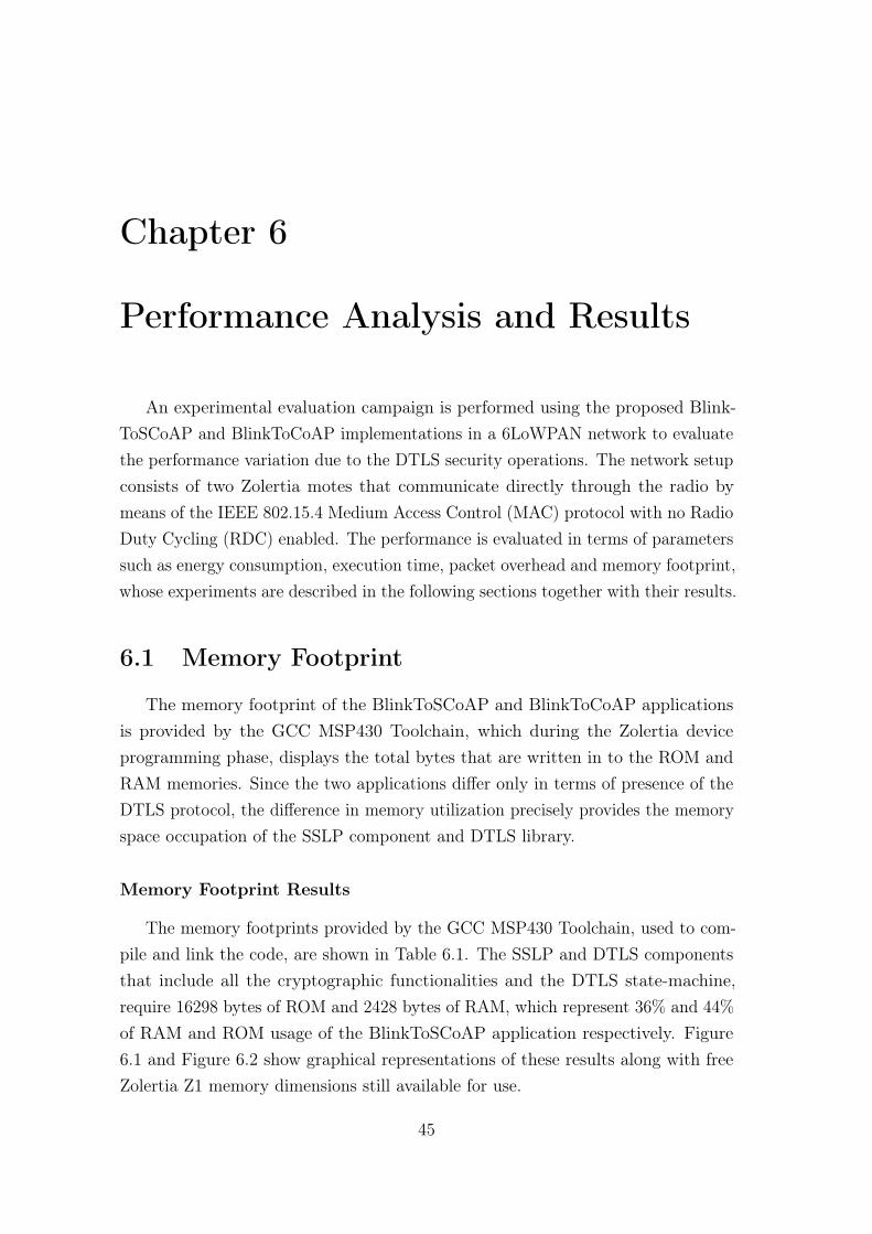
Chapter 6
Performance Analysis and Results
An experimental evaluation campaign is performed using the proposed Blink-ToSCoAP and BlinkToCoAP implementations in a 6LoWPAN network to evaluatethe performance variation due to the DTLS security operations. The network setupconsists of two Zolertia motes that communicate directly through the radio bymeans of the IEEE 802.15.4 Medium Access Control (MAC) protocol with no RadioDuty Cycling (RDC) enabled. The performance is evaluated in terms of parameterssuch as energy consumption, execution time, packet overhead and memory footprint,whose experiments are described in the following sections together with their results.
6.1 Memory Footprint
The memory footprint of the BlinkToSCoAP and BlinkToCoAP applicationsis provided by the GCC MSP430 Toolchain, which during the Zolertia deviceprogramming phase, displays the total bytes that are written in to the ROM andRAM memories. Since the two applications differ only in terms of presence of theDTLS protocol, the difference in memory utilization precisely provides the memoryspace occupation of the SSLP component and DTLS library.
Memory Footprint Results
The memory footprints provided by the GCC MSP430 Toolchain, used to com-pile and link the code, are shown in Table 6.1. The SSLP and DTLS componentsthat include all the cryptographic functionalities and the DTLS state-machine,require 16298 bytes of ROM and 2428 bytes of RAM, which represent 36% and 44%of RAM and ROM usage of the BlinkToSCoAP application respectively. Figure6.1 and Figure 6.2 show graphical representations of these results along with freeZolertia Z1 memory dimensions still available for use.
45
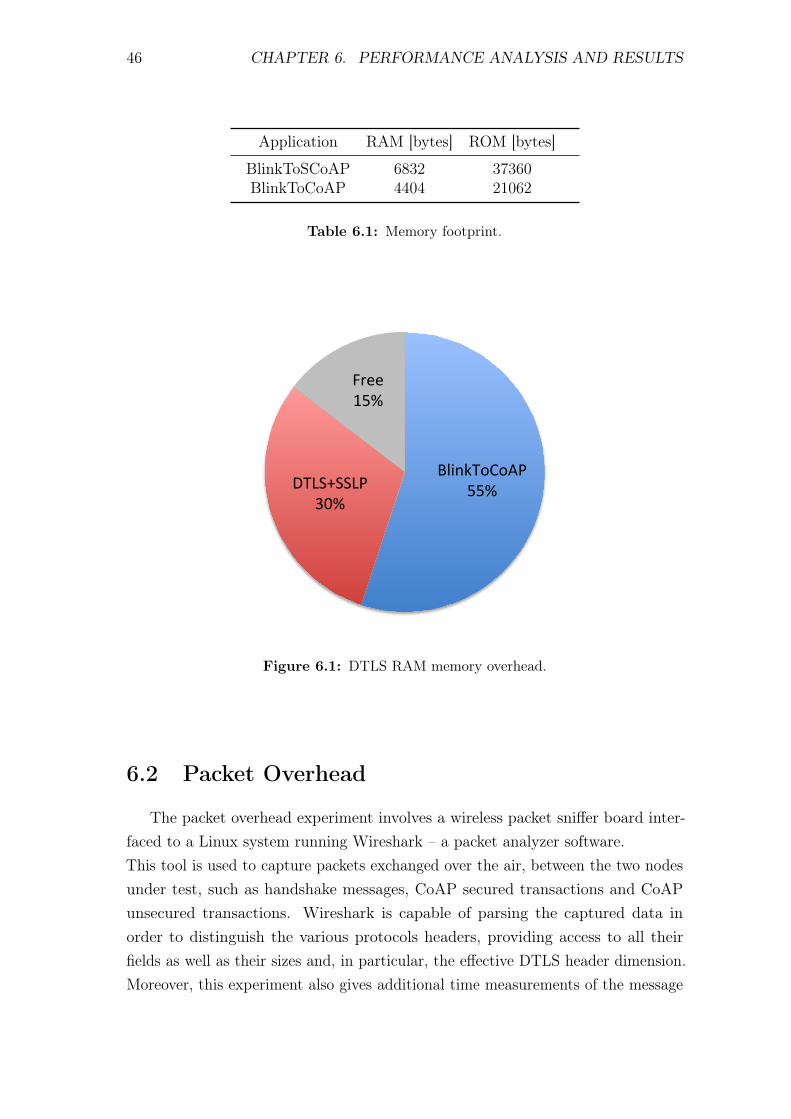
46 CHAPTER 6. PERFORMANCE ANALYSIS AND RESULTS
Application RAM [bytes] ROM [bytes]
BlinkToSCoAP 6832 37360BlinkToCoAP 4404 21062
Table 6.1: Memory footprint.
BlinkToCoAP+55%+DTLS+SSLP+
30%+
Free+15%+
Figure 6.1: DTLS RAM memory overhead.
6.2 Packet Overhead
The packet overhead experiment involves a wireless packet sniffer board inter-faced to a Linux system running Wireshark – a packet analyzer software.This tool is used to capture packets exchanged over the air, between the two nodesunder test, such as handshake messages, CoAP secured transactions and CoAPunsecured transactions. Wireshark is capable of parsing the captured data inorder to distinguish the various protocols headers, providing access to all theirfields as well as their sizes and, in particular, the effective DTLS header dimension.Moreover, this experiment also gives additional time measurements of the message
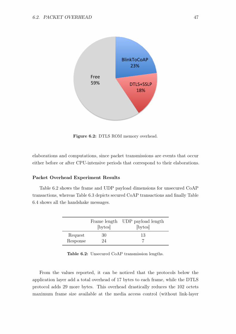
6.2. PACKET OVERHEAD 47
BlinkToCoAP+23%+
DTLS+SSLP+18%+
Free+59%+
Figure 6.2: DTLS ROM memory overhead.
elaborations and computations, since packet transmissions are events that occureither before or after CPU-intensive periods that correspond to their elaborations.
Packet Overhead Experiment Results
Table 6.2 shows the frame and UDP payload dimensions for unsecured CoAPtransactions, whereas Table 6.3 depicts secured CoAP transactions and finally Table6.4 shows all the handshake messages.
Frame length UDP payload length[bytes] [bytes]
Request 30 13Response 24 7
Table 6.2: Unsecured CoAP transmission lengths.
From the values reported, it can be noticed that the protocols below theapplication layer add a total overhead of 17 bytes to each frame, while the DTLSprotocol adds 29 more bytes. This overhead drastically reduces the 102 octetsmaximum frame size available at the media access control (without link-layer
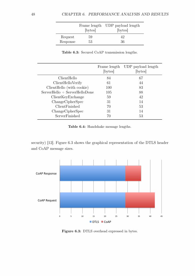
48 CHAPTER 6. PERFORMANCE ANALYSIS AND RESULTS
Frame length UDP payload length[bytes] [bytes]
Request 59 42Response 53 36
Table 6.3: Secured CoAP transmission lengths.
Frame length UDP payload length[bytes] [bytes]
ClientHello 84 67ClientHelloVerify 61 44
ClientHello (with cookie) 100 83ServerHello + ServerHelloDone 105 88
ClientKeyExchange 59 42ChangeCipherSpec 31 14ClientFinished 70 53
ChangeCipherSpec 31 14ServerFinished 70 53
Table 6.4: Handshake message lengths.
security) [12]. Figure 6.3 shows the graphical representation of the DTLS headerand CoAP message sizes.
0" 5" 10" 15" 20" 25" 30" 35" 40" 45"
CoAP"Request"
CoAP"Response"
DTLS" CoAP"
Figure 6.3: DTLS overhead expressed in bytes.
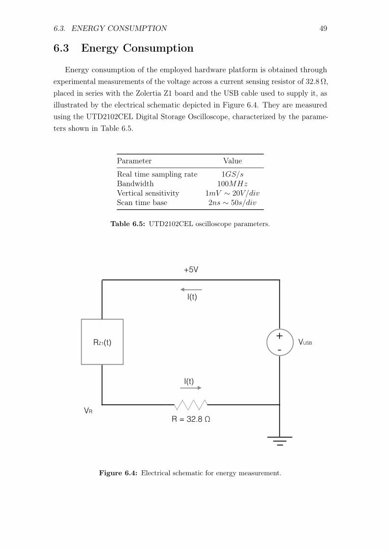
6.3. ENERGY CONSUMPTION 49
6.3 Energy Consumption
Energy consumption of the employed hardware platform is obtained throughexperimental measurements of the voltage across a current sensing resistor of 32.8 Ω,placed in series with the Zolertia Z1 board and the USB cable used to supply it, asillustrated by the electrical schematic depicted in Figure 6.4. They are measuredusing the UTD2102CEL Digital Storage Oscilloscope, characterized by the parame-ters shown in Table 6.5.
Parameter Value
Real time sampling rate 1GS/sBandwidth 100MHzVertical sensitivity 1mV ∼ 20V/divScan time base 2ns ∼ 50s/div
Table 6.5: UTD2102CEL oscilloscope parameters.
R = 32.8 Ω
+5V
RZ1(t)+ -
VUSB
I(t)
VR
I(t)
Figure 6.4: Electrical schematic for energy measurement.
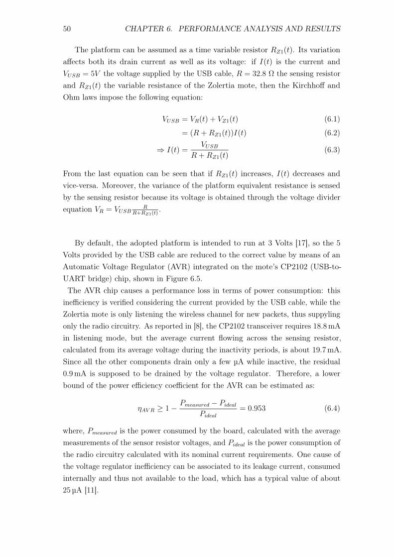
50 CHAPTER 6. PERFORMANCE ANALYSIS AND RESULTS
The platform can be assumed as a time variable resistor RZ1(t). Its variationaffects both its drain current as well as its voltage: if I(t) is the current andVUSB = 5V the voltage supplied by the USB cable, R = 32.8 Ω the sensing resistorand RZ1(t) the variable resistance of the Zolertia mote, then the Kirchhoff andOhm laws impose the following equation:
VUSB = VR(t) + VZ1(t) (6.1)
= (R +RZ1(t))I(t) (6.2)
⇒ I(t) =VUSB
R +RZ1(t)(6.3)
From the last equation can be seen that if RZ1(t) increases, I(t) decreases andvice-versa. Moreover, the variance of the platform equivalent resistance is sensedby the sensing resistor because its voltage is obtained through the voltage dividerequation VR = VUSB
RR+RZ1(t)
.
By default, the adopted platform is intended to run at 3 Volts [17], so the 5Volts provided by the USB cable are reduced to the correct value by means of anAutomatic Voltage Regulator (AVR) integrated on the mote’s CP2102 (USB-to-UART bridge) chip, shown in Figure 6.5.The AVR chip causes a performance loss in terms of power consumption: this
inefficiency is verified considering the current provided by the USB cable, while theZolertia mote is only listening the wireless channel for new packets, thus suppylingonly the radio circuitry. As reported in [8], the CP2102 transceiver requires 18.8mAin listening mode, but the average current flowing across the sensing resistor,calculated from its average voltage during the inactivity periods, is about 19.7mA.Since all the other components drain only a few µA while inactive, the residual0.9mA is supposed to be drained by the voltage regulator. Therefore, a lowerbound of the power efficiency coefficient for the AVR can be estimated as:
ηAV R ≥ 1− Pmeasured − Pideal
Pideal
= 0.953 (6.4)
where, Pmeasured is the power consumed by the board, calculated with the averagemeasurements of the sensor resistor voltages, and Pideal is the power consumption ofthe radio circuitry calculated with its nominal current requirements. One cause ofthe voltage regulator inefficiency can be associated to its leakage current, consumedinternally and thus not available to the load, which has a typical value of about25 µA [11].
6.3. ENERGY CONSUMPTION 51
R = 32.8 Ω
+ -
GND
OUT IN
AVR
+5V+3V
RINT,Z1(t) VUSB
I(t)
ILEAK
IINT,Z1(t)
VR
I(t)
Figure 6.5: Energy experiment electrical schematic with AVR.
The AVR chip inefficiencies thus slightly increment the energy consumption ofthe Zolertia nodes. However, since the performance evaluation is focused on theimpact of the DTLS operations on response time and energy consumption, thisperformance loss due to the AVR chip will not affect the evaluation of the higherenergy requirements of BlinkToSCoAP with respect to BlinkToCoAP. For thisreason this issue will be neglected in the following considerations and the estimationof the Zolertia Z1 energy consumption, for a given operation of duration T , iscalculated as:
EZ1 = PZ1T (6.5)
= VZ1IT (6.6)
= (VUSB − VR)VRRT (6.7)
where, Ediss,Z1 and Pdiss,Z1 are respectively the energy and the power dissipated bythe hardware platform.
The experiment is subdivided into three subsections, each of them involving adifferent communication mode:
• CoAP secured and unsecured transmissions;
52 CHAPTER 6. PERFORMANCE ANALYSIS AND RESULTS
• DTLS handshake phases.
CoAP Secured and Unsecured Transmissions
In this experiment the two nodes have already established a secure channel bymeans of the DTLS Handshake Protocol. The first goal to achieve is to understandthe time behaviour of the resistor voltage: theoretically, the client mote activityshould be represented on the oscilloscope behaviour as a step, caused by theincremented power need of the Zolertia platform due to the request elaborationand transmission, followed by a certain period of inactivity time where the mote isawaiting the server response and another step that signals the request receipt andelaboration. In a complementary manner, the oscilloscope sensing the server node’sactivity should display an unique step due to the request reception and elaborationas well as the response computation and transmission.In order to evidence DTLS operations, the SSLP component is configured, for thisexperiment, to turn on a LED every time the DTLS module is called to handle amessage, involving operations such as encryption, decryption, message computationand message parsing. When the security operations are signaled as concluded, theLED is turned off. Furthermore, while the first probe of the oscilloscope senses thevoltage of the sensing resistor, the second one measures the activity of the togglingdiode. The behaviour displayed by the electrical tool for a secured transmissionwhile studying a CoAP client is shown in Figure 6.6.
The measurements in yellow indicate LED activity: the steps correspond to theCPU time used by the DTLS library for its security operations. Moreover, re-quest transmission and response receipt are clearly visible on the blue samplesthat indicate the first oscilloscope probe measures. The security calculations areevidenced by both the diode activity as well as its energy consumption, noticeableon the blue samples as a second step over the main one, which instead indicatesthe high CPU utilization. The resistor voltage also shows the particular Tx and Rxoperations, recognized as two consecutive troughs clearly visible after the elabo-ration of the packet to send and also present – in a less clear form – just beforeresponse elaboration. Between the elaboration of the CoAP request and its trans-mission, it is also possible to recognize the fraction of time where the radio circuitryof the Zolertia mote is sensing the wireless channel in order to avoid packet collisions.
The same experiment, applied to the CoAP server mote, yields the behaviourdepicted in Figure 6.7, which clearly evidences the CPU time phases belonging to
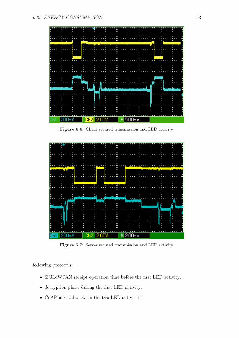
6.3. ENERGY CONSUMPTION 53
Figure 6.6: Client secured transmission and LED activity.
Figure 6.7: Server secured transmission and LED activity.
following protocols:
• SiGLoWPAN receipt operation time before the first LED activity;
• decryption phase during the first LED activity;
• CoAP interval between the two LED activities;
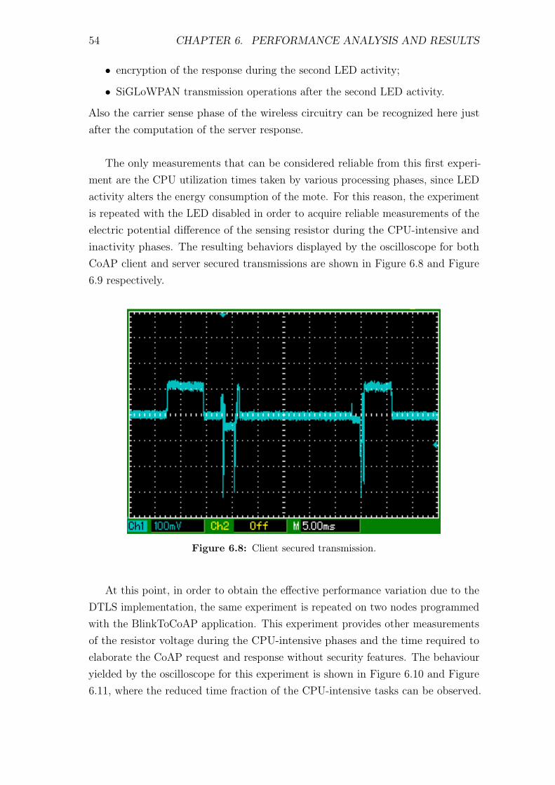
54 CHAPTER 6. PERFORMANCE ANALYSIS AND RESULTS
• encryption of the response during the second LED activity;
• SiGLoWPAN transmission operations after the second LED activity.
Also the carrier sense phase of the wireless circuitry can be recognized here justafter the computation of the server response.
The only measurements that can be considered reliable from this first experi-ment are the CPU utilization times taken by various processing phases, since LEDactivity alters the energy consumption of the mote. For this reason, the experimentis repeated with the LED disabled in order to acquire reliable measurements of theelectric potential difference of the sensing resistor during the CPU-intensive andinactivity phases. The resulting behaviors displayed by the oscilloscope for bothCoAP client and server secured transmissions are shown in Figure 6.8 and Figure6.9 respectively.
Figure 6.8: Client secured transmission.
At this point, in order to obtain the effective performance variation due to theDTLS implementation, the same experiment is repeated on two nodes programmedwith the BlinkToCoAP application. This experiment provides other measurementsof the resistor voltage during the CPU-intensive phases and the time required toelaborate the CoAP request and response without security features. The behaviouryielded by the oscilloscope for this experiment is shown in Figure 6.10 and Figure6.11, where the reduced time fraction of the CPU-intensive tasks can be observed.
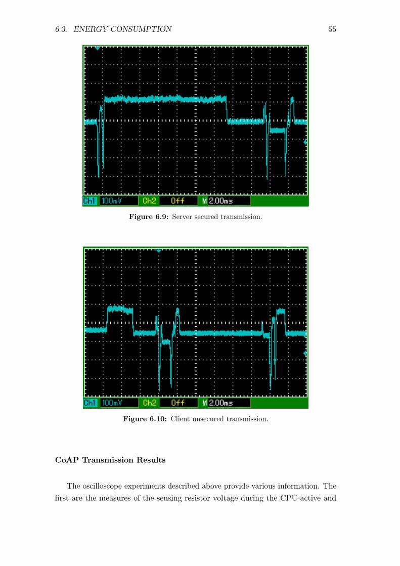
6.3. ENERGY CONSUMPTION 55
Figure 6.9: Server secured transmission.
Figure 6.10: Client unsecured transmission.
CoAP Transmission Results
The oscilloscope experiments described above provide various information. Thefirst are the measures of the sensing resistor voltage during the CPU-active and
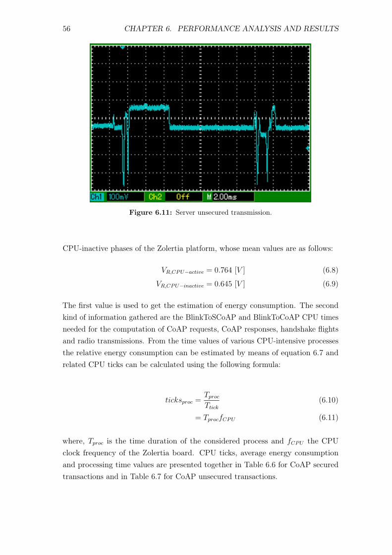
56 CHAPTER 6. PERFORMANCE ANALYSIS AND RESULTS
Figure 6.11: Server unsecured transmission.
CPU-inactive phases of the Zolertia platform, whose mean values are as follows:
VR,CPU−active = 0.764 [V ] (6.8)
VR,CPU−inactive = 0.645 [V ] (6.9)
The first value is used to get the estimation of energy consumption. The secondkind of information gathered are the BlinkToSCoAP and BlinkToCoAP CPU timesneeded for the computation of CoAP requests, CoAP responses, handshake flightsand radio transmissions. From the time values of various CPU-intensive processesthe relative energy consumption can be estimated by means of equation 6.7 andrelated CPU ticks can be calculated using the following formula:
ticksproc =TprocTtick
(6.10)
= TprocfCPU (6.11)
where, Tproc is the time duration of the considered process and fCPU the CPUclock frequency of the Zolertia board. CPU ticks, average energy consumptionand processing time values are presented together in Table 6.6 for CoAP securedtransactions and in Table 6.7 for CoAP unsecured transactions.
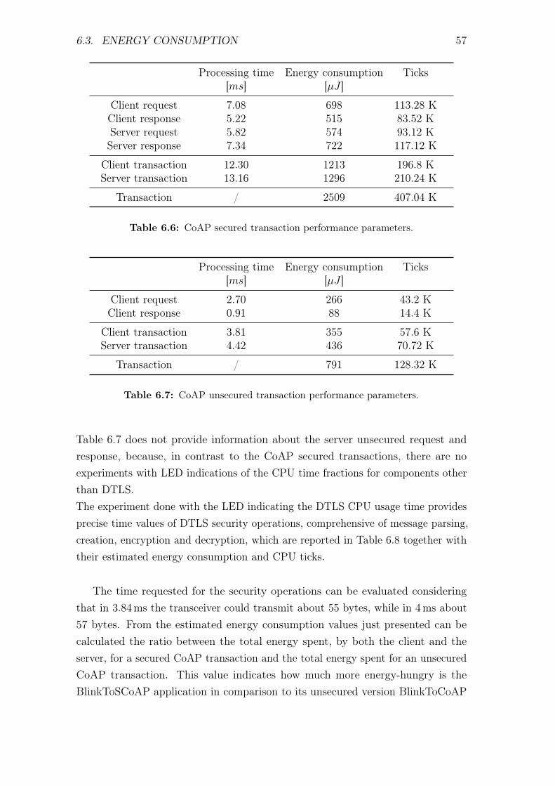
6.3. ENERGY CONSUMPTION 57
Processing time Energy consumption Ticks[ms] [µJ ]
Client request 7.08 698 113.28 KClient response 5.22 515 83.52 KServer request 5.82 574 93.12 KServer response 7.34 722 117.12 K
Client transaction 12.30 1213 196.8 KServer transaction 13.16 1296 210.24 K
Transaction / 2509 407.04 K
Table 6.6: CoAP secured transaction performance parameters.
Processing time Energy consumption Ticks[ms] [µJ ]
Client request 2.70 266 43.2 KClient response 0.91 88 14.4 K
Client transaction 3.81 355 57.6 KServer transaction 4.42 436 70.72 K
Transaction / 791 128.32 K
Table 6.7: CoAP unsecured transaction performance parameters.
Table 6.7 does not provide information about the server unsecured request andresponse, because, in contrast to the CoAP secured transactions, there are noexperiments with LED indications of the CPU time fractions for components otherthan DTLS.The experiment done with the LED indicating the DTLS CPU usage time providesprecise time values of DTLS security operations, comprehensive of message parsing,creation, encryption and decryption, which are reported in Table 6.8 together withtheir estimated energy consumption and CPU ticks.
The time requested for the security operations can be evaluated consideringthat in 3.84ms the transceiver could transmit about 55 bytes, while in 4ms about57 bytes. From the estimated energy consumption values just presented can becalculated the ratio between the total energy spent, by both the client and theserver, for a secured CoAP transaction and the total energy spent for an unsecuredCoAP transaction. This value indicates how much more energy-hungry is theBlinkToSCoAP application in comparison to its unsecured version BlinkToCoAP
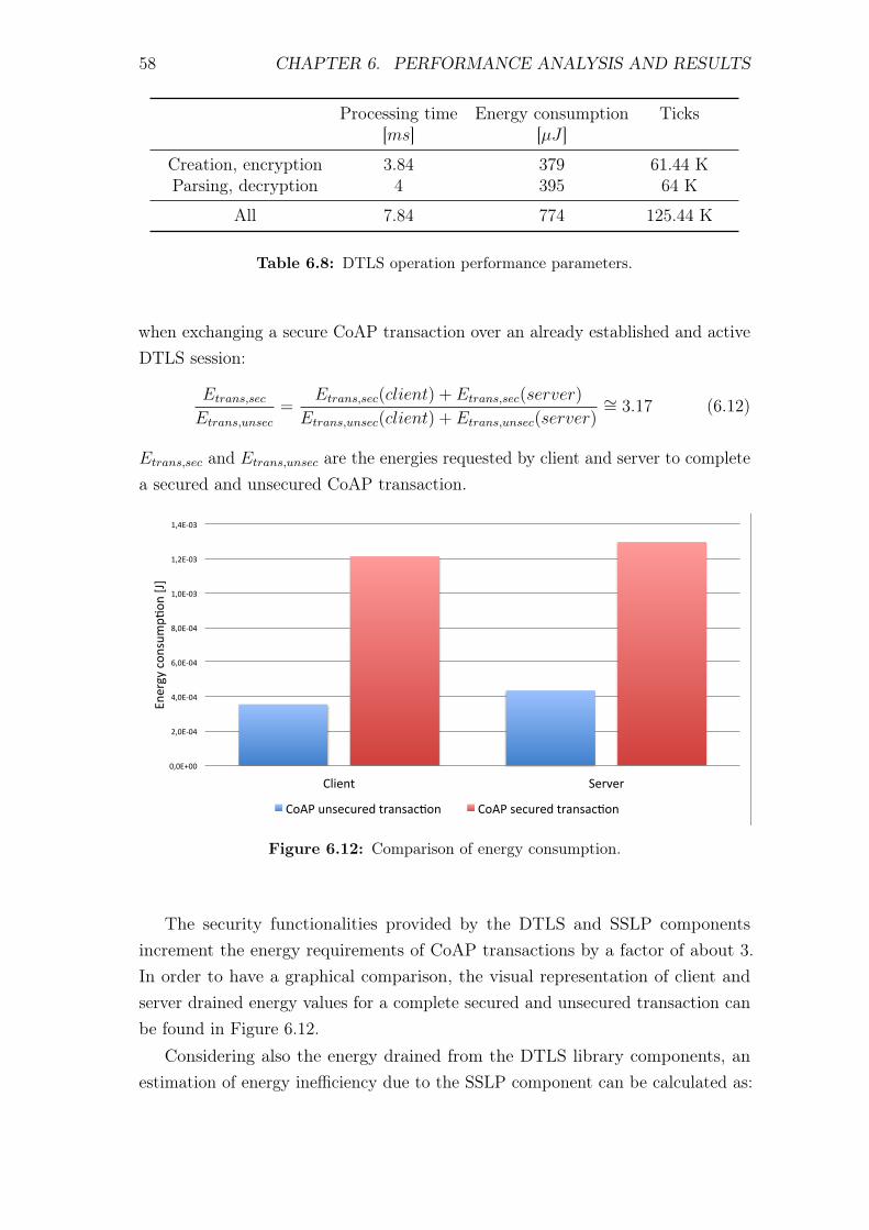
58 CHAPTER 6. PERFORMANCE ANALYSIS AND RESULTS
Processing time Energy consumption Ticks[ms] [µJ ]
Creation, encryption 3.84 379 61.44 KParsing, decryption 4 395 64 K
All 7.84 774 125.44 K
Table 6.8: DTLS operation performance parameters.
when exchanging a secure CoAP transaction over an already established and activeDTLS session:
Etrans,sec
Etrans,unsec
=Etrans,sec(client) + Etrans,sec(server)
Etrans,unsec(client) + Etrans,unsec(server)∼= 3.17 (6.12)
Etrans,sec and Etrans,unsec are the energies requested by client and server to completea secured and unsecured CoAP transaction.
0,0E+00%
2,0E'04%
4,0E'04%
6,0E'04%
8,0E'04%
1,0E'03%
1,2E'03%
1,4E'03%
Client% Server%
Energy%con
sump>
on%[J]%
CoAP%unsecured%transac>on% CoAP%secured%transac>on%
Figure 6.12: Comparison of energy consumption.
The security functionalities provided by the DTLS and SSLP componentsincrement the energy requirements of CoAP transactions by a factor of about 3.In order to have a graphical comparison, the visual representation of client andserver drained energy values for a complete secured and unsecured transaction canbe found in Figure 6.12.
Considering also the energy drained from the DTLS library components, anestimation of energy inefficiency due to the SSLP component can be calculated as:
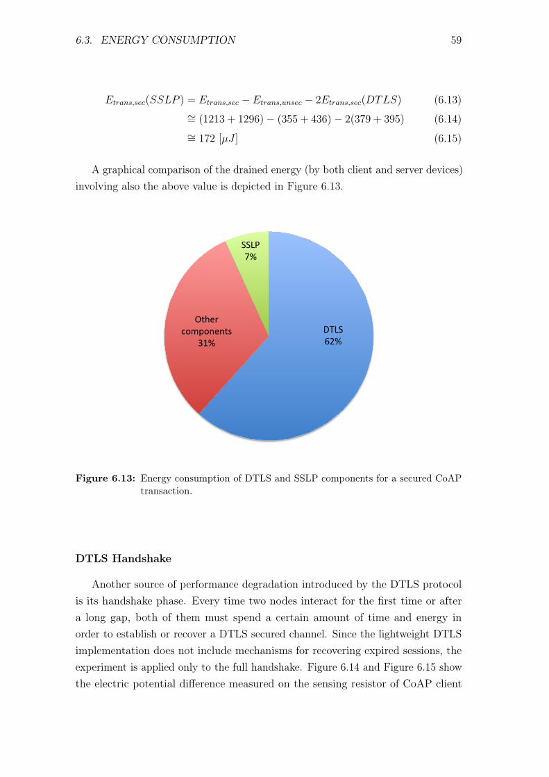
6.3. ENERGY CONSUMPTION 59
Etrans,sec(SSLP ) = Etrans,sec − Etrans,unsec − 2Etrans,sec(DTLS) (6.13)∼= (1213 + 1296)− (355 + 436)− 2(379 + 395) (6.14)∼= 172 [µJ ] (6.15)
A graphical comparison of the drained energy (by both client and server devices)involving also the above value is depicted in Figure 6.13.
DTLS%62%%
Other%components%
31%%
SSLP%7%%
Figure 6.13: Energy consumption of DTLS and SSLP components for a secured CoAPtransaction.
DTLS Handshake
Another source of performance degradation introduced by the DTLS protocolis its handshake phase. Every time two nodes interact for the first time or aftera long gap, both of them must spend a certain amount of time and energy inorder to establish or recover a DTLS secured channel. Since the lightweight DTLSimplementation does not include mechanisms for recovering expired sessions, theexperiment is applied only to the full handshake. Figure 6.14 and Figure 6.15 showthe electric potential difference measured on the sensing resistor of CoAP client
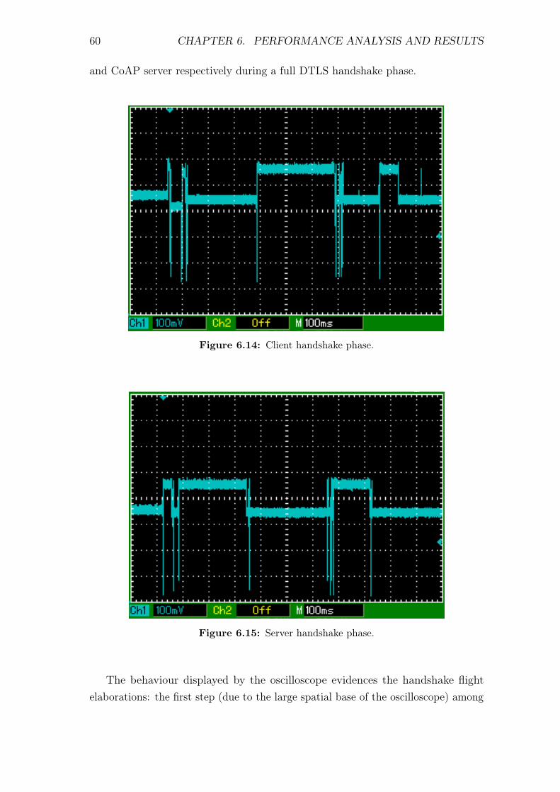
60 CHAPTER 6. PERFORMANCE ANALYSIS AND RESULTS
and CoAP server respectively during a full DTLS handshake phase.
Figure 6.14: Client handshake phase.
Figure 6.15: Server handshake phase.
The behaviour displayed by the oscilloscope evidences the handshake flightelaborations: the first step (due to the large spatial base of the oscilloscope) among
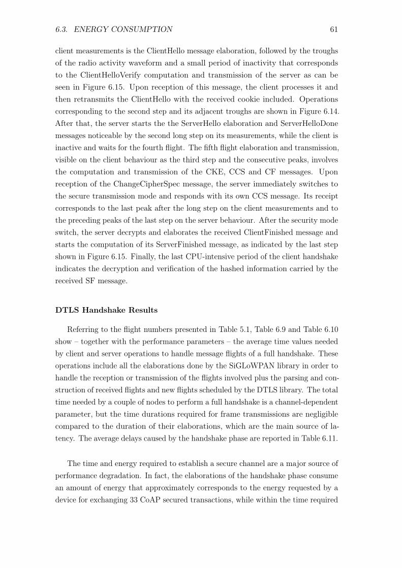
6.3. ENERGY CONSUMPTION 61
client measurements is the ClientHello message elaboration, followed by the troughsof the radio activity waveform and a small period of inactivity that correspondsto the ClientHelloVerify computation and transmission of the server as can beseen in Figure 6.15. Upon reception of this message, the client processes it andthen retransmits the ClientHello with the received cookie included. Operationscorresponding to the second step and its adjacent troughs are shown in Figure 6.14.After that, the server starts the the ServerHello elaboration and ServerHelloDonemessages noticeable by the second long step on its measurements, while the client isinactive and waits for the fourth flight. The fifth flight elaboration and transmission,visible on the client behaviour as the third step and the consecutive peaks, involvesthe computation and transmission of the CKE, CCS and CF messages. Uponreception of the ChangeCipherSpec message, the server immediately switches tothe secure transmission mode and responds with its own CCS message. Its receiptcorresponds to the last peak after the long step on the client measurements and tothe preceding peaks of the last step on the server behaviour. After the security modeswitch, the server decrypts and elaborates the received ClientFinished message andstarts the computation of its ServerFinished message, as indicated by the last stepshown in Figure 6.15. Finally, the last CPU-intensive period of the client handshakeindicates the decryption and verification of the hashed information carried by thereceived SF message.
DTLS Handshake Results
Referring to the flight numbers presented in Table 5.1, Table 6.9 and Table 6.10show – together with the performance parameters – the average time values neededby client and server operations to handle message flights of a full handshake. Theseoperations include all the elaborations done by the SiGLoWPAN library in order tohandle the reception or transmission of the flights involved plus the parsing and con-struction of received flights and new flights scheduled by the DTLS library. The totaltime needed by a couple of nodes to perform a full handshake is a channel-dependentparameter, but the time durations required for frame transmissions are negligiblecompared to the duration of their elaborations, which are the main source of la-tency. The average delays caused by the handshake phase are reported in Table 6.11.
The time and energy required to establish a secure channel are a major source ofperformance degradation. In fact, the elaborations of the handshake phase consumean amount of energy that approximately corresponds to the energy requested by adevice for exchanging 33 CoAP secured transactions, while within the time required
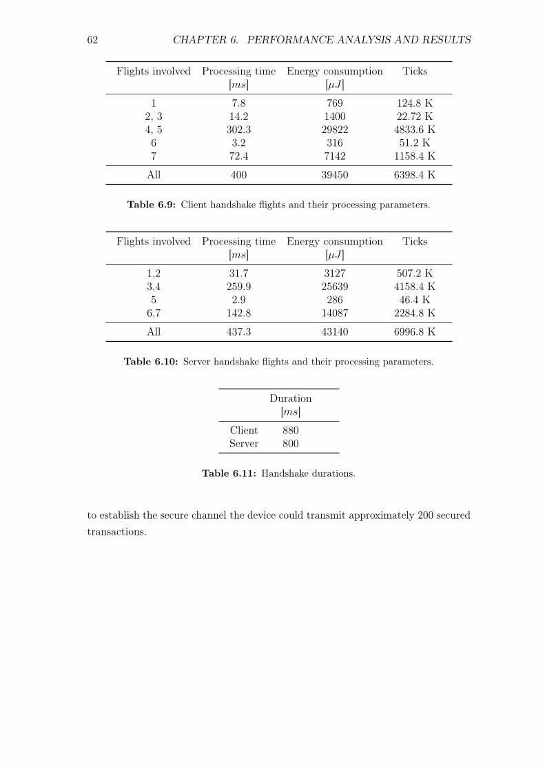
62 CHAPTER 6. PERFORMANCE ANALYSIS AND RESULTS
Flights involved Processing time Energy consumption Ticks[ms] [µJ ]
1 7.8 769 124.8 K2, 3 14.2 1400 22.72 K4, 5 302.3 29822 4833.6 K6 3.2 316 51.2 K7 72.4 7142 1158.4 K
All 400 39450 6398.4 K
Table 6.9: Client handshake flights and their processing parameters.
Flights involved Processing time Energy consumption Ticks[ms] [µJ ]
1,2 31.7 3127 507.2 K3,4 259.9 25639 4158.4 K5 2.9 286 46.4 K6,7 142.8 14087 2284.8 K
All 437.3 43140 6996.8 K
Table 6.10: Server handshake flights and their processing parameters.
Duration[ms]
Client 880Server 800
Table 6.11: Handshake durations.
to establish the secure channel the device could transmit approximately 200 securedtransactions.
Chapter 7
Conclusions
7.1 Concluding Remarks
The goal of this thesis was to present both the implementation as well asthe evaluation of a CoAP application secured by DTLS for 6LoWPAN-based IoTnetworks. This work gives an overview of the underlying protocol implementationsand new components merged to assemble the proposed BlinkToSCoAP applicationand outlines their relationships to ensure their correct collaboration. Experimentalresults show that despite the unoptimized state of protocols implementation andthe high number of their functionalities, the amount of RAM available in theZolertia Z1 platform is quite sufficient to contain all the necessary data. On theother hand, the security operations of DTLS implementation, consume considerableamounts of energy and introduce delay for every handshake carried out everytime two nodes begin a new communication or need to recover an expired session.Once the security session has been established, the security operations increasethe energy consumption of CoAP transmissions by a factor of about 3.2 and affectthe responsiveness of the nodes, which have to work for additional 8 millisecondsper CoAP transaction in order to deal with obfuscated data and to transmit theadditional DTLS header.The context considered to assess the quality of the proposed application comprisescommunications between only two devices supplied through a USB cable. Therefore,the next logical step would be the evaluation of the application performance inmore realistic conditions involving multiple nodes running on battery supply.
63
64 CHAPTER 7. CONCLUSIONS
7.2 Future Work
The development of the BlinkToSCoAP application and its performance evalua-tion has raised some issues that suggest possible directions for future work as anextension of the works presented here.
Delegation of the handshake operations The operations done during the hand-shake phase cause a considerable amount of energy consumption and latency.A future work could analyze the possibility to delegate these operations to atrusted third entity with no energy constraint and with better performance,reducing the delay and allowing the devices to save precious energy.
Dynamic memory approach The MemoryManager component included in theSiGLoWPAN library provides functionalities that greatly simplify and opti-mize the memory management for constrained devices. Reviewing the CoAPand DTLS libraries, in order to change their static allocation approach tothe dynamic one by the MemoryManager module, can greatly improve theapplication performance while also reducing source code complexity andincrementing code reutilization.
DTLS vertical orientation The SSLP solution, presented in Chapter 5, thatresolves the issues of the DTLS horizontal design may not be the best one. Abetter alternative would be to rewrite the DTLS interface. This operationfirstly will remove the DTLS structures from the signatures of the interfaceprimitives, forcing the dtls module to keep its variables private. Secondly, itwill replace the events used to signal obfuscated or plain data just after itselaboration with events that signal the transmission of the current messageor the receipt of a new one. The rewriting process then would also involvethe dtls component that has to include the mechanisms implemented in theSSLP module in order to handle the transmission and receipt of packets viathe UDP interface provided by the SiGLoWPAN library.
TimedPool for handshake reliability The TimedPool component included inthe CoAP library implements a timed queue intended to provide CoAPmessage reliability. This module could also be exploited by the DTLS libraryin order to guard against handshake message losses, while also incrementingthe source code reutilization.
CoAP separated responses The current implementation of the CoAP protocoldoes not provide separate responses for confirmable messages. This means
7.2. FUTURE WORK 65
that if the server needs more than a CoAP timeout duration to elaborate theresponse, the client will retransmit the request, thus wasting precious energyand network resources. Therefore, the implementation of CoAP separatedresponses could enhance the overall application performance. This feature alsoraises the need for a second matching mechanism, that has to be implementedas well, in order to have a distinct identifier for CoAP CON, NON, ACKmessages and CoAP requests and responses.
DTLS header compression Experimental results show that the DTLS protocoladds 29 bytes of header to each CoAP message. In order to enhance boththe transmission efficiency as well as the maximum payload size availablewithout MAC layer fragmentation, the 6LoWPAN header compression forDTLS presented in [13] could be integrated into the SiGLoWPAN library.

Bibliography
[1] 2013. url: http : / / www . eetutorials . com / article / 28 / 1 / TinyOS -
installation-guide-on-Ubuntu.html (cit. on p. 25).
[2] C. Bormann. Using CoAP with IPsec. Tech. rep. CoRE Working Group, 2012(cit. on p. 2).
[3] A. Castellani, G. Ministeri, M. Rotoloni, L. Vangelista, and M. Zorzi. “Inter-operable and globally interconnected Smart Grid using IPv6 and 6LoWPAN”.In: Communications (ICC), 2012 IEEE International Conference on. 2012,pp. 6473–6478 (cit. on pp. 30, 32).
[4] T. Dierks and E. Rescorla. The Transport Layer Security (TLS) ProtocolVersion 1.2. RFC 5246 (Proposed Standard). Updated by RFCs 5746, 5878,6176. Internet Engineering Task Force, Aug. 2008. url: http://www.ietf.org/rfc/rfc5246.txt (cit. on p. 13).
[5] R. T. Fielding. “REST: Architectural Styles and the Design of Network-basedSoftware Architectures”. Doctoral dissertation. University of California, Irvine,2000. url: http://www.ics.uci.edu/~fielding/pubs/dissertation/top.htm (cit. on p. 5).
[6] J. Granjal, E. Monteiro, and J. Sa Silva. “On the feasibility of secureapplication-layer communications on the Web of Things”. In: Local Com-puter Networks (LCN), 2012 IEEE 37th Conference on. 2012, pp. 228–231(cit. on p. 3).
[7] J. Granjal, E. Monteiro, and J. Silva. “On the Effectiveness of End-to-EndSecurity for Internet-Integrated Sensing Applications”. In: Green Computingand Communications (GreenCom), 2012 IEEE International Conference on.2012, pp. 87–93 (cit. on p. 3).
[8] T. Instruments. CC2420 Datasheet. url: http://www.silabs.com/Support%20Documents/TechnicalDocs/CP2102-9.pdf (cit. on p. 50).
[9] A. Kevin. “That ’Internet of Things’ Thing, in the real world things mattermore than ideas”. In: RFID Journal (2009) (cit. on p. 1).
67
68 BIBLIOGRAPHY
[10] T. Kothmayr, C. Schmitt, W. Hu, M. Brunig, and G. Carle. “A DTLS basedend-to-end security architecture for the Internet of Things with two-wayauthentication”. In: Local Computer Networks Workshops (LCN Workshops),2012 IEEE 37th Conference on. 2012, pp. 956–963 (cit. on p. 3).
[11] S. Labs. CP2102 Datasheet. url: http://www.silabs.com/Support%20Documents/TechnicalDocs/CP2102-9.pdf (cit. on p. 50).
[12] G. Montenegro, N. Kushalnagar, J. Hui, and D. Culler. Transmission ofIPv6 Packets over IEEE 802.15.4 Networks. RFC 4944 (Proposed Standard).Updated by RFCs 6775, 6282. Internet Engineering Task Force, 2007. url:https://datatracker.ietf.org/doc/rfc4944/ (cit. on p. 48).
[13] S. Raza, D. Trabalza, and T. Voigt. “6LoWPAN Compressed DTLS forCoAP”. In: Distributed Computing in Sensor Systems (DCOSS), 2012 IEEE8th International Conference on. 2012, pp. 287–289 (cit. on pp. 4, 65).
[14] S. Raza, H. Shafagh, K. Hewage, R. Hummen, and T. Voigt. “Lithe: LightweightSecure CoAP for the Internet of Things”. In: Sensors Journal, IEEE 13.10(2013), pp. 3711–3720 (cit. on p. 4).
[15] E. Rescorla and N. Modadugu. Datagram Transport Layer Security. RFC4347 (Proposed Standard). Updated by RFC 5746. Internet Engineering TaskForce, Apr. 2006. url: http://www.ietf.org/rfc/rfc4347.txt (cit. onpp. 2, 13, 18).
[16] Z. Shelby, Sensinode, K. Hartke, and C. Bormann. Constrained ApplicationProtocol (CoAP) draft-ietf-core-coap-18. Tech. rep. CoRE Working Group,2013 (cit. on pp. 2, 5).
[17] Zolertia. Z1 Datasheet. 2013. url: http://zolertia.sourceforge.net/wiki/images/e/e8/Z1_RevC_Datasheet.pdf (cit. on p. 50).


![Security analysis of DTLS 1.2 implementations€¦ · To secure UDP tra c, Datagram Transport Layer Security (DTLS) has been published [5] [6] [7]. DTLS is a security protocol based](https://static.fdocuments.us/doc/165x107/5e9fdce701388322847d1ed4/security-analysis-of-dtls-12-implementations-to-secure-udp-tra-c-datagram-transport.jpg)