CO2 Capture Retrofit Issues IGCC Technical Discussion · • Establish Tie-ins during Short-Term...
40
1 CO 2 Capture Retrofit Issues IGCC Technical Discussion Dan Kubek (Gas Processing Solutions LLC) Chris Higman (Syngas Consultants Ltd) Neville Holt (EPRI) Ron Schoff (EPRI) Gasification Technologies 2007 October 16, 2007 San Francisco, CA
Transcript of CO2 Capture Retrofit Issues IGCC Technical Discussion · • Establish Tie-ins during Short-Term...

1
CO2 Capture Retrofit IssuesIGCC Technical Discussion
Dan Kubek (Gas Processing Solutions LLC)Chris Higman (Syngas Consultants Ltd)Neville Holt (EPRI) Ron Schoff (EPRI)
Gasification Technologies 2007October 16, 2007San Francisco, CA

2© 2007 Electric Power Research Institute, Inc. All rights reserved.
IGCC Plants & CO2 Capture Issue:Progression of Thinking
• <2004– Limited Discussion of Subject
• 2004–2006– Grassroots with CO2 Capture
• Defined Designs• Significant Interest
• 2007– IGCC Plants Operational w/ Deferred CO2 Capture Facilities
• Regulatory landscape undefined• CO2 pipeline transmission infrastructure and regulations• Sequestration or enhanced oil recovery sites

3© 2007 Electric Power Research Institute, Inc. All rights reserved.
Retrofitting IGCC for CO2 CapturePerception: Capture Ready
• IGCC Plants are CO2 Capture Ready (“Bolt-on”)
• Additions:– Add Two CO-(Water Gas) Shift Reactors– Add CO2 – Acid Gas Removal Section– Add CO2 Compressor
• Leave Sufficient Plot Space
• Construct when Needed while IGCC Plant Operational
• Establish Tie-ins during Short-Term Turnaround
• Some Parasitic Power Loss Due to Additions

4© 2007 Electric Power Research Institute, Inc. All rights reserved.
IGCC without CO2 Capture

5© 2007 Electric Power Research Institute, Inc. All rights reserved.
IGCC with CO2 Capture
CO2 Capture = Shift, CO2 Removal, H2 Firing, Space, $, Energy
New Additions

6© 2007 Electric Power Research Institute, Inc. All rights reserved.
Retrofitting IGCC for CO2 CaptureReality: Numerous Process Issues
• How Much CO2 Capture?
• How Much Pre-Investment?
• New CO-Shift– Sour or Sweet?– # of Reactors?
• Impact upon Acid Gas Removal Unit (AGRU) and Sulfur Recovery Unit (SRU)?– Existing H2S-AGRU Section– New CO2-AGRU Section– Existing SRU & Tail Gas Treating/Recycle
Compressor

7© 2007 Electric Power Research Institute, Inc. All rights reserved.
Retrofitting IGCC for CO2 CaptureReality: Numerous Process Issues (cont’d)
• CO2 Compression Route?
• CO2 Purity?
• Impact of Added Syngas Pressure Drop Prior to Gas Turbine?
• Hydrogen as Gas Turbine Fuel?
• Significant Reduction of Plant Power Output– Lower Gas Turbine Power Output– Reduction in Steam Available for Steam Turbine– Parasitic Power Loads (CO2-AGRU and CO2 Compression)
• Effect on ASU Size and Air Compression

8© 2007 Electric Power Research Institute, Inc. All rights reserved.
IGCC Pre-Investment Options for Later Addition of CO2 Capture
• Standard Provisions– Space for additional equipment, BOP, and site access at later date – Net power capacity, efficiency, and cost penalty upon conversion to capture
• Moderate Provisions– Additional ASU, gasification, and gas clean-up is needed to fully load the GTs
when shift is added – If this oversizing is included in the initial IGCC investment, the capacity can be
used in the pre-capture phase for supplemental firing or co-production– This version of “capture ready” would then permit full GT output with hydrogen
(at ISO) when capture is added. Mitigates the cost and efficiency penalty.
• Extensive Provisions– Design with conversion-shift reactors, oversized components, AGR absorber
sized for shifted syngas, but no CO2 absorber and compressor– No need for major shutdown to complete the conversion to CO2 capture

9© 2007 Electric Power Research Institute, Inc. All rights reserved.
Carbon Capture Capability
“The term ‘carbon capture capability’ means a gasification plant design which is determined by the Secretary to reflect reasonable consideration for, and be capable of,
accommodating the equipment likely to be necessary to capture carbon dioxide from the gaseous stream,for later use or sequestration, which would otherwise be emitted in the flue gas from a project which uses a nonrenewable fuel.”
US Energy Policy Act, 2005, Section 48B (5)

10© 2007 Electric Power Research Institute, Inc. All rights reserved.
How Much CO2 Capture (CCS) Is Required?
• ~ 20% CCS– Capture CO2 from Gasifier w/o CO-Shift – Not applicable to Dry Feed Gasifiers due to limited CO2-make
• ~ 50% CCS– Add 1 Stage of CO-Shift– Brings CO2 (lb-CO2/MWh) to the level of an (inefficient) NGCC
(California PUC “Emission Performance Standard” in response toSenate Bill 1368: 1100 lb-CO2/MWh)
• ~ 65% CCS– Add 1-stage of CO-Shift– Brings CO2 capture to ~800 lb-CO2/MWh for state-of-art NGCC
• ~ 90% CCS– Add 2 Stages of CO-Shift– Full Capture level often cited
CO2 capture level may be more politically than technically driven

11© 2007 Electric Power Research Institute, Inc. All rights reserved.
CO2 Capture Drivers
• Federal– Bills on the table in the Senate and House to reduce
carbon emissions over time (See Tom Wilson and Ben Yamagata presentations on Wednesday)
– Carbon tax (supported by Duke Energy and others)– Renewable Portfolio Standards
• State– California PUC interim emission performance standard
(now also adopted in Washington state)– Incentives: CO, IL, IN, KS, MN, NY, OH, PA, TX, WY– Emerging Action: KY, MS, NM, VA, WV
• Commercial– Enhanced oil recovery– Other industrial uses

12© 2007 Electric Power Research Institute, Inc. All rights reserved.
CO2 Capture: Gasification References and Experience
• IGCC and CO2 removal are both offered commercially, but have not operated in a mature integrated manner
• No coal-gasification-based Power Plant(IGCC) currently recovers CO2 from the process
• 3 U.S. non-power gasification facilities (Coffeyville, Eastman, and Great Plains) recover and compress CO2
• Numerous gasification-based ammonia plants in China and elsewhere recover and recompress CO2 for urea production
• Recovered CO2 from the Great Plains plant is used for enhanced oil recovery (EOR) – 2.7 million ton-CO2/yr (~300 MW if it were an IGCC)
Great Plains Synfuels Plant, USASource: DOE-NETL
Coffeyville Resources Ammonia Plant, USASource: UOP

13© 2007 Electric Power Research Institute, Inc. All rights reserved.
Water-Gas (CO-)Shift ReactionKey Processing Features
CO + H2O H2 + CO2– Equilibrium (trim conversion)
favored by low temperature– Kinetics (bulk conversion)
favored by high temperature– Left-to-right reaction very
exothermic (40 kJ/kg-mol at 200ºC)
– Inter-stage bed cooling required to limit catalyst temperature and generate HP Steam
– Need H2O/CO molar ratio >~2.5/1to insure adequate conversion of CO and to avoid CH4 formation and carbon deposition
– Widely used in NH3 and H2 plants
Water-Gas Shift Equilibrium
1.0E-01
1.0E+00
1.0E+01
1.0E+02
1.0E+03
1.0E+04
1.0E+05
1.0E+06
0 100 200 300 400 500 600 700 800 900 1000
Gas Temperature (C)
Equi
libriu
m C
onst
ant,
K
K = [H2][CO2]/[CO][H2O]
Mature Established Technology

14© 2007 Electric Power Research Institute, Inc. All rights reserved.
Water-Gas (CO-)Shift Reactors
Design: Up to 99% CO ConversionH2O/CO = 2-2.5Overall ∆P = ~30 psia
H2O/CO RatioGE RQ 1.3
GE Q ≥3.0
E-Gas FSQ 0.4
Shell GQ 0.1
775oF 450oF 500oF 450oF Cooling
Relative HP* Steam Flow
Steam Turbine Output (MW)
1.0
GE Q 0.0 242
2.0
2.8
GE RQ 270
E-Gas FSQ 216
Shell GQ 202
455oF
Pressure (Psig)GE RQ 800
GE Q 1000
E-Gas FSQ 600
Shell GQ 600
Steam Steam
H2O + CO CO2 + H2 + Heat
*High-Pressure Steam
70+% COConversion
20+% COConversion
5+% COConversion
Shell Water Quench design can substantially reduce HP steam flow
Water-Gas Shift Reaction
Shell WQ ~1.5
Steam injection requirements have significant impact on plant performanceSteam injection requirements have significant impact on plant performance
Source: USA DOE/NETL–May 2007

15© 2007 Electric Power Research Institute, Inc. All rights reserved.
3-Stage Sour Shift on GEE Gas
H2O/CO = 3.0
Temperature (°C)
100H2O/CO = 2.5
Equilibrium line
Cooler II
3rd bed
2nd bed
1st bed
Cooler I
250 400300 500450 550350200
Critical for max. catalyst temperature
Critical for minimum CO
slip
mol
% C
O (d
ry b
asis
)
1053
2
1
0

16© 2007 Electric Power Research Institute, Inc. All rights reserved.
3-Stage Sweet Shift on SCGP Gas
H2O/CO = 3.0
Temperature (°C)
10
100H2O/CO = 2.5
250 400300 500450 550350200
HT Shift EOR340°C
mol
% C
O (d
ry b
asis
)
53
2
1
0

17© 2007 Electric Power Research Institute, Inc. All rights reserved.
CO Shift with First Bed Bypass
Un-shifted gas
Reactor I Reactor IIIReactor II
Steam
30% bypass
Shift gas

18© 2007 Electric Power Research Institute, Inc. All rights reserved.
3-Stage Sweet Shift with Bypass
Consider 3 rd Reactor
Temperature °C
mol
% C
O (d
ry b
asis
)
0
1
3
2
510
100
250 400300 500450 550350200
30% Bypass
H2O/CO = 3.57 in Reactor I
H2O/CO = 2.5 overall
Equilibrium line in Reactor I
19© 2007 Electric Power Research Institute, Inc. All rights reserved.
CO Shift Conversion with Saturator-Desaturator
ProcessSteam
Shift gas
S-freegas
Saturator DesaturatorReactor I Reactor II
20© 2007 Electric Power Research Institute, Inc. All rights reserved.
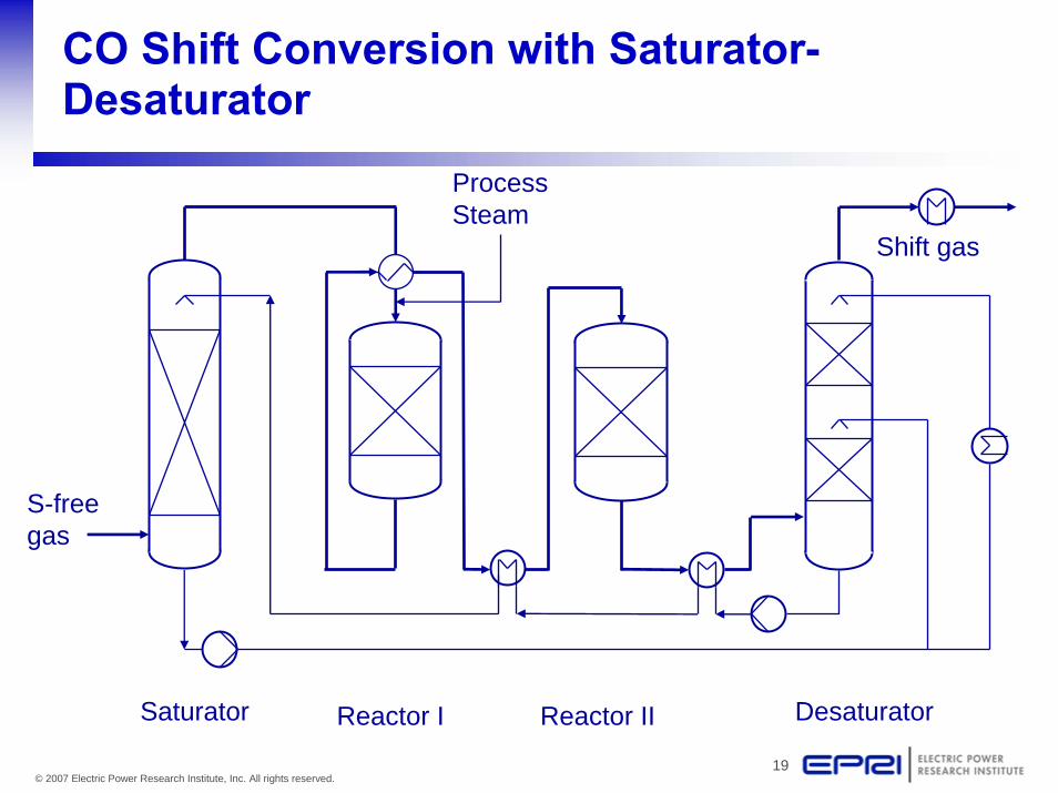
Minimizing Impact on Steam Cycle
• Impact on Steam Cycle Is Critical• Different CO and H2O Contents from Different Gasifiers
– CO range from 47% (GEE-Quench) to 64% (Shell-Gas Quench)– H2O/CO ratio range from
• >3 (GEE Quench)• through 1.3 (GEE Radiant Quench) • to 0.1 (Shell Gas Quench)
• Steam Requirement at Catalyst Will Vary with Degree of CO-Shift (Carbon Capture) Specified
• Candidate Strategies for Minimizing Net Steam Demand– Limit conversion in first bed with high CO gases– First bed partial bypass– Saturator-cooler system to optimize use of CO-Shift heat of reaction
No “one size fits all” solution

21© 2007 Electric Power Research Institute, Inc. All rights reserved.
CO2 Capture IGCC with Sour CO-Shift
O2
N2
Air
BFW
BFWSteam
Air Separation
UnitGas Turbine
HRSG
Steam Turbine
Air
H2
CO2to use or sequestration
Sulfur
AGRH2S & CO2
Gas CoolingGasificationCoal prep Sour Shift
HP Steam
Extraction Air ?
400 000 Nm³/h dry gas
560 000 Nm³/h dry gas
630 MWeGEE gas
Factor 1.4
22© 2007 Electric Power Research Institute, Inc. All rights reserved.
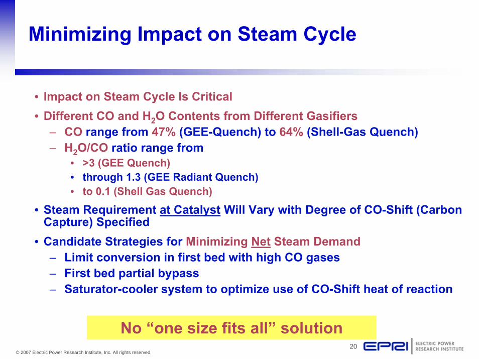
CO2 Capture IGCC with Sweet CO-Shift
O2
N2
Air
BFW
BFWSteam
Air Separation
UnitGas Turbine
HRSG
Steam Turbine
H2
Air
CO2to use or sequestration
Sulfur
AGRH2S
Gas CoolingGasificationCoal prep Sweet Shift
HP Steam
Extraction Air ?
AGRCO2
372,000 Nm³/h dry gas
362,000 Nm³/h dry gas
580,000 Nm³/h dry gas
630 MWeShell gas
Factor 1.6

23© 2007 Electric Power Research Institute, Inc. All rights reserved.
“Sour” vs. “Sweet” CO-Shift:Pros & Cons
• Both routes are mature, established technologies• Both routes have similar PFDs and similar CAPEX• For Quench Gasifier Configurations, Sour CO-Shift is favored:
– High syngas temperature– High syngas steam content– COS is hydrolyzed to H2S and CO2 (easier for AGRU to process)– Quench Gasifiers in NH3 plants with GEE Gasifiers and Sour
CO-Shift (China) and CO2 capture
• For Syngas Cooler Gasifier Configurations:– Preferred CO-Shift route is not clear and must be evaluated– Syngas Cooler Gasifiers in NH3 plants with Shell Gasifiers and Sweet
CO-Shift (China) and CO2 Capture
No Clear Choice for non-Quench Gasifiers

24© 2007 Electric Power Research Institute, Inc. All rights reserved.
UOP Selexol H2S/CO2 AGRU Capture Plant
To ClausH2S/CO2
Steam
Stage 1H2S Absorber
H2S Concentrator
N2 PurgeH2S/CO2 Acid Gas Stripper
Makeup
MP Flash
LP Flash
Stage 2CO2 Absorber
17% total CO297 Mol % CO2
35% total CO299 Mol % CO2
HP Flash
To TurbineFuel Gas95oF/495 psia
H2S/CO2 RichShifted Syngas100oF/500 psia
Lean Selexol
CO2 Rich
CO2 Rich Selexol
Semi-Lean Selexol
Reabsorber
13% total CO278 Mol% CO2
35% total CO278 Mol % CO2
300 psia
160 psia
50 psia
400 psia
Source: USA DOE/NETL–March 2007
High-to-Medium PressureCO2 Recovery Potential
H2S & CO2 Partial Pressure-Driven Process
CO2 Product Separation Required
CO2 Removal Section

25© 2007 Electric Power Research Institute, Inc. All rights reserved.
Retrofitting IGCC for CO2 CaptureAddition of CO2-AGRU Capture Section
• UOP Selexol Process Most Documented AGRU Process Choice for Separate H2S and CO2 Removal in IGCC
• CO2-AGRU Is a Complete Process Unit, with CO2 Absorber and CO2 Regeneration– Multiple flash drums w/ Selexol and other physical solvents– Thermal regeneration w/ MDEA-based chemical solvents
• Addition of CO2-AGRU– Same or different technology from H2S-AGRU?– Stand-alone or integrated with H2S-AGRU?
• Adds ~1 Bar Pressure Drop to Syngas Circuit• Adds Power Consumption (Pumping & Refrigeration) and Potential Steam
Consumption (Dependent Upon CO2-AGRU & Syngas Feed Concentrations)• Residual H2S/COS “Leakage” from H2S-AGRU Will Be Captured in CO2-AGRU,
and Present in CO2 Product• CO2 Delivery Pressures:
– Multiple elevated pressures available w/ Selexol and other physical solvents– Single lower-pressure available with MDEA-based chemical solvents

26© 2007 Electric Power Research Institute, Inc. All rights reserved.
CO2 Compression and Drying
• CO2 compression and drying to 2000+ psig for minimum miscible pressure EOR and sequestration applications
• Conventional CO2 compression– Multiple compressor stages with inter-cooling necessary to reach 2000+ psi– CO2 is first compressed through three stages of compression, intercooling,
and liquid knockout to 515 psia– CO2 is then dried to a -40°F dewpoint (100 ppmv) in a TEG dehydration
package– CO2 gas then enters a 4th stage of compression where it is compressed to
1210 psia. At this pressure, it is above CO2 critical conditions.– CO2 is then cooled in an aftercooler, but no knockout is required because it
is in the dense phase– The CO2 supercritical fluid then enters the multi-stage CO2 pump/
compressor and is discharged at the pressure needed for delivery– Steam turbine or motor drivers may be used to power the compressors
and pumps

27© 2007 Electric Power Research Institute, Inc. All rights reserved.
IGCC RETROFIT Designs for CO2 CaptureO2-Blown IGCC w/ SOUR CO-ShiftImpact Upon Gas Processing Section
• Add New (2-Stage) Sour CO-Shift + New CO2-AGRU Section– Dry syngas flow increased by 40–60%– CO2/H2S feedgas ratio increased from ~~12/1 to ~~60/1– Syngas pressure to H2S-AGRU decreased by ~2+ bar minimum– Syngas pressure to gas turbine decreased by ~3+ bar minimum
• Impact on Existing IGCC Plant– H2S-AGRU is a capacity bottleneck
• Absorber due to syngas flow• Regenerator due to higher CO2/H2S feedgas ratio
– Lower H2S concentration in acid gas due to higher feed CO2/H2S• Claus SRU undersized?• TGTU/Recycle Compressor undersized?
– Insufficient syngas pressure to gas turbine?– Acceptable H2S/COS content of captured CO2 product?– COS hydrolysis unit can be eliminated (converted to CO-Shift?)
Design Strategies Required Upfront
28© 2007 Electric Power Research Institute, Inc. All rights reserved.
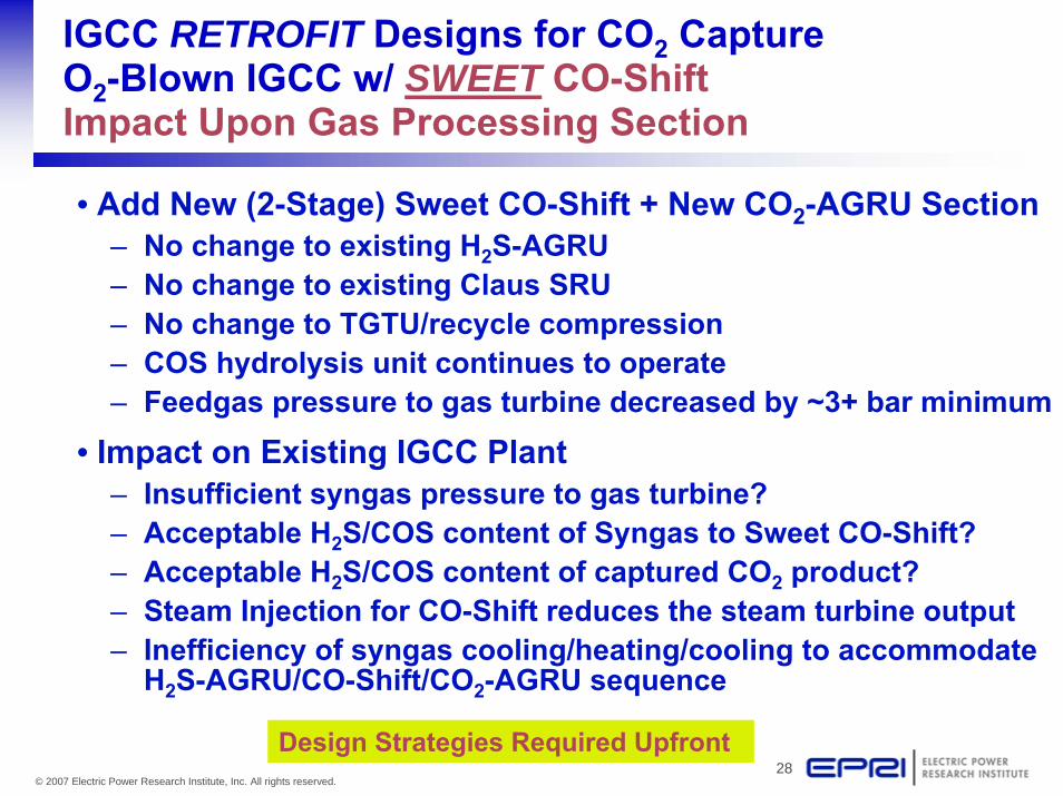
IGCC RETROFIT Designs for CO2 CaptureO2-Blown IGCC w/ SWEET CO-ShiftImpact Upon Gas Processing Section
• Add New (2-Stage) Sweet CO-Shift + New CO2-AGRU Section– No change to existing H2S-AGRU– No change to existing Claus SRU– No change to TGTU/recycle compression– COS hydrolysis unit continues to operate– Feedgas pressure to gas turbine decreased by ~3+ bar minimum
• Impact on Existing IGCC Plant– Insufficient syngas pressure to gas turbine?– Acceptable H2S/COS content of Syngas to Sweet CO-Shift?– Acceptable H2S/COS content of captured CO2 product?– Steam Injection for CO-Shift reduces the steam turbine output– Inefficiency of syngas cooling/heating/cooling to accommodate
H2S-AGRU/CO-Shift/CO2-AGRU sequence
Design Strategies Required Upfront

29© 2007 Electric Power Research Institute, Inc. All rights reserved.
CO2 Purity Specifications
• Specification on H2S / COS Concentration in CO2 Product?– Pipeline transmission regulations classifies “sour service” as a partial
pressure of H2S >0.3 kPa, which translates to 25 ppmv at 2000 psig. But this classification applies only where liquid H2O is present.
– Many pipelines in Canada transport high-H2S-bearing (dry) gases– Dakota Gasification transports CO2 w/ ~1%V H2S for 300 miles for EOR fields– How will COS be viewed in relationship to H2S?– Pipeline permitting in non-rural areas will be a critical step– Sulfur Content of CO2 can impact CO2-AGRU process selection and
CAPEX/OPEX• Acceptable Syngas (H2, CO, N2) Concentration of CO2 Product?
– Same partial pressure of CO2 leads to higher delivery pressure and greater compression requirements?
– Safety considerations?– Environmental considerations?
There is NO Standard CO2 Specification

30© 2007 Electric Power Research Institute, Inc. All rights reserved.
Source: APCI / GTC Conf – 2006

31© 2007 Electric Power Research Institute, Inc. All rights reserved.
CO2 Pipeline Specs
Office of Pipeline Safety, Dept. of Transportation
Mission Statement
To ensure the safe, reliable, and environmentally sound operation of the nation's pipeline transportation system
Permits are Required from Federal and/or State
Primary Issue is Safety
• CO2, SO2 & H2S can be dangerous
• Rupture, Leaks, etc. – CO2 pipelines typically operate at >2000 psig
Many existing permitted pipelines are currently carrying CO2

32© 2007 Electric Power Research Institute, Inc. All rights reserved.
Recent Input from Dakota Gasification Co.
Transporting CO2 w/ H2S is considered a hazardous liquid and falls under the regulatory requirements of 49CFR Part 195 for operating hazardous liquid pipelines. Even if there were no H2S in the pipeline, pure CO2 would still fall under these requirements. The pipeline is carbon steel.
Product Specifications for Sales:– Carbon Dioxide (CO2): >95%– Hydrogen Sulfide (H2S): <2%– Nitrogen (N2): <2%– Methane (CH4): <2%– Water (H2O): <15 lb/MMscf
Notes: Precautions include periodic aerial/visual patrols, periodic internal inspections (via pigging), perform periodic risk assessment studies of High Consequence Areas (HCAs) along the pipeline, a computerized leak detection system that can alert the control room of a potential leak situation by remotely monitoring the instrumentation along the pipeline, and a reverse 911 system to quickly notify the public in the area of a pipeline event.

33© 2007 Electric Power Research Institute, Inc. All rights reserved.
IGCC Issue Imposed by Pipeline Specs
EPRI CPS Energy study shows that limiting CO2 to 25 ppm sulfur can hurt economics:
8 MW Added Compression Power (due to lower recovered CO2 pressure)
19 MW Net AGR additional Auxiliary Power (refrigeration + pumps)
27 MW Total out of 553 MW Plant w/o capture
Mitigation of this penalty may be addressed through:
• IGCC capture technology optimization
• Classification of pipelines by order of difficulty

34© 2007 Electric Power Research Institute, Inc. All rights reserved.
IGCC RETROFIT Designs for CO2 Capture:Additional IGCC Plant Impacts
• Loss of MWth and Mass in Gas Turbine Fuel– Exothermic CO-Shift reaction means less fuel energy available
to fire the GT– High Btu/lb (kJ/kg) content of H2 versus CO means less mass
flow in fuel stream (by ~50%)– Combined impact results in 5–10% less power output from GT
depending on magnitude of shift
• Loss of Plant Net Power Output due to ASU and Gasifier Sections not Sized for Full Fuel Loading to GT
• Reduction in Available Extraction Air– Air extraction for ASU is usually decreased in order to “fill” the
expander section of the turbine– Additional Air Compressor for ASU

35© 2007 Electric Power Research Institute, Inc. All rights reserved.
IGCC RETROFIT Designs for CO2 CaptureAdditional IGCC Plant Impacts (cont’d)
• High H2 Content of GT Fuel– Commercial Experience of GT?– Increased H2O content of exhaust causes higher heat
transfer rates to hot section– Increased flame speed of H2 affects design of
combustion section– May require firing temperature de-rate– May not be an issue at intermediate CO2 capture levels

36© 2007 Electric Power Research Institute, Inc. All rights reserved.
IGCC RETROFIT Designs for CO2 CaptureAdditional IGCC Plant Impacts (cont’d)
• Loss of Steam to Steam Cycle– CO-Shift (particularly with Sweet CO-Shift)– CO2-AGRU Solvent Regeneration (AGRU-dependent)
• Additional Internal Power Consumption– CO2-AGRU (Pumping & Refrigeration)– CO2 Compression– ASU Compression

37© 2007 Electric Power Research Institute, Inc. All rights reserved.
Retrofit Execution Schedule
• Perform like typical refinery turn-around
• Total project duration (excluding permitting):~2 years
• Turn-around can be done in about 6 weeks with adequate pre-planning
• Allow reasonable amount of time for plant re-start and operating stability
Source: PCK Schwedt in Erdöl Erdgas Kohle, 2/2004

38© 2007 Electric Power Research Institute, Inc. All rights reserved.
Retrofitting IGCC for CO2 Capture:Conclusions
• Current definition of “Capture Ready” is vague
• IGCC projects will require a Design Strategy for the correct balance between Pre-investment and Post-investment for CO2 Capture
• Each IGCC Base Plant Design will require a different Retrofit Strategy

39© 2007 Electric Power Research Institute, Inc. All rights reserved.
EPRI’s CoalFleet forTomorrow Program
• Build an industry-led program toaccelerate the deployment ofadvanced coal-based power plants;members now span five continents
• Employ “learning by doing” approach; generalize actual deployment projects (50 & 60 Hz) to create design guides
• Augment ongoing RD&D to speed marketintroduction of improved designs and materials
• Deliver benefits of standardization to IGCC (integration gasification combined cycle), USC PC (ultra-supercritical pulverized-coal), advanced CFBC (circulating fluidized-bed combustion) and oxy-combustion– Lower costs, especially with CO2 capture– High reliability and efficiency– Near-zero SOX, NOX, and PM emissions– Shorter project schedule– Easier financing and insuring

40© 2007 Electric Power Research Institute, Inc. All rights reserved.
Questions & Discussion