Theoretical Determination of Rate Constants from Excited ...

AFAPLTR-68-143
CO
CO
S
THEORETICAL DETERMINATION OF CONVECTION HEAT-TRANSFER COEFFICIENTS
AROUND A TURBINE AIRFOIL (WITH COMPUTER PROGRAM)
LUCIEN L. DEBRUGE
WALKER H. MITCHELL
f
TECHNICAL REPORT AFAPL-TR-68-143
APRIL 1909
\
D D C^
A MAY 85 OTI j
IlkisEinj'dui c
Thi« document has been approved for public release and sale; its discrlbuClon is unlimited.
AIR FORCE AERO PROPULSION I^ABORATORY AIR FORCE SYSTEMS COMMAND
WRIGHT-PATTERSON AIR FORCE BASE, OHIO
.t£ILONAL TECHNICAL INFORMATION SERVICE
v» nui (^

UNCLASSIFIED •jcuftJyClMjiftcjHo^
DOCUMENT CONTROL DATA R&D (S»turllr clmitlllt»!!»* ml IHI; kotty »I m*»lrmrl mnd Indttlnf mnnetmllon muH b» mlmnä ml hf> Ihm oumtmll tmmorl It tlmmmlllmdi
I ORIGIN» TINO AC TiviTY fCerporao aulftar;
Air Force Aero Propulaion Laboratory Wright-Patterson Air Force Baae, Ohio 45433
a«, nifom ■■cuniTT CL*t*iric*TioM
VHCLASSIFIED lb aKOU»
1 MCPOKT TITLK
THEORETICAL DETERMINATION OF CONVECTION HEAT-TRANSFER COEFFICIENTS AROUND A TURBINE AIRFOIL (WITH COMPUTER PROGRAM)
I (Typ* ml tmpmt mnd Inclumlrm dmlmm)
t *u TMORKI (Pint nmmtm, mtlddlm htlllml. Imml nmmtm)
Lucien L. Debmge Walker H. Mitchell
• nmpomr DATI
M. CONTItACT OM
Ta. TOTAL NO. OF P«ect
66 Tk. NO OF WIH
». wxojtc T NO. 3066
«. Task 306606
AFAPL-TR-68-143
OTHKH NCPOMT NOI*l (Any 0)1» npmtl)
olhmt fMjMD#rc dtmt mtmy mm mmml^^md
This document has been approved for public release and sale; its distribution is unlimited.
II «u/'lAMBNTAStV NOTCt II •»ONCOKIN« MILITAKT ACTIVITY
Air Force Aero Profplaion Laboratory Wright-Patterson Air Force Baae, Ohio 45433
i AatTMACT
A High-Temperature That Facility is being installed in the Air Force Aero Propulaion Laboratory for analyzing varloua sophisticated cooling designs over an extended gaa temperature range. The objective is to evaluate these schemes with respect to gaa temperature and pressure levels. The experimental data will be correlated with theoretical predictions to provide a basis for future high-temperature turbine blade designs.
TWe report describes a theoretical prediction of the convection heat-transfer coefficient distribution on a tost blade and the computer program for making the necessary calculations. The program is written in Fortran IV ready for an IBM 7094. The input and output are described. The program starte with the blade surface pressure distribution obtained experimentally and yields the heat-tranafer coefficients on the blade contour.
DD FORM 1473 UNCLASSIFIED Security CUnificatioi

UNCLA8SIFIEP BSNB CESHBSSB
Boundary Layer Convection Heat Transfer
UNCLASSIFIED ••curity Claasiricatlon
AFAPL-TR-68-H3
ABSTRACT
A High-Temperature Test Facility la being installed in the Air Force Aero Propulsion Laboratory for analyzing varioua sophisticated cooling designs over an extended gas
temperature range. The objective la to evaluate these schemes with respect to gas temperature
and pressure levels. The experimental data will be correlated with theoretical predictions to
provide a basis for future high-temperature turbine blade designs.
This report describes a theoretical prediction of the convection heat-transfer coefficient
distribution on a test blade and the computer program for making the necessary calculations.
The program is written in Fortran IV ready for an IBM 7094. The input and output are
described. The program starts with the blade surface pressure distribution obtained
experimentally and yields the heat-transfer coefficients on the blade contour.
Ill

AFAPL-TR-e8-143
1 THEORETICAL DETERMINATION OF I CONVECTION HEAT-TRANSFER COEFFICIENTS
AROUND A TURBINE AIRFOIL I (WITH COMPUTER PROGRAM)
LVCIEN L. DEBRUCE
WALKER H. MITCHELL
This document has been approved for public release and sale; its dlsCrlbudon Is unlimiced.

AFAPL-TR-68-143
FOREWORD
The work on which this report is based was accomplished under Project 3066. "Gas
Turbine Technology," Task 306606. "Turbine Research Exploratory Development," using
the computer facilities of the Turbine Engine Division, Air Force Aero Propulsion Laboratory,
Wright-Patterson Air Force Base. Ohio. This work was administered under the direction of
Mr. Charles E. Bentz. Project Engineer.
This report describes vork conducted between 1 July 1968 and 1 October 1968.
Mr. Walker Mitchell was responsible for the development of the computer program and
Mr. Luden Debruge for the theoretical development and discussion. Tills report was submitted
by the authors October 1968.
This technical report has been reviewed and is approved.
fu^s £ sL. ERNEST C. SIMPSON Director, Turbine Engine Division Air Force Aero Propulsion Laboratory
ii

AFAPL-TR-68-143
TABLE OF CONTENTS
SECTION
I INTRODUCTION
II THEORY AND DISCUSSION
HI RESULTS AND CONCLUSIONS
APPENDIX - COMPUTER PROGRAM
REFERENCES
PAGE
1
2
18
2]
52
AFAPL-TR-68-143
ILLUSTRATIONS
FIGURE
1. Channel Configuration (From Reference 1)
2. Suction Surface Velocity
3. Pressure Surface Velocity
4. Suction Surface Velocity and Pressure
5. Pressure Surface Velocity and Pressure
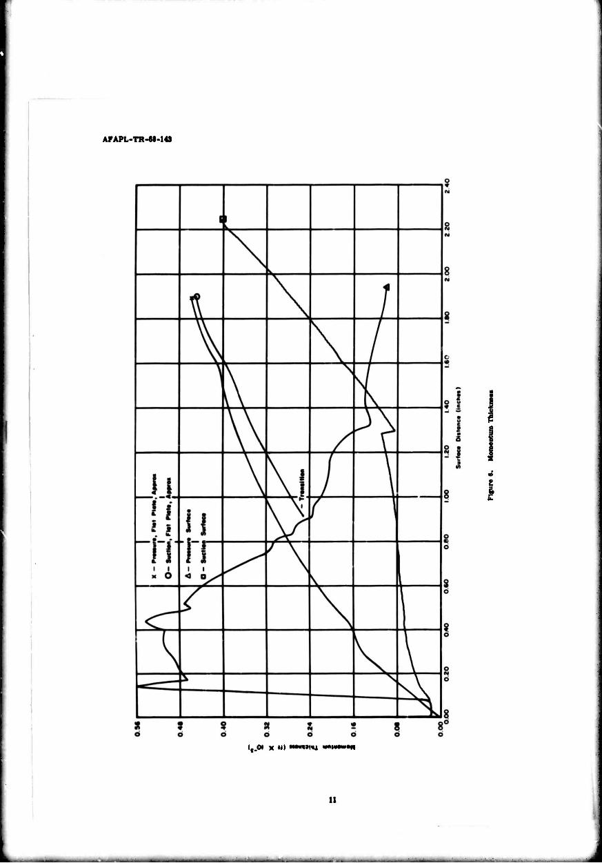
6. Momentum Thickness
7. Suction Surface Reynolds Number
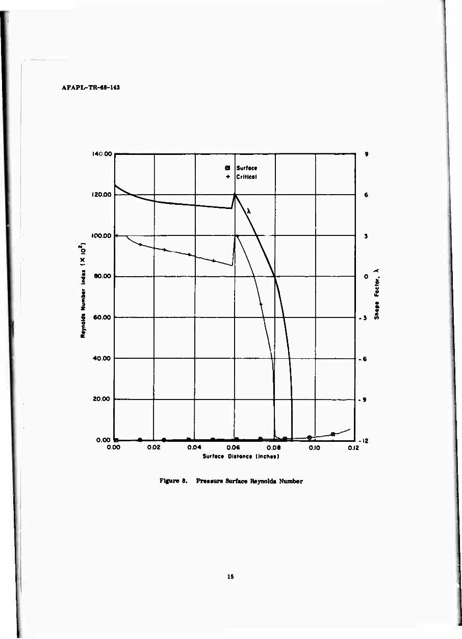
8. Pressure Surface Reynolds Number
9. Suction Surface Heat-Transfer Coefficient
10. Pressure Surface Heat-Transfer Coefficient
PAGE
3
I

AFAPL-TR-68-143
SYMBOLS
A
A*
Cf
CP I
H
n
P
Pr
r
R
T
Vor Ü
vr
x
y
p
Y
8
8*
8W
X
B
T
my
channel cross-sectional area
channel cross-sectional area at which Mach number is unity
turbulent coefficient of skin friction
specific heat at constant pressure
convection heat-transfer coefficient
velocity shape factor (turbulent boundary layer)
distance along velocity potential line
local Nusselt number
pressure
Prandtl number
radius
gas constant
temperature
velocity
mid channel reference velocity at a distance my from centerline of cascade
surface distance from stagnation point
distance along radial potential line
density
ratio of specific heats
kinematic viscosity
viscosity
boundary layer thickness
displacement thickness
boundary layer energy thickness
velocity shape factor (laminar boundary layer)
momentum thickness
shearing stress
vll

~. '
AFAPL-TR-68-143
SUBSCRIPTS
m refers to mid-channel conditions
CR refers to critical condition
0 stage entrance conditions (cold flow)
1 stage entrance conditions (hot flow)
n distance along velocity potential line
no distance along potential line (cjld flow)
nl distance along potential line (hot flow)
8 static conditions
ad adiabatic conditions
vill
i

AFAPL-TR-«8-143
SECTION I
INTRODUCTION
Currently, the Air Force Aero Propulelon Laboratory le irutalling an in-houae High-
Temperature Teat Facility which will be used Initially to analyze various cooling techniques, aa applied to turbine engine blades, over an extended gaa temperature range. The objective la to evaluate these cooling schemes with respect to gas temperature and pressure levels. Experimental data will be correlated with the various theoretical predictions of blade cooling effectiveness, thus providing a basis for future high-temperature turbine blade designs
Hie experimental data used la that obtained from the recording of surface metal temperatures by Infrared thermometry. In the theoretical prediction of turbine blade temperatures, cooled or uncooled. the major stepe are the calculation of the convection heat-transfer coefficients on the blade surface and the calculation of the driving or adlabatlc wall temperatures. These calculations depend primarily on the accuracy with which the
behavior of the boundary layer la predicted. It la generally assumed that the Introduction of a cooling fluid In the boundary layer has a negligible effect on the convection heat-transfer coefficients, but It affects considerably the adlabatlc or driving wall temperature.
This report presents a theoretical approach to the problem of determining the adlabatlc wall temperatures and the convection heat-transfer coefficients .
This program la written In Fortran IV ready for use on an IBM 7094 for an uncooled blade and the computer program to which It led. The results obtained from the program developed here are compared with those from the computer program developed by the AUlaoo Division of General Motors on Contract AF 33(615)-2985.

AFAPL-TR-68-143
SECTION n
THEORY AND DISCUSSION
The velocity of a perfect, frlctlonless, compressible gns flowing through a channel, at
any point across a potential line, la given by the equation
v« vw, ..p[--A-(c2-C»)] (I)
where, for a nourotatlng channel.
^my ■ V eip [ yy - 4- «in2 f dy] V«. ^ V^ e«p I y - jr tw 4' d» I (2) 'yo
la the mid channel velocity at a distance y from a reference point y0 along a radial potential
line and Vy0 Is the velocity at the reference point (Figure 1). It la seen from Equations 1 and
2 that V Is strictly a function of channel geometry %nd VyQ.
In the computer program currently In use at AFAPL (Reference 1), Vyo la arbitrarily
chosen; then, the fluid velocity and density are evaluated at specified locations along a
velocity potential line, the latter being obtained from the equation
^H^)(^n(?tT)
Integration of the product Vn pn over a given channel cross section yields the total mass
flow which la compared with the required flow (usually the maximum or choked flow). Vy0 Is
Improved until A ^ Vn dA (required flow) < tolerance. Use of this computer program
require! an accurate description of the channel configuration at each of the cross sections
where the channel wall velocity must be obtained. Eleven croes sections are presently used
to provide enough data for interpolation of the velocity profile along the channel walls
between the stage entrance and the throat, beyond which extrapolation Is depended upon to
obtain the velocity profile. As inputs to the program, curvatures, length of velocity potential
lines, and the angle between the gas stream direction upstream of stage entrance and the mid channel stream-line must be measured or calculated. A table of V/Vcr versus axial chord

AFAPL-TR-68-143
PrMturt Sue foe« Tip Circumftrtntiol Poftntiol Lint
Tip Mid Chonntl Lint
Suction Surfoct
Portlltl to Axis of Rototion
Figure 1. Channel Configuration (From Reference 1)
AFAPL-TR-68-143
distance must be prepared from a curve drawn through the extrapolated and interpolated
points as an input to a second program (described later) which in turn translates V/V versus CR
axial chord distance into VALR versus surface distance from the blade stagnation point and
ultimately yields the convection heat-transfer coefficients along the blade profile.
It follows that, even when only changes in the gas flow parameters (P0, T0, RQ, /, V )
are involved, preparation of a new table from the output of the first computer program
requires several hours. When a different blade profile must be tested, a tedious, time-
consuming determination of the channel parameters listed above must also be conducted.
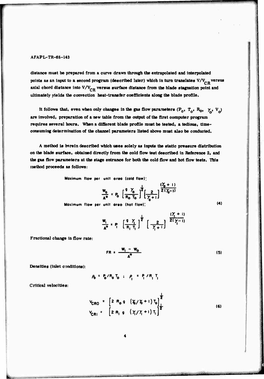
A method is herein described which uses solely as Inputs the static pressure distribution
on the blade surface, obtained directly from the cold flow test described in Reference 2, and
the gas flow parameters at the stage entrance for both the cold flow and hot flow tests. This
method proceeds as follows:
Moiimum fio« per unit ores (cold flow);
i !*♦ •> 9 yo TV 2 i2<y0-i)
A» •• IRO T0 J IX-HJ
Moiimum flow per unit ores (hot flow): (4)
Fractional change in flow rate:
(X"»- I)
A» 7 IR.T, J I x^iJ
FR « W, - W0
(S)
Densities (inlet conditions):
Critical velocities:
\m ' [2Ro' «/«*')To it
VCRI ' [2R« « (W*)7*
i (6)
-—

AFAPL-TR-68-143
Local channel cold flow densities:
«•«H-^fc)']"^ Desired local channel, hot-gas mass flow:
p V ♦ lf> V WFR\ = 60 'no no ^ no *o )\ )
Local channel hot flow density:
X-'x / Vno* & VM\*, 1 *. ■'A'-iWi'*^)] a.X-i
CR,
AV ^ is changed until no ■
60 - /ft, (V„o ♦ A Vno) < toltronct
(8)
(9)
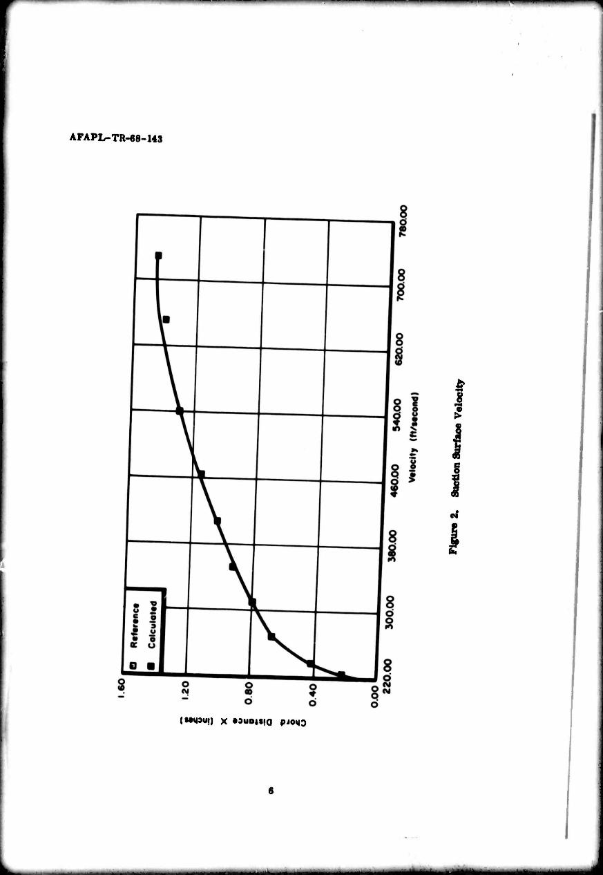
Figures 2 and 3 show the velocity versus axial chord distance plots obtained from the former computer program and the present method for identical input gas stream conditions.
Hie computer program presently in use at AFAPL calculates convection heat-transfer coefficients and adlabatic wall temperatures along the blade profile. Static temperature and pressure are calculated outside the boundary layer from channel flow theory, using the following equations:
w.H^HH&n i-ii+r
Cp , /A , PR, and p , characteristic of the fluid, are entered as tables for the
appropriate range of temperatures and pressures.
AFAPL-TR-68-143
I
§
(Mgaui) x »auoitio pjoMQ
^^».^^■••i

f ^
g 3 00 00 I I
f«»M3ü.) x Mu0|t,0 pj0MD

AFAPL-TR-68-143
Hie calculation of convection heat-transfer coefficients and adiabatlc wall temperatures Is then carried out on the following assumptions:
1. On the suction side, the boundary layer Is laminar from the stagnation point to
the point of minimum pressure. From this latter point on, the flow Is turbulent.
2. On the pressure side, the boundary layer Is turbulent from the neighborhood of
the stagnation point to the trailing edge.
The adiabatlc wall temperatures are obtained from the following equations:
i (lominor) Tod s TS "*■ (To " V PR
(turbulent) Tod « Ts ♦ (T0 - Ts) PjJ»
On the leading edge and In the laminar part of the boundary layer, Squire's method
(Reference 3) for the calculation of heat transfer on a cylinder and on a flat plate Is used. In the turbulent part of the boundary layer, an approximation of the von Karman formula for heat transfer In turbulent flows Is used.
N. • ic; ^ \ assuming the local coefficient of skin friction for a flat plate to be
i el = -^V 8 0.0128 (■*$-) (10)
where • öu) « 0.036 i (-ijf-) (II)
The fact that the Reynolds numbers anticipated In the testing of the blades will be low, a io5. and that, for the pressure profiles obtained (Figure 4), -4^- Is small In an
extended neighborhood of the minimum pressure point makes questionable the assumption that the latter coincides with the transition point. Also, Equation 11 suggests that 0(x) Is rather insensitive to fluctuations in U, the latter being overshadowed by those In x. A comparison of Figures 4 through 6 shows that the drastic changes in the velocity profiles, particularly on the pressure side, are not reflected in Bin) and that, for instance, the momentum thickness of the turbulent boundary layer is approximately the same on both pressure and suction surfaces beyond a surface distance of 1.3 inch, corresponding approximately to the transition point on the suction side. Obviously, this behavior of 6 will

AFAPL-TR-M-143
IlSdl •'"»»•'<< 3'lOlS •I*i<*t
1 I
I
I,« X II) <UMW* Hmi«i>3

AFAl'l -TR-88-1«
nsd: »'"»WM j,,o,s »JOIJOS
1,01 x »••»•t/in «,i3o,.A IMW.,,3
I 5
I
10
AFAPL-TR-68-143
itjot x ui ***wni wKtwon
11

AFAPL-TR-68-U3
be reflected in N . since
Nx voritt with 9 , ond, thertfort , h (x)
In an attempt to evaluate the discrepancies that might result from the preceding
observations, we have adopted the theories of H. Schlichtlng and E. Truckenbrodt(References 4
and 5, respectively) relative to the determination of the transition point and to the computation
of a two-dimensional turbulent boundary layer momentum thlcknesst to the specific
requirements of AFAPL turbine blade hot testing investigation and incorporated them in a
computer program described in this report. These theories will be described briefly.
In the new program, the laminar boundary layer is calculated using Squire's method
which uses a simple quadrature to obtain 6 , where
02 , _2^Si_ fo dl (|2) u IT *■ « o
The displacement thickness S* and boundary layer thickness 8 are obtained from the
assumptions
i-^^-iV The shape factor of the boundary layer velocity profiles is defined as
A ' w d*
The pressure decreases for X >0 and increases for X< 0 , hence the point of minimum
pressure occurs for X = 0
Originol form:
4*. J.. _L x -i s PL- -1- X l— k*) 8 10 120 ' 8 \ 315 945 9072 /
A family of neutral stability curves defined by the shape factor X and representing
the variation of 8 * with the Reynolds number u$* has been obtained by H. Schlichtlng u
and A. Ulrich (Reference 4). The point on these curves at which the Reynolds number R**
has its smallest value is defined as the limit of stability for the laminar flow of interest.
This R* * is called the critical Reynolds number, Rfi*rR*
12

AFAPL-TR-68-143
It follow« that Rft*£D can b* plotted as a function of X , hence, of the surface distance
x. Hie intercept of this curve with that representing the variation of the local Reynolds
number •*{£- with a will ytald the separation point.
As may be seen from Figures 7 and 8 for small x's, R * * is small and X is large. As x becomes larger, this relationship Is Inverted and consequently Rs* decreases while R* *
increases.
Hie tormented profile of the variation of Rfi* with x is to be attributed to the dependence du 0
of X or,^nr which undergoes abrupt changes along the blade surface.
Hie calculation of 6 from E. Trucksnbrodt's method (Reference 5) is based on the energy Integral equation
u» d. v ; Tjjfn (13)
where the energy thickness 8** la a measure of the kinetic energy loss resulting from
friction and is defined as
US8**« / U(yl[u* d) - U*(y)Jdy
and
1.12 X 10"* m represents a good approximation of the friction work peiiormed In the boundary layer by the
shearing stresses r (H. Schllchting).
Integration of Equation 13 was performed by E. Truckenbrodt (Reference 5) and yields
$ (Jf )*.(:,. A/" uLi; m
13

AFAPL-TR-M-I«
y •»•t>»i MO«S
i
I
1,01x1
14
AFAPL-TR-eS-Ua
14c 00
120.00
100 00
2 X
I 8000
I 60 00 -
40.00
20 00
0.00 I»
■ Surfoct
Criticol
\x
-^-^ -J \N \
\
\
1
-^t; _^
000 002 0.04 006 0.08 Surfoct Oittonct (inchts)
I o a
-3 ««
• 6
-9
-12 0.10 0.12
Figure 8. Pressure Surface Reynolds Number
15

AFAPL-TR-68-143
which may be rewritten using the turbulent coefficient of skin friction for a flat plate aa
0U) I
where
(*r .^ r-j-,...'*-f a)
«.••i*M(^(A-r*(t)) (n-M)
(14)
represents the laminar portion of the boundary layer.
It may be seen from Equation 14 that 6 is highly sensitive to the variations in the
velocity U. Figures 4 through 6 afford a comparison of the variations of 9 and u with
respect to i for the suction and pressure sides.
A very good value of the local coefficient of skin friction could have been obtained through
the relationship
m but unfortunately E. Truckenbrodt's method for the variation of the shape factor H in the
range of transition could not he used because -~— in this range was too small. Instead. "zCJ was obtained from
ß»' • .0128 •/m 29
'And this value Introduced Into the von Karman formula
N, « -f C' R« %
•♦»>/Fr((»-')* ^{"i {'■-'))} which takes into account the variation of the Prandtl number.
16

AFAPL-TR-68-143
The convection heat-transfer coefficient for the laminar part of the boundary layer is
calculated from Squire's method, using the universal function
obtained from intergratlon of the energy equation with P < 1. Squire's paper (Reference 3)
Is referred to for the details of the procedure. The new computer program, instead of
using a table of H versus A , computes H (A) at every point where h is calculated.
17

AFAPL-TR-68-143
SECTION m
RESULTS AND CONCLUSIONS
On the suction side, the transition point as determined in the new program is shifted by
0.37 inch downstream. At this point hi« 35% higher than the h obtained from the former
program at the same location (Figure 9). On the pressure side, Figure 10 shows that the new
convection heat-transfer coefficient assumes lower values Immediately downstream of the
transition point with a maximum change of 40% with respect to the former h at the same
location and increases at a faster rate to assume a value at the trailing edge representing
an increase of 36% over the former h.
The average value of h over the blade remains essentially unchanged when Truckenbrodt's
method is used, so tnat the total amount of coolant required for the blade will not be changed
significantly.
The large discrepancies in local heat-transfer coefficients would necessitate a
redistribution of the coolant flow formerly determined from the Allison program.
Confirmation of the validity of the improvements suggested in this report will necessitate
experimental data which will become available when the AFAPL in-house testing program is
initiated.
18

AFAPL-TR-68-M3
I ■ £
I I |
I
I
■•t it '<•
■nir iu»oi,)»03 j»(«uoii IO»H
1»

AFAPI.-TR-68-143
■ u
\ \
04
\\
V \
^
^y 1 i
8
8 8 8 8 8
8 o 5
8 I
8 - - i
|
8 I
\ V)
I
I
Ql ,U»I3.((»03 i*t«W*ii IO*H

ArAPL-TR-68-U3
APPENDIX
COMPUTER PROGRAM
21

AFAPL-TR-68-143
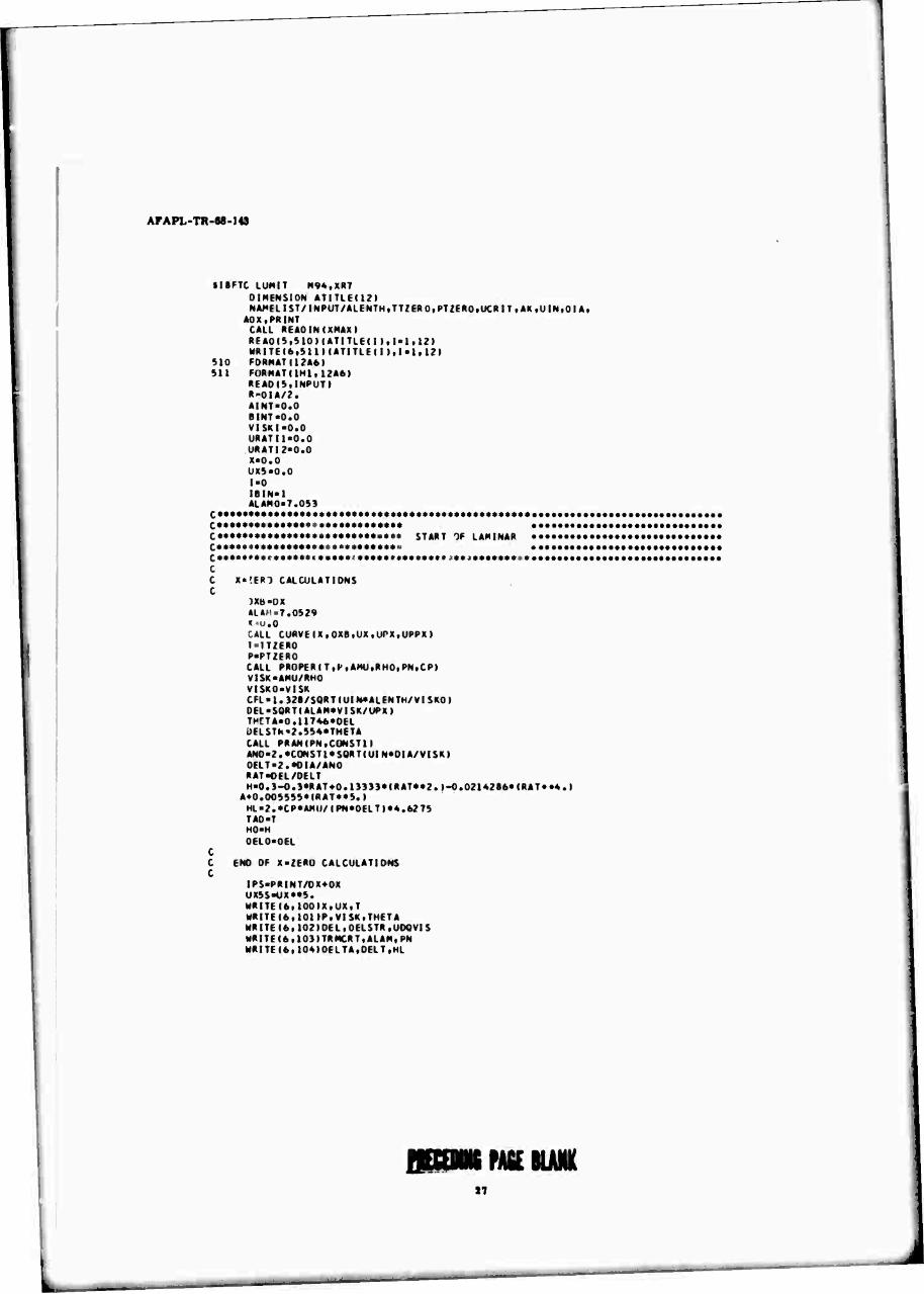
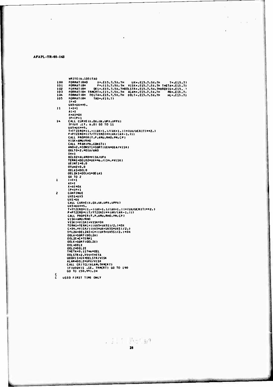
PROGRAM FUNCTIONS
LUMIT
This is the main program. It is divided into two basic parts: laminar boundary layer and
turbulent boundary layer. Initially the program reads in the Input data, calculates the initial
conditions of the laminar boundary layer, iterates through the laminar calculations until
transition is reached, then proceeds into the turbulent section and iterates until the end of the
blade is reached. All integrations are performed in the program and are basically trapezoidal.
VLOCT (alternate entry CURVE)
This routine reads in the velocity profile versus surface distance. It uses the alternate
entry to find the velocity and the first and second derivatives for a given surface distance.
It should be noted that the first and second derivatives are somewhat Inaccurate since they
are based upon a finite length rather than a point.
Uses subroutine TLOCK
DTFRMX
This routine solves the universal function of DELTA for DELTA greater than 1. It
iteratlvely solves for the unknown DELTA given H (DELTA).
Uses subroutine AFQUIR.
See Chapter XII of Reference 3.
PRANX
Ulis routine looks up in a table the constant used in the heat-transfer equation near the
stagnation point as a function of the Prandtl number.
Uses subroutine SRCHX
PROPEX
Tills routine calculates the viscosity, density, Prandtl number, and specific heat of
air as a function of temperature and pressure.
Uses subroutine PROCOM and TLOOK.
22

AFAPL-TR-68-143
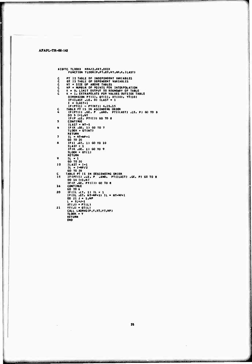
TLOOKX
The function subprogram TLOOK Is a general purpose routine to perform a table look-up
In a two-dimensional table (dependent variable versus Independent variable). It first locates
the input independent variable in its table, then takes the nearest 'N* pairs of points and calls
subroutine LAGRNG. This program uses an interpolating polynominal of degree 'N-l', in
the Lagranglan form, to evaluate the dependent variable. TLOOK also has the capability of
remembering where it found the independent variable in the table. Thus, search time is
saved when the next time it is called the independent variable has changed only slightly.
Use subroutine LAGRNG.
LAGRNG
See description of TLOOKX.
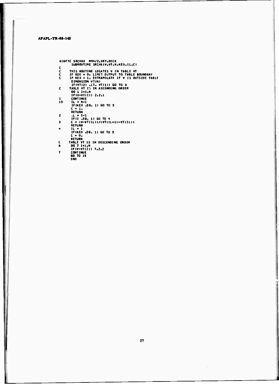
SRCHXX
Ihls subprogram is a table lookup routine using linear interpolation.
PROCOM
This routine calculates the thermodynamic properties of air or alr-JP4 mixtures. Given
temperature and fuel-air ratio, it calculates speed of sound, ratio of specific heats, specific
heat of constant pressure, gas constant, and nonpressure biased entropy and enthalpy.
AFQUIR
This program is a quadratic convergence routine. It is a routine having general
application and is used to converge practically any function.
CRITXX
This routine takes an input shape factor (ALAM) and looks up on a curve the critical
Reynolds number.
Uses subroutine SRCHX.
See Chapter XVII of Reference 3.
INPUT VARIABLES
NUMB - number of points in velocity profile curve
XS - surface distance
VS - surface velocity
ALENTH - characteristic bilde length
23

AFAPL-TR-68-143
TTZERO - total emperature of free stream
PTZERO - total pressure of free stream
UCRIT - sonic velocity of free stream
AF - average specific heat ratio
UIA - free stream velocity
DIA - leading edge diameter
DX - Integration Interval
PRINT - print Interval
OUTPUT VARIABLES
Laminar
X - surface distance
UX - surface velocity
T - static temperature of surface
P - static pressure of surface
VISM - kinematic viscosity
DEL - laminar boundary layer thickness
THETA - momentum loss thickness
DELSTR - boundary layer displacement thickness
UNDVFS - characteristic surface Reynolds number
TRMCRT - critical surface Reynolds number
A LAM - velocity profile shape factor
H - universal function
DE LT - thermal boundary layer thickness
HL - convection heat-transfer coefficient
TND - adiabatlc wall temperature
Turbulent
X - surface distance
UX - surface velocity
T - static temperature of surface
P - static pressure of surface
VISN - kinematic viscosity
TAP - adiabatlc wall temperature
CF2 - surface friction coefficient
24
■■■•-

AFAPL-TR-68-14S
THE TA - momentum loss thickneas
PN - Prandtl number
RHO - density
TUQV - Reynolds number associated with momentum loss thickness
HX - turbulent heat-transfer coefficient
INPUT FORMAT
First Cards
Curve title card (12A6)
Used to Identify the particular velocity profile
Second Cards
NUMB (13)
Number of points In velocity versus surface distance curve
Next NUMB cards
XS VS (2F10.0)
Surface distance and velocity cards
Next Card
Case title card (12A6)
Used to Identify the particular case
Next Card(s)
NAME LIST/INPUT/
Case Input; see Input variables for definition.
25
J
r 1
AFA PL-TR-68-143
»IBHC LUMIT M9*.X«7 DIMENSION «TITLEU2t NAMmST/INPUT/AlfNTH.TI/K-n.PT/MO.UCRIT.AK.UIN.Ol«,
AOX.POINT CALL MAOINIXMAX) REAO(5.S10MATITLE(I I.I-l.U) HRITE(6.SiniATITLEIII.I«ltl2l
510 FORMAT(12A6I 911 KlHHATIlMl, 1?*6)
REAOISflNPUT) «"OIA/J. AINT-0.0 BINT «CO VI SKI-0.0 URATI1-0.0 URATI2-0.0 X-0.0 UX»«0.0 1-0 IBIN-1 ALAM0>7.053
••••••••••••••••«•••••••••••* START If LAMINAR ••••••••••••••••••••••••••••••
»•■tf ) CALCULATIONS
)XB-OX ALAH>7.0S29 l.u.O CALL CURVEIXfOXe.UXfUPXtUPPXI T«TT/ERO P-PT2ER0 CALL PROPERITtPi*HU.RHOfPNfCP) VISK-AMCI/RHO VISKO>VISK CFL-1.32a/SORT(UlM*ALENTH/VISKOI OEL*SORTIALAM«VISK/UPXi THCTA«0.11T4«*0EL üELSThi2.554*THETA CALL PRANIPNtCONSTll AN0-2.*C0NST1*S0«TIUIN«0IA/VISKI DELT«2.«0IA/*N0 RAT-OEL/OELT H>0.3-0.3*RAT«0.13333*1RAT**2.1-0.021«286*(RAT**4.t
A*0.OOS5»S*IRAT**S.I HL-2.*CP*AMI)/IPN«0ELTI*4.6275 TAO-T HO-H OELO-OEL
ENO OE X-2ER0 CALCULATIONS
IPS>PRINT/OX*OX UXSS>UX«*9. WRITE(6>100IXtUX,T WRITEI6.10nP.VISKiTHETA HRITEI«.102I0EL.DELSTR.U00VIS MRITEI6I103)TIIMCRTIALAM(PN NRITEI6.104IDELTAt0ELT,HL
OBOIIB PAtE BUNK J7
APAPL-TR-e8-143
MlTIIAtlMITM 100 FOMMATiSHO M • , H ■., 7, ■) » , 7H u x . . 11 *>. 7 , SX , 7h 1',tli.1l 101 MmM»T(»H f-.U1«. 7,Sx, 7H VlSK>«m.7t>X.TH IHH*.,t 1S.7) 102 FORNATISH ML>tElt.7lSX.7H0EL$TR-lEl».7t9X.7HU00VI$«tEl$. > 10) FUKMATIIH TRNCRT» t El !>. 7, »X. 7H HAM« ,C1S.7.5X,7H PN«lEl».7i 10« FORMATISH OELTA'.EIS.7,9X.7H CELT-.EIS.7t9Xf7H HL«tE19.7l 10» FORMATiaH TAD«tEl».7l
IR>0 UX5«UX»»5.
11 ['1*1 Al-I X>AI*OX IP-ir»l
14 CALL CURVEIX.OX.UXiUfXtUPPXI IMUX .LT. 6.01 CO TO 11 UX$*UX**9. T«TT|ER0«I1.-IIAK-1.I/(AK*1.I l*IUX/UCRITl**2.I P«PT2ER0*I(T/TT;ER0I**(AK/IAR-1.III CALL PROPERIT(P|ANUfRHO.PN>CPI VISK«AMU/RHO CALL PRAN(PNtC(lNSTll AWW.'CONSTI'SORTIUIMOIA/VISKI 0ELT0-2.*01A/AND IN*1 0£L02-ALAN0*VISK/UPX TERN1>OEL02*UX*««./I )4.*Vi SK I UEINT1«0.0 0TUN2«0.0 DELAS-OELO 0EL2AS>0ELAS*0ELA$ CO TO 2
AI>1 X>AI*OX IP-IP*»
2 COMTiNUE WMIWl uxs-ux CALL CUItVE(X(OX,UX,UPX,UPPXI UI9«UI**S. T-TT2ER0*I1.-(IAK-1.I/IAK*1.II«IUX/UCR1TI»*2.I P-PTZERO«riT/TT2EROI**IAK/IAK-l.Mt CALL PROPERIT.PtAMU.RHO.PNtCPi VISK-AMU/RHO VISKI*VlSKI*VISK*OX TERNWERN1«IIUX»*UX)S)/2.)*0X C«)4.*VlSK/ll(fXS*UX*UX»S*UXSI/2.l ?FL2A«OEL2AS»C*IIUX»«UX»S»/2.l*OX OELA-SORTI0EL2AI 0EL2E<*TERM1 OELE-SO*T(0EL2EI 0EL>0ELE DEL2-OEL2E THETA-0.1I74«*0EL DEL$TR-2.»94*THETA UO0VIS«UX«OELSTR/VI$K ALAM>0EL2«UPX/VI$K CALL CRITCLIALAM.TRMCRTI IflUDOVIS .CE. TRMCRTI CO TO 190
CO TU I»0,9«ItIN C C USED FIRST TIME OMIT
28
L

I
AFAPL-TR-M-l«
C
c c 99
10S
soo
IH*2 ■IM CALL CUftVE(XltOX(UXltUfXlfUPPXn Z1-PN*I0EL0*UX1*M0I**2./I4.*VISKI Z2«Il«IHO*IUXl<»UXi/2. I*0X Z21-OEL0*«2.*UXl**6./m.*VISKI ZZ2-ZZ1«IIUX1«*S.'»UX**S. 1/2. I*DX h02-0.11T«S*UX**4.*Z2/(PN*ZZ2> CALL DTFIIM(H02tOELTA2l HC*HO2/(0ELTA2**2.l A0B-HO2/l(0.11T69/PNt*UX**4. ) CQO-IM02/((O.UT6S/PN)«UX**4.II*HG TERMC-UX*MC*OX TERNO-C/COO TERMB'TERNO TERMA-B/AOB 60 TO 108
USED ALL BUT FIRST TINE CONTIMUE TERHA-TERMA'»(«UX«UXSI/2. »«OX TERMB>TERMB«(IUX«*9.«UXS*«S.I/2.I*DX 02H6-(0.11T6S/PMI*UX**4.«TERMA/TERNe CALL OTFRMI02HCtOELTAll HC>02HC/IDELTA1«*2.I rERHC-TERMC««IUX'»UXS)/2.l*MHC'»HSI/2.l*0X TERN0>TERMB 02HG1-(0.11T65/PNI*UX**«.*TERHC/(TERMO*HG) CALL 0TFRMI02HGlt0ELTA2) H>MC 0ELTA-OELTA2 0ELT-OELTA*0EL HL -2. «CP*AMU/1PN«0ELT)•4.62T2S TA0«T*ITTZERO-TI«$ORT(PNt OXL-OX/ALENTH AINT-AINT«IIIUX/UINI*«).«IUXS/UINI«*».I/2.»*0XL CISTR>((CFL/2.l*S0RTIAINTti**1.29 UXS'UX MM IF(|P .Hi. IPSI GO TO 1 IP-0 MRITE(6tlOO)XtUXtT MRITEI6tl01IPfVISKtTMETA WRITEI*tl02IOELiOELSTR.UOOVIS WRITE (6tl09tTRMCRTfALAM(PN WRITEt«tlO«)OELTA.CELTtHL WR|TEI6tl0StTA0 CO TO 1
fHD Of
90 WRITEI6»211»X 11 F0RNAT(lH2fl6HTRANSITI0N AT X«tE19.7)
WRITE<6«100IXtUXtT WRITEI6tl01IPiVISKtTNETA WRITEI6tl02IOELtOELSTR.UOOVIS WRITE 16, 109ITRMCRT«ALAMtPN WRITE 16,10«;DELTA,OELT.HL WRITEI6,109ITA0
L
39

ArAPL-TR-«8.1«
XT>X vi ■.► A-vism /xi CISIKS-CIJTH
START Of TURBULENT
HOO
a^5 mi 900
IF(IP .tO. IPS) IP-0
uxs-ux MAI «I IP-IP41 CUL CURVE IXtOXiUX,UPXfUPPX» T*TT2ER0*lt.-IIAK-l.l/IAK'»l. ») «lUX/UCRITI**?. I P«PT2ERO*(IT/TTZEROI**I«K/I AK-l.l» I CALL PRüPERITfPtAMUtRHOtPN.CP) VISK>AMU/RHO TAD-T*ITTff(«0-T(»«PN«»(l./3. II BINT «BINT*! I IUX/UtNl «O.S«! UXS/UINI«»S.il/Z. I*0XL CF2«0.0|6/IIUIN*ALENTH/VISKI**0.2SI TH0L-IUX/UINI*«l-3.l*IIClSTItS'»CF2*B|NTI**0.8l THFTAaTHUL*ALENTH TU0V«THETA*UX/V1SK TAUQOU*0.012S/ITugV**0.2SI HX«T«U00U*RHO*C>'*UX* I )600./ 778. 1/
A( l.-S..SU«I( TAuyiMJ )*IIPN-1.I'>AL0C(1.*IS./6.I*IPN-1.IIII IEIIP .tu. IPSI GO TO 900 IE IX .LT. XMAXI 00 TO 803 STUP IP«0 MRITM6f100IX,UXfT MR|TE(6.101IP.VISK«THETA WRITF(6t901ICE2tllH0,TltUV MRITE l6t902IPNf TAD^H". E0RMATI8H CE2««El».T.SX,7H E0RMATI8N PN'.El9.T.iX. 7H GO TU 82»
RHO^tElS.T.SXtTH TAO«tElS.7.SX(7H
tUUV.t 1S.7I HX-IE1S.7I
END OF TURBULENT
END

A FA PL-TR-68-143
SIBFTC VLOCT M^.XRT.OECK SUBROUTINE READINIXMAXI DIMENSION XS(?00),VS(?üü) DIMENSION ATITLEIIZI REAOI».S10MATITLE(l).I«1.12l HRITE(6,5nilATITLEII>»I-l,12l
»10 FORMATI12A6I 911 FOftMATIlHl,12A6l
REAO(SilOOINUMB REAO(Sil01HXS(I I.VSd »f 1-ltNUMBI
100 FORMAT (I 31 101 FORMATI2F10.0I
DO 1 IM,NUMB I-I
1 XSIII-XS(II/12. XMAX^XSII I RETURN ENTRY CURVE(XtOXtUEtUEPtUEPPI
X2-XU0X K-0 NPT-4 UE«TL0OK(XfXS.VSfNUM«,NPTtK.ILASTI uei-TL(IOK(Xl,XS,VS,NUMB,NPT,K,ll*ST ) UE2-TL0OKIX2tXStVStNUMBfNPT,K.ILAS:) UEP-(IUE1-UEI/(X1-XII UEPXa(IUE2-UEll/(X2-Xlt) UEPP«( IUEPX-UEPt/IXl-X»I RETURN END
31
J

APAPL-TR-68-143
IIBFTC OTFRMX N94.XH7tOECK SueROUTINC OTFNMtANS.OHl OIMENSIOM «191 OI2I>0.0 ODI'O.O
TOl «O.OOOI DIR-1.01 TRY-l.S
I Tlir2-TRV«TRV TEM«O.3*TRr2-O.3«TNV*0.1993}-(0.02t4286/TRV2l«
A0.009SS»/ITRV2*rilVi CALL AFeulR(0tTRrtTE«M.ANS,AJ,TOL,0IRtANEH,ICOMI IMICON .fO. 31 CO TO S IMICON .EO. 21 CO TO 10 TRY<MEM CO TO 1
•> HRITEIÖ.IOOIMS 100 FORMATI1H0.19HERRO« IN DELTA,ANS-.EIS.71 10 DEL > TRY
RETURN END

AfAPL-TR-M-1«
»IBFTC MANX M9*,XR7,üeCK SUtROUTINE HANiP.CI OIMENSIOM PX(9I,CX(9) DATA ( PX (I I, I-i,9 I/O.6,0.7,0. 8,0.9,1.0,1.1,7., 10., lf>./ DATA ICX 111.1 ■! ,91/0.46*10.499.0.521 t0.546(0.S70t
A0.592tl.l«tl.34tl.54/ CALL SRCMX(P,PX(l),9,0,Il,*TtRM| C-CX(IL )*«TERM»(CX(ll*l l-CX( IL») RETURN MO
L

AFAPL-TR-«8-143
»IHMC fHUPH M94,XM7.0ECK SUeROUTINE PRUPERIT.P.AHUtRHO.PN.CPI OINCNSION Hf>(31),HT6Ul)
C i UNPEIUTUftE IIMÜEPENOENT VARIABLE TABLE! C NUMBER OF POINTS 31
DATA (HTSIKI,K-ll31l/A»O..»M>.i630.,72O.tS10.t«0O.i990.f lOBO.tUTO A.,1260.,13»O.il«4O.ilS3O.<1620.«1710.,lSOO.l19aO.t21A0.,234O.i2S20 B. • 2TOO. ^BSO.t 3060..3240. ,3420.,3600. • 3780. t39ftO.tAU0.f 4320. tA620 I./
6 PRANOTLE NUMBER VERSUS TEMPERATURE (Rl
INOC PENDENT VECTOR AT 13» LENGTH 31 NPR FOR DRV AIR DATA IHT6(KI,K«lt3n/.722,.70a,.697..689f .6B3t.68t.68t.68,.682,.68
A4..686..689,.692..696,.699,.702,.706,.714,.722..726,.734,.741,.749 B,.7t9,.767,.783,.803,.831,.863,.916,.972/
NP«4 NT>31 KL>0
C T'DECREES RAMKIN C P-POUNOS/SO. IN. C AMU'P01IN0S*SEC./Se. FT. C RHO>POUNOS*SEC. S0./FT.**4 C CP-FT.SO./ISEC. SO. DEGREE RANKINI C TK-BTU/IHR FT DEGREE RANKINI C PN-UNITLESS C VIS-POUNDS/HR FT C T3-0EGREES KELVIN C RX-BTU/(POUND DEGREE RANKINI C CPX>eTU/(POUND DEGREE RANKINI
CALL PROCOMI0.O,T,X1,X2,CPX,RX,X3,X4I T3aO.SSS9S**T VIS«0.00333«T3««1.S/IT3«110.4I TK«0.632$*S0«T(T3I*0.00248/(1.«245.4«10.«*I-12./T3I/T3I PN«TL00KIT,HT5,HT6,NT,NP,KL,ILASTI CP«CPX*32.174049*778.26 AMU-VI S/I3600.*32.174049l RHO«IP*144./|RX*778.26*711/32.174049 RETURN END
AFAPL-TR-88-143
»IBFTC TLOOKX M94/2tXR7tOECK FUNCTION TLOOK(P,PT,OT,NT,NP,K, IL*ST)
C PT IS TABLE OF INDEPENDENT VARIABLES C OT IS TABLE OF DEPENDENT VARIABLES C NT « SIZE OF ABOVE TABLES C NP ■ NUMB'rR OF POINTS FOR INTERPOLATION C K > Ot LIMIT OUTPUT TO BOUNDARY OF TABLE C K > If EXTRAPOLATE FOR VALUES OUTSIDE TABLE
DIMENSION PTIll. grill, XTUOI, VTI10) IFIILAST .LE. 01 ILAST - 1 I - IUST+1 IFIPTI1I - PTINTtl 4,15,15
C TABLE PT IS IN ASCENDING ORDER 4 IFIPTIII .GE. P .AND. PTIILASTI .LE. P) GO TO 8
00 5 l»l,NT IFIP .LE. PTIIII GO TO B
9 CONTINUE ILAST « NT-I
6 IF IK .GE. II CO TO 7 TLOOK ■ OT(NT) RETURN
7 IL ■ NT-NP*! CO TO 20
B IF 11 .GT. 1) GO TO 10 ILAST ■ 1 IFIK .GE. 11 GO TO 9 TLOOK - QTIll RETURN
« IL ■ 1 GO TO 20
10 ILAST > 1-1 IL - I-NP/2 GO TO 20
C TABLE PT IS IN DESCENDING ORDER 15 IF(PTII) .LE. P .AND. PTIILASTI .GE. PI GO TO 8
DO 16 l-ltNT IF (P .GE. PTIIII GO TO 8
16 CONTINUE GO TO 6
20 IFIIL .LT. II IL ■ 1 IF ML .GT. NT-NP»1) IL ■ NT-NP+1 DO 21 J ■ l.NP L - IL*J-1 XTIJI ■ PTILI
21 YT(J) ■ OT(L) CALL LAGRNGIPtVfXTtVTiNPI TLOOK • V RETURN ENO
L

AFAPL-TR-flB-l«
SIBFTC LACRNC M<)*/2,XR7 .DECK SUBROUTINE I *C«NG(X ,Y,XT,YT,N)
THIS ROUTINE USES A LA6RANGUN POLYNOMIAL BASED ON N TABULAR POINTS TO INTERPOLATE V AS A FUNCTION OF X IN A TWO DIMENSIONAL TABLE.
DIMENSION XTIlt, VTI1I DO 1 I-liN IFIX .to. XT(I1) GO TO b
i CONTINUE LI - 1 L2 ■ N-l S - IXilNI-XTdM/ABSIXTINI-XTIlM
6 DO 7 I.Ll.LZ IFI*BS(XT(n-XT(l*ni .GT. .001*ABS(XT(in) GO TO 7 IFKX-XTII »l«S .LE. O.I GO TO 8 11 • 1*1 GO TO 6
8 L2 ■ I GO TO 9
7 CONTINUE L2 ■ N
9 V - 0. DO 9 l«LltL2 Z - 1. DO 2 J>L1»L2 IFU .fO. II GO TO 2 2 ■ Z'ix-xTun/fXTci-xTijn
2 CONTINUE 3 Y ■ Y*2*YT«I I
RETURN 5 Y - YTUI
RETUR4 END
36
AFAPL-TR-e8-143
»IBFTC SRCHXX M9*/2,X(I7,DECK SUBROUTINt SRCHXIVfVT.MtKEXiILtCI
C C THIS ROUTINE LOCATES V IN TABLE VT C IF KEX ■ 0, LIMIT OUTPUT TO TABLE BOUNDARY C IF KEX - 1, EXTRAPOLATE IF V IS OUTSIDE TABLE
DIMENSION VTINI IF(VTI2t .LT. VTI1I) 60 TO 6
C TABLE VT IS IN ASCENDING ORDER 00 1 I-ltN IFIV-VTUM 2.2«! CONTINUE
15 IL ■ H-l IFIKEX .60. 11 GO TO 3
C - 1. RETURN .1 • I-l IF II .EO. 11 GO TO 4
C ■ IW-VTIILM/IVTIIL*1I-VTIIL»» RETURN IL • 1 IFIKEX .EO. 11 GO TO 3 C ■ 0. RETURN
TABLE VT IS IN DESCENDING ORDER 00 7 1-lfN IFIV-VTIIM 7,2,2
7 CONTINUE GO TO IS END
37
J

AFAPI.-TR-88-1«
tlBUt PROCOM M94tXR7.0ECK SUBROUTINE PROCOMIFARX.TCX.CSEX.AKEX.CPEXtREXiSEX.HEXI IPITEX-900.l2i9f3 MRITEI6tl02i
02 PORMAT(lH0t3SHPR0C0M INPUT TEMPERATURE BELOM 300.) RETURN IF(TEX~*900.IS«S,4 HRITEI6.103I
01 FORMAT(1H0I3«HPR0C0M INPUT TEMPERATURE ABOVE ♦500.) RETURN IFIPARXIAtT,? MRITEI6tl0M
(M FORMAT IlMO.3aHPR0C0M INPUT FUEL-AIR RATIO BELOH ZERO I FARX-0.0 AIR PATH CPA •((((( 11.011»M)E-2$*TEX-I.45267T0E-21 l*TEX
1*7.*21»767E-18I«TEX-1.512S29«E-14I*TEX-6.717S3T6E-12I 2*TEX««.5S194«6E-0SI*TEX-S.llS36879E-0StPTEX«2.3020091E-01 HEA-(H(I((1.264442»E-26«TEX-2.07S2922E-22I*TEX
Ul. 2702630E-lBI«TEX-3.029691 «E-ISI «TEX-l.öTMSV^E-UMTEX 2«2.1839826E-0SI«TEX-2.9T6«440E-09»«TEX'»2.9020091E-0ll*TEX 3-1.79'>aBB6E*00 SEA-«2.9020091E-01*AIOCITEXI*I 11 ( HI.4490767E-26*TEX
1-2.42112BSE-22I*TEX*1.9243193E-18t»TEX-3.782064BE-19l<TEX 2-2.2392790E-12l*TEX*3.2799743E-08l«TEX-9.19 76«79E-09l«TEX 3'»4.94323OOE-02 IFIFARX>2OOf200tS FUEL/AIR PATH IFIFARX-.067623I10«10,9 MRITE(6>10tl FORMAT IlH0t63HINPUT FUEL-AIR RATIO ABOVE LIMITS.
2T0 0.0676231 FARX-O.067623 CPF >(111(IT.267S710E-29«TEX-1.3339&68E-20)«TEX
1M.0212913E-16)*TEX-4.2091104E-13I*TEX«9.9686793E-10I*TEX 2-1.3 771901E-06l«TEX41.2298630E-03)*TEX«7.381663aE-02 HEF«( 111 11 l9.0S4a3S«E-26«TEX-1.9090949E-21)*TEX
ltl.7021929E-17l«TEX-S.4102208E-14»*TEX'»2.4921698E-10l«TEX 2-4.9906332E-07l*TEX*6.1293190E-04)*TEX'»7.3816638E-02l 3*TEX*3.09B1930E*01 SEF«<»7.3816638E-02*AL0CITEXI«( (11(11.0382670E-29«TEX
1-2.2226118E-21I*TEX«2.0429826E-17)*TEX-1.0912776E-13I«TEX 2«3.3228928E-10)*TEX-6.88999O9E-0TI*TEX'»1.2298630E-03l*TEX 3«6.48339BE-01
200 CPEX>(CPA«FARX«CPF)/(1.«'FARX) HEX>(HEA'»FARX«NEF)/(1.*FARXI SEX.(SEA*F*RX»Sfcri/(l.+FARX) AMW28.97-.946186*FARX REX-1.9B6379/ANH Ai(EX<PEX/(CPEX-REXI CSEX-SORT(AKEX*REX*TEX*29031.3 7i RETURN END
C 8 9 101
10
T HAS BEEN RESET

AFAPL-TR-fl8-M3
IIBFTC «FOUIR M9«,XR7iOECK SUBKOUTINE AFOUIR (X. AI NO.DEPEND, «NS.AJ.TOltO III tANCH, ICON) DIMENSION XI9I
C Xdl-NAME OF ARRAY TO USE C AiriO-INDEPENDANT VARIABLE C DEPEND« DEPFNOANT VARIABLE C ANS-ANSMER UPON WHICH TO CONVERGE C AJ-MAX NUMBER OF TRVS C TOL-PERCENT TOLERANCE FOR CONVERGENCE C DIR-OIRECTION AND PERCENTAGE FOR FIRST GUESS C ANEM-CALCULATEO VALUE OF NEXT TRY AT INOEPENOANT VARIABLE C ICON>CONTRüL "1 CO THRU LOOP AGAIN C >2 YOU HAVE REACHED THE ANSWER C »3 COUNTER HAS HIT LIMITS C X(2 I'COUNTER STORAGE C xm-CHOOSK METHOD OF CONVERGENCE C X I« I «THIRD DEPEND VAR C xm-THlRO INO VAR C XI6t«SEC0N0 DEPEND VAR C XITI-SECONO INO VAR C X(8I>FIRST DEPEND VAR C XI9)>FIRST INO VAR C XOI MUST BE ZERO UPON FIRST ENTRY TO ROUTINE
Y»0. IFIANS)1,2.1
1 DEP*OEPEND-ANS TOLANS«TOL*ANS GO TO 3
2 DEP-DEPENO TOLANS-TOL
3 IFIABSIDEP|-T0LANS)5fS,4 4 IFIX(2I-AJ)8,B,T » ANEW'AIND
XI2I-0. ICON-2 RETURN
6 ANEW-Y X(2I-XI2I«1. ICON-1 RETURN
7 ANEWvY XI2I-0. I CON« 3 RETURN
B IF(X13n9,9,12 C *•• FIRST GUESS USING DIR 9 xm-i,
XIBt-OEP XI9)-AIND IFUINOKO.ll.lO
10 Y«OIR«AINO GO TO 6
11 Y-OIR GO TO 6
12 IF(XI3I-1.113.13.16 C ••* LINEAR GUESS 13 X(3)-2.
XI6)-0EP XITI-AIND IF(X(BI-XI6l»14r9.14
14 IF(X(9)-XIT)ll',9tlS

AFAPL-TR-88-143
V>XI9»-««XU| IFIAtSllO.«X(9lt-*BS(Vn4.9t6
C ••• OUMMATIC GUESS 16 XI4I-0EP
XI9»>AINO IFIXI7l-XI»MlSilT,l«
IT 1KX(6)-X(*)M3,9,13 IS IMXI6l-XI4m9,l),19 19 IFIX<9I-X(»MZ9»20,23 20 IFIX<ai-XIMI21.22.21 21 X(9I«XI7I
Xltl-XI6) 60 TO 13
22 XI9I-XITI X(a)>XI6l xm-i. IF(XI9M10(11,10
2) IF(X(tl-XI4M2«t21t26 24 F«IXI6»-X(4II/IX(TI-XI9)I
A>(Xltl-X(4)-F*(XI9l-XI9ni/l(XI9l-XITII*IXI9l-XI»l)) B-F-*«IXISI*XITM C-X(*I*X(SI»I*»X(7 1-FI IF(*)242,240t242
240 IF|BI241tT,241 241 r.-C/B
GO TO 37 242 IF|B>24T,243t24T 243 IFIC>24St244f245 244 V«0.
GO TO 3T 24» G--C/A
IFIG»Tt7t24« 24* r-SOKTIG»
VV—SOKTIGt GO TO 270
247 IFICt249t24B.249 24B r—8/*
yy-o. GO TO 270
249 D-4.**«C/6»»2 IFIl.-Oll3t2S,2*
2» V—B/«2.«*l GO TO 37
2* E-SO*T(1.-OI 2T Y-(-B/!2.**)l»ll.*E)
VV-l-t/12.•«))•( l.-E> 270 J-4
DEFMIN-*B$IXI4II 00 29 1-6,B,2 IFI0EPM1N-ABS(XII)M29,29,2B
2B J-l MfMIMMMIIIIM
If CONTINUE K-J*l IFIIXIKI-VI«IXIKt-VTtl32t32t30
30 IFUBSIXIK»-V)-*BS(XIKi-VVn37t37l31 31 y-yy
GO TO 37 32 IFIJ-*l33t34t34 33 JJ-J*2
KK-K42
40

AFAPL-TR-68-143
60 TO » 3* JJ-J-2
KK-K-2 35 SLOPC-IXIKKi-XIK)i/(X(JJ)-XIJil
IF(SL0Pe«X(JI*IXIKi-YM36.36.37 M »■** 37 XI9>-XIT)
X(tl-X(6l XIT»«XI9I KMIalt«! GO TO 6 END

ArAPL-TR-M-143
tIBFTC CRITXX H94.XRT,0ECK SUBROUTIME CRITCLIAlAM,TEftNI DIMENSION AlMTABUSliTRMTABIDI OATAIAIMTABII), l>lf13l/-6.(-9.t-4>t-3.t-2.f-l.>0.t
Al»t2«t9*r^*t)*t6«/ DATA(TRMTABIIItl-lf m/0..120.tl3a.tl7S.t290.f379.,
A64%. , 112%.•2000.13900.t »900 ..BOOO.•10000./ CALL SRCHXIALAM,ALMTABIll>l3,0.ILtCI TERM'TRMTABIILI^C'ITRMTABIIL^ll-TRMTABIILn RETURN END

AFAPL-TR-M-14S
FOK SAMPLE PROBLFH
ONE SUCTION SURFACE
050 0.0 0.0 0.0460 979.01 0.0920 1708.05 0.1380 1783.37 0.1840 1872.09 0.2300 1932.82 0.2T60 1995.84 0.3220 2040.62 0.3680 2101.52 0.41M 2156.37 0.4601 2244.38 0.5061 2311.80 0.5521 2366.87 0.S981 2422.29 0.6441 2472.06 0.6901 2533.90 0.7361 2611.21 0.7821 2653.90 0.8281 2708.52 0.8741 2789.65 0.9201 2841.08 0.9661 2875.03 1.0121 2 »26.40 1.0581 ?946.46 1.1041 2972.77 1.1501 ?987.53 1.1962 2995.23 1.2422 ?999.ll 1.2882 <998.92 1.3342 2995.76 1.3802 2992.24 1.4262 2980.23 1.4722 2971.30 1.5182 2955.19 1.5642 2932.29 1.6102 2901.40 1.6562 2901.40 1.7022 2882.99 1.7482 2865.65 1.7942 2841.45 1.8402 2822.82 1.8862 2802.41 1.9322 2779.79 1.9783 2762.91 2.0243 2739.22 2.0703 2715.27 2.1163 2692.51 2.1623 2669.67 2.2083 2642.64 2.2543 2646.15
SAMPLE PROBLEM NUMBER ONE $1NPUT AlENTH-0.1S945.TTZER0>3510.iPTZER0>57.2tUCRIT>2714. i AK-1.26 tUIN-900.i 01 A>0.013333t PRINT>l.E-2fOX>l.E-9*

AFAPL-TR-68-143
SUCTION Sl«h*Cf

ArAPL-TR-68-1«
SAMPLE PROBLEM NUMBER OME
Pi DEL-
TRMCRT« DELTA«
TAD<
> 0. « 0.S720000E 02 > 0.16119$4E-03 • -0.0O00000E-19
-O.00OO0O0E-19 ' 0.3510000t 0«
UX« VISK'
DEL STR. ALAM« DELT«
0. 0.93187746-03 0.48357466-04 0.70529006 01 0.22845536-03
T» THETA«
UOOVIS« PN« ML«
X- P«
DEL' TRMCRT-
DELTA« TAD«
< 0.9990000E-02 • 0.4461234E 02 ■ 0.2704991E-03 ■ 0.7859699E 03 ' 0.141S992E 01 ■ 0.3*877e3E 04
UX« VISK«
DELSTR« ALAM« DELT«
0.17891036 04 0.11032316-02 0.81147786-04 0.29368666-00 0.38301366-03
T« THETA«
UD0V1S« PN« ML«
X« P«
DEL« TRMCRT«
DELTA« TAD-
• 0.199BOOOE-01 • 0.42SS83iE 02 ' 0.*5295e*E-03 • 0.3637746E 04 • 0.1304«91E 01 « 0.3483i39E C
UX« VISK«
DELSTR« ALAM« DELT«
0.19466936 0«. 0.11391016-02 0.13588436-03 0.30688736 01 0.5909708E-03
T« THETA«
I'DOVIS« PN« ML«
X« P«
DEL TRMCRT«
DELTA« TAD«
■ 0.:997000E-01 > 0.«.0610366 02
0.5*723326-03 ' 0.5B44446E 04 > 0.130S334E 01 > 0.3479318E 04
UX« VISK«
DELSTR« ALAM« D6LT«
0.20902576 04 0.11759066-02 0.16416606-03 0.41377786 01 0.71432196-03
T« THETA«
UOOVIS« PN« HL«
X« P«
DEL« TRMCRT«
DELTA« TAD*
' 0.3996000E-01 « 0.3801994E 02 ' 0.5796625E-03 « 0.7683456E 04 ' 0.134964aE 01 « 0.34733406 04
UX« VISK«
D6LSTR« ALAM« 06LT«
0.22748786 04 0.12296946-02 0.17389466-03 0.48733826 01 0.78234046-03
T« THETA«
UOOVIS« PN« HL«
X« P«
DEL« TRMCRT'
DELTA« TAD«
> 0.49950006-01 > 0.35880316 02 • 0.62735496-03 « 0.5445121E 04 ' 0.13670976 01 • 0.34679946 04
UX« VISK«
D6LSTR« ALAM« D6LT«
0.242 36906 04 0.12789796-02 O.18B2O2O6-03 0.39725606 01 0.85765476-03
T« THETA«
UOOVIS« PN« HL«
X«
P« DEL»
TRMCRT• DELTA«
TAD«
• 0.59940006-01 « 0.33538216 02 ' 0.65472826-03 « 0.10000006 05 > 0.13961746 01 « 0.34617186 04
UX« VISK«
D6LSTR« ALAM« D6LT«
0.25843126 04 0.13389016-02 0.19641386-03 0.6485039F 01 0.91411456-03
T« THETA«
UOOVIS« PN« HL«
Xi P>
DELi TRMCRT-
DELTA« TAD'
■ 0.69930006-01 • 0.31433526 02 ' 0.69006726-03 « 0.10000006 05 ' 0.14125906 01 « 0.34556596 04
UX« VISK«
OELSTP« ALAM* DELT«
0.2727728E 04 0.1399O58E-02 0.2070152E-03 0.72B1691E 01 0.9747819E-03
T« THETA«
UOOVIS« PN« HL«
X' Pi
DEL« TRMCRTi
> 0.79920006-01 « 0.29353266 02 • 0.72474686-03 « 0.39666276 04
UX« VISK«
DELSTR« ALAM«
0,2869559E 04 0.1465535E-02 0.21741B8E-03 0.3233314E 01
T« THETA«
UOOVIS« PN«
0.351OOOO6 04 0.18934016-04
-0.00000006-19 0.77425006 00 0.49681986 03
0.33345226 04 0.31772826-04 0.13159686 03 0.76281646 00 0.29083616 03
0.33022476 04 0.53204506-04 0.23222266 03 0.76148536 00 0.18761266 03
0.32704756 04 0.64278016-04 0.29181696 03 0.76022106 00 0.154*7916 03
0.32262946 04 0.68087166-04 0.32169706 03 0.75825B46 00 0.14013986 03
0.31879626 04 0.73689106-04 0.35664656 03 0.75613796 00 0.12717306 03
0.3143864E 04 0.769C438E-04 0.3791129E 03 0.7536534E 00 0.11859976 03
0.3102099E 04 0.8105530E-04 0.4036154E 03 0.75130706 00 0.11056766 03
0.305857R6 04 0.85128766-04 0.42571236 03 0.74893026 00
45

ArAPL-TR-8«-U3
OflT*. 0.1426261E 01 OEIT« 0.1033678E-02 Ht- TAD" 0.3449242E 04
x = 0.8991000E-01 UX« 0.29$8661E 04 T« Pm 0.2809268E 02 VISK« 0.1911293E-02 THETA«
DEI» 0.7836371E-03 OELSTR' 0.235O855E-O3 UOOVIS« TKMCBT» 0.3313718E 04 ALAM« 0.287$812E 01 PN« DElf«* 0.1415977E 01 DELT- 0.1104612E-02 HI«
TAO- Ü.3445030E 04
x. 0.9990UO0E-01 UX» 0.299S$$3E 04 T» Pm 0.27M6$2E 02 VISK« 0.1931149E-07 THETA-
DEL* O.S64«099E-03 OELSTR« ".2593467E-03 UOOVIS« THNCRT. 0.9882192E 03 ALAM« .7150400E 00 PN«
DELTA" 0.UB8053E 01 DELT« 0.1199985E-02 HI« TAD« 0.3443239E 04
Hl- 0.1036072E 03
0.3030109E 04 0.9204601E-04 0.460239SE 03 0.7475599E 00 0.9608484E 02
0.301S067E 04 0.101$453E-03 0.5073881E 03 0.7469943E 00 0.88676SSE 02
TRANSITION AT X- C.1076700E-OO
X« 0.1076700E-00 UX- P = 0.2747037E 02 VISK-
DEL« 0.9372568E-03 OELSTR« RMCftT« 0.$496133E 03 ALAN- DELTA- 0.1361217E 01 DEL T-
TAD« 0.3443083E 04
x* 0.109e900E-00 UX« Pm 0.2749557E 02 VISK«
CF2- 0.9145630E-03 RHO« PN« 0.7469722E 00 TAO«
X* O.U9e600E-00 UX- P X 0.2777209E 02 VISK«
Cf2' 0.9130137E-03 RHO« PN« 0.7472640E 00 TAO«
x* 0.1298700E-00 UX- p * 0.2838903E 02 VI SK»
CF?« 0.9096209E-03 RHO« PN« 0.7479144E 00 TAO-
Ra 0.13986OOE-00 UX- P« 0.290O1O3E 02 VISK-
CF2- O.9063392E-O3 RHO- PN« 0.7485592E 00 TAO-
X« 0.1498500E-00 UX- p ■ 0.2979026E 02 VISK-
0.2998734E 04 0.1S32892E-02 0.2811703E-03
-0.3$32841E-OO 0.1279678E-02
0.2996996E 04 0.1S31939E-02 0.76422S9E-03 0.3464371E 04
0.29779S4E 04 0.1921»8$E-02 0.7703190E-03 0.346$007E 04
0.293SS70E 04 0.1499094E-02 0. 7838692 E-03 0.3466403E 04
0.2893645E 04 0.1477577E-02 0.7972509E-03 0.34677S9E 04
0.2839714E 04 0.1450926E-02
T- THETA-
UDOVIS- PN- HL-
0.3O17021E 04 0.1100902E-03 0.5500421t 03 0.7469456E 00 0.8340075E 02
T- THETA-
TUOV- HX-
0.3017592E 04 0.912233$E-04 0.1784640E 03 0.3184159E 03
T- THETA-
TUOV- HX-
O.3O23830E 04 0.1268618E-03 0.2482862E 03 0.291659SE 03
T- THETA-
TUOV- HX-
0.3037570E 04 0.1642179E-03 0.321S763E 03 0.2728721E 03
T- THETA-
TUOV- HX-
0.30S0968E 04 0.200967AE-03 0.3935687E 03 0.2991173E 03
T- THETA-
0.3067919E 04 0.24I0173E-03

AFAPL-TR-68-143
CF2« PH»
0.90222^6-03 0.7*9427IC 00
X- 0.1»98*b0e-00 P» 0.3057077E 02
CF2* 0.89827826-03 PH* 0.79032356 00
X* 0.16983006-00 P« 0.31369766 02
CF2' 0.89*39846-03 PN« 0.75123476 00
X> O.1798200E-00 P> 0.32251906 02
CF2» 0.89016376-03 PN» 0.75222976 00
RH0- 0.81442246-03 TUOV« 0.47171276 03 TAD- 0.34694 746 04 MX« 0.2-.74587E 03
ux. 0.27864906 04 T- 0.30843366 04 VISK- 0.14257086-02 THETA» J.28216326 -0 3
RHO« 0.83131216-03 TUOV« 0.5M4767E 03 TAD« 0.34711336 04 HM 0.23770906 03
UX« 0.27320696 0' T« 0.31008006 OH
VISK» 0.14009856-02 TH6TA« 0.32533516 -03 RHO« 0.84850956-03 TUOV 0,63443796 03 T*D" 0.34727876 04 HX> 0.22914906 03
UX' 0.26720026 04 T« 0.31185956 04 VIStC- 0.13748866-02 TH6TA. 0.37265926 -0 3 RHO' 0.86739236-03 TUOV« 0.7242 3926 03 IAO« 0.34745626 04 MX« 0.22115376 03

AFAPl,-TR-«8.143
1
MT« fUK
SAMPlt PROflUM TMÜ
PRESSURE SURMCE Oi2 0.Ü 0.0 0.020 450, 0.0398 858.41 Ü.060 1220. 0.0795 1509.01 0.1193 619.57 0.1591 597.11 0.1968 597.11 0.2386 594.67 0.278* 597.11 0.3182 597.11 0.3579 597.11 0.3977 602.20 0.*675 608.5 3 0.4772 624.25 0.5170 627.84 0.5568 638.86 0.5965 657.37 0.6363 680.57 0.6761 703.61 0.7158 722.00 0,7556 758.18 0.7954 776.07 0.8352 818.28 0.8749 836.17 0.9147 876.76 0.9545 896.55 0.9942 926.74 1.0340 944.86 1.0738 972.54 1.1135 997.11 1.1533 1027.38 1.1931 1050.58 1.2328 1094.16 1.2726 1146.04 1.3124 1269.38 1.3522 1319.13 1.3919 1348.27 1.4317 1400.73 1.4715 1442.27 1.5112 1492.66 1.5510 1539.72 1.5908 1577.51 1.6305 1645.02 1.6703 1731.88 1.7101 1809.32 1.7498 1911.27 1.7896 1981.68 1.S294 2089.07 1.8692 2189.85 1.9089 2280.51 1.9487 2382.70
SAMPLE PRMLtM NUMBER TWO $INPUT /kLENTH«0.15945,TT2ER0O510.»PmR0'57.2iUCRIW714. t
«K-1.26 ,UI»f90O.,DI».0.013333,PRINT-l.E-2,0X-l.E-5»

r AFAPL-TR-88-143
PRESSURE SURFACE

AFAPL-TR-fl8-Ul
X« 0.
P« 0,i720OO0t 02
fKKCKT. -0.0000000f-19 OflTA. -0.00ü0000f-19
I«D« 0,3510000? 0*
SAMPlf PROBLFN NUMBER TMÜ
UX« 0.
OH!«.' "•,3»«"^.03
*""• C.7052900f 01 DfLT. 0.2284553E-03
T« TMtT«.
UDOVIS. PN. HI«
0.3510000£ 0* 0.1806377E-0«
-0.000 0000 E-19 0.774i500E 00 0.<,968198t 03
'"««"I« *r ,. o.6,.ooooe-o2 «« Pa
OfL. THHCMT. I'M lÄ-
TAO>
0.694 0000t-02 0.4830857E 02 n.2l260b9f-03 0.79beiiaf 02 O.I««TIIH 01 0.3494925E 04
)«• 0.9990000(-02 P» (I.S'jSHOf.Ot 0?
CFi« 0.811636?f-03 PHm 0.772428H 00
X> 0.1998000E-01 P« 0.5$68493t 02
CF2. 0.8113777E-03 0.7725*4« 00
X« 0.2997000(-01 P« 0.5567;03f 02
CF2« 0.8114096^-03 PW« 0.7725298f 00
X* 0.3996000E-01 P« 0.»551920( 02
CP2* 0.8117885E-O3 PN. 0.7723598f 00
X. 0.4995000E-01 P- 0.55344366 02
P(«
ux VISK
OELSTR.
0.14810766 04 0.10451916-02 0.63780556-04
*!.*«■ -0.53359876 0" 06LT« 0.31670916-0>
UX> 0.61506996 03 VISK- 0.95023866-03
RHO> 0.13360086-02 T40. 0.35082906 04
UX' 0.594 70766 03 VISK« 0.94902886-03 8H0» 0.13379986-02 TAD« 0.35084026 04
ux« 0.59726186 03 VISX- 0.94917826-03
RHO« 0.133 77526-02 TAO* 0.35083886 04
ux. 0.62675836 03 VISK« 0.95095246-03 «MO. 0.13348376-02 TAD« 0.35082236 04
UX« 0.65896146 03 VISK« 0.95299236-03
T» TH6TA.
UOOVIS« PN« HI«
0.33897446 04 0.2497281E-04 0.90379516 02 0.76536826 00 0.35435416 03
TM,TT" 0'3*a926O6 04 ni£ °-t1»*'646-03
H«' 0.10238146 03
T„cTI" 0-^90611f 04
HX °-J03«3106 03 HX- 0.95704056 02
TUCTI' 0''*'04446 04 Jilt'. °-5°'0»076-03
H*l °-"029046 03 M«- 0.94752876 02
THEtlr °-34M**5e 04 'MtTA« 0.46682466-0»
H*' 0.10029186 03
THETI! °'3486»"f 04 TH6TA. 0.42949486-03

AFAPL-TR-M.143
CF2. PN.
O.S12:236E-03 0.7721659t 00
RHO* TAO>
X» 0.5994O00E-O1 P- 0.54960106 02
CF2* 0.813ie52E-03 PN» 0.77174m 00
X" 0.69930006-01 P» 0.5*3*«*5e 02
CF2. 0.8147424C-03 0.7710679E 00
0.133U99E-02 0.350fl03«e 0*
PN.
X- 0.7992000E-01 ;• 0.5377816E 02
CF2- 0.ai6193U-03 0.770*551E 00 PN.
X» 0.8991000E-O1 P« 0.5319*58E 02
CE2« 0.817.068E-03 PN. 0.7698 310E 00
X« 0.9990ÜÜ0E-O1 P» 0.5253218E 02
Cf2- 0.819^86E-03 PN» 0.7691326E 00
X« 0.1098900E-00 P« 0.5043962E J2
0.82512*IE-03 0.767005 If 00
CE2. PN«
X« 0.1198800E-00 P* 0.491I196E 02
CF2. 0.82ee693E-03 PN. 0.76$9678E 00
X. 0.1298700E-00 P. 0.4 7S6S42E 02
CF2. 0.8333838E-O3 PN. 0.7648301E 00
X> 0.139860OE-O0 P" 0.4514228E 02
CF2. 0.8408131E-03 PN. 0.7631662E 00
X. 0.U98S0OE-O0 P« 0.4179890E 02
CP2. 0.a5ie649E-03 PN* 0.76099S6E 00
X. 0.159a400E-00 P. 0.3762851E 02
CF2. 0.8671912E-03 PN. 0.7578822E 00
UX. 0.72497S3E 03 VISK. 0.9575I37E-O3 RHO. 0.132«l»7E-02 T40. 0.3507616E 04
UX. 0.8203803E 03 VISK. 0.9648691E-03
RHO- 0.1312371E-02 TAD. O.3506937E 04
UX. 0.8998981E 03 VISK. 0.9717594E-03
RMO" 0.1301506E-02 TAO. 0.3»06304E 04
UX. 0.97S6962E 03 VISK. 0.9789883E-03
RHO. 0.1290285E-O2 TAO. 0.3S0S642E 04
UX. 0.10$$869E 04 VISK. 0.9873S64E-03 RHO. 0.1277S16E-02 TAO« 0.3504880t 04
UX. 0.12e0759E 04 VISK. 0.1014995E-02 RHO. 0.I236960E-02 TAO. 0.3502390t 04
UX. 0.J498113E 04 VISK. O.I033550E-02
RHO" 0.1211049E-02 TAO. 0.3500756E 04
UX. 0.1546309P 04 VISK- 0.1056252E-02 RHO. 0.1180682 E-02 TAO« 0.3498794E 04
UX« VISK.
RHO« TAO.
UX. VISK>
RHO« TAO.
UX- VISK. RHO. TAO.
0.1747139E 04 0.1094422E-02 0.1132690E-02 0.34955t3E 04
0.2003249E 04 0.1153108E-02 0.1065585E-02 0.34908S5E 04
0.2302305p 04 0.123e3S9E-02 0.9803017E-03 0.34843S0E 04
TUUV. 0.2969809E 03 HX. 0.1061871t 03
T* 0.3481ie6t 04 THtTA« 0.3500712t-03 TUOV 0.2650542t 03
HX. 0.1197856t 03
T. 0.3473104t 04 THtTA. 0.2687294t-03
TUOV. 0.2284873t 03 HX. 0.13V8232t 03
T. 0.3465604t 04 THETA. 0.2327934t-O3
TUOV. 0.2155784t 03 HX. 0.1545282t 03
T« THtTA.
TUOV. HX.
T- TMETA. TUOV.
HX.
T. THETA.
TUOV. HX.
T. THETA. TUOV.
HX«
0.3457811E 04 0.2126662E-03 0.2119511E 03 0.1668912t 03
0.3448882t 04 0. 19790 46t-03 0.2116372t 03 0.1789277t 03
0.3420074t 04 0.1360377t-03 0.1716574t 03 0.2224568t 03
O.34O1300E 04 0.1331502f-03 0.iei4045t 03 0.2359600t 03
T" 0.3378917t 04 THETA. 0.1311976E-03
TUOV. 0.1920679E 03 HX« 0.24879S4E 03
T> 0.3342657E 04 THETA. 0.119631SE-03
TUOV. 0.190980IE 03 HX. 0.2T010S0E 03
T. 0.3290000E 04 THETA« O.1O87052E-O3
TUOV* 0.1S89e82E 03 HX" 0.2921286E 03
T. 0.3219412E 04 THETA. 0.10I4762t-03
TUOV. 0.18866046 03 HX. 0.3089611E 03
51
AFAPL-TR-68-143
REFERENCES
1. J. R. Arvin. Quaal Three DlmenBional Blade Surface Velocity Calculatlona. Technical Data Report AX . 0010-007. Alliaon Division of General Motors Corp. 21 June 1965.
2. Davlri H. Quick, Robert E. Henderson, and Wayne A. Tall. Experimental Cold Flow Investigation of Chordwlse Static Pressure Distribution Around a Turbine FoTT Technical Report AFAPL-TR-67-147. Air Force Aero Propulsion Laboratory, Wright- Patterson AFB, Ohio. March 1968.
3. H. B. Squire. Heat Transfer Calculation for Aerofoils. Report No. 1986. Ministry of Aircraft Production. November 1942.
4. H. Schlichting. Boundary Layer Theory. Translated by Dr. J. Kestln. 4th Edition. McGraw-Hill Book Company, Inc., rtew York.
5. E. Truckenbrodt. A Method of Quadrature for the Calculation of the Laminar and Turbulent Boundary Layer in Case of Plane and Rotationally Symmetrical Flow. Technical Memorandum 1379. National Advisory Committee for Aeronautics. 1952.
52