Co ndition rating of RC structures: A case study · PDF fileA condition rating method proposed...
23
© 2007 PALGRAVE MACMILLAN LTD 1742–8262/07 $30.00 Journal of Building Appraisal VOL.3 NO.1 PP 29–51 29 www.palgrave-Journals.com/jba Condition rating of RC structures: A case study Received (in revised form): 24th January, 2007 Dario Coronelli is an assistant professor in the Department of Structural Engineering at the Politecnico di Milano, Milan, Italy, where he received his PhD in Structural Engineering in 1998. His research interests include FE analysis of R/C elements, the assessment of existing structures, the effects of corrosion on the structural response and seismic response of R/C structures. Correspondence: Dario Coronelli, Department of Structural Engineering, Politecnico di Milano, Piazza Leonardo da Vinci 32, 20133 Milano, Italy; Tel: + 0039 02 2399 4395; Fax: + 0039 02 2399 4220; E-mail: [email protected] Abstract A condition rating method proposed for the assessment of existing reinforced concrete frame structures is applied to the case study of an industrial building suffering from corrosion damage. The observation of both the chemical–physical and mechanical deterioration is connected to the understanding of the hierarchy of the structural elements in the load path. Condition rating is used to evaluate a strength deterioration factor for the verifications of beams and columns; the results are compared with those obtained by assessing the safety of the elements using the Limit State method with the measured mechanical properties and reduced cross-sections. The results of the case study show that the method provides an analysis of the deterioration and its causes, with a conservative measure of the residual strength; this makes it a useful tool for the preliminary assessment of deteriorating structures. Journal of Building Appraisal (2007) 3, 29–51. doi:10.1057/palgrave.jba.2950057 Keywords: assessment, existing structures, reinforced concrete, RC, corrosion INTRODUCTION The assessment of existing buildings requires methods that consider the chemical and physical degradation of structures within the framework of the traditional structural verifications. It is necessary to determine the position of critical elements in the structure affected by deterioration, evaluating the effects of the carbonation or chloride penetration with the related corrosion and other chemical and physical phenomena. Moreover, in order to evaluate the reduction of both serviceability and strength, it is necessary to follow the limit state philosophy of the most recent codes for the safety verifications. The complexity of the degradation phenomena and their interaction with the structural response make it very difficult to formulate methods where the chemical–physical and mechanical problems are directly coupled; very refined models have been developed in recent years, but are far from being applied to practical cases for the purposes of the construction practice. Thus, simplified formulations are needed, where the two approaches — the study of degradation phenomena and the structural strength assessment — interact. The method proposed in this paper moves from the indications given by CEB (1998): Condition Rating was originally proposed for wide populations of structures such as highway bridges (Znidaric and Znidaric, 1994), to identify the most deteriorated cases by
-
Upload
duongkhanh -
Category
Documents
-
view
215 -
download
2
Transcript of Co ndition rating of RC structures: A case study · PDF fileA condition rating method proposed...

© 2007 PALGRAVE MACMILLAN LTD 1742–8262/07 $30.00 Journal of Building Appraisal VOL.3 NO.1 PP 29–51 29
www.palgrave-Journals.com/jba
Condition rating of RC structures: A case study Received (in revised form): 24th January, 2007
Dario Coronelli is an assistant professor in the Department of Structural Engineering at the Politecnico di Milano, Milan, Italy, where he received his PhD in Structural Engineering in 1998. His research interests include FE analysis of R / C elements, the assessment of existing structures, the effects of corrosion on the structural response and seismic response of R / C structures.
Correspondence: Dario Coronelli , Department of Structural Engineering, Politecnico di Milano, Piazza Leonardo da Vinci 32, 20133 Milano, Italy; Tel: + 0039 02 2399 4395; Fax: + 0039 02 2399 4220; E-mail: [email protected]
Abstract A condition rating method proposed for the assessment of existing reinforced concrete frame structures is applied to the case study of an industrial building suffering from corrosion damage. The observation of both the chemical – physical and mechanical deterioration is connected to the understanding of the hierarchy of the structural elements in the load path. Condition rating is used to evaluate a strength deterioration factor for the verifi cations of beams and columns; the results are compared with those obtained by assessing the safety of the elements using the Limit State method with the measured mechanical properties and reduced cross-sections. The results of the case study show that the method provides an analysis of the deterioration and its causes, with a conservative measure of the residual strength; this makes it a useful tool for the preliminary assessment of deteriorating structures. Journal of Building Appraisal (2007) 3, 29 – 51. doi: 10.1057/palgrave.jba.2950057
Keywords: assessment , existing structures , reinforced concrete , RC , corrosion
INTRODUCTION The assessment of existing buildings requires methods that consider the chemical and physical degradation of structures within the framework of the traditional structural verifi cations. It is necessary to determine the position of critical elements in the structure affected by deterioration, evaluating the effects of the carbonation or chloride penetration with the related corrosion and other chemical and physical phenomena. Moreover, in order to evaluate the reduction of both serviceability and strength, it is necessary to follow the limit state philosophy of the most recent codes for the safety verifi cations.
The complexity of the degradation phenomena and their interaction with the structural response make it very diffi cult to formulate methods where the chemical – physical and mechanical problems are directly coupled; very refi ned models have been developed in recent years, but are far from being applied to practical cases for the purposes of the construction practice. Thus, simplifi ed formulations are needed, where the two approaches — the study of degradation phenomena and the structural strength assessment — interact.
The method proposed in this paper moves from the indications given by CEB (1998) : Condition Rating was originally proposed for wide populations of structures such as highway bridges ( Znidaric and Znidaric, 1994 ), to identify the most deteriorated cases by

Coronelli
© 2007 PALGRAVE MACMILLAN LTD 1742–8262/07 $30.00 Journal of Building Appraisal VOL.3 NO.1 PP 29–5130
a damage index and plan more detailed analyses and repair interventions; a deterioration factor is also evaluated by this procedure. The method has been subsequently adapted to reinforced concrete (RC) framed constructions ( Coronelli, 2006 ), and is applied here to a case study for the assessment of one building. It is necessary to follow three subsequent phases ( Figure 1 ):
1. Visual observation and preliminary evaluation of the structural effi ciency: understanding the structural action and the hierarchy of the structural elements within the load path; identifying the most deteriorated regions and all critical regions from a structural point of view; measuring the geometrical characteristics of the elements and the mechanical and chemical-physical properties of the materials by in situ and laboratory tests.
2. Condition rating: Determination of a numerical index of the damage level of the elements and the whole structure, on the basis of in situ tests, and visual observation of the intensity and extent of damage and judging the urgency to repair;
3. Safety assessment: calculation of the residual strength of the elements by a strength deterioration factor; evaluation of the internal forces and moments (structural analysis); limit state verifi cations using the reduced strength values.
The essential aspects of the formulation are summarised in this paper; an application is then shown for the assessment of an industrial building studied within a research programme of the Department of Structural Engineering of the Politecnico di Milano in collaboration with the Comune di Milano (Milan Municipality). The rating of the elements is discussed, together with the steps taken to calculate the residual strength. In the fi nal part of the paper, these results are compared with those of the limit state method
–
–
–
–
––
Visual observation of damage
Tests (material properties)
Rating: numerical indexes for damage extension and intensity
Weighing the ratings with importance of elements in
structural hierarchy
Condition Rating
of the structure
Strength deterioration evaluation
and structural verifications
Tests (corrosion)
Figure 1: Condition rating method: combination of chemical – physical and structural analysis
Condition rating of RC structures
© 2007 PALGRAVE MACMILLAN LTD 1742–8262/07 $30.00 Journal of Building Appraisal VOL.3 NO.1 PP 29–51 31
using measured dimensions and material strength for the strength verifi cations of cross-sections; this comparison gives indications of the accuracy of the predictions, and the practical applications of the condition rating method.
CONDITION RATING OF RC FRAMED STRUCTURES The modifi cation of the procedure in CEB (1998) proposed by Coronelli (2006) for framed structures will be detailed in the following. To clarify, the formulation reference is made to a common type of RC framed building with a rectangular plan and three span frames across a smaller dimension; the concepts developed can be easily extended to other confi gurations.
Global condition rating and damage categories This formulation requires: (a) examining the structural confi guration and its division in parts (structural components), each with the corresponding elements; (b) considering the load path, judging the relative importance of the structural elements for the safety of the whole structure; and (c) rating the damage for the individual elements within each part of the structure:
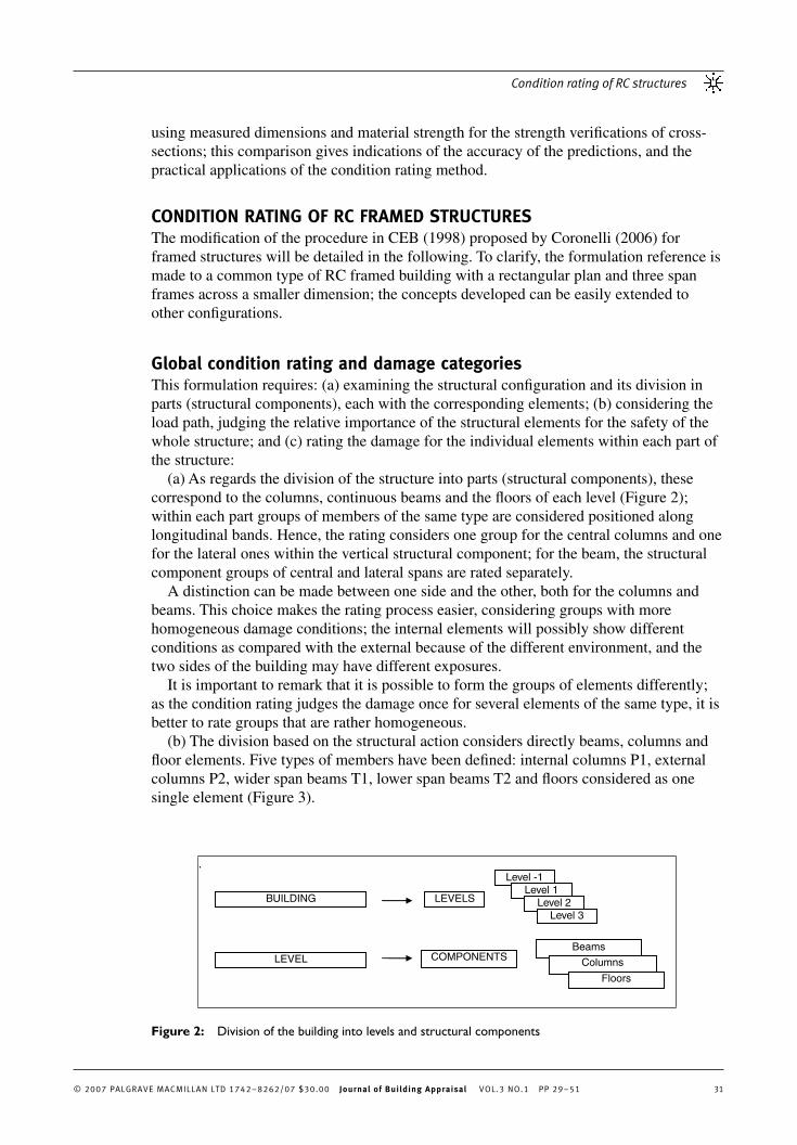
(a) As regards the division of the structure into parts (structural components), these correspond to the columns, continuous beams and the fl oors of each level ( Figure 2 ); within each part groups of members of the same type are considered positioned along longitudinal bands. Hence, the rating considers one group for the central columns and one for the lateral ones within the vertical structural component; for the beam, the structural component groups of central and lateral spans are rated separately.
A distinction can be made between one side and the other, both for the columns and beams. This choice makes the rating process easier, considering groups with more homogeneous damage conditions; the internal elements will possibly show different conditions as compared with the external because of the different environment, and the two sides of the building may have different exposures.
It is important to remark that it is possible to form the groups of elements differently; as the condition rating judges the damage once for several elements of the same type, it is better to rate groups that are rather homogeneous.
(b) The division based on the structural action considers directly beams, columns and fl oor elements. Five types of members have been defi ned: internal columns P1, external columns P2, wider span beams T1, lower span beams T2 and fl oors considered as one single element ( Figure 3 ).
.Level -1
Level 1 Level 2
Level 3
BUILDING
LEVEL COMPONENTS Beams
Columns
Floors
LEVELS
Figure 2: Division of the building into levels and structural components

Coronelli
© 2007 PALGRAVE MACMILLAN LTD 1742–8262/07 $30.00 Journal of Building Appraisal VOL.3 NO.1 PP 29–5132
The general criterion is to give more importance to columns bearing higher actions, wider span beams or beams with higher loads: the columns at lower storeys and the internal columns (P1) compared with the external members (P2); wider span beams T1 having higher internal moments than the others (T2); the roof beams often bearing lower loads rather than beams at lower levels inside the building.
Moreover, the effect of the failure of an individual element has been taken into consideration; for instance, a column failure is brittle and could trigger the incremental collapse of more parts of the structure, and must be considered more important than a beam or fl oor failure; accordingly, the failure of a fl oor would have limited effects as compared with a beam failure.
(c) It is necessary to foresee all the possible damage types a priori ; their extension and intensity on the structure at study are considered, on the basis of visual observation and experimental measurements, and classifi ed using numerical indexes that will be defi ned in the following. The tables are used for the damage factors proposed by CEB (1998) , after adapting these values to the type of elements in each structural component and to the effects of each damage type.
On the basis of this observation and rating of elements, a rating function F is calculated for each structural component. The general expression for the rating function is the sum of the numerical values that consider each type of damage:
The sum is extended to all N damage types encountered; the individual factors have the
following meaning:
V Di total value of the index for the i th damage type, defi ned by the product of the factors, indicating the danger of the damage, the structural importance of the element,
–
(1)(1)
Figure 3: Structural scheme and elements
Condition rating of RC structures
© 2007 PALGRAVE MACMILLAN LTD 1742–8262/07 $30.00 Journal of Building Appraisal VOL.3 NO.1 PP 29–51 33
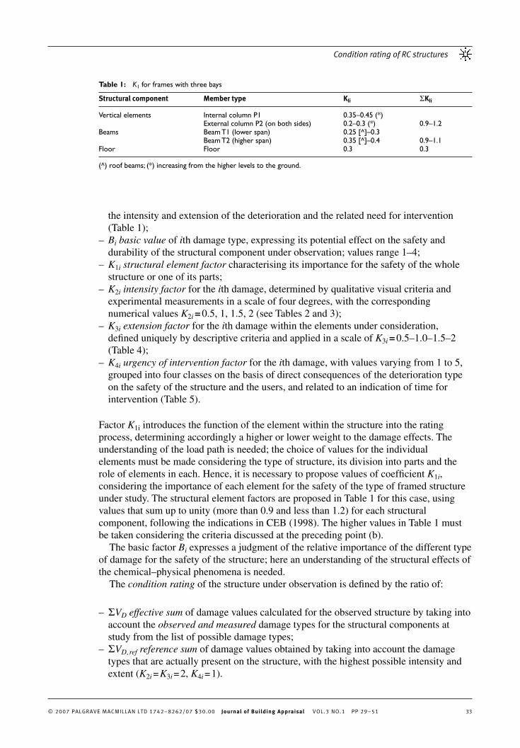
the intensity and extension of the deterioration and the related need for intervention ( Table 1 ); B i basic value of i th damage type, expressing its potential effect on the safety and durability of the structural component under observation; values range 1 – 4; K 1 i structural element factor characterising its importance for the safety of the whole structure or one of its parts; K 2 i intensity factor for the i th damage, determined by qualitative visual criteria and experimental measurements in a scale of four degrees, with the corresponding numerical values K 2 i = 0.5, 1, 1.5, 2 (see Tables 2 and 3 ); K 3 i extension factor for the i th damage within the elements under consideration, defi ned uniquely by descriptive criteria and applied in a scale of K 3 i = 0.5 – 1.0 – 1.5 – 2 ( Table 4 ); K 4 i urgency of intervention factor for the i th damage, with values varying from 1 to 5, grouped into four classes on the basis of direct consequences of the deterioration type on the safety of the structure and the users, and related to an indication of time for intervention ( Table 5 ).
Factor K 1i introduces the function of the element within the structure into the rating process, determining accordingly a higher or lower weight to the damage effects. The understanding of the load path is needed; the choice of values for the individual elements must be made considering the type of structure, its division into parts and the role of elements in each. Hence, it is necessary to propose values of coeffi cient K 1 i , considering the importance of each element for the safety of the type of framed structure under study. The structural element factors are proposed in Table 1 for this case, using values that sum up to unity (more than 0.9 and less than 1.2) for each structural component, following the indications in CEB (1998) . The higher values in Table 1 must be taken considering the criteria discussed at the preceding point (b).
The basic factor B i expresses a judgment of the relative importance of the different type of damage for the safety of the structure; here an understanding of the structural effects of the chemical – physical phenomena is needed.
The condition rating of the structure under observation is defi ned by the ratio of:
� V D effective sum of damage values calculated for the observed structure by taking into account the observed and measured damage types for the structural components at study from the list of possible damage types; � V D , ref reference sum of damage values obtained by taking into account the damage types that are actually present on the structure, with the highest possible intensity and extent ( K 2 i = K 3 i = 2, K 4 i = 1).
–
–
–
–
–
–
–
Table 1 : K 1 for frames with three bays
Structural component Member type K Ii � K Ii
Vertical elements Internal column P1 0.35 – 0.45 (*) External column P2 (on both sides) 0.2 – 0.3 (*) 0.9 – 1.2 Beams Beam T1 (lower span) 0.25 [^] – 0.3 Beam T2 (higher span) 0.35 [^] – 0.4 0.9 – 1.1 Floor Floor 0.3 0.3
(^) roof beams; (*) increasing from the higher levels to the ground.
Coronelli
© 2007 PALGRAVE MACMILLAN LTD 1742–8262/07 $30.00 Journal of Building Appraisal VOL.3 NO.1 PP 29–5134
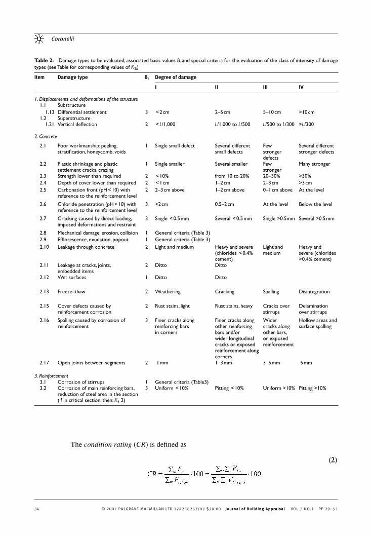
The condition rating ( CR ) is defi ned as
(2)(2)
Table 2 : Damage types to be evaluated, associated basic values B i and special criteria for the evaluation of the class of intensity of damage types (see Table for corresponding values of K 2 i )
Item Damage type B i Degree of damage
I II III IV
1. Displacements and deformations of the structure 1.1 Substructure 1.13 Differential settlement 3 < 2 cm 2 – 5 cm 5 – 10 cm >10 cm 1.2 Superstructure 1.21 Vertical defl ection 2 < L /1,000 L /1,000 to L /500 L /500 to L /300 > L /300 2. Concrete
2.1 Poor workmanship: peeling, stratifi cation, honeycomb, voids
1 Single small defect Several different small defects
Few stronger defects
Several different stronger defects
2.2 Plastic shrinkage and plastic settlement cracks, crazing
1 Single smaller Several smaller Few stronger
Many stronger
2.3 Strength lower than required 2 < 10% from 10 to 20% 20 – 30% >30% 2.4 Depth of cover lower than required 2 < 1 cm 1 – 2 cm 2 – 3 cm >3 cm 2.5 Carbonation front (pH < 10) with
reference to the reinforcement level 2 2 – 3 cm above 1 – 2 cm above 0 – 1 cm above At the level
2.6 Chloride penetration (pH < 10) with reference to the reinforcement level
3 >2 cm 0.5 – 2 cm At the level Below the level
2.7 Cracking caused by direct loading, imposed deformations and restraint
3 Single < 0.5 mm Several < 0.5 mm Single >0.5 mm Several >0.5 mm
2.8 Mechanical damage: erosion, collision 1 General criteria ( Table 3 ) 2.9 Effl orescence, exudation, popout 1 General criteria ( Table 3 ) 2.10 Leakage through concrete 2 Light and medium
Heavy and severe (chlorides < 0.4% cement)
Light and medium
Heavy and severe (chlorides >0.4% cement)
2.11 Leakage at cracks, joints, embedded items
2 Ditto Ditto
2.12 Wet surfaces 1 Ditto Ditto
2.13 Freeze – thaw 2 Weathering Cracking Spalling Disintegration
2.15 Cover defects caused by reinforcement corrosion
2 Rust stains, light Rust stains, heavy Cracks over stirrups
Delamination over stirrups
2.16 Spalling caused by corrosion of reinforcement
3 Finer cracks along reinforcing bars in corners
Finer cracks along other reinforcing bars and/or wider longitudinal cracks or exposed reinforcement along corners
Wider cracks along other bars, or exposed reinforcement
Hollow areas and surface spalling
2.17 Open joints between segments 2 1 mm 1 – 3 mm 3 – 5 mm 5 mm 3. Reinforcement 3.1 Corrosion of stirrups 1 General criteria (Table3) 3.2 Corrosion of main reinforcing bars,
reduction of steel area in the section (if in critical section, then: K 4 2)
3 Uniform < 10% Pitting < 10% Uniform >10% Pitting >10%

Condition rating of RC structures
© 2007 PALGRAVE MACMILLAN LTD 1742–8262/07 $30.00 Journal of Building Appraisal VOL.3 NO.1 PP 29–51 35
Equation (2) can be written, separating the sum M of the factors related to damage, from the factor K 1 related to the element and structural safety of the system:
The values of condition rating are divided into six deterioration classes, with an indication of the necessary intervention ( Table 6 ). The numerical values of condition rating corresponding to each class have been determined by simulation, that is, by generation and evaluation of about 150 random combinations of damage types and related damage values from Tables 1 – 4 .
(3)(3)
Table 3 : Factor K 2 i — general criteria for the intensity degree of a damage type
Degree Criterion K 2 i
Low — initial Damage of small size, generally appearing on single localities of a member
0.5
Medium — propagating Damage is of medium size, confi ned to single localities, or damage is of small size appearing on few localities or on a small area of a member (eg < 25%)
1.0
High — active Damage is of large size, appearing on many localities or on a greater area of a member ( 25 and 75%)
1.5
Very high — critical Damage is of a very large size, appearing on a major part of a member (>50%)
2.0
Table 4 : Factor K 3 i — general criteria for the extent of a damage type
Criterion K 3 i
Damage is confi ned to a single unit of the same type of member 0.5 Damage is appearing on several units (eg less than 1/4) of the same type of member 1.0 Damage is appearing on the major part of units (eg 1/4 to 3/4) of the same type of member
1.5
Damage is appearing on the great majority of units (more than 3/4) of the same type of member
2.0
Table 5 : Factor K 4 i — to stress the urgency of intervention
Criterion K 4 i
Intervention is not urgent because the damage does not impair either the overall safety and/or durability (service life) of the structure or the durability of the affected member
1
Damage must be repaired within a period not longer than fi ve years, to prevent further impairment of the overall safety and/or durability of the structure, or, solely, the durability of the affected member exposed to the aggressive attack
2 – 3
Immediate repair is required, as the damage is already jeopardising the overall safety and/or durability of the structure (especially in aggressive environment), or, if there is direct danger to people from falling pieces of disintegrated concrete
3 – 5
Temporary propping or limitation of traffi c loads is required 5

Coronelli
© 2007 PALGRAVE MACMILLAN LTD 1742–8262/07 $30.00 Journal of Building Appraisal VOL.3 NO.1 PP 29–5136
(c) Following CEB (1998) , the potential types of damage to determine M m , ref (see Equation (4)) are taken as shown in Tables 2 – 4 ; an example for a beam is shown in Table 7 .
In the formulation presented by CEB (1998) after calculating the rating function F or each structural component, the Condition Rating in Equation (3) is the ratio between the sum of the rating functions of all components of the structure and the sum of the reference values of these functions. This approach is defi ned here as global condition rating.
It is interesting to note that a condition rating of each level is possible, by limiting the sums of the rating functions to that portion of the structure; a judgment on the deterioration conditions of the different levels is thus possible; this formulation is adopted in the following for the global condition rating.
Other geometrical characteristics of the building can be refl ected by the choice of the portions over which the sums are extended; for instance, a nonregular plan with different bodies might lead to a corresponding defi nition of different parts and evaluating the rating of each.
Table 6 : Deterioration classes
Deterioration class
Description of the condition, necessary intervention, deterioration examples
Rating � R
I No defect, Only construction defi ciencies. 0 – 5 0.3 Action : No repair, only regular maintenance needed. Examples : geometrical irregularities, aesthetic imperfections, discolouring
II Low degree deterioration, which only after a long period of time might be the
cause for reduced serviceability or durability of the affected structural component, if not repaired in proper time
3 – 10 0.4
Action : Deteriorated locations can be repaired with low costs as part of regular maintenance works
Examples : Local cracks, smaller defi ciencies resulting from bad concreting practice, locally cover too thin
III Medium degree deterioration, which can be the cause for reduced serviceability
and durability of the affected structural component, but still not requiring any limitation of use of the structure
7 – 15 0.5
Action : Repair in reasonably short time is needed Examples : Cracking, greater defi ciencies resulting from bad concreting practice, very thin cover on mostly wet areas, defect of waterproofi ng
IV High degree deterioration, reducing the serviceability and durability of the
structure, but still not requiring serious limitation of use 15 – 25 0.6
Action : Immediate repair to preserve the designed serviceability and durability Examples : Reinforcement corrosion on main carrying members
V Very heavy deterioration, requiring limitation of use, propping of most critical
components, or other protective measures 22 – 35 0.7
Action : Immediate repair and strengthening of the structure is required, or the carrying capacity shall be adequately reduced
Examples : Heavy corrosion of reinforcement in the main carrying members, wide cracks because of overloading
VI Critical deterioration, requiring immediate propping of the structure and strong
limitation of use, for example, closing �30 0.8
Action: Immediate and extensive rehabilitation works are needed; however, the design serviceability and use of the structure, as well as acceptable remaining service can no more be achieved with economic costs
Examples : As Class V, plus lower level of safety

Condition rating of RC structures
© 2007 PALGRAVE MACMILLAN LTD 1742–8262/07 $30.00 Journal of Building Appraisal VOL.3 NO.1 PP 29–51 37
Local condition rating The condition rating is evaluated here for each element belonging to the three structural components considered (column, beam and fl oor):
100100,
= =∑∑
i irefD
i iD
ref
m
V
V
F
FCR
that is by the ratio of the rating function of the element and its reference value. Different from what is shown in Equations (1) – (4), the rating function F m is calculated on the basis of the observation of the m th element within the part of the structure, and not for the groups of elements of the global formulation; hence, factors K 2 i , K 3 i , K 4 i are determined here from the conditions and measurements on one specifi c element.
Evaluation of remaining carrying capacity Taking R as the resistance of the structural element and S as the load effect, the strength deterioration factor � is determined by the expression:
where:
� is the the strength deterioration factor for the element; B R is the capacity reduction factor, the ratio between the true and the nominal strength of a critical section of an element, determined according to design rules, without considering strength deterioration; � R is the deterioration factor, with values ranging from 0.3 to 0.8 in relation to the condition rating value obtained for the element (see Table 6 );
––
–
(5)(5)
(6)(6)
Table 7 : Evaluation of M m, ref of a beam considering all possible defects
Element Item Damage B i K 2 i K 3 i K 4 i V d /K 1 M m , ref
Beam ( K 1 i =0.6) 2.1 Poor workmanship 1 2 2 1 4 116 2.2 Cracking (shrinkage, etc) 1 2 2 1 4 2.3 Strength lower than required 2 2 2 1 8 2.4 Depth of cover lower than required 2 2 2 1 8 2.5 Carbonation front 2 2 2 1 8 2.7 Cracking — direct loading 3 2 2 1 12 2.8 Mechanical damage 1 2 2 1 4 2.9 Effl orescence 1 2 2 1 4 2.10 Leakage 2 2 2 1 8 2.11 Leakage at cracks, joints, embedded items 2 2 2 1 8 2.12 Wet surfaces 1 2 2 1 4 2.13 Freeze – thaw 2 2 2 1 8 2.15 Cover defects caused by reinforcement
corrosion 2 2 2 1 8
2.16 Spalling caused by corrosion of reinforcement
3 2 2 1 12
3.1 Stirrup corrosion 1 2 2 1 4 3.2 Corrosion of bars (area reduction) 3 2 2 1 12

Coronelli
© 2007 PALGRAVE MACMILLAN LTD 1742–8262/07 $30.00 Journal of Building Appraisal VOL.3 NO.1 PP 29–5138
V R is the coeffi cient of variation of strength, to be determined on the basis of the tests and inspections data on the materials; � C is the target value of the minimum acceptable safety level, that is, reliability coeffi cient.
B R is the capacity reduction factor for structures with no degradation, taking into consideration the uncertainties for unknown conditions in the fi eld: variation of geometrical dimensions, strength of the materials, uncertainties related to the structural analysis. Values for B R are determined according to ACI (2004) :
B R = 0.9 for bending; B R = 0.85 for shear; B R = 0.7 for combined bending and axial load.
The coeffi cient V R is chosen as follows:
V R = V RA = coeffi cient of variation for steel, from tests, for elements where failure is determined by the breaking of the steel bars in tension; V R = V RC = coeffi cient of variation for concrete, from tests, for elements where failure is determined by the crushing of the concrete in compression.
The factor � conceptually represents the capacity reduction factor in deteriorated conditions. The exponential factor in Equation (6) considers a reduction depending on the deterioration level ( � R ), the uncertainties on all the inspection data ( V R ), and the safety level chosen for the structure ( � C is variable from 3.3 to 4.3 — CEN, 2001 ). The values of � can vary from 0.5 in the case of very deteriorated structures with no maintenance and regular inspection, to values greater than 1 in the case of structures in good conditions and undergoing accurate inspections.
The safety verifi cations will be in the form:
where S d is the design value for the load effect and R n the nominal strength value for the limit state under consideration ( Znidaric and Znidaric, 1994 ), or the characteristic value of strength in the Limit State method.
The strength deterioration factor can be obtained by using the condition rating value from the global or the local formulation; in the following the latter are used as they are closer to the local characteristics of the structural verifi cations performed for each element.
CASE STUDY — RC INDUSTRIAL BUILDING The industrial building chosen as a case study is part of a group built in the centre of Milan by the Societ á Umanitaria in 1950. It functioned as a technical school with industrial machinery until 1980 when the building was completely abandoned, with no maintenance to date.
–
–
–––
–
–
(7)(7)

Condition rating of RC structures
© 2007 PALGRAVE MACMILLAN LTD 1742–8262/07 $30.00 Journal of Building Appraisal VOL.3 NO.1 PP 29–51 39
Preliminary study and visual inspection The building is made of three storeys above ground ( Figure 4 ) with one below ground level; the plan dimensions measure 46 × 22 m. The structure is RC with fl oors made by joists and slab with a hollow core brick for thermal and acoustic insulation. The basic structural unit is a frame with three spans, repeated 9 times along the longitudinal axis of the building at a distance of 4.5 m; the beams in the three upper fl oors have an increased cross-section depth at the beam – column joints, whereas at the ground fl oor they are prismatic. The side and central spans are 7.5 and 5.5 m, respectively; the inter-storey height is 4.3 m.
The gravity load path ( Figure 5 ) follows the one-way fl oors supported by the main beams; two central and two lateral columns transfer the load to the base of the building. No inspection was possible for the foundations, but no evidence of differential settlements was found in the building. The design of multi-storey buildings in the Milan area traditionally takes into account low horizontal forces for wind and seismic effects, entirely carried by RC walls in correspondence of the stairs. One RC core is positioned at the north of the plan, with two shear walls at the opposite end.
Accurate visual inspection of the damage was performed as a fi rst step; the urban aggressive environment and the long period without maintenance are the causes of several serious damage phenomena. The structural elements exposed on the external surface of the building show spalling of the concrete cover and very serious corrosion of the bars: in particular, at the base of the columns, at the surface under and at the side of the beams ( Figure 6 ) and at the beam – column joints ( Figure 7 ). The members inside the building show small signs of active corrosion (rust stains); leakage of water from the roof, wet surfaces and effl orescence are evidently on the increase from the lower level to the last level ( Figure 8 ).
Figure 4: Side of the building (South)

Coronelli
© 2007 PALGRAVE MACMILLAN LTD 1742–8262/07 $30.00 Journal of Building Appraisal VOL.3 NO.1 PP 29–5140
Figure 5: Load path of the framed scheme
Figure 6: Corrosion beneath a beam

Condition rating of RC structures
© 2007 PALGRAVE MACMILLAN LTD 1742–8262/07 $30.00 Journal of Building Appraisal VOL.3 NO.1 PP 29–51 41
Material properties and geometry The following tests were performed to determine the material properties:
rebound hammer tests for the concrete; concrete cores and compression tests; cutting of bar samples and tension tests.
–––
Figure 7: Beam – column joint and beam corrosion
Figure 8: Leakage and effl orescence — interior

Coronelli
© 2007 PALGRAVE MACMILLAN LTD 1742–8262/07 $30.00 Journal of Building Appraisal VOL.3 NO.1 PP 29–5142
To measure the deterioration processes for the concrete and steel:
carbonation depth measurements; cover depth measurements; potential mapping to determine the active corrosion areas; resistivity mapping for an estimate of the corrosion rate.
The geometry of the members was measured accurately, and so was the amount of reinforcement by a rebar-locator, exposing the bars where necessary.
The measured material properties are given in Table 8 . The carbonation depth on the external surface is 23 mm, with a coeffi cient of variation 0.32. The average cover depth measured for columns inside the building was 35 mm. The resistivity measurements and the potential mapping inside the building at the ground and second fl oors did not measure signs of relevant active corrosion.
Condition rating
Condition rating — Local results For each of the four levels, 28 beams, 40 columns and 24 fl oor spans must be considered. For each m th element the sums of damage indices M m , M m , ref are calculated and, hence, the condition rating. The list of potential damages with the corresponding intensity, extension and urgency of intervention factors are given in Tables 2 – 4 . An example of the calculation of M m , ref has been shown in Table 7 . Table 9 shows the evaluation of M m for one internal beam at the fi rst fl oor of the building, with the condition rating CR of the element calculated as a ratio to M m , ref equal to 12.5 per cent. The observation of the
––––
Table 9 : Damage and evaluation of M m for an internal beam, fi rst level of the building
Element Item Damage B K 2i K 3i K 4i V di / K 1i M m = � V di / K 1i
Internal beam no. 3 2.5 Carbonation front 2 2 1.5 2 12 16 2.9 Effl orescence 1 1 1 1 1 2.10 Leakage 2 0.5 0.5 1 0.5 2.11 Leakage at joints 2 1.5 0.5 1 1.5 2.12 Wet surface 1 1 1 1 1 2.13 Freeze-thaw 2 0.5 0.5 1 0.5 2.15 Cover defects —
corrosion 2 0.5 0.5 1 0.5
Table 8 : Material strength tests
Rebound index (average)
Rebound index (COV) (%)
Strength — average (MPa)
Strength (COV) (%)
Rebound hammer Columns 35.6 12 34.0 Beams 30.6 11 24.7 Cores — compression 16.9 16 Steel — tension 384.6 2.3

Condition rating of RC structures
© 2007 PALGRAVE MACMILLAN LTD 1742–8262/07 $30.00 Journal of Building Appraisal VOL.3 NO.1 PP 29–51 43
numerical values in Table 9 shows that 75 per cent (12 of 16) of the sum of damage values is due to the carbonation front depth.
The same procedure is applied to all beams, columns and fl oors in the building. Associating a different colour to each deterioration class, evaluated according to Table 6 , the representation of local damage is given by means of condition rating maps, as shown in Figures 9 – 11 .
Examining these results, the more deteriorated zones can be recognised, and the conditions of different parts of the building compared, showing a marked difference between the internal and external elements. External beams ( Figure 9 ) at the ground level are in high damage conditions (IV), and reach very high and critical levels moving to the fl oors above. The internal beams show some conditions of medium-high damage (class III – IV) starting from the fl oor below the ground level; this situation spreads to all elements at the fi rst and second fl oors, while at the third fl oor all elements reach high and very high levels (IV and V).
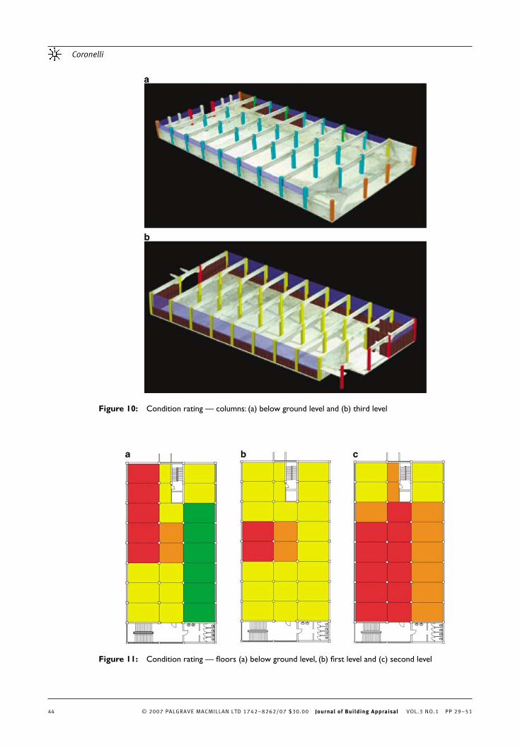
For columns ( Figure 10 ), very high and critical conditions (class V and VI) are present starting from the ground level on the short sides of the building (North and South), and with medium to high levels (class III – IV) along the East and West sides. The conditions of the internal columns are good (class I – II) up to the last fl oor, where medium – high damage conditions are present (class III – IV).
The fl oors ( Figure 11 ) show class III and IV conditions at the level below the ground level ( Figure 11a ), with a class V – VI zone at the north-west corner of the building. The fi rst level ( Figure 11b ) is entirely at class IV or even above, the second ( Figure 11c ) nearly entirely in class V and the third at critical conditions (VI).
Figure 9: Condition rating — beams: (a) second level and (b) third level
Coronelli
© 2007 PALGRAVE MACMILLAN LTD 1742–8262/07 $30.00 Journal of Building Appraisal VOL.3 NO.1 PP 29–5144
Figure 10: Condition rating — columns: (a) below ground level and (b) third level
Figure 11: Condition rating — fl oors (a) below ground level, (b) fi rst level and (c) second level
Condition rating of RC structures
© 2007 PALGRAVE MACMILLAN LTD 1742–8262/07 $30.00 Journal of Building Appraisal VOL.3 NO.1 PP 29–51 45
Summing up a strong deterioration is present for some members, beams and columns exposed to the environmental conditions outside the building. Inside the building deterioration of the horizontal structure, fl oors and beams grows moving upwards from one level to the other to the roof level. The fl oors below the ground level are in better condition, as compared to the other parts, with the exception of a limited area. The fi rst and second levels show much worse conditions; at the third level, high damage is present on nearly all elements.
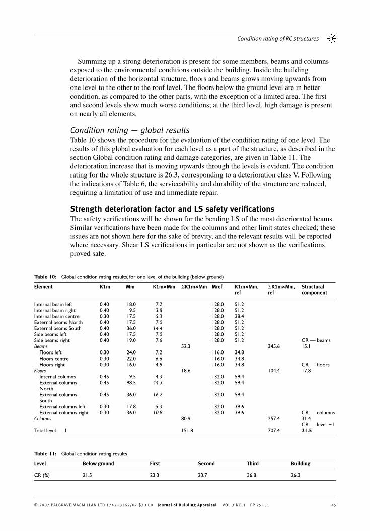
Condition rating — global results Table 10 shows the procedure for the evaluation of the condition rating of one level. The results of this global evaluation for each level as a part of the structure, as described in the section Global condition rating and damage categories, are given in Table 11 . The deterioration increase that is moving upwards through the levels is evident. The condition rating for the whole structure is 26.3, corresponding to a deterioration class V. Following the indications of Table 6 , the serviceability and durability of the structure are reduced, requiring a limitation of use and immediate repair.
Strength deterioration factor and LS safety verifi cations The safety verifi cations will be shown for the bending LS of the most deteriorated beams. Similar verifi cations have been made for the columns and other limit states checked; these issues are not shown here for the sake of brevity, and the relevant results will be reported where necessary. Shear LS verifi cations in particular are not shown as the verifi cations proved safe.
Table 10 : Global condition rating results, for one level of the building (below ground)
Element K 1 m Mm K 1 m × Mm � K 1 m × Mm M ref K 1 m × M m , ref
� K 1 m × M m , ref
Structural component
Internal beam left 0.40 18.0 7.2 128.0 51.2 Internal beam right 0.40 9.5 3.8 128.0 51.2 Internal beam centre 0.30 17.5 5.3 128.0 38.4 External beams North 0.40 17.5 7.0 128.0 51.2 External beams South 0.40 36.0 14.4 128.0 51.2 Side beams left 0.40 17.5 7.0 128.0 51.2 Side beams right 0.40 19.0 7.6 128.0 51.2 CR — beams Beams 52.3 345.6 15.1 Floors left 0.30 24.0 7.2 116.0 34.8 Floors centre 0.30 22.0 6.6 116.0 34.8 Floors right 0.30 16.0 4.8 116.0 34.8 CR — fl oors Floors 18.6 104.4 17.8 Internal columns 0.45 9.5 4.3 132.0 59.4 External columns North
0.45 98.5 44.3 132.0 59.4
External columns South
0.45 36.0 16.2 132.0 59.4
External columns left 0.30 17.8 5.3 132.0 39.6 External columns right 0.30 36.0 10.8 132.0 39.6 CR — columns Columns 80.9 257.4 31.4 CR — level − 1 Total level — 1 151.8 707.4 21.5
Table 11 : Global condition rating results
Level Below ground First Second Third Building
CR (%) 21.5 23.3 23.7 36.8 26.3

Coronelli
© 2007 PALGRAVE MACMILLAN LTD 1742–8262/07 $30.00 Journal of Building Appraisal VOL.3 NO.1 PP 29–5146
To evaluate the internal forces and moments, elastic analysis was performed for a three-dimensional frame fi nite element model; self-weight and a live load of 6 KN / m 2 (the minimum prescribed by the National code for industrial buildings) were imposed. The beam geometry and reinforcement are shown in Figure 12 .
Two different measures of strength are compared here:
strength calculated by the deterioration factor defi ned in the section Strength deterioration and LS safety verifi cations ( CR values); according to limit state assumptions, using measured dimensions and material strength ( LS ).
Beams of the third level are taken into consideration, where the highest deterioration class was reached ( Figure 9b ) with a coeffi cient � R = 0.8 for several elements, both exposed on the external facades and inside the building; these two positions will be indicated in the following as ‘ external beams ’ and ‘ internal beams ’ . Figures 6 and 8 show the damage conditions: in the former case, spalling and cross-sections losses are evident, whereas inside the building the consequences of heavy leakage are evident.
The strength deterioration factor of Equation (6) is evaluated by using the results of the tests on materials given in Table 8 ; a value � C = 3.8 has been used for the reliability index, following CEN (2001) for Ultimate Limit States, a period of 50 years and B R = 0.9 for bending failure.
For the LS verifi cations, the partial safety factors for materials were reduced because measured dimensions and material strength properties were used ( ISE, 1980 ):
� c = 1.25 (ductile fl exural behaviour); 1.35 (brittle structural behaviour); � s = 1.05.
As regards � c , a ductile type of failure is expected for the beams where only low or moderate corrosion has developed. An increased � c is taken for highly corroded elements
–
–
––
Figure 12: Beam geometry and reinforcement: A-A interior hogging moment section; B-B midspan section; C-C exterior section.

Condition rating of RC structures
© 2007 PALGRAVE MACMILLAN LTD 1742–8262/07 $30.00 Journal of Building Appraisal VOL.3 NO.1 PP 29–51 47
in order to consider the different structural action and possibility of brittle failures as a consequence of bond deterioration, heavy cross-section reductions, pitting of bars, etc.
According to the condition rating method, both the internal and external beams considered have reached the same damage level, and thus the same strength deterioration factor � is calculated in both cases ( Table 12a ). The reduced strength values are calculated by applying the strength reduction factor as shown in Table 12b, c .
The LS values for both beams are higher than those predicted by the condition rating; the two sets of values in the fi rst column of Table 12b and c , indicated as LS (1) and LS (2), differ due to the difference in tension in the cross-sections of the steel in tension in the two cases — no cross-section loss is considered inside the building.
The internal moments for the external beams are lower because of the position and smaller tributary area of these elements. The safety verifi cations indicate that the strength is exceeded for the mid-span section of the internal beam according to the CR; the LS method with measured cross-sections indicates that the whole structure is safe.
For comparison, one further set of strength values LS (3) is calculated for both beams, assuming a condition where both the top and bottom layers of the bars are corroded, with the same attack of the tension reinforcement of the external beam, that is, the worst level of corrosion shown in the structure. These values are quite close to those predicted by the CR.
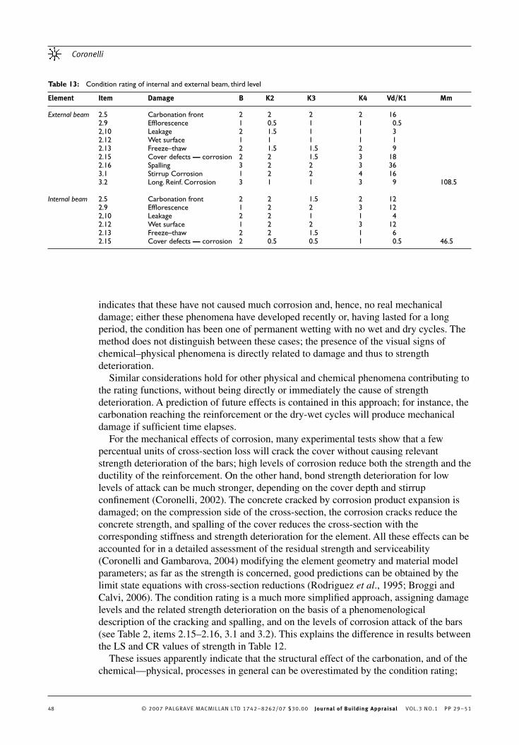
Discussion of results Observing the rating results for the external beams as an example (see Table 13 ), a large contribution in the rating function of the member is given by the carbonation of the concrete cover. According to Tables 2 and 7 , the maximum damage intensity is attained as soon as the front reaches the reinforcement, even if the steel itself is not corroding yet, or initial corrosion has only developed without signifi cant cross-section losses. As far as strength is concerned, a bar in these conditions is perfectly sound, but a high measure of damage is obtained by the condition rating.
In the rating of internal beams, a large part of the element damage functions is due either to wet surfaces or effl orescence as shown in Figure 8 . The visual observation
Table 12 : Bending strength LS for deteriorated beams (a) Condition rating strength deterioration factor � ; (b) external beam: LS (1) measured reduction of steel cross-section, brittle failure ( � c =1.35, � s =1.05); LS (3) both layers of reinforcement corroded; (c) Internal beam: LS (2) partial safety factors for measured material properties ( � c =1.25, � s =1.05); LS (3) both layers of reinforcement corroded
(a)
B R � R V RA � C �
0.9 0.8 0.03 3.8 0.822
(c)
Section M rd ( KNm) LS (2) M R n � · M Rd ( KNm) CR M rd ( KNm) LS (3) M sdu ( KNm)
Midspan 285.4 299.6 246.1 241.4 254 Fixed end C-C 447.15 477.9 392.6 378.0 287.8 Fixed end A-A 893.4 953.2 783.1 755.0 419
(b)
Section M rd ( KNm) LS (1) M R n � · M Rd ( KNm) CR M rd ( KNm) LS (3) M sdu ( KNm)
Midspan 242.2 299.6 246.1 241.4 127 Fixed end C-C 437 477.9 392.6 378.0 143.9 Fixed end A-A 876 953.2 783.1 755.0 209.5
Coronelli
© 2007 PALGRAVE MACMILLAN LTD 1742–8262/07 $30.00 Journal of Building Appraisal VOL.3 NO.1 PP 29–5148
indicates that these have not caused much corrosion and, hence, no real mechanical damage; either these phenomena have developed recently or, having lasted for a long period, the condition has been one of permanent wetting with no wet and dry cycles. The method does not distinguish between these cases; the presence of the visual signs of chemical – physical phenomena is directly related to damage and thus to strength deterioration.
Similar considerations hold for other physical and chemical phenomena contributing to the rating functions, without being directly or immediately the cause of strength deterioration. A prediction of future effects is contained in this approach; for instance, the carbonation reaching the reinforcement or the dry-wet cycles will produce mechanical damage if suffi cient time elapses.
For the mechanical effects of corrosion, many experimental tests show that a few percentual units of cross-section loss will crack the cover without causing relevant strength deterioration of the bars; high levels of corrosion reduce both the strength and the ductility of the reinforcement. On the other hand, bond strength deterioration for low levels of attack can be much stronger, depending on the cover depth and stirrup confi nement ( Coronelli, 2002 ). The concrete cracked by corrosion product expansion is damaged; on the compression side of the cross-section, the corrosion cracks reduce the concrete strength, and spalling of the cover reduces the cross-section with the corresponding stiffness and strength deterioration for the element. All these effects can be accounted for in a detailed assessment of the residual strength and serviceability ( Coronelli and Gambarova, 2004 ) modifying the element geometry and material model parameters; as far as the strength is concerned, good predictions can be obtained by the limit state equations with cross-section reductions ( Rodriguez et al ., 1995 ; Broggi and Calvi, 2006 ). The condition rating is a much more simplifi ed approach, assigning damage levels and the related strength deterioration on the basis of a phenomenological description of the cracking and spalling, and on the levels of corrosion attack of the bars (see Table 2 , items 2.15 – 2.16, 3.1 and 3.2). This explains the difference in results between the LS and CR values of strength in Table 12 .
These issues apparently indicate that the structural effect of the carbonation, and of the chemical — physical, processes in general can be overestimated by the condition rating;
Table 13 : Condition rating of internal and external beam, third level
Element Item Damage B K2 K3 K4 Vd/K1 Mm
External beam 2.5 Carbonation front 2 2 2 2 16 2.9 Effl orescence 1 0.5 1 1 0.5 2,10 Leakage 2 1.5 1 1 3 2.12 Wet surface 1 1 1 1 1 2.13 Freeze – thaw 2 1.5 1.5 2 9 2.15 Cover defects — corrosion 2 2 1.5 3 18 2.16 Spalling 3 2 2 3 36 3.1 Stirrup Corrosion 1 2 2 4 16 3.2 Long. Reinf. Corrosion 3 1 1 3 9 108.5 Internal beam 2.5 Carbonation front 2 2 1.5 2 12 2.9 Effl orescence 1 2 2 3 12 2,10 Leakage 2 2 1 1 4 2.12 Wet surface 1 2 2 3 12 2.13 Freeze – thaw 2 2 1.5 1 6 2.15 Cover defects — corrosion 2 0.5 0.5 1 0.5 46.5
Condition rating of RC structures
© 2007 PALGRAVE MACMILLAN LTD 1742–8262/07 $30.00 Journal of Building Appraisal VOL.3 NO.1 PP 29–51 49
the strength values predicted by the LS equations appear to be conceptually correct. It is remarkable that assuming both layers of bars to be corroded in the beams (a virtual assumption of the worst possible case that was not actually present in the building), the strength values of the LS (3) method are nearly coincident with the condition rating predictions.
Finally, it must be noted that the CR values in the above two cases are different (CR = 46.6 for the internal beam, and 109 for the external), but the � R is the same in both cases ( = 0.8 for CR>30). To obtain different strength deterioration values, a different correspondence of � R and CR should be defi ned. The strength deterioration factor of the Condition Rating method shown here provides a conservative measure of strength; all possible effects of the damage phenomena are covered, with a prediction of their possible evolution and future mechanical effects. This aspect seems adequate for use in the maintenance and repair of structures, anticipating the most troublesome events and effects; it is too conservative for the assessment of the actual conditions of a structure.
Final considerations on the case study The exterior of the building has been exposed to the urban environment for over 50 years; the penetration of water from the roof inside the building started less than 20 years ago, after the building was abandoned. The visual examination of the structure reveals degradation phenomena that are different outside and inside the building: strong corrosion damage for members exposed to the exterior environmental attack, and very heavy leakage effects inside the building starting from the roof level, with little or no active corrosion.
The same pattern is revealed by the local condition rating of the building, together with an increasing damage level moving from the ground to the upper levels. The global condition rating shows the latter phenomenon, and a generally high level of damage to the building.
The condition rating maps furnish a numerical index associated to the conditions of different parts and elements of the building, with the opportunity to differentiate and compare them within a maintenance and repair process. Both these local and global condition ratings indicate that the serviceability and durability of the structure are reduced, requiring a limitation of use and immediate repair.
The strength verifi cations indicate that some elements inside the building are unsafe, according to the CR strength deterioration factor, whereas the LS method indicates that the safety requirements are respected in all members. Similar results, not shown here, have been obtained also for the columns. One particular aspect of the structure under study is that the more damaged the elements on the outside of the building are also less loaded, and hence the verifi cations are fulfi lled.
A fi nal remark is that one of the most deteriorated parts of the building are the beam – column joints, showing wide open cracks and spalled concrete on the East side, opened by the splicing of the reinforcement at these locations; as the amount of reinforcement is double, the reinforcement corrosion causes a very strong splitting pressure and damage. Considering the horizontal loads carried by the shear walls, the reduced strength of these areas was taken into consideration only with respect to axial forces; this type of damage would be a major problem when assessing a corroded structure with moment resisting frames for seismic loading, if the splices were at the ends of the columns.

Coronelli
© 2007 PALGRAVE MACMILLAN LTD 1742–8262/07 $30.00 Journal of Building Appraisal VOL.3 NO.1 PP 29–5150
CONCLUSIONS The formulation of a Condition Rating method originally proposed for bridges by CEB (1998) has been adapted to assess the global safety of buildings with RC frames and fl oors, a structural scheme common to many industrial and residential buildings. In addition, the method has been further developed to evaluate damage and strength deterioration conditions locally, for each element in the structure.
A case study for an industrial building has been shown. The global approach gives a general indication on the need to limit the use of and to repair the structure. The local formulation furnishes more detailed indications for maintenance and repair of different parts and members. The strength deterioration calculations by the condition rating method prove to be conservative, compared to the limit state method for existing structures, the latter using measured geometry and material properties.
The method is based both on visual observations and measurements, relying partly on the experience and subjective evaluations of the operators. Therefore, its application requires a sound knowledge of the deterioration phenomena, their morphology and visible indicators and their possible structural consequences.
The conservative measure of strength obtained, using the present version of the method, makes it useful for the preliminary assessment of structures: the most deteriorated parts and elements in the building are detected and a fi rst estimate of their strength is obtained, thus serving as a basis for more detailed investigations.
The Condition Rating has been formulated to consider the damage caused by physical and chemical phenomena; the developments of the method should consider more carefully the relation between the different stages of these deterioration processes and the corresponding structural effects in order to obtain more accurate strength predictions. At present, the initiation of the corrosion phenomena or the presence of other physical and chemical phenomena leads to high strength deterioration estimates, which can be too conservative. These conclusions have been drawn by comparison with the limit state verifi cations using measured material properties and cross-sections. A more useful method of calibration would be to compare its results with load tests on the existing structure.
The method has a structure open to modifi cations in order to consider more complicated confi gurations in framed buildings or other types of structures; on the basis of the present knowledge for wide populations of bridges and simple frame and fl oor schemes in buildings, these further developments could yield useful and applicable methodologies.
Acknowledgements The collaboration with the Comune di Milano (Milan Municipality), Settore Edilizia Patrimoniale, in the person of Arch. Carmelo Maugeri is gratefully acknowledged. I thank Eng. Giacomo Tenerini and Eng. Emanuele Serventi who developed their MS Thesis on the case study presented in this paper, and also Professor Pietro Gambarova, Politecnico di Milano for the encouragement and critical review.
References ACI ( 2004 ) , ACI Building Code Requirements for Structural Concrete, 318M/318RM-279, Chapter 20 — Strength
evaluation of existing Structures .
Broggi , L . and Calvi , E . ( 2006 ) ‘ Sicurezza delle travi in C/A soggette a corrosione ’ , Master’s Thesis, Politecnico di
Milano, Dept. of Struct. Engng, October, 147pp .

Condition rating of RC structures
© 2007 PALGRAVE MACMILLAN LTD 1742–8262/07 $30.00 Journal of Building Appraisal VOL.3 NO.1 PP 29–51 51
CEB ( 1998 ) ‘ Strategies for testing and assessment of concrete structure ’ , Bulletin no. 243, May, 183pp .
CEN ( 2001 ) ‘ EC0 — EN 1990 EUROCODE ’ , Basis of Structural Design, Ref. No.prEN 1990:2001E, 89 pp .
Coronelli , D . ( 2002 ) ‘ Corrosion cracking and bond strength modelling for corroded bars in reinforced concrete ’ ,
Structure Journal, ACI , 99 (3) , 267 – 276 .
Coronelli , D . ( 2006 ) ‘ Condition rating for the evaluation of the safety of corroding RC structures ’ , Forde, M. (ed) 11th
International Conference on Structure, Faults and Repair , Engineering Tech. Press, Edinburgh, UK , on CD-
ROM .
Coronelli , D . and Gambarova , P . G . ( 2004 ) ‘ Structural assessment of corroding R/C beams: modelling guidelines ’ , ASCE
Journal of Structural Engineering , 130 8 (August) , 1214 – 1224 .
ISE ( 1980 ) ‘ Appraisal of existing structures ’ , The Institution of Structural Engineers (July) , 16 – 21 .
Rodriguez , J . , Ortega , L . and Casal , J . ( 1995 ) ‘ Load carrying capacity of concrete structures with corroded
reinforcement ’ , Forde, M. (ed) Fourth International Conference on Structure Faults and Repair , Engineering
Tech. Press, Edinburgh, UK , 189 – 199 .
Znidaric , J . and Znidaric , A . ( 1994 ) ‘ Evaluation of the carrying capacity of existing bridges ’ , Final Report, Institute for
Testing and Research in Materials and Structures, Ljubljana, Slovenia, 122pp .