CO CINCINNATI uunuunuuuuinm ad-aov94 730 general electric co cincinnati oh aircraft engine group pie...
133
AD-AOV94 730 GENERAL ELECTRIC CO CINCINNATI OH AIRCRAFT ENGINE GROUP pie 21/5 BACKUP CONTROL FOR A VARIABLE CYCLE ENGINE. (U) U NC JL 80 H B KAST F33615-TG-C-206 UNCLASSIFIED RSOAEGS5 AFAPL-TR-79-2069 NL m ; uunuunuuuuinm
Transcript of CO CINCINNATI uunuunuuuuinm ad-aov94 730 general electric co cincinnati oh aircraft engine group pie...

AD-AOV94 730 GENERAL ELECTRIC CO CINCINNATI OH AIRCRAFT ENGINE GROUP pie 21/5BACKUP CONTROL FOR A VARIABLE CYCLE ENGINE. (U)
U NC JL 80 H B KAST F33615-TG-C-206
UNCLASSIFIED RSOAEGS5 AFAPL-TR-79-2069
NL m; uunuunuuuuinm

AFAPL-TR-79-2069 LEVL BACKUP CONTROL FOR AVARIABLE CYCLE ENGINE
Phase II Final Report
Howard B. Kast
General Electric Company TIO Aircraft Engine Group
Cincinnati, Ohio 45215 FEB 6 1981
JULY 1980 C
TECHNICAL REPORT AFAPL-TR-79-2069
Final Report For Period 1 September 1977 - 16 April 1979
vi: IApproved for Public Release; Distribution Unlimited
. Aero Propulsion LaboratoryAir Force Wright Aeronautical Laboratories
9t Air Force Systems CommandWright-Patterson Air Force Base, Ohio 45433
71 .. ." ....

NOTICE
When Government drawings, specifications, or other data are used for any purposeother than in connection with a definitely related Government procurement operation,the United States Government thereby incurs no responsibility nor any obligationwhatsoever; and the fact that the government may have formulated, furnished, or inany way supplied the said drawings, specifications, or other data, is not to be re-garded by implication or otherwise as in any manner licensing the holder or anyother person or corporation, or conveying any rights or permission to manufactureuse, or sell any patented invention that may in any way be related thereto.
This report has been reviewed by the Office of Public Affairs (ASD/PA) and isreleasable to the National Technical Information Service (NTIS). At NTIS, it willbe available to the general public, including foreign nations.
This technical report has been reviewed and is approved for publication.
LESTER L. SMALL DAVID H. QUICK, Lt Col, USAFProject Engineer Chief, Components Branch
FOR THE COMMANDER
H. I. BUSHDeputy DirectorTurbine Engine Division
"If your address has changed, if you wish to be removed from our mailing list, orif the addressee is no longer employed by your organization please notify AFWAL/POTC,W-PAFB, OH 45433 to help us maintain a current mailing list".
Copies of this report should not be returned unless return is required by securityconsiderations, contractual obligations, or notice on a specific document.
'-

SECURITY CkWS14 FICATION OF THIS PAGE ("ahn Data !rntersd) __________________
(I jfEPORT DOCUMENTATION PAGE READ INSTRUCTIONSK BEFORE COMPLETING FORMIREPOR BER 12. GOVT ACCESSION No. 3. RECIPIENT'S CATALOG NUMBER
jAFAPI, 'R-7()-2p69-/D A~1 _________
4. 4 TL E (end Subtitle) .8L2O.8nAA PI 00 CO'<EREDSFinal echnical ep1't.
21 BAKU ONTROL FOR A .'ARIABLE CYCLE ENGINE, I Sep 77 - 16 AprP479 'C
PHASEII FIAL REORT . REPORT NUMBER
lioward 13.! Kast F31-6C28
General Electric Company-
Aircraft Engine Group Proj4':t 3p66_Cincinnati, Ohio 45219 Task 306603 W.U. 30660373
ICONTROLLING OFFICE NAME AND ADDRESS Z, REPORT DATE
Air Force Aero Propulsion Laboratory (TBC) '-IS. NUMBERO07 PAGESWright-Patterson AFB, Ohio 45433 117 1!14. MONITORING AGENCY NAME A AIDPRSSIf different from, Controlitng Office) IS. SECURITY CLASS. (of "ise
/ Unclassified
/c>~~1 -.~i~"-F-'IS.. DECL ASSIFICATION/ DOWNGRADINGISCHEDULEN/
I16 DISTRIBUTION STATEMENT (.f £hio Report)
ApQroved for public release; distribution unlimited.
17. DISTRIBUTION STATEMhENT (of the abstract entered in Block 20, if different from Report)
IS. SUPPLEMENTARY NOTES
19. KEY WORDS (Continu~e on reverse side if necessary' and identify by block number)
Backup ControlEmergency ControlGa&s Tu~rbine EnginesControl Reliability
20 ABSTRACT (Con tinue. on, reverse side If necessary and identify by block number)
The next generat ion of variable cycle aircraft engines (VCE) will have anlncr('ased c-omplexity associated with the number of controlled enginevariables, inherent cycle variability, and inlet-engine-exhaust controlintegration. This level of engine complexity and the expanding integration(if aircraft/engine controls causes a commensurate increase in the controlsystem complexity and capacity. Digital electronics has been identified asthe only viable means for meeting these significantly more sophisticated
DD I JAN 73 1473 EDITION OF I NOV 65 IS OBSOLETE
SECURITY CLASSIFICATION OF THIS PAGE (I01hen Data ,tE I d)
SECURITY CLASSIFICATION OF THIS PAGE( .n Dag& Enfeid)
requirements of the future VCE. Although recent digital electronic ad-vances promise new levels of reliability, this improvement is offset by theincreased circuitry of the more complex control. Especially in the case ofthe single-engine aircraft, it is recognized that such variable cycle en-gines should be equipped with a Backup Control for emergency use.
The results of Phase I, the trade studies, of the Backup Control for aVariable Cycle Engine program were reported earlier in AFAPL-TR-77-92. Thetrade studies were based on a single-engine aircraft, the JTDE-23 engine,an,; a full authority digital electronic primary control system. A minimumget-home capability was defined which included completing a takeoff, a mini-mum climb rate, deceleration from supersonic flight, windmill air start,minimum cruise range, wave-off, landing, and safe runway roll. Backup con-trol requirements were determined using theYF-17 aircraft data for thrust,the JTDE-23 engine computer model for the variables to be controlled, andthe F1OI engine and control model for ttansient performance. Seven backupcontrol approaches were selected for consideration from a list of 48 possi-bilities. These approaches included hydromechanical, electrical, fluidic,and a combination of electrical/hyd.omechanical technologies. Reliabilityestimates were made on six controls,and estimated performance, volume,weight, cost analyses and preliminary design studies were made in more de-tail on three of these approaches. A recommended approach was selected,namely the hydromechanical backup control using speed demand and fuel flowscheduling. This selection was based on the above analyses and studies,together with a comparison of the technologies, a comparison of parallel-versus series-type backup/primary control interface, and a tabulated evalu-ation of each backup control's advantages and disadvantages.
The recommended hydromechanical approach has been constructed, cali-brated and evaluated in a test cell. These evaluations included transientoperation and transfer from the primary control to the backup control andback to primary operation. Successful operation was achieved, providing testhardware which is intended for further validation through on-engine testing.
SECURITY CLASSIFICATION OF THIS PAGE(When Dots Entered)

FOREWORD
This report describes a design effort conducted by the General Electric
Company and sponsored by the Air Force Aero Propulsion Laboratory, Air Force
Systems Command, Wright-Patterson AFB, Ohio, under Project 3066, Task 03 and
Work Unit 73 with Lester L. Small, AFAPL/TBC, as Project Engineer.
The work reported herein was performed during the report period of
September 1, 1977 to April 16, 1979. R. E. Anderson was the General Electric
Program Manager; the technical work was performed under the direction of
Howard B. Kast, Engineering Manager. The Engineering Manager was assisted
by James E. Hurtle, Eugene T. Hill, and Robert P. Wanger.
This report cover, Phase II of the Backup Control for a Variable Cycle
Engine Program. Phase II involved the design, fabrication and bench testing
of the selected backup control. Phase I was completed in August 1977 and
covered the system trade studies and backup control selection. For the
technical results of Phase 1, refer to report No. AFAPL-TR-77-92, "Backup
Control for a Variable Cycle Engine, Phase I Interim Technical Report."
.... .., , , .j
iii

TABLE OF CONTENTS
I INTRODUCTION 1
II HARDWARE DESIGN 3
1 . Approach 32. Hydromechanical Backup Control Computer 6
3. Compressor Inlet Temperature Sensor 13
4. Fuel Valve 16
a. General 16h. Main Metering Valve 19
c. Flow Divider Valve 21
d. Cutoff Valve 21
e. Throttling Valve 21
'. Head Sensor 21
g. Servo Wash Screen 21
h. Stuart Pressurizing Valve 22
, ri, Valve Position Transducer 22
j Suma i'y: 24
5. Me eiing Valv e Mechanical Position Feedback 21
6. [raxnfer Logic 28
7. T,'ansfer Valve 30
8. Ovor pc.ed Switch and Valve 30
9. D tiv and Mounting Adapter 34
10. Pru:-3ure Divider 39
]. Off-Eigine Unit 39
12. Test Console 39
13. Production Hardware Design 39
III FABRICATION OF HARDWARE 46
i. Hyd'romechanical Computer and Compressor Inlet Temperature
Sensor 46
2. Fuel Valve Assembly 46
3. Transfer Valve Assembly 46
4. Drive Adapter, Mechanical Position Feedback and Overspeed
Assemblies 49
5. Off-Engine Unit and Backup Control Test Console 49
IV TEST PLANNING 54
1. Accelera t ion Schedule 54
2. Engine Model 54
3. Expected Transient Response 54
4. Expected Transfer Characteristics 64
V

TABLE OF CONTENTS (Concluded)
Page
V TEST RESULTS 68
1. Preliminary Calibration 68
2. Calibration 70
3. Backup Control Transient Response 74
4. Transfer to Backup Mode 80
5. Cyclic Endurance 97
6. Summary 99
VI CONCLUSIONS 100
VII RECOMMENDATIONS 101
APPENDIX A - SUBSYSTEM SAFETY ANALYSIS 103
APPENDIX B - CALIBRATION DATA S/N CAT 06021 108
REFERENCES 117
vi

LIST OF ILLUSTRATIONS
Figure Page
1 Functional Block Diagram of the Backup Control 4
2 Hvdromechanical Backup Control Schematic 5
3 Backup Control Computer Schematic 7
4 Partial Section Showing the Speed Sensor 9
5 Partial Section Showing the Metering Valve Servo 11
6 Partial Section Showing the PLA Cam and Several Levers 14
7 T2. 5 Sensor 15
8 Partial Section Showing the T2 .5 Servo 17
9 Fuel Valve Functional Block Diagram 18
10 Main Fuel Valve Schematic 20
11 LNVPT Position Transducer Schematic 23
12 Metering Valve Position Feedback Mechanism at the Fuel
Valve 25
13 Metering Valve Position Feedback Mechanism at the Computer 26
14 Feedback Cam and Follower 27
15 Primary/Backup Control Electrical Interface Block Diagram 29
16 Transfer Valve Schematic 31
17 Latching Solenoid Valve Drawing 32
18 Section of Transfer Valve Showing Switches 33
19 Overspeed Switch and Valve 35
20 Partial Section - Backup Control Drive 36
21 Sketch Showing Drive and Mounting Adapter 37
22 P. 3 Pressure Divider 38
23 Wf/PS3 Versus 76 NG at Various Levels of T2 .5 (Cam 2108) 40
24 Schematic of the Backup Control Off-Engine Unit 41
vii
II

IAST OF ILLUSTRATIONS (Continued)
Figure Page
25 Test Console Block Diagram 43
26 Test Console Metering Valve Circuit 44
27 Test Console Stator Circuit 45
28 Backup Control Computer and T2.5 Sensor Assembly 47
29 Detail Parts of the Fuel Valve 48
30 Transfer Valve Assembly 50
31 Drive Adapter, Mechanical Position Feedback Mechanism
and Overspeed Switch Detail Parts 51
32 Hydromechanical Portion of the Backup Control 52
33 Backup Control Test Console and Off-Engine Unit 53
34 Comparison of Accel Schedules 55
35 GE23/J1A3 Engine Model 56
36 GE23/JlA3 Loop Closure Functions 57
37 GE23/JlA3 Loop Closure Partials 58
38 Backup Control Governor, Nutcracker, and Metering Valve Servo
Mechanization 59
39 Linearized Block Diagram - Backup Control 60
40 Linearized Block Diagram - Backup Control, Takeoff Conditions
(PS -PO = 1050 psi) 63
41 Backup Control Calculated Governor Frequency Response 65
42 Fuel Flow Transient Upon Transfer 66
43 VCE Backup Control Preliminary Calibration Test Setup, Left
Side View 71
44 VCE Backup Control Preliminary Calibration Test Setup, Right
Side View 72
45 Comparison of Cam Schedules 73
viii
K__

LIST OF ILLUSTRATIONS (Continued)
Figure Page
46 Setup Used For Testing The Backup Control 75
47 View Showing The Computer Section of The Backup
Con t rol 76
48 F1OI Augimentor Fuel Pump and Filter Mounted To
Test Stund 77
49 Setup for Transient Testing of Backup Control 78
50 Trace of Backup Control at Steady State 79
51 Open-Loop Trace of Backup Control Acceleration and
Deceleration, 600 Control rpm/sec 8]
52 Open-Loop Trace of Backup Control Acceleration and
Deceileration, with Governor Cut-in, 600 Control rpm/sec 82
53 Closed-Loop Throttle Burst and Chop, Full ThrottleExcursion 83
54 Closed-Loop Throttle Burst and Cnop, Part Throttle Excursion 84
55 Open-Loop Governor Characteristics, Low Speeds, Showing the
Governor Hysteresis 85
56 Open-Loop Governor Characteristics, Mid Speeds, Showing the
Governor Hysteresis 86
57 Open-Loop Governor Characteristics, High Speeds, Showing the
Governor Hysteresis 87
5 Typical Frequency Response Traces 88
59 Backup Control Governor Frequency Response 89
60 Backup Control Variable Stator Frequency Response 90
61 Primary-to-Backup Transfer During Accel, Small Transient
Offset Error,/700 PLA 92
62 Primary-to-Backup Transfer During Accel, Large Transient
Offset Error, '700 PLA 93
63 Primary-to-Backup Transfer During Decel, Large Transient
Offset Error, -500 PLA 94
ix
, |I.

LISTr OF ILLUSTRATIONS (Concluded)
Figure Page
6-1 Primary- to-Backup Transfer During Accel, Ramp Transiento'5'0 Spteed/Sec, -600 PL 95
65 IHydrtiuechanical Overspeed Trace 96
x

LIST OF TABLES
Tat ' e Page
1 Temperature Sensor Calibration 69
2 Accel Schedule Data Taken Before and After the Endurance
Test 98
A-1 Backup Control Subsystem Safety Aralysis 104
xi

LIST OF SYMBOLS
B/U - Backup
BUC - Backup Control
F - Force
FADEC - Full Authority Digital Electronic Control
F/B - Feedback
JTDE - Joint Technology Demonstrator Engine
LVDT - Linear Variable Differential Transformer
LVPr - Linear Variable Phase Transformer
M - ',gnitude
MFC - in Fuel Control
NI - Fan rpm
NC - Control rpm
(or N2) - Gas (Gnerator rpr;
- Gas Generator rpm Rat-
P1 - Pump Discharge Pressure
- N ,t ,L i:; Valve Servo Pressure, Closing
PC2 - Metering Valve Servo Pressure, Opening
PLA - Power Lever Angle
PB - Boost Pump Pressure
Po - Case Pressure, Control
PS - Servo Pressure
PS3 or CDP - Compressor Discharge Pressure, Static
P'S 3 - Compressor Discharge Pressure, Static, Downstream of
Lhe Ratio Selector
PT2 - Inlet Pressure, Total
P - Throttling Valve Servo Pressure, Openingx
Py - Throttling Valve Servo Pressure, Closing
Q - Torque
S/V - Servovalve
T2. 5 - Compressor Inlet Temperature
VCE - Variable Cycle Engine
xiii

LIST OF SYMBOLS (Concluded)
Wf - Fuel Flow
Wf - Fuel Plow Rate
X or XMT - Metering V'alve Stroke
Wfrn - Fuel Flow, Main
c - Core Stator Angle
- Fan Stator Angle
AP- Metering Head
62.5- T2.5/518 .7' R
P - Specific Gravity
- Phase
xiv
SECTION i
INTRODUCTION
Today's military aircraft developments are addressing mission scenar-ios and application needs which place a wide range of different operating
conditiofn; on the propulsion system. The propulsion system requirementsresult in conflicting demands for optimizing the engine cycle selected for
the aircraft gas turbine. To meet this need, aircraft engine designers aremoving toward the use of gas turbines having an increased number of parame-
ters that are variable in flight. Ultimately this leads to the variable
cycle engine (VCE).
This program covered the design, fabrication, and testing of a BackupControl for a Variable Cycle Engine. This development effort is in supportof the evolving full-authority digital electronic control technology. The
backup control will provide the aircraft with an emergency get-home capabili-
tv in the event that the primary electronic control system is inoperative
due to :i failure or loss of electrical power.
Minimum get-home capability was defined as those functions which theaircraft/eigine systcn should be capable of performing while transferring
to, and while operating on, backup control. This capability included com-
pleting a takeoff, a minimum climb rate, deceleration from superscnic
flight, windmill air start, minimum cruise range, wave-off, landing, andsafe runway roil. Operational constraints were determined; these included
pilot action to (1) adjust for tolerable but undesirable overspeed or over-
temperature, (2) decelerate from supersonic speeds, and (3) execute wind-mill air starting. There will be no PLA restrictions at subsonic con-
ditions. The control environmental requirements are those of an aircraft
engine for Mach number 2.5 operation.
The need for the electronic engine control arises from the increased
complexity - i.e., increased number of controlled engine variables, inher-
ent cycle variability, inlet-engine-exhaust control integration - of thenext generation of sophisticated variable cycle engines. This increased
engine complexity, together with the expanding need for more complete
aircraft/engine control integration, demands a commensurate increase in the
complexity of the control system, whose capabilities must expand if it is
to provide stable, responsive, safe, and, precise engine control.
Digital electronics represents the only viable means of meeting the
significantly more sophisticated requirements of the variable cycle engine
of the future. With its inherent ability to time-share in the computation-
al section of the control, increasing requirement complexity yields a much
smaller increase in hardware compared to present control system mechaniza-tions. Digital electronics also lends itself to "hardening" to the air-
craft engine environment through hybrid construction, packaging, and en-
vironmental conditioning techniques.
As good as digital ulecLronicc are today, si gnlficant improvements
are being developed for <1ic:r.rion to gas turbine engine controls inorder to achieve the higher ],.,vels of control rtiability desired in1985-1990. It is reco,nized that the full-authority digital electronic
control for V('I is vet LCO be' tvaluated under field conditions and compared
to the reliabilitv recerd demonstrated by hydromechanical computer/con-trollers. This program was parsued In consideration of the significantlyincreased complexity of a VCE control system, and the current developmentstatus of the digital electronic approach. Since VCE propulsion systemsare rapidly becoming a reality, conducting thit- program to develop VCEbackup control technolo,;v 'n-; maLst timelv.
The prograi, consisted of two primary phases. The Phase I objectiveswere to conduct comprelhtnsive reliabiliiy, cost and performance evalua-tions on a variety of Eydromechanical, electronic and fluidic backup con-trol approaches for variable cycle engines having a primary electronic
control system and then to select a single approach for subsequent design,fabrication and testing. The objectives of Phase I[ were to conduct thedetailed design of the selected backup cor-trol, fabricate the control, andconduct bench testing in conjunction with a specifically designed backupcontrol test console.
Based on the results of the above analyses and comparisons, the paral-lel hydromechanical backup control, which demands NG and schedules Wf, wasrecommended for desi'n fabrication and test in Phase II of this program.This selection was made because it has the reduced unscheduled shutdownassociated with parallel systems and because the analyses showed this to bea lightweight economical apl;roach. It has the further advantage of repre-senting a construction technology inherently different from the primaryelectronic control, thus assuring a reduction in common-mode, single-causefailures.
The hydromechanical backup control, which is of the parallel or stand-by type, demands i" and schedules W- for the transient limit. The Wf anda schedules are computed based on Tz. and compressor dischargepressure (P.$3). This computer is very simllar to those used on many priorhydromechanical main fuel controls. A transfer valve is used to switch Wfand 6 c servo pressures from the primary servovalves to those of the backupservovalves.
This report covers Phase II of the Backup Control development for aVariable Cycle Engine. The material which follows includes hardware designand design drawings, a fabrication summary, the test plans and the test re-sults, followed by conclusions and recommendations.
2
,________________________,

SECTION TI
HARDWARE DES IGN
1. APPROACH
The backup control approach recommended for design, fabrication, andtesting is shown by a functional block diagram in Figure 1 and schematic-ally by Figure 2. This N(; - demanding and Wf- scheduling hydromechanicalbackup control was recommended based on the trade study conducted duringPhase I of this program.
The computation section and T2 .5 sensor are based on the equivalentportion of the J85-CE-21 Main Fuel Control. In the backup mode, Nc, is thedemanded parameter and closed-loop speed control is maintained by the hy-dromechanical governor. Accel/decel Wf limits are computed based on NG,T2.5, and PS3. The ;,c schedule is computed based on NC; and T2 .5 .
In the primary mode the backup control fuel valve and Rc servo flowsare blocked by a transfer valve. This approach minimizes interference andthe possible resulting backup control failures which could cause powero, s. ihe backup control is continuously computing the Wf and Sc limits,
thus tracking the engine. This is necessary to prevent stall, which couldbe caused by a jump in Wf during transfer.
Transfer can be initiated (1) by pilot action, (2) by loss of primarycontrol power, (3) by loss of primary control "good health" signal, or(4) by an overspeed condition as sensed by the backup control speed sensor.Transfer is accomplished Ly a current signal to the latching solenoid valve,which ports servo pressure to the piston driving the transfer valve spool.The latching solenoid was selected because it is compatible with (1) aircraftelectrical power and its possible interruptions, (2) the types of electricalsignals preferred for pilot action, (3) loss of primary control power, and(4) loss of the primary control "good health." Direct-acting hydro-mechanical overspeed protection is provided to guard against a stuck-openmetering valve. In the backup mode, the primary metering valve and Bcservo flows are blocked and the backup control has sole authority to controlthese variables.
The fuel valve is based on the design used for the Light Weight Fuel De-livery System program conducted by GE for the U.S. Navy. This valve wasdesigned to operate on fuel contaminated per Mil-E-5007C. The flow-dividingfunction for the vortex valves is also provided.
Some modifications to the above components were required to provide theadded functions needed by the backup control. A switch was added to thecomputer to initiate transfer to backup upon NG overspeed as sensed by thehydromechanical control. An overspeed valve was also added. This valve
3

-a
LL
zo0.
ccz
LLi
LL. C,
7W 0
> I 4
_____________T o__________

t
CT
-",,
t~~vA~ ~ 4-3 z~ y~
r1flcT~2: U' ~-c "'fl >~;11" ~t~ 0Jirt ~
-' - ~ ~j flr-Lr~-~-c-p ~vQA~.<~<~: ~'L 3~0 itt
I: ;r <Lsy 'K' ~ __ 2
HLI a
~ ~ tLLt~~- I-
4)
C
L t
,A----,/ C.)C'
_____ P ci
UI __ C
1' r _ __ .4r '.zr-~ L.± 9
a-- *. *. -t~~ Co
I -n I..(2121 .XvQ ~ 2 '
4 a4/~9~~ Cl
S -' ~ tXigfr~. bt
L '.44. 1g.-,
£ ~ __ ttJ~H
~
~ r A~
R: cZt 2 Lrt
- 1. _ _
t~c.'I
5
*"nata~q

tflduilat(e:; t~v t lro' t I 111Z VaIIL in c;1se( W1le1e (i. : l ~ 0 tl
The transfer valve was designed specifically for this program. As in-
dicated above, thi-; vlve determines whether the primary or backup servopressures conlrol the metering valve and c actuators. The transfer valvehas two switches. Tht first provides feedback to the primary control,notifying it that the transfer valve spool is in the backup position;the second turns on tho cockpit indicator light.
An ott-cn: el i iiciii unit and a test console were a!so dcsig ned.Thl, ott - i c oct I lI 11it inc l e a i-lI0-'f\ .Q't'i LO tI 't rilepilot's switch(es). The test console simulated the primary control duringbench testing of the b ackup control.
The various ,ubassem.blies involved are discussed in detail in the para-graphs that F .llow.
2. HYDROMECHANICAL BACKUP C -NTRL COM'UTEB
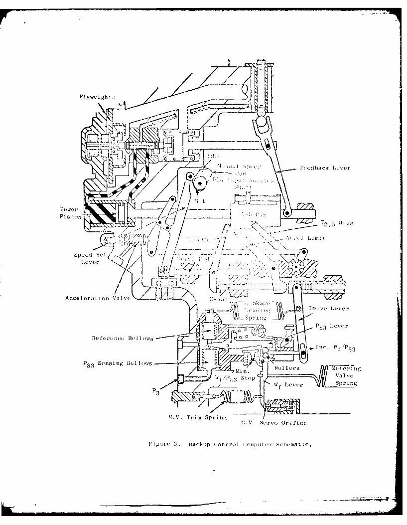
The backup control computer is shown schematically by Fi,.ure 3. In the
backup mode, this control computes a meterinF valve position for each en-gine operatiri coodition. Steady-state conditions are maintained in con-
junction with limiting and biasing functions, sHCl 05( as mrIiixiTInM RPM, ac-cel/decel limits, minimum W f and Ta. , !ias, which "re ilt Ir! so that a singleoutput -,I ' 2, .!):;I! IId.
Motion of the W ,,-,r occurs wh .: .e- _n unbalance exists in the mo-ments of force - i 'n o it. The po> it io:, oi the rollers represent.7 theproper value ot , as determined 'y the integration of thret engine
operating parameters; NG, PLA, and T A multiplying force- acte: nn the
rollers throuh a lever and is a func on of P absolute. The lever
system is arranged as a multiplier such t hat te load, P times the point
of load application, Wf /P 3, equals fuel flow. In equation forx,, it is:
PS3 :f S/PS3 W f
P is sensed by a bellows. The pressure times the bellow,; area pro-S3duces a force. The multiplying force is transmitted to the rollers by a
lever attached to the sepsing bellows. An evacuated bellows of equal ef-
fective area is mounted opposite the sensing bellous to serve as a refer-
ence. This second bellows also provide.; compensation fo undesired sensing
bellows movement that results from changes of temperature and pressure in
the bellows chamber. The bellows chamber is sealed off from the controlcasing and vented to the atmosphere through a small orifice. A ruptuI-d stns-ing bellows would fill the chamber with compressor discharge air, the soa-
and orifice maintaining a level of PS"" P acting on the outside of the
reference bellows generates a force on the S3 lever to prevent completeloss of the PS3 signal if the sensing bellows fails.
6
Flyweight.;
'(-edhack Lever
Tdl
Power
Sped S IT 5 Bid1
eveI LimitL/
Acceleration Valvc\l..4, , R
) V\ dl lit Drive Lever
P~I5 Lever
Reference Bellows 0 -0 ~
D (c)I n cW f/P S325 Sensing Bellows Mtein
IV~ Stop Valv.,eW fLever Spri ng
3I
M.V. Trim SpringMN.V. Se rvo Orifice
Figure 3., Backup Control Computer Schematic.

The s: , . s~ .r> v ' tef, is coiw o',;,d oJ ':: .r ic-drive, flywe'ghtgovernor , ) 1 1 ,'ed h a: k -:,tinp and j LV )-D oam, ind power piston(See Figure i Dr engie 4,; stcsdiv ts . ci-ria ion , )overnor fly-
weight c .-i: itu,:L. i't, s b s 1 . h'n f( - :bat ;ringj fore. Under thesecondition:,, tik_ p plt,'t vilve is hteld in null -si tioI. As:.ume an increaseIn fuel f!k, n r.,,.: on,, to a control leve: *dvince. Additional fuel flowproduces i .rine see! in response , wIici the governor flywcights
move outward, ti I ' ti, pilot valve to t), r Ight Hith-pressure fuel,ported to th -i- end cf i,, pow.r p -t, i, mov.,c., it to the left. By vir-tue ol its ,..ih i .rK connt-ct ;.o;, t,. -l cam .,rllc~ws this motion. Movement
of the pow. ;ton fo tUi, 1,ft roc:iate, th!e d-doa k lever clockwise andaround it:s vot , Tt i, i ; a L ion cotpr .:C o he spring .int iI the springforce over, t t- 'i rc 0re of the fivwe ghts. The pilot valve
moves back toward th( L1_i po.At 7cn and the fiv-,,.Ights m'ove toward theirsteady stat( positio,i. When -pr'n-g force is bi im:,d by flyueight centrif-ugal force, th- "ilo: ,:ilve is ii" a null posit ion,. The specK.,; sensing systemresponds to, chtoges in ir,.ir. s-,,d and schedules fel flow to the engine in
accordan,.c w, 1, pr.o, is- , , i functions to. proeide safe engine opera-tion.
The incor:,orati ,n l a 3-D cam minimi -es contrcri size and weight byemploying a singIe .a. to pcrform - number of funotiono.;. Translation of
the cam, a furt:tion n0 engine speed, is providcd by the speed sensingsystem. !-otatio: (.F tl. -im, a functio- o7 corcrpressr inlet temperature,is provid,:d v ur!. 2 s Te. system disci:istd in the Section 11-3 below.
During stadv-stte .ei in ,,vernor fKvweight force I balanced againstfeedback spii i , r ea ch s tec stite operat ng point, the 3-) cam
has a corruc.onding -'C14-'um pot 1on.
The con'rtred s;rfac, )f th 3-D cam provide' for signals to initiatethe limitinF Aend cc hedo i i futI-tions ( 1he contrl. Fout contcurs areused. The touci rig I it ot provides a top sped Soe..t n, I ac; well os a con-
stant idle speeK renoardlci:c of T., droop o;era: T. prl cot against stalland over-temoerature, the , cier i co tour prnvides, 0i W /P. versus N?
schedule. To ensure opc muc enginme perfornanrc, t "e T bas and topping
contour provides for re"..iting engine speed "t v t.. fi"'i;, low T 2 's. The
variable geometry contour provides for scheduli:ig 3, .1 teon- of ELe vari-able stator vanes as a function of compressor in.let tempurature and enginerotor speed.
'The metering valve positioning servo 1. e i- k het 'een the computingsection and the metering inlve. Hydrauli,- io~c,- -:, thu metering valve pis-ton, shown earlier in Figure 2 as part of the furi v.lve, provides the mo-tion necessary for changing the flow area. The r.agnitudo and direction ofthe force ar.- provided bv a hydraulic servo which consIsts cf the meteringvalve piston, a fixed supply or fice, a flapper -,.,1ve wit h a pressure bal-ancing pistor, a metering, valve feedback sr', "::) the Wf lover. Servosupply prescure (Ps), esse<ntialty pump discharge , J, tnken from the backside of a wash screen In the fuel valve. In 'e tn;r up rc,de, one side ofthe servo pi!-trn sees a traction -nt serVO pr('s1.i , while tie spring side sees
8.

3D Cam
Flyweight
igulPrta eto SoigteSpe esr
Valve

II V ur inl "I,.-3 I I i v xr;t[e scr.'o
pistoni are 1~Ld 'rL .. ! !- -i tothe W_ itvor ''rt c_~ ''.*., Ialii thr,pr-tssurt oll t e- an I' T heno t t r i nk' ,, vol c.' 'ic" iscon,, ideroJ pari i - clarifv the
Ir; i ! 'OIelod asa~~~~ hc o..IIydvaui-
hc I arcc ai 'p, C. Ia tii 3 -,e g m ee-trv , u, i i -;rye- entoringthe servo(- pi~ti f:l t TI. thle pis ton,the fuel pas,;- ~'I T,( of the pis-ton. The fuel ui too 4r:i ul controlca.i n . ,:Ic. r~l -1 f 8 ; i y ')t,we( theservo J is ch.i !te 4 L i oas ,tne
gap size, as d rl r.~ ir nyoro it forces onboth sides o l,:,that tc- right end ofthe be-im rs've. -')- 'It fiap increases,allo . lug ma)T c : " a to enhe undersideof the pistonl C':~s-. ~ mYe, I LhL- piszor. movesdownward. T'e i Kto e:x I r win 4 '(10 Ii pressureFuu1 to P e, ihf, _:tator vanes.Fuel L'o:r iuah thelunpor PcL - :hz F, ctuatorsi s f ed s',o. rth'r radiusto0 theb hear t Th e an de-crease s, s ~- ~t.)n, movingit Upward. sa, ie po-sition. and th moo hydrau-lic forces:o
A disc k' c,_ duling a backupmode acceiorot eio nic ' 4 ai t et~ing is arapid advanc, from r-o 1,~. ,C 1 in in'fc" "Ian 1 ijine accel-eration of cons fde iblp no-j . zid, :"o, fol Ie Tn, ,ir'-jn will be pri-marily conc.-rned wit!, !I TI 0C Clrrt )Ti f sr e .I cover vari-
a t ions- in cTi c '-r~ 7- .. . i sss'' Lhrottle anglechanges.
Rotat ion of he c o ,e c-ri-:r.;~o of I he rianual speedcamt inside the C-,it 101 itc 0.. ... eia v*j canrctfd .When the
manual speed c.c: ;,; r-lto:,c Ci r). T .. v.-prsa a shorterradius to thle ic-' sot le(ver rotatesclockwise about- I 'L 'o t, c' !'ca! u Lo the left . Sincethe tcppina I ever J d r ivoits ahout thispo ir. t, i t -4i.L1 B laving both the 3-Dcam and Jh. - -- .t utly exerting a force

Trim Spring
Servo FlapperNozzle
Wf Lever
Metering ValveFeedback Spring
l l Drive Lever
Figure 5. Partial Section Showing the Metering Valve Servo. I11'

il t 1, lie
I~~~o I 1JIiit0
cic irw t -nl it a rm
ei t i ''tit ina theWI:,, the
met-rlI 1% I pre ,'~Ure
be 1t " ad , t_ I v. p);- on
i~~ic ii' 1 11 :1 L. I I,, : i cI-ease
!In tuI "1o )1 i (1 r al 1 eth, rc t i I t/: r od' ml,VeT:1Cht
toe t 1 l o I a ilI the
p I V ri tvr
moverelit1 lii -1- -. "VUI
IMOve V C lI Tht i il I o;,, e steadystate ruqill i i 1,(( 'I te r fugalforci. oft ht' 1-1! j. I th.a flIy-W~igts' t 'ii, V , !i ji pr' H' essure
s 'I VU tic1
tii t !' 1) L iW 1n i C, the
pis t ia:I -1 e i i, , M I i .:i jver
[U1rt01r YU ' .: :a t' 11- s;co, hedil e
lit ill in~l tal hc re I I e; t r lersto th 1io "'1~ I ~ hedu le0 n t 3 - . ' j , r s I ii
creased I Aic i I., -S . I K' -5d
the F, sa '' i cd in-C 0 C)in7 h1 'f '
creased '"l sohed-
ul cd bv ti aI
- ri-,'-toward the
Lopl) in ! i 3-1 c'' am and
the Z-rold 11 .., ver Is not inte'nS cOi l-'l to !!' tP, t-;pe ofaCre I er n ', i 1-. i 1 1 Ju o theend ut ttht '-1a ci the cam.EvenLual 1"., t lever androtaites ;t I 1 Z-rud . Atthis po In I t-!, 'i a. ion scheduleon the, c ~liL.i~~ ,1 Continuedmovement Irto usthZ-rod to th-' kle] f 'I Lue ow. I tshould bi riot t !I!i I; t. fvper;.ti ire there
Ls a diff F at ;, ite~ isChan~zed wl'.i 0 I -''1" ieiting a dif-
fere-nt 1_()~ Okil r 1 olling fuelflow aIt t*ic, i 1:1 Ia 111 fue L f low poss i-bie a II a ischarge tern-
peratule Oz I :1_1 ' aa.- :.e., rapid

throttle movements of considerable magnitude, will follow the same pattern.
These may be initiated at any point along the steady statt line and, if
great enough, will involve the employment of the acceleration schedule on
the 3-D cam.
A power lever movement of only a few degrees does not follow the above
pattern. This slight movement rotates the manual speed cam slightly,
presenting a shorter radius to the speed set lever. The speed set lever
pivots clockwise and moves the drive rod and, therefore, the topping lever,
to the left. The linkage loading spring causes the Z-rod to lollow the low-
er end of the topping lever to the left and the rollers to move to the right,
thus increasing fuel flow. However, in contrast with an acceleration of con-
siderable magnitude, the Z-rod does not travel far enough to contact the
acceleration limit lever before it catches up with the topping lever.
The increase in fuel flow causes an increase in engine speed which is
stnscd in the governor. The centrifugal force of the flyveights overcomes
the spring force balancing the pilot valve and the pilot valve moves to
the right. High pressure fuel moves the power piston and the 3-D
cam to the left rotating the topping lever counterclockwise. Since the Z-
rod is in contact with the topping lever, it will move to the right and
thc rollers to the left, decreasing fuel flow. Movement of the 3-D cam
pivots the feedback lever clockwise sufficiently to increase the spring
force against the pilot valve. The pilot valve moves towards the governor
flw-\eights until the forces on the spring and flyweights are again in
balanc(,. The engine is now operating at a steady-state point, the operating
condition selected by the power lever. (See Figure 6.)
3. COMPRESSOR INLET TEAIPERATURE SENSOR
The compressor inlet temperature sensor (T2.5) is shown schemati-
cally by Figure 7. The servoed T2. 5 sensor output rotates the 3-D cam.
The T2.5 sensing tube is filled with nitrogen. The spiral tubes in
the inlet are shrouded for protection. The gas is very sensitive to minute
changes in temperature. This sensitivity causes a motor bellows located
within the control to expand or contract with changes in compressor inlet
temperature. A reference bellows, also filled with gas but at a lower
pressure, is located opposite the motor bellows. The reference bellows
compensates for changes in fuel temperature within the control. The
T2. 5 servo nozzle, connected to the bellows assembly, pivots with expansion
and contraction of the bellows, thereby directing servo fuel to the right
or left side of the servo piston which moves axially within the chamber.
The piston is mounted on a shaft with one end of the shaft attached to a
gear sector which in turn mates with a similar gear sector on the 3-D cam.
Th other end of the shaft is attached to a control arm which, along with a
feedback spring, works to establish a force-balance system within the servo.
In a null or steady-state position,a force balance positions the servo
nozzle, so that servo fuel discharging through the nozzle impinges upon a
spike at the entrance to the servo piston, dividing the flow to create
equal or balanced pressure on both sides of the piston. Assume that an
increase in T2.5 causes the bellows to expand. The servo nozzle, attached
13

PLA)
{v ~ I Idle
AdjuAdment
Figurd 6.Seta ,eto hwiigtePAC n eeaLeverrs
Governor
Linkage

Capi I 1 11%.
Piv''t E
M-'tr BelA lows-
Cornpin.,:i t i nrB w s--.--.
Dow, I
Feedback Spring---
-~INC T2,5
E
Figure 7. T25Sensor.
15

to the bellows, will pivot in a c'ounterrlockwi se direction, directing highpressure servo fuel to the r hit side ,I the spike and to the right side ofthe servo piston. Ii I lice ,,reit pr portion of servo fuel is directedto tile right s id of the sefrvo ) iston, o ; pressure differential now exists,creat iag a force, i i1 lanl c usross he ps t on. 1 Wi h this force unbalance,the servo piston now move., to th, Ieft, rotating the 3-I) cam counterclockwise.In moving to the left t, lk rvo p ist on moves the feedback arm in a counter-clockwise direction, empress in, the servo nozzle spring. As the spring forceincreases, with the piston movin g to the left, it moves the nozzle servo
counterclockwise, raduallv directing more flow to the left side of the servopiston. A utcady-state or nulL position is reached; i.e., forces generated bythe expanding of the be] lows ire balanced by counteracting spring force.At this point, the servo nozzle is located such that servo fuel flow isdirected equa liy to the right- and left-hand sides of the servo piston,maintaining equal pressure on both sides of the servo piston.
Figure 8 is a partial section showin- some of the components of theF2. 5 servo. It is integrated with the hlvd'omechanical computer as shownin Figure 2.
ThMe charge pressures and the feedback spring rate and preload werethe variables that could be adjusted to allow the use of the J85 T2.5 sensorfor the backup control. Further, the expected test temperature range is20' f to 400o F while the present sensor range is -650 F to 2750 F. Forthis backup control, the pressure was adjusted so that 200 F correspondedwith the present -65" F cani position. Calibration allows obtaining the bestaccuracy at a given T2.5 and fuel temperature. The temperatures selected forthis were a T 2.5 of 2240 F and a fuel temperature of 100' F. These arenominal temperatures for engine testin,.
4. FUEL VALVE
a. Genera l
The fuel valve used with the hydromechanical backup control isbased on the one designed, fabricated and tested for the Light WeightFuel Delivery System program under U.S. Navy Contract No. 0140-75-C-0040.
The mechanization of the main fuel components employs shear-typevalves and a jet-pipe hydraulic amplifier to provide maximum contaminationresistance. ile main fuel metering package provides for (1) main fuelmetering, including a throttling valve for holding a constant head, (2) mainfuel cutoff, (3) positional readout of the metering valve for electricalcomputation use, and (4) splitting of the flow for the vortex valve distri-bution system. These functions, appearing as they are required forthe backup control, are shown schematically in Figure 9.
The main fuel valve package contains the following elements:
16
____________________-_________

cuj
INCTM- 3I CIO
bL
0 .0
00
tA
17

0 >
-4-
r--
-4..
> 44
-do*-
-14
> -U
, I,
z -4 H>-4
00C
14
.L
M4x
4J__I

9 main fuel metering valve
* flok divider valve
* cutoff valve
* throttling valve
* head sensor
* servo wash screen
* start pressurizing valve
Figure 10 is a cross section showing the functional relationship
of the valves and some of their details. The major components of the fuel
valve are discussed in detail in the following paragraphs.
). lain Metering Valve
The metering valve is a shear-type valve lapped to zero clearanceto avoid silting and leakage. The shoe is driven by an actuation pistonwhich is (-(.ntrolled by either the primary or backup control servovalve.
Fuel flow feedback is provided by tne LVPT, which is discussed later.
The pressure drop across the metering valve is kept constant at approxi-
mately 53 psid by the head sensor and throttling valve.
The shoe of the metering valve is loaded by the 53 psi differential
pressure but is balanced by pressure grooves machined into the plate to
minimize: friction. The shoe is also loaded by a light spring (5 lb) to
maintain contact during non-operation. The valve port is triangular.
The valve nominal dimensions are as follows:
Maximum flow (at 53 psid) 16,670 pphValve stroke 0.6 in.
Piston area 1.0 sq. in.
Port gain 0.5473 X2 sq. in./in.
(X is stroke)
An adjustable minimum flow stop is provided that will set a minimum
fuel flow below that which is normally scheduled by the primary or backup
controls.
The dynamic seals on the metering valve piston and rod are VitonTM
O-rings with TeflonTM cap seals. A rod scraper is used to protect the rod
and seal from contamination carried through the metering valve cavity.The shoe and valve plate are of Type 440 stainless steel with a Dicronite
T M
(dry film lubricant) coating. The housing bores have a hard anodic coating.
19
I.

-4 0
'0 -F
-4
-4 -4C:
CUCO
41-I "-4
C. ca
~-'-~u~ 20

c. Flow Divider Valve
The flow divider is a shear valv, similar to the metering valve
and is driven by the same servo piston. Its shoe loading and balancing
are similar to those of the metering valve. Tile shoe and plate use thesame material and coating as were used for the metering valve's shoe
and plate.
c. Cutoff Valve
The cutoff valve is a rotary shear valve driven by the power lever.
The plug and spool are lapped at assembly for near-zero leakage. The plug
O-ring diameter and plug contact area have been defined to provide a
Limited pressure load to maintain sealing. To maintain contact at low
pressure drop conditions, a spring preload of about 10 lb is used on the
plug.
The plug material is hardened 440C stainless steel. The spool/
shaft is a braze fabrication of 440C and 410 stainless steel.
To eliminate bearing internal clearance, the bearings are preloaded
with a wave spring. The outboard bearing has been sized to carry the shaft
thrust load at maximum pressures. A double rotary seal with an overboard
drain in-between is used to maintain zero external leakage.
e. Throttlinl Valve
The throttling valve pictured in Figure 10 is an unmodified, FlOl
augmentor fuel control throttling valve based on an existing design.
This valve was selected because of its succeLs in passing F1O1 design-
assurance contamination testing with no degradation. The augmentor fuel
control was exposed to MIL-E-5007C contaminant filtered to 74 micron
absolute. The test duration was 15 hours.
f. Head Sensor
The head sensor pictured in Figure 10 is an F101 augmentor fuel
control head sensor utilizing a jet pipe driven by a bellows. The assembly
uses the existing design with no changes. Past response testing of augmentor
controls and the fuel valve has shown that the head sensor gain is adequate
to meet the system requirements.
g. Servo Wash Screen
The servo wash screen provides clean servo flow to the primary
Wf and c electrohydraulic servovalves, the head sensor/throttling valve
servo and the hydromechanical backup control computer and servos. The
filtration level is 40 micron absolute (25 micron nominal) and is based onthe clean fuel requirements of the metering valve servovalve and thestator servovalve. The screen construction uses a square-weave Type 347
stainless steel wire wash surface mesh backed by coarse RigimeshTM support.
21
6c4

The wa-h scren will he capable (I supplying a maximum transientse rvo f1 ow of 5000 piph at ] 00% spcd
h. Start Pressurizing Valve
To ensure that there would always be sufficient pressure for servo,,perat1i n (lurin1W start, a start pressurizing valve was added to the systemin case (1) cn'ine mtorIg wotuld be initiated with the power lever atthe 1dlt (or above) position or (2) the metering valve would inadvertentlybe in a, arge-area position. Without the start pressurizing valve,
systoP 1 rptdaI Ic k'i Id (1 t he adecjua t to pressurize the servos and "hot".tarts tould occur. The_ start pressurizing valve senses inlet pressureand ports the throttling valve openin, pressure to boost in order tokeep the valve closed. At inlet pressure of 150 psi above boost, controlO the throttling valve is returned to the head sensor for normal headre gul at ion . Thus, sufficient servo pressure will be available during enginestart ofgardl oi the iinitia] pos itions of the metering valve and cutoff
1. Mtng Valve Position Transducer
Thie primary electronic control (FADEC) is digital, and there aresignificant advantages to using digitally compatible sensors. A majoradvantage is that analog-to-digital converters are not necessary. FADECwill use linear variahle phase transformers (LVPT's) for all position
transducers including melering valve position.
The linar variable phase transformer is an electromechanical devicethat senses mechanical position and outputs an electrical signal that is
directly convertible to digital forin.(See Figure 11.) Its constructionis very similar to a linear variable differential transformer (LVDT)having three coils (two primary and one secondary) arranged in line on a
bobbin through which an iron core is moved. The two primary coils areexcited by a constant-amplitude alternacing current with specific phaseseparation that also is kept constant. The primary currents induce analternating magnetic flux in the core. This flux is equal to the vectorsum of the fluxes that would be induced in the core by the primary windingsseparately. The secondary coil has an induced potential of constant magni-tude which is used to detect the phase of the core flux. The phase of thesecondary current is a function of the core position. If the core iscentered in the coils such that the number of turns engaged in each primarywinding is the same, the secondary winding phase will be midway betweenthe phase angle> of the primary windings. As the core is moved away fromthe midposition and engages unequal numbers of primary turns of each type,the secondary coil phase angle changes to be more closely aligned with thephase of the higher-coupled primary winding. With linear-wound primarycoils, the theoretical phase output of the secondary coil is an arctangentfunction of core position. If the primary coils are wound in a specialpattern, such as exponential, the output signal becomes a nearly linearfunction of corf, position.
22
i

C - Mot (,f Input
Exc itat ion
Output
Exci tation
Start C..Imtv, -- :
111 Cunt Clock Pulses
Figure 11. LVPT Position Transducer Schematic.
23

With suitable digital electronic elements, the output phase angleshift from a null reference position is detected Lnd converted to a binaryword that can be used directly in a digital closed-loop system.
Physically, the LVPT is similar to the LVDT in size, shape, construc-
tion and material ;. Therefore, it haLs similar very high levels of reliabil-
ity and identical mounting requirements.
. Summary
The fuel valve discussed above was recognized to be a low risk
item because except for the LVPT, this valve has been thoroughly testedas a component and as an element in systems tests. This fuel valve
design was also used successfully on five GE23 engine tests.
5. METERING VALVE MECHANICAL POSITION FEEDBACK
The metering valve previously used for the J85-21 Main Fuel Control(MFC) did not have sufficient capacity for the JTDE engine. In addition,this control used a bypass valve while a throttling valve is needed with
the intended centrifugal main fuel pump. Therefore, the fuel valve dis-cussed previously was mounted adjacent to the computer on the same mount-
ing adapter.
Metering valve mechanical position feedback is needed to stabilize
the fuel metering loop. Figure 12 shows the mechanism at the fuel valve.A guided rod is threaded to the metering valve servo piston rod. A rod
seal is used to separate the metered fuel from the cavity containing therack and pinion. This cavity is at boost pump pressure (PB). The rack
is mounted to a second member, which in turn is threaded to the guided rod.Shims and a backup roller are used in eliminating the backlash between
the rack and pinion. The pinion is attached to a rod which transmits therotation to the computer portion of the backup control. The adjustable
minimum fuel flow stop is also shown.
The feedback mechanism at the computer is shown by Figures 13 and 14.A rotary shaft is used to transmit the metering valve position from the fuelvalve to the computer. This shaft (Figure 13) rotates a slot-type cam.A bellcrank, with a roller at one end and a low-friction pivot by the other,
is used to transmit the cam rise to the feedback spring (Figure 14).
The feedback cam rise versus degrees rotation was defined. The fol-
lowing design information was used:
Pinion Pitch Diameter 0.50 in.
Pinion Diametral Pitch 32 teeth/in.Maximum Metering Valve Travel (X) 0.60 in.Maximum Feedback Spring Stroke 0.575 in.
Maximum Fuel Flow (at 0.60 in.) 16,670 lb/hrMetering Valve Gain 46,100 lb/hr/in. 2
Follower Roller Radius 0.156 in.
24

Serv PisonRo
Figure 12. Metering Valve Position Feedback Mechianism at the
Fuel Valve.
____ 2 5

FFuer Valveen av Psto eebc ecaima
theRo Copuer
26

Cam Slot
Feedback Spring
Fig;ure 14. Feedback Cam and Follower.
27

Other calculat ion; pertiining to the metering valve position feedbackmechanisms were mado. ,omc ,of the pertinent re:sults are
Maximum SpriP' Frce 14.8 lbResult in," tlm mIiqo. naxinum 9.7 in.-lbCam Contact St ress 55,2,45 psiPinion ovtr 'looth l,oad, iaximum 38.8 lbPinion Gear Yooth Strt,'oqs, ini-:imum 19,968 psiFeedback Spring St ress, a:...:om 69,210 psiFeedback Spring Hook Stross 64,000 psi
The stresse:s given in Lhe above list are considered to be conservative.
6. TRANSFER LOGIC
The following transter criteria were used in the design of the backupcont rol.
* Core overspeed as detectcd by the hydromechanical backup controlcomputer
" Pilot demand
* Lack of electrical power to the primary control
" Lack of a "good health" signal as determined by the self-testfeature of the primary control
The selected transfor logic and its implementation are shown by Figure 15.The various means of initiating and completing transfer are discussed below.
When overspeed is detected, the speed sensor in the hvdromcchanicaI back-up control closes the normally open overspeed switch. Thi- cennccts28 volts (aircraft power) to the backup solenoid no matter whatt the mode isfor the four-position switch in the off-engine unit. The speed sensor alsoopens a normallV closed switch in the primary solenoid circuit. Mhen overspeedoccurs, the opening of this switch prevents applying 28 volts to bothsolenoids when the Four-position switch is in the PRIMARY mode. The desir-ability of the normally closed switch was ident!ified late in the design phase.Instead of redesigning, thi.s action was demonstrated by using4 the HOLDposition. The backup solenoid actuates a valve that ports pressures in amanner that causes the valve spool to translate to the backup position.When the backup position is reached, two switches are closed. The firstsends a signal to the primary control indicating that transfer of Wf and3c control is comp:ete; the primary control then turns off all current goingto the remaining servovalves. This causes cthe re'uaining servos to drifttoward their desired stops. The second switct turns on the indicator lightin the off-engine unit.
The pilot can demand backup control operation ov selecting the BACKUPposition of the four-position switch. "ihis connects 28 volts to onlythe backup solenoid. The action thereafter is the same as was discussedabove for the case that occurs when overspeed is detected.
28

OFF-ENGINE UNIT
BACKUP
kpRMAL
NN.C.
F+
22V
N Prmay
acuSolnoi Solenoi
Transfer
29V
NN~~~~ ~ ~ ~ ~ I12\\,I , 777- 7 777

In Figure 15, the reLy (Kl) in the off-engine unit is held open bythe 22-vol signal Iron the pimary cootrol. Assuming the four-position
switch is in the NORK4iA,. position, loss of primary control electrical powercauses a loss of the 22--ol t signal. This causes the relay (Kl) to close,connecting 28 volts to the backup solenoid. The action thereafter is
the same as for the ca:set wL(211 overspeed is detected. The pilot can block
this automatic trinastir 1,i ba'ckup cont rol by having the four-positionswitch in the 1OI) or PRIIAEX' position.
The primat'y ele, onic control has a self-test feature which contin-uously monitors pci fol-nii!la ,e if a lack of "good health" is detected, the22-volt signal to the relay (El) is- interrupted. The action thereafter
is the same as for the lo.,s ot primary control electrical power.
The sol,_nioids are of the latching type so that the 28-volt aircraft-supplied power ne, d not be continuous. The four-position switch shown
for the off-engine unit is nt intended to represent aircraft cockpit
switch design. Momentary contact switches could also be used.
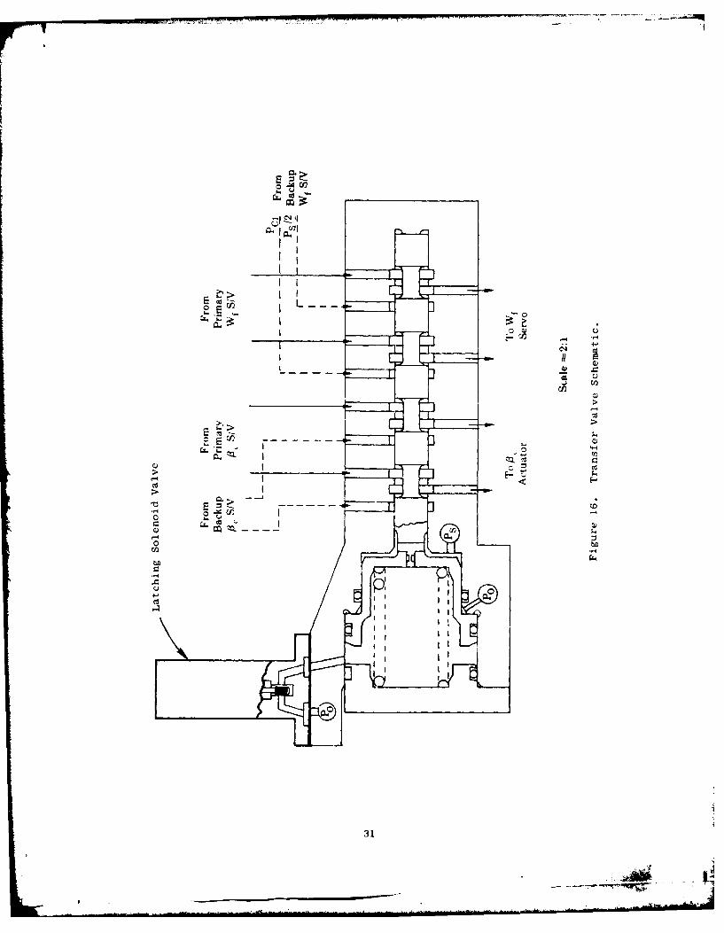
7. TRANSFER VALVE
The transfer valve (Figure 16) is shown in the primary mode position.
The solenoid valve is blocking the orifice flow back to the control case
(P,) so the pressure in the spring chamber is servo supply pressure (P,).Since the larger pisiont ar(a is at P . and the spring force is to the right,the net force is to the right. The. sl,]enoid valve (Figure 17) is of the
magnetic latching type. 'hen the solenoid valve is opened, the transfervalve spool strokes to the left stop (backup mode). In this position,
the transfer valve allows only backup Wf and 13c servo flows to the meteringvalve piston and core stator actuators.
The spool and sleeve are of (PJ stainless steel (MS 5630). Theseparts are heat treated at 1850 F to 1900 ° F for 50 to 70 minutes in a
neutral atmosphere and then quenched. After quenching, the parts are
stabilized at -1100 F to -120" F for three hours minimum, tempered at 6500 Fto 7000 F for one hour, stabilized at -110' F to -120' F for three hours
minimum, and finally tempered at 6500 F to 7000 F for one hour minimum.
The expected hardness is Rockwe2ll 15N 87 rinimum. The spool and sleeve
are :aatched with a diametIral clearance of 0.0003 to 0.0006 inch.
The backup control transfer sequence involves two switches which are
normally open and are closed when the transfer valve spool is at or nearthe backup position. The switches arid actuation means are shown in Figure
18. The switches are made by Tcx,< Instruments, Inc. (Part Number
MS 24456-3 or Vendor Part Number KX5-1-1). This type of switch is used
on the F404 engine .
8. OVERSPEED SWITCH AND VALVE
As discussed in a previous .ectlion, a si t.ch is used to initiatetransfer to the backup mode when NC; overspee:d is; detected by the hydro-
30
Mir
0.
0 ID
r. .
-4
31
-'4sw

CC
+
~r F
a
4., '.32

/C/>
E7 4 4
A4 4
33
mechanical backup control peLd sensor. The switch and the actuation
means are shown in Fi V ne 19. Tie switch (Texas, Instrument:; Part Number
MS 24456-3) is the same as thoe used on the transfer valve. Upon closing,the switch conducts 28-vwlt aircraft power to the backup solenoid. (See
Figure 15.)
The speed s;ensor pistn positLion is proportional to the square of
core RPM (N(;,2). When overspeed is encountered, the piston moves the valve
spool and spring seat to the left, camming the switch closed.
Referring to Figures 2 anid 19, the spool valve modulates the throttlingvalve opening pressure (Pv). This action provides N(, limiting at a levelhigher than that required to close the overspeed switch. A possible fail-
ure mode which makes this additional protection desirable is a stuck-open
metering valve.
Both the overspeed switch and the overspeed valve are adjustable.The switch can be moved on its; mounts; and the sleeve for the valve can
be shimmed. The nominal RPM settings and range are:
Switch 1042 + 5%
Valve 107% + 3%, -7%
9. DRIVE AND MOUNTING ADAPTER
The drive and mounting adabter are shown by Figures 20 through 22.This adapter mounts the fuel valve, the backup control computer, and the
transfer valve. The drive end of the adapter is designed to mount tothe JTDE gearbox.
The drive shaft (Figure 20) input is 6690 rpm at 100% rated JTDE core
speed (NG,). The drive gear at the computer interface has 45 teeth of 32
diametral pitch. The gear in the computer has 74 teeth so the speed sensor
input is 4015 rpm. There is an idler gear between the two gears.
A carbon face seal (Sealol Part Number B-56910) rubbing on 440C
stainless steel is used to seal fuel from the drive spline area. This
seal is used on an aircraft boost pump at approximately the same RPM.The spline at the engine gearbox is oil lubricated and sealed by an
O-ring. An overboard drain is provided between the fuel and oil seals.
To allow for possible misalignment, a separate quill shaft is usedbetween the gearbox shaft and the backup control drive shaft. The bearings
on the drive shaft are Marlin-Rockwell Corporation Part Number 104 KS or
the equivalent. The outer races of the bearings are clamped by a lock nut.This clamping method is used in engine gearboxes. The second bearing inner
race floats to allow for thermal expansion. Fhe expansion was calculatedto be 0.016 inch for a temperature change of 3000 F. Bearing loads are
modest: 67 lb thrust from a maximum case pressure of 150 psi. The thrustrating for this bearing at 5000 rpm is 500 lb. The calculated radial load
is 6 lb.
The drive shaft and quill shaft are of Nitrallov T M . The gear and
34
. I

0 0
m 4
0U
C
6--4
35

00
"41
0
4j
U
C) Cd
-4 I
ell
CDD
-41
36

Transfer ValveMounting Surface
(Backside)
Computer
Mounting Surface
Transfer ValveMount ing Surface(Backside)
Fuel ValveMounting Suirface -
Figure 21. Sketch Showing Drive and Mounting Adapter.
37

P S3 Bellows
Rel1i ef
Figure 22. P S3Pressure Divider.
38
K-.

spline are case hardened (nitrided). The housing is of aluminum alloy AMS
4117 (6061-T6).
Figure 21 shows the adapter. The mounting surfaces for the fuel
valve and computer are indicated. The mounting surface for the transfer
valve is on the back side of the indicated pad.
10. PRESSURE DIVIDER
The PS3 bellows in J85-21 MFC has a 200 psia rated pressure capability.
A device consisting of two orifices in series was designed (Figure 22).
Air from the compressor enters at the left and flows through a screened
fixed-area orifice. Air leaves the device through an adjustable bleed
which allows calibration. The fitting at the right connects the device
to the PS3 transducer in the computer. A relief valve is provided to
protect the bellows in case an overpressure is encountered during test.
Both the screened orifice and the relief valve are made bv The Lee Company.
The pressure divider is adjustable so that the pressure level at the PS3
bellows is 200 psia or less.
A computer pro>gram was defined which predicted Wf/Ps3 acceleration
schedules using the PS3 pressure divider and the recalibrated T2.5 sensor.
Figure 23 shows the predicted schedules for variour levels of T2. 5 with an
existing J85-21 MFC cam (Cam 2108).
11. OFF-ENGINE UNIT
The backup control off-engine unit is shown schematically by Figure 24.
This unit simulates the expected pilot's switches normally located in the
cockpit. It also contains a relay which allows demonstrating a failure
of the primary control. The role this unit plays in regard to backup
control transfer logic is discussed in Section 11-6.
Centralab makes the four-position switch (Type PA-2043). Struthers
Dunn, Incorporated makes the relay (Part Number FCM-410-109).
12. TEST CONSOLE
A test console was designed to substitute for the primary control
during bench testing. Figure 25 is the test console block diagram. This
unit operated the primary 1f and 8c servo loops. The operator can demand
a steady-state NG or an NG ramp just before transfer is initiated. The
test console metering valve circuit schematic is shown by Figure 26; the
stator circuit schematic, by Figure 27.
13. PRODUCTION HARDWARE DESIGN
The production design of the backup control would have several signi-
ficant differences. Among these would be:
. The fuel valve, hydromechanical computer, drive, T2.5 sensor,
and overspeed valve would all be integrated and housed in one or
more machined aluminum castings.
39

2-
o) C,
C,Ic U)
(14)
c s d/ i
40)

sl 0- HOLD
P2-12 P
Figure~ ~ ~ ~ ~~~] 243ceai fteBcupCnrlOfEgn nt
41SWTC
5T

The transfer valve assembly would be mounted directly to the housingfor the above components and there Would be few, if anv, externallines. The body would be of cast alumintum.
The overspeed switch would be mounted to the computer housing ina manner similar to that shown for this version of the backupcontrol..
" The off-engine unit would he replaced by equivalent parts in thecockpit and in the primary control.
The anticipated external appearance of the backup control would besLmilar to that of a conventional hydromechanical main fuel control witha transfer valve assembly mounted to one side.
The cost, weight, and size of the production version of the backup controlwere estimated during Phase I of this program. The results were:
Cost (1977 dollars) $11,800
Weight 20.2 lb
Size 2J9 in. 3
42
-.....

0
cc144
> 44 0 >0 410 >
ci r-4
U)U
., -4 0 ,0
40 U 4)
0 ) " 0 0
d
(UU
41 4 Ci
0i
43co4
0, 0 0
0 a) 1
U7U
4)4
4
43-

r 2II
I T aT-I
I !i -
I ' : Iz1
M44
F Q)
-I - --- - - - - - -
14 4 't-
ioi
444

*15V COM SK5
Figure 27. Tst Console trCrut
45,.
SECTION III
FABRICATION OF HARDWARE
1. HYDROMECtANICAL COMPUTER AND COMPRESSOR INLET TEMPERATURE SENSOR
The hydromechanical computer and compressor inlet temperature sensor
T2.5 for the backup control are the equivalent portion of the J85-GE21
Main Fuel Control. These components are production items at General
Electric's AEG, Lynn, Massachusetts, facility. The housings for both
assemblies are of cast aluminum.
Figure 28 shows the computer and sensor.
2. FUEL VALVE ASSEMBLY
The fuel valve was designed at the General Electric AEG, Evendale,
Ohio, facility. Most of the detail parts are the same as those used for
the fuel valve designed, fabricated, and tested for the Light Weight Fuel
Delivery System Program conducted by General Electric for the U.S. Navy.
The detail parts were manufactured by various independent machine
shops. The body was machined from 6061-T6 aluminum. The other parts are
prototype flight-type design. Figure 29 shows the fuel valve parts.
The fuel valve was assembled at the General Electric Company facility
in Evendale, Ohio.
3. TRANSFER VALVE ASSEMBLY
The transfer valve assembly was specifically designed for the backup
control. The detail drawings were prepared at General Electric's
Evendale, Ohio facility.
The detail parts were manufactured by outside machine shops. The
housing was machined from aluminum plate stock. The valve spool and
sleeve are of AMS 5630 stainless steel, heat treated to a minimum hardness
of Rockwell 15N-87.
The transfer valve assembly also involves some major purchased compo-
nents. These include:
• The fuel metering servovalve, which is of the jet-pipe fail-safe
type, was purchased from the Aerospace Division of the Abex
Corporation (Vendor Part Number 72144).
* The Sc servovalve, also of the jet-pipe fail-safe type, was
purchased from Aerospace Division, Abex Corporation (Vendor
Part Number 72137).
" The latching solenoid valve, which is a shear type, was purchased
from the Valcor Engineering Corporation (GE Part Number 4013145-337).
46
6w-___ I

U':
47)
7_47-

S4 --,
~48

The overall transfer valve assembly is shown (photographed) in Figure30.
4. DRIVE ADAPTER, MECHANICAL POSITION FEEDBACK, AND OVERSPEED ASSEMBLIES
The drive adapter, mechanical position feedback and overspeed assem-blies were designed specifically for the backup control. The detaildrawings were prepared at the General Electric Company, Lynn, Massachusetts,facility.
The detail parts were manufactured by outside machine shops. Allhousings were machined from aluminum bar or plate. The parts were assembledinternally at General Electric's Lynn, Massachusetts, facility. Where
rework was necessary, this was also done at the Lynn facility.
Figure 31 shows the drive adapter, mechanical position feedbackmechanism and overspeed switch detail parts. Figure 32 shows the hydro-mechanical portion of the backup control.
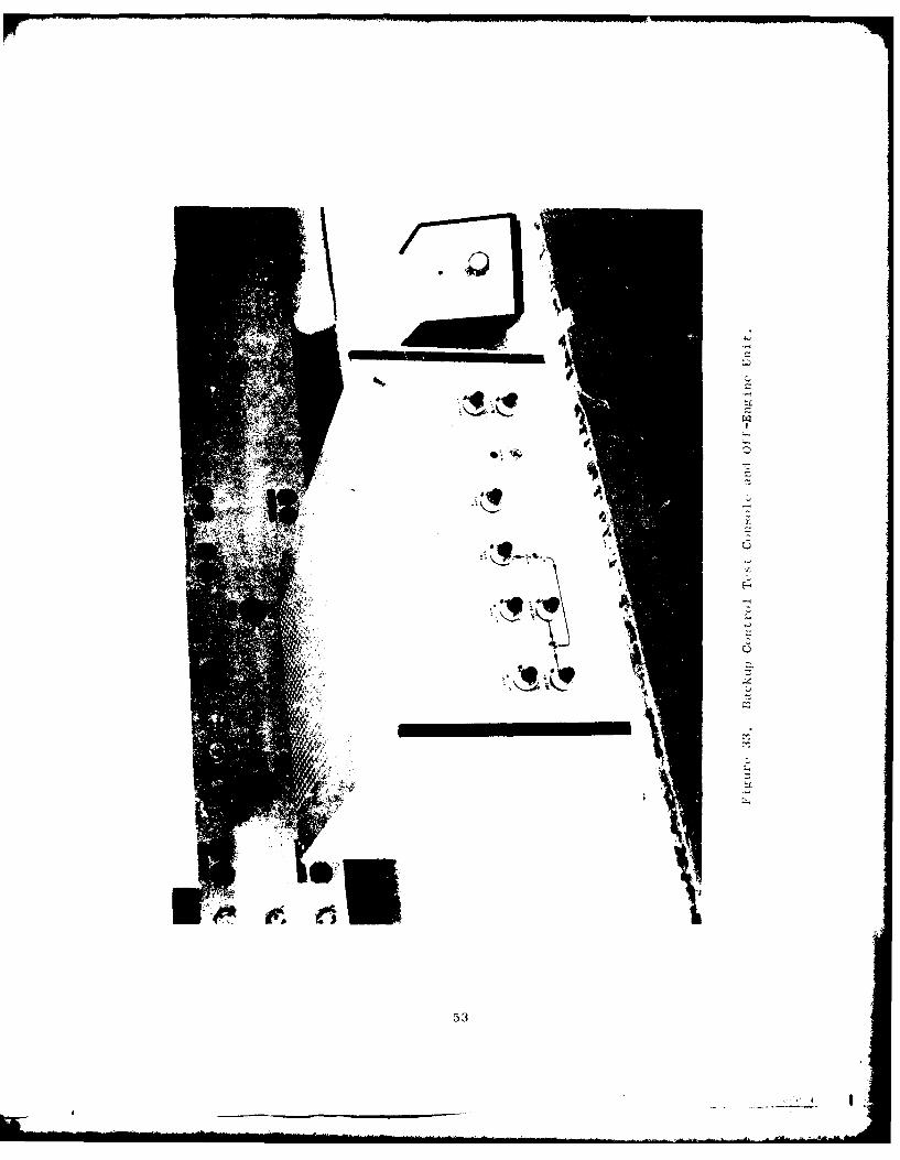
5. OFF-ENGINE UNIT AND BACKUP CONTROL TEST CONSOLE
The off-engine unit and the test conscle are electrical assembliesthat were designed within the Advanced Controls and Accessories ElectricalEngineering Unit of General Electric's AEG located at Evendale, Ohio.The piece parts were purchased. Assembly was done by the same people whodesigned the two units.
Figure 33 shows the resulting hardware.
49
__r-

ci;
C)
a LI;
-, U ' -J
F-.4
*1 C)
Cr
)
I
£...
5FF
I

U)
C)
*C)9 4~4
C)~igt A
C,C)
U)e -C)
'I sill l~
U)
C)QC)
~0
C)C)
0-4'-4
0* -4
U)
*I.e -1
- ---.--.-.---. CCC)
C)* 44 .0
C)C C)
-4
C')
* C)U*
CL
5~1
a
I -~

4 '
Figure 32, Hydronechanical Portion of the Backup Control.
52
- -- -- -- -
53

SECTION IV
TEST PLANNING
1. ACCELERATION SCHEDULE
The GE23/JIA3 engine acceleration schedule was selected as the goal
for calibrating the backup control. The plan was to use the J85-21 Main
Fuel Control 3-D cam (2108) and make modifications so that the GE23/J1A3
acceleration schedule at the nominal T2 and P T test condition (T2.5 =2.5 .T22.2240 F and PT2 = 20 psia) could be approximated.
The modifications to the computer and T2. 5 sensor were:
" A pressure divider (see Paragraph 11-10) was added between theP S source and the control, reducing the pressure at the bellows
to 63% of the actual PS 3.
" The T2. 5 sensor (see Paragraph 11-3) was recalibrated so that itsrange was 20 F to 3600 F instead of the J85 range of -650 F to
2750 F.
" A bias force equivalent to -5.0 psia PS3 was applied by means of
an available adjustment.
The predicted analytical results are shown in Figure 34. The GE23/
JIA3 acceleration schedule was for the digital electronic engine control.
The two schedules are quite similar. The approximation was considered
very satisfactory for the planned bench tests of the backup control.
These data were used to determine the acceleration schedule limits for
the calibration log sheets.
2. ENGINE MODEL
The GE23/JIA3 engine model was selected for the closed-loop testing
of the backup control. The model is shown by Figures 35 through 37.
This core engine is very similar to the core engine for the JTDE. The
rated engine rotational speed at the control drive pad i 6739 rpm versus
6690 rpm for the JTDE - a close match.
3. EXPECTED TRANSIENT RESPONSE
Fuel flow response in both transfer and backup operation is dictated
by the characteristics of the metering valve servo system, which includes
the nutcracker and metering valve piston. Referencing Figure 38, the basic
equations describing this portion of the control are derived as follows:
54
I.

(A t 15 2400 F .nd P =20 Dsia)
30
TIe Fla d
100 ,0 '1,80 5,00010,000)
N , rm
'7igure 34. Comnarison of Accel Schedules.
55

Pr ivtCotnt rto I
N GN
CC
See 5t i tSree3
Iigurtur 36( 7
1007 Ne C 6,739 rpm
Figu gtl ' 31 ''/ 1 ' Fr io M d l
56+

300
I (14,586, 217)Q I VS.~I) H S3 N-i 200
_ __,(13,130 127)S 100 - __ __ __ _ __
(0, 15)
0 (9000, 1")
10
0 2 4 6 8 10 12 14 16
10 1 (1 4,586, 8072)
W, vs. NG- 8 VS ..
8
60
4
0
z: (13,130, 27
(11,670, 1267)
0 1 !(10,200, 1912)
0 2 4 6 8 10 12 14 16
NG, Core Rotor Speed, 1000 rpm
Figure 36. CE23/JIA3 Loop Closure Functions.
57

(14,586, 0.0072)
0
0.8 ~(10,20 0, 0.70)l
0.61
~. 0.4
0.2 _ _
0 2 4 6 8 10 12 14 16
NG' Core Rotor Speed, 1000 rpm
Figui e 37. GE23/,JIA3 T-wp Climure Partial s.
58

%v1 0. h n
ar
o.A 1)

The input, "a," is linear with W /P demand. Therefore,
a = K 0(Wf/Ps3) (1)
where "a" is positive in the direction that opens the flapper.
From a moment balance on the error bar, we get:
F(a) + R4 LL4 1.125 (h-hoJ R24 24 + 0.5 (h-h) +
(Y-Yo (0.5) (2)
From a force balance on the power piston, we get:
2R4 5 (L4 5 + x) + (0.785) D1 (Px - P) = (0.785)
(D22 D1 2 ) (Py - Px) (3)
A pressure balance from rod-to-case gives:
(Py - P) = (Py - Px) + (Px - Po) (4)
From a flow balance on the head end of the power piston, we get:
146(0.785). D2
(- . (P P)+(0( - 2Po
146 (' (p P ) (5)
From a flow balance on the rod end of the piston, we get:
P )(D 2 2 7720 - PP ) = (0.785) - )x + (P - P)
(in LOHM form) (6)
A LOHM is a unit of resistance to fluid flow where 1000 LOHMS willflow 50 pph of water at 25 psid.
More pressure balances give:
(P - Po) = (Ps - P ) + (P - P ) (Ps - P = Constant) (7)
S 0 S y y 0 5 0(P -P)= (P -Px)+(P -Po) (8)
60

The feedback spring cam motion gives:
y = 1.152 x (9)
In the above nine equations, there are ten variables, all of which,except for the input (Wf/Ps3 ), appear at least twice. It is thereforepossible to find x as a function of Wf/Ps3.
Linearizing, transforming, and combining the above equations gives:
Aa = K A(Wf/PS 3 ) (10)
1 0.5
F Aa - R4 (-l-l) Ah = R24 (0. 5 ) Ah(O.5)+R2 4 (0.5) Ay (11)
R4 5 Ax +(0.785)D 2 (P x-P ) (0.785)(D 22-D1
2 )[A(P y-P )-
A (Px-Po] (12)
-146C,(0.785)D 2 2 ix=-4C ( 5 - A(Px-Po ) + (0.785)D2 S AX2.,/P (P s-P x) 0
oP ) +r4hA(i) + X/\AT 0) Ah (13)
-77 2_ 2A(P-P) = 0.785(D2 -D1 )SAx +
77 A(P-P) (14)2(250 V p y_ ) 0 Y0
Ay = 2(1.152) x0 Ax (15)
Figure 39 shows the above equations in block diagram form.
Figure 40 is a repeat of Figure 39 using the following constants
and steady-state conditions for 13,500 pph flow and P -P = 1050 psi:6 0
61

-77 7"
C
K U
Hc
Ch
62--

.LP
AJ
0 U
cc o
C;C
C;C
444
63C

lb/4 .) 1 .2 5 i.
0.1/ n --P =~ 551 psi
V o
1)N 0. 21 i).'1)4 M P" i
D = 0.752 Pn - = 6004 pil
R) = 1 045 ibn. = 0P 4 0 ps
DL = 0. 5 inl.
The metering valve is contoured to give:
Thus, Wf 83,000 X0 Ax
tieAssuming~ that thhotlnaveefcitouesa00 second
0.05 51 880 f
The speed servo loop was neglected since its tine constant is less
were as nelce.A esiaeo tegoenrfeu cyresponse wasobtanedby reaingtheconrol s asecnd-rde sytemcomposed of two
W f/P S3 rto e ptecluae oenrfeunyresponse, with
4. EXPECTEDTRANSFERCHARACTERISTICS
An estimate of the fuel flow, response following a transfer, assuminga large difference in primary and backup demands existed, was made pre-viously and reported in AFAPL-TR-77-92 (Reference 1). The resulting W ftransient (Figure 42) showed no tendency to overshoot, even with arelatively large W f difference (2540 pph, or about 17 percent) between
64

Phase, degrees
0
Cl)
0'
- Cl)
;L4
gp N7/ 0
65C

E
o- a
o ~ C
C- d
C0
F-.
-14
E~ -2C -HtLU.
CI
.ZnoH lad spuflod -ol Mlanq'
66

the two controls.
The previous study made the simplifying assumption that the pressureon the rod side (see Figure 38) of the metering valve power piston wasa constant 69 percent of the supply pressure. This resulted in an effectivetime constant for the metering valve of 0.0043 second. Referencing theschematic of Figure 38, and applying equations 3 through 8 of the basicsystem description of Section IV-3, it was shown that the slew velocityof the metering valve is limited by the sizes of the orifices on the rodside of the power piston. For a 0.036 inch diameter orifice on the returnside, a 0.033 inch diameter orifice on the supply side, and a Ps-P =
1050 psi, the slew velocity in the open-flapper direction is 0.34 0
inch per second. When the effect of the two orifices is considered inthe transient analysis, as was done in Section IV-3, the effective timeconstant of the metering valve is found to be 0.062 second. The resultingchange in the expected response following a transfer was small - about
0.15 second longer than the response previously calculated.
67
___ __ __ __ __ __ __ __ I

A prctiiiinor 1iitr v 1 otrl~a c. rrdicted atthle dCeleral Llcrir ,,iv' t I'van, M alret.Becaus,-ettice 185- -1l rm in ti, riol I ''r i.-: rO tr re, ites'tl -tand u-a.savailc'1 for Coi r rTr'1L 1!. dt u lo iri for scutl inp th~e PLA 'i1sx
and Mil stops , L ic O'v' llspl~c : i md II Ui c Iyd rorrcchin i Ai o v;e rspeed1limit L . Th r o LiIrinm, Ii1 c l~ iL , orc rn~L Id I J 1) L rd i x Bi
lbi in ; ;,11 I il'tcirw ro simulatorprs u e Iihe I IcN q ttory ,r r' o till point bei; sliglitly
out ot Liw i t
Irlc T I ,nSi 11"' j : i '. Ii~ I k~ i b r te doIVV thk2 rtiL i.,i 1t or U, rFO o Ci 00 io id eoo, areshown bNv ''Ml Iwhor ]ht "t',i I I~-' j, 1: :i t1 1iC I T: r e ' zenc e
to tr ii attolie sensorwi- t~ I I .,I im i iiYr sv k hift
(about. 0. 0' O i iih) ii L i I, i.l q i :Li ' A Li arc, co-mparedt o t i I o S r '' " "Iki !i _c :t t~ r ',ited to the
A prl ~1tL.V ChedluleS
sioil 1 'o~-. ' ''LI ,a- c:,o~rdthroughthe foel li, il --e' u' oio-r 1,,w wre Obtained
bv trea~ in.i1 ol'servo p rcssure
occur red. V!t io ' i; 1~l( , t" is) DV osi:ng the
equii t ion
where x H:- 1tc L ri'' W'i 'rc iiw cconstant L6,O00 isbased! orr tli t r ii po' I 'in 1 Tw tr i t l ci o 53 psid . The
minimum 1 1()%, ' op v-s -s'! to "I porL oj,. (if a x =0.0767 inch,which conrrxu t- , ? )0 pli fli. iii', o! w' 0 '- isd as the refer-ence Fo)r tin. ktin. a k .n Vlvo po0I jt 011 1 1 r-dTh esolting acceler-ation ;cliwdu2 d~i~ iridicciteS or 1 minor ii ''rati r [ho decelerationschedulc kso i~ I ; 1~ vi
Trh (' I t I' jii 1 1- 'L :W I 1o i 1 ryldr"" C11ui CalI overspeedl imitL wo-re t-,L i tui li Mit U- n' )L Ill Md' or! L pS were also setw ith in Ii I",i t . II llo b Lik 1,, on L1-)' wo,5 tht'1r ,h i pi'- i tO the GeneralElect r ic Comlyin I Lt i tv atr Evcnd(rJ' Oh

TABLE 1.
TEMPERATURE SENSOR CALIBRATION
Desired Measured
Temperature Reference ReferenceTe 0rFrDimension, Dimension,2.5 - In. "El - In.
20 1.6004 1.6072
40 1.5849 1.5903
60 1.5696 1.5752
80 1.5546 1.5564
100 1.5398 1.5410
120 1.5253 1.5262
140 1.5110 1.5110
160 1.4970 1.4955
180 1.4832 1.482
200 1.4696 1.4685
220 1.4563
240 1.4431
260 1.4302
280 1.4175
300 1.4050
69
o • ..

The test : erup us -ed for the above testing at AEC Lynn is shownby Figures 43 aind 44. Looking at Figure !43, the dial indi. ator at theupper l.-f t-hauId corner was used to measure feedback cable travel (C).The dial indicator at the right center was used to measure the meteringvalve po.it ion. A P actuator is shown below the calibration fixture.Figure 44 shows the other side of the backup controoi. The power levershaft and thj shutolf valve shaft are shown pointed toward the upper edgeof this picture.
2. CALIBIRA[ION
The remainder of the backup control calibration was conducted atEvendale, Ohio. The results are included in Appendix B. The data takenat Lynn, Massachusetts, for the throttle stop adjustments, the core statorschedule (N), the electrical overspeed signal, and the hydromechanicaloverspeed lhmit are also included.
The acceleration schedule limits used for the calibration log sheetswere calculated based on an existing J85 main fuel control cam (2108).However, the most readily available hardware was selected to build thebackup control. In this particular control this resulted in using a camthat is different (2103). Figure 45 shows a comparison of the two camsat T = 2240 F. At that time, the cam difference was ccnsiclered tobe t45 reason t:he first, thirteenth, and fourteenth points on the accel-eration schedule were slightly out of limits. The acceleration schedulecalibration required a high metering valve pressure drop. This was con-sidered to be the cause for the "rich" deceleration schedule. The decelschedule is a fixed W /P ratio and not a function of the 3-D cam. Theresulting acceleration an deceleration schedules, however, allowed
sufficient margins between themselves and the engine steady-state oneratingline. This was necessary for the subsequent transient response testing.
Early in the subsequent transient testing, when the loop was closed
on the stators (P C), it was found that the stators did not respond to
T2 5 changes. Investigation revealed that the temperature sensor had
not been properly installed - that is, the feedback link did not engagethe servo piston (see Figure 8). This caused the sensor to remain at a
low T2 . position - about 200 F. The effect this was presumed to have
had on' he acceleration cam is shown in Figure 45. The wide difference
in the expected schedules for 2108 (T 2240 F) and 2103 (T , = 200 F)
further explains why the acceleration -chedule did not calibra e as
expected and why the required metering vclve pressure drop was 63 psid
instead of the expected 53 psid.
The backup control was shipped from the AEG Lynn facility, where
the T 2. sensor had been removed to reduce the risk of shipping damage
to the capillary tube. The sensor was reinstalled at the AEG Evendale
facility, and this is when the feedback link failed to get ergaged
with the servo piston. Once the sensor was roinstalled in the normal.
manner, the stators responded to T2. 5 changes.
70

PI,
I';L'U ,p

72

32
2103 Cam(T2 .5 = 2240 F)
28 /-1218 CamT 2 5 = 2240 F).5~
24 2103 Cam
(- - 200 F)
204000 5000 6000 8000
Control, rpm
Figure 45. Comparison of Cam Schedules.
73

The shutof-f valve leakage was out of limiLaj. The leakage indicatesthat the mating parts require addittunal lapping,,, which will be done beforethe control is used on any engine test.
The test setup used for calibration and subsequent transient response
testing is shown by the three photographs that constitute Figures 46, 47,and 48. Figure 46 shows the backup control on the test stand at the leftand the FIOl augmentor fuel pump on the test stand at the right. Figure47 is a view of the backup control showing the hydremechanical computer.In contrast with the machined bodies for the other subassemblies, thecomputer is enclosed in a cast housing. The enclosure wrapped in white
insulating material is the test fixture for the 1) 5 sensor. Figure 48shows the F101 augmentor fuel pump. This type ofpuflmp is intended for
the JTDE testing. An Fi01 augmentor fuel filter, mounted to the pump in-let, is also shown. This pump and filter were used as the fuel pressure
source for all the testing.
3. BACKUP CONTROL TRANSIENT RESPONSE
When operating in the backup mode, hydromechanical components pro-
vide the normal engine control functions:
" rpm governing as a function of power lever position
" Scheduling of main fuel flow as a function of N P and T2' S3 2.5
on accelerations, and as a function of PS3 on decelerations
" Scheduling of 6 as a function of N 2 and T2
Steady-state and transient response characteristics, when in the backupmode, were of interest because of the adaptation of the larger flow me-
tering valve to the J-85 computer mechanization. Testing to determine
the performance of the backup control consisted of the following:
* Defining fuel flow (W-) and variable stator vane (N ) oscilla-I C
tions on accelerations and decelerations.
e Defining governor droop characteristics.
* Determining frequency responses of fuel flow and stators to N 2 and
of fuel flow to PS 3 " 2
Figure 49 shows the bench setup used for testing the backup control. Both
open-loop and closed-loop testing were employed. Open-loop fuel flow and
stator oscillations, obtained by operating the control at fixed values ofN2 , PS3' T2 PLA, and control inlet fuel pressure, showed random driftsOf +20 pouAns per hour (fuean flow) ad ± 0.001 inch (stator). Head regu-lator oscillations were typically ± 0.2 psi. Figure 50 is a typical
steady-state trace.
74

I)E l4
43.
78''i

1, 17 V I Il l'I', I it it I, -I I- c I ck 3 ( )ItI C ~t I,I.

WI
C7

ccc
41~ 4J
4W (1)
00
78N

14;
.44
i l
I ... . . . . . . .
Cd
.-.. . .; . . . . . . . .4 -
. . . . . . - • . . . . .
.1P
'4-4
c 0
K................. ..... .... 1
ON amwim 00.1
79
. .... | _ __ _ __ _ _ _I

FigurS 51 31nd 52 show fuel flow, var ib It s tator p .e.ition , and head, cillations on a spet:d ranp conditio: of , £00 rpm per second, with PS3'
T , ILA, and c(,Ttrol inlet fuel pressure fixed. Fuel flow can be seent' , sttle, with little oscillation on the acceleration mnd deceleration
.,J Iittlt overshoot daring governor cut-in, when the governor takes overtie control ot fuel flow.
Figures 53 and 54 ,Jhow typical rhrottle bursts and chops, operatingclosed-loop and using the dynamics of the (;1"W engine in the cjosed-loopsimulation. The concrol can be seen to ride che, acceleration or decelera-tion until the governor modulates Wf to hold N2 at the demanded power set-t ing.
Figures 55, 56, and 57 show typical open-loop governor characteristicswhich define the governor droop and hysteresis. The droop characteristicsare seen to vary with N, level, yielding higher gain at higher power set-tings. Thu dispiayed 0.053 W /P ratios per rpm at the high speed points
f S3were expected with the J-35 computer. Speed hysteresis, which increasedinversely withi power setting, is observed to be constant at a given power
setting regardless of speed swings.
In the J-85 main fuel control, the W feedback spring is attachedfdirectly to the metering, valve. To allow using a larger metering valvewith a triangular port for the backup control, a rack and pinion, a cam
and a bell crank were added between the metering valve and the feedbackspring. This resulted in more friction, which increases hysteresis andreduces repeatability. Although the increased hvsteresis is still accept-
able for this backup control, the production version of the backup controlwould be mechanized similarly to the J-85 main fue! control. Its hystere-sis would be less, comparable to that of the J-85 Tnair fuel control.
Frequency response testing on the governor (AWf/gN2) and the stators
(Ac /AN ), typical traces of which are shown in Figure 58, produced magni-
tude and phase characteristics shown in Figures 59 and 60. Flow responseto P (AP/AN2 ) was almost identical to flow response to N2, since bothspee and $3 work through the nutcracker/flapper and fuel valve power
piston system.
Fuel flow response was lower than anticipated, primarily because of
governor hysteresis. As seen in Figure 59, correcting the calculated re-sponse of Figure 41 for magnitude and phase effect of 50 rpm hysteresis
gives relatively close correlation to the test data.
4. TRANSFER TO BACKUP MODE
When operating in thE primary mode, the transfer valve blocks the
backup Wf and Pf servovalve outputs so that interference between the twocontrols iq prevented. During this mode of operation the backup control
so

C)
C )
cl
C 4
0
ON (133
81)

a0
C1Lo
ON -4
820
.AP-A094 730 GENERAL ELECTRIC COI CINCINNATI OH AIRCRAFT ENGINE GROUP F/6 21/SBACKUP CONTROL FOR A VARIABLE CYCLE ENGINE. CU)
UNJL G0 H S KAST F33615-76C-2086
UNCLASSIFIED RGOAES50 AFAPLTR792069 "
EENOEEEONEE-mhhhhhuwM~~m

V, -L. _ _ _0 0-
cn u
r- 0 -l
ol qd JA
* >Ci83

. . . . .
... .. ........ ....
. .. . . . .
.- . I. ... .
. . ., .... . .. )
E C3
x~ -d J ....
84,.,-

rz . . . . . . .
.. J C 4------ --- c-
i4i
CYC-
d d
II, 85

III
CCA
kidd
86K

o r-o
44c C-t*
(n 0 4 r
<c-*z
IIr
W -... ..- .. ..... - *
. . .. . . .
orr
I/ ld
I. I-7

Nc r rpin .
t
BRUSH ACCUCHAPT
- --- --- .4 - ,
4 4
-. -. --- --
J\.~ ~ . . . .r\ .r . .t,, I~ /qe - Repne 0H
Fi_,r 58 yia r'IcyRsos rcs
*1'*'88

0
/1~
/ // I
( I
I, /I /V /1
UI --- ~I - -------- -
I C)
I C)
I[IIl -
II -
C)
I I I U
I I,I U
0*~
C)
2 -0' A bL
I I
I I0 - 0 0 2
89

dugres C
LI~000.
C)
0*w
0
C --4 - -______ .0- z ~
-40S..
0CU0.0
-4 0
CC C
- Cr CD
S..
Cr
C C CCO
) A~IP NJ *~i
90
U
,-..

is continuously tracking the engine. Because there are schedule differ-
ences between the two controls, backup control errors can exist which
..Id position the hydraulic error amplifier (or servovalve) to a sntu-
r;itAl cnc!ition at the instant of transfer. Thus transfer transients
fIllowing a switch from primary operation were of primary concern. Test-
ing to determine the transient performance of the backup control consisted
of:
" Defining the responses obtained following a transfer to backup
from various steady-state and transient conditions
" Defining transfer characteristics upon automatic switching to back-up mode by the overspeed switch
" Defining governor action upon modulation of the throttling valve bythe valve driven by the hydromechanical speed sensor upon extremeov-,rspeed.
Transient behavior following transfer from the primary mode to the
backup mode, was obtained by establishing an error between the two controls
whilc operating closed-loop. Both small and large errors were intention-
ally set. Transfers at both steady-state and ramp conditions were made.
Typical transient behavior following transfer at steady-state conditions is
shown in Figures 61 through 64. As seen on the traces, small errors be-
tween the two mode- produced only slight momentary transients. Fuel flow
peaked approximately 200 pounds per hour rich but recovered to the backup-
demanded flow within 0.6 second. Stator transients showed a similar result.
With intentional large errors existing at the instant of transfer, fuel
flow merely went to the acceleration or deceleration schedule, causing the
simulated engine to accelerate or decelerate normally until fuel flow was
modulated to hold speed at the condition demanded by the backup control
power lever setting. Stators followed speed with a slight overshoot and
undershoot before stabilizing at their new requested position.
Automatic transfers to backup upon overspeed conditions were identical
transients to those shown in Figure 64. The system transferred at the
proper preset overspeed, and fuel flow responded to the level called for
by the power lever.
Figure 65 shows the action of the hydromechanical governor, which
acts to close the throttling valve to reduce flow in an extreme overspeed.
Fuel flow was cut back at the proper overspeed condition. With the test
bench operating closed loop, speed decreased when flow dropped, opening the
throttling valve. Speed then increased until the overspeed point was
reached and flow reduced. A limit cycle with a period of approximately
3.1 seconds was established, with control speed varying between 7000 and
7500 rpm.
91

-44
* 0
c0
CD
a4
0r
92

* fl-u
- -----------.-.--- ~-.
Cfl
_ CC
o )
.C)
r.
C.)
CC
a
-- .
93

M
F-
C-)
Ct)
_______"Iowa"l

rU)
t)
>1 0
U-4
bt
95)

C'-- -- ---- 1 7cc4-
4 M- 4.-r, ~ ~~~ Q
W 4
CD±
* I 96

5. CY LI( ENDURANCE
The planned endurance test consisted of the following steps:
1. Check calibration
2. Run 40 hours of accel/decel cycles
3. Conduct 100 transfers to the backup mode by going overspeed
4. Conduct 10 overspeed transients during which the hydromechanicaloverspeed valve modulates the throttling valve
5. Recheck calibration
Step 2 of this test required operating closed-loop in the backup mode. Thepower lever was cycled from idle (70% rpm) to max (100% rpm) and the enginemodel plus the test setup caused the drive speed, fuel flow, and PS3 tocycle. Temperature (T2.5) cycling was not planned.
The calibration check disclosed that accel schedule repeatability wasnot satisfactory. Experimentation indicated that applying current to theprimary Vf servovalve would change fuel flow a small amount. It was sus-pected that transfer valve leakage caused a null shift in the flapper servoin the hydromechanical computer. The transfer valve was needed only forStep 3 of the planned endurance test. This portion of the test was con-ducted first. Speed was ramped successfully 100 times in the primary modeto the point where the overspeed switch tripped and automatic transfer tothe backup mode occurred. The transfer valve was then removed.
The calibration check, with the transfer valve removed, indicated thatthe repeatability problem was still presenc. Temperature sensor performancewas then chocked and the performance was found to be very erratic. As dis-cussed previously, the sensor was installed improperly upon arriving at AEGEvendale. It was now suspected that it had been damaged during that installa-tion. A suspected cause for the observed action was that the jet pipe wasbent, keeping receiver pressures too low to properly control the sensorservo piston.
The temperature sensor servo pistion was shimmed to the high temper-ature position. The accel schedule was run twice; the data are shown byTable 2. The repeatability was considered normal. (It should be notedthat, for the J85 main fuel control, the fuel flow feedback spring isattached directly to the metering valve. The backup control has a rackand pinion, a shaft, a cam, and a bell crank between the metering valveand the feedback spring. It is expected that a J85 control would haveeven better repeatability.) The remainder of the endurance testing was
97

TABLE 2.
ACCEL SCHEDULE DATA TAKEN BEFOREAND AFTER THE ENDURANCE TEST
1 Before* Before* After
Data c S3' 3 Wf, Wf, Wf,Point rpm psia psia pph pph pph
1 6360 30.5 21.0 1404 1456 1396
2 6360 54 3L.7 2321 2348 2302
3 6360 67 42.7 2852 2892 2857
4 6360 90 57.1 3784 3827 3798
5 6360 104 65.9 4348 4387 4341
6 6360 114 72.2 4749 4778 4736
7 6360 144 91.2 5951 5990 5913
8 6360 176 111.3 7205 7249 7177
9 6360 222 140.8 8923 8981 8942
10 4770 54 34.7 1599 1602 1567
11 5175 67 42.7 2119 2131 2096
12 5565 90 57.2 3412 3445 3440
13 5710 104 66.0 4099 4112 3972
14 5840 114 72.3 4859 4831 4805
15 6120 144 91.2 5950 5971 5999
*Second set of calibration data to show repeatability.
98
. . . . . ... g,

then conducted. This included 1600 accel/decel cycles at 90 seconds per"ycle (about 40 hours). The accel data taken after the endurance testingis also shown by Table 2.
6. SUMR .\Y
The overall performance of the backup control during the test phasewas very satisfactory. A total of 173 bench test hours were accumulated.This testing is a big step in qualifying the backup control for on-engineuse.
The test results indicated that some changes should be made to thelatching solenoid valve and the transfer valve before the backup controlis used on-engine. The latching solenoid valve coils should be replacedwith ones capable of withstanding 28 volts continuous duty as originallyintended. The vendor overlooked a note on the drawing and used coilssufficient for momentary power only. The proper coils would be about1.5 inches in diameter versus the present 1.0 inch.
The transfer valve leakage affected the backup control W servo. Anull shift became evident when current was applied momentarily to the pri-mar. Wf servovalve. The transfer valve leakage should be reduced by add-ing seals to the spool.
Thu T ., sensor problem was attributed to damage caused by improperinstallati6fo. This is a proven component so no changes are recommended.The hysteresis in the speed loop, although higher than desired, is ex-pected to caiuse a random but acceptable "wander" during engine test. Theexpected wander amplitude will be about +55 engine rpm (or +0.35;) at
rated engine speed.
99

S ECT I ON V I
CONCLUS IONS
The concept of using gas generator speed demand combined with fuel
fl wv scheduling has provided a practical basis for the variable cycle engine
backup control development. Success has been achieved in adapting a
control built with hydromechanical technology to interface with a primarydigital electronic control, thus providing a backup that is free from
environmentally induced common failure modes.
Testing of the resulting backup control indicates that satisfactory
transient response has been achieved. This backup control h.3s demonstrated
thv required type of transfer action. It was shown that stall-free
transfer can be achieved by having the backup unit continuously compute
the controlled variables and thus track the engine operation, in readiness
for backup action. These developments have led to a practical and ef-
fective backup control.
Thi.s techrology places the variable cycle engine one step closer to
application reality - especially for the single-engine aircraft applica-
tion. Finally, this accomplishment makes it reasonable to begin the in-
troduction of full authority digital electronic controls at an earlier
stage of weapon system development than would have been practical other-
wise.
100
|I

SECTION VII
RECOMMENDATIONS
Based on the results achieved by building, testing and evaluatingthis Backup Control for a variable cycle engine, it is recommended thatthe activity be continued toward practical engine applications. Curtain
design improvements identified during testing could simplify and enhance
on-engine usage, and should therefore be incorporated next.
Using the hardware prepared here, the development should proceeddirectly to on-engine testing using the GE-JTDE, for which the controlwas designed. Such on-engine measurements should be directed toward
obtaining data correlation against a FADEC as the primary control operating
a variable cycle engine.
101
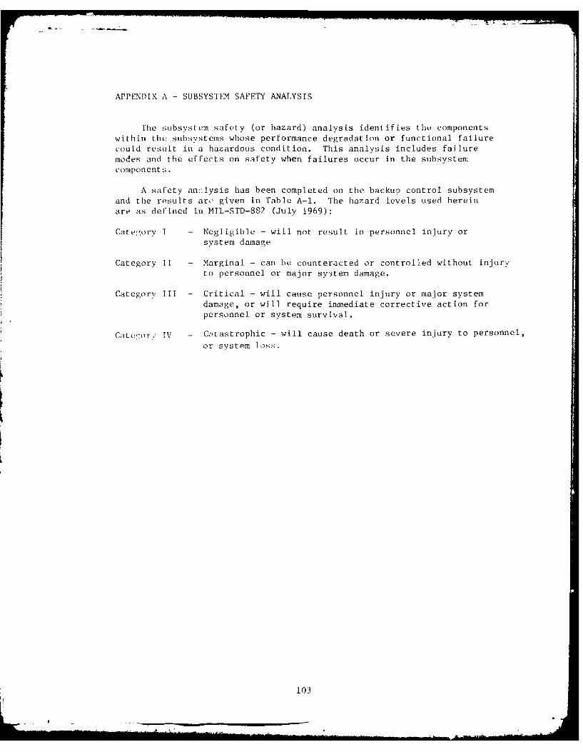
APPENDIX A - SUBSYSTIt SAFETY ANALYSIS
The subsystem safety (or hazard) analysis identifies the components
within the subsystems whose performance degradation or functional failure
could result in a hazardous condition. This analysis includes failure
modes and the effects on safety when failures occur in the subsystem
components.
A safety an ']ysis has been completed on the backup control subsystem
and the results are given in Table A-I. The hazard levels used herein
are as defined in MIL-STD-882 (July 1969):
Category I - Negligible - will not result in personnel injury or
system damage
Category 11 - Marginal - can be counteracted or controlled without injury
to personnel or major system damage.
Category III - Critical - will cause personnel injury or major systemdamage, or will require immediate corrective action for
personnel or system survival.
Category 'V - Catastrophic - will cause death or severe injury to personnel,
or system loss.
103

w0 0
0 ) 0 U
-4 4
N> r_ 0 '- 0
00
U) - a I
qn ca C D 0 a u ( 3) -C ,-A En
1-4 HU 44o :1 - a .4jt-Z4 0~ 10 UU M04 M .00 MI
0 ~~ "~ >-0-- 4.C -4 ") > O EV *-;3-H4 aj)'- 41W (A -4 w 0 0 U)- CU ~ U ; 0-a)
V) :n 0 a 0 a l. 0 .U 0- )-4
: r-0 (V)444-- E0 4-1 a~0V u~ U)o 1) 4.10 CL
( 0 -4 ~ 4 W, 0- 0040U)C M)> C W -> M 0 CI. (
Q) C: u r- 0V~4J ~ > 0 ' Ii -H . -' r4 >4.
0 m '4-' tn 0)4 ca 0 -H -14 CO 0. wV~. m4 CA
a)) 0 E, ) 0 0 r40m0- U a0- = > U)4.4. j- 0 00 w ) 0H z0 -'4 (U 0 -1 (nU u5 44. 4-."-q :I ca C-4 0 ) )
U) ~ C 0i uJ0 .0 MH )( U 4-0 00- *Hc r,-H XoV) 0 (V o)- C COrS a 'I) XJ.--C-C0 >( ~ 44- QU
0C- 11 (3) 3: MA -H -.--- 4 0 - 4 -S& > 0 04-4 0 a0 4 = U)4~1' ~ 40-U>4 A-0 4-.-(U) ) : aC')
-H U) C-A Am u W u 44-- W, w >-4m 0)0C1. z
u V C 1,) UC ) , C- .- CV: 0 )0> ca al - '- w
- U) CL> '0 A 0 J F 0. L', 4-) ' 0 -0 4- 0 > ) 0.
01: 7 0 )v- ( O0)-- )w4Aiw>) Uw A) 1--A0 ) U)0AwIn t4 1 0. CU)0 C 04-. -r400 "11 C >) M-. . z w U) C I.
0 l rC---4o-r 0.CO- 0W 0 ) - 4.0 UU )U > -- 0 ;a) u w.a
0 ~ ~ 04 0CO--' 73U)'40 A~ 4- n)-4- .0 A4cl C) 0'0 A 0'0 U 00 - ) u 05 r- -$-, - 04
&, C- 0)0 al)0C ' r_04' 0(I *U) = .0> D">4
(V -0 04 L.--C 0 '0- u (tO (AS ca C) . 0 a :
~C 00 AUV -. 0 0 0 0A 0040 A 04004
54. >44Z 0 )0 > 0 0- 0-
* ) -3~- -U'00 0 4-U0A440-4- 0'U'~~~ ~ ~~~~ ud 000 r)4J - .J) U' -0I'))
.0 0~- A
-10

(D 0 IC:
GJ 0- -- --1
r- C- a) 0D(U oc c c U
-00
C: 0 CQ) a U(
c >~ mN Cl -4V w 0X
.r iu U. 0 w m
(U a)(3 OW _ CO 0 w 4L
UU -Q)c 1)E . r.C 0 > co 4-( 5
CU (U) U-0 a)-. VC 00 0( >. (U ( C U UE-
E > CU C CIU Q() Cu CU aC EV 0 - _ U r - H Q) - U Q. CC- Q) ; U 4 CU
(C 0 TC OC > ~ , (A~ .>O~ .0 X- C0Q Uw H 11)EH 71 t 0 CCC &(C-UO wUCE OOU CU S- V E U 0)uQ
0t UC Z- - u a> j( C. *-- U J UU (mU C uU *CciH C *0 4( ~
0 fl.11 U a.0ci 0 TI 0)C -u m
' U.C . ~ ~C0 0C-.C- w J.C- ~UCz G) r- "CCJ- '-tU m- "UC r, "
O (U a, 0.U -- C ( 'a 0 .Ou 0 (co .r: lC-o V
C- "U4CC 0) ja,4 -0j (UE O U C U zn )H r
11 -i cC C CC 0 CL.- :>C:G riJU C. O '4 -40~ C .0 0 0 . u m -40",C. .,jE Z f.0C U -4
C)~~t mU 4C4( CC CUU) -4 H ( ~(C U( 0 -(-4 UO0 r w a EC CEEQC> M U4-4(
M~ (0> rC - c C>1 " cn CUi zC QC U ( -p
U 4 u-- UCO Ef-- Q) 40H C.((0 0 4Q) EO (I-)C - I- C4C 0- ,-. - U) CI z
< (C UU0u a Q) a-4 UU U OW ir~U O(I U C CA cn C. 4.- HE U) aC(0 CCIO Q.
a) 4 ~C '0 Un U.0 0)*CC4- (04 = CIn0 C Cl TZ a .Cl E44 CII'O U E0T (n4-HH 2V) C- uH
.0 0 . H - (0 (2 . ) O4 ~ C. CC H U >U C0cc (2 EDC C H E~ ~ ~ .C UE.(00 ... 0 .4
1 0 w
r. " mC0. 0 0H ) 0 (LI.1 O
w) C 0 ItUO W*c u- Q CCto CV .CU C:6 C1J UIO(C. Z
NC 4-' ro C w O .4 0)
ca a)104 :1 0- -4wk
0 -4 4J U U( >
- lc ( 0( u w 0 0 w 40 0a) (r, ) td CO -H UOQ)HU( a)
H 24W C(Ic ,4U- UWO.E CU.
a)4 rzU -4 UH 4JCO-.W> WCL
(U UDE( 0 -0 .C 4) -JO=u coC :3 M : rCl- uE 41 P O4-4CH.CEC U V) (
105

C: 0
Co w -4 r-- - '
u- =sCo._: .I mQ -4
-H0 a) coj H a - : ) 0 0a)CH )., mI-- ca CO 0 0 - 0 1.u 0 )
C: U C 0 ) ) F.0C a
.- CC0 '4 J 0 0 .m04~ CO MH ) =>a U wQ
w) CC 0) c L 0 C . <.jc o a
0d $ W =~ -) 0- Q) 0 P )>L(A 0 ) ". 0 u 4.4 ( 0 04 - 4 ) cu 0: CC z
ca " :-4z )0 n~ Q 0 0 CI 0 m -jwucmiC
a)C 4 00 0 'C E4 OCCa) 0 Z4 0 G)'4c"." .00 " "- 0. 0C C0'- -4:3o--- C O 0 ' - '-
> l u).- '4 C' P0 . I-= 0 '-~ a) CC ". jD 0: U 0-u 09
-H 'a) CC '.. 0 -'- 04".- 4-,-' CC4),- m 0 QC.0N0.44.00.)-- mN- .0 c: " Iz CCw'> 0 CLC
C ' 0N :3 m~ :3 a .- CC cC CC "C .. - >04 .0,0-~C C 0>- -0 ,4 C co r- 0 m 0 - v _*4~ -
C- -4- w00 .1 m>4 ECC r 000. .4- u - 04 F
-C c C-,0 0 _r0 > Q-44 " 0- .00 44 C 4' : a)C>
Q) 0 m,-cc-4r- M0 .- 0I - u) c 0 4"c cCCC m-e -4- a C c =~0 w C .C .- -4- O c-4 C Or-C."0 >C I-
c: w u. u.C 0 00 00C (u c:NC '.. CL 04d>0 C 0 w .1 >-.. =.0 4 4 -O C C r4' C-t C4-N>
0 > 00.- 0 Ca u- Q.) NO cu r-0- ( >1 w-Y m4 wC--C I-- 0u' a) a)I, '0Q C: ) r-' -- 0) 0 0
CLc u f) H >> a) to C' m-) 0 r0 J.'0C~''- - -40
cc 0) u000 ) ,4 1 a 0 in 0- H0r-4- u0 C 2on "0 cc-0.i-w .CC -4 0 -- " -4 0-.n L 00 Q).-CC 00 0 C " 0. .,q
E u E us < cC 01 a0 '- -~ ;. -. 0 In "w 0 ) 00.D- Q)4 *- c.- m 0'. j a)0 w0 wC .0 m-
0 w m-00 w'0 c->' w. la.4. -00 mO a w. -"oo " CC z 0 4-.- Q) '0 0 '-J wC aC aC0 >. - 0 4
a) CC En 403 '2. U) 0.00 oL CCOC =N Q)4a 00 0-4 -.- QC0C-- rCC m0C '.)0vC0.E-C
cc 0.400 0w mC a) ct 0 0 0 00 r0.00. =O 00 /- E-4 OO CC -H-4 .-0- V) C .0 4"j 400.--.>' E-, 4C04 *Dv) >
al > 44- C .- ~ 0 4" 0 ' 44 0 ."4.~ C 4 ~0.04J4". 00 .000 CC4-'0 0 00
U-4 *-4 co 0. 00 CC '. ~4'0 N.-4C 0 :1 -4-C*n Z 4" 4j.' CO . 0 CC0 -4 0 Ni 000 0 j CC0
-C4 000 '4 00 0 " -'0 0C Q)- co0 0 ACC0
H .%d 0- 4j0 )
04.4 0
w- -44 (v 0 00w. >'- CC 00 0
3CC~: 00 nt . (-
0 &00 00 0 0 m v 0 0CC ~ ~ ~ ~ c u)0.~ 0oC-4.
4-4 004.4 00CC106-3 0 0

0 -C)
> >>
M, H 0. 6
w0 11 3 1 1 )- C P. z; 1ca U J) to m 0u c V4 - - pw C
UczU 0H m () 0 0 ( =- 0) )Q
C'. ajN ) 4j ca m ri>
:1 0 c .4
-4 U) 0 Q)
15 V C ) m ) cu C) >J4-Q)(IV) H) Q) 0C. 0 U) aU rw u(n a 0 ='a z r_ w $
cu C 0U ) '0 C-4- 4-i 0 >0 > ) 4-b.04wV) 0- U) *.U) m) -41U L-4 tc 4-iU en 43-(
C') m C)C mUi.4 *C- ) 'z jC')U)4 : 0 0 ) iUC CA0 '-r' cr ) 0 ) i~Z -~ W Q) " En il)U
r, UU~ ~ J ~ .~ X ) H-C C C') - Lo - ). m0
4-i~~ ..- a) C ) - - - CC 4-4 U C'O '
U) E CU (1- Ci LOU '0 w -i U)J04i)C'i-
to u 4-04 r0)- ' ' m0 ) C-i Qj C-0CJ) 0 ').)V H U)4 .14 C' C-ii C)i 4-~ cU a)' U)
:3 u>~ a)U) ) U)-.C- 4 *.-4- Z) 0> -
U) ~ C 4-C 0))~ 4 C C U )u). > m-~ u C0 .0 .CI U) C') 0) caC C4 1)C O )-2 J t (n O~4 ' 4 j'D -
:2-U)' ~J - ~c i 0 O 1.13 U) 0) ~ 4- m w)U) U) C'.U-~U L.C;< i-' V) U)-4.)-- C.0 4 U 1 0-.
V)) 0' CU- O 0 0C - ' Z -C'. (. 1 W (nU) Ca
U)C0 r-i' C-0 ). S)C U)a 4j-j i 0 C $ "XZ -J 0'0.14' 1 0 u >-iU 0 0:5 0 C-, 4 U a)> W)' " 3 4 -i
=1U U r L .4- 4 'a '0 t0 4 .) U .') )x 4. 0 X
oCW0.11- '0 (nH" U U 0C-O 41 . " .0 0 r-C f .L 10-1 U-m U) -a..C4 " W" ) a)Ja -C C'C" () U) (n ) CO. -qC 0 wUE< M CU1 .1U 4 (n L 0.- U0 r- 0 4-) 4:ar. ) 0 0 -,- '
U. a :Z M0U .C'0 U)- .U)4- *4- U)U)u)>-iw
(cu~ U cc11 U) 41 '0 0),-~ . co
-44
zU 00
0) a) u -
0 L) U) 'AU) C t
&-4 0 U)U0 -4 Z~ ()'0 C0-
'0 CUC 44Cs U
4- '.~E) C107
CU ) -

APPENDIX B
CALIBRATION DATA
S/N GAT 06021
1 08
Sir-_ __ _ _ _ _ __ _ _ _ _ __ _ _ .

BACKIP CONTROL UNIT CALIBRATION LO;
CONTROL, S/N _ A'F 0602Q1, _ TESTER C. Kinj_
DATE 2/79
1. Throttle Stops
a) Set pointer at PLA = 91.5 degrees with 0.0938-inch-diameterpin inserted in cover clibrating hole.
b) Close PLA and check stop location applying 30 t 5 in.-]bof torque. Read PLA = 0 degrees.Limit: 0 + 0.5 degree
) Open PLA and check max stop location applying 30 ± 5 in.-lbof torque. Rcad PLN = 115 degrees.Limit: 115 -' 0.5 degree
2. Shutoff Valve
a) Set P1 = 350 + 5 psig and shut off lever at 2 degrees.
b) Disconnect outlet fitting and measure leakage.
Leakage* = 275 cc/min.
Limit: 5 cc/min.
*See Section VJ, paragraph 2 for an explanation of this observation.
109
.,
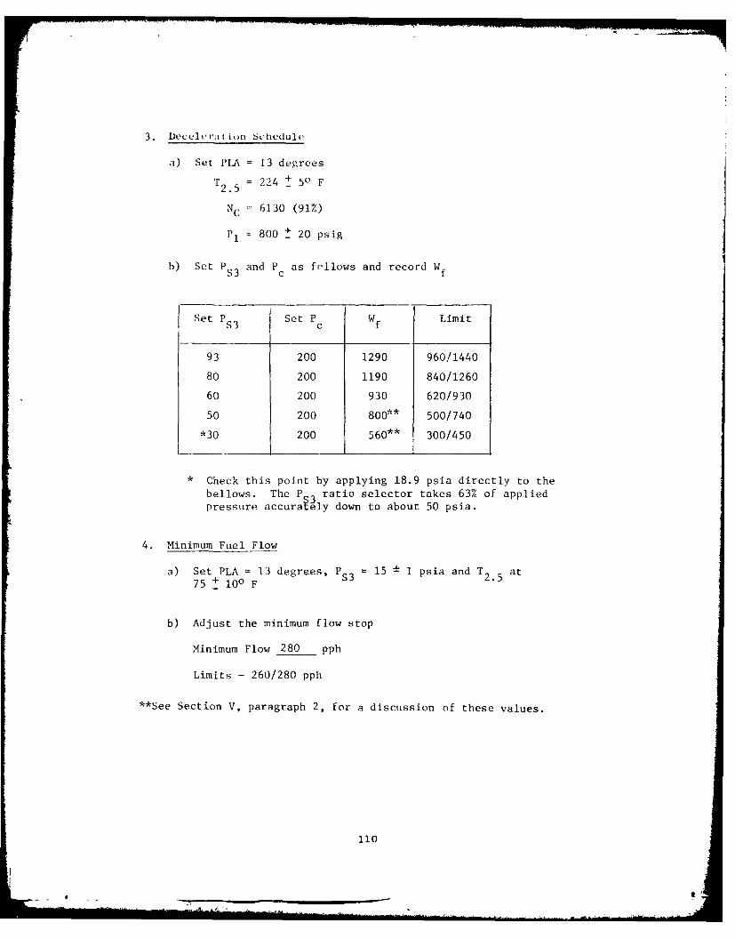
3. Deceleria t ijn Schedule
a) Set PLA = 13 degrees
2.5 = 224 +
- 5 F
NC = 6130 (91%)
P1 = 800 t 20 psig
b) Set PS3 and Pc as frllows and record Wf
Set PS3 Set Pc Wf Limit
93 200 1290 960/1440
80 200 1190 840/1260
60 200 930 620/930
50 200 800** 500/740
*30 200 560** 300/450
* Check this point by applying 18.9 psia directly to the
bellows. The P 3 ratio selector takes 63% of appliedpressure accura ely down to about 50 psia.
4. Minimum Fuel Flow
a) Set PLA = 13 degrees, PS 3 = 15 1 1 psia and T 2.5 at
75 + 100 F
b) Adjust the minimum flow stop
Minimum Flow 280 pph
Limits - 260/280 pph
**See Section V, paragraph 2, for a discussion of these values.
110

5. Maximum and Idle Speed Adjustments
a) Set T2. 5 at 2240 F + 50 F
b) Set PLA, P 3 absolute, NC, P1 , and P as follows and set idleand maximum speed adjustments to get Wf within limits. Recordmeasured Wf*
PLA PS3 NC PI PC Wf Instructions
13 30 3370 400 200 740 Set Idle AdjustmentLimits: 600/750
92 217 6739 1000 500 8040 Set Max Adjustment
Limits: 7700/8500
11].

6. Acceleration Schedule
Set PLA, T2 .5 , NC, PI, Pc and PS3 absolute as indicated and record resulting
WI. (Barometric Pressure: psia)
Pt. PLA T2 .5 NC PI PC PS 3 Wf WNo. Deg. °F RPM ps g psig psia pph Limits, pph
1 92 224 6360 1000 200 * 33 1260 1270/1430
2 92 224 6360 1000 250 54 2120 2080/2340
3 92 224 6360 1000 250 67 2610 2575/2900
4 92 224 6360 1000 300 90 3530 3460/3900
5 92 224 6360 1000 400 104 4060 4000/4500
6 92 224 6360 1000 400 114 4440 4380/4970
7 92 224 6360 1000 500 144 5630 5540/6240
8 92 224 6360 1000 500 176 6800 6770/7630
9 92 224 6360 1000 600 222 8540 8540/9625
10 92 224 4770 500 200 54 1740 1580/1780
11 92 224 5175 500 250 67 2210 2010/2270
12 92 224 5565 750 300 90 3290 2930/3300
13 92 224 5710 750 400 104 3950 3480/3920
14 92 224 5840 1000 700 114 4620 3990/4500
15 92 224 6120 1000 500 144 5620 5410/6100
*Apply 21.0 psia directly to bellows chamber for this test point.
112

7. Core Stator Schedule Rc
a) Set PLA = 92 degrees
PS3 30 psia
Pc = 200 psi
P1 500 psi
b) Set T2 .5 and Nc as indicated and measure arm position.
Ret. Arm Pos. = 0.847T2. Sensor2.5 Limits: 0.827/0.867
S/N RPA - 04660
Point F/B Cable Pos.
No. T2 .5 NC Test Limits
1 56 6053 0.720 .680/.720
2 84 6220 0.722 .680/.720
3 120 6448 0.723 .680/.720
4 157 6668 0.720 .680/.720
5 224 6847 0.670 .625/.672
6 335 6809 .465/.523
7 157 6668 0.707 .680/.720
8 84 6448 0.724 .680/.720
9 56 6220 0.722 .580/.720
10 157 6739 .698/.743
11 157 6303 .563/.616
12 157 5634 .362/.422
13 157 4468 0/ .080
14 157 4125 0 (max)
15 157 6303 .563/.616
Hysteresis 7-4 = +0.013 Limit-
8-2 = +0.002 +.015
9-1 = +0.002
15-11=
113

V. Core Stator Schedule, $c
a) Set PLA =92 degrees
PS3 =30 psia
PC=200 psi
P, 250 psig
b) Set T2 .5 and NC as indicated and measure arm position.
T2 .5 Sensor Simulator Ret. Arm Pos. 0.847
SIN 1 3ALimits: 0.827/0.867
F/B Cable Pos. 0.847
Point T25psi N CNo. Test Limits
1 56 119 6053 0.715 .680/.720
2 84 125 6220 0.718
3 120 132 6448 0,720
4 157 139 6668 0.717
5 224 152 6847 0.667 .625/.672
6 335 175 6809 0.488 .465/.523
7 157 139 6668 .0703 .680/.720
8 84 125 6448 0.720 .680/.720
9 56 119 6220 0.718 .580/.720
10 157 139 6739 0.720 .698/.743
11 157 139 6303 0.622 .563/.616
12 157 139 5634 0.402 .362/.422
13 157 139 4468 0.026 0/.080
14 157 139 4125 -0.075 0 (max)
15 157 139 6303 0.614 .563/.616
Hysteresis 7-4 = -0.014 Limit-
8-2 =+0.002 +.015
9-1 = +0.003
15-11= -0.008
114

8. Droop Lines
a) Set T2 . 5 75 + 1 0 0 F
b) Set PIA, PS3' NC, and Pc as indicated and record Wf.
PIA PS3 Pc NC Wf Wf
Limits
13 30 200 3170 860
13 30 200 3270 780
13 30 200 3370 690 600/750
13 30 200 3470 610
13 30 200 3373 610 600/750
92 217 500 6540 8280
92 217 500 6640 8290
92 217 500 6739 8150 7700/8500
92 217 500 6840 7720
92 217 500 6739 8000 7700/8500
115

9. Electrical Overspeed Signal
a) Attach a continuity checker across pins one and twoat the overspeed switch connector.
b) Increase N Cuntil continuity occurs.
Indicated N0C 7020 rpm
Limits - 6975/7040
10. Hydromechanical Overspeed Limit
a) Set PI1 1000 psig
PC=500 psig
PS3 =217 psia
T25=75 +100 F
b) Increase NC until Wf is 500 + 100 pph.
Indicated N0C 7196 rpm
Limits- 71 75/7245
116

REFERENCES
1. Kast, Howard B., Hurtle, James E., and Poppel, Gary L., "BackupControl for a Variable Cycle Engine," Phase I Interim TechnicalReport, Air Force Aero Propulsion Laboratory, AFAPL-TR-77-92,December 1977.
117
mom=.

-7.4~.W~