CNESTEN DEVELOPMENT OF RADIOMETRIC … · development of radiometric methods for optimization of...
29
DEVELOPMENT OF RADIOMETRIC METHODS FOR OPTIMIZATION OF PHOSPHATE TRANSPORT PROCESS BY ''SLURRY PIPE'' S.MIMOUNT 1 , R.ALAMI 1 , O.HAKAM 2 , A.SAADAOUI 1 , K.ELKORCHI 2 1 NATIONAL CENTER OF ENERGY SCIENCES AND NUCLEAR TECHNIQUES –MOROCCO 2 UNIVERSITY OF IBN TOFAIL-KENITRA-MOROCCO CNESTEN
Transcript of CNESTEN DEVELOPMENT OF RADIOMETRIC … · development of radiometric methods for optimization of...

DEVELOPMENT OF RADIOMETRIC METHODS FOR
OPTIMIZATION OF PHOSPHATE
TRANSPORT PROCESS BY ''SLURRY PIPE''
S.MIMOUNT1, R.ALAMI1, O.HAKAM2, A.SAADAOUI1, K.ELKORCHI2
1NATIONAL CENTER OF ENERGY SCIENCES AND NUCLEAR TECHNIQUES –MOROCCO
2UNIVERSITY OF IBN TOFAIL-KENITRA-MOROCCO
CNESTEN
INTRODUCTION
Morocco can now lay claim to the largest phosphate
slurry pipeline system in the world.
The system consists of several pipelines totaling 235 km
in length. and transports 4400t/h of phosphate ore
The main delivery pipeline is 187 km long
The slurry pipeline represents an efficient transport
system, competitive and ecologically profitable.
With a total of 235 km of pipeline, Morocco will produce
38MT/Y of phosphate with a logistic cost reduction of
90%
CNESTEN

WHY SLURRY PIPELINES ?
Slurry pipelines have following advantages:
It can be able to move large amounts of coal over long distances.
Efficient cost with minimum potential for en-route environmental disruption.
Operating costs for labor is low.
More environmentally friendly
Two major disadvantages of slurry pipelines are:
Water requirements.
Low degree of operational flexibility.
CNESTEN

SLURRY TRANSPORTATION BY PIPELINE
Slurry Pipeline project needs its own specific study based on
following
Ore type
Ore characteristics
Water availability
Terrain conditions
Pipelines can be built in a variety of terrains, but it is in mountainous
regions that pipelines becomes particularly attractive
CNESTEN

HISTORICAL DEVELOPMENT OF SLURRY PIPELINES
Tab. 1: Examples of Slurry Pipelines Built Since 1957
CNESTEN

THE STUDY CONTEXT
The slurry pipelines platform is very complex by :
Its different mechanical components,
The particularity of the fluid
And the variable conditions of flow.
The application of radiation techniques on the
phosphate slurry pipe requires:
first a well understanding of how the slurry pipe system
is designed and a basic knowledge on slurry mixtures
behavior inside such equipment.
CNESTEN
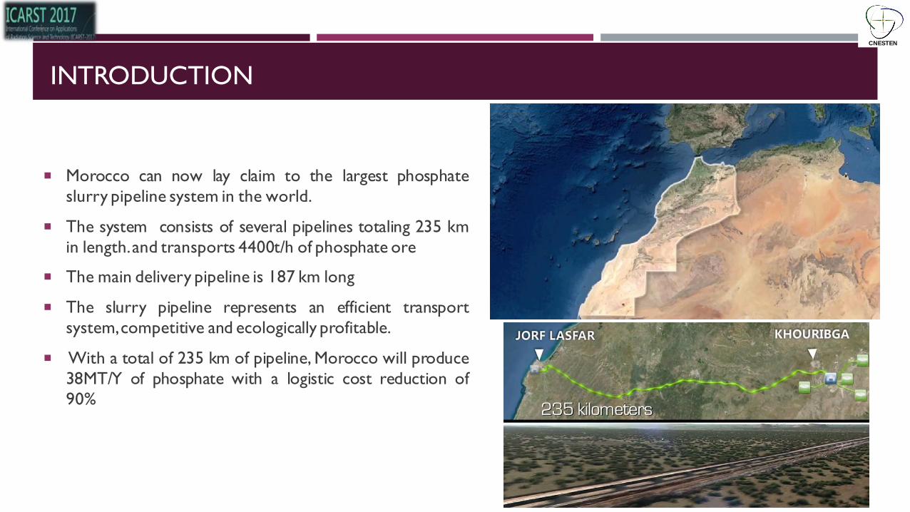
SLURRY PIPE SYSTEM DESCRIPTION
CNESTEN
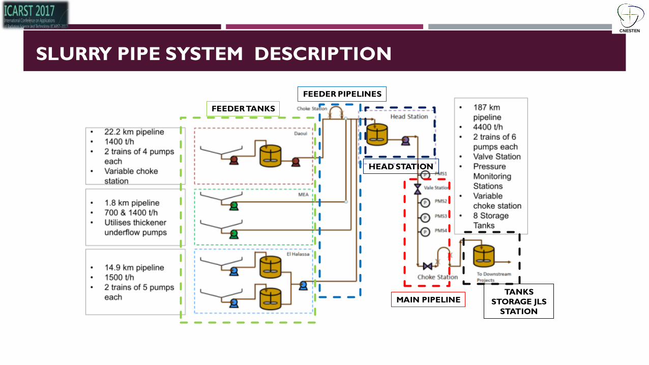
FEEDER TANKS
FEEDER PIPELINES
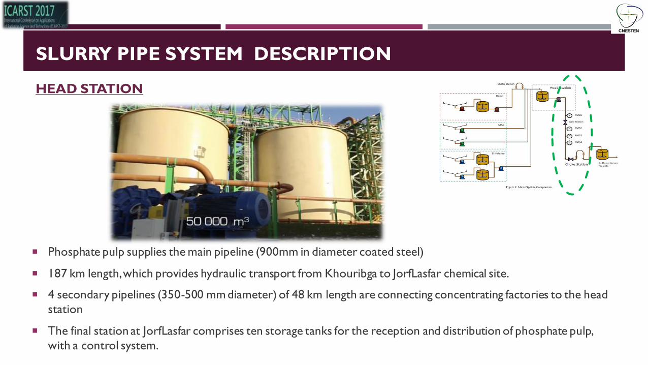
HEAD STATION
MAIN PIPELINE TANKS
STORAGE JLS
STATION

SLURRY PIPE SYSTEM DESCRIPTION
The raw phosphate, from different mines in Khouribga, is routed to four processing units (leaching
and flotation, 6,300 m3 each)
CNESTEN
FEEDER TANKS
SLURRY PIPE SYSTEM DESCRIPTION
Phosphate prepared for transport via (Slurry Pipeline). These units are equipped with milling systems
and sludge settling (thickeners) to prepare phosphate pulp for hydraulic pipeline systems.
CNESTEN
FEEDER TANKS

SLURRY PIPE SYSTEM DESCRIPTION
The ground pulp is thickened and stored in tanks at the exit of the concentrating factories and
pumped via pipelines to the secondary collection station called "head station".
CNESTEN
FEEDER PIPELINES
SLURRY PIPE SYSTEM DESCRIPTION
Phosphate pulp supplies the main pipeline (900mm in diameter coated steel)
187 km length, which provides hydraulic transport from Khouribga to JorfLasfar chemical site.
4 secondary pipelines (350-500 mm diameter) of 48 km length are connecting concentrating factories to the head
station
The final station at JorfLasfar comprises ten storage tanks for the reception and distribution of phosphate pulp,
with a control system.
CNESTEN
HEAD STATION

SLURRY PIPE SYSTEM DESCRIPTION
Khouribga-JorfLasfar pipeline is completely buried to a depth of two meters.
It is equipped with four intermediate pressure control stations, located every 40 kilometers, to provide direct pressure data required for the control system.
The pipeline is also equipped with a system of control and data acquisition (SCADA) to allow operators to manage, monitor and carry out all operations.
CNESTEN
MAIN PIPELINE

SLURRY AND SLURRY FLOWS
Slurry Slurry is essentially a mixture of solids and liquids; Its physical characteristics are dependent on many factors such as:
size and distribution of particles, concentration of solids in the liquid phase, 25-65%
size of the conduit (pipe diameter),
Level of turbulence,
temperature,
and Viscosity of the slurry (absolute or dynamic viscosity of the carrier).
CNESTEN

SLURRY AND SLURRY FLOWS
Slurry flows
The flow of slurry in a pipeline is much different from the
flow of a single phase liquid.
A two phase mixture, such as slurry, must overcome a
deposition critical velocity or a viscous transition critical
velocity. If the slurry’s speed of flow is not sufficiently high,
The particles will not be maintained in suspension. On the
other hand, in the case of highly viscous mixtures, if the
shear rate in the pipeline is excessively low, the mixture
will be too viscous and will resist flow
CNESTEN

MIXTURE CLASSIFICATION
Homogeneous (d ≤ 40):
Low solid concentration Newtonian
High solid concentration Non-Newtonian
There is little change in concentration within the pipe cross section
concentrate slurry after undergoing a process of grinding and thickening. Particles are then very fine and the
mixture is at a high concentration (50–60% by weight).
As the concentration of particles is increased . the mixture becomes more viscous and develops non-
Newtonian properties.
Typical particle sizes for homogeneous mixtures are smaller than 40µm to 70µm (325–200 mesh), depending
on the density of the solids.
CNESTEN

MIXTURE CLASSIFICATION
Pseudo-homogeneous (40 µm ≤ d ≤ 150 µm)
Under turbulent condition, the mixture can be transported with a uniform solid
concentration distribution across the pipeline .
Heterogeneous (0.15 mm ≤ d ≤ 1.5 mm)
For acceptable transport velocities, a solid concentration gradient exists over
the cross section of the pipe (vertical plane) .
CNESTEN
SLURRIES CRITICAL VELOCITIES
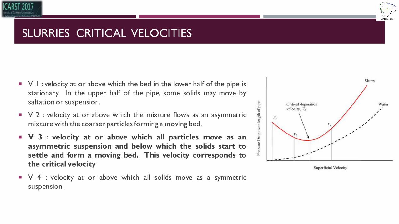
V 1 : velocity at or above which the bed in the lower half of the pipe is
stationary. In the upper half of the pipe, some solids may move by
saltation or suspension.
V 2 : velocity at or above which the mixture flows as an asymmetric
mixture with the coarser particles forming a moving bed.
V 3 : velocity at or above which all particles move as an
asymmetric suspension and below which the solids start to
settle and form a moving bed. This velocity corresponds to
the critical velocity
V 4 : velocity at or above which all solids move as a symmetric
suspension.
CNESTEN

CONTROL OF THE MAIN PIPELINE
Fig 8: Main Pipeline composents
Control of the pipeline must ensure:
No slack flow on the predominantly downhill
route profile
High enough velocity to avoid solids deposition
on pipe invert
Turbulent rather than laminar flow
Flow rate and pressure within the design limits
CNESTEN
CONTROL OF MAIN PIPELINE
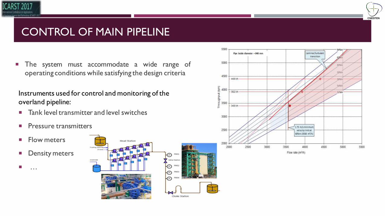
The system must accommodate a wide range of
operating conditions while satisfying the design criteria
Instruments used for control and monitoring of the
overland pipeline:
Tank level transmitter and level switches
Pressure transmitters
Flow meters
Density meters
…
CNESTEN

PROCESS ENGINEERING NEEDS AND PROPOSAL STUDIES
Risk of blockages
Accuracy of Flow meter value
Study
Evaluate the critical velocity and flow rate
Residence Time Distribution
More rheological information
Varying velocity,
Flow conditions
Varying Rheological proprieties.
Evaluate the efficiency of the flow meter system
CNESTEN
The new slurry pipe installed raises new challenges for radioisotope technology as applied to phosphate industry.
it is the first time such a material is transported by pipe over such long distances and the risk of blockages cannot be neglected.

PROCESS ENGINEERING NEEDS AND PROPOSAL STUDIES
1st
THE EVALUATION OF THE FLOW RATE OF THE SLURRY AT DIFFERENT POINTS AFTER THE
HEADING STATION
2sd
SLURRY PIPE WILL BE STUDIED IN ORDER TO EVALUATE THE
CRITICAL VELOCITY AND/OR TO MEASURE THE RTD OF THE FLUID ACCORDING TO THE NEEDS OF THE END USER
DEVELOPMENT OF TOMOGRAPHY SYSTEM FOR
CORROSION INSPECTION
The pipeline is DN 450 steel piping with high density
polyethylene (HDPE) internal lining.
EXT DIAM 900mm) The results compared to the measurements given by the flow
meters in place. This will allow the process engineers to
evaluate the efficiency of the installed equipment.
The radiotracer study scheduled for the next three months will concern
CNESTEN

1st : RADIOTRACER APPLICATION (FLOW RATE )
Tracer principle
1 • Design of tracer strategy together with processing engineers
2 • Selection of tracers
3 • Tracer mixture preparation, calibration
4 • Selection/design of tracer injection and sampling procedures
5 • Tracer injection
6 • Data evaluation
7 • Reporting of results.
A field radiotracer investigation consists, in brief, of the following
main steps :
CNESTEN

1st : RADIOTRACER APPLICATION (FLOW RATE )
Radioactive tracer s are used for the precise determination of the flow rate
Measuring the velocity or the flow rate of these components is difficult and frequently requires the use of non-
invasive methods
CNESTEN
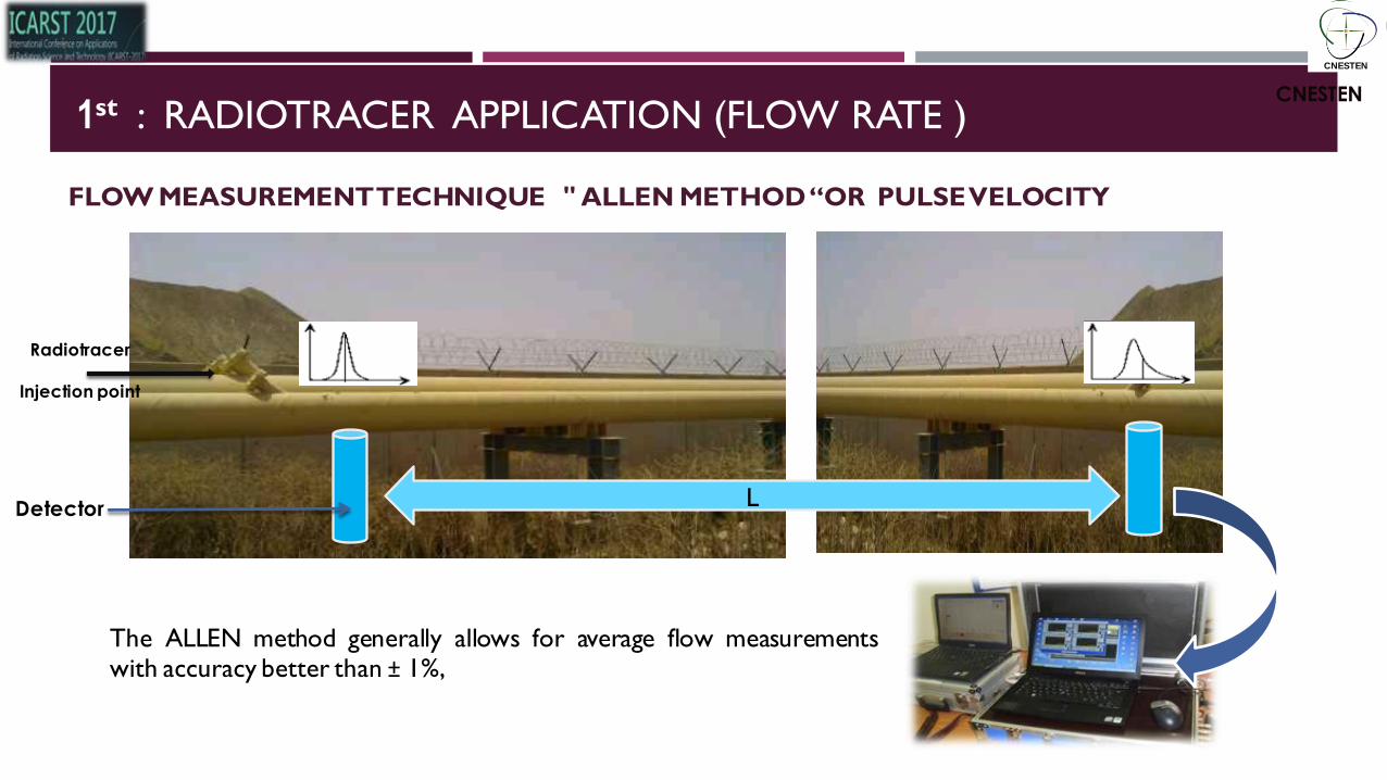
Radiotracer
Injection point
Detector L
CNESTEN
FLOW MEASUREMENT TECHNIQUE " ALLEN METHOD “OR PULSE VELOCITY
The ALLEN method generally allows for average flow measurements with accuracy better than ± 1%,
1st : RADIOTRACER APPLICATION (FLOW RATE )
CNESTEN

1st : RADIOTRACER APPLICATION (FLOW RATE )
Radiotracer Injection point (1st)
Detector (D1)
Detector (D2)
Detector (D3) Radiotracer Injection point (2nd)
Detector (D5’
Radioisotope I-131
The injection of tracers can be realized by various manners: very fast injection, injection with constant flow, injection
in a very high-pressure
CNESTEN
1st : RADIOTRACER APPLICATION (FLOW RATE )
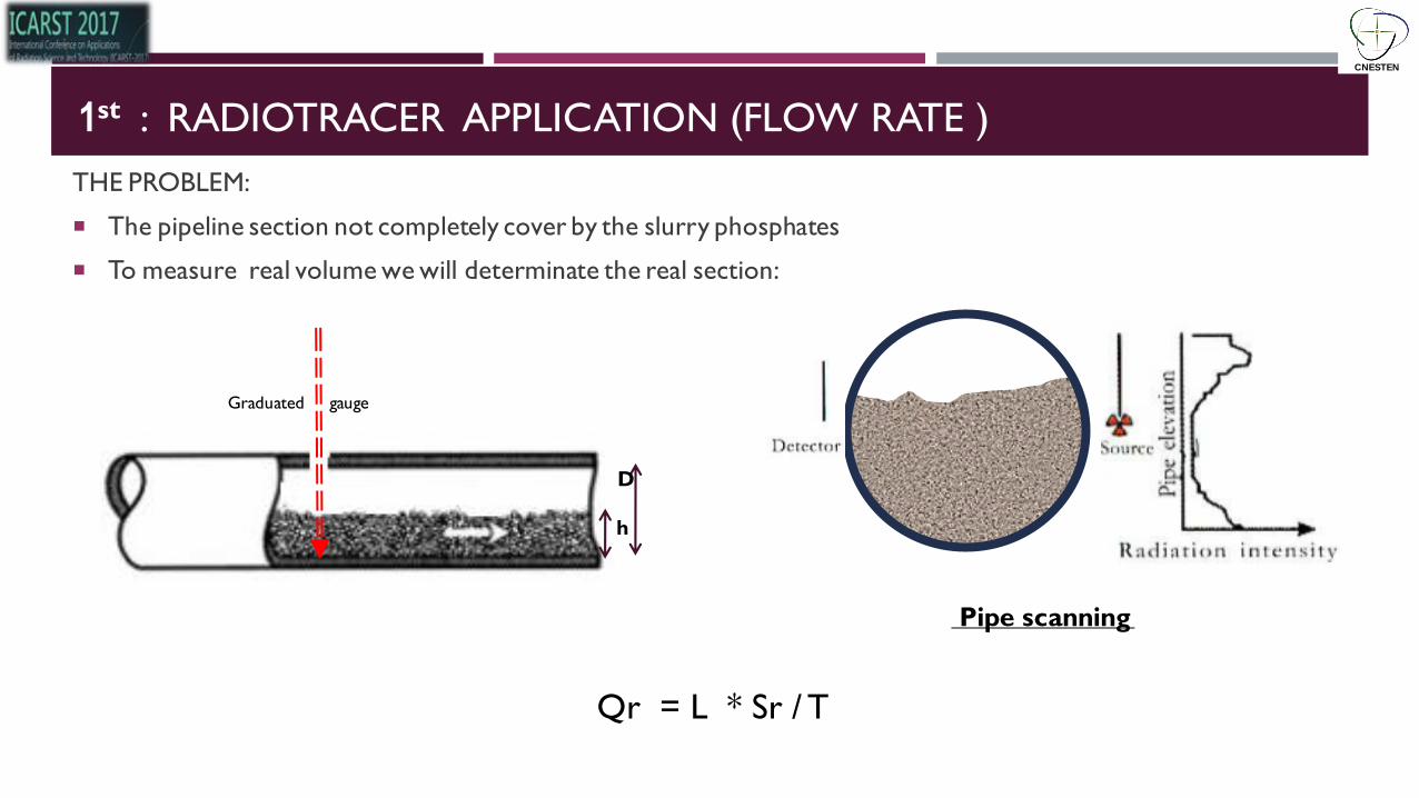
THE PROBLEM:
The pipeline section not completely cover by the slurry phosphates
To measure real volume we will determinate the real section:
Graduated gauge
D
h
Qr = L * Sr / T
Pipe scanning
CNESTEN

Calibration with the radiotracer transit time method :
Transit time method is commonly used in calibrating flow meters in processing pipes in closed conduits.
Covers a very large range of flow speeds, and reaches a small uncertainty without disturbing the process.
The distance between injection and measuring sections should be great enough to achieve adequate mixing of the
tracer with the water flowing in the conduit.
COMPARAISON WITH THE MEASUREMENTS GIVEN BY THE FLOW METERS IN
PLACE
This technique is already accepted as standard for flow meter calibration in several countries. Better than 1%
accuracy is achievable.
CNESTEN

1st : RADIOTRACER APPLICATION (FLOW RATE
This experimental study will take place in the next three months
The results will be exchanged with the tracer community interested
Your collaboration and your recommendations kindly requested.
CNESTEN

CNESTEN