CNC Router Part 2 Training Tutorial CNC Router Part 2 Training Tutorial Prepared by Steve Pilon -...
28
1 CNC Router Part 2 Training Tutorial Prepared by Steve Pilon - Version 1.1 September 2017 A – Index A- Index B- Intro C- Objective D- Required Items E- Opening CamBam and Loading a DXF F- Preparing Your Geometry And Saving G- Creating A Pocket H- Creating A Profile I- Set Post Processor And Posting Code J- Change Log B - Intro Note: This training assumes you have already taken part 1 per https://wiki.milwaukeemakerspace.org/trainingclasses/cncarea You will make the dish shown at the beginning of this document on the 4x8 router.
Transcript of CNC Router Part 2 Training Tutorial CNC Router Part 2 Training Tutorial Prepared by Steve Pilon -...

1
CNC Router Part 2 Training Tutorial
Prepared by Steve Pilon - Version 1.1 September 2017
A – Index
A- Index
B- Intro
C- Objective
D- Required Items
E- Opening CamBam and Loading a DXF
F- Preparing Your Geometry And Saving
G- Creating A Pocket
H- Creating A Profile
I- Set Post Processor And Posting Code
J- Change Log
B - Intro
Note: This training assumes you have already taken part 1 per
https://wiki.milwaukeemakerspace.org/trainingclasses/cncarea
You will make the dish shown at the beginning of this document on the 4x8 router.

2
While this tutorial may reference using other geometry (drawings) at times the only
allowed geometry for your part 2 training is the Part 2 Dish.dxf provided, no
exceptions.
Also this entire tutorial is in inches, for the part 2 training you MUST use inches!
After you have been signed off you are encouraged to use this guide as a
reference for future projects. After you are signed off you can of course talk to
Steve Pilon if you want him to “look over your shoulder”(not “do it for you”) for your
first fully independent project.
For clarity the period on some sentences has been omitted, such as when the
sentence ends with .250 (.250. could be misread as 250. instead of the intended
.250)
Please read the entire tutorial as there are lots of important items in here and if you
miss something you could damage the machine, your bit, or your workpiece. If your
tired go get some sleep, if you’re hungry go eat something, take your time and do
it right.
Important: While there are many things shown in this manual that also will translate very
nicely to using metal shop cnc machines such as the Tormach or the cnc parts of the
Bridgeport mill. This training (part 1, part 2 tutorial) DOES NOT COUNT AS TRAINING FOR
ANY METAL SHOP CNC MACHINES!!! Contact the proper persons for training on any metals
shop cnc machines or any other cnc machines other than the 4x8 router or the Mogul.
(Larry A. trains on the Tormach and Tom K. trains on the Bridgeport)
C - Objectives:
1. Import a 2d .dxf drawing into CamBam
2. Process the imported .dxf into a format suitable for CamBam
3. Understand and define a pocket and a profile toolpath and all associated
parameters.
4. Be able to visually inspect the generated toolpath.
5. Generate a working g-code file that can then be used on either the 4x8 cnc router
running Mach 3 or the Mogul running LinuxCNC.
D - Required Items:
1. This file
2. Part 2 Dish.dxf, this file is available from the wiki and also on the makervault

3
3. This tutorial must be done on a Milwaukee Makerspace computer as there are some
items in CamBam that are already set up especially for the 4x8 cnc router and the
smaller Mogul router. It’s helpful to use a dual monitor computer, open this manual on
one monitor and CamBam on the other.
4. A mouse with a scroll wheel, should be already on the Milwaukee Makerspace
computer.
5. The bit and the material are provided by the area for this training.
Conventions used in this manual:
1. I’m Curious: This is extra information, its not required to read, but there for additional
information.
2. Important: This is important information! Pay extra attention to this
Steps:
E - Opening CamBam And Loading A DXF
1. Load up CamBam on an available Milwaukee Makerspace computer per item 3
above by double clicking the CamBam icon on the desktop, or by finding CamBam in
the start menu. Note: The version may be different from this tutorial.
or
2. Change the units to Inches, if you draw something in a different unit, scale it in your
cad program to inches. Again the tutorial must be completed in inches using the
provided file.

4
3. After maximizing CamBam, select FileOpen. In the file type selector select DXF File
(*.dxf).
I’m Curious: While CamBam is able to import a .stl type file it can only be used for
creating true 3d profiles. .stl can NOT be used to generate profiles, pockets, engraves,
or drills, meaning you can not import a .stl from the internet for 3d printing into
CamBam and cut it out on the router. The dish you will create in this tutorial is defined
as 2.5d

5
4. Navigate to MAKERVAULT\CNC Area Training and select Part 2 Dish.dxf, then select
Open.
5. The .dxf drawing opens as shown below. You can roll your mouse wheel to zoom. You
can pan the view by holding down the center mouse button/wheel and moving the
mouse. Note: The X and Y axis and + - symbols are added here for clarity.

6
F - Preparing Your Geometry And Saving
6. We will need to rotate the part by 90 degrees to orientate the part on the table using
the hold down method as shown here.
7
7. Select the part as shown below. It will then turn red to show what is selected. You can
also individually select items by selecting them while holding down the Ctrl key.

8
8. Select EditTransformRotate. You will be prompted to select the rotation center
point, this is the point that your item will rotate around. Note the green text bar
prompting you what to do next shown in the second image.

9
9. Select the reference angle by clicking where the mouse pointer is shown in the first
image. Make sure that this is precisely vertical from the rotation center point selected
in the last step, else your part could be rotated crooked and cut at an angle. Select
the second point as shown in the second image, again being careful to select a point
that is precisely horizontal to the rotation center point. The part is now orientated
correctly for our planned cut as shown in step 6.

10
10. Select the small +(plus) sign next to 0. This expands the list of items in the drawing,
instead of having 2 polylines (the inner and outer rectangle with rounded corners) in
our drawing we have 16 separate items; this can be seen if we click on the part,
instead of the whole line being selected each individual segment is selected, we do
not want this.

11
11. Window select everything as shown in step 7 and then select EditJoin
12. A window will pop up asking you to enter the join tolerance, enter .1 and press ok. All
of the individual items are now turned into 2 clean polylines as shown in the second
image.
I’m Curious: While the exact number for this example is not super important what is
super important is that when you are generating your vector drawing in the future is
that you use your programs tool to precisely join the ends of lines together. AutoCAD
12
and other cad programs call these “object snaps”, Adobe Illustrator calls them “smart
guides”(you also need to use CTRL-J which executes the Join command), Coral uses
“snaps”, and Draftsight calls them “entity snaps”. You can play with this number if you
have been given a drawing that the creator has not correctly utilized snaps to
hopefully clean it up.
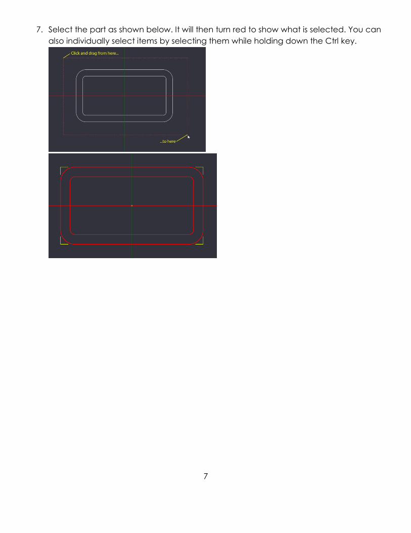
13. Now is a good time to save your working file. To do so either select File Save or
select the disk icon next to the units dropdown.
OR
14. A dialog box will pop up and prompt you to save your file. Enter your First and Last
name followed by Training Dish, if you name is John Smith then enter “John Smith
Training Dish”. Save the file on the local computer or your Makervault Location. Select
Save when you are finished to save your working file. It is a good idea to regularly save
your file throughout this tutorial.
G - Creating A Pocket
15. Our first operation will create the area shown with the coins in it, this area is called a
pocket since all of the material in cut away with the bit to create a void space. To
create the pocket, select the center line as shown and then select Machining

13
16. When the pocket is created it will automatically create Part1 under Machining. Click
on the word Basic/Advanced as shown in the second image until Basic is displayed,
this is actually showing the advanced options which we want.
17. You may want to adjust the display to more easily see more of the options, to do so
hover your mouse slightly above where the cursor is shown until the cursor turns into
what is shown in the second image, then click and drag the divider up some.

14
18. With Pocket1 selected under Part1 in the Machining tree we can set up the options for
the cut. While it is out of the objective of this document to explain every single one of
these options the important ones will be covered here. For more information on
options you can check out http://www.cambam.info/doc/plus/ however for the
purposes of this tutorial there is no need to. Listed below are the options, you will need
to scroll down using the scroll bar shown in image 1. We will use a lot of these same
options for the second operation called a profile which will cut out the part.
Pocket Options Under Advanced
1. Enabled: Controls whether the selected operation is posted out to the final g-code,
leave as True.
2. Name: You can change the name of the operation; this is useful for organizing
complex cuts with lots of different operations. We will leave it as the default
Pocket1.

15
3. Primitive IDs: Cut geometry can be selected by number instead of clicking as we
did earlier. We will leave this as the default since we have already used the mouse
to select the geometry(the inner rectangle)
4. Style: We do not need to change anything here.
5. Tag: We do not need to change anything here.
6. Clearance Plane: Here we set the height that the bit will go to when it is not in a
cut, as we are setting out Z origin/zero point at the top of the material to cut this will
be a positive number. Make sure this number is high enough to clear any clamps if
you will be machining near any. For the tutorial we will set our clearance plane to
.25
7. Depth Increment: CamBam can cut pockets by generating toolpaths at
progressively deeper cutting levels. The distance between each cut level is
specified in the Depth Increment. For the tutorial we will be using a .250 diameter
bit so we will set the depth increment to half the diameter of the bit or .125
8. Final Depth Increment: We will leave this value at the default of 0.
9. Stock Surface: This is the Z height that is the top of the stock (piece of wood). Again
the stock surface is going to be our origin/Z zero so will leave this item at 0.
10. Target Depth: Here we will enter the depth that our pocket will be relative to the
stock surface. Enter -.500 Note: Clearance Plane, Stock Surface and Target Depth
are all absolute values, if you forget the –(minus) sign here the router will go up in
the air above your part can act as if its cutting out your part, this is a common
mistake among beginners, remember the –(minus) sign!
11. Transform: We do not need to change anything here.
12. Feedrate: The speed in inches per minute that the bit will travel through the
material. When I meet you for the final cut I will give you recommended feedrates
and discuss some other federate topics.
13. Plunge Feedrate: Almost the same as above except in the Z axis (up and down).
14. The next 13 options we do not need to touch. See the above link if you want more
information.
15. Spindle Direction, Range, Speed: Currently none of the cnc machines that this
training cover have g-code based spindle control.
16. The next 6 items under the Step Over heading: Stepover is the amount that the bit
will move over when cutting a pocket, we will leave the defaults in place as they
work pretty good for any of the materials that can be cut using the cnc machines
for this training. If you want to play with these values after the tutorial keep in mind
that some of these values are % of the diameter of the bit.
17. Tool Diameter: This is the diameter of the bit you are using. If you are doing
something like an engrave or you want to cut directly on the line for a profile cut

16
you can enter .001 For the tutorial we will be using a .250 bit so enter .250 for the
tool diameter.
18. Tool Number: This can be used if you are changing bits mid cut, an advanced
procedure. For the tutorial we will leave this value as 0.
19. Tool Profile: We do not need to change anything here.
Alright! We have now entered the parameters for the pocket. As stated earlier
many of these parameters will carry over to cutting the part out using profile.
19. Right click on Pocket1 and select Generate Toolpaths, CamBam uses our parameter
we entered above to show the center of the toolpaths as blue lines as shown below.
Where the yellow arrow is by the mouse pointer is the start of the cut and the direction
of the cut.

17
20. By holding the ALT key and the left mouse button we can rotate our view from 2d to
3d and see the depth of the passes we set above under the depth increment. Here
there are 4 passes, this is especially visible below in the lower right corner by the mouse
pointer. Visible here is also 2 vertical dashed red lines, these lines indicate where the bit
will plunge and retract from each depth increment.
21. We can change our view to the side of the part by selecting ViewYZ Plane. In the YZ
plane the multiple depth passes and dashed plunge and retract lines are clearly
visible.
22. While you can generate machining operations in any view it will be easier to select
them in our original top view or XY plane. To return to the top view, as before, select
ViewXY Plane.
18
H - Creating A Profile
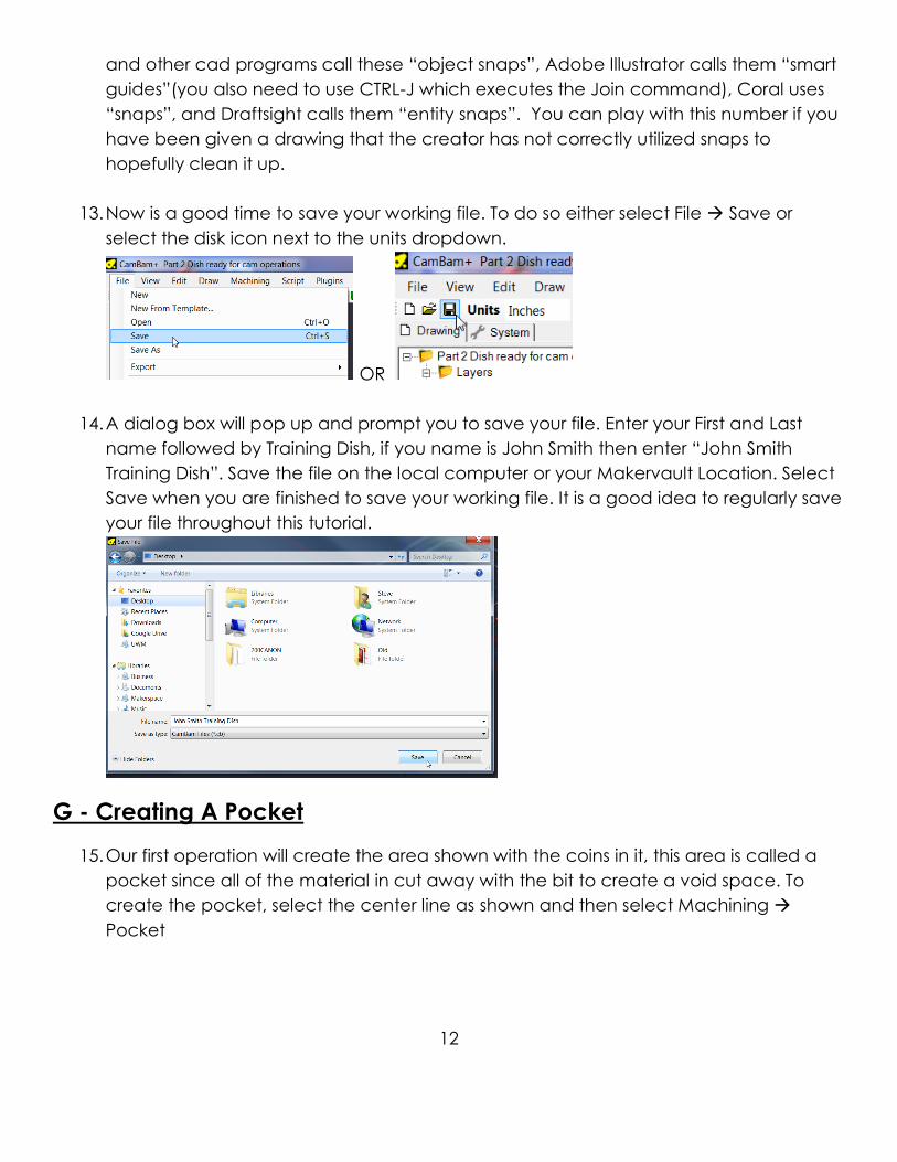
23. To create the machining operation that will cut the part out from the wood select the
outer polyline, then select MachiningProfile.
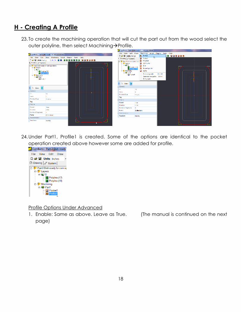
24. Under Part1, Profile1 is created. Some of the options are identical to the pocket
operation created above however some are added for profile.
Profile Options Under Advanced
1. Enable: Same as above. Leave as True. (The manual is continued on the next
page)

19
2. Inside/Outside: Only used for profiles. Controls what side of the polyline the bit will
cut on. In step 20 we selected the polyline, however CamBam only sees this as a
polyline, it does not know that this is the outside of part. When clicking the
dropdown button we have two options, Outside or Inside. Selecting either of these
options will change the side of the line the bit will cut on as shown by the blue and
green lines in the images below. We will select the Outside option for the tutorial.
(The below images are for illustrating the difference between outside and inside.
DO NOT USE ANY OF THE SHOWN SETTINGS!!!)
3. Name: Same as above. Leave as Profile1
4. Primitive IDs: Same as above. Do not change.
5. Style: Same as above. Leave blank.
6. Tags: Same as above. Leave blank.
7. Clearance Plane: Same as above. Set at .250
8. Depth Increment: Same as above. Set at .125
9. Final Depth Increment: Same as above. Leave at 0
10. Stock Surface: Same as above. Set at 0
11. Target Depth: Similar to the pocket setting but here we will enter the thickness of
the material as measured by a caliper. Normally you will also add about .050 to the
thickness of the part to ensure that your part will be cut out all the way through. For
the time being enter -.75, we will measure the material before we cut and enter the
actual value.
Important: When purchasing items such as MDF, plywood or plastics it is sold as ½”,
¾” etc thicknesses. These thicknesses are nominal, entering .500 or .750 as the
Target Depth will result in either your part not being fully cut out(you will then need
to do a bunch of laborious manual hand cutting) or cutting too deep and going
too far into the table. ALWAYS use a caliper to measure the thickness of your
material, its best to measure in a couple different places and take a rough
average.
12. Transform: We do not need to change anything here, leave blank.

20
13. Cut Feedrate: The speed in inches per minute that the bit will travel through the
material. When I meet you for the final cut I will give you recommended federates
and discuss some other federate topics.
14. Plunge Feedrate: Almost the same as above except in the Z axis(up and down).
15. We can ignore the next 5 items as they are outside the scope of this document.
16. Holding Tabs: We will come back to this tab later in the tutorial.
17. Lead in Move & Lead out Move: These control how the bit will enter and exit the
cut, they can be useful for metal cutting cnc machines. For this tutorial we will
leave them in their default state of None to have the bit plunge inline with the cut.
18. Side Profile: For more information:
http://www.cambam.info/doc/plus/cam/SideProfiles.htm Leave at the default
value of None.
19. For the next 6 options we will leave these at the default, if you would like to learn
more about them you can find more info here:
http://www.cambam.info/doc/plus/cam/Profile.htm
20. Spindle direction, range, and speed: These options control the spindle, for the time
being our spindle on the 4x8 router and the Mogul are manually controlled. These
settings do not matter now.
21. Step Over Categories: (Cut Width, Max Crossover Distance, Roughing Clearance,
Step Over, Stepover Feedrate) All of these are applicable to metal cutting using
CamBam, this topic is outside of the scope of this document. For more information
see the above /profile.htm link.
22. Tool Diameter: This is the diameter of the tool. Entering this number correctly is
critical for having your final part be the right size. We will be using a ¼” endmill so
enter .25 here.
23. Tool Number: Each tool you use can be assigned a number, since we are only using
one tool for this tutorial leave this value at the default of 0.
24. Tool Profile: This feature is not yet implemented in CamBam so we will ignore it.
25. After carefully entering all of the above parameters right click on Profile1 and select
Generate Toolpaths. The outside Profile1 tool path is generated as shown below.

21
26. We can rotate the part as part as described in step 18 by holding ALT and the left
mouse button. This will reveal the toolpaths as shown below. The problem here is that
the bit will cut the dish out entirely and there is a potential for the dish to break loose
and jam in between the bit and the stock breaking the bit or marring the dish, to avoid
this we will go back and add something called tabs. Tabs will form bridges which will
keep the part connected to the stock which we will then go and cut off manually.

22
27. Select Profile1 and then click the + symbol next to Holding Tabs as shown below.
28. In the menu you expanded in the last step change Tab Method to Manual
29. Enter the following parameters:
1. Width: The width of the tab at its widest point if using triangle tabs, if your using
square tabs it’s the width of the entire tab. Enter .375.
2. Height: The height of the tab. Keep in mind that this height is measured from the
bottom of the piece so if you added some to your Target Depth then you need to
account for this so as not to have part of the tab be buried in the table. Enter .3
here.
3. Minimum Tabs: The minimum amount of tabs created in automatic tab creation.
4. Maximum Tabs: The maximum amount of tabs created in automatic tab creation.
5. Tab Distance: The distance between tabs created in automatic tab creation.
6. Size Threshold: Used such that if a source shape's perimeter is smaller that this value,
no holding tabs will be inserted for that shape.
7. Use Lead Ins: See http://www.cambam.info/doc/plus/cam/HoldingTabs.htm for
more information about lead ins and tabs in general if you would like. We will leave
this at the default of False
30. Reset the view to the top XY plane as before by clicking View XY Plane

23
31. Make sure Profile1 is selected.
32. Right click approximately where shown in the image below
33. In the menu that pops up select Holding Tabs Add Tab

24
34. A holding tab is created
35. Repeat the above from step 29 to add another tab as approximately as shown below.

25
36. Since we have changed our tool path we need to again select Profile1 and select
Generate Toolpaths to generate the tabs as shown below. Note where the mouse
pointer is below and how it shows a blank space with retract and plunge moves where
our two tabs will be located. These tabs will anchor our workpiece to the stock and
prevent it from breaking free and damaging the bit or/and workpiece.
37. Clicking on Part1 and selecting Generate Toolpaths will redraw the toolpaths for both
the pocket and the profile. You should see something similar to what’s shown below.

26
38. Alright everything is looking good here, for the 2nd part of the class you can now
schedule with Steve and he will pick up from here with you. If you are done with the
2nd part of the class and are already signed off we will continue on from here as a
refresher to posting the code out to the machine.
I - Set Post Processor And Posting Code
39. At the top of the screen select System
40. Click the + next to Post Processors to expand the list of post processors.
41. Each different g-code interpreter likes its g-code a little bit different. Different g-code
interpreters at Milwaukee Makerspace include:
1. 4x8 CNC Router: Mach3
2. CNC Mogul: LinuxCNC
3. Bridgeport Mill: Mach3
4. Tormach: This one is actually a LinuxCNC variant that Tormach has customized to its
liking.

27
42. To set the post processor Right click on the desired post and select Set as default.
43. The green arrow will move to the selected post processor.
44. Return to the Drawing tab and select the parts that you would like to post out to the
machine.
45. It’s always safe to Generate toolpaths again in case you made a change and forgot
to earlier.
46. Right click on the parts you would like to post and select Produce gcode
47. Name the file in the window that pops up and place the file where you would like to it
to be. This could be on the makervault, for makervault connected machines, or on
your usb drive.

28
48. Save your file and close CamBam by selecting File Exit
J – Change Log,
1.0 – Aug 22, 2017 - Initial draft
1.1 – Sep 7, 2017 - Fixed typos and clarified – to –(minus)