CNC 800 M - Fagor · PDF file- 3 - 2.1 MACHINE WITH MANUAL TOOL CHANGER Machine parameter...
201
CNC 800 M New Features (Ref.0204in)
Transcript of CNC 800 M - Fagor · PDF file- 3 - 2.1 MACHINE WITH MANUAL TOOL CHANGER Machine parameter...
CNC 800 MNew Features (Ref.0204in)
- 2 -
Version 2.1 (July 1995)
1. P627(1). DIVIDING FACTOR FOR ELECTRONIC HANDWHEEL FEEDBACKSIGNALS
Machine parameter P627(1) is used with P612(6), P626(6) and P627(6) which indicate the multiplying factor for the electronic handwheelfeedback signals for the X, Y and Z axis respectively.
Machine parameter P627(1) indicates whether all handwheel feedback signals are to be divided or not.P627(1)=0 They are not divided.P627(1)=1 All handwheel feedback signals are divided by two.
Examples for the X axis so the CNC assumes 100 pulses/turn with 25, 50 and 100 line handwheels:
25 line Fagor handwheel: P612(6)=0 and P627(1)=0 25 x 4 / 1 = 100 lines50 line Fagor handwheel: P612(6)=1 and P627(1)=0 50 x 2 / 1 = 100 lines100 line Fagor handwheel: P612(6)=1 and P627(1)=1 100 x 2 / 2 = 100 lines
Version 2.4 (June 1996)1. HANDWHEELS AFFECTED BY FEED-HOLD.
Until now, it was assumed that electronic handwheels operated like mechanical handwheels and, therefore, were not affected by Feed-hold.
However, some applications require the electronic handwheels (manual pulse generators) to be affected by Feed-hold.
Machine parameter "P628(2)" indicates whether they are or not affected by Feed-hold.
P628(2) = 0 Not affectedP628(2) = 1 Affected.
2. AUTOMATIC TOOL CHANGERS (ATC)With this feature, it is possible to manage tool changers at any time.
Until now, this was only possible while executing a program (P99996) in Automatic Mode.
Parameter setting:
Machine parameter "P628(3)" indicates whether the machine has an ATC or not.
P628(3) = 0 No ATC.P628(3) = 1 The machine has an ATC.
In either case, the CNC considers machine parameter "P743" and "P745" .
P743 Standard subroutine to be executed prior to a T functionP745 Standard subroutine to be executed after a T function
The subroutines associated with the T function must contain the tool selection sequence and must be defined by the manufacturerin one of the special ISO-coded user programs: P99994 or P99996.
Both subroutines are defined by an integer between 0 and 89.If set to 0, the CNC assumes that no subroutine is to be executed.

- 3 -
2.1 MACHINE WITH MANUAL TOOL CHANGERMachine parameter "P628(3)" must be set to "0" (no ATC available).
Basic operation in JOG or DRO mode
Every time a new tool is selected, (T?? - START), the CNC acts as follows:
1.- If machine parameter "P743" is set to a value other than "0", the CNC executes that standard subroutine.
2.- The CNC outputs the BCD code and assumes the new tool.
3.- If machine parameter "P745" is set to a value other than "0", the CNC executes that standard subroutine.
Basic operation while executing an automatic operation
Every time the execution of an automatic operation requires a tool change, (T01 active and the cycle requests T02), the CNC behavesas follows:
1.- If machine parameter "P743" is set to a value other than "0", the CNC executes that standard subroutine.
2.- It displays the message: "TOOL CHANGE" and interrupts program execution.
3.- When the operator presses the [CYCLE START] key, the CNC outputs the BCD code and assumes the new tool.
4.- If machine parameter "P745" is set to a value other than "0", the CNC executes that standard subroutine.
5.- The CNC resumes the execution of the automatic operation.
Basic operation while executing the ISO-coded user program (99996)
a) One or both machine parameters "P743" and "P745" have been set to a value other than "0".
Every time the execution of the ISO program (99996) requires a tool changer, the CNC behaves as follows:
1.- If machine parameter "P743" is set to a value other than "0", the CNC executes that standard subroutine.
2.- The CNC outputs the BCD code and assumes the new tool.
3.- If machine parameter "P745" is set to a value other than "0", the CNC executes that standard subroutine.
4.- The CNC resumes program execution.
b) Both machine parameters "P743" and "P745" have been set to "0".
Every time the execution of the ISO program (99996) requires a tool changer, the CNC behaves as follows:
1.- The CNC outputs the BCD code and assumes the new tool.
2.- It executes the internal standard subroutine N99, which:
Displays the message: "TOOL CHANGE"and interrupts program execution (M00).
3.- When the operator presses the [CYCLE START] key, the CNC resumes program execution.

- 4 -
2.2 MACHINE WITH AUTOMATIC TOOL CHANGER (ATC)Machine parameter "P628(3)" must be set to "1" (ATC available).
Basic operation in JOG or DRO mode
Every time a new tool is selected, (T?? - START), the CNC acts as follows:
1.- If machine parameter "P743" is set to a value other than "0", the CNC executes that standard subroutine.
2.- The CNC outputs the BCD code and assumes the new tool.
3.- If machine parameter "P745" is set to a value other than "0", the CNC executes that standard subroutine.
Basic operation while executing an automatic operation
Every time the execution of an automatic operation requires a tool change, (T01 active and the cycle requests T02), the CNC behavesas follows:
1.- If machine parameter "P743" is set to a value other than "0", the CNC executes that standard subroutine.
2.- The CNC outputs the BCD code and assumes the new tool.
3.- If machine parameter "P745" is set to a value other than "0", the CNC executes that standard subroutine.
4.- The CNC resumes the execution of the automatic operation.
Basic operation while executing the ISO-coded user program (99996)
a) One or both machine parameters "P743" and "P745" have been set to a value other than "0".
Every time the execution of the ISO program (99996) requires a tool changer, the CNC behaves as follows:
1.- If machine parameter "P743" is set to a value other than "0", the CNC executes that standard subroutine.
2.- The CNC outputs the BCD code and assumes the new tool.
3.- If machine parameter "P745" is set to a value other than "0", the CNC executes that standard subroutine.
4.- The CNC resumes program execution.
b) Both machine parameters "P743" and "P745" have been set to "0".
Every time the execution of the ISO program (99996) requires a tool changer, the CNC behaves as follows:
1.- The CNC outputs the BCD code and assumes the new tool.
2.- It executes the internal standard subroutine N99, which:
Displays the message: "TOOL CHANGE"and interrupts program execution (M00).
3.- When the operator presses the [CYCLE START] key, the CNC resumes program execution.
- 5 -
3. TREATMENT OF THE M19 (SPINDLE ORIENT)When using ATC, the spindle must be oriented before changing tools.
This features implements function M19 to manage spindle orientation.
M19 should be included in the standard subroutine to be executed before the T function (machine parameter P743).
Requirements:
The spindle must have a spindle encoder installed.
This encoder must be connected via connector "A5", which is the same one used for the electronic handwheel associated withthe Z axis.
To use this feature on machines having a handwheel associated with the Z axis, connector "A5" must be shared by the handwheeland the spindle encoder.
Precautions on machines having a Z axis handwheel:
· Both feedback devices must be commutated (handwheel and spindle encoder).
· The CNC interprets the feedback signals at connector "A5" as follows:
In "Spindle Orient" mode" (M19) as spindle feedback.In "Open Loop Spindle" mode (M3, M4, M5) as handwheel pulses.
· If the spindle switches from "Spindle Orient" mode to "Open Loop" mode without swapping the feedback device at connector"A5", the CNC will take the spindle pulses as handwheel pulses.
Parameter setting:
Machine parameter "P800" indicates whether there is a spindle encoder installed or not and, consequently, whether "SpindleOrientation" is available or not.
P800 = 0 No spindle encoder installed. "Spindle Orient" not available.P800 <>0 Spindle encoder line count (number of pulses/rev).
Besides having an spindle encoder (P800 other than 0), the following machine parameters must also be set:
P609(2) Spindle counting directionP700 Spindle speed when operating in M19P601(7) Sign of the spindle analog output associated with M19.P612(8) Type of spindle encoder reference mark (home).P619(6) Spindle orient in both directions (Negative S also possible).P719 Minimum analog spindle output when in M19.P717 Spindle in-position zone when in M19P718 Proportional gain K of the spindle when in M19P916 Spindle Orient position when executing M19 without an "S" value.
Programming format
Spindle Orient is programmed as: "M19 S4.3", where:
M19 Indicates that the spindle is now moving in Closed loop.S4.3 Indicates the number of degrees it has to move from the reference zero mark
Programming format while in DRO mode
To orient the spindle, proceed as follows:
* Press the keystroke sequence: [F] - [BEGIN] - [END]* The bottom of the CNC screen shows the letter "M"* Key in [1] - [9] - [S] - (desired value) - [CYCLE START]

- 6 -
Basic operation
A "M19 S4.3" type block is executed as follows:
* The CNC outputs the M19 code as any other "M" function so the electrical cabinet can execute it.
* If the spindle was in open loop (M3, M4), the CNC slows the spindle down until its speed is below the value set by machineparameter "P700" and, then, homes the spindle.
* The CNC orients the spindle to the preset position (S4.3) and at the speed set by machine parameter "P700".
If a block containing only an "M19" is executed (without "S4.3"), the CNC orients the spindle to the position set by machineparameter "P916". If "P916=0", the spindle spins indefinitely at the rpm set for M19.
The orienting direction is set by machine parameter "P601(7)"; however, the spindle may be oriented in either direction byusing machine parameter "P619(6)".
* The spindle will remain in closed loop until:
- An M3, M4 or M5 is executed- An S ???? is executed- A Reset is carried out- An M30 is executed- An execution error comes up
Example:
M3 S1000 Spindle in open loop and turning clock-wise.M19 Spindle in closed loop, home search and orientation to position indicated by parameter "P916".M19 S100 Orient to 100° (from reference mark, home)S1000 Spindle in open loop recovering its previous turning direction (M3):M19 S200 Spindle in closed loop, home search and orientation to 200º from reference mark.

- 7 -
Version 3.1 (November 1997)
1. GENERATING AN ISO-CODED PROGRAMWith this CNC, the ISO code (low level) for an operation or a part-program may be generated.
To use this feature, machine parameter "P630(1)" must be set to "1".
This ISO program always has the number: 99996 and can be stored either at the CNC or at a PC.
Program 99996 is a special user program in ISO code and can be:Generated from an operation or a part-program.Edited at the CNC itself via menu option: "Auxiliary Modes - Edit program 99996"Loaded into the CNC after being generated at a PC.
Generating the ISO program (99996) at the CNC.
This CNC has 11 K of memory space to store program 99996. If the generated program is larger than that, the CNC will issue therelevant error message.
To generate program 99996, proceed as follows:
* If it is an operation, select or define the desired operation.
* If it is a part-program, select the desired one in the part-program directory and place the cursor on its header ("PART 01435".A listing of the operations it consists of must appear).
* Press the keystroke sequence: [CALC] [7]. The CNC will show the graphic simulation screen.
* Press . The CNC starts simulating the part and generating its ISO-coded program 99996.
* When done with the simulation, program 99996 stored in CNC memory will contain all simulated blocks in ISO code.
Generating the ISO program (99996) at a PC
Usually, the 99996 program generated from a part-program exceeds the available memory space of the CNC.
By using "DNC30", this program may be generated at a PC.
To do this, proceed as follows:
* Activate DNC communications and execute the DNC30 program at the PC.
* Select at the PC the menu option: "Program Management - Receive Digitizing".
* At the CNC, select the operation or place the cursor on the part-program header ("PART 01435"). A listing of the operationsit consists of must appear).
* Press [CALC] [8]. The CNC will display the graphic simulation screen.
* Press . The CNC starts simulating the part and generating program 99996.
* When done with the simulation, the 99996 program generated at the PC will contain all the blocks simulated by the CNC inISO code.
This program can be executed at the CNC through the menu option: "Execute infinite program" of the DNC30.
Note: While generating the ISO-coded program, no tool compensation is applied when simulating. However, the generatedprogram will have the corresponding G41 and G42.

- 8 -
2. RIGID TAPPING IS NOW AVAILABLEFrom this version on, typical tapping is possible (with a clutch) "P630(3)=0" as well as rigid tapping "P630(3)=1".
For rigid tapping, the CNC must control the spindle checking its turning speed at all times and supplying the necessary analog voltagefor the spindle to turn at the selected speed.
General considerations:
Rigid tapping is an interpolation between the spindle and the Z axis.The acceleration and deceleration time for the spindle and the Z axis should be the same.The following error (lag) of the spindle and that of the Z axis must be proportional. For example, if when tapping at F1000mm/min,
S1000rpm (pitch=1mm) the observed following error is Z=1mm and S=360º, it means that they are both perfectly synchronized.A machine parameter is now available to adjust the spindle's response (acc/dec) for each spindle range (gear).Since the Z axis gain is different for machining and for rigid tapping, the CNC offers 2 parameters, one for each case.Output THREADING_ON (I97) is active when carrying out a rigid tapping.
Machine parameters related to the spindle:
P800 Number of spindle encoder pulses (0...9999)P601(7) Sign of the analog S associated with M19 (0 or 1)P609(2) Spindle counting direction (0 or 1)P612(8) Type of spindle home marker pulse (0 = -, 1 = +)P719 Minimum spindle analog voltage (0...255)
P719=0 ==> 2,5 mV P719=10 ==> 25.0 mV (10 x 2.5)P719=1 ==> 2,5 mV P719=255 ==> 637.5 mV (255 x 2.5)
P717 In-position zone (dead-band) of the spindle. Number of encoder pulses (0...255)The CNC internally applies a x4 multiplying factor to the pulses coming from the encoder.Thus, with a 1000 line encoder and P717= 100, the in-position zone will be: (360°/4000)x100= ±9°
P718 Proportional spindle gain K (0...255)It sets the analog voltage corresponding to a following error of 1 spindle encoder pulse.
Analog (mV.) = P718 x Following error (pulses) x 2.5 mV / 64P751, P747, P748, P749 Duration of the spindle acc/dec ramp in ranges 1, 2, 3, 4 (0...255) Value 1=20 msP746 Feed-forward gain in rigid tapping (0...255)P750 Z axis proportional gain K1 in rigid tapping (0...255)P625(1) The tap entry is synchronized with the spindle home marker pulse (0=No, 1=Yes)
Feedback inputs:
P630(4) = 0 Connector A5 is used for spindle feedback and for the Z axis handwheel.Both feedback devices must be switched externally.
P630(4) = 1 Connector A5 is only used for spindle feedback.Connector A6 is used for the X axis handwheel.Connector A4 is used for Y and Z axes handwheels.PLC output O46 indicates which axis moves when turning the handwheel connected to A4."O46=0" for the Y axis and "O46=1" for the Z axis.
ISO Programming
It is programmed by means of function G33 (threading) indicating axis feedrate and spindle speed.Examples: G33 Z -10 F1000 S1000 M3 F1000 S1000 M3
G33 Z-10Functions G00, G01, G02 and G03 cancel function G33.
3. CURRENT CNC SOFTWARE VERSIONFrom this version on, when accessing the EPROM checksum screen [Auxiliary Modes] [Special Modes] [8]
The CNC will show the checksum of each EPROM and the current CNC software version. For example: Version 3.1
4. SCREEN SAVERWhen machine parameter “P626(7)=1” the screen saver function acts as follows:
After 5 minutes without pressing any key or the CNC not receiving any new data for refreshing (updating) the screen, it goesblank. Video is restored when pressing any key or when the CNC receives data to update the screen.

- 9 -
5. SEMIAUTOMATIC LINEAR MILLING
To access this mode, select the linear milling mode and press to get into semiautomatic mode.
This operation cannot be stored as in a part-program.
The path angle (α) and length (L) must be defined.
Jog the axes with the handwheel up to the starting point and press the corresponding JOG key (justpress it once, it does not have to be held down).
The axes will travel the indicated distance "L" in the indicated direction and at an angle "α" or until
the key is pressed.
6. SEMIAUTOMATIC ARC MILLING
To access this mode, select the arc milling mode and press to get into semiautomatic mode.
This operation cannot be stored in a part-program.
The rounding radius (R) must be defined. Its sign indicates the turning direction (R+ and R-)
Jog the machines with the handwheels to the desired starting point and press the corresponding JOG key (just press it once, it doesnot have to be held down). The machine will make a 90º arc in the indicated direction.
7. CROSS COMPENSATIONBesides compensating for measuring errors due to inaccurate leadscrews (leadscrew error), this CNC offers cross compensation inorder to compensate for errors caused by one axis onto another. A typical case would be beam (ram) sag compensation.
To use cross compensation, one must define the axis to be compensated and the one inflicting the error onto the other one whenmoving.
Machine parameters related to cross compensation:
P623(1) Cross compensation applied to the X axis (0=No, 1=Yes)P620(5) Cross compensation applied to the Y axis (0=No, 1=Yes)P620(4) Cross compensation applied to the Z axis (0=No, 1=Yes)P623(2), P623(3) Axis inflicting the error onto the other one.
Examples: Compensate Y for Z axis movementP620 ( * * * 1 0 * * *) P623 ( * * * * * 0 0 0)Compensate X for Y axis movementP620 ( * * * 0 0 * * *) P623 ( * * * * * 1 0 1)
8. FUNCTION M80 WHEN "Z" AS A DRO AXISThis feature is available when the Z axis is set to work as a DRO axis. "P617(4)=1".
Whenever the Z axis has to be moved, the CNC shows the text: "Act upon Z".Also, from this version on, it executes the auxiliary function M80. With this function, it is possible to act upon the hydraulic or mechanicaldevice that controls the Z axis.
Affected (compensated) axis Moving ("guilty") axis
P623(1) P620(5) P620(4) P623(3) P623(2)
X 1 0 0 X 0 1
Y 0 1 0 Y 1 0
Z 0 0 1 Z 1 1

- 10 -
9. MACHINE SAFETY REGULATIONThis CNC offers the following features to comply with machine safety regulations.
Enabling of the CYCLE START key from the PLC
This feature is available when machine parameter "P630(5)=1"
PLC output O25 indicates whether the CYCLE START key is enabled (=1) or not (=0)
Axes movements controlled by Feed-Hold. (It was already available)
Feed-Hold input, pin 15 of connector I/O 1, must be normally high.
If while moving the axes, the Feed-Hold input is brought low, the CNC keeps the spindle turning and stops the axes with 0V orvelocity command (analog signal) and keeping their enables ON.
When this signal is brought back up, the CNC will resume the movement of the axes.
Axes jogging feedrate limited by PLC.
This feature is available when machine parameter "P630(5)=1"
When activating PLC output O26, the CNC assumes the feedrate set by machine parameter "P814"
Handwheel managed by the PLC.
Machine parameter "P628(2)" indicates whether the axes movements with handwheels are affected by Feed-Hold (=1) or not (=0)
Machine parameter "P630(2)" indicates whether the multiplying factor indicated by the MFO switch position is applied (=0) orthe one indicated by the PLC outputs O44 and O45 (=1) (already available)
Spindle control from the PLC.
This feature is available when "P630(5)=1"
Output O27 =1 "tells" the CNC to apply the spindle analog voltage set by the PLC. The value of this analog signal is set at registerR156 and sent to the CNC by mark M1956.
R156= 0000 1111 1111 1111 => + 10V. R156= 0001 1111 1111 1111 => - 10V.R156= 0000 0111 1111 1111 => + 5V. R156= 0001 0111 1111 1111 => - 5V.R156= 0000 0011 1111 1111 => + 2,5V. R156= 0001 0011 1111 1111 => - 2,5V.R156= 0000 0000 0000 0000 => + 0V. R156= 0001 0000 0000 0000 => - 0V.
Also, PLC output O43, lets you control the rotation of the spindle. (Already available).It must be normally low.If it is brought up, the CNC stops the spindle.When it is brought back up, the CNC restarts the spindle.
Information for the PLC on the status of the machine reference (home) search
I88 Home search in progress.I100 X axis home search done.I101 Y axis home search done.I102 Z axis home search done.
O44 O45
0 0 According to switch setting
1 0 Same as x1 setting of the switch
0 1 Same as x10 setting of the switch
1 1 Same as x100 setting of the switch

- 11 -
Additional CNC information for the PLC
R120 The lower half of this register indicates the last key pressed.This value is maintained for 200 milliseconds unless another key is pressed before then.This register can be canceled from the PLC after being processed.
R121 bit 1 Indicates that the Milling operation is selected (=1)bit 2 Indicates that the Positioning operation is selected (=1)bit 3 Indicates that the Pocket Milling operation is selected (=1)bit 4 Indicates that the Boss Milling operation is selected (=1)bit 5 Indicates that the Corner Roughing operation is selected (=1)bit 6 Indicates that the Surface Milling operation is selected (=1)bit 7 Indicates that one of the machining operations (Center punching, Drilling, etc.) is selected (=1)bit 8 Indicates that the "Auxiliary Modes" option is selected (=1)bit 9 Indicates that the "Tool Calibration" option is selected (=1)bit 10 Indicates that the "Graphic Simulation" mode is selected (=1)bit 16 Indicates that the mode relevant to following cycle parameters: "finising pass, finishing feedrate, finishing tool and
safety distances on X and Z" is selected (=1)

- 12 -
Version 3.3 (March 1998)
1. MODULAR CNCThe modular 800M CNC consists of the Central Unit module (CPU), the Monitor and the keyboard.
Central Unit. It is usually located in the electrical cabinet and is mounted by means the holes it has for this purpose on its supportlid. Dimensions in mm.
When installing it, observe enough clearance to swing theCentral Unit open for future access to its interior.
To swing the central unit open, undo the two knurled nutsat the top and swing it open while holding its body.
Monitor. It may be mounted anywhere on the machine, preferably at operator's eye level.
9" Amber and 10" Color Monitor
1.- Contrast2.- Brightness3.- Two 3.15A/250V fast fuses (F), one per mains line, to protect the mains input.4.- Power switch.5.- 220 Vac mains and ground connection.6.- General ground connection terminal. Metric 6mm7.- 15-pin SUB-D type male connector for connecting it with the Central Unit.

- 13 -
14" Color Monitor
X2 15-pin SUB-D type male connector for connecting it with the Central Unit.1.- General ground connection terminal. Metric 6mm2.- 220 Vac mains and ground connection.
Monitor enclosures.
Keyboard. It may be mounted anywhere on the machine.
Rear panel
1.- 25-pin SUB-D type female connector for connecting it with the Central Unit.2.- Buzzer volume adjusting potentiometer.3.- Buzzer.
A, B, C, D E9" & 10 Monitor 25 mm 150 mm
14" Monitor 100 mm 50 mm

- 14 -
Connector for connecting the Central Unit with the Monitor.
FAGOR AUTOMATION provides the cable required for this connection. It comes with a 15-pin SUB-D type male connector atone end and a 15-pin SUB-D type female connector at the other.
Both connectors have a latching system UNC4.40 by means of two screws.
The supplied cable has 6 twisted pairs of 0.34 mm² wires (6 x 2 x 0.34mm²), with overall shield and acrylic cover. It has a specificimpedance of 120 Ohms. Its maximum length must be 25 meters (82 feet).
The cable shield is soldered to the metal hoods (housings) of both connectors and connected to pin 1 at both the Central Unitand Monitor/keyboard connectors.
Connector for connecting the Central Unit with the keyboard.
FAGOR AUTOMATION provides the cable required for this connection. It comes with a 25-pin SUB-D type male connector ateach end.
Both connectors have a latching system UNC4.40 by means of two screws.
The supplied cable has 25 wires of 0.14 mm² (25 x 0.14mm²), with overall shield and acrylic cover. Its maximum length must be 25meters (82 feet).
The cable shield is soldered to the metal hoods (housings) of both connectors and connected to pin 1 at both the Central Unitand Monitor/keyboard connectors.
ShieldHeat shrink
Outside shield solderedto metal hood
Metal hood
ShieldHeat shrink
Metal hood
Outside shield solderedto metal hood
PIN SIGNAL
1 GND
2 H
3 V
4 I
5 R
6 G
7 B
8 Not connected
9 Not connected
10 H
11 V
12 I
13 R
14 G
15 B
Metal hood Shield
PIN SIGNAL
1 GND
2 C9
3 C11
4 C13
5 C15
6 C1
7 C3
8 C5
9 C7
10 D1
11 D3
12 D5
13 D7
14 C8
15 C10
16 C12
17 C14
18 C0
19 C2
20 C4
21 C6
22 D0
23 D2
24 D4
25 D6
Metal hood Shield

- 15 -
2. PROGRAMMING IN ISO CODE. NEW FUNCTION F34P1 = F34 Parameter P1 takes the value of the tool causing the call to the subroutine associated with the tools.
Do not mistake it with function F24 which returns the number of the tool currently being used.
3. PROGRAMMING IN ISO CODE. RIGID TAPPINGWhen carrying out rigid tapping in 800M mode, the CNC acts as follows:
1.- Internally generates function M81 (switching feedback)2.- Carries out rigid tapping.3.- Internally generates function M82 (switching back to previous feedback)
Therefore, when programming rigid tapping in ISO code, function M81 must be programmed in block preceding rigid tapping andfunction M82 in the one following it.
4. 1000 LINE ENCODER AS A 1250 LINE ENCODERWith this feature, the CNC can use a 1000 line encoder as it were a 1250 line encoder.
P630(6) X axis 1000 line encoder as 1250 line encoder (0=No, 1=Yes)P630(7) Y axis 1000 line encoder as 1250 line encoder (0=No, 1=Yes)P630(8) Z axis 1000 line encoder as 1250 line encoder (0=No, 1=Yes)
A typical case: When using a motor with 1000 line encoder on a 5 mm pitch ballscrew.
The necessary calculations for setting axis resolution will be made using the selected line count (1000 or 1250 pulses).
5. PLCI. INPUT I104When the Feedrate Override Switch on the operator panel is set on one of the handwheel positions (x1, x10, x100), input I104 is setto "1".
6. PLCI. R120 AND THE KEY
From this version on, even when the is disabled by parameter P618(1), PLCI register R120 contains its code when it is pressed.
Version 3.04 (March 2002)1. TOOL COMPENSATION CANCELATION
Sometimes, it may be interesting to move the tool to a set position without applying its length compensation.In these cases, program "T.0" and the CNC will acts as follows:• It does not change the tool (it does not call its associated subroutine).• It cancels its associated offset (assuming a zero length and radius compensation).
The "T.xx" instruction may be programmed at any time, even inside the program P99996 or in its associated subroutine. The CNCassumes the new "xx" offset. When programming "T.0", it assumes a zero tool length and radius compensation.
2. FEEDBACK SIGNAL DIVIDING FACTORParameters P631(8), P631(7), P631(6), P631(5) and P631(4) are used with parameters P604(8), P604(7), P604(6), P604(5) and P616(8) thatindicate the multiplying factor for the feedback signals of the X, Y, Z, W, V axes respectively.
X axis Y axis Z axis W axis V axisP604(8) P604(7) P604(6) P604(5) P616(8)P631(8) P631(7) P631(6) P631(5) P631(4)
They indicate whether the feedback signals are divided (=1) or not (=0).P631(8)=0, P631(7)=0, P631(6)=0, P631(5)=0 and P631(4)=0 They are not dividedP631(8)=1, P631(7)=1, P631(6)=1, P631(5)=1 and P631(4)=1 They are divided by 2.
Example: To obtain a 0.01 mm resolution using a square-wave encoder mounted on the X axis whose pitch is 5 mm/turn.Nr of pulses = Leadscrew pitch / (Multiplying factor x Resolution)
If P604(8)=0 & P631(8)=0 x4 multiplying factor Nr of pulses = 125If P604(8)=1 & P631(8)=0 x2 multiplying factor Nr of pulses = 250If P604(8)=0 & P631(8)=1 x2 multiplying factor Nr of pulses = 250If P604(8)=1 & P631(8)=1 x1 multiplying factor Nr of pulses = 500

Headquarters (SPAIN): Fagor Automation S. Coop.Bº San Andrés s/n, Apdo. 144E-20500 Arrasate - MondragónTel: +34-943-719200/039800Fax: +34- 943-791712 +34-943-771118 (Service Dept.)www.fagorautomation.comE-mail: [email protected]
3. FEEDBACK FACTOR.The resolution of the axis is determined by the leadscrew pitch and the number of pulses of the encoder mounted on the motor.Sometimes, the resolution resulting from the available leadscrew / encoder combination does not match any of the resolution valuesallowed for the machine parameters (1, 2, 5, 10 microns or ten-thousandths of an inch).
Example: With a 6 mm/turn leadscrew pitch and a 2500 line encoder, the resulting resolution values are:Resolution = Leadscrew pitch / ( Nr of encoder pulses x multiplying factor).With x1 multiplying factor2.4 micron resolutionWith x2 multiplying factor1.2 micron resolutionWith a x4 multiplying factor 0.6 micron resolution
A new axis machine parameter is now available to solve these cases and it is referred to as Feedback Factor in order to adapt the resultingresolution to the existing setup.
P819 Feedback factor for the X axis P820 Feedback factor for the Y axis P821 Feedback factor for the Z axisValues between 0 and 65534, a "0" value means that this feature is not being used.
Use the following formula to calculate the "Feedback factor":Feedback Factor = (Gear ratio x Leadscrew Pitch / Encoder pulses) x 8.192
Examples: Gear ratio 1 1 2 1Leadscrew Pitch 4000 6000 6000 8000 (microns)Encoder 2500 2500 2500 2500 (pulses/turn)Feedback factor 13,107.2 19,660.8 39,321.6 26,214.4
The machine parameters only admit integers, but the Feedback Factor sometimes may have decimals. In those cases, set the machineparameter to the integer part of that value and use the leadscrew error compensation table to make up for the decimal part.
The values for this table are calculated using the following formula:Leadscrew position = Leadscrew error (microns) x Integer portion of feedback factor /Decimal portion of feedback factor
In this case: Gear ratio = 1 Pitch = 6000 Encoder = 2500Feedback factor = 19,660.8 Machine parameter = 19660For leadscrew error of 20 microns Leadscrew position = 20 x 19,660 / 0.8 = 491,520
The following table is obtained by using this calculation.Leadscrew position Amount of error at that positionP0 = -1966,000 P1 = -0.080P2 = -1474,500 P3 = -0.060P4 = -983,000 P5 = -0.040P6 = -491,500 P7 = -0.020P8 = 0 P9 = 0P10 = 491,500 P11 = 0.020P12 = 983,000 P13 = 0.040P14 = 1472,500 P15 = 0.060P16 = 1966,000 P17 = 0.080

FAGOR CNC 800M
INSTALLATION MANUAL
Ref. 9705 (in)

ABOUT THE INFORMATION IN THIS MANUAL
This manual is addressed to the machine manufacturer.
It includes the necessary information for new users as well as advanced subjects for thosewho are already familiar with the 800M CNC product.
It may not be necessary to read this whole manual. Consult the list of "New Features andModifications" and the appendix related to the machine parameters. Practically all of themare cross-referenced indicating the chapter and section of the manual where they are described.
This manual explains all the functions of the 800M CNC family. Consult the ComparisonTable for the models in order to find the specific ones offered by your CNC.
To install the CNC onto your machine, we suggest that you consult the appendix regardingthe enclosures required to mount the CNC as well as chapter 1 (CNC configuration) whichindicates the CNC dimensions and details the pin-out of its connectors.
Chapter 2 (Power and machine interface) shows how to connect the CNC to power A.C.(Mains) and to the electrical cabinet.
Chapter 3 "Auxiliary Functions" shows how to access special operating modes.
To adapt the CNC to the machine, set the CNC machine parameters. We suggest that youconsult chapters 4, 5, 6 and the appendices related to the machine parameters listed innumerical order.
Both appendices offer cross references indicating the section of the manual describing eachparameter.
When explaining each parameter in detail, chapters 4, 5 and 6, they sometimes refer tochapter 7 (concepts) where some of them are dealt with in further detail indicating how toperform various adjustments of the CNC-machine interface.
Once all machine parameters are set, we suggest that you write their settings down on thecharts provided for this purpose in the appendix on "Machine Parameter Setting Chart".
There is also an appendix on error codes which indicates some of the probable reasonswhich could cause each one of them.
Notes: The information described in this manual may be subject to variations due totechnical modifications.
FAGOR AUTOMATION, S.Coop. reserves the right to modify the contents of themanual without prior notice.

INDEX
Section Page
Comparison Table for Fagor 800T CNC models ........................................................ ixNew Features and modifications ................................................................................... xi
INTRODUCTION
Declaration of Conformity ............................................................................................ 3Safety Conditions ........................................................................................................... 4Warranty Terms .............................................................................................................. 7Material Returning Terms ............................................................................................. 8Additional Remarks ....................................................................................................... 9Fagor Documentation for the 800M CNC ................................................................... 10Manual Contents ............................................................................................................ 11
Chapter 1 CONFIGURATION OF THE CNC
1.1 Introduction ..................................................................................................................... 11.2 Dimensions and installation ............................................................................................ 21.3 Connectors and interface ................................................................................................. 31.3.1 Connectors A1, A2, A3, A4 ............................................................................................. 51.3.1.1 Dip-switches for connectors A1, A2, A3, A4 ................................................................... 61.3.2 Connector A5 .................................................................................................................. 71.3.2.1 Dip-switches for connector A5 ........................................................................................ 81.3.3 Connector A6 .................................................................................................................. 91.3.4 RS232C connector .......................................................................................................... 101.3.5 Connector I/O 1 ............................................................................................................... 131.3.5.1 Inputs of connector I/O 1 ................................................................................................. 141.3.5.2 Outputs of connector I/O 1 .............................................................................................. 171.3.6 Connector I/O 2 ............................................................................................................... 191.3.6.1 Outputs of connector I/O 2 .............................................................................................. 20
Chapter 2 POWER AND MACHINE INTERFACE
2.1 Power interface ................................................................................................................ 12.1.1 Internal power supply ...................................................................................................... 12.2 Machine interface ............................................................................................................ 22.2.1 General considerations .................................................................................................... 22.2.2 Digital outputs ................................................................................................................. 42.2.3 Digital inputs ................................................................................................................... 42.2.4 Analog outputs ................................................................................................................ 52.2.5 Feedback inputs ............................................................................................................... 52.3 Set-up ............................................................................................................................... 62.3.1 General considerations .................................................................................................... 62.3.2 Precautions ...................................................................................................................... 62.3.3 Connection ...................................................................................................................... 72.3.4 System input/output test ................................................................................................. 82.4 Emergency input/output connection .............................................................................. 102.5 Activation / Deactivation of external devices ................................................................. 13

Section Page
Chapter 3 AUXILIARY FUNCTIONS
3.1 Millimeters / Inches ......................................................................................................... 13.2 Tool length compensation .............................................................................................. 13.3 Tool Table ....................................................................................................................... 23.3.1 Modification of tool dimensions ..................................................................................... 33.4 Tool calibration ............................................................................................................... 43.5 Execution / Simulation of program P99996 .................................................................... 53.5.1 Execution of program P99996 ........................................................................................ 53.5.1.1 Tool inspection ............................................................................................................... 63.5.1.2 Execution modes ............................................................................................................. 73.5.1.3 CNC reset ......................................................................................................................... 73.5.1.4 Displaying program blocks ............................................................................................. 73.5.1.5 Display modes ................................................................................................................. 83.5.2 Simulation of program 99996 ......................................................................................... 103.5.2.1 Zoom function ................................................................................................................. 113.6 Auxiliary modes .............................................................................................................. 123.7 Special modes .................................................................................................................. 123.7.1 Test .................................................................................................................................. 133.7.2 General parameters .......................................................................................................... 153.7.3 Decoded "M" functions ................................................................................................... 163.7.3.1 M functions sent out in BCD........................................................................................... 183.7.4 Leadscrew error compensation ........................................................................................ 193.8 Peripherals ....................................................................................................................... 213.8.1 Peripheral mode ............................................................................................................... 213.8.2 DNC communications ..................................................................................................... 223.9 Lock / unlock .................................................................................................................. 233.10 Editing program P99996 ............................................................................................... 24
Chapter 4 MACHINE PARAMETERS
4.1 Introduction ..................................................................................................................... 14.2 Operating with parameter tables ...................................................................................... 24.3 General machine parameters ............................................................................................ 34.3.1 Input/output parameters .................................................................................................. 54.3.2 Parameters related to the handwheels .............................................................................. 104.3.3 Parameters related to the operating mode........................................................................ 124.3.4 Parameters for the RS232C serial line ............................................................................. 16
Chapter 5 MACHINE PARAMETERS FOR THE AXES
5.1 Parameters related to axis resolution ............................................................................... 25.2 Parameters related to the analog outputs ......................................................................... 55.3 Parameters related to travel limits ................................................................................... 65.4 Feedrate related parameters ............................................................................................. 75.5 Parameters related to axis control .................................................................................... 95.6 Parameters related to machine reference zero .................................................................. 115.7 Parameters for acceleration/deceleration of the axes ....................................................... 135.7.1 Linear acceleration/deceleration ..................................................................................... 135.7.2 Bell-shaped acceleration/deceleration ............................................................................ 145.7.3 Feed-forward gain ............................................................................................................ 155.8 Leadscrew related parameters .......................................................................................... 165.8.1 Leadscrew backlash ......................................................................................................... 165.8.2 Leadscrew error ................................................................................................................ 175.9 Special machine parameters ............................................................................................ 19

Chapter 6 SPINDLE MACHINE PARAMETERS
6.1 Parameters related to spindle speed range change .......................................................... 16.2 Parameters for analog spindle speed output .................................................................... 26.3 Parameters for spindle speed output in BCD ................................................................... 3
Chapter 7 CONCEPTS
7.1 Feedback systems ............................................................................................................ 17.1.1 Counting frequency limits .............................................................................................. 27.2 Movement by electronic handwheel ............................................................................... 37.3 Axis resolution ................................................................................................................ 47.4 Adjustment of the axes .................................................................................................... 107.4.1 Adjustment of the drift (offset) and maximum feedrate (G00) ......................................... 117.4.2 Gain adjustment ............................................................................................................... 137.4.3 Proportional gain adjustment .......................................................................................... 147.4.3.1 Calculation of K1, K2 and gain break-point ................................................................... 167.4.4 Feed-Forward gain adjustment ........................................................................................ 187.4.4.1 Calculation of feed-forward gain ..................................................................................... 187.4.5 Leadscrew error compensation ........................................................................................ 197.5 Reference systems............................................................................................................ 217.5.1 Reference points .............................................................................................................. 217.5.2 Machine reference (home) search .................................................................................... 227.5.3 Adjustment of the value corresponding to the machine reference point (home) ............ 237.5.4 Software travel limits for the axes ................................................................................... 247.5.5 Considerations about the machine reference point ......................................................... 257.6 Spindle ............................................................................................................................. 267.6.1 Spindle speed range change ............................................................................................ 297.7 Feedhold, transfer inhibit and M-done signal processing ............................................... 317.8 Auxiliary functions M, S, T ............................................................................................. 327.8.1 Decoded M function table ............................................................................................... 337.8.2 M, S, T function transfer .................................................................................................. 347.8.3 M, S, T function transfer using the M-done signal .......................................................... 35
APPENDICES
A Technical characteristics of the CNC .............................................................................. 2B Enclosures ....................................................................................................................... 4C CNC inputs and outputs .................................................................................................. 5D 2-digit BCD coded "S" output conversion table ............................................................. 6E Machine parameter summary chart .................................................................................. 7F Sequential machine parameter list ................................................................................... 10G Machine parameter setting chart ..................................................................................... 15H Decoded "M" function setting chart ................................................................................ 17I Leadscrew error compensation setting chart ................................................................... 18J Maintenance .................................................................................................................... 19
ERROR CODES
Section Page

COMPARISON TABLEFOR FAGOR 800M
CNC MODELS

AVAILABLE 800M CNC MODELS
800-MG 800-MGI
X, Y axes control l l
Z axis as DRO l l
Controlled Z axis l l
Spindle l l
Tools 99 99
Tool Radius Compensation l l
Tool Length Compensation l l
Electronic Handwheels 3 3
RS 232C Communications l l
Integrated PLC (PLCI) l
ISO-coded program editing(P99996)
l l
Execution of ISO-codedprogram (P99996)
l l
Graphics l l

Date: July 1995 Software version: 2.1 and newer
FEATURE AFFECTED MANUAL AND SECTION
Clear all arithmetic parameter contents setting Installation Manual Section 3.9them to "0". Operating Manual Section 3.8&6.9
ISO Programming. Programming Manual
Editing of program P99996 at the CNC. Installation Manual Section 3.10Operating Manual Section 3.9
When interrupting execution, the keys for the Installation Manual Section 3.5.1spindle, the coolant and for O1, O2, O3 and Operating Manual Section 2.5.1TOOL are enabled. Operating Manual Section 6.5
Subroutine associated to the execution of a tool Installation Manual Section 4.3(only when executing program P99996) Programming Manual Chapter 9.
ISO codes of the 800T CNC Programming Manual
NEW FEATURESAND
MODIFICATIONS
Date: November 1995 Software version: 2.2 and newer
FEATURE AFFECTED MANUAL AND SECTION
Subroutines to be executed before and after Installation Manual Section 4.3the "T" function. Programming Manual Chapter 9
"M" functions associated with automatic Operating Manual Section 4.1.2operations.
"M" functions associated with machining Operating Manual Section 5.1.1operations.

Introduction - 1
INTRODUCTION
Atention:Before starting up the CNC, carefully read the instructions of Chapter2 in the Installation Manual.
The CNC must not be powered-on until verifying that the machinecomplies with the "89/392/CEE" Directive.

Introduction - 3
DECLARATION OF CONFORMITY
Manufacturer: Fagor Automation, S. Coop.
Barrio de San Andrés s/n, C.P. 20500, Mondragón -Guipúzcoa- (ESPAÑA)
We hereby declare, under our responsibility that the product:
Fagor 800M CNC
meets the following directives:
SAFETY:
EN 60204-1 Machine safety. Electrical equipment of the machines.
ELECTROMAGNETIC COMPATIBILITY:
EN 50081-2 EmissionEN 55011 Radiated. Class A, Group 1.EN 55011 Conducted. Class A, Group 1.EN 61000-3-2 Current HarmonicsEN 61000-3-3 Voltage fluctuations and flickers
EN 50082-2 ImmunityEN 61000-4-2 Electrostatic Discharges.EN 61000-4-3 Radiofrequency Radiated Electromagnetic Fields.EN 61000-4-4 Bursts and fast transients.EN 61000-4-5 Conducted high voltage pulses in mains (Surges)EN 61000-4-6 Conducted disturbance induced by radio frequency fields.EN 61000-4-8 Magnetic fields at mains frequencyEN 61000-4-11 Voltage fluctuations and Outages.ENV 50204 Fields generated by digital radio-telephones
As instructed by the European Community Directives: on Low Voltage 73/23/CEE, onMachine Safety 89/392/EEC, 89/336/EEC on Electromagnetic Compatibility and itsupgrades.
In Mondragón, on October 1st, 2001

Introduction - 4
SAFETY CONDITIONS
Read the following safety measures in order to prevent damage to personnel, to thisproduct and to those products connected to it.
This unit must only be repaired by personnel authorized by Fagor Automation.
Fagor Automation shall not be held responsible for any physical or material damagederived from the violation of these basic safety regulations.
Precautions against personal damage
Use proper Mains AC power cablesTo avoid risks, use only the Mains AC cables recommended for this unit.
Avoid electrical overloadsIn order to avoid electrical discharges and fire hazards, do not apply electrical voltageoutside the range selected on the rear panel of the Central Unit.
Ground connectionIn order to avoid electrical discharges, connect the ground terminals of all the modulesto the main ground terminal. Before connecting the inputs and outputs of this unit, makesure that all the grounding connections are properly made.
Before powering the unit up, make sure that it is connected to groundIn order to avoid electrical discharges, make sure that all the grounding connections areproperly made.
Do not work in humid environmentsIn order to avoid electrical discharges, always work under 90% of relative humidity(non-condensing) and 45º C (113º F).
Do not work in explosive environmentsIn order to avoid risks, damage, do not work in explosive environments.
Precautions against product damage
Working environmentThis unit is ready to be used in Industrial Environments complying with the directivesand regulations effective in the European Community
Fagor Automation shall not be held responsible for any damage suffered or causedwhen installed in other environments (residential or homes).
Install the unit in the right placeIt is recommended, whenever possible, to instal the CNC away from coolants, chemicalproduct, blows, etc. that could damage it.
This unit complies with the European directives on electromagnetic compatibility.Nevertheless, it is recommended to keep it away from sources of electromagneticdisturbance such as.

Introduction - 5
- Powerful loads connected to the same AC power line as this equipment.- Nearby portable transmitters (Radio-telephones, Ham radio transmitters).- Nearby radio / TC transmitters.- Nearby arc welding machines- Nearby High Voltage power lines- Etc.
EnclosuresThe manufacturer is responsible of assuring that the enclosure involving the equipmentmeets all the currently effective directives of the European Community.
Avoid disturbances coming from the machine toolThe machine-tool must have all the interference generating elements (relay coils,contactors, motors, etc.) uncoupled.
Use the proper power supplyUse an external regulated 24 Vdc power supply for the inputs and outputs.
Grounding of the power supplyThe zero volt point of the external power supply must be connected to the main groundpoint of the machine.
Analog inputs and outputs connectionIt is recommended to connect them using shielded cables and connecting their shields(mesh) to the corresponding pin (See chapter 2).
Ambient conditionsThe working temperature must be between +5° C and +45° C (41ºF and 113º F)The storage temperature must be between -25° C and 70° C. (-13º F and 158º F)
Main AC Power SwitchThis switch must be easy to access and at a distance between 0.7 m (27.5 inches) and1.7 m (5.6 ft) off the floor.
Protections of the unit itself
It carries two fast fuses of 3.15 Amp./ 250V. to protect the mains AC input.
All the digital inputs and outputs have galvanic isolation via optocouplers between theCNC circuitry and the outside.
They are protected by an external fast fuse (F) of 3.15 Amp./ 250V. against reverseconnection of the power supply.

Introduction - 6
Precautions during repair
Do not manipulate the inside of the unitOnly personnel authorized by Fagor Automation may manipulate theinside of this unit.
Do not manipulate the connectors with the unit connected to AC power.Before manipulating the connectors (inputs/outputs, feedback, etc.)make sure that the unit is not connected to AC power.
Safety symbols
Symbols which may appear on the manual
WARNING. symbolIt has an associated text indicating those actions or operations may hurt peopleor damage products.
Symbols that may be carried on the product
WARNING. symbolIt has an associated text indicating those actions or operations may hurt peopleor damage products.
"Electrical Shock" symbolIt indicates that point may be under electrical voltage
"Ground Protection" symbolIt indicates that point must be connected to the main ground point of themachine as protection for people and units.

Introduction - 7
WARRANTY TERMS
WARRANTY
All products manufactured or marketed by Fagor Automation has a warranty period of12 months from the day they are shipped out of our warehouses.
The mentioned warranty covers repair material and labor costs, at FAGOR facilities,incurred in the repair of the products.
Within the warranty period, Fagor will repair or replace the products verified as beingdefective.
FAGOR is committed to repairing or replacing its products from the time when the firstsuch product was launched up to 8 years after such product has disappeared from theproduct catalog.
It is entirely up to FAGOR to determine whether a repair is to be considered underwarranty.
EXCLUDING CLAUSES
The repair will take place at our facilities. Therefore, all shipping expenses as well astravelling expenses incurred by technical personnel are NOT under warranty evenwhen the unit is under warranty.
This warranty will be applied so long as the equipment has been installed according tothe instructions, it has not been mistreated or damaged by accident or negligence andhas been manipulated by personnel authorized by FAGOR.
If once the service call or repair has been completed, the cause of the failure is not tobe blamed the FAGOR product, the customer must cover all generated expensesaccording to current fees.
No other implicit or explicit warranty is covered and FAGOR AUTOMATION shallnot be held responsible, under any circumstances, of the damage which could beoriginated.
SERVICE CONTRACTS
Service and Maintenance Contracts are available for the customer within the warrantyperiod as well as outside of it.

Introduction - 8
MATERIAL RETURNING TERMS
When returning the CNC, pack it in its original package and with its original packagingmaterial. If not available, pack it as follows:
1.- Get a cardboard box whose three inside dimensions are at least 15 cm (6 inches) largerthan those of the unit. The cardboard being used to make the box must have a resistanceof 170 Kg (375 lb.).
2.- When sending it to a Fagor Automation office for repair, attach a label indicating theowner of the unit, person to contact, type of unit, serial number, symptom and a briefdescription of the problem.
3.- Wrap the unit in a polyethylene roll or similar material to protect it.
When sending the monitor, especially protect the CRT glass.
4.- Pad the unit inside the cardboard box with poly-utherane foam on all sides.
5.- Seal the cardboard box with packing tape or industrial staples.
Introduction - 9
ADDITIONAL REMARKS
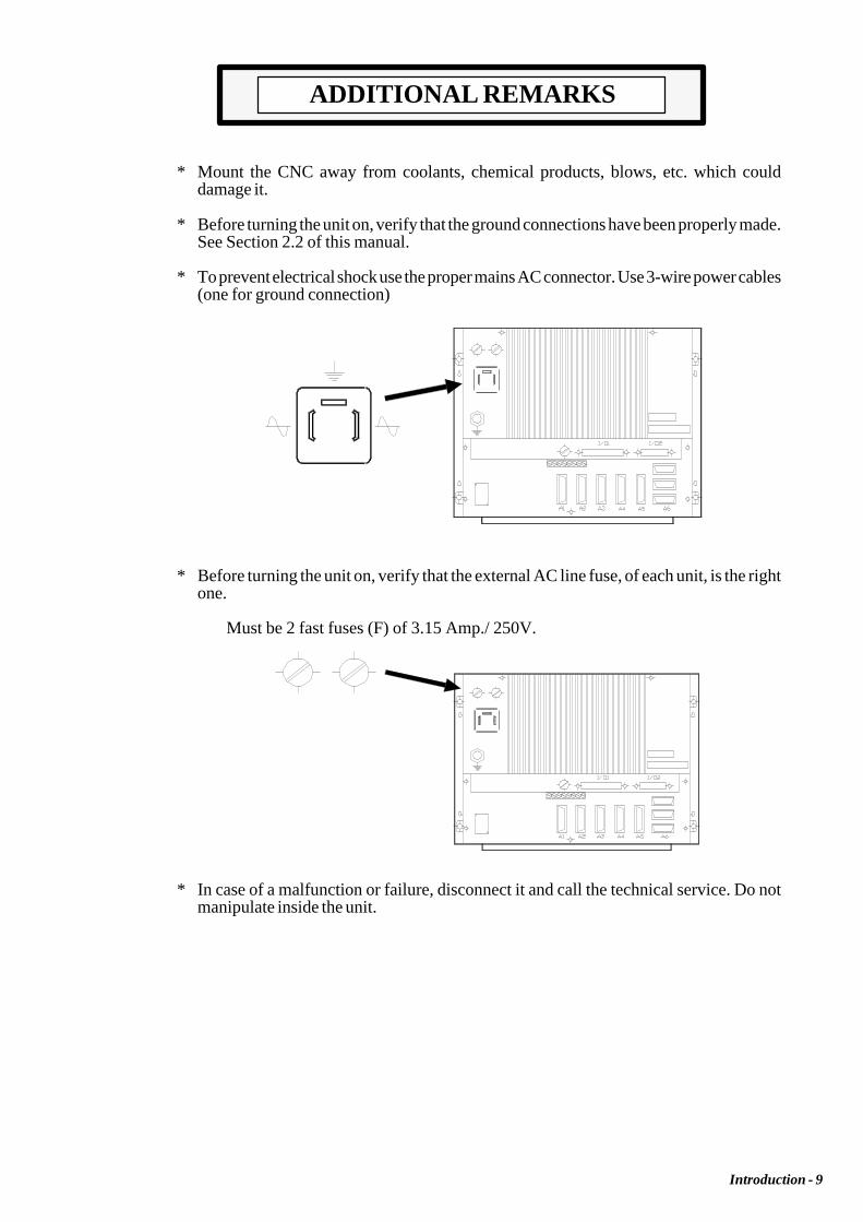
* Mount the CNC away from coolants, chemical products, blows, etc. which coulddamage it.
* Before turning the unit on, verify that the ground connections have been properly made.See Section 2.2 of this manual.
* To prevent electrical shock use the proper mains AC connector. Use 3-wire power cables(one for ground connection)
* Before turning the unit on, verify that the external AC line fuse, of each unit, is the rightone.
Must be 2 fast fuses (F) of 3.15 Amp./ 250V.
* In case of a malfunction or failure, disconnect it and call the technical service. Do notmanipulate inside the unit.

Introduction - 10
FAGOR DOCUMENTATIONFOR THE 800M CNC
800M CNC OEM Manual Is directed to the machine builder or person in charge of installing and startingup the CNC.
It has the Installation manual inside. Sometimes, it may contain an additionalmanual describing New Software Features recently implemented.
800M CNC USER Manual Is directed to the end user or CNC operator.
It contains 2 manuals:Operating Manual describing how to operate the CNC.Programming Manual describing how to program the CNC.
Sometimes, it may contain an additional manual describing New SoftwareFeatures recently implemented.
DNC 25/30 Software Manual Is directed to people using the optional DNC communications software.
DNC 25/30 Protocol Manual Is directed to people wishing to design their own DNC communications softwareto communicate with the 800 without using the DNC25/30 software..
PLCI Manual To be used when the CNC has an integrated PLC.
Is directed to the machine builder or person in charge of installing and startingup the PLCI.
DNC-PLC Manual Is directed to people using the optional communications software: DNC-PLC.
AUTOCAD 8050 Manual Is directed to people wishing to design their own customized CNC screens andsymbols on AUTOCAD. This manual indicates how to set up the Autocadprogram for the CNC to correctly interpret the designed screens and symbols.
FLOPPY DISK Manual Is directed to people using the Fagor Floppy Disk Unit and it shows how to useit.

Introduction - 11
MANUAL CONTENTS
The installation manual consists of the following sections:
Index
Comparative Table for Fagor 800M CNC models
New Features and modifications
Introduction Warning sheet prior to start-upDeclaration of ConformitySafety ConditionsWarranty termsShipping conditionsAdditional remarksFagor documents for the 800M CNCManual Contents
Chapter 1 CNC configurationIndicates the CNC dimensionsDetailed description of all the connectors.
Chapter 2 Power and machine connection.Indicates how to connect it to Main AC power.Ground connection.Characteristics of the digital inputs and outputs.Characteristics of the analog output.Characteristics of the feedback inputsCNC setup and start-upSystem I/O testingConnection of the Emergency input and output.How to activate and deactivate external devices.
Chapter 3 Auxiliary functions.Indicates how to select the work units (mm/inches).How to define the tool table.How to calibrate and inspect a tool.How to run a system test.How to access the machine parameters.How to access and operate with the decoded "M" functions.How to apply leadscrew error compensation.How to operate with peripherals.How to lock and unlock the machine parameters and the program memory.How to edit, execute and simulate program 99996.
Chapter 4 Machine parameters.How to operate with machine parameters.How to set the machine parameters.Detailed description of the general machine parameters.
Chapter 5 Machine parameters for the axes.Detailed description of the machine parameters for the axes.
Chapter 6 Machine parameters for the spindle.Detailed description of the machine parameters for the spindle.
Chapter 7 Concepts.Feedback systems, resolutionAdjustment of the axes and their gains.Reference Systems: Reference systems, search and settingSoftware travel limits for the axes.Acceleration / deceleration.Spindle: speed control and range change."Feed Hold" and "M-done" signal processing (treatment)Auxiliary M, S, T function transfer

Introduction - 12
Appendix A CNC technical characteristics.B Enclosures.C CNC inputs and outputs.D 2-digit BCD coded spindle "S" outputE Machine parameter summary chartF Sequential machine parameter listingG Machine parameter setting chartH Decoded "M" function chartI Leadscrew error compensation tableJ Maintenance
Error Code

PageChapter: 1 Section:
CONFIGURATION OF THE CNC 1INTRODUCTION
1. CONFIGURATION OF THE CNC
Atention:
The CNC is prepared to be used in Industrial Environments, especiallyon milling machines.
It can control machine movements and devices.
1.1 INTRODUCTION
The 800M CNC is an enclosed compact module whose front view offers:
1. An 8" monochrome amber monitor or CRT screen used to display the requiredsystem information.
2. A keyboard which permits communications with the CNC; being possible torequest information or change the CNC status by generating new instructions.
3. An operator panel containing the necessary keys to work in JOG mode as wellas the Cycle Start/Stop keys.

Section:Chapter: 1Page
CONFIGURATION OF THE CNC2 DIMENSIONS ANDINSTALLATION
1.2 DIMENSIONS AND INSTALLATION
This CNC, usually mounted on the machine pendant, has 4 mounting holes.
When installing it, leave enough room to swing the FRONT PANEL open in orderto allow future access to its interior.
To open it, undo the 4 allen-screws located next to the CNC mounting holes.
PageChapter: 1 Section:
CONFIGURATION OF THE CNC 3CONNECTORS ANDINTERFACE
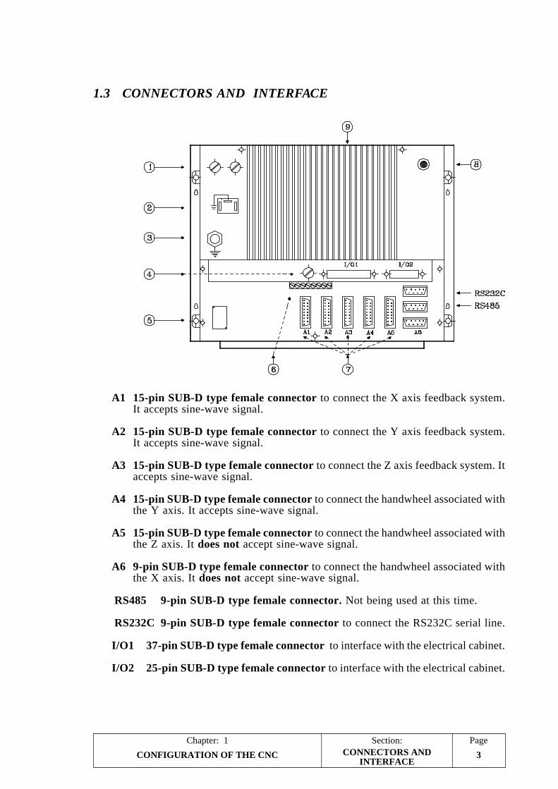
1.3 CONNECTORS AND INTERFACE
A1 15-pin SUB-D type female connector to connect the X axis feedback system.It accepts sine-wave signal.
A2 15-pin SUB-D type female connector to connect the Y axis feedback system.It accepts sine-wave signal.
A3 15-pin SUB-D type female connector to connect the Z axis feedback system. Itaccepts sine-wave signal.
A4 15-pin SUB-D type female connector to connect the handwheel associated withthe Y axis. It accepts sine-wave signal.
A5 15-pin SUB-D type female connector to connect the handwheel associated withthe Z axis. It does not accept sine-wave signal.
A6 9-pin SUB-D type female connector to connect the handwheel associated withthe X axis. It does not accept sine-wave signal.
RS485 9-pin SUB-D type female connector. Not being used at this time.
RS232C 9-pin SUB-D type female connector to connect the RS232C serial line.
I/O1 37-pin SUB-D type female connector to interface with the electrical cabinet.
I/O2 25-pin SUB-D type female connector to interface with the electrical cabinet.

Section:Chapter: 1Page
CONFIGURATION OF THE CNC4
1- Main AC fuse. It has two 3.15Amp./250V. fast fuses (F), one per AC line, toprotect the main AC input.
2- AC power connector To power the CNC. It must be connected to the powertransformer and to ground.
3- Ground terminal. It must be connected to the general machine ground point.Metric 6.
4- Fuse. 3.15Amp./250V fast fuse (F) to protect the internal I/O circuitry of theCNC.
5- Lithium battery. Maintains the RAM data when the system's power disappears.
6- Adjustment potentiometers for the analog outputs. ONLY TO BE USED BYTHE TECHNICAL SERVICE DEPARTMENT.
7- 10 dip-switches. There are 2 under each feedback connector (A1 thru A5) andthey are utilized to set the CNC according to the type of feedback signal beingused.
8 CRT brightness adjustment potentiometer
9 Heat-sink.
Atention:
Do not manipulate the connectors with the unit connected to main ACpower
Before manipulating these connectors (inputs/outputs, feedbach, etc)make sure that the unit is not connected to main AC power
CONNECTORS ANDINTERFACE

PageChapter: 1 Section:
CONFIGURATION OF THE CNC 5
1.3.1 CONNECTORS A1, A2, A3, A4
They are 15-pin SUB-D type female connectors used to connect the feedback signals.
* Connector A1 for X axis feedback signals.* Connector A2 for Y axis feedback signals.* Connector A3 for Z axis feedback signals.* Connector A4 for Y axis electronic handwheel feedback signals.
The cable must have overall shield. The rest of the specifications depend on thefeedback system utilized and the cable length required.
It is highly recommended to run these cables as far as possible from the power cablesof the machine.
PIN SIGNAL AND FUNCTION
1 A2 A Differential square-wave feedback signals3 B4 B
5 Io Machine Reference Signals (marker pulses)6 Io
7 Ac Sine-wave feedback signals8 Bc
9 +5V. Power to feedback system.10 Not connected.11 0V. Power to feedback system.12 Not connected.13 -5V. Power to feedback system.14 Not connected.
15 CHASSIS Shield
Atention:
When using square-wave rotary encoders, their signals must be TTLcompatible. Encoders with open collector outputs MUST NOT be used.
Do not manipulate the connectors with the unit connected to main ACpower
Before manipulating these connectors (inputs/outputs, feedbach, etc)make sure that the unit is not connected to main AC power
CONNECTORSA1, A2, A3 & A4

Section:Chapter: 1Page
CONFIGURATION OF THE CNC6
1.3.1.1 DIP-SWITCHES FOR CONNECTORS A1, A2, A3, A4
There are 2 dip-switches below each feedback input connector (A1 thru A4) to setthe CNC according to the type of feedback signal being used.
Switch 1 indicates whether the feedback signal is sine-wave or square-wave andswitch 2 indicates whether the feedback signal is single- or double-ended (differential).
The possible types of feedback signals to be used at connectors A1 thru A4 are:
* Sine-wave (Ac, Bc, Io)* Single-ended square-wave (A, B, Io)* Double-ended (differential) square-wave (A, A, B, B, Io, Io)
To select the type of signal for each axis, use the switch combinations below:
Dip-switch SIGNAL AND FUNCTION1 2
ON ON Single-ended sine-wave signal (Ac,Bc,Io)ON OFF Double-ended sine-wave signal "Not allowed"OFF ON Single-ended square-wave signal (A,B,Io)OFF OFF Double-ended square-wave (A, A, B, B, Io, Io)
There is a label next to each dip-switch pair indicating the meaning of each switch.
CONNECTORSA1, A2, A3 & A4

PageChapter: 1 Section:
CONFIGURATION OF THE CNC 7
1.3.2 CONNECTOR A5
It is a 15-pin SUB-D type female connector to connect the electronic handwheel tothe Z axis. It does not accept sine-wave signals.
When using the spindle encoder and an electronic handwheel, the CNC will onlycontrol up to 4 axes. This connector will then be used for the spindle encoder or theelectronic handwheel (the other device will be connected to A6).
The cable must have overall shield. The rest of the specifications depend on thefeedback system utilized and the cable length required.
It is highly recommended to run these cables as far as possible from the power cablesof the machine.
PIN SIGNAL AND FUNCTION
1 A2 A Double-ended square-wave signal.3 B4 B
5 Not being used at this time6 Not being used at this time
7 Not being used at this time8 Not being used at this time
9 +5V. Power to feedback system.10 Not connected.11 0V. Power to feedback system.12 Not connected.13 -5V. Power to feedback system.14 Not connected.
15 CHASSIS Shield.
Atention:
When the handwheel outputs square-wave signals, they must be TTLcompatible. Handwheel with open collector outputs MUST NOT be used.
Do not manipulate the connectors with the unit connected to main ACpower
Before manipulating these connectors (inputs/outputs, feedbach, etc)make sure that the unit is not connected to main AC power
CONNECTOR A5

Section:Chapter: 1Page
CONFIGURATION OF THE CNC8
1.3.2.1 DIP-SWITCHES FOR CONNECTOR A5
There are 2 dip-switches below this feedback input connector to set the CNC accordingto the type of feedback signal being used.
Switch 1 indicates whether the feedback signal is sine-wave or square-wave andswitch 2 indicates whether the feedback signal is single- or double-ended (differential).
The possible types of feedback signals to be used at connector A5 are:
* Single-ended square-wave (A, B, Io)* Double-ended (differential) square-wave (A, A, B, B, Io, Io)
To select the type of signal for each axis, use the switch combinations below:
Dip-switch SIGNAL AND FUNCTION1 2
ON ON Single-ended sine-wave signal "Not allowed"ON OFF Double-ended sine-wave signal "Not allowed"OFF ON Single-ended square-wave signal (A,B,Io)OFF OFF Double-ended square-wave (A, A, B, B, Io, Io)
There is a label next to each dip-switch pair indicating the meaning of each switch.
CONNECTOR A5

PageChapter: 1 Section:
CONFIGURATION OF THE CNC 9
1.3.3 CONNECTOR A6
It is a 9-pin SUB-D type female connector to connect the electronic handwheelassociated with the X axis. It does not take sine-wave signals.
The cable must have overall shield. The rest of the specifications depend on thefeedback system utilized and the cable length required.
It is highly recommended to run these cables as far away as possible from the powercables of the machine.
PIN SIGNAL AND FUNCTION
1 A Square-wave signals from the spindle2 B encoder or from the electronic handwheel
3 Axis selector signal (FAGOR 100P)
4 +5V Supply voltage for electronic handwheel5 0V
6 Not being used at this time7 Not being used at this time8 Not being used at this time
9 CHASSIS Shield.
Atention:
When the handwheel outputs square-wave signals, they must be TTLcompatible. Handwheel with open collector outputs MUST NOT be used.
When using the FAGOR 100P handwheel, the axis selector signal mustbe connected to pin 3.
Do not manipulate the connectors with the unit connected to main ACpower
Before manipulating these connectors (inputs/outputs, feedbach, etc)make sure that the unit is not connected to main AC power
CONNECTOR A6

Section:Chapter: 1Page
CONFIGURATION OF THE CNC10
1.3.4 RS232C CONNECTOR
9-pin SUB-D type female connector to connect the RS 232 C serial port.
The cable shield must be soldered to pin 1 at the CNC end and to the metallic housingat the peripheral end.
PIN SIGNAL FUNCTION
1 FG Shield2 TxD Transmit Data3 RxD Receive Data4 RTS Request To Send5 CTS Clear To Send6 DSR Data Send Ready7 GND Ground8 —- Not connected9 DTR Data Terminal Ready
SUGGESTIONS FOR THE RS232C INTERFACE
* Connect/disconnect peripheral. The CNC must be powered off when connectingor disconnecting any peripheral through this connector.
* Cable length. EIA RS232C standards specify that the capacitance of the cablemust not exceed 2500pF; therefore, since average cables have a capacitancebetween 130pF and 170pF per meter, the maximum length of the cable shouldnot be greater than 15m (49ft).
For greater distances, it is suggested to intercalate RS232C-to-RS422A signalconverters (and vice-versa). Contact the corresponding distributor.
Shielded cable with twisted-pair wires should be used to avoid communicationinterference when using long cables.
Use shielded 7-conductor cable of 7*0.14mm² section.
* Transmission speed (baudrate). The baudrate normally used with peripheralsis 9600 baud.
All unused wires should be grounded to avoid erroneous control and data signals.
* Ground connection. It is suggested to reference all control and data signals tothe same ground cable (pin 7 GND) thus, avoiding reference points at differentvoltages especially in long cables.
RS232C CONNECTOR

PageChapter: 1 Section:
CONFIGURATION OF THE CNC 11
RECOMMENDED CONNECTIONS FOR THE RS232C INTERFACE
* Complete connection
* Simplified connection
To be used when the peripheral or the computer meets one of the followingrequirements:- It does not have the RTS signal.- It is connected via DNC.- The receiver can receive data at the selected baudrate.
Nevertheless, it is suggested to refer to the technical manuals of the peripheralequipment in case there should be any discrepancy.
RS232C CONNECTOR

Section:Chapter: 1Page
CONFIGURATION OF THE CNC12 RS232C CONNECTOR

PageChapter: 1 Section:
CONFIGURATION OF THE CNC 13CONNECTOR I/O1
1.3.5 CONNECTOR I/O 1
It is a 37-pin SUB-D type female connector to interface with the electrical cabinet.
Pin SIGNAL AND FUNCTION
1 0V. Input from external power supply2 T Strobe Output. The BCD outputs represent a tool code.3 S Strobe Output. The BCD outputs represent a spindle speed code.4 M Strobe Output. The BCD outputs represent an M code.5 Emergency Output.6 Not being used at this time.
7 Z Enable Output.8 Y Enable Output.9 X Enable Output.10 X home switch Input from machine reference switch.11 Y home switch Input from machine reference switch.12 Z home switch Input from machine reference switch.13 Not being used at this time.14 Emergency Stop Input.15 Feed Hold Input.
Transfer inhibitM-done
16 Stop Input.
17 Start InputRapid JOG
18 Block Skip Conditional Input19 DRO Input. The CNC acts as a DRO20 MST80 BCD coded output, weight: 8021 MST40 BCD coded output, weight: 4022 MST20 BCD coded output, weight: 2023 MST10 BCD coded output, weight: 1024 MST08 BCD coded output, weight: 825 MST04 BCD coded output, weight: 426 MST02 BCD coded output, weight: 227 MST01 BCD coded output, weight: 128 CHASSIS Connect all cable shields to this pin.29 24V. Input from external power supply.30 ±10V Analog output for X axis servo drive.31 0V. Analog output for X axis servo drive.32 ±10V Analog output for Y axis servo drive.33 0V. Analog output for Y axis servo drive.34 ±10V Analog output for Z axis servo drive.35 0V. Analog output for Z axis servo drive.36 ±10V Analog output for the spindle drive.37 0V. Analog output for the spindle drive.
Atention:
The machine manufacturer must comply with the EN 60204-1 (IEC-204-1) regulationregarding the protection against electrical shock derived from defective input/outputconnection with the external power supply when this connector is not connected beforeturning the power supply on.
Do not manipulate the connectors with the unit connected to main AC powerBefore manipulating these connectors (inputs/outputs, feedbach, etc) makesure that the unit is not connected to main AC power

Section:Chapter: 1Page
CONFIGURATION OF THE CNC14
1.3.5.1 INPUTS OF CONNECTOR I/O 1
0 V. Pin 1
INPUT from external power supply.
X AXIS HOME SWITCH Pin 10
This INPUT must be high (24V) as long as the machine reference switch for theX axis is pressed.
Y AXIS HOME SWITCH Pin 11
This INPUT must be high (24V) as long as the machine reference switch for theY axis is pressed.
Z AXIS HOME SWITCH Pin 12
This INPUT must be high (24V) as long as the machine reference switch for theZ axis is pressed.
EMERGENCY STOP Pin 14
This INPUT must be normally high (24V).
When set low (0V), the CNC deactivates the axis enables and analog voltages,it interrupts the part program execution and it displays ERROR 64 on the CRT.
It does not imply an emergency output (pin 5 of this connector).
FEED HOLD / TRANSFER INHIBIT / M-DONE Pin 15
This INPUT must be normally high (24V) and its meaning depends on the typeof block or function being executed at the time.
* If while moving the axes this signal (FEED-HOLD) is set low (0V), the CNCmaintains the spindle turning and stops the axes bringing their analog voltagesto 0V while maintaining their enables active.
When this input is brought back high (24V), the axes will resume theirmovements.
* If while executing a motionless block this signal (TRANSFER INHIBIT) isset low (0V), the CNC interrupts the program execution at the end of the blockcurrently in execution.
When this signal is brought back high, the CNC resumes program execution.
* The "M-DONE" signal is used when machine parameter P605(5) is set to "1".
The CNC waits for the electrical cabinet to execute the requested miscellaneousM function. In other words, it waits for the "M-done" input to be set high(24V).
CONNECTOR I/O1(inputs)
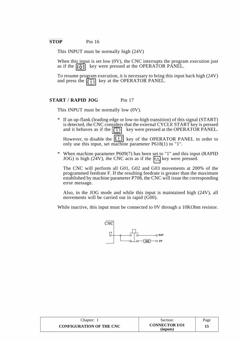
PageChapter: 1 Section:
CONFIGURATION OF THE CNC 15
STOP Pin 16
This INPUT must be normally high (24V)
When this input is set low (0V), the CNC interrupts the program execution justas if the key were pressed at the OPERATOR PANEL.
To resume program execution, it is necessary to bring this input back high (24V)and press the key at the OPERATOR PANEL.
START / RAPID JOG Pin 17
This INPUT must be normally low (0V).
* If an up-flank (leading edge or low-to-high transition) of this signal (START)is detected, the CNC considers that the external CYCLE START key is pressedand it behaves as if the key were pressed at the OPERATOR PANEL.
However, to disable the key of the OPERATOR PANEL in order toonly use this input, set machine parameter P618(1) to "1".
* When machine parameter P609(7) has been set to "1" and this input (RAPIDJOG) is high (24V), the CNC acts as if the key were pressed.
The CNC will perform all G01, G02 and G03 movements at 200% of theprogrammed feedrate F. If the resulting feedrate is greater than the maximumestablished by machine parameter P708, the CNC will issue the correspondingerror message.
Also, in the JOG mode and while this input is maintained high (24V), allmovements will be carried out in rapid (G00).
While inactive, this input must be connected to 0V through a 10KOhm resistor.
CONNECTOR I/O1(inputs)

Section:Chapter: 1Page
CONFIGURATION OF THE CNC16
BLOCK SKIP (Conditional input) Pin 18
Every time the CNC executes the miscellaneous function M01 (conditional stop),it analyzes the status of this input. If high (24V), the CNC will interrupt theexecution of the program.
By the same token, every time the CNC must execute a conditional block, it willanalyze the status of this input and it will execute the block if this input is high(24V).
DRO (DRO mode) Pin 19
If this input is set high (24V) while in the JOG mode, the CNC acts as a DRO.
CONNECTOR I/O1(inputs)
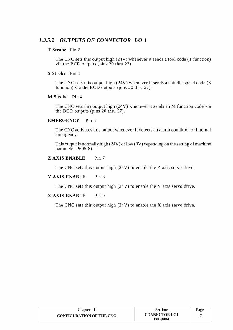
PageChapter: 1 Section:
CONFIGURATION OF THE CNC 17
1.3.5.2 OUTPUTS OF CONNECTOR I/O 1
T Strobe Pin 2
The CNC sets this output high (24V) whenever it sends a tool code (T function)via the BCD outputs (pins 20 thru 27).
S Strobe Pin 3
The CNC sets this output high (24V) whenever it sends a spindle speed code (Sfunction) via the BCD outputs (pins 20 thru 27).
M Strobe Pin 4
The CNC sets this output high (24V) whenever it sends an M function code viathe BCD outputs (pins 20 thru 27).
EMERGENCY Pin 5
The CNC activates this output whenever it detects an alarm condition or internalemergency.
This output is normally high (24V) or low (0V) depending on the setting of machineparameter P605(8).
Z AXIS ENABLE Pin 7
The CNC sets this output high (24V) to enable the Z axis servo drive.
Y AXIS ENABLE Pin 8
The CNC sets this output high (24V) to enable the Y axis servo drive.
X AXIS ENABLE Pin 9
The CNC sets this output high (24V) to enable the X axis servo drive.
CONNECTOR I/O1(outputs)

Section:Chapter: 1Page
CONFIGURATION OF THE CNC18
MST80 Pin 20MST40 Pin 21MST20 Pin 22MST10 Pin 23MST08 Pin 24MST04 Pin 25MST02 Pin 26MST01 Pin 27
The CNC uses these outputs to indicate to the electrical cabinet the M, S or Tfunction that has been selected.
This information is BCD coded and the significance (weight) of each output isexpressed by the corresponding mnemonic.
For example, to select the first spindle speed range, the CNC sends the M41code out to the electrical cabinet.
MST80 MST40 MST20 MST10 MST08 MST04 MST02 MST010 1 0 0 0 0 0 1
Together with these signals, the CNC will activate the "M Strobe", "T Strobe"or "S Strobe" output to indicate the type of function being selected.
CHASSIS Pin 28
This pin must be used to connect all cable shields to it.
Analog voltage for X ±10V. Pin 30Analog voltage for X 0V. Pin 31
These outputs provide the analog voltage for the X axis servo drive. The cableused for this connection must be shielded.
Analog voltage for Y ±10V. Pin 32Analog voltage for Y 0V. Pin 33
These outputs provide the analog voltage for the Y axis servo drive. The cableused for this connection must be shielded.
Analog voltage for Z ±10V. Pin 34Analog voltage for Z 0V. Pin 35
These outputs provide the analog voltage for the Z axis servo drive. The cableused for this connection must be shielded.
Spindle analog voltage ±10V. Pin 36Spindle analog voltage 0V. Pin 37
These outputs provide the analog voltage for the spindle drive. The cable usedfor this connection must be shielded.
CONNECTOR I/O1(outputs)

PageChapter: 1 Section:
CONFIGURATION OF THE CNC 19
1.3.6 CONNECTOR I/O 2
It is a 25-pin SUB-D type female connector to interface with the electrical cabinet.
PIN SIGNAL AND FUNCTION
1 0V. Input from external power supply.2 0V. Input from external power supply.3 Output M1 Value of bit 1 of the decoded M function table.
Coolant4 Output M2 Value of bit 2 of the decoded M function table.5 Output M3 Value of bit 3 of the decoded M function table.6 Output M4 Value of bit 4 of the decoded M function table.7 Output M5 Value of bit 5 of the decoded M function table.8 Output M6 Value of bit 6 of the decoded M function table.9 Output M7 Value of bit 7 of the decoded M function table.10 Output M8 Value of bit 8 of the decoded M function table.11 Output M9 Value of bit 9 of the decoded M function table.12 Output M10 Value of bit 10 of the decoded M function table.
Mandatory Io13 Output M11 Value of bit 11 of the decoded M function table.14 Not being used at this time15 Not being used at this time16 CHASSIS Connect all cable shields to this pin.17 Not being used at this time18 Not being used at this time19 24V. Input from external power supply.20 24V. Input from external power supply.21 JOG Output. JOG mode is selected.22 Output M15 Value of bit 15 of the decoded M function table.23 Output M14 Value of bit 14 of the decoded M function table.
Reset24 Output M13 Value of bit 13 of the decoded M function table.
Indicates that a program block is being executed.Indicates that program P99996 is being executed.Indicates that the axes are being positioned in rapid.
25 Output M12 Value of bit 12 of the decoded M function table.Vertical axis
Atention:
The machine manufacturer must comply with the EN 60204-1 (IEC-204-1) regulationregarding the protection against electrical shock derived from defective input/outputconnection with the external power supply when this connector is not connectedbefore turning the power supply on.
Do not manipulate the connectors with the unit connected to main AC powerBefore manipulating these connectors (inputs/outputs, feedbach, etc) makesure that the unit is not connected to main AC power
CONNECTOR I/O2

Section:Chapter: 1Page
CONFIGURATION OF THE CNC20
1.3.6.1 OUTPUTS OF CONNECTOR I/O 2
"Decoded M" outputs Pins 3, 4, 5, 6, 7, 8, 9, 10, 11, 12, 13, 22, 23, 24, 25
These OUTPUTS provide the values indicated at the table corresponding to theselected M function.
For example: If the table corresponding to function M41 has been set as follows:
M41 100100100100100 (outputs to be activated)00100100100100100 (outputs to be deactivated)
Every time this M41 function is executed, the CNC will act as follows:
Outputs M01 / Coolant Pin 3
This output, besides providing the value of bit 1 of the decoded table correspondingto the selected M function, acts as the output for the coolant.
When using it as the coolant output, be careful not to set the bit of the decodedM table which corresponds to this M1 output since the CNC will activate it inboth cases.
Nevertheless, the CNC maintains this output active whenever the coolant is activeeven when executing an M function which would deactivate it.
Outputs M10 / Mandatory Io Pin 12
This output provides the value of bit 10 of the decoded table corresponding tothe selected M function.
If machine parameter P611(2) has been set to "1", the CNC sets this output highon power-up and keeps it high until all the axes are referenced (homed).
Care must be taken when using this option not use the bit of the decoded M tablecorresponding to this output M10 since the CNC will activate it in both cases.
CONNECTOR I/O2
M01 M02 M03 M04 M05 M06 M07 M08 M09 M10 M11 M12 M13 M14 M15
Pin I/O2 3 4 5 6 7 8 9 10 11 12 13 25 24 23 22
at 24V x x x x x
at 0V x x x x x
Notmodified
x x x x x

PageChapter: 1 Section:
CONFIGURATION OF THE CNC 21
JOG Pin 21
The CNC sets this OUTPUT high (24V) whenever the JOG mode is selected.
Outputs M14 / RESET Pin 23
This OUTPUT provides the value of bit 14 of the decoded M table correspondingto the selected M function.
If machine parameter P609(3) is set to "1" to provide a RESET pulse, this positivereset pulse will be output every time the CNC executes a RESET.
Care must be taken, when having this option, not to use the bit of the decodedM table corresponding to this output M14 since the CNC will activate it in bothcases.
Outputs M13 / Program block in execution / P99996 in execution /Rapid positioning in progress Pin 24
This OUTPUT provides the value of bit 13 of the decoded M table correspondingto the selected M function.
If machine parameter P611(1) is set to "1", the CNC sets this OUTPUT high(24V) every time a part-program block is being executed.
If machine parameter P611(6) is set to "1", the CNC sets this OUTPUT high(24V) whenever the special ISO-coded user program P99996 is being executed.
If machine parameter P613(4) is set to "1", the CNC sets this OUTPUT high(24V) whenever the CNC is executing a rapid positioning move
Care must be taken, when having one of these options, not to use the bit of thedecoded M table corresponding to this output M13 since the CNC will activateit in all these cases.
Outputs M12 / Vertical axis movement Pin 25
This OUTPUT provides the value of bit 12 of the decoded M table correspondingto the selected M function.
If machine parameter P613(2) is set to "1" in order for the CNC to provide thestatus of the vertical axis movement, this output will indicate the direction ofthat movement. If the axis is moving in the positive direction (counting up), thisoutput will be set low (0V) and it will be set high (24V) if moving in the negativedirection (counting down).
Care must be taken, when having this option, not to use the bit of the decodedM table corresponding to this output M12 since the CNC will activate it in bothcases.
CONNECTOR I/O2

PageChapter: 2 Section:
POWER AND MACHINE INTERFACE 1
2. POWER AND MACHINE INTERFACE
Atention:
Power switchThis power switch must be mounted in such a way that it is esailyaccessed and at a distance between 0.7 meters (27.5 inches) and 1.7meters (5.5 ft) off the floor.
Intall this unit in the proper placeIt is recommended to install the CNC away from coolants, chemicalproducts, possible blows etc. which could damage it.
2.1 POWER INTERFACE
The rear of the 800M CNC has a three-prong connector for AC and ground connection.
This connection must be done through an independent shielded 110VA transformerwith an AC output voltage between 100V and 240V +10% -15%.
The power outlet for the equipment must be near it and with easy access to it.
In case of overload or overvoltage, it is recommended to wait for 3 minutes beforepowering the unit back up in order to prevent any possible damage to the powersupply.
2.1.1 INTERNAL POWER SUPPLY
Inside the 800M CNC there is a power supply providing the required voltages.
Besides the 2 outside AC power fuses (one per line), it has a 5 Amp. fuse inside toprotect it against overcurrent.
POWER INTERFACE

Section:Chapter: 2Page
POWER AND MACHINE INTERFACE2
2.2 MACHINE INTERFACE
2.2.1 GENERAL CONSIDERATIONS
The machine tool must have decoupled all those elements capable of generatinginterference (relay coils, contactors, motors, etc.).
* D.C. Relay coils.
Diode type 1N4000.
* A.C. relay coils
RC connected as close as possible to the coils. Their approximate values shouldbe:
R 220 Ohms/1WC 0,2 µF/600V
* A.C. motors.
RC connected between phases with values:
R 300 Ohms/6WC 0,47µF/600V
Ground connection.
It is imperative to carry out a proper ground connection in order to achieve:
* Protection of anybody against electrical shocks caused by a malfunction.
* Protection of the electronic equipment against interference generated by theproper machine or by other electronic equipment near by which could causeerratic equipment behavior.
Therefore, it is crucial to install one or two ground points where the abovementioned elements must be connected.
Use large section cables for this purpose in order to obtain low impedance andefficiently avoid any interference. This way, all parts of the installation will havethe same voltage reference.
Even when a proper ground connection reduces the effects of electricalinterference (noise), the signal cables require additional protection.This is generally achieved by using twisted-pair cables which are also coveredwith anti-static shielding mesh-wire. This shield must be connected to a specificpoint avoiding ground loops that could cause undesired effects. This connectionis usually done at one of the CNC's ground points.
MACHINE INTERFACE

PageChapter: 2 Section:
POWER AND MACHINE INTERFACE 3
Each element of the machine-tool/CNC interface must be connected to groundvia the established main points. These points will be conveniently set close tothe machine-tool and properly connected to the general ground (of the building).
When a second point is necessary, it is recommended to join both points with acable whose section is not smaller than 8 mm².
Verify that the impedance between the central point of each connector housingand the main ground point is less than 1 Ohm.
Ground connection diagram
MACHINE INTERFACE
Chassis
Ground
Ground (for safety)

Section:Chapter: 2Page
POWER AND MACHINE INTERFACE4
2.2.2 DIGITAL OUTPUTS.
The CNC has several optocoupled digital outputs which may be used to activaterelays, deacons, etc.
These digital outputs, with galvanic isolation by optocouplers, can commutate D.C.voltages supplied by the electrical cabinet of the machine.
The electrical characteristics of these outputs are:
Nominal voltage value +24 V D.C.Maximum voltage value +30 V D.C.Minimum voltage value +18 V D.C.Output voltage Vcc.- 2VMaximum output current 100 mA.
All outputs are protected by means of:
Galvanic isolation by optocouplers.External 3A fuse for protection against output overload (greater than 125mA),external power supply overvoltage (over 33V DC) and against reverse connectionof the external power supply.
2.2.3 DIGITAL INPUTS.
The digital inputs of the CNC are to used to "read" external devices.
All of them are galvanically isolated from the outside world by optocouplers.
The electrical characteristics of these inputs are:
Nominal voltage value +24 V DCMaximum voltage value +30 V.Minimum voltage value +18 V.High threshold voltage (logic state 1) over +18V.Low threshold voltage (logic state 0) under +5V.Typical input consumption 5 mA.Maximum consumption per input 7 mA.
All inputs are protected by means of:
Galvanic isolation by optocouplers.Protection against reverse connection of the power supply up to -30V.
Atention:
The external 24V power supply used for the digital inputs and outputsmust be regulated.
The 0V point of this power supply must be connected to the main groundpoint of the electrical cabinet.
DIGITAL INPUTS/OUTPUTS

PageChapter: 2 Section:
POWER AND MACHINE INTERFACE 5
2.2.4 ANALOG OUTPUTS.
The CNC has 6 analog outputs which could be used to command servo drives, spindledrives and other devices.
The electrical characteristics of these outputs are:
Analog voltage range: ±10V.Minimum impedance of the connected drive: 10 KOhm.Maximum cable length without shield: 75 mm.
It is highly recommended to use the shielded cable connecting the shield to thecorresponding pin of the connector.
Atention:
It is recommended to adjust the servo drives so their maximum feedrate(G00) is obtained at ±9.5 V.
2.2.5 FEEDBACK INPUTS
The feedback inputs are used to receive sine-wave, single-ended and double-endedsquare-wave signals coming from linear or rotary transducers (encoders).
Connector A1 is used for the X axis feedback signals and it accepts sine-wave anddouble-ended (differential) square-wave signals.
Connector A2 is used for the Y axis feedback signals and it accepts sine-wave anddouble-ended (differential) square-wave signals.
Connector A3 is used for the Z axis feedback signals and it accepts sine-wave anddouble-ended (differential) square-wave signals.
Connector A4 is used for the handwheel associated to the Y axis and it accepts sine-wave and double-ended (differential) square-wave signals.
Connector A5 is used for the handwheel associated to the Z axis and it accepts double-ended (differential) square-wave signals.
Connector A6 is used for the handwheel associated to the X axis and it accepts single-ended (not differential) square-wave signals.
The electrical characteristics of these inputs are:
Sine-wave signals Supply voltage ±5V.±5%Maximum counting frequency 25KHz.
Square-wave signals Supply voltage ±5V.±5%Maximum counting frequency 200KHz.
It is recommended to use shielded cables for their connection connecting the shieldto the corresponding pin of the connector.
ANALOG OUTPUTSFEEDBACK INPUTS

Section:Chapter: 2Page
POWER AND MACHINE INTERFACE6
2.3 SET-UP
2.3.1 GENERAL CONSIDERATIONS
Inspect the whole electrical cabinet verifying the ground connections BEFOREpowering it up.
This ground connection must be done at a single machine point (Main Ground Point)and all other ground points must be connected to this point.
Verify that the 24V external power supply used for the digital inputs and outputs isREGULATED and that its 0V are connected to the Main Ground Point.
Verify the connection of the feedback system cables to the CNC.
DO NOT connect or disconnect these cables to/from the CNC when the CNC is on.
Look for short-circuits in all connectors (inputs, outputs, axes, feedback, etc.) BEFOREsupplying power to them.
2.3.2 PRECAUTIONS
It is recommended to reduce the axis travel installing the limit switches closer toeach other or detaching the motor from the axis until they are under control.
Verify that there is no power going from the servo drives to the motors.
Verify that the connectors for the digital inputs and outputs are disconnected.
Verify that the feedback dip-switches for each axis are set according to the type offeedback signal being used.
Verify that the E-STOP button is pressed.
SET-UP

PageChapter: 2 Section:
POWER AND MACHINE INTERFACE 7
2.3.3 CONNECTION
Verify that the AC power is correct.
Being the CNC disconnected, power the electrical cabinet and verify that it respondsproperly.
Verify that there is proper voltage between the pins corresponding to 0V and 24Vof the connectors for the digital inputs and outputs.
Apply 24V to each one of the terminals of the electrical cabinet being used thatcorrespond to the digital outputs of the CNC and verify their correct performance.
With the motors being decoupled from the axes, verify that the system consisting ofdrive, motor and tacho is operating properly.
Connect the AC power to the CNC. After a self-test, the CNC will show the message:"GENERAL TEST PASSED". If there is any problem, the CNC will display thecorresponding error message.
SET-UP

Section:Chapter: 2Page
POWER AND MACHINE INTERFACE8
2.3.4 SYSTEM INPUT/OUTPUT TEST
This CNC offers a work mode which allows the possibility to activate or deactivateeach one of the logic inputs and outputs of the CNC.
To do this, press the following keystroke sequence:
[AUX] (SPECIAL FUNCTIONS)[5] (AUXILIARY MODES)[1] (SPECIAL MODES)[0] [1] [0] [1] (Access code) (password)[0] (TEST)
Once the CNC has performed the system self-test, press [7] and the CNC will showthe status of the logic inputs being possible to change the status of the logic outputs.
Logic inputs
INPUT PIN FUNCTION
A 17 (I/O 1) STARTB 16 (I/O 1) STOPC 15 (I/O 1) FEEDHOLDD 14 (I/O 1) EMERGENCY STOPE To be used only by the technical serviceF 12 (I/O 1) Z axis home switchG 11 (I/O 1) Y axis home switchH 10 (I/O 1) X axis home switchI 19 (I/O 1) DRO modeJ 18 (I/O 1) Block skip (conditional stop)K To be used only by the technical serviceL To be used only by the technical serviceM To be used only by the technical serviceN To be used only by the technical service
The CNC will show at all times and dynamically the status of all these inputs.To check a specific one, just actuate on the external push-button or switchobserving its behavior on the CRT.
The value of "1" on the screen indicates that the corresponding input is receiving24V DC and a "0" indicates that it doesn't.
SET-UP

PageChapter: 2 Section:
POWER AND MACHINE INTERFACE 9
Logic outputs
ROW 1 ROW 2OUTPUT PIN/FUNCTION PIN/FUNCTION
A (2 I/O 1) T Strobe (3 I/O 2) Output 1, decoded MB (3 I/O 1) S Strobe (4 I/O 2) Output 2, decoded MD (5 I/O 1) Emergency (6 I/O 2) Output 4, decoded ME (6 I/O 1) Threading ON (7 I/O 2) Output 5, decoded MF (7 I/O 1) Z Enable (8 I/O 2) Output 6, decoded MG (8 I/O 1) Y Enable (9 I/O 2) Output 7, decoded MH (9 I/O 1) X Enable (10 I/O 2) Output 8, decoded MI (27 I/O 1) MST01 (11 I/O 2) Output 9, decoded MJ (26 I/O 1) MST02 (12 I/O 2) Output 10, decoded MK (25 I/O 1) MST04 (13 I/O 2) Output 11, decoded ML (24 I/O 1) MST08 (25 I/O 2) Output 12, decoded MM (23 I/O 1) MST10 (24 I/O 2) Output 13, decoded MN (22 I/O 1) MST20 (23 I/O 2) Output 14, decoded MO (21 I/O 1) MST40 (22 I/O 2) Output 15, decoded MP (20 I/O 1) MST80 (21 I/O 2) CNC in JOG mode
To check one of these outputs, select it with the cursor which may be moved bymeans of the right and left arrow keys.
Once the desired output is selected, press "1" to activate it and "0" to deactivateit. The CRT will show the status change.
It is possible to have several outputs active at the same time providing 24V attheir corresponding pins.
Once the INPUT/OUTPUT test is completed, disconnect the electrical cabinet and,then, connect the input/output connectors as well as the feedback systems of theaxes to the CNC.
Then, connect the electrical cabinet and the CNC to AC power and activate the servodrives.
Nevertheless, to quit the I/O testing mode, press [END].
SET-UP

Section:Chapter: 2Page
POWER AND MACHINE INTERFACE10
2.4 EMERGENCY INPUT/OUTPUT CONNECTION
The Emergency Input of the CNC is called EMERGENCY STOP (E-STOP) andcorresponds to pin 14 of connector I/O1. This input must normally have 24V DC.
The CNC processes this signal directly, therefore, whenever these 24V disappear, itwill issue EXTERNAL EMERGENCY ERROR (Error 64), it will deactivate theaxes enables and cancel the analog voltages for all the axes and the spindle.It does NOT imply the emergency output (pin5).
The electrical cabinet interface must take into account all the external elements thatcould cause this error.
For example, some of these elements may be:
* The E-Stop button has been pressed.
* An axis travel limit switch has been pressed.
* An axis servo drive is not ready.
On the other hand, whenever a CNC detects an internal emergency error, it willactivate the EMERGENCY OUTPUT at pin 5 of connector I/O1.
This output will be normally high or low depending on the setting of machine parameterP605(8).
There are some of the internal causes that can activate this output:
* An excessive axis following error has occurred.
* An axis feedback error has occurred.
* There is erroneous data on the machine parameter table.
EMERGENCY I/OCONNECTION
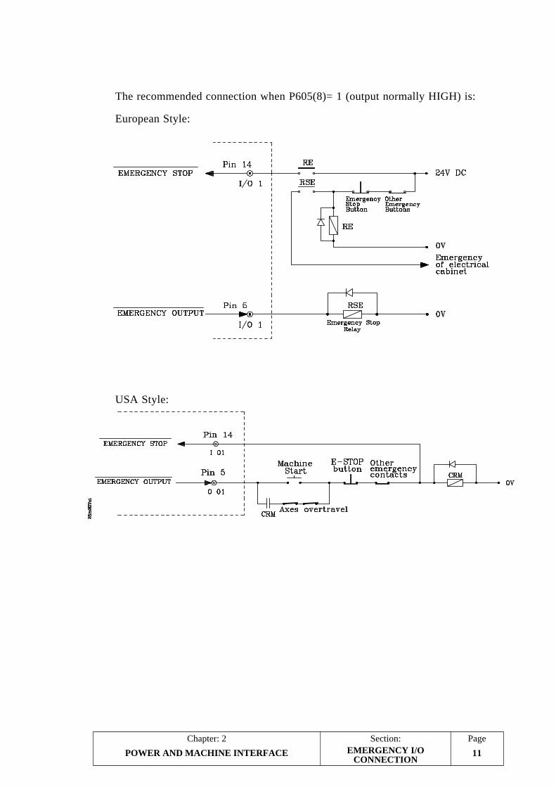
PageChapter: 2 Section:
POWER AND MACHINE INTERFACE 11
The recommended connection when P605(8)= 1 (output normally HIGH) is:
European Style:
USA Style:
EMERGENCY I/OCONNECTION

Section:Chapter: 2Page
POWER AND MACHINE INTERFACE12
The recommended connection when P605(8)= 0 (output normally LOW) is:
European Style:
USA Style:
EMERGENCY I/OCONNECTION

PageChapter: 2 Section:
POWER AND MACHINE INTERFACE 13EXTERNAL DEVICESON/OFF
2.5 ACTIVATION / DEACTIVATION OF EXTERNAL DEVICES
With this CNC it is possible to activate and deactivate up to 4 external devices includingthe coolant. The other devices depend on the type of machine available.
To do this, the following keys are available:
If it is selected (lamp on); pin 3 of connector I/O2 stays high (24V).
When it is not selected, (lamp off); pin 3 of connector I/O2 stays low (0V)
When this device (O1) is selected, the CNC sends the M10 function out toactivate it and an M11 to deactivate it.
When this device (O2) is selected, the CNC sends the M12 function out toactivate it and an M13 to deactivate it.
When this device (O3) is selected, the CNC sends the M14 function out toactivate it and an M15 to deactivate it.
The coolant may be activated or deactivated at any time but the other devices (O1,O2 and O3) must be activated or deactivated only when the axes of the machine arein position.

PageChapter: 3 Section:
1AUXILIARY FUNCTIONS
3. AUXILIARY FUNCTIONS
Press [AUX] to access this option.
The CNC will show a series of options. To select one of them, simply press thenumber key indicated for the desired option.
The operator may access all the shown options except the one referred to as"AUXILIARY MODES". When selecting this option, the CNC requests the passwordto access the various tables and operating modes exclusive for the OEM.
Press [END] to quit any of these options and return to the standard display mode.
3.1 MILLIMETERS <—> INCHES
When selecting this option, the CNC changes the display units from millimeters toinches and vice versa and it displays the X, Y, Z coordinates in the selected units.
Also, The axes feedrates are also shown in the new selected units.
It must be borne in mind that the values stored in BEGIN, END as well as the datafor special operations and the coordinates corresponding to the "point to pointmovements" have no units. Therefore, their values will remain unchanged when shiftingfrom mm to inches and vice versa.
3.2 TOOL LENGTH COMPENSATION
Every time this option is selected, the CNC activates or deactivates tool lengthcompensation.
When not operating with tool length compensation, the CNC displays the coordinatesof the tool base.
When operating with tool length compensation, machine parameter P626(1) determineswhether the CNC is to display the coordinate of the tool tip or that of the tool base.
The right-hand side of the screen shows the symbol: whenever tool lengthcompensation is active.

Section:Chapter: 3Page
2 AUXILIARY FUNCTIONS
3.3. TOOL TABLE
When selecting this option, the CNC shows the values assigned to each tool offset,that is, the dimensions of each tool being used to machine the parts.
Once the tool offset table has been selected, the operator will be able to move thecursor over the screen one line at a time by means of the up and down arrow keys.
Each tool offset has a series of fields defining the tool dimensions. These fields are:
R Tool radius.
It will be given in the currently selected work units, its maximum value being:
R 1000.000 mm or R 39.3700 inches.
The CNC will apply this value when tool radius compensation is active.
L Tool length.
It will be given in the currently selected work units, its maximum value being:
L 1000.000 mm or L 39.3700 inches.
The CNC will apply this value when tool length compensation is active.
I Tool radius wear compensation.
It will be given in the currently selected work units, its value range being:
I ±32.766 mm or I ±1.2900 inches.
The CNC will add this value to the nominal radius value "R" to calculate the realradius (R+I).
K Tool length wear.
It is given in the currently selected work units, its value range being:
K ±32.766 mm or K ±1.2900 inches
The CNC will add this value to the nominal tool length value "L" to calculatethe real (total) tool length (L+K).
TOOL TABLE

PageChapter: 3 Section:
3AUXILIARY FUNCTIONS
3.3.1 MODIFICATION OF TOOL DIMENSIONS
To clear the whole tool table by setting all its fields to 0, key in the following keystrokesequence: [F] [S] [P] [ENTER].
The 800M CNC has the "TOOL CALIBRATION" option described next. Once thetools have been calibrated, the CNC assigns to each tool offset the dimensions of thecorresponding tool.
To modify the table values of a tool ("R", "L", "I" and "K"), first, select, at the CNC,the corresponding tool offset by keying in the desired tool number and pressing[RECALL].
The CNC will show at the editing area the values currently assigned to that tooloffset.
To modify these values, move the pointer with the up and down arrow keys until itis located on the current value. The new values must be keyed in over those currentlyassigned.
Once the new values have been keyed in, press [ENTER] so they are stored in memory.
To quit this mode, move the pointer to the right until it is out of the editing area and,then, press [END].
TOOL TABLE

Section:Chapter: 3Page
4 AUXILIARY FUNCTIONS
3.4 TOOL CALIBRATION
With this option it is possible to calibrate and load the dimensions of the tools ontothe tool offset table of the CNC.
The CNC shows, at the lower right-hand side of the screen, a graphic aide to guidethe operator during the tool calibration process and it will highlight the data requestedat each moment
The tool calibration process consists of the following steps:
1.- The CNC requests the known Z axis dimension of the work-piece (contact pointused for calibration).
Key in this value and press [ENTER].
2.- The CNC requests the number of the tool to be calibrated (T).
Key in the desired tool number and then press [ENTER].
3.- Move the machine with either the mechanical handwheels, the electronichandwheel or the jog keys until the tool tip touches the part along the Z axis.
Then, press [ENTER]. The CNC will calibrate the tool in length and it willupdate the corresponding tool offset.
The CNC will then request a new tool to be calibrated. Repeat steps 2 and 3 for eachnew tool to be added.
Press [END] to quit this mode and return to the standard display mode.
Atention:
During tool calibration, it is possible to use the electronic handwheels,the jog keys of the operator panel as well as the spindle control keys ofthe operator panel.
TOOL CALIBRATION

PageChapter: 3 Section:
AUXILIARY FUNCTIONS 5
3.5 EXECUTION / SIMULATION OF PROGRAM P99996
Program P99996 is a special user program in ISO code. It must be edited (written)on a PC and sent to the CNC via the Peripherals option.
When selecting the option: "Program P99996 Execution", This program may be eitherexecuted by pressing or simulated by pressing
3.5.1 EXECUTION OF PROGRAM P99996
When selecting the option: "Execution of program P99996", the CNC displays thefollowing information:
The top line shows the message "AUTOMATIC", the program number (P99996)and the number of the first block of the program or that of the block being in execution.
Then, the CRT shows the contents of the first program blocks. If the program isbeing executed, the first block of the list will be the one being executed at the time.
The position values along X, Y and Z indicate the programmed values (COMMAND),the current position (ACTUAL) and the distance remaining (TO GO) for the axes toreach the "command" position.
It also shows the selected spindle speed, programmed value multiplied by the active%S override (COMMAND), and the real spindle speed (ACTUAL).
The bottom of the screen shows the machining conditions currently selected. Theprogrammed feedrate F, the % F override, the programmed spindle speed S, the %Soverride, the programmed Tool as well as the active G and M functions.
To execute program P99996, press . It always starts executing from the firstblock.
To interrupt the program, press . Once interrupted, the following keys areenabled:
To resume execution, press
EXECUTION / SIMULATIONP99996

Section:Chapter: 3Page
AUXILIARY FUNCTIONS6
3.5.1.1 TOOL INSPECTION
With this option it is possible to interrupt the execution of program P99996 andinspect the tool to check its status and change it if necessary.
To do this, follow these steps:
a) Press to interrupt the program.
b) Press [T]
At this time, the CNC executes the miscellaneous function M05 to stop the spindleand it displays the following message on the screen:
JOG KEYS AVAILABLEOUT
c) Move the tool to the desired position by using the JOG keys.
Once the tool is "out of the way", the spindle may be started and stopped againby its corresponding keys at the Operator Panel.
d) Once the tool inspection or replacement is completed, press [END].
The CNC will execute an M03 or M04 function to start the spindle in the directionit was turning when the program was interrupted.
The screen will display the following message:
RETURNAXES OUT OF POSITION
"Axes out of position" means that they are not at the position where the programwas interrupted.
e) Jog the axes to the program interruption position by means the correspondingjog keys. The CNC will not allow to move them passed (overtravel) this position.
When the axes are in position, the screen will display:
RETURNAXES OUT OF POSITIONNONE
f) Press to resume the execution of program P99996.
EXECUTION / SIMULATIONP99996

PageChapter: 3 Section:
AUXILIARY FUNCTIONS 7EXECUTION / SIMULATIONP99996
3.5.1.2 EXECUTION MODES
With this CNC, it is possible to execute program P99996 from beginning to endwithout interruptions or block by block by pressing
The top line of the screen shows the selected operating mode: "Automatic" or "SingleBlock".
To switch modes, press again.
Once the desired execution mode has been selected, press to run theprogram.
3.5.1.3 CNC RESET
This option is used to reset the CNC setting it to the initial conditions established bythe machine parameters. When quitting this operating mode, the CNC displays theDRO mode.
To reset the CNC, interrupt the program if it is running and simply press
The CNC will request comfirmation of this function by blinking the message:"RESET?".
To go ahead with reset, press again; but to cancel it, press
3.5.1.4 DISPLAYING PROGRAM BLOCKS
To display the previous or following blocks to those appearing on the screen, press:
Displays the previous blocks
Displays the following blocks
Atention:
Bear in mind that P99996 always starts executing from the first block ofthe program, regardless of the blocks currently displayed on the screen.
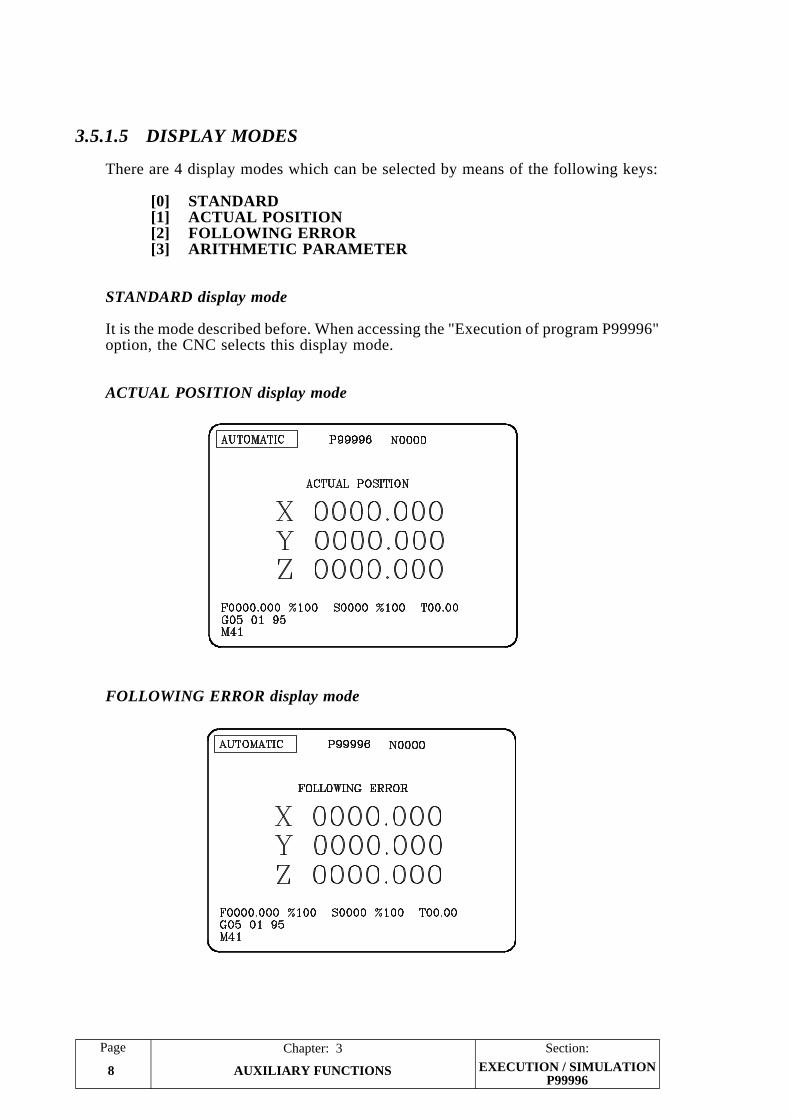
Section:Chapter: 3Page
AUXILIARY FUNCTIONS8 EXECUTION / SIMULATIONP99996
3.5.1.5 DISPLAY MODES
There are 4 display modes which can be selected by means of the following keys:
[0] STANDARD[1] ACTUAL POSITION[2] FOLLOWING ERROR[3] ARITHMETIC PARAMETER
STANDARD display mode
It is the mode described before. When accessing the "Execution of program P99996"option, the CNC selects this display mode.
ACTUAL POSITION display mode
FOLLOWING ERROR display mode

PageChapter: 3 Section:
AUXILIARY FUNCTIONS 9EXECUTION / SIMULATIONP99996
ARITHMETIC PARAMETERS display mode
This mode shows a group of 8 arithmetic parameters. To view the previous andfollowing ones, use these keys:
Displays the previous parameters
Displays the following ones
The value of each parameter may be expresssed in one of the following formats:
P46 = -1724.9281 Decimal notationP47 = -.10842021 E-2 Scientific notation
Where "E-2" means 10-2 (1/100). Therefore, the two types of notation for thesame parameter below have the same value:
P47= -0.001234 P47= -0.1234 E-2P48= 1234.5678 P48= 1.2345678 E3

Section:Chapter: 3Page
AUXILIARY FUNCTIONS10
3.5.2 SIMULATION OF PROGRAM 99996
With the 800M CNC, it is possible to check program 99996 in dry run before executingit.
To do this, press . The CNC will display a graphic screen.
The lower left-hand side of the screen shows the plane being represented and it ispossible to chose between the XY, XZ, YZ planes or the 3-D (XYZ).
For the CNC to show another plane, press the corresponding key:
[0] XY Plane[1] XZ Plane[2] YZ Plane[3] 3-D (XYZ)
This CNC may show the graphic representation in up to 3 planes; therefore, it willonly show those currently selected. To select other planes, proceed as follows:
Press , the CNC will ask whether each one of the possible planes is to beselected or not.
If wished to select the presented plane, press [Y] and if not, press [ENTER].
Once the desired planes have been indicated, select the display area by indicatingthe XYZ coordinates of the point appearing at the center of the screen and thewidth of the display area. Press [ENTER] after keying in each value.
To check the part, press and the corresponding graphic representation will begin.
While simulating, any other graphic plane is available (keys: 1, 2 and 3); but, noplanes or display areas may be selected. To select planes or modify display areas,the program simulation must be interrupted by pressing
To delete the graphic, press [CLEAR] and to quit the simulation mode, press [END].
EXECUTION / SIMULATIONP99996

PageChapter: 3 Section:
AUXILIARY FUNCTIONS 11
3.5.2.1 ZOOM FUNCTION
With the ZOOM function, it is possible to enlarge or shrink either the whole graphicor part of it. To do this, the simulation of the program must be interrupted or ended.
Once the representation plane to be enlarged or shrunk has been selected, press [Z].A rectangle will appear over the original graphic which represents the zoom window.
To alter the dimensions of this zoom window, use these keys:
Reduces the size of the window (greater enlargement).
Increases the size of the window (smaller enlargement).
To move the zoom window around, use:
When the desired window size and location has been selected, press [ENTER].
To see the selected zoom area enlarged while keeping the current display-area values,press
The section of the graphic enclosed in the zoom window will now occupy thewhole screen (zoom in).
To return to the previous whole area display (zoom out), press [END].
To zoom in again, just press [Z] and proceed as before.
To quit the ZOOM mode and return to the regular graphic representation, press [END].
EXECUTION / SIMULATIONP99996

Section:Chapter: 3Page
12 AUXILIARY FUNCTIONS
3.6 AUXILIARY MODES
When selecting this option, the CNC shows the following menu:
1 - SPECIAL MODES2 - PERIPHERALS3 - LOCK / UNLOCK
After accessing one of these modes and operate with it, press [END] to quit. At thispoint, the CNC will show this menu again. Press [END] once more to return to thestandard display mode.
3.7 SPECIAL MODES
When selecting this option, the CNC will request the password to access these auxiliarymodes. This password is the following:
0101
Once this code has been entered, the CNC displays the following menu:
0 - TEST1 - GENERAL PARAMETERS2 - DECODED M FUNCTIONS3 - LEADSCREW ERROR COMPENSATION
AUXILIARY MODES

PageChapter: 3 Section:
13AUXILIARY FUNCTIONS
3.7.1 TEST
To select this option, press [AUX], select the "Special Modes" option of the"Auxiliary Modes" menu, key in the password (0101) and press the keycorresponding to "TEST".
The CNC performs the General Test.
Once the test is completed, it is possible to test the logic inputs and outputs ofthe CNC, verify the checksum corresponding to the software version currentlyinstalled or perform the general test of the CNC again.
* Testing the logic inputs and outputs of the CNC.
Press [7] to access this option, the CNC will display the status of the logicINPUTS and it is possible to simulate the logic OUTPUTS of the CNC.
The inputs indicated by the letters "A" thru "M" have the meaning shown bythe chart below and their status is indicated by either a "0" or a "1".
A value of "0" means that it receives 0VA value of "1" means that it receives 24V
TEST
CNC LOGIC INPUTSMeaning Pin
A Cycle Start 17 (I/O1)
B Cycle Stop (It must be normally high) 16 (I/O1)
C Feed Hold (It must be normally high) 15 (I/O1)
D Emergency Stop (It must be normally high) 14 (I/O1)
E Only to be used by the Technical Department
F Z axis home switch 12 (I/O1)
G Y axis home switch 11 (I/O1)
H X axis home switch 10 (I/O1)
I Manual (DRO mode) 19 (I/O1)
J Block Skip (conditional input) 18 (I/O1)
K Only to be used by the Technical Department
L Only to be used by the Technical Department
M Only to be used by the Technical Department
N Only to be used by the Technical Department

Section:Chapter: 3Page
14 AUXILIARY FUNCTIONS
The logic outputs are shown in two rows under the letters "A" thru "M" andwith the meanings indicated by the chart below.
Each output may be assigned a "0" or "1" value which means:
If "0", the corresponding output will be at 0V (low).If "1", the corresponding output will be at 24V (high).
Use the up and down arrow keys to move the cursor and select the desiredoutputs.
* Checksum of the software version
Press [8] to access this option. The CNC will display the checksum of eachEPROM memory corresponding to the software version currently installed atthe CNC.
* New general test of the CNC
Press [9] to access this mode. The CNC will perform the general self-testagain.
After accessing one of these tests (inputs/outputs, checksum or general test), press[END] to return to the "AUXILIARY MODES" menu and press [END] again toreturn to the standard display mode.
TEST
TOP ROW BOTTOM ROWMeaning Pin Meaning Pin
A T Strobe 2 (I/O1) Output 1, decoded M 3 (I/O2)
B S Strobe 3 (I/O1) Output 2, decoded M 4 (I/O2)
C M Strobe 4 (I/O1) Output 3, decoded M 5 (I/O2)
D Emergency 5 (I/O1) Output 4, decoded M 6 (I/O2)
E Threading ON 6 (I/O1) Output 5, decoded M 7 (I/O2)
F Z axis Enable 7 (I/O1) Output 6, decoded M 8 (I/O2)
G Y axis Enable 8 (I/O1) Output 7, decoded M 9 (I/O2)
H X axis Enable 9 (I/O1) Output 8, decoded M 10 (I/O2)
I MST01 27 (I/O1) Output 9, decoded M 11 (I/O2)
J MST02 26 (I/O1) Output 10, decoded M 12 (I/O2)
K MST04 25 (I/O1) Output 11, decoded M 13 (I/O2)
L MST08 24 (I/O1) Output 12, decoded M 25 (I/O2)
M MST10 23 (I/O1) Output 13, decoded M 24 (I/O2)
N MST20 22 (I/O1) Output 14, decoded M 23 (I/O2)
O MST40 21 (I/O1) Output 15, decoded M 22 (I/O2)
P MST80 20 (I/O1) CNC in JOG mode 21 (I/O2)

PageChapter: 3 Section:
15AUXILIARY FUNCTIONS
3.7.2 GENERAL PARAMETERS
To select this option, press [AUX], select the "Special Modes" option of the "AuxiliaryModes" menu, key in the password (0101) and press the key corresponding to"GENERAL PARAMETERS".
The CNC shows the machine parameter table.
The operator may view the following or previous pages by means of the up anddown arrow keys.
To display a particular parameter, key in the desired parameter number and press[RECALL]. The CNC will then display the page corresponding to that parameter.
To EDIT a parameter, key in the desired parameter number, press [=] and then, keyin the desired value.
Depending on the type of machine parameter selected, the following types of valuesmay be assigned:
* A number P111 = 30000* A group of 8 bits P602 = 00001111* A character P105 = 1 (YES)
Once the machine parameter has been set, press [ENTER] for that value to be enteredon the table.
If when pressing [=], the parameter being edited disappears from the screen, it meansthat the machine parameters are protected and cannot be modified.
It must be borne in mind that once all the machine parameters are set, either the[RESET] key must be pressed or the CNC must be turned off and back on in orderfor these values to be assumed by the CNC.
To lock or unlock the access to the machine parameters, to the decoded M functiontable and to the leadscrew error compensation table, proceed as follows:
* Press [AUX] and after selecting the "Lock/Unlock" option of the of the "AuxiliaryModes" menu...
* Key in: "P1111" and press [ENTER] to lock the access or: "P0000" [ENTER]to unlock it.
When the access to the machine parameter table is locked, only those parametersrelated to the RS 232 serial communications line may be edited.
Remember that once the desired parameters have been edited, [RESET] must bepressed or the CNC must be turned off and back on in order for the CNC to assumethe new values.
The meaning of each parameter as well as the proper way to define them is describedin another chapter of this manual.
GENERAL PARAMETERS

Section:Chapter: 3Page
16 AUXILIARY FUNCTIONS
3.7.3 DECODED "M" FUNCTIONS
To lock or unlock the access to the machine parameters, to the decoded M functiontable and to the leadscrew error compensation table, proceed as follows:
* Press [AUX] and after selecting the "Lock/Unlock" option of the of the "AuxiliaryModes" menu...
* Key in: "P1111" and press [ENTER] to lock the access or: "P0000" [ENTER]to unlock it.
To select this option, press [AUX], select the "Special Modes" option of the "AuxiliaryModes" menu, key in the password (0101) and press the key corresponding to"DECODED M FUNCTIONS".
The CNC will show the decoded M function table.
The operator may view the following or previous pages by means of the up anddown arrow keys.
To view a particular M function, key in its number and press [RECALL]. The CNCwill then show the page corresponding to that function.
To EDIT a parameter, key in the desired parameter number, press [=], key in thedesired value and, then, press [ENTER] in order for this value to be entered on thetable.
When executing an "M" function, outputs M1 thru M15 of connector I/O 2 will bemodified depending on the setting of the corresponding function.
Two rows of "1s" and "0s" will appear to the right of each "M" function. The toprow has 15 characters and the bottom one 17.
The top-row characters have the following meaning:
0 Indicates the outputs which do not change when the M function is executed.They keep the previous status.
1 Indicates the outputs which are activated (set to 24V) when the M functionis executed.
The first 15 characters (from the left) of the bottom row have the following meaning:
0 Indicates the outputs which do not change when the M function is executed.They keep the previous status.
1 Indicates the outputs which are deactivated (set to 0V) when the M functionis executed.
For example: If the M41 table (first spindle speed range selection) has been set asfollows:
M41 100100100100100 (Outputs being activated)00100100100100100 (Outputs being deactivated)
The CNC will behave like this every time M41 is executed:
DECODED "M" FUNCTIONS

PageChapter: 3 Section:
17AUXILIARY FUNCTIONS
To activate the BCD outputs "MST01" thru "MST80" (pins 20 thru 27 of connectorI/O 1) besides, the decoded ones, machine parameter "P606 bit 7" must be set to "0".
Bit 16 of the bottom row indicates whether the "M" function is executed at thebeginning (0) of the block or at the end (1) once the programmed movements havebeen executed.
Bit 17 of the bottom row determines whether the CNC must wait for confirmationfrom the electrical cabinet indicating that the execution of the M function has beencompleted (M-done) or not before resuming the execution of the program.
This confirmation is carried out by means of the "M-DONE" input at pin 15 ofconnector I/O 1. This bit may be set as follows:
0 The CNC waits for the "M-DONE" confirmation signal from the electricalcabinet.
1 The CNC does not wait for the "M-DONE" confirmation signal fromthe electrical cabinet.
Up to 32 M functions may be set. All those empty M-table positions are indicated asM??.
Whenever a previously defined M function is redefined, the new setting replaces theold one.
DECODED "M" FUNCTIONS
M01 M02 M03 M04 M05 M06 M07 M08 M09 M10 M11 M12 M13 M14 M15
Pin I/O2 3 4 5 6 7 8 9 10 11 12 13 25 24 23 22
at 24V x x x x x
at 0V x x x x x
Notmodified
x x x x x

Section:Chapter: 3Page
18 AUXILIARY FUNCTIONS
3.7.3.1 M FUNCTIONS SENT OUT IN BCD
The CNC generates a series of M functions to indicate to the electrical cabinet thata certain event has taken place.
The CNC activates the BCD outputs corresponding to the generated "M" function(pins 20 thru 27 of connector I/O 1).
If besides activating these BCD outputs, the decoded outputs are also to be activated(pins 3 thru 13 and 22 thru 25 of connector I/O 2), the corresponding M functionsmust be defined at the decoded M-function table.
The CNC generates the following M-functions in BCD:
M00 At the end of the execution of each step of the selected operation while in"SINGLE" mode.
M03 When pressing the key to start the spindle clockwise.
M04 When pressing the key to start the spindle counter-clockwise.
M05 When pressing the key to stop the spindle.
M10 When pressing the key to turn on the external device O1.
M11 When pressing the key to turn off the external device O1.
M12 When pressing the key to turn on the external device O2.
M13 When pressing the key to turn off the external device O2.
M14 When pressing the key to turn on the external device O3.
M15 When pressing the key to turn off the external device O3.
M30 When pressing the RESET key of the CNC.
M41 When selecting the first spindle speed range.
M42 When selecting the second spindle speed range.
M43 When selecting the third spindle speed range.
M44 When selecting the fourth spindle speed range.
M FUNCTIONS IN BCD

PageChapter: 3 Section:
19AUXILIARY FUNCTIONS
3.7.4 LEADSCREW ERROR COMPENSATION
To select this option, press [AUX], select the "Special Modes" option of the "AuxiliaryModes" menu, key in the password (0101) and press the key corresponding to"LEADSCREW ERROR COMPENSATION".
The CNC will display the Leadscrew Error Compensation table.
The operator may view the following or previous pages by using the up and downarrow keys.
To view a particular parameter, key in its number and press [RECALL]. The CNCwill show the page corresponding to that parameter.
To clear the table by setting all the parameters to 0, key in the following sequence:[F] [S] [P] [ENTER].
There are up 30 parameter pairs for each axis. Parameters P0 thru P59 for the X axis,P60 thru P119 for the Y axis and P120 thru P179 for the Z axis.
Each parameter pair of this table represents:
Even parameter The position of the error point on the leadscrew. This position isreferred to Machine Reference Zero (home).
Value range: ±8388.607 millimeters±330.2599 inches
Odd parameter The amount of leadscrew error at that point.
Value range: ±32.766 millimeters±1.2900 inches
When defining the compensation points on the table, the following rules must beobserved:
* The even parameters are ordered according to their position along the axis. Thefirst pair of parameters (P0, P60, P120) must be set for the most negative (leastpositive) point of the axis to be compensated.
* If all 30 points of the table are not required, set the unused ones to 0.
* For those sections outside the compensation area, the CNC will apply thecompensation defined for the nearest point.
* The Machine Reference Zero point (home) must be set with an error of 0.
* The maximum difference between the error values of two consecutivecompensation points must be within: ±0.127 mm (±0.0050 inches)
* The inclination of the error graph between two consecutive points cannot begreater than 3%.
Examples: If the distance between two consecutive points is 3 mm. the maximumdifference of their relevant error values can be 0.090 mm.If the error difference between two consecutive points is the maximum(0.127mm), the distance between them cannot be smaller than4.233mm.
LEADSCREW ERRORCOMPENSATION

Section:Chapter: 3Page
20 AUXILIARY FUNCTIONS
To EDIT a parameter, key in its number, press [=], key in the desired value and press[ENTER] so the new value is entered on the table.
Remember to press [RESET] or power the CNC off and back on once the machineparameters have been set in order for the CNC to assume their new values.
Programming example:
An X axis leadscrew is to be compensated according to the following graph inthe section between X-20 and X160:
Considering that the machine reference point has a value of X30 (meaning thatit is located 30mm from the Machine Reference Zero ), the leadscrew errorcompensation parameters will be defined as follows:
P000 = X -20.000 P001 = X 0.001P002 = X 0.000 P003 = X -0.001P004 = X 30.000 P005 = X 0.000P006 = X 60.000 P007 = X 0.002P008 = X 90.000 P009 = X 0.001P010 = X 130.000 P011 = X -0.002P012 = X 160.000 P013 = X -0.003P014 = X 0.000 P015 = X 0.000P016 = X 0.000 P017 = X 0.000
" " " "" " " "
P056 = X 0.000 P057 = X 0.000P058 = X 0.000 P059 = X 0.000
LEADSCREW ERRORCOMPENSATION

PageChapter: 3 Section:
21AUXILIARY FUNCTIONS
3.8 PERIPHERALS
With this CNC it is possible to communicate with the FAGOR Floppy Disk Unit,with a general peripheral device or with a computer in order to transfer programsfrom and to one another. This communication may be managed either from the CNCwhen in the "Peripheral mode" or from the computer by means of FAGOR's DNCprotocol in which case the CNC may be in any of its operating modes.
3.8.1 PERIPHERAL MODE
In this mode, the CNC may communicate with the FAGOR Floppy Disk Unit, witha general peripheral device or with a computer having a standard off-the-shelfcommunications program.
To access this mode, press [AUX] and select the "Peripherals" option of the"Auxiliary modes" menu.
The upper left-hand side of The CNC screen will show the following menu:
0 - RECEIVE FROM (Fagor) FLOPPY DISK UNIT1 - SEND TO (Fagor) FLOPPY DISK UNIT2 - RECEIVE FROM GENERAL DEVICE3 - SEND TO GENERAL DEVICE4 - (Fagor) FLOPPY DISK UNIT DIRECTORY5 - (Fagor) DELETE FLOPPY DISK UNIT PROGRAM6 - DNC ON/OFF
In order to use any of these options, the DNC mode must be inactive. If it is active(the upper right-hand side of the screen shows: DNC), press [6] (DNC ON/OFF) todeactivate it (the DNC letters disappear).
With options 0, 1, 2 and 3 it is possible to transfer machine parameters, the decodedM function table and the leadscrew error compensation table to a peripheral device.
The lower right-hand side of the CNC screen will show a directory of up to 7 part-programs of the CNC.
To do this, key in the desired number when the CNC requests the number of theprogram to be transferred and press [ENTER].
P00000 to P99990 Corresponding to part-programsP99994 and P99996 Special user programs in ISO codeP99997 For internal use and CANNOT be transmitted back and
forthP99998 Used to associate texts to PLCI messagesP99999 Machine parameters and tables
Atention:
The part-programs cannot be edited at the peripheral device or computer.
The CRT will show the message: "RECEIVING" or "SENDING" during the programtransfer and the message: "PROGRAM NUM. P23256 (for example) RECEIVED"or "SENT" when the transmission is completed.
PERIPHERALS
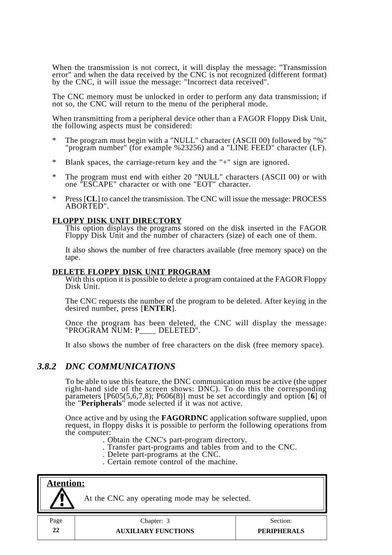
Section:Chapter: 3Page
22 AUXILIARY FUNCTIONS
When the transmission is not correct, it will display the message: "Transmissionerror" and when the data received by the CNC is not recognized (different format)by the CNC, it will issue the message: "Incorrect data received".
The CNC memory must be unlocked in order to perform any data transmission; ifnot so, the CNC will return to the menu of the peripheral mode.
When transmitting from a peripheral device other than a FAGOR Floppy Disk Unit,the following aspects must be considered:
* The program must begin with a "NULL" character (ASCII 00) followed by "%""program number" (for example %23256) and a "LINE FEED" character (LF).
* Blank spaces, the carriage-return key and the "+" sign are ignored.
* The program must end with either 20 "NULL" characters (ASCII 00) or withone "ESCAPE" character or with one "EOT" character.
* Press [CL] to cancel the transmission. The CNC will issue the message: PROCESSABORTED".
FLOPPY DISK UNIT DIRECTORYThis option displays the programs stored on the disk inserted in the FAGORFloppy Disk Unit and the number of characters (size) of each one of them.
It also shows the number of free characters available (free memory space) on thetape.
DELETE FLOPPY DISK UNIT PROGRAMWith this option it is possible to delete a program contained at the FAGOR FloppyDisk Unit.
The CNC requests the number of the program to be deleted. After keying in thedesired number, press [ENTER].
Once the program has been deleted, the CNC will display the message:"PROGRAM NUM: P____ DELETED".
It also shows the number of free characters on the disk (free memory space).
3.8.2 DNC COMMUNICATIONS
To be able to use this feature, the DNC communication must be active (the upperright-hand side of the screen shows: DNC). To do this the correspondingparameters [P605(5,6,7,8); P606(8)] must be set accordingly and option [6] ofthe "Peripherals" mode selected if it was not active.
Once active and by using the FAGORDNC application software supplied, uponrequest, in floppy disks it is possible to perform the following operations fromthe computer:
. Obtain the CNC's part-program directory.
. Transfer part-programs and tables from and to the CNC.
. Delete part-programs at the CNC.
. Certain remote control of the machine.
Atention:
At the CNC any operating mode may be selected.
PERIPHERALS

PageChapter: 3 Section:
23AUXILIARY FUNCTIONS
3.9 LOCK/UNLOCK
With this option it is possible to lock/unlock the machine parameters and the part-program memory.
To access this mode, press [AUX] and after selecting "Auxiliary Modes", press thekey corresponding to the "LOCK/UNLOCK" option.
The codes used to do this are:
[P] 0000 [ENTER] Unlocks the machine parameters.
[P] 1111 [ENTER] Locks the machine parameters.
[BEG] 0000 [ENTER] Unlocks part-program memory.
[BEG] 1111 [ENTER] Locks part-program memory.
[P] F000 [ENTER] Erases the contents of all arithmetic parameters (dataof the automatic operations) and sets them to "0".
LOCK / UNLOCK

Section:Chapter: 3Page
24 AUXILIARY FUNCTIONS EDITING P99996
3.10 EDITING PROGRAM 99996
Program 99996 is a special ISO-coded user program. It can be edited either in thisoperating mode or at a PC and then sent out to this CNC.
To select this option, press [AUX] and after selecting "Auxiliary Modes", press thekey corresponding to "EXECUTION OF PROGRAM P99996".
The CNC displays the editing page for this program.
If the program is currently being edited, the CNC shows a group of program blocks(lines).
Use the to display the display the previous and following lines.
To edit a new line, follow this procedure:
1.- If the program line number appearing at the bottom of the screen is not the desiredone, clear it by pressing [CL] and key in the desired line number.
2.- Key in all the pertinent data for that line and press [ENTER].
The programming format to be used is described in the programming manual.The keys on the front panel may be used: [X], [Y], [Z], [S], [F], [N] as well as:[TOOL] for T, for P, for R and for A.
However, since some function keys are missing (G, M, I, K, etc.), an assistededitor is also available.
To access it, press [AUX]. After analyzing the syntax of what has been edited sofar, the CNC will display, one by one, all the functions which can be edited atthe time.
Press [CL] to delete characters.
To modify a previously edited line, proceed as follows:
1.- If the program line number appearing at the bottom of the screen is not the desiredone, clear it by pressing [CL] and key in the desired line number.
2.- Press [RECALL]. The bottom of the screen of the CNC, editing area, will showthe contents of that line.
3.- Use one of these methods to modify the contents:
a) Use the [CL] key to delete characters and edit it as described above.
b) Use the keys to position the cursor over the section to be modifiedand use the [CL] key to delete characters or [INC/ABS] to insert data.

PageChapter: 3 Section:
25AUXILIARY FUNCTIONS EDITING P99996
While in the data inserting mode, the characters behind the cursor appearblinking. It is not possible to use assisted programming (the [AUX] key).
Key in all the desired data and press [INC/ABS]. If the syntax of the newline is correct, the CNC will display it without blinking and, if not, it willshow it blinking until it is edited correctly.
4.- Once the line has been modified, press [ENTER]. The CNC will assume itreplacing the previous one.
To delete a program line, proceed as follows:
1.- If the program line number appearing at the bottom of the screen is not the desiredone, clear it by pressing [CL] and key in the desired line number.
2.- Press [DATA] and the CNC will delete it from memory.

PageChapter: 4 Section:
MACHINE PARAMETERS 1
4. MACHINE PARAMETERS
Atention:
All unused machine parameters must be set to "0" to guarantee the properfunctioning of this CNC.
It is recommended to save the machine parameters of the CNC at aperipheral device or computer in order to be able to recover them aftertheir accidental loss.
Please note that some of the machine parameters mentioned here aredescribed in greater detail in the chapter on "CONCEPTS" in this manual.
4.1 INTRODUCTION
On power-up, the CNC performs a system hardware test. When completed, it displaysthe model name and the message "GENERAL TEST PASSED" when successful andthe corresponding error message if otherwise.
In order for the machine-tool to be able to properly execute the programmedinstructions and recognize the interconnected elements, the CNC must "know" thespecific data for the machine such as feedrates, acceleration ramps, feedback devices,etc.
This data is determined by the machine manufacturer and may be input via keyboardor via the RS232C serial line by setting the machine parameters.
To lock or unlock the access to the machine parameters, to the decoded M functiontable and to the leadscrew error compensation table, proceed as follows:
* Press [AUX] and after selecting the "Lock/Unlock" option of the of the "AuxiliaryModes" menu...
* Key in: "P1111" and press [ENTER] to lock the access or: "P0000" [ENTER]to unlock it.
When the access to the machine parameter table is locked, only those parametersrelated to the RS-232C serial communications line may be edited.
To enter the machine parameter values via the keyboard, press the following keystrokesequence:
[AUX] (SPECIAL FUNCTIONS)[5] (AUXILIARY MODES)[1] (SPECIAL MODES)[0] [1] [0] [1] (Access code, password)[1] (MACHINE PARAMETERS)
INTRODUCTION

Section:Chapter: 4Page
MACHINE PARAMETERS2
4.2 OPERATING WITH PARAMETER TABLES
Once the machine parameter table has been selected, the operator may view thefollowing or previous pages by means of the up and down arrow keys.
To view a particular parameter, key in the desired parameter number and press[RECALL]. The CNC will display the page corresponding to that parameter.
To EDIT a parameter, key in the desired number, press [=] and key in the value tobe assigned to that parameter.
Depending on the type of machine parameter selected, it could be assigned one ofthe following types of values:
* A number P111 = 30000* A group of 8 bits P602 = 00001111* A character P105 = Y
Once the value of the parameter has been keyed in, press [ENTER] so it is enteredon the table.
If when pressing [=], the parameter being edited disappears from the screen, it meansthat the machine parmeters are locked, therefore protected against modifications.
Every time a parameter bit is mentioned while describing the different machineparameters, refer to this nomenclature:
P602 = 0 0 0 0 1 1 1 1Bit 1Bit 2Bit 3Bit 4Bit 5Bit 6Bit 7Bit 8
OPERATING WITHPARAMETER TABLES

PageChapter: 4 Section:
MACHINE PARAMETERS 3
4.3 GENERAL MACHINE PARAMETERS
P5 AC frequency
Possible values: 50 Hz. and 60 Hz.
P99 Language
Determines the language used by the CNC to show texts and messages on thescreen. 0 = Spanish. 1 = German. 2 = English. 3 = French. 4 = Italian.
P13 Measuring units (mm/inches)
It determines the measuring units assumed by the CNC for machine parameters,tool tables and work units at power-up, after executing M02 or M30 and afterRESET.
0 = Millimeters (G71). 1 = Inches (G70).
P6 Theoretical or Real display
It determines whether the CNC will display the real axis position or the theoreticalposition.
0 (REAL)= The CNC displays the real position values (coordinates).1 (THEO)= The CNC displays the theoretical position values (ignoring the
following error).
P617(5), P605(6), P617(4) The X, Y, Z axis is a DRO axis.
It indicates whether the corresponding axis is treated as a normal axis (controlledby the CNC) or a DRO axis (moved externally).
0 = Normal axis. 1 = DRO axis.
P618(6), P618(5), P618(4) The X, Y, Z axis display
It indicates whether the corresponding axis is displayed on the CRT or not.
0 = It is displayed. 1 = It is not displayed.
P701 Number of tools
It is given by an integer between 0 and 98.
P626(1) The CNC displays the tool base position
It indicates whether the CNC displays the tool base or tool tip position whenworking with tool length compensation (G43).
0 = It displays the tool tip position.1 = It displays the tool base position.
Atention:
When not working with tool length compensation (G44), the CNC alwaysdisplays the tool base position.
GENERAL

Section:Chapter: 4Page
MACHINE PARAMETERS4
P743 Subroutine to be executed before the T functionP745 Subroutine to be executed after the T function
The CNC takes these parameters into consideration when executing the ISO-coded user program 99996.
They indicate the number of the standard (non-parametric) subroutine to beexecuted by the CNC whenever a tool is selected in the execution of program99996.
These standard subroutines must contain the tool selecting sequence.
They are set by an integer between 0 and 99. If set with a "0" value, the CNCassumes that no subroutine is to be executed.Every time a new tool is selected in ISO code, the CNC behaves as follows:
1.-It executes the subroutine indicated by P743. If set to "0", the CNC will displaythe message: "TOOL CHANGE" (in English for all language versions) and itinterrupts program execution.
2.-The CNC outputs the code for the new tool.
3.-It executes the subroutine indicated by P745. If set to "0", no subroutine isexecuted.
Atention:
When a subroutine is associated with the T function, nothing must beprogrammed in that block after the T function; otherwise, the CNC willissue the corresponding error.
The subroutines associated with the T function must be defined in oneof the special ISO-coded user programs: P99994 or P99996.
P628(1) Display of the Following Error.
Enter: 0 = No, the Following Error is not displayed.1 = Yes, the Following Error is displayed.
It is recommended to set to to "1" during machine set-up and then set it to "0"for normal operation.
P628(6) External device O1 may only be turned on/off when spindle stopped.
Enter: 0 = It may be turned on/off at any time, whether the spindle is on oroff.
1 = It may be turned on/off only when the spindle is off.
GENERAL

PageChapter: 4 Section:
MACHINE PARAMETERS 5
4.3.1 INPUT/OUTPUT PARAMETERS
P605(8) Normal status of the Emergency output (pin 5 connector I/O 1)
It determines whether the emergency output is normally low or high.
0 = Normally low (0V). An emergency situation will set this output high (24V)
1 = Normally high (24V). An emergency situation will set this output low(0V)
P605(5) The CNC waits for the trailing edge of the M-DONE input signal
It indicates whether it is necessary or not to wait for the down flank (24V-to-0Vtransition) of the M-DONE signal (at pin 15 of connector I/O 1) in response toan "S STROBE", "T STROBE" or "M STROBE" so the CNC resumes theexecution of such functions.
“P605(5)=0”
The CNC will send out to the electrical cabinet the BCD signals correspondingto the M, S or T code for a period of 200 milliseconds. Then, if the "M-DONE"signal is low (0V), it will wait for it to be set high (24V) in order to considerthe M, S or T function done (completed).
I/O PARAMETERS

Section:Chapter: 4Page
MACHINE PARAMETERS6
“P605(5)=1”
50 milliseconds after having sent the M, S or T BCD signals out to the electricalcabinet, it sends out the corresponding "Strobe" signal.
Then, if the "M-DONE" signal is high (24V), the CNC waits for it to be setlow (0V).
Once the "M-done" signal is set low, the CNC continues maintaining the"Strobe" signal active for another 100 milliseconds.
After deactivating the Strobe signal, the M, S T BCD code signals are keptactive for another 50 milliseconds.
After that time and if the "M-DONE signal is low, the CNC will wait until itbecomes high so it can consider the auxiliary function M, S or T completed.
P609(7) Pin 17 of connector I/O 1 as RAPID TRAVERSE (fast feed)
It determines whether the signal input at pin 17 of connector I/O1 is treated asEXTERNAL CYCLE START or RAPID TRAVERSE.
0 = It is treated as EXTERNAL CYCLE START.1 = It is treated as RAPID TRAVERSE.
If set as Rapid Traverse and while this input is active, the CNC will carry out allG01, G02 and G03 moves at 200% of the programmed feedrate F.
By the same token, in the JOG mode and while this input is kept active, the CNCwill jog the axes in rapid G00.
I/O PARAMETERS

PageChapter: 4 Section:
MACHINE PARAMETERS 7
P609(3) Pin 23 of connector I/O 2 as RESET output
Indicates whether there is or not a RESET output via pin 23 of connector I/O2.
0 = It is not used as RESET output.1 = It is used as RESET output.
It must be borne in mind that this pin is also used as output 14 of the decodedM functions; therefore, it should not be set on the decoded M function tablewhen this parameter is set to output a RESET signal (set to "1").
P611(1) Pin 24 of connector I/O 2 as program block in executionP611(6) Pin 24 of connector I/O 2 as program P99996 in executionP613(4) Pin 24 of connector I/O 2 as rapid move in progress
If machine parameter P611(1) is set to "1", the CNC sets this OUTPUT high(24V) every time a part-program block is being executed.
If machine parameter P611(6) is set to "1", the CNC sets this OUTPUT high(24V) whenever the special ISO-coded user program P99996 is being executed.
If machine parameter P613(4) is set to "1", the CNC sets this OUTPUT high(24V) whenever the CNC is executing a rapid positioning move
Care must be taken, when having one of these options, not to use the bit of thedecoded M table corresponding to this output M13 since the CNC will activateit in all these cases.
0 = Used as output 13 of decoded M functions.1 = Used as the corresponding indicator output and output 13 of the "M"
functions.
When setting two or three of these parameters to "1", the CNC will only outputone of them being P611(1) the one with the highest priority and P613(4) the onewith the lowest.
P613(2) Pin 25 of connector I/O 2 as "Vertical axis movement" indicatoroutput
It determines whether or not pin 25 of connector I/O2 is used to indicate thedirection of the vertical axis movement. This output will be low (0V) for positivedirection (count-up) or high (24V) for negative direction (count-down).
0 = It is not used as vertical axis moving direction indicator output.1 = It is used as vertical axis moving direction indicator output.
It must be borne in mind that this pin is also used as output 12 of the decodedM functions; therefore, it should not be set on the decoded M function tablewhen this parameter is set for the output to be used as vertical axis moving directionindicator (set to "1").
I/O PARAMETERS

Section:Chapter: 4Page
MACHINE PARAMETERS8
P617(8) M functions output in BCD or BINARY code
It determines whether the M function is output in BCD or Binary code via pins20 thru 27 of connector I/O1.
0 = M function output in BCD code1 = M function output in BINARY code
The significance or weight of each pin in both cases is as follows:
Pin M in BCD M in BINARYWEIGHT WEIGHT
27 1 126 2 225 4 424 8 823 10 1622 20 3221 40 6420 80 128
For example: Depending on the type of code selected, the CNC will output theM41 as follows:
Pin 20 21 22 23 24 25 26 27
BCD 0 1 0 0 0 0 0 1
Binary 0 0 1 0 1 0 0 1
P609(5) Decoded M function code output in BCD or BINARY.
When executing an M function which is decoded on the table, the CNC activatesthe decoded outputs of connector I/O2.
This parameter determines whether or not the CNC activates the M-BCD outputsof connector I/O1 (pins 20 thru 27) besides the decoded M outputs of connectorI/O2.
0 = It also outputs the M function in BCD or BINARY code.1 = It does not output the M function in BCD or BINARY code.
I/O PARAMETERS

PageChapter: 4 Section:
MACHINE PARAMETERS 9
P602(8), P602(7), P602(6), P602(5), P603(1) Feedback alarm cancellation of theA1, A2, A3, A4 and A5 connectors
The CNC will show the axis feedback alarm when not receiving all itscorresponding feedback signals or when any of them is not within the permittedlevels.
This parameter indicates whether this feedback alarm is to be cancelled or not.
0 = The feedback alarm for the corresponding axis is not cancelled.1 = The feedback alarm for the corresponding axis is cancelled.
If the feedback system being used only utilizes 3 square-wave signals (A, B andIo), the corresponding parameter must be set to "1" (feedback alarm for that axiscanceled).
I/O PARAMETERS

Section:Chapter: 4Page
MACHINE PARAMETERS10
4.3.2 MACHINE PARAMETERS FOR THE HANDWHEELS
P612(1) There is an electronic handwheel associated with the X axis.P626(8) There is an electronic handwheel associated with the Y axis.P627(8) There is an electronic handwheel associated with the Z axis.
0 = There is no electronic handwheel for this axis.1 = There is an electronic handwheel for this axis.
P613(1) The connected handwheel is a FAGOR 100P model
This parameter is relevant when using a single handwheel associated to the Xaxis and it indicates whether or not it is a FAGOR 100P model with axis selectorbutton.
0 = It is not a FAGOR 100P model.1 = It is a FAGOR 100P model.
P612(2) Counting direction of the X axis handwheel.P626(2) Counting direction of the Y axis handwheel.P627(2) Counting direction of the Z axis handwheel.
Define the counting direction of the electronic handwheel. If correct, leave it asis; if not, change it.
Possible values: “0” and “1”
P612(3) Feedback units for the X axis handwheel.P626(3) Feedback units for the Y axis handwheel.P627(3) Feedback units for the Z axis handwheel.
Indicate whether the feedback pulses provided by the handwheel correspond tomillimeters or inches.
0 = millimeters.1 = inches.
P612(4,5) Feedback resolution of the X axis handwheel.P626(4,5) Feedback resolution of the Y axis handwheel.P627(4,5) Feedback resolution of the Z axis handwheel.
Indicate the counting resolution of the electronic handwheel. That is, the distancecorresponding to each square feedback pulse. The possible values are:
bit (4) bit (5) Resolution
0 0 0.001 mm or 0.0001 inch0 1 0.002 mm or 0.0002 inch1 0 0.005 mm or 0.0005 inch1 1 0.010 mm or 0.0010 inch
HANDWHEELPARAMETERS

PageChapter: 4 Section:
MACHINE PARAMETERS 11
P612(6) Multiplying factor for the X axis handwheel signals.P626(6) Multiplying factor for the Y axis handwheel signals.P627(6) Multiplying factor for the Z axis handwheel signals.
Indicate the x2 or x4 multiplying factor that the CNC will apply to the feedbacksignals provided by the electronic handwheel.
0 = x4.1 = x2.
Example: If the X axis handwheel has been set as follows:
P612(3) = 0 MillimetersP612(4) = 0 & P612(5) = 0 Resolution 0.001 mm.P612(6) = 0 x4
The F.O.S. is at "x100" position.
The X axis will move 0.001mm x4 x100 = 0.4 mm per handwheelpulse received.
P628(5) The handwheels operate at all "handwheel" positions of the switch
0 = The electronic handwheels only operate at the positions of the FeedrateOverride Switch indicated by the symbol.
1 = The electronic handwheels operate at all the positions of the FeedrateOverride Switch. At those positions indicated by the symbol, the CNCapplies the selected pulse multiplying factor (x1, x10, x100) and applies ax1 factor at the other positions of the switch.
P628(8) The machine uses mechanical handwheels
0 = The machine does not use mechanical handwheels.
1 = The machine uses mechanical handwheels.
When using mechanical handwheels, "P628(8) =1", machine parameters P105,P205 and P305 must be set to "N" so the axes are not continuously controlled.In other words, they are not held in position once they reach their in-position(dead-band) zone.
P815 Delay before opening the loop
This parameter only applies when the machine uses mechanical handwheels and,therefore, machine parameters "P628(8)=1", "P105=N", "P205=N", and "P305=N".
It indicates the time delay from the moment the axes reach position to when theCNC opens their position loops.
It is expressed by an integer between 0 and 255.
Value of "0" = No delay is applied.Value of "1" = 10 milliseconds.Value of "10" = 100 milliseconds.Value of "255" = 2550 milliseconds.
HANDWHEELPARAMETERS

Section:Chapter: 4Page
MACHINE PARAMETERS12
4.3.3 PARAMETERS RELATED TO THE OPERATING MODE
P609(8) Graphic representation of coordinate system
Mill model Boring Mill model
P605(4) XZ plane representation
P628(7) Interpolations with the Z axis
0 = Any two- or three-axis interpolation is possible ( XY, XZ, YZ and XYZ)
1 = No interpolation involving the Z axis is possible. When programminga movement which includes the Z axis, the CNC will first move the Zaxis and then the XY axes.
P618(1) Disabling the CYCLE START key
It indicates whether the CYCLE START key of the operator panel is cancelled(ignored by the CNC) or not.
0 = The CYCLE START key is not disabled.1 = The CYCLE START key is disabled (ignored by the CNC).
P606(3) M30 when switching to JOG mode
It indicates whether the CNC must generate an M30 automatically or not whenswitching to the JOG mode.
0 = M30 is not generated.1 = M30 is generated.
OPERATING MODEPARAMETERS

PageChapter: 4 Section:
MACHINE PARAMETERS 13
P12 Continuous or pulsating axis jog
It indicates whether the axes are jogged while their corresponding jog keys arepressed (pulsating) or their movements are maintained until the CYCLE STOPkey or another jog key is pressed (continuous).
0 = Continuous mode. The axis starts moving when its corresponding jogkey is pressed and it stops when the CYCLE STOP key or another jogkey is pressed. In this latter case, the CNC will move the new selectedaxis in the chosen direction until the CYCLE STOP key or another jogkey is pressed.
1 = Pulsating mode. The axis is jogged as long as its corresponding jog keyis maintained pressed.
P609(6) Maximum incremental JOG move
It indicates the maximum distance the axes can be jogged when selecting one ofthe JOG positions of the Feedrate Override Switch on the operator panel (positions1, 10, 100, 1000, 10000).
0 = Limited to 10 mm. or 1 inch.1 = Limited to 1 mm. or 0.1 inch.
P606(2) Maximum value of the Manual Feedrate Override
It indicates the maximum feedrate override value to be selected by the ManualFeedrate Override Switch at the operator panel.
0 = Possible up to 120%.1 = Limited to 100% even when selecting the 110% and 120% switch positions.
P4 The Manual Feedrate Override switch active in G00
It indicates whether it is possible or not to override the axis feedrate by thisswitch when moving in G00 (rapid positioning).
NO The feedrate override switch is ignored when in G00.
YES The feedrate override switch is active (not ignored) when in G00 applyinga range from 0% to 100% of the maximum feedrate set by machineparameters P111, P211, P311, P411 and P511 even at 110% and 120%positions.
P613(5) G05 or G07 active on power-up
It indicates whether the CNC assumes function G05 (round corner) or G07 (squarecorner) on power-up, after M02, M30, EMERGENCY or RESET.
0 = G07 (square corner).1 = G05 (round corner).
OPERATING MODEPARAMETERS

Section:Chapter: 4Page
MACHINE PARAMETERS14
P715 Dwell between blocks in G07 (square corner)
It defines the dwell applied to motion blocks in G07.
It is given by an integer between 0 and 255.
Value 0 = No dwell.Value 1 = 10 msec.Value 10 = 100 msec.Value 255 = 2550 msec.
P611(5) Feedrate units in G94
It determines the F programming units when function G94 is active.
0 = 1 mm./minute or 0.1 inch/minute.1 = 0.1 mm./minute or 0.01 inches/minute.
If parameter "P611(5)=1", it is working in mm and F0.1 is programmed, theapplied feedrate will be F0.01 mm/min.
It must be borne in mind that the machine parameters corresponding to themaximum programmable feedrate F0 (P110/210/310), the maximum feedrate inG00 (P111/211/311), the home searching feedrate (P112/212/312) and theunidirectional approach feedrate (P801) are not affected by this parameter.They are expressed in 1 mm/min or 0.1 inch/min units.
P610(1) FEED-HOLD in G47
It indicates whether the CNC stops the movement of the axes while the FEED-HOLD input is active while in G47 (single block treatment).
0 = The FEED-HOLD input does not stop the axes.1 = The FEED-HOLD input stops the axes.
OPERATING MODEPARAMETERS
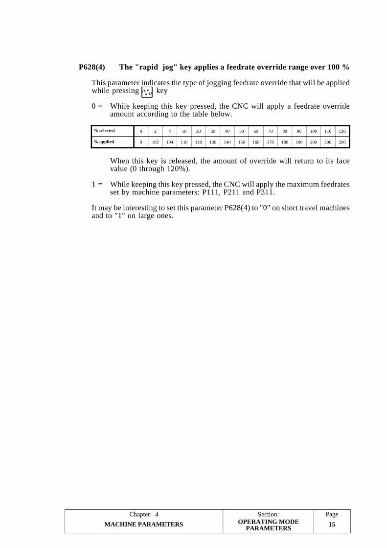
PageChapter: 4 Section:
MACHINE PARAMETERS 15
% selected 0 2 4 10 20 30 40 50 60 70 80 90 100 110 120
% applied 0 102 104 110 120 130 140 150 160 170 180 190 200 200 200
OPERATING MODEPARAMETERS
P628(4) The "rapid jog" key applies a feedrate override range over 100 %
This parameter indicates the type of jogging feedrate override that will be appliedwhile pressing key
0 = While keeping this key pressed, the CNC will apply a feedrate overrideamount according to the table below.
When this key is released, the amount of override will return to its facevalue (0 through 120%).
1 = While keeping this key pressed, the CNC will apply the maximum feedratesset by machine parameters: P111, P211 and P311.
It may be interesting to set this parameter P628(4) to "0" on short travel machinesand to "1" on large ones.

Section:Chapter: 4Page
MACHINE PARAMETERS16
4.3.4 MACHINE PARAMETERS FOR THE RS232C SERIAL LINE
P0 Transmission speed (baudrate)
It determines the transmission baudrate used in communications between theCNC and the peripheral devices.
It is given by an integer (9600 maximum) and in baud units.
Typical values:
110, 150, 300, 600, 1200, 2400, 4800, 9600
P1 Data bits per transmitted character
It determines the number of data bits used in each transmitted character.
Possible values:
7 = Only the 7 least significant bits (out of 8) are used. Assign this valuewhen transmitting standard ASCII characters.
8 = All 8 bits of the transmitted character are used. Assign this value whentransmitting special characters (ASCII code over 127).
P2 Parity
It determines the type of parity check used in the transmission.
Possible values:
0 = None.1 = ODD parity.2 = EVEN parity.
P3 Stop bits
It determines the number of stop bits used at the end of the transmitted word.
Possible values:
1 = 1 stop bit.2 = 2 stop bits.
P607(3) DNC
It indicates whether the CNC can work with the DNC protocol or not.
0 = DNC function not available.1 = DNC function available.
RS232C SERIAL LINE

PageChapter: 4 Section:
MACHINE PARAMETERS 17
P607(4) Communication settings for the FAGOR Floppy Disk Unit orCassette.
P607(4)=1 For Floppy Disk Unit. The CNC uses the values set for machineparameters P0, P1, P2 and P3.
P607(4)=0 For Cassette Unit. The CNC does not modify the P0, P1, P2 andP3 settings but uses the values corresponding to the FAGORCassette Unit.
Baudrate: 13,714 BaudData bits: 7Parity: EvenStop bits: 1
Atention:
In DNC and Peripheral communications, use the settings of machineparameters P0, P1, P2 and P3.
P607(5) DNC protocol active on power-up
It indicates whether the DNC protocol is active on CNC power-up or not.
0 = DNC not active on power-up.1 = DNC active on power-up.
P607(6) The CNC does not abort DNC communication (program debugging)
The CNC offers a safety system that aborts DNC communications whenever:
* More than 30 seconds elapse without receiving a character while in the receptionmode.
* More than 3 incorrect acknowledgments or non-acknowledgments occur in arow while in transmission mode.
This parameter can be used in order to be able to debug a user communicationsprogram without the CNC aborting the communication.
0 = The CNC aborts communications.1 = The CNC does not abort communications (Debug mode).
P607(7) Status report by interruption
It indicates whether the "status report by interruption" is active or not while inDNC mode.
0 = It is not active.1 = It is active.
A more detailed explanation on this function can be found in the "DNCCOMMUNICATIONS PROTOCOL FOR THE 8025 CNC" manual.
RS232C SERIAL LINE

PageChapter: 5 Section:
MACHINE PARAMETERS FOR THE AXES 1
Atention:
Observe that some of the parameters mentioned in this chapter are alsodescribed in more detail in the chapters on "power and machine interface"and "concepts" in this manual.
P100, P200, P300 Sign of the analog voltage for X, Y, Z axes
It determines the sign of the analog voltage for the axis servo drive. If correct,leave it as is and change it if otherwise.
Possible values: “0” and “1”.
P101, P201, P301 Sign of the X, Y, Z axis feedback
It determines the counting direction of the axis. If correct, leave it as is andchange it if otherwise.
Possible values: “0” and “1”.
Observe that when changing this parameter, the one corresponding to the sign ofthe analog voltage must also be changed to prevent the axis from running away(P100, P200, P300).
P102, P202, P302 X, Y, Z axis jogging direction
It establishes the axis jogging direction by means of the JOG keys of the operatorpanel.
It determines the counting direction of the axis. If correct, leave it as is andchange it if otherwise.
Possible values: “0” and “1”.
5. MACHINE PARAMETERS FOR THE AXES

Section:Chapter: 5Page
MACHINE PARAMETERS FOR THE AXES2
5.1 PARAMETERS RELATED TO AXIS RESOLUTION
The section on "Axis resolution" in the chapter on "concepts" of this manualdescribes how these parameters may be used.
P103, P203, P303 X, Y, Z axis feedback resolution
They indicate the counting resolution for the axis.Possible values for square-wave signals:
1 = Resolution of 0.001 mm, 0.0001 inch. 2 = Resolution of 0.002 mm, 0.0002 inch. 5 = Resolution of 0.005 mm, 0.0005 inch.10 = Resolution of 0.010 mm, 0.0010 inch.
The units used depend on the setting of the following parameters:
P604(4,3,2) In millimeters or inches.
P622(1), P622(2), P622(3) Counting resolution for X, Y, Z, axis with sine-wavefeedback
When using sine-wave feedback signals, the CNC considers these parameters aswell as P103, P203 and P303, to set the axis resolution.
Possible values for P103, P203, and P303 with P622(1), P622(2), P622(3) = 0:
5 = Resolution of 0.001 mm, 0.0001 inch.10 = Resolution of 0.002 mm, 0.0002 inch.
Possible values for P103, P203 and P303 with P622(1), P622(2), P622(3) = 1:
1 = Resolution of 0.001 mm, 0.0001 inch. 2 = Resolution of 0.002 mm, 0.0002 inch. 5 = Resolution of 0.005 mm, 0.0005 inch.10 = Resolution of 0.010 mm, 0.0010 inch.
P604(4), P604(3), P604(2) X, Y, Z feedback units
They indicate the units of the feedback pulses for the corresponding axis.
0 = Millimeters.1 = Inches.
P106, P206, P306 X, Y, Z axis feedback signal type
They indicate the type of feedback signals being used.
0 = Square-wave feedback signals1 = Sine-wave feedback signals
The CNC always applies a x5 multiplying factor to the sine-wave feedback signals.
AXIS RESOLUTION

PageChapter: 5 Section:
MACHINE PARAMETERS FOR THE AXES 3
P604(8), P604(7), P604(6) Multiplying factor for X, Y, Z axis feedback signals
It indicates whether the CNC applies a x2 or x4 multiplying factor to the feedbacksignals of the axes.
0 = It applies a x4 factor.1 = it applies a x2 factor.
When using FAGOR linear transducers (scales), set the corresponding parametersto "0".
Setting examples for the X axis:
Using square-wave linear transducers (scales):
Since the CNC applies either a x2 or x4 multiplying factor, a linear transducermust be selected which has a signal period of twice or four times the desiredresolution.
Using sine-wave linear transducers and P622(1)=1:
Besides the x2 or x4 selected by P604(8), the CNC applies an additional x5 factorto the sinewave signals. Therefore, a transducer must be chosen which has afeedback signal period 10 or 20 times the desired resolution.
If parameter P622(1)=1, it is possible to obtain resolution of 1, 2, 5 and 10 micronsor ten-thousandths of an inch.
AXIS RESOLUTION
Desired resolutionP103 P604(8)
FeedbackSignal period
FAGORLinear transducerP604(4)=0 P604(4)=1
0.001 mm 0.0001 inch 1x2 P604(8)=1 0.002 mmx4 P604(8)=0 0.004 mm CX, CVX, MX
0.002 mm 0.0002 inch 2x2 P604(8)=1 0.004 mm CX, CVX, MX
x4 P604(8)=0 0.008 mm
0.005 mm 0.0005 inch 5x2 P604(8)=1 0.010 mmx4 P604(8)=0 0.020 mm CT, CVT, MT, MVT, FT
0.010 mm 0.0010 inch 10x2 P604(8)=1 0.020 mm CT, CVT, MT, MVT, FT
x4 P604(8)=0 0.040 mm
Desired resolutionP103 P604(8)
Feedbacksignal period
FAGORLinear transducerP604(4)=0 P604(4)=1
0.001 mm 0.0001 inch 1x2 P604(8)=1 0.010 mmx4 P604(8)=0 0.020 mm CC,CVC,CVS,MC,MVC,
0.002 mm 0.0002 inch 2x2 P604(8)=1 0.020 mm CC,CVC,CVS,MC,MVC,
x4 P604(8)=0 0.040 mm
0.005 mm 0.0005 inch 5x2 P604(8)=1 0.050 mmx4 P604(8)=0 0.100 mm FS
0.010 mm 0.0010 inch 10x2 P604(8)=1 0.100 mm FS
x4 P604(8)=0 0.200 mm
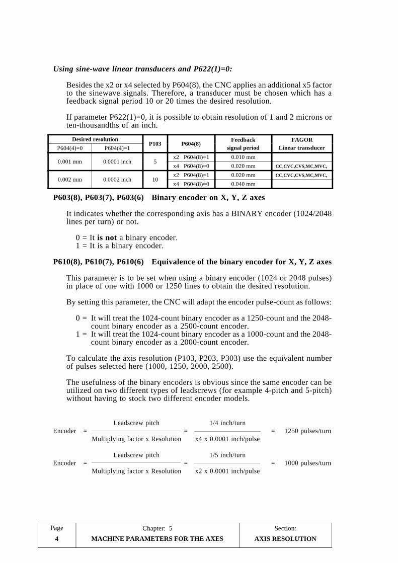
Section:Chapter: 5Page
MACHINE PARAMETERS FOR THE AXES4
Using sine-wave linear transducers and P622(1)=0:
Besides the x2 or x4 selected by P604(8), the CNC applies an additional x5 factorto the sinewave signals. Therefore, a transducer must be chosen which has afeedback signal period 10 or 20 times the desired resolution.
If parameter P622(1)=0, it is possible to obtain resolution of 1 and 2 microns orten-thousandths of an inch.
P603(8), P603(7), P603(6) Binary encoder on X, Y, Z axes
It indicates whether the corresponding axis has a BINARY encoder (1024/2048lines per turn) or not.
0 = It is not a binary encoder.1 = It is a binary encoder.
P610(8), P610(7), P610(6) Equivalence of the binary encoder for X, Y, Z axes
This parameter is to be set when using a binary encoder (1024 or 2048 pulses)in place of one with 1000 or 1250 lines to obtain the desired resolution.
By setting this parameter, the CNC will adapt the encoder pulse-count as follows:
0 = It will treat the 1024-count binary encoder as a 1250-count and the 2048-count binary encoder as a 2500-count encoder.
1 = It will treat the 1024-count binary encoder as a 1000-count and the 2048-count binary encoder as a 2000-count encoder.
To calculate the axis resolution (P103, P203, P303) use the equivalent numberof pulses selected here (1000, 1250, 2000, 2500).
The usefulness of the binary encoders is obvious since the same encoder can beutilized on two different types of leadscrews (for example 4-pitch and 5-pitch)without having to stock two different encoder models.
Leadscrew pitch 1/4 inch/turnEncoder = = = 1250 pulses/turn
Multiplying factor x Resolution x4 x 0.0001 inch/pulse
Leadscrew pitch 1/5 inch/turnEncoder = = = 1000 pulses/turn
Multiplying factor x Resolution x2 x 0.0001 inch/pulse
AXIS RESOLUTION
Desired resolutionP103 P604(8)
Feedbacksignal period
FAGORLinear transducerP604(4)=0 P604(4)=1
0.001 mm 0.0001 inch 5x2 P604(8)=1 0.010 mmx4 P604(8)=0 0.020 mm CC,CVC,CVS,MC,MVC,
0.002 mm 0.0002 inch 10x2 P604(8)=1 0.020 mm CC,CVC,CVS,MC,MVC,
x4 P604(8)=0 0.040 mm

PageChapter: 5 Section:
MACHINE PARAMETERS FOR THE AXES 5
5.2 PARAMETERS RELATED TO THE ANALOG OUTPUTS
The section on "Adjustment of the axes" in the chapter on "concepts" of thismanual describes how these parameters may be used.
P117, P217, P317 Minimum analog for X, Y, Z axes
They determine the minimum analog values for the axes.
It is given by an integer between 1 and 255.
Value 1 = 2.5 mV.Value 10 = 25.0 mV. (10 x 2.5)Value 255 = 637.5 mV. (255 x 2.5)
P104, P204, P304 Enable-Analog delay for X, Y, Z axes
They indicate whether there is 400 msec delay from the time the axis ENABLEsignal is activated to when its analog voltage is output.
0 = There is no delay.1 = There is delay.
This parameter is used when the axis is not continuously controlled (held inposition by the CNC) and some time it is required to deactivate certain devicessuch as a holding brake, etc.
P118, P218, P318 In-position zone (dead-band) for X, Y, Z
They define the in-position zone (to either side of the programmed coordinatevalue) where the CNC considers the axis to be in position.
It is always expressed in microns regardless of the work units being used.
Possible values: 0 thru 255 microns.
P105, P205, P305 Continuous control of the X, Y, Z axes
They determine whether or not the axis is held in position by the CNC by keepingits ENABLE signal ON when reaching its target position.
1 = It is continuously controlled (ENABLE on when in position).0 = It is not continuously controlled (ENABLE off when in position)
RELATED TO ANALOGOUTPUTS

Section:Chapter: 5Page
MACHINE PARAMETERS FOR THE AXES6
5.3 PARAMETERS RELATED TO TRAVEL LIMITS
The section on "Adjustment of the axes" in the chapter on "concepts" of thismanual describes how these parameters may be used.
P107, P207, P307 Positive travel limit for X, Y, Z axesP108, P208, P308 Negative travel limit for X, Y, Z axes
They establish the positive and negative travel limits for the axes. These distancesare referred to machine reference zero (home).
Possible values: ± 8388.607 millimeters.± 330.2599 inches.
If both limits are assigned the same value (for example: 0), the CNC will notallow to move the axis.
In JOG mode, and for safety reasons, it is possible to move the axis only up to100 microns from the travel limits set by these parameters.
AXIS TRAVEL LIMITS

PageChapter: 5 Section:
MACHINE PARAMETERS FOR THE AXES 7
5.4 FEEDRATE RELATED PARAMETERS
P110, P210, P310 Maximum programmable feedrate for X, Y, Z
They determine the maximum programmable feedrate F0 for the axes.
Possible values: 1 thru 65,535 mm./minute.1 thru 25,800 0.1inch/minute.
P111, P211, P311 G00 feedrate for X, Y, Z
They determine the rapid positioning feedrate (G00).
Possible values: 1 thru 65,535 mm./minute.1 thru 25,800 0.1inch/minute.
P729 Maximum feedrate F for circular interpolations
It determines the maximum feedrate for circular interpolations. This value is afunction of the arc radius according to the formula:
P729 x RadiusF maximum =
0.085
It is given by an integer between 0 and 255. If set to "0", there will be no feedratelimitation.
Example:
We set parameter P729 = 17 so the feedrate on a 15mm-radius arc is limitedto 3000 mm/min.
If we, then, program a 100mm-radius arc, the maximum feedrate for that arcwill be:
P729 x Radius 17 x 100F maximum = = = 20000 mm/min
0.085 0.085
P708 Feedrate override when the analog voltage reaches 10V.
It indicates the Feedrate override (%) that the CNC applies when the analogvoltage of an axis reaches 10V.
It is given by an integer between 0 and 128.
Value 0 = No % is applied.Value 32 = 25 %Value 64 = 50 %Value 128 = 100 %
This parameter makes the CNC "wait" for the axis to catch up, reducing its analogvoltage; thus preventing from issuing the corresponding following error alarms.
FEEDRATE RELATED
Section:Chapter: 5Page
MACHINE PARAMETERS FOR THE AXES8
P714 Error if axis feedrate is not between 50% & 200% of programmed F
It indicates whether or not the CNC verifies that the actual axis feedrate is between50% and 200% of the programmed F value.
This parameter is assigned a time period in which the axis feedrate is allowed tobe out of this 50%-200% range.
It is expressed by an integer between 0 and 255.
Value 0 = The actual feedrate is not monitored in this sense.Value 1 = 10 msec.Value 10 = 100 msec.Value 255 = 2550 msec.
P615(6) Feedrate in inches/minute
This parameter is used when working in inches (G70).
It indicates whether the axis feedrate units are inches/min. or 0.1 inch/min.
0 = Feedrate value in 0.1inch/min. (example: F10 = 1 inch/min.)1 = Feedrate value in inches/min. (example: F10 = 10 inches/min.)
FEEDRATE RELATED

PageChapter: 5 Section:
MACHINE PARAMETERS FOR THE AXES 9
5.5 PARAMETERS RELATED TO AXIS CONTROL
The section on "Gain adjustment " in the chapter on "concepts" of this manualdescribes how these parameters may be used.
P114, P214, P314 Proportional gain K1 for X, Y, Z axes
They set the analog output for 1 micron of following error.
It is given by an integer between 0 and 255 in such a way that a value of 64corresponds to an analog voltage of 2.5mV.
2,5mV.Analog (mV) = K1 x Following error (microns) x
64
P115, P215, P315 Gain break-point for X, Y, Z axes
They define the following error value from where the proportional gain K2 takesover and K1 is no longer applied.
It is recommended to set these parameters to a value slightly greater than thefollowing error corresponding to the maximum machining feedrate F0.
Value range: 1 thru 32766 microns1 thru 12900 ten-thousandths of an inch (= 1.29 inches)
P116, P216, P316 Proportional gain K2 for X, Y, Z axes
They set the analog output for 1 micron of following error from the gain break-point on.
It is given by an integer between 0 and 255 in such a way that a value of 64corresponds to an analog voltage of 2.5mV.
Analog = (K1 x Ep) + [K2 x (Following error -Ep)]
Where Ep is the value of the gain break-point.
It is recommended to set these parameters to a value between 50% and 70% ofK1 in order to prevent jerky transitions between K1 and K2 or between machiningfeedrates and rapid positioning (G00).
Refer to the sections on "adjustment of the proportional gain" in the chapterabout "MACHINE AND POWER INTERFACE".
RELATED TOAXIS CONTROL

Section:Chapter: 5Page
MACHINE PARAMETERS FOR THE AXES10
P611(8) G00 and F00 always with proportional gain K2 from a set gain break-point of 256 microns
It determines whether the gain break-point being applied is the one set by theuser or set at 256 microns.
0 = Gain break-point set by the user1 = Gain break-point set at 256 microns.
P726 Recovery of programmed position of axes without continuous control.
It determines how the CNC behaves regarding the non-continuously controlledaxes once they reach the programmed position.
It is assigned an integer value between 0 and 255.
Once the programmed position is reached, the axis is "free" since its enable signaldisappears and it is no longer controlled by the CNC. However, depending onthe value given to this parameter, it behaves as follows:
P726 = 0
If the axis drifts out of position a distance greater than 16 times the in-positionvalue (P118, P218, P318), the CNC will issue the corresponding followingerror message.
P726 = other than zero.
If the axis drifts out of position a distance greater than “P726”/2 times the in-position value (P118, P218, P318), the CNC activates the corresponding enablesignal in order to recover the drifted distance.
RELATED TOAXIS CONTROL
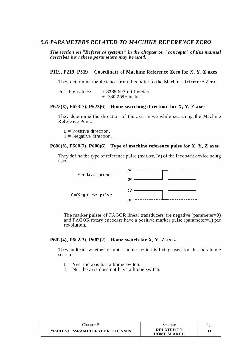
PageChapter: 5 Section:
MACHINE PARAMETERS FOR THE AXES 11
5.6 PARAMETERS RELATED TO MACHINE REFERENCE ZERO
The section on "Reference systems" in the chapter on "concepts" of this manualdescribes how these parameters may be used.
P119, P219, P319 Coordinate of Machine Reference Zero for X, Y, Z axes
They determine the distance from this point to the Machine Reference Zero.
Possible values: ± 8388.607 millimeters. ± 330.2599 inches.
P623(8), P623(7), P623(6) Home searching direction for X, Y, Z axes
They determine the direction of the axis move while searching the MachineReference Point.
0 = Positive direction.1 = Negative direction.
P600(8), P600(7), P600(6) Type of machine reference pulse for X, Y, Z axes
They define the type of reference pulse (marker, Io) of the feedback device beingused.
The marker pulses of FAGOR linear transducers are negative (parameter=0)and FAGOR rotary encoders have a positive marker pulse (parameter=1) perrevolution.
P602(4), P602(3), P602(2) Home switch for X, Y, Z axes
They indicate whether or not a home switch is being used for the axis homesearch.
0 = Yes, the axis has a home switch.1 = No, the axis does not have a home switch.
RELATED TOHOME SEARCH

Section:Chapter: 5Page
MACHINE PARAMETERS FOR THE AXES12
P112, P212, P312 1st home searching feedrate for X, Y, Z axesP810, P811, P812 2nd home searching feedrate for X, Y, Z axes
They determine the feedrates used during home search.
The axis will move at the 1st feedrate until the home switch is pressed and, then,at the 2nd feedrate until the marker pulse is found on the feedback device.
Possible values: 1 thru 65,535 mm./minute1 thru 25,800 0.1inch/minute.
When setting the 2nd feedrate to "0", the axis will move at 100 mm/min. (about4 inches/min).
P611(2) Home search required on power-up
It determines whether it is required or not to perform the home search on all theaxes after powering the CNC up.
0 = It is not required.1 = It is required.
Being this parameter set to "1", the CNC will issue the corresponding error messagewhen attempting to execute a part-program in AUTOMATIC, SINGLE BLOCKor TEACH-IN mode.
P804 Jogging feedrate prior to referencing (homing) the axes of the machine
This parameter is used when "P611(2)=1", thus being mandatory to home all theaxes after machine power-up.
It indicates the feedrate being applied when moving the axes with the Jog keysand the handwheels if the axes have not been referenced (homed) yet.
Possible values: 1 thru 65,535 mm./minute1 thru 25,800 0.1inch/minute.
P606(4) The home search generates an M30
It indicates whether the CNC generates an M30 automatically when executingthe axes homing function.
0 = M30 is not generated.1 = M30 is generated.
RELACIONADOS CON LAREFERENCIA MAQUINA

PageChapter: 5 Section:
MACHINE PARAMETERS FOR THE AXES 13
5.7 PARAMETERS FOR ACCELERATION/DECELERATION OFTHE AXES
The section on "Gain adjustment " in the chapter on "concepts" of this manualdescribes how these parameters may be used.
5.7.1 LINEAR ACCELERATION/DECELERATION
This type of acc./dec. is applied mainly on G00 and F00 moves although it is alsopossible to use it in G01 moves.
P721, P722, P723 ACC./DEC. Control of the X,Y, Z axes.
In order to avoid abrupt start-ups and brakes of the machine, it is possible todefine some acceleration and deceleration ramps.
These parameters define the time that each axis needs to reach the positioningfeedrate (machine parameters P111, P211, P311) while accelerating. Thisacceleration time will be the same as the deceleration time.
It is given by an integer between 0 and 255.
Value of 0 = There is no Acceleration/deceleration control.Value of 1 = 0.020 seconds.Value of 10 = 0.200 seconds. (10 x 0.02)Value of 255 = 5.100 seconds. (255 x 0.02)
During a linear interpolation G01 at F0, the CNC applies the longest of theacc./dec. times assigned to the axes involved in the move.
Note: No acc./dec. will be applied on circular interpolations (G02, G03).
P613(7) ACC./DEC. in all linear interpolations (G01).
It indicates whether the acc./dec. ramps (P721, P722, P723) are to be applied onall linear interpolations or only when they are carried out at the maximum feedrateset by machine parameters P110, P210, P310.
0 = Acc./Dec. applied only in linear interpolations at maximum feedrate.1 = Acc./Dec. applied in all linear interpolation (at any feedrate).
ACCELERATIONDECELERATION

Section:Chapter: 5Page
MACHINE PARAMETERS FOR THE AXES14
P620(2) Acceleration/deceleration in G05 (corner rounding)
It indicates whether or not the acc./dec. ramps are applied in blocks with G05active (corner rounding).
0 = Yes. Acc./dec. is being applied.1 = No. Acc./dec. is not being applied.
5.7.2 BELL-SHAPED ACCELERATION/DECELERATION
This type of acceleration may be applied on all kinds of movements, G00, G01,G02, etc and for any type of feedrate F.
P624(8) Bell-shaped acceleration/deceleration
It is to be used on high-speed machines.
The acc./dec. ramps are applied onto all kinds of movement: rapid, linearinterpolation, arcs, etc.
0 = No. This type of acc./dec. is not applied.1 = Yes. This type of acc./dec. is applied.
This parameter cancels the other acc./dec. parameters: P721, P722, P723, P724,P728 and P613(7).
Note that the acc./dec. ramps set by this parameter and P744 is common to allthe axes.
P744 Duration of the Bell-shaped Acc./Dec. ramp
This parameter will be used when machine parameter “P624(8)=1”.
It defines the time needed by the axis to reach the selected feedrate (whenaccelerating). This time period is the same for the deceleration stage and commonto all the axes of the machine.
It is given by an integer between 0 and 255.
Value of 0 = There is no Acc./Dec. common to all the axesValue of 1 = 0.010 seconds.Value of 10 = 0.100 seconds. (10 x 0.01)Value of 255 = 2.550 seconds. (255 x 0.01)
ACCELERATIONDECELERATION

PageChapter: 5 Section:
MACHINE PARAMETERS FOR THE AXES 15ACCELERATIONDECELERATION
5.7.3 FEED-FORWARD GAIN
P732, P733, P734 FEED-FORWARD gain for X, Y, Z axes.
With the Feed-forward gain, which is proportional to the feedrate, it is possibleto improve the positioning loop minimizing the amount of following error.However it is not recommended when acceleration/deceleration ramps arenot being used.
These parameters define the % of analog voltage due to the programmed feedrate.It is given by an integer between 0 and 255.
The value which will be added to the following error is (Kf x F/6) where F is theprogrammed feedrate and Kf is:
* The value of this parameter in the case of linear acc/dec.For example, for the X axis: "Kf = P732"
* An eighth of the value assigned to this parameter in the case of bell-shapedacceleration/deceleration.For example, for the X axis: "Kf = P732/8"
The CNC will apply the proportional gain (K1 and K2) to the value resultingfrom the addition of the following error plus the value selected by means of thefeed-Forward gain.
When the value resulting from the addition is smaller than the value assigned tothe gain break-point, the CNC will apply the following formula:
Analog = K1 x [Following error + (Kf x F/6)]
And when the value resulting from the addition is greater than the value of thegain break-point:
Analog = (K1 x Ep) + {K2 x [Following error + (Kf x F/6) - Ep]}
Where “Ep” is the gain break-point value assigned to the corresponding parameter.

Section:Chapter: 5Page
MACHINE PARAMETERS FOR THE AXES16
5.8 LEADSCREW RELATED PARAMETERS
With this CNC it is possible to compensate for leadscrew error as well as for itsbacklash when reversing movement direction.
5.8.1 LEADSCREW BACKLASH
P109, P209, P309 Backlash compensation for X, Y, Z axes
They indicate the amount of leadscrew backlash. When using linear transducers(scales), the corresponding parameter must be set to "0".
It is given in microns regardless of the work units being used.
Possible values: 0 thru 255 microns.
P624(1), P624(2), P624(3) Sign of the backlash for X, Y, Z axes
They define the sign of the backlash compensation value indicated by parametersP109, P209, P309.
0 = Positive.1 = Negative.
P113, P213, P313 Additional analog pulse for X, Y, Z axes
Additional analog pulse to make up for the leadscrew backlash when reversingmovement direction.
It is given by an integer between 0 and 255.
Value 0 = There is no additional analog pulse.Value 1 = 2.5 mV.Value 10 = 25.0 mV. (10 x 2.5)Value 255 = 637.5 mV. (255 x 2.5)
Every time the axis moving direction is reversed, the CNC will apply thecorresponding analog voltage for that axis plus the additional analog pulseindicated in this parameter during 40 milliseconds.
When the feedback device is a rotary encoder, this parameter must be set to "0".
LEADSCREW RELATED

PageChapter: 5 Section:
MACHINE PARAMETERS FOR THE AXES 17
5.8.2 LEADSCREW ERROR
There is a 30-point leadscrew compensation table for each axis.
For each point, it is required to define the position of the axis and the amount oferror at that point.
To access these tables, press the following keystroke sequence:
[AUX] (SPECIAL FUNCTIONS)[5] (AUXILIARY MODES)[1] (SPECIAL MODES)[0] [1] [0] [1] (ACCESS CODE)[3] (LEADSCREW ERROR COMPENSATION)
The operator may view the following or previous pages by using the up and downarrow keys.
To view a particular parameter, key in its number and press [RECALL]. The CNCwill show the page corresponding to that parameter.
To clear the table by setting all the parameters to 0, key in the following sequence:[F] [S] [P] [ENTER].
Each parameter pair of this table represents:
Even parameter The position of the error point on the leadscrew. This position isreferred to Machine Reference Zero (home).
Value range: ±8388.607 millimeters±330.2599 inches
Odd parameter The amount of leadscrew error at that point.
Value range: ±32.766 millimeters±1.2900 inches
When defining the compensation points on the table, the following rules must beobserved:
* The even parameters are ordered according to their position along the axis. Thefirst pair of parameters (P0 or P60) must be set for the most negative (least positive)point of the axis to be compensated.
* If all 30 points of the table are not required, set the unused ones to 0.
* For those sections outside the compensation area, the CNC will apply thecompensation defined for the nearest point.
* The Machine Reference Zero point (home) must be set with an error of 0.
* The maximum difference between the error values of two consecutivecompensation points must be within: ±0.127 mm (±0.0050 inches)
* The inclination of the error graph between two consecutive points cannot begreater than 3%.
LEADSCREW RELATED

Section:Chapter: 5Page
MACHINE PARAMETERS FOR THE AXES18
Examples: If the distance between two consecutive points is 3 mm. the maximumdifference of their relevant error values can be 0.090 mm.If the error difference between two consecutive points is the maximum(0.127mm), the distance between them cannot be smaller than4.233mm.
To EDIT a parameter, key in its number, press [=], key in the desired value and press[ENTER] so the new value is entered on the table.
Remember to press [RESET] or power the CNC off and back on once the machineparameters have been set in order for the CNC to assume their new values.
Programming example:
An X axis leadscrew is to be compensated according to the following graph inthe section between X-20 and X160:
Considering that the machine reference point has a value of X30 (meaning thatit is located 30mm from the Machine Reference Zero ), the leadscrew errorcompensation parameters will be defined as follows:
P000 = X -20.000 P001 = X 0.001P002 = X 0.000 P003 = X -0.001P004 = X 30.000 P005 = X 0.000P006 = X 60.000 P007 = X 0.002P008 = X 90.000 P009 = X 0.001P010 = X 130.000 P011 = X -0.002P012 = X 160.000 P013 = X -0.003P014 = X 0.000 P015 = X 0.000P016 = X 0.000 P017 = X 0.000
" " " "" " " "
P056 = X 0.000 P057 = X 0.000P058 = X 0.000 P059 = X 0.000
P606(8), P606(7), P606(6) Leadscrew error compensation for X, Y, Z
They indicate whether the CNC must apply leadscrew error compensation onthe corresponding axis or not.
0 = Leadscrew error compensation not applied.1 = Leadscrew error compensation applied.
LEADSCREW RELATED

PageChapter: 5 Section:
MACHINE PARAMETERS FOR THE AXES 19
5.9 SPECIAL MACHINE PARAMETERS
P609(1) Machine travels over 8388.607 mm (330.2599 inches)
This parameter must only be set for those machine having one or more axes witha travel greater than 8388.607 mm (330.2599 inches).
This parameter affects both axes even when one of them might not require thisextended travel.
Possible values:
0 = Machine with normal axis travel within 8388.607 mm (330.2599 inches).1 = Machine with extended axis travel over 8388.607 mm (330.2599 inches)
When setting this parameter to “1”, the following items must be considered:
* The minimum display resolution for both axes will now be: 0.01mm or0.001 inch.
* The programming format will now be: ±5.2 in mm and ±4.3 in inches.
* The minimum moving distance will now be: ±0.01mm and ±0.001 inch.The maximum moving distance will be: ±83886.07mm and ±3302.599 inches.
* The tool table format will be affected the same way:
R,L ±4.2 in mm or ±3.3 in inches. Minimum value: ±0.01mm and ±0.001inch. Maximum value: ±9999.99mm and ±393.699 inches.
I,K ±3.2 in mm and ±2.3 in inches. Minimum value: ±0.01mm and ±0.001inch. Maximum value: ±327.66 mm and ±12.900 inches.
* The integer values assigned to machine parameters P103, P203 and P303 foraxis resolution now acquire new units:
1 = 0.01 mm or 0.001 inch resolution.2 = 0.02 mm or 0.002 inch resolution.5 = 0.05 mm or 0.005 inch resolution.
10 = 0.10 mm or 0.010 inch resolution.
* To calculate K1 and K2 and the Feed-forward gain, the following error isnow expressed in 0.01 mm units (not microns) and 0.001 inch units (insteadof 0.0001 inch as before).
The maximum amount of following error permissible is now: 320mm
That is to say that K1 and K2 gains (parameters P114, P214, P314, P116,P216, P316) must be given in "mV/0.01mm (mV/0.001 inches).
* Machine parameters P115, P215 and P315 for gain break-point are nowexpressed in 0.01 units (not microns) and 0.001 inch units (instead of 0.0001inch as before).
SPECIAL

Section:Chapter: 5Page
MACHINE PARAMETERS FOR THE AXES20
* Machine parameters P109, P209, P309 (leadscrew backlash) and P118, P218,P318 (in-position zone) will also be given in 0.01 mm and 0.001 inch units.
P118 = 100 means an in-position zone of 1mm (or 0.1 inch) for the X axis.
* Machine parameters P112, P212, P312, P810, P811, P812 (homing feedrate)and P801 (unidirectional approach) will also be expressed in 0.01mm/min. or0.001 inch/min.
P112 = 10000 assigns a feedrate of 100m/min.
Examples to calculate resolution with P609(1)=1:
Example 1: Resolution in “mm” with square-wave encoder
We want to obtain a 0.01mm resolution with a square-wave encoder mounted on the X axiswhose leadscrew has a 5mm/turn pitch.
Since the multiplying factor applied by the CNC may be either x2 or x4 (depending on machineparameter setting). The resulting encoder line count will be:
Leadscrew pitchNumber of pulses =
Multiplying Factor x ResolutionFor a factor of x4:
5 mmNumber of pulses = = 125 pulses/rev.
4 x 0.01m
P103= 1 P604(4)=0 P106=0 P604(8)=0
For a factor of x2:5mm
Number of pulses = = 250 pulses/rev.2 x 0.01 mm
P103= 1 P604(4)=0 P106=0 P604(8)=1
Example 2: Resolution in “inches” with square-wave encoder
We would like to obtain a 0.001 inch resolution with a square-wave encoder mounted on to theX axis which has a 4-pitch leadscrew (4 turns per inch or 0.25 inch/turn).
Since the CNC always applies a multiplying factor of either x2 or x4 (selected by machineparameter), the required encoder line count (pulses per rev) in each case will be:
Leadscrew pitchNumber of pulses =
Multiplying factor x ResolutionWith a x4 factor:
0.25Number of pulses = = 62.5* pulses/turn
4 x 0.001* A gear reduction will be required to achieve this line count per turn.
P103= 1 P604(4)=1 P106=0 P604(8)=1
With a x2 factor:0.25
Number of pulses = = 125 pulses/turn2 x 0.001
P103= 1 P604(4)=1 P106=0 P604(8)=1
SPECIAL

PageChapter: 5 Section:
MACHINE PARAMETERS FOR THE AXES 21
P617(6) Axis resolution of 0.0001mm (tenth of a micron) or 0.00001 inch(10 millionths)
This parameter must only be set for those machine having one or more axesrequiring this kind of resolution.
This parameter affects both axes even when one of them might not require thiskind of resolution.
Possible values:
0 = Machine with normal axes with 0.001 mm or 0.0001 inch minimum resolution.
1 = Machine with special 0.0001mm or 0.00001 inch resolution.
When setting this parameter to “1”, the following items must be considered:
* The programming format will now be: ±3.4 in mm and ±2.5 in inches.
* The minimum moving distance will now be: ±0.0001mm and ±0.00001 inch.The maximum moving distance will be: ±838.8607mm and ±33.02599 inches.
* The tool table format will be affected the same way:
R,L ±2.4 in mm or ±1.5 in inches. Minimum value: ±0.0001mm and ±0.00001inch. Maximum value: ±99.9999mm and ±3.93699 inches.
I,K ±1.4 in mm and ±0.5 in inches. Minimum value: ±0.0001mm and±0.00001 inch. Maximum value: ±3.2766 mm and ±0.12900 inches.
* The integer values assigned to machine parameters P103, P203 and P303 foraxis resolution now acquire new units:
1 = 0.0001 mm, 0.00001 inch resolution.2 = 0.0002 mm, 0.00002 inch resolution.5 = 0.0005 mm, 0.00005 inch resolution.
10 = 0.0010 mm, 0.00010 inch resolution.
* When calculating K1, K2 gains and the Feed-forward gain, the following erroris now expressed in 0.0001 mm units (not microns) and 0.00001 inch units(instead of 0.0001 inch as before). The maximum amount of following errorallowed is now: 3.20mm
That is to say that K1 and K2 gains (parameters P114, P214, P314, P116,P216, P316) must be given in "mV/0.0001mm (mV/0.00001 inches).
* Machine parameters P115, P215, P315 for gain break-point are now expressedin 0.0001 units (not microns) and 0.00001 inch units (instead of 0.0001 inchas before).
* Machine parameters P109, P209, P309 (leadscrew backlash) and P118, P218,P318 (in-position zone) will also be given in 0.0001 mm and 0.00001 inchunits.
P118 = 100 means an in-position zone of 0.01mm (or 0.001 inch) for the Xaxis.
SPECIAL
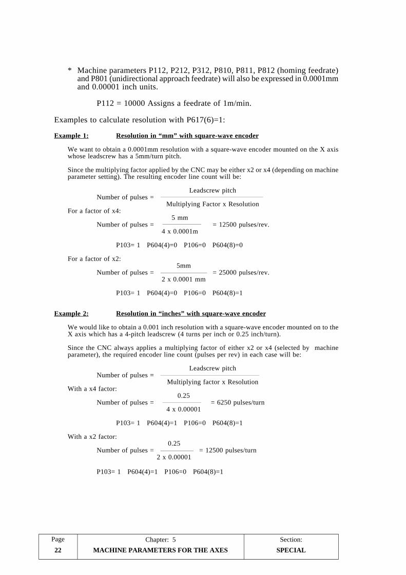
Section:Chapter: 5Page
MACHINE PARAMETERS FOR THE AXES22
* Machine parameters P112, P212, P312, P810, P811, P812 (homing feedrate)and P801 (unidirectional approach feedrate) will also be expressed in 0.0001mmand 0.00001 inch units.
P112 = 10000 Assigns a feedrate of 1m/min.
Examples to calculate resolution with P617(6)=1:
Example 1: Resolution in “mm” with square-wave encoder
We want to obtain a 0.0001mm resolution with a square-wave encoder mounted on the X axiswhose leadscrew has a 5mm/turn pitch.
Since the multiplying factor applied by the CNC may be either x2 or x4 (depending on machineparameter setting). The resulting encoder line count will be:
Leadscrew pitchNumber of pulses =
Multiplying Factor x ResolutionFor a factor of x4:
5 mmNumber of pulses = = 12500 pulses/rev.
4 x 0.0001m
P103= 1 P604(4)=0 P106=0 P604(8)=0
For a factor of x2:5mm
Number of pulses = = 25000 pulses/rev.2 x 0.0001 mm
P103= 1 P604(4)=0 P106=0 P604(8)=1
Example 2: Resolution in “inches” with square-wave encoder
We would like to obtain a 0.001 inch resolution with a square-wave encoder mounted on to theX axis which has a 4-pitch leadscrew (4 turns per inch or 0.25 inch/turn).
Since the CNC always applies a multiplying factor of either x2 or x4 (selected by machineparameter), the required encoder line count (pulses per rev) in each case will be:
Leadscrew pitchNumber of pulses =
Multiplying factor x ResolutionWith a x4 factor:
0.25Number of pulses = = 6250 pulses/turn
4 x 0.00001
P103= 1 P604(4)=1 P106=0 P604(8)=1
With a x2 factor:0.25
Number of pulses = = 12500 pulses/turn2 x 0.00001
P103= 1 P604(4)=1 P106=0 P604(8)=1
SPECIAL

PageChapter: 5 Section:
MACHINE PARAMETERS FOR THE AXES 23SPECIAL
P908, P909 Collision zone between Y, Z
These parameters are used mainly on boring mills and horizontal machining centersto define a possible collision zone between the Y and Z axes.
Each one of them indicates the position value where the collision zone begins.
P908 = Y axis position value.P909 = Z axis position value.
These position values are absolute and referred to the machine reference zero(home).
Possible values: ± 8388.607 millimeters. ± 330.2599 inches.
If one of the axes gets into this zone, the CNC will prevent the other one fromgetting into it.

PageChapter: 6 Section:
SPINDLE MACHINE PARAMETERS 1
6. SPINDLE MACHINE PARAMETERS
6.1 PARAMETERS RELATED TO SPINDLE SPEED RANGE CHANGE
The section on "Spindle range change" in the chapter on "concepts" of this manualdescribes how these parameters may be used.
P7, P8, P9, P10 Maximum spindle speed for 1st, 2nd, 3rd and 4th RANGE.
They indicate the maximum spindle speed assigned to each range.
It is given in revolutions per minute and they accept any integer value between 0 and9999.
The value assigned to P7 must correspond to the lowest range and that of P10 to thehighest range. When not all the ranges are being used, assign the lowest range to P7and set the unused ones to the highest speed value.
P601(6) Residual analog voltage (S) during spindle range change.
It determines whether the CNC must generate a residual analog voltage (S) during arange change.
Possible values:
0 = No residual analog voltage is generated.1 = A residual analog voltage is generated.
P706 Value of the residual analog voltage (S).
It indicates the value of the residual analog voltage (S) for the spindle speed rangechange.
It is given by an integer between 1 and 255.
Value of 1 = 2.5 mV.Value of 10 = 25.0 mV. (10 x 2.5)Value of 255 = 637.5 mV. (255 x 2.5)
P707 Oscillation period during a spindle range change.
It indicates the oscillation time period during a spindle range change.
It is given by an integer between 0 and 255.
Value of 0 = Continuous movement in one direction.Value of 1 = Continuous movement in the other direction.Value of 2 = 20 msec. oscillation period.Value of 10 = 100 msec. oscillation period.Value of 255 = 2550 msec. oscillation period.
RELATED TORANGE CHANGE
Section:Chapter: 6Page
SPINDLE MACHINE PARAMETERS2
6.2 PARAMETERS FOR ANALOG SPINDLE SPEED OUTPUT
The section on "Spindle" in the chapter on "concepts" of this manual describes howthese parameters may be used.
P601(4) Sign of the spindle analog output.
It determines the sign of the spindle analog output (S). If correct, leave it as is; if not,change it.
Possible values: “0” and “1”.
P610(4) Unipolar or bipolar spindle analog output.
It indicates the type of spindle analog output.
If the analog output is BIPOLAR, the CNC will generate a positive analog voltage (0to +10V) to turn the spindle clockwise (M03) and a negative analog voltage (0 to -10V) to turn the spindle counter-clockwise (M04).
If the analog output is UNIPOLAR, the CNC will generate a positive analog voltage(0 to +10V) for either turning direction.
0 = The output must be BIPOLAR.1 = The output must be UNIPOLAR.
Bear in mind that with machine parameter P601(4) it is possible to change the signof the analog output and, therefore, the spindle turning direction.
P609(4) Any spindle speed change generates an S STROBE
It indicates whether or not a 200msec. S STROBE (pulse) is output at pin 3 ofconnector I/O1, every time a new spindle speed is selected.
0 = No S STROBE is generated.1 = An S STROBE is generated.
FOR THE ANALOG OUTPUT

PageChapter: 6 Section:
SPINDLE MACHINE PARAMETERS 3
6.3 PARAMETERS FOR SPINDLE SPEED OUTPUT IN BCD
The section on "Spindle" in the chapter on "concepts" of this manual describes howthese parameters may be used.
P601(3) Spindle speed output in 2-digit BCD code.
It indicates whether there is a 2-digit BCD coded spindle speed output or not. If not,the CNC will output an analog voltage for the spindle.
0 = No 2-digit BCD coded output is used for spindle speed.1 = A 2-digit BCD coded output is used for spindle speed.
If this parameter is set to “1”, the CNC will issue the value corresponding to theprogrammed spindle speed via the BCD outputs which are pins 20 thru 27 of the I/O1 connector. It will also output an S STROBE pulse at pin 3 of connectorI/O 1.
The chart below shows the BCD code corresponding to the programmable spindlespeed values:
If a value greater than 9999 is programmed, the CNC will assume the spindle speedcorresponding to 9999.
ProgrammedS S BCD Programmed
S S BCD ProgrammedS S BCD Programmed
S S BCD
0 S 00 25-27 S 48 200-223 S 66 1600-1799 S 84
1 S 20 28-31 S 49 224-249 S 67 1800-1999 S 85
2 S 26 32-35 S 50 250-279 S 68 2000-2239 S 86
3 S 29 36-39 S 51 280-314 S 69 2240-2499 S 87
4 S 32 40-44 S 52 315-354 S 70 2500-2799 S 88
5 S 34 45-49 S 53 355-399 S 71 2800-3149 S 89
6 S 35 50-55 S 54 400-449 S 72 3150-3549 S 90
7 S 36 56-62 S 55 450-499 S 73 3550-3999 S 91
8 S 38 63-70 S 56 500-559 S 74 4000-4499 S 92
9 S 39 71-79 S 57 560-629 S 75 4500-4999 S 93
10-11 S 40 80-89 S 58 630-709 S 76 5000-5599 S 94
12 S 41 90-99 S 59 710-799 S 77 5600-6299 S 95
13 S 42 100-111 S 60 800-899 S 78 6300-7099 S 96
14-15 S 43 112-124 S 61 900-999 S 79 7100-7999 S 97
16-17 S 44 125-139 S 62 1000-1119 S 80 8000-8999 S 98
18-19 S 45 140-159 S 63 1120-1249 S 81 9000-9999 S 99
20-22 S 46 160-179 S 64 1250-1399 S 82
23-24 S 47 180-199 S 65 1400-1599 S 83
FOR BCD OUTPUT

Section:Chapter: 6Page
SPINDLE MACHINE PARAMETERS4
P601(2) 4-digit BCD coded spindle speed output
It indicates whether there is a 4-digit BCD coded spindle speed output or not. If not,the CNC will output an analog voltage for the spindle.
0 = No 4-digit BCD coded output is used for spindle speed.1 = A 4-digit BCD coded output is used for spindle speed.
If this parameter is set to “1”, the CNC will issue the value corresponding to theprogrammed spindle speed via the BCD outputs which are pins 20 thru 27 of the I/O1 connector.
The CNC will output the value corresponding to the programmed S in two stages witha 100 msec. delay between them. It will also output an S STROBE pulse at pin 3 ofconnector I/O 1.
Pin 1st stage 2nd stage
2021 Thousands Tens2223
2425 Hundreds Units2627
FOR BCD OUTPUT

PageChapter: 7 Section:
CONCEPTS 1
7. CONCEPTS
Atention:
It is recommended to save the CNC machine parameters onto a peripheraldevice or PC to avoid losing them by mistake or any malfunction.
7.1 FEEDBACK SYSTEMS
The feedback inputs of this CNC are:
Connector A1.
They are used to connect the feedback for the X axis.
It admits sine-wave and double-ended (differential) square-wave signals whichmust be properly indicated by machine parameters “P106" and the two dip-switches located under the feedback input.
Connector A2.
They are used to connect the feedback for the Y axis.
It admits sine-wave and double-ended (differential) square-wave signals whichmust be properly indicated by machine parameters “P206" and the two dip-switches located under the feedback input.
Connector A3.
They are used to connect the feedback for the Z axis.
It admits sine-wave and double-ended (differential) square-wave signals whichmust be properly indicated by machine parameters “P306" and the two dip-switches located under the feedback input.
Connector A4.
It is used to connect the electronic handwheel associated with the Y axis.
Set the two dip-switches, located under the feedback input, accordingly.
Connector A5.
It is used to connect the electronic handwheel associated with the Z axis.
Set the two dip-switches, located under the feedback input, accordingly.
Connector A6.
It is used to connect the electronic handwheel associated with the X axis.
FEEDBACK SYSTEMS

Section:Chapter: 7Page
CONCEPTS2
7.1.1 COUNTING FREQUENCY LIMITS
Sine-wave signals
The maximum counting frequency for sine-wave feedback signals is 25KHz (25,000pulses/sec.).
Therefore, the maximum feedrate for each axis will depend upon the selectedresolution (machine parameters “P103, P203, P303”) and the period of the feedbacksignal being used.
Example 1:
When using a linear scale with a 20µm, the maximum feedrate for an axiswith 1µm resolution will be:
20 µm/pulse x 25,000 pulses/sec = 500 mm/sec = 30 m/min.
Square-wave signals
The maximum counting frequency for differential square-wave signals is200 KHz (200,000 pulses/sec.), with a 450nsec. separation between A and Bflanks (that is 90º ±20º phase shift).
Therefore, the maximum feedrate for each linear axis will depend upon the selectedresolution (machine parameters “P103, P203, P303”) and the period of the feedbacksignal being used.
When using FAGOR linear scales, the maximum feedrate is limited by its owncharacteristics to 60m/min (2362 inches/min).
When using FAGOR rotary encoders, the limitation is set by the maximum numberof pulses delivered by the encoder; which is 200KHz.
FEEDBACK SYSTEMS

PageChapter: 7 Section:
CONCEPTS 3
7.2 MOVEMENT BY ELECTRONIC HANDWHEEL
This CNC may have up to 3 electronic handwheels associated to their axes (one pereach axis, X, Y, Z). They can be set by machine parameter.
These handwheels will be active in the JOG mode when the feedrate override switch(F.O.S) on the operator panel is set at any position indicated by the symbol.
The handwheel positions available at the F.O.S. are 1, 10 and 100 which indicate themultiplication factor applied to the handwheel pulses.
This way, the actual axis movement results from multiplying the handwheel pulsesby the selected factor.
Those units correspond to the display units being selected.
Example:
Handwheel line count: 250 pulses per turn
F.O.S. position Distance moved per turn
1 0.250 mm or 0.0250 inch10 2.500 mm or 0.2500 inch
100 25.000 mm or 2.5000 inches
The feedback connectors to be used for each axis and each handwheel are:
A6 for the X axis handwheelA4 for the Y axis handwheelA5 for the Z axis handwheel
When using only the FAGOR 100P handwheel with axis selector button, it must beconnected to A6.
HANDWHEEL MOVEMENT

Section:Chapter: 7Page
CONCEPTS4
7.3 AXIS RESOLUTION
The CNC has a series of machine parameters to set the resolution of each axis.
The resolution used on each axis indicates the minimum variation distinguishableby the feedback device. It is given in microns or 0.0001 inch units.
The machine parameters used to define the axis resolution are the following:
P103, P203, P303 They set the counting resolution for each axis.
P604(4), P604(3), P604(2) They set the measuring units for each axis feedbacksignal (mm or inches).
P106, P206, P306 They set the type of feedback signal being used(square-wave or sine-wave) for each axis.
P604(8), P604(7), P604(6) They indicate the multiplying factor, x2 or x4 to beapplied to the feedback signals of each axis.
P622(1), P622(2), P622(3) They indicate the special multiplying factor to beapplied to the sine-wave feedback signals of eachaxis (besides the normal x5).
AXIS RESOLUTION

PageChapter: 7 Section:
CONCEPTS 5
Example 1: Resolution in “mm” with square-wave encoder
We want to obtain a 2µm resolution with a square-wave encoder mounted on theX axis whose leadscrew has a 5mm/turn pitch.
Since the multiplying factor applied by the CNC may be either x2 or x4 (dependingon machine parameter setting). The resulting encoder line count will be:
Leadscrew pitchNumber of pulses =
Multiplying Factor x ResolutionFor a factor of x4:
5000 µmNumber of pulses = = 625 pulses/rev.
4 x 2 µm
P103= 2 P604(4)=0 P106=0 P604(8)=0
For a factor of x2:5000 µm
Number of pulses = = 1250 pulses/rev.2 x 2 µm
P103= 2 P604(4)=0 P106=0 P604(8)=1
If a FAGOR encoder is chosen, its pulse output frequency is limited to 200KHz(although the CNC admits square-wave pulses with a frequency of up to 200KHz).Therefore, the maximum feedrate for this axis will be:
When using a x4 multiplying factor:
200,000 pulses/sec.Max. Feed = x 5 mm/rev. = 1600 mm/sec. = 96 m/min.
625 pulses/rev.
When using a x2 multiplying factor:
200,000 pulses/sec.Max. Feed = x 5 mm/rev. = 800 mm/sec. = 48 m/min.
1250 pulses/rev.
AXIS RESOLUTION

Section:Chapter: 7Page
CONCEPTS6
Example 2: Resolution in “mm” with sine-wave encoder
We would like to get a 2µm resolution with a sine-wave encoder mounted on tothe X axis which has a 5mm/turn leadscrew pitch.
We have the following options:
Since the CNC always applies a x5 multiplying factor to the sine-wave feedbacksignals, we will need an encoder:
Leadscrew pitchNº of pulses =
5 x Multiplying factor x Resolution
For P604(8)=1 (x2)
5000µm/turnNº pulses = = 250 pulses/turn
5 x 2 x 2µm/pulse
Therefore:
If P622(1)=0 => P604(4)=0 P106=1 P604(8)=1 P103= 10If P622(1)=1 => P604(4)=0 P106=1 P604(8)=1 P103= 2
For P604(8)=0 (x4)
5000µm/turnNº pulses = = 125 pulses/turn
5 x 4 x 2µm/pulse
Therefore:
If P622(1)=0 => P604(4)=0 P106=1 P604(8)=0 P103= 5If P622(1)=1 => P604(4)=0 P106=1 P604(8)=0 P103= 2
Even when choosing a FAGOR encoder which outputs up to 200KHz, the actualusable frequency is this time limited by the CNC to 25KHz for sine-wave signals.Therefore, the maximum feedrate for this example will be:
25,000 pulses/sec.Max. Feed = x 5 mm/rev. = 1000 mm/sec. = 60 m/min.
125 pulses/rev.
and 30m/min for 250-line encoder.
AXIS RESOLUTION
P622(1)=0P604(8) Resolution P103=1 (x2) 2 microns 10=0 (x4) 2 microns 10
P622(1)=1P604(8) Resolution P103=1 (x2) 2 microns 2=0 (x4) 2 microns 2

PageChapter: 7 Section:
CONCEPTS 7
Example 3: Resolution in “mm” with square-wave linear scale
Considering that the CNC applies either a x2 or x4 multiplying factor (set bymachine parameter), a linear scale must be chosen whose pitch is 2 or 4 timesthe desired resolution.
When using FAGOR linear transducers (scales) with 20µm pitch, the followingresolutions may be obtained: 5µm (20/4), 10µm (20/2).
Thus:
Scale pitch P103 P604(4) P106 P604(8)
20µm 5 0 0 020µm 10 0 0 1
Since the counting frequency of the CNC is limited to 200KHz for square-wavesignals, the maximum feedrate obtainable with a 20µm-pitch scale is:
Max. Feed = 20 µm/pulse x 200,000 pulses/sec. = 4000 mm/sec. = 240 m/min.
However, if FAGOR linear scales are used, the maximum feedrate is limited(by the scales) to 60m/min. (2362 inches/min.)
Example 4: Resolution in “mm” with sine-wave linear scales
A sine-wave linear scale is being used with a 20µm pitch and 1µm resolution.
There are the following options:
Therefore:
If P622(1)=0 => P604(4)=0 P106=1 P604(8)=0 P103= 5If P622(1)=1 => P604(4)=0 P106=1 P604(8)=0 P103= 1
The CNC's counting frequency is limited to 25KHz (30m/min) for sine-wavesignals.
However, if FAGOR linear scales are used, the maximum feedrate is limited(by the scales) to 60m/min. (2362 inches/min.)
AXIS RESOLUTION
P622(1)=0P604(8) Resolution P103=0 (x4) 1 micron 5
P622(1)=1P604(8) Resolution P103=0 (x4) 1 micron 1

Section:Chapter: 7Page
CONCEPTS8
Example 5: Resolution in “inches” with square-wave encoder
We would like to obtain a 0.0001 inch resolution with a square-wave encodermounted on to the X axis which has a 4-pitch leadscrew (4 turns per inch or0.25 inch/turn).
Since the CNC always applies a multiplying factor of either x2 or x4 (selectedby machine parameter), the required encoder line count (pulses per rev) in eachcase will be:
Leadscrew pitchNumber of pulses =
Multiplying factor x Resolution
With a x4 factor:
0.25Number of pulses = = 625 pulses/turn
4 x 0.0001
P103= 1 P604(4)=1 P106=0 P604(8)=0
With a x2 factor:
0.25Number of pulses = = 1250 pulses/turn
2 x 0.0001
P103= 1 P604(4)=1 P106=0 P604(8)=1
If a FAGOR encoder is used, the counting frequency is limited to 200KHz bythe scale (the CNC admits up to 200KHz for square-wave signals). Therefore,the maximum feedrate for this axis will be:
For x4 multiplying factor:
200,000 pulses/sec.Max. Feed= x 0.25 inch/rev = 80 inches/sec= 4800 inch/min.
625 pulses/rev
For x2 multiplying factor:
200,000 pulses/sec.Max. Feed= x 0.25 inch/rev = 40 inches/sec= 2400 inch/min.
1250 pulses/rev
AXIS RESOLUTION

PageChapter: 7 Section:
CONCEPTS 9
Example 6: Resolution in “inches” with sine-wave encoder
We would like to get a 0.0001 inch resolution with a sine-wave encoder mountedon to the X axis which has a 4-pitch leadscrew (0.25 inch/turn).
We have the following options:
Since the CNC always applies a x5 multiplying factor to the sine-wave feedbacksignals, we will need an encoder:
Leadscrew pitchNº of pulses =
5 x Multiplying factor x Resolution
For P604(8)=1 (x2)
0.25 inch/turnNº pulses = = 250 pulses/turn
5 x 2 x 0.0001 inch/pulse
Therefore:
If P622(1)=0 => P604(4)=0 P106=1 P604(8)=1 P103= 5If P622(1)=1 => P604(4)=0 P106=1 P604(8)=1 P103= 1
For P604(8)=0 (x4)
0.25 inch/turnNº pulses = = 125 pulses/turn
5 x 4 x 0.0001 inch/pulse
Therefore:
If P622(1)=0 => P604(4)=0 P106=1 P604(8)=0 P103= 5If P622(1)=1 => P604(4)=0 P106=1 P604(8)=0 P103= 1
Even when choosing a FAGOR encoder which outputs up to 200KHz, the actualusable frequency is this time limited by the CNC to 25KHz for sine-wave signals.Therefore, the maximum feedrate for this example will be:
25,000 pul./sec.Max. Feed = x 0.25 inch/rev. = 500 inch/sec. = 3000 inch/min.
125 pul./rev.
and 1500 inch/min for 250-line encoder.
P622(1)=0P604(8) Resolution P103=1 (x2) 0.0001 inch 5=0 (x4) 0.0001 inch 5
P622(1)=1P604(8) Resolution P103=1 (x2) 0.0001 inch 1=0 (x4) 0.0001 inch 1
AXIS RESOLUTION

Section:Chapter: 7Page
CONCEPTS10
7.4 ADJUSTMENT OF THE AXES
In order to make this adjustment it is necessary to have the feedback systems for allthe axes connected to the CNC.
Before starting the adjustment of the axes, it is a good idea to move them close tothe middle of their travels placing the travel-limit switches (controlled by the electricalcabinet) close to these points in order to avoid any damage to the machine.
Verify that the axes are not CONTINUOUSLY CONTROLLED (that their enablesignal is cancelled once the axis is in position). To do this, machine parametersP105, P205 and P305 must be set to “0”.
Also, make sure that the CNC has been set to provide a delay between the axesenable and their analog voltage output. To do this, machine parameters P104, P204and P304 must be set to “1”.
After the machine parameters for the axes have been properly set, proceed with theiradjustment by following these suggestions:
* The axes should be adjusted one at a time.
* Connect the power output of the drive corresponding to the axis being adjusted.
* In the JOG mode, move the axis being adjusted.
In case of run-away, the CNC will display the relevant following error and themachine parameter corresponding to the SIGN OF THE ANALOG VOLTAGEwill have to be changed. Machine parameters P100, P200 and P300.
* If the axis does not run away; but the direction of the move is not the desiredone, the machine parameter corresponding to the COUNTING DIRECTION(P101, P201 and P301) will have to be changed as well as that correspondingto the SIGN OF THE ANALOG VOLTAGE (P100, P200 and P300).
* If the counting direction is correct but the axis moves in the opposite directionto the one indicated, change the axis machine parameter corresponding to themoving direction (P102, P202 and P302).
AXIS ADJUSTMENT

PageChapter: 7 Section:
CONCEPTS 11
7.4.1 ADJUSTMENT OF THE DRIFT (OFFSET) AND MAXIMUMFEEDRATE
These adjustments are performed on axis servo drives and spindle drives.
Drift adjustment (offset)
This adjustment will be made in two stages:
Preadjustment of the drive offset
* Disconnect the analog voltage input of the drive and short-circuit it witha wire jumper.
* Turn the offset potentiometer of the drive until the voltage on the tachoterminals is 0V. This should be checked on the 200 mV DC scale of thevolt-meter.
* Remove the wire jumper mentioned above.
Critical adjustment of the drive offset
* Move the axis continuously back and forth.
For example; Assign the maximum travel by using BEG X and END Xand execute the following commands:
The X axis will continuously move back and forth from BEGIN to ENDuntil is pressed
When single mode is selected (by means of the key), the keymust be pressed at the end of each move.
While the axis is moving, turn the offset potentiometer of the drive untilthe amounts of following error obtained in both directions are the same.
AXIS ADJUSTMENT
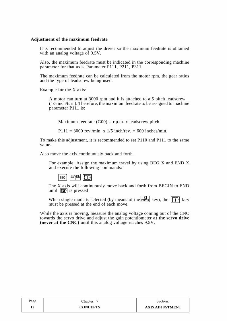
Section:Chapter: 7Page
CONCEPTS12
Adjustment of the maximum feedrate
It is recommended to adjust the drives so the maximum feedrate is obtainedwith an analog voltage of 9.5V.
Also, the maximum feedrate must be indicated in the corresponding machineparameter for that axis. Parameter P111, P211, P311.
The maximum feedrate can be calculated from the motor rpm, the gear ratiosand the type of leadscrew being used.
Example for the X axis:
A motor can turn at 3000 rpm and it is attached to a 5 pitch leadscrew(1/5 inch/turn). Therefore, the maximum feedrate to be assigned to machineparameter P111 is:
Maximum feedrate (G00) = r.p.m. x leadscrew pitch
P111 = 3000 rev./min. x 1/5 inch/rev. = 600 inches/min.
To make this adjustment, it is recommended to set P110 and P111 to the samevalue.
Also move the axis continuously back and forth.
For example; Assign the maximum travel by using BEG X and END Xand execute the following commands:
The X axis will continuously move back and forth from BEGIN to ENDuntil is pressed
When single mode is selected (by means of the key), the keymust be pressed at the end of each move.
While the axis is moving, measure the analog voltage coming out of the CNCtowards the servo drive and adjust the gain potentiometer at the servo drive(never at the CNC) until this analog voltage reaches 9.5V.
AXIS ADJUSTMENT

PageChapter: 7 Section:
CONCEPTS 13
7.4.2 GAIN ADJUSTMENT
It is necessary to properly adjust the different gains for each axis in order to optimizethe response of the whole system to the programmed movements.
It is recommended to use an oscilloscope in order to obtain a finer adjustment of theaxes by monitoring the signals provided by the tacho. The diagram on the leftcorresponds to the ideal signal shape and the other ones to an unstable start-up andbrake-down.
The CNC has a series of machine parameters which permit adjusting the proportionalgain for each axis. These parameters are:
PROPORTIONAL GAIN K1.
Defined by parameters: P114, P214, P314.
PROPORTIONAL GAIN K2.
Defined by parameters: P116, P216, P316.
Value of the GAIN BREAK POINT
Defined by parameters: P115, P215, P315.
FEED-FORWARD GAIN or gain proportional to the feedrate.
Defined by parameters: P732, P733, P734.
The parameters corresponding to the proportional gain K1 and K2 as well as for thegain break point allow adjusting the Proportional Gain for the axis.
The parameter for the Feed-Forward gain (proportional to feedrate) will be used whenacceleration/deceleration control is being applied onto the corresponding axis.
AXIS ADJUSTMENT

Section:Chapter: 7Page
CONCEPTS14
7.4.3 PROPORTIONAL GAIN ADJUSTMENT
The analog voltage supplied by the CNC to control the axis is, at all times, a functionof the amount of following error; that is, the difference between the theoretical positionand the real (actual) position of the axis.
Analog output = Proportional gain “K” x Following Error
On start-up and slow-down, the following error of the axis is very small. Therefore,the proportional gain must be great in order for the axis to respond properly.
On the other hand, once the axis reaches its programmed speed, the following erroris maintained practically constant and it is necessary to apply a smaller gain (K) inorder to keep the system stable.
The FAGOR 800M CNC offers two proportional gains K1 and K2 to better adjustthe system as well as another parameter referred to as Gain Break point which definesthe active area for each one of these gains.
The CNC applies the proportional gain K1 whenever the amount of following errorfor the axis is smaller than the value assigned to the machine parameter correspondingto the gain break-point.
When the amount of following error exceeds the gain break-point value, the CNCapplies the K2 value.
Analog = (K1 x Ep) + [K2 x (Following Error - Ep)]
Where “Ep” is the value assigned to the gain break-point and it is given inmicrons.
AXIS ADJUSTMENT

PageChapter: 7 Section:
CONCEPTS 15
When adjusting the proportional gain, it must be borne in mind that:
* When the amount of following error exceeds 32mm (1.2598 inches) the CNCwill issue a Following error message for the corresponding axis.
* The amount of following error will decrease as the gain value increases, but thesystem will tend to be more unstable.
* In practice, most machines seem to respond well to what is called a unity gain(or gain of 1) which represents a following error of 1mm at a feedrate or 1m/minute or a following error of 0.001 inch at a feedrate of 1 inch/min.
Therefore, this could be used as a practical starting point for the gain calculationdescribed next. After analyzing the behavior of the machine for this gain, itsvalue may be changed in order to optimize it.
AXIS ADJUSTMENT

Section:Chapter: 7Page
CONCEPTS16
7.4.3.1 CALCULATION OF K1, K2 AND GAIN BREAK-POINT
The value of K1 represents the analog voltage corresponding to 1 micron of followingerror. It is given by an integer between 0 and 255 in such a way that a value of 64corresponds to an analog voltage of 2.5mV.
Therefore, the K1 value corresponding to a gain of 1 and a maximum motor speedadjusted to 9.5V servo analog input would be given by the following formulae:
243.2In metric (FE= 1mm for F=1m/min): K1 =
Fmax in m/min (P111 for X)
9575In inches (FE= 0.001inch for F=1inch/min): K1 =
Fmax in inch/min (P111 for X)
For example:
If the top feedrate for an axis is 500 inches/min (P111 for X), the K1 correspondingto a unity gain would be: K1 = 9575/500 = 19.15 and the value assigned to thecorresponding parameter would be K1=19.
If the top feedrate for an axis is 20m/min, the K1 corresponding to a unity gainwould be: K1 = 243.2/20 = 12.16 and the value assigned to the correspondingparameter would be K1=12.
The amount of following error corresponding to the GAIN BREAK-POINT is givenin microns or 0.0001 inch units (by parameter P115 for the X axis, P215 for the Yaxis, etc.). It is recommended to set it to a value slightly greater than the followingerror corresponding to the maximum machining feedrate F0 (P110, P210, P310).
For example:
Let’s suppose that K1 has been set for a gain of 1 (not K1=1) and that the maximummachining feedrate is 150 inches/min (P110, P210, P310). At this feedrate, thefollowing error should be about 0.150 inch. Thus, the gain break-point valueshould be slightly larger than 0.150 inch; for example: P115=0.155 inch.
Or in metric:
Let’s suppose that K1 has been set for a gain of 1 (not K1=1) and that the maximummachining feedrate is 5 m/min (P110, P210, P310). At this feedrate, the followingerror should be about 5 mm. Thus, the gain break-point value should be slightlylarger than 5 mm; for example: P115=6 mm.
The machine parameter K2 gain sets the analog voltage for 1 micron of followingerror being applied from the gain break-point on.
It is also given by an integer between 0 and 255 and it is typically set to a valuebetween 50% and 70% of K1 in order to avoid abrupt analog voltage changes whenswitching to slow machining feedrates.
AXIS ADJUSTMENT
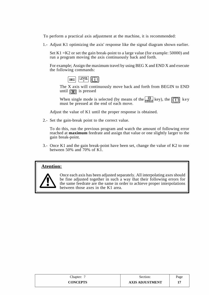
PageChapter: 7 Section:
CONCEPTS 17
To perform a practical axis adjustment at the machine, it is recommended:
1.- Adjust K1 optimizing the axis' response like the signal diagram shown earlier.
Set K1 =K2 or set the gain break-point to a large value (for example: 50000) andrun a program moving the axis continuously back and forth.
For example; Assign the maximum travel by using BEG X and END X and executethe following commands:
The X axis will continuously move back and forth from BEGIN to ENDuntil is pressed
When single mode is selected (by means of the key), the keymust be pressed at the end of each move.
Adjust the value of K1 until the proper response is obtained.
2.- Set the gain-break point to the correct value.
To do this, run the previous program and watch the amount of following errorreached at maximum feedrate and assign that value or one slightly larger to thegain break-point.
3.- Once K1 and the gain break-point have been set, change the value of K2 to onebetween 50% and 70% of K1.
Atention:
Once each axis has been adjusted separately. All interpolating axes shouldbe fine adjusted together in such a way that their following errors forthe same feedrate are the same in order to achieve proper interpolationsbetween those axes in the K1 area.
AXIS ADJUSTMENT

Section:Chapter: 7Page
CONCEPTS18
7.4.4 FEED-FORWARD GAIN ADJUSTMENT.
With the Feed-Forward gain it is possible to improve the positioning loop of theaxes, thus minimizing the amount of following error. This gain must be used onlywhen working with ACC/DEC.
This CNC offers two types of acc/dec.:
Linear
It is mainly applied onto G00 and F00 moves, although it may also be used inG01 moves.
Bell shape:
This type may be used on all kinds of movements, G00, G01, G02, etc. and withany type of feedrate F.
7.4.4.1 CALCULATION OF FEED-FORWARD GAIN
The Feed-Forward gain is proportional to the feedrate and is set by machine parametersP732, P733, P734 which indicate the % of analog voltage that is due to theprogrammed feedrate.
The value added to the following error is (Kf x F/6) where Kf is the value of Feed-Forward and F is the programmed feedrate.
The CNC will apply the proportional gain (K1 and K2) to the value resulting fromadding the following error of the machine plus the value selected by the Feed-Forward.
When the result of the addition is smaller than the value of the gain break-point, theCNC will apply the formula:
Analog = K1 x [Following Error + (Kf x F/6)]
And when the result of the addition is greater than the value of the gain break-point,the CNC will apply the formula:
Analog = (K1 x Ep) + {K2 x [Following Error + (Kf x F/6) - Ep]}
Where “Ep” is the value of the gain break-point.
AXIS ADJUSTMENT

PageChapter: 7 Section:
CONCEPTS 19
7.4.5 LEADSCREW ERROR COMPENSATION
With this CNC it is possible to compensate for leadscrew error as well as for itsbacklash when reversing movement direction.
There is a 30-point leadscrew error compensation table for each axis. To access thesetables, press the following keystroke sequence:
[AUX] (SPECIAL FUNCTIONS)[5] (AUXILIARY MODES)[1] (SPECIAL MODES)[0] [1] [0] [1] (ACCESS CODE)[3] (LEADSCREW ERROR COMPENSATION)
The operator may view the following or previous pages by using the up and downarrow keys.
To view a particular parameter, key in its number and press [RECALL]. The CNCwill show the page corresponding to that parameter.
To clear the table by setting all the parameters to 0, key in the following sequence:[F] [S] [P] [ENTER].
Each table has 30 points; two parameters per point.
X axis table: P0 through P59.Y axis table: P60 through P119.Z axis table: P120 through P179.
Each parameter pair of this table represents:
Even parameter The position of the error point on the leadscrew. This position isreferred to Machine Reference Zero (home).
Value range: ±8388.607 millimeters±330.2599 inches
Odd parameter The amount of leadscrew error at that point.
Value range: ±32.766 millimeters±1.2900 inches
When defining the compensation points on the table, the following rules must beobserved:
* The even parameters are ordered according to their position along the axis. Thefirst pair of parameters (P0, P60 or P120) must be set for the most negative (leastpositive) point of the axis to be compensated.
* If all 30 points of the table are not required, set the unused ones to 0.
* For those sections outside the compensation area, the CNC will apply thecompensation defined for the nearest point.
* The Machine Reference Zero point (home) must be set with an error of 0.
LEADSCREW ERRORCOMPENSATION

Section:Chapter: 7Page
CONCEPTS20
* The maximum difference between the error values of two consecutivecompensation points must be within: ±0.127 mm (±0.0050 inches)
* The inclination of the error graph between two consecutive points cannot begreater than 3%.
Examples: If the distance between two consecutive points is 3 mm. the maximumdifference of their relevant error values can be 0.090 mm.If the error difference between two consecutive points is the maximum(0.127mm), the distance between them cannot be smaller than4.233mm.
To EDIT a parameter, key in its number, press [=], key in the desired value and press[ENTER] so the new value is entered on the table.
Remember to press RESET or power the CNC off and back on once the machineparameters have been set in order for the CNC to assume their new values.
Programming example:
An X axis leadscrew is to be compensated according to the following graph inthe section between X-20 and X160:
Considering that the machine reference point has a value of X30 (meaning thatit is located 30mm from the Machine Reference Zero ), the leadscrew errorcompensation parameters will be defined as follows:
P000 = X -20.000 P001 = X 0.001P002 = X 0.000 P003 = X -0.001P004 = X 30.000 P005 = X 0.000P006 = X 60.000 P007 = X 0.002P008 = X 90.000 P009 = X 0.001P010 = X 130.000 P011 = X -0.002P012 = X 160.000 P013 = X -0.003P014 = X 0.000 P015 = X 0.000P016 = X 0.000 P017 = X 0.000
" " " "" " " "
P056 = X 0.000 P057 = X 0.000P058 = X 0.000 P059 = X 0.000
LEADSCREW ERRORCOMPENSATION

PageChapter: 7 Section:
CONCEPTS 21
7.5 REFERENCE SYSTEMS
7.5.1 REFERENCE POINTS
A CNC machine must have the following reference points established:
* Machine Reference Zero or origin point of the machine. It is set by the machinemanufacturer as the origin of the coordinate system of the machine.
* Part Zero or origin point for the part. It is the origin point set to program themeasurements of the part. It can be chosen freely by the programmer and itsreference to the machine reference zero is set by means of a zero offset.
* Machine Reference Point. It is the physical location of the marker pulse orreference pulse (Io) used as home to synchronize the whole machine coordinatesystem. The axis moves to this point when being “homed” and the CNC assumesthe reference values set at machine parameter “P119, P219, P319” accordingly.
M Machine Reference ZeroW Part ZeroR Machine Reference PointXMW, YMW, ZMW, etc. Part Zero coordinatesXMR, YMR, ZMR, etc. Machine Reference Point coordinates
REFERENCE SYSTEMS

Section:Chapter: 7Page
CONCEPTS22
7.5.2 MACHINE REFERENCE SEARCH (HOME)
With this CNC it is possible to search home on each axis ([X] [up arrow], [Y] [uparrow], and [Z] [up arrow]) as follows:
1.- The CNC starts moving the axis in the direction set by machine parameter P623(8)for X, P623(7) for Y and P623(6) for Z at the feedrate set by machine parameterP112 for X, P212 for Y, and P312 for Z until the home switch is pressed.
If the selected axis has no home switch (parameters "P602(4), P602(3), P602(2)"),the CNC will consider it to be pressed and it will go on with paragraph 2.
2.- Once the home switch is pressed, the CNC will continue moving the axis at thefeedrate selected by machine parameters P810 for X, P811 for Y and P812 forZ until the reference pulse (marker, Io) of the feedback device is found.
Once the home search is completed, the CNC will cancel the selected zero offset andit will display the coordinates of the machine reference point indicated by machineparameter P119 for X, P219 for Y and P319 for Z.
If machine parameter "P611(2) = 1" so it is mandatory to home all the axes on machinepower-up, the CNC will behave as follows:
* The CNC assumes as axis feedrate, for JOG and handwheels, the value set bymachine parameter "P804".
* A new feedrate value cannot be entered until all the axes of the machine havebeen referenced (homed).
* The feedrate override may be varied between 0 and 100% by means of the FeedrateOverride Switch on the front panel. When selecting the 110% or the 120% position,the CNC only applies 100% unless all the axes have been homed.
* The CNC keeps the "Mandatory Io" output (pin 12 of connector I/O2) high untilall the axes have been homed.
Care must be taken when using this feature so the corresponding bit of the decodedM table is not used (M10 output) since the CNC will activate this output in bothcases.
REFERENCE SYSTEMS

PageChapter: 7 Section:
CONCEPTS 23 REFERENCE SYSTEMS
7.5.3 ADJUSTMENT OF THE VALUE CORRESPONDING TO THEMACHINE REFERENCE POINT (HOME)
Before making this adjustment, place the mechanical travel limits (stops) where theyare supposed to go.
One of the procedures that can be followed is this:
1.- Define the machine parameters related to home.
Set P602(4), P602(3) and P602(2) to "1" indicating that both axes have homeswitches.
Set parameters P600(8), P600(7) and P600(6) indicating the type of marker pulseused by the feedback device when searching home. Fagor scales have one negativemarker pulse (Io) every 50mm and Fagor rotary encoders have one positive markerpulse per revolution.
Also, set parameters P623(8), P623(7) and P623(6) to indicate the direction theaxes must move when searching home.
Besides, set parameters P112, P212 and P312 to indicate the home switchapproaching feedrate (1st home searching feedrate) as well as parameters P810,P811and P812 to indicate the marker pulse approaching feedrate (2nd homesearching feedrate).
Assign a value of "0" to the machine reference point. Parameters P119, P219and P319.
2.- Position the axis in the proper area for home search and execute the home searchcommand.
Press [X], [Y] or [Z] and then, [up arrow] followed by
The CNC will carry out the home search and when done, it will assign a valueof zero to that point.
3.- Move the axis to the physical location where machine zero point will be (or toa position whose distance to machine zero is known), write down the positionvalue displayed by the CNC at that point.
The value to be assigned to parameter P119, P219 or P319 will be:
Machine coordinate of the measured point - CNC value at that point.
Example for the X axis:
If the point of known dimensions is 230mm from the machine zero and theCNC shows "-123.5mm", the value to be assigned to P119 will be:
“P119” = 230 - (-123.5) = 353.5 mm.
4.- Assign this new value to the machine parameter and press or power theCNC down and back up in order for the CNC to assume this new value.
5.- Perform a new home search in order for the CNC to assume the correct referencevalues.

Section:Chapter: 7Page
CONCEPTS24 REFERENCE SYSTEMS
7.5.4 SOFTWARE TRAVEL LIMITS FOR THE AXES
Once the home search has been carried out on all the axes, the soft limits for theCNC have to be established.
This is achieved a single axis at a time and in the following manner:
* Jog the axis in the positive direction to a point close to the travel limit switchkeeping a safety distance from it.
* Assign the position value displayed by the CNC to the machine parametercorresponding to the positive software travel limit. Parameter P107, P207, P307.
* Repeat those steps in the negative direction assigning the displayed value tomachine parameter corresponding to the negative software travel limit. ParameterP108, P208, P308.
* Once this process is completed, press RESET or turn the CNC off and back onin order for the new values to be assumed by the CNC.

PageChapter: 7 Section:
CONCEPTS 25
7.5.5 CONSIDERATIONS ABOUT THE MACHINE REFERENCE POINT
* If at the instant the home search is initiated, the home switch is pressed, the axiswill withdraw [in the opposite direction to that set by P623(8), P623(7), P623(6)]until releasing the home switch before starting the actual home search.
* If the axis is out of the soft travel limits (set by P107-P108, P207-P208, P307-P308), it has to be jogged into the work area (within limits) and, then, positionedat the correct side from home before starting the actual home search.
* Care must be taken when placing the home switch and when setting the homesearching feedrates (P112, P212, P312, P810, P811, P812) to prevent anyovershooting.
* If the selected axis does not have a home switch [P602(4), P602(3), P602(2)],the CNC will consider it to be pressed and it will only make the marker pulsesearching move at the feedrate set by P810, P811, P812 until the marker pulse(Io) from the feedback device is detected; thus completing the home search.
* FAGOR linear transducers (scales) have a negative marker pulse (Io) every 50mm ["P600(8), P600(7), P600(6)" = 0] and FAGOR rotary encoders output apositive marker pulse (Io) ["P600(8), P600(7), P600(6)" = 1] per revolution.
* The home switch will be mounted in such a way that the marker pulse “Io” isalways found in the area corresponding to the second home searching feedrate(set by P810, P811, P812).
If there is no room for that, the first home searching feedrate (set by P112, P212,P312) must be reduced. This might be the case with those rotary encoders wherethe marker pulses are very close to each other.
REFERENCE SYSTEMS

Section:Chapter: 7Page
CONCEPTS26 SPINDLE
7.6 SPINDLE
Depending on the setting of machine parameters P601(3) and P601(2), the CNCprovides one of the following spindle speed outputs:
* Analog voltage (±10V) via pins 36 and 37 of connector I/O1.
* 2-digit BCD coded output via pins 20 thru 27 of connector I/O1.
* 4-digit BCD coded output via pins 20 thru 27 of connector I/O1.
Analog voltage
To use the CNC’s analog voltage for the spindle drive, set P601(3) and P601(2)to “0”.
The CNC will generate the analog voltage corresponding to the programmedspindle speed within ±10V.
When a unipolar analog voltage is desired (either 0 to +10V or 0 to -10V), machineparameter P610(4) must be set to “1”. The sign of this analog voltage will be setby machine parameter P601(4).
When the machine has an automatic spindle range changer, machine parameterP601(1) must be set to “1”. Then, whenever a new spindle speed is selectedwhich involves a range change, the CNC will automatically generate the M functionassociated with the new spindle speed range M41, M42, M43 or M44.
BCD Output
When desiring a BCD coded output for spindle speed control, machine parametersP601(3) and P601(2) must be set as follows:
For 2-digit BCD output P601(3)=1 and P601(2)=0For 4-digit BCD output P601(3)=0 and P601(2)=1
The CNC will issue the code corresponding to the programmed spindle speed atthe BCD outputs (pins 20 thru 27 of I/O 1).
It will also activate the “S Strobe” output to indicate to the electrical cabinet thatthe required auxiliary function must be executed and it will wait for the “M-DONE” signal from the electrical cabinet in order to consider the data transferhas concluded.
When using a 2-digit BCD code, P601(3)=1 and P601(2)=0, The CNC will indicatethe selected spindle speed according to the following conversion table:
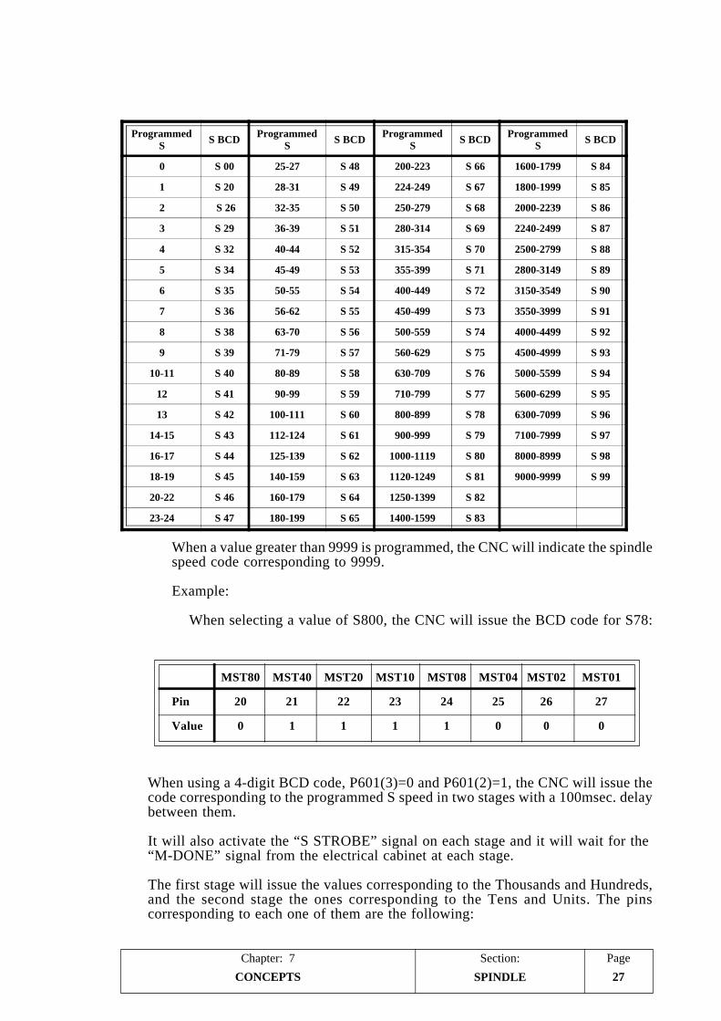
PageChapter: 7 Section:
CONCEPTS 27
ProgrammedS S BCD Programmed
S S BCD ProgrammedS S BCD Programmed
S S BCD
0 S 00 25-27 S 48 200-223 S 66 1600-1799 S 84
1 S 20 28-31 S 49 224-249 S 67 1800-1999 S 85
2 S 26 32-35 S 50 250-279 S 68 2000-2239 S 86
3 S 29 36-39 S 51 280-314 S 69 2240-2499 S 87
4 S 32 40-44 S 52 315-354 S 70 2500-2799 S 88
5 S 34 45-49 S 53 355-399 S 71 2800-3149 S 89
6 S 35 50-55 S 54 400-449 S 72 3150-3549 S 90
7 S 36 56-62 S 55 450-499 S 73 3550-3999 S 91
8 S 38 63-70 S 56 500-559 S 74 4000-4499 S 92
9 S 39 71-79 S 57 560-629 S 75 4500-4999 S 93
10-11 S 40 80-89 S 58 630-709 S 76 5000-5599 S 94
12 S 41 90-99 S 59 710-799 S 77 5600-6299 S 95
13 S 42 100-111 S 60 800-899 S 78 6300-7099 S 96
14-15 S 43 112-124 S 61 900-999 S 79 7100-7999 S 97
16-17 S 44 125-139 S 62 1000-1119 S 80 8000-8999 S 98
18-19 S 45 140-159 S 63 1120-1249 S 81 9000-9999 S 99
20-22 S 46 160-179 S 64 1250-1399 S 82
23-24 S 47 180-199 S 65 1400-1599 S 83
SPINDLE
When a value greater than 9999 is programmed, the CNC will indicate the spindlespeed code corresponding to 9999.
Example:
When selecting a value of S800, the CNC will issue the BCD code for S78:
MST80 MST40 MST20 MST10 MST08 MST04 MST02 MST01
Pin 20 21 22 23 24 25 26 27
Value 0 1 1 1 1 0 0 0
When using a 4-digit BCD code, P601(3)=0 and P601(2)=1, the CNC will issue thecode corresponding to the programmed S speed in two stages with a 100msec. delaybetween them.
It will also activate the “S STROBE” signal on each stage and it will wait for the“M-DONE” signal from the electrical cabinet at each stage.
The first stage will issue the values corresponding to the Thousands and Hundreds,and the second stage the ones corresponding to the Tens and Units. The pinscorresponding to each one of them are the following:

Section:Chapter: 7Page
CONCEPTS28 SPINDLE
Pin 1st stage 2nd stage
2021 Thousands Tens2223
2425 Hundreds Units2627
Example:
When selecting a value of S 1234, the CNC will show:
PIN 2 Digits 4 digits(value S81) 1st stage 2nd stage
20 (MST80) 1 0 021 (MST40) 0 0 022 (MST20) 0 0 123 (MST10) 0 1 1
24 (MST08) 0 0 025 (MST04) 0 0 126 (MST02) 0 1 027 (MST01) 1 0 0
PageChapter: 7 Section:
CONCEPTS 29SPINDLE RANGE CHANGE
7.6.1 SPINDLE SPEED RANGE CHANGE
With this CNC, the machine can have a gear box in order to adapt the speeds andtorques of the spindle motor to the various machining requirements.
Up to 4 spindle ranges may be set by means of machine parameters P7, P8, P9 andP10 specifying the maximum spindle rpm value for each one of them.
The value assigned to P7 must correspond to the lowest range (RANGE 1) and theone assigned to P10 to the highest range (RANGE 4).
When not using all 4 ranges, start the speed assignment from the lowest range upand set the unused ranges to the highest speed being used.
When the new spindle speed selected requires a range change, the CNC will executethe auxiliary M function corresponding to the new range.
The CNC uses the auxiliary functions: M41, M42, M43 and M44 to indicate to theelectrical cabinet which range must be selected: RANGE 1, RANGE 2, RANGE 3or RANGE 4).
Also, in order to facilitate the range change, the CNC offers the possibility to use aresidual analog output during a range change. Machine parameter for the spindle:P601(6).
The value of this residual analog voltage is defined by machine parameter P706 andthe oscillation period for this residual analog voltage is set by machine parameterP707.

Section:Chapter: 7Page
CONCEPTS30 SPINDLE RANGE CHANGE
The automatic range change is carried out as follows:
1.- Once the range change is detected, the CNC outputs the BCD value of thecorresponding M function: M41, M42, M43 or M44, via pins 20 thru 27 ofconnector I/O 1.
50 milliseconds later, it activates the “M Strobe” output to indicate to the electricalcabinet to execute the required M function. This signal is maintained active for100 milliseconds.
2.- When the electrical cabinet detects the “M Strobe” signal, must deactivate the“M-DONE” input of the CNC to “tell” it that the execution of the correspondingM function has begun.
3.- The electrical cabinet will execute the required M function using the BCD outputsof the CNC (pins 20 thru 27 of connector I/O 1).
4.- After keeping the BCD outputs active for 200 milliseconds, the CNC will outputthe residual analog output indicated by parameter P706 if so established byparameter P601(6).
The oscillation period for this residual analog voltage is determined by machineparameter P707.
5.- Once the range change is completed, the electrical cabinet must activate the M-DONE input of the CNC to “tell” it that the requested M function has beenexecuted.
Atention:
When the electrical cabinet has some device needing the BCD and “MStrobe” signals from the CNC active for a longer period of time, machineparameter P605(5) must be set “1” (the CNC waits for the down flank ofthe M-Done signal).

PageChapter: 7 Section:
CONCEPTS 31
7.7 FEED-HOLD, TRANSFER INHIBIT AND M-DONE SIGNALPROCESSING
The CNC has one single input (pin 15 of connector I/O 1) to process both signals.
This input must be normally high and these signals are processed as follows:
FEED HOLD
This signal may interrupt the execution of a block.
If while the axes are moving, this input is set low, the CNC maintains the spindlerotating and stops the axes by bringing their analog voltages to "0V" and keepingtheir enable signals on.
When this input is set back high, the CNC resumes the movement of the axes.
TRANSFER INHIBIT
If this signal is set low while executing a motion block, the CNC interrupts theexecution of the program once the current block is executed.
When this signal returns high, the CNC resumes the execution of the program.
M-DONE or CONFIRMATION FROM ELECTRICAL CABINET
This signal is used as confirmation from the electrical cabinet that the executionof the requested M, S or T function has been completed.
When the CNC sends to the electrical cabinet the BCD output signalscorresponding to the M, S or T function, the electrical cabinet must set this M-DONE input low.
The CNC will wait for the electrical cabinet to finish the execution of such functionand set this M-DONE input back high. This will "tell" the CNC that the executionof the corresponding auxiliary function has been completed.
"FEEDHOLD", "TRANSFERINHIBIT" AND "M DONE"

Section:Chapter: 7Page
CONCEPTS32
7.8 AUXILIARY FUNCTIONS M, S, T
M function
This CNC offers up to 100 M functions (M00 thru M99).
The CNC sends out to the electrical cabinet the number of the executed M functionvia pins 20 thru 27 of connector I/O1. Machine parameter P617(8) determineswhether this value is sent out in BCD or binary code.
Also, it must be borne in mind that the CNC has an internal "decoded M" table.The way to operate with this table is described later in this chapter.
Every time an M function of the decoded-M table is executed, the CNC updatesits corresponding outputs at connector I/O2.
Machine parameter P609(5) determines whether the CNC also outputs theircorresponding BCD or binary coded number via pins 20 thru 27 of connectorI/O1.
S function
Only to be used when the spindle speed output is in BCD (not analog). Machineparameter P601(3)=1.
Whenever a block containing a new spindle speed "S" is executed, the CNC willoutput the corresponding BCD code via pins 20 thru 27 of connector I/O 1.
T function
Whenever a block containing a new tool "T" is executed, the CNC will outputthe corresponding BCD code via pins 20 thru 27 of connector I/O 1.
This CNC also offers a tool table where the length and radius of each tool canbe defined. The CNC will take these dimensions into account when machiningwith tool compensation (G41, G42, G43).
The way to operate with this table is described in the chapter on "AuxiliaryFunctions" in this manual.
"M, S, T" FUNCTIONS

PageChapter: 7 Section:
CONCEPTS 33
7.8.1 DECODED M FUNCTION TABLE
To access this table, press the following keystroke sequence:
[AUX] (SPECIAL FUNCTIONS)[5] (AUXILIARY MODES)[1] (SPECIAL MODES)[0] [1] [0] [1] (Access code)[2] (AUXILIARY M FUNCTIONS)
The CNC shows the following information for each of the M functions set in this table:
M41 100100100100100 (outputs to be activated)00100100100100100 (outputs to be deactivated)
* The number of the M function already set. Mxx indicates that this position isfree and any other M function may be set.
* The first row has 15 characters. Each one corresponds to a decoded-M output ofconnector I/O2 and their value (0 or 1) indicates the following:
0 This M function must not activate its decoded output at connector I/O2.1 This M function must activate its decoded output at connector I/O2.
* The second row has 17 characters. The first 15 (from left to right) correspond tothe decoded-M output of I/O2 and their value (0 or 1) indicates the following:
0 This M function must not deactivate its decoded output at connector I/O2.1 This M function must deactivate its decoded output at connector I/O2.
Bit 16 determines whether the M function is executed at the beginning (if 0) orat the end of the block (if 1) where it is programmed. If this bit is set to "1" andthe programmed block contains a movement of axes, the M function will beexecuted once the axes have reached their target position.
Bit 17 determines the way the M function is transferred to the electrical cabinet.See the following section for its description.
For example: If the table corresponding to function M41 has been set as follows:
M41 100100100100100 (outputs to be activated)00100100100100100 (outputs to be deactivated)
The CNC will behave as follows whenever M41 is executed:
M01 M02 M03 M04 M05 M06 M07 M08 M09 M10 M11 M12 M13 M14 M15
Pin I/O2 3 4 5 6 7 8 9 10 11 12 13 25 24 23 22
at 24V x x x x x
at 0V x x x x x
Notmodified
x x x x x
"M, S, T" FUNCTIONS

Section:Chapter: 7Page
CONCEPTS34
7.8.2 M, S, T FUNCTION TRANSFER
Every time a block is executed, the CNC transfers to the electrical cabinet informationof the M, S, T functions activated in it.
First, the M function information is transferred, then, that of the S functions and,then, that of the T functions.
M function:
The CNC analyzes the M functions programmed in the block and, dependingon how they are defined, they will be output before or after moving the axes.
When sending more than one M function, the CNC will send them one by onestarting from the first one in the block and, once it has been sent out, it willoutput the next one and so forth.
When sending the auxiliary M functions to the electrical cabinet, the CNC usesthe BCD outputs (pins 20 thru 27 of connector I/O 1) and it activates the “MStrobe” output to “tell” the electrical cabinet to execute them.
Depending on how they are defined on the table, the CNC must wait or not forthe “M-DONE” signal to consider it executed.
If an M function which is not defined on the M function table is executed, theCNC will wait for the “M-DONE” signal before resuming the execution of theprogram.
S function transfer:
When a new spindle speed (S) is programmed, the CNC issues the correspondingBCD code (via pins 20 thru 27 of connector I/O 1) and it activates the “S Strobe”output to “tell” the electrical cabinet to execute it.
The CNC will wait for the “M-DONE” signal to consider it executed.
If the new selected “S” involves a range change, the CNC executes first the Mfunctions corresponding to the range change and then, it transfers the new selectedspindle speed.
T function transfer:
When selecting a new tool “T”, the CNC issues the corresponding BCD code(via pins 20 thru 27 of I/O 1) and it will activate the “T Strobe” to “tell” theelectrical cabinet to execute it.
The CNC will wait for the “M-DONE” signal to consider it executed.
"M, S, T" FUNCTIONS
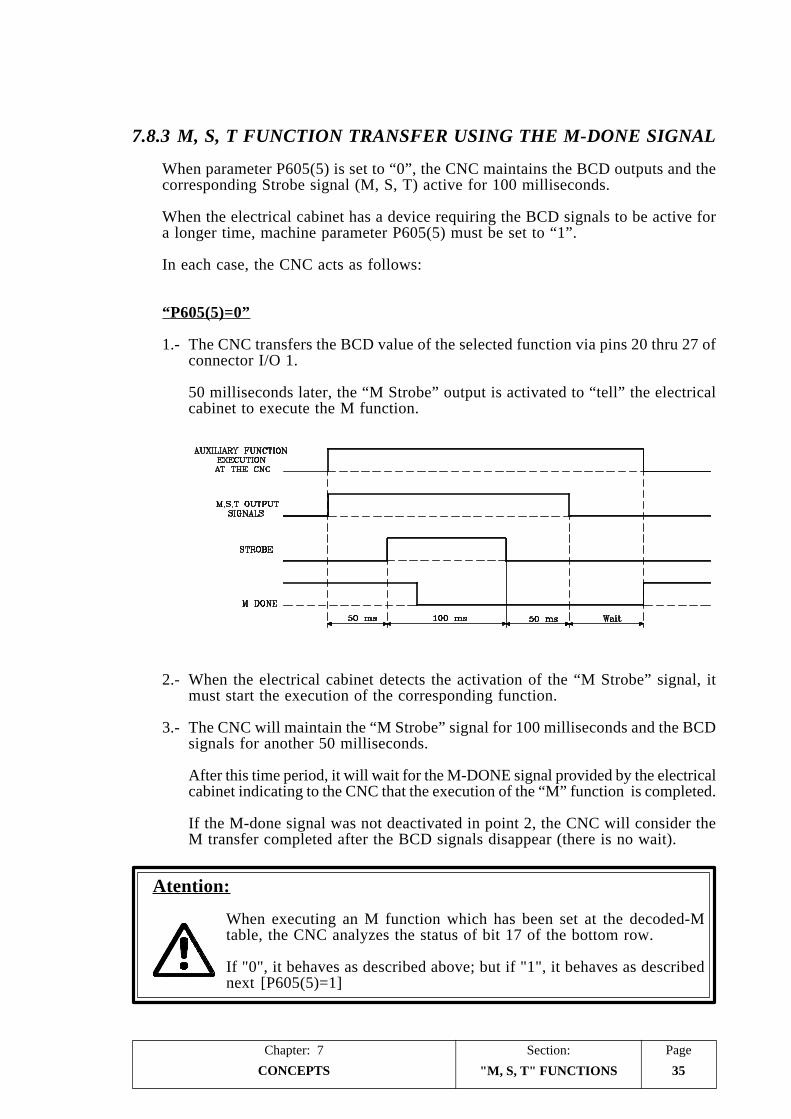
PageChapter: 7 Section:
CONCEPTS 35
7.8.3 M, S, T FUNCTION TRANSFER USING THE M-DONE SIGNAL
When parameter P605(5) is set to “0”, the CNC maintains the BCD outputs and thecorresponding Strobe signal (M, S, T) active for 100 milliseconds.
When the electrical cabinet has a device requiring the BCD signals to be active fora longer time, machine parameter P605(5) must be set to “1”.
In each case, the CNC acts as follows:
“P605(5)=0”
1.- The CNC transfers the BCD value of the selected function via pins 20 thru 27 ofconnector I/O 1.
50 milliseconds later, the “M Strobe” output is activated to “tell” the electricalcabinet to execute the M function.
2.- When the electrical cabinet detects the activation of the “M Strobe” signal, itmust start the execution of the corresponding function.
3.- The CNC will maintain the “M Strobe” signal for 100 milliseconds and the BCDsignals for another 50 milliseconds.
After this time period, it will wait for the M-DONE signal provided by the electricalcabinet indicating to the CNC that the execution of the “M” function is completed.
If the M-done signal was not deactivated in point 2, the CNC will consider theM transfer completed after the BCD signals disappear (there is no wait).
Atention:
When executing an M function which has been set at the decoded-Mtable, the CNC analyzes the status of bit 17 of the bottom row.
If "0", it behaves as described above; but if "1", it behaves as describednext [P605(5)=1]
"M, S, T" FUNCTIONS

Section:Chapter: 7Page
CONCEPTS36
“P605(5)=1”
This type of transfer is used when the electrical cabinet has a device which requiresthe BCD outputs from the CNC to be active for a longer period of time.
1.- The CNC sends the BCD value of the selected function via pins 20 thru 27of connector I/O 1.
50 milliseconds later, it activates the corresponding Strobe output to “tell”the electrical cabinet to execute the required auxiliary function.
2.-When the electrical cabinet detects the activation of one of the Strobe signals,it must begin the execution of the corresponding function deactivating theM-DONE signal to let the CNC know that this M function execution has begun.
3.-The CNC will maintain the Strobe signal for another 100 milliseconds andthe BCD outputs for another 150 milliseconds.
After this time period, it will wait for the electrical cabinet to reactivate theM-DONE input “telling” the CNC that the processing of the required functionhas concluded.
Atention:
When machine parameter P605(5) = 1 and an M function is executedwhich is set in the decoded-M table, the CNC ignores the status of bit 17of the bottom row.
"M, S, T" FUNCTIONS

APPENDIX A
CNC TECHNICAL CHARACTERISTICS
GENERAL CHARACTERISTICSThree 8-bit microprocessorsMemory capacity for up to 7 part-programs of 20 operations each.1 communication line: RS232C.6 feedback inputs up to 3 axes + 3 electronic handwheels.Resolution of 0.001 mm. or 0.0001 inches.Multiplying factor of up to x100 for sine-wave feedback signals.Feedrates from 0.001 mm/min up to 65535 mm/min (0.0001 through 2580 inches/min)Maximum axis travel ±8388.607 mm (330.2601 inches)11 optocoupled digital inputs.32 optocoupled digital outputs.4 analog outputs: ±10V (one per axis + spindle).Approximate weight: 12Kg.Maximum consumption in normal operation: 75W
PACKAGINGMeets the "EN 60068-2-32" standard.
POWER SUPPLYHigh performance Switching power supply.Universal power supply with any input between 100 V AC and 240 V AC (±10% and -15%).AC frequency: 50 - 60 Hz ±1% and ±2% during very short periods.Power outages. Meets the EN 61000-4-11 standard. It is capable of withstanding micro outages of up to 10milliseconds.Harmonic distortion: Less than 10% of the rms voltage between low voltage conductors (sum of the 2nd
through the 5th harmonic)
ELECTRICAL CHARACTERISTICS OF FEEDBACK INPUTS+5V power consumption: 750 mA (250 mA per axis).-5V power consumption: 0.3A (100 mA per axis).Operating levels for square-wave signals:
Maximum frequency: 200KHz.Maximum separation between flanks: 950 nsec.Phase shift: 90° ±20°High threshold (logic state "1"): 2.4V. < V
IH < 5V.
Low threshold (logic state "0"): -5V. < VIL
< 0.8V.Vmax.: ±7 V.Hystheresis: 0.25 V.Maximum input current: 3mA.
Operating levels for sine-wave signals:Maximum frequency: 25KHz.Peak to peak voltage: 2V. < Vpp < 6V.Input current I
I 1mA.
ELECTRICAL CHARACTERISTICS OF DIGITAL INPUTSNominal voltage: +24 V DC. (Maximum: +30Vdc; Minimum: +18Vdc)High threshold (logic state "1"): V
IH >+18 V DC.
Low threshold (logic state "0"): VIL
< +5 V DC. or not connected.Typical consumption per input: 5 mA. (Maximum: 7 mA)Protection by means of galvanic isolation by opto-couplers.Protection against reversed connection up to -30 V DC.

ELECTRICAL CHARACTERISTICS OF DIGITAL OUTPUTSNominal voltage: +24 V DC. (Maximum: +30Vdc; Minimum: +18Vdc)Output voltage Vout = Power Supply voltage - 2 V DC.Maximum output current: 100 mA.Protection by means of galvanic isolation by opto-couplers.Protection by means of external 3Amp fuse against reversed connection up to -30 V DC andovervoltage of the external power supply greater than 33V DC.
CRTMonitor 8" monochrome Deflection: 90 degreesScreen: Anti-glare Phosphor: PLA (amber)Resolution: 600 lines Display surface: 146 x 119 mm.
SWEEP FREQUENCYVertical synchronism: 50-60 Hz positive Horizontal synchronism: 19.2 KHz positive
AMBIENT CONDITIONSRelative humidity: 30-95% non condensingOperating temperature: 5ºC - 40ºC (41º F - 104ºF) with an average lower than 35ºC (95º F)Storage temperature : between 25º C (77ºF and 70º C (158º F).Maximum operating altitude : Meets the “IEC 1131-2” standard.
VIBRATIONUnder working conditions: 10-50 Hz. amplitude 0.2 mm.Under transport conditions: 10-50 Hz. amplitude 1 mm, 50-300 Hz. and acceleration of 5g.Free fall of packaged equipment: 1 m.
ELECTROMAGNETIC COMPATIBILITYSee Declaration of Conformity in the introduction of this manual.
SAFETYSee Declaration of Conformity in the introduction of this manual
DEGREE OF PROTECTIONCentral Unit : IP 54Accessible parts inside the enclosure: IP 1X
The machine manufacturer must comply with the “EN 60204-1 (IEC-204-1)”, standardregarding protection against electrical shock due to I/O contact failures with external powersupply when not hooking up this connector before turning the power supply on.Access to the inside of the unit is absolutely forbidden to non authorized personnel.

BATTERY3.5V lithium battery.Estimated life: 10 yearsAs from error indication (low battery), the information contained in memory will be kept for a maxi-mum of 10 days with the CNC off. It must be replaced.Caution, due to risk of explosion or combustion:
Do not attempt to recharge the battery.Do not expose it to temperatures over 100 °C (232°F).Do not short-circuit its leads.
Atention:
To avoid excessive heating of internal circuits, the several ventilation slits must notbe obstructed. It is also necessary to install a ventilation system which extracts hot airfrom the enclosure or desk supporting the CNC.

APPENDIX B
ENCLOSURES
The minimum distance between the sides of the CNC and its enclosure in order to meet the required ambientconditions must be the following:
When using a fan to better ventilate the enclosure, a DC FAN must be used since an AC fan may generateelectromagnetic interference resulting in distorted images being displayed by the CRT.
The CNC must be secured as shown below (dimensions in mm):

APPENDIX C
CNC INPUTS AND OUTPUTS
INPUTS
Pin Connector Function
10 I/O 1 X axis Home switch11 I/O 1 Y axis Home switch12 I/O 1 Z axis Home switch14 I/O 1 Emergency stop.15 I/O 1 /Feed hold - /Transfer inhibit - /M-done16 I/O 1 /Stop17 I/O 1 Start - rapid jog18 I/O 1 Conditional input (block skip)19 I/O 1 DRO mode
OUTPUTS
Pin Connector Function
2 I/O 1 T Strobe3 I/O 1 S Strobe4 I/O 1 M Strobe5 I/O 1 Emergency6 I/O 1 Threading on7 I/O 1 Z axis enable8 I/O 1 Y axis enable9 I/O 1 X axis enable
20 I/O 1 MST8021 I/O 1 MST4022 I/O 1 MST2023 I/O 1 MST1024 I/O 1 MST0825 I/O 1 MST0426 I/O 1 MST0227 I/O 1 MST01
30, 31 I/O 1 X axis analog output32, 33 I/O 1 Y axis analog output34, 35 I/O 1 Z axis analog output36, 37 I/O 1 Spindle analog output
3 I/O 2 Decoded M01 output. Coolant4 I/O 2 Decoded M02 output5 I/O 2 Decoded M03 output6 I/O 2 Decoded M04 output7 I/O 2 Decoded M05 output8 I/O 2 Decoded M06 output9 I/O 2 Decoded M07 output
10 I/O 2 Decoded M08 output11 I/O 2 Decoded M09 output12 I/O 2 Decoded M10 output13 I/O 2 Decoded M11 output21 I/O 2 "Jog mode selected" output22 I/O 2 Decoded M15 output23 I/O 2 Decoded M14 output - Reset24 I/O 2 Decoded M13 output - Cycle on - Automatic - G0025 I/O 2 Decoded M12 output - Vertical axis movement

APPENDIX D
2-DIGIT BCD CODED "S" OUTPUT CONVERSION TABLE
ProgrammedS S BCD Programmed
S S BCD ProgrammedS S BCD Programmed
S S BCD
0 S 00 25-27 S 48 200-223 S 66 1600-1799 S 84
1 S 20 28-31 S 49 224-249 S 67 1800-1999 S 85
2 S 26 32-35 S 50 250-279 S 68 2000-2239 S 86
3 S 29 36-39 S 51 280-314 S 69 2240-2499 S 87
4 S 32 40-44 S 52 315-354 S 70 2500-2799 S 88
5 S 34 45-49 S 53 355-399 S 71 2800-3149 S 89
6 S 35 50-55 S 54 400-449 S 72 3150-3549 S 90
7 S 36 56-62 S 55 450-499 S 73 3550-3999 S 91
8 S 38 63-70 S 56 500-559 S 74 4000-4499 S 92
9 S 39 71-79 S 57 560-629 S 75 4500-4999 S 93
10-11 S 40 80-89 S 58 630-709 S 76 5000-5599 S 94
12 S 41 90-99 S 59 710-799 S 77 5600-6299 S 95
13 S 42 100-111 S 60 800-899 S 78 6300-7099 S 96
14-15 S 43 112-124 S 61 900-999 S 79 7100-7999 S 97
16-17 S 44 125-139 S 62 1000-1119 S 80 8000-8999 S 98
18-19 S 45 140-159 S 63 1120-1249 S 81 9000-9999 S 99
20-22 S 46 160-179 S 64 1250-1399 S 82
23-24 S 47 180-199 S 65 1400-1599 S 83

APPENDIX E
MACHINE PARAMETER SUMMARY CHART
GENERAL MACHINE PARAMETERS
P5 Mains frequency (50/60)P99 Language (0=Spanish, 1=German, 2=English, 3=French, 4=Italian)P13 Measuring units: mm (0), inches (1)P6 Theoretical (1) or Real (0) displayP617(5), P605(6), P617(4) X, Y, Z as DRO axis (0=No, 1=Yes)P618(6), P618(5), P618(4) X, Y, Z axis display (1=No, 0=Yes)P701 Number of tools (0..98)P626(1) The CNC displays the tool base (1) or tool tip (0) positionP743 Subroutine to be executed before the T functionP745 Subroutine to be executed after the "T" function.P628(1) Display of the following error (0=No, 1=Yes)P628(6) O1 may be turned on/off only when spindle is off (0=No, 1=Yes)
I/O RELATED MACHINE PARAMETERS
P605(8) Normal status of Emergency output (pin 5 of I/O1). (0=0V, 1=24V)P605(5) The CNC waits for trailing edge of "M-done" input (0=No, 1=Yes)P609(7) Pin 17 of I/O 1 as "Rapid jog" (0=No, 1=Yes)P609(3) Pin 23 of I/O 2 as "RESET" (0=No, 1=Yes)P611(1) Pin 24 of I/O 2 as "Program block in execution" (0=No, 1=Yes)P611(6) Pin 24 of I/O 2 as "P99996 in execution" (0=No, 1=Yes)P613(4) Pin 24 of I/O 2 as "Rapid traverse" (0=No, 1=Yes)P613(2) Pin 25 of I/O 2 as "Vertical move" output (0=No, 1=Yes)P617(8) M function output in BCD (0) or Binary (1)P609(5) M functions set on the "M" table are output in BCD (0) or binary (1)P602(8,7,6,5), P603(1) Feedback alarm cancellation connect.: A1, A2, A3, A4, A5. (0=No,1=Yes)
HANDWHEEL MACHINE PARAMETERS
P612(1), P626(8), P627(8) Electronic handwheel associated with X, Y, Z (0=No, 1=Yes)P613(1) Electronic handwheel model FAGOR 100P (0=No, 1=Yes)P612(2), P626(2), P627(2) Counting direction of the electronic handwheel for X, Y, ZP612(3), P626(3), P627(3) Feedback units of electronic handwheels X,Y,Z (0=mm, 1=inch)P612(4,5), P626(4,5), P627(4,5) Counting resolution of the electronic handwheel for X, Y, ZP612(6), P626(6), P627(6) Multiplying factor for handwheel signals X,Y,Z (0=x4, 1=x2)P628(5) Handwheels only operate at handwheel positions of FOS (1=No, 0=Yes)P628(8) The machine uses mechanical handwheels (0=No, 1=Yes)P815 Delay before opening the closed loop. (1=10ms)
MACHINE PARAMETERS RELATED TO OPERATING MODE
P609(8) Axis orientation in graphic representation (0=Mill, 1=Boring mill)P605(4) Axis orientation in XZ planeP628(7) Z interpolation (1=No, 0=Yes)P618(1) CYCLE START key inhibit (0=No, 1=Yes)P606(3) M30 executed when switching to Jog mode (0=No, 1=Yes)P12 Continuous (0) or pulsating (1) axis jogP609(6) Maximum incremental Jog (0=10mm or 1 inch, 1=1mm or 0.1 inch)P606(2) Maximum Feedrate Override Switch value applied by the CNC (0=120%, 1=100%)P4 Feedrate Override Switch active in G00 (0=No, 1=Yes)P613(5) G05 or G07 on CNC power-up (0=G07, 1=G05)P715 Dwell between G07 blocks (square corner) (1=10ms)P611(5) Feedrate units in G94 (0=1mm/min or 0.1 inch/min, 1=0.1mm/min or 0.01 inch/min)P610(1) Feed-Hold in G47 (0=No, 1=Yes)P628(4) The "rapid jog" key applies a feedrate override range over 100% (0=No, 1=Yes)
MACHINE PARAMETERS RELATED WITH RS232C SERIAL LINE
P0 Communications speed (baudrate) (110, 150, 300, 600, 1200, 2400, 4800, 9600)P1 Number of data bits per character (7/8)P2 Parity (0= No, 1= Odd, 2= Even)P3 Stop bits (1/2)P607(3) DNC (0=No, 1=Yes)P607(4) Communications settings. FAGOR cassette (0) or FAGOR Floppy Disk Unit (1)P607(5) DNC protocol active on power-up (0=No, 1=Yes)P607(6) The CNC aborts DNC communications (program debugging) (1=No, 0=Yes)P607(7) Status report by interruption (0=No, 1=Yes)
Section 4.3
Section 4.3.4
Section 4.3.1
Section 4.3.2
Section 4.3.3

MACHINE PARAMETERS FOR THE AXES
P100, P200, P300 Sign of the analog output for X, Y, ZP101, P201, P301 Counting direction for X, Y, ZP102, P202, P302 Jogging direction for X, Y, Z
MACHINE PARAMETERS FOR AXIS RESOLUTION
P103, P203, P303 Counting resolution for X, Y, ZP622(1), P622(2), P622(3) Resolution units for X, Y, Z sine-wave feedbackP604(4), P604(3), P604(2) Feedback units for X, Y, Z (0=mm, 1=inch)P106, P206, P306 Feedback signal type for X, Y, Z (0=Squarewave, 1=Sinewave)P604(8), P604(7), P604(6) Multiplying factor for X, Y, Z feedback signals (0=x4, 1=x2)P603(8), P603(7), P603(6) Binary encoder for X, Y, Z (0=No, 1=Yes)P610(8), P610(7), P610(6) Equivalence of the binary encoder for X, Y, Z
MACHINE PARAMETERS FOR ANALOG OUTPUTS
P117, P217, P317 Minimum analog output for X, Y, Z (1=2.5mV)P104, P204, P304 Dwell between Enable and Analog output for X, Y, Z (0=No, 1=Yes)P118, P218, P318 In-position zone (dead-band) for X, Y, Z (0..255 microns)P105, P205, P305 Continuous control of X, Y, Z (0=No, 1=Yes)
MACHINE PARAMETERS FOR AXIS TRAVEL LIMITS
P107, P207, P307 Positive travel limit for X, Y, ZP108, P208, P308 Negative travel limit for X, Y, Z
FEEDRATE RELATED MACHINE PARAMETERS
P110, P210, P310 Maximum programmable feedrate X, Y, ZP111, P211, P311 G00 feedrate for X, Y, ZP729 Maximum feedrate for circular interpolationsP708 Feedrate/Override when analog output reaches 10V.P714 Error if actual feedrate not within 50% to 200% of programmed valueP615(6) Programmed feedrate in mm/min (0) or inches/minute (1)
MACHINE PARAMETERS FOR AXIS CONTROL
P114, P214, P314 Proportional gain K1 for X, Y, ZP115, P215, P315 Gain break point for X, Y, ZP116, P216, P316 Proportional gain K2 for X, Y, ZP611(8) In G00 and F00, proportional gain K2 from 256 microns on (0=No, 1=Yes)P726 Recovery of programmed position on "non-continuously" controlled axes
HOME SEARCH RELATED MACHINE PARAMETERS
P119, P219, P319 Home coordinates for X, Y, ZP623(8), P623(7), P623(6) Home search direction for X, Y, Z (0=Positive, 1=Negative)P600(8), P600(7), P600(6) Home pulse (marker) type for X, Y, Z (1=Positive, 0=Negative)P602(4), P602(3), P602(2) Home switch for X, Y, Z (1=No, 0=Yes)P112, P212, P312 1st homing feedrate for X, Y, ZP810, P811, P812 2nd homing feedrate for X, Y, ZP611(2) Mandatory home search on power-up (0=No, 1=Yes)P804 Jogging feedrate prior to mandatory home searchP606(4) Home search function generates an M30 (0=No, 1=Yes)
ACCELERATION/DECELERATION RELATED MACHINE PARAMETERS
P721, P722, P723 Apply ACC/DEC onto X, Y, Z (1=20ms)P613(7) Linear ACC/DEC on all linear interpolation (G01) (0=No, 1=Yes)P620(2) Linear ACC/DEC in G05 (round corner) (1=No, 0=Yes)P624(8) Bell-shaped ACC/DEC (0=No, 1=Yes)P744 Bell-shaped ACC/DEC ramp duration (1=10ms)P732, P733, P734 FEED-FORWARD gain for X, Y, Z
Section 5.
Section 5.1
Section 5.2
Section 5.3
Section 5.4
Section 5.5
Section 5.6
Section 5.7

LEADSCREW RELATED MACHINE PARAMETERS
P109, P209, P309 Leadscrew backlash compensation for X, Y, Z (0..255 microns)P624(1), P624(2), P624(3) Sign of leadscrew backlash compensation X, Y, Z (0=Pos., 1=Neg.)P113, P213, P313 Additional analog pulse for X, Y, Z (1=2.5mV)P606(8), P606(7), P606(6) Leadscrew error compensation for X, Y, Z (0=No, 1=Yes)
SPECIAL MACHINE PARAMETERS
P609(1) Machine with travels over 8 meters (0=No, 1=Yes)P617(6) Resolution of 0.0001 millimeters (0.00001 inches). (0=No, 1=Yes)P908, P909 Collision zone for Y and Z
SPINDLE MACHINE PARAMETERS
MACHINE PARAMETERS FOR SPINDLE RANGE CHANGE
P7, P8, P9, P10 Maximum speed for ranges 1, 2, 3 and 4 (0..9999 rpm)P601(6) Residual analog voltage "S" for range change (0=No, 1=Yes)P706 Value of the residual analog voltage (1=2.5mV)P707 Oscillation period during range change
MACHINE PARAMETERS FOR ANALOG SPINDLE SPEED OUTPUT
P601(4) Sign of the analog spindle speed output "S"P610(4) Unipolar (1) or bipolar (0) analog spindle speed output "S"P609(4) All spindle speed changes generate an "S Strobe" signal (0=No, 1=Yes)
MACHINE PARAMETERS FOR BCD-CODED SPINDLE SPEED OUTPUT
P601(3) 2-digit BCD coded output (0=No, 1=Yes)P601(2) 4-digit BCD coded output (0=No, 1=Yes)
Section 5.8
Section 5.9
Section 6.1
Section 6.2
Section 6.3

APPENDIX F
SEQUENTIAL MACHINE PARAMETER LIST
P0 Communications baudrate (110, 150, 300, 600, 2400, 4800, 9600) .................. Section 4.3.4P1 Communications data bits (7/8) ............................................................................. Section 4.3.4P2 Parity (0=No, 1=Odd, 2=Even) ................................................................................ Section 4.3.4P3 Stop bits (1/2) ........................................................................................................... Section 4.3.4P4 Feedrate Override active in G00 (0=No, 1=Yes) ................................................... Section 4.3.3P5 Mains (AC) frequency (50/60) ................................................................................ Section 4.3P6 Theoretical (1) or real (0) display .......................................................................... Section 4.3P7 Maximum spindle speed for RANGE 1 (0..9999 rpm) ......................................... Section 6.1P8 Maximum spindle speed for RANGE 2 (0..9999 rpm) ......................................... Section 6.1P9 Maximum spindle speed for RANGE 3 (0..9999 rpm) ......................................... Section 6.1P10 Maximum spindle speed for RANGE 4 (0..9999 rpm) ......................................... Section 6.1P11 Not being used at this time "= 0"P12 Continuous (0) or pulsating (1) axis JOG .............................................................. Section 4.3.3P13 Measuring units. (0= mm, 1= inches) ..................................................................... Section 4.3P99 Language (0=Spanish, 1= German, 2=English, 3=French, 4=Italian) .................. Section 4.3
P100 Sign of the X axis analog output ........................................................................... Section 5.P101 Counting direction of the X axis ........................................................................... Section 5.P102 X axis jogging direction ......................................................................................... Section 5.P103 X axis feedback (counting) resolution ................................................................... Section 5.1P104 Dwell between Enable and analog output for the X axis (0=No, 1=Yes) ........... Section 5.2P105 Continuous control of the X axis (0=No, 1=Yes) ................................................. Section 5.2P106 Type of feedback signal for the X axis (0=Squarewave, 1=Sinewave) ............... Section 5.1P107 X axis positive travel limit ..................................................................................... Section 5.3P108 X axis negative travel limit .................................................................................... Section 5.3P109 X axis leadscrew backlash (0..255 microns) .......................................................... Section 5.8P110 X axis maximum programmable feedrate ............................................................... Section 5.4P111 X axis G00 feedrate ................................................................................................. Section 5.4P112 1st home searching feedrate for the X axis ........................................................... Section 5.6P113 Additional analog pulse for the X axis (1=2.5mV) ............................................... Section 5.8P114 Proportional gain K1 for the X axis ....................................................................... Section 5.5P115 Gain break point for the X axis .............................................................................. Section 5.5P116 Proportional gain K2 for the X axis ....................................................................... Section 5.5P117 Minimum X axis analog (1=2.5mV) ....................................................................... Section 5.2P118 In-position zone (dead band) for the X axis (0..255 microns) ............................. Section 5.2P119 X axis home coordinate ........................................................................................... Section 5.6
P200 Sign of the Y axis analog output ........................................................................... Section 5.P201 Counting direction of the Y axis ........................................................................... Section 5.P202 Y axis jogging direction ......................................................................................... Section 5.P203 Y axis feedback (counting) resolution ................................................................... Section 5.1P204 Dwell between Enable and analog output for the Y axis (0=No, 1=Yes) ........... Section 5.2P205 Continuous control of the Y axis (0=No, 1=Yes) ................................................. Section 5.2P206 Type of feedback signal for the Y axis (0=Squarewave, 1=Sinewave) ............... Section 5.1P207 Y axis positive travel limit ..................................................................................... Section 5.3P208 Y axis negative travel limit .................................................................................... Section 5.3P209 Y axis leadscrew backlash (0..255 microns) .......................................................... Section 5.8P210 Y axis maximum programmable feedrate ............................................................... Section 5.4P211 Y axis G00 feedrate ................................................................................................. Section 5.4P212 1st home searching feedrate for the Y axis ........................................................... Section 5.6P213 Additional analog pulse for the Y axis (1=2.5mV) ............................................... Section 5.8P214 Proportional gain K1 for the Y axis ....................................................................... Section 5.5P215 Gain break point for the Y axis .............................................................................. Section 5.5P216 Proportional gain K2 for the Y axis ....................................................................... Section 5.5P217 Minimum Y axis analog (1=2.5mV) ....................................................................... Section 5.2P218 In-position zone (dead band) for the Y axis (0..255 microns) ............................. Section 5.2P219 Y axis home coordinate ........................................................................................... Section 5.6
P300 Sign of the Z axis analog output ........................................................................... Section 5.P301 Counting direction of the Z axis ............................................................................ Section 5.P302 Z axis jogging direction .......................................................................................... Section 5.P303 Z axis feedback (counting) resolution ................................................................... Section 5.1P304 Dwell between Enable and analog output for the Z axis (0=No, 1=Yes) ........... Section 5.2P305 Continuous control of the Z axis (0=No, 1=Yes) .................................................. Section 5.2P306 Type of feedback signal for the Z axis (0=Squarewave, 1=Sinewave) ................ Section 5.1P307 Z axis positive travel limit ...................................................................................... Section 5.3P308 Z axis negative travel limit ..................................................................................... Section 5.3P309 Z axis leadscrew backlash (0..255 microns) .......................................................... Section 5.8

P310 Z axis maximum programmable feedrate ............................................................... Section 5.4P311 Z axis G00 feedrate .................................................................................................. Section 5.4P312 1st home searching feedrate for the Z axis ............................................................ Section 5.6P313 Additional analog pulse for the Z axis (1=2.5mV) ............................................... Section 5.8P314 Proportional gain K1 for the Z axis ....................................................................... Section 5.5P315 Gain break point for the Z axis .............................................................................. Section 5.5P316 Proportional gain K2 for the Z axis ....................................................................... Section 5.5P317 Minimum Z axis analog (1=2.5mV) ....................................................................... Section 5.2P318 In-position zone (dead band) for the Z axis (0..255 microns) ............................. Section 5.2P319 Z axis home coordinate ........................................................................................... Section 5.6
P400 thru P519 Not being used at this time "=0"
P600(8) Type of X axis marker pulse (home) (0=Negative, 1=Positive) ........................... Section 5.6(7) Type of Y axis marker pulse (home) (0=Negative, 1=Positive) ........................... Section 5.6(6) Type of Z axis marker pulse (home) (0=Negative, 1=Positive) ........................... Section 5.6(5) Not being used at this time "=0"(4) Not being used at this time "=0"(3) Not being used at this time "=0"(2) Not being used at this time "=0"(1) Not being used at this time "=0"
P601(8) Not being used at this time "=0"(7) Not being used at this time "=0"(6) Residual analog S output during range change (0=No, 1=Yes) .......................... Section 6.1(5) Not being used at this time "=0"(4) Sign of the spindle analog output .......................................................................... Section 6.2(3) S output in 2-digit BCD code (0=No, 1=Yes) ....................................................... Section 6.3(2) S output in 2-digit BCD code (0=No, 1=Yes) ....................................................... Section 6.3(1) Not being used at this time "=0"
P602(8) Cancellation of A1 feedback alarm (0=No, 1=Yes) .............................................. Section 4.3.1(7) Cancellation of A2 feedback alarm (0=No, 1=Yes) .............................................. Section 4.3.1(6) Cancellation of A3 feedback alarm (0=No, 1=Yes) .............................................. Section 4.3.1(5) Cancellation of A4 feedback alarm (0=No, 1=Yes) .............................................. Section 4.3.1(4) X axis home switch (1=No, 0=Yes) ........................................................................ Section 5.6(3) Y axis home switch (1=No, 0=Yes) ........................................................................ Section 5.6(2) Z axis home switch (1=No, 0=Yes) ........................................................................ Section 5.6(1) Not being used at this time "=0"
P603(8) X axis with binary encoder (0=No, 1=Yes) ............................................................ Section 5.1(7) Y axis with binary encoder (0=No, 1=Yes) ............................................................ Section 5.1(6) Z axis with binary encoder (0=No, 1=Yes) ............................................................ Section 5.1(5) Not being used at this time "=0"(4) Not being used at this time "=0"(3) Not being used at this time "=0"(2) Not being used at this time "=0"(1) Cancellation of A5 feedback alarm (0=No, 1=Yes) .............................................. Section 4.3.1
P604(8) X axis feedback signal multiplying factor (0=x4, 1=x2) ..................................... Section 5.1(7) Y axis feedback signal multiplying factor (0=x4, 1=x2) ..................................... Section 5.1(6) Z axis feedback signal multiplying factor (0=x4, 1=x2) ..................................... Section 5.1(5) Not being used at this time "=0"(4) X axis feedback units (0=mm, 1=inch) .................................................................. Section 5.1(3) Y axis feedback units (0=mm, 1=inch) .................................................................. Section 5.1(2) Z axis feedback units (0=mm, 1=inch) ................................................................... Section 5.1(1) Not being used at this time "=0"
P605(8) Normal status of Emergency output at pin 5 of I/O1. (0=5V, 1=24V) ................ Section 4.3.1(7) Not being used at this time "=0"(6) Y axis as DRO axis (0=No, 1=Yes) ........................................................................ Section 4.3(5) CNC waits for trailing edge at "M-done" input (0=No, 1=Yes) ........................... Section 4.3.1(4) Axis orientation on the XZ plane .......................................................................... Section 4.3.3(3) Not being used at this time "=0"(2) Not being used at this time "=0"(1) Not being used at this time "=0"

P606(8) X axis leadscrew error compensation (0=No, 1=Yes) ............................................ Section 5.8(7) Y axis leadscrew error compensation (0=No, 1=Yes) ............................................ Section 5.8(6) Z axis leadscrew error compensation (0=No, 1=Yes) ............................................ Section 5.8(5) Not being used at this time "=0"(4) Home search function generates an M30 (0=No, 1=Yes) ..................................... Section 5.6(3) M30 executed when switching to JOG mode (0=No, 1=Yes) .............................. Section 4.3.3(2) Maximum Feedrate override value applied by CNC (0=120%, 1=100%) .......... Section 4.3.3(1) Not being used at this time "=0"
P607(8) Not being used at this time "=0"(7) Status report by interruption (0=No, 1=Yes) ......................................................... Section 4.3.4(6) CNC aborts DNC communications (program debugging) (1=No, 0=Yes) .......... Section 4.3.4(5) DNC protocol active on power-up (0=No, 1=Yes) ................................................ Section 4.3.4(4) Communications setting. FAGOR cassette (0) FAGOR Floppy Disk Unit (1) ... Section 4.3.4(3) DNC (0=No, 1=Yes) ................................................................................................. Section 4.3.4(2) Not being used at this time "=0"(1) Not being used at this time "=0"
P608 Not being used at this time "=0"
P609(8) Axis orientation for graphic display (0=Mill, 1=Boring Mill) ............................ Section 4.3.3(7) Pin 17 of connector I/O 1 as "rapid jog" (0=No, 1=Yes) ...................................... Section 4.3.1(6) Maximum incremental JOG move (0=10mm or 1", 1=1mm or 0.1") ................... Section 4.3.3(5) M functions set at M table are output in BCD or binary (1=No, 0=Yes) ........... Section 4.3.1(4) All spindle speed changes generate an S strobe output (0=No, 1=Yes) ............. Section 6.2(3) Pin 23 of connector I/O 2 as "RESET" (0=No, 1=Yes) ......................................... Section 4.3.1(2) Not being used at this time "=0"(1) Machine with axis travel over 8 meters (0=No, 1=Yes) ....................................... Section 5.9
P610(8) X axis binary encoder equivalence ........................................................................ Section 5.1(7) Y axis binary encoder equivalence ........................................................................ Section 5.1(6) Z axis binary encoder equivalence ........................................................................ Section 5.1(5) Not being used at this time "=0"(4) S analog output: unipolar (1) or bipolar (0) .......................................................... Section 6.2(3) Not being used at this time "=0"(2) Not being used at this time "=0"(1) Feed-Hold in G47 (0=No, 1=Yes) ........................................................................... Section 4.3.3
P611(8) In G00 and F00 proportional gain break-point at 256 µm (0=No, 1=Yes) ......... Section 5.5(7) Not being used at this time "=0"(6) Pin 24 of I/O 2 as "P99996 in execution" output (0=No, 1=Yes) ....................... Section 4.3.1(5) Feedrate units in G94 (0=1mm/min or 0.1"/min, 1=0.1mm/min or 0.01/min") .. Section 4.3.3(4) Not being used at this time "=0"(3) Not being used at this time "=0"(2) Home search required after power-up (0=No, 1=Yes) ........................................... Section 5.6(1) Pin 24 of I/O 2 as "Program block in execution" output (0=No, 1=Yes) ........... Section 4.3.1
P612(8) Not being used at this time "=0"(7) Not being used at this time "=0"(6) Multplying factor for X axis electronic handwheel signals (0=x4, 1=x2) .......... Section 4.3.2(5) Feedback (counting) resolution of the X axis electronic handwheel .................. Section 4.3.2(4) Feedback (counting) resolution of the X axis electronic handwheel .................. Section 4.3.2(3) Feedback units of the X axis electronic handwheel (0=mm, 1=inch) ................. Section 4.3.2(2) Counting direction of the X axis electronic handwheel ...................................... Section 4.3.2(1) There is an electronic handwheel associated with the X axis (0=No, 1=Yes) .... Section 4.3.2
P613(8)(7) Acc/dec in all linear interpolations (0=No, 1=Yes) .............................................. Section 5.7(6) Not being used at this time "=0"(5) G05 or G07 active on power-up (0=G07, 1=G05) ................................................. Section 4.3.3(4) Pin 24 of connector I/O 2 as "rapid traverse" output (0=No, 1=Yes) .................. Section 4.3.1(3) Not being used at this time "=0"(2) Pin 25 of connector I/O 2 as "vertical move" output ........................................... Section 4.3.1(1) Electronic handwheel model: FAGOR 100P (0=No, 1=Yes) ................................ Section 4.3.2
P614 Not being used at this time "=0"
P615(8,7) Not being used at this time "=0"(6) Feedrate in 0.1inch/min (0) or inches/min. (1) .......................................... Section 5.4(5,4,3,2,1) Not being used at this time "=0"
P616 Not being used at this time "=0"

P617(8) M function output in BCD (0) or Binary (1) ............................................. Section 4.3.1(7) Not being used at this time "=0"(6) 0.0001 millimeters (0.00001 inch) resolution (0=No, 1=Yes) .................. Section 5.9(5) X as DRO axis (0=No, 1=Yes) ..................................................................... Section 4.3(4) Z as DRO axis (0=No, 1=Yes) ...................................................................... Section 4.3(3,2,1) Not being used at this time "=0"
P618(8) Not being used at this time "=0"(7) Not being used at this time "=0"(6) X axis display (1=No, 0=Yes) ...................................................................... Section 4.3(5) Y axis display (1=No, 0=Yes) ...................................................................... Section 4.3(4) Z axis display (1=No, 0=Yes) ...................................................................... Section 4.3(3) Not being used at this time "=0"(2) Not being used at this time "=0"(1) CYCLE START key inhibited (0=No, 1=Yes) ........................................... Section 4.3.3
P619 Not being used at this time "=0"
P620(8,7,6,5,4,3) Not being used at this time "=0"(2) Acc/dec. in G05 (round corner) (1=No, 0=Yes) .......................................... Section 5.7(1) PLCI marks M1801..M1899 to send messages to CNC (0=No, 1=Yes) ... PLCI manual
P621(8,7,6,5,4,3,2) Not being used at this time "=0"(1) The CNC has a PLCI (0=No, 1=Yes) .......................................................... PLCI manual
P622(8,7,6,5,4) Not being used at this time "=0"(3) Z axis sine-wave feedback resolution ......................................................... Section 5.1(2) Y axis sine-wave feedback resolution ......................................................... Section 5.1(1) X axis sine-wave feedback resolution ......................................................... Section 5.1
P623(8) X axis home searching direction (0=Positive, 1=Negative) ...................... Section 5.6(7) Y axis home searching direction (0=Positive, 1=Negative) ...................... Section 5.6(6) Z axis home searching direction (0=Positive, 1=Negative) ...................... Section 5.6(5,4,3,2,1) Not being used at this time "=0"
P624(8) Bell shaped acc/dec. (0=No, 1=Yes) ........................................................... Section 5.7(7) Not being used at this time "=0"(6) Not being used at this time "=0"(5) Not being used at this time "=0"(4) Not being used at this time "=0"(3) Sign of Z axis leadscrew backlash (0=Positive, 1=Negative) ................... Section 5.8(2) Sign of Y axis leadscrew backlash (0=Positive, 1=Negative) ................... Section 5.8(1) Sign of X axis leadscrew backlash (0=Positive, 1=Negative) ................... Section 5.8
P625 Not being used at this time "=0"
P626(8) Electonic handwheel associated with the Y axis (0=No, 1=Yes). ............ Section 4.3.2(7) Not being used at this time "=0"(6) Multplying factor for Y axis electronic handwheel (0=x4, 1=x2) ........... Section 4.3.2(5) Feedback (counting) resolution of the Y axis electronic handwheel ...... Section 4.3.2(4) Feedback (counting) resolution of the Y axis electronic handwheel ...... Section 4.3.2(3) Feedback units of the Y axis electronic handwheel (0=mm, 1=inch) ...... Section 4.3.2(2) Counting direction of the Y axis electronic handwheel ........................... Section 4.3.2(1) The CNC displays the tool base (0) or tool tip (1) position .................... Section 4.3
P627(8) Electonic handwheel associated with the Z axis (0=No, 1=Yes). ............ Section 4.3.2(7) Not being used at this time "=0"(6) Multplying factor for Z axis electronic handwheel (0=x4, 1=x2) .......... Section 4.3.2(5) Feedback (counting) resolution of the Z axis electronic handwheel ....... Section 4.3.2(4) Feedback (counting) resolution of the Z axis electronic handwheel ....... Section 4.3.2(3) Feedback units of the Z axis electronic handwheel (0=mm, 1=inch) ...... Section 4.3.2(2) Counting direction of the Z axis electronic handwheel ........................... Section 4.3.2(1) Not being used at this time "=0"

P628(8) The machine uses mechanical handwheels (0=No, 1=Yes) .................................. Section 4.3.2(7) Z axis interpolation (1=No, 0=Yes) ........................................................................ Section 4.3.3(6) O1 may be turned on/off only when spindle is off (0=No, 1=Yes) ..................... Section 4.3
(5) Electronic handwheels only operate at handwheel positions (1=No, 0=Yes) .... Section 4.3.2(4) The rapid jog key applies a feedrate override over 100% (0=No, 1=Yes) ......... Section 4.3.3(3) Not being used at this time "=0"(2) Not being used at this time "=0"(1) Display of the following error (0=No, 1=Yes) ....................................................... Section 4.3
P629 thru P635 Not being used at this time "=0"
P700 Not being used at this time "=0"P701 Number of tools (0. 98) ................................................................................ Section 4.3P702 thru P705 Not being used at this time "=0"P706 Value of the residual S analog voltage (1=2.5mV) ................................... Section 6.1P707 Oscillation period during range change ..................................................... Section 6.1P708 Feedrate override When analog voltage reaches 10V. .............................. Section 5.4P709 thu P713 Not being used at this time "=0"P714 Error if actual feedrate not within 50% & 200% of programmed value . Section 5.4P715 Dwell between blocks in G07 (square corner) (1=10ms) .......................... Section 4.3.8P716 thru P720 Not being used at this time "=0"P721 ACCELERATION/DECELERATION for X (1=20ms) ................................ Section 5.7P722 ACCELERATION/DECELERATION for Y (1=20ms) ................................ Section 5.7P723 ACCELERATION/DECELERATION for Z (1=20ms) ................................ Section 5.7P724, P725 Not being used at this time "=0"P726 Recovery of programmed position on axes "non-continuously control" Section 5.5P727, P728 Not being used at this time "=0"P729 Maximum feedrate for circular interpolations ............................................ Section 5.4P730, P731 Not being used at this time "=0"P732 FEED-FORWARD gain for X ....................................................................... Section 5.7P733 FEED-FORWARD gain for Y ....................................................................... Section 5.7P734 FEED-FORWARD gain for Z ....................................................................... Section 5.7P735 thru P740 Not being used at this time "=0"P741 Execution frequency for main PLCI program cycle .................................. PLCI manualP742 Not being used at this time "=0"P743 Subroutine to be execued before the T function ....................................... Section 4.3P744 Bell shaped acc/dec. ramp duration (1=10ms) ........................................... Section 5.7P745 Subroutine to be execued after the T function .......................................... Section 4.3P750 Not being used at this time "=0"
P800 thru P803 Not being used at this time "=0"P804 Jogging feedrate prior to mandatory home search .................................... Section 5.6P805, P809 Not being used at this time "=0"P810 2nd home searching feedrate for X ............................................................. Section 5.6P811 2nd home searching feedrate for Y ............................................................. Section 5.6P812 2nd home searching feedrate for Z ............................................................. Section 5.6P813, P814 Not being used at this time "=0"P815 Delay before opening the closed loop (1=10ms) ....................................... Section 4.3.2
P900 thru P907 Not being used at this time "=0"P908 Collision zone between Y, Z ....................................................................... Section 5.9P909 Collision zone between Y, Z ....................................................................... Section 5.9P910 thru P918 Not being used at this time "=0"

APPENDIX G
MACHINE PARAMETER SETTING CHART
VALUE VALUE VALUE VALUE VALUEP0 P1 P2 P3 P4P5 P6 P7 P8 P9P10 P11 P12 P13 P99
VALUE VALUE VALUE VALUE VALUEP700 P701 P702 P703 P704P705 P706 P707 P708 P709P710 P711 P712 P713 P714P715 P716 P717 P718 P719P720 P721 P722 P723 P724P725 P726 P727 P728 P729P730 P731 P732 P733 P734P735 P736 P737 P738 P739P740 P741 P742 P743 P744P745 P746 P747 P748 P749P750 P751 P752 P753
VALUE VALUE VALUE VALUE VALUEP100 P101 P102 P103 P104P105 P106 P107 P108 P109P110 P111 P112 P113 P114P115 P116 P117 P118 P119
P200 P201 P202 P203 P204P205 P206 P207 P208 P209P210 P211 P212 P213 P214P215 P216 P217 P218 P219
P300 P301 P302 P303 P304P305 P306 P307 P308 P309P310 P311 P312 P313 P314P315 P316 P317 P318 P319
VALUE VALUE VALUE VALUE VALUEP600 P601 P602 P603 P604P605 P606 P607 P608 P609P610 P611 P512 P613 P614P615 P616 P617 P618 P619P620 P621 P622 P623 P624P625 P626 P627 P628 P629P630 P631 P632 P633 P634P635

VALUE VALUE VALUE VALUE VALUEP800 P801 P802 P803 P804P805 P806 P807 P808 P809P810 P811 P812 P813 P814P815 P816 P817 P818 P819P820 P821 P822 P823
VALUE VALUE VALUE VALUE VALUEP900 P901 P902 P903 P904P905 P906 P907 P908 P909P910 P911 P912 P913 P914P915 P916 P917 P918 P919P920 P921 P922 P923 P924P925 P926 P927 P928 P929P930 P931 P932 P933 P934P935

APPENDIX H
DECODED "M" FUNCTION SETTING CHART
AuxiliaryFunction VALUE
M
M
M
M
M
M
M
M
M
M
M
M
M
M
M
M
M
M
M

APPENDIX I
LEADSCREW ERROR COMPENSATION SETTING CHART
X AXIS Y AXIS Z AXISPosition ERROR Position ERROR Position ERROR
P0 P1 P60 P61 P120 P121P2 P3 P62 P63 P122 P123P4 P5 P64 P65 P124 P125P6 P7 P66 P67 P126 P127P8 P9 P68 P69 P128 P129P10 P11 P70 P71 P130 P131P12 P13 P72 P73 P132 P133P14 P15 P74 P75 P134 P135P16 P17 P76 P77 P136 P137P18 P19 P78 P79 P138 P139P20 P21 P80 P81 P140 P141P22 P23 P82 P38 P142 P143P24 P25 P84 P85 P144 P145P26 P27 P86 P87 P146 P147P28 P29 P88 P89 P148 P149P30 P31 P90 P91 P150 P151P32 P33 P92 P93 P152 P153P34 P35 P94 P95 P154 P155P36 P37 P96 P97 P156 P157P38 P39 P98 P99 P158 P159P40 P41 P100 P101 P160 P161P42 P43 P102 P103 P162 P163P44 P45 P104 P105 P164 P165P46 P47 P106 P107 P166 P167P48 P49 P108 P109 P168 P169P50 P51 P110 P111 P170 P171P52 P53 P112 P113 P172 P173P54 P55 P114 P115 P174 P175P56 P57 P116 P117 P176 P177P58 P59 P118 P119 P178 P179

APPENDIX J
MAINTENANCE
Cleaning:
The accumulated dirt inside the unit may act as a screen preventing the proper dissipation ofthe heat generated by the internal circuitry which could result in a harmful overheating of theCNC and, consequently, possible malfunctions.
On the other hand, accumulated dirt can sometimes act as an electrical conductor andshortcircuit the internal circuitry, especially under high humidity conditions.
To clean the operator panel and the monitor, a smooth cloth should be used which has beendipped into de-ionized water and /or non abrasive dish-washer soap (liquid, never powder) or75º alcohol.
Do not use highly compressed air to clean the unit because it could generate electrostaticdischarges.
The plastics used on the front panel of the CNC are resistant to :
1.- Grease and mineral oils2.- Bases and bleach3.- Dissolved detergents4.- Alcohol
Avoid the action of solvents such as Chlorine hydrocarbons , Benzole , Estersand Ether which can damage the plastics used to make the unit’s front panel.
Preventive Inspection:
If the CNC does not turn on , verify that the fuses are in good condition and that they are theright ones.
It carries two fast fuses of 3.15 Amp./ 250V. to protect the mains AC input.

To check the fuses, first disconnect the power to the CNC.
Do not manipulate inside this unit.Only personnel authorized by Fagor Automation may manipulate insidethis module.
Do not manipulate the connectors with the unit connected to main ACpower.
Before manipulating these connectors, make sure that the unit is notconnected to main AC power.
Note :Fagor Automation shall not be held responsible for any material orphysical damage derived from the violation of these basic safetyrequirements.
List of materials, parts that could be replaced
Part Description Code Manufacturer Reference
Mains cable 3x0.75 11313000 Fagor Automation
3.15A/250V Fuse 12130015Schurter
WickmannFST-034-1521
Ref. 19115
English manualOEMUSER
8375003383750022
Fagor Automation

ERRORCODES

001 This error occurs in the following cases:
* When the first character of the block to be executed is not an "N".
* When while BACKGROUND editing, the program in execution calls a subroutine located in the programbeing edited or in a later program.
The order in which the part-programs are stored in memory are shown in the part-program directory. If duringthe execution of a program, a new one is edited, this new one will be placed at the end of the list.
002 Too many digits when defining a function in general.
003 This error occurs in the following cases:
* When a negative value has been assigned to a function which does not accept the "-" sign.
* When an incorrect value has been assigned to an automatic operation:
- Positioning in line: ..................................... If L=0, Xn=X1, Yn=Y1, I=0If L=0, Xn=X1, Yn=Y1, N=0If I=0, N=0If I>0, L/I fraction
- Positioning in arc: ...................................... If N=0If R=0, Xc=X1, Yc=Y1
- Positioning in rectangle or grid pattern: If LX=0, IX=0 or LY=0, IY=0If LX=0, NX=0 or LY=0, NY=0If LX>0, IX=0, NX<2 or LY>0, IY=0, NY<2If LX>0, IX>0, LX/IX fractionIf LY>0, IY>0, LY/IY fraction
- Rectangular pocket .................................... If L=0 or H=0If r>(L/2) or r>(H/2)
- Circular pocket .......................................... If Tool radius > R- Corner roughing ........................................ If L=0 or H=0
If r>L or r>H- Surface milling .......................................... If L=0 or H=0
004 Not being used at this time.
005 Parametric block programmed wrong.
006 There are more than 10 parameters affected in a block.
007 Division by zero.
008 Square root of a negative number.
009 Parameter value too large.
010 M41, M42, M43 or M44 has been programmed.
011 More than 7 "M" functions in a block.
012 This error occurs in the following cases:
- Function G50 is programmed wrong
- Tool dimension values too large.
- Zero offset values ( G53/G59 ) too large.
013 Not being used at this time.
014 A block has been programmed which is incorrect either by itself or in relation with the program history up tothat instant.
015 Functions G20, G21, G22, G23, G24, G25, G26, G27, G28, G29, G30, G31, G32, G50, G52, G53, G54, G55,G56, G57, G58, G59, G72, G73, G74, G92 and G93 must be programmed alone in a block.
016 The called subroutine or block does not exist or the block searched by means of special function F17 does notexist.
017 Negative or too large thread pitch value.
018 Error in blocks where the points are defined by means of angle-angle or angle-coordinate.

019 This error is issued in the following cases:
- After defining G20, G21, G22 or G23, the number of the subroutine it refers to is missing.
- The "N" character has not been programmed after function G25, G26, G27, G28 or G29.
- Too many nesting levels.
020 The axes of the circular interpolation are not programmed correctly.
021 There is no block at the address defined by the parameter assigned to F18, F19, F20, F21, F22.
022 An axis is repeated when programming G74.
023 K has not been programmed after G04.
025 Error in a definition block or subroutine call, or when defining either conditional or unconditional jumps.
026 This error is issued in the following cases:
- Memory overflow.
- Not enough free tape or CNC memory to store the part-program.
027 I/J/K has not been defined for a circular interpolation or thread.
028 An attempt has been made to select a tool offset at the tool table or a non-existent external tool (the number oftools is set by machine parameter).
029 Too large a value assigned to a function.
This error is often issued when programming an F value in mm/min (inch/min) and, then, switching to work inmm/rev (inch/rev) without changing the F value.
030 The programmed G function does not exist.
031 Tool radius value too large.
032 Tool radius value too large.
033 A movement of over 8388 mm or 330.26 inches has been programmed.
Example: Being the X axis position X-5000, if we want to move it to point X5000, the CNC will issue error33 when programming the block N10 X5000 since the programmed move will be:5000 - (-5000) = 10000 mm.
In order to make this move without issuing this error, it must be carried out in two stages as indicatedbelow:
N10 X0 ; 5000 mm moveN10 X5000 ; 5000 mm move

034 S or F value too large.
035 Not enough information for corner rounding, chamfering or compensation.
036 Repeated subroutine.
037 Function M19 programmed incorrectly.
038 Function G72 or G73 programmed incorrectly.
It must be borne in mind that if G72 is applied only to one axis, this axis must be positioned at part zero (0 value)at the time the scaling factor is applied.
039 This error occurs in the following cases:
- More than 15 nesting levels when calling subroutines.
- A block has been programmed which contains a jump to itself. Example: N120 G25 N120.
040 The programmed arc does not go through the defined end point (tolerance 0.01mm) or there is no arc that goesthrough the points defined by G08 or G09.
041 This error is issued when programming a tangential entry as in the following cases:
- There is no room to perform the tangential entry. A clearance of twice the rounding radius or greater isrequired.
- If the tangential entry is to be applied to an arc (G02, G03), The tangential entry must be defined in a linearblock.
042 This error is issued when programming a tangential exit as in the following cases:
- There is no room to perform the tangential exit. A clearance of twice the rounding radius or greater is required.
- If the tangential exit is to be applied to an arc (G02, G03), The tangential exit must be defined in a linear block.
043 Polar origin coordinates (G93) defined incorrectly.
044 Not being used at this time.
045 Function G36, G37, G38 or G39 programmed incorrectly.
046 Polar coordinates defined incorrectly.
047 A zero movement has been programmed during radius compensation or corner rounding.
048 Not being used at this time.
049 Chamfer programmed incorrectly in a rectangular pocket or corner roughing operation in such way that:
* The tool cannot machine it because the chamfer is too small.* A chamfer that big cannot be machined with those L, H, E parameter values
050 Functions M06, M22, M23, M24, M25 must be programmed alone in a block.
051 * A tool change cannot be performed without being in the change position.
052 * The requested tool is not in the magazine.

053 Not being used at this time.
054 There is no tape in the cassette reader or the reader head cover is open.
055 Parity error when reading or recording a cassette.
056 Not being used at this time.
057 Write-protected tape.
058 Sluggish tape transport.
059 Communication error between the CNC and the cassette reader.
060 Internal CNC hardware error. Consult with the Technical Service Department.
061 Battery error.
The memory contents will be kept for 10 more days (with the CNC off) from the moment this error occurs. Thewhole battery module located on the back must be replaced. Consult with the Technical Service Department.
Atention:
Due to danger of explosion or combustion, do not try to recharge the battery, do not exposeit to temperatures higher than 100°C (232°F) and do not short the battery leads.
064 * External emergency input (pin 14 of connector I/O1) is activated.
065 Not being used at this time.
066 * X axis travel limit overrun.
It is generated either because the machine is beyond limit or because a block has been programmed which wouldforce the machine to go beyond limits.
067 * Y axis travel limit overrun.
It is generated either because the machine is beyond limit or because a block has been programmed which wouldforce the machine to go beyond limits.
068 * Z axis travel limit overrun.
It is generated either because the machine is beyond limit or because a block has been programmed which wouldforce the machine to go beyond limits.
069 Not being used at this time.
070 ** X axis following error.
071 ** Y axis following error.
072 ** Z axis following error.
073 Not being used at this time.
074 ** Spindle speed value too large.
075 ** Feedback error at connector A1.
076 ** Feedback error at connector A2.
077 ** Feedback error at connector A3.
078 ** Feedback error at connector A4.
079 ** Feedback error at connector A5.
080 This error occurs when using a tool smaller than the machining pass "G" in a rectangular/circular pocket or ina corner roughing operation.
081 This error occurs when the tool radius is greater than "(L/2)-E" or "H/2)-E".
082 ** Parity error in general parameters.
083 This error occurs when programming "r>0" or "C>0" in a rectangular pocket or corner roughing operation.

084 This error occurs when programming a tool radius greater than "R-E" in a circular pocket.
085 This error occurs when using a 0-radius tool (tool offset) having programmed "G=0" (machining pass) in arectangular/circular pocket or in a corner roughing operation.
086 This error occurs when assigning an incorrect value to an automatic operation or to a machining operation:
- Rectangular pocket ................ If P=0 or I=0- Circular pocket ...................... If P=0 or I=0- Corner roughing..................... If P=0 or I=0- Surface milling ...................... If P=0 or I=0- Center punching: ................... If P=0, =0- Drilling: ................................. If P=0 or I=0- Tapping: ................................. If P=0- Boring, reaming: .................... If P=0
087 ** Internal CNC hardware error. Consult with the Technical Service Department.
088 ** Internal CNC hardware error. Consult with the Technical Service Department.
089 * All the axes have not been homed.
This error comes up when it is mandatory to search home on all axes after power-up. This requirement is setby machine parameter.
090 ** Internal CNC hardware error. Consult with the Technical Service Department.
091 ** Internal CNC hardware error. Consult with the Technical Service Department.
092 ** Internal CNC hardware error. Consult with the Technical Service Department.
093 ** Internal CNC hardware error. Consult with the Technical Service Department.
094 Parity error in tool table or zero offset table G53-G59.
095 This error occurs when the tool radius is larger than the rounding radius "r" in a rectangular pocket or cornerroughing operation.
096 ** Parity error in Z axis parameters.
097 ** Parity error in Y axis parameters.
098 ** Parity error in X axis parameters.
099 ** Parity error in M table.
100 ** Internal CNC hardware error. Consult with the Technical Service Department.
101 ** Internal CNC hardware error. Consult with the Technical Service Department.
105 This error comes up in the following cases:
> A comment has more than 43 characters.
> A program has been defined with more than 5 characters.
> A block number has more than 4 characters.
> Strange characters in memory.
106 ** Inside temperature limit exceeded.
107 Not being used at this time.
108 ** Error in Z axis leadscrew error compensation parameters.
109 ** Error in Y axis leadscrew error compensation parameters.
110 ** Error in X axis leadscrew error compensation parameters.
111 Not being used at this time.
112 Not being used at this time.
113 Not being used at this time.
114 Not being used at this time.
115 * Watch-dog error in the periodic module.
This error occurs when the periodic module takes longer than 5 milliseconds.
116 * Watch-dog error in the main module.
This error occurs when the main module takes longer than half the time indicated in machine parameter "P729".
117 * The internal CNC information requested by activating marks M1901 thru M1949 is not available.
118 * An attempt has been made to modify an unavailable internal CNC variable by means of marks M1950 thruM1964.
119 Error when writing machine parameters, the decoded M function table and the leadscrew error compensationtables into the EEPROM memory.
This error may occur when after locking the machine parameters, the decoded M function table and theleadscrew error compensation tables, one tries to save this information into the EEPROM memory.
120 Checksum error when recovering (restoring) the machine parameters, the decoded M function table andleadscrew error compensation tables from the EEPROM memory.
Atention:The ERRORS indicated with "*" behave as follows:
They stop the axis feed and the spindle rotation by cancelling the Enable signals and theanalog outputs of the CNC.
hey interrupt the execution of the part-program of the CNC if it was being executed.
The ERRORS indicated with "**" besides behaving as those with an "*", they activate theINTERNAL EMERGENCY OUTPUT.