Cn wip604 mw h.264-ipcam-hd-wifi+pt+ir-cut+sd
39
Network Camera User Guide
-
Upload
kissingerman -
Category
Education
-
view
302 -
download
1
Transcript of Cn wip604 mw h.264-ipcam-hd-wifi+pt+ir-cut+sd
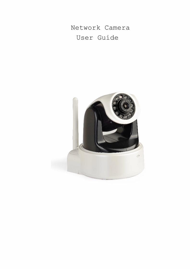
Network Camera
User Guide
Contents
Chapter I Product Introduction--
Chapter II Product Installation --
Chapter III Search equipment and login- --
Chapter IV Video attribute settings and
PTZ(Pan/Tilt/Zoom) control operations - --
Chapter V System Settings options - --
Chapter VI Front-End Record- --
Chapter VII Alarm settings - --
Chapter VIII Control panel- --
Chapter IX Diagnostic Tools - --
Chapter X Logout –
Chapter XI How to Access IP camera via WAN(Wide
Area Network)
Chapter XII How to Access IP Camera Through
Intelligent Mobile Phone
Chapter I Product Introduction--
Thank you to use wired/wireless IP Camera solution. IPCAM
is a electronic equipment which is able to transmit dynamic
video stream to all over the world through the network. The
user can always monitor the place he wants from anywhere, as
long as he is able to connect to Internet.
ASW IP camera works based on the TCP/IP standard. A WEB
server is integrated inside which can support Internet
Explorer. And this feature can help you to accomplish online
management and maintenance on your device simply, such as
remote configuration, remote start-up and firmware upgrade.
You can use the IPCAM monitoring homes, offices, factories,
stores, nurseries and etc, simply, conveniently and
real-time.
1.1 Hardware/Software requirements:
To use the computer-camera through networks, the minimum
hardware requirements of your computer should be met,
1. Pentium III CPU or better, 1GHz or higher frequency;
2. At least 256M memory;
3. windows xp, windows 7, 2000 or above operation system
Internet explorer version 4.0 or above, IE 6.0 is strongly
recommended.
1.2 Product features:
Simple installation: It is very simple to install IP
cameras. If you choose wired networking solution, you only
need to prepare power and networks connection. If you want
to use WIFI wireless connection, only power is a must.This
ip camera support WPS function,user can connect the router
and ip camera by entering the button on ip camera and
router ,and do not use the password to connect the router.
Scope of applications: Apply to homes, offices,
enterprises, supermarkets, schools and other public places.
Supporting multiple protocols: Embedded operation system
supports the TCP / IP, SMTP (simple mail protocol), HTTP, UPNP,
etc.
Simple configuration: Standard Web browser GUI can help
users to control and manage the IP cameras through LAN or
Internet.
Video Watching and Video Record: Provide concise GUI for
user to watch real-time video stream from anywhere networking
connection is available. And the video segments can be
recorded on your computer.
Alarm Monitoring: Through external alarm device, the alarm
information can be sent to your e-box or your mobile phone.
Especially, user can activate motion detection function to
detect any movement in the selected area. If any illegal
invasion happens, alarm will be realized. Simultaneously, the
captured images will be sent to email address specified by
user.
Support dynamic DNS: Support Dynamic DNS. Users can access
his/her IP cameras easily through DDNS despite that the camera
IP changes frequently.
Simple User Authority Management: Setting USER and
PASSWORD of the system can help user to protect privacy
effectively, meanwhile, users can be authorized with
different permission levels to operate the IP camera.
Real-time Monitor through Intelligent Mobile Phone: With
the assistance of professional client software IP Cam Viewer,
user can access any online IP Camera anywhere through
intelligent mobile phone, iPhone or Android-OS(Operation
System) based mobile phone and run routine PTZ operations.
User can download IP Cam Viewer software from CD delivered
in package box to your intelligent mobile phone. Please
confirm your mobile phone has iPhone OS or Android-OS and
choose the correct software version.
1.3 Packing list:
●IP Camera
●CDROM(include user guide, control, search equipment)
●Power adapter
●bracket
1.4 Interfaces
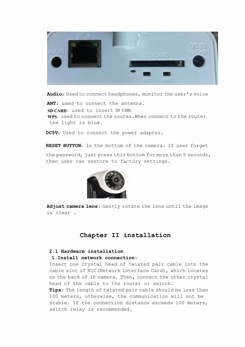
Audio::::Used to connect headphones, monitor the user's voice
ANT: used to connect the antenna.
SD CARD: used to insert SD CARD.
WPS: used to connect the router.When connect to the router,
the light is blue.
DC5V:Used to connect the power adapter.
RESET BUTTON:In the bottom of the camera. If user forget
the password, just press this bottom for more than 5 seconds,
then user can restore to factory settings.
Adjust camera lens: Gently rotate the lens until the image
is clear .
Chapter II installation
2.1 Hardware installation
1.Install network connection:
Insert one crystal head of twisted pair cable into the
cable slot of NIC(Network Interface Card), which locates
on the back of IP camera. Then, connect the other crystal
head of the cable to the router or switch.
Tips: The length of twisted pair cable should be less than
100 meters, otherwise, the communication will not be
stable. If the connection distance exceeds 100 meters,
switch relay is recommended.
2. Connect the power
Connect the IP camera with power slot through power
cable distributed in the package box.
Cautions: Please use the original power adaptor
distributed with the camera device, otherwise, it may
cause hardware damage.
3. Check the network indicator light
When the camera works, normally the green indicator of
the IP camera is on continuously and yellow light flashes.
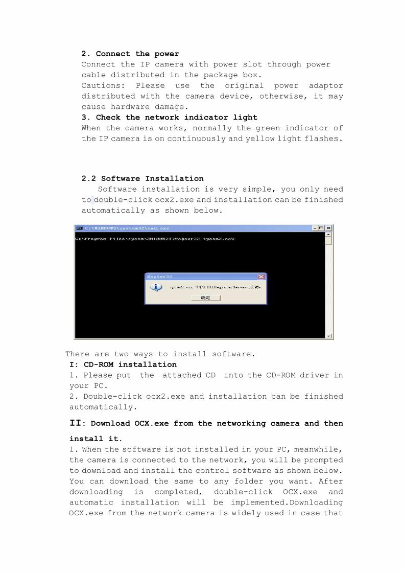
2.2 Software Installation
Software installation is very simple, you only need
to double-click ocx2.exe and installation can be finished
automatically as shown below.
There are two ways to install software.
I: CD-ROM installation
1. Please put the attached CD into the CD-ROM driver in
your PC.
2. Double-click ocx2.exe and installation can be finished
automatically.
II: Download OCX.exe from the networking camera and then
install it.
1. When the software is not installed in your PC, meanwhile,
the camera is connected to the network, you will be prompted
to download and install the control software as shown below.
You can download the same to any folder you want. After
downloading is completed, double-click OCX.exe and
automatic installation will be implemented.Downloading
OCX.exe from the network camera is widely used in case that
installation CD is not available.
Chapter III Search equipment and log into the
network camera
3.1:Search Ip camera in LAN
NOTES:
1: Make sure the equipment is properly connected with the
network and power.
2: The router must support DHCP (Dynamic Host Configuration
Protocol), because dynamic IP addresses obtaining is one of
the factory settings of camera. If the device cannot get the
correct ip address, it will use the default ip address.
3: The camera cannot be immediately used when power connection
is OK, system initialization will cost more than 20 seconds.
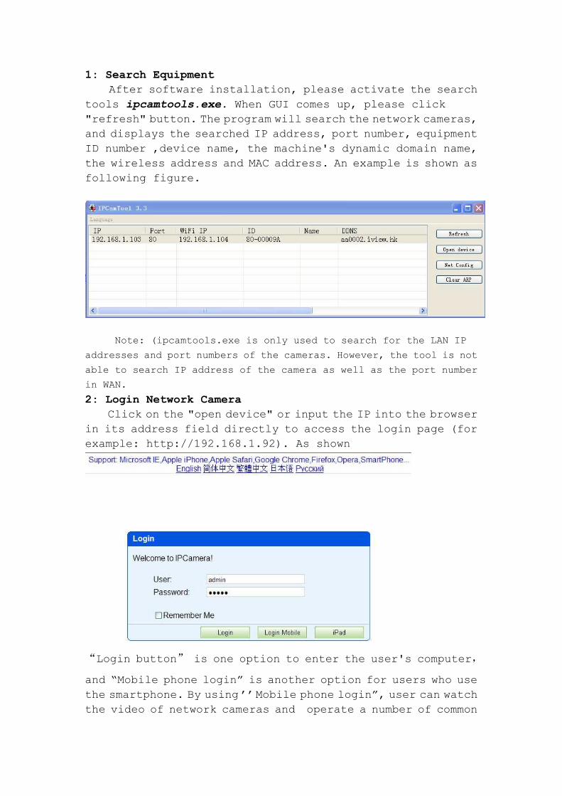
1: Search Equipment
After software installation, please activate the search
tools ipcamtools.exe. When GUI comes up, please click
"refresh" button. The program will search the network cameras,
and displays the searched IP address, port number, equipment
ID number ,device name, the machine's dynamic domain name,
the wireless address and MAC address. An example is shown as
following figure.
Note: (ipcamtools.exe is only used to search for the LAN IP
addresses and port numbers of the cameras. However, the tool is not
able to search IP address of the camera as well as the port number
in WAN.
2: Login Network Camera
Click on the "open device" or input the IP into the browser
in its address field directly to access the login page (for
example: http://192.168.1.92). As shown
“Login button” is one option to enter the user's computer,
and “Mobile phone login” is another option for users who use
the smartphone. By using ’’Mobile phone login”, user can watch
the video of network cameras and operate a number of common
features of the network camera. User can click “ipad” button
to login the IP Camera console if he wants to watch the online
video stream and operate the IP camera through iPad. When login,
user can select the appropriate language version on the upper
left corner
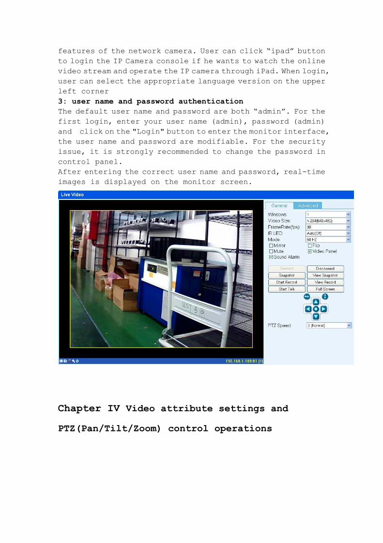
3: user name and password authentication
The default user name and password are both “admin”. For the
first login, enter your user name (admin), password (admin)
and click on the "Login" button to enter the monitor interface,
the user name and password are modifiable. For the security
issue, it is strongly recommended to change the password in
control panel.
After entering the correct user name and password, real-time
images is displayed on the monitor screen.
Chapter IV Video attribute settings and
PTZ(Pan/Tilt/Zoom) control operations
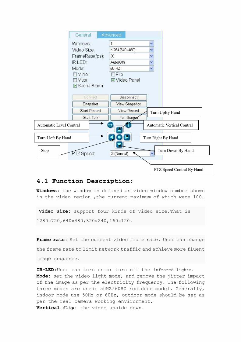
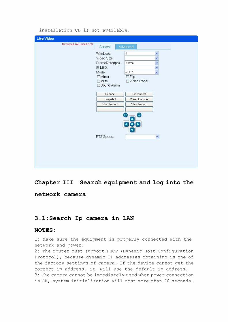
4.1 Function Description:
Windows: the window is defined as video window number shown
in the video region ,the current maximum of which were 100.
Video Size: support four kinds of video size.That is
1280x720,640x480,320x240,160x120.
Frame rate: Set the current video frame rate. User can change
the frame rate to limit network traffic and achieve more fluent
image sequence.
IR-LED:User can turn on or turn off the infrared lights.
Mode: set the video light mode, and remove the jitter impact
of the image as per the electricity frequency. The following
three modes are used: 50HZ/60HZ /outdoor model. Generally,
indoor mode use 50Hz or 60Hz, outdoor mode should be set as
per the real camera working environment.
Vertical flip: the video upside down.
Automatic Level Contral Automatic Vertical Contral
Turn Right By Hand Turn Lleft By Hand
Turn UpBy Hand
Turn Down By Hand Stop
PTZ Speed Contral By Hand
Horizontal flip: Reverse the video.
Mute: Close the sound of the ip camera.
Video Panel: Shortcut function keys will be displayed on
monitor screen, which can take photos, video and realize the
function of voice intercom .
Sound Alarm: If selected, when the alarm device is triggered,
computer sound alarm. If not, computer is mute.
Stretch:stretch the image to the full window.
OSD:Add time stamp to the video.
Connection: Connect the selected device address, and display
images in the current window
Disconnect: Disconnect the selected video connection, and stop
displaying video. If video recording is ongoing, the operation
will stop simultaneously.
Snapshot.: Photograph the selected device and save the photographed
image.
View Snapshot: Open image folder to view the pictures.
Start/Stop the video record: Start or stop the video record
of the selected device.
Start/Stop all of the video record: Start or stop the video
record of all the connected devices.
View Record: Open video folder and view the saved video
segments.
Start Talk: Used for users who want to talk thought internet.
Full screen:Monitor screen is full screen, in order to view
easily.
PTZ speed: User can control the PTZ speed according to need
Ptz preset:None.
Video operation interface is shown as follows:
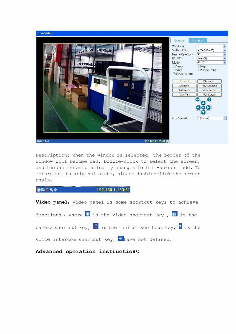
Description: when the window is selected, the border of the
window will become red. Double-click to select the screen,
and the screen automatically changes to full-screen mode. To
return to its original state, please double-click the screen
again.
Video panel;;;;Video panel is some shortcut keys to achieve
functions ,where is the video shortcut key , is the
camera shortcut key, is the monitor shortcut key, is the
voice intercom shortcut key, have not defined.
Advanced operation instructions:
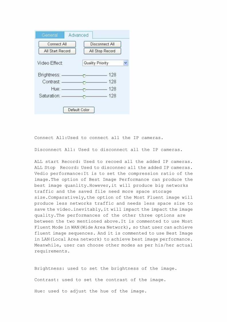
Connect All:Used to connect all the IP cameras.
Disconnect All: Used to disconnect all the IP cameras.
ALL start Record: Used to recoed all the added IP cameras.
ALL Stop Record: Used to disconnec all the added IP cameras.
Vedio performance:It is to set the compression ratio of the
image.The option of Best Image Performance can produce the
best image quanlity.However,it will produce big networks
traffic and the saved file need more space storage
size.Comparatively,the option of the Most Fluent image will
produce less networks traffic and needs less space size to
save the video.inevitably,it will impact the impact the image
quality.The performances of the other three options are
between the two mentioned above.It is commented to use Most
Fluent Mode in WAN(Wide Area Network), so that user can achieve
fluent image sequences. And it is commented to use Best Image
in LAN(Local Area network) to achieve best image performance.
Meanwhile, user can choose other modes as per his/her actual
requirements.
Brightness: used to set the brightness of the image.
Contrast: used to set the contrast of the image.
Hue: used to adjust the hue of the image.
Saturation: used to adjust the saturation of the image.
Default Parameters: set the default parameters of the image,
recommend to use default parameters.
Chapter V System Settings Options
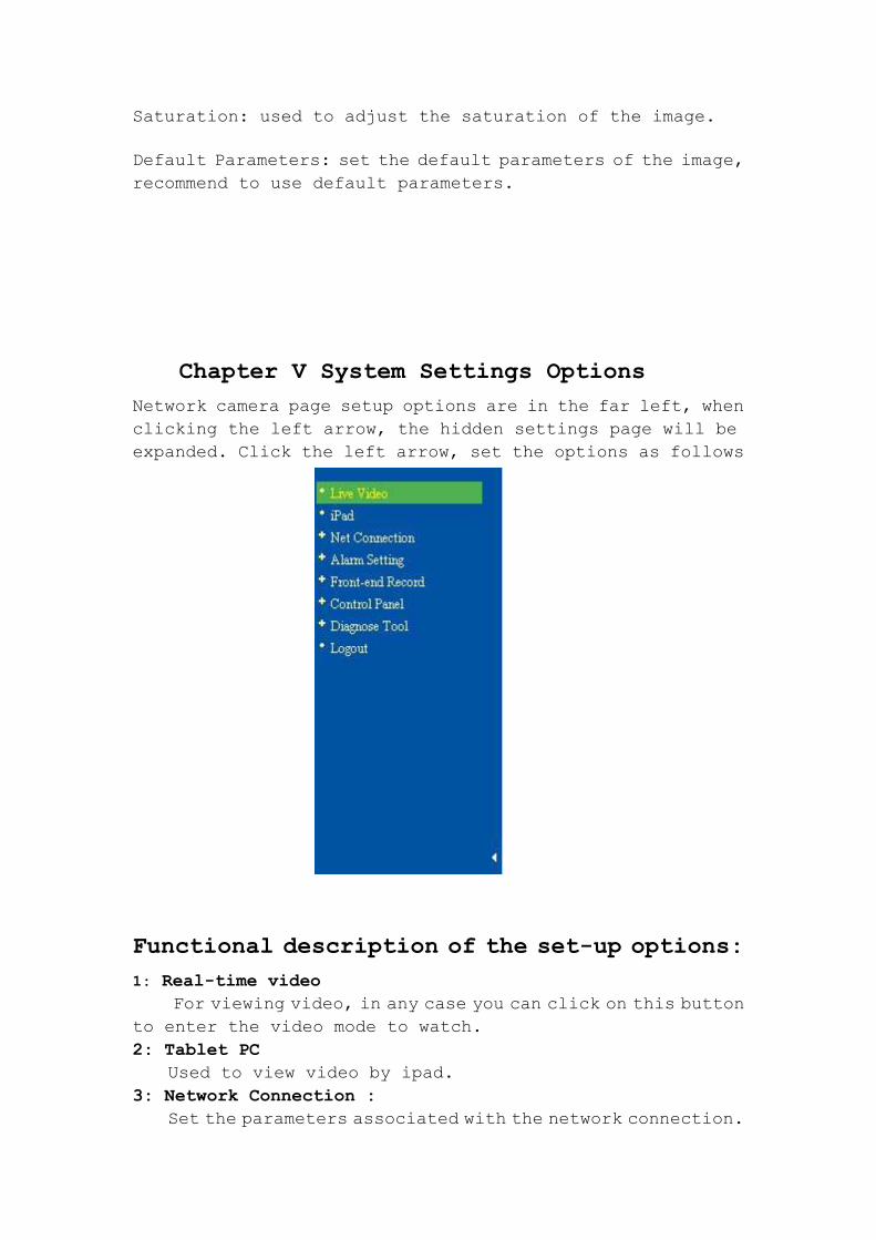
Network camera page setup options are in the far left, when
clicking the left arrow, the hidden settings page will be
expanded. Click the left arrow, set the options as follows
Functional description of the set-up options:
1: Real-time video
For viewing video, in any case you can click on this button
to enter the video mode to watch.
2: Tablet PC
Used to view video by ipad.
3: Network Connection :
Set the parameters associated with the network connection.
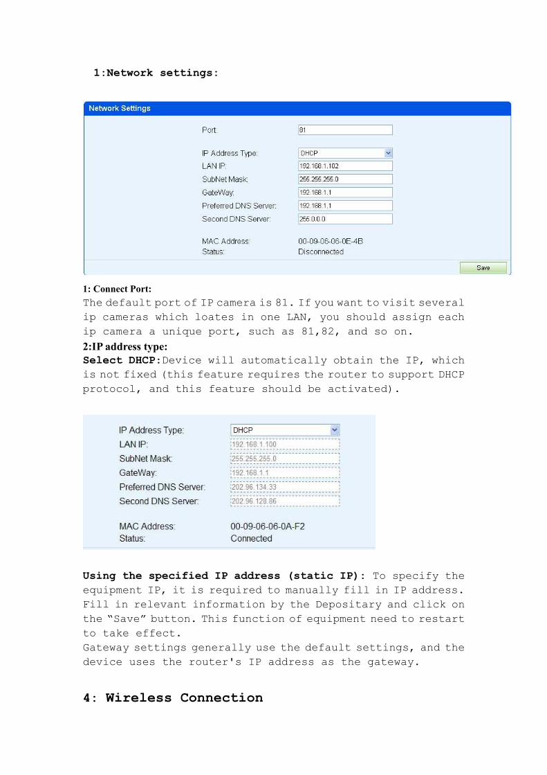
1:Network settings:
1: Connect Port:
The default port of IP camera is 81. If you want to visit several
ip cameras which loates in one LAN, you should assign each
ip camera a unique port, such as 81,82, and so on.
2:IP address type: Select DHCP:Device will automatically obtain the IP, which
is not fixed (this feature requires the router to support DHCP
protocol, and this feature should be activated).
Using the specified IP address (static IP): To specify the
equipment IP, it is required to manually fill in IP address.
Fill in relevant information by the Depositary and click on
the “Save” button. This function of equipment need to restart
to take effect.
Gateway settings generally use the default settings, and the
device uses the router's IP address as the gateway.
4: Wireless Connection
1. WPS function is supported in IP Cam. User can make the
connection between IP cam and wireless router with WPS
function by simply pressing the WPS button on the IP cam,
without the process of setting passwords. If user presses the
WPS button on the back of the device, the WPS verification
web page will dispalyed. It will give user the notice of
encryption successu after WPS verification is finished.
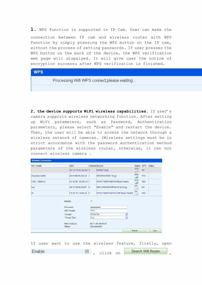
2, the device supports WiFi wireless capabilities. If user’s
camera supports wireless networking function. After setting
up WiFi parameters, such as Password, Authentication
parameters, please select "Enable" and restart the device.
Then, the user will be able to access the network through a
wireless network of cameras. (Wireless settings must be in
strict accordance with the password authentication method
parameters of the wireless router, otherwise, it can not
connect wireless camera .
If user want to use the wireless feature, firstly, open
, click on ,
search for your area wireless router; secondly, choose the
router name of user itself and fill in the wireless router
password and the type of IP address .Generally, user can
connect to the router now. Unplug the network cable at this
moment, you should find the ip camera. Network camera supports
WEP and WPA2 encryption. As the diversity of the router, if
one encryption way is not connected on the router, the user
should try to connect to another encryption method.
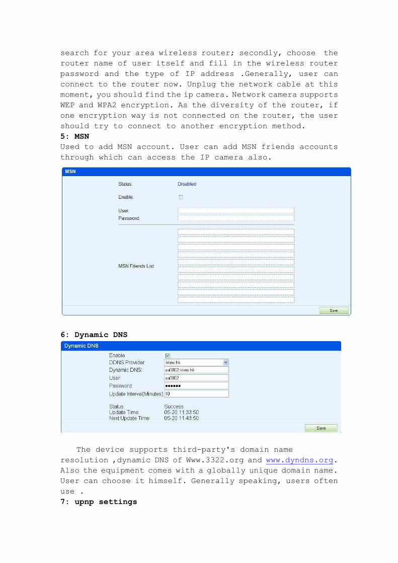
5: MSN
Used to add MSN account. User can add MSN friends accounts
through which can access the IP camera also.
6: Dynamic DNS
The device supports third-party's domain name
resolution ,dynamic DNS of Www.3322.org and www.dyndns.org.
Also the equipment comes with a globally unique domain name.
User can choose it himself. Generally speaking, users often
use .
7: upnp settings

Upnp is to realize automatic port mapping function. If the
camera is connected to a router. In order to access to the
cameras through WAN, it is required to open a specified port
of the router to the camera. (This feature requires router
support, and this feature should be open. Without this feature,
you need to manually set up port mapping in the router). If
the upnp enabled successfully, the below figure will be
displayed.
8888:::: PortPortPortPort Settings Settings Settings Settings
The default port allocated to the IP camera is 81.
9: Reverse connect
Usually, in networks, IP camera is set as server, and monitor
software plays the role of client. But in case that IP camera
locates in the network which doesn’t support server settings.
Reverse connect function can help the user set the IP camera
as client and set the monitor software as server, so that user
can access the IP camera through monitor software.
Chapter V alarm settings
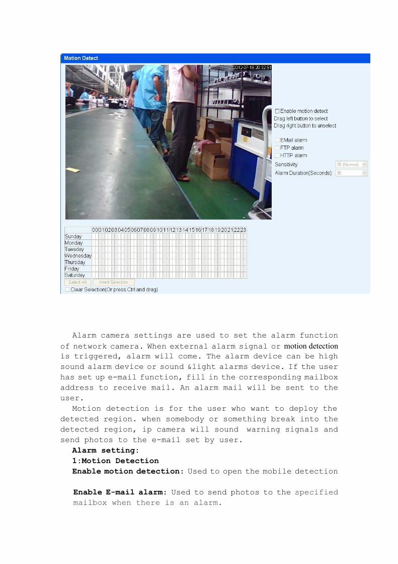
Alarm camera settings are used to set the alarm function
of network camera. When external alarm signal or motion detection
is triggered, alarm will come. The alarm device can be high
sound alarm device or sound &light alarms device. If the user
has set up e-mail function, fill in the corresponding mailbox
address to receive mail. An alarm mail will be sent to the
user.
Motion detection is for the user who want to deploy the
detected region. when somebody or something break into the
detected region, ip camera will sound warning signals and
send photos to the e-mail set by user.
Alarm setting:
1:Motion Detection
Enable motion detection: Used to open the mobile detection
Enable E-mail alarm: Used to send photos to the specified
mailbox when there is an alarm.
Enable FTP alarm: Used to send photos to FTP specified
server. when there is an alarm.
Enable HTTP alarm: Used to send messages to HTTP site when
there is an alarm.
Sensitivity: For motion detection sensitivity, the smaller
the value is, the higher the sensitivity is. Usually, user
use default value. And also sensitivity can be set by user
itself.
Alarm Duration(Sesconds):you can choose the time of the
alarm duration.
2:E-mail alarm: When external input IO alarm probe is closed,
it will trigger the alarm message, and send the current
photos to the specified mailbox.
3::::FTP: When external input IO alarm probe is closed, it
will trigger the alarm message, and send the current photos
to the FTP site set by user.
4:HTTP alarm: When external input IO alarm probe is closed,
it will trigger the alarm message, and send the current
messages to the HTTP site set by user.
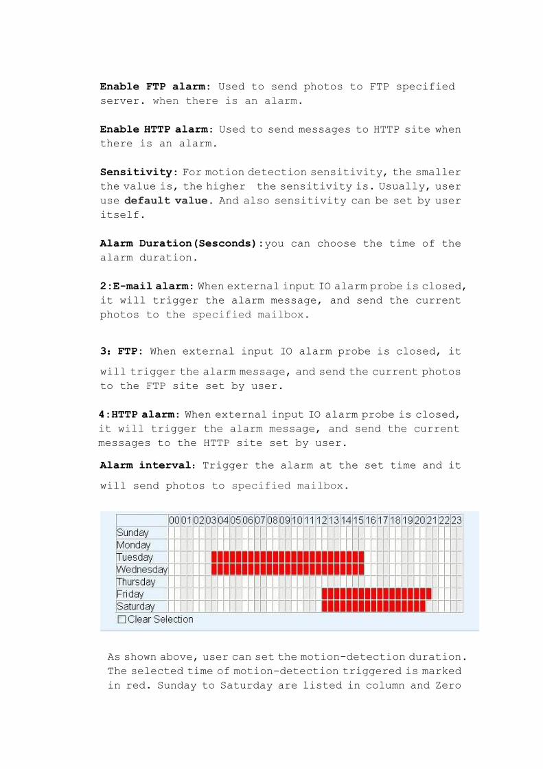
Alarm interval:Trigger the alarm at the set time and it
will send photos to specified mailbox.
As shown above, user can set the motion-detection duration.
The selected time of motion-detection triggered is marked
in red. Sunday to Saturday are listed in column and Zero
O’clock to 23 O’clock are listed in row. In the selected
detecting time, if any motion is detected, alarm will be
trigger.
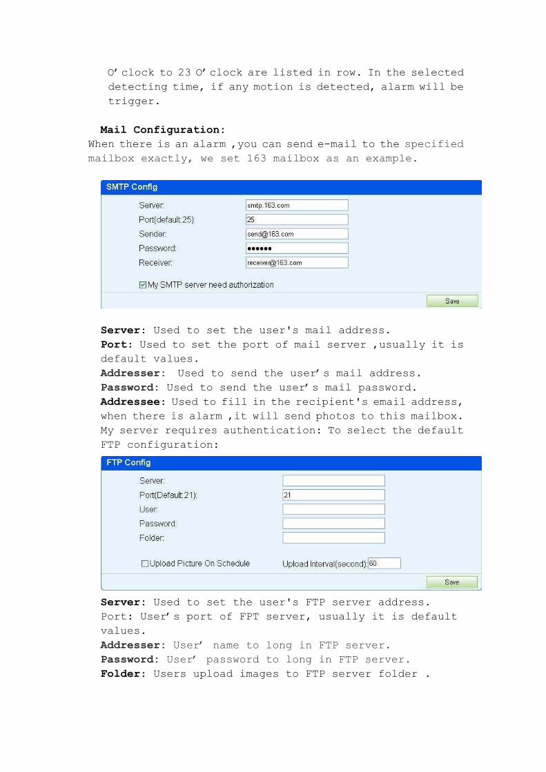
Mail Configuration:
When there is an alarm ,you can send e-mail to the specified
mailbox exactly, we set 163 mailbox as an example.
Server: Used to set the user's mail address.
Port: Used to set the port of mail server ,usually it is
default values.
Addresser: Used to send the user’s mail address.
Password: Used to send the user’s mail password.
Addressee: Used to fill in the recipient's email address,
when there is alarm ,it will send photos to this mailbox.
My server requires authentication: To select the default
FTP configuration:
Server: Used to set the user's FTP server address.
Port: User’s port of FPT server, usually it is default
values.
Addresser: User’ name to long in FTP server.
Password: User’ password to long in FTP server.
Folder: Users upload images to FTP server folder .
HTTP Alarm Configuration: When an alarm is triggered, alarm
information will be send to the user's HTTP site. Set as
follows:
Chapter VI Front-end Record
Front-End record means that user can save the video into the SD card inserted in IP cam as his/her configurations.
Meanwhile, user can access the video directly from SD card,
or download the video through networks.
Note:If user find the capacity of the inserted SD card
displayed on ip camera less than the actual capacity,please
format the SD card as NTFS,or Ip camera cannot identify the
capacity of more than 2 GB card.
FAT32 format cannnot identify more that 2GB card.
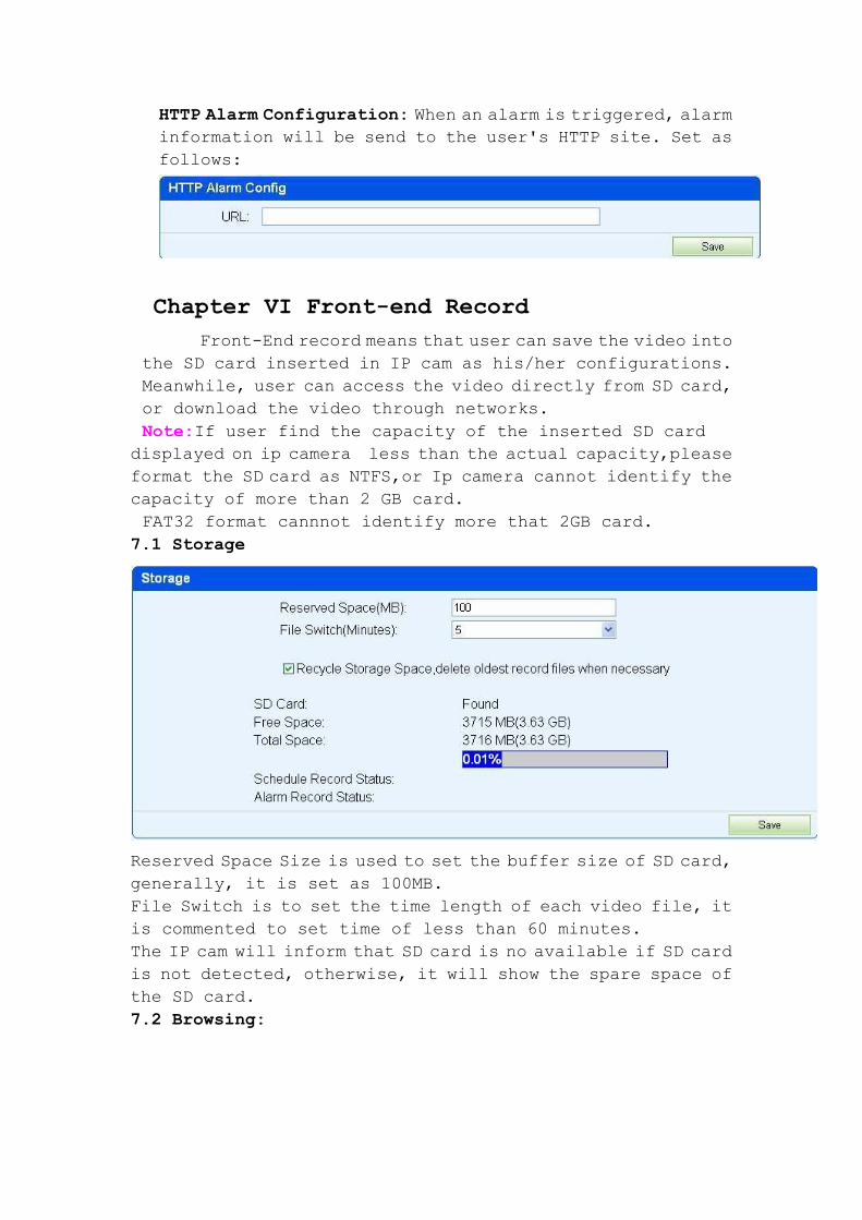
7.1 Storage
Reserved Space Size is used to set the buffer size of SD card,
generally, it is set as 100MB.
File Switch is to set the time length of each video file, it
is commented to set time of less than 60 minutes.
The IP cam will inform that SD card is no available if SD card
is not detected, otherwise, it will show the spare space of
the SD card.
7.2 Browsing:
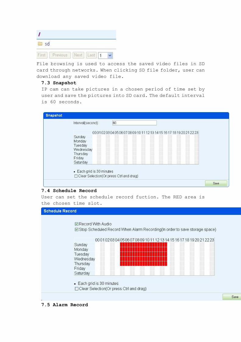
File browsing is used to access the saved video files in SD
card through networks. When clicking SD file folder, user can
download any saved video file.
7.3 Snapshot
IP cam can take pictures in a chosen period of time set by
user and save the pictures into SD card. The default interval
is 60 seconds.
7.4 Schedule Record
User can set the schedule record fuction. The RED area is
the chosen time slot.
7.5 Alarm Record
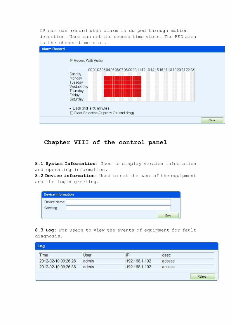
IP cam can record when alarm is dumped through motion
detection. User can set the record time slots. The RED area
is the chosen time slot.
Chapter VIII of the control panel
8.1 System Information: Used to display version information
and operating information.
8.2 Device information: Used to set the name of the equipment
and the login greeting.
8.3 Log: For users to view the events of equipment for fault
diagnosis.
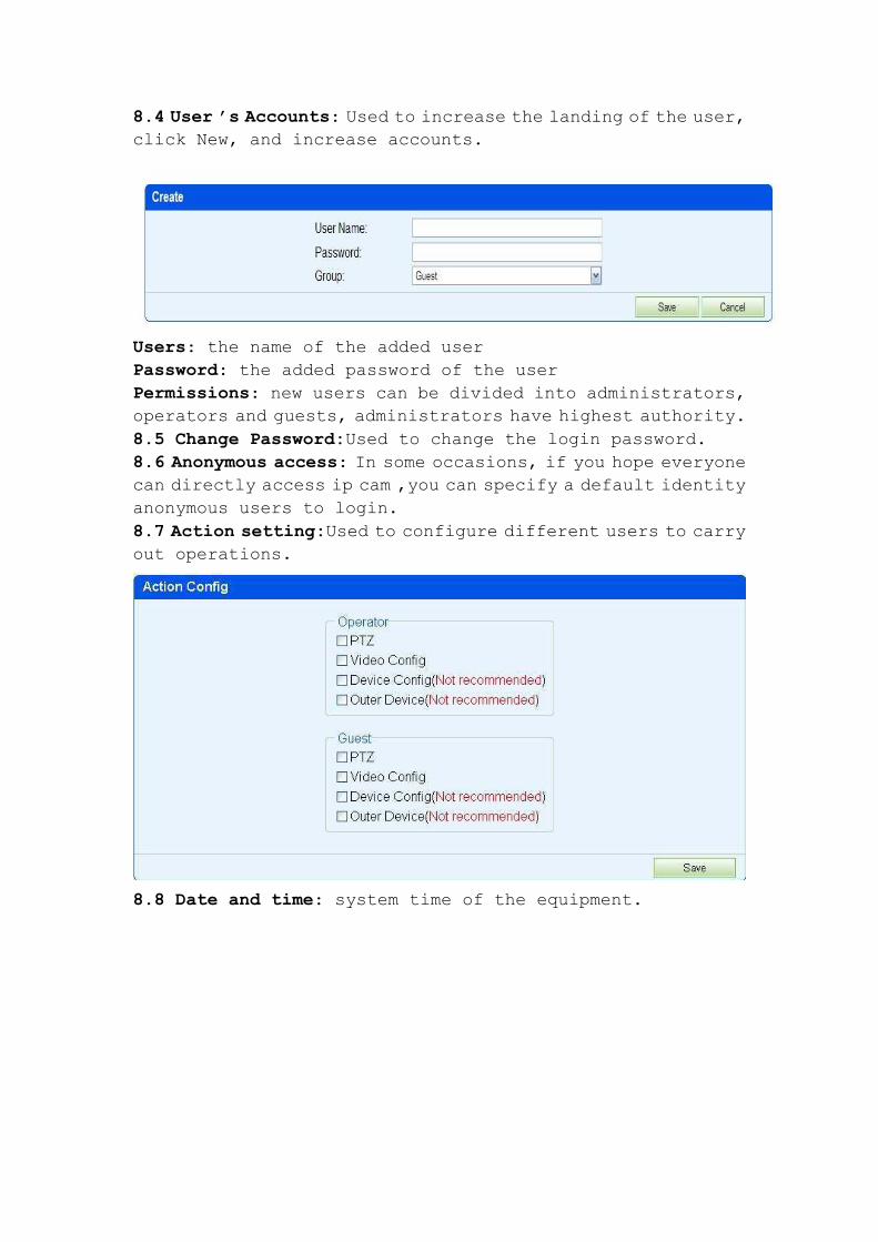
8.4 User ’s Accounts: Used to increase the landing of the user,
click New, and increase accounts.
Users: the name of the added user
Password: the added password of the user
Permissions: new users can be divided into administrators,
operators and guests, administrators have highest authority.
8.5 Change Password:Used to change the login password.
8.6 Anonymous access: In some occasions, if you hope everyone
can directly access ip cam ,you can specify a default identity
anonymous users to login.
8.7 Action setting:Used to configure different users to carry
out operations.
8.8 Date and time: system time of the equipment.
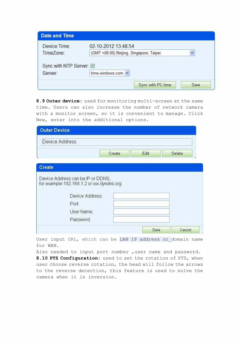
8.9 Outer device: used for monitoring multi-screen at the same
time. Users can also increase the number of network camera
with a monitor screen, so it is convenient to manage. Click
New, enter into the additional options.
User input URL, which can be LAN IP address or domain name
for WAN.
Also needed to input port number ,user name and password.
8.10 PTZ Configuration: used to set the rotation of PTZ, when
user choose reverse rotation, the head will follow the arrows
to the reverse detection, this feature is used to solve the
camera when it is inversion.
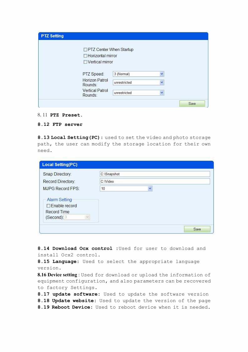
8.11 PTZ Preset.
8.12 FTP server
8.13 Local Setting(PC): used to set the video and photo storage
path, the user can modify the storage location for their own
need.
8.14 Download Ocx control :Used for user to download and
install Ocx2 control.
8.15 Language: Used to select the appropriate language
version.
8.16 Device setting : Used for download or upload the information of
equipment configuration, and also parameters can be recovered
to factory Settings.
8.17 update software: Used to update the software version
8.18 Update website: Used to update the version of the page
8.19 Reboot Device: Used to reboot device when it is needed.
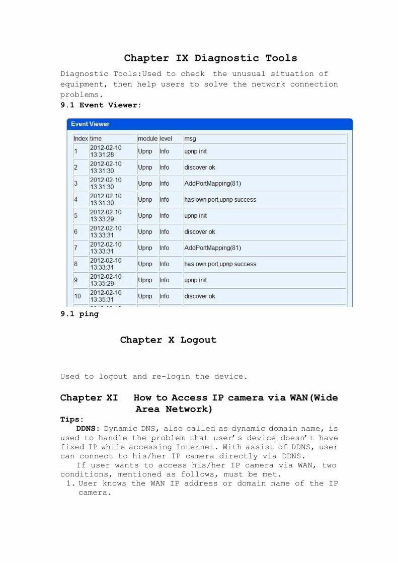
Chapter IX Diagnostic Tools
Diagnostic Tools:Used to check the unusual situation of
equipment, then help users to solve the network connection
problems.
9.1 Event Viewer:
9.1 ping
Chapter X Logout
Used to logout and re-login the device.
Chapter XI How to Access IP camera via WAN(Wide Area Network)
Tips: DDNS: Dynamic DNS, also called as dynamic domain name, is
used to handle the problem that user’s device doesn’t have
fixed IP while accessing Internet. With assist of DDNS, user
can connect to his/her IP camera directly via DDNS.
If user wants to access his/her IP camera via WAN, two
conditions, mentioned as follows, must be met.
1. User knows the WAN IP address or domain name of the IP
camera.
2. If IP camera connects to a router, the corresponding mirror
port of router must be set for IP camera, so that user
can access the IP Cam located in LAN through WAN.
Most users don’t have fixed IPs. Every time when the device
connects with Internet, networking service operator allocates
a dynamic IP to the device. If the connection breaks and
rebuilds, a new IP will be allocated again. Normally, user
doesn’t know the IP of device. DDNS feature can overcome this
problem. As long as user knows the dynamic domain name, he/she
is always able to access his/her networking device.
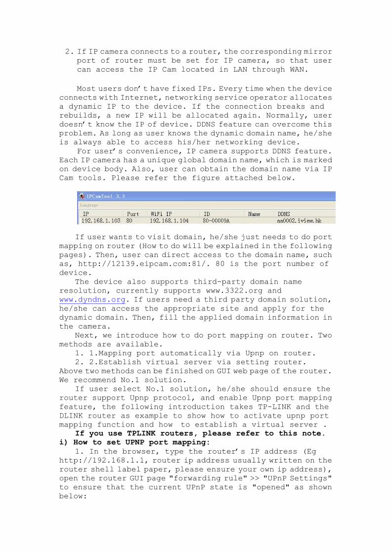
For user’s convenience, IP camera supports DDNS feature.
Each IP camera has a unique global domain name, which is marked
on device body. Also, user can obtain the domain name via IP
Cam tools. Please refer the figure attached below.
If user wants to visit domain, he/she just needs to do port
mapping on router (How to do will be explained in the following
pages). Then, user can direct access to the domain name, such
as, http://12139.eipcam.com:81/. 80 is the port number of
device.
The device also supports third-party domain name
resolution, currently supports www.3322.org and
www.dyndns.org. If users need a third party domain solution,
he/she can access the appropriate site and apply for the
dynamic domain. Then, fill the applied domain information in
the camera.
Next, we introduce how to do port mapping on router. Two
methods are available.
1. 1.Mapping port automatically via Upnp on router.
2. 2.Establish virtual server via setting router.
Above two methods can be finished on GUI web page of the router.
We recommend No.1 solution.
If user select No.1 solution, he/she should ensure the
router support Upnp protocol, and enable Upnp port mapping
feature, the following introduction takes TP-LINK and the
DLINK router as example to show how to activate upnp port
mapping function and how to establish a virtual server .
If you use TPLINK routers, please refer to this note. i) How to set UPNP port mapping:
1. In the browser, type the router’s IP address (Eg
http://192.168.1.1, router ip address usually written on the
router shell label paper, please ensure your own ip address),
open the router GUI page "forwarding rule" >> "UPnP Settings"
to ensure that the current UPnP state is "opened" as shown
below:
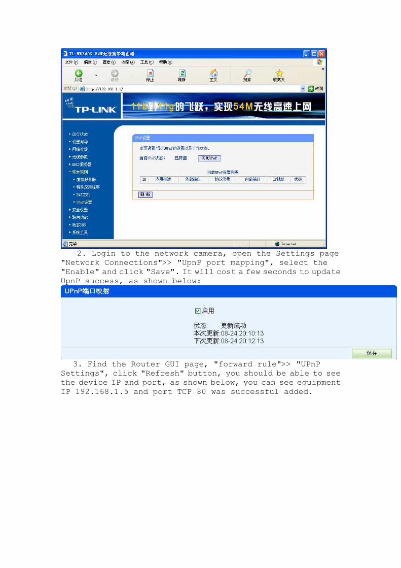
2. Login to the network camera, open the Settings page
"Network Connections">> "UpnP port mapping", select the
"Enable" and click "Save". It will cost a few seconds to update
UpnP success, as shown below:
3. Find the Router GUI page, "forward rule">> "UPnP
Settings", click "Refresh" button, you should be able to see
the device IP and port, as shown below, you can see equipment
IP 192.168.1.5 and port TCP 80 was successful added.
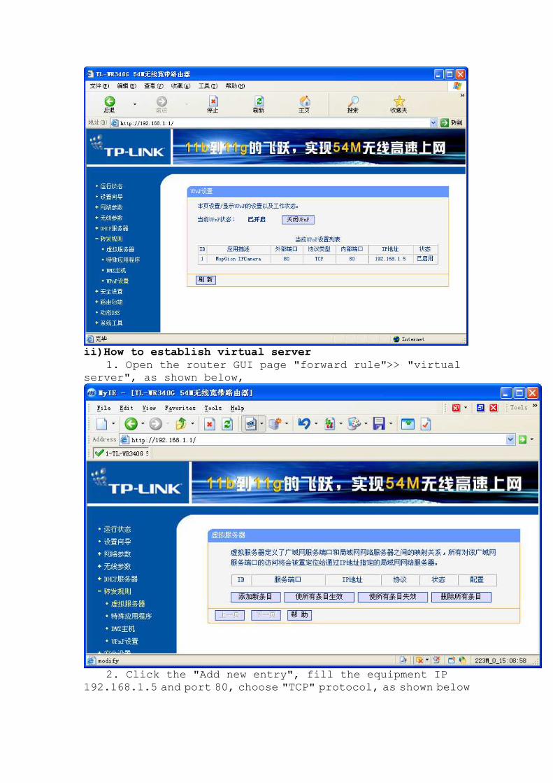
ii)How to establish virtual server
1. Open the router GUI page "forward rule">> "virtual
server", as shown below,
2. Click the "Add new entry", fill the equipment IP
192.168.1.5 and port 80, choose "TCP" protocol, as shown below
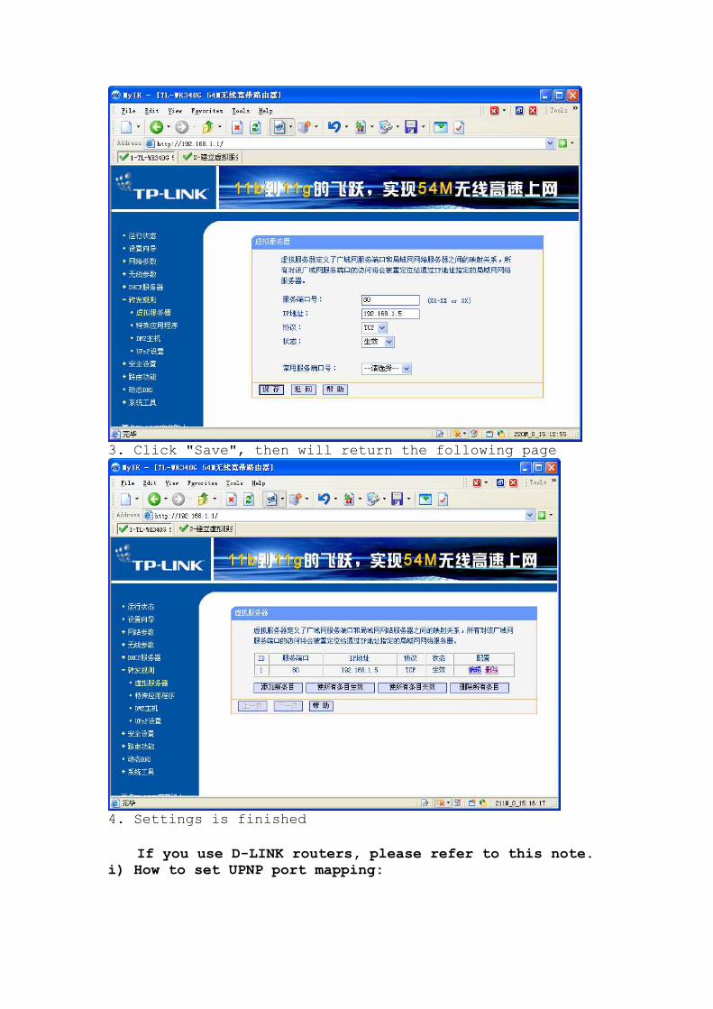
3. Click "Save", then will return the following page
4. Settings is finished
If you use D-LINK routers, please refer to this note.
i) How to set UPNP port mapping:
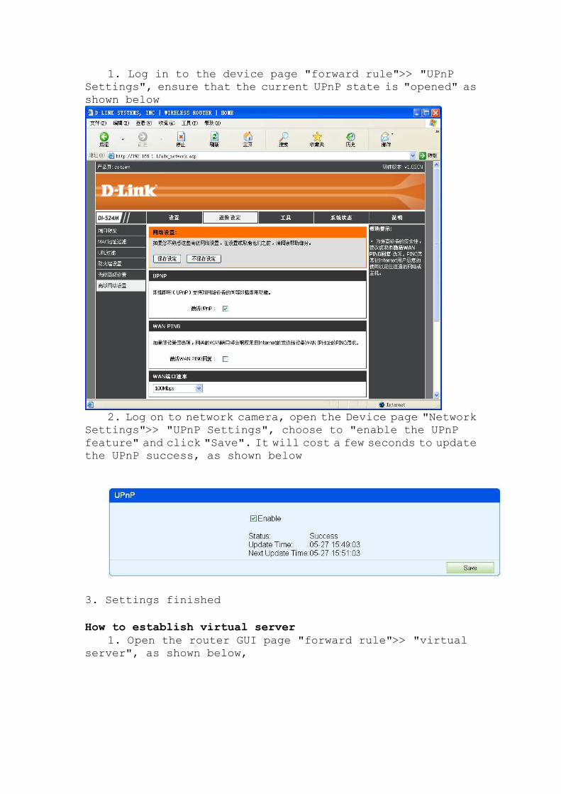
1. Log in to the device page "forward rule">> "UPnP
Settings", ensure that the current UPnP state is "opened" as
shown below
2. Log on to network camera, open the Device page "Network
Settings">> "UPnP Settings", choose to "enable the UPnP
feature" and click "Save". It will cost a few seconds to update
the UPnP success, as shown below
3. Settings finished
How to establish virtual server
1. Open the router GUI page "forward rule">> "virtual
server", as shown below,
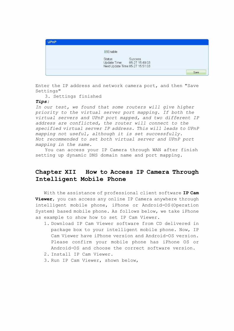
Enter the IP address and network camera port, and then "Save
Settings"
3. Settings finished
Tips:
In our test, we found that some routers will give higher
priority to the virtual server port mapping. If both the
virtual servers and UPnP port mapped, and two different IP
address are conflicted, the router will connect to the
specified virtual server IP address. This will leads to UPnP
mapping not useful, although it is set successfully.
Not recommended to set both virtual server and UPnP port
mapping in the same.
You can access your IP Camera through WAN after finish
setting up dynamic DNS domain name and port mapping.
Chapter XII How to Access IP Camera Through Intelligent Mobile Phone
With the assistance of professional client software IP Cam
Viewer, you can access any online IP Camera anywhere through
intelligent mobile phone, iPhone or Android-OS(Operation
System) based mobile phone. As follows below, we take iPhone
as example to show how to set IP Cam Viewer.
1. Download IP Cam Viewer software from CD delivered in
package box to your intelligent mobile phone. Now, IP
Cam Viewer have iPhone version and Android-OS version.
Please confirm your mobile phone has iPhone OS or
Android-OS and choose the correct software version.
2. Install IP Cam Viewer.
3. Run IP Cam Viewer, shown below,
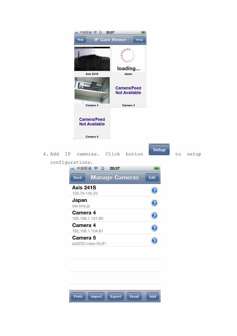
4. Add IP cameras. Click button to setup
configurations.
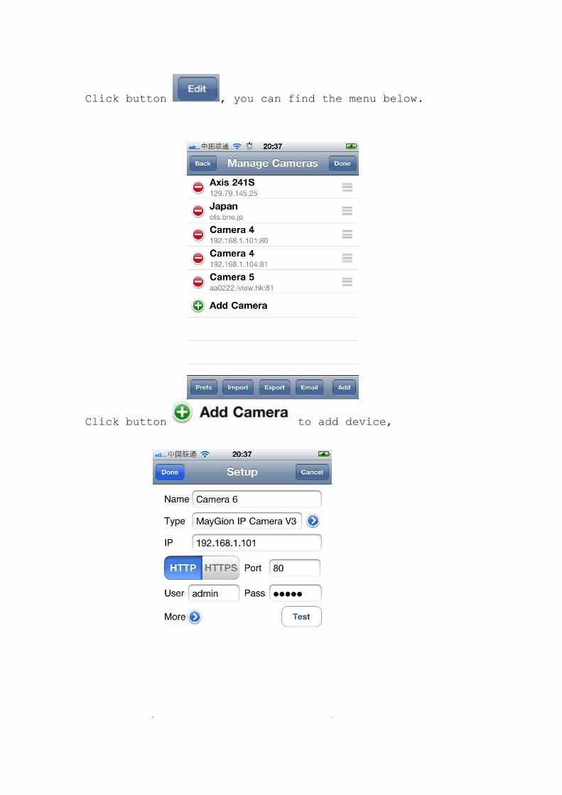
Click button , you can find the menu below.
Click button to add device,
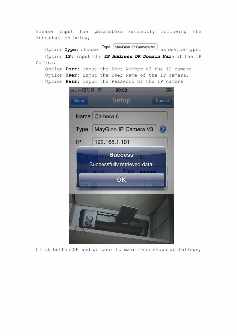
Please input the parameters correctly following the
introduction below,
Option Type: choose as device type.
Option IP: input the IP Address OR Domain Name of the IP
Camera.
Option Port: input the Port Number of the IP camera.
Option User: input the User Name of the IP camera.
Option Pass: input the Password of the IP camera
Click button OK and go back to main menu shown as follows,
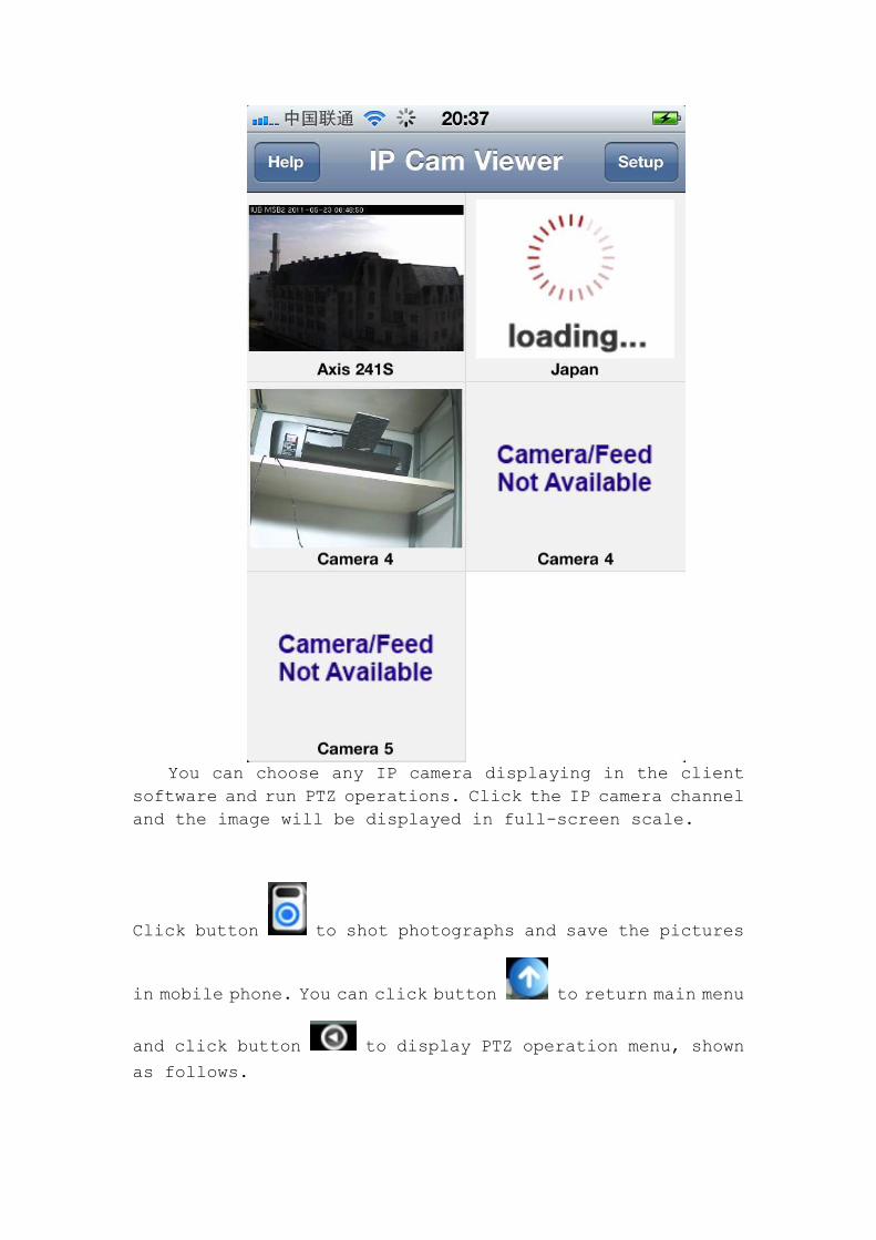
You can choose any IP camera displaying in the client
software and run PTZ operations. Click the IP camera channel
and the image will be displayed in full-screen scale.
Click button to shot photographs and save the pictures
in mobile phone. You can click button to return main menu
and click button to display PTZ operation menu, shown
as follows.
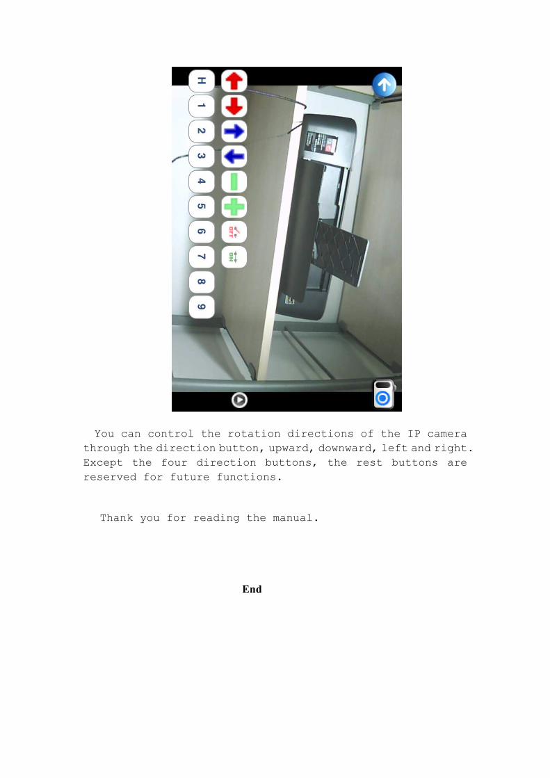
You can control the rotation directions of the IP camera
through the direction button, upward, downward, left and right.
Except the four direction buttons, the rest buttons are
reserved for future functions.
Thank you for reading the manual.
End