CMSC 611: Advanced Computer Architecture Shared Memory Most slides adapted from David Patterson....
47
CMSC 611: Advanced Computer Architecture Shared Memory Most slides adapted from David Patterson. Some from Mohome
-
Upload
roland-plank -
Category
Documents
-
view
215 -
download
1
Transcript of CMSC 611: Advanced Computer Architecture Shared Memory Most slides adapted from David Patterson....

CMSC 611: Advanced Computer Architecture
Shared Memory
Most slides adapted from David Patterson. Some from Mohomed Younis

Can support either SW model on either HW basis
MIMD
• Message Passing• Shared memory/distributed memory
– Uniform Memory Access (UMA)– Non-Uniform Memory Access (NUMA)

Message passing
• Processors have private memories, communicate via messages
• Advantages:– Less hardware, easier to design– Focuses attention on costly non-local
operations
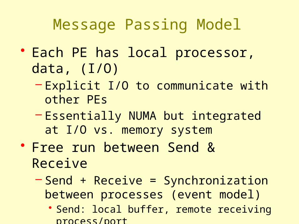
Message Passing Model
• Each PE has local processor, data, (I/O)– Explicit I/O to communicate with other PEs– Essentially NUMA but integrated at I/O vs.
memory system• Free run between Send & Receive
– Send + Receive = Synchronization between processes (event model)• Send: local buffer, remote receiving process/port• Receive: remote sending process/port, local
buffer
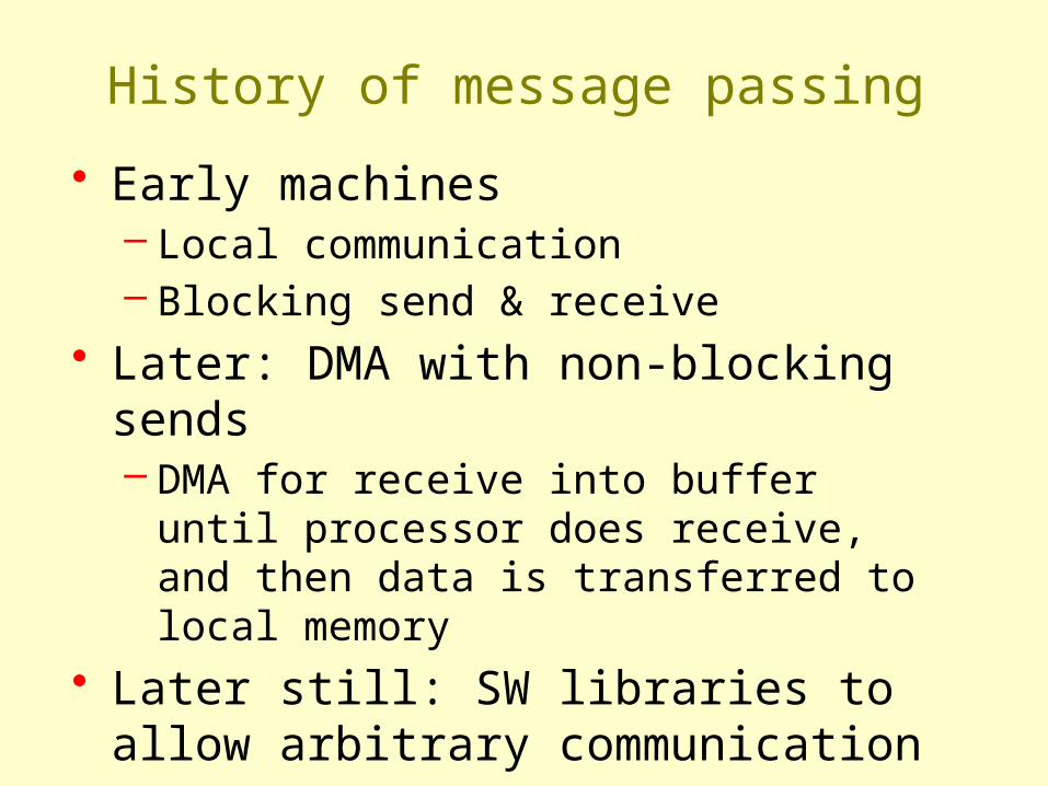
History of message passing
• Early machines– Local communication– Blocking send & receive
• Later: DMA with non-blocking sends– DMA for receive into buffer until processor
does receive, and then data is transferred to local memory
• Later still: SW libraries to allow arbitrary communication

Shared Memory
• Processors communicate with shared address space
• Easy on small-scale machines• Advantages:
– Model of choice for uniprocessors, small-scale multiprocessor
– Ease of programming– Lower latency– Easier to use hardware controlled caching
• Difficult to handle node failure

Centralized Shared Memory
• Processors share a single centralized (UMA) memory through a bus interconnect
• Feasible for small processor count to limit memory contention• Model for multi-core CPUs

Distributed Memory
• Uses physically distributed (NUMA) memory to support large processor counts (to avoid memory contention)
• Advantages– Allows cost-effective way to scale the memory bandwidth – Reduces memory latency
• Disadvantage– Increased complexity of communicating data

Shared Address Model
• Physical locations– Each PE can name every physical location
in the machine• Shared data
– Each process can name all data it shares with other processes

Shared Address Model
• Data transfer– Use load and store, VM maps to local or remote
location– Extra memory level: cache remote data– Significant research on making the translation
transparent and scalable for many nodes• Handling data consistency and protection challenging • Latency depends on the underlying hardware architecture
(bus bandwidth, memory access time and support for address translation)
• Scalability is limited given that the communication model is so tightly coupled with process address space

Three Fundamental Issues
• 1: Naming: how to solve large problem fast– what data is shared– how it is addressed– what operations can access data– how processes refer to each other
• Choice of naming affects code produced by a compiler– Just remember and load address or keep track of
processor number and local virtual address for message passing
• Choice of naming affects replication of data– In cache memory hierarchy or via SW replication
and consistency

Naming Address Spaces
• Global physical address space– any processor can generate, address and access it
in a single operation
• Global virtual address space– if the address space of each process can be
configured to contain all shared data of the parallel program• memory can be anywhere: virtual address translation
handles it
• Segmented shared address space– locations are named <process number, address>
uniformly for all processes of the parallel program

Three Fundamental Issues
• 2: Synchronization: To cooperate, processes must coordinate– Message passing is implicit coordination
with transmission or arrival of data– Shared address → additional operations to
explicitly coordinate: e.g., write a flag, awaken a thread, interrupt a processor

Three Fundamental Issues
• 3: Latency and Bandwidth– Bandwidth
• Need high bandwidth in communication• Cannot scale, but stay close• Match limits in network, memory, and processor• Overhead to communicate is a problem in many machines
– Latency• Affects performance, since processor may have to wait• Affects ease of programming, since requires more thought
to overlap communication and computation– Latency Hiding
• How can a mechanism help hide latency?• Examples: overlap message send with computation, pre-
fetch data, switch to other tasks

Centralized Shared Memory MIMD
• Processors share a single centralized memory through a bus interconnect– Memory contention: Feasible for small # processors– Caches serve to:
• Increase bandwidth versus bus/memory
• Reduce latency of access• Valuable for both private data
and shared data– Access to shared data is
optimized by replication• Decreases latency• Increases memory bandwidth• Reduces contention• Reduces cache coherence problems

A cache coherence problem arises when the cache reflects a view of memory which is different from reality
Cache Coherency
• A memory system is coherent if:– P reads X, P writes X, no other processor writes X, P reads X
• Always returns value written by P– P reads X, Q writes X, P reads X
• Returns value written by Q (provided sufficient W/R separation)– P writes X, Q writes X
• Seen in the same order by all processors
Potential HW Coherency Solutions
• Snooping Solution (Snoopy Bus)– Send all requests for data to all processors– Processors snoop to see if they have a copy
and respond accordingly – Requires broadcast, since caching
information is at processors– Works well with bus (natural broadcast
medium)– Dominates for small scale machines (most
of the market)

Potential HW Coherency Solutions
• Directory-Based Schemes– Keep track of what is being shared in one
centralized place– Distributed memory distributed directory ⇒
for scalability (avoids bottlenecks)– Send point-to-point requests to processors
via network– Scales better than Snooping– Actually existed before Snooping-based
schemes

Basic Snooping Protocols• Write Invalidate Protocol:
– Write to shared data: an invalidate is sent to all caches which snoop and invalidate any copies
– Cache invalidation will force a cache miss when accessing the modified shared item
– For multiple writers only one will win the race ensuring serialization of the write operations
– Read Miss: • Write-through: memory is always up-to-date• Write-back: snoop in caches to find most recent copy
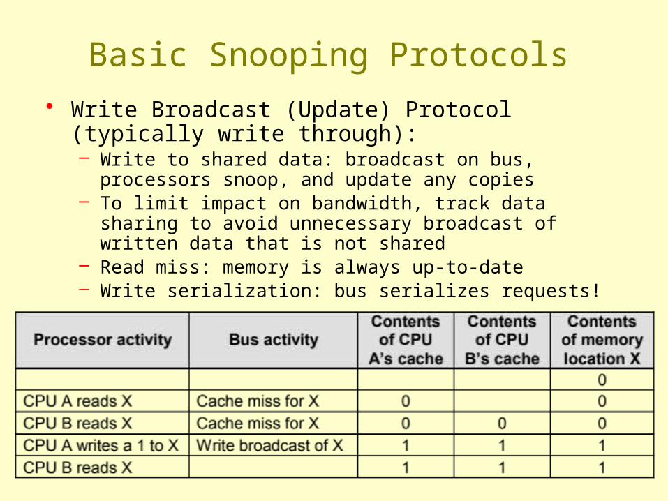
Basic Snooping Protocols• Write Broadcast (Update) Protocol (typically write
through):– Write to shared data: broadcast on bus, processors snoop,
and update any copies– To limit impact on bandwidth, track data sharing to avoid
unnecessary broadcast of written data that is not shared– Read miss: memory is always up-to-date– Write serialization: bus serializes requests!

Invalidate vs. Update
• Write-invalidate has emerged as the winner for the vast majority of designs
• Qualitative Performance Differences :– Spatial locality
• WI: 1 transaction/cache block; • WU: 1 broadcast/word
– Latency• WU: lower write–read latency• WI: must reload new value to cache
Invalidate vs. Update
• Because the bus and memory bandwidth is usually in demand, write-invalidate protocols are very popular
• Write-update can causes problems for some memory consistency models, reducing the potential performance gain it could bring
• The high demand for bandwidth in write-update limits its scalability for large number of processors

An Example Snoopy Protocol
• Invalidation protocol, write-back cache• Each block of memory is in one state:
– Clean in all caches and up-to-date in memory (Shared)
– OR Dirty in exactly one cache (Exclusive)– OR Not in any caches
• Each cache block is in one state (track these):– Shared : block can be read– OR Exclusive : cache has only copy, it is write-able,
and dirty– OR Invalid : block contains no data
• Read misses: cause all caches to snoop bus• Writes to clean line are treated as misses

Snoopy-Cache Controller• Complications
– Cannot update cache until bus is obtained
– Two step process:• Arbitrate for bus • Place miss on bus and
complete operation– Split transaction bus:
• Bus transaction is not atomic
• Multiple misses can interleave, allowing two caches to grab block in the Exclusive state
• Must track and prevent multiple misses for one block

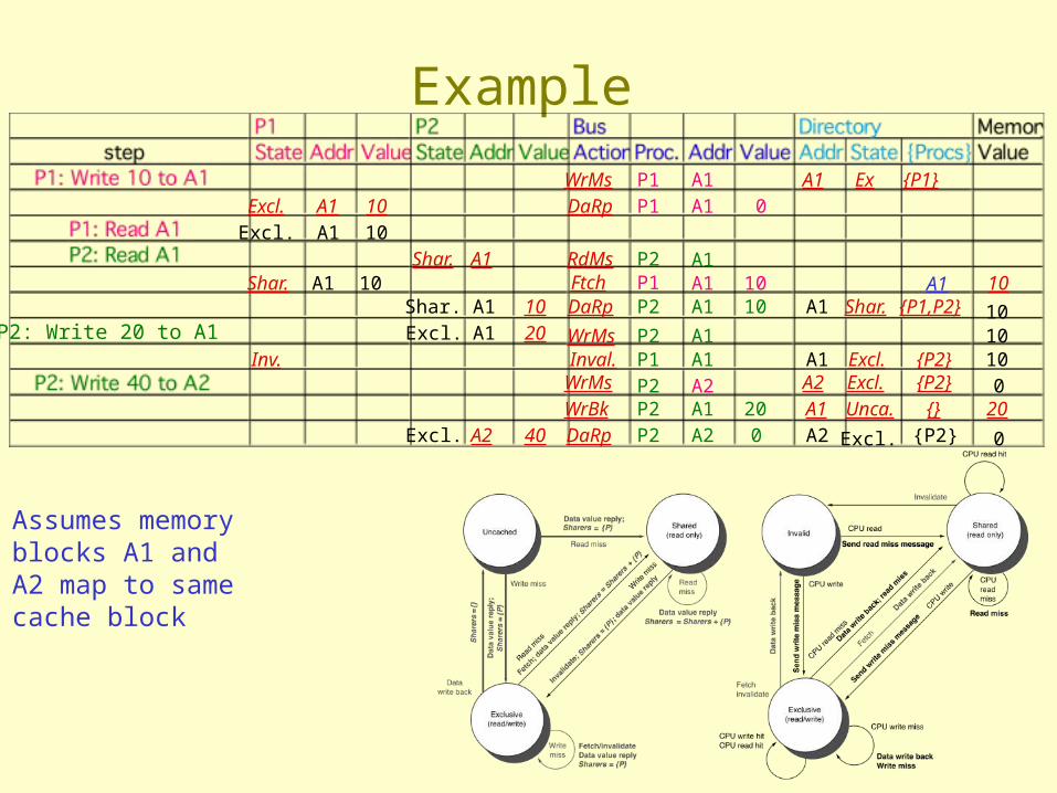
Assumes memory blocks A1 and A2 map to same cache block, initial cache state is invalid
Example

Assumes memory blocks A1 and A2 map to same cache block
Example

Assumes memory blocks A1 and A2 map to same cache block
Example

Example
Assumes memory blocks A1 and A2 map to same cache block

Example
Assumes memory blocks A1 and A2 map to same cache block

Example
A1
A1
Assumes memory blocks A1 and A2 map to same cache block

Distributed Directory Multiprocessors
• Directory per cache that tracks state of every block in every cache– Which caches have a block, dirty vs. clean, ...– Info per memory block vs. per cache block?
+ In memory => simpler protocol (centralized/one location)– In memory => directory is f(memory size) vs. f(cache size)
• To prevent directory from being a bottleneck– distribute directory entries with memory– each tracks of
which processor has their blocks
Directory Protocol
• Similar to Snoopy Protocol: Three states– Shared: Multiple processors have the block cached
and the contents of the block in memory (as well as all caches) is up-to-date
– Uncached No processor has a copy of the block (not valid in any cache)
– Exclusive: Only one processor (owner) has the block cached and the contents of the block in memory is out-to-date (the block is dirty)
• In addition to cache state, must track which processors have data when in the shared state – usually bit vector, 1 if processor has copy

Directory Protocol
• Keep it simple(r):– Writes to non-exclusive data => write miss– Processor blocks until access completes– Assume messages received and acted upon in
order sent• Terms: typically 3 processors involved
– Local node where a request originates– Home node where the memory location of an
address resides– Remote node has a copy of a cache block, whether
exclusive or shared• No bus and do not want to broadcast:
– interconnect no longer single arbitration point– all messages have explicit responses

Example Directory Protocol
• Message sent to directory causes two actions:– Update the directory– More messages to satisfy request
• We assume operations atomic, but they are not; reality is much harder; must avoid deadlock when run out of buffers in network
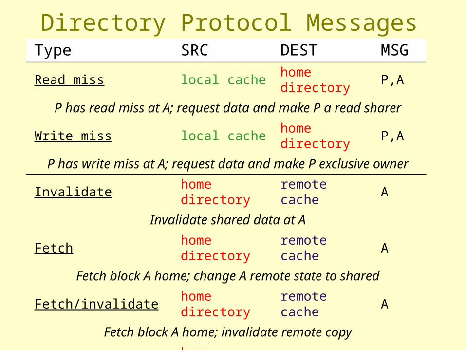
Type SRC DEST MSGRead miss local cache home directory P,A
P has read miss at A; request data and make P a read sharer
Write miss local cache home directory P,A
P has write miss at A; request data and make P exclusive owner
Invalidate home directory remote cache A
Invalidate shared data at A
Fetch home directory remote cache A
Fetch block A home; change A remote state to shared
Fetch/invalidate home directory remote cache A
Fetch block A home; invalidate remote copy
Data value reply home directory local cache D
Return data value from home memory
Data write back remote cache home directory A,D
Write back data value for A
Directory Protocol Messages

State machine for CPU requests for each memory block
Cache Controller State Machine
• States identical to snoopy case– Transactions very
similar.• Miss messages to
home directory• Explicit invalidate &
data fetch requests
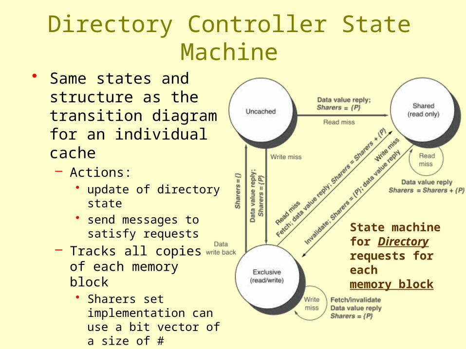
State machinefor Directory requests for each memory block
Directory Controller State Machine
• Same states and structure as the transition diagram for an individual cache– Actions:
• update of directory state • send messages to satisfy
requests – Tracks all copies of each
memory block • Sharers set
implementation can use a bit vector of a size of # processors for each block
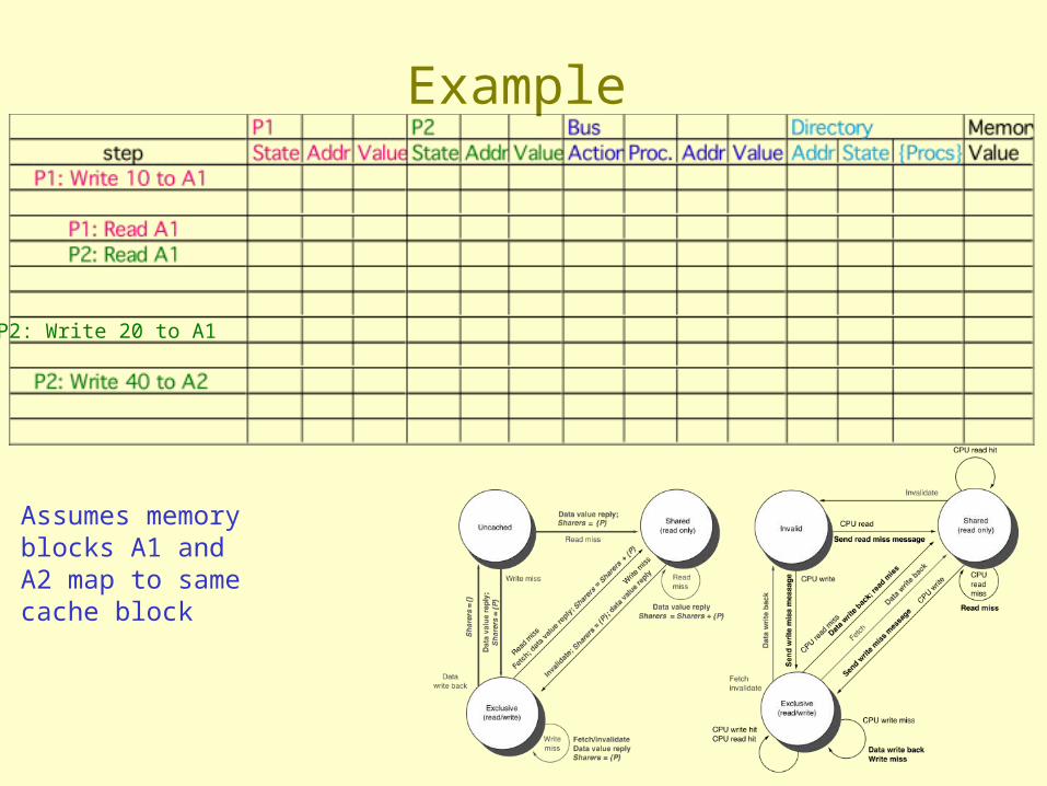
Example
P2: Write 20 to A1
Assumes memory blocks A1 and A2 map to same cache block
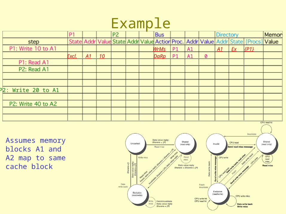
P2: Write 20 to A1
WrMs P1 A1 A1 Ex {P1}Excl. A1 10 DaRp P1 A1 0
Assumes memory blocks A1 and A2 map to same cache block
Example

P2: Write 20 to A1
WrMs P1 A1 A1 Ex {P1}Excl. A1 10 DaRp P1 A1 0Excl. A1 10
Assumes memory blocks A1 and A2 map to same cache block
Example

P2: Write 20 to A1
WrMs P1 A1 A1 Ex {P1}Excl. A1 10 DaRp P1 A1 0Excl. A1 10
Shar. A1 RdMs P2 A1Shar. A1 10 Ftch P1 A1 10 10
Shar. A1 10 DaRp P2 A1 10 A1 Shar. {P1,P2} 10
A1
Write Back
Assumes memory blocks A1 and A2 map to same cache block
Example

Example
P2: Write 20 to A1
Excl. A1 10 DaRp P1 A1 0Excl. A1 10
Shar. A1 RdMs P2 A1Shar. A1 10 Ftch P1 A1 10 10
Shar. A1 10 DaRp P2 A1 10 A1 Shar. {P1,P2} 10
A1
Excl. A1 20 WrMs P2 A1 10Inv. Inval. P1 A1 A1 Excl. {P2} 10
Assumes memory blocks A1 and A2 map to same cache block
Example
P2: Write 20 to A1
WrMs P1 A1 A1 Ex {P1}Excl. A1 10 DaRp P1 A1 0Excl. A1 10
Shar. A1 RdMs P2 A1Shar. A1 10 Ftch P1 A1 10 10
Shar. A1 10 DaRp P2 A1 10 A1 Shar. {P1,P2} 10
A1
Excl. A1 20 WrMs P2 A1 10Inv. Inval. P1 A1 A1 Excl. {P2} 10
WrBk P2 A1 20 A1 Unca. {} 20Excl. A2 40 DaRp P2 A2 0 A2 Excl. {P2} 0
WrMs P2 A2 A2 Excl. {P2} 0
Assumes memory blocks A1 and A2 map to same cache block

Interconnection Networks
• Local area network (LAN)– Hundreds of computers– A few kilometers– Many-to-one (clients-server)
• Wide area network (WAN)– Thousands of computers– Thousands of kilometers
• Massively processor networks (MPP)– Thousands of nodes– Short distance (<~25m)– Traffic among nodes

ABCs of Networks
• Rules for communication are called the “protocol”, message header and data called a "packet"– What if more than 2 computers want to communicate?
• Need computer “address field” (destination) in packet– What if packet is garbled in transit?
• Add “error detection field” in packet (e.g., CRC)– What if packet is lost?
• Time-out, retransmit; ACK & NACK– What if multiple processes/machine?
• Queue per process to provide protection

Sender
Receiver
SenderOverhead
Transmission time(size ÷ bandwidth)
Transmission time(size ÷ bandwidth)
Time ofFlight
ReceiverOverhead
Transport Latency
Total Latency
(processorbusy)
(processorbusy)
Performance Metrics
• Bandwidth: maximum rate of propagating information• Time of flight: time for 1st bit to reach destination• Overhead: software & hardware time for encoding/decoding,
interrupt handling, etc.
Time ofFlight
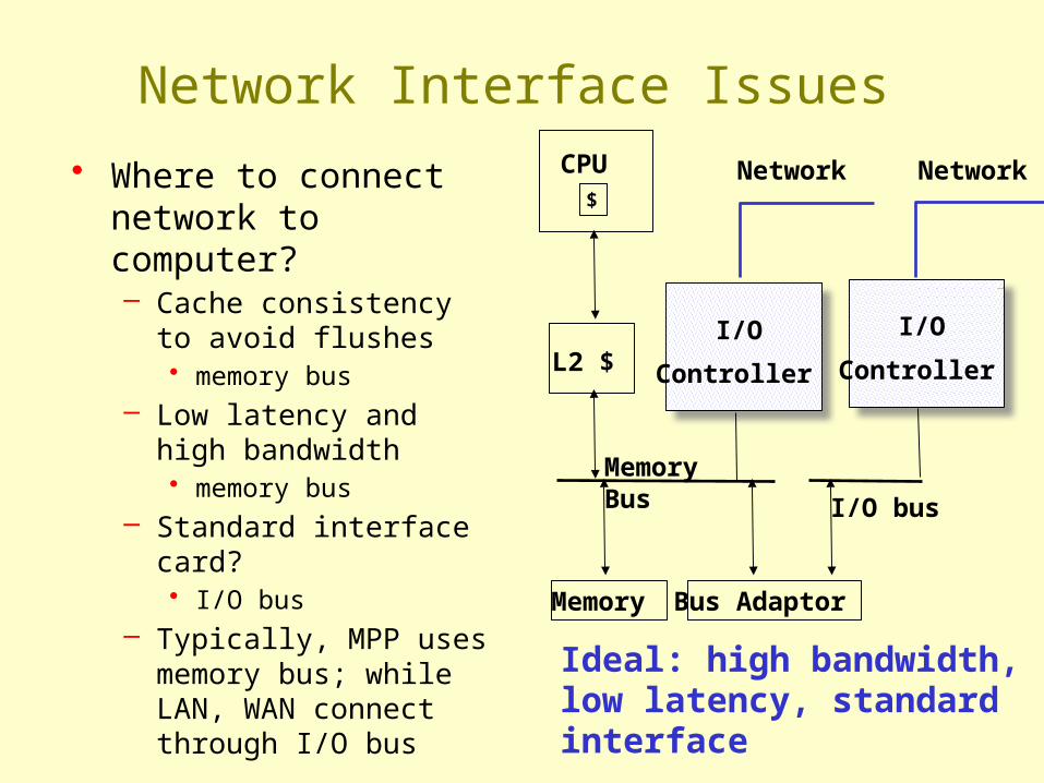
Ideal: high bandwidth, low latency, standard interface
$
CPU
L2 $
Memory Bus
Memory Bus Adaptor
I/O bus
I/O
Controller
I/O
Controller
NetworkNetwork
Network Interface Issues
• Where to connect network to computer?– Cache consistency to
avoid flushes • memory bus
– Low latency and high bandwidth • memory bus
– Standard interface card?• I/O bus
– Typically, MPP uses memory bus; while LAN, WAN connect through I/O bus