CMP Products
184
CMP Industrial and Hazardous Area Cable Glands and Accessories Single Solution Three Forms of Protection Ex d / Ex e / Ex nR CMP PRODUCTS SEPTEMBER 2007 Incorporating Triple Certified Products
-
Upload
olabimpe-olaosebikan-tejumola -
Category
Documents
-
view
417 -
download
0
Transcript of CMP Products

CMP
Industrial and Hazardous Area Cable Glands and Accessories
Single SolutionThree Forms of ProtectionEx d / Ex e / Ex nR
CMP PRODUCTS
SEPTEMBER 2007
Incorporating TripleCertified Products

CMP Products is a division of British Engines Limited, acompany registered in England, number 167542.
British Engines Limited (BEL) was founded in St. Peters,Newcastle upon Tyne in 1922, when two brothers fromGlasgow, Harold and Charles Lamb established theCompany. Today the Company proudly remains in thesame family ownership with Mr. Alex Lamb its presentchairman, the grandson of one of the founders.
The early British Engines Limited business wasconducted from a building suitable for housing less than12 employees, with marine engineering and sub-contractmachining work being at the core of its activities. TheCompany had entered the marine engineering marketwhen it began servicing, overhauling and reconditioningdiesel engines for marine vessels. The Company'sdevelopment relied largely upon the success of itscustomers, as it did not originally offer any of its ownproducts, and its business was increasingly subject tosporadic fluctuation. Having identified that it was not incontrol of its own destiny, the Company consequentlydecided to employ a product development strategy, andembark on a path of diversification and significantbusiness growth.
In 1957, cable terminating glands were introduced byBritish Engines Limited, that were marketed under theCMP brand. These have been continuously developedto meet increasingly difficult industry conditions, and tostay in pace with ever changing international technicalstandards. The CMP Products division remains a worldleader in the field of cable connecting for industrial andhazardous area installations, designing, manufacturing,and distributing cable glands, adaptors, reducers,stopper plugs, breathers, drain plugs, and accessories,with a wide array of global third party certification.
Other business units of British Engines Limited werelater created, including in 1962 the division known todayas BEL Valves. This division designs, manufactures andsupplies specialised high-pressure valves andassociated actuator sets for the oil, gas and petro-chemical industries. BEL Valves has evolved into aworld renowned provider of bespoke valve solutions tocustomer specification, which are used in the onshoreand offshore industries, including the more specialisedsub-sea arena.
A comprehensive range of industrial hydraulic pumpsand motors was developed by what is now known as theRotary Power division which services a variety ofInternational markets, with customers engaged in thepolyethylene pumping, mining, drilling, trenching, andagricultural machinery business. Stephenson GobinEngineering, is a British Engines Limited division whichdesigns, manufactures and supplies a range ofelectromagnetic door retainers and a variety of othercontrol mechanisms, including electromagnetic clutchesand brakes used in the automation industries. The BELGroup also includes a packaging division, StadiumPacking Services, which manufactures standard andcustomised packing cases, complying with therequirements for deep sea, road and air export cargo,and the exacting Ministry of Defence standards.
British Engines Limited currently occupies an area of600,000 square feet, and employs in excess of 1000people, the majority of which are located on the nowgreatly expanded St. Peters site. Company offices canalso be found overseas in places such as U.S.A.,U.A.E., Germany, Singapore, China, South Korea andAustralia.
To ensure the company maintains its market leadingposition, people development is at the forefront of itsactivities, ensuring that individuals maximise their ownpotential and career aspirations in tandem with theCompany's business requirements. In conjunction withits positive Human Resource Policies, the Company hasmaintained its "Investors in People" accolade on aconsistent basis.
With the dedication of experienced personnel, continualinvestment in plant and machinery, allowing the Groupto develop and market quality products at competitiveprices, CMP Products is able to look forward tocontinued managed growth in the future years.
BRIEF HISTORY OF BRITISH ENGINES LIMITED
1

2
INDEX
3 www.cmp-products.com
CMP C A B L E G L A N D A N D C A B L E C O N N E C T I O N S P E C I A L I S T S
INDEX
BRIEF COMPANY HISTORY
VISION STATEMENT
TECHNICAL CONTENTS LOCATOR
MATRIX OF INDUSTRIAL PRODUCTS
MATRIX OF HAZARDOUS AREA PRODUCTS
TECHNICAL & APPLICATION INFORMATION BASE
INDUSTRIAL CABLE GLAND PRODUCTS
1
2
5-6
7-8
9-10
11-74
75-94
CMP SOLO - LOW SMOKE & FUME RANGE - HALOGEN FREE PRODUCTS 95-98
CMP CIEL - CAST INTEGRAL EARTH LUG EQUIPPED PRODUCTS 99-104
INDEX
4www.cmp-products.com
C A B L E G L A N D A N D C A B L E C O N N E C T I O N S P E C I A L I S T S CMP
INDEX
ZEN INSULATED PRODUCTS FOR SAFE EARTHING SYSTEMS
HAZARDOUS AREA CABLE GLAND PRODUCTS (ATEX & IEC Ex)
MINING PRODUCTS FOR SURFACE & UNDERGROUND APPLICATIONS
NORTH AMERICAN SPECIFICATION CABLE CONNECTOR PRODUCTS
THREAD CONVERSION ADAPTORS AND REDUCERS
105-110
111-134
135-148
149-158
159-172
ACCESSORIES
TYPICAL INSTALLATION CONFIGURATIONS
MATERIAL AND THREAD SPECIFICATIONS
CABLE GLAND SELECTOR CHARTS
173-175
176
177
178-182
MATRIXOF
INDUSTRIAL
PRODUCTS
5 www.cmp-products.com
CMP C A B L E G L A N D A N D C A B L E C O N N E C T I O N S P E C I A L I S T S
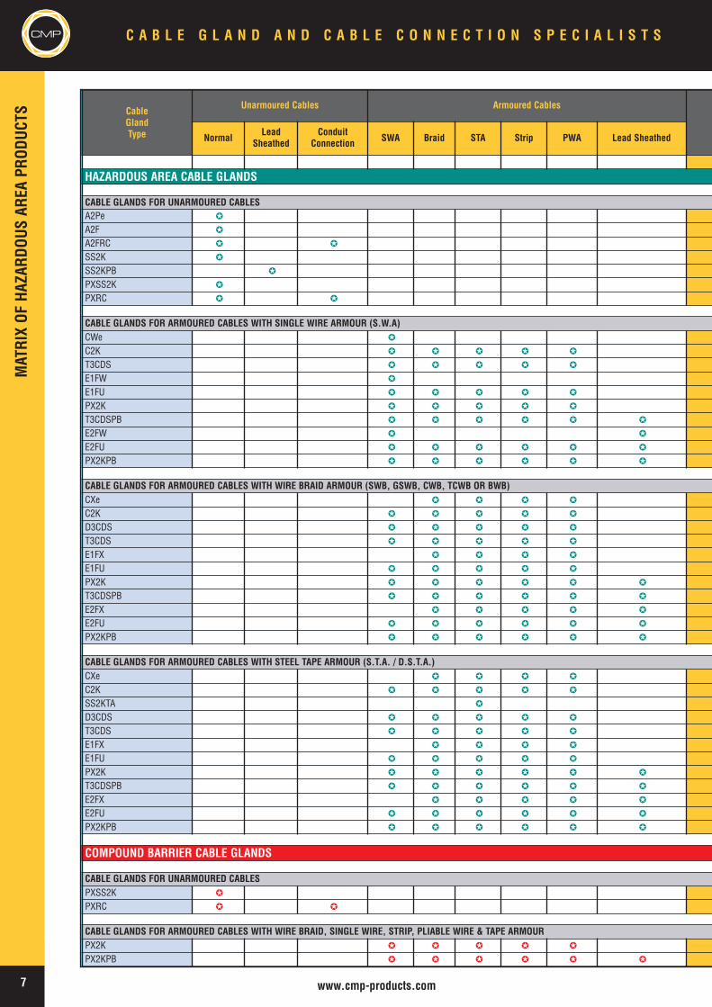
CableGlandType
Unarmoured Cables Armoured Cables
NormalLead
SheathedConduit
Connection SWA Braid STA Strip PWA Lead Sheathed
INDUSTRIAL CABLE GLANDS
CABLE GLANDS FOR UNARMOURED CABLESA2 �
A2RC � �
SS2KGP �
SS2KGP PB �
A2DG �
A2 200 �
CABLE GLANDS FOR ARMOURED CABLES WITH SINGLE WIRE (S.W.A)BW �
BWL �
CW �
C2KGP � � � � �
E1W �
E1U � � � � �
E2W � �
E2U � � � � � �
CABLE GLANDS FOR ARMOURED CABLES WITH ALUMINIUM SINGLE WIRE (A.W.A)CW ALUMINIUM �
E1W ALUMINIUM �
E1U ALUMINIUM � � � � �
E2W ALUMINIUM � �
E2U ALUMINIUM � � � � � �
CABLE GLANDS FOR ARMOURED CABLES WITH WIRE BRAID ARMOUR (SWB, GSWB, CWB, TCWB OR BWB) OR SCREENED (BRAIDED) FLEXIBLECX � � � �
C2K GP � � � � �
CXT �
E1X � � � �
E1U � � � � �
E2X � � � � �
E2U � � � � � �
CABLE GLANDS FOR ARMOURED CABLES WITH STEEL TAPE ARMOUR (S.T.A. / D.S.T.A.)CX � � � �
C2K GP � � � � �
SS2KGP PB � �
E1X � � � �
E1U � � � � �
E2X � � � � �
E2U � � � � � �
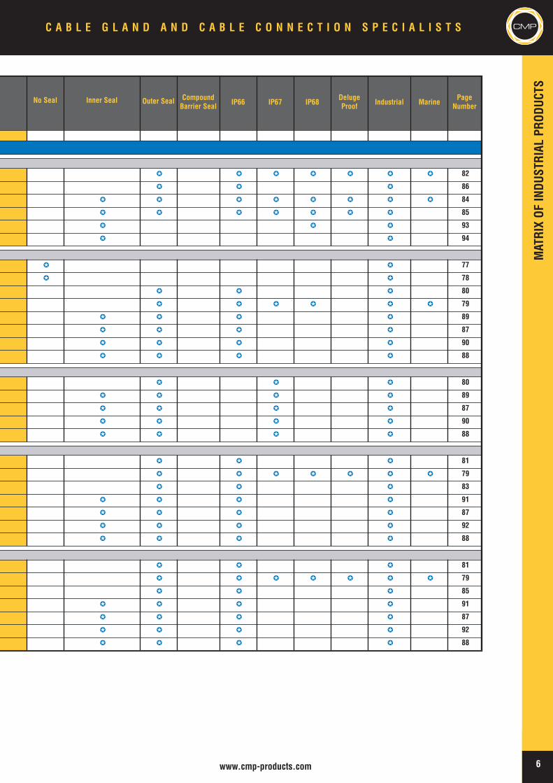
MATRIXOF
INDUSTRIAL
PRODUCTS
6www.cmp-products.com
CMPC A B L E G L A N D A N D C A B L E C O N N E C T I O N S P E C I A L I S T S
No Seal Inner Seal Outer Seal CompoundBarrier Seal IP66 IP67 IP68
DelugeProof Industrial Marine
PageNumber
� � � � � � � 82
� � � 86
� � � � � � � � 84
� � � � � � � 85
� � � 93
� � 94
� � 77
� � 78
� � � 80
� � � � � � 79
� � � � 89
� � � � 87
� � � � 90
� � � � 88
� � � 80
� � � � 89
� � � � 87
� � � � 90
� � � � 88
� � � 81
� � � � � � � 79
� � � 83
� � � � 91
� � � � 87
� � � � 92
� � � � 88
� � � 81
� � � � � � � 79
� � � 85
� � � � 91
� � � � 87
� � � � 92
� � � � 88
7 www.cmp-products.com
CMP C A B L E G L A N D A N D C A B L E C O N N E C T I O N S P E C I A L I S T S
CableGlandType
Unarmoured Cables Armoured Cables
NormalLead
SheathedConduit
Connection SWA Braid STA Strip PWA Lead Sheathed
HAZARDOUS AREA CABLE GLANDS
CABLE GLANDS FOR UNARMOURED CABLESA2Pe �
A2F �
A2FRC � �
SS2K �
SS2KPB �
PXSS2K �
PXRC � �
CABLE GLANDS FOR ARMOURED CABLES WITH SINGLE WIRE ARMOUR (S.W.A)CWe �
C2K � � � � �
T3CDS � � � � �
E1FW �
E1FU � � � � �
PX2K � � � � �
T3CDSPB � � � � � �
E2FW � �
E2FU � � � � � �
PX2KPB � � � � � �
CABLE GLANDS FOR ARMOURED CABLES WITH WIRE BRAID ARMOUR (SWB, GSWB, CWB, TCWB OR BWB)CXe � � � �
C2K � � � � �
D3CDS � � � � �
T3CDS � � � � �
E1FX � � � �
E1FU � � � � �
PX2K � � � � � �
T3CDSPB � � � � � �
E2FX � � � � �
E2FU � � � � � �
PX2KPB � � � � � �
CABLE GLANDS FOR ARMOURED CABLES WITH STEEL TAPE ARMOUR (S.T.A. / D.S.T.A.)CXe � � � �
C2K � � � � �
SS2KTA �
D3CDS � � � � �
T3CDS � � � � �
E1FX � � � �
E1FU � � � � �
PX2K � � � � � �
T3CDSPB � � � � � �
E2FX � � � � �
E2FU � � � � � �
PX2KPB � � � � � �
COMPOUND BARRIER CABLE GLANDS
CABLE GLANDS FOR UNARMOURED CABLESPXSS2K �
PXRC � �
CABLE GLANDS FOR ARMOURED CABLES WITH WIRE BRAID, SINGLE WIRE, STRIP, PLIABLE WIRE & TAPE ARMOURPX2K � � � � �
PX2KPB � � � � � �
MATRIXOF
HAZARDOUSAREA
PRODUCTS
MATRIXOF
HAZARDOUSAREA
PRODUCTS
8www.cmp-products.com
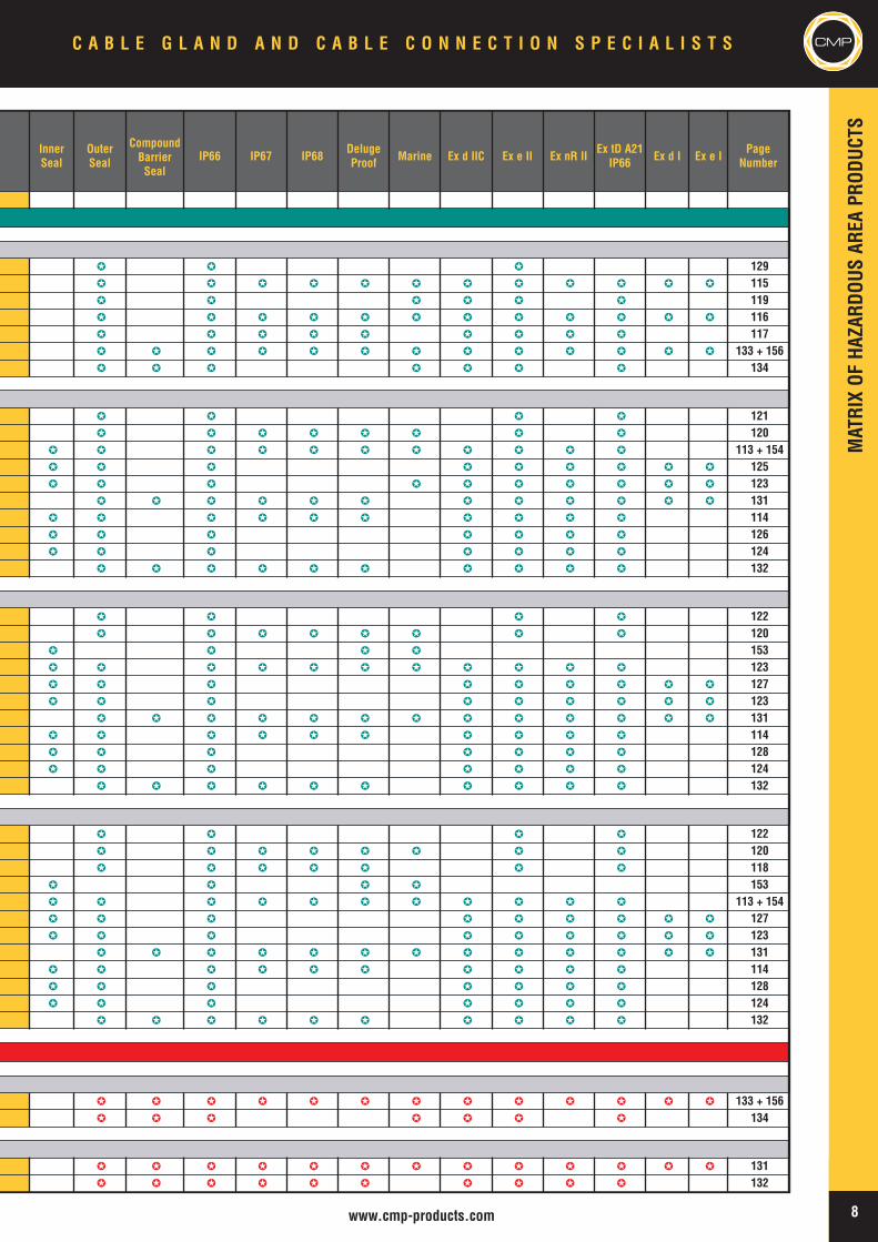
CMPC A B L E G L A N D A N D C A B L E C O N N E C T I O N S P E C I A L I S T S
InnerSeal
OuterSeal
CompoundBarrierSeal
IP66 IP67 IP68DelugeProof Marine Ex d IIC Ex e II Ex nR II
Ex tD A21IP66 Ex d I Ex e I
PageNumber
� � � 129� � � � � � � � � � � � 115� � � � � � 119� � � � � � � � � � � � 116� � � � � � � � � 117� � � � � � � � � � � � � 133 + 156� � � � � � � 134
� � � � 121� � � � � � � � 120
� � � � � � � � � � � 113 + 154� � � � � � � � � 125� � � � � � � � � � 123
� � � � � � � � � � � � 131� � � � � � � � � � 114� � � � � � � 126� � � � � � � 124
� � � � � � � � � � 132
� � � � 122� � � � � � � � 120
� � � � 153� � � � � � � � � � � 123� � � � � � � � � 127� � � � � � � � � 123
� � � � � � � � � � � � � 131� � � � � � � � � � 114� � � � � � � 128� � � � � � � 124
� � � � � � � � � � 132
� � � � 122� � � � � � � � 120� � � � � � � 118
� � � � 153� � � � � � � � � � � 113 + 154� � � � � � � � � 127� � � � � � � � � 123
� � � � � � � � � � � � � 131� � � � � � � � � � 114� � � � � � � 128� � � � � � � 124
� � � � � � � � � � 132
� � � � � � � � � � � � � 133 + 156� � � � � � � 134
� � � � � � � � � � � � � 131� � � � � � � � � � 132
TECHNICALCONTENTS
LOCATOR
9 www.cmp-products.com
CMP C A B L E G L A N D A N D C A B L E C O N N E C T I O N S P E C I A L I S T S
6
TECHNICAL CONTENTS LOCATOR
Introduction to Cable Glands ......................................................................................................................11Construction & Performance Standards ...........................................................................................11-14Crucial Cable Care ................................................................................................................................... 15-16Overview of Cable Gland Construction Types ................................................................................. 16-17Industry Standard Cable Gland Designations ................................................................................. 17-18
Generic Cable References ..................................................................................................................... 18-19Fire Performance Cables ............................................................................................................................. 20Halogen Free or Low Smoke & Fume Materials ................................................................................... 20CMP SOLO Low Smoke & Fume (LSF) Materials ................................................................................ 21Getting to Grips with Soft Bedded Cables .............................................................................................. 22
Ingress Protection Ratings ................................................................................................................... 22-23Deluge Protection Specification .......................................................................................................... 24-25Health & Safety at Work .............................................................................................................................. 25Functional Safety ............................................................................................................................................25Electrical Safety in the Work Place ........................................................................................................... 26Wiring Regulations and Earthing Requirements ............................................................................ 26-27Safe Earthing Systems ...........................................................................................................................27-28
CE Marking ...................................................................................................................................................... 29Low Voltage Directive ................................................................................................................................... 29EMC Directive .......................................................................................................................................... 29-30RoHS & WEEE Directives ............................................................................................................................ 31Quality Management ..................................................................................................................................... 31Health, Safety & Environment ................................................................................................................... 31
Cable Gland Selection Guidelines ............................................................................................................. 32How to Order .................................................................................................................................................. 33
Introduction to Hazardous Areas (according to IEC) .......................................................................... 34Explosion Hazards ........................................................................................................................................ 34Principles of Protection ............................................................................................................................... 34Risk Assessment Process for Hazardous Areas ................................................................................... 35Sources of Release ....................................................................................................................................... 35Grades of Release ......................................................................................................................................... 35Flammable Material Properties ........................................................................................................... 35-36
TECHNICALCONTENTS
LOCATOR
10www.cmp-products.com
CMPC A B L E G L A N D A N D C A B L E C O N N E C T I O N S P E C I A L I S T S CMP
TECHNICAL CONTENTS LOCATOR
Gas Groups ...................................................................................................................................................... 36Sources of Ignition ........................................................................................................................................ 36Hazardous Area Equipment ......................................................................................................................... 37Apparatus Surface Temperature Classification ...................................................................................... 37
Ambient Temperature .................................................................................................................................... 38Classification of Hazardous Areas ............................................................................................................. 38Zone Definitions ..............................................................................................................................................39Hazardous Area Forms of Protection ................................................................................................. 39-40Combustible Dust Hazards .................................................................................................................... 41-42ATEX Directives ........................................................................................................................................ 43-47
Non Electrical Equipment ............................................................................................................................ 47Compliance with IEC Standards and European Normatives .............................................................. 48Apparatus Marking ........................................................................................................................................ 49Purpose of Certification ............................................................................................................................... 50IEC Ex Certification Scheme ........................................................................................................................ 50Equipment Selection Process ..................................................................................................................... 51
Cable Glands for Hazardous Areas ..................................................................................................... 51-52Marking of Cable Glands for Hazardous Areas ............................................................................... 53-54Selection of Cables intended for use in Hazardous Areas .................................................................. 55Compatibility of Equipment, Cable and Cable Gland ............................................................................ 56Selection Process for Hazardous Area Cable Glands according to IEC ................................... 57-60
Cold Flow ................................................................................................................................................... 60-61Risk Assessment Factors affecting cable gland selection .................................................................. 61Installation ........................................................................................................................................................ 62Inspection & Maintenance ........................................................................................................................... 63Cable Glands for Mining Applications .......................................................................................................63
Hazardous Locations according to NEC ............................................................................................ 63-64Classification of Hazardous Locations, Class & Divisions ........................................................... 64-67Equipment for Use in Class & Division Hazardous Locations .................................................... 65-66Equipment for Use in Class & Zone Hazardous Locations .................................................................66Classification of Hazardous Locations, Class & Zones...................................................................66-67NEC Flammable Material (Gas / Vapor / Dust) Definitions ...........................................................66-67UL standards incorporating IEC Zoning principals.......................................................................... 68-69Comparison between IEC / NEC-CEC Applications ............................................................................... 69North American Installation & Wiring Code Rules ......................................................................... 69-70Overview of Cables Permitted in Hazardous Locations..................................................................71-74
TECHNICAL&APPLICATIONINFORM
ATIONBASE
11 www.cmp-products.com
CMP C A B L E G L A N D A N D C A B L E C O N N E C T I O N S P E C I A L I S T S
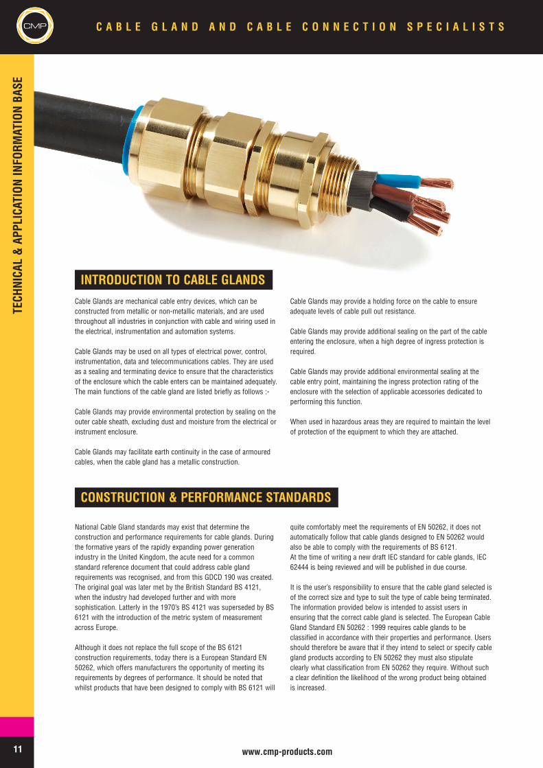
INTRODUCTION TO CABLE GLANDSCable Glands are mechanical cable entry devices, which can beconstructed from metallic or non-metallic materials, and are usedthroughout all industries in conjunction with cable and wiring used inthe electrical, instrumentation and automation systems.
Cable Glands may be used on all types of electrical power, control,instrumentation, data and telecommunications cables. They are usedas a sealing and terminating device to ensure that the characteristicsof the enclosure which the cable enters can be maintained adequately.The main functions of the cable gland are listed briefly as follows :-
Cable Glands may provide environmental protection by sealing on theouter cable sheath, excluding dust and moisture from the electrical orinstrument enclosure.
Cable Glands may facilitate earth continuity in the case of armouredcables, when the cable gland has a metallic construction.
Cable Glands may provide a holding force on the cable to ensureadequate levels of cable pull out resistance.
Cable Glands may provide additional sealing on the part of the cableentering the enclosure, when a high degree of ingress protection isrequired.
Cable Glands may provide additional environmental sealing at thecable entry point, maintaining the ingress protection rating of theenclosure with the selection of applicable accessories dedicated toperforming this function.
When used in hazardous areas they are required to maintain the levelof protection of the equipment to which they are attached.
CONSTRUCTION & PERFORMANCE STANDARDS
National Cable Gland standards may exist that determine theconstruction and performance requirements for cable glands. Duringthe formative years of the rapidly expanding power generationindustry in the United Kingdom, the acute need for a commonstandard reference document that could address cable glandrequirements was recognised, and from this GDCD 190 was created.The original goal was later met by the British Standard BS 4121,when the industry had developed further and with moresophistication. Latterly in the 1970’s BS 4121 was superseded by BS6121 with the introduction of the metric system of measurementacross Europe.
Although it does not replace the full scope of the BS 6121construction requirements, today there is a European Standard EN50262, which offers manufacturers the opportunity of meeting itsrequirements by degrees of performance. It should be noted thatwhilst products that have been designed to comply with BS 6121 will
quite comfortably meet the requirements of EN 50262, it does notautomatically follow that cable glands designed to EN 50262 wouldalso be able to comply with the requirements of BS 6121.At the time of writing a new draft IEC standard for cable glands, IEC62444 is being reviewed and will be published in due course.
It is the user’s responsibility to ensure that the cable gland selected isof the correct size and type to suit the type of cable being terminated.The information provided below is intended to assist users inensuring that the correct cable gland is selected. The European CableGland Standard EN 50262 : 1999 requires cable glands to beclassified in accordance with their properties and performance. Usersshould therefore be aware that if they intend to select or specify cablegland products according to EN 50262 they must also stipulateclearly what classification from EN 50262 they require. Without sucha clear definition the likelihood of the wrong product being obtainedis increased.
12www.cmp-products.com
CMPC A B L E G L A N D A N D C A B L E C O N N E C T I O N S P E C I A L I S T S
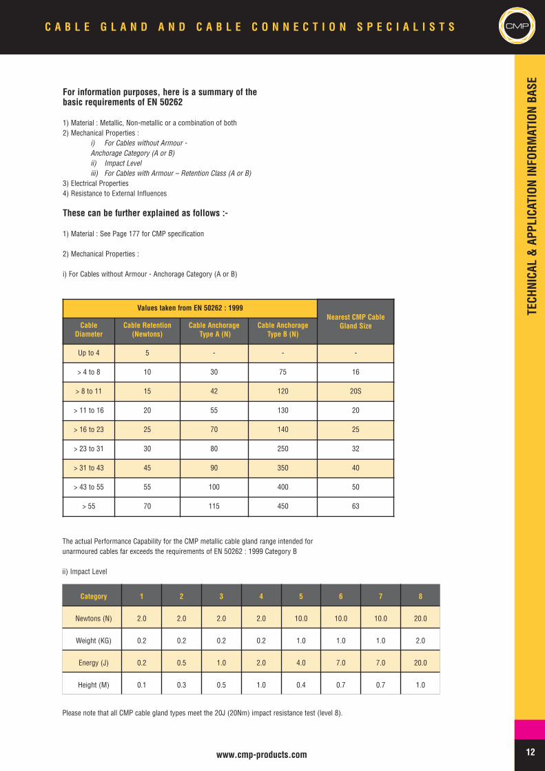
Values taken from EN 50262 : 1999Nearest CMP Cable
Gland SizeCableDiameter
Cable Retention(Newtons)
Cable AnchorageType A (N)
Cable AnchorageType B (N)
Up to 4 5 - - -
> 4 to 8 10 30 75 16
> 8 to 11 15 42 120 20S
> 11 to 16 20 55 130 20
> 16 to 23 25 70 140 25
> 23 to 31 30 80 250 32
> 31 to 43 45 90 350 40
> 43 to 55 55 100 400 50
> 55 70 115 450 63
The actual Performance Capability for the CMP metallic cable gland range intended forunarmoured cables far exceeds the requirements of EN 50262 : 1999 Category B
ii) Impact Level
Please note that all CMP cable gland types meet the 20J (20Nm) impact resistance test (level 8).
Category 1 2 3 4 5 6 7 8
Newtons (N) 2.0 2.0 2.0 2.0 10.0 10.0 10.0 20.0
Weight (KG) 0.2 0.2 0.2 0.2 1.0 1.0 1.0 2.0
Energy (J) 0.2 0.5 1.0 2.0 4.0 7.0 7.0 20.0
Height (M) 0.1 0.3 0.5 1.0 0.4 0.7 0.7 1.0
For information purposes, here is a summary of thebasic requirements of EN 50262
1) Material : Metallic, Non-metallic or a combination of both2) Mechanical Properties :
i) For Cables without Armour -Anchorage Category (A or B)ii) Impact Leveliii) For Cables with Armour – Retention Class (A or B)
3) Electrical Properties4) Resistance to External Influences
These can be further explained as follows :-
1) Material : See Page 177 for CMP specification
2) Mechanical Properties :
i) For Cables without Armour - Anchorage Category (A or B)
TECHNICAL&APPLICATIONINFORM
ATIONBASE
13 www.cmp-products.com
CMP C A B L E G L A N D A N D C A B L E C O N N E C T I O N S P E C I A L I S T S
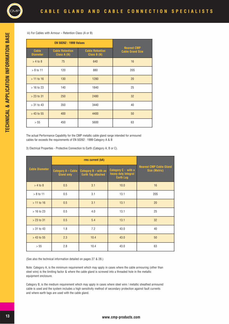
The actual Performance Capability for the CMP metallic cable gland range intended for armouredcables far exceeds the requirements of EN 50262 : 1999 Category A & B
3) Electrical Properties - Protective Connection to Earth (Category A, B or C).
EN 50262 : 1999 Values
Nearest CMP Cable Grand SizeCable
DiameterCable Retention
Class A (N)Cable Retention
Class B (N)
> 4 to 8 75 640 16
> 8 to 11 120 880 20S
> 11 to 16 130 1280 20
> 16 to 23 140 1840 25
> 23 to 31 250 2480 32
> 31 to 43 350 3440 40
> 43 to 55 400 4400 50
> 55 450 5600 63
Cable Diameter
rms current (kA)
Nearest CMP Cable GlandSize (Metric)Category A – Cable
Gland onlyCategory B – with anEarth Tag attached
Category C - with aheavy duty Integral
Earth Lug
> 4 to 8 0.5 3.1 10.0 16
> 8 to 11 0.5 3.1 13.1 20S
> 11 to 16 0.5 3.1 13.1 20
> 16 to 23 0.5 4.0 13.1 25
> 23 to 31 0.5 5.4 13.1 32
> 31 to 43 1.8 7.2 43.0 40
> 43 to 55 2.3 10.4 43.0 50
> 55 2.8 10.4 43.0 63
(See also the technical information detailed on pages 27 & 28.)
Note: Category A, is the minimum requirement which may apply in cases where the cable armouring (other thansteel wire) is the limiting factor & where the cable gland is screwed into a threaded hole in the metallicequipment enclosure.
Category B, is the medium requirement which may apply in cases where steel wire / metallic sheathed armouredcable is used and the system includes a high sensitivity method of secondary protection against fault currentsand where earth tags are used with the cable gland.
iii) For Cables with Armour – Retention Class (A or B)
TECH
NICA
L &
APP
LICA
TION
INFO
RMAT
ION
BASE
14www.cmp-products.com
CMPC A B L E G L A N D A N D C A B L E C O N N E C T I O N S P E C I A L I S T S
5
CMP
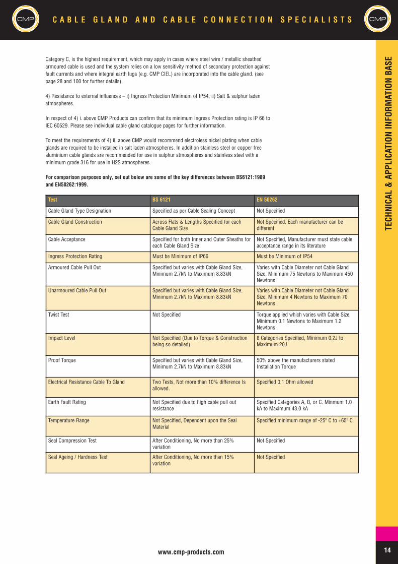
Category C, is the highest requirement, which may apply in cases where steel wire / metallic sheathedarmoured cable is used and the system relies on a low sensitivity method of secondary protection againstfault currents and where integral earth lugs (e.g. CMP CIEL) are incorporated into the cable gland. (seepage 28 and 100 for further details).
4) Resistance to external influences – i) Ingress Protection Minimum of IP54, ii) Salt & sulphur ladenatmospheres.
In respect of 4) i. above CMP Products can confirm that its minimum Ingress Protection rating is IP 66 toIEC 60529. Please see individual cable gland catalogue pages for further information.
To meet the requirements of 4) ii. above CMP would recommend electroless nickel plating when cableglands are required to be installed in salt laden atmospheres. In addition stainless steel or copper freealuminium cable glands are recommended for use in sulphur atmospheres and stainless steel with aminimum grade 316 for use in H2S atmospheres.
For comparison purposes only, set out below are some of the key differences between BS6121:1989and EN50262:1999.
Test BS 6121 EN 50262
Cable Gland Type Designation Specified as per Cable Sealing Concept Not Specified
Cable Gland Construction Across Flats & Lengths Specified for eachCable Gland Size
Not Specified, Each manufacturer can bedifferent
Cable Acceptance Specified for both Inner and Outer Sheaths foreach Cable Gland Size
Not Specified, Manufacturer must state cableacceptance range in its literature
Ingress Protection Rating Must be Minimum of IP66 Must be Minimum of IP54
Armoured Cable Pull Out Specified but varies with Cable Gland Size,Minimum 2.7kN to Maximum 8.83kN
Varies with Cable Diameter not Cable GlandSize, Minimum 75 Newtons to Maximum 450Newtons
Unarmoured Cable Pull Out Specified but varies with Cable Gland Size,Minimum 2.7kN to Maximum 8.83kN
Varies with Cable Diameter not Cable GlandSize, Minimum 4 Newtons to Maximum 70Newtons
Twist Test Not Specified Torque applied which varies with Cable Size,Minimum 0.1 Newtons to Maximum 1.2Newtons
Impact Level Not Specified (Due to Torque & Constructionbeing so detailed)
8 Categories Specified, Minimum 0.2J toMaximum 20J
Proof Torque Specified but varies with Cable Gland Size,Minimum 2.7kN to Maximum 8.83kN
50% above the manufacturers statedInstallation Torque
Electrical Resistance Cable To Gland Two Tests, Not more than 10% difference Isallowed.
Specified 0.1 Ohm allowed
Earth Fault Rating Not Specified due to high cable pull outresistance
Specified Categories A, B, or C. Minmum 1.0kA to Maximum 43.0 kA
Temperature Range Not Specified, Dependent upon the SealMaterial
Specified minimum range of -25º C to +65º C
Seal Compression Test After Conditioning, No more than 25%variation
Not Specified
Seal Ageing / Hardness Test After Conditioning, No more than 15%variation
Not Specified
TECHNICAL&APPLICATIONINFORM
ATIONBASE
15 www.cmp-products.com
CMP C A B L E G L A N D A N D C A B L E C O N N E C T I O N S P E C I A L I S T SCMP
CRUCIAL CABLE CARE
Overview of Different Seal Types
In general there are five different types of sealing methods used on thecable inner bedding, which are:-
i. Compression Sealii. Displacement Sealiii. Diaphragm Sealiv. Compensating Displacement Seal (CDS) Systemv. Compound Barrier Seal.
These are better described as follows :-
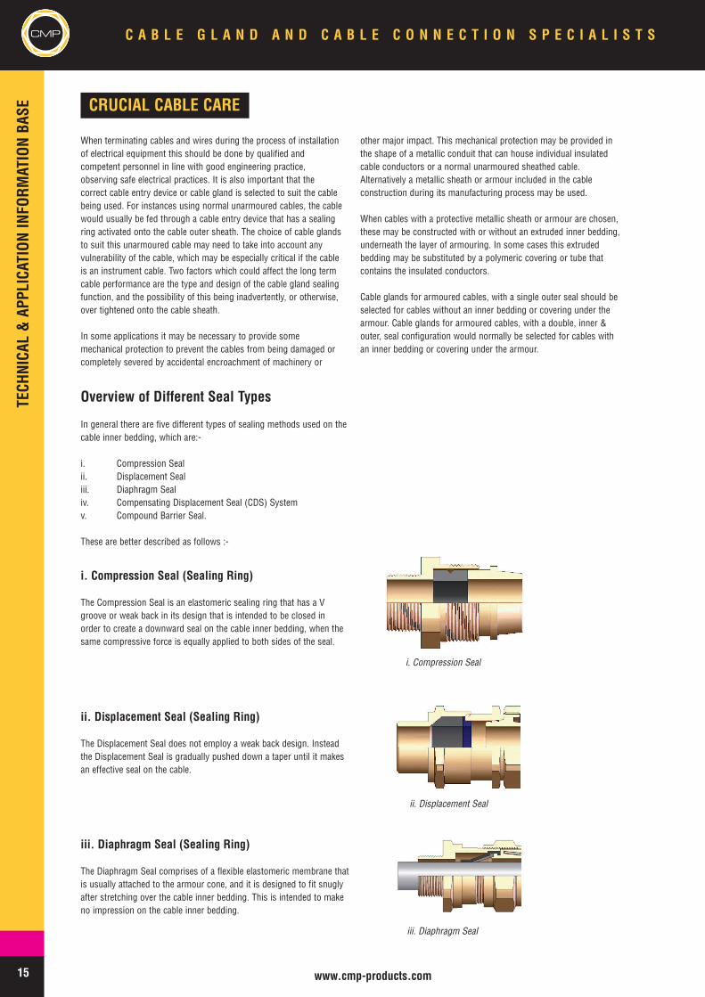
i. Compression Seal (Sealing Ring)
The Compression Seal is an elastomeric sealing ring that has a Vgroove or weak back in its design that is intended to be closed inorder to create a downward seal on the cable inner bedding, when thesame compressive force is equally applied to both sides of the seal.
ii. Displacement Seal (Sealing Ring)
The Displacement Seal does not employ a weak back design. Insteadthe Displacement Seal is gradually pushed down a taper until it makesan effective seal on the cable.
iii. Diaphragm Seal (Sealing Ring)
The Diaphragm Seal comprises of a flexible elastomeric membrane thatis usually attached to the armour cone, and it is designed to fit snuglyafter stretching over the cable inner bedding. This is intended to makeno impression on the cable inner bedding.
i. Compression Seal
ii. Displacement Seal
iii. Diaphragm Seal
When terminating cables and wires during the process of installationof electrical equipment this should be done by qualified andcompetent personnel in line with good engineering practice,observing safe electrical practices. It is also important that thecorrect cable entry device or cable gland is selected to suit the cablebeing used. For instances using normal unarmoured cables, the cablewould usually be fed through a cable entry device that has a sealingring activated onto the cable outer sheath. The choice of cable glandsto suit this unarmoured cable may need to take into account anyvulnerability of the cable, which may be especially critical if the cableis an instrument cable. Two factors which could affect the long termcable performance are the type and design of the cable gland sealingfunction, and the possibility of this being inadvertently, or otherwise,over tightened onto the cable sheath.
In some applications it may be necessary to provide somemechanical protection to prevent the cables from being damaged orcompletely severed by accidental encroachment of machinery or
other major impact. This mechanical protection may be provided inthe shape of a metallic conduit that can house individual insulatedcable conductors or a normal unarmoured sheathed cable.Alternatively a metallic sheath or armour included in the cableconstruction during its manufacturing process may be used.
When cables with a protective metallic sheath or armour are chosen,these may be constructed with or without an extruded inner bedding,underneath the layer of armouring. In some cases this extrudedbedding may be substituted by a polymeric covering or tube thatcontains the insulated conductors.
Cable glands for armoured cables, with a single outer seal should beselected for cables without an inner bedding or covering under thearmour. Cable glands for armoured cables, with a double, inner &outer, seal configuration would normally be selected for cables withan inner bedding or covering under the armour.
TECHNICAL&APPLICATIONINFORM
ATIONBASE
16www.cmp-products.com
CMPC A B L E G L A N D A N D C A B L E C O N N E C T I O N S P E C I A L I S T S
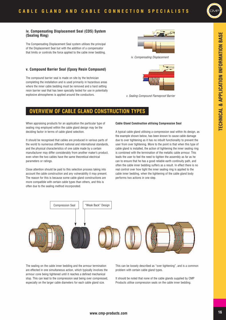
iv. Compensating Displacement Seal (CDS) System(Sealing Ring)
The Compensating Displacement Seal system utilises the principalof the Displacement Seal but with the addition of a compensatorthat limits or controls the force applied to the cable inner bedding.
v. Compound Barrier Seal (Epoxy Resin Compound)
The compound barrier seal is made on site by the techniciancompleting the installation and is used primarily in hazardous areaswhere the inner cable bedding must be removed and a hard settingresin barrier seal that has been specially tested for use in potentiallyexplosive atmospheres is applied around the conductors.
OVERVIEW OF CABLE GLAND CONSTRUCTION TYPES
When appraising products for an application the particular type ofsealing ring employed within the cable gland design may be thedeciding factor in terms of cable gland selection.
It should be recognised that cables are produced in various parts ofthe world to numerous different national and international standards,and the physical characteristics of one cable made by a certainmanufacturer may differ considerably from another maker’s product,even when the two cables have the same theoretical electricalparameters or ratings.
Close attention should be paid to this selection process taking intoaccount the cable construction and any vulnerability it may present.The reason for this is because some cable gland constructions aremore compatible with certain cable types than others, and this isoften due to the sealing method incorporated.
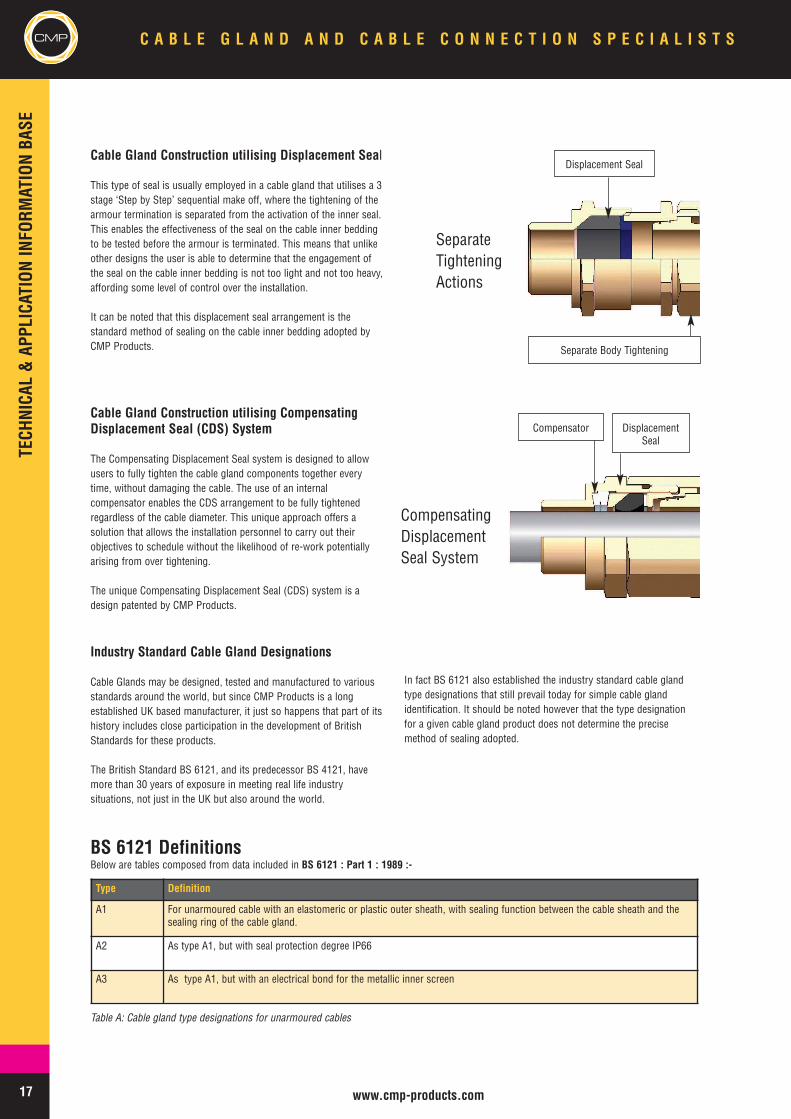
Cable Gland Construction utilising Compression Seal
A typical cable gland utilising a compression seal within its design, asthe example shown below, has been known to cause cable damagedue to over tightening as it has no inbuilt functionality to prevent theuser from over tightening. More to the point is that when this type ofcable gland is installed, the action of tightening the inner sealing ringis combined with the termination of the metallic cable armour. Thisleads the user to feel the need to tighten the assembly as far as hecan to ensure that he has a good reliable earth continuity path, andoften the cable inner bedding suffers as a result. In effect there is noreal control over how tight the inner sealing ring is applied to thecable inner bedding, when the tightening of the cable gland bodyperforms two actions in one step.
The sealing on the cable inner bedding and the armour terminationare effected in one simultaneous action, which typically involves thearmour cone being tightened until it reaches a defined mechanicalstop. This can lead to the compression seal being over compressed,especially on the larger cable diameters for each cable gland size.
This can be loosely described as “over tightening”, and is a commonproblem with certain cable gland types.
It should be noted that none of the cable glands supplied by CMPProducts utilise compression seals on the cable inner bedding.
iv. Compensating Displacement
v. Sealing Compound Flameproof Barrier
Compression Seal “Weak Back” Design
TECHNICAL&APPLICATIONINFORM
ATIONBASE
17 www.cmp-products.com
CMP C A B L E G L A N D A N D C A B L E C O N N E C T I O N S P E C I A L I S T S
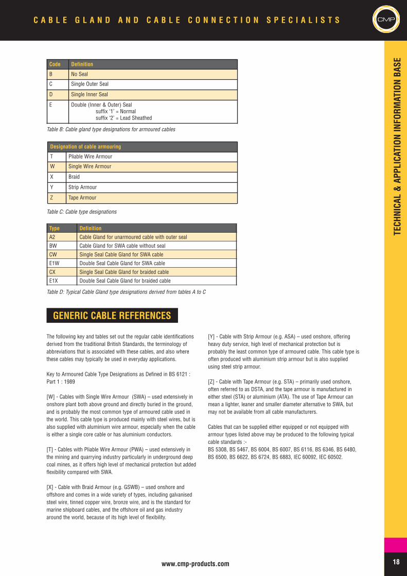
Cable Gland Construction utilising Displacement Seal
This type of seal is usually employed in a cable gland that utilises a 3stage ‘Step by Step’ sequential make off, where the tightening of thearmour termination is separated from the activation of the inner seal.This enables the effectiveness of the seal on the cable inner beddingto be tested before the armour is terminated. This means that unlikeother designs the user is able to determine that the engagement ofthe seal on the cable inner bedding is not too light and not too heavy,affording some level of control over the installation.
It can be noted that this displacement seal arrangement is thestandard method of sealing on the cable inner bedding adopted byCMP Products.
Cable Gland Construction utilising CompensatingDisplacement Seal (CDS) System
The Compensating Displacement Seal system is designed to allowusers to fully tighten the cable gland components together everytime, without damaging the cable. The use of an internalcompensator enables the CDS arrangement to be fully tightenedregardless of the cable diameter. This unique approach offers asolution that allows the installation personnel to carry out theirobjectives to schedule without the likelihood of re-work potentiallyarising from over tightening.
The unique Compensating Displacement Seal (CDS) system is adesign patented by CMP Products.
Industry Standard Cable Gland Designations
Cable Glands may be designed, tested and manufactured to variousstandards around the world, but since CMP Products is a longestablished UK based manufacturer, it just so happens that part of itshistory includes close participation in the development of BritishStandards for these products.
The British Standard BS 6121, and its predecessor BS 4121, havemore than 30 years of exposure in meeting real life industrysituations, not just in the UK but also around the world.
In fact BS 6121 also established the industry standard cable glandtype designations that still prevail today for simple cable glandidentification. It should be noted however that the type designationfor a given cable gland product does not determine the precisemethod of sealing adopted.
Type Definition
A1 For unarmoured cable with an elastomeric or plastic outer sheath, with sealing function between the cable sheath and thesealing ring of the cable gland.
A2 As type A1, but with seal protection degree IP66
A3 As type A1, but with an electrical bond for the metallic inner screen
Table A: Cable gland type designations for unarmoured cables
BS 6121 DefinitionsBelow are tables composed from data included in BS 6121 : Part 1 : 1989 :-
SeparateTighteningActions
Displacement Seal
Separate Body Tightening
CompensatingDisplacementSeal System
Compensator DisplacementSeal
TECHNICAL&APPLICATIONINFORM
ATIONBASE
18www.cmp-products.com
CMPC A B L E G L A N D A N D C A B L E C O N N E C T I O N S P E C I A L I S T S
Code Definition
B No Seal
C Single Outer Seal
D Single Inner Seal
E Double (Inner & Outer) Sealsuffix ‘1’ = Normalsuffix ‘2’ = Lead Sheathed
Table B: Cable gland type designations for armoured cables
Designation of cable armouring
T Pliable Wire Armour
W Single Wire Armour
X Braid
Y Strip Armour
Z Tape Armour
Table C: Cable type designations
Type Definition
A2 Cable Gland for unarmoured cable with outer seal
BW Cable Gland for SWA cable without seal
CW Single Seal Cable Gland for SWA cable
E1W Double Seal Cable Gland for SWA cable
CX Single Seal Cable Gland for braided cable
E1X Double Seal Cable Gland for braided cable
Table D: Typical Cable Gland type designations derived from tables A to C
GENERIC CABLE REFERENCES
The following key and tables set out the regular cable identificationsderived from the traditional British Standards, the terminology ofabbreviations that is associated with these cables, and also wherethese cables may typically be used in everyday applications.
Key to Armoured Cable Type Designations as Defined in BS 6121 :Part 1 : 1989
[W] - Cables with Single Wire Armour (SWA) – used extensively inonshore plant both above ground and directly buried in the ground,and is probably the most common type of armoured cable used inthe world. This cable type is produced mainly with steel wires, but isalso supplied with aluminium wire armour, especially when the cableis either a single core cable or has aluminium conductors.
[T] - Cables with Pliable Wire Armour (PWA) – used extensively inthe mining and quarrying industry particularly in underground deepcoal mines, as it offers high level of mechanical protection but addedflexibility compared with SWA.
[X] - Cable with Braid Armour (e.g. GSWB) – used onshore andoffshore and comes in a wide variety of types, including galvanisedsteel wire, tinned copper wire, bronze wire, and is the standard formarine shipboard cables, and the offshore oil and gas industryaround the world, because of its high level of flexibility.
[Y] - Cable with Strip Armour (e.g. ASA) – used onshore, offeringheavy duty service, high level of mechanical protection but isprobably the least common type of armoured cable. This cable type isoften produced with aluminium strip armour but is also suppliedusing steel strip armour.
[Z] - Cable with Tape Armour (e.g. STA) – primarily used onshore,often referred to as DSTA, and the tape armour is manufactured ineither steel (STA) or aluminium (ATA). The use of Tape Armour canmean a lighter, leaner and smaller diameter alternative to SWA, butmay not be available from all cable manufacturers.
Cables that can be supplied either equipped or not equipped witharmour types listed above may be produced to the following typicalcable standards :-BS 5308, BS 5467, BS 6004, BS 6007, BS 6116, BS 6346, BS 6480,BS 6500, BS 6622, BS 6724, BS 6883, IEC 60092, IEC 60502.
TECHNICAL&APPLICATIONINFORM
ATIONBASE
19 www.cmp-products.com
CMP C A B L E G L A N D A N D C A B L E C O N N E C T I O N S P E C I A L I S T S
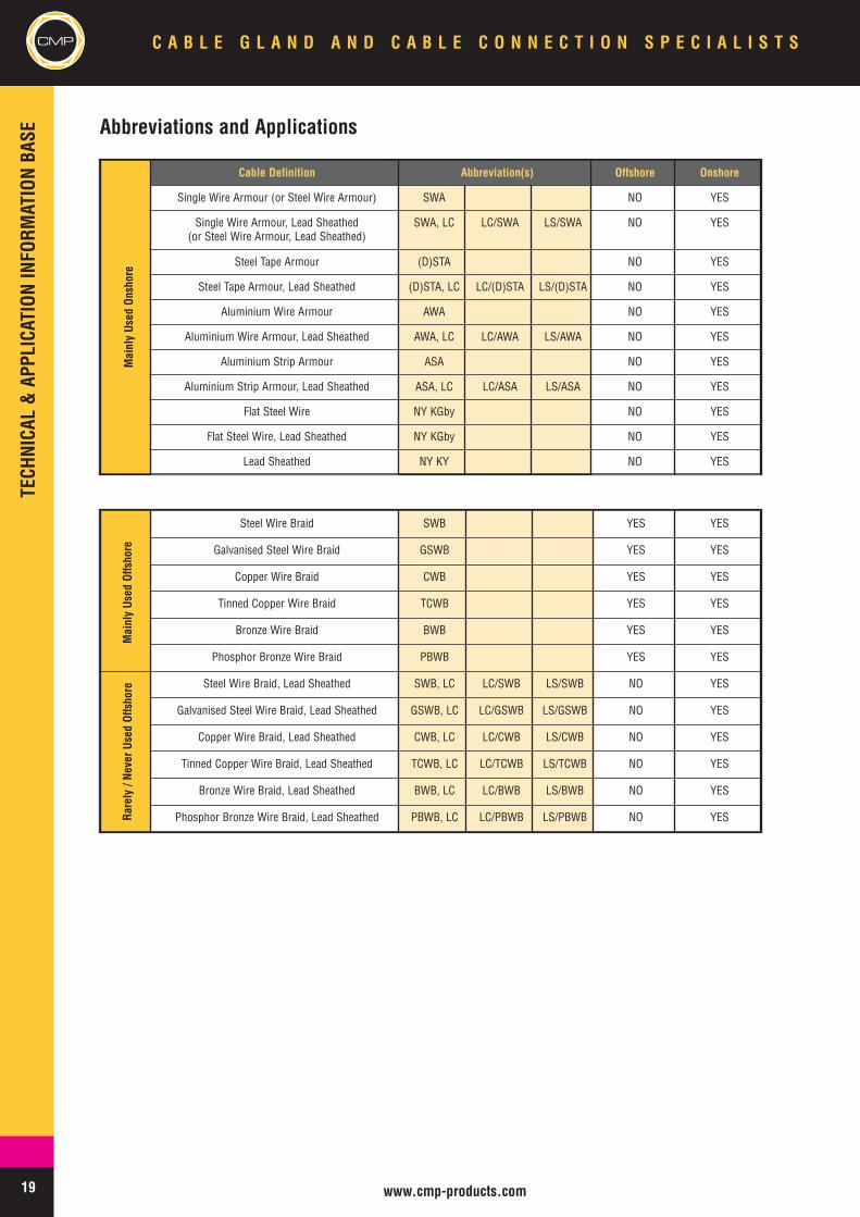
Abbreviations and Applications
Cable Definition Abbreviation(s) Offshore Onshore
Single Wire Armour (or Steel Wire Armour) SWA NO YES
Single Wire Armour, Lead Sheathed(or Steel Wire Armour, Lead Sheathed)
SWA, LC LC/SWA LS/SWA NO YES
Steel Tape Armour (D)STA NO YES
Steel Tape Armour, Lead Sheathed (D)STA, LC LC/(D)STA LS/(D)STA NO YES
Aluminium Wire Armour AWA NO YES
Aluminium Wire Armour, Lead Sheathed AWA, LC LC/AWA LS/AWA NO YES
Aluminium Strip Armour ASA NO YES
Aluminium Strip Armour, Lead Sheathed ASA, LC LC/ASA LS/ASA NO YES
Flat Steel Wire NY KGby NO YES
Flat Steel Wire, Lead Sheathed NY KGby NO YES
Lead Sheathed NY KY NO YES
Steel Wire Braid SWB YES YES
Galvanised Steel Wire Braid GSWB YES YES
Copper Wire Braid CWB YES YES
Tinned Copper Wire Braid TCWB YES YES
Bronze Wire Braid BWB YES YES
Phosphor Bronze Wire Braid PBWB YES YES
Steel Wire Braid, Lead Sheathed SWB, LC LC/SWB LS/SWB NO YES
Galvanised Steel Wire Braid, Lead Sheathed GSWB, LC LC/GSWB LS/GSWB NO YES
Copper Wire Braid, Lead Sheathed CWB, LC LC/CWB LS/CWB NO YES
Tinned Copper Wire Braid, Lead Sheathed TCWB, LC LC/TCWB LS/TCWB NO YES
Bronze Wire Braid, Lead Sheathed BWB, LC LC/BWB LS/BWB NO YES
Phosphor Bronze Wire Braid, Lead Sheathed PBWB, LC LC/PBWB LS/PBWB NO YES
MainlyUsed
Onshore
MainlyUsed
Offshore
Rarely/ NeverUsed
Offshore
TECHNICAL&APPLICATIONINFORM
ATIONBASE
20www.cmp-products.com
CMPC A B L E G L A N D A N D C A B L E C O N N E C T I O N S P E C I A L I S T S
FIRE PERFORMANCE CABLES
The development of electric cables for fire situations has meant thatFire Performance cables have become an almost everydayrequirement in the construction industry globally, but the generalsubject of fire performance cables can be a complex one. The needfor cables to continue to perform in the event of a fire is moreprevalent today than ever before, and in the case of public buildingsthe need to reduce the toxicity content in the materials used toproduce cables carries equal importance.
The dangers of fire would include the safety of people and thecontinuous functioning of electrical circuits required to maintainsafety. In the case of electric cables their construction may need to
address some or all of the following; fire survival, fire resistance, firepropagation, flame retardancy, smoke emission and toxicity.
Even if the electrical circuit was not the cause of a fire, the electriccable may very well be engulfed in a fire that has started elsewhere.Consequently the compounds that the cable is produced from shouldnot contribute to the fire, help spread it, or emit gases duringcombustion that could harm people or damage equipment. Anotheraspect to consider is that the density of smoke generated in the eventof a fire should not be sufficient to obscure emergency exit signs.Most cable standards therefore include some kind of fire performanceand testing requirements, but there are many in existence.
Fire Test Standards for Cables
Here are a selection of standards used in relation to fire tests for cables :-
BS 6387 : Performance requirements for cables required to maintain circuit integrity under fire conditionsEN 50266 : Common test methods for cables under fire conditions - Test for vertical flame spread of vertically-mounted
bunched wires or cablesEN 50267 : Common test methods for cables under fire conditions - Tests on gases evolved during combustion of
materials from cablesEN 50200 : Method of test for resistance to fire of unprotected small cables for use in emergency circuitsBS 8434-1 : Methods of test for assessment of the fire integrity of electric cables. Test for unprotected small cables for
use in emergency circuits. (EN 50200 with addition of water spray)BS 8434-2 : Methods of test for assessment of the fire integrity of electric cables. Test for unprotected small cables for
use in emergency circuits. (EN 50200 with a 930°C flame and with water spray)IEC 60331 : Tests for electric cables under fire conditionsIEC 60332 : Tests on electric and optical fibre cables under fire conditionsIEC 60754 : Test on gases evolved during combustion of materials from cablesIEC 61034 : Measurement of smoke density of cables burning under defined conditions.
HALOGEN FREE OR LOW SMOKE & FUME MATERIALS
As outlined in the previous subject certain cable types are designedwith the performance capability of surviving fire conditions for aspecified period, whilst other cable types may be manufactured usingpolymer compounds that generate lower smoke and fume emissions.In such cases the cables may be identified as being Halogen Free,Low Smoke & Fume (LSF), Low Smoke Zero Halogen (LSZH), orZero Halogen Low Smoke (ZHLS).
These compare favourably with traditional electric cables that werelikely to generate noxious emissions of gases in fire situations, thatmay have been manufactured and installed many years ago, prior tothe introduction of the most recent cable standards and thedevelopment of new environmentally friendly compounds.
It is equally important that the materials used in the manufacture ofcable management products, including cable cleats, cable clampscable glands, their seals, and any shrouds that are required to befitted, can offer the same high level of compliance in the way of lowersmoke and fume emissions.
Some cables, but not all, that bear Low Smoke & Fume and /or ZeroHalogen characteristics may have an inner cable bedding that isextruded from a compound which has not been fully cured during themanufacturing process. This is often referred to as a soft bedding,and this itself brings an additional factor to consider when selectingappropriate cable sealing glands to suit cables having thischaracteristic.
TECHNICAL&APPLICATIONINFORM
ATIONBASE
21 www.cmp-products.com
CMP C A B L E G L A N D A N D C A B L E C O N N E C T I O N S P E C I A L I S T S
CMP SOLO LOW SMOKE & FUME (LSF) MATERIALS
CMP Products has been instrumental in the field of providing cablemanagement solutions produced from materials that are designed toreduce the risk of toxic emissions and smoke inhalation. Thesesolutions or products include cable cleats, cable clamps, cableglands, and their accessories, all of which are required to meet thesame exacting standards as is applied to electric cables. In the pastcable gland seals were generally manufactured form Neoprenematerials (e.g. Polychloroprene or Chloroprene CR), although thereare varying grades and types of Neoprene materials on the market,and shrouds were most commonly produced from PVC (Polyvinylchloride). At the time when these materials were first selected forcertain applications they may well have been chosen because theywere the best or the most readily available material source to suit theintended use. Now however with the benefit of hindsight, and with agreater emphasis on environmentally friendly substances, taking intoaccount the health & safety requirements for people occupying publicbuildings or being in public places, the commonly used materials ofthe past have become less attractive for use in cable managementproducts.
Now, with the availability of a new generation of improved materialcompounds and formulas it has been possible to draw comparisonsidentifying that Neoprene and PVC would no longer be the first choicewhen it comes to smoke and fume emissions. With its SOLO LSFbrand of Low Smoke & Fume elastomeric compound formula, CMPProducts has helped spearhead the drive in the industry, byspecification, to ensure a higher degree of protection in terms ofreduced levels of noxious fumes and toxic emissions generated fromcable related products in the event of a fire.
CMP Products has had the material used in the CMP LSF Seals andShrouds independently 3rd Party tested to EN 50267-2-1, the teststandard applied to cables to determine the amount of halogen acidgas evolved during combustion of materials. The objective of the testis to identify whether the halogen acid gas evolved from the materialis within the maximum 5mg/g permitted by the standard. CMPProducts declares that the CMP SOLO LSF material emits less than5mg/g acid gas, which satisfies the requirements of this EN 50267-2-1, and the results of the Fire Laboratory tests confirm that material isclassified as “Halogen Free”.
For clarification, the EN 50267-2-1 standard reveals that :-
Materials found to emit <150 mg/g (<15%) halogen acid gas duringcombustion are classed as Low Halogen
Materials found to emit <5 mg/g (<0.5%) halogen acid gas duringcombustion are classed as Halogen Free
For further information please refer to EN 50267-2-1 : 1999 -Common Test Methods for Cables Under Fire Conditions - Tests onGases Evolved During Combustion of Materials From Cables - Part 2-1: Procedures - Determination of the Amount of Halogen Acid Gas
The CMP SOLO products initially witnessed significant demandduring the new construction of public buildings such as airports,tunnels, MRT systems, office blocks, shopping centres, sports stadia,libraries etc. but the maturing market demand has also extended towider areas other than the above.
One particularly significant application has been the use of CMPSOLO LSF range within the underground railway system in the UK’scapital city. Throughout London Underground Limited (LUL) there isan overriding priority for the safety of passengers. One of the greatestdangers in any deep bore metro system is the difficulty of evacuatingcustomers and staff in the event of a major fire. It has therefore beenLUL's policy for many years to control the fire performance ofmaterials used underground through its own requirements in additionto those required by legislation. Although this is not a new situation,LUL operates a process, within its fire safety department, thatevaluates the properties of compounds used in cable and cablerelated products against specified materials fire performancerequirements. CMP Products has extensive experience of meeting theconditions of these tests and supplying various products to such asafety critical area.
One of the advantages of using new polymer compound formulas forthe manufacture of cable gland seals and shrouds etc. is that theycan also offer additional benefits in the way of performance in severalkey areas, such as :-
• Increased Resistance to Ozone• Improved UV Resistance• Improved Oil Resistance• Increased Maximum Operating Temperatures• Improved Minimum Operating Temperatures• Reduced Shore Hardness
TECHNICAL&APPLICATIONINFORM
ATIONBASE
22www.cmp-products.com
CMPC A B L E G L A N D A N D C A B L E C O N N E C T I O N S P E C I A L I S T S
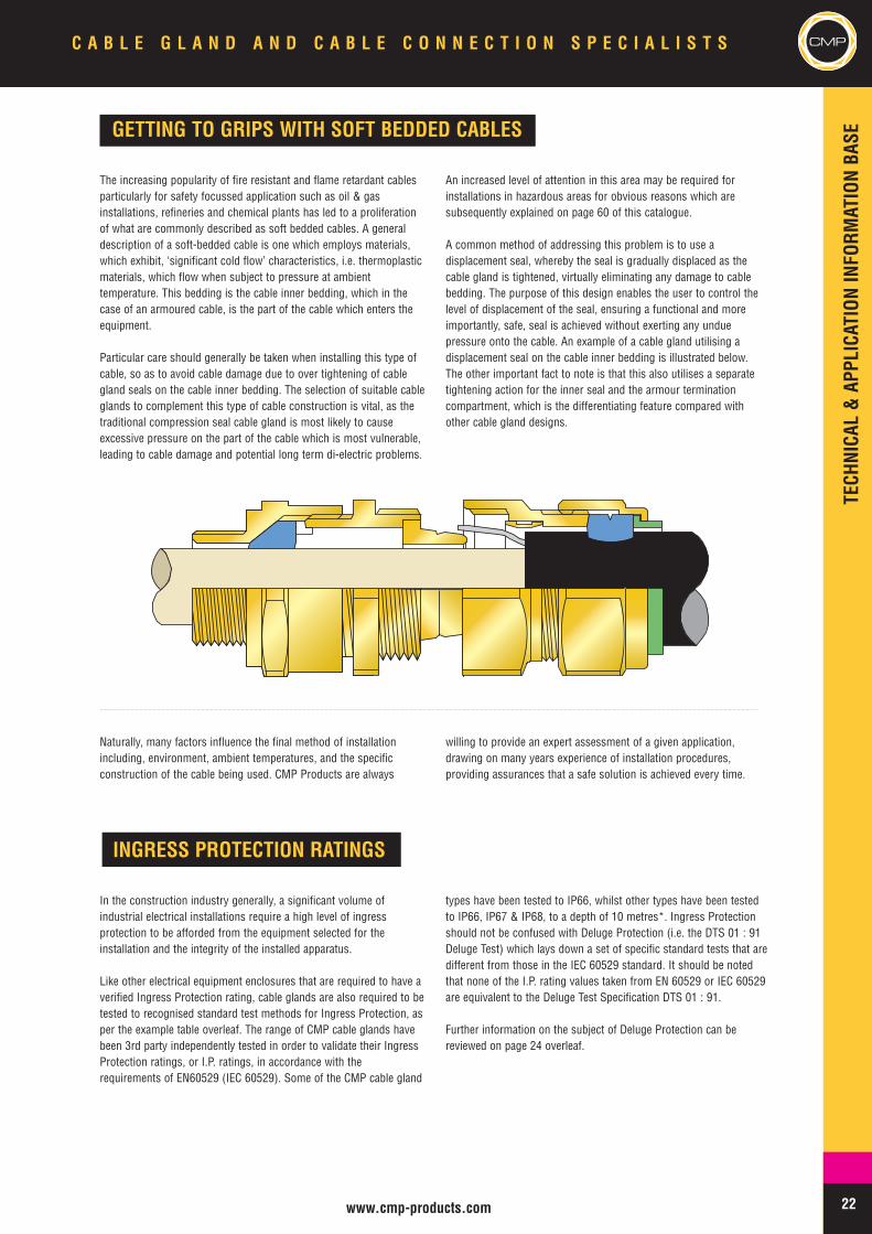
GETTING TO GRIPS WITH SOFT BEDDED CABLES
The increasing popularity of fire resistant and flame retardant cablesparticularly for safety focussed application such as oil & gasinstallations, refineries and chemical plants has led to a proliferationof what are commonly described as soft bedded cables. A generaldescription of a soft-bedded cable is one which employs materials,which exhibit, ‘significant cold flow’ characteristics, i.e. thermoplasticmaterials, which flow when subject to pressure at ambienttemperature. This bedding is the cable inner bedding, which in thecase of an armoured cable, is the part of the cable which enters theequipment.
Particular care should generally be taken when installing this type ofcable, so as to avoid cable damage due to over tightening of cablegland seals on the cable inner bedding. The selection of suitable cableglands to complement this type of cable construction is vital, as thetraditional compression seal cable gland is most likely to causeexcessive pressure on the part of the cable which is most vulnerable,leading to cable damage and potential long term di-electric problems.
An increased level of attention in this area may be required forinstallations in hazardous areas for obvious reasons which aresubsequently explained on page 60 of this catalogue.
A common method of addressing this problem is to use adisplacement seal, whereby the seal is gradually displaced as thecable gland is tightened, virtually eliminating any damage to cablebedding. The purpose of this design enables the user to control thelevel of displacement of the seal, ensuring a functional and moreimportantly, safe, seal is achieved without exerting any unduepressure onto the cable. An example of a cable gland utilising adisplacement seal on the cable inner bedding is illustrated below.The other important fact to note is that this also utilises a separatetightening action for the inner seal and the armour terminationcompartment, which is the differentiating feature compared withother cable gland designs.
Naturally, many factors influence the final method of installationincluding, environment, ambient temperatures, and the specificconstruction of the cable being used. CMP Products are always
willing to provide an expert assessment of a given application,drawing on many years experience of installation procedures,providing assurances that a safe solution is achieved every time.
INGRESS PROTECTION RATINGS
In the construction industry generally, a significant volume ofindustrial electrical installations require a high level of ingressprotection to be afforded from the equipment selected for theinstallation and the integrity of the installed apparatus.
Like other electrical equipment enclosures that are required to have averified Ingress Protection rating, cable glands are also required to betested to recognised standard test methods for Ingress Protection, asper the example table overleaf. The range of CMP cable glands havebeen 3rd party independently tested in order to validate their IngressProtection ratings, or I.P. ratings, in accordance with therequirements of EN60529 (IEC 60529). Some of the CMP cable gland
types have been tested to IP66, whilst other types have been testedto IP66, IP67 & IP68, to a depth of 10 metres*. Ingress Protectionshould not be confused with Deluge Protection (i.e. the DTS 01 : 91Deluge Test) which lays down a set of specific standard tests that aredifferent from those in the IEC 60529 standard. It should be notedthat none of the I.P. rating values taken from EN 60529 or IEC 60529are equivalent to the Deluge Test Specification DTS 01 : 91.
Further information on the subject of Deluge Protection can bereviewed on page 24 overleaf.
TECHNICAL&APPLICATIONINFORM
ATIONBASE
23 www.cmp-products.com
CMP C A B L E G L A N D A N D C A B L E C O N N E C T I O N S P E C I A L I S T S
Protection against Solid Foreign Objectsand Access to Hazardous Parts Protection against Liquids
Illustration Method Explanation Illustration Method
0 - Non-protected Non-protected 0 - Non-protected
1Protected against solid foreignobjects of 50mm diameter
and greater
Protected against access tohazardous parts with the back
of a hand1 Protected against drops of
water falling vertically
2Protected against solid foreignobjects of 12.5mm diameter
and greater
Protected against access tohazardous parts with a finger 2
Protected against drops ofwater falling at up to 15º
from the vertical
3Protected against solid foreignobjects of 2.5mm diameter
and greater
Protected against access tohazardous parts with a tool 3
Protected against sprayingwater at up to 60º from the
vertical
4Protected against solid foreignobjects of 1.0mm diameter
and greater
Protected against access tohazardous parts with a wire 4 Protected against splashing
water from all directions
5 Dust-protected Protected against access tohazardous parts with a wire 5 Protected against jet of water
from all directions
6 Dust-tight Protected against access tohazardous parts with a wire 6 Protected against jet of water
of similar force to heavy seas
7 Protected against the effectsof immersion
8Protected against prolongedeffects of immersion underpressure to a specified depth
* Please refer to appropriate catalogue pages for specific Ingress Protection ratings according to their design and construction.
In addition to the Ingress Protection tests carried out as standard on the CMP range of Cable Glands, selected products have additionally beentested to meet the requirements of NEMA 4X in accordance with North American standards. The following table is provided for comparisonpurposes between typical NEMA and IEC 60529 ratings.
FirstDigit
Second
Digit
ENVIRONMENTAL RATINGS
NEMA RATING IEC 60529 RATING SOLIDS WATER1 IP23 Objects > 12.5 mm Spraying2 IP30 Objects > 2.5 mm Spraying3 IP64 Dust-Tight Splashing3R IP32 Objects > 2.5 mm Drips at 15°3S IP64 Dust-Tight Splashing4 P65-66 Dust-Tight Jet to Power Jet4X IP66 Dust-Tight Power Jets6 IP67 Dust-Tight Temporary Immersion6P IP68 Dust-Tight Prolonged Immersion12 IP55 Dust-Protection Jets13 IP65 Dust-Tight Jets
Note: NEMA Ratings can be converted to IEC IP ratings but IEC IP Ratings CANNOT be converted to NEMA Ratings.
TECHNICAL&APPLICATIONINFORM
ATIONBASE
50mm
112.5mm
22.5mm
11mm
1m
15cm
(min
)
m
Ingress Protection Matrix
24www.cmp-products.com
CMPC A B L E G L A N D A N D C A B L E C O N N E C T I O N S P E C I A L I S T S
DELUGE PROTECTION SPECIFICATION DTS 01:91
Offshore platforms are subject to routine testing of their emergencydeluge systems with up to 30,000 litres of water per minute beingunloaded in the modules making up the process areas. To keep pacewith this development, equipment manufacturers have had to havetheir products tested for such conditions.
The DTS01 Test Specification was developed by Shell UK inconjunction with ERA Technology, based in Leatherhead, Surrey.Since its inception in 1991 it has become widely accepted by allmajor offshore operating companies as the standard to meet inrespect of deluge protection.
Electrical equipment on offshore installations may be located in areaswhich are equipped with the emergency deluge facilities. Exposure ofsuch equipment must not lead to water ingress in quantities whichcould cause the equipment to become a potential source of ignitionwhen exposed to a flammable atmosphere.
The introduction of DTS 01 created a standard method of tests to becarried out on electrical equipment, components, devices and motorsto simulate their exposure to realistic water deluge conditions andestablish their potential hazard. This was considered to far outreachany of the Ingress Protection tests that were already performed underthe IEC 60529 standard, as longer term exposure to the typicalmarine and offshore environment often brought with it more onerousconditions than those anticipated by IEC 60529.
The Deluge Test utilises a slat water solution controlled at pre-determined temperatures and this is applied using medium velocitynozzles at a pressure in the range of 3.5 to 4.5 bar. To make the testmost realistic an additional pre-conditioning is applied to the samplesto be tested. This pre-conditioning can optionally consist of eitherexposure to vibration or thermal ageing depending upon the nature ofthe equipment under test. The purpose of this pre-conditioning is tosimulate accelerated ageing of the seals used in the equipment priorto the tests being conducted, which is considered to be equivalent to20 years of service at normal operating temperatures.
With cable glands it is more logical to have their sealing ringssubjected to the rapid thermal ageing rather than vibration exposuretests. The cable glands and sealing rings are conditioned in ahumidity chamber for 14 days, at 95ºC and a relative humidity of90%.They are then further subject to a temperature of 100ºC for 14days, prior to the deluge test commencing. Then they are installedinto equipment which is heated to simulate its operating temperatureat a typical ambient, and are subjected to a cold water deluge spray,creating an internal vacuum, which would draw water through thecable glands into the equipment if the deluge seal did not perform.
At CMP, the ageing of cable gland seals, taking into account suchthings as the heat cycling effects of electrical apparatus, is seen ashaving a major bearing on proving true long term protection againstdeluge conditions. Significantly, CMP has had the confidence in
having a number of its innovative Cable Glands, including the T3CDSrange tested to this onerous requirement. Under the close third partyscrutiny, and the rapid ageing specification described above, CMPhas been able to demonstrate the durability of its products in theseconditions, whereas not all cable gland manufacturers have been ableto meet the exacting demands of this criterion.
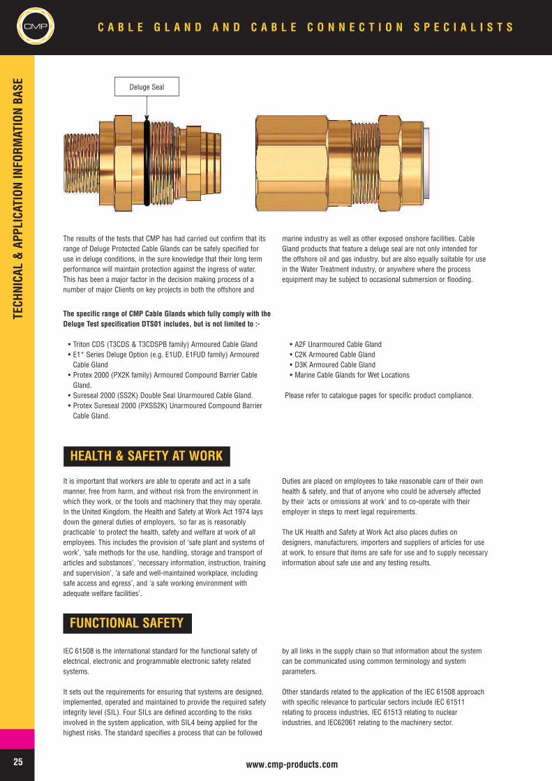
One of the features of a true deluge proof cable gland for armoured,or braided, cables which makes it stands out above other standardcable glands is the inclusion of a deluge seal. This deluge seal isapplied in the joint where the cable gland body terminates the cablebraid armour and it is included for protection against a specific andcostly problem that has been experienced in offshore environmentsaround the world. Prior to the introduction of high poweredemergency deluge systems the problem that was experienced in themost hostile offshore situations was frequent yet often prematurecable braid armour corrosion. This corrosion was occurring due tothe ingress of water through the armour termination compartment ofthe cable gland, even when a cable gland had passed an IngressProtection test of IP66 or higher. Following investigation, theevidence pointed to the fact that during energising and de-energisingof the electrical equipment the heat cycling effects were causingpositive and negative changes in the internal pressure of theequipment. This change in pressure was in turn causing water towork its way around the threaded joints in the cable gland via acapillary action that meant the cable braid would in time becontaminated by salt water. This often led to rapid deterioration andeven corrosive breakdown of the cable braid that was commonlymade of Galvanised Steel Wire. In the experience of major oil and gasoperating companies, this known problem was first discovered as aserious problem when earth continuity checks highlighted the factthat there was no continuity through the cable at all.
Tackling this serious problem and also going one step further inaddressing the requirements of the Deluge Test at the same time,when potentially more frequent exposure to salt water conditionswould result, CMP Products was the first manufacturer to introduce aDeluge Proof cable gland design. This design of course featured apositive sealing function between the cable gland components thatmake up the armour termination joint, like the example shown below.It should be recognised that whilst it may be possible to obtain anIP67 or IP68 rating with a cable gland that does not include a delugeseal feature, it is highly unlikely that such a product would pass theconditions of the DTS 01 : 91 Deluge Test and realistically ensurelong term cable armour preservation in offshore or marineinstallations.
TECHNICAL&APPLICATIONINFORM
ATIONBASE
25 www.cmp-products.com
CMP C A B L E G L A N D A N D C A B L E C O N N E C T I O N S P E C I A L I S T S
FUNCTIONAL SAFETY
IEC 61508 is the international standard for the functional safety ofelectrical, electronic and programmable electronic safety relatedsystems.
It sets out the requirements for ensuring that systems are designed,implemented, operated and maintained to provide the required safetyintegrity level (SIL). Four SILs are defined according to the risksinvolved in the system application, with SIL4 being applied for thehighest risks. The standard specifies a process that can be followed
by all links in the supply chain so that information about the systemcan be communicated using common terminology and systemparameters.
Other standards related to the application of the IEC 61508 approachwith specific relevance to particular sectors include IEC 61511relating to process industries, IEC 61513 relating to nuclearindustries, and IEC62061 relating to the machinery sector.
The results of the tests that CMP has had carried out confirm that itsrange of Deluge Protected Cable Glands can be safely specified foruse in deluge conditions, in the sure knowledge that their long termperformance will maintain protection against the ingress of water.This has been a major factor in the decision making process of anumber of major Clients on key projects in both the offshore and
marine industry as well as other exposed onshore facilities. CableGland products that feature a deluge seal are not only intended forthe offshore oil and gas industry, but are also equally suitable for usein the Water Treatment industry, or anywhere where the processequipment may be subject to occasional submersion or flooding.
The specific range of CMP Cable Glands which fully comply with theDeluge Test specification DTS01 includes, but is not limited to :-
• Triton CDS (T3CDS & T3CDSPB family) Armoured Cable Gland• E1* Series Deluge Option (e.g. E1UD, E1FUD family) ArmouredCable Gland
• Protex 2000 (PX2K family) Armoured Compound Barrier CableGland.
• Sureseal 2000 (SS2K) Double Seal Unarmoured Cable Gland.• Protex Sureseal 2000 (PXSS2K) Unarmoured Compound BarrierCable Gland.
• A2F Unarmoured Cable Gland• C2K Armoured Cable Gland• D3K Armoured Cable Gland• Marine Cable Glands for Wet Locations
Please refer to catalogue pages for specific product compliance.
HEALTH & SAFETY AT WORK
It is important that workers are able to operate and act in a safemanner, free from harm, and without risk from the environment inwhich they work, or the tools and machinery that they may operate.In the United Kingdom, the Health and Safety at Work Act 1974 laysdown the general duties of employers, 'so far as is reasonablypracticable' to protect the health, safety and welfare at work of allemployees. This includes the provision of ‘safe plant and systems ofwork’, ‘safe methods for the use, handling, storage and transport ofarticles and substances’, ‘necessary information, instruction, trainingand supervision’, ‘a safe and well-maintained workplace, includingsafe access and egress’, and ‘a safe working environment withadequate welfare facilities’.
Duties are placed on employees to take reasonable care of their ownhealth & safety, and that of anyone who could be adversely affectedby their 'acts or omissions at work' and to co-operate with theiremployer in steps to meet legal requirements.
The UK Health and Safety at Work Act also places duties ondesigners, manufacturers, importers and suppliers of articles for useat work, to ensure that items are safe for use and to supply necessaryinformation about safe use and any testing results.
Deluge Seal
TECHNICAL&APPLICATIONINFORM
ATIONBASE
26www.cmp-products.com
CMPC A B L E G L A N D A N D C A B L E C O N N E C T I O N S P E C I A L I S T S
ELECTRICAL SAFETY IN THE WORK PLACE
Electrical Safety in the workplace should always be observed andnever be underestimated. Local codes of practice or regulations maybe in force to ensure that safety is maintained to eliminate thepossibility of accidents arising from the danger of electricity. Thesedangers would include Electric Shock, Burns, Fire, Explosion andArcing. In the United Kingdom the the Electricity Safety, Quality andContinuity Regulations 2002, introduced under Statutory InstrumentNo. 2665, and the Electricity at Work Regulations 1989 (EAWRegulations), which came into force on 1 April 1990,comprehensively deals with this subject. The purpose of these farreaching regulations is to ensure that the necessary precautions aretaken against the risk of death or personal injury at work. Thisinvolves the imposition of duties on employers and employees inrespect of electrical systems, equipment and conductors and theinstallation of the same.
Other national and international standards will also exist and theseshould be observed when required. IEC standards standards relatedto electrical safety include :-
IEC 61140 : Protection against electric shock – Common aspects forinstallation and equipment.
This standard covers the Basic rules, Requirements for protectiveprovisions, Description of protective measures, Combination ofprotective measures, and special operating and servicing conditions
IEC 60364-4-41 : Low-voltage electrical installations - Part 4-41:Protection for safety - Protection against electric shock
This standard specifies essential requirements regarding protectionagainst electric shock, including basic protection (protection againstdirect contact) and fault protection (protection against indirectcontact) of persons and livestock.
IEC 60364-5-54 : Electrical installations of buildings - Part 5-54 :Selection and erection of equipment – Earthing arrangements,protective conductors and equipotential bonding.
This standard covers the basic requirements for earthing and bondingfor safety purposes, and Protective conductors.
WIRING REGULATIONS AND EARTHING REQUIREMENTS
It is important to realise that regulations may differ from region toregion or country to country and the need to comply with the localregulations or requirements should equally be recognised. There areseveral different standards in existence that may need to be followed,and in the United Kingdom BS 7671:2001, the IEE Wiring Regulations16th Edition, and BS 7430:1998, the code of practice for earthing, arethe applicable prevailing industry standards.
Depending on the situation it may also be necessary to follow the IECstandards, e.g. IEC 60364 - Electrical Installation in Buildings.Outside of the IEC arena, both the standards and the terminologywhich they use may differ considerably from the norm. In NorthAmerica, for example “earthing” would normally be referred to as“grounding”.
The earthing of both the electrical systems, and also the metallicstructures that they may come into contact with is a safety criticalactivity for obvious reasons. In the United Kingdom the BS7430:1998 the code of practice for earthing, provides guidance onearthing of electrical supply systems, electrical installations andconnected equipment, for the proper operation of systems and theprotection of life. This covers basic principles, earthing methods andmost general applications.
When using armoured cables (or conduit), both in onshore andoffshore or marine situations, any metallic parts of the cable (orconduit) must be earthed, and this also applies to the lead coveringused in lead sheathed cables. Wherever armoured cables are used itis normal practice to terminate the metallic armour, and / or leadcover (lead sheath) in the body of a metallic cable gland.
In accordance with BS 7671:2001, the IEE Wiring Regulations 16thEdition, both the cable and the accessories used for its connectionmust be tested to ensure compliance with the required safety levels.Cable glands and their fixing accessories and earth tags must beselected correctly to ensure that any risk of electric shock topersonnel from coming into contact with live parts due to inferiorearth connection is avoided. These earthing components musttherefore be able to meet the minimum short circuit fault currentwithstand tests of the associated cable, and also be installed bycompetent personnel in line with good engineering practices
The cable armour is primarily for mechanical protection, and asalready stated, this metallic armour must be effectively earthed. Ingeneral, the armour wire current carrying capacity must be equal to50% of that of the largest current carrying conductor in the cable.The cable must be tested to determine its short circuit earth faultcurrent rating, with the earth fault current being carried by the cablearmour wires. Users should refer to the cable manufacturers designdata for the short circuit fault current carrying capacity of the armourwires of each cable.
TECHNICAL&APPLICATIONINFORM
ATIONBASE
27 www.cmp-products.com
CMP C A B L E G L A N D A N D C A B L E C O N N E C T I O N S P E C I A L I S T S
SWA cables
Cable glands connected to SWA cables must be able to provide earthcontinuity from the termination point of the armour in the cable glandbody through to the equipment, if the enclosure is metallic, or via ametallic gland plate that is bonded to an external earth point, and / ordirectly to an external earth point via an earth tag. In the interests ofsafety most earthing systems associated with armoured cables willutilise a number of directly grounded external earth link cablesconnected to the earth tag which is in contact with the cable gland.Usually the cable would be earthed at one of its two ends as aminimum, and this approach ensures that in the event of a shortcircuit or earth fault in the cable, the quickest and most direct routeto ground will be achieved as a result of the design philosophyadopted. When multiple cable entries are required in non-metallicenclosures (e.g. GRP terminal box) that do not have an external earthpoint, the user may prefer to engage an external earth cable betweeneach metallic cable gland via an earth tag. At least one of the earthtags would also be used to connect an earth cable directly to ground.This method of providing earth continuity is sometimes referred to asa “daisy-chain” arrangement.
The earth tag described above must also be tested to ensure that itcan withstand the equivalent short circuit earth fault current testrating of the cable and cable gland, otherwise the system will nothave adequate (safety) earth protection.
LC / SWA or LC / PVC / SWA cables
In addition to the standard requirements for SWA cables, there is aset of special guidelines for lead covered cables intended for directburial in the ground of hydrocarbons processing and refinery sites.These guidelines were introduced in the UK by the Oil CompaniesMaterial Association (OCMA) and responsibility for these wassubsequently transferred to EEMUA, the Engineering Equipment andMaterial Users Association. The EEMUA Publication 133“Specification for Underground Armoured Cable Protected AgainstSolvent Penetration and Corrosive Attack” defines the requirementsof the petroleum industry for underground lead-sheathed cables foruse where protection against solvent penetration or corrosive attackis required.When the cable is LC / PVC / SWA the addition of the lead sheathintroduces another metallic part of the cable that could effectivelybecome live in the event of an earth fault or induced voltage and thismust also be earthed. Any metallic parts used to terminate the leadsheath as part of the earth path must also be tested and documentedto demonstrate that adequate levels of protection are maintained. Inthe case of LC / SWA cables the earth fault short circuit levels will beincreased due to the parallel earth path existing between the armourwires and the lead sheath. It is important therefore that the wholecable gland and earth tag arrangement is tested on lead sheathedcable to ensure that the arrangement can withstand the overall affectsresulting from short circuit in the cable armour / lead sheath.
If the cable glands and accessories chosen have not been tested, andare incorrect the connection of the earth circuit via the cable armourwill become the weakest link in the system, and could result inpotential fatality, lost time incident (LTI) or other accident.
SAFE EARTHING SYSTEMS
The need for safe earthing systems has been around for many yearssince the early development of the electrical power industry, but themuch wider spread use of electrical energy for every imaginableapplication merely increases the need for an increase in the safetyassociated with earthing. In the United Kingdom the BS 7430:1998code of practice for earthing should be observed.
Before we can discuss the problem of how to provide adequate andsafe earthing systems, we should first consider the causes of earthfaults. These can be caused by Lightning, Earth Leakage Current &Voltage, Differential Voltage Faults, Cable Capacitance Discharge,Circulating Currents, Fault Conditions from Loose or InadequateConnections, or Human (Installation) errors, including the absence ofthe correct electrical protection devices, the installation of incorrectprotection devices, incorrect installation, or failure to observeregulations. Good quality and reliable earthing systems are thereforeessential to protect against the situations arising as previouslymentioned.
Both cable manufacturers and cable gland manufacturers must caterin their design for the eventuality of an earth fault being carried viathe cable armour, which is primarily intended for mechanicalprotection, but which may also be able to double up as the safemeans to carry the earth fault conditions to ground. This may be thecase with some Low Voltage cables as well as Medium & HighVoltage cables, but in the latter two cases a higher fault current maybe expected to occur in these cables.
Each cable that is expected to be able to carry an earth fault via itsintegral armour would have a rated current carrying capacity.
When a metallic cable gland is connected to an equipment enclosurewhich may also be metallic, or alternatively non-metallic, an Earth Tagmay be required to ground the earth circuit via an Earth Link Cable orconnect to another piece of equipment. These are intended to providean earth bond connection as specified in BS 6121 : Part 5 : 1993, andsubsequently EN 50262.
TECHNICAL&APPLICATIONINFORM
ATIONBASE
28www.cmp-products.com
CMPC A B L E G L A N D A N D C A B L E C O N N E C T I O N S P E C I A L I S T S
Here are the Short Circuit Fault Current Rating values for CMP slip on Earth Tags, when installed between the cable gland and equipment :-
CMP Brass Earth Tags
CMP CIEL Cable Glands
The following fault current ratings apply to the CMP CIEL design type cable glands.
In the event that MV and HV cables have a High Fault CurrentCarrying Capacity, via their Single Wire Armour configurations, thefault rating of the cable may be higher than those of the standardCMP Earth Tags. In this case it would not be advisable to usestandard earth tags as it is important to match the rated fault currentof the earth tag to the corresponding fault current rating of the cablearmour. If the rating of the earth tag is greater than the fault currentrating of the mating cable armour then using the earth tag would beacceptable, but the situation may be unsafe if the rating of the cablearmour fault current carrying capacity is greater than that of thestandard earth tag.
In such cases the perfect solution to overcome potential over heatingand possible flash over, would be to use the CMP CIEL solutionwhich involves the inclusion of an integral Cast Integral Earth Lugarrangement, in the cable gland assembly. The CMP CIEL range usesthe same principal design concept as a standard CW, E1W, or E2Wcable gland product in terms of sealing and / or hazardous areaprotection, but with additional facility for extra heavy duty earthconnection.
This product design is available in Brass, Nickel Plated Brass, andAluminium, and can be supplied in the Cable Gland Types CW CIEL,CWe CIEL, E1W CIEL, E1FW CIEL, E2W CIEL & E2FW CIEL.
CMP Earth Tag Size Short Circuit Ratings Symmetrical Fault Current (kA) for 1 second
20 3.06
25 4.00
32 5.40
40 7.20
50 10.40
63 10.40
75 10.40
CMP CIEL Gland Size Short Circuit Ratings Symmetrical Fault Current (kA) for 1 second
20S to 40 26.0
50S to 90 43.0
In addition to the recognised causes of earth faults described above,other environmental factors would also have an impact upon theoverall electrical performance, and require reliable safe earthingsystems in order to protect against them. These environmentalconsiderations would include the possibility of ElectromagneticInterference (EMI / RFI), cross talk and induced voltages stemmingfrom the positioning of cables
It has been a known fact for many years in the UK power generationindustry that unless special measures are taken to both segregate thecables in accordance with wiring regulations, and also isolate themetallic cable armour from running in continuous contact throughoutthe whole of the earthing system, interference or electrical noise waslikely to spread around the extent of the plant.
To combat the sometimes intense levels of interference that had beenexperienced in practice, users were able to use the CMP ZEN range ofInsulated Cable Glands, which would allow the cables to be earthed atone end only, for example the supply end, and insulated at the fieldend. ZEN is available with an insulating arrangement to ensure thatno contact is made between the earth circuit carried through thecable armour and the electrical enclosure which the cable enters. Thisisolation of the cable armour at one end of the cable is sometimesreferred to as single point earthing.
The ZEN range of products from CMP however goes much furtherthan merely single point earthing, and allows great flexibility in theearth system, delivering optimum safety into the bargain. The CMPZEN cable gland is available with or without the integral extra heavyduty earth lug featured in the CMP CIEL cable gland range, and thisallows a whole range of options to be considered in terms ofengineering solutions being adopted. Either in conjunction with othercable glands from the CMP CIEL family or not, the CMP ZEN productenables engineers to design safe earthing systems that can effectivelydeal with :-
• Cross Talk Noise Reduction• The Electrical Separation of Main Earths• Earth Fault Segregation• Fault Current Reduction with Series Cable Resistance• Electrical Noise Reduction in Instrument Cables• Circulating Current Protection in Single Core Cables or Three CoreCables with unbalanced Load Conditions
It may also be of interest to note that versions of the ZEN cable glandrange are available from CMP Products which have been testedapproved and used in containment areas of the Nuclear PowerGeneration industry.
TECHNICAL&APPLICATIONINFORM
ATIONBASE
29 www.cmp-products.com
CMP C A B L E G L A N D A N D C A B L E C O N N E C T I O N S P E C I A L I S T S
CE MARKING
Whilst cable glands are intended for the connection of electricalcables, and after installation become an integral part of the electricalsystem, they are not electrically connected to the cable conductors.They are primarily mechanical devices used in the sealing of cablesentering electrical equipment. In the case of armoured cables, theirapplication involves the termination of the metallic armour and in this
case may only be subject to a current carrying function in the eventof an earth fault. The applicability of the above Directives in respect ofCMP cable glands is fully explained in the following paragraphs, andin the case of the ATEX Directive 94/9/EC, further information can befound in the Hazardous Area section of this catalogue.
CE Marking was introduced to enable the free movement of goods,products and equipment within the European Union. When applyingthe CE mark to any item, the manufacturer is declaring that itcomplies with the requirements of all applicable European Directives.The CE mark should only be applied when the type of product falls
within the scope of the Directive that is detailed in a correspondingEC Declaration of Conformity.
The following EC Directives could be considered as beingapplicable to the majority of electrical equipment :-
Directive 73/23/EEC - The Low Voltage Directive (LVD)
Directive 89/336/EEC - The Electromagnetic Compatibility (EMC) Directive
Directive 2002/95/EC - The Restriction of Hazardous Substances (RoHS) Directive
Directive 2002/96/EC - The Waste Electrical & Electronic Equipment (WEEE) Directive
Directive 94/9/EC - The Equipment intended for use in Potentially Explosive Atmospheres (ATEX) Directive
LOW VOLTAGE DIRECTIVE
The original Low Voltage Directive (LVD) 73/23/EEC was introducedto ensure that electrical equipment within certain voltage limits bothprovide a high level of safety and protection for European citizens.The Directive covers electrical equipment designed for use with avoltage rating of between 50 and 1000 V for alternating current andbetween 75 and 1500 V for direct current.
The Directive provides essential health and safety requirements forthe range of products within its scope, ensuring that the electrical
equipment is safe in its intended use. For most electrical equipment,the emissions of Electromagnetic Fields are also under the domain ofthe Low Voltage Directive.
Directive 73/23/EEC was re-issued under the new document2006/95/EC but the text content remained unchanged.
Cable glands are passive elements of the electrical installation and arenot considered to fall under the scope of the Low Voltage Directive.
EMC DIRECTIVE
The Electromagnetic Compatibility (EMC) Directive - 89/336/EEC
Although originally enacted in 1989 under the Directive 89/336/EEC,the EMC Directive has witnessed significant development since it firstcame into force on 1st January, 1992.The EMC Directive has been amended several times under thesubsequent Directives 92/31/EC, 93/68/EEC, 98/13/EC, and 99/5/EC.A new EMC 2004/108/EC Directive became effective on 20th July,2007.
The EMC Directive requires that products must not generateunwanted electromagnetic pollution, or interference, and thatproducts must be immune to a reasonable amount of interference.
Cable glands, which are not considered to fall under the scope of theEMC as they are neither capable of emitting electromagneticinterference nor being susceptible to it, may be used to contribute to
the electromagnetic compatibility of installations. Several industrystudies have been conducted as to the effect of cable terminations insystems that are required to provide a specified degree of EMCprotection.
CMP Products has carried out 3 Metre Class B Radiated EmissionMeasurement tests in accordance with EN 55022 to verify theperformance of cable sealing glands that are terminated on screenedand armoured cables using a 360º termination of the metallic cablesheath. The typical results of these CNE measurement tests areshown below, with the noise reduction performance levels seen to besignificantly improved in figure ii when the cable has been correctlyterminated in the CMP cable gland. Figure i. shows that when thecable has not been terminated in such cable gland, the noise levelsrecorded are far higher than the acceptable Class B noise floorshown.
TECHNICAL&APPLICATIONINFORM
ATIONBASE
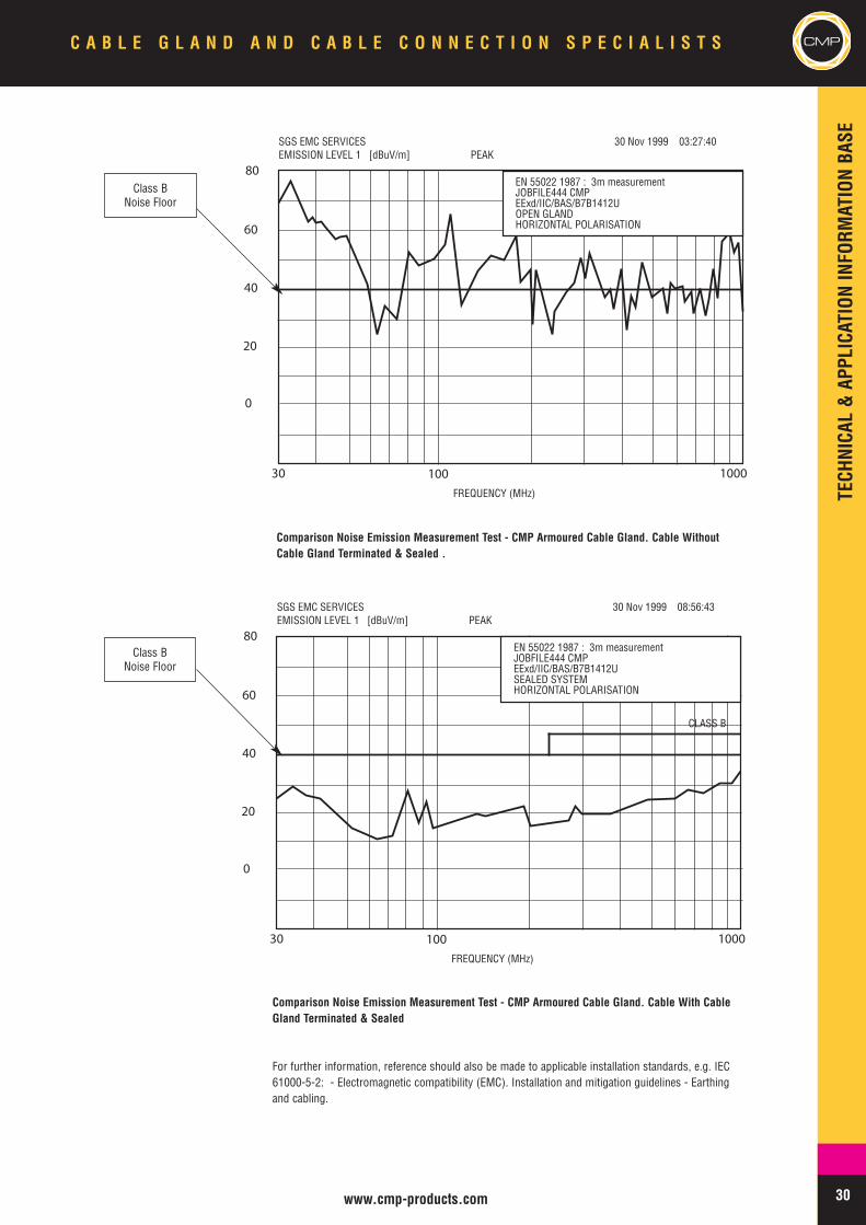
30www.cmp-products.com
FREQUENCY (MHz)
SGS EMC SERVICES 30 Nov 1999 03:27:40EMISSION LEVEL 1 [dBuV/m] PEAK
80
60
40
0
20
30 100 1000
EN 55022 1987 : 3m measurementJOBFILE444 CMPEExd/IIC/BAS/B7B1412UOPEN GLANDHORIZONTAL POLARISATION
Comparison Noise Emission Measurement Test - CMP Armoured Cable Gland. Cable WithoutCable Gland Terminated & Sealed .
FREQUENCY (MHz)
SGS EMC SERVICES 30 Nov 1999 08:56:43EMISSION LEVEL 1 [dBuV/m] PEAK
80
60
40
0
20
30 100 1000
EN 55022 1987 : 3m measurementJOBFILE444 CMPEExd/IIC/BAS/B7B1412USEALED SYSTEMHORIZONTAL POLARISATION
CLASS B
Comparison Noise Emission Measurement Test - CMP Armoured Cable Gland. Cable With CableGland Terminated & Sealed
For further information, reference should also be made to applicable installation standards, e.g. IEC61000-5-2: - Electromagnetic compatibility (EMC). Installation and mitigation guidelines - Earthingand cabling.
Class BNoise Floor
Class BNoise Floor
C A B L E G L A N D A N D C A B L E C O N N E C T I O N S P E C I A L I S T S CMP
TECHNICAL&APPLICATIONINFORM
ATIONBASE
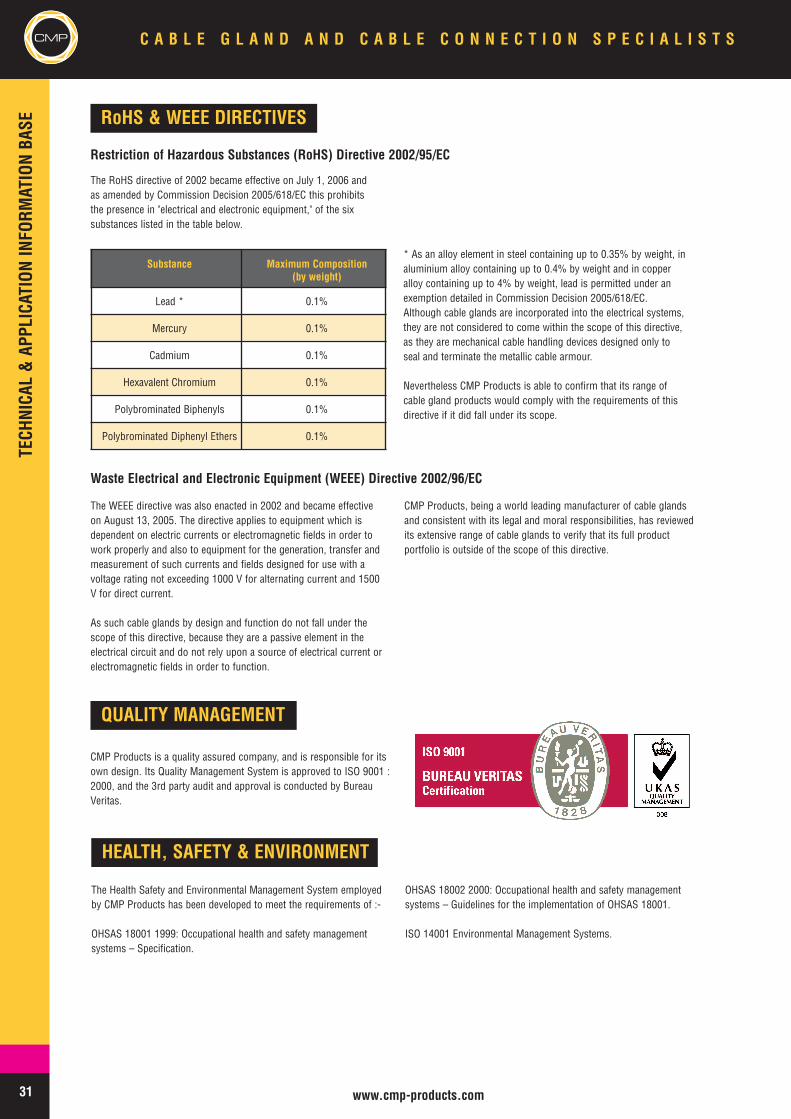
31 www.cmp-products.com
CMP C A B L E G L A N D A N D C A B L E C O N N E C T I O N S P E C I A L I S T S
HEALTH, SAFETY & ENVIRONMENT
The Health Safety and Environmental Management System employedby CMP Products has been developed to meet the requirements of :-
OHSAS 18001 1999: Occupational health and safety managementsystems – Specification.
OHSAS 18002 2000: Occupational health and safety managementsystems – Guidelines for the implementation of OHSAS 18001.
ISO 14001 Environmental Management Systems.
RoHS & WEEE DIRECTIVES
The RoHS directive of 2002 became effective on July 1, 2006 andas amended by Commission Decision 2005/618/EC this prohibitsthe presence in "electrical and electronic equipment," of the sixsubstances listed in the table below.
* As an alloy element in steel containing up to 0.35% by weight, inaluminium alloy containing up to 0.4% by weight and in copperalloy containing up to 4% by weight, lead is permitted under anexemption detailed in Commission Decision 2005/618/EC.Although cable glands are incorporated into the electrical systems,they are not considered to come within the scope of this directive,as they are mechanical cable handling devices designed only toseal and terminate the metallic cable armour.
Nevertheless CMP Products is able to confirm that its range ofcable gland products would comply with the requirements of thisdirective if it did fall under its scope.
Restriction of Hazardous Substances (RoHS) Directive 2002/95/EC
Waste Electrical and Electronic Equipment (WEEE) Directive 2002/96/EC
Substance Maximum Composition(by weight)
Lead * 0.1%
Mercury 0.1%
Cadmium 0.1%
Hexavalent Chromium 0.1%
Polybrominated Biphenyls 0.1%
Polybrominated Diphenyl Ethers 0.1%
The WEEE directive was also enacted in 2002 and became effectiveon August 13, 2005. The directive applies to equipment which isdependent on electric currents or electromagnetic fields in order towork properly and also to equipment for the generation, transfer andmeasurement of such currents and fields designed for use with avoltage rating not exceeding 1000 V for alternating current and 1500V for direct current.
As such cable glands by design and function do not fall under thescope of this directive, because they are a passive element in theelectrical circuit and do not rely upon a source of electrical current orelectromagnetic fields in order to function.
CMP Products, being a world leading manufacturer of cable glandsand consistent with its legal and moral responsibilities, has reviewedits extensive range of cable glands to verify that its full productportfolio is outside of the scope of this directive.
QUALITY MANAGEMENT
CMP Products is a quality assured company, and is responsible for itsown design. Its Quality Management System is approved to ISO 9001 :2000, and the 3rd party audit and approval is conducted by BureauVeritas.
TECHNICAL&APPLICATIONINFORM
ATIONBASE
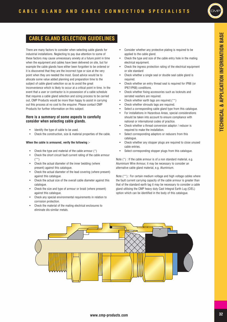
32www.cmp-products.com
CMPC A B L E G L A N D A N D C A B L E C O N N E C T I O N S P E C I A L I S T S
CABLE GLAND SELECTION GUIDELINES
There are many factors to consider when selecting cable glands forindustrial installations. Neglecting to pay due attention to some ofthese factors may cause unnecessary anxiety at a future point in timewhen the equipment and cables have been delivered on site, but forexample the cable glands have either been forgotten to be ordered orit is discovered that they are the incorrect type or size at the verypoint when they are needed the most. Good advice would be toallocate some value added planning and preparation time to thesubject of cable gland selection so as to avoid the greatinconvenience which is likely to occur at a critical point in time. In theevent that a user or contractor is in possession of a cable schedulethat requires a cable gland selection and sizing process to be carriedout, CMP Products would be more than happy to assist in carryingout this process at no cost to the enquirer. Please contact CMPProducts for further information on this subject.
Here is a summary of some aspects to carefullyconsider when selecting cable glands.
• Identify the type of cable to be used.• Check the construction, size & material properties of the cable.
When the cable is armoured, verify the following :-
• Check the type and material of the cable armour (*)• Check the short circuit fault current rating of the cable armour
(**)• Check the actual diameter of the inner bedding (where
present) against this catalogue.• Check the actual diameter of the lead covering (where present)
against this catalogue.• Check the actual size of the overall cable diameter against this
catalogue.• Check the size and type of armour or braid (where present)
against this catalogue.• Check any special environmental requirements in relation to
corrosion protection.• Check the material of the mating electrical enclosures to
eliminate dis-similar metals.
• Consider whether any protective plating is required to beapplied to the cable gland.
• Check the type and size of the cable entry hole in the matingelectrical equipment.
• Check the ingress protection rating of the electrical equipmentor site standard
• Check whether a single seal or double seal cable gland isrequired.
• Check whether an entry thread seal is required for IP66 (orIP67/IP68) conditions.
• Check whether fixing accessories such as locknuts andserrated washers are required.
• Check whether earth tags are required.(**)• Check whether shrouds tags are required.• Select a corresponding cable gland type from this catalogue.• For installations in Hazardous Areas, special considerations
should be taken into account to ensure compliance withnational or international codes of practice.
• Check whether a thread conversion adaptor / reducer isrequired to make the installation.
• Select corresponding adaptors or reducers from thiscatalogue.
• Check whether any stopper plugs are required to close unusedcable entries.
• Select corresponding stopper plugs from this catalogue.
Note (*) : If the cable armour is of a non standard material, e.g.Aluminium Wire Armour, it may be necessary to consider analternative cable gland material, e.g. Aluminium.
Note (**) : For certain medium voltage and high voltage cables wherethe fault current carrying capacity of the cable armour is greater thanthat of the standard earth tag it may be necessary to consider a cablegland utilising the CMP heavy duty Cast Integral Earth Lug (CIEL)option which can be identified in the body of this catalogue.
TECHNICAL&APPLICATIONINFORM
ATIONBASE
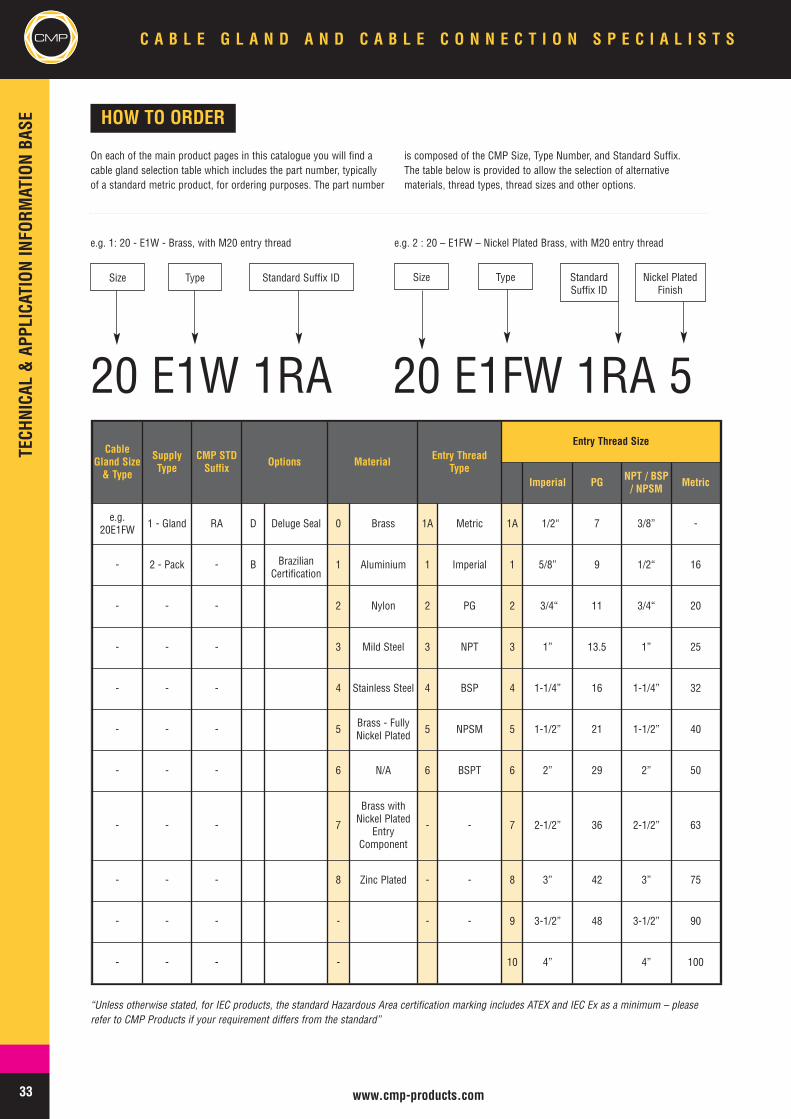
33 www.cmp-products.com
CMP C A B L E G L A N D A N D C A B L E C O N N E C T I O N S P E C I A L I S T S
HOW TO ORDER
On each of the main product pages in this catalogue you will find acable gland selection table which includes the part number, typicallyof a standard metric product, for ordering purposes. The part number
is composed of the CMP Size, Type Number, and Standard Suffix.The table below is provided to allow the selection of alternativematerials, thread types, thread sizes and other options.
e.g. 1: 20 - E1W - Brass, with M20 entry thread e.g. 2 : 20 – E1FW – Nickel Plated Brass, with M20 entry thread
20 E1W 1RA 20 E1FW 1RA 5
Size Type Standard Suffix ID Nickel PlatedFinish
Size Type StandardSuffix ID
CableGland Size& Type
SupplyType
CMP STDSuffix Options Material Entry Thread
Type
Entry Thread Size
Imperial PG NPT / BSP/ NPSM Metric
e.g.20E1FW 1 - Gland RA D Deluge Seal 0 Brass 1A Metric 1A 1/2“ 7 3/8” -
- 2 - Pack - B BrazilianCertification
1 Aluminium 1 Imperial 1 5/8” 9 1/2“ 16
- - - 2 Nylon 2 PG 2 3/4“ 11 3/4“ 20
- - - 3 Mild Steel 3 NPT 3 1” 13.5 1” 25
- - - 4 Stainless Steel 4 BSP 4 1-1/4” 16 1-1/4” 32
- - - 5 Brass - FullyNickel Plated 5 NPSM 5 1-1/2” 21 1-1/2” 40
- - - 6 N/A 6 BSPT 6 2” 29 2” 50
- - - 7
Brass withNickel Plated
EntryComponent
- - 7 2-1/2” 36 2-1/2” 63
- - - 8 Zinc Plated - - 8 3” 42 3” 75
- - - - - - 9 3-1/2” 48 3-1/2” 90
- - - - 10 4” 4” 100
“Unless otherwise stated, for IEC products, the standard Hazardous Area certification marking includes ATEX and IEC Ex as a minimum – pleaserefer to CMP Products if your requirement differs from the standard”
TECHNICAL&APPLICATIONINFORM
ATIONBASE
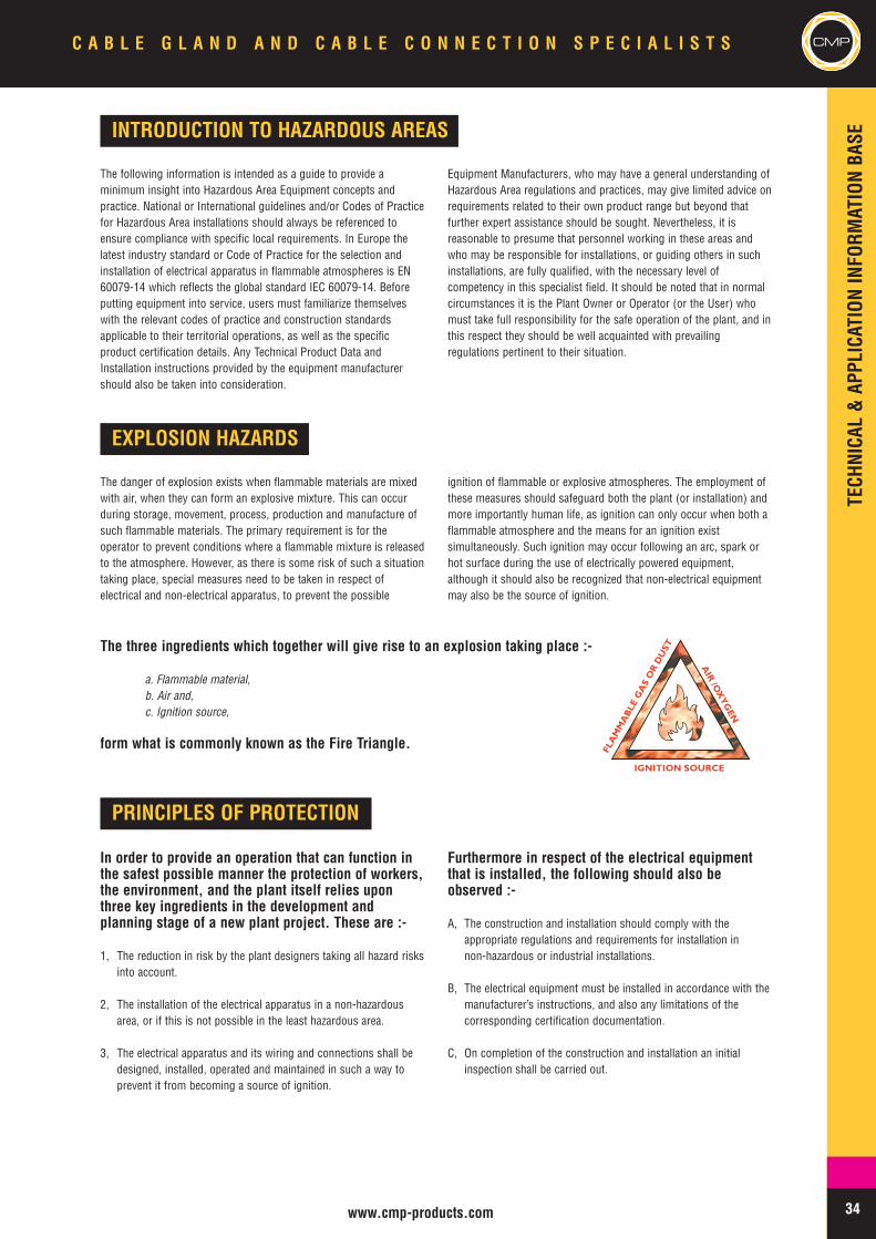
34www.cmp-products.com
CMPC A B L E G L A N D A N D C A B L E C O N N E C T I O N S P E C I A L I S T S
INTRODUCTION TO HAZARDOUS AREAS
The following information is intended as a guide to provide aminimum insight into Hazardous Area Equipment concepts andpractice. National or International guidelines and/or Codes of Practicefor Hazardous Area installations should always be referenced toensure compliance with specific local requirements. In Europe thelatest industry standard or Code of Practice for the selection andinstallation of electrical apparatus in flammable atmospheres is EN60079-14 which reflects the global standard IEC 60079-14. Beforeputting equipment into service, users must familiarize themselveswith the relevant codes of practice and construction standardsapplicable to their territorial operations, as well as the specificproduct certification details. Any Technical Product Data andInstallation instructions provided by the equipment manufacturershould also be taken into consideration.
Equipment Manufacturers, who may have a general understanding ofHazardous Area regulations and practices, may give limited advice onrequirements related to their own product range but beyond thatfurther expert assistance should be sought. Nevertheless, it isreasonable to presume that personnel working in these areas andwho may be responsible for installations, or guiding others in suchinstallations, are fully qualified, with the necessary level ofcompetency in this specialist field. It should be noted that in normalcircumstances it is the Plant Owner or Operator (or the User) whomust take full responsibility for the safe operation of the plant, and inthis respect they should be well acquainted with prevailingregulations pertinent to their situation.
EXPLOSION HAZARDS
The danger of explosion exists when flammable materials are mixedwith air, when they can form an explosive mixture. This can occurduring storage, movement, process, production and manufacture ofsuch flammable materials. The primary requirement is for theoperator to prevent conditions where a flammable mixture is releasedto the atmosphere. However, as there is some risk of such a situationtaking place, special measures need to be taken in respect ofelectrical and non-electrical apparatus, to prevent the possible
ignition of flammable or explosive atmospheres. The employment ofthese measures should safeguard both the plant (or installation) andmore importantly human life, as ignition can only occur when both aflammable atmosphere and the means for an ignition existsimultaneously. Such ignition may occur following an arc, spark orhot surface during the use of electrically powered equipment,although it should also be recognized that non-electrical equipmentmay also be the source of ignition.
The three ingredients which together will give rise to an explosion taking place :-
a. Flammable material,b. Air and,c. Ignition source,
form what is commonly known as the Fire Triangle.
PRINCIPLES OF PROTECTION
In order to provide an operation that can function inthe safest possible manner the protection of workers,the environment, and the plant itself relies uponthree key ingredients in the development andplanning stage of a new plant project. These are :-
1, The reduction in risk by the plant designers taking all hazard risksinto account.
2, The installation of the electrical apparatus in a non-hazardousarea, or if this is not possible in the least hazardous area.
3, The electrical apparatus and its wiring and connections shall bedesigned, installed, operated and maintained in such a way toprevent it from becoming a source of ignition.
Furthermore in respect of the electrical equipmentthat is installed, the following should also beobserved :-
A, The construction and installation should comply with theappropriate regulations and requirements for installation innon-hazardous or industrial installations.
B, The electrical equipment must be installed in accordance with themanufacturer’s instructions, and also any limitations of thecorresponding certification documentation.
C, On completion of the construction and installation an initialinspection shall be carried out.
TECHNICAL&APPLICATIONINFORM
ATIONBASE
AIR
/OX
YG
EN
IGNITION SOURCE
FLA
MM
AB
LEG
AS
OR
DU
ST
35 www.cmp-products.com
CMP C A B L E G L A N D A N D C A B L E C O N N E C T I O N S P E C I A L I S T S
RISK ASSESSMENT PROCESS FOR HAZARDOUS AREAS
In addressing the factors of risk in the hazardous area a process ofRisk Assessment and Risk Control should be undertaken to ensure asafe working environment. This process will involve identifying whoand what is likely to be at risk of harm, and will include an evaluationof these risks. Part of the process will entail identification of thehazards involved, the possible sources of release of flammablematerials, the grades of release, the potential ignition sources, andwhat measure may be taken by design or other means to minimise oreliminate risks. Findings and conclusions from the Risk Assessmentshould be documented for subsequent examination, and theassessment process should be reviewed periodically and revised ifnecessary. Existing precautions and contingencies that are already inplace should be reviewed to verify whether they are adequate, or iffurther risk prevention measures need to be implemented.
In addressing the factors of risk in the hazardous area a process ofRisk Assessment and Risk Control should be undertaken to ensure asafe working environment. This process will involve identifying whoand what is likely to be at risk of harm, and will include an evaluationof these risks. Part of the process will entail identification of thehazards involved, the possible sources of release of flammablematerials, the grades of release, the potential ignition sources, andwhat measure may be taken by design or other means to minimise oreliminate risks. Findings and conclusions from the Risk Assessmentshould be documented for subsequent examination, and theassessment process should be reviewed periodically and revised ifnecessary. Existing precautions and contingencies that are already inplace should be reviewed to verify whether they are adequate, or iffurther risk prevention measures need to be implemented.
SOURCES OF RELEASE
Sources of release may originate from almost anywhere in theprocess or storage area of a hazardous area site. Flammablematerials may be released from Pumps, Pipes, Flanges, Valves,
Sampling Points, or other similar apparatus. The release may becaused for example by either seal failure at joints to flanges, rupturesto pipe work, or inadvertent operations error.
GRADES OF RELEASE
Factors taken into account during the Area Classification processinclude Grades of Release which are defined as follows :-
Continuous – a release which is either continuous or is expected tooccur for long periods.
Primary – a release which can be expected to occur periodically oroccasionally during normal operation.
Secondary – a release which is not expected to occur in normaloperation and if it does occur it is likely to do so infrequently and forshort periods.
FLAMMABLE MATERIAL PROPERTIES
A flammable mixture can be classified for explosion protection underseveral key characteristics including its Relative Density, Flash Point,Flammable Limits, Ignition Energy and Ignition Temperature. In orderto ensure correct assessment in terms of risk and correct selection ofapparatus to be used in the hazardous areas, it is important tounderstand all of the particulars of the flammable materials beinghandled in any process plant. For example, it may be vital to know the
temperature of ignition by hot surfaces, the flash point, or the lowerexplosive limit of the flammable mixture that a particular process willbecome exposed to before accurate and proper risk assessments canbe made. The data relating to the particulars of a given substance maybe extracted from recognised standards that define the characteristicsof the most commonly handled or known substances. The definitionsof the main characteristics are shown below.
Relative Density : The density of a gas or a vapour relative to thedensity of air. The result would be displayed in reference to air havinga value equal to 1.
Flash Point : The minimum temperature at which a liquid give offsufficient vapour to form an explosive atmosphere when tested in aset of standard test apparatus.
Flammable Limits : The upper and lower percentages of gas / airmixture at normal atmospheric temperature and pressure which willburn if ignited.
TECHNICAL&APPLICATIONINFORM
ATIONBASE
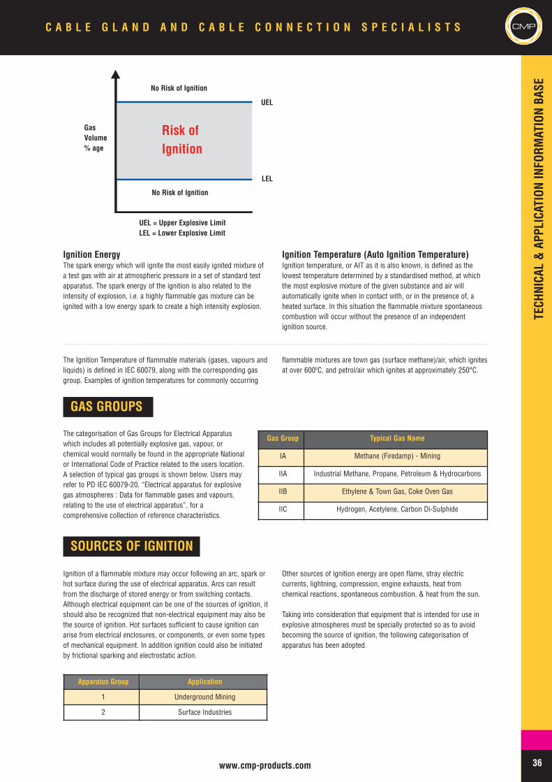
36www.cmp-products.com
CMPC A B L E G L A N D A N D C A B L E C O N N E C T I O N S P E C I A L I S T S
Ignition EnergyThe spark energy which will ignite the most easily ignited mixture ofa test gas with air at atmospheric pressure in a set of standard testapparatus. The spark energy of the ignition is also related to theintensity of explosion, i.e. a highly flammable gas mixture can beignited with a low energy spark to create a high intensity explosion.
Ignition Temperature (Auto Ignition Temperature)Ignition temperature, or AIT as it is also known, is defined as thelowest temperature determined by a standardised method, at whichthe most explosive mixture of the given substance and air willautomatically ignite when in contact with, or in the presence of, aheated surface. In this situation the flammable mixture spontaneouscombustion will occur without the presence of an independentignition source.
GAS GROUPS
The categorisation of Gas Groups for Electrical Apparatuswhich includes all potentially explosive gas, vapour, orchemical would normally be found in the appropriate Nationalor International Code of Practice related to the users location.A selection of typical gas groups is shown below. Users mayrefer to PD IEC 60079-20, “Electrical apparatus for explosivegas atmospheres : Data for flammable gases and vapours,relating to the use of electrical apparatus”, for acomprehensive collection of reference characteristics.
Gas Group Typical Gas Name
IA Methane (Firedamp) - Mining
IIA Industrial Methane, Propane, Petroleum & Hydrocarbons
IIB Ethylene & Town Gas, Coke Oven Gas
IIC Hydrogen, Acetylene, Carbon Di-Sulphide
SOURCES OF IGNITION
Ignition of a flammable mixture may occur following an arc, spark orhot surface during the use of electrical apparatus. Arcs can resultfrom the discharge of stored energy or from switching contacts.Although electrical equipment can be one of the sources of ignition, itshould also be recognized that non-electrical equipment may also bethe source of ignition. Hot surfaces sufficient to cause ignition canarise from electrical enclosures, or components, or even some typesof mechanical equipment. In addition ignition could also be initiatedby frictional sparking and electrostatic action.
Other sources of ignition energy are open flame, stray electriccurrents, lightning, compression, engine exhausts, heat fromchemical reactions, spontaneous combustion, & heat from the sun.
Taking into consideration that equipment that is intended for use inexplosive atmospheres must be specially protected so as to avoidbecoming the source of ignition, the following categorisation ofapparatus has been adopted.
The Ignition Temperature of flammable materials (gases, vapours andliquids) is defined in IEC 60079, along with the corresponding gasgroup. Examples of ignition temperatures for commonly occurring
flammable mixtures are town gas (surface methane)/air, which ignitesat over 600ºC, and petrol/air which ignites at approximately 250°C.
Apparatus Group Application
1 Underground Mining
2 Surface Industries
UEL = Upper Explosive LimitLEL = Lower Explosive Limit
Risk ofIgnition
No Risk of Ignition
GasVolume% age
UEL
LEL
No Risk of Ignition
TECHNICAL&APPLICATIONINFORM
ATIONBASE
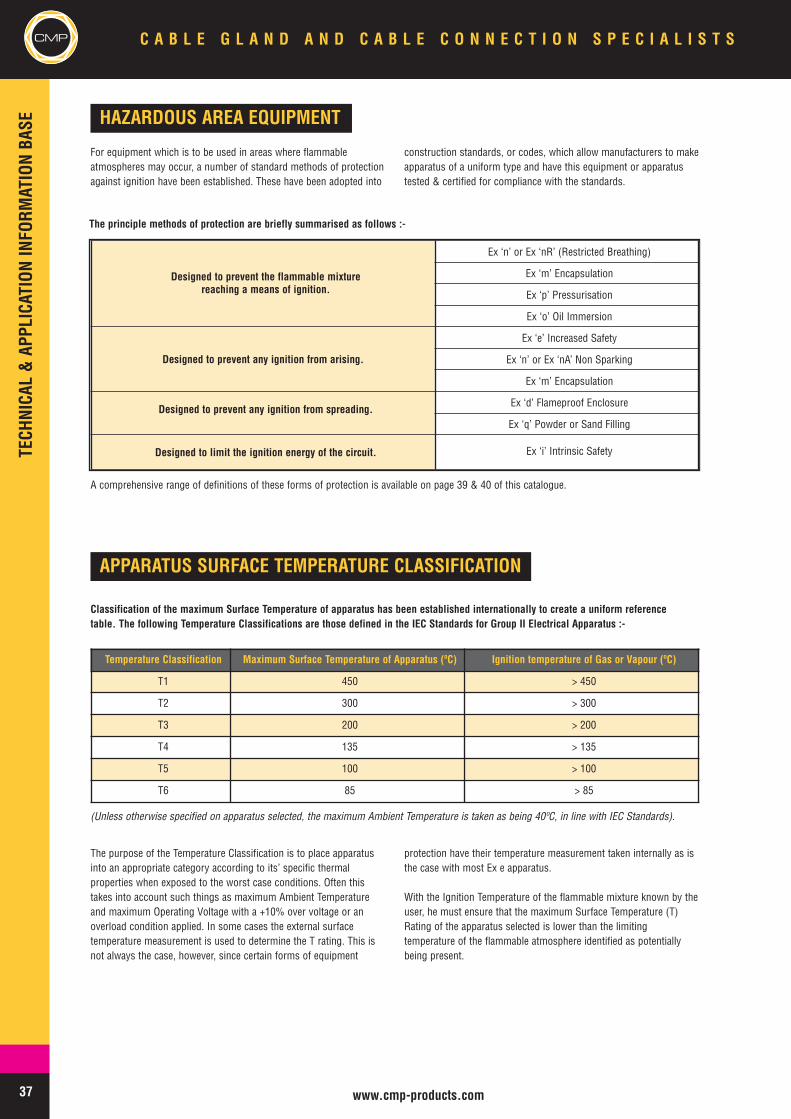
37 www.cmp-products.com
CMP C A B L E G L A N D A N D C A B L E C O N N E C T I O N S P E C I A L I S T S
HAZARDOUS AREA EQUIPMENT
The principle methods of protection are briefly summarised as follows :-
For equipment which is to be used in areas where flammableatmospheres may occur, a number of standard methods of protectionagainst ignition have been established. These have been adopted into
construction standards, or codes, which allow manufacturers to makeapparatus of a uniform type and have this equipment or apparatustested & certified for compliance with the standards.
Designed to prevent the flammable mixturereaching a means of ignition.
Ex ‘n’ or Ex ‘nR’ (Restricted Breathing)
Ex ‘m’ Encapsulation
Ex ‘p’ Pressurisation
Ex ‘o’ Oil Immersion
Designed to prevent any ignition from arising.
Ex ‘e’ Increased Safety
Ex ‘n’ or Ex ‘nA’ Non Sparking
Ex ‘m’ Encapsulation
Designed to prevent any ignition from spreading.Ex ‘d’ Flameproof Enclosure
Ex ‘q’ Powder or Sand Filling
Designed to limit the ignition energy of the circuit. Ex ‘i’ Intrinsic Safety
APPARATUS SURFACE TEMPERATURE CLASSIFICATION
Classification of the maximum Surface Temperature of apparatus has been established internationally to create a uniform referencetable. The following Temperature Classifications are those defined in the IEC Standards for Group II Electrical Apparatus :-
Temperature Classification Maximum Surface Temperature of Apparatus (ºC) Ignition temperature of Gas or Vapour (ºC)
T1 450 > 450
T2 300 > 300
T3 200 > 200
T4 135 > 135
T5 100 > 100
T6 85 > 85
(Unless otherwise specified on apparatus selected, the maximum Ambient Temperature is taken as being 40ºC, in line with IEC Standards).
The purpose of the Temperature Classification is to place apparatusinto an appropriate category according to its’ specific thermalproperties when exposed to the worst case conditions. Often thistakes into account such things as maximum Ambient Temperatureand maximum Operating Voltage with a +10% over voltage or anoverload condition applied. In some cases the external surfacetemperature measurement is used to determine the T rating. This isnot always the case, however, since certain forms of equipment
protection have their temperature measurement taken internally as isthe case with most Ex e apparatus.
With the Ignition Temperature of the flammable mixture known by theuser, he must ensure that the maximum Surface Temperature (T)Rating of the apparatus selected is lower than the limitingtemperature of the flammable atmosphere identified as potentiallybeing present.
TECHNICAL&APPLICATIONINFORM
ATIONBASE
A comprehensive range of definitions of these forms of protection is available on page 39 & 40 of this catalogue.
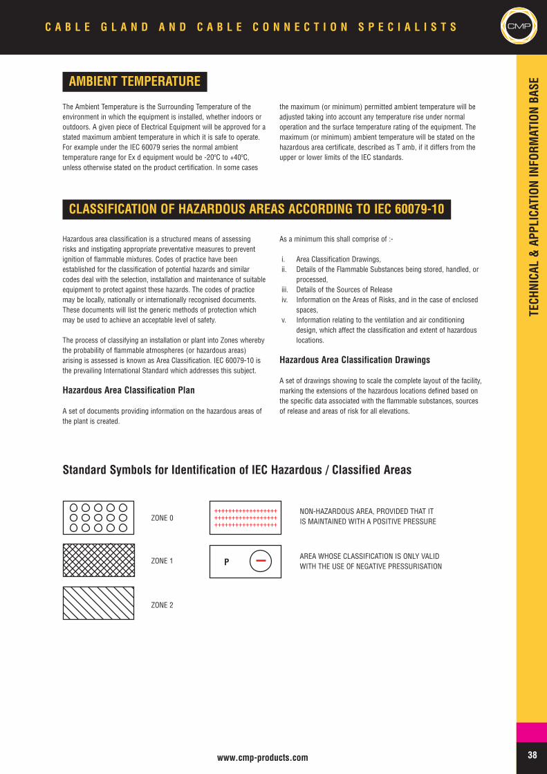
++++++++++++++++++++++++++++++++++++++++++++++++++++++
P
38www.cmp-products.com
CMPC A B L E G L A N D A N D C A B L E C O N N E C T I O N S P E C I A L I S T S
AMBIENT TEMPERATURE
The Ambient Temperature is the Surrounding Temperature of theenvironment in which the equipment is installed, whether indoors oroutdoors. A given piece of Electrical Equipment will be approved for astated maximum ambient temperature in which it is safe to operate.For example under the IEC 60079 series the normal ambienttemperature range for Ex d equipment would be -20ºC to +40ºC,unless otherwise stated on the product certification. In some cases
the maximum (or minimum) permitted ambient temperature will beadjusted taking into account any temperature rise under normaloperation and the surface temperature rating of the equipment. Themaximum (or minimum) ambient temperature will be stated on thehazardous area certificate, described as T amb, if it differs from theupper or lower limits of the IEC standards.
CLASSIFICATION OF HAZARDOUS AREAS ACCORDING TO IEC 60079-10
Hazardous area classification is a structured means of assessingrisks and instigating appropriate preventative measures to preventignition of flammable mixtures. Codes of practice have beenestablished for the classification of potential hazards and similarcodes deal with the selection, installation and maintenance of suitableequipment to protect against these hazards. The codes of practicemay be locally, nationally or internationally recognised documents.These documents will list the generic methods of protection whichmay be used to achieve an acceptable level of safety.
The process of classifying an installation or plant into Zones wherebythe probability of flammable atmospheres (or hazardous areas)arising is assessed is known as Area Classification. IEC 60079-10 isthe prevailing International Standard which addresses this subject.
Hazardous Area Classification Plan
A set of documents providing information on the hazardous areas ofthe plant is created.
As a minimum this shall comprise of :-
i. Area Classification Drawings,ii. Details of the Flammable Substances being stored, handled, or
processed,iii. Details of the Sources of Releaseiv. Information on the Areas of Risks, and in the case of enclosed
spaces,v. Information relating to the ventilation and air conditioning
design, which affect the classification and extent of hazardouslocations.
Hazardous Area Classification Drawings
A set of drawings showing to scale the complete layout of the facility,marking the extensions of the hazardous locations defined based onthe specific data associated with the flammable substances, sourcesof release and areas of risk for all elevations.
Standard Symbols for Identification of IEC Hazardous / Classified Areas
ZONE 0
ZONE 1
ZONE 2
NON-HAZARDOUS AREA, PROVIDED THAT ITIS MAINTAINED WITH A POSITIVE PRESSURE
AREA WHOSE CLASSIFICATION IS ONLY VALIDWITH THE USE OF NEGATIVE PRESSURISATION
TECHNICAL&APPLICATIONINFORM
ATIONBASE
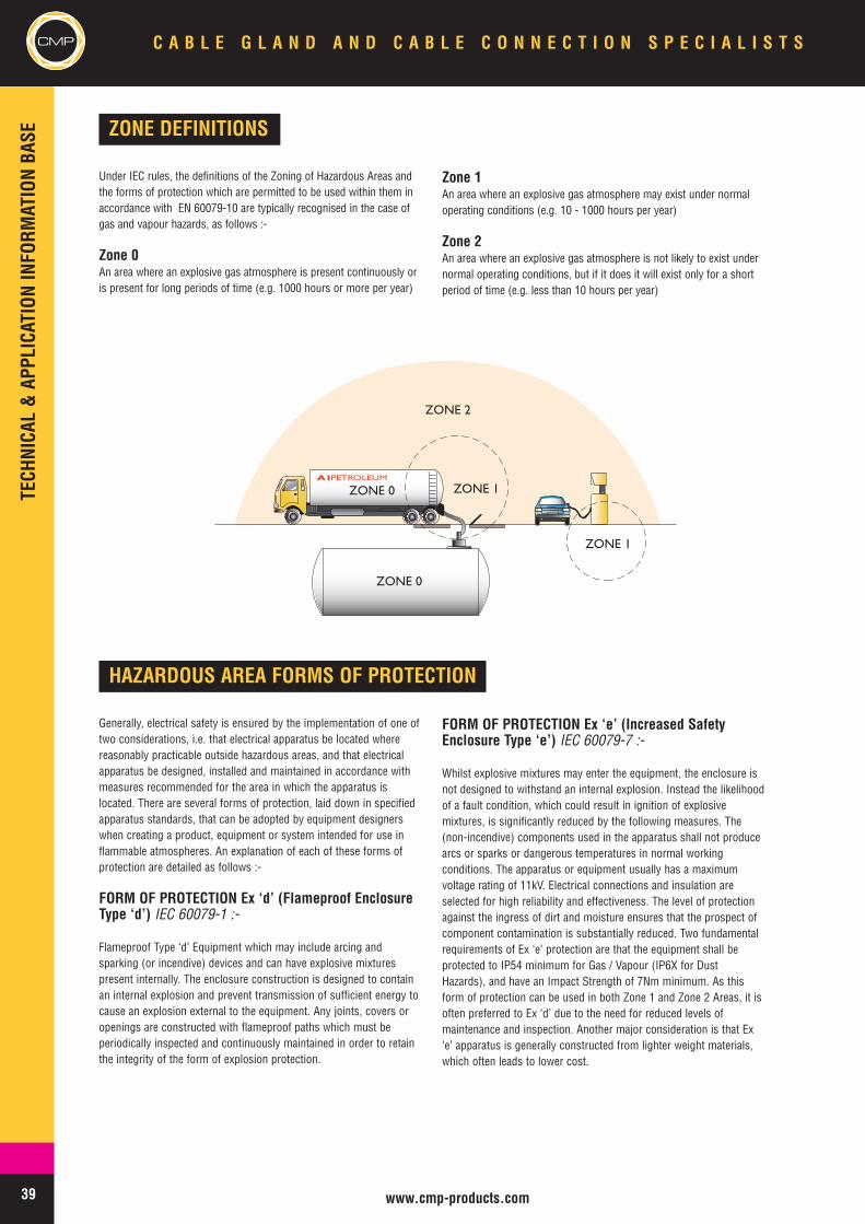
39 www.cmp-products.com
CMP C A B L E G L A N D A N D C A B L E C O N N E C T I O N S P E C I A L I S T S
ZONE DEFINITIONS
Under IEC rules, the definitions of the Zoning of Hazardous Areas andthe forms of protection which are permitted to be used within them inaccordance with EN 60079-10 are typically recognised in the case ofgas and vapour hazards, as follows :-
Zone 0An area where an explosive gas atmosphere is present continuously oris present for long periods of time (e.g. 1000 hours or more per year)
Zone 1An area where an explosive gas atmosphere may exist under normaloperating conditions (e.g. 10 - 1000 hours per year)
Zone 2An area where an explosive gas atmosphere is not likely to exist undernormal operating conditions, but if it does it will exist only for a shortperiod of time (e.g. less than 10 hours per year)
ZONE 1
A1PETROLEUM
ZONE 1
ZONE 0
ZONE 0
ZONE 2
HAZARDOUS AREA FORMS OF PROTECTION
Generally, electrical safety is ensured by the implementation of one oftwo considerations, i.e. that electrical apparatus be located wherereasonably practicable outside hazardous areas, and that electricalapparatus be designed, installed and maintained in accordance withmeasures recommended for the area in which the apparatus islocated. There are several forms of protection, laid down in specifiedapparatus standards, that can be adopted by equipment designerswhen creating a product, equipment or system intended for use inflammable atmospheres. An explanation of each of these forms ofprotection are detailed as follows :-
FORM OF PROTECTION Ex ‘d’ (Flameproof EnclosureType ‘d’) IEC 60079-1 :-
Flameproof Type ‘d’ Equipment which may include arcing andsparking (or incendive) devices and can have explosive mixturespresent internally. The enclosure construction is designed to containan internal explosion and prevent transmission of sufficient energy tocause an explosion external to the equipment. Any joints, covers oropenings are constructed with flameproof paths which must beperiodically inspected and continuously maintained in order to retainthe integrity of the form of explosion protection.
FORM OF PROTECTION Ex ‘e’ (Increased SafetyEnclosure Type ‘e’) IEC 60079-7 :-
Whilst explosive mixtures may enter the equipment, the enclosure isnot designed to withstand an internal explosion. Instead the likelihoodof a fault condition, which could result in ignition of explosivemixtures, is significantly reduced by the following measures. The(non-incendive) components used in the apparatus shall not producearcs or sparks or dangerous temperatures in normal workingconditions. The apparatus or equipment usually has a maximumvoltage rating of 11kV. Electrical connections and insulation areselected for high reliability and effectiveness. The level of protectionagainst the ingress of dirt and moisture ensures that the prospect ofcomponent contamination is substantially reduced. Two fundamentalrequirements of Ex ‘e’ protection are that the equipment shall beprotected to IP54 minimum for Gas / Vapour (IP6X for DustHazards), and have an Impact Strength of 7Nm minimum. As thisform of protection can be used in both Zone 1 and Zone 2 Areas, it isoften preferred to Ex ‘d’ due to the need for reduced levels ofmaintenance and inspection. Another major consideration is that Ex‘e’ apparatus is generally constructed from lighter weight materials,which often leads to lower cost.
TECHNICAL&APPLICATIONINFORM
ATIONBASE
40www.cmp-products.com
CMPC A B L E G L A N D A N D C A B L E C O N N E C T I O N S P E C I A L I S T S
FORM OF PROTECTION Ex ‘de’IEC 60079-1 & – IEC 60079-7 :-
Primary Flameproof Type ‘d’ Enclosure with Secondary IncreasedSafety Type ‘e’ Protection, allowing reduced frequency of periodicmaintenance and inspection cycle because of the ‘e’ philosophystrategically employed. In the case of Flameproof Type ‘d’ Enclosureshaving an Increased Safety Type ‘e’ Terminal Chamber, ‘line barriers’would normally be utilised between the Type ‘d’ and Type ‘e’compartments creating an indirect cable entry interface.Consequently this would permit the use of Cable Glands withIncreased Safety Type ‘e’ form of protection.
NOTE : Other forms of primary and secondary protection methodsexist. This example has been included to demonstrate a commonlyused application of the concept.
CODE OF PROTECTION Ex ‘ i ’IEC 60079-11 :-
Intrinsically Safe Apparatus (Sub grouped into Ex ia and Ex ib) ofthese types incorporate circuits which due to their low spark energypotential are not capable of igniting an explosive mixture. Ex ibequipment is safe under one fault condition and can be used in Zone1 Areas. Ex ia equipment is safe under two fault conditions and canbe used in Zone 0 Areas. The Intrinsically Safe components orcircuitry may be housed in an enclosure having another form ofprotection e.g. Ex e or Ex d, although the enclosure need not alwaysbe an approved item in its own right. In all cases it is important thatthe integrity of the housing or enclosure is maintained in accordancewith the form of protection pertaining to it.
CODE OF PROTECTION Ex ‘m’IEC 60079-5 :-
Encapsulation of arcing and sparking components or apparatus in afashion which ensures that there is no exposure to explosivemixtures which may be present, and the surface temperature iscontrolled under normal and fault conditions, thus preventing ignitionfrom occurring.
CODE OF PROTECTION Ex ‘n’EN 60079-15 :-
Permitted only in areas where the likelihood of a flammableatmosphere is remote (Zone 2),Non incendive Type ‘n’ Apparatus isdivided into four sub-forms as follows :-
Non-Sparking – Ex nA – Components selected for non arcing orsparking.Enclosed Break – Ex nC – Incendive components, e.g. lampholders,enclosed and sealed to exclude gas or vapour from reaching ignitioncapable components.Energy Limitation – Ex nL – Low energy circuitry eliminates potentialfor ignition.Restricted Breathing – Ex nR – Relies upon the sealing and gasketingof the apparatus to ensure that the flammable mixture is kept awayfrom any hot surfaces and ignition capable components so that itdoes not enter the enclosure in sufficient quantity to reach thespecific L.E.L. documented.
Apparatus with the type ‘n’ protection method is considered to benon incendive in that it does not usually generate arcs or sparks ordangerous temperatures in normal service. Internal componenttemperatures must be controlled and wiring connections andterminals selected with ‘Non-sparking’ in mind. The concept sharessimilarities with the Ex e philosophy but is suitable only for use inZone 2 (or 22 where the apparatus may also be approved for dusthazards). This apparatus type is not designed to withstand explosion,and would usually employ a light weight enclosure of metallic or nonmetallic construction, but one that ensures a high Ingress Protectionlevel is maintained.
In cases where the internal surface temperatures of componentscannot be controlled in line with prescribed T ratings, the RestrictedBreathing method (Ex nR) is adopted whereby joints and covers havetightly fitted seals and gaskets to provide the additional protection.This effectively excludes any external explosive mixtures which maybe present from entering the enclosure and reaching the hotcomponents. The ‘Restricted Breathing Enclosure’ technique istypically used in the design and construction of certain types ofLighting Equipment for Zone 2 Areas where the operatingtemperature of the lamp would otherwise be dangerously high. Withthis form of protection the user is responsible for ensuring that thecable entry device (Cable Gland) provides an adequate gas tight sealand maintains the integrity of the equipment protection code asdetailed under the applicable standard to which it was tested andcertified.
CODE OF PROTECTION Ex ‘o’EN 60079-18 :-
Permitted only in areas where the likelihood of a flammableatmosphere is remote (Zone 2),Type ‘o’ Apparatus where the sparkingcomponents are immersed in Oil and controlled venting is also afeature, for example in early forms of switch gear.
CODE OF PROTECTION Ex ‘p’EN 60079-2 :-
Pressurised or purged Apparatus Type ‘p’ rely on a combination of apositive static pressure applied inside the enclosure and a continuousflow of air or inert gas to expel any explosive mixture which mayhave entered. The system relies essentially on purging schedules andmonitoring systems to ensure the reliability and effectiveness of theoverall protection.
CODE OF PROTECTION Ex ‘q’EN 60079-5 :-
Powder filled Enclosures Type ‘q’ which house arcing and sparking(or incendive) devices and include a vent. Often used to contain theenergy released from the failure of electrical or electroniccomponents such as the breaking of a fuse. This form of protection isoften associated with components inside Ex e apparatus for examplelighting control gear.
TECHNICAL&APPLICATIONINFORM
ATIONBASE

41 www.cmp-products.com
CMP C A B L E G L A N D A N D C A B L E C O N N E C T I O N S P E C I A L I S T S
COMBUSTIBLE DUST HAZARDS
IEC 61241-0 Electrical apparatus for use in the presence of combustible dust – general requirements.
IEC 61241-1 Electrical apparatus for use in the presence of combustible dust. Protection by enclosures "tD"
IEC 61241-4 Electrical apparatus for use in the presence of combustible dust. Type of Protection "pD"
IEC 61241-11 Electrical apparatus for use in the presence of combustible dust. Protection by intrinsic safety "iD"
IEC 61241-18 Electrical apparatus for use in the presence of combustible dust. Protection by encapsulation "mD"
IEC 61241 - Electrical apparatus for use in thepresence of combustible dust.
Many dusts that are generated, processed, handled and stored arecombustible. When ignited they can burn rapidly and withconsiderable explosive force if mixed with air in the appropriateproportions. When electrical apparatus is used in locations wherecombustible materials are present, it is important that suitableprecautions are taken. In electrical apparatus, potential ignitionsources include electrical arcs and sparks, hot surfaces and frictionalsparks. To reduce the likelihood of ignition of the external explosiveatmosphere, all such electrical apparatus should be adequatelyprotected.
Areas where dust, flyings and fibres in air occur in dangerousquantities are classified as hazardous and are divided into three zonesaccording to the level of risk.
Zone 20 An area in which combustible dust, as a cloud, is presentcontinuously or frequently, during normal operation, in
sufficient quantity to be capable of producing an explosiveconcentration of combustible dust in a mixture with air.
Zone 21 An area, in which combustible dust, as a cloud, isoccasionally present during normal operation, in a sufficient quantityto be capable of producing an explosive concentration of combustibledust in a mixture with air.
Zone 22 An area, in which combustible dust, as a cloud, may occurinfrequently and persist for only a short period, or in whichaccumulations of layers of combustible dust may give rise to anexplosive concentration of combustible dust in a mixture with air.
The standards and corresponding forms of protection that have beenestablished for dust hazard protection are detailed as follows :-
IEC 61241-0 Electrical apparatus for use in the presence of combustible dust. Classification of areas where combustible dusts are,or may be present.
IEC 61241-2-1 Electrical apparatus for use in the presence of combustible dust - Part 2: Test methods - Section 1: Methods fordetermining the minimum ignition temperatures of dust.
IEC 61241-2-2 Electrical apparatus for use in the presence of combustible dust - Part 2: Test methods - Section 2: Method fordetermining the electrical resistivity of dust in layers.
IEC 61241-2-3 Electrical apparatus for use in the presence of combustible dust - Part 2: Test methods - Section 3: Method fordetermining minimum ignition energy of dust/air mixtures.
The standard for classification of hazardous areas where dust are or may be present was previouslyIEC 61241-10, but is now recoded as follows :-
The standard test methods for determining the characteristics of the dust hazard are shown as follows :-
TECHNICAL&APPLICATIONINFORM
ATIONBASE

42www.cmp-products.com
CMPC A B L E G L A N D A N D C A B L E C O N N E C T I O N S P E C I A L I S T S
Combustible dust can be ignited by electricalapparatus in several ways :-
• By surfaces of the apparatus that are above the minimum ignitiontemperature of the dust concerned. The temperature at which atype of dust ignites is a function of the properties of the dust,whether the dust is in a cloud or layer, the thickness of the layerand the geometry of the heat source.
• By arcing or sparking of electrical parts such as switches,contacts, commutators, brushes, or the like.
• By discharge of an accumulated electrostatic charge.
• By radiated energy (e.g. electromagnetic radiation).
• By mechanical sparking or frictional sparking or heatingassociated with the apparatus.
Selection of Equipment for Dust Hazards :-
When selecting equipment intended for use in areas where potentiallyexplosive dust hazards may be present, and accessible to dust, theselection process would entail the review of certified equipment ratedfor dust hazards to a standard set of procedures. This would involveselection of the form of equipment protection, and ATEX dust groupwhen applicable, and also identifying the permissible IgnitionTemperature of the apparatus.
Dust in its deposited form has a different ignition temperature than inits stirred form.IEC 61241-2-1 specifies the method of determining the ignitiontemperatures identified as procedure A for deposits, or layers, andprocedure B for clouds.
The permissible Ignition Temperature of the apparatus would bedetermined by firstly identifying the ignition temperature of the dustas a deposit, and then as a cloud :-
Smouldering temperature based upon ‘Deposit’ – Method Aaccording to IEC 61241-2-1Ignition temperature based upon ‘Cloud’ – Method B according to IEC61241-2-1
Secondly by subtracting 75 K from the value determined usingmethod A and by multiplying by 2/3 the value determined usingmethod B, the two ignition temperature values for the combustibledust will be known. The lower of the two values determined in thisway corresponds to the lowest permissible surface temperature ofthe equipment.
For example the following results may be drawn forbrown coal :-
T max = Smouldering temperature -75 K e. g. brown coal 225 °C -75°C = 150 °C or,
T max = 2/3 of the ignition temperature e. g. brown coal 2/3 * 380 °C= 254 °C,
In which case equipment should be selected that is limited to a Tmax150 °C rating.
It should be noted that compliance with this standard will onlyprovide the required level of safety if the electrical apparatus isoperated within its rating and is installed and maintained according tothe relevant codes of practice or requirements, for example in respectof protection against over currents, internal short-circuits, and otherelectrical faults. In particular, it is essential that the severity andduration of an internal or external fault be limited to values that canbe sustained by the electrical apparatus without damage.
TECHNICAL&APPLICATIONINFORM
ATIONBASE
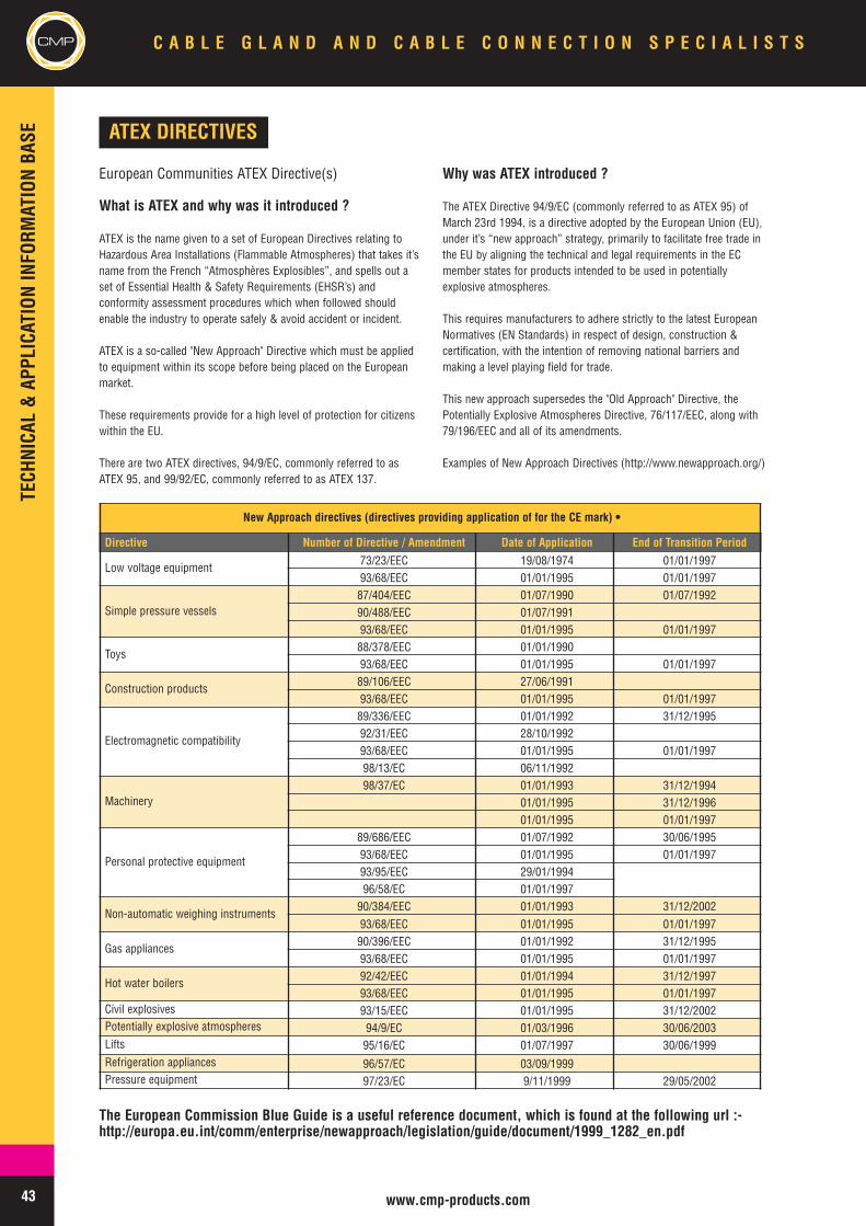
43 www.cmp-products.com
CMP C A B L E G L A N D A N D C A B L E C O N N E C T I O N S P E C I A L I S T S
The European Commission Blue Guide is a useful reference document, which is found at the following url :-http://europa.eu.int/comm/enterprise/newapproach/legislation/guide/document/1999_1282_en.pdf
ATEX DIRECTIVES
European Communities ATEX Directive(s)
What is ATEX and why was it introduced ?
ATEX is the name given to a set of European Directives relating toHazardous Area Installations (Flammable Atmospheres) that takes it’sname from the French “Atmosphères Explosibles”, and spells out aset of Essential Health & Safety Requirements (EHSR’s) andconformity assessment procedures which when followed shouldenable the industry to operate safely & avoid accident or incident.
ATEX is a so-called "New Approach" Directive which must be appliedto equipment within its scope before being placed on the Europeanmarket.
These requirements provide for a high level of protection for citizenswithin the EU.
There are two ATEX directives, 94/9/EC, commonly referred to asATEX 95, and 99/92/EC, commonly referred to as ATEX 137.
Why was ATEX introduced ?
The ATEX Directive 94/9/EC (commonly referred to as ATEX 95) ofMarch 23rd 1994, is a directive adopted by the European Union (EU),under it’s “new approach” strategy, primarily to facilitate free trade inthe EU by aligning the technical and legal requirements in the ECmember states for products intended to be used in potentiallyexplosive atmospheres.
This requires manufacturers to adhere strictly to the latest EuropeanNormatives (EN Standards) in respect of design, construction &certification, with the intention of removing national barriers andmaking a level playing field for trade.
This new approach supersedes the "Old Approach" Directive, thePotentially Explosive Atmospheres Directive, 76/117/EEC, along with79/196/EEC and all of its amendments.
Examples of New Approach Directives (http://www.newapproach.org/)
New Approach directives (directives providing application of for the CE mark) •
Directive Number of Directive / Amendment Date of Application End of Transition Period
Low voltage equipment 73/23/EEC 19/08/1974 01/01/199793/68/EEC 01/01/1995 01/01/1997
Simple pressure vessels87/404/EEC 01/07/1990 01/07/199290/488/EEC 01/07/199193/68/EEC 01/01/1995 01/01/1997
Toys 88/378/EEC 01/01/199093/68/EEC 01/01/1995 01/01/1997
Construction products 89/106/EEC 27/06/199193/68/EEC 01/01/1995 01/01/1997
Electromagnetic compatibility
89/336/EEC 01/01/1992 31/12/199592/31/EEC 28/10/199293/68/EEC 01/01/1995 01/01/199798/13/EC 06/11/1992
Machinery98/37/EC 01/01/1993 31/12/1994
01/01/1995 31/12/199601/01/1995 01/01/1997
Personal protective equipment
89/686/EEC 01/07/1992 30/06/199593/68/EEC 01/01/1995 01/01/199793/95/EEC 29/01/199496/58/EC 01/01/1997
Non-automatic weighing instruments90/384/EEC 01/01/1993 31/12/200293/68/EEC 01/01/1995 01/01/1997
Gas appliances 90/396/EEC 01/01/1992 31/12/199593/68/EEC 01/01/1995 01/01/1997
Hot water boilers 92/42/EEC 01/01/1994 31/12/199793/68/EEC 01/01/1995 01/01/1997
Civil explosives 93/15/EEC 01/01/1995 31/12/2002Potentially explosive atmospheres 94/9/EC 01/03/1996 30/06/2003Lifts 95/16/EC 01/07/1997 30/06/1999Refrigeration appliances 96/57/EC 03/09/1999Pressure equipment 97/23/EC 9/11/1999 29/05/2002
TECHNICAL&APPLICATIONINFORM
ATIONBASE
44www.cmp-products.com
CMPC A B L E G L A N D A N D C A B L E C O N N E C T I O N S P E C I A L I S T S
When did the ATEX Directive take effect ?
The ATEX 95 Directive took effect on a voluntary basis on March 1st,1996, and following a period of transition, became effective on acompulsory basis from July 1st, 2003.
All products or equipment intended for use in potentially explosiveatmospheres that were not yet placed on the market in the EU had tocomply with the ATEX 95 Directive, and the latest technological knowhow, or state of the art.
“Placing on the market” is considered to take place when finishedproduct or equipment enters into the supply chain within the EC. Thisis accepted as being placed in the stock of the end user, thedistributor or indeed the manufacturer, provided that his premiseswhere the products or equipment are being placed is within ECboundaries.
Products that were not ATEX compliant and which are already in thedistribution chain prior to July 1st, 2003 were considered to be notaffected.
Products Covered by the ATEX Directive
The ATEX Directive 94/9/EC (ATEX 95) covers “Equipment” and“Protective Systems” which may be used in potentially explosiveatmospheres created by the presence of flammable gases, vapours,mists or dust.
“Equipment” is any item, which can be either electrical or non-electrical, and which contains or constitutes a potential ignitionsource and which requires special measures to be incorporated in itsdesign and/or its installation in order to prevent the ignition sourcefrom initiating an explosion in the surrounding atmospheres.
“Protective Systems” are items which prevent an explosion that hasbeen initiated from spreading or causing damage. They includedflame arrestors, quenching systems, pressure relief panels and fast-acting shut-off valves.
A wide range of products fall under the definition of equipment,including electric motors, compressors, diesel engines, lightingfittings, control and communication devices and monitoring anddetection equipment.
Also included in the term “equipment” are safety or control devicesinstalled outside of the hazardous area but having an explosionprotection function. These must also comply with the ATEX Directiveunder the following conditions:
If the equipment is a safety device, controller or regulatory device;and if the equipment is required for the safe function of equipment orprotective systems with respect to the risk of explosion.
Products Not Covered by the ATEX Directive
The directive excludes the following types of products:
• Medical devices,• Products for use in the presence of explosives,• Products for domestic use,• Personal protective equipment,• Sea-going vessels and mobile off-shore units,• Means of transport, except vehicles for use in potentially
explosive atmospheres,• Military equipment.
TECHNICAL&APPLICATIONINFORM
ATIONBASE
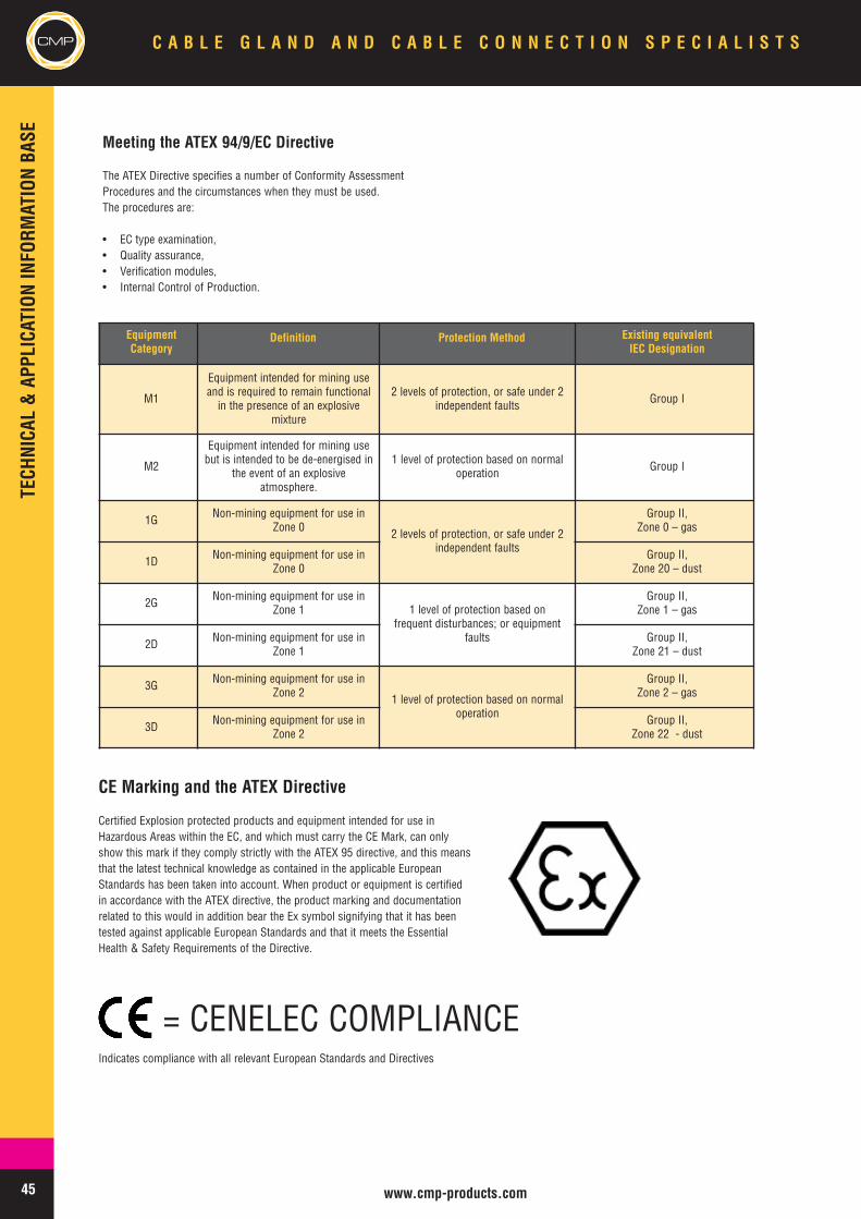
45 www.cmp-products.com
CMP C A B L E G L A N D A N D C A B L E C O N N E C T I O N S P E C I A L I S T S
EquipmentCategory
Definition Protection Method Existing equivalentIEC Designation
M1
Equipment intended for mining useand is required to remain functionalin the presence of an explosive
mixture
2 levels of protection, or safe under 2independent faults Group I
M2
Equipment intended for mining usebut is intended to be de-energised in
the event of an explosiveatmosphere.
1 level of protection based on normaloperation Group I
1G Non-mining equipment for use inZone 0 2 levels of protection, or safe under 2
independent faults
Group II,Zone 0 – gas
1D Non-mining equipment for use inZone 0
Group II,Zone 20 – dust
2G Non-mining equipment for use inZone 1 1 level of protection based on
frequent disturbances; or equipmentfaults
Group II,Zone 1 – gas
2D Non-mining equipment for use inZone 1
Group II,Zone 21 – dust
3G Non-mining equipment for use inZone 2 1 level of protection based on normal
operation
Group II,Zone 2 – gas
3D Non-mining equipment for use inZone 2
Group II,Zone 22 - dust
CE Marking and the ATEX Directive
Certified Explosion protected products and equipment intended for use inHazardous Areas within the EC, and which must carry the CE Mark, can onlyshow this mark if they comply strictly with the ATEX 95 directive, and this meansthat the latest technical knowledge as contained in the applicable EuropeanStandards has been taken into account. When product or equipment is certifiedin accordance with the ATEX directive, the product marking and documentationrelated to this would in addition bear the Ex symbol signifying that it has beentested against applicable European Standards and that it meets the EssentialHealth & Safety Requirements of the Directive.
Indicates compliance with all relevant European Standards and Directives
= CENELEC COMPLIANCE
TECHNICAL&APPLICATIONINFORM
ATIONBASE Meeting the ATEX 94/9/EC Directive
The ATEX Directive specifies a number of Conformity AssessmentProcedures and the circumstances when they must be used.The procedures are:
• EC type examination,• Quality assurance,• Verification modules,• Internal Control of Production.
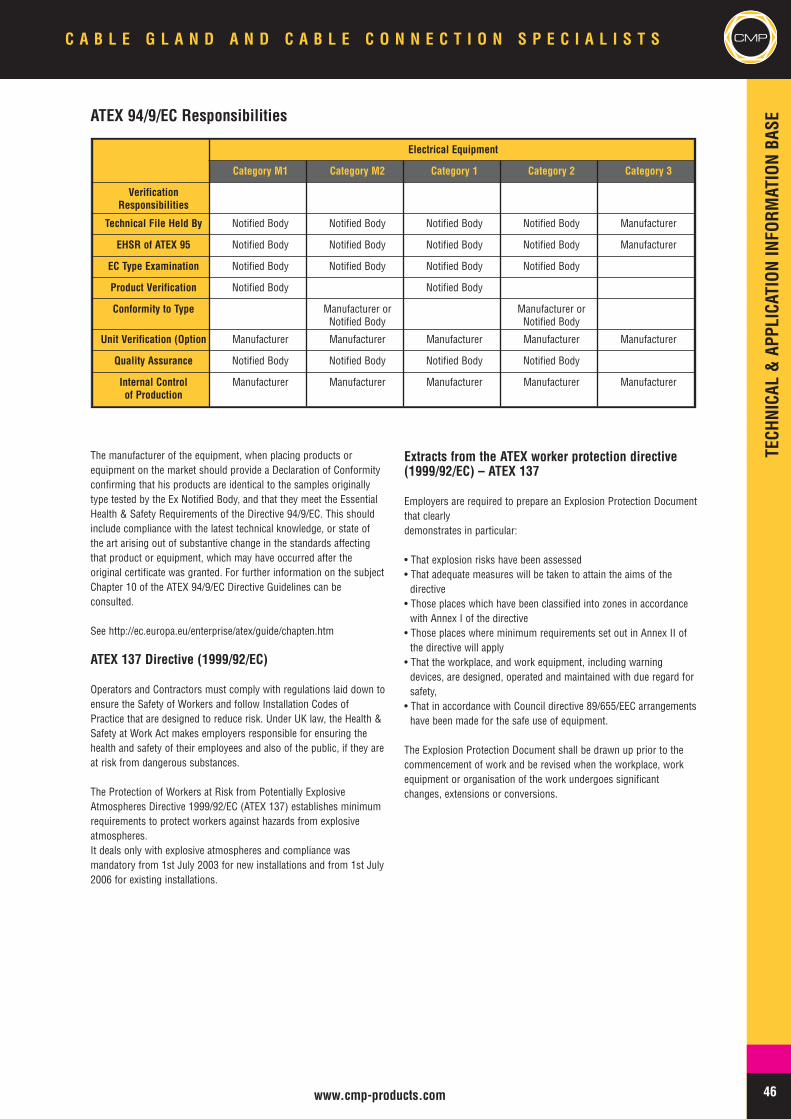
46www.cmp-products.com
CMPC A B L E G L A N D A N D C A B L E C O N N E C T I O N S P E C I A L I S T S
The manufacturer of the equipment, when placing products orequipment on the market should provide a Declaration of Conformityconfirming that his products are identical to the samples originallytype tested by the Ex Notified Body, and that they meet the EssentialHealth & Safety Requirements of the Directive 94/9/EC. This shouldinclude compliance with the latest technical knowledge, or state ofthe art arising out of substantive change in the standards affectingthat product or equipment, which may have occurred after theoriginal certificate was granted. For further information on the subjectChapter 10 of the ATEX 94/9/EC Directive Guidelines can beconsulted.
See http://ec.europa.eu/enterprise/atex/guide/chapten.htm
ATEX 137 Directive (1999/92/EC)
Operators and Contractors must comply with regulations laid down toensure the Safety of Workers and follow Installation Codes ofPractice that are designed to reduce risk. Under UK law, the Health &Safety at Work Act makes employers responsible for ensuring thehealth and safety of their employees and also of the public, if they areat risk from dangerous substances.
The Protection of Workers at Risk from Potentially ExplosiveAtmospheres Directive 1999/92/EC (ATEX 137) establishes minimumrequirements to protect workers against hazards from explosiveatmospheres.It deals only with explosive atmospheres and compliance wasmandatory from 1st July 2003 for new installations and from 1st July2006 for existing installations.
Extracts from the ATEX worker protection directive(1999/92/EC) – ATEX 137
Employers are required to prepare an Explosion Protection Documentthat clearlydemonstrates in particular:
• That explosion risks have been assessed• That adequate measures will be taken to attain the aims of thedirective• Those places which have been classified into zones in accordancewith Annex I of the directive• Those places where minimum requirements set out in Annex II ofthe directive will apply• That the workplace, and work equipment, including warningdevices, are designed, operated and maintained with due regard forsafety,• That in accordance with Council directive 89/655/EEC arrangementshave been made for the safe use of equipment.
The Explosion Protection Document shall be drawn up prior to thecommencement of work and be revised when the workplace, workequipment or organisation of the work undergoes significantchanges, extensions or conversions.
Electrical Equipment
Category M1 Category M2 Category 1 Category 2 Category 3
VerificationResponsibilities
Technical File Held By Notified Body Notified Body Notified Body Notified Body Manufacturer
EHSR of ATEX 95 Notified Body Notified Body Notified Body Notified Body Manufacturer
EC Type Examination Notified Body Notified Body Notified Body Notified Body
Product Verification Notified Body Notified Body
Conformity to Type Manufacturer orNotified Body
Manufacturer orNotified Body
Unit Verification (Option Manufacturer Manufacturer Manufacturer Manufacturer Manufacturer
Quality Assurance Notified Body Notified Body Notified Body Notified Body
Internal Controlof Production
Manufacturer Manufacturer Manufacturer Manufacturer Manufacturer
ATEX 94/9/EC Responsibilities
TECHNICAL&APPLICATIONINFORM
ATIONBASE
47 www.cmp-products.com
CMP C A B L E G L A N D A N D C A B L E C O N N E C T I O N S P E C I A L I S T S
UK DSEAR Regulations 2002 & EC Chemical Agents(C.A.D.)
In the United Kingdom, the Dangerous Substances in ExplosibleAtmospheres Regulations (DSEAR) which came into force onDecember 9th 2002, requires operators, under a Statutory Instrument(S.I. 2002 Number 2776) of the UK government, to make use of theATEX 137 and the EC Chemical Agents (CAD) 98/24/EC directives toensure safety in the work place.
The ultimate object of the legislation is to ensure that as a minimum,the Essential Health and Safety requirements of the new approachdirectives are met.
Further information can be obtained from :-
Safety Policy Directorate of the UK Health & Safety Executive -http://www.hse.gov.uk/spd/The official publication of the European Communities ATEX Directives– found at Europa –http://europa.eu.int/comm/enterprise/atex/guide/index.htmList of European Standardisation Organisations -http://europa.eu.int/comm/enterprise/newapproach/standardization/harmstds/Standards & Technical Regulations Directorate of the UK GovernmentDepartment of Trade & Industry - http://www.dti.gov.uk/strd/atex.htm
NON ELECTRICAL EQUIPMENT
The need for non electrical apparatus to be assessed, tested, rated,labelled and certified for use in potentially explosive atmospheres wasintroduced for the first time as part of the implementation of the
ATEX Directives 94/9/EC & 1999/92/EC. Here is a summary of thestandards that have been established against which the non electricalapparatus should be tested.
EN 13463-1:2001 Non electrical equipment for use in potentially explosive atmospheres – Basic method and requirements
EN 13463-2:2004 Non electrical equipment for use in potentially explosive atmospheres – Protection by flow restricting enclosure(symbol: fr) - The explosive atmosphere is prevented from reaching the ignition source by the tight seals of theenclosure. The seals restrict the breathing of the enclosure as internal air heats and cools through operation of
the equipment.
EN 13463-3:2005 Non electrical equipment for use in potentially explosive atmospheres – Protection by flemeproof enclosure(symbol: d) - An ignition inside the equipment does not propagate the external atmosphere. This type of
protection relies on closely machined joints and a robust enclosure.
prEN 13463-4 Non electrical equipment for use in potentially explosive atmospheres – Protection by inherent safety(symbol: g) - low potential energy
EN 13463-5:2003 Non electrical equipment for use in potentially explosive atmospheres – Protection by by constructional safety(symbol: c) - Ignition hazards are eliminated by the specification of the equipment.
EN 13463-6:2005 Non electrical equipment for use in potentially explosive atmospheres – Protection by control of ignitionsources (symbol: b) - sources of ignition are only present in the event of a malfunction. The equipment is fitted
with control equipment to detect malfunctions and prevent ignition sources arising.
prEN 13463-7 Non electrical equipment for use in potentially explosive atmospheres – Protection by pressurisation (symbol:p) - draft not yet available. In general, the enclosure is purged with a protective gas (air) and pressurised to
ensure that an external atmosphere cannot re-enter the enclosure.
EN 13463-8:2003 Non electrical equipment for use in potentially explosive atmospheres – Protection by liquid immersion(symbol: k) - The enclosure has a suitable liquid to prevent the explosive atmosphere reaching the ignition
source or to cool a hot surface
TECHNICAL&APPLICATIONINFORM
ATIONBASE
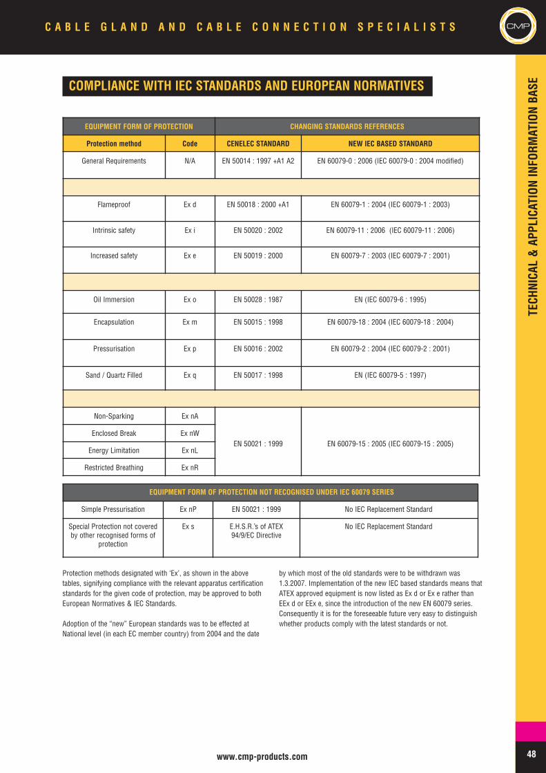
48www.cmp-products.com
CMPC A B L E G L A N D A N D C A B L E C O N N E C T I O N S P E C I A L I S T S
COMPLIANCE WITH IEC STANDARDS AND EUROPEAN NORMATIVES
Protection methods designated with ‘Ex’, as shown in the abovetables, signifying compliance with the relevant apparatus certificationstandards for the given code of protection, may be approved to bothEuropean Normatives & IEC Standards.
Adoption of the “new” European standards was to be effected atNational level (in each EC member country) from 2004 and the date
by which most of the old standards were to be withdrawn was1.3.2007. Implementation of the new IEC based standards means thatATEX approved equipment is now listed as Ex d or Ex e rather thanEEx d or EEx e, since the introduction of the new EN 60079 series.Consequently it is for the foreseeable future very easy to distinguishwhether products comply with the latest standards or not.
EQUIPMENT FORM OF PROTECTION CHANGING STANDARDS REFERENCES
Protection method Code CENELEC STANDARD NEW IEC BASED STANDARD
General Requirements N/A EN 50014 : 1997 +A1 A2 EN 60079-0 : 2006 (IEC 60079-0 : 2004 modified)
Flameproof Ex d EN 50018 : 2000 +A1 EN 60079-1 : 2004 (IEC 60079-1 : 2003)
Intrinsic safety Ex i EN 50020 : 2002 EN 60079-11 : 2006 (IEC 60079-11 : 2006)
Increased safety Ex e EN 50019 : 2000 EN 60079-7 : 2003 (IEC 60079-7 : 2001)
Oil Immersion Ex o EN 50028 : 1987 EN (IEC 60079-6 : 1995)
Encapsulation Ex m EN 50015 : 1998 EN 60079-18 : 2004 (IEC 60079-18 : 2004)
Pressurisation Ex p EN 50016 : 2002 EN 60079-2 : 2004 (IEC 60079-2 : 2001)
Sand / Quartz Filled Ex q EN 50017 : 1998 EN (IEC 60079-5 : 1997)
Non-Sparking Ex nA
EN 50021 : 1999 EN 60079-15 : 2005 (IEC 60079-15 : 2005)Enclosed Break Ex nW
Energy Limitation Ex nL
Restricted Breathing Ex nR
EQUIPMENT FORM OF PROTECTION NOT RECOGNISED UNDER IEC 60079 SERIES
Simple Pressurisation Ex nP EN 50021 : 1999 No IEC Replacement Standard
Special Protection not coveredby other recognised forms of
protection
Ex s E.H.S.R.’s of ATEX94/9/EC Directive
No IEC Replacement StandardTECHNICAL&APPLICATIONINFORM
ATIONBASE
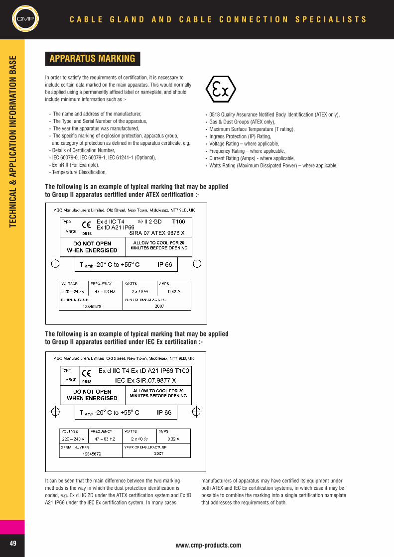
49 www.cmp-products.com
CMP C A B L E G L A N D A N D C A B L E C O N N E C T I O N S P E C I A L I S T S
It can be seen that the main difference between the two markingmethods is the way in which the dust protection identification iscoded, e.g. Ex d IIC 2D under the ATEX certification system and Ex tDA21 IP66 under the IEC Ex certification system. In many cases
manufacturers of apparatus may have certified its equipment underboth ATEX and IEC Ex certification systems, in which case it may bepossible to combine the marking into a single certification nameplatethat addresses the requirements of both.
APPARATUS MARKING
In order to satisfy the requirements of certification, it is necessary toinclude certain data marked on the main apparatus. This would normallybe applied using a permanently affixed label or nameplate, and shouldinclude minimum information such as :-
• The name and address of the manufacturer,• The Type, and Serial Number of the apparatus,• The year the apparatus was manufactured,• The specific marking of explosion protection, apparatus group,and category of protection as defined in the apparatus certificate, e.g.
•Details of Certification Number,• IEC 60079-0, IEC 60079-1, IEC 61241-1 (Optional),•Ex nR II (For Example),•Temperature Classification,
• 0518 Quality Assurance Notified Body Identification (ATEX only),• Gas & Dust Groups (ATEX only),• Maximum Surface Temperature (T rating),• Ingress Protection (IP) Rating,• Voltage Rating – where applicable,• Frequency Rating – where applicable,• Current Rating (Amps) - where applicable,• Watts Rating (Maximum Dissipated Power) – where applicable.
The following is an example of typical marking that may be appliedto Group II apparatus certified under IEC Ex certification :-
The following is an example of typical marking that may be appliedto Group II apparatus certified under ATEX certification :-
TECHNICAL&APPLICATIONINFORM
ATIONBASE
50www.cmp-products.com
CMPC A B L E G L A N D A N D C A B L E C O N N E C T I O N S P E C I A L I S T S
PURPOSE OF CERTIFICATION
Before products, equipment, or protective systems can be selectedfor installation in a hazardous area they should first be certified asbeing suitable for that application. A Certificate of Conformity forequipment intended for use in Explosive Atmospheres is evidencethat the product, equipment or protective system conforms and hasbeen tested to a relevant standard. The Certificate of Conformity willclearly show the standards to which the test were carried out, andwhich edition of the standard was used, and it should also provide aschedule describing the apparatus and any variations ormodifications that have been approved. The Certificate of Conformity
should endorse the type of equipment proposed to be used as beingsafe for its intended use, with any Special Conditions for Safe Use, ifapplicable, clearly spelled out within the document.
It should be noted that the certificate alone does not make aninstallation safe, and there is an obligation on the part of theinstallation contractor and / owner to ensure that the apparatus isinstalled correctly, in a competent manner, and in accordance withthe manufacturers instructions, taking into account any specialconditions for safe use that may exist.
IEC EX CERTIFICATION SCHEME
IEC Ex 02 International Certification SchemeIn addition to the preparation of International Standards, the IECfacilitates the operation of Conformity Assessment Schemes. Onesuch scheme is the IEC Ex 02 Scheme.
The IECEx 02 scheme is a single global certification scheme based onthe International Electrotechnical Commission's internationalstandards.
The IEC Ex Scheme comprises the following two Global CertificationPrograms:1. The IEC Ex Certified Equipment Program2. The IEC Ex Certified Service Facilities Program
This IEC Ex Program is an International Certification Scheme coveringproduct that meets the requirements of International Standardsprepared by TC 31 e.g. IEC 60079 series.
Scheme ObjectiveThe objective of the IEC Ex Scheme is to facilitate international tradein equipment and services for use in explosive atmospheres, whilstmaintaining the required level of safety resulting in:
• Reduced testing and certification costs to manufacturer,• Reduced time to market,• International confidence in the product assessment process,• One international database listing,• Maintaining International Confidence in equipment and services
covered by IEC Ex Certification.
The IEC Ex Certified Equipment Program provides both:
a) A single International Certificate of Conformity that requiresmanufacturers to successfully complete:-• Testing and assessment of samples for compliance with
Standards,• Assessment and auditing of manufacturers premises,• On-going surveillance audits of manufacturers premises.
or
b) A “fast-track” process for countries where regulations still requirethe issuing of national Ex Certificates or approval. This is achieved byway of global acceptance of IEC Ex equipment Assessment and TestReports.Certificates issued by the IEC Ex Certified Equipment Program areissued as “Electronic Certificates” are live on the IEC Ex Website(www.iecex.com). This enables full public access for viewing andprinting.
2. The IEC Ex Certified Service Facilities Program
This IEC Ex Program is an International Certification Scheme thatcovers the assessment and the on-site audit of organizations thatprovide a repair and overhaul service to the Ex industry. Like the IECEx Certified Equipment Program, only “Electronic Certificates” areissued via the “On-Line” system thereby giving industry full access toboth the viewing and printing of certificates.
Under the IEC 60079 series, IEC Ex and ATEX certificates cover theapproval of products and equipment to the same IEC basedstandards, assuming that the products and equipment have beenapproved to the latest standards. In some countries of the world it isconsidered that IEC Ex certification, which complies with the ISO 5system, is a superior form of approval, and that ATEX is not regardedin the same light, as it involves “self certification”. It is true to saythat under the ATEX 94/9/EC Directive it is possible for manufacturersto have Category 3 (Zone 2) apparatus certified when the type testingwas not carried out, and the corresponding test reports were notwritten by an independent third party Ex Notified Body. In such caseshowever, a third party Ex Notified Body is still required to provide theATEX Certificate of Conformity, but the responsibility for the safety of
the product rests entirely with the manufacturer. Many manufacturerschoose to have type tests conducted by the Ex Notified Body, so it isnot possible to generalise and say that all Category 3, Zone 2products certified under the requirements of the ATEX 94/9/Ecdirective are “self certified”. Furthermore, this method of certificationcannot be applied to Category 1 (Zone 0) or Category 2 (Zone 1)apparatus. The method of certification allowed for Zone 2 (Category3) apparatus is not a new idea, this has been the case before theATEX directive became a compulsory force in the EC, but because thepractice was already in existence for quite some time, and withoutany real difficulties being experienced, this was subsequentlyincluded within the parameters of ATEX.
Similarities between IEC Ex & ATEX Approval
TECHNICAL&APPLICATIONINFORM
ATIONBASE
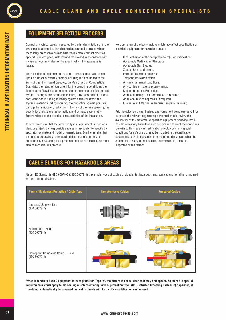
51 www.cmp-products.com
CMP C A B L E G L A N D A N D C A B L E C O N N E C T I O N S P E C I A L I S T S
CABLE GLANDS FOR HAZARDOUS AREAS
Under IEC Standards (IEC 60079-0 & IEC 60079-1) three main types of cable glands exist for hazardous area applications, for either armouredor non armoured cables.
When it comes to Zone 2 equipment form of protection Type ‘n’, the picture is not so clear as it may first appear. As there are specialrequirements which apply to the sealing of cables entering form of protection type ‘nR’ (Restricted Breathing Enclosure) apparatus, itshould not automatically be assumed that cable glands with Ex d or Ex e certification can be used.
Form of Equipment Protection / Cable Type Non-Armoured Cables Armoured Cables
Increased Safety – Ex e(IEC 60079-7)
Flameproof – Ex d(IEC 60079-1)
Flameproof Compound Barrier – Ex d(IEC 60079-1)
EQUIPMENT SELECTION PROCESS
Generally, electrical safety is ensured by the implementation of one oftwo considerations, i.e. that electrical apparatus be located wherereasonably practicable outside hazardous areas, and that electricalapparatus be designed, installed and maintained in accordance withmeasures recommended for the area in which the apparatus islocated.
The selection of equipment for use in hazardous areas will dependupon a number of variable factors including but not limited to theZone of Use, the Hazard Category, the Gas Group or CombustibleDust data, the rating of equipment for the operating conditions, theTemperature Classification requirement of the equipment (determinedby the T Rating of the flammable mixture), any construction materialconsiderations including reliability against chemical attack, theIngress Protection Rating required, the protection against possibledamage from vibration, reduction in the risk of thermite sparking, thepossibility of static charge formation, and perhaps several otherfactors related to the electrical characteristics of the installation.
In order to ensure that the preferred type of equipment is used on aplant or project, the responsible engineers may prefer to specify theapparatus by make and model or generic type. Bearing in mind thatthe most progressive and forward thinking manufacturers arecontinuously developing their products the task of specification mustalso be a continuous process.
Here are a few of the basic factors which may affect specification ofelectrical equipment for hazardous areas :-
• Clear definition of the acceptable form(s) of certification,• Acceptable Certification Standards,• Acceptable Gas Groups,• Zone of Use requirement,• Form of Protection preferred,• Temperature Classification,• Any environmental conditions,• Any particular material requirements,• Minimum Ingress Protection,• Additional Deluge Test Certification, if required,• Additional Marine approvals, if required,• Minimum and Maximum Ambient Temperature rating.
Prior to selection being finalised and equipment being earmarked forpurchase the relevant engineering personnel should review theavailability of the preferred or specified equipment, verifying that ithas the necessary hazardous area certification to meet the conditionsprevailing. This review of certification should cover any specialconditions for safe use that may be included in the certificationdocuments to avoid subsequent non-conformities arising when theequipment is ready to be installed, commissioned, operated,inspected or maintained.
TECHNICAL&APPLICATIONINFORM
ATIONBASE
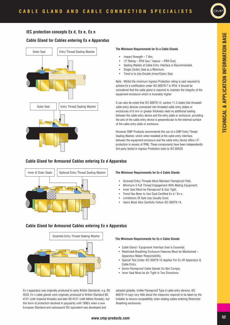
52www.cmp-products.com
CMPC A B L E G L A N D A N D C A B L E C O N N E C T I O N S P E C I A L I S T S
IEC protection concepts Ex d, Ex e, Ex n
Cable Gland for Cables entering Ex e Apparatus
The Minimum Requirements for Ex e Cable Glands
• Impact Strength – 7 Nm,• I.P. Rating – IP54 Gas / Vapour – IP6X Dust,• Sealing Washer at Cable Entry Interface is Recommended,• Single (Outer) Seal as a Minimum,• Trend is to Use Double (Inner/Outer) Seal.
Note : Whilst the minimum Ingress Protection rating is said required toachieve Ex e certification under IEC 60079-7 is IP54, it should beconsidered that the cable gland is required to maintain the integrity of theequipment enclosure which is invariably higher.
It can also be noted that IEC 60079-14, section 11.3 states that threadedcable entry devices connected into threaded cable entry plates orenclosures of 6 mm or greater thickness need no additional sealingbetween the cable entry device and the entry plate or enclosure, providingthe axis of the cable entry device is perpendicular to the external surfaceof the cable entry plate or enclosure.
However CMP Products recommends the use of a CMP Entry ThreadSealing Washer, which when installed at the cable entry interface,between the equipment enclosure and the cable entry device offers I.P.protection in excess of IP66. These components have been independently3rd party tested in Ingress Protection tests to IEC 60529.
Ex n apparatus was originally produced to early British Standards, e.g. BS4533. Ex n cable glands were originally produced to British Standard BS4121 (with Imperial threads) and later BS 6121 (with Metric threads), butthis form of protection declined in popularity until 1990’s when a newEuropean Standard and subsequent IEC equivalent was developed and
adopted globally. Unlike Flameproof Type d cable entry devices, IEC60079-14 says very little about the measures required to be taken by theinstaller to ensure compatibility when sealing cables entering RestrictedBreathing enclosures.
The Minimum Requirements for Ex d Cable Glands
• Screwed Entry Threads Must Maintain Flameproof Path,• Minimum 5 Full Thread Engagement With Mating Equipment,• Inner Seal Must be Flameproof & Gas Tight,• Trend Has Been to Use Dual Certified Ex d / Ex e,• Limitations Of Safe Use Usually Exist,• Users Must Also Carefully Follow IEC 60079-14.
The Minimum Requirements for Ex n Cable Glands
• Cable Gland / Equipment Interface Seal is Essential,• Restricted Breathing Enclosure Features Must be Maintained –Apparatus Maker Responsibility,
• Special Test Under IEC 60079-15 Applies For Ex nR Apparatus &Cable Entry,
• Some Flameproof Cable Glands Do Not Comply,• Inner Seal Must be Air Tight in Two Directions.
Cable Gland for Armoured Cables entering Ex n Apparatus
Cable Gland for Armoured Cables entering Ex d Apparatus
Outer Seal Entry Thread Sealing Washer
Outer Seal Entry Thread Sealing Washer
Essential Entry Thread Sealing Washer
Optional Entry Thread Sealing WasherInner & Outer Seals
TECHNICAL&APPLICATIONINFORM
ATIONBASE
53 www.cmp-products.com
CMP C A B L E G L A N D A N D C A B L E C O N N E C T I O N S P E C I A L I S T S
MARKING OF CABLE GLANDS FOR HAZARDOUS AREAS
Cable Glands are classified as being equipment and would usually bemarked with the same or similar information as would be applicablefor main apparatus. However it should be noted that because of thenature of and relatively small size of the product certain exceptionsexist. For example as cable glands are passive in respect of theoperation of the electrical system they are not given a SurfaceTemperature rating (T Rating) during the certification process. Inaddition because of the amount of marking required and the size
limitations of the letters used in applying the marking it is permittedto display information such as the CE mark and year of manufactureon the packaging instead of on the product itself. CMP Cable Glandswould typically be marked in the following manner to demonstratecompliance with the EU ATEX Directive 94/9/EC, and IEC Ex 02Certification Scheme, which embraces both CENELEC and IECstandards EN 60079 & IEC 60079 :-
Example A : CMP E1FW Cable Gland
Line 1
CMP UK (20) E1FW (M20) -60oC to +130oC 0518
Manufacturer’sName orTrademark
Gland SizeManufacturer’sProduct TypeIdentification
CommunityMark
QA NotifiedBody Number
ThreadSize
Please note that values shown in brackets above are variables that would change according to cable gland or thread size
Line 2
SIRA 06 ATEX1097X
Year ofCertification
Apparatus Group‘X’ for Special ConditionsFor Safe Use
IEC Ex CertificateNumber
II 2/3GD IEC Ex SIR.06.0043X
Testing StationIdentification
ATEX CertificateNumber
Symbol Signifies FullCompliance with
European Standards
ATEX Category /Gas or Dust Groups
Line 3
Ex d I / Ex e I / Ex d IIC / Ex e II / Ex nR II / Ex tD A21 IP66
Group IForms of Protection
Group IIForms of Protection
IEC Ex Dust Protection
Some products in the CMP cable gland range may be required to include additional marking for example that requiredunder UL or CSA certification, as shown opposite.
TECHNICAL&APPLICATIONINFORM
ATIONBASE
OperatingTemperature Range
54www.cmp-products.com
CMPC A B L E G L A N D A N D C A B L E C O N N E C T I O N S P E C I A L I S T S
IEC Ex CertificateNumber
Group IIForms of Protection
IEC Ex Dust Protection
CL I DIV 2 ABCD, CL II DIV 2 EFG, CL III Ex d IIC / Ex e, 4X
CSA Logo CanadianForms of Protection
UL Logo
Year ofCertification
ApparatusGroup
‘X’ for Special ConditionsFor Safe Use
Testing StationIdentification
ATEX CertificateNumber
Symbol Signifies FullCompliance with
European Standards
ATEX Category /Gas or DustGroups
CommunityMark
TECHNICAL&APPLICATIONINFORM
ATIONBASE
Example B : CMP T3CDS Cable Gland
Line 1
CMP UK (20) T3CDS (M20) SIRA 06 ATEX1283X II 2/3GD 0518
Manufacturer’sName orTrademark
Gland SizeManufacturer’sProduct TypeIdentification
QA NotifiedBody Number
ThreadSize
Please note that values shown in brackets above are variables that would change according to cable gland or thread size.
Line 2
IECEx SIR.07.0005X Ex d IIC / Ex e II / Ex nR II / Ex tD A21 IP66
Line 3
Line 4
-60ºC to +130ºC CL I Zone 1,2, AEx e II, TYPE 4X OIL RES II
Operating TemperatureRange
North AmericanForms of Protection
Ingress Protection
Ingress Protection
55 www.cmp-products.com
CMP C A B L E G L A N D A N D C A B L E C O N N E C T I O N S P E C I A L I S T S
SELECTION OF CABLES INTENDED FOR USE IN HAZARDOUS AREAS
Cables come in a wide variety of shapes and sizes and new designs,e.g. those with optical fibres, are regularly being introduced.
The issue of correctly sealing these cables as they enter hazardousarea electrical equipment is a worldwide problem, and not confinedpurely to local conditions in any one particular place.
Although there are no IEC construction standards for the cablesintended for use in flammable atmospheres, according to IEC 60079-14:2002, 10.4.2(b), if a cable gland with an elastomeric flameproofsealing ring is to be used, when connecting cables to Ex d equipmentenclosures, the cable should be :-
i. Substantially compact and circular (i.e. especially the part of thecable entering the enclosure),
ii. Have an extruded bedding (without any gaps),iii. Have fillers, if any are used, which are Non-Hygroscopic ?.
Effectively, the cable should be physically assessed, taking intoaccount the protection method and configuration of the equipment, toverify its suitability, before any cable gland with an elastomeric sealingring can be selected.
Typical IEC Cable Types
Until such times when an IEC standard for cables for use in HazardousAreas has been developed and implemented, this applies to all typesof cables used in flammable atmospheres, including :-
Unarmoured
Armoured
TECHNICAL&APPLICATIONINFORM
ATIONBASE
Wire BraidArmour
Single WireArmour (SWA)
Steel TapeArmour (STA)
NormalUnarmoured
56www.cmp-products.com
CMPC A B L E G L A N D A N D C A B L E C O N N E C T I O N S P E C I A L I S T S
COMPATIBILITY OF EQUIPMENT, CABLE AND CABLE GLAND
Equipment & Cable Gland Compatibility
It is important to ensure that the Cable Gland is capable ofmaintaining the integrity of the equipment that it is engaged with.
According to IEC 60079-14:2002, 14.3.2 (under “Additionalrequirements for apparatus suitable only for use in Zone 2”) it statesthat :-
“The connection of cables shall be carried out by means of cable entrydevices appropriate to the type of cable used.”
“To meet the degree of protection requirement of the terminalenclosure, it may be necessary to use cable entry devicesincorporating sealing components to seal between the cable entrydevice and the cable. Sealing may be similarly required between thecable entry device and the enclosure. (for example by means of asealing washer or thread sealant).”
“The sealing of restricted-breathing enclosures shall be such as tomaintain the restricted-breathing properties of the enclosure.”
Interestingly some Ex d cable glands have a problem in maintainingthe restricted-breathing characteristics under the prevailing testconditions.
Restricted Breathing Ex nR Equipment
Protection Method Type nR (Restricted Breathing Enclosure, from theEx ‘n’ Family).
Usually Ex n Equipment contains components that are non – sparking.Restricted Breathing Enclosures Type nR ensure that the flammablegas is kept away from any hot surfaces and ignition capablecomponents (i.e. arcing / sparking)
1. Light weight enclosure of metallic or non metallic construction.2. High Ingress Protection levels must be maintained.3. Not designed to withstand explosion.4. Enclosure must be tightly sealed and gasketed and not allowed tobreathe freely.
5. Amount of gas allowed to penetrate the enclosure is insufficient toreach the LEL, otherwise explosion could occur (see 3).
Large volumes of gas should not exist within the enclosure, & theprotection method requires the gas to kept away from the source ofignition, so as to avoid explosion & external transmission.
Extract from IEC 60079-15:2005 (3rd Edition)
Electrical Apparatus for Potentially Explosive Atmospheres – TypeProtection ‘n’
Section 22 Restricted Breathing Enclosures (Page 34) - Sub-Section 22.6
Restricted Breathing enclosures without the provision for carrying outchecks after installation or maintenance shall be type tested including thecable entry device. Note : The installation instructions provided with theapparatus should contain information on the selection of entry devicesand cables.
Section 26 – Type Tests - Sub-Section 26.826.8.2 – Apparatus without provision for routine checking of restrictedbreathing properties.
Under constant temperature conditions, the time interval required for aninternal pressure of 3 kPa (300mm Water Gauge) below atmospheric tochange to 1.5 kPa (150mm Water Gauge) below atmospheric shall notbe less than 3 minutes.
As the principal of Ex nR protection is required to keep sufficient quantityof the flammable mixture away from any internal ignition capableequipment and hot surfaces, this involves the use of a two way air tightand gas tight seal around the cable, and this is not possible with some(Ex d) cable gland types that include diaphragm type seals.
The important thing to remember is that not all Ex d, or Ex e, or DualCertified (Ex d & Ex e) cable glands are able to meet the compatibilityrequirements for all protection forms in Zone 1 and Zone 2 hazardousareas, with particular emphasis on the Restricted Breathing enclosureconcept.
CMP Products has gone to the extent of obtaining Ex nR certificationfor its range of double seal cable glands to EN 60079-15 / IEC 60079-15.
TECHNICAL&APPLICATIONINFORM
ATIONBASE
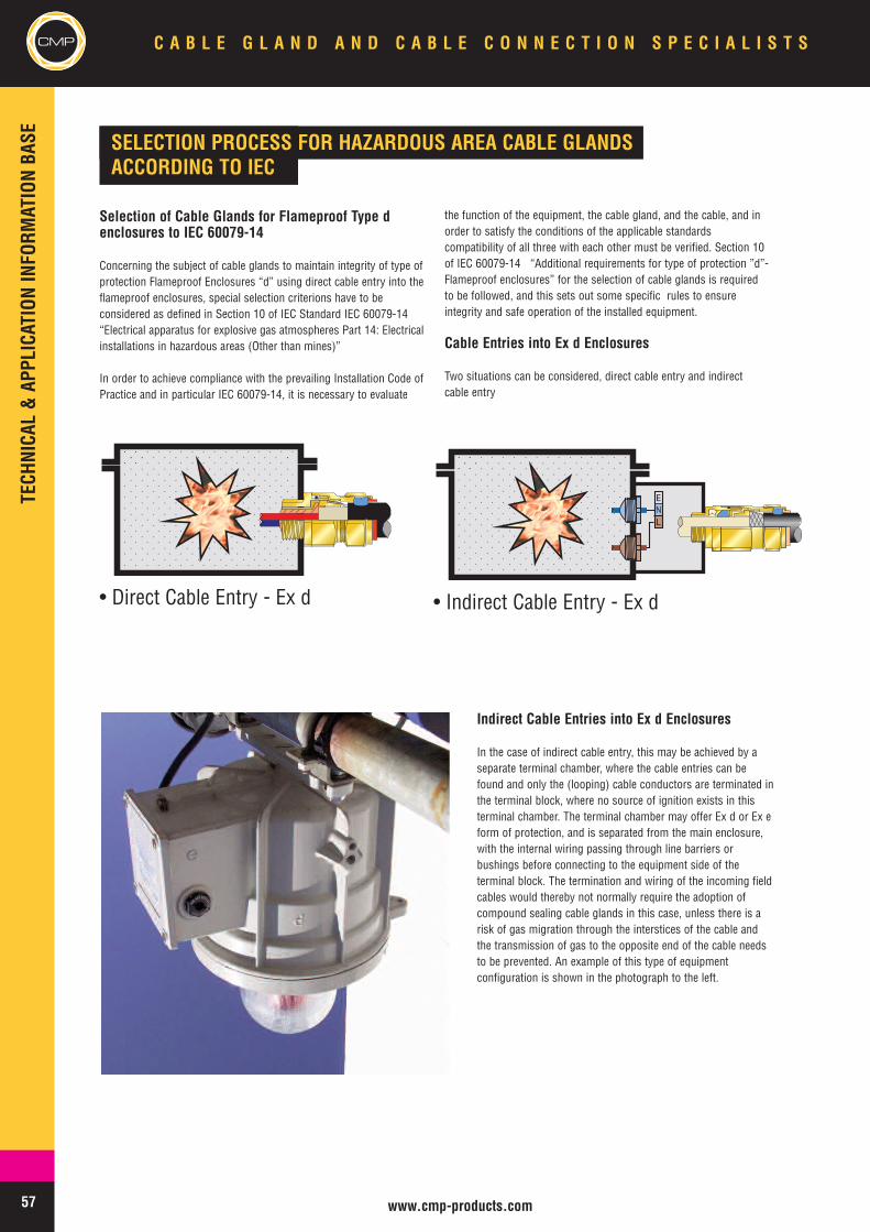
57 www.cmp-products.com
CMP C A B L E G L A N D A N D C A B L E C O N N E C T I O N S P E C I A L I S T S
Indirect Cable Entries into Ex d Enclosures
In the case of indirect cable entry, this may be achieved by aseparate terminal chamber, where the cable entries can befound and only the (looping) cable conductors are terminated inthe terminal block, where no source of ignition exists in thisterminal chamber. The terminal chamber may offer Ex d or Ex eform of protection, and is separated from the main enclosure,with the internal wiring passing through line barriers orbushings before connecting to the equipment side of theterminal block. The termination and wiring of the incoming fieldcables would thereby not normally require the adoption ofcompound sealing cable glands in this case, unless there is arisk of gas migration through the interstices of the cable andthe transmission of gas to the opposite end of the cable needsto be prevented. An example of this type of equipmentconfiguration is shown in the photograph to the left.
SELECTION PROCESS FOR HAZARDOUS AREA CABLE GLANDSACCORDING TO IEC
Selection of Cable Glands for Flameproof Type denclosures to IEC 60079-14
Concerning the subject of cable glands to maintain integrity of type ofprotection Flameproof Enclosures “d” using direct cable entry into theflameproof enclosures, special selection criterions have to beconsidered as defined in Section 10 of IEC Standard IEC 60079-14“Electrical apparatus for explosive gas atmospheres Part 14: Electricalinstallations in hazardous areas (Other than mines)”
In order to achieve compliance with the prevailing Installation Code ofPractice and in particular IEC 60079-14, it is necessary to evaluate
the function of the equipment, the cable gland, and the cable, and inorder to satisfy the conditions of the applicable standardscompatibility of all three with each other must be verified. Section 10of IEC 60079-14 “Additional requirements for type of protection ”d”-Flameproof enclosures” for the selection of cable glands is requiredto be followed, and this sets out some specific rules to ensureintegrity and safe operation of the installed equipment.
Cable Entries into Ex d Enclosures
Two situations can be considered, direct cable entry and indirectcable entry
• Direct Cable Entry - Ex d • Indirect Cable Entry - Ex d
TECHNICAL&APPLICATIONINFORM
ATIONBASE
LNE
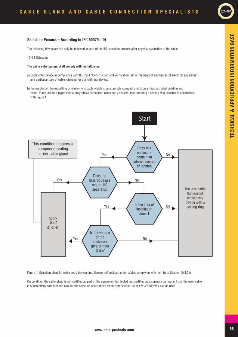
Start
Apply10.4.2d) or e)
Is the volumeof the
enclosuregreater than
2 dm
Is the area ofinstallation
Zone 1
Does the hazardous gas
require IIC apparatus
Does this enclosure contain an
internal source of ignition
Use a suitableflameproof cable entry
device with asealing ring
3
Yes No
No
No
No
Yes
Yes
Yes
This condition requires acompound sealingbarrier cable gland
58www.cmp-products.com
CMPC A B L E G L A N D A N D C A B L E C O N N E C T I O N S P E C I A L I S T S
Selection Process – According to IEC 60079 : 14
The following flow chart can only be followed as part of the IEC selection process after physical evaluation of the cable
10.4.2 Selection
The cable entry system shall comply with the following:
a) Cable entry device in compliance with IEC 79-1 “Construction and verification test of flameproof enclosures of electrical apparatus”and particular type of cable intended for use with that device,
b) thermoplastic, thermosetting or elastomeric cable which is substantially compact and circular, has extruded bedding andfillers, if any, are non-hygroscopic, may utilize flameproof cable entry devices, incorporating a sealing ring selected in accordancewith figure 1,
Figure 1: Selection chart for cable entry devices into flameproof enclosures for cables complying with item b) of Section 10.4.2.b.
On condition the cable gland is not certified as part of the equipment but tested and certified as a separate component and the used cableis substantially compact and circular the selection chart above taken from section 10 of EN/ IEC60079-1 can be used .
TECHNICAL&APPLICATIONINFORM
ATIONBASE
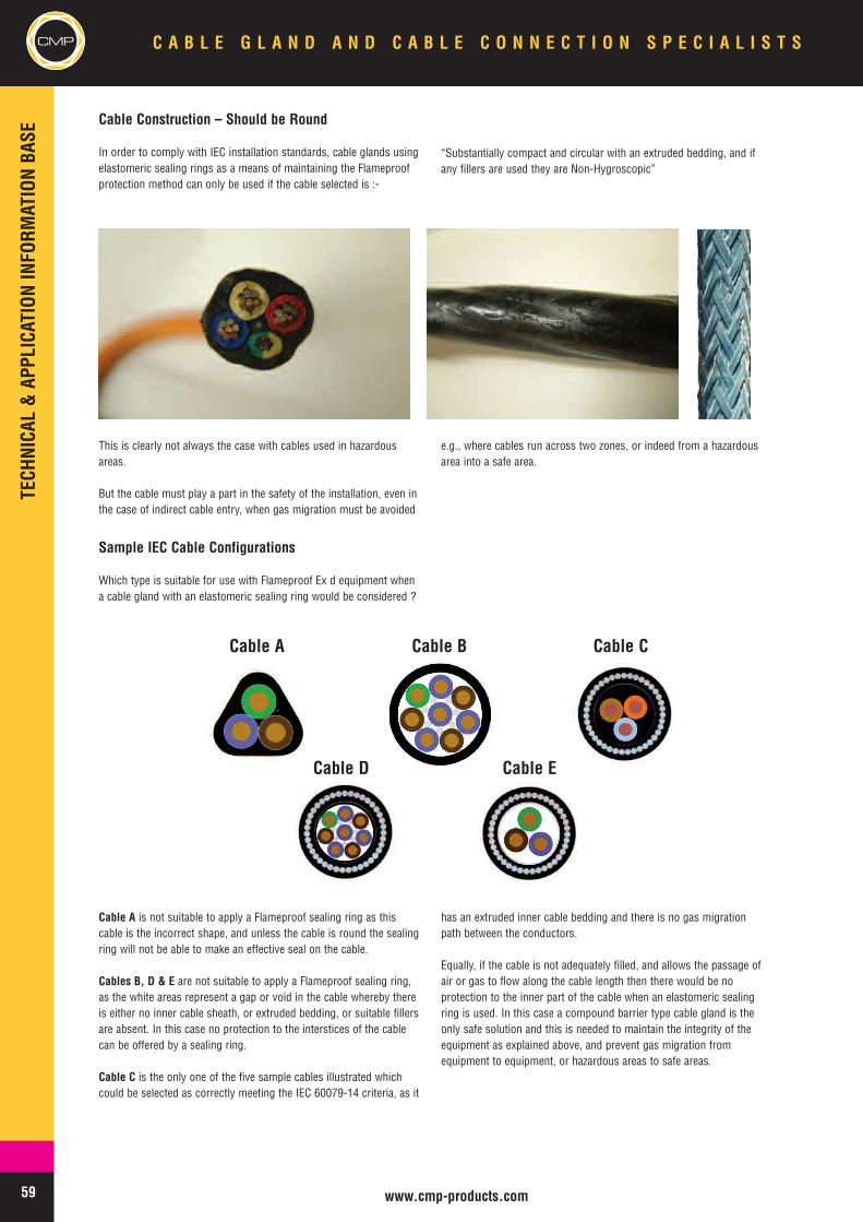
59 www.cmp-products.com
CMP C A B L E G L A N D A N D C A B L E C O N N E C T I O N S P E C I A L I S T S
Cable Construction – Should be Round
In order to comply with IEC installation standards, cable glands usingelastomeric sealing rings as a means of maintaining the Flameproofprotection method can only be used if the cable selected is :-
“Substantially compact and circular with an extruded bedding, and ifany fillers are used they are Non-Hygroscopic”
Sample IEC Cable Configurations
Which type is suitable for use with Flameproof Ex d equipment whena cable gland with an elastomeric sealing ring would be considered ?
This is clearly not always the case with cables used in hazardousareas.
But the cable must play a part in the safety of the installation, even inthe case of indirect cable entry, when gas migration must be avoided
e.g., where cables run across two zones, or indeed from a hazardousarea into a safe area.
Cable A is not suitable to apply a Flameproof sealing ring as thiscable is the incorrect shape, and unless the cable is round the sealingring will not be able to make an effective seal on the cable.
Cables B, D & E are not suitable to apply a Flameproof sealing ring,as the white areas represent a gap or void in the cable whereby thereis either no inner cable sheath, or extruded bedding, or suitable fillersare absent. In this case no protection to the interstices of the cablecan be offered by a sealing ring.
Cable C is the only one of the five sample cables illustrated whichcould be selected as correctly meeting the IEC 60079-14 criteria, as it
has an extruded inner cable bedding and there is no gas migrationpath between the conductors.
Equally, if the cable is not adequately filled, and allows the passage ofair or gas to flow along the cable length then there would be noprotection to the inner part of the cable when an elastomeric sealingring is used. In this case a compound barrier type cable gland is theonly safe solution and this is needed to maintain the integrity of theequipment as explained above, and prevent gas migration fromequipment to equipment, or hazardous areas to safe areas.
Cable A Cable B Cable C
Cable D Cable E
TECHNICAL&APPLICATIONINFORM
ATIONBASE
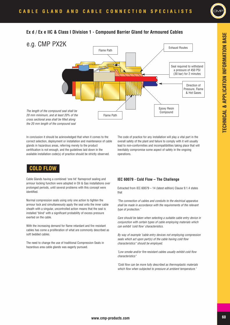
60www.cmp-products.com
CMPC A B L E G L A N D A N D C A B L E C O N N E C T I O N S P E C I A L I S T S
Ex d / Ex e IIC & Class I Division 1 - Compound Barrier Gland for Armoured Cables
In conclusion it should be acknowledged that when it comes to thecorrect selection, deployment or installation and maintenance of cableglands in hazardous areas, referring merely to the productcertification is not enough, and the guidelines laid down in theavailable installation code(s) of practice should be strictly observed.
The code of practice for any installation will play a vital part in theoverall safety of the plant and failure to comply with it will usuallylead to non-conformities and incompatibilities taking place that willinevitably compromise some aspect of safety in the ongoingoperations.
COLD FLOW
Cable Glands having a combined ‘one hit’ flameproof sealing andarmour locking function were adopted in Oil & Gas installations overprolonged periods, until several problems with this concept wereidentified.
Normal compression seals using only one action to tighten thearmour lock and simultaneously apply the seal onto the inner cablesheath with a singular, uncontrolled action means that the seal isinstalled "blind" with a significant probability of excess pressureexerted on the cable.
With the increasing demand for flame retardant and fire resistantcables has come a proliferation of what are commonly described assoft bedded cables.
The need to change the use of traditional Compression Seals inhazardous area cable glands was eagerly pursued.
IEC 60079 - Cold Flow – The Challenge
Extracted from IEC 60079 – 14 (latest edition) Clause 9.1.4 statesthat
"The connection of cables and conduits to the electrical apparatusshall be made in accordance with the requirements of the relevanttype of protection."
Care should be taken when selecting a suitable cable entry device inconjunction with certain types of cable employing materials whichcan exhibit ‘cold flow’ characteristics.
By way of example "cable entry devices not employing compressionseals which act upon part(s) of the cable having cold flowcharacteristics“ should be employed.
"Low smoke and/or fire-resistant cables usually exhibit cold flowcharacteristics“
"Cold flow can be more fully described as thermoplastic materialswhich flow when subjected to pressure at ambient temperature."
Flame Path
Flame Path
Epoxy ResinCompound
Seal required to withstanda pressure of 450 PSI(30 bar) for 2 minutes
Direction ofPressure, Flame& Hot Gases
The length of the compound seal shall be20 mm minimum, and at least 20% of thecross sectional area shall be filled alongthe 20 mm length of the compound seal
e.g. CMP PX2KExhaust Routes
TECHNICAL&APPLICATIONINFORM
ATIONBASE
61 www.cmp-products.com
CMP C A B L E G L A N D A N D C A B L E C O N N E C T I O N S P E C I A L I S T S
Cable Construction – The Factors
Cables installed in practice are unlike anything experienced under testconditions when mandrels are used.
With Low Smoke & Fume Cables, the cable manufacturer’scompound mix, manufacturing and curing process impact on the finalshore hardness of the cable inner bedding, but these are not alone indamage from compression seals. (WRAPPING ONLY)
The impact of compression seals on the cable inner bedding can beseen even on cables without soft inner bedding, and this should beavoided at all times.
Control over the tightening of the inner seal is important, and CMPProducts firmly believes that it has the answer.
Cable Construction – The Factors
1. There are no standards for cable suitability for hazardous areas.2. Cable glands, when tested for hazardous area compliance, are
subjected to hydrostatic pressure tests to prove the effect of theflameproof seal during explosion conditions, and these tests aredone on polished smooth tubular steel mandrels.
3. There are no standards for the definition of soft bedded cables interms of material composition or construction.
4. Subsequently one cable compared with another made to the“same standards” may be different in the extreme.
5. Cables installed in practice are unlike anything experienced undertest conditions when considering 2. above.
RISK ASSESSMENT FACTORS AFFECTING CABLE GLAND SELECTION
In the event that a new high profile “Greenfield” project was to be developed, a major operating company may wish to go to extreme lengths inevaluating vendor prior to confirming contract award. This may incorporate a complete and comprehensive risk assessment process. Thereasons for the implementation of such a demanding examination of risk can be explained by the factors detailed below :-
• Environmentally sensitive project• Major Capital Investment• First time operation or new Joint Venture• Changes in technological know how• Increase in the extremes of operating conditions.• New Project - First Venture in New Territory• New Challenge – everything re-evaluated• Success of the venture under close scrutiny
The scope of the Risk Assessment Process may take into account the following :-
Commercial Evaluation
Availability AnalysisReliability AnalysisSupply Chain ManagementAbility to manageReputationProject Quality ProcessProject management of Change ProcessCommercial assurance / warrantyParent Company Guarantee
Technical Evaluation
Compliance with latest standardsSpecification, functionality, & reliability.Compatibility & integrity of certificationCompatibility with specified cable type.Cable & gland management process.Package & site installation management.Reliability & MaintainabilityPrevious track record.Long term performanceProject Risk Management
Cable & Gland ManagementClose co-operation between project engineers, cable, and cable gland vendors
Installation Technique & TrainingEliminate the possibility of incorrect assembly in the cable gland designAdopt a simple and less scientific approach for Installation PersonnelProject personnel to be properly trained & certificated, fully documenting thisTraining to be given to package vendors, & sub-vendors as well as main fabricatorsFollow up Inspection / Verification exercise to be implemented in conjunction with vendor.Vendor to act on behalf of client whilst carrying out its duties, during this process
TECHNICAL&APPLICATIONINFORM
ATIONBASE
62www.cmp-products.com
CMPC A B L E G L A N D A N D C A B L E C O N N E C T I O N S P E C I A L I S T S
INSTALLATION
The installation of equipment that is intended for use in explosiveatmospheres should be carried out by competent personnel in linewith good engineering practice. Codes of Practice, Regulations, orStandards may exist which lay down the requirements for ensuringthat health and safety requirements are met by such installations.The main IEC Installation standards that are in use today for gas /vapour hazards and dust hazards are detailed below.
IEC 60079-14 : Electrical apparatus for explosive gas atmospheres –Part 14: Electrical installations in hazardous areas (other than mines)
IEC 61892-7 : Mobile and fixed offshore units - Electrical installations- Part 7: Hazardous areas
IEC 61241-14 : Electrical apparatus for use in the presence ofcombustible dust - Part 14: Selection and installation
Cable Gland Installation GuidelinesInstallation should only be carried out by a competent person, skilledin the installation of cable glands. Care should be taken to avoiddamage to entry threads when handling and installing cable glands
Cable Glands should not be installed whilst circuits are live. Similarly,following energising of the electrical circuits, cable glands should notbe dismantled or opened until the circuit has been safely de-energised.
Cable Gland components are not interchangeable with those of anyother cable gland manufacturer. It is important to note thatcomponents from one manufacturer's product cannot be used in thatof another, and that modification of a cable gland product willinvalidate the hazardous area certification.
The cable gland is not a user serviceable product and spare parts arenot permitted to be supplied under the certification.
Cable Gland seals are included within the cable gland whendespatched from the factory. There should be no circumstances whereseals need to be removed from the cable gland. Care should be takento avoid exposure of cable gland seals to dirt, hostile substances, e.g.solvents, and other foreign bodies.
Installation AccessoriesDepending upon the specific form of protection of the main equipmentit may be necessary to fit a sealing washer at the cable entry interfaceto maintain the appropriate Ingress Protection level of the enclosure.For Increased Safety (Ex e) equipment, or Increased Safety terminalchambers found on Ex de equipment, a sealing washer isrecommended to maintain the minimum Ingress Protection rating, andshould always be fitted. For other forms of protection, e.g. FlameproofEx d apparatus, the inclusion of a sealing washer is optional.
It can be noted that IEC 60079-14, section 10.4.1 states thatFlameproof (Ex d) cable entry devices may be fitted with a sealingwasher between the entry device and flameproof enclosure providingthat after the washer has been fitted, the applicable threadengagement is still achieved. For parallel threads, the threadengagement is normally five full threads or 8mm, whichever is thegreater.
It can also be noted that IEC 60079-14, section 11.3 states that forIncreased Safety Ex e enclosures, threaded cable entry devices
connected into threaded cable entry plates or enclosures of 6 mm orgreater thickness need no additional sealing between the cable entrydevice and the entry plate or enclosure, providing the axis of the cableentry device is perpendicular to the external surface of the cable entryplate or enclosure.
CMP Sealing Washers, which are installed at the cable entry interface,between the equipment enclosure and the cable entry device (cablegland) have been 3rd party tested in Ingress Protection tests to IEC60529. CMP Products would recommend their use in most typicaloutdoor situations.
Always ensure that the correct fixing accessories provided by CMPProducts are used, as appropriate to secure the cable glands into themating equipment.
In addition to Sealing Washers, CMP Products are also able to provideLocknuts, Earth Tags, and Serrated Washers which should be used asappropriate to the equipment configuration. Usually for any equipmentother than Ex d apparatus, it will be necessary to use as a minimum aLocknut, and also a Serrated Washer if the enclosure of the equipmentor application requires it. The addition of an Earth Tag will dependupon the earth continuity provision of the enclosures installed.
Further information on cable gland accessories can be found on pages173 to 175 of this catalogue.
Installation ToolsAlways use the correct tools, as incorrect tools will inevitably lead tomistakes, potential damage and/or personal injury. Gloves arerecommended when handling and terminating cables and cableglands. Safety and personal protection should be given priority over allother considerations.
Dedicated Cable Gland spanners for each cable gland size are availablefrom CMP Products, and these are recommended for correctlyinstalling the product.
Adjustable spanners and wrenches are not recommended as there is apossibility of slippage that can lead to accidental injury or damage tosurface finish.
Any sharp tools, instruments or knives used to cut or strip the cablesheath should be equipped with a safety blade or other safety featureconsistent with the tool design and intended use.
Braid snips should be used to remove unwanted or excess cable braid.Ensure that braid snips are in good condition and effectively sharpenough to enable a first time clean cut of the cable braid withoutsnagging.
A hacksaw, or other similar tool, should be used to cut armour wires.Hacksaw blades should be checked regularly and replaced when worn,or whenever evidence that a consistent first time clean cut is no longerpossible. Note, when cutting armour wires, care should be taken toavoid cutting into the inner cable bedding or insulation beneath thearmour wires.
Please refer to CMP Products in sourcing tools if required, who wouldbe happy to assist.
TECHNICAL&APPLICATIONINFORM
ATIONBASE
63 www.cmp-products.com
CMP C A B L E G L A N D A N D C A B L E C O N N E C T I O N S P E C I A L I S T S
HAZARDOUS LOCATIONS ACCORDING TO THE NATIONAL ELECTRIC CODE
In North America the standard reference documents for electricalinstallations are the National Electric Code (NEC) for the USA and theCanadian Electrical Code (CEC) for Canada. Electrical Equipment usedin Ordinary, Wet and Hazardous (or Classified) Locations must be‘listed’ by an accredited approval agency for use in the intendedlocation. The hazardous locations include areas in which flammable,combustible or ignitable substances may occur in hazardousamounts. The NEC and CEC codes allow two methods of categorisingHazardous Locations, which are Class and Division, and Class andZone. Electrical Apparatus approved for use in Hazardous Locationsmust be categorised with an Equipment Class and suitable for aspecified Division and Gas Group. Their classification is made in linewith the amount of combustible materials as :-
Class I - Flammable gases, vapours or mistsClass II - Combustible DustsClass III - Ignitable Fibres and Flyings
A similar arrangement of categorising Gas Groups is used in theNorth American / Canadian standards as in IEC standards althoughthe identification of Gas Groups is different. eg. :-
Division Definitions : Division 1 or Division 2Equipment Classified : Class I, Division 1, A B C D
SURFACE TEMPERATURE CLASSIFICATION
UL844 MAXIMUM TEMPERATURE (ºC) IEC 60079
T1 450 T1
T2 300 T2
T2A 280 T2
T2B 260 T2
T2C 230 T2
T2D 215 T2
T3 200 T3
T3A 180 T3
T3B 165 T3
T3C 160 T3
T4 135 T4
T4A 120 T4
T5 100 T5
T6 85 T6
INSPECTION & MAINTENANCE
The subject of Inspection and maintenance is a very important one,as in common with any non-hazardous area installations, thepresence of an inspection and maintenance regime will always beeffective by way of a preventative measure against the risk ofincidents or accidents from arising that may otherwise go unnoticed.
The two main IEC Inspection & Maintenance standards that are in usetoday for gas / vapour hazards and dust hazards are detailed below.
IEC 60079 -17 : Electrical apparatus for explosive gas atmospheres -Part 17: Inspection and maintenance of electrical installations inhazardous areas (other than mines)
IEC 61241 -17 : Electrical apparatus for use in the presence ofcombustible dust - Part 17: Inspection and maintenance of electricalinstallations in hazardous areas (other than mines)
CABLE GLANDS FOR MINING APPLICATION
CMP Products has for many years designed, manufactured andsupplied cable gland products for Group I mining applications, orareas including underground mines where potentially explosiveatmospheres may arise. These are frequently used surface miningand quarrying applications, as well as in deep underground mines,due to the need to utilise robust solutions and for greater ease of use.In some instances the cable gland products are similar to theequivalent Group II certified versions, but they may be required toterminate special mining cables, e.g. Type 63 / Type 64 PWA cablesnot normally associated with other surface industries.
Flameproof cable glands with normal screwed thread connections arestandard, and alternatives with integral spigot mounting flanges arealso available equipped with a two bolt fixing to allow faster connectand disconnect in order to minimise machine down time.
These products are available with both ATEX and IEC Ex certificationto the latest IEC 60079 series standards, and full specification andadditional technical information can be found in the mining section ofthis catalogue.TE
CHNICAL&APPLICATIONINFORM
ATIONBASE
64www.cmp-products.com
CMPC A B L E G L A N D A N D C A B L E C O N N E C T I O N S P E C I A L I S T S
GAS GROUPS
GAS/COMPOUND NATIONAL ELECTRIC CODE ATMOSPHERE IEC 60079 GAS GROUP
ACETYLENE A IIC
CARBON DISULPHIDE B IIC
HYDROGEN B IIC
ETHYLENE OXIDE B IIB
HYDROGEN SULPHIDE C IIB
ETHYLENE C IIB
ACRYLONITRILE D IIA
INDUSTRIAL METHANE D IIA
PROPANE D IIA
ETHYL ACETATE D IIA
The major Approvals bodies authorised for investigation orassessment of electrical equipment include Underwriters Laboratory(UL), Factory Mutual Inc (FM) & Canadian Standards Association(CSA). In some cases, Electrical equipment may also need to meetcertain Marine Standards and comply with the requirements of theUS Coast Guard 14 CFR. It should be noted that the information
provided here reflects the current position but since the NEC and CECcodes are being continuously reviewed and developed, there may beother changes in process which will affect some of the rules andregulations referenced herein which are understood to be correct atthe time of going to print.
CLASSIFICATION OF HAZARDOUS LOCATIONS, CLASS & DIVISION,CLASS & ZONES
NEC & CEC Hazardous Location Class & DivisionDefinitions
Class I Locations are those in which flammable gases or vapors are,or may be, present in the air in quantities sufficient to produceexplosive or ignitable mixtures.
Class I, Division 1 Location1. Where hazardous concentrations of flammable gases or vapors
exist continuously, intermittently, or periodically under normalconditions,
2. Where hazardous concentrations of such gases or vapors mayexist frequently because of repair or maintenance operations orbecause of leakage, or
3. Where breakdown or faulty operation of equipment or processeswhich might release hazardous concentrations of flammable gasesor vapors, might also cause Simultaneous failure of electricalequipment.
Class I, Division 2 Location1. Where flammable volatile liquids or flammable gases are handled,
processed or used, but in which the hazardous liquids, vapors, orgases will normally be confined within closed containers or closedsystems from which they can escape only in case of accidentalrupture or breakdown of such containers or systems, or in case ofabnormal operation of equipment,
2. Where hazardous concentrations of gases or vapors are normallyprevented by Positive mechanical ventilation, but which mightbecome hazardous through failure or abnormal operation of theventilating equipment, or
3. Which are adjacent to Class I, Division 1 locations, and to whichhazardous concentrations of gases or vapors might occasionallybe communicated unless such communication is prevented byadequate positive pressure ventilation from a source of clean air,and effective safeguards against ventilation failure are provided.
Class II Locations are those which are hazardous due to thepresence of Combustible dust.
Class III Locations are those which are hazardous due to thepresence of easily ignitable fibers or flyings, but in which such fibersor flyings are not likely to be in suspension in air in quantitiessufficient to produce ignitable mixtures.
Note : It cannot be assumed that equipment suitable for Class Ilocations is therefore suitable for Class II and III, or that equipmentsuitable for Class II locations is similarly automatically suitable forClass III locations.
Equipment intended for use in Class I, Division 1 HazardousLocations
Equipment intended for use in Class I, Division 1 hazardous locationsis usually either explosion-proof, intrinsically safe, or purged /pressurized.
Definitions :Explosion-proof apparatus: "Apparatus enclosed in a case that iscapable of withstanding an explosion of a specified gas or vapor thatmay occur within it and of preventing the ignition of a specified gasor vapor surrounding the enclosure by sparks, flashes, or explosionof the gas or vapor within and that operates at such an externaltemperature that a surrounding flammable atmosphere will not beignited thereby." Refer NFPA 70.
Intrinsically safe apparatus: "Apparatus in which all the circuits areintrinsically safe." Refer UL 913.
Intrinsically safe circuit: "A circuit in which any spark or thermal effectis incapable of causing ignition of a mixture of flammable orcombustible material in air under prescribed test conditions." ReferUL 913.
TECHNICAL&APPLICATIONINFORM
ATIONBASE
TECHNICAL&APPLICATIONINFORM
ATIONBASE
65 www.cmp-products.com
CMP C A B L E G L A N D A N D C A B L E C O N N E C T I O N S P E C I A L I S T S
Purging: "The process of supplying an enclosure with a protective gas at asufficient flow and positive pressure to reduce the concentration of anyflammable gas or vapor initially present to an acceptable level." ReferNFPA 496.
Pressurization :"The process of supplying an enclosure with a protectivegas with or without continuous flow at sufficient pressure to prevent theentrance of a flammable gas or vapor, a combustible dust, or an ignitablefiber." Refer NFPA 496.
Equipment intended for use in a Class I, Division 2 HazardousLocations
Equipment intended for use in Class I, Division 2 area is usually of thenon-incendive, non-sparking, purged/pressurized, hermetically sealed, orsealed device type.
Non-incendive circuit: "A circuit in which any arc or thermal effectproduced under intended operating conditions of the equipment is notcapable, under the test conditions specified, of igniting the specifiedflammable gas- or vapor- air mixture." Refer UL 1604.
Non-incendive component: "A component having contacts for making orbreaking an incendive circuit and the contacting mechanism shall beconstructed so that the component is incapable of igniting the specifiedflammable gas- or vapor-air mixture. The housing of a non-incendivecomponent is not intended to:
exclude the flammable atmosphere, or contain an explosion." Refer UL1604.
Non-incendive field circuit: "A circuit that enters or leaves the equipmentenclosure and that under intended operating conditions is not capable,under the test conditions specified, of igniting the specified flammablegas- or vapor-air mixture or combustible dust." Refer UL 1604.
Non-sparking apparatus: "Apparatus that has no normally arcing parts orthermal effects capable of ignition. Examples of normally arcing parts arerelays, circuit breakers, servo-potentiometers adjustable resistors,switches, non-latching type connectors and motor brushes. Refer UL1604.
Purging: "The process of supplying an enclosure with a protective gas at asufficient flow and positive pressure to reduce the concentration of anyflammable gas or vapor initially present to an acceptable level." ReferNFPA 496.
Pressurization :"The process of supplying an enclosure with a protectivegas with or without continuous flow at sufficient pressure to prevent theentrance of a flammable gas or vapor, a combustible dust, or an ignitablefiber." Refer NFPA 496.
Hermetically sealed component: "A component that is sealed againstentrance of an external atmosphere and in which the seal is made byfusion, such as soldering, brazing, welding, or the fusion of glass tometal." Refer UL 1604.
Sealed device: "A device that is constructed so that it cannot be opened,has no external operating mechanisms, and is sealed to restrict entry ofan external atmosphere without relying on gaskets. The device maycontain arcing parts or internal hot surfaces." Refer UL 1604.
Equipment intended for use in Class II, Division 1 Hazardous Locations
Equipment intended for use in Class II, Division 1 area is usually of thedust-ignition-proof, intrinsically safe, or pressurized type.Dust-ignition-proof : "Enclosed in a manner that will exclude dusts and,where installed and protected in accordance with the NEC, will not permitarcs, sparks or heat otherwise generated or liberated inside of theenclosure to cause ignition of exterior accumulations or atmosphericsuspensions of a specified dust on or in the vicinity of the enclosure."Refer NFPA 70.
Intrinsically safe apparatus: "Apparatus in which all the circuits areintrinsically safe." Refer UL 913.
Intrinsically safe circuit: "A circuit in which any spark or thermal effect isincapable of causing ignition of a mixture of flammable or combustiblematerial in air under prescribed test conditions." Refer UL 913.
Pressurization :"The process of supplying an enclosure with a protectivegas with or without continuous flow at sufficient pressure to prevent theentrance of a flammable gas or vapor, a combustible dust, or an ignitablefiber." Refer NFPA 496.
Equipment intended for use in Class II, Division 2 Hazardous Locations
Equipment intended for use in Class II, Division 2 area is usually of thedust-tight, non-incendive, non-sparking, or pressurized types.
Dust-tight: "Constructed so that dust will not enter the enclosing caseunder specified test conditions. An example of such conditions would bea UL Type 12 enclosure." Refer NFPA 70.
Non-incendive circuit: "A circuit in which any arc or thermal effectproduced under intended operating conditions of the equipment is notcapable, under the test conditions specified, of igniting the specifiedflammable gas- or vapor- air mixture." Refer UL 1604.
Non-incendive component: "A component having contacts for making orbreaking an incendive circuit and the contacting mechanism shall beconstructed so that the component is incapable of igniting the specifiedflammable gas- or vapor-air mixture. The housing of a non-incendivecomponent is not intended to:
exclude the flammable atmosphere, or contain an explosion." Refer UL1604.
Non-incendive field circuit: "A circuit that enters or leaves the equipmentenclosure and that under intended operating conditions is not capable,under the test conditions specified, of igniting the specified flammablegas- or vapor-air mixture or combustible dust." Refer UL 1604.
Non-sparking apparatus: "Apparatus that has no normally arcing parts orthermal effects capable of ignition. Examples of normally arcing parts arerelays, circuit breakers, servo-potentiometers adjustable resistors,switches, non-latching type connectors and motor brushes. Refer UL1604.
Pressurization :"The process of supplying an enclosure with a protectivegas with or without continuous flow at sufficient pressure to prevent theentrance of a flammable gas or vapor, a combustible dust, or an ignitablefiber." Refer NFPA 496.
Equipment intended for use in Class III, Division 1 HazardousLocations
Equipment intended for use in Class III, Division 1 area is usually of thedust-tight or intrinsically safe type.
Dust-tight: "Constructed so that dust will not enter the enclosing caseunder specified test conditions. An example of such conditions would bea UL Type 12 enclosure." Refer NFPA 70.
Intrinsically safe apparatus: "Apparatus in which all the circuits areintrinsically safe." Refer UL 913.
Intrinsically safe circuit: "A circuit in which any spark or thermal effect isincapable of causing ignition of a mixture of flammable or combustiblematerial in air under prescribed test conditions." Refer UL 913.
Equipment intended for use in Class III, Division 2 HazardousLocations
Equipment intended for use in Class III, Division 1 area is usually of thedust-tight or intrinsically safe type.
66www.cmp-products.com
CMPC A B L E G L A N D A N D C A B L E C O N N E C T I O N S P E C I A L I S T S
Dust-tight: "Constructed so that dust will not enter the enclosingcase under specified test conditions. An example of such conditionswould be a UL Type 12 enclosure." Refer NFPA 70.
Intrinsically safe apparatus: "Apparatus in which all the circuits areintrinsically safe." Refer UL 913
NEC & CEC Hazardous Location Class & Zone Definitions
Class I, Zone 0 Locations
A Class I, Zone 0 location is a location where ignitableconcentrations of flammable gases, vapors or liquids:
are present continuously; orare present for long periods of time.
Class I, Zone 1 Locations
A Class I, Zone 1 location is a location where ignitableconcentrations of flammable gases, vapors or liquids:
are likely to exist under normal operating conditions;may exist frequently because of repair or maintenance operations orleakage; ormay exist because of equipment breakdown that simultaneouslycauses the equipment to become a source of ignition; orare adjacent to a Class I, Zone 0 location from which ignitableconcentrations could be communicated.
Class I, Zone 2 Locations
A Class I, Zone 2 location is a location:
where ignitable concentrations of flammable gases, vapors orliquids are not likely to occur in normal operation or, if they dooccur, will exist only for a short period;where volatile flammable liquids, or flammable gases or vaporsexist, but are normally confined within closed containerswhere ignitable concentrations of gases, vapors, or liquids arenormally prevented by positive mechanical ventilation;adjacent to a Class I, Zone 1 location from which ignitableconcentrations could be communicated.
Equipment intended for use in a Class I, Zone 0 HazardousLocations
Equipment intended for use in a Class I, Zone 0 area is usually ofthe intrinsically safe, "ia," type.
Intrinsically safe apparatus: "Apparatus in which all the circuits areintrinsically safe." Refer UL 913.
Equipment intended for use in a Class I, Zone 1 HazardousLocations
Equipment intended for use in a Class I, Zone 1 area is usually ofthe flameproof, purged / pressurized, oil immersed, increasedsafety, encapsulated or powder filled type.
Flameproof: "The enclosure of the equipment will withstand aninternal explosion, and prevent passage of flame to the surroundingatmosphere. Care must be taken to maintain the length andclearance (gap) of flameproof joints in service." Refer UL 2279.
Purging: "The process of supplying an enclosure with a protectivegas at a sufficient flow and positive pressure to reduce theconcentration of any flammable gas or vapor initially present to anacceptable level." Refer NFPA 496.
Pressurization :"The process of supplying an enclosure with aprotective gas with or without continuous flow at sufficient pressureto prevent the entrance of a flammable gas or vapor, a combustibledust, or an ignitable fiber." Refer NFPA 496.
Oil immersion: "Arcing contacts are immersed in a protective liquid."
Refer UL 2279.
Increased safety: "The equipment contains no normally arcing parts,and additional measures (such as increased spacing of wiringconnections) are taken to prevent the possibility of hightemperatures or sparks. A minimum Ingress Protection rating of IP54 is required." Refer UL 2279.
Encapsulation: "Arcing contacts are completely surrounded by anencapsulating material." Refer UL 2279.
Powder filling: "Arcing contacts are surrounded by a filling material(glass or quartz powder)." Refer UL 2279.
Equipment intended for use in a Class I, Zone 2 HazardousLocations
Equipment that is intended for use in a Class I, Zone 2 area isusually of the non-incendive, non-sparking, restricted breathing,hermetically sealed or sealed device type.
Non-incendive circuit: "A circuit in which any arc or thermal effectproduced under intended operating conditions of the equipment isnot capable, under the test conditions specified, of igniting thespecified flammable gas- or vapor- air mixture." Refer UL 1604.
Non-incendive component: "A component having contacts formaking or breaking an incendive circuit and the contactingmechanism shall be constructed so that the component is incapableof igniting the specified flammable gas- or vapor-air mixture. Thehousing of a non-incendive component is not intended to:
exclude the flammable atmosphere, or contain an explosion." ReferUL 1604.
Non-incendive field circuit: "A circuit that enters or leaves theequipment enclosure and that under intended operating conditionsis not capable, under the test conditions specified, of igniting thespecified flammable gas- or vapor-air mixture or combustible dust."Refer UL 1604.
Non-sparking apparatus: "Apparatus that has no normally arcingparts or thermal effects capable of ignition. Examples of normallyarcing parts are relays, circuit breakers, servo-potentiometersadjustable resistors, switches, non-latching type connectors andmotor brushes. Refer UL 1604.
Restricted breathing: "The enclosure relies on tight seals andgaskets to prevent diffusion of the explosive atmosphere into theequipment enclosure. Provision for checking that the restrictedbreathing properties of the enclosure are maintained is provided."Refer UL 2279.
Hermetically sealed component: "A component that is sealed againstentrance of an external atmosphere and in which the seal is madeby fusion, such as soldering, brazing, welding, or the fusion of glassto metal." Refer UL 1604.
Sealed device: "A device that is constructed so that it cannot beopened and is sealed to restrict entry of an external atmosphere.The device may contain arcing parts or internal hot surfaces." ReferUL 2279.
NEC Gas / Dust Definitions
Class I Groups ABCD - see Comparison Charts on the followingpages.
Class II Group E – where the atmosphere contains metal dust.
Class II Group F – where the atmosphere contains carbon black,coal, or coke dust.
Class II Group G – where the atmosphere contains flour, starch, orgrain dust.
TECHNICAL&APPLICATIONINFORM
ATIONBASE
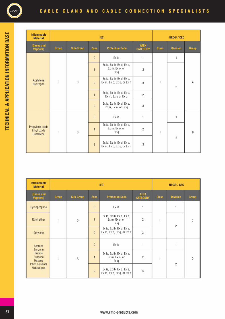
www.cmp-products.com
CMP C A B L E G L A N D A N D C A B L E C O N N E C T I O N S P E C I A L I S T S
InflammableMaterial IEC NEC® / CEC
(Gases andVapours) Group Sub-Group Zone Protection Code
ATEXCATEGORY Class Division Group
AcetyleneHydrogen II C
0 Ex ia 1
I
1
A
1
Ex ia, Ex ib, Ex d, Ex e,Ex m, Ex o, or
Ex q2
22
Ex ia, Ex ib, Ex d, Ex e,Ex m, Ex o, Ex q, or Ex n 3
1Ex ia, Ex ib, Ex d, Ex e,Ex m, Ex o or Ex q 2
2Ex ia, Ex ib, Ex d, Ex e,Ex m, Ex o, or Ex q 3
Propylene oxideEthyl oxideButadiene II B
0 Ex ia 1
I
1
B1
Ex ia, Ex ib, Ex d, Ex e,Ex m, Ex o, or
Ex q2
2
2 Ex ia, Ex ib, Ex d, Ex e,Ex m, Ex o, Ex q, or Ex n 3
InflammableMaterial IEC NEC® / CEC
(Gases andVapours) Group Sub-Group Zone Protection Code
ATEXCATEGORY Class Division Group
Cyclopropane
II B
0 Ex ia 1
I
1
CEthyl ether 1Ex ia, Ex ib, Ex d, Ex e,
Ex m, Ex o, orEx q
2
2
Ethylene 2Ex ia, Ex ib, Ex d, Ex e,Ex m, Ex o, Ex q, or Ex n 3
AcetoneBenzeneButanePropaneHexane
Paint solventsNatural gas
II A
0 Ex ia 1
I
1
D1Ex ia, Ex ib, Ex d, Ex e,
Ex m, Ex o, orEx q
2
2
2 Ex ia, Ex ib, Ex d, Ex e,Ex m, Ex o, Ex q, or Ex n 3
67
TECHNICAL&APPLICATIONINFORM
ATIONBASE
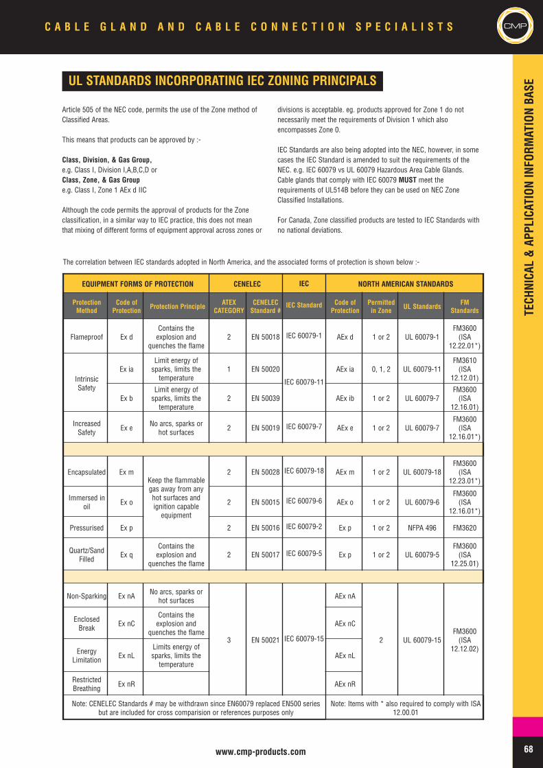
TECHNICAL&APPLICATIONINFORM
ATIONBASE
68www.cmp-products.com
CMPC A B L E G L A N D A N D C A B L E C O N N E C T I O N S P E C I A L I S T S
UL STANDARDS INCORPORATING IEC ZONING PRINCIPALS
Article 505 of the NEC code, permits the use of the Zone method ofClassified Areas.
This means that products can be approved by :-
Class, Division, & Gas Group,e.g. Class I, Division I,A,B,C,D orClass, Zone, & Gas Groupe.g. Class I, Zone 1 AEx d IIC
Although the code permits the approval of products for the Zoneclassification, in a similar way to IEC practice, this does not meanthat mixing of different forms of equipment approval across zones or
divisions is acceptable. eg. products approved for Zone 1 do notnecessarily meet the requirements of Division 1 which alsoencompasses Zone 0.
IEC Standards are also being adopted into the NEC, however, in somecases the IEC Standard is amended to suit the requirements of theNEC. e.g. IEC 60079 vs UL 60079 Hazardous Area Cable Glands.Cable glands that comply with IEC 60079 MUST meet therequirements of UL514B before they can be used on NEC ZoneClassified Installations.
For Canada, Zone classified products are tested to IEC Standards withno national deviations.
EQUIPMENT FORMS OF PROTECTION CENELEC IEC NORTH AMERICAN STANDARDS
ProtectionMethod
Code ofProtection Protection Principle ATEX
CATEGORYCENELECStandard #
IEC Standard Code ofProtection
Permittedin Zone UL Standards FM
Standards
Flameproof Ex dContains theexplosion and
quenches the flame2 EN 50018 IEC 60079-1 AEx d 1 or 2 UL 60079-1
FM3600(ISA
12.22.01*)
IntrinsicSafety
Ex iaLimit energy ofsparks, limits thetemperature
1 EN 50020
IEC 60079-11
AEx ia 0, 1, 2 UL 60079-11FM3610(ISA
12.12.01)
Ex bLimit energy ofsparks, limits thetemperature
2 EN 50039 AEx ib 1 or 2 UL 60079-7FM3600(ISA
12.16.01)
IncreasedSafety Ex e No arcs, sparks or
hot surfaces 2 EN 50019 IEC 60079-7 AEx e 1 or 2 UL 60079-7FM3600(ISA
12.16.01*)
Encapsulated Ex mKeep the flammablegas away from anyhot surfaces andignition capableequipment
2 EN 50028 IEC 60079-18 AEx m 1 or 2 UL 60079-18FM3600(ISA
12.23.01*)
Immersed inoil Ex o 2 EN 50015 IEC 60079-6 AEx o 1 or 2 UL 60079-6
FM3600(ISA
12.16.01*)
Pressurised Ex p 2 EN 50016 IEC 60079-2 Ex p 1 or 2 NFPA 496 FM3620
Quartz/SandFilled Ex q
Contains theexplosion and
quenches the flame2 EN 50017 IEC 60079-5 Ex p 1 or 2 UL 60079-5
FM3600(ISA
12.25.01)
Non-Sparking Ex nA No arcs, sparks orhot surfaces
3 EN 50021 IEC 60079-15
AEx nA
2 UL 60079-15FM3600(ISA
12.12.02)
EnclosedBreak Ex nC
Contains theexplosion and
quenches the flameAEx nC
EnergyLimitation Ex nL
Limits energy ofsparks, limits thetemperature
AEx nL
RestrictedBreathing Ex nR AEx nR
Note: CENELEC Standards # may be withdrawn since EN60079 replaced EN500 seriesbut are included for cross comparision or references purposes only
Note: Items with * also required to comply with ISA12.00.01
The correlation between IEC standards adopted in North America, and the associated forms of protection is shown below :-
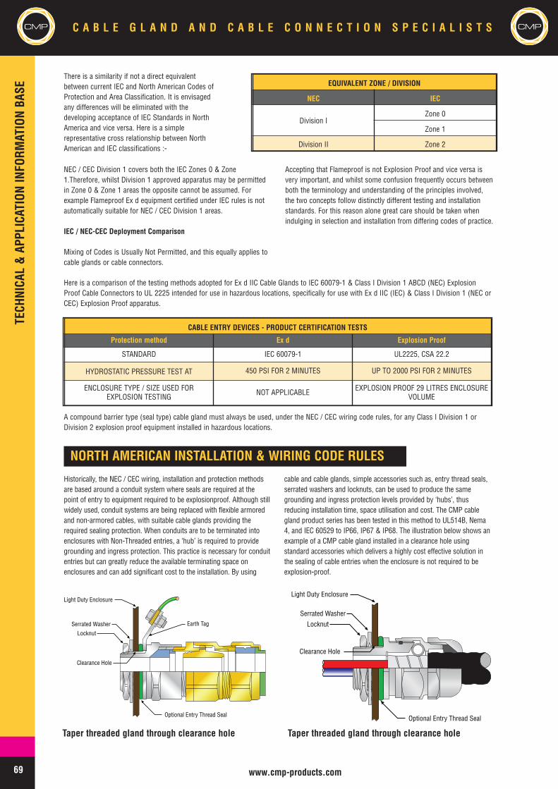
TECHNICAL&APPLICATIONINFORM
ATIONBASE
69 www.cmp-products.com
CMP C A B L E G L A N D A N D C A B L E C O N N E C T I O N S P E C I A L I S T S
68
EQUIVALENT ZONE / DIVISION
NEC IEC
Division IZone 0
Zone 1
Division II Zone 2
NEC / CEC Division 1 covers both the IEC Zones 0 & Zone1.Therefore, whilst Division 1 approved apparatus may be permittedin Zone 0 & Zone 1 areas the opposite cannot be assumed. Forexample Flameproof Ex d equipment certified under IEC rules is notautomatically suitable for NEC / CEC Division 1 areas.
IEC / NEC-CEC Deployment Comparison
Mixing of Codes is Usually Not Permitted, and this equally applies tocable glands or cable connectors.
Accepting that Flameproof is not Explosion Proof and vice versa isvery important, and whilst some confusion frequently occurs betweenboth the terminology and understanding of the principles involved,the two concepts follow distinctly different testing and installationstandards. For this reason alone great care should be taken whenindulging in selection and installation from differing codes of practice.
Here is a comparison of the testing methods adopted for Ex d IIC Cable Glands to IEC 60079-1 & Class I Division 1 ABCD (NEC) ExplosionProof Cable Connectors to UL 2225 intended for use in hazardous locations, specifically for use with Ex d IIC (IEC) & Class I Division 1 (NEC orCEC) Explosion Proof apparatus.
CABLE ENTRY DEVICES - PRODUCT CERTIFICATION TESTS
Protection method Ex d Explosion Proof
STANDARD IEC 60079-1 UL2225, CSA 22.2
HYDROSTATIC PRESSURE TEST AT 450 PSI FOR 2 MINUTES UP TO 2000 PSI FOR 2 MINUTES
ENCLOSURE TYPE / SIZE USED FOREXPLOSION TESTING NOT APPLICABLE EXPLOSION PROOF 29 LITRES ENCLOSURE
VOLUME
CMP
There is a similarity if not a direct equivalentbetween current IEC and North American Codes ofProtection and Area Classification. It is envisagedany differences will be eliminated with thedeveloping acceptance of IEC Standards in NorthAmerica and vice versa. Here is a simplerepresentative cross relationship between NorthAmerican and IEC classifications :-
A compound barrier type (seal type) cable gland must always be used, under the NEC / CEC wiring code rules, for any Class I Division 1 orDivision 2 explosion proof equipment installed in hazardous locations.
NORTH AMERICAN INSTALLATION & WIRING CODE RULES
Historically, the NEC / CEC wiring, installation and protection methodsare based around a conduit system where seals are required at thepoint of entry to equipment required to be explosionproof. Although stillwidely used, conduit systems are being replaced with flexible armoredand non-armored cables, with suitable cable glands providing therequired sealing protection. When conduits are to be terminated intoenclosures with Non-Threaded entries, a ‘hub’ is required to providegrounding and ingress protection. This practice is necessary for conduitentries but can greatly reduce the available terminating space onenclosures and can add significant cost to the installation. By using
cable and cable glands, simple accessories such as, entry thread seals,serrated washers and locknuts, can be used to produce the samegrounding and ingress protection levels provided by ‘hubs’, thusreducing installation time, space utilisation and cost. The CMP cablegland product series has been tested in this method to UL514B, Nema4, and IEC 60529 to IP66, IP67 & IP68. The illustration below shows anexample of a CMP cable gland installed in a clearance hole usingstandard accessories which delivers a highly cost effective solution inthe sealing of cable entries when the enclosure is not required to beexplosion-proof.
Serrated Washer
Light Duty Enclosure
Locknut
Optional Entry Thread Seal
Clearance Hole
Earth Tag
Taper threaded gland through clearance hole
Serrated Washer
Light Duty Enclosure
Locknut
Optional Entry Thread Seal
Clearance Hole
Taper threaded gland through clearance hole
TECHNICAL&APPLICATIONINFORM
ATIONBASE
70www.cmp-products.com
CMPC A B L E G L A N D A N D C A B L E C O N N E C T I O N S P E C I A L I S T S
Cable Wiring Methods
The use of flexible cables in North America has provided industry with awide choice of wiring methods. However, there are differences betweenthe NEC and CEC for cables suitable for use in Hazardous areas andextreme care should be taken during the selection process. i.e. A cabletype may be acceptable for use in Class I Division 1 in Canada, but notin the USA.
It is essential that the wiring method chosen is permitted for use withinthe area classification for the relevant code being utilized.
Cable Wiring Methods - Class I, Division 1 & Zone 1
Complete lists of suitable cable types for use in hazardous areas can befound by consulting the current NEC and CEC handbooks. Additionalinformation for common cable types approved for offshore installationscan be found by consulting section 43 of IEEE Standard 45 and API RPI14F & 14FZ.
As a general rule, cables for use in Class I Division 1 and Zone 1 areasmust be mechanically protected by armor. e.g. MC-HL and Wire BraidArmor (offshore) cables. In Canada, Interlocked armor can be also beused. e.g. Teck 90
Cable Seals, Class I Division 1 & Zone 1
Where cables enter Class I Division 1 or Zone 1 AEx d enclosures, thecable must be sealed at the point of entry with an approved device to UL2225 or CSA 22.2, Class I Division 1 or Zone 1 AEx d, where applicable.The sealing fitting or ‘Barrier’ gland must prevent the passage of gas orvapours through the gland by providing a compound barrier seal aroundeach individual insulated conductor. e.g. CMP TMCX or PX2KX cableconnectors
NEC 2005Article 501.15 (E) (1) Terminations. Cables entering enclosures that arerequired to be explosionproof shall be sealed at the point of entrance.The seal shall comply with 501.15(B)(1)
NEC 2005Article 501.16 (C) (2) Cable Seals. (a) Explosionproof and FlameproofEnclosures. Cables entering enclosures required to be flameproof or
explosionproof shall be sealed at the point of entrance. The seal shallcomply with 505.16(D).
Note; A sealing device certified for Class I Division 1 may be used inClass I Zone 1 AEx d equipment. However, a sealing device certifiedONLY for Class I Zone 1 AEx d CANNOT be used in Class I Division 1equipment. See 501-5(d) of the NEC for further information
Cable Wiring Methods - Class I, Division 2 & Zone 2
Complete lists of suitable cable types for use in hazardous areas can befound by consulting the current NEC and CEC handbooks. Additionalinformation for common cable types approved for offshore installationscan be found by consulting section 43 of IEEE Standard 45 and API RPI14F & 14FZ.
As a general rule, cables permitted and listed for use in Class I Division1 and Zone 1, and listed non-armored cables can be used in Class IDivision 2 and Zone 2 hazardous locations.
e.g. Type TC (Tray Cable), Interlocked Armor cables
Cable Seals, Class I Division 2 & Zone 2
Where cables enter Class I Division 2 enclosures, the cable must besealed if the enclosure contains any arcing or sparking devices or if theenclosure is explosion proof. In such cases a sealing fitting or Barriergland to UL 2225 or CSA 22.2, Class I Division 1 or Division 2 must beused. Where the enclosure does not contain any arcing or sparkingdevices and the enclosure is NOT explosion proof, a cable is notrequired to be sealed at the point of entry. In such cases a listed cablegland or cable connector without compound sealing function may beused. e.g. CMP TMC, T3CDS or C2KX cable connectors.
Similarly for Class I Zone 1 & Zone 2 AEx e enclosures (IncreasedSafety), a non sealing fitting approved for use in this application can beused. e.g. CMP TMC, T3CDS or C2KX cable connectors.
Note : Non ‘Sealing’ type glands are restricted to Division 2 & Zone 2equipment that does not contain an ignition source or to Zone 1 AEx eequipment. If the enclosure is required to be explosion proof, a Sealingfitting must be used.
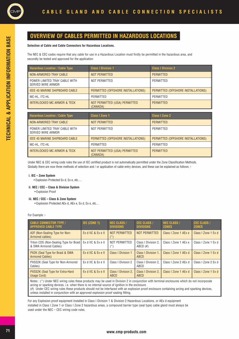
71 www.cmp-products.com
CMP C A B L E G L A N D A N D C A B L E C O N N E C T I O N S P E C I A L I S T STECHNICAL&APPLICATIONINFORM
ATIONBASE
OVERVIEW OF CABLES PERMITTED IN HAZARDOUS LOCATIONSSelection of Cable and Cable Connectors for Hazardous Locations.
The NEC & CEC codes require that any cable for use in a Hazardous Location must firstly be permitted in the hazardous area, andsecondly be tested and approved for the application
Hazardous Location / Cable Type Class I Division 1 Class I Division 2
NON-ARMORED TRAY CABLE NOT PERMITTED PERMITTED
POWER LIMITED TRAY CABLE WITHSERVED WIRE ARMOR
NOT PERMITTED PERMITTED
IEEE 45 MARINE SHIPBOARD CABLE PERMITTED (OFFSHORE INSTALLATIONS) PERMITTED (OFFSHORE INSTALLATIONS)
MC-HL, ITC-HL PERMITTED PERMITTED
INTERLOCKED MC ARMOR & TECK NOT PERMITTED (USA) PERMITTED(CANADA)
PERMITTED
Hazardous Location / Cable Type Class I Zone 1 Class I Zone 2
NON-ARMORED TRAY CABLE NOT PERMITTED PERMITTED
POWER LIMITED TRAY CABLE WITHSERVED WIRE ARMOR
NOT PERMITTED PERMITTED
IEEE 45 MARINE SHIPBOARD CABLE PERMITTED (OFFSHORE INSTALLATIONS) PERMITTED (OFFSHORE INSTALLATIONS)
MC-HL, ITC-HL PERMITTED PERMITTED
INTERLOCKED MC ARMOR & TECK NOT PERMITTED (USA) PERMITTED(CANADA)
PERMITTED
Under NEC & CEC wiring code rules the use of IEC certified product is not automatically permitted under the Zone Classification Methods.Globally there are now three methods of selection and / or application of cable entry devices, and these can be explained as follows :-
i. IEC – Zone System• Explosion Protected Ex d, Ex e, etc….
ii. NEC / CEC – Class & Division System• Explosion Proof
iii. NEC / CEC – Class & Zone System• Explosion Protected AEx d, AEx e, Ex d, Ex e, etc…
For Example :-
CABLE CONNECTOR TYPE /APPROVED CABLE TYPE
IEC (ZONE 1) NEC CLASS /DIVISIONS
CEC CLASS /DIVISIONS
NEC CLASS /ZONES
CEC CLASS /ZONES
A2F (Non-Sealing Type for Non-Armored cables)
Ex d IIC & Ex e II NOT PERMITTED(*)
NOT PERMITTED Class I Zone 1 AEx e Class I Zone 1 Ex d
Triton CDS (Non-Sealing Type for Braid& SWA Armored Cables)
Ex d IIC & Ex e II NOT PERMITTED(*)
Class I Division 2,ABCD (#)
Class I Zone 1 AEx e Class I Zone 1 Ex d
PX2K (Seal Type for Braid & SWAArmored Cables)
Ex d IIC & Ex e II Class I Division 1 Class I Division 1,ABCD
Class I Zone 1 AEx d Class I Zone 1 Ex d
PXSS2K (Seal Type for Non-ArmoredCables)
Ex d IIC & Ex e II Class I Division 2 Class I Division 2,ABCD
Class I Zone 2 AEx d Class I Zone 2 Ex d
PXSS2K (Seal Type for Extra-HardUsage Cord)
Ex d IIC & Ex e II Class I Division 2,ABCD
Class I Division 2,ABCD
Class I Zone 1 AEx d Class I Zone 1 Ex d
Notes : (*) Under NEC wiring rules these products may be used in Division 2 in conjunction with terminal enclosures which do not incorporatearcing or sparking devices, i.e. when there is no internal source of ignition in the enclosure.(#) Under CEC wiring rules these products should not be interfaced with an explosion proof enclosure containing arcing and sparking devices,unless installed in conjunction with an approved explosion proof sealing fitting.
For any Explosion proof equipment installed in Class I Division 1 & Division 2 Hazardous Locations, or AEx d equipmentinstalled in Class I Zone 1 or Class I Zone 2 hazardous areas, a compound barrier type (seal type) cable gland must always beused under the NEC – CEC wiring code rules.
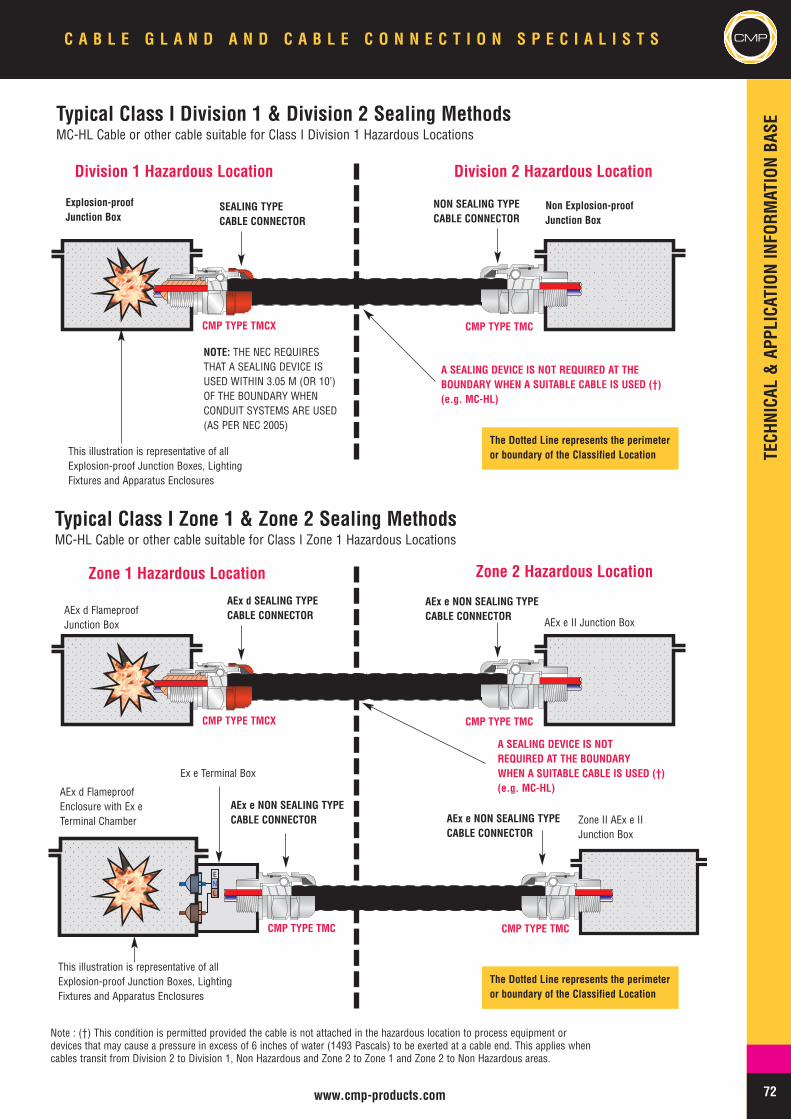
TECHNICAL&APPLICATIONINFORM
ATIONBASE
72
CMPC A B L E G L A N D A N D C A B L E C O N N E C T I O N S P E C I A L I S T S CMP
www.cmp-products.com
Typical Class I Division 1 & Division 2 Sealing MethodsMC-HL Cable or other cable suitable for Class I Division 1 Hazardous Locations
Division 1 Hazardous Location Division 2 Hazardous Location
Explosion-proofJunction Box
SEALING TYPECABLE CONNECTOR
NON SEALING TYPECABLE CONNECTOR
CMP TYPE TMCX CMP TYPE TMC
CMP TYPE TMCX CMP TYPE TMC
LNE
CMP TYPE TMC CMP TYPE TMC
Non Explosion-proofJunction Box
NOTE: THE NEC REQUIRESTHAT A SEALING DEVICE ISUSED WITHIN 3.05 M (OR 10’)OF THE BOUNDARY WHENCONDUIT SYSTEMS ARE USED(AS PER NEC 2005)
A SEALING DEVICE IS NOT REQUIRED AT THEBOUNDARY WHEN A SUITABLE CABLE IS USED (†)(e.g. MC-HL)
This illustration is representative of allExplosion-proof Junction Boxes, LightingFixtures and Apparatus Enclosures
The Dotted Line represents the perimeteror boundary of the Classified Location
The Dotted Line represents the perimeteror boundary of the Classified Location
Typical Class I Zone 1 & Zone 2 Sealing MethodsMC-HL Cable or other cable suitable for Class I Zone 1 Hazardous Locations
Zone 1 Hazardous Location Zone 2 Hazardous Location
AEx d SEALING TYPECABLE CONNECTOR
AEx e NON SEALING TYPECABLE CONNECTORAEx d Flameproof
Junction Box
A SEALING DEVICE IS NOTREQUIRED AT THE BOUNDARYWHEN A SUITABLE CABLE IS USED (†)(e.g. MC-HL)
This illustration is representative of allExplosion-proof Junction Boxes, LightingFixtures and Apparatus Enclosures
AEx e II Junction Box
AEx d FlameproofEnclosure with Ex eTerminal Chamber
Ex e Terminal Box
AEx e NON SEALING TYPECABLE CONNECTOR AEx e NON SEALING TYPE
CABLE CONNECTORZone II AEx e IIJunction Box
Note : (†) This condition is permitted provided the cable is not attached in the hazardous location to process equipment ordevices that may cause a pressure in excess of 6 inches of water (1493 Pascals) to be exerted at a cable end. This applies whencables transit from Division 2 to Division 1, Non Hazardous and Zone 2 to Zone 1 and Zone 2 to Non Hazardous areas.
73 www.cmp-products.com
CMP C A B L E G L A N D A N D C A B L E C O N N E C T I O N S P E C I A L I S T STECHNICAL&APPLICATIONINFORM
ATIONBASE
NOTE: THE NEC REQUIRESTHAT A SEALING DEVICE ISUSED WITHIN 3.05 M (OR 10’)OF THE BOUNDARY WHENCONDUIT SYSTEMS ARE USED(AS PER NEC 2005)
Typical Class I Zone 1 & Zone 2 Sealing MethodsMC-HL Cable or other cable suitable for Class I Zone 1 Hazardous Locations
Zone 2 Hazardous Location Non-Hazardous Location
AEx d SEALING TYPECABLE CONNECTOR
AEx e NON SEALING TYPECABLE CONNECTOR
AEx d FlameproofJunction Box
CMPTYPE TMCX
A SEALING DEVICE IS NOTREQUIRED AT THE BOUNDARYWHEN A SUITABLE CABLE ISUSED (†) (e.g. MC-HL)
This illustration is representative of allExplosion-proof Junction Boxes, LightingFixtures and Apparatus Enclosures
CMPTYPE TMC
Non Hazardous AreaJunction Box
NON SEALING TYPE CABLECONNECTOR
CMPTYPE TMC
AEx e IIJunction Box
CMPTYPE TMCX
CMPTYPE TMC
CMPTYPE TMC
Typical Class I Zone 1 & Zone 2 Sealing MethodsMC-HL Cable or other cable suitable for Class I Zone 1 Hazardous Locations
Zone 2 Hazardous Location Non-Hazardous Location
AEx e NON SEALING TYPECABLE CONNECTOR
SEALING DEVICENOT REQUIRED ATBOUNDARY WHENCABLE IS USED (†)
Non Hazardous AreaJunction Box
NON SEALING TYPE CABLECONNECTOR
AEx e IIJunction Box
The Dotted Line represents the perimeteror boundary of the Classified Location
The Dotted Line represents the perimeteror boundary of the Classified Location
Note : (†) This condition is permitted provided the cable is not attached in the hazardous location to process equipment ordevices that may cause a pressure in excess of 6 inches of water (1493 Pascals) to be exerted at a cable end. This applies whencables transit from Division 2 to Division 1, Non Hazardous and Zone 2 to Zone 1 and Zone 2 to Non Hazardous areas.
CMPTYPE TMCX
CMPTYPE TMC
CMPTYPE TMC
CMPTYPE TMCX
74www.cmp-products.com
CMPC A B L E G L A N D A N D C A B L E C O N N E C T I O N S P E C I A L I S T S
TECHNICAL&APPLICATIONINFORM
ATIONBASE
CMP
Division 2 Hazardous Location Non-Hazardous Location
Explosion-proofJunction Box
SEALING TYPECABLE CONNECTOR
NON SEALING TYPECABLE CONNECTOR
NON SEALING TYPECABLE CONNECTOR
Non Explosion-proofJunction Box
NOTE: THE NEC REQUIRESTHAT A SEALING DEVICE ISUSED WITHIN 3.05 M (OR 10’)OF THE BOUNDARY WHENCONDUIT SYSTEMS ARE USED(AS PER NEC 2005)
This illustration is representative of allExplosion-proof Junction Boxes, LightingFixtures and Apparatus Enclosures
Non Explosion-proofJunction Box
Typical Class I Division 1 & Division 2 Sealing MethodsMC-HL Cable or other cable suitable for Class I Division 1 Hazardous Locations
A SEALING DEVICE IS NOTREQUIRED AT THEBOUNDARY WHEN ASUITABLE CABLE IS USED (†)(e.g. MC-HL)
The Dotted Line represents the perimeteror boundary of the Classified Location
Note : (†) This condition is permitted provided the cable is not attached in the hazardous location to process equipment ordevices that may cause a pressure in excess of 6 inches of water (1493 Pascals) to be exerted at a cable end. This applies whencables transit from Division 2 to Division 1, Non Hazardous and Zone 2 to Zone 1 and Zone 2 to Non Hazardous areas.

INDUSTRIALCABLEGLANDS
CMPCMPINDU
STRIAL
CABL
EGL
ANDS
C A B L E G L A N D A N D C A B L E C O N N E C T I O N S P E C I A L I S T S
75

INDU
STRIAL
CABL
EGL
ANDS
CMP
APPLICATION
The CMP Products range of industrial cableglands embraces products used in a wide anddiverse variety of market sectors, in conjunctionwith virtually every kind of industrial cableinstallation. With a wealth of experience interminating all types of armoured andunarmoured cables CMP has discovered thatwhen it comes to such critical installations,quality and reliability really do count.
PRODUCTS
CMP cable gland options for all types of cablesare available in a wide range of sizes and aresupplied in a variety of thread forms. Cableglands are available in various materialsincluding Brass, Electroless Nickel Plated Brass,Aluminium and Stainless Steel. Significantly thebrass grade used in the production of all CMPbrass cable glands is CuZn39Pb3 (CW614N) toEN12168, which is a highly desirable feature butquite often overlooked.
SPECIFICATIONS & APPROVALS
CMP Products designs and manufactures cableglands and accessories conforming to theprevailing industry standards includingEN50262:1999 and the more onerousBS6121:Part 1:1989. CMP Products holds ahost of internationally recognised approvals,and its product range is manufactured under a3rd Party approved Quality ManagementsSystem conforming to ISO 9001 : 2000.
CMP
76
C A B L E G L A N D A N D C A B L E C O N N E C T I O N S P E C I A L I S T S
CableGlandSize
EntryThread‘C’
MinimumThreadLength‘E’
CableBeddingDiameter
‘A’
OverallCable
Diameter‘B’
Armour RangeAcrossFlats‘D’
AcrossCorners‘D’
NominalProtrusionLength‘F’
OrderingReference(BrassMetric)
PVCShroud
Reference*
CableGlandWeight(Kgs)
Max Max Min Max
20S M20 10.0 11.7 16.1 0.9 1.25 22.0 24.0 18.0 20SBW1AA PVC02 0.09
20 M20 10.0 14.0 21.1 0.9 1.25 28.0 30.0 22.0 20BW1AA PVC05 0.10
25 M25 10.0 20.0 27.4 1.25 1.60 33.6 36.0 26.0 25BW1AA PVC07 0.15
32 M32 10.0 26.3 34.4 1.6 2.00 41.0 44.5 28.0 32BW1AA PVC10 0.20
40 M40 10.0 32.2 42.4 1.6 2.00 50.0 56.3 30.0 40BW1AA PVC13 0.36
50S M50 15.0 38.2 50.1 2.0 2.50 57.1 63.4 30.0 50SBW1AA PVC16 0.48
50 M50 15.0 44.1 55.7 2.0 2.50 61.0 72.1 32.0 50BW1AA PVC19 0.42
63S M63 15.0 50.0 62.4 2.5 2.50 75.0 83.0 38.0 63SBW1AA PVC22 0.80
63 M63 15.0 56.0 68.2 2.5 2.50 80.0 88.7 38.0 63BW1AA PVC24 0.85
75S M75 15.0 62.0 76.8 2.5 2.50 90.0 99.8 40.0 75SBW1AA PVC27 1.30
75 M75 15.0 75.0 82.9 2.5 3.15 95.0 105.3 40.0 75BW1AA PVC29 1.60
All dimensions in millimetres
TECHNICAL DATA
Type BW
Design Specification BS 6121: Part 1: 2005
GOST R Certificate Number POCC GB. 05.H00110
GOST K Certificate Number KZ7500052.05.01.00063
RoK Permit for Use Number 08-067693
Lloyds Approval Number 01/00171
ABS Approval Number 01-LD 234401-PDA
Standard Gland Material Brass
Alternative Gland Material Electroless Nickel Plated Brass, Stainless Steel, Aluminium
Cable Type Single Wire Armour (SWA), Aluminium Wire Armour (AWA)
Armour Clamping Two Part Armour Lock
Optional Accessories Adaptor/Reducer, Earth Tag, Locknut, Serrated Washer, Shroud
Gland Kits Available
Cable Gland Kit for use with all types of SWA cable, including 2 Brass Glands, 2Steel Locknuts, 2 Brass Earth Tags and 2 PVC Shrouds for sizes up to andincluding 32mm. For sizes 40mm and above each kit includes 1 of eachcomponent.
CMPINDU
STRIAL
CABL
EGL
ANDS
www.cmp-products.com
CMP BW type brass indoor cable gland for use with all types of Single Wire Armour (SWA) cableproviding mechanical cable retention and electrical continuity via armour wire termination. The CMPBW range of industrial cable glands is designed and tested to BS6121:2005, and is produced fromBrass grade CuZn39Pb3 (CW614N) to EN12168
BW Industrial Cable GlandBW CABLE GLAND
AA
CC
EE
BB
DD
FF
Cable Gland Selection Table
Note: *LSF Shrouds also available on request.
LLU
C A B L E G L A N D A N D C A B L E C O N N E C T I O N S P E C I A L I S T SCMP
77
Max Max
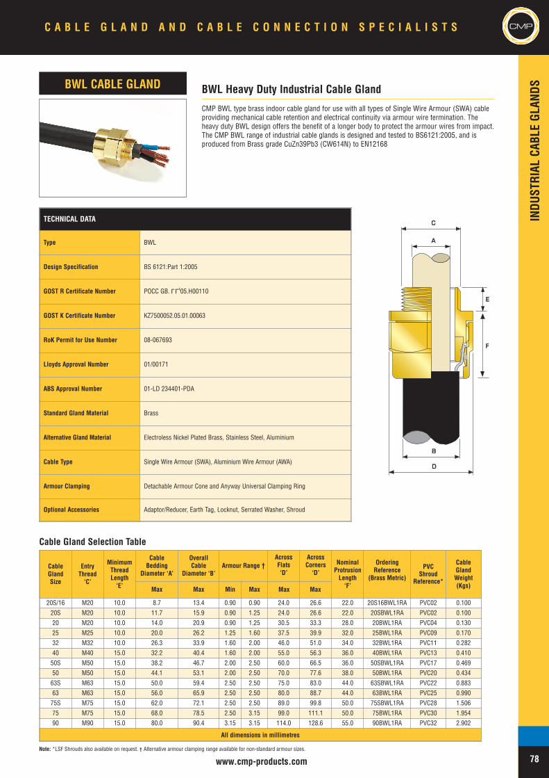
INDU
STRIAL
CABL
EGL
ANDS
TECHNICAL DATA
Type BWL
Design Specification BS 6121:Part 1:2005
GOST R Certificate Number POCC GB. 05.H00110
GOST K Certificate Number KZ7500052.05.01.00063
RoK Permit for Use Number 08-067693
Lloyds Approval Number 01/00171
ABS Approval Number 01-LD 234401-PDA
Standard Gland Material Brass
Alternative Gland Material Electroless Nickel Plated Brass, Stainless Steel, Aluminium
Cable Type Single Wire Armour (SWA), Aluminium Wire Armour (AWA)
Armour Clamping Detachable Armour Cone and Anyway Universal Clamping Ring
Optional Accessories Adaptor/Reducer, Earth Tag, Locknut, Serrated Washer, Shroud
LLU
CMP BWL type brass indoor cable gland for use with all types of Single Wire Armour (SWA) cableproviding mechanical cable retention and electrical continuity via armour wire termination. Theheavy duty BWL design offers the benefit of a longer body to protect the armour wires from impact.The CMP BWL range of industrial cable glands is designed and tested to BS6121:2005, and isproduced from Brass grade CuZn39Pb3 (CW614N) to EN12168
BWL Heavy Duty Industrial Cable GlandBWL CABLE GLAND
AA
CC
EE
BB
DD
FF
Cable Gland Selection Table
CableGlandSize
EntryThread‘C’
MinimumThreadLength‘E’
CableBedding
Diameter ‘A’
OverallCable
Diameter ‘B’Armour Range †
AcrossFlats‘D’
AcrossCorners‘D’
NominalProtrusionLength‘F’
OrderingReference
(Brass Metric)
PVCShroud
Reference*
CableGlandWeight(Kgs)Max Max Min Max
20S/16 M20 10.0 8.7 13.4 0.90 0.90 24.0 26.6 22.0 20S16BWL1RA PVC02 0.10020S M20 10.0 11.7 15.9 0.90 1.25 24.0 26.6 22.0 20SBWL1RA PVC02 0.10020 M20 10.0 14.0 20.9 0.90 1.25 30.5 33.3 28.0 20BWL1RA PVC04 0.13025 M25 10.0 20.0 26.2 1.25 1.60 37.5 39.9 32.0 25BWL1RA PVC09 0.17032 M32 10.0 26.3 33.9 1.60 2.00 46.0 51.0 34.0 32BWL1RA PVC11 0.28240 M40 15.0 32.2 40.4 1.60 2.00 55.0 56.3 36.0 40BWL1RA PVC13 0.41050S M50 15.0 38.2 46.7 2.00 2.50 60.0 66.5 36.0 50SBWL1RA PVC17 0.46950 M50 15.0 44.1 53.1 2.00 2.50 70.0 77.6 38.0 50BWL1RA PVC20 0.43463S M63 15.0 50.0 59.4 2.50 2.50 75.0 83.0 44.0 63SBWL1RA PVC22 0.88363 M63 15.0 56.0 65.9 2.50 2.50 80.0 88.7 44.0 63BWL1RA PVC25 0.99075S M75 15.0 62.0 72.1 2.50 2.50 89.0 99.8 50.0 75SBWL1RA PVC28 1.50675 M75 15.0 68.0 78.5 2.50 3.15 99.0 111.1 50.0 75BWL1RA PVC30 1.95490 M90 15.0 80.0 90.4 3.15 3.15 114.0 128.6 55.0 90BWL1RA PVC32 2.902
All dimensions in millimetres
www.cmp-products.com
CMP
Note: *LSF Shrouds also available on request. † Alternative armour clamping range available for non-standard armour sizes.
C A B L E G L A N D A N D C A B L E C O N N E C T I O N S P E C I A L I S T S CMP
78
Max Max

CableGlandSize
AvailableEntry
Threads‘C’
MinimumThreadLength‘E’
CableBeddingDiameter
‘A’
OverallCable
Diameter‘B’
Armour Range † AcrossFlats‘D’
AcrossCorners‘D’
NominalProtrusionLength‘F’
OrderingReference
(Brass Metric)#
PVCShroud
Reference*
CableGlandWeight(Kgs)Grooved Cone Stepped Cone
Metric Max Min Max Min Max Min Max20S/16 M20 10.0 8.7 6.1 11.5 0.0 1.0 0.90 1.00 30.5 33.3 47.0 20S16C2KGP1RA PVC04 0.13220S M20 10.0 11.7 9.5 15.9 0.0 1.0 0.90 1.25 30.5 33.3 47.0 20SC2KGP1RA PVC04 0.13220 M20 10.0 14.0 12.5 20.9 0.0 1.0 0.90 1.25 30.5 33.3 50.0 20C2KGP1RA PVC06 0.19425S M25 10.0 14.0 14.0 22.0 0.0 1.0 1.25 1.60 36.0 40.0 55.0 25SC2KGP1RA PVC09 0.30625 M25 10.0 20.0 18.2 26.2 0.0 1.0 1.25 1.60 36.0 40.0 55.0 25C2KGP1RA PVC09 0.30632 M32 10.0 26.3 23.7 33.9 0.0 1.0 1.60 2.00 46.0 51.0 58.0 32C2KGP1RA PVC11 0.46840 M40 10.0 32.2 27.9 40.4 0.0 1.0 1.60 2.00 55.0 61.0 58.0 40C2KGP1RA PVC15 0.67850S M50 10.0 38.2 35.2 46.7 0.0 1.0 2.00 2.50 60.0 66.5 58.0 50SC2KGP1RA PVC18 0.75050 M50 10.0 44.1 40.4 53.1 0.0 1.0 2.00 2.50 70.1 78.6 60.0 50C2KGP1RA PVC21 1.04463S M63 10.0 50.0 45.6 59.4 0.0 1.0 2.00 2.50 75.0 83.2 70.0 63SC2KGP1RA PVC23 1.07463 M63 10.0 56.0 54.6 65.9 0.0 1.0 2.00 2.50 80.0 89.0 70.0 63C2KGP1RA PVC25 1.28075S M75 15.0 62.0 59.0 72.1 0.0 1.0 2.00 2.50 90.0 99.8 80.0 75SC2KGP1RA PVC28 1.86075 M75 15.0 68.0 66.7 78.5 0.0 1.0 2.00 2.50 100.0 111.0 82.0 75C2KGP1RA PVC30 2.55090 M90 15.0 80.0 76.2 90.4 0.0 1.6 3.15 3.15 115.0 127.5 96.0 90C2KGP1RA PVC32 3.650100 M100 15.0 91.0 89.1 101.5 0.0 1.6 3.15 4.00 123.0 136.0 106.0 100C2KGP1RA 150/50HST 4.200115 M115 15.0 98.0 101.3 110.3 0.0 1.6 3.15 4.00 133.4 147.8 115.0 115C2KGP1RA 180/60HST 4.750130 M130 15.0 115.0 114.0 123.3 0.0 1.6 3.15 4.00 146.1 152.4 125.0 130C2KGP1RA 180/60HST 5.330
All dimensions in millimetres
CMPINDU
STRIAL
CABL
EGL
ANDS
www.cmp-products.com
CMP C2KGP type brass indoor and outdoor cable gland for use with all types of Single Wire Armour(SWA), Wire Braid Armour, Strip Armour, Pliable Wire Armour & Steel Tape Armour (STA) cable,providing environmental seal on the cable outer sheath and additional deluge seal meeting the testrequirements of DTS01:91. The cable gland also provides mechanical cable retention and electricalcontinuity via armour termination. A reversible armour cone and AnyWay universal clamping ringarrangement allows the cable to be easily disconnected from the equipment, for maintenance andchange out etc. This feature also facilitates remote make off procedures when the termination is to beconducted in confined spaces or in areas of restricted access.
The CMP C2KGP range of industrial cable glands is designed and tested to BS 6121:Part 1:1989, meetsor surpasses the requirements of EN 50262 :1999, and is produced from Brass grade CuZn39Pb3(CW614N) to EN12168
C2KGP Industrial Cable GlandC2KGP CABLE GLAND
AA
BB
DD
CC
EE
FF
Cable Gland Selection Table
Note: *LSF Shrouds also available on request. † Alternative armour clamping range available for non-standard armour sizes. Marine approvals including Lloyds, DNV & ABS are also available from CMP Products.
TECHNICAL DATAType C2KGP
Design Specification BS 6121:Part 1:1989, EN 50262:1999
EN 50262 Mechanical Classifications Retention = Class B, Impact = Level 8,
EN 50262 Electrical Classifications Category A without use of an Earth Tag and Category B with an Earth Tag.
GOST R Certificate Number POCC GB. 05.H00110
GOST K Certificate Number KZ7500052.05.01.00063
RoK Permit for Use Number 08-067693
Continuous Operating Temperature -60°C to +150°C
Ingress Protection Rating IP66, IP67, IP68
Ingress Protection Document 5046/C549H
Deluge Protection Compliance DTS01 : 91
Deluge Protection Document 5046/C549H-D
Standard Gland Material Brass
Alternative Gland Material Electroless Nickel Plated Brass, Stainless Steel, Aluminium
Seal Material CMP Formulated Thermoplastic Elastomer
Cable TypeSingle Wire Armour (SWA), Aluminium Wire Armour (AWA), Steel Tape Armour(STA), Aluminium Strip Armour (ASA), Wire Braid Armour, Screened Flexible WireBraid (e.g. CY / SY)
Armour Clamping Reversible Armour Cone & AnyWay Universal Clamping Ring
Sealing Technique Unique CMP "LRS" ™ Outer Seal (Load Retention Seal)
Sealing Area(s) Cable Outer Sheath
Optional Accessories Adaptor/Reducer, Earth Tag, Entry Thread Seal, Locknut, Serrated Washer,Shroud
LLU
C A B L E G L A N D A N D C A B L E C O N N E C T I O N S P E C I A L I S T S
79
CMP
Max Max
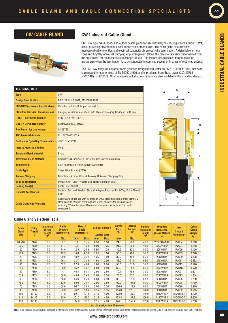
INDU
STRIAL
CABL
EGL
ANDS
www.cmp-products.com
CMP
CMP CW type brass indoor and outdoor cable gland for use with all types of Single Wire Armour (SWA)cable, providing environmental seal on the cable outer sheath. The cable gland also providesmechanical cable retention and electrical continuity via armour wire termination. A detachable armourcone and AnyWay universal clamping ring arrangement allows the cable to be easily disconnected fromthe equipment, for maintenance and change out etc. This feature also facilitates remote make offprocedures when the termination is to be conducted in confined spaces or in areas of restricted access.
The CMP CW range of industrial cable glands is designed and tested to BS 6121:Part 1:1989, meets orsurpasses the requirements of EN 50262 :1999, and is produced from Brass grade CuZn39Pb3(CW614N) to EN12168. Other materials including Aluminium are also available in this standard design.
CW Industrial Cable GlandCW CABLE GLAND
AA
CC
EE
BB
DD
FF
Cable Gland Selection Table
TECHNICAL DATA
Type CW
Design Specification BS 6121:Part 1:1989, EN 50262:1999
EN 50262 Mechanical Classifications Retention = Class B, Impact = Level 8,
EN 50262 Electrical Classifications Category A without use of an Earth Tag and Category B with an Earth Tag.
GOST R Certificate Number POCC GB. 05.H00110
GOST K Certificate Number KZ7500052.05.01.00063
RoK Permit for Use Number 08-067693
ABS Approval Number 01-LD 234401-PDA
Continuous Operating Temperature -60°C to +150°C
Ingress Protection Rating IP66
Standard Gland Material Brass
Alternative Gland Material Electroless Nickel Plated Brass, Stainless Steel, Aluminium
Seal Material CMP Formulated Thermoplastic Elastomer
Cable Type Single Wire Armour (SWA)
Armour Clamping Detachable Armour Cone & AnyWay Universal Clamping Ring
Sealing Technique Unique CMP "LRS" ™ Outer Seal (Load Retention Seal)
Sealing Area(s) Cable Outer Sheath
Optional Accessories Locknut, Serrated Washer, Shroud, Adaptor/Reducer, Earth Tag, Entry ThreadSeal
Cable Gland Kits Available
Cable Gland kit for use with all types of SWA cable including 2 brass glands, 2steel locknuts, 2 brass earth tags and 2 PVC shrouds for sizes up to andincluding 32mm. For sizes 40mm and above each kit includes 1 of eachcomponent.
LLU
CableGlandSize
EntryThread‘C’
MinimumThreadLength‘E’
CableBedding
Diameter ‘A’
OverallCable
Diameter ‘B’
Armour Range †AcrossFlats‘D’
AcrossCorners‘D’
NominalProtrusionLength‘F’
OrderingReference
(Brass Metric)#
PVCShroud
Reference*
CableGlandWeight(Kgs)Stepped Cone
Max Min Max Min Max20S/16 M20 10.0 8.7 6.1 11.5 0.90 1.00 24.0 26.6 43.0 20S16CW1RA PVC04 0.11820S M20 10.0 11.7 9.5 15.9 0.90 1.25 24.0 26.6 43.0 20SCW1RA PVC04 0.11820 M20 10.0 14.0 12.5 20.9 0.90 1.25 30.5 33.3 50.0 20CW1RA PVC06 0.15925S M25 10.0 19.9 14.0 22.0 1.25 1.60 36.0 40.0 55.0 25SCW1RA PVC09 0.22825 M25 10.0 20.0 18.2 26.2 1.25 1.60 36.0 40.0 55.0 25CW1RA PVC09 0.22832 M32 10.0 26.3 23.7 33.9 1.60 2.00 46.0 51.0 55.0 32CW1RA PVC11 0.36240 M40 15.0 32.2 27.9 40.4 1.60 2.00 55.0 61.0 55.0 40CW1RA PVC15 0.52050S M50 15.0 38.2 35.2 46.7 2.00 2.50 60.0 66.5 56.0 50SCW1RA PVC18 0.57950 M50 15.0 44.1 40.4 53.1 2.00 2.50 70.1 78.6 70.0 50CW1RA PVC21 0.60163S M63 15.0 50.0 45.6 59.4 2.00 2.50 75.0 83.2 70.0 63SCW1RA PVC23 1.05463 M63 15.0 56.0 54.6 65.9 2.00 2.50 80.0 89.0 80.0 63CW1RA PVC25 1.20075S M75 15.0 62.0 59.0 72.1 2.00 2.50 90.0 101.6 81.0 75SCW1RA PVC28 1.77975 M75 15.0 68.0 66.7 78.5 2.00 2.50 100.0 111.1 96.0 75CW1RA PVC30 2.37090 M90 15.0 80.0 76.2 90.4 3.15 3.15 114.0 128.6 120.0 90CW1RA PVC32 3.515100 M100 15.0 91.0 89.1 101.5 3.15 4.00 123.0 136.0 140.0 100CW1RA 150/50HST 4.100115 M115 15.0 98.0 101.3 110.3 3.15 4.00 133.4 147.8 160.0 115CW1RA 180/60HST 4.600130 M130 15.0 115.0 114.0 123.3 3.15 4.00 146.1 152.4 169.0 130CW1RA 180/60HST 5.200
All dimensions in millimetres
Note: *LSF Shrouds also available on request. † Alternative armour clamping range available for non-standard armour sizes. Marine approvals including Lloyds, DNV & ABS are also available from CMP Products.
C A B L E G L A N D A N D C A B L E C O N N E C T I O N S P E C I A L I S T S CMP
80
Max Max
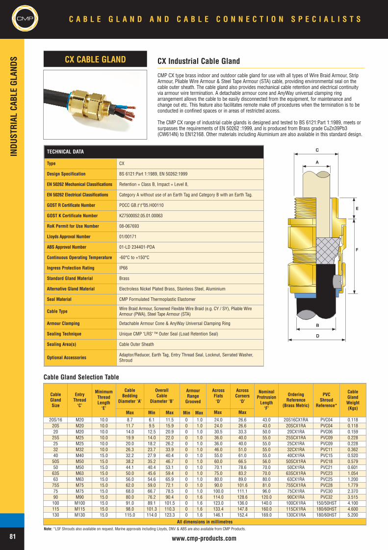
CMPINDU
STRIAL
CABL
EGL
ANDS
www.cmp-products.com
AA
CC
EE
BB
DD
FF
Cable Gland Selection Table
TECHNICAL DATA
Type CX
Design Specification BS 6121:Part 1:1989, EN 50262:1999
EN 50262 Mechanical Classifications Retention = Class B, Impact = Level 8,
EN 50262 Electrical Classifications Category A without use of an Earth Tag and Category B with an Earth Tag.
GOST R Certificate Number POCC GB. 05.H00110
GOST K Certificate Number KZ7500052.05.01.00063
RoK Permit for Use Number 08-067693
Lloyds Approval Number 01/00171
ABS Approval Number 01-LD 234401-PDA
Continuous Operating Temperature -60°C to +150°C
Ingress Protection Rating IP66
Standard Gland Material Brass
Alternative Gland Material Electroless Nickel Plated Brass, Stainless Steel, Aluminium
Seal Material CMP Formulated Thermoplastic Elastomer
Cable Type Wire Braid Armour, Screened Flexible Wire Braid (e.g. CY / SY), Pliable WireArmour (PWA), Steel Tape Armour (STA)
Armour Clamping Detachable Armour Cone & AnyWay Universal Clamping Ring
Sealing Technique Unique CMP "LRS" ™ Outer Seal (Load Retention Seal)
Sealing Area(s) Cable Outer Sheath
Optional Accessories Adaptor/Reducer, Earth Tag, Entry Thread Seal, Locknut, Serrated Washer,Shroud
LLU
CX Industrial Cable GlandCX CABLE GLAND
CMP CX type brass indoor and outdoor cable gland for use with all types of Wire Braid Armour, StripArmour, Pliable Wire Armour & Steel Tape Armour (STA) cable, providing environmental seal on thecable outer sheath. The cable gland also provides mechanical cable retention and electrical continuityvia armour wire termination. A detachable armour cone and AnyWay universal clamping ringarrangement allows the cable to be easily disconnected from the equipment, for maintenance andchange out etc. This feature also facilitates remote make off procedures when the termination is to beconducted in confined spaces or in areas of restricted access.
The CMP CX range of industrial cable glands is designed and tested to BS 6121:Part 1:1989, meets orsurpasses the requirements of EN 50262 :1999, and is produced from Brass grade CuZn39Pb3(CW614N) to EN12168. Other materials including Aluminium are also available in this standard design.
C A B L E G L A N D A N D C A B L E C O N N E C T I O N S P E C I A L I S T S
81
CMP
CableGlandSize
EntryThread‘C’
MinimumThreadLength‘E’
CableBedding
Diameter ‘A’
OverallCable
Diameter ‘B’
ArmourRangeGrooved
AcrossFlats‘D’
AcrossCorners‘D’
NominalProtrusionLength‘F’
OrderingReference
(Brass Metric)
PVCShroud
Reference*
CableGlandWeight(Kgs)
Max Min Max
20S/16 M20 10.0 8.7 6.1 11.5 0 1.0 24.0 26.6 43.0 20S16CX1RA PVC04 0.11820S M20 10.0 11.7 9.5 15.9 0 1.0 24.0 26.6 43.0 20SCX1RA PVC04 0.11820 M20 10.0 14.0 12.5 20.9 0 1.0 30.5 33.3 50.0 20CX1RA PVC06 0.15925S M25 10.0 19.9 14.0 22.0 0 1.0 36.0 40.0 55.0 25SCX1RA PVC09 0.22825 M25 10.0 20.0 18.2 26.2 0 1.0 36.0 40.0 55.0 25CX1RA PVC09 0.22832 M32 10.0 26.3 23.7 33.9 0 1.0 46.0 51.0 55.0 32CX1RA PVC11 0.36240 M40 15.0 32.2 27.9 40.4 0 1.0 55.0 61.0 55.0 40CX1RA PVC15 0.52050S M50 15.0 38.2 35.2 46.7 0 1.0 60.0 66.5 56.0 50SCX1RA PVC18 0.57950 M50 15.0 44.1 40.4 53.1 0 1.0 70.1 78.6 70.0 50CX1RA PVC21 0.60163S M63 15.0 50.0 45.6 59.4 0 1.0 75.0 83.2 70.0 63SCX1RA PVC23 1.05463 M63 15.0 56.0 54.6 65.9 0 1.0 80.0 89.0 80.0 63CX1RA PVC25 1.20075S M75 15.0 62.0 59.0 72.1 0 1.0 90.0 101.6 81.0 75SCX1RA PVC28 1.77975 M75 15.0 68.0 66.7 78.5 0 1.0 100.0 111.1 96.0 75CX1RA PVC30 2.37090 M90 15.0 80.0 76.2 90.4 0 1.6 114.0 128.6 120.0 90CX1RA PVC32 3.515100 M100 15.0 91.0 89.1 101.5 0 1.6 123.0 136.0 140.0 100CX1RA 150/50HST 4.100115 M115 15.0 98.0 101.3 110.3 0 1.6 133.4 147.8 160.0 115CX1RA 180/60HST 4.600130 M130 15.0 115.0 114.0 123.3 0 1.6 146.1 152.4 169.0 130CX1RA 180/60HST 5.200
All dimensions in millimetresNote: *LSF Shrouds also available on request. Marine approvals including Lloyds, DNV & ABS are also available from CMP Products.
Min Max Max Max
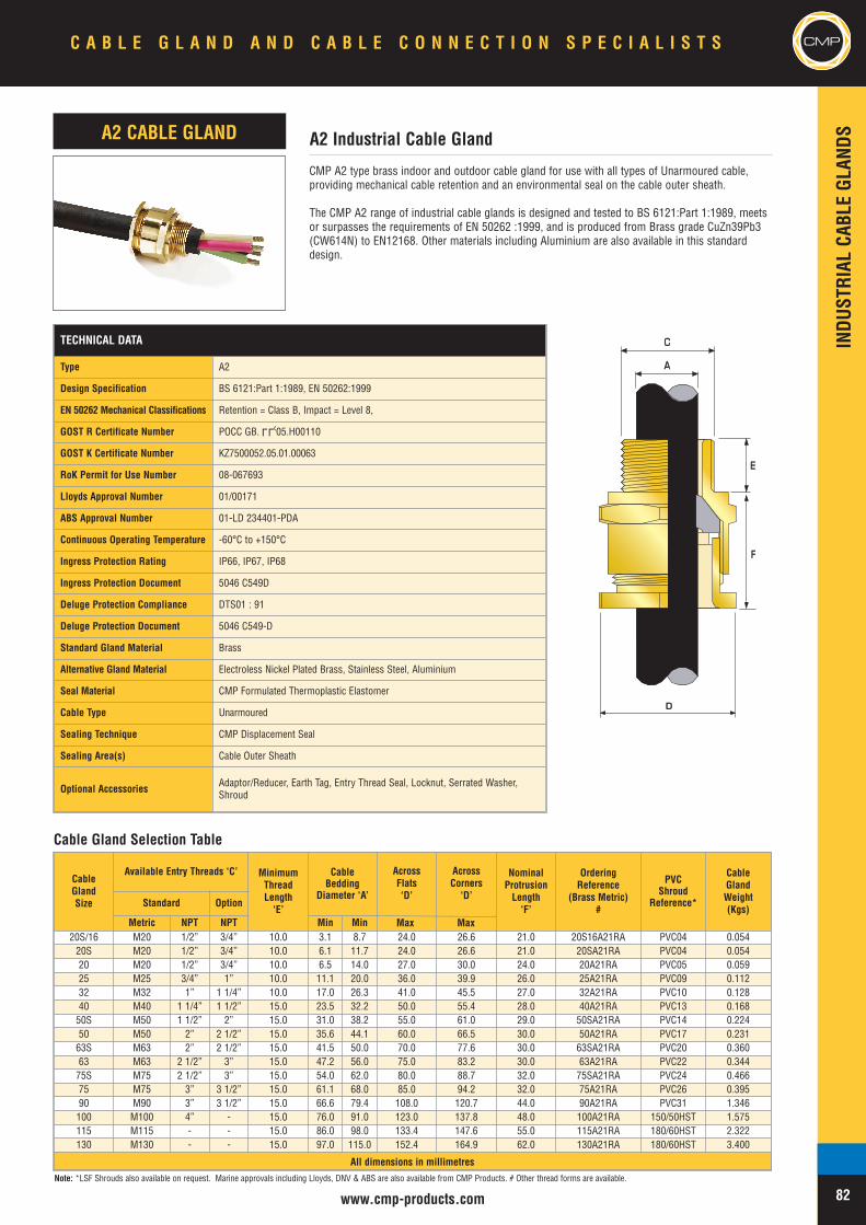
INDU
STRIAL
CABL
EGL
ANDS
www.cmp-products.com
CMP
CMP A2 type brass indoor and outdoor cable gland for use with all types of Unarmoured cable,providing mechanical cable retention and an environmental seal on the cable outer sheath.
The CMP A2 range of industrial cable glands is designed and tested to BS 6121:Part 1:1989, meetsor surpasses the requirements of EN 50262 :1999, and is produced from Brass grade CuZn39Pb3(CW614N) to EN12168. Other materials including Aluminium are also available in this standarddesign.
A2 Industrial Cable GlandA2 CABLE GLAND
DD
AA
CC
EE
FF
Cable Gland Selection Table
TECHNICAL DATA
Type A2
Design Specification BS 6121:Part 1:1989, EN 50262:1999
EN 50262 Mechanical Classifications Retention = Class B, Impact = Level 8,
GOST R Certificate Number POCC GB. 05.H00110
GOST K Certificate Number KZ7500052.05.01.00063
RoK Permit for Use Number 08-067693
Lloyds Approval Number 01/00171
ABS Approval Number 01-LD 234401-PDA
Continuous Operating Temperature -60°C to +150°C
Ingress Protection Rating IP66, IP67, IP68
Ingress Protection Document 5046 C549D
Deluge Protection Compliance DTS01 : 91
Deluge Protection Document 5046 C549-D
Standard Gland Material Brass
Alternative Gland Material Electroless Nickel Plated Brass, Stainless Steel, Aluminium
Seal Material CMP Formulated Thermoplastic Elastomer
Cable Type Unarmoured
Sealing Technique CMP Displacement Seal
Sealing Area(s) Cable Outer Sheath
Optional Accessories Adaptor/Reducer, Earth Tag, Entry Thread Seal, Locknut, Serrated Washer,Shroud
LLU
CableGlandSize
Available Entry Threads ‘C’ MinimumThreadLength‘E’
CableBedding
Diameter ‘A’
AcrossFlats‘D’
AcrossCorners‘D’
NominalProtrusionLength‘F’
OrderingReference
(Brass Metric)#
PVCShroud
Reference*
CableGlandWeight(Kgs)
Standard Option
Metric NPT NPT Min Min20S/16 M20 1/2” 3/4” 10.0 3.1 8.7 24.0 26.6 21.0 20S16A21RA PVC04 0.05420S M20 1/2” 3/4” 10.0 6.1 11.7 24.0 26.6 21.0 20SA21RA PVC04 0.05420 M20 1/2” 3/4” 10.0 6.5 14.0 27.0 30.0 24.0 20A21RA PVC05 0.05925 M25 3/4” 1” 10.0 11.1 20.0 36.0 39.9 26.0 25A21RA PVC09 0.11232 M32 1” 1 1/4” 10.0 17.0 26.3 41.0 45.5 27.0 32A21RA PVC10 0.12840 M40 1 1/4” 1 1/2” 15.0 23.5 32.2 50.0 55.4 28.0 40A21RA PVC13 0.16850S M50 1 1/2” 2” 15.0 31.0 38.2 55.0 61.0 29.0 50SA21RA PVC14 0.22450 M50 2” 2 1/2” 15.0 35.6 44.1 60.0 66.5 30.0 50A21RA PVC17 0.23163S M63 2” 2 1/2” 15.0 41.5 50.0 70.0 77.6 30.0 63SA21RA PVC20 0.36063 M63 2 1/2” 3” 15.0 47.2 56.0 75.0 83.2 30.0 63A21RA PVC22 0.34475S M75 2 1/2” 3” 15.0 54.0 62.0 80.0 88.7 32.0 75SA21RA PVC24 0.46675 M75 3” 3 1/2” 15.0 61.1 68.0 85.0 94.2 32.0 75A21RA PVC26 0.39590 M90 3” 3 1/2” 15.0 66.6 79.4 108.0 120.7 44.0 90A21RA PVC31 1.346100 M100 4” - 15.0 76.0 91.0 123.0 137.8 48.0 100A21RA 150/50HST 1.575115 M115 - - 15.0 86.0 98.0 133.4 147.6 55.0 115A21RA 180/60HST 2.322130 M130 - - 15.0 97.0 115.0 152.4 164.9 62.0 130A21RA 180/60HST 3.400
All dimensions in millimetres
C A B L E G L A N D A N D C A B L E C O N N E C T I O N S P E C I A L I S T S CMP
82Note: *LSF Shrouds also available on request. Marine approvals including Lloyds, DNV & ABS are also available from CMP Products. # Other thread forms are available.
Max Max
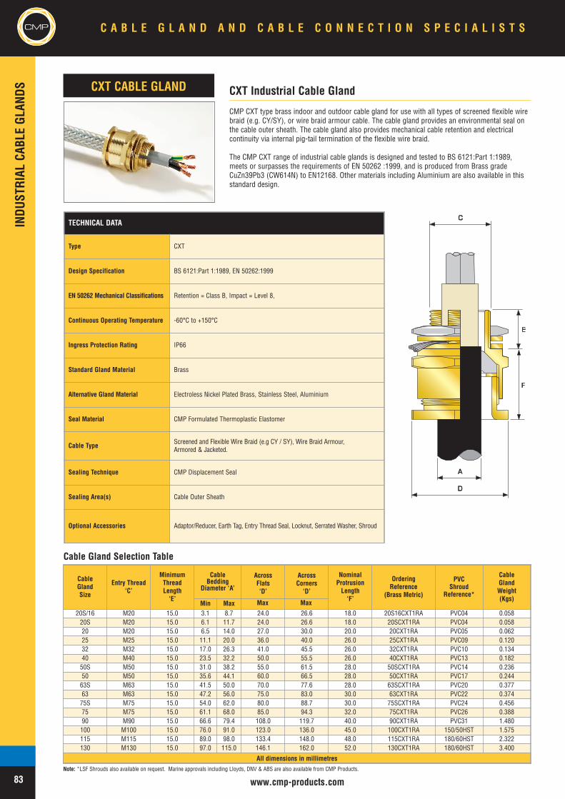
CMPINDU
STRIAL
CABL
EGL
ANDS
www.cmp-products.com
CMP CXT type brass indoor and outdoor cable gland for use with all types of screened flexible wirebraid (e.g. CY/SY), or wire braid armour cable. The cable gland provides an environmental seal onthe cable outer sheath. The cable gland also provides mechanical cable retention and electricalcontinuity via internal pig-tail termination of the flexible wire braid.
The CMP CXT range of industrial cable glands is designed and tested to BS 6121:Part 1:1989,meets or surpasses the requirements of EN 50262 :1999, and is produced from Brass gradeCuZn39Pb3 (CW614N) to EN12168. Other materials including Aluminium are also available in thisstandard design.
CXT Industrial Cable GlandCXT CABLE GLAND
CC
E
AA
DD
F
Cable Gland Selection Table
CableGlandSize
Entry Thread‘C’
MinimumThreadLength‘E’
CableBedding
Diameter ‘A’
AcrossFlats‘D’
AcrossCorners‘D’
NominalProtrusionLength‘F’
OrderingReference
(Brass Metric)
PVCShroud
Reference*
CableGlandWeight(Kgs)
Min Max20S/16 M20 15.0 3.1 8.7 24.0 26.6 18.0 20S16CXT1RA PVC04 0.05820S M20 15.0 6.1 11.7 24.0 26.6 18.0 20SCXT1RA PVC04 0.05820 M20 15.0 6.5 14.0 27.0 30.0 20.0 20CXT1RA PVC05 0.06225 M25 15.0 11.1 20.0 36.0 40.0 26.0 25CXT1RA PVC09 0.12032 M32 15.0 17.0 26.3 41.0 45.5 26.0 32CXT1RA PVC10 0.13440 M40 15.0 23.5 32.2 50.0 55.5 26.0 40CXT1RA PVC13 0.18250S M50 15.0 31.0 38.2 55.0 61.5 28.0 50SCXT1RA PVC14 0.23650 M50 15.0 35.6 44.1 60.0 66.5 28.0 50CXT1RA PVC17 0.24463S M63 15.0 41.5 50.0 70.0 77.6 28.0 63SCXT1RA PVC20 0.37763 M63 15.0 47.2 56.0 75.0 83.0 30.0 63CXT1RA PVC22 0.37475S M75 15.0 54.0 62.0 80.0 88.7 30.0 75SCXT1RA PVC24 0.45675 M75 15.0 61.1 68.0 85.0 94.3 32.0 75CXT1RA PVC26 0.38890 M90 15.0 66.6 79.4 108.0 119.7 40.0 90CXT1RA PVC31 1.480100 M100 15.0 76.0 91.0 123.0 136.0 45.0 100CXT1RA 150/50HST 1.575115 M115 15.0 89.0 98.0 133.4 148.0 48.0 115CXT1RA 180/60HST 2.322130 M130 15.0 97.0 115.0 146.1 162.0 52.0 130CXT1RA 180/60HST 3.400
All dimensions in millimetres
TECHNICAL DATA
Type CXT
Design Specification BS 6121:Part 1:1989, EN 50262:1999
EN 50262 Mechanical Classifications Retention = Class B, Impact = Level 8,
Continuous Operating Temperature -60°C to +150°C
Ingress Protection Rating IP66
Standard Gland Material Brass
Alternative Gland Material Electroless Nickel Plated Brass, Stainless Steel, Aluminium
Seal Material CMP Formulated Thermoplastic Elastomer
Cable Type Screened and Flexible Wire Braid (e.g CY / SY), Wire Braid Armour,Armored & Jacketed.
Sealing Technique CMP Displacement Seal
Sealing Area(s) Cable Outer Sheath
Optional Accessories Adaptor/Reducer, Earth Tag, Entry Thread Seal, Locknut, Serrated Washer, Shroud
C A B L E G L A N D A N D C A B L E C O N N E C T I O N S P E C I A L I S T S
83
CMP
Note: *LSF Shrouds also available on request. Marine approvals including Lloyds, DNV & ABS are also available from CMP Products.
Max Max
INDU
STRIAL
CABL
EGL
ANDS
www.cmp-products.com
CMP
CMP SS2KGP type brass indoor and outdoor cable gland for use with all types of Unarmouredcable, providing mechanical cable retention and an environmental seal on the cables inner and outersheath or a double seal on the cable outer sheath. Suitable for applications where superior cablepull out resistance is required.
The CMP SS2KGP range of industrial cable glands is designed and tested to BS 6121:Part 1:1989,meets or surpasses the requirements of EN 50262 :1999, and is produced from Brass gradeCuZn39Pb3 (CW614N) to EN12168.
SS2KGP Industrial Cable GlandSS2KGP CABLE GLAND
AA
CC
EE
BB
DD
FF
Cable Gland Selection Table
TECHNICAL DATA
Type SS2K/GP
Design Specification BS 6121:Part 1:1989, EN 50262:1999
EN 50262 Mechanical Classifications Retention = Class B, Impact = Level 8,
GOST R Certificate Number POCC GB. 05.H00110
GOST K Certificate Number KZ7500052.05.01.00063
RoK Permit for Use Number 08-067693
Continuous Operating Temperature -60°C to +150°C
Ingress Protection Rating IP66, IP67, IP68
Ingress Protection Document 5046 C549K
Deluge Protection Compliance DTS01 : 91
Deluge Protection Document 5046 C549K
Standard Gland Material Brass
Alternative Gland Material Electroless Nickel Plated Brass, Stainless Steel, Aluminium
Seal Material CMP Formulated Thermoplastic Elastomer
Cable Type Unarmoured
Sealing Technique CMP Displacement Seal
Sealing Area(s) Cable Inner Bedding and Cable Outer Sheath
Optional Accessories Adaptor/Reducer, Earth Tag, Entry Thread Seal, Locknut, Serrated Washer,Shroud
LLU
CableGlandSize
Available Entry Threads ‘C’ MinimumThreadLength‘E’
CableDiameter ‘A/B’
AcrossFlats‘D’
AcrossCorners‘D’
NominalProtrusionLength‘F’
OrderingReference
(Brass Metric)#
PVCShroud
Reference*
CableGlandWeight(Kgs)
Standard Option
Metric NPT NPT Min Max20S/16 M20 1/2” 3/4” 10.0 3.1 8.7 24.0 26.6 42.0 20S16SS2KGP1AA PVC04 0.07220S M20 1/2” 3/4” 10.0 6.1 11.7 24.0 26.6 42.0 20SSS2KGP1AA PVC04 0.07220 M20 1/2” 3/4” 10.0 6.5 14.0 27.0 31.0 47.0 20SSS2KGP1AA PVC05 0.07925 M25 3/4” 1” 10.0 11.1 20.0 36.0 39.0 56.0 25SS2KGP1AA PVC09 0.14932 M32 1” 1 1/4” 10.0 17.0 26.3 41.0 45.0 58.0 32SS2KGP1AA PVC10 0.17040 M40 1 1/4” 1 1/2” 15.0 23.5 32.2 50.0 53.5 60.0 40SS2KGP1AA PVC13 0.22450S M50 1 1/2” 2” 15.0 31.0 38.2 55.0 61.0 62.0 50SSS2KGP1AA PVC14 0.29850 M50 2” 2 1/2” 15.0 35.6 44.1 60.0 66.0 64.0 50SS2KGP1AA PVC17 0.30863S M63 2” 2 1/2” 15.0 41.5 50.0 70.0 77.5 66.0 63SSS2KGP1AA PVC20 0.48063 M63 2 1/2” 3” 15.0 47.2 56.0 75.0 84.0 67.0 63SS2KGP1AA PVC22 0.45875S M75 2 1/2” 3” 15.0 54.0 62.0 79.0 87.0 68.0 75SSS2KGP1AA PVC24 0.62175 M75 3” 3 1/2” 15.0 61.1 68.0 84.0 94.0 70.0 75SS2KGP1SA PVC26 0.52690 M90 3” 3 1/2” 15.0 66.6 79.4 108.0 120.0 75.0 90SS2KGP1AA PVC31 1.795100 M100 4” - 15.0 76.0 91.0 122.0 138.0 81.0 100SS2KGP1AA 150/50HST 2.100115 M115 - - 15.0 89.0 98.0 138.0 148.0 85.0 115SS2KGP1AA 180/60HST 3.096130 M130 - - 15.0 97.0 115.0 154.0 178.0 92.0 130SS2KGP1AA 180/60HST 4.530
All dimensions in millimetres
C A B L E G L A N D A N D C A B L E C O N N E C T I O N S P E C I A L I S T S CMP
84Note: *LSF Shrouds also available on request. Marine approvals including Lloyds, DNV & ABS are also available from CMP Products. # Other thread forms are available.
Max Max
CMPINDU
STRIAL
CABL
EGL
ANDS
www.cmp-products.com
CMP SS2KGP-PB type brass indoor and outdoor cable gland for use with all types of LeadSheathed Unarmoured, providing mechanical cable retention and environmental seal on the cableinner lead sheath and cable outer sheath. The cable gland also provides earth bonding of the innerlead covering or lead sheath.
The CMP SS2KGP-PB range of industrial cable glands is designed and tested to BS 6121:Part1:1989, meets or surpasses the requirements of EN 50262 :1999, and is produced from Brassgrade CuZn39Pb3 (CW614N) to EN12168.
SS2KGP-PB Industrial Cable GlandSS2KGP-PB CABLE GLAND
AA
CC
EE
BB
DD
FF
Cable Gland Selection Table
TECHNICAL DATA
Type SS2K GPPB
Design Specification BS 6121:Part 1:1989, EN 50262:1999
EN 50262 Mechanical Classifications Retention = Class B, Impact = Level 8,
EN 50262 Electrical Classifications Category A without use of an Earth Tag and Category B with an Earth Tag.
GOST R Certificate Number POCC GB. 05.H00110
GOST K Certificate Number KZ7500052.05.01.00063
RoK Permit for Use Number 08-067693
Continuous Operating Temperature -60° to +150°
Ingress Protection Rating IP66, IP67, IP68
Ingress Protection Document 5046 C549K
Deluge Protection Compliance DTS01 : 91
Deluge Protection Document 5046 C549K-D
Standard Gland Material Brass
Alternative Gland Material Electroless Nickel Plated Brass, Stainless Steel, Aluminium
Seal Material CMP Formulated Thermoplastic Elastomer
Cable Type Unarmoured Lead Sheathed
Sealing Technique CMP Displacement Seal
Sealing Area(s) Cable Inner Lead Sheath and Cable Outer Sheath
Optional Accessories Adaptor/Reducer, Earth Tag, Entry Thread Seal, Locknut, Serrated Washer,Shroud
CableGlandSize
Available Entry Threads ‘C’ MinimumThreadLength‘E’
LeadSheath/Overall
Diameter‘A/B’
AcrossFlats‘D’
AcrossCorners‘D’
NominalProtrusionLength‘F’
OrderingReference
(Brass Metric)#
PVCShroud
Reference*
CableGlandWeight(Kgs)
Standard Option
Metric NPT NPT Min Max20S/16 M20 1/2” 3/4” 10.0 3.1 8.7 24.0 26.6 42.0 20S16SS2KGPPB1RA PVC04 0.07220S M20 1/2” 3/4” 10.0 6.1 11.7 24.0 26.6 42.0 20SSS2KGPPB1RA PVC04 0.07220 M20 1/2” 3/4” 10.0 6.5 14.0 27.0 31.0 47.0 20SSS2KGPPB1RA PVC05 0.07925 M25 3/4” 1” 10.0 11.1 20.0 36.0 39.0 56.0 25SS2KGPPB1RA PVC09 0.14932 M32 1” 1 1/4” 10.0 17.0 26.3 41.0 45.0 58.0 32SS2KGPPB1RA PVC10 0.17040 M40 1 1/4” 1 1/2” 15.0 23.5 32.2 50.0 53.5 60.0 40SS2KGPPB1RA PVC13 0.22450S M50 1 1/2” 2” 15.0 31.0 38.2 55.0 61.0 62.0 50SSS2KGPPB1RA PVC14 0.29850 M50 2” 2 1/2” 15.0 35.6 44.1 60.0 66.0 64.0 50SS2KGPPB1RA PVC17 0.30863S M63 2” 2 1/2” 15.0 41.5 50.0 70.0 77.5 66.0 63SSS2KGPPB1RA PVC20 0.48063 M63 2 1/2” 3” 15.0 47.2 56.0 75.0 84.0 67.0 63SS2KGPPB1RA PVC22 0.45875S M75 2 1/2” 3” 15.0 54.0 62.0 79.0 87.0 68.0 75SSS2KGPPB1RA PVC24 0.62175 M75 3” 3 1/2” 15.0 61.1 68.0 84.0 94.0 70.0 75SS2KGPPB1RA PVC26 0.52690 M90 3” 3 1/2” 15.0 66.6 79.4 108.0 120.0 75.0 90SS2KGPPB1RA PVC31 1.795100 M100 4” - 15.0 76.0 91.0 122.0 138.0 81.0 100SS2KGPPB1RA 150/50HST 2.100115 M115 - - 15.0 89.0 98.0 138.0 148.0 85.0 115SS2KGPPB1RA 180/60HST 3.096130 M130 - - 15.0 97.0 115.0 154.0 178.0 92.0 130SS2KGPPB1RA 180/60HST 4.530
All dimensions in millimetres
C A B L E G L A N D A N D C A B L E C O N N E C T I O N S P E C I A L I S T S
85
CMP
Note: *LSF Shrouds also available on request. Marine approvals including Lloyds, DNV & ABS are also available from CMP Products. # Other thread forms are available.
LLU
Max Max
INDU
STRIAL
CABL
EGL
ANDS
www.cmp-products.com
CMP
CMP A2RC type brass indoor and outdoor conduit connection cable gland for use with all types ofUnarmoured cables housed in rigid or flexible conduit systems. The cable gland is equipped with arotating male or female connection which is available in a variety of thread forms for ease of conduitinstallation, including NPT and Metric. Customers are requested to kindly specify the male andfemale thread form and sizes required when ordering.
The CMP A2RC range of industrial cable glands is designed and tested to BS 6121:Part 1:1989,meets or surpasses the requirements of EN 50262 :1999, and is produced from Brass gradeCuZn39Pb3 (CW614N) to EN12168.
A2RC Industrial Cable Gland With Conduit Connection FacilityA2RC CABLE GLAND
AA
CC
EE
DD
FF
Cable Gland Selection Table
TECHNICAL DATA
Type A2RC
Design Specification BS 6121:Part 1:1989, EN 50262:1999
EN 50262 Mechanical Classifications Retention = Class B, Impact = Level 8,
EN 50262 Electrical Classifications Category A without use of an Earth Tag and Category B with an Earth Tag.
GOST R Certificate Number POCC GB. 05.H00110
GOST K Certificate Number KZ7500052.05.01.00063
RoK Permit for Use Number 08-067693
Continuous Operating Temperature -60°C to +150°C
Ingress Protection Rating IP66
Standard Gland Material Brass
Alternative Gland Material Electroless Nickel Plated Brass, Stainless Steel, Aluminium
Seal Material CMP Formulated Thermoplastic Elastomer
Cable Type Unarmoured
Sealing Technique CMP Displacement Seal
Sealing Area(s) Cable Outer Sheath
Optional Accessories Adaptor/Reducer, Earth Tag, Entry Thread Seal, Locknut, Serrated Washer,Shroud
LLU
CableGlandSize
Available Entry Threads ‘C’ StandardFemaleNPT
Thread
MinimumThreadLength‘E’
CableBeddingDiameter
‘A’
AcrossFlats‘D’
AcrossCorners‘D’
NominalProtrusionLength‘F’
OrderingReference
(Metric Mx NPT F)#
CableGlandWeight(Kgs)
Standard Option
Metric NPT NPT Min Max
20S/16 M20 1/2” 3/4” 1/2” 10.0 3.1 8.7 24.0 26.6 42.0 20S16A2RC1RA031 0.07520S M20 1/2” 3/4” 1/2” 10.0 6.1 11.7 24.0 26.6 42.0 20SA2RC1RA031 0.07520 M20 1/2” 3/4” 1/2” 10.0 6.5 14.0 27.0 30.0 47.0 20A2RC1RA031 0.08225 M25 3/4” 1” 3/4” 10.0 18.2 20.0 36.0 39.9 56.0 25A2RC1RA032 0.16532 M32 1” 1 1/4” 1” 10.0 23.7 26.3 41.0 45.5 58.0 32A2RC1RA033 0.18040 M40 1 1/4” 1 1/2” 1 1/4” 15.0 27.9 32.2 50.0 55.4 60.0 40A2RC1RA034 0.25050S M50 1 1/2” 2” 1 1/2” 15.0 35.2 38.2 55.0 61.0 62.0 50SA2RC1RA035 0.31050 M50 2” 2 1/2” 2” 15.0 40.4 44.1 60.0 66.5 64.0 50A2RC1RA036 0.33063S M63 2” 2 1/2” 2” 15.0 40.1 50.0 70.0 77.6 66.0 63SA2RC1RA036 0.48063 M63 2 1/2” 3” 2 1/2” 15.0 47.2 56.0 75.0 83.2 67.0 63A2RC1RA037 0.46075S M75 2 1/2” 3” 2 1/2” 15.0 59.0 62.0 80.0 88.7 68.0 75SA2RC1RA037 0.65075 M75 3” 3 1/2” 3” 15.0 66.7 68.0 85.0 94.2 70.0 75A2RC1RA038 0.58090 M90 3” 3 1/2” 3” 15.0 76.2 79.4 108.0 120.7 75.0 90A2RC1RA038 0.900
All dimensions in millimetres
C A B L E G L A N D A N D C A B L E C O N N E C T I O N S P E C I A L I S T S CMP
86Note: *LSF Shrouds also available on request. Marine approvals including Lloyds, DNV & ABS are also available from CMP Products. # Other thread forms are available.
Max Max
CMPINDU
STRIAL
CABL
EGL
ANDS
www.cmp-products.com
TECHNICAL DATA
Type E1U
Design Specification BS 6121: Part 1: 1989, EN 50262:1999
EN 50262 Mechanical Classifications Retention = Class B, Impact = Level 8,
EN 50262 Electrical Classifications Category A without use of an Earth Tag and Category B with an Earth Tag.
GOST R Certificate Number POCC GB. 05.H00110
GOST K Certificate Number KZ7500052.05.01.00063
RoK Permit for Use Number 08-067693
Lloyds Approval Number 01/00171
ABS Approval Number 01-LD 234401-PDA
Continuous Operating Temperature -60°C to +150°C
Ingress Protection Rating IP66 (IP67/IP68 also available)
Standard Gland Material Brass
Alternative Gland Material Electroless Nickel Plated Brass, Stainless Steel, Aluminium
Seal Material CMP Formulated Thermoplastic Elastomer
Cable TypeSingle Wire Armour (SWA), Aluminium Wire Armour (AWA), Pliable WireArmour (PWA), Steel Tape Armour (STA), Wire Braid Armour, Aluminium StripArmour (ASA), Screened Flexible Wire Braid (e.g. CY / SY), Armored & Jacketed
Armour Clamping Reversible Armour Cone & AnyWay Universal Clamping Ring
Sealing Technique CMP Inner Displacement Seal & Unique CMP "LRS" ™ Outer Seal(Load Retention Seal)
Sealing Area(s) Cable Inner Bedding & Cable Outer Sheath
Optional Accessories Adaptor/Reducer, Earth Tag, Entry Thread Seal, Locknut, Serrated Washer,Shroud
CMP E1U type brass indoor and outdoor cable gland for use with all types of armoured cablesproviding an environmental seal on the cable inner bedding and on the cable outer sheath. Thecable gland provides mechanical cable retention and electrical continuity via the armour termination.A reversible armour cone and AnyWay universal clamping ring arrangement allows the cable to beeasily disconnected from the equipment, for maintenance and change out etc. This feature alsofacilitates remote make off procedures when the termination is to be conducted in confined spacesor in areas of restricted access. Separate tightening actions for the inner displacement seal and thearmour termination affords maximum control over the pressure applied to the cable inner bedding.
The CMP E1U range of industrial cable glands is designed and tested to BS 6121:Part 1:1989,meets or surpasses the requirements of EN 50262 :1999, and is produced from Brass gradeCuZn39Pb3 (CW614N) to EN12168.
CableGlandSize
Available Entry Threads ‘C’MinimumThreadLength‘E’
CableBeddingDiameter
‘A’
Overall CableDiameter
‘B’
Armour Range †AcrossFlats‘D’
AcrossCorners‘D’
NominalProtrusionLength‘F’
OrderingReference
(Brass Metric)#
PVCShroud
Reference*
CableGlandWeight(Kgs)
Standard Option GroovedCone
SteppedCone
Metric NPT NPT Min Max Min Max Min Max Min Max
20S/16 M20 1/2” 3/4” 10.0 3.1 8.7 6.1 11.5 0 1.0 0.9 1.0 24.0 26.6 63.0 20S16E1U1RA PVC04 0.16320S M20 1/2” 3/4” 10.0 6.1 11.7 9.5 15.9 0 1.0 0.9 1.25 24.0 26.6 63.0 20SE1U1RA PVC04 0.16320 M20 1/2” 3/4” 10.0 6.5 14.0 12.5 20.9 0 1.0 0.9 1.25 30.5 33.3 67.0 20E1U1RA PVC06 0.21725S M25 3/4” 1” 10.0 11.1 20.0 14.0 22.0 0 1.0 1.25 1.6 37.5 40.5 78.0 25SE1U1RA PVC09 0.34525 M25 3/4” 1” 10.0 11.1 20.0 18.2 26.2 0 1.0 1.25 1.6 37.5 40.5 78.0 25E1U1RA PVC09 0.34532 M32 1” 1-1/4” 15.0 17.0 26.3 23.7 33.9 0 1.0 1.6 2.0 46.0 51.0 78.0 32E1U1RA PVC11 0.48440 M40 1-1/4” 1-1/2” 15.0 22.0 32.2 27.9 40.4 0 1.0 1.6 2.0 55.0 61.0 83.0 40E1U1RA PVC15 0.70050S M50 1-1/2” 2” 15.0 29.5 38.2 35.2 46.7 0 1.0 2.0 2.5 60.0 66.5 78.0 50SE1U1RA PVC18 0.80050 M50 2” 2-1/2” 15.0 35.6 44.1 40.4 53.1 0 1.0 2.0 2.5 70.0 78.6 81.0 50E1U1RA PVC21 0.83063S M63 2” 2-1/2” 15.0 40.1 50.0 45.6 59.4 0 1.0 2.0 2.5 75.0 83.2 93.0 63SE1U1RA PVC23 1.41563 M63 2-1/2” 3” 15.0 47.2 56.0 54.6 65.9 0 1.0 2.0 2.5 80.0 89.0 95.0 63E1U1RA PVC25 1.51475S M75 2-1/2” 3” 15.0 52.8 62.0 59.0 72.1 0 1.0 2.0 2.5 89.0 101.6 103.0 75SE1U1RA PVC28 2.19975 M75 3” 3-1/2” 15.0 59.1 68.0 66.7 78.5 0 1.0 2.0 2.5 99.0 111.1 110.0 75E1U1RA PVC30 2.77090 M90 3 3-1/2” 15.0 66.6 79.4 76.2 90.4 0 1.6 3.15 3.15 114.0 128.6 136.0 90E1U1RA PVC32 4.478100 M100 4” - 15.0 76.0 91.0 89.1 101.5 0 1.6 3.15 4.0 123.0 138.0 145.0 100E1U1RA 150/50HST 4.700115 M115 - - 15.0 86.0 98.0 101.3 110.3 0 1.6 3.15 4.0 133.4 147.6 160.0 115E1U1RA 180/60HST 5.300130 M130 - - 15.0 97.0 115.0 114.0 123.3 0 1.6 3.15 4.0 146.1 161.9 185.0 130E1U1RA 180/60HST 5.900
All dimensions in millimetres
E1U Universal Industrial Cable GlandE1U CABLE GLAND
AA
BB
DD
CC
EE
FF
Cable Gland Selection Table
LLU
C A B L E G L A N D A N D C A B L E C O N N E C T I O N S P E C I A L I S T S
87
CMP
Note: *LSF Shrouds also available on request. † Alternative armour clamping range available for non-standard armour sizes. Marine approvals including Lloyds, DNV & ABS are also available from CMP Products.# Other thread forms are available.
Deluge ProofOption
Note:Deluge proof version available
Max Max
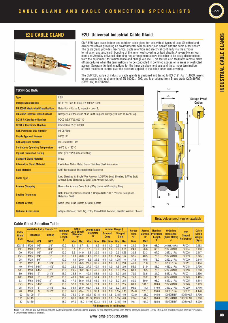
INDU
STRIAL
CABL
EGL
ANDS
www.cmp-products.com
CMP
CableGlandSize
Available Entry Threads ‘C’MinimumThreadLength‘E’
CableLead SheathDiameter
‘A’
Overall CableDiameter
‘B’
Armour Range † AcrossFlats‘D’
AcrossCorners‘D’
NominalProtrusionLength‘F’
OrderingReference
(Brass Metric)#
PVCShroud
Reference*
CableGlandWeight(Kgs)
Standard Option GroovedCone
SteppedCone
Metric NPT NPT Min Max Min Max Min Max Min Max
20S/16 M20 1/2” 3/4” 10.0 3.1 8.7 6.1 11.5 0.0 1.0 0.9 1.0 24.0 26.6 63.0 20S16E2U1RA PVC04 0.16320S M20 1/2” 3/4” 10.0 6.1 11.7 9.5 15.9 0.0 1.0 0.9 1.25 24.0 26.6 63.0 20SE2U1RA PVC04 0.16320 M20 1/2” 3/4” 10.0 6.5 14.0 12.5 20.9 0.0 1.0 0.9 1.25 30.5 33.3 67.0 20E2U1RA PVC06 0.21725S M25 3/4” 1” 10.0 11.1 20.0 14.0 22.0 0.0 1.0 1.25 1.6 37.5 40.5 78.0 25SE2U1RA PVC09 0.34525 M25 3/4” 1” 10.0 11.1 20.0 18.2 26.2 0.0 1.0 1.25 1.6 37.5 40.5 78.0 25E2U1RA PVC09 0.34532 M32 1” 1-1/4” 15.0 17.0 26.3 23.7 33.9 0.0 1.0 1.6 2.0 46.0 51.0 78.0 32E2U1RA PVC11 0.48440 M40 1-1/4” 1-1/2” 15.0 22.0 32.2 27.9 40.4 0.0 1.0 1.6 2.0 55.0 61.0 83.0 40E2U1RA PVC15 0.70050S M50 1-1/2” 2” 15.0 29.5 38.2 35.2 46.7 0.0 1.0 2.0 2.5 60.0 66.5 78.0 50SE2U1RA PVC18 0.80050 M50 2” 2-1/2” 15.0 35.6 44.1 40.4 53.1 0.0 1.0 2.0 2.5 70.0 78.6 81.0 50E2U1RA PVC21 0.83063S M63 2” 2-1/2” 15.0 40.1 50.0 45.6 59.4 0.0 1.0 2.0 2.5 75.0 83.2 93.0 63SE2U1RA PVC23 1.41563 M63 2-1/2” 3” 15.0 47.2 56.0 54.6 65.9 0.0 1.0 2.0 2.5 80.0 89.0 95.0 63E2U1RA PVC25 1.51475S M75 2-1/2” 3” 15.0 52.8 62.0 59.0 72.1 0.0 1.0 2.0 2.5 89.0 101.6 103.0 75SE2U1RA PVC28 2.19975 M75 3” 3-1/2” 15.0 59.1 68.0 66.7 78.5 0.0 1.0 2.0 2.5 99.0 111.1 110.0 75E2U1RA PVC30 2.77090 M90 3 3-1/2” 15.0 66.6 79.4 76.2 90.4 0.0 1.6 3.15 3.15 114.0 128.6 136.0 90E2U1RA PVC32 4.478100 M100 4” - 15.0 76.0 91.0 89.1 101.5 0.0 1.6 3.15 4.0 123.0 138.0 145.0 100E2U1RA 150/50HST 4.700115 M115 - - 15.0 86.0 98.0 101.3 110.3 0.0 1.6 3.15 4.0 133.4 147.6 160.0 115E2U1RA 180/60HST 5.300130 M130 - - 15.0 97.0 115.0 114.0 123.3 0.0 1.6 3.15 4.0 146.1 161.9 185.0 130E2U1RA 180/60HST 5.900
All dimensions in millimetres
TECHNICAL DATA
Type E2U
Design Specification BS 6121: Part 1: 1989, EN 50262:1999
EN 50262 Mechanical Classifications Retention = Class B, Impact = Level 8,
EN 50262 Electrical Classifications Category A without use of an Earth Tag and Category B with an Earth Tag.
GOST R Certificate Number POCC GB. 05.H00110
GOST K Certificate Number KZ7500052.05.01.00063
RoK Permit for Use Number 08-067693
Lloyds Approval Number 01/00171
ABS Approval Number 01-LD 234401-PDA
Continuous Operating Temperature -60°C to +150°C
Ingress Protection Rating IP66 (IP67/IP68 also available)
Standard Gland Material Brass
Alternative Gland Material Electroless Nickel Plated Brass, Stainless Steel, Aluminium
Seal Material CMP Formulated Thermoplastic Elastomer
Cable Type Lead Sheathed & Single Wire Armour (LC/SWA), Lead Sheathed & Wire BraidArmour, Lead Sheathed & Steel Tape Armour (LC/STA)
Armour Clamping Reversible Armour Cone & AnyWay Universal Clamping Ring
Sealing Technique CMP Inner Displacement Seal & Unique CMP "LRS" ™ Outer Seal (LoadRetention Seal)
Sealing Area(s) Cable Inner Lead Sheath & Outer Sheath
Optional Accessories Adaptor/Reducer, Earth Tag, Entry Thread Seal, Locknut, Serrated Washer, Shroud
LLU
CMP E2U type brass indoor and outdoor cable gland for use with all types of Lead Sheathed andArmoured cables providing an environmental seal on inner lead sheath and the cable outer sheath.The cable gland provides mechanical cable retention and electrical continuity via the armourtermination and also earth bonding of the inner lead covering or lead sheath. A reversible armourcone and AnyWay universal clamping ring arrangement allows the cable to be easily disconnectedfrom the equipment, for maintenance and change out etc. This feature also facilitates remote makeoff procedures when the termination is to be conducted in confined spaces or in areas of restrictedaccess. Separate tightening actions for the inner displacement seal and the armour terminationaffords maximum control over the pressure applied to the cable inner lead covering.
The CMP E2U range of industrial cable glands is designed and tested to BS 6121:Part 1:1989, meetsor surpasses the requirements of EN 50262 :1999, and is produced from Brass grade CuZn39Pb3(CW614N) to EN12168.
E2U Universal Industrial Cable GlandE2U CABLE GLAND
AA
BB
DD
CC
EE
FF
Cable Gland Selection Table
Note: *LSF Shrouds also available on request. † Alternative armour clamping range available for non-standard armour sizes. Marine approvals including Lloyds, DNV & ABS are also available from CMP Products.# Other thread forms are available.
C A B L E G L A N D A N D C A B L E C O N N E C T I O N S P E C I A L I S T S CMP
88
Note:Deluge proof version available
Deluge ProofOption
Max Max
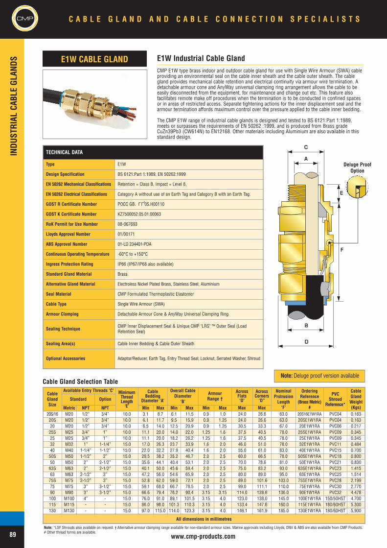
CMPINDU
STRIAL
CABL
EGL
ANDS
www.cmp-products.com
CMP E1W type brass indoor and outdoor cable gland for use with Single Wire Armour (SWA) cableproviding an environmental seal on the cable inner sheath and the cable outer sheath. The cablegland provides mechanical cable retention and electrical continuity via armour wire termination. Adetachable armour cone and AnyWay universal clamping ring arrangement allows the cable to beeasily disconnected from the equipment, for maintenance and change out etc. This feature alsofacilitates remote make off procedures when the termination is to be conducted in confined spacesor in areas of restricted access. Separate tightening actions for the inner displacement seal and thearmour termination affords maximum control over the pressure applied to the cable inner bedding.
The CMP E1W range of industrial cable glands is designed and tested to BS 6121:Part 1:1989,meets or surpasses the requirements of EN 50262 :1999, and is produced from Brass gradeCuZn39Pb3 (CW614N) to EN12168. Other materials including Aluminium are also available in thisstandard design.
CableGlandSize
Available Entry Threads ‘C’ MinimumThreadLength‘E’
CableBedding
Diameter ‘A’
Overall CableDiameter
‘B’
ArmourRange †
NominalProtrusionLength‘F’
OrderingReference
(BrassMetric)#
PVCShroud
Reference*
CableGlandWeight(Kgs)
Standard Option
Metric NPT NPT Min Max Min Max Min Max20S/16 M20 1/2” 3/4” 10.0 3.1 8.7 6.1 11.5 0.9 1.0 24.0 26.6 63.0 20S16E1W1RA PVC04 0.16320S M20 1/2” 3/4” 10.0 6.1 11.7 9.5 15.9 0.9 1.25 24.0 26.6 63.0 20SE1W1RA PVC04 0.16320 M20 1/2” 3/4” 10.0 6.5 14.0 12.5 20.9 0.9 1.25 30.5 33.3 67.0 20E1W1RA PVC06 0.21725S M25 3/4” 1” 10.0 11.1 20.0 14.0 22.0 1.25 1.6 37.5 40.5 78.0 25SE1W1RA PVC09 0.34525 M25 3/4” 1” 10.0 11.1 20.0 18.2 26.2 1.25 1.6 37.5 40.5 78.0 25E1W1RA PVC09 0.34532 M32 1” 1-1/4” 15.0 17.0 26.3 23.7 33.9 1.6 2.0 46.0 51.0 78.0 32E1W1RA PVC11 0.48440 M40 1-1/4” 1-1/2” 15.0 22.0 32.2 27.9 40.4 1.6 2.0 55.0 61.0 83.0 40E1W1RA PVC15 0.70050S M50 1-1/2” 2” 15.0 29.5 38.2 35.2 46.7 2.0 2.5 60.0 66.5 78.0 50SE1W1RA PVC18 0.80050 M50 2” 2-1/2” 15.0 35.6 44.1 40.4 53.1 2.0 2.5 70.0 78.6 81.0 50E1W1RA PVC21 0.83063S M63 2” 2-1/2” 15.0 40.1 50.0 45.6 59.4 2.0 2.5 75.0 83.2 93.0 63SE1W1RA PVC23 1.41563 M63 2-1/2” 3” 15.0 47.2 56.0 54.6 65.9 2.0 2.5 80.0 89.0 95.0 63E1W1RA PVC25 1.51475S M75 2-1/2” 3” 15.0 52.8 62.0 59.0 72.1 2.0 2.5 89.0 101.6 103.0 75SE1W1RA PVC28 2.19975 M75 3” 3-1/2” 15.0 59.1 68.0 66.7 78.5 2.0 2.5 99.0 111.1 110.0 75E1W1RA PVC30 2.77090 M90 3” 3-1/2” 15.0 66.6 79.4 76.2 90.4 3.15 3.15 114.0 128.6 136.0 90E1W1RA PVC32 4.478100 M100 4” - 15.0 76.0 91.0 89.1 101.5 3.15 4.0 123.0 138.0 145.0 100E1W1RA 150/50HST 4.700115 M115 - - 15.0 86.0 98.0 101.3 110.3 3.15 4.0 133.4 147.6 160.0 115E1W1RA 180/60HST 5.300130 M130 - - 15.0 97.0 115.0 114.0 123.3 3.15 4.0 146.1 161.9 185.0 130E1W1RA 180/60HST 5.900
All dimensions in millimetres
E1W Industrial Cable GlandE1W CABLE GLAND
Cable Gland Selection Table
TECHNICAL DATA
Type E1W
Design Specification BS 6121:Part 1:1989, EN 50262:1999
EN 50262 Mechanical Classifications Retention = Class B, Impact = Level 8,
EN 50262 Electrical Classifications Category A without use of an Earth Tag and Category B with an Earth Tag.
GOST R Certificate Number POCC GB. 05.H00110
GOST K Certificate Number KZ7500052.05.01.00063
RoK Permit for Use Number 08-067693
Lloyds Approval Number 01/00171
ABS Approval Number 01-LD 234401-PDA
Continuous Operating Temperature -60°C to +150°C
Ingress Protection Rating IP66 (IP67/IP68 also available)
Standard Gland Material Brass
Alternative Gland Material Electroless Nickel Plated Brass, Stainless Steel, Aluminium
Seal Material CMP Formulated Thermoplastic Elastomer
Cable Type Single Wire Armour (SWA)
Armour Clamping Detachable Armour Cone & AnyWay Universal Clamping Ring
Sealing Technique CMP Inner Displacement Seal & Unique CMP "LRS" ™ Outer Seal (LoadRetention Seal)
Sealing Area(s) Cable Inner Bedding & Cable Outer Sheath
Optional Accessories Adaptor/Reducer, Earth Tag, Entry Thread Seal, Locknut, Serrated Washer, Shroud
LLU
C A B L E G L A N D A N D C A B L E C O N N E C T I O N S P E C I A L I S T S
89
CMP
AA
BB
DD
CC
EE
FF
Deluge ProofOption
Note: *LSF Shrouds also available on request. † Alternative armour clamping range available for non-standard armour sizes. Marine approvals including Lloyds, DNV & ABS are also available from CMP Products.# Other thread forms are available.
AcrossFlats‘D’
AcrossCorners‘D”
Note:Deluge proof version available
Max Max

INDU
STRIAL
CABL
EGL
ANDS
www.cmp-products.com
CMP
CableGlandSize
Available Entry Threads ‘C’ MinimumThreadLength‘E’
CableLead SheathDiameter ‘A’
Overall CableDiameter
‘B’
ArmourRange †
NominalProtrusionLength ‘F’
OrderingReference
(BrassMetric)#
PVCShroud
Reference*
CableGlandWeight(Kgs)
Standard Option
Metric NPT NPT Min Max Min Max Min Max
20S/16 M20 1/2” 3/4” 10.0 3.1 8.7 6.1 11.5 0.9 1.0 24.0 26.6 63.0 20S16E2W1RA PVC04 0.16320S M20 1/2” 3/4” 10.0 6.1 11.7 9.5 15.9 0.9 1.25 24.0 26.6 63.0 20SE2W1RA PVC04 0.16320 M20 1/2” 3/4” 10.0 6.5 14.0 12.5 20.9 0.9 1.25 30.5 33.3 67.0 20E2W1RA PVC06 0.21725S M25 3/4” 1” 10.0 11.1 20.0 14.0 22.0 1.25 1.6 37.5 40.5 78.0 25SE2W1RA PVC09 0.34525 M25 3/4” 1” 10.0 11.1 20.0 18.2 26.2 1.25 1.6 37.5 40.5 78.0 25E2W1RA PVC09 0.34532 M32 1” 1-1/4” 15.0 17.0 26.3 23.7 33.9 1.6 2.0 46.0 51.0 78.0 32E2W1RA PVC11 0.48440 M40 1-1/4” 1-1/2” 15.0 22.0 32.2 27.9 40.4 1.6 2.0 55.0 61.0 83.0 40E2W1RA PVC15 0.70050S M50 1-1/2” 2” 15.0 29.5 38.2 35.2 46.7 2.0 2.5 60.0 66.5 78.0 50SE2W1RA PVC18 0.80050 M50 2” 2-1/2” 15.0 35.6 44.1 40.4 53.1 2.0 2.5 70.0 78.6 81.0 50E2W1RA PVC21 0.83063S M63 2” 2-1/2” 15.0 40.1 50.0 45.6 59.4 2.0 2.5 75.0 83.2 93.0 63SE2W1RA PVC23 1.41563 M63 2-1/2” 3” 15.0 47.2 56.0 54.6 65.9 2.0 2.5 80.0 89.0 95.0 63E2W1RA PVC25 1.51475S M75 2-1/2” 3” 15.0 52.8 62.0 59.0 72.1 2.0 2.5 89.0 101.6 103.0 75SE2W1RA PVC28 2.19975 M75 3” 3-1/2” 15.0 59.1 68.0 66.7 78.5 2.0 2.5 99.0 111.1 110.0 75E2W1RA PVC30 2.77090 M90 3” 3-1/2” 15.0 66.6 79.4 76.2 90.4 3.15 3.15 114.0 128.6 136.0 90E2W1RA PVC32 4.478100 M100 4” - 15.0 76.0 91.0 89.1 101.5 3.15 4.0 123.0 138.0 145.0 100E2W1RA 150/50HST 4.700115 M115 - - 15.0 86.0 98.0 101.3 110.3 3.15 4.0 133.4 147.6 160.0 115E2W1RA 180/60HST 5.300130 M130 - - 15.0 97.0 115.0 114.0 123.3 3.15 4.0 146.1 161.9 185.0 130E2W1RA 180/60HST 5.900
All dimensions in millimetres
CMP E2W type brass indoor and outdoor cable gland for use with all types of Lead Sheathed andSingle Wire Armour (SWA) cable providing an environmental seal on the cable inner lead sheath andcable outer sheath. The cable gland provides mechanical cable retention and electrical continuity via thearmour termination and also earth bonding of the inner lead covering or lead sheath. A detachablearmour cone and AnyWay universal clamping ring arrangement allows the cable to be easilydisconnected from the equipment, for maintenance and change out etc. This feature also facilitatesremote make off procedures when the termination is to be conducted in confined spaces or in areas ofrestricted access. Separate tightening actions for the inner displacement seal and the armourtermination affords maximum control over the pressure applied to the cable inner lead covering.
The CMP E2W range of industrial cable glands is designed and tested to BS 6121:Part 1:1989, meets orsurpasses the requirements of EN 50262 :1999, and is produced from Brass grade CuZn39Pb3(CW614N) to EN12168. Other materials including Aluminium are also available in this standard design.
E2W Industrial Cable GlandE2W CABLE GLAND
BB
DD
AA
CC
EE
FF
Cable Gland Selection Table
TECHNICAL DATA
Type E2W
Design Specification BS 6121:Part 1:1989, EN 50262:1999
EN 50262 Mechanical Classifications Retention = Class B, Impact = Level 8,
EN 50262 Electrical Classifications Category A without use of an Earth Tag and Category B with an Earth Tag.
GOST R Certificate Number POCC GB. 05.H00110
GOST K Certificate Number KZ7500052.05.01.00063
RoK Permit for Use Number 08-067693
Lloyds Approval Number 01/00171
ABS Approval Number 01-LD 234401-PDA
Continuous Operating Temperature -60°C to +150°C
Ingress Protection Rating IP66 (IP67/IP68 also available)
Standard Gland Material Brass
Alternative Gland Material Aluminium, Electroless Nickel Plated Brass, Stainless Steel
Seal Material CMP Formulated Thermoplastic Elastomer
Cable Type Lead Sheathed & Single Wire Armour (LC/SWA)
Armour Clamping Detachable Armour Cone & AnyWay Universal Clamping Ring
Sealing Technique CMP Inner Displacement Seal & Unique CMP "LRS" ™ Outer Seal (LoadRetention Seal)
Sealing Area(s) Inner & Outer Sheath
Optional Accessories Adaptor/Reducer, Earth Tag, Entry Thread Seal, Locknut, Serrated Washer, Shroud
LLU
C A B L E G L A N D A N D C A B L E C O N N E C T I O N S P E C I A L I S T S CMP
90
Deluge ProofOption
Note: *LSF Shrouds also available on request. † Alternative armour clamping range available for non-standard armour sizes. Marine approvals including Lloyds, DNV & ABS are also available from CMP Products.# Other thread forms are available.
AcrossFlats‘D’
AcrossCorners‘D’
Note:Deluge proof version available
Max Max
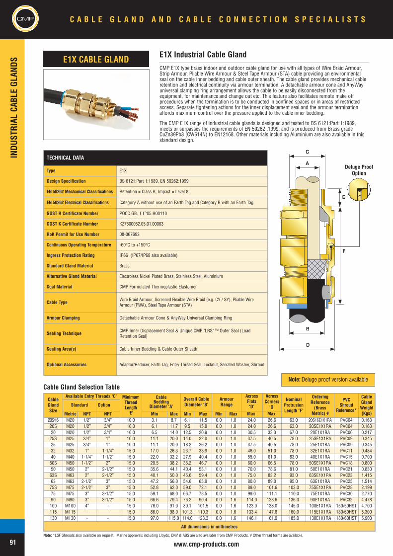
CMPINDU
STRIAL
CABL
EGL
ANDS
www.cmp-products.com
CMP E1X type brass indoor and outdoor cable gland for use with all types of Wire Braid Armour,Strip Armour, Pliable Wire Armour & Steel Tape Armour (STA) cable providing an environmentalseal on the cable inner bedding and cable outer sheath. The cable gland provides mechanical cableretention and electrical continuity via armour termination. A detachable armour cone and AnyWayuniversal clamping ring arrangement allows the cable to be easily disconnected from theequipment, for maintenance and change out etc. This feature also facilitates remote make offprocedures when the termination is to be conducted in confined spaces or in areas of restrictedaccess. Separate tightening actions for the inner displacement seal and the armour terminationaffords maximum control over the pressure applied to the cable inner bedding.
The CMP E1X range of industrial cable glands is designed and tested to BS 6121:Part 1:1989,meets or surpasses the requirements of EN 50262 :1999, and is produced from Brass gradeCuZn39Pb3 (CW614N) to EN12168. Other materials including Aluminium are also available in thisstandard design.
E1X Industrial Cable GlandE1X CABLE GLAND
AA
BB
DD
CC
EE
FF
Cable Gland Selection Table
CableGlandSize
Available Entry Threads ‘C’ MinimumThreadLength‘E’
CableBedding
Diameter ‘A’
Overall CableDiameter ‘B’
ArmourRange
AcrossFlats‘D’
AcrossCorners‘D’
NominalProtrusionLength ‘F’
OrderingReference(Brass
Metric) #
PVCShroud
Reference*
CableGlandWeight(Kgs)
Standard Option
Metric NPT NPT Min Max Min Max Min Max20S/16 M20 1/2” 3/4” 10.0 3.1 8.7 6.1 11.5 0.0 1.0 24.0 26.6 63.0 20S16E1X1RA PVC04 0.16320S M20 1/2” 3/4” 10.0 6.1 11.7 9.5 15.9 0.0 1.0 24.0 26.6 63.0 20SE1X1RA PVC04 0.16320 M20 1/2” 3/4” 10.0 6.5 14.0 12.5 20.9 0.0 1.0 30.5 33.3 67.0 20E1X1RA PVC06 0.21725S M25 3/4” 1” 10.0 11.1 20.0 14.0 22.0 0.0 1.0 37.5 40.5 78.0 25SE1X1RA PVC09 0.34525 M25 3/4” 1” 10.0 11.1 20.0 18.2 26.2 0.0 1.0 37.5 40.5 78.0 25E1X1RA PVC09 0.34532 M32 1” 1-1/4” 15.0 17.0 26.3 23.7 33.9 0.0 1.0 46.0 51.0 78.0 32E1X1RA PVC11 0.48440 M40 1-1/4” 1-1/2” 15.0 22.0 32.2 27.9 40.4 0.0 1.0 55.0 61.0 83.0 40E1X1RA PVC15 0.70050S M50 1-1/2” 2” 15.0 29.5 38.2 35.2 46.7 0.0 1.0 60.0 66.5 78.0 50SE1X1RA PVC18 0.80050 M50 2” 2-1/2” 15.0 35.6 44.1 40.4 53.1 0.0 1.0 70.0 78.6 81.0 50E1X1RA PVC21 0.83063S M63 2” 2-1/2” 15.0 40.1 50.0 45.6 59.4 0.0 1.0 75.0 83.2 93.0 63SE1X1RA PVC23 1.41563 M63 2-1/2” 3” 15.0 47.2 56.0 54.6 65.9 0.0 1.0 80.0 89.0 95.0 63E1X1RA PVC25 1.51475S M75 2-1/2” 3” 15.0 52.8 62.0 59.0 72.1 0.0 1.0 89.0 101.6 103.0 75SE1X1RA PVC28 2.19975 M75 3” 3-1/2” 15.0 59.1 68.0 66.7 78.5 0.0 1.0 99.0 111.1 110.0 75E1X1RA PVC30 2.77090 M90 3” 3-1/2” 15.0 66.6 79.4 76.2 90.4 0.0 1.6 114.0 128.6 136.0 90E1X1RA PVC32 4.478100 M100 4” - 15.0 76.0 91.0 89.1 101.5 0.0 1.6 123.0 138.0 145.0 100E1X1RA 150/50HST 4.700115 M115 - - 15.0 86.0 98.0 101.3 110.3 0.0 1.6 133.4 147.6 160.0 115E1X1RA 180/60HST 5.300130 M130 - - 15.0 97.0 115.0 114.0 123.3 0.0 1.6 146.1 161.9 185.0 130E1X1RA 180/60HST 5.900
All dimensions in millimetres
TECHNICAL DATA
Type E1X
Design Specification BS 6121:Part 1:1989, EN 50262:1999
EN 50262 Mechanical Classifications Retention = Class B, Impact = Level 8,
EN 50262 Electrical Classifications Category A without use of an Earth Tag and Category B with an Earth Tag.
GOST R Certificate Number POCC GB. 05.H00110
GOST K Certificate Number KZ7500052.05.01.00063
RoK Permit for Use Number 08-067693
Continuous Operating Temperature -60°C to +150°C
Ingress Protection Rating IP66 (IP67/IP68 also available)
Standard Gland Material Brass
Alternative Gland Material Electroless Nickel Plated Brass, Stainless Steel, Aluminium
Seal Material CMP Formulated Thermoplastic Elastomer
Cable Type Wire Braid Armour, Screened Flexible Wire Braid (e.g. CY / SY), Pliable WireArmour (PWA), Steel Tape Armour (STA)
Armour Clamping Detachable Armour Cone & AnyWay Universal Clamping Ring
Sealing Technique CMP Inner Displacement Seal & Unique CMP "LRS" ™ Outer Seal (LoadRetention Seal)
Sealing Area(s) Cable Inner Bedding & Cable Outer Sheath
Optional Accessories Adaptor/Reducer, Earth Tag, Entry Thread Seal, Locknut, Serrated Washer, Shroud
LLU
C A B L E G L A N D A N D C A B L E C O N N E C T I O N S P E C I A L I S T S
91
CMP
Deluge ProofOption
Note: *LSF Shrouds also available on request. Marine approvals including Lloyds, DNV & ABS are also available from CMP Products. # Other thread forms are available.
Note:Deluge proof version available
Max Max
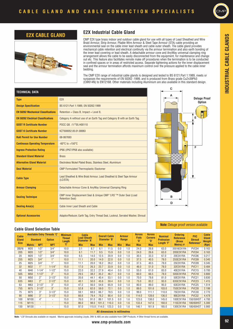
INDU
STRIAL
CABL
EGL
ANDS
www.cmp-products.com
CMP
CMP E2X type brass indoor and outdoor cable gland for use with all types of Lead Sheathed and WireBraid Armour, Strip Armour, Pliable Wire Armour & Steel Tape Armour (STA) cable providing anenvironmental seal on the cable inner lead sheath and cable outer sheath. The cable gland providesmechanical cable retention and electrical continuity via the armour termination and also earth bonding ofthe inner lead covering or lead sheath. A detachable armour cone and AnyWay universal clamping ringarrangement allows the cable to be easily disconnected from the equipment, for maintenance and changeout etc. This feature also facilitates remote make off procedures when the termination is to be conductedin confined spaces or in areas of restricted access. Separate tightening actions for the inner displacementseal and the armour termination affords maximum control over the pressure applied to the cable innerbedding.
The CMP E2X range of industrial cable glands is designed and tested to BS 6121:Part 1:1989, meets orsurpasses the requirements of EN 50262 :1999, and is produced from Brass grade CuZn39Pb3(CW614N) to EN12168. Other materials including Aluminium are also available in this standard design.
E2X Industrial Cable GlandE2X CABLE GLAND
BB
DD
AA
CC
EE
FF
Cable Gland Selection Table
CableGlandSize
Available Entry Threads ‘C’ MinimumThreadLength‘E’
CableLead SheathDiameter ‘A’
Overall CableDiameter ‘B’
ArmourRange
AcrossFlats‘D’
AcrossCorners‘D’
NominalProtrusionLength ‘F’
OrderingReference(Brass
Metric) #
PVCShroud
Reference*
CableGlandWeight(Kgs)
Standard Option
Metric NPT NPT Min Max Min Max Min Max20S/16 M20 1/2” 3/4” 10.0 3.1 8.7 6.1 11.5 0.0 1.0 24.0 26.6 63.0 20S16E2X1RA PVC04 0.16320S M20 1/2” 3/4” 10.0 6.1 11.7 9.5 15.9 0.0 1.0 24.0 26.6 63.0 20SE2X1RA PVC04 0.16320 M20 1/2” 3/4” 10.0 6.5 14.0 12.5 20.9 0.0 1.0 30.5 33.3 67.0 20E2X1RA PVC06 0.21725S M25 3/4” 1” 10.0 11.1 20.0 14.0 22.0 0.0 1.0 37.5 40.5 78.0 25SE2X1RA PVC09 0.34525 M25 3/4” 1” 10.0 11.1 20.0 18.2 26.2 0.0 1.0 37.5 40.5 78.0 25E2X1RA PVC09 0.34532 M32 1” 1-1/4” 15.0 17.0 26.3 23.7 33.9 0.0 1.0 46.0 51.0 78.0 32E2X1RA PVC11 0.48440 M40 1-1/4” 1-1/2” 15.0 22.0 32.2 27.9 40.4 0.0 1.0 55.0 61.0 83.0 40E2X1RA PVC15 0.70050S M50 1-1/2” 2” 15.0 29.5 38.2 35.2 46.7 0.0 1.0 60.0 66.5 78.0 50SE2X1RA PVC18 0.80050 M50 2” 2-1/2” 15.0 35.6 44.1 40.4 53.1 0.0 1.0 70.0 78.6 81.0 50E2X1RA PVC21 0.83063S M63 2” 2-1/2” 15.0 40.1 50.0 45.6 59.4 0.0 1.0 75.0 83.2 93.0 63SE2X1RA PVC23 1.41563 M63 2-1/2” 3” 15.0 47.2 56.0 54.6 65.9 0.0 1.0 80.0 89.0 95.0 63E2X1RA PVC25 1.51475S M75 2-1/2” 3” 15.0 52.8 62.0 59.0 72.1 0.0 1.0 89.0 101.6 103.0 75SE2X1RA PVC28 2.19975 M75 3” 3-1/2” 15.0 59.1 68.0 66.7 78.5 0.0 1.0 99.0 111.1 110.0 75E2X1RA PVC30 2.77090 M90 3” 3-1/2” 15.0 66.6 79.4 76.2 90.4 0.0 1.6 114.0 128.6 136.0 90E2X1RA PVC32 4.478100 M100 4” - 15.0 76.0 91.0 89.1 101.5 0.0 1.6 123.0 138.0 145.0 100E2X1RA 150/50HST 4.700115 M115 - - 15.0 86.0 98.0 101.3 110.3 0.0 1.6 133.4 147.6 160.0 115E2X1RA 180/60HST 5.300130 M130 - - 15.0 97.0 115.0 114.0 123.3 0.0 1.6 146.1 161.9 185.0 130E2X1RA 180/60HST 5.900
All dimensions in millimetres
TECHNICAL DATA
Type E2X
Design Specification BS 6121:Part 1:1989, EN 50262:1999
EN 50262 Mechanical Classifications Retention = Class B, Impact = Level 8,
EN 50262 Electrical Classifications Category A without use of an Earth Tag and Category B with an Earth Tag.
GOST R Certificate Number POCC GB. 05.H00110
GOST K Certificate Number KZ7500052.05.01.00063
RoK Permit for Use Number 08-067693
Continuous Operating Temperature -60°C to +150°C
Ingress Protection Rating IP66 (IP67/IP68 also available)
Standard Gland Material Brass
Alternative Gland Material Electroless Nickel Plated Brass, Stainless Steel, Aluminium
Seal Material CMP Formulated Thermoplastic Elastomer
Cable Type Lead Sheathed & Wire Braid Armour, Lead Sheathed & Steel Tape Armour(LC/STA)
Armour Clamping Detachable Armour Cone & AnyWay Universal Clamping Ring
Sealing Technique CMP Inner Displacement Seal & Unique CMP "LRS" ™ Outer Seal (LoadRetention Seal)
Sealing Area(s) Cable Inner Lead Sheath and Cable
Optional Accessories Adaptor/Reducer, Earth Tag, Entry Thread Seal, Locknut, Serrated Washer, Shroud
LLU
C A B L E G L A N D A N D C A B L E C O N N E C T I O N S P E C I A L I S T S CMP
92
Deluge ProofOption
Note: *LSF Shrouds also available on request. Marine approvals including Lloyds, DNV & ABS are also available from CMP Products. # Other thread forms are available.
Note:Deluge proof version available
Max Max
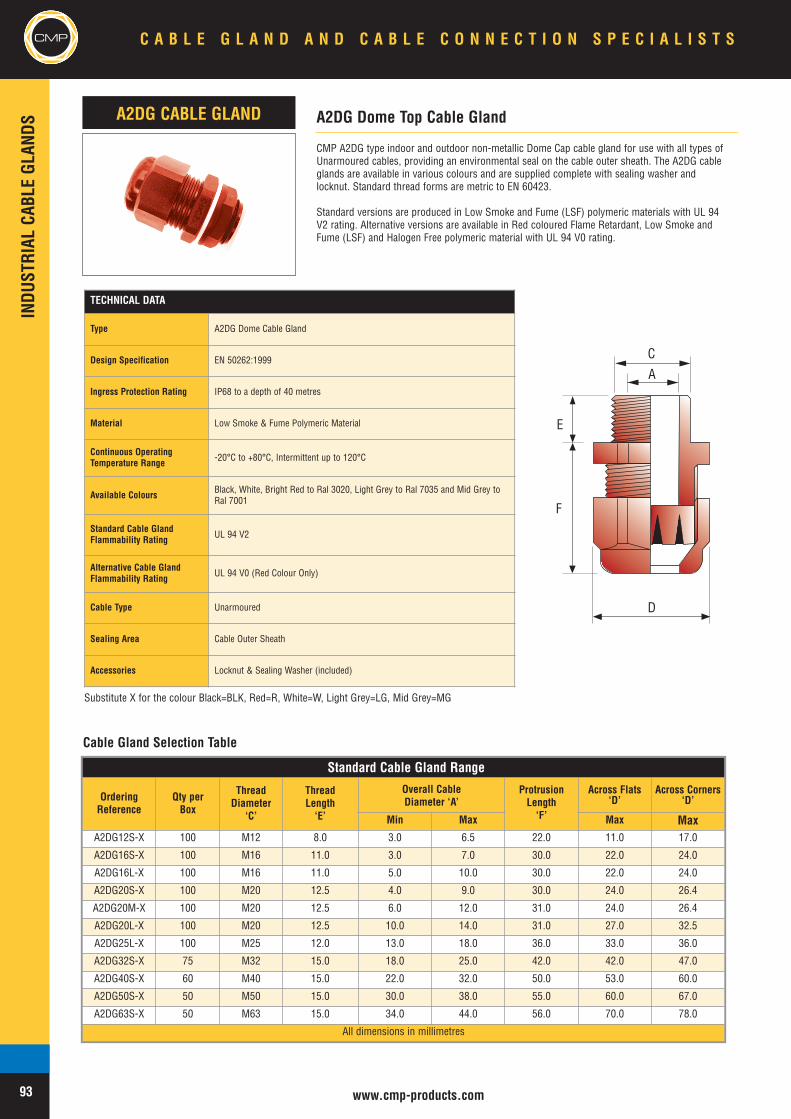
CMP A2DG type indoor and outdoor non-metallic Dome Cap cable gland for use with all types ofUnarmoured cables, providing an environmental seal on the cable outer sheath. The A2DG cableglands are available in various colours and are supplied complete with sealing washer andlocknut. Standard thread forms are metric to EN 60423.
Standard versions are produced in Low Smoke and Fume (LSF) polymeric materials with UL 94V2 rating. Alternative versions are available in Red coloured Flame Retardant, Low Smoke andFume (LSF) and Halogen Free polymeric material with UL 94 V0 rating.
A2DG Dome Top Cable GlandA2DG CABLE GLAND
CMP
www.cmp-products.com
INDU
STRIAL
CABL
EGL
ANDS
CMP C A B L E G L A N D A N D C A B L E C O N N E C T I O N S P E C I A L I S T S
93
Standard Cable Gland Range
OrderingReference
Qty perBox
ThreadDiameter
‘C’
ThreadLength‘E’
Overall CableDiameter ‘A’
ProtrusionLength‘F’
Across Flats‘D’
Across Corners‘D’
Min Max Max MaxA2DG12S-X 100 M12 8.0 3.0 6.5 22.0 11.0 17.0
A2DG16S-X 100 M16 11.0 3.0 7.0 30.0 22.0 24.0
A2DG16L-X 100 M16 11.0 5.0 10.0 30.0 22.0 24.0
A2DG20S-X 100 M20 12.5 4.0 9.0 30.0 24.0 26.4
A2DG20M-X 100 M20 12.5 6.0 12.0 31.0 24.0 26.4
A2DG20L-X 100 M20 12.5 10.0 14.0 31.0 27.0 32.5
A2DG25L-X 100 M25 12.0 13.0 18.0 36.0 33.0 36.0
A2DG32S-X 75 M32 15.0 18.0 25.0 42.0 42.0 47.0
A2DG40S-X 60 M40 15.0 22.0 32.0 50.0 53.0 60.0
A2DG50S-X 50 M50 15.0 30.0 38.0 55.0 60.0 67.0
A2DG63S-X 50 M63 15.0 34.0 44.0 56.0 70.0 78.0
All dimensions in millimetres
Cable Gland Selection Table
Substitute X for the colour Black=BLK, Red=R, White=W, Light Grey=LG, Mid Grey=MG
TECHNICAL DATA
Type A2DG Dome Cable Gland
Design Specification EN 50262:1999
Ingress Protection Rating IP68 to a depth of 40 metres
Material Low Smoke & Fume Polymeric Material
Continuous OperatingTemperature Range -20°C to +80°C, Intermittent up to 120°C
Available Colours Black, White, Bright Red to Ral 3020, Light Grey to Ral 7035 and Mid Grey toRal 7001
Standard Cable GlandFlammability Rating UL 94 V2
Alternative Cable GlandFlammability Rating UL 94 V0 (Red Colour Only)
Cable Type Unarmoured
Sealing Area Cable Outer Sheath
Accessories Locknut & Sealing Washer (included)
E
F
C
D
A
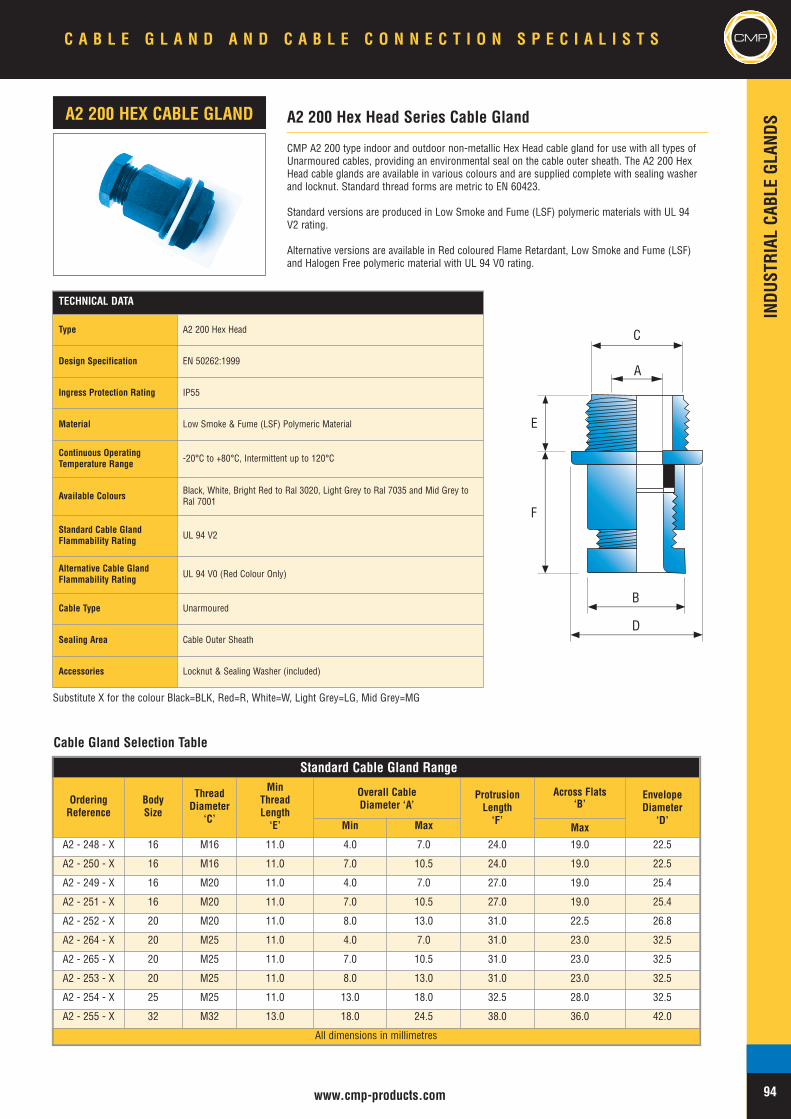
CMPC A B L E G L A N D A N D C A B L E C O N N E C T I O N S P E C I A L I S T S CMP
www.cmp-products.com
INDU
STRIAL
CABL
EGL
ANDS
94
Standard Cable Gland Range
OrderingReference
BodySize
ThreadDiameter
‘C’
MinThreadLength‘E’
Overall CableDiameter ‘A’
ProtrusionLength‘F’
Across Flats‘B’
EnvelopeDiameter
‘D’Min Max Max
A2 - 248 - X 16 M16 11.0 4.0 7.0 24.0 19.0 22.5
A2 - 250 - X 16 M16 11.0 7.0 10.5 24.0 19.0 22.5
A2 - 249 - X 16 M20 11.0 4.0 7.0 27.0 19.0 25.4
A2 - 251 - X 16 M20 11.0 7.0 10.5 27.0 19.0 25.4
A2 - 252 - X 20 M20 11.0 8.0 13.0 31.0 22.5 26.8
A2 - 264 - X 20 M25 11.0 4.0 7.0 31.0 23.0 32.5
A2 - 265 - X 20 M25 11.0 7.0 10.5 31.0 23.0 32.5
A2 - 253 - X 20 M25 11.0 8.0 13.0 31.0 23.0 32.5
A2 - 254 - X 25 M25 11.0 13.0 18.0 32.5 28.0 32.5
A2 - 255 - X 32 M32 13.0 18.0 24.5 38.0 36.0 42.0
All dimensions in millimetres
CMP A2 200 type indoor and outdoor non-metallic Hex Head cable gland for use with all types ofUnarmoured cables, providing an environmental seal on the cable outer sheath. The A2 200 HexHead cable glands are available in various colours and are supplied complete with sealing washerand locknut. Standard thread forms are metric to EN 60423.
Standard versions are produced in Low Smoke and Fume (LSF) polymeric materials with UL 94V2 rating.
Alternative versions are available in Red coloured Flame Retardant, Low Smoke and Fume (LSF)and Halogen Free polymeric material with UL 94 V0 rating.
A2 200 Hex Head Series Cable GlandA2 200 HEX CABLE GLAND
Cable Gland Selection Table
Substitute X for the colour Black=BLK, Red=R, White=W, Light Grey=LG, Mid Grey=MG
E
F
C
B
D
A
TECHNICAL DATA
Type A2 200 Hex Head
Design Specification EN 50262:1999
Ingress Protection Rating IP55
Material Low Smoke & Fume (LSF) Polymeric Material
Continuous OperatingTemperature Range -20°C to +80°C, Intermittent up to 120°C
Available Colours Black, White, Bright Red to Ral 3020, Light Grey to Ral 7035 and Mid Grey toRal 7001
Standard Cable GlandFlammability Rating UL 94 V2
Alternative Cable GlandFlammability Rating UL 94 V0 (Red Colour Only)
Cable Type Unarmoured
Sealing Area Cable Outer Sheath
Accessories Locknut & Sealing Washer (included)
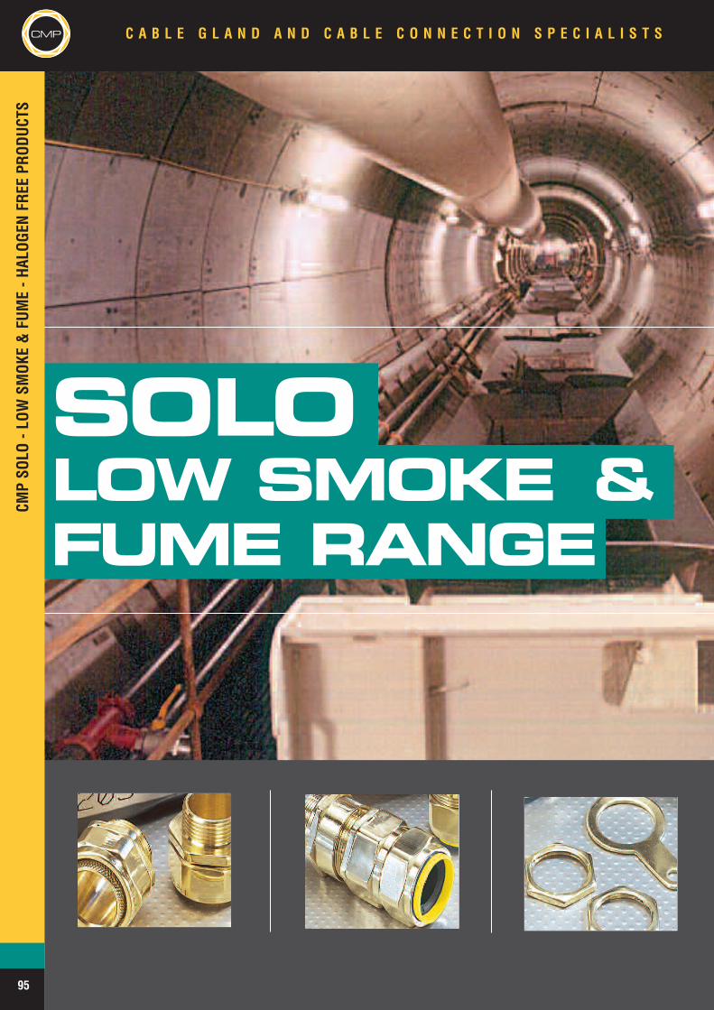
SOLOLOW SMOKE &FUME RANGE
CMPSO
LO-L
OWSM
OKE&FU
ME-H
ALOG
ENFR
EEPR
ODUC
TSC A B L E G L A N D A N D C A B L E C O N N E C T I O N S P E C I A L I S T SCMP
95
CMPSO
LO-L
OWSM
OKE&FU
ME-H
ALOG
ENFR
EEPR
ODUC
TS
C A B L E G L A N D A N D C A B L E C O N N E C T I O N S P E C I A L I S T S
APPLICATION
The outstanding safety benefits of low smokeand fume (LSF) or halogen free cables materialshave already led to their increased use in areasconsidered to be potentially at risk in situations offire hazard. Typical examples are in tunnels,deep bore underground metro systems, andpublic buildings where the risk of smokeinhalation, in the event of fire, is at it’s greatest.The CMP SOLO LSF range of cable glands andaccessories meets the most stringentrequirements and provide a single, simplesolution for specifiers and users in meeting LSFand Halogen Free requirements.
PRODUCTS
The CMP SOLO LSF option can be provided forall types of cable glands shown in this catalogue.
SPECIFICATIONS & APPROVALS
Designed and tested for compliance with EN50267-2-1, the Test on Gases Evolved DuringCombustion of Materials applied to cables underfire conditions.Meets the requirements of London UndergroundLtd Fire Safety Regulations.
TO ORDER GLAND KITS
Add LSF2RA after the gland size and type e.g.25CWLSF2RA to denote that a Gland Kit isrequired.
CMP
96
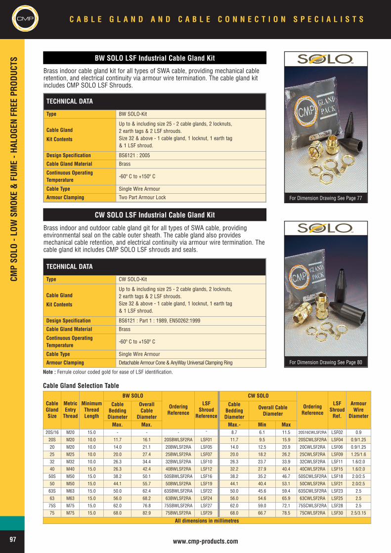
CMPCM
PSO
LO-L
OWSM
OKE&FU
ME-H
ALOG
ENFR
EEPR
ODUC
TS
www.cmp-products.com
BW SOLO LSF Industrial Cable Gland Kit
CW SOLO LSF Industrial Cable Gland Kit
For Dimension Drawing See Page 77
For Dimension Drawing See Page 80
Cable Gland Selection Table
TECHNICAL DATA
Type BW SOLO-Kit
Cable Gland
Kit Contents
Up to & including size 25 - 2 cable glands, 2 locknuts,2 earth tags & 2 LSF shrouds.Size 32 & above - 1 cable gland, 1 locknut, 1 earth tag& 1 LSF shroud.
Design Specification BS6121 : 2005
Cable Gland Material Brass
Continuous OperatingTemperature
-60º C to +150º C
Cable Type Single Wire Armour
Armour Clamping Two Part Armour Lock
TECHNICAL DATA
Type CW SOLO-Kit
Cable Gland
Kit Contents
Up to & including size 25 - 2 cable glands, 2 locknuts,2 earth tags & 2 LSF shrouds.Size 32 & above - 1 cable gland, 1 locknut, 1 earth tag& 1 LSF shroud.
Design Specification BS6121 : Part 1 : 1989, EN50262:1999
Cable Gland Material Brass
Continuous OperatingTemperature
-60º C to +150º C
Cable Type Single Wire Armour
Armour Clamping Detachable Armour Cone & AnyWay Universal Clamping Ring
Brass indoor cable gland kit for all types of SWA cable, providing mechanical cableretention, and electrical continuity via armour wire termination. The cable gland kitincludes CMP SOLO LSF Shrouds.
Brass indoor and outdoor cable gland git for all types of SWA cable, providingenvironmental seal on the cable outer sheath. The cable gland also providesmechanical cable retention, and electrical continuity via armour wire termination. Thecable gland kit includes CMP SOLO LSF shrouds and seals.
CableGlandSize
MetricEntryThread
MinimumThreadLength
BW SOLO
OrderingReference
LSFShroud
Reference
CW SOLO
OrderingReference
LSFShroudRef.
ArmourWire
Diameter
CableBeddingDiameter
OverallCable
Diameter
CableBeddingDiameter
Overall CableDiameter
Max. Max. Max.- Min Max20S/16 M20 15.0 - - - - 8.7 6.1 11.5 20S16CWLSF2RA LSF02 0.9
20S M20 10.0 11.7 16.1 20SBWLSF2RA LSF01 11.7 9.5 15.9 20SCWLSF2RA LSF04 0.9/1.25
20 M20 10.0 14.0 21.1 20BWLSF2RA LSF05 14.0 12.5 20.9 20CWLSF2RA LSF06 0.9/1.25
25 M25 10.0 20.0 27.4 25BWLSF2RA LSF07 20.0 18.2 26.2 25CWLSF2RA LSF09 1.25/1.6
32 M32 10.0 26.3 34.4 32BWLSF2RA LSF10 26.3 23.7 33.9 32CWLSF2RA LSF11 1.6/2.0
40 M40 15.0 26.3 42.4 40BWLSF2RA LSF12 32.2 27.9 40.4 40CWLSF2RA LSF15 1.6/2.0
50S M50 15.0 38.2 50.1 50SBWLSF2RA LSF16 38.2 35.2 46.7 50SCWLSF2RA LSF18 2.0/2.5
50 M50 15.0 44.1 55.7 50BWLSF2RA LSF19 44.1 40.4 53.1 50CWLSF2RA LSF21 2.0/2.5
63S M63 15.0 50.0 62.4 63SBWLSF2RA LSF22 50.0 45.6 59.4 63SCWLSF2RA LSF23 2.5
63 M63 15.0 56.0 68.2 63BWLSF2RA LSF24 56.0 54.6 65.9 63CWLSF2RA LSF25 2.5
75S M75 15.0 62.0 76.8 75SBWLSF2RA LSF27 62.0 59.0 72.1 75SCWLSF2RA LSF28 2.5
75 M75 15.0 68.0 82.9 75BWLSF2RA LSF29 68.0 66.7 78.5 75CWLSF2RA LSF30 2.5/3.15
All dimensions in millimetres
Note : Ferrule colour coded gold for ease of LSF identification.
TM
TMTM
C A B L E G L A N D A N D C A B L E C O N N E C T I O N S P E C I A L I S T SCMP
97
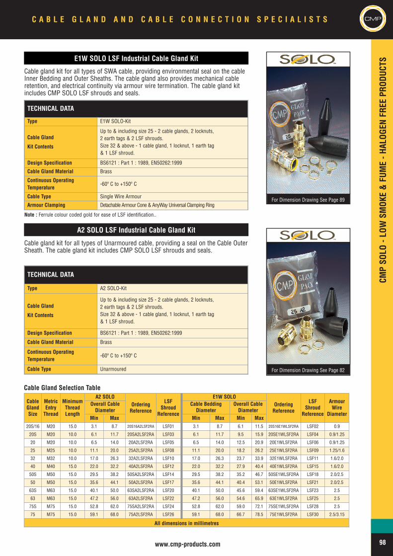
CMPSO
LO-L
OWSM
OKE&FU
ME-H
ALOG
ENFR
EEPR
ODUC
TS
www.cmp-products.com
CMP
E1W SOLO LSF Industrial Cable Gland Kit
A2 SOLO LSF Industrial Cable Gland Kit
For Dimension Drawing See Page 89
For Dimension Drawing See Page 82
TM
Cable Gland Selection Table
TECHNICAL DATA
Type E1W SOLO-Kit
Cable Gland
Kit Contents
Up to & including size 25 - 2 cable glands, 2 locknuts,2 earth tags & 2 LSF shrouds.Size 32 & above - 1 cable gland, 1 locknut, 1 earth tag& 1 LSF shroud.
Design Specification BS6121 : Part 1 : 1989, EN50262:1999
Cable Gland Material Brass
Continuous OperatingTemperature
-60º C to +150º C
Cable Type Single Wire Armour
Armour Clamping Detachable Armour Cone & AnyWay Universal Clamping Ring
TECHNICAL DATA
Type A2 SOLO-Kit
Cable Gland
Kit Contents
Up to & including size 25 - 2 cable glands, 2 locknuts,2 earth tags & 2 LSF shrouds.Size 32 & above - 1 cable gland, 1 locknut, 1 earth tag& 1 LSF shroud.
Design Specification BS6121 : Part 1 : 1989, EN50262:1999
Cable Gland Material Brass
Continuous OperatingTemperature
-60º C to +150º C
Cable Type Unarmoured
Cable gland kit for all types of SWA cable, providing environmental seal on the cableInner Bedding and Outer Sheaths. The cable gland also provides mechanical cableretention, and electrical continuity via armour wire termination. The cable gland kitincludes CMP SOLO LSF shrouds and seals.
Cable gland kit for all types of Unarmoured cable, providing a seal on the Cable OuterSheath. The cable gland kit includes CMP SOLO LSF shrouds and seals.
CableGlandSize
MetricEntryThread
MinimumThreadLength
A2 SOLOOrderingReference
LSFShroud
Reference
E1W SOLOOrderingReference
LSFShroud
Reference
ArmourWire
Diameter
Overall CableDiameter
Cable BeddingDiameter
Overall CableDiameter
Min Max Min Max Min Max20S/16 M20 15.0 3.1 8.7 20S16A2LSF2RA LSF01 3.1 8.7 6.1 11.5 20S16E1WLSF2RA LSF02 0.9
20S M20 10.0 6.1 11.7 20SA2LSF2RA LSF03 6.1 11.7 9.5 15.9 20SE1WLSF2RA LSF04 0.9/1.25
20 M20 10.0 6.5 14.0 20A2LSF2RA LSF05 6.5 14.0 12.5 20.9 20E1WLSF2RA LSF06 0.9/1.25
25 M25 10.0 11.1 20.0 25A2LSF2RA LSF08 11.1 20.0 18.2 26.2 25E1WLSF2RA LSF09 1.25/1.6
32 M32 10.0 17.0 26.3 32A2LSF2RA LSF10 17.0 26.3 23.7 33.9 32E1WLSF2RA LSF11 1.6/2.0
40 M40 15.0 22.0 32.2 40A2LSF2RA LSF12 22.0 32.2 27.9 40.4 40E1WLSF2RA LSF15 1.6/2.0
50S M50 15.0 29.5 38.2 50SA2LSF2RA LSF14 29.5 38.2 35.2 46.7 50SE1WLSF2RA LSF18 2.0/2.5
50 M50 15.0 35.6 44.1 50A2LSF2RA LSF17 35.6 44.1 40.4 53.1 50E1WLSF2RA LSF21 2.0/2.5
63S M63 15.0 40.1 50.0 63SA2LSF2RA LSF20 40.1 50.0 45.6 59.4 63SE1WLSF2RA LSF23 2.5
63 M63 15.0 47.2 56.0 63A2LSF2RA LSF22 47.2 56.0 54.6 65.9 63E1WLSF2RA LSF25 2.5
75S M75 15.0 52.8 62.0 75SA2LSF2RA LSF24 52.8 62.0 59.0 72.1 75SE1WLSF2RA LSF28 2.5
75 M75 15.0 59.1 68.0 75A2LSF2RA LSF26 59.1 68.0 66.7 78.5 75E1WLSF2RA LSF30 2.5/3.15
All dimensions in millimetres
Note : Ferrule colour coded gold for ease of LSF identification..
TMTM
C A B L E G L A N D A N D C A B L E C O N N E C T I O N S P E C I A L I S T S CMP
98
CMPCM
PCIEL
-CAS
TINTEGR
ALEA
RTHLU
GEQ
UIPP
EDPR
ODUC
TSC A B L E G L A N D A N D C A B L E C O N N E C T I O N S P E C I A L I S T S
CIELCAST INTEGRALEARTH LUG
99
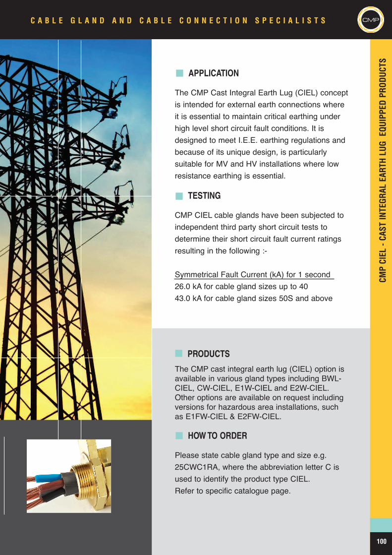
CMPCIEL
-CAS
TINTEGR
ALEA
RTHLU
GEQ
UIPP
EDPR
ODUC
TS
C A B L E G L A N D A N D C A B L E C O N N E C T I O N S P E C I A L I S T S CMP
APPLICATION
The CMP Cast Integral Earth Lug (CIEL) conceptis intended for external earth connections whereit is essential to maintain critical earthing underhigh level short circuit fault conditions. It isdesigned to meet I.E.E. earthing regulations andbecause of its unique design, is particularlysuitable for MV and HV installations where lowresistance earthing is essential.
TESTING
CMP CIEL cable glands have been subjected toindependent third party short circuit tests todetermine their short circuit fault current ratingsresulting in the following :-
Symmetrical Fault Current (kA) for 1 second26.0 kA for cable gland sizes up to 4043.0 kA for cable gland sizes 50S and above
PRODUCTS
The CMP cast integral earth lug (CIEL) option isavailable in various gland types including BWL-CIEL, CW-CIEL, E1W-CIEL and E2W-CIEL.Other options are available on request includingversions for hazardous area installations, suchas E1FW-CIEL & E2FW-CIEL.
HOW TO ORDER
Please state cable gland type and size e.g.25CWC1RA, where the abbreviation letter C isused to identify the product type CIEL.Refer to specific catalogue page.
100
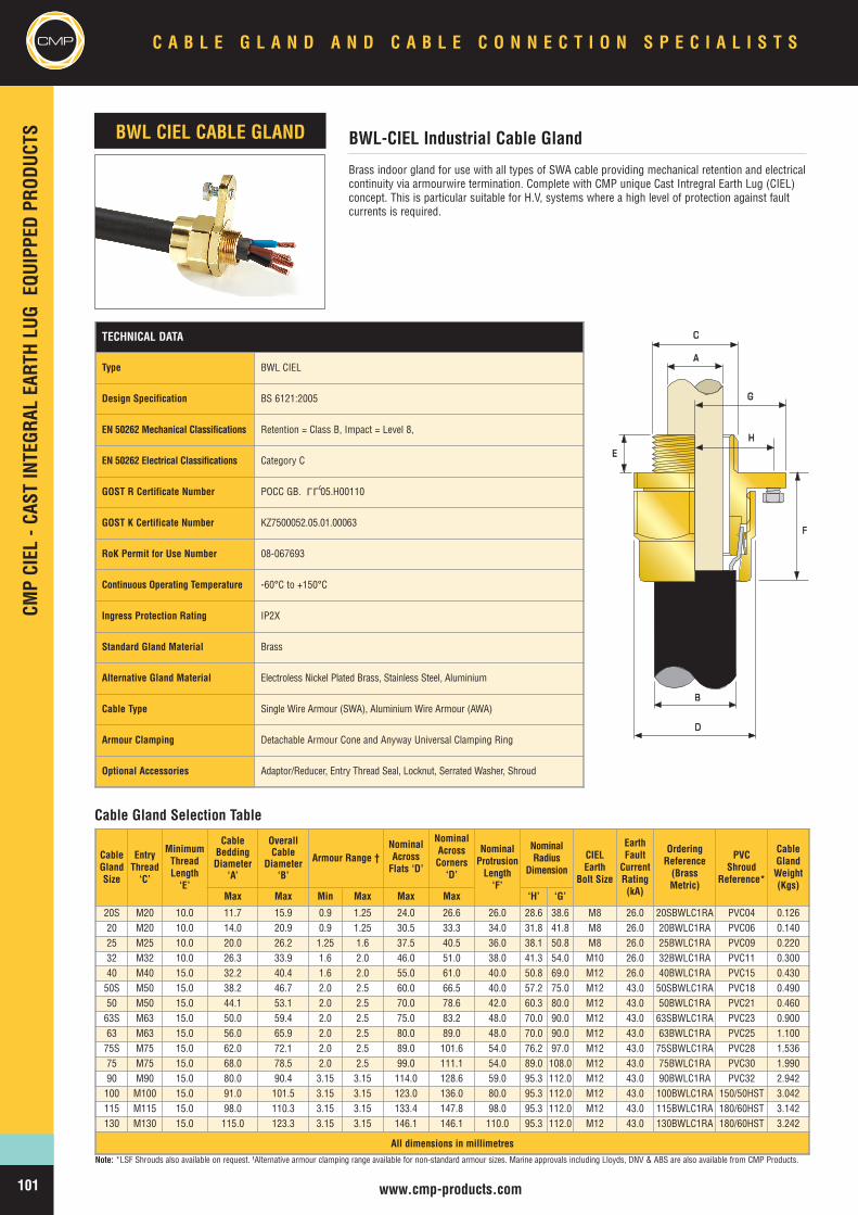
CMPCM
PCIEL
-CAS
TINTEGR
ALEA
RTHLU
GEQ
UIPP
EDPR
ODUC
TS
www.cmp-products.com
Brass indoor gland for use with all types of SWA cable providing mechanical retention and electricalcontinuity via armourwire termination. Complete with CMP unique Cast Intregral Earth Lug (CIEL)concept. This is particular suitable for H.V, systems where a high level of protection against faultcurrents is required.
BWL-CIEL Industrial Cable GlandBWL CIEL CABLE GLAND
BB
DD
AA
CC
HH
GG
EE
FF
Cable Gland Selection Table
Note: *LSF Shrouds also available on request. †Alternative armour clamping range available for non-standard armour sizes. Marine approvals including Lloyds, DNV & ABS are also available from CMP Products.
TECHNICAL DATA
Type BWL CIEL
Design Specification BS 6121:2005
EN 50262 Mechanical Classifications Retention = Class B, Impact = Level 8,
EN 50262 Electrical Classifications Category C
GOST R Certificate Number POCC GB. 05.H00110
GOST K Certificate Number KZ7500052.05.01.00063
RoK Permit for Use Number 08-067693
Continuous Operating Temperature -60°C to +150°C
Ingress Protection Rating IP2X
Standard Gland Material Brass
Alternative Gland Material Electroless Nickel Plated Brass, Stainless Steel, Aluminium
Cable Type Single Wire Armour (SWA), Aluminium Wire Armour (AWA)
Armour Clamping Detachable Armour Cone and Anyway Universal Clamping Ring
Optional Accessories Adaptor/Reducer, Entry Thread Seal, Locknut, Serrated Washer, Shroud
LLU
CableGlandSize
EntryThread‘C’
MinimumThreadLength‘E’
CableBeddingDiameter
‘A’
OverallCable
Diameter‘B’
Armour Range †NominalAcrossFlats ‘D’
NominalAcrossCorners‘D’
NominalProtrusionLength‘F’
NominalRadius
DimensionCIELEarth
Bolt Size
EarthFaultCurrentRating(kA)
OrderingReference(BrassMetric)
PVCShroud
Reference*
CableGlandWeight(Kgs)
Max Max Min Max Max Max ‘H’ ‘G’
20S M20 10.0 11.7 15.9 0.9 1.25 24.0 26.6 26.0 28.6 38.6 M8 26.0 20SBWLC1RA PVC04 0.12620 M20 10.0 14.0 20.9 0.9 1.25 30.5 33.3 34.0 31.8 41.8 M8 26.0 20BWLC1RA PVC06 0.14025 M25 10.0 20.0 26.2 1.25 1.6 37.5 40.5 36.0 38.1 50.8 M8 26.0 25BWLC1RA PVC09 0.22032 M32 10.0 26.3 33.9 1.6 2.0 46.0 51.0 38.0 41.3 54.0 M10 26.0 32BWLC1RA PVC11 0.30040 M40 15.0 32.2 40.4 1.6 2.0 55.0 61.0 40.0 50.8 69.0 M12 26.0 40BWLC1RA PVC15 0.43050S M50 15.0 38.2 46.7 2.0 2.5 60.0 66.5 40.0 57.2 75.0 M12 43.0 50SBWLC1RA PVC18 0.49050 M50 15.0 44.1 53.1 2.0 2.5 70.0 78.6 42.0 60.3 80.0 M12 43.0 50BWLC1RA PVC21 0.46063S M63 15.0 50.0 59.4 2.0 2.5 75.0 83.2 48.0 70.0 90.0 M12 43.0 63SBWLC1RA PVC23 0.90063 M63 15.0 56.0 65.9 2.0 2.5 80.0 89.0 48.0 70.0 90.0 M12 43.0 63BWLC1RA PVC25 1.10075S M75 15.0 62.0 72.1 2.0 2.5 89.0 101.6 54.0 76.2 97.0 M12 43.0 75SBWLC1RA PVC28 1.53675 M75 15.0 68.0 78.5 2.0 2.5 99.0 111.1 54.0 89.0 108.0 M12 43.0 75BWLC1RA PVC30 1.99090 M90 15.0 80.0 90.4 3.15 3.15 114.0 128.6 59.0 95.3 112.0 M12 43.0 90BWLC1RA PVC32 2.942100 M100 15.0 91.0 101.5 3.15 3.15 123.0 136.0 80.0 95.3 112.0 M12 43.0 100BWLC1RA 150/50HST 3.042115 M115 15.0 98.0 110.3 3.15 3.15 133.4 147.8 98.0 95.3 112.0 M12 43.0 115BWLC1RA 180/60HST 3.142130 M130 15.0 115.0 123.3 3.15 3.15 146.1 146.1 110.0 95.3 112.0 M12 43.0 130BWLC1RA 180/60HST 3.242
All dimensions in millimetres
C A B L E G L A N D A N D C A B L E C O N N E C T I O N S P E C I A L I S T SCMP
101
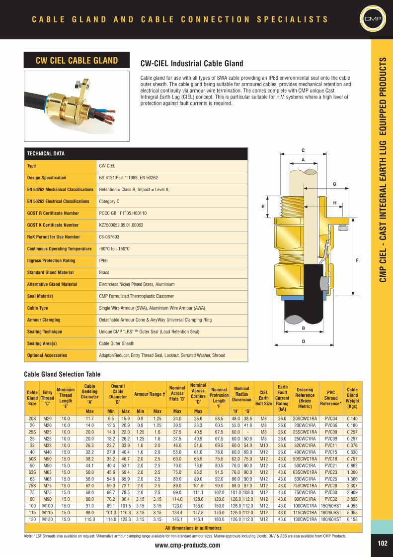
CMPCIEL
-CAS
TINTEGR
ALEA
RTHLU
GEQ
UIPP
EDPR
ODUC
TS
www.cmp-products.com
CMP
Cable gland for use with all types of SWA cable providing an IP66 environmental seal onto the cableouter sheath. The cable gland being suitable for armoured cables, provides mechanical retention andelectrical continuity via armour wire termination. The comes complete with CMP unique CastIntregral Earth Lug (CIEL) concept. This is particular suitable for H.V, systems where a high level ofprotection against fault currents is required.
CW-CIEL Industrial Cable GlandCW CIEL CABLE GLAND
AA
CC
HH
GG
EE
BB
DD
FF
Cable Gland Selection Table
Note: *LSF Shrouds also available on request. †Alternative armour clamping range available for non-standard armour sizes. Marine approvals including Lloyds, DNV & ABS are also available from CMP Products.
TECHNICAL DATA
Type CW CIEL
Design Specification BS 6121:Part 1:1989, EN 50262
EN 50262 Mechanical Classifications Retention = Class B, Impact = Level 8,
EN 50262 Electrical Classifications Category C
GOST R Certificate Number POCC GB. 05.H00110
GOST K Certificate Number KZ7500052.05.01.00063
RoK Permit for Use Number 08-067693
Continuous Operating Temperature -60°C to +150°C
Ingress Protection Rating IP66
Standard Gland Material Brass
Alternative Gland Material Electroless Nickel Plated Brass, Aluminium
Seal Material CMP Formulated Thermoplastic Elastomer
Cable Type Single Wire Armour (SWA), Aluminium Wire Armour (AWA)
Armour Clamping Detachable Armour Cone & AnyWay Universal Clamping Ring
Sealing Technique Unique CMP "LRS" ™ Outer Seal (Load Retention Seal)
Sealing Area(s) Cable Outer Sheath
Optional Accessories Adaptor/Reducer, Entry Thread Seal, Locknut, Serrated Washer, Shroud
LLU
CableGlandSize
EntryThread‘C’
MinimumThreadLength‘E’
CableBeddingDiameter
‘A’
OverallCable
DiameterB’
Armour Range †NominalAcrossFlats ‘D’
NominalAcrossCorners‘D’
NominalProtrusionLength‘F’
NominalRadius
Dimension
CIELEarth
Bolt Size
EarthFaultCurrentRating(kA)
OrderingReference(BrassMetric)
PVCShroud
Reference*
CableGlandWeight(Kgs)
Max Min Max Min Max Max Max ‘H’ ‘G’
20S M20 10.0 11.7 9.5 15.9 0.9 1.25 24.0 26.6 58.5 48.0 38.6 M8 26.0 20SCWC1RA PVC04 0.14020 M20 10.0 14.0 12.5 20.9 0.9 1.25 30.5 33.3 60.5 55.0 41.8 M8 26.0 20CWC1RA PVC06 0.18025S M25 10.0 20.0 14.0 22.0 1.25 1.6 37.5 40.5 67.5 60.0 - M8 26.0 25SCWC1RA PVC09 0.25725 M25 10.0 20.0 18.2 26.2 1.25 1.6 37.5 40.5 67.5 60.0 50.8 M8 26.0 25CWC1RA PVC09 0.25732 M32 10.0 26.3 23.7 33.9 1.6 2.0 46.0 51.0 69.5 60.0 54.0 M10 26.0 32CWC1RA PVC11 0.37640 M40 15.0 32.2 27.9 40.4 1.6 2.0 55.0 61.0 78.0 60.0 69.0 M12 26.0 40CWC1RA PVC15 0.63050S M50 15.0 38.2 35.2 46.7 2.0 2.5 60.0 66.5 75.5 62.0 75.0 M12 43.0 50SCWC1RA PVC18 0.75750 M50 15.0 44.1 40.4 53.1 2.0 2.5 70.0 78.6 80.5 76.0 80.0 M12 43.0 50CWC1RA PVC21 0.86263S M63 15.0 50.0 45.6 59.4 2.0 2.5 75.0 83.2 91.5 76.0 90.0 M12 43.0 63SCWC1RA PVC23 1.39063 M63 15.0 56.0 54.6 65.9 2.0 2.5 80.0 89.0 92.0 86.0 90.0 M12 43.0 63CWC1RA PVC25 1.36075S M75 15.0 62.0 59.0 72.1 2.0 2.5 89.0 101.6 99.0 88.0 97.0 M12 43.0 75SCWC1RA PVC28 2.30775 M75 15.0 68.0 66.7 78.5 2.0 2.5 99.0 111.1 102.0 101.0 108.0 M12 43.0 75CWC1RA PVC30 2.90990 M90 15.0 80.0 76.2 90.4 3.15 3.15 114.0 128.6 120.0 126.0 112.0 M12 43.0 90CWC1RA PVC32 3.858100 M100 15.0 91.0 89.1 101.5 3.15 3.15 123.0 136.0 150.0 126.0 112.0 M12 43.0 100CWC1RA 150/50HST 4.958115 M115 15.0 98.0 101.3 110.3 3.15 3.15 133.4 147.8 170.0 126.0 112.0 M12 43.0 115CWC1RA 180/60HST 5.058130 M130 15.0 115.0 114.0 123.3 3.15 3.15 146.1 146.1 180.0 126.0 112.0 M12 43.0 130CWC1RA 180/60HST 6.158
All dimensions in millimetres
C A B L E G L A N D A N D C A B L E C O N N E C T I O N S P E C I A L I S T S CMP
102
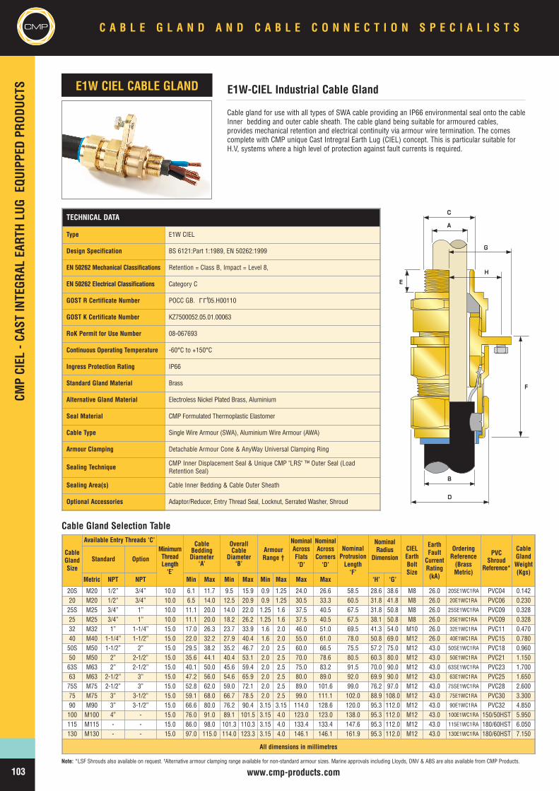
CMPCM
PCIEL
-CAS
TINTEGR
ALEA
RTHLU
GEQ
UIPP
EDPR
ODUC
TS
www.cmp-products.com
Cable gland for use with all types of SWA cable providing an IP66 environmental seal onto the cableInner bedding and outer cable sheath. The cable gland being suitable for armoured cables,provides mechanical retention and electrical continuity via armour wire termination. The comescomplete with CMP unique Cast Intregral Earth Lug (CIEL) concept. This is particular suitable forH.V, systems where a high level of protection against fault currents is required.
E1W-CIEL Industrial Cable GlandE1W CIEL CABLE GLAND
AA
CC
HH
GG
BB
DD
EE
FF
Cable Gland Selection Table
Note: *LSF Shrouds also available on request. †Alternative armour clamping range available for non-standard armour sizes. Marine approvals including Lloyds, DNV & ABS are also available from CMP Products.
TECHNICAL DATA
Type E1W CIEL
Design Specification BS 6121:Part 1:1989, EN 50262:1999
EN 50262 Mechanical Classifications Retention = Class B, Impact = Level 8,
EN 50262 Electrical Classifications Category C
GOST R Certificate Number POCC GB. 05.H00110
GOST K Certificate Number KZ7500052.05.01.00063
RoK Permit for Use Number 08-067693
Continuous Operating Temperature -60°C to +150°C
Ingress Protection Rating IP66
Standard Gland Material Brass
Alternative Gland Material Electroless Nickel Plated Brass, Aluminium
Seal Material CMP Formulated Thermoplastic Elastomer
Cable Type Single Wire Armour (SWA), Aluminium Wire Armour (AWA)
Armour Clamping Detachable Armour Cone & AnyWay Universal Clamping Ring
Sealing Technique CMP Inner Displacement Seal & Unique CMP "LRS" ™ Outer Seal (LoadRetention Seal)
Sealing Area(s) Cable Inner Bedding & Cable Outer Sheath
Optional Accessories Adaptor/Reducer, Entry Thread Seal, Locknut, Serrated Washer, Shroud
LLU
CableGlandSize
Available Entry Threads ‘C’MinimumThreadLength‘E’
CableBeddingDiameter
‘A’
OverallCable
Diameter‘B’
ArmourRange †
NominalAcrossFlats‘D’
NominalAcrossCorners‘D’
NominalProtrusionLength‘F’
NominalRadius
DimensionCIELEarthBoltSize
EarthFaultCurrentRating(kA)
OrderingReference(BrassMetric)
PVCShroud
Reference*
CableGlandWeight(Kgs)
Standard Option
Metric NPT NPT Min Max Min Max Min Max Max Max ‘H’ ‘G’
20S M20 1/2” 3/4” 10.0 6.1 11.7 9.5 15.9 0.9 1.25 24.0 26.6 58.5 28.6 38.6 M8 26.0 20SE1WC1RA PVC04 0.14220 M20 1/2” 3/4” 10.0 6.5 14.0 12.5 20.9 0.9 1.25 30.5 33.3 60.5 31.8 41.8 M8 26.0 20E1WC1RA PVC06 0.23025S M25 3/4” 1” 10.0 11.1 20.0 14.0 22.0 1.25 1.6 37.5 40.5 67.5 31.8 50.8 M8 26.0 25SE1WC1RA PVC09 0.32825 M25 3/4” 1” 10.0 11.1 20.0 18.2 26.2 1.25 1.6 37.5 40.5 67.5 38.1 50.8 M8 26.0 25E1WC1RA PVC09 0.32832 M32 1” 1-1/4” 15.0 17.0 26.3 23.7 33.9 1.6 2.0 46.0 51.0 69.5 41.3 54.0 M10 26.0 32E1WC1RA PVC11 0.47040 M40 1-1/4” 1-1/2” 15.0 22.0 32.2 27.9 40.4 1.6 2.0 55.0 61.0 78.0 50.8 69.0 M12 26.0 40E1WC1RA PVC15 0.78050S M50 1-1/2” 2” 15.0 29.5 38.2 35.2 46.7 2.0 2.5 60.0 66.5 75.5 57.2 75.0 M12 43.0 50SE1WC1RA PVC18 0.96050 M50 2” 2-1/2” 15.0 35.6 44.1 40.4 53.1 2.0 2.5 70.0 78.6 80.5 60.3 80.0 M12 43.0 50E1WC1RA PVC21 1.15063S M63 2” 2-1/2” 15.0 40.1 50.0 45.6 59.4 2.0 2.5 75.0 83.2 91.5 70.0 90.0 M12 43.0 63SE1WC1RA PVC23 1.70063 M63 2-1/2” 3” 15.0 47.2 56.0 54.6 65.9 2.0 2.5 80.0 89.0 92.0 69.9 90.0 M12 43.0 63E1WC1RA PVC25 1.65075S M75 2-1/2” 3” 15.0 52.8 62.0 59.0 72.1 2.0 2.5 89.0 101.6 99.0 76.2 97.0 M12 43.0 75SE1WC1RA PVC28 2.60075 M75 3” 3-1/2” 15.0 59.1 68.0 66.7 78.5 2.0 2.5 99.0 111.1 102.0 88.9 108.0 M12 43.0 75E1WC1RA PVC30 3.30090 M90 3” 3-1/2” 15.0 66.6 80.0 76.2 90.4 3.15 3.15 114.0 128.6 120.0 95.3 112.0 M12 43.0 90E1WC1RA PVC32 4.850100 M100 4” - 15.0 76.0 91.0 89.1 101.5 3.15 4.0 123.0 123.0 138.0 95.3 112.0 M12 43.0 100E1WC1RA 150/50HST 5.950115 M115 - - 15.0 86.0 98.0 101.3 110.3 3.15 4.0 133.4 133.4 147.6 95.3 112.0 M12 43.0 115E1WC1RA 180/60HST 6.050130 M130 - - 15.0 97.0 115.0 114.0 123.3 3.15 4.0 146.1 146.1 161.9 95.3 112.0 M12 43.0 130E1WC1RA 180/60HST 7.150
All dimensions in millimetres
C A B L E G L A N D A N D C A B L E C O N N E C T I O N S P E C I A L I S T SCMP
103
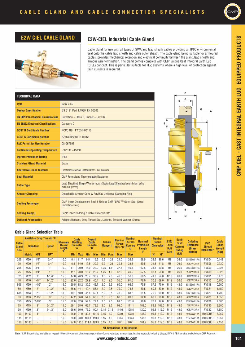
CableGlandSize
Available Entry Threads ‘C’MinimumThreadLength‘E’
CableBeddingDiameter
‘A’
OverallCable
Diameter‘B’
ArmourRange †
NominalAcrossFlats ‘D’
NominalAcrossCorners‘D’
NominalProtrusionLength‘F’
NominalRadius
DimensionCIELEarthBoltSize
EarthFaultCurrentRating(kA)
OrderingReference(BrassMetric)
PVCShroud
Reference*
CableGlandWeight(Kgs)
Standard Option
Metric NPT NPT Min Max Min Max Min Max Max Max ‘H’ ‘G’
20S M20 1/2” 3/4” 10.0 6.1 11.7 9.5 15.9 0.9 1.25 24.0 26.6 58.5 28.6 38.6 M8 26.0 20SE2WC1RA PVC04 0.14220 M20 1/2” 3/4” 10.0 6.5 14.0 12.5 20.9 0.9 1.25 30.5 33.3 60.5 31.8 41.8 M8 26.0 20E2WC1RA PVC06 0.23025S M25 3/4” 1” 10.0 11.1 20.0 14.0 22.0 1.25 1.6 37.5 40.5 67.5 31.8 50.8 M8 26.0 25SE2WC1RA PVC09 0.32825 M25 3/4” 1” 10.0 11.1 20.0 18.2 26.2 1.25 1.6 37.5 40.5 67.5 38.1 50.8 M8 26.0 25E2WC1RA PVC09 0.32832 M32 1” 1-1/4” 15.0 17.0 26.3 23.7 33.9 1.6 2.0 46.0 51.0 69.5 41.3 54.0 M10 26.0 32E2WC1RA PVC11 0.47040 M40 1-1/4” 1-1/2” 15.0 22.0 32.2 27.9 40.4 1.6 2.0 55.0 61.0 78.0 50.8 69.0 M12 26.0 40E2WC1RA PVC15 0.78050S M50 1-1/2” 2” 15.0 29.5 38.2 35.2 46.7 2.0 2.5 60.0 66.5 75.5 57.2 75.0 M12 43.0 50SE2WC1RA PVC18 0.96050 M50 2” 2-1/2” 15.0 35.6 44.1 40.4 53.1 2.0 2.5 70.0 78.6 80.5 60.3 80.0 M12 43.0 50E2WC1RA PVC21 1.15063S M63 2” 2-1/2” 15.0 40.1 50.0 45.6 59.4 2.0 2.5 75.0 83.2 91.5 70.0 90.0 M12 43.0 63SE2WC1RA PVC23 1.70063 M63 2-1/2” 3” 15.0 47.2 56.0 54.6 65.9 2.0 2.5 80.0 89.0 92.0 69.9 90.0 M12 43.0 63E2WC1RA PVC25 1.65075S M75 2-1/2” 3” 15.0 52.8 62.0 59.0 72.1 2.0 2.5 89.0 101.6 99.0 76.2 97.0 M12 43.0 75SE2WC1RA PVC28 2.60075 M75 3” 3-1/2” 15.0 59.1 68.0 66.7 78.5 2.0 2.5 99.0 111.1 102.0 88.9 108.0 M12 43.0 75E2WC1RA PVC30 3.30090 M90 3” 3-1/2” 15.0 66.6 80.0 76.2 90.4 3.15 3.15 114.0 128.6 120.0 95.3 112.0 M12 43.0 90E2WC1RA PVC32 4.850100 M100 4” - 15.0 76.0 91.0 89.1 101.5 3.15 4.0 123.0 123.0 138.0 95.3 112.0 M12 43.0 100E2WC1RA 150/50HST 5.950115 M115 - - 15.0 86.0 98.0 101.3 110.3 3.15 4.0 133.4 133.4 147.6 95.3 112.0 M12 43.0 115E2WC1RA 180/60HST 6.050130 M130 - - 15.0 97.0 115.0 114.0 123.3 3.15 4.0 146.1 146.1 161.9 95.3 112.0 M12 43.0 130E2WC1RA 180/60HST 7.150
All dimensions in millimetres
CMPCIEL
-CAS
TINTEGR
ALEA
RTHLU
GEQ
UIPP
EDPR
ODUC
TS
www.cmp-products.com
CMP
Cable gland for use with all types of SWA and lead sheath cables providing an IP66 environmentalseal onto the cable lead sheath and cable outer sheath. The cable gland being suitable for armouredcables, provides mechanical retention and electrical continuity between the gland,lead sheath andarmour wire termination. The gland comes complete with CMP unique Cast Intregral Earth Lug(CIEL) concept. This is particular suitable for H.V, systems where a high level of protection againstfault currents is required.
E2W-CIEL Industrial Cable GlandE2W CIEL CABLE GLAND
BB
DD
AA
CC
HH
GG
EE
FF
Cable Gland Selection Table
Note: *LSF Shrouds also available on request. †Alternative armour clamping range available for non-standard armour sizes. Marine approvals including Lloyds, DNV & ABS are also available from CMP Products.
TECHNICAL DATA
Type E2W CIEL
Design Specification BS 6121:Part 1:1989, EN 50262
EN 50262 Mechanical Classifications Retention = Class B, Impact = Level 8,
EN 50262 Electrical Classifications Category C
GOST R Certificate Number POCC GB. 05.H00110
GOST K Certificate Number KZ7500052.05.01.00063
RoK Permit for Use Number 08-067693
Continuous Operating Temperature -60°C to +150°C
Ingress Protection Rating IP66
Standard Gland Material Brass
Alternative Gland Material Electroless Nickel Plated Brass, Aluminium
Seal Material CMP Formulated Thermoplastic Elastomer
Cable Type Lead Sheathed Single Wire Armour (SWA),Lead Sheathed Aluminium WireArmour (AWA)
Armour Clamping Detachable Armour Cone & AnyWay Universal Clamping Ring
Sealing Technique CMP Inner Displacement Seal & Unique CMP "LRS" ™ Outer Seal (LoadRetention Seal)
Sealing Area(s) Cable Inner Bedding & Cable Outer Sheath
Optional Accessories Adaptor/Reducer, Entry Thread Seal, Locknut, Serrated Washer, Shroud
LLU
C A B L E G L A N D A N D C A B L E C O N N E C T I O N S P E C I A L I S T S CMP
104
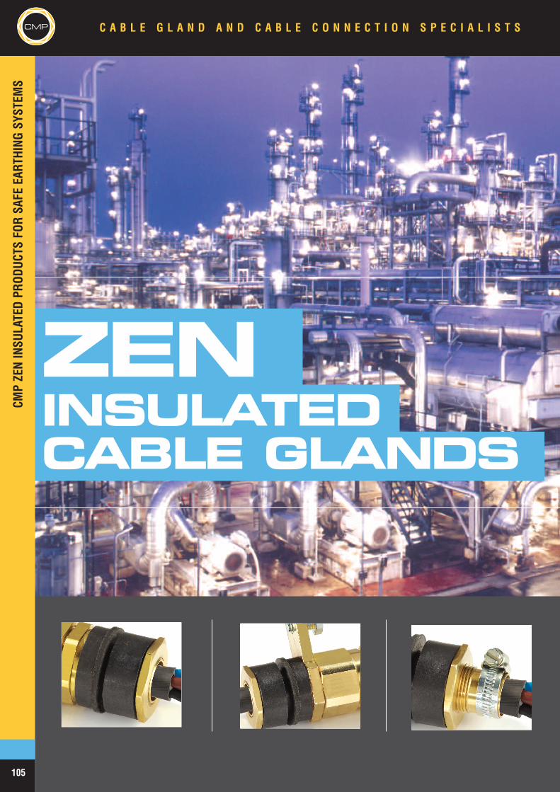
CMP
ZENINSULATEDCABLE GLANDS
C A B L E G L A N D A N D C A B L E C O N N E C T I O N S P E C I A L I S T SCMP
105
CMPZENINSU
LATEDPR
ODUC
TSFO
RSA
FEEA
RTHING
SYST
EMS
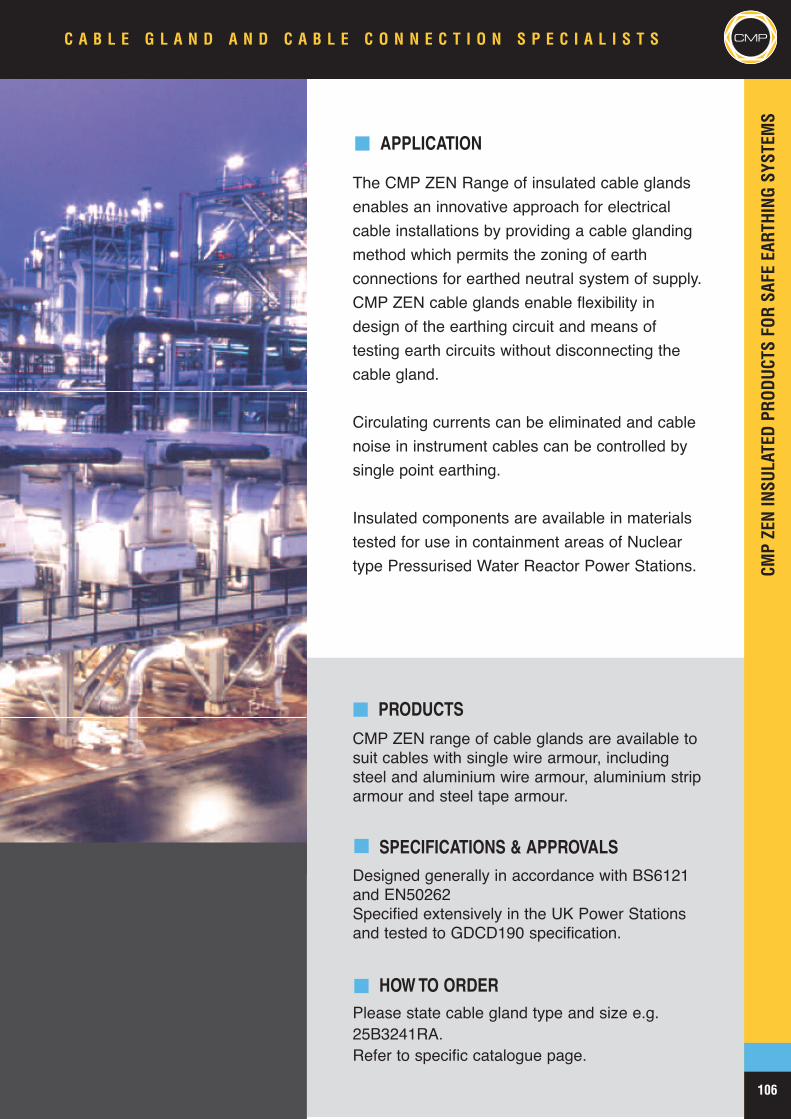
CMPZENINSU
LATEDPR
ODUC
TSFO
RSA
FEEA
RTHING
SYST
EMS
106
CMP
APPLICATION
The CMP ZEN Range of insulated cable glandsenables an innovative approach for electricalcable installations by providing a cable glandingmethod which permits the zoning of earthconnections for earthed neutral system of supply.CMP ZEN cable glands enable flexibility indesign of the earthing circuit and means oftesting earth circuits without disconnecting thecable gland.
Circulating currents can be eliminated and cablenoise in instrument cables can be controlled bysingle point earthing.
Insulated components are available in materialstested for use in containment areas of Nucleartype Pressurised Water Reactor Power Stations.
PRODUCTS
CMP ZEN range of cable glands are available tosuit cables with single wire armour, includingsteel and aluminium wire armour, aluminium striparmour and steel tape armour.
SPECIFICATIONS & APPROVALSDesigned generally in accordance with BS6121and EN50262Specified extensively in the UK Power Stationsand tested to GDCD190 specification.
HOW TO ORDERPlease state cable gland type and size e.g.25B3241RA.Refer to specific catalogue page.
C A B L E G L A N D A N D C A B L E C O N N E C T I O N S P E C I A L I S T S CMP
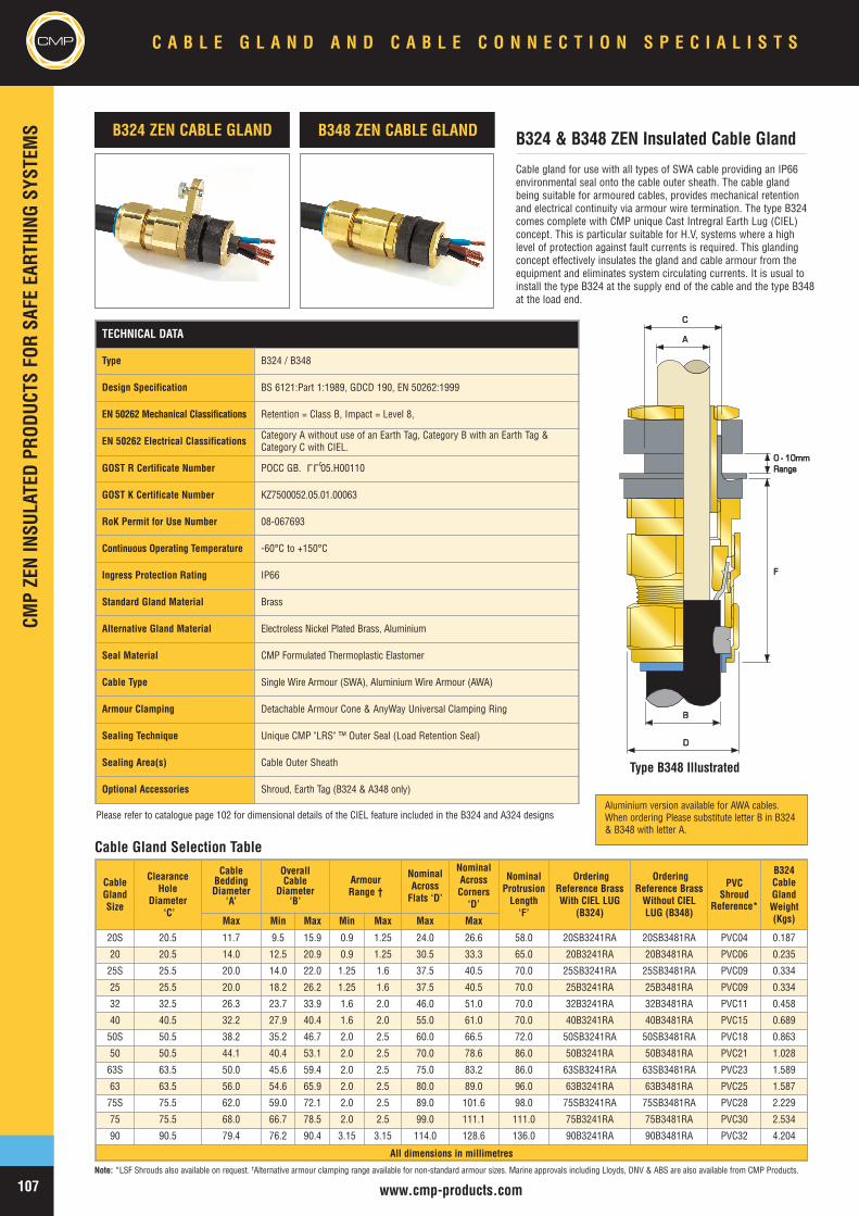
CMP
www.cmp-products.com
Cable gland for use with all types of SWA cable providing an IP66environmental seal onto the cable outer sheath. The cable glandbeing suitable for armoured cables, provides mechanical retentionand electrical continuity via armour wire termination. The type B324comes complete with CMP unique Cast Intregral Earth Lug (CIEL)concept. This is particular suitable for H.V, systems where a highlevel of protection against fault currents is required. This glandingconcept effectively insulates the gland and cable armour from theequipment and eliminates system circulating currents. It is usual toinstall the type B324 at the supply end of the cable and the type B348at the load end.
B324 ZEN CABLE GLAND
AA
CC
0 - 10mm0 - 10mmRangeRange
BB
DD
FF
Cable Gland Selection Table
Note: *LSF Shrouds also available on request. †Alternative armour clamping range available for non-standard armour sizes. Marine approvals including Lloyds, DNV & ABS are also available from CMP Products.
B324 & B348 ZEN Insulated Cable GlandB348 ZEN CABLE GLAND
TECHNICAL DATA
Type B324 / B348
Design Specification BS 6121:Part 1:1989, GDCD 190, EN 50262:1999
EN 50262 Mechanical Classifications Retention = Class B, Impact = Level 8,
EN 50262 Electrical Classifications Category A without use of an Earth Tag, Category B with an Earth Tag &Category C with CIEL.
GOST R Certificate Number POCC GB. 05.H00110
GOST K Certificate Number KZ7500052.05.01.00063
RoK Permit for Use Number 08-067693
Continuous Operating Temperature -60°C to +150°C
Ingress Protection Rating IP66
Standard Gland Material Brass
Alternative Gland Material Electroless Nickel Plated Brass, Aluminium
Seal Material CMP Formulated Thermoplastic Elastomer
Cable Type Single Wire Armour (SWA), Aluminium Wire Armour (AWA)
Armour Clamping Detachable Armour Cone & AnyWay Universal Clamping Ring
Sealing Technique Unique CMP "LRS" ™ Outer Seal (Load Retention Seal)
Sealing Area(s) Cable Outer Sheath
Optional Accessories Shroud, Earth Tag (B324 & A348 only)
LLU
CableGlandSize
ClearanceHole
Diameter‘C’
CableBeddingDiameter
‘A’
OverallCable
Diameter‘B’
ArmourRange †
NominalAcrossFlats ‘D’
NominalAcrossCorners‘D’
NominalProtrusionLength‘F’
OrderingReference BrassWith CIEL LUG
(B324)
OrderingReference BrassWithout CIELLUG (B348)
PVCShroud
Reference*
B324CableGlandWeight(Kgs)Max Min Max Min Max Max Max
20S 20.5 11.7 9.5 15.9 0.9 1.25 24.0 26.6 58.0 20SB3241RA 20SB3481RA PVC04 0.187
20 20.5 14.0 12.5 20.9 0.9 1.25 30.5 33.3 65.0 20B3241RA 20B3481RA PVC06 0.235
25S 25.5 20.0 14.0 22.0 1.25 1.6 37.5 40.5 70.0 25SB3241RA 25SB3481RA PVC09 0.334
25 25.5 20.0 18.2 26.2 1.25 1.6 37.5 40.5 70.0 25B3241RA 25B3481RA PVC09 0.334
32 32.5 26.3 23.7 33.9 1.6 2.0 46.0 51.0 70.0 32B3241RA 32B3481RA PVC11 0.458
40 40.5 32.2 27.9 40.4 1.6 2.0 55.0 61.0 70.0 40B3241RA 40B3481RA PVC15 0.689
50S 50.5 38.2 35.2 46.7 2.0 2.5 60.0 66.5 72.0 50SB3241RA 50SB3481RA PVC18 0.863
50 50.5 44.1 40.4 53.1 2.0 2.5 70.0 78.6 86.0 50B3241RA 50B3481RA PVC21 1.028
63S 63.5 50.0 45.6 59.4 2.0 2.5 75.0 83.2 86.0 63SB3241RA 63SB3481RA PVC23 1.589
63 63.5 56.0 54.6 65.9 2.0 2.5 80.0 89.0 96.0 63B3241RA 63B3481RA PVC25 1.587
75S 75.5 62.0 59.0 72.1 2.0 2.5 89.0 101.6 98.0 75SB3241RA 75SB3481RA PVC28 2.229
75 75.5 68.0 66.7 78.5 2.0 2.5 99.0 111.1 111.0 75B3241RA 75B3481RA PVC30 2.534
90 90.5 79.4 76.2 90.4 3.15 3.15 114.0 128.6 136.0 90B3241RA 90B3481RA PVC32 4.204
All dimensions in millimetres
Type B348 Illustrated
CMP C A B L E G L A N D A N D C A B L E C O N N E C T I O N S P E C I A L I S T S
107
CMPZENINSU
LATEDPR
ODUC
TSFO
RSA
FEEA
RTHING
SYST
EMS
Please refer to catalogue page 102 for dimensional details of the CIEL feature included in the B324 and A324 designsAluminium version available for AWA cables.When ordering Please substitute letter B in B324& B348 with letter A.
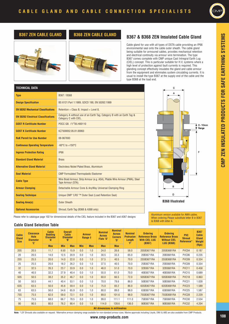
www.cmp-products.com
CMP
Note: *LSF Shrouds also available on request. †Alternative armour clamping range available for non-standard armour sizes. Marine approvals including Lloyds, DNV & ABS are also available from CMP Products.
Cable gland for use with all types of DSTA cable providing an IP66environmental seal onto the cable outer sheath. The cable glandbeing suitable for armoured cables, provides mechanical retentionand electrical continuity via armour wire termination. The typeB367 comes complete with CMP unique Cast Intregral Earth Lug(CIEL) concept. This is particular suitable for H.V, systems where ahigh level of protection against fault currents is required. Thisglanding concept effectively insulates the gland and cable armourfrom the equipment and eliminates system circulating currents. It isusual to install the type B367 at the supply end of the cable and thetype B368 at the load end.
B367 ZEN CABLE GLAND
AA
CC
BB
DD
FF
0 - 10mm0 - 10mmRangeRange
Cable Gland Selection Table
B367 & B368 ZEN Insulated Cable GlandB368 ZEN CABLE GLAND
TECHNICAL DATA
Type B367 / B368
Design Specification BS 6121:Part 1:1989, GDCD 190, EN 50262:1999
EN 50262 Mechanical Classifications Retention = Class B, Impact = Level 8,
EN 50262 Electrical Classifications Category A without use of an Earth Tag, Category B with an Earth Tag &Category C with CIEL.
GOST R Certificate Number POCC GB. 05.H00110
GOST K Certificate Number KZ7500052.05.01.00063
RoK Permit for Use Number 08-067693
Continuous Operating Temperature -60°C to +150°C
Ingress Protection Rating IP66
Standard Gland Material Brass
Alternative Gland Material Electroless Nickel Plated Brass, Aluminium
Seal Material CMP Formulated Thermoplastic Elastomer
Cable Type Wire Braid Armour, Strip Armour (e.g. ASA), Pliable Wire Armour (PWA), SteelTape Armour (STA).
Armour Clamping Detachable Armour Cone & AnyWay Universal Clamping Ring
Sealing Technique Unique CMP "LRS" ™ Outer Seal (Load Retention Seal)
Sealing Area(s) Outer Sheath
Optional Accessories Shroud, Earth Tag (B368 & A368 only)
LLU
CableGlandSize
ClearanceHole
Diameter‘C’
CableBeddingDiameter
‘A’
OverallCable
Diameter‘B’
ArmourRange †
NominalAcrossFlats ‘D’
NominalAcrossCorners‘D’
NominalProtrusionLength‘F’
OrderingReference BrassWith CIEL LUG
(B367)
OrderingReference BrassWithout CIELLUG (B368)
PVCShroud
Reference*
B367CableGlandWeight(Kgs)Max Min Max Min Max Max Max
20S 20.5 11.7 9.50 15.9 0.0 1.0 24.0 26.6 58.0 20SB3671RA 20SB3681RA PVC04 0.187
20 20.5 14.0 12.5 20.9 0.0 1.0 30.5 33.3 65.0 20B3671RA 20B3681RA PVC06 0.235
25S 25.5 20.0 14.0 22.0 0.0 1.0 37.5 40.5 70.0 25SB3671RA 25SB3681RA PVC09 0.334
25 25.5 20.0 18.2 26.2 0.0 1.0 37.5 40.5 70.0 25B3671RA 25B3681RA PVC09 0.334
32 32.5 26.3 23.7 33.9 0.0 1.0 46.0 51.0 70.0 32B3671RA 32B3681RA PVC11 0.458
40 40.5 32.2 27.9 40.4 0.0 1.0 55.0 61.0 70.0 40B3671RA 40B3681RA PVC15 0.689
50S 50.5 38.2 35.2 46.7 0.0 1.0 60.0 66.5 72.0 50SB3671RA 50SB3681RA PVC18 0.863
50 50.5 44.1 40.4 53.1 0.0 1.0 70.0 78.6 86.0 50B3671RA 50B3681RA PVC21 1.028
63S 63.5 50.0 45.6 59.4 0.0 1.0 75.0 83.2 86.0 63SB3671RA 63SB3681RA PVC23 1.589
63 63.5 56.0 54.6 65.9 0.0 1.0 80.0 89.0 98.0 63B3671RA 63B3681RA PVC25 1.587
75S 75.5 62.0 59.0 72.1 0.0 1.0 89.0 101.6 98.0 75SB3671RA 75SB3681RA PVC28 2.229
75 75.5 68.0 66.7 78.5 0.0 1.0 99.0 111.1 111.0 75B3671RA 75B3681RA PVC30 2.534
90 90.5 80.0 76.2 90.4 0.0 1.6 114.0 128.6 136.0 90B3671RA 90B3681RA PVC32 4.204
All dimensions in millimetres
B368 Illustrated
C A B L E G L A N D A N D C A B L E C O N N E C T I O N S P E C I A L I S T S CMP
108
CMPZENINSU
LATEDPR
ODUC
TSFO
RSA
FEEA
RTHING
SYST
EMS
Please refer to catalogue page 102 for dimensional details of the CIEL feature included in the B367 and A367 designsAluminium version available for AWA cables.When ordering Please substitute letter B in B367& B368 with letter A.
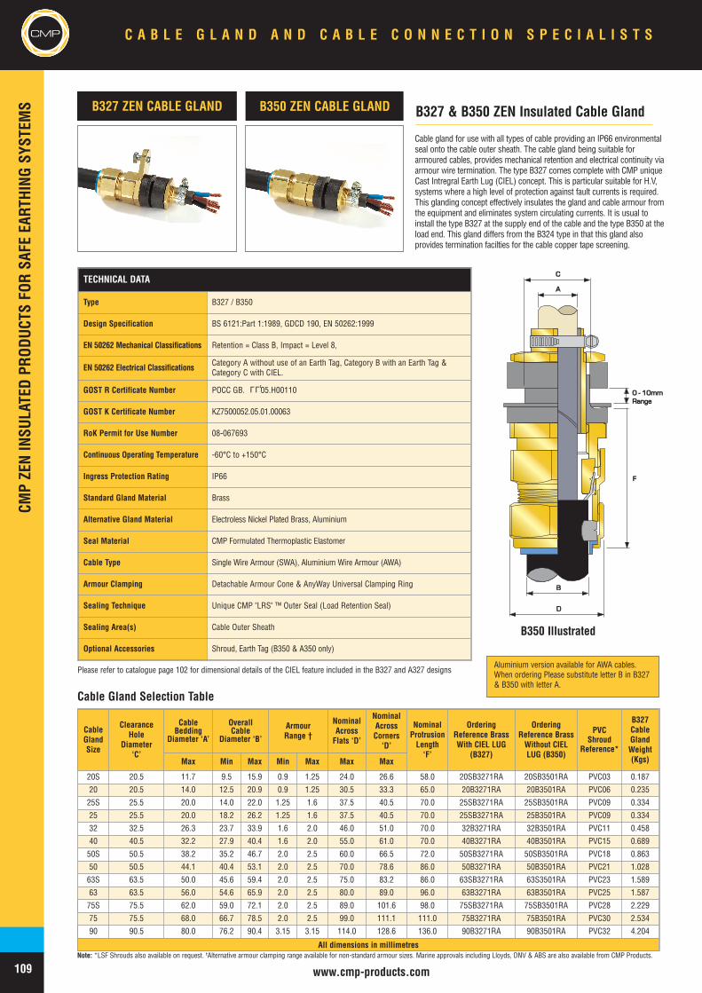
CMPCM
PZENINSU
LATEDPR
ODUC
TSFO
RSA
FEEA
RTHING
SYST
EMS
C A B L E G L A N D A N D C A B L E C O N N E C T I O N S P E C I A L I S T S
109 www.cmp-products.com
CMP
Note: *LSF Shrouds also available on request. †Alternative armour clamping range available for non-standard armour sizes. Marine approvals including Lloyds, DNV & ABS are also available from CMP Products.
Cable gland for use with all types of cable providing an IP66 environmentalseal onto the cable outer sheath. The cable gland being suitable forarmoured cables, provides mechanical retention and electrical continuity viaarmour wire termination. The type B327 comes complete with CMP uniqueCast Intregral Earth Lug (CIEL) concept. This is particular suitable for H.V,systems where a high level of protection against fault currents is required.This glanding concept effectively insulates the gland and cable armour fromthe equipment and eliminates system circulating currents. It is usual toinstall the type B327 at the supply end of the cable and the type B350 at theload end. This gland differs from the B324 type in that this gland alsoprovides termination facilties for the cable copper tape screening.
B327 ZEN CABLE GLAND
AA
CC
BB
DD
FF
0 - 10mm0 - 10mmRangeRange
Cable Gland Selection Table
B327 & B350 ZEN Insulated Cable GlandB350 ZEN CABLE GLAND
TECHNICAL DATA
Type B327 / B350
Design Specification BS 6121:Part 1:1989, GDCD 190, EN 50262:1999
EN 50262 Mechanical Classifications Retention = Class B, Impact = Level 8,
EN 50262 Electrical Classifications Category A without use of an Earth Tag, Category B with an Earth Tag &Category C with CIEL.
GOST R Certificate Number POCC GB. 05.H00110
GOST K Certificate Number KZ7500052.05.01.00063
RoK Permit for Use Number 08-067693
Continuous Operating Temperature -60°C to +150°C
Ingress Protection Rating IP66
Standard Gland Material Brass
Alternative Gland Material Electroless Nickel Plated Brass, Aluminium
Seal Material CMP Formulated Thermoplastic Elastomer
Cable Type Single Wire Armour (SWA), Aluminium Wire Armour (AWA)
Armour Clamping Detachable Armour Cone & AnyWay Universal Clamping Ring
Sealing Technique Unique CMP "LRS" ™ Outer Seal (Load Retention Seal)
Sealing Area(s) Cable Outer Sheath
Optional Accessories Shroud, Earth Tag (B350 & A350 only)
LLU
B350 Illustrated
CableGlandSize
ClearanceHole
Diameter‘C’
CableBedding
Diameter ‘A’
OverallCable
Diameter ‘B’
ArmourRange †
NominalAcrossFlats ‘D’
NominalAcrossCorners‘D’
NominalProtrusionLength‘F’
OrderingReference BrassWith CIEL LUG
(B327)
OrderingReference BrassWithout CIELLUG (B350)
PVCShroud
Reference*
B327CableGlandWeight(Kgs)Max Min Max Min Max Max Max
20S 20.5 11.7 9.5 15.9 0.9 1.25 24.0 26.6 58.0 20SB3271RA 20SB3501RA PVC03 0.187
20 20.5 14.0 12.5 20.9 0.9 1.25 30.5 33.3 65.0 20B3271RA 20B3501RA PVC06 0.235
25S 25.5 20.0 14.0 22.0 1.25 1.6 37.5 40.5 70.0 25SB3271RA 25SB3501RA PVC09 0.334
25 25.5 20.0 18.2 26.2 1.25 1.6 37.5 40.5 70.0 25SB3271RA 25B3501RA PVC09 0.334
32 32.5 26.3 23.7 33.9 1.6 2.0 46.0 51.0 70.0 32B3271RA 32B3501RA PVC11 0.458
40 40.5 32.2 27.9 40.4 1.6 2.0 55.0 61.0 70.0 40B3271RA 40B3501RA PVC15 0.689
50S 50.5 38.2 35.2 46.7 2.0 2.5 60.0 66.5 72.0 50SB3271RA 50SB3501RA PVC18 0.863
50 50.5 44.1 40.4 53.1 2.0 2.5 70.0 78.6 86.0 50B3271RA 50B3501RA PVC21 1.028
63S 63.5 50.0 45.6 59.4 2.0 2.5 75.0 83.2 86.0 63SB3271RA 63S3501RA PVC23 1.589
63 63.5 56.0 54.6 65.9 2.0 2.5 80.0 89.0 96.0 63B3271RA 63B3501RA PVC25 1.587
75S 75.5 62.0 59.0 72.1 2.0 2.5 89.0 101.6 98.0 75SB3271RA 75SB3501RA PVC28 2.229
75 75.5 68.0 66.7 78.5 2.0 2.5 99.0 111.1 111.0 75B3271RA 75B3501RA PVC30 2.534
90 90.5 80.0 76.2 90.4 3.15 3.15 114.0 128.6 136.0 90B3271RA 90B3501RA PVC32 4.204
All dimensions in millimetres
Please refer to catalogue page 102 for dimensional details of the CIEL feature included in the B327 and A327 designsAluminium version available for AWA cables.When ordering Please substitute letter B in B327& B350 with letter A.
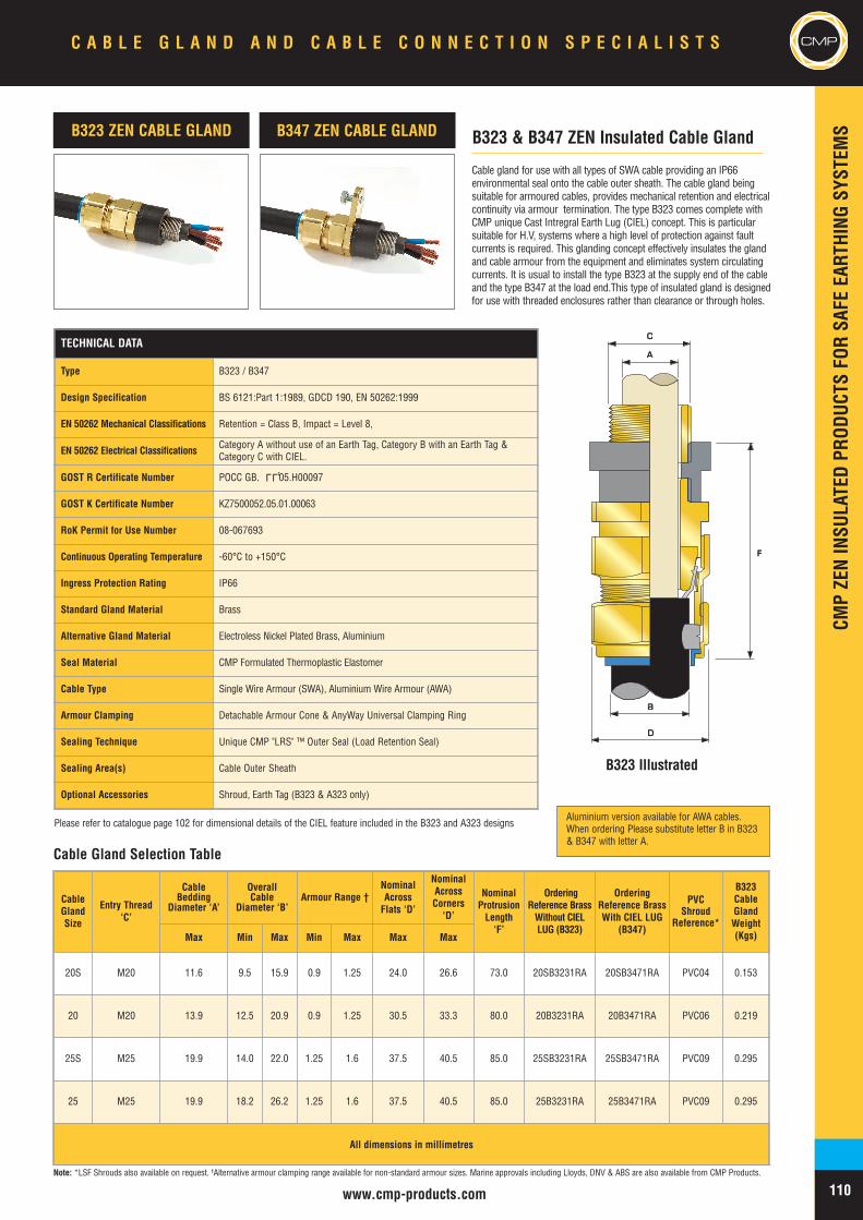
CMPZENINSU
LATEDPR
ODUC
TSFO
RSA
FEEA
RTHING
SYST
EMS
110www.cmp-products.com
CMPCMP
Note: *LSF Shrouds also available on request. †Alternative armour clamping range available for non-standard armour sizes. Marine approvals including Lloyds, DNV & ABS are also available from CMP Products.
Cable gland for use with all types of SWA cable providing an IP66environmental seal onto the cable outer sheath. The cable gland beingsuitable for armoured cables, provides mechanical retention and electricalcontinuity via armour termination. The type B323 comes complete withCMP unique Cast Intregral Earth Lug (CIEL) concept. This is particularsuitable for H.V, systems where a high level of protection against faultcurrents is required. This glanding concept effectively insulates the glandand cable armour from the equipment and eliminates system circulatingcurrents. It is usual to install the type B323 at the supply end of the cableand the type B347 at the load end.This type of insulated gland is designedfor use with threaded enclosures rather than clearance or through holes.
B323 ZEN CABLE GLAND
AA
CC
BB
DD
FF
Cable Gland Selection Table
B323 & B347 ZEN Insulated Cable GlandB347 ZEN CABLE GLAND
TECHNICAL DATA
Type B323 / B347
Design Specification BS 6121:Part 1:1989, GDCD 190, EN 50262:1999
EN 50262 Mechanical Classifications Retention = Class B, Impact = Level 8,
EN 50262 Electrical Classifications Category A without use of an Earth Tag, Category B with an Earth Tag &Category C with CIEL.
GOST R Certificate Number POCC GB. 05.H00097
GOST K Certificate Number KZ7500052.05.01.00063
RoK Permit for Use Number 08-067693
Continuous Operating Temperature -60°C to +150°C
Ingress Protection Rating IP66
Standard Gland Material Brass
Alternative Gland Material Electroless Nickel Plated Brass, Aluminium
Seal Material CMP Formulated Thermoplastic Elastomer
Cable Type Single Wire Armour (SWA), Aluminium Wire Armour (AWA)
Armour Clamping Detachable Armour Cone & AnyWay Universal Clamping Ring
Sealing Technique Unique CMP "LRS" ™ Outer Seal (Load Retention Seal)
Sealing Area(s) Cable Outer Sheath
Optional Accessories Shroud, Earth Tag (B323 & A323 only)
LLU
CableGlandSize
Entry Thread‘C’
CableBedding
Diameter ‘A’
OverallCable
Diameter ‘B’Armour Range †
NominalAcrossFlats ‘D’
NominalAcrossCorners‘D’
NominalProtrusionLength‘F’
OrderingReference BrassWithout CIELLUG (B323)
OrderingReference BrassWith CIEL LUG
(B347)
PVCShroud
Reference*
B323CableGlandWeight(Kgs)Max Min Max Min Max Max Max
20S M20 11.6 9.5 15.9 0.9 1.25 24.0 26.6 73.0 20SB3231RA 20SB3471RA PVC04 0.153
20 M20 13.9 12.5 20.9 0.9 1.25 30.5 33.3 80.0 20B3231RA 20B3471RA PVC06 0.219
25S M25 19.9 14.0 22.0 1.25 1.6 37.5 40.5 85.0 25SB3231RA 25SB3471RA PVC09 0.295
25 M25 19.9 18.2 26.2 1.25 1.6 37.5 40.5 85.0 25B3231RA 25B3471RA PVC09 0.295
All dimensions in millimetres
B323 Illustrated
C A B L E G L A N D A N D C A B L E C O N N E C T I O N S P E C I A L I S T S
Please refer to catalogue page 102 for dimensional details of the CIEL feature included in the B323 and A323 designsAluminium version available for AWA cables.When ordering Please substitute letter B in B323& B347 with letter A.
IEC Ex & ATEXHAZARDOUSAREA CABLEGLANDS
CMPHA
ZARD
OUSAR
EAPR
ODUC
TSCMP C A B L E G L A N D A N D C A B L E C O N N E C T I O N S P E C I A L I S T S
111

CMPHA
ZARD
OUSAR
EAPR
ODUC
TS
112
C A B L E G L A N D A N D C A B L E C O N N E C T I O N S P E C I A L I S T S CMP
APPLICATION
The CMP range of IEC Ex & ATEX certified hazardousarea cable glands offers solutions which are highly costeffective in their design and installation process. The CMPphilosophy of delivering client and end user specificrequirements can be seen from a number of significantdevelopments in this range. Given the level of experiencegained in this field CMP is able to provide a high degree oftechnical support and advice on the selection and use ofcable glands in hazardous area applications.
PRODUCTS
Triple Certified cable gland options for all types of cablewith Ex d IIC, Ex e II and Ex nR II forms of protection,
SPECIFICATIONS & APPROVALS
Derived from the BS6121 standard which was the original‘flameproof’ standard for cable glandsCMP hazardous area cable glands comply with a number ofinternational standards including theEuropean Normatives (EN 60079 series), IEC (IEC 60079series) UL & CSA (UL 514B, UL 2225).
Multiple certification including ATEX, IEC Ex, GOST R,GOST K, CSA, UL, and INMETRO enables the possibilityof selecting fewer standard products for more globalsituations. Some solutions in the standard CMP hazardousarea range offer Bi-code approvals allowing theirdeployment under both IEC & NEC installation codes ofpractice.
TESTING
CMP Products offers hazardous area cable glands that aretested and certified to the latest international technicalstandards and through its programme of continuous productdevelopment always strives to maintain its certification inline with the very latest technical knowledge or state of theart, bringing global products to a world that can expect onlythe best from CMP in terms of compliance with up to datespecifications and standards.
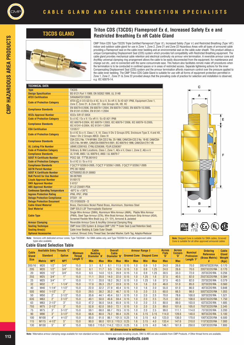
CMPCM
PHA
ZARD
OUSAR
EAPR
ODUC
TSC A B L E G L A N D A N D C A B L E C O N N E C T I O N S P E C I A L I S T S
113 www.cmp-products.com
CMP Triton CDS Type T3CDS Triple Certified Flameproof (Type 'd'), Increased Safety (Type 'e') and Restricted Breathing (Type ‘nR’)indoor and outdoor cable gland for use in Zone 1, Zone 2, Zone 21 and Zone 22 Hazardous Areas with all types of armoured cableproviding a Flameproof seal on the cable inner bedding and an environmental seal on the cable outer sheath. This product utilises aunique Compensating Displacement Seal (CDS) system which provides full compatibility with Restricted Breathing equipment. Thecable gland provides mechanical cable retention and electrical continuity via armour wire termination. A reversible armour cone andAnyWay universal clamping ring arrangement allows the cable to be easily disconnected from the equipment, for maintenance andchange out etc., and re-connected with the same consummate ease. This feature also facilitates remote make off procedures whenthe termination is to be conducted in confined spaces or in areas of restricted access. Separate tightening actions for the innerCompensating Displacement Seal (CDS) system and the armour termination affords maximum control over the pressure applied tothe cable inner bedding. The CMP Triton CDS Cable Gland is suitable for use with all forms of equipment protection permitted inZone 1, Zone 2 , Zone 21 & Zone 22 provided always that the prevailing code of practice for selection and installation is observed,e.g. IEC 60079-14.
TECHNICAL DATAType T3CDSDesign Specification BS 6121:Part 1:1989, EN 50262:1999, UL 514BATEX Certification SIRA06ATEX1283X
Code of Protection Category ATEX II 2/3 GD Ex d IIC, Ex e II, Ex nR II, Ex tD A21 IP66, Equipment Zone 1,Zone 2, Zone 21, & Zone 22 - Gas Groups IIA, IIB, IIC
Compliance Standards EN 60079-0:2006, EN 60079-1:2004, EN 60079-7:2003, EN 60079-15:2005,EN 61241-0:2004, EN 61241-1:2004
IECEx Approval Number IECEx SIR 07.005XCode of Protection Category Ex d IIC / Ex e II / Ex nR II / Ex tD A21 IP66
Compliance Standards IEC 60079-0:2004, IEC 60079-1:2003, IEC 60079-7:2006, IEC 60079-15:2005,IEC 61241-0:2004, IEC 61241-1:2004
CSA Certification 1310517
Code of Protection Category Ex d IIC Ex e II, Class I, II, III, Class II Div 2 Groups EFG, Enclosure Type 3, 4 and 4X,Class I Div 2 Groups ABCD, Class III
Compliance Standards CSA C22.2 No. 174-M1984, CSA C22.2 No. 25-1966, CAN/CSA-C22.2 No. 18-92, CAN/CSA-C22.2 No. 94-M91, CAN/CSA-E60079-0-2001, IEC 60079-0 1998, CAN/CSA-E79-7-95
UL Listing File Number UBWE.E200163, CYMJ.E256366, FDJR.E256367Code of Protection Category Ordinary & Wet Locations, Class I, Zone 1, AEx e II, Class I, Zone 2, AEx e IICompliance Standards UL 514B, ANSI / UL 60079-0, ANSI / UL 60079-7GOST R Certificate Number POCC GB. 05.B01912Code of Protection Category Ex d IIC U / Ex e II UCompliance Standards P 52350.0-2005, P 52350.1-2005, P 52350.7-2005GGTN Permit Number PPC 00-18262GOST K Certificate Number KZ7500052.05.01.00063RoK Permit for Use Number 08-067693Lloyds Approval Number 01/00172DNV Approval Number E-6157ABS Approval Number 01-LD 234401-PDAContinuous Operating Temperature -60°C to +130°CIngress Protection Rating IP66, IP67, IP68Deluge Protection Compliance DTS01 : 91Deluge Protection Document ITS 01005029 - DCable Gland Material Brass, Electroless Nickel Plated Brass, Aluminium, Stainless SteelSeal Material CMP SOLO LSF Thermoplastic Elastomer
Cable TypeSingle Wire Armour (SWA), Aluminium Wire Armour (AWA), Pliable Wire Armour(PWA), Steel Tape Armour (STA), Wire Braid Armour, Aluminium Strip Armour (ASA),Screened Flexible Wire Braid (e.g. CY / SY), Armored & Jacketed
Armour Clamping Reversible Armour Cone & AnyWay Universal Clamping RingSealing Technique CMP Inner CDS System & Unique CMP "LRS" ™ Outer Seal (Load Retention Seal)Sealing Area(s) Cable Inner Bedding & Cable Outer SheathOptional Accessories Locknut, Shroud, Entry Thread Seal, Serrated Washer, Earth Tag, Adaptor/Reducer
Triton CDS (T3CDS) Flameproof Ex d, Increased Safety Ex e andRestricted Breathing Ex nR Cable GlandT3CDS GLAND
CableGlandSize
Available Entry Threads ‘C’MinimumThread
Length ‘E’
CableBedding
Diameter ‘A’
OverallCable
Diameter ‘B’
Armour Range † AcrossFlats‘D’
AcrossCorners
‘D’NominalProtrusionLength ‘F’
OrderingReference
(Brass Metric)#
CableGlandWeight(Kgs)
Standard Option Grooved Cone Stepped Cone
Metric NPT NPT Min Max Min Max Min Max Min Max Max Max
20S/16 M20 1/2” 3/4” 15.0 3.1 8.7 6.1 11.5 0.15 1.0 0.9 1.0 24.0 26.6 70.0 20S16T3CDS1RA 0.17020S M20 1/2” 3/4” 15.0 6.1 11.7 9.5 15.9 0.15 1.0 0.9 1.25 24.0 26.6 70.0 20ST3CDS1RA 0.17020 M20 1/2” 3/4” 15.0 6.5 14.0 12.5 20.9 0.15 1.0 0.9 1.25 30.5 33.3 72.0 20T3CDS1RA 0.25625S M25 3/4” 1” 15.0 11.1 20.0 14.0 22.0 0.15 1.0 1.25 1.6 37.5 40.5 82.0 25ST3CDS1RA 0.38425 M25 3/4” 1” 15.0 11.1 20.0 18.2 26.2 0.15 1.0 1.25 1.6 37.5 40.5 82.0 25T3CDS1RA 0.37932 M32 1” 1-1/4” 15.0 17.0 26.3 23.7 33.9 0.15 1.0 1.6 2.0 46.0 51.0 85.0 32T3CDS1RA 0.56040 M40 1-1/4” 1-1/2” 15.0 22.0 32.2 27.9 40.4 0.15 1.0 1.6 2.0 55.0 61.0 86.0 40T3CDS1RA 0.84850S M50 1-1/2” 2” 15.0 29.5 38.2 35.2 46.7 0.15 1.0 2.0 2.5 60.0 66.5 98.0 50ST3CDS1RA 1.05550 M50 2” 2-1/2” 15.0 35.6 44.1 40.4 53.1 0.15 1.0 2.0 2.5 70.0 78.6 100.0 50T3CDS1RA 1.52163S M63 2” 2-1/2” 15.0 40.1 50.0 45.6 59.4 0.15 1.0 2.0 2.5 75.0 83.2 108.0 63ST3CDS1RA 1.75063 M63 2-1/2” 3” 15.0 47.2 56.0 54.6 65.9 0.15 1.0 2.0 2.5 80.0 89.0 103.0 63T3CDS1RA 1.68575S M75 2-1/2” 3” 15.0 52.8 62.0 59.0 72.1 0.15 1.0 2.0 2.5 89.0 101.6 105.0 75ST3CDS1RA 2.34575 M75 3” 3-1/2” 15.0 59.1 68.0 66.7 78.5 0.15 1.0 2.0 2.5 99.0 111.1 114.0 75T3CDS1RA 3.20090 M90 3” 3-1/2” 15.0 66.6 80.0 76.2 90.4 0.25 1.6 3.15 3.15 114.0 128.6 140.0 90T3CDS1RA 5.100100 M100 4” 4-1/2” 15.0 80.0 91.0 86.1 101.5 0.25 1.6 3.15 4.0 123.0 138.0 170.0 100T3CDS1RA 6.500115 M115 4-1/2” 5” 15.0 90.0 98.0 101.5 110.3 0.25 1.6 3.15 4.0 133.4 147.6 210.0 115T3CDS1RA 7.000130 M130 5” 6” 15.0 100.0 115.0 114.2 123.3 0.25 1.6 3.15 4.0 146.1 161.9 250.0 130T3CDS1RA 7.800
All dimensions in millimetres
AA
BB
DD
CC
EE
FF
Note: †Alternative armour clamping range available for non-standard armour sizes. Marine approvals including Lloyds, DNV & ABS are also available from CMP Products. # Other thread forms are available.
Note: Versions with dedicated armour cones, Type T3CDSW – for SWA cables only, and Type T3CDSX for all other approved cabletypes also available.
Cable Gland Selection Table
LLU
OCTL
OCTL
OCTL
LLU05
Note: Stepped Cone is suitable for SWA cables, GroovedCone is suitable for all other approved armoured cables
CMPHA
ZARD
OUSAR
EAPR
ODUC
TS
CMPC A B L E G L A N D A N D C A B L E C O N N E C T I O N S P E C I A L I S T S
114www.cmp-products.com
CMP Triton CDS Type T3CDS Triple Certified Flameproof (Type 'd'), Increased Safety (Type 'e') and Restricted Breathing (Type‘nR’) indoor and outdoor cable gland for use in Zone 1, Zone 2, Zone 21 and Zone 22 Hazardous Areas with all types of leadsheathed / lead covered and armoured cable providing a flameproof seal on the cable inner lead sheath and an environmentalseal on the cable outer sheath. This product utilises a unique Compensating Displacement Seal (CDS) system and its gas tightseal provides full compatibility with restricted breathing equipment. The cable gland being suitable for use with amoured cables,provides mechanical cable retention and electrical continuity via armour wire termination and earth bonding of the lead sheath. Areversible armour cone and AnyWay universal clamping ring arrangement allows the cable to be easily disconnected from theequipment, for maintenance and change out etc, and re-connected with the same consummate ease. This feature also facilitatesremote make off procedures when the termination is to be conducted in confined spaces or in areas of restricted access.Separate tightening actions for the inner Compensating Displacement Seal (CDS) system and the armour termination affordsmaximum control over the pressure applied to the cable inner lead sheath. The CMP Triton CDS Cable Gland is suitable for usewith all forms of equipment protection permitted in Zone 1, Zone 2, Zone 21 & Zone 22 provided always that the prevailing codeof practice for selection and installation is observed, e.g. IEC 60079-14.
TECHNICAL DATAType T3CDSPBDesign Specification BS 6121:Part 1:1989, EN 50262:1999, UL 514BATEX Certification SIRA06ATEX1283XCode of Protection Category ATEX II 2/3 GD Ex d IIC, Ex e II, Ex nR II - Equipment Zone 1, Zone 2, Zone 21, &
Zone 22 - Gas Groups IIA, IIB, IICCompliance Standards EN 60079-0:2006, EN 60079-1:2004, EN 60079-7:2003, EN 60079-15:2005,
EN 61241-0:2004, EN 61241-1:2004IECEx Approval Number IECEx SIR 07.005XCode of Protection Category Ex d IIC / Ex e II / Ex nR II / Ex tD A21 IP66Compliance Standards IEC 60079-0:2004, IEC 60079-1:2003, IEC 60079-7:2006, IEC 60079-15:2005,
IEC 61241-0:2004, IEC 61241-1:2004
CSA Certification 1310517Code of Protection Category Ex d IIC Ex e II, Class I, II, III, Class II Div 2 Groups EFG, Enclosure Type 3,
4 and 4X, Class I Div 2 Groups ABCD, Class IIICompliance Standards CSA C22.2 No. 174-M1984, CSA C22.2 No. 25-1966, CAN/CSA-C22.2 No. 18-92,
CAN/CSAC22.2 No. 94-M91, CAN/CSA-E60079-0-2001, IEC 60079-0 1998,CAN/CSA-E79-7-95
UL Listing File Number UBWE.E200163, CYMJ.E256366, FDJR.E256367Code of Protection Category Ordinary & Wet Locations, Class I, Zone 1, AEx e II, Class I, Zone 2, AEx e IICompliance Standards UL 514B, ANSI / UL 60079-0, ANSI / UL 60079-7GOST R Certificate Number POCC GB. 05.B01912Code of Protection category Ex d IIC U / Ex e II UCompliance Standards P 52350.0-2005, P 52350.1-2005, P 52350.7-2005GGTN Permit Number PPC 00-18262GOST K Certificate Number KZ7500052.05.01.00063RoK Permit for Use Number 08-067693Lloyds Approval Number 01/00172DNV Approval Number E-6157ABS Approval Number 01-LD 234401-PDAContinous Operating Temperature -60°C to +130°CIngress Protection Rating IP66, IP67, IP68Deluge Protection Compliance DTS01 : 91Deluge Protection Document ITS 01005029Cable Gland Material Brass, Electroless Nickel Plated Brass, Aluminium, Stainless SteelSeal Material CMP SOLO LSF Thermoplastic ElastomerCable Type Lead Sheathed & Single Wire Armour (SWA), Aluminium Wire Armour (AWA), Pliable
Wire Armour (PWA), Steel Tape Armour (STA), Wire Braid Armour, Aluminium StripArmour (ASA).
Armour Clamping Reversible Armour Cone & AnyWay Universal Clamping RingSealing Technique CMP Inner CDS System & Unique CMP "LRS" ™ Outer Seal (Load Retention Seal)Sealing Area(s) Cable Inner Bedding & Cable Outer SheathOptional Accessories Locknut, Shroud, Entry Thread Seal, Serrated Washer, Earth Tag, Adaptor/Reducer
CableGlandSize
Available Entry Threads ‘C’MinimumThread
Length ‘E’
CableBedding
Diameter ‘A’
OverallCable
Diameter ‘B’
Armour Range † AcrossFlats ‘D’
AcrossCorners
‘D’NominalProtrusionLength ‘F’
OrderingReference
(Brass Metric)#
CableGlandWeight(Kgs)*
Standard Option Grooved Cone Stepped Cone
Metric NPT NPT Min Max Min Max Min Max Min Max Max Max20S/16 M20 1/2” 3/4” 15.0 3.1 8.7 6.1 11.5 0.15 1.0 0.9 1.0 24.0 26.6 70.0 20S16T3CDSPB1RA 0.17020S M20 1/2” 3/4” 15.0 6.1 11.7 9.5 15.9 0.15 1.0 0.9 1.25 24.0 26.6 70.0 20ST3CDSPB1RA 0.17020 M20 1/2” 3/4” 15.0 6.5 14.0 12.5 20.9 0.15 1.0 0.9 1.25 30.5 33.3 72.0 20T3CDSPB1RA 0.25625S M25 3/4” 1” 15.0 11.1 20.0 14.0 22.0 0.15 1.0 1.25 1.6 37.5 40.5 82.0 25ST3CDSPB1RA 0.38425 M25 3/4” 1” 15.0 11.1 20.0 18.2 26.2 0.15 1.0 1.25 1.6 37.5 40.5 82.0 25T3CDSPB1RA 0.37932 M32 1” 1-1/4 15.0 17.0 26.3 23.7 33.9 0.15 1.0 1.6 2.0 46.0 51.0 85.0 32T3CDSPB1RA 0.56040 M40 1-1/4” 1-1/2” 15.0 22.0 32.2 27.9 40.4 0.15 1.0 1.6 2.0 55.0 61.0 86.0 40T3CDSPB1RA 0.84850S M50 1-1/2” 2” 15.0 29.5 38.2 35.2 46.7 0.15 1.0 2.0 2.5 60.0 66.5 98.0 50ST3CDSPB1RA 1.05550 M50 2” 2-1/2” 15.0 35.6 44.1 40.4 53.1 0.15 1.0 2.0 2.5 70.0 78.6 100.0 50T3CDSPB1RA 1.52163S M63 2” 2-1/2” 15.0 40.1 50.0 45.6 59.4 0.15 1.0 2.0 2.5 75.0 83.2 108.0 63ST3CDSPB1RA 1.75063 M63 2-1/2” 3” 15.0 47.2 56.0 54.6 65.9 0.15 1.0 2.0 2.5 80.0 89.0 103.0 63T3CDSPB1RA 1.68575S M75 2-1/2” 3” 15.0 52.8 62.0 59.0 72.1 0.15 1.0 2.0 2.5 89.0 101.6 105.0 75ST3CDSPB1RA 2.34575 M75 3” 3-1/2” 15.0 59.1 68.0 66.7 78.5 0.15 1.0 2.0 2.5 99.0 111.1 114.0 75T3CDSPB1RA 3.20090 M90 3” 3-1/2” 15.0 66.6 80.0 76.2 90.4 0.25 1.6 3.15 3.15 114.0 128.6 140.0 90T3CDSPB1RA 5.100100 M100 4” 4-1/2” 15.0 80.0 91.0 86.1 101.5 0.25 1.6 3.15 4.0 123.0 138.0 170.0 100T3CDSPB1RA 6.500115 M115 4-1/2” 5” 15.0 90.0 98.0 101.5 110.3 0.25 1.6 3.15 4.0 133.4 147.6 210.0 115T3CDSPB1RA 7.000130 M130 5” 6” 15.0 100.0 115.0 114.2 123.3 0.25 1.6 3.15 4.0 146.1 161.9 250.0 130T3CDSPB1RA 7.800
All dimensions in millimetres
Triton CDS (T3CDSPB) Flameproof Ex d, Increased Safety Ex eand Restricted Breathing Ex nR Cable GlandT3CDS/PB GLAND
AA
BB
DD
CC
EE
FF
Note: †Alternative armour clamping range available for non-standard armour sizes. Marine approvals including Lloyds, DNV & ABS are also available from CMP Products. # Other thread forms are available.
Cable Gland Selection Table
LLU
LLU05
OCTL
OCTL
OCTL
Note: Stepped Cone is suitable for SWA cables, GroovedCone is suitable for all other approved armoured cables
CMPCM
PHA
ZARD
OUSAR
EAPR
ODUC
TSC A B L E G L A N D A N D C A B L E C O N N E C T I O N S P E C I A L I S T S
115 www.cmp-products.com
TECHNICAL DATAType A2FDesign Specification BS 6121: Part 1: 1989, EN 50262:1999ATEX Certification SIRA06ATEX1097X
Code of Protection Category ATEX II 2/3 GD Ex d IIC, Ex e II, Ex nR II, Ex tD A21 IP66, - Equipment Zone 1,Zone 2, Zone 21, & Zone 22 - Gas Groups IIA, IIB, IIC, ATEX IM2, Ex d I, Ex e I
Compliance Standards EN 60079-0:2004, EN 60079-1:2004, EN 60079-7:2003, EN 60079-15:2003,EN 61241-0:2004 EN 61241-1:2004
IECEx Approval Number IECEx SIR 06.0039XCode of Protection Category Ex d IIC, Ex e II, Ex nR II, Ex tD A21 IP66, Ex d I, Ex e I
Compliance Standards IEC 60079-0:2004, IEC 60079-1:2003, IEC 60079-7:2001, IEC 60079-15:2005,IEC 61241-0:2004, IEC 61241-1:2004
CSA Approval Certificate Number 1211841CSA Code of Protection Category Ex d IIC, Ex e II, Enclosure Type 4X, Class II Div 2 Groups EFG
CSA Compliance Standards CSA C22.2 No. 174-M1984, CAN/CSA E79-0-95, CAN/CSA-C22.2 No. 0-M1991,CAN/CSA E79-1-95
INMETRO Approval Number MC, AEX-7619-XCode of Protection Category BR – Ex d IIC / BR – Ex e II / IP66WCompliance Standards IEC 60079-0/00, IEC 60079-1/01, IEC 60079-7/2001, NBR/IEC 60529/2005GOST R Certificate Number POCC GB. 05.B01912Code of Protection Category Ex d IIC U / Ex e II UCompliance Standards P 52350.0-2005, P 52350.1-2005, P 52350.7-2005
GGTN Permit Number PPC 00-18262GOST K Certificate Number KZ7500052.05.01.00063RoK Permit for Use Number 08-067693Lloyds Approval Number 01/00172DNV Approval Number E-6157ABS Approval Number 01-LD 234401-PDAContinuous Operating Temperature -60° to +130°Ingress Protection Rating IP66, IP67, IP68Deluge Protection Compliance DTS01 : 91Cable Gland Material Brass, Electroless Nickel Plated Brass, Aluminium, Stainless SteelSeal Material CMP SOLO LSF Thermoplastic ElastomerCable Type Unarmoured & BraidedSealing Technique CMP Displacement SealSealing Area(s) Cable Outer SheathOptional Accessories Locknut, Shroud, Entry Thread Seal, Serrated Washer, Earth Tag, Adaptor/Reducer
CMP Type A2F Tri-Star Triple Certified Flameproof (Type 'd'), Increased Safety (Type 'e') andRestricted Breathing (Type ‘nR’) indoor and outdoor cable gland for use in Zone 1, Zone 2, Zone 21and Zone 22 hazardous areas with un-armoured and braided cable providing a combined flameproofseal and environmental seal on the cable outer sheath. This product provides full compatibility withrestricted breathing equipment.
The CMP A2F Tri-Star Cable Gland is suitable for use with all forms of equipment protectionpermitted in Zone 1, Zone 2, Zone 21 & Zone 22 provided always that the prevailing code of practicefor selection and installation is observed, e.g. IEC 60079-14.
CableGlandSize
Available Entry Threads ‘C’MinimumThread
Length ‘E’
Overall CableDiameter ‘A’
AcrossFlats ‘D’
AcrossCorners ‘D’
NominalProtrusionLength ‘F’
OrderingReference
(Brass Metric)#
PVCShroud
Reference*
CableGlandWeight(Kgs)
Standard Option
Metric NPT NPT Min Max Max Max20S/16 M20 1/2” 3/4” 15.0 3.2 8.7 24.0 26.6 21.0 20S16A2F1RA PVC04 0.05420S M20 1/2” 3/4” 15.0 6.1 11.7 24.0 26.6 21.0 20SA2F1RA PVC04 0.05420 M20 1/2” 3/4” 15.0 6.5 14.0 27.0 31.0 24.0 20A2F1RA PVC05 0.05925 M25 3/4” 1” 15.0 11.1 20.0 36.0 39.0 26.0 25A2F1RA PVC09 0.11232 M32 1” 1-1/4” 15.0 17.0 26.3 41.0 45.0 27.0 32A2F1RA PVC10 0.12840 M40 1-1/4” 1-1/2” 15.0 23.5 32.2 50.0 53.5 28.0 40A2F1RA PVC13 0.16850S M50 1-1/2” 2” 15.0 31.0 38.2 55.0 61.0 29.0 50SA2F1RA PVC14 0.22450 M50 2” 2-1/2” 15.0 35.6 44.1 60.0 66.0 30.0 50A2F1RA PVC17 0.23163S M63 2” 2-1/2” 15.0 41.5 50.0 70.0 77.5 30.0 63SA2F1RA PVC20 0.36063 M63 2-1/2” 3” 15.0 47.2 56.0 75.0 84.0 30.0 63A2F1RA PVC22 0.34475S M75 2-1/2” 3” 15.0 54.0 62.0 79.0 87.0 32.0 75SA2F1RA PVC24 0.46675 M75 3” 3-1/2” 15.0 61.1 68.0 84.0 94.0 32.0 75A2F1RA PVC26 0.39590 M90 3” 3-1/2” 15.0 66.6 80.0 108.0 120.0 44.0 90A2F1RA PVC31 1.346100 M100 4” - 15.0 76.0 91.0 122.0 138.0 48.0 100A2F1RA 150/50HST 1.575115 M115 - - 15.0 86.0 98.0 138.0 148.0 55.0 115A2F1RA 180/60HST 2.322130 M130 - - 15.0 97.0 115.0 154.0 178.0 62.0 130A2F1RA 180/60HST 3.400
All dimensions in millimetres
Type A2F Tri-Star Flameproof Ex d, Increased Safety Ex e andRestricted Breathing Ex nR Cable GlandA2F CABLE GLAND
DD
AA
CC
EE
FF
Cable Gland Selection Table
Note: *LSF Shrouds also available on request. †Marine approvals including Lloyds, DNV & ABS are also available from CMP Products.# Other thread forms are available.
LLU
OCTL
OCTL
OCTL
LLU05
CMPHA
ZARD
OUSAR
EAPR
ODUC
TS
CMPC A B L E G L A N D A N D C A B L E C O N N E C T I O N S P E C I A L I S T S
116www.cmp-products.com
TECHNICAL DATA
Type SS2KDesign Specification BS 6121:Part 1:1989, EN 50262:1999ATEX Certification SIRA06ATEX1097X
Code of Protection Category ATEX II 2 GD Ex d IIC, Ex e II, Ex nR II, Ex tD A21 IP66, - Equipment Zone 1,Zone 2, Zone 21, & Zone 22 - Gas Groups IIA, IIB, IIC, ATEX IM2, Ex d I, Ex e I
Compliance Standards EN 60079-0:2004, EN 60079-1:2004, EN 60079-7:2003, EN 60079-15:2003,EN 61241-0:2004, EN 61241-1:2004
IECEx Approval Number IECEx SIR 06.0041X
Code of Protection Category Ex d IIC, Ex e II, Ex nR II, Ex tD A21 IP66, Ex d I, Ex e I
Compliance Standards IEC 60079-0:2004, IEC 60079-1:2003, IEC 60079-7:2001, IEC 60079-15:2005,IEC 61241-0:2004, IEC 61241-1:2004
GOST R Certificate Number POCC GB. 05.B01912Code of Protection Category Ex d IIC U / Ex e II UCompliance Standards P 52350.0-2005, P 52350.1-2005, P 52350.7-2005
GGTN Permit Number PPC 00-18262GOST K Certificate Number KZ7500052.05.01.00063RoK Permit for Use Number 08-067693Lloyds Approval Number 01/00172DNV Approval Number E-6157ABS Approval Number 01-LD 234401-PDAContinuous Operating Temperature -60°C to +130°CIngress Protection Rating IP66, IP67, IP68Ingress Protection Document 5046 C549KDeluge Protection Compliance DTS01 : 91Deluge Protection Document 5046 C549K-DCable Gland Material Brass, Electroless Nickel Plated Brass, Aluminium, Stainless Steel
Seal Material CMP SOLO LSF Thermoplastic ElastomerCable Type Unarmoured & BraidedSealing Technique CMP Displacement SealSealing Area(s) Cable Inner Bedding and Cable Outer Sheath, or Double Seal on Cable Outer SheathOptional Accessories Locknut, Shroud, Entry Thread Seal, Serrated Washer, Earth Tag, Adaptor/Reducer
CMP Type SS2K Tri-Star Triple Certified Flameproof (Type 'd'), Increased Safety (Type 'e') andRestricted Breathing (Type ‘nR’) indoor and outdoor cable gland for use in Zone 1, Zone 2, Zone 21and Zone 22 hazardous areas with un-armoured cables. This cable gland provides a flameproof sealon the cable inner sheath (or outer sheath of single sheathed cable) and a secondary environmentalseal on the cable outer sheath. This cable gland can also be used with braided cables where thesealing is made on the cable overall diameter, when this arrangement is permitted by the prevailinginstallation code of practice, and the metallic braid is earthed inside the equipment. This productprovides full compatibility with restricted breathing equipment and affords extra stability and superiorresistance to cable pull out.
The CMP SS2K Tri-Star Cable Gland is suitable for use with all forms of equipment protectionpermitted in Zone 1, Zone 2, Zone 21 & Zone 22 provided always that the prevailing code of practicefor selection and installation is observed, e.g. IEC 60079-14.
CableGlandSize
Available Entry Threads ‘C’MinimumThread
Length ‘E’
Overall CableDiameter ‘A’
OverallCable
Diameter ‘B’
AcrossFlats ‘D’
AcrossCorners
‘D’
NominalProtrusionLength‘F’
OrderingReference
(Brass Metric)#
PVCShroud
Reference*
CableGlandWeight(Kgs)
Standard Option
Metric NPT NPT Min Max Min Max Max Max20S/16 M20 1/2” 3/4” 15.0 3.2 8.7 3.2 8.7 24.0 26.6 42.0 20S16SS2K1RA PVC04 0.07220S M20 1/2” 3/4” 15.0 6.1 11.7 6.1 11.7 24.0 26.6 42.0 20SSS2K1RA PVC04 0.07220 M20 1/2” 3/4” 15.0 6.5 14.0 6.5 14.0 27.0 31.0 47.0 20SS2K1RA PVC05 0.07925 M25 3/4” 1” 15.0 11.1 20.0 11.1 20.0 36.0 39.0 56.0 25SS2K1RA PVC09 0.14932 M32 1” 1-1/4” 15.0 17.0 26.3 17.0 26.3 41.0 45.0 58.0 32SS2K1RA PVC10 0.17040 M40 1-1/4” 1-1/2” 15.0 23.5 32.2 23.5 32.2 50.0 53.5 60.0 40SS2K1RA PVC13 0.22450S M50 1-1/2” 2” 15.0 31.0 38.2 31.0 38.2 55.0 61.0 62.0 50SSS2K1RA PVC14 0.29850 M50 2” 2-1/2” 15.0 35.6 44.1 35.6 44.1 60.0 66.0 64.0 50SS2K1RA PVC17 0.30863S M63 2” 2-1/2” 15.0 41.5 50.0 41.5 50.0 70.0 77.5 66.0 63SSS2K1RA PVC20 0.48063 M63 2-1/2” 3” 15.0 47.2 56.0 47.2 56.0 75.0 84.0 67.0 63SS2K1RA PVC22 0.45875S M75 2-1/2” 3” 15.0 54.0 62.0 54.0 62.0 79.0 87.0 68.0 75SSS2K1RA PVC24 0.62175 M75 3” 3-1/2” 15.0 61.1 68.0 61.1 68.0 84.0 94.0 70.0 75SS2K1RA PVC26 0.52690 M90 3” 3-1/2” 15.0 66.6 80.0 66.6 79.4 108.0 120.0 75.0 90SS2K1RA PVC31 1.795100 M100 4” - 15.0 76.0 91.0 76.0 91.0 122.0 138.0 81.0 100SS2K1RA 150/50HST 2.100115 M115 - - 15.0 86.0 98.0 86.0 98.0 138.0 148.0 85.0 115SS2K1RA 180/60HST 3.096130 M130 - - 15.0 97.0 115.0 97.0 115.0 154.0 178.0 92.0 130SS2K1RA 180/60HST 4.530
All dimensions in millimetres
Type SS2K Tri-Star Flameproof Ex d, Increased Safety Ex e andRestricted Breathing Ex nR Cable GlandSS2K CABLE GLAND
AA
CC
EE
BB
DD
FF
Cable Gland Selection Table
Note: *LSF Shrouds also available on request. †Marine approvals including Lloyds, DNV & ABS are also available from CMP Products.# Other thread forms are available.
LLU
OCTL
OCTL
OCTL
LLU05
CMPCM
PHA
ZARD
OUSAR
EAPR
ODUC
TSC A B L E G L A N D A N D C A B L E C O N N E C T I O N S P E C I A L I S T S
117 www.cmp-products.com
CMP Type SS2KPB Tri-Star Triple Certified Flameproof (Type 'd'), Increased Safety (Type 'e') andRestricted Breathing (Type ‘nR’) indoor and outdoor cable gland for use in Zone 1, Zone 2, Zone 21and Zone 22 hazardous areas with lead sheathed or lead covered un-armoured cables. This cablegland provides a flameproof seal on the cable inner lead sheath and a secondary environmental sealon the cable outer sheath. Suitable for use Zone 1, Zone 2, Zone 21 and Zone 22 hazardous areas,this cable gland design affords extra stability and superior resistance to cable pull out. This productprovides full compatibility with restricted breathing equipment and affords extra stability andsuperior resistance to cable pull out.
The CMP SS2KPB Tri-Star Cable Gland is suitable for use with all forms of equipment protectionpermitted in Zone 1, Zone 2, Zone 21 & Zone 22 provided always that the prevailing code of practicefor selection and installation is observed, e.g. IEC 60079-14.
Type SS2KPB Tri-Star Flameproof Ex d, Increased Safety Ex eand Restricted Breathing Ex nR Cable Gland
SS2KPB CABLE GLAND
AA
CC
EE
BB
DD
FF
Cable Gland Selection Table
Note: *LSF Shrouds also available on request. Marine approvals including Lloyds, DNV & ABS are also available from CMP Products.# Other thread forms are available.
TECHNICAL DATA
Type SS2KPBDesign Specification BS 6121:Part 1:1989, EN 50262:1999ATEX Certification SIRA06ATEX1097X
Code of Protection Category ATEX II 2 GD Ex d IIC, Ex e II, Ex nR II, Ex tD A21 IP66, - Equipment Zone 1,Zone 2, Zone 21, & Zone 22 - Gas Groups IIA, IIB, IIC
Compliance Standards EN 60079-0:2004, EN 60079-1:2004, EN 60079-7:2003, EN 60079-15:2003,EN 61241-0:2004, EN 61241-1:2004
IECEx Approval Number IECEx SIR 06.0041X
Code of Protection Category Ex d IIC, Ex e II, Ex nR II, Ex tD A21 IP66, Ex dI, Ex eI
Compliance Standards IEC 60079-0:2004, IEC 60079-1:2003, IEC 60079-7:2001, IEC 60079-15:2005,IEC 61241-0:2004, IEC 61241-1:2004
GOST R Certificate Number POCC GB. 05.B01912Code of Protection Category Ex d IIC U / Ex e II UCompliance Standards P 52350.0-2005, P 52350.1-2005, P 52350.7-2005
GGTN Permit Number PPC 00-18262GOST K Certificate Number KZ7500052.05.01.00063RoK Permit for Use Number 08-067693Lloyds Approval Number 01/00172DNV Approval Number E-6157ABS Approval Number 01-LD 234401-PDAContinuous Operating Temperature -60° to +130°Ingress Protection Rating IP66, IP67, IP68Ingress Protection Document 5046 C549KDeluge Protection Compliance DTS01 : 91Deluge Protection Document 5046 C549K-DCable Gland Material Brass, Electroless Nickel Plated Brass, Aluminium, Stainless Steel
Seal Material CMP SOLO LSF Thermoplastic ElastomerCable Type Lead Sheathed or Lead Covered & UnarmouredSealing Technique CMP Displacement SealSealing Area(s) Cable Inner Lead Sheath or Lead Covering and Cable Outer SheathOptional Accessories Locknut, Shroud, Entry Thread Seal, Serrated Washer, Earth Tag, Adaptor/Reducer
LLU
CableGlandSize
Available Entry Threads ‘C’MinimumThread
Length ‘E’
Diameter OverLead Sheath ‘A’
OverallCable
Diameter‘B’
AcrossFlats ‘D’
AcrossCorners
‘D’
NominalProtrusionLength‘F’
OrderingReference
(Brass Metric)#
PVCShroud
Reference*
CableGlandWeight(Kgs)
Standard Option
Metric NPT NPT Min Max Min Max Max Max20S/16 M20 1/2” 3/4” 15.0 3.2 8.7 3.2 8.7 24.0 26.6 42.0 20S16SS2KPB1RA PVC04 0.07220S M20 1/2” 3/4” 15.0 6.1 11.7 6.1 11.7 24.0 26.6 42.0 20SSS2KPB1RA PVC04 0.07220 M20 1/2” 3/4” 15.0 6.5 14.0 6.5 14.0 27.0 31.0 47.0 20SS2KPB1RA PVC05 0.07925 M25 3/4” 1” 15.0 11.1 20.0 11.1 20.0 36.0 39.0 56.0 25SS2KPB1RA PVC09 0.14932 M32 1” 1-1/4” 15.0 17.0 26.3 17.0 26.3 41.0 45.0 58.0 32SS2KPB1RA PVC10 0.17040 M40 1-1/4” 1-1/2” 15.0 23.5 32.2 23.5 32.2 50.0 53.5 60.0 40SS2KPB1RA PVC13 0.22450S M50 1-1/2” 2” 15.0 31.0 38.2 31.0 38.2 55.0 61.0 62.0 50SSS2KPB1RA PVC14 0.29850 M50 2” 2-1/2” 15.0 35.6 44.1 35.6 44.1 60.0 66.0 64.0 50SS2KPB1RA PVC17 0.30863S M63 2” 2-1/2” 15.0 41.5 50.0 41.5 50.0 70.0 77.5 66.0 63SSS2KPB1RA PVC20 0.48063 M63 2-1/2” 3” 15.0 47.2 56.0 47.2 56.0 75.0 84.0 67.0 63SS2KPB1RA PVC22 0.45875S M75 2-1/2” 3” 15.0 54.0 62.0 54.0 62.0 79.0 87.0 68.0 75SSS2KPB1RA PVC24 0.62175 M75 3” 3-1/2” 15.0 61.1 68.0 61.1 68.0 84.0 94.0 70.0 75SS2KPB1RA PVC26 0.52690 M90 3” 3-1/2” 15.0 66.6 80.0 66.6 79.4 108.0 120.0 75.0 90SS2KPB1RA PVC31 1.795100 M100 4” - 15.0 76.0 91.0 76.0 91.0 122.0 138.0 81.0 100SS2KPB1RA 150/50HST 2.100115 M115 - - 15.0 86.0 98.0 86.0 98.0 138.0 148.0 85.0 115SS2KPB1RA 180/60HST 3.096130 M130 - - 15.0 97.0 115.0 97.0 115.0 154.0 178.0 92.0 130SS2KPB1RA 180/60HST 4.530
All dimensions in millimetres
OCTL
OCTL
OCTL
LLU05
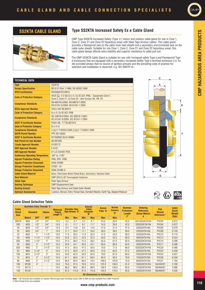
CMPHA
ZARD
OUSAR
EAPR
ODUC
TS
CMPC A B L E G L A N D A N D C A B L E C O N N E C T I O N S P E C I A L I S T S
118www.cmp-products.com
CMP Type SS2KTA Increased Safety (Type 'e') indoor and outdoor cable gland for use in Zone 1,Zone 2, Zone 21 and Zone 22 hazardous areas with Steel Tape Armour cables. This cable glandprovides a flameproof seal on the cable inner lead sheath and a secondary environmental seal on thecable outer sheath. Suitable for use Zone 1, Zone 2, Zone 21 and Zone 22 hazardous areas, thiscable gland design affords extra stability and superior resistance to cable pull out.
The CMP SS2KTA Cable Gland is suitable for use with Increased safety Type e and Flameproof Typed enclosures that are equipped with a secondary Increased Safety Type e terminal enclosure (i.e. Exde) provided always that no source of ignition prevails and the prevailing code of practice forselection and installation is observed, e.g. IEC 60079-14.
Type SS2KTA Increased Safety Ex e Cable GlandSS2KTA CABLE GLAND
AA
CC
EE
BB
DD
FF
Cable Gland Selection Table
Note: *LSF Shrouds also available on request. Marine approvals including Lloyds, DNV & ABS are also available from CMP Products.# Other thread forms are available.
TECHNICAL DATA
Type SS2KTADesign Specification BS 6121:Part 1:1989, EN 50262:1999ATEX Certification SIRA06ATEX1097X
Code of Protection Category ATEX II 2 GD Ex e II, Ex tD A21 IP66, - Equipment Zone 1,Zone 2, Zone 21, & Zone 22 - Gas Groups IIA, IIB, IIC
Compliance Standards EN 60079-0:2004, EN 60079-7:2003,EN 61241-0:2004, EN 61241-1:2004
IECEx Approval Number IECEx SIR 06.0041X
Code of Protection Category Ex e II, Ex tD A21 IP66
Compliance Standards IEC 60079-0:2004, IEC 60079-7:2001,IEC 61241-0:2004, IEC 61241-1:2004
GOST R Certificate Number POCC GB. 05.B01912Code of Protection Category Ex e II UCompliance Standards P 52350.0-2005, P 52350.7-2005
GGTN Permit Number PPC 00-18262GOST K Certificate Number KZ7500052.05.01.00063RoK Permit for Use Number 08-067693Lloyds Approval Number 01/00172DNV Approval Number E-6157ABS Approval Number 01-LD 234401-PDAContinuous Operating Temperature -60° to +130°Ingress Protection Rating IP66, IP67, IP68Ingress Protection Document 5046 C549KDeluge Protection Compliance DTS01 : 91Deluge Protection Document 5046 C549K-DCable Gland Material Brass, Electroless Nickel Plated Brass, Aluminium, Stainless Steel
Seal Material CMP SOLO LSF Thermoplastic ElastomerCable Type Steel Tape ArmourSealing Technique CMP Displacement SealSealing Area(s) Steel Tape Armour and Cable Outer SheathOptional Accessories Locknut, Shroud, Entry Thread Seal, Serrated Washer, Earth Tag, Adaptor/Reducer
LLU
CableGlandSize
Available Entry Threads ‘C’MinimumThread
Length ‘E’
Diameter OverTape Armour ‘A’
OverallCable
Diameter‘B’
AcrossFlats ‘D’
AcrossCorners
‘D’
NominalProtrusionLength‘F’
OrderingReference
(Brass Metric)#
PVCShroud
Reference*
CableGlandWeight(Kgs)
Standard Option
Metric NPT NPT Min Max Min Max Max Max20S/16 M20 1/2” 3/4” 15.0 3.2 8.7 3.2 8.7 24.0 26.6 42.0 20S16SS2KTA1RA PVC04 0.07220S M20 1/2” 3/4” 15.0 6.1 11.7 6.1 11.7 24.0 26.6 42.0 20SSS2KTA1RA PVC04 0.07220 M20 1/2” 3/4” 15.0 6.5 14.0 6.5 14.0 27.0 31.0 47.0 20SS2KTA1RA PVC05 0.07925 M25 3/4” 1” 15.0 11.1 20.0 11.1 20.0 36.0 39.0 56.0 25SS2KTA1RA PVC09 0.14932 M32 1” 1-1/4” 15.0 17.0 26.3 17.0 26.3 41.0 45.0 58.0 32SS2KTA1RA PVC10 0.17040 M40 1-1/4” 1-1/2” 15.0 23.5 32.2 23.5 32.2 50.0 53.5 60.0 40SS2KTA1RA PVC13 0.22450S M50 1-1/2” 2” 15.0 31.0 38.2 31.0 38.2 55.0 61.0 62.0 50SSS2KTA1RA PVC14 0.29850 M50 2” 2-1/2” 15.0 35.6 44.1 35.6 44.1 60.0 66.0 64.0 50SS2KTA1RA PVC17 0.30863S M63 2” 2-1/2” 15.0 41.5 50.0 41.5 50.0 70.0 77.5 66.0 63SSS2KTA1RA PVC20 0.48063 M63 2-1/2” 3” 15.0 47.2 56.0 47.2 56.0 75.0 84.0 67.0 63SS2KTA1RA PVC22 0.45875S M75 2-1/2” 3” 15.0 54.0 62.0 54.0 62.0 79.0 87.0 68.0 75SSS2KTA1RA PVC24 0.62175 M75 3” 3-1/2” 15.0 61.1 68.0 61.1 68.0 84.0 94.0 70.0 75SS2KTA1RA PVC26 0.52690 M90 3” 3-1/2” 15.0 66.6 80.0 66.6 79.4 108.0 120.0 75.0 90SS2KTA1RA PVC31 1.795100 M100 4” - 15.0 76.0 91.0 76.0 91.0 122.0 138.0 81.0 100SS2KTA1RA 150/50HST 2.100115 M115 - - 15.0 86.0 98.0 86.0 98.0 138.0 148.0 85.0 115SS2KTA1RA 180/60HST 3.096130 M130 - - 15.0 97.0 115.0 97.0 115.0 154.0 178.0 92.0 130SS2KTA1RA 180/60HST 4.530
All dimensions in millimetres
OCTL
OCTL
LLU05
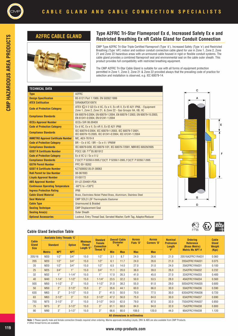
CMPCM
PHA
ZARD
OUSAR
EAPR
ODUC
TSC A B L E G L A N D A N D C A B L E C O N N E C T I O N S P E C I A L I S T S
119 www.cmp-products.com
TECHNICAL DATA
Type A2FRC
Design Specification BS 6121:Part 1:1989, EN 50262:1999
ATEX Cetification SIRA06ATEX1097X
Code of Protection Category ATEX II 2 GD Ex d IIC, Ex e II, Ex nR II, Ex tD A21 IP66, - EquipmentZone 1, Zone 2, Zone 21, & Zone 22 - Gas Groups IIA, IIB, IIC
Compliance Standards EN 60079-0:2004, EN 60079-1:2004, EN 60079-7:2003, EN 60079-15:2003,EN 61241-0:2004, EN 61241-1:2004
IECEx Approval Number IECEx SIR 06.0040X
Code of Protection Category Ex d IIC, Ex e II, Ex nR II, Ex tD A21 IP66
Compliance Standards IEC 60079-0:2004, IEC 60079-1:2003, IEC 60079-7:2001,IEC 60079-15:2005, IEC 61241-0:2004, IEC 61241-1:2004
INMETRO Approval Certificate Number MC, AEX-7619-X
Code of Protection Category BR – Ex d IIC / BR – Ex e II / IP66W
Compliance Standards IEC 60079-0/00, IEC 60079-1/01, IEC 60079-7/2001, NBR/IEC 60529/2005
GOST R Certificate Number POCC GB. 05.B01912
Code of Protection Category Ex d IIC U / Ex e II U
Compliance Standards P 52350.0-2005, P 52350.1-2005, P 52350.7-2005
GGTN Permit Number PPC 00-18262
GOST K Certificate Number KZ7500052.05.01.00063
RoK Permit for Use Number 08-067693
Lloyds Approval Number 01/00172
ABS Approval Number 01-LD 234401-PDA
Continuous Operating Temperature -60°C to +130°C
Ingress Protection Rating IP66
Cable Gland Material Brass, Electroless Nickel Plated Brass, Aluminium, Stainless Steel
Seal Material CMP SOLO LSF Thermoplastic Elastomer
Cable Type Unarmoured & Braided
Sealing Technique CMP Displacement Seal
Sealing Area(s) Outer Sheath
Optional Accessories Locknut, Entry Thread Seal, Serrated Washer, Earth Tag, Adaptor/Reducer
CMP Type A2FRC Tri-Star Triple Certified Flameproof (Type 'd'), Increased Safety (Type 'e') and RestrictedBreathing (Type ‘nR’) indoor and outdoor conduit connection cable gland for use in Zone 1, Zone 2, Zone21 and Zone 22 hazardous areas with un-armoured cable housed in rigid or flexible conduit systems. Thecable gland provides a combined flameproof seal and environmental seal on the cable outer sheath. Thisproduct provides full compatibility with restricted breathing equipment.
The CMP A2FRC Tri-Star Cable Gland is suitable for use with all forms of equipment protectionpermitted in Zone 1, Zone 2, Zone 21 & Zone 22 provided always that the prevailing code of practice forselection and installation is observed, e.g. IEC 60079-14.
CableGlandSize
Available Entry Threads ‘C’MinimumThread
Length ‘E’’
StandardFemale
ConnectionThread ‘G’
Overall CableDiameter
‘A’
AcrossFlats ‘D’
AcrossCorners ‘D’
NominalProtrusionLength‘F’
OrderingReference
(Brass Metric)Metric Mx NPT #
CableGlandWeight(Kgs)
Standard Option
Metric NPT NPT Min Max Max Max
20S/16 M20 1/2” 3/4” 15.0 1/2” 3.1 8.7 24.0 26.6 21.0 20S16A2FRC1RA031 0.060
20S M20 1/2” 3/4” 15.0 1/2” 6.1 11.7 24.0 26.6 21.0 20SA2FRC1RA031 0.075
20 M20 1/2” 3/4” 15.0 1/2” 6.5 14.0 27.0 31.0 24.0 20A2FRC1RA031 0.100
25 M25 3/4” 1” 15.0 3/4” 11.1 20.0 36.0 39.0 26.0 25A2FRC1RA032 0.232
32 M32 1” 1-1/4” 15.0 1” 17.0 26.3 41.0 45.0 27.0 32A2FRC1RA033 0.400
40 M40 1-1/4” 1-1/2” 15.0 1-1/4” 23.5 32.2 50.0 53.5 28.0 40A2FRC1RA034 0.560
50S M50 1-1/2” 2” 15.0 1-1/2” 31.0 38.2 55.0 61.0 29.0 50SA2FRC1RA035 0.600
50 M50 2” 2-1/2” 15.0 2” 35.6 44.1 60.0 66.0 30.0 50A2FRC1RA036 0.590
63S M63 2” 2-1/2” 15.0 2” 41.5 50.0 70.0 77.5 30.0 63SA2FRC1RA036 0.720
63 M63 2-1/2” 3” 15.0 2-1/2” 47.2 56.0 75.0 84.0 30.0 63A2FRC1RA037 0.690
75S M75 2-1/2” 3” 15.0 2-1/2” 54.0 62.0 79.0 87.0 32.0 75SA2FRC1RA037 0.850
75 M75 3” 3-1/2” 15.0 3” 61.1 68.0 84.0 94.0 32.0 75A2FRC1RA038 0.800
90 M90 3” 3-1/2” 15.0 3” 66.6 80.0 108.0 120.0 44.0 90A2FRC1RA038 1.120
All dimensions in millimetres
Type A2FRC Tri-Star Flameproof Ex d, Increased Safety Ex e andRestricted Breathing Ex nR Cable Gland for Conduit ConnectionA2FRC CABLE GLAND
AA
CC
EE
DD
GG
FF
Cable Gland Selection Table
Note: † Please specify male and female connection threads required when ordering. Marine approvals including Lloyds, DNV & ABS are also available from CMP Products.# Other thread forms are available.
LLU
OCTL
OCTL
OCTL
LLU05
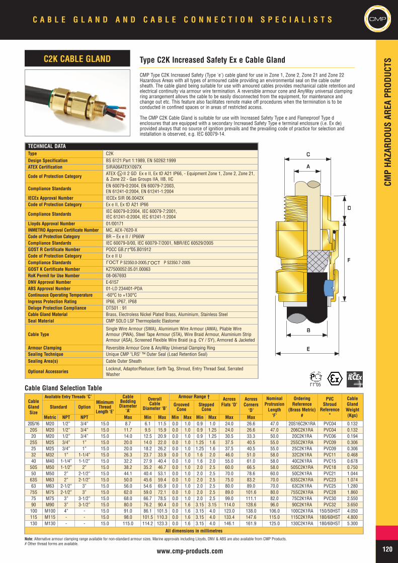
CMPHA
ZARD
OUSAR
EAPR
ODUC
TS
CMPC A B L E G L A N D A N D C A B L E C O N N E C T I O N S P E C I A L I S T S
120www.cmp-products.com
TECHNICAL DATAType C2KDesign Specification BS 6121:Part 1:1989, EN 50262:1999ATEX Certification SIRA06ATEX1097X
Code of Protection Category ATEX II 2 GD Ex e II, Ex tD A21 IP66, - Equipment Zone 1, Zone 2, Zone 21,& Zone 22 - Gas Groups IIA, IIB, IIC
Compliance Standards EN 60079-0:2004, EN 60079-7:2003,EN 61241-0:2004, EN 61241-1:2004
IECEx Approval Number IECEx SIR 06.0042XCode of Protection Category Ex e II, Ex tD A21 IP66
Compliance Standards IEC 60079-0:2004, IEC 60079-7:2001,IEC 61241-0:2004, IEC 61241-1:2004
Lloyds Approval Number 01/00171INMETRO Approval Certificate Number MC, AEX-7620-XCode of Protection Category BR – Ex e II / IP66WCompliance Standards IEC 60079-0/00, IEC 60079-7/2001, NBR/IEC 60529/2005GOST R Certificate Number POCC GB. 05.B01912Code of Protection Category Ex e II UCompliance Standards P 52350.0-2005, P 52350.7-2005GOST K Certificate Number KZ7500052.05.01.00063RoK Permit for Use Number 08-067693DNV Approval Number E-6157ABS Approval Number 01-LD 234401-PDAContinuous Operating Temperature -60°C to +130°CIngress Protection Rating IP66, IP67, IP68Deluge Protection Compliance DTS01 : 91Cable Gland Material Brass, Electroless Nickel Plated Brass, Aluminium, Stainless SteelSeal Material CMP SOLO LSF Thermoplastic Elastomer
Cable TypeSingle Wire Armour (SWA), Aluminium Wire Armour (AWA), Pliable WireArmour (PWA), Steel Tape Armour (STA), Wire Braid Armour, Aluminium StripArmour (ASA), Screened Flexible Wire Braid (e.g. CY / SY), Armored & Jacketed
Armour Clamping Reversible Armour Cone & AnyWay Universal Clamping RingSealing Technique Unique CMP "LRS" ™ Outer Seal (Load Retention Seal)Sealing Area(s) Cable Outer Sheath
Optional Accessories Locknut, Adaptor/Reducer, Earth Tag, Shroud, Entry Thread Seal, SerratedWasher
CMP Type C2K Increased Safety (Type 'e') cable gland for use in Zone 1, Zone 2, Zone 21 and Zone 22Hazardous Areas with all types of armoured cable providing an environmental seal on the cable outersheath. The cable gland being suitable for use with amoured cables provides mechanical cable retention andelectrical continuity via armour wire termination. A reversible armour cone and AnyWay universal clampingring arrangement allows the cable to be easily disconnected from the equipment, for maintenance andchange out etc. This feature also facilitates remote make off procedures when the termination is to beconducted in confined spaces or in areas of restricted access.
The CMP C2K Cable Gland is suitable for use with Increased Safety Type e and Flameproof Type denclosures that are equipped with a secondary Increased Safety Type e terminal enclosure (i.e. Ex de)provided always that no source of ignition prevails and the prevailing code of practice for selection andinstallation is observed, e.g. IEC 60079-14.
CableGlandSize
Available Entry Threads ‘C’MinimumThread
Length ‘E’
CableBeddingDiameter
‘A’
OverallCable
Diameter ‘B’
Armour Range † AcrossFlats ‘D’
AcrossCorners
‘D’
NominalProtrusionLength‘F’
OrderingReference
(Brass Metric)#
PVCShroud
Reference*
CableGlandWeight(Kgs)
Standard Option GroovedCone
SteppedCone
Metric NPT NPT Max Min Max Min Max Min Max Max Max20S/16 M20 1/2” 3/4” 15.0 8.7 6.1 11.5 0.0 1.0 0.9 1.0 24.0 26.6 47.0 20S16C2K1RA PVC04 0.13220S M20 1/2” 3/4” 15.0 11.7 9.5 15.9 0.0 1.0 0.9 1.25 24.0 26.6 47.0 206C2K1RA PVC04 0.13220 M20 1/2” 3/4” 15.0 14.0 12.5 20.9 0.0 1.0 0.9 1.25 30.5 33.3 50.0 20C2K1RA PVC06 0.19425S M25 3/4” 1” 15.0 20.0 14.0 22.0 0.0 1.0 1.25 1.6 37.5 40.5 55.0 25SC2K1RA PVC09 0.30625 M25 3/4” 1” 15.0 20.0 18.2 26.2 0.0 1.0 1.25 1.6 37.5 40.5 55.0 25C2K1RA PVC09 0.30632 M32 1” 1-1/4” 15.0 26.3 23.7 33.9 0.0 1.0 1.6 2.0 46.0 51.0 58.0 32C2K1RA PVC11 0.46840 M40 1-1/4” 1-1/2” 15.0 32.2 27.9 40.4 0.0 1.0 1.6 2.0 55.0 61.0 58.0 40C2K1RA PVC15 0.67850S M50 1-1/2” 2” 15.0 38.2 35.2 46.7 0.0 1.0 2.0 2.5 60.0 66.5 58.0 50SC2K1RA PVC18 0.75050 M50 2” 2-1/2” 15.0 44.1 40.4 53.1 0.0 1.0 2.0 2.5 70.0 78.6 60.0 50C2K1RA PVC21 1.04463S M63 2” 2-1/2” 15.0 50.0 45.6 59.4 0.0 1.0 2.0 2.5 75.0 83.2 70.0 63SC2K1RA PVC23 1.07463 M63 2-1/2” 3” 15.0 56.0 54.6 65.9 0.0 1.0 2.0 2.5 80.0 89.0 70.0 63C2K1RA PVC25 1.28075S M75 2-1/2” 3” 15.0 62.0 59.0 72.1 0.0 1.0 2.0 2.5 89.0 101.6 80.0 75SC2K1RA PVC28 1.86075 M75 3” 3-1/2” 15.0 68.0 66.7 78.5 0.0 1.0 2.0 2.5 99.0 111.1 82.0 75C2K1RA PVC30 2.55090 M90 3” 3-1/2” 15.0 80.0 76.2 90.4 0.0 1.6 3.15 3.15 114.0 128.6 96.0 90C2K1RA PVC32 3.650100 M100 4” - 15.0 91.0 86.1 101.5 0.0 1.6 3.15 4.0 123.0 138.0 106.0 100C2K1RA 150/50HST 4.050115 M115 - - 15.0 98.0 101.5 110.3 0.0 1.6 3.15 4.0 133.4 147.6 115.0 115C2K1RA 180/60HST 4.800130 M130 - - 15.0 115.0 114.2 123.3 0.0 1.6 3.15 4.0 146.1 161.9 125.0 130C2K1RA 180/60HST 5.300
All dimensions in millimetres
Type C2K Increased Safety Ex e Cable GlandC2K CABLE GLAND
AA
BB
EE
CC
DD
FF
Cable Gland Selection Table
Note: Alternative armour clamping range available for non-standard armour sizes. Marine approvals including Lloyds, DNV & ABS are also available from CMP Products.# Other thread forms are available.
LLU
LLU05
OCTL
OCTL
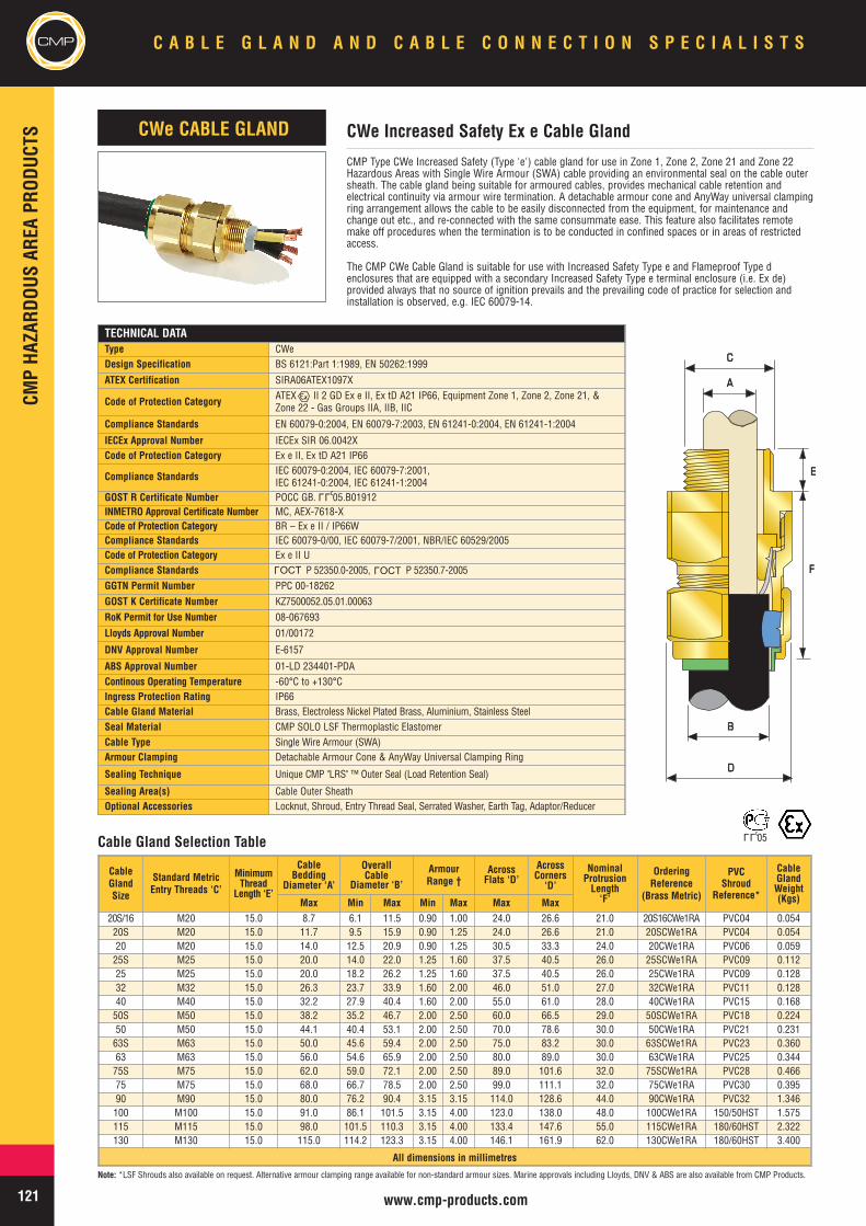
CMPCM
PHA
ZARD
OUSAR
EAPR
ODUC
TSC A B L E G L A N D A N D C A B L E C O N N E C T I O N S P E C I A L I S T S
121 www.cmp-products.com
Note: *LSF Shrouds also available on request. Alternative armour clamping range available for non-standard armour sizes. Marine approvals including Lloyds, DNV & ABS are also available from CMP Products.
Cable Gland Selection Table
CMP Type CWe Increased Safety (Type 'e') cable gland for use in Zone 1, Zone 2, Zone 21 and Zone 22Hazardous Areas with Single Wire Armour (SWA) cable providing an environmental seal on the cable outersheath. The cable gland being suitable for armoured cables, provides mechanical cable retention andelectrical continuity via armour wire termination. A detachable armour cone and AnyWay universal clampingring arrangement allows the cable to be easily disconnected from the equipment, for maintenance andchange out etc., and re-connected with the same consummate ease. This feature also facilitates remotemake off procedures when the termination is to be conducted in confined spaces or in areas of restrictedaccess.
The CMP CWe Cable Gland is suitable for use with Increased Safety Type e and Flameproof Type denclosures that are equipped with a secondary Increased Safety Type e terminal enclosure (i.e. Ex de)provided always that no source of ignition prevails and the prevailing code of practice for selection andinstallation is observed, e.g. IEC 60079-14.
TECHNICAL DATAType CWeDesign Specification BS 6121:Part 1:1989, EN 50262:1999
ATEX Certification SIRA06ATEX1097X
Code of Protection Category ATEX II 2 GD Ex e II, Ex tD A21 IP66, Equipment Zone 1, Zone 2, Zone 21, &Zone 22 - Gas Groups IIA, IIB, IIC
Compliance Standards EN 60079-0:2004, EN 60079-7:2003, EN 61241-0:2004, EN 61241-1:2004
IECEx Approval Number IECEx SIR 06.0042XCode of Protection Category Ex e II, Ex tD A21 IP66
Compliance Standards IEC 60079-0:2004, IEC 60079-7:2001,IEC 61241-0:2004, IEC 61241-1:2004
GOST R Certificate Number POCC GB. 05.B01912INMETRO Approval Certificate Number MC, AEX-7618-XCode of Protection Category BR – Ex e II / IP66WCompliance Standards IEC 60079-0/00, IEC 60079-7/2001, NBR/IEC 60529/2005Code of Protection Category Ex e II UCompliance Standards P 52350.0-2005, P 52350.7-2005GGTN Permit Number PPC 00-18262GOST K Certificate Number KZ7500052.05.01.00063RoK Permit for Use Number 08-067693
Lloyds Approval Number 01/00172
DNV Approval Number E-6157
ABS Approval Number 01-LD 234401-PDAContinous Operating Temperature -60°C to +130°CIngress Protection Rating IP66Cable Gland Material Brass, Electroless Nickel Plated Brass, Aluminium, Stainless SteelSeal Material CMP SOLO LSF Thermoplastic ElastomerCable Type Single Wire Armour (SWA)Armour Clamping Detachable Armour Cone & AnyWay Universal Clamping Ring
Sealing Technique Unique CMP "LRS" ™ Outer Seal (Load Retention Seal)
Sealing Area(s) Cable Outer SheathOptional Accessories Locknut, Shroud, Entry Thread Seal, Serrated Washer, Earth Tag, Adaptor/Reducer
CWe Increased Safety Ex e Cable GlandCWe CABLE GLAND
CableGlandSize
Standard MetricEntry Threads ‘C’
MinimumThread
Length ‘E’
CableBedding
Diameter ‘A’
OverallCable
Diameter ‘B’
ArmourRange †
AcrossFlats ‘D’
AcrossCorners
‘D’
NominalProtrusionLength‘F’
OrderingReference
(Brass Metric)
PVCShroud
Reference*
CableGlandWeight(Kgs)Max Min Max Min Max Max Max
20S/16 M20 15.0 8.7 6.1 11.5 0.90 1.00 24.0 26.6 21.0 20S16CWe1RA PVC04 0.05420S M20 15.0 11.7 9.5 15.9 0.90 1.25 24.0 26.6 21.0 20SCWe1RA PVC04 0.05420 M20 15.0 14.0 12.5 20.9 0.90 1.25 30.5 33.3 24.0 20CWe1RA PVC06 0.05925S M25 15.0 20.0 14.0 22.0 1.25 1.60 37.5 40.5 26.0 25SCWe1RA PVC09 0.11225 M25 15.0 20.0 18.2 26.2 1.25 1.60 37.5 40.5 26.0 25CWe1RA PVC09 0.12832 M32 15.0 26.3 23.7 33.9 1.60 2.00 46.0 51.0 27.0 32CWe1RA PVC11 0.12840 M40 15.0 32.2 27.9 40.4 1.60 2.00 55.0 61.0 28.0 40CWe1RA PVC15 0.16850S M50 15.0 38.2 35.2 46.7 2.00 2.50 60.0 66.5 29.0 50SCWe1RA PVC18 0.22450 M50 15.0 44.1 40.4 53.1 2.00 2.50 70.0 78.6 30.0 50CWe1RA PVC21 0.23163S M63 15.0 50.0 45.6 59.4 2.00 2.50 75.0 83.2 30.0 63SCWe1RA PVC23 0.36063 M63 15.0 56.0 54.6 65.9 2.00 2.50 80.0 89.0 30.0 63CWe1RA PVC25 0.34475S M75 15.0 62.0 59.0 72.1 2.00 2.50 89.0 101.6 32.0 75SCWe1RA PVC28 0.46675 M75 15.0 68.0 66.7 78.5 2.00 2.50 99.0 111.1 32.0 75CWe1RA PVC30 0.39590 M90 15.0 80.0 76.2 90.4 3.15 3.15 114.0 128.6 44.0 90CWe1RA PVC32 1.346100 M100 15.0 91.0 86.1 101.5 3.15 4.00 123.0 138.0 48.0 100CWe1RA 150/50HST 1.575115 M115 15.0 98.0 101.5 110.3 3.15 4.00 133.4 147.6 55.0 115CWe1RA 180/60HST 2.322130 M130 15.0 115.0 114.2 123.3 3.15 4.00 146.1 161.9 62.0 130CWe1RA 180/60HST 3.400
All dimensions in millimetres
AA
BB
DD
CC
EE
FFOCTL
OCTL
LLU
LLU05

CMPHA
ZARD
OUSAR
EAPR
ODUC
TS
CMPC A B L E G L A N D A N D C A B L E C O N N E C T I O N S P E C I A L I S T S
122www.cmp-products.com
Cable Gland Selection Table
Note: †Alternative armour clamping range available for non-standard armour sizes. Marine approvals including Lloyds, DNV & ABS are also available from CMP Products.
CMP Type CXe Increased Safety (Type 'e') cable gland for use in Zone 1, Zone 2, Zone 21 and Zone 22Hazardous Areas with Braided, Pliable Wire Armour (PWA), Strip Armour and Steel Tape Armour (STA)cable providing an environmental seal on the cable outer sheath. The cable gland being suitable forarmoured cables, provides mechanical cable retention and electrical continuity via armour wire termination.A detachable armour cone and AnyWay universal clamping ring arrangement allows the cable to be easilydisconnected from the equipment, for maintenance and change out etc., and re-connected with the sameconsummate ease. This feature also facilitates remote make off procedures when the termination is to beconducted in confined spaces or in areas of restricted access.
The CMP CXe Cable Gland is suitable for use with Increased Safety Type e and Flameproof Type denclosures that are equipped with a secondary Increased Safety Type e terminal enclosure (i.e. Ex de)provided always that no source of ignition prevails and the prevailing code of practice for selection andinstallation is observed, e.g. IEC 60079-14.
TECHNICAL DATAType CXe
Design Specification BS 6121:Part 1:1989, EN 50262:1999ATEX Certification SIRA06ATEX1097X
Code of Protection Category ATEX II 2 GD Ex e II, Ex tD A21 IP66, Equipment Zone 1, Zone 2, Zone 21,& Zone 22 - Gas Groups IIA, IIB, IIC
Compliance Standards EN 60079-0:2004, EN 60079-7:2003, EN 61241-0:2004, EN 61241-1:2004IECEx Approval Number IECEx SIR 06.0042XCode of Protection Category Ex e II / Ex tD A21 IP66
Compliance Standards IEC 60079-0:2004, IEC 60079-7:2001,IEC 61241-0:2004, IEC 61241-1:2004
GOST R Certificate Number POCC GB. 05.B01912INMETRO Approval Certificate Number MC, AEX-7618-XCode of Protection Category BR – Ex e II / IP66WCompliance Standards IEC 60079-0/00, IEC 60079-7/2001, NBR/IEC 60529/2005Code of Protection Category Ex e II UCompliance Standards P 52350.0-2005, P 52350.7-2005GGTN Permit Number PPC 00-18262GOST K Certificate Number KZ7500052.05.01.00063RoK Permit for Use Number 08-067693Lloyds Approval Number 01/00172DNV Approval Number E-6157ABS Approval Number 01-LD 234401-PDAContinuous Operating Temperature -60°C to +130°CIngress Protection Rating IP66Cable Gland Material Brass, Electroless Nickel Plated Brass, Aluminium, Stainless SteelSeal Material CMP SOLO LSF Thermoplastic Elastomer
Cable Type Wire Braid Armour, Screened Flexible Wire Braid (e.g. CY / SY), Strip Armour,Pliable Wire Armour (PWA), Steel Tape Armour (STA)
Armour Clamping Detachable Armour Cone & AnyWay Universal Clamping RingSealing Technique Unique CMP "LRS" ™ Outer Seal (Load Retention Seal)Sealing Area(s) Cable Outer Sheath
Optional Accessories Locknut, Shroud, Entry Thread Seal, Serrated Washer, Earth Tag,Adaptor/Reducer
CableGlandSize
StandardMetric EntryThreads ‘C’
MinimumThread
Length ‘E’
CableBeddingDiameter
‘A’
OverallCable
Diameter ‘B’Armour Range †
AcrossFlats ‘D’
AcrossCorners
‘D’
NominalProtrusionLength ‘F’
OrderingReference
(Brass Metric)
PVCShroud
Reference*
CableGlandWeightKgsMin Max Min Max Max Max
20S/16 M20 15.0 8.7 6.1 11.5 0.15 1.0 24.0 26.6 21.0 20S16CXe1RA PVC04 0.05420S M20 15.0 11.7 9.5 15.9 0.15 1.0 24.0 26.6 21.0 20SCXe1RA PVC04 0.05420 M20 15.0 14.0 12.5 20.9 0.15 1.0 30.5 33.3 24.0 20CXe1RA PVC06 0.05925S M25 15.0 20.0 14.0 22.0 0.15 1.0 37.5 40.5 26.0 25SCXe1RA PVC09 0.11225 M25 15.0 20.0 18.2 26.2 0.15 1.0 37.5 40.5 26.0 25CXe1RA PVC09 0.12832 M32 15.0 26.3 23.7 33.9 0.15 1.0 46.0 51.0 27.0 32CXe1RA PVC11 0.12840 M40 15.0 32.2 27.9 40.4 0.15 1.0 55.0 61.0 28.0 40CXe1RA PVC15 0.16850S M50 15.0 38.2 35.2 46.7 0.15 1.0 60.0 66.5 29.0 50SCXe1RA PVC18 0.22450 M50 15.0 44.1 40.4 53.1 0.15 1.0 70.0 78.6 30.0 50CXe1RA PVC21 0.23163S M63 15.0 50.0 45.6 59.4 0.15 1.0 75.0 83.2 30.0 63SCXe1RA PVC23 0.36063 M63 15.0 56.0 54.6 65.9 0.15 1.0 80.0 89.0 30.0 63CXe1RA PVC25 0.34475S M75 15.0 62.0 59.0 72.1 0.15 1.0 89.0 101.6 32.0 75SCXe1RA PVC28 0.46675 M75 15.0 68.0 66.7 78.5 0.15 1.0 99.0 111.1 32.0 75CXe1RA PVC30 0.39590 M90 15.0 80.0 76.2 90.4 0.25 1.6 114.0 128.6 44.0 90CXe1RA PVC32 1.346100 M100 15.0 91.0 86.1 101.5 0.25 1.6 123.0 138.0 48.0 100CXe1RA 150/50HST 1.575115 M115 15.0 98.0 101.5 110.3 0.25 1.6 133.4 147.6 55.0 115CXe1RA 180/60HST 2.322130 M130 15.0 115.0 114.2 123.3 0.25 1.6 146.1 161.9 62.0 130CXe1RA 180/60HST 3.400
All dimensions in millimetres
CXe Increased Safety Ex e Cable GlandCXe CABLE GLAND
AA
BB
DD
CC
EE
FF
LLU
LLU05
OCTL
OCTL
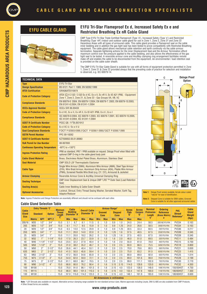
CMPCM
PHA
ZARD
OUSAR
EAPR
ODUC
TSC A B L E G L A N D A N D C A B L E C O N N E C T I O N S P E C I A L I S T S
123 www.cmp-products.com
CMP Type E1FU Tri-Star Triple Certified Flameproof (Type ‘d’), Increased Safety (Type ‘e’) and RestrictedBreathing (Type ‘nR’) indoor and outdoor cable gland for use in Zone 1, Zone 2, Zone 21 and Zone 22Hazardous Areas with all types of armoured cable. This cable gland provides a Flameproof seal on the cableinner bedding and in addition the gas tight seal has been tested to prove compatibility with Restricted Breathingequipment. The cable gland allows mechanical cable retention and earth continuity via the cable armourtermination. Separate tightening actions for the inner Displacement Seal and the Armour Termination affordmaximum control over the pressure applied to the cable bedding, and also allows the effectiveness of the gastight seal to be tested. A reversible armour cone and AnyWay clamping ring arrangement facilitates remotemake off and enables the cable to be disconnected from the equipment. An environmental / load retention sealis provided on the cable outer sheath.
The CMP E1FU Tri-Star Cable Gland is suitable for use with all forms of equipment protection permitted in Zone1, Zone 2, Zone 21 & Zone 22 provided always that the prevailing code of practice for selection and installationis observed, e.g. IEC 60079-14.
TECHNICAL DATAType E1FU Tri-StarDesign Specification BS 6121: Part 1: 1989, EN 50262:1999ATEX Certification SIRA06ATEX1097X
Code of Protection Category ATEX II 2 GD / 3 GD Ex d IIC, Ex e II, Ex nR II, Ex tD A21 IP66, - EquipmentZone 1, Zone 2, Zone 21, & Zone 22 - Gas Groups IIA, IIB, IIC
Compliance Standards EN 60079-0: 2004, EN 60079-1:2004, EN 60079-7: 2003, EN 60079-15:2003,EN 61241-0:2004, EN 61241-1:2004
IECEx Approval Number IECEx SIR 06.0043X
Code of Protection Category Ex d IIC, Ex e II, Ex nR II, Ex tD A21 IP66, Ex d I, Ex e I
Compliance Standards IEC 60079-0:2004, IEC 60079-1:2003, IEC 60079-7:2001, IEC 60079-15:2005,IEC 61241-0:2004, IEC 61241-1:2004
GOST R Certificate Number POCC GB. 05.BO1912
Code of Protection Category Ex d IIC U / Ex e II U
Gost Compliance Standards P 52350.0-2005, P 52350.1-2005, P 52350.7-2005
GGTN Permit Number PPC 00-18262
GOST K Certificate Number KZ7500052.05.01.00063
RoK Permit for Use Number 08-067693
Continuous Operating Temperature -60°C to +130°C
Ingress Protection Rating IP66 as standard, IP67 / IP68 available on request. Deluge Proof when fitted withoptional CMP O-ring in the cable gland body joint
Cable Gland Material Brass, Electroless Nickel Plated Brass, Aluminium, Stainless Steel
Seal Material CMP SOLO LSF Thermoplastic Elastomer
Cable TypeSingle Wire Armour (SWA), Aluminium Wire Armour (AWA), Steel Tape Armour(STA), Wire Braid Armour, Aluminium Strip Armour (ASA), Pliable Wire Armour(PWA), Screened Flexible Wire Braid (e.g. CY / SY), Armoured & Jacketed
Armour Clamping Reversible Armour Cone & AnyWay Universal Clamping Ring
Sealing Technique CMP Inner Displacement Seal & Unique CMP "LRS" ™ Outer Seal (Load RetentionSeal)
Sealing Area(s) Cable Inner Bedding & Cable Outer Sheath
Optional Accessories Locknut, Shroud, Entry Thread Seaing Washer, Serrated Washer, Earth Tag,Adaptor/Reducer
CableGlandSize
Entry Threads ‘C’MinimumThreadLength‘E’
CableBedding
Diameter ‘A’
Overall CableDiameter ‘B’
Armour Range†
AcrossFlats‘D’
AcrossCorners
‘D’
NominalProtrusionLength‘F’
OrderingReference
(Brass Metric)#
PVCShroud
Reference*
CableGlandWeight(Kgs)
Standard Option GroovedCone
SteppedCone
Metric NPT NPT 2 Min Max Min Max Min Max Min Max Max Max20S/16 M20 1/2” 3/4” 15.0 3.1 8.7 6.1 11.5 0 1.0 0.9 1.0 24.0 24.4 58.5 20S16E1FU1RA PVC04 0.16320S M20 1/2” 3/4” 15.0 6.1 11.7 9.5 15.9 0 1.0 0.9 1.25 24.0 26.6 58.5 20SE1FU1RA PVC04 0.16320 M20 1/2” 3/4” 15.0 6.5 14.0 12.5 20.9 0 1.0 0.9 1.25 30.5 33.3 60.5 20E1FU1RA PVC06 0.21725S M25 3/4” 1” 15.0 11.1 20.0 14.0 22.0 0 1.0 1.25 1.6 37.5 40.5 67.5 25SE1FU1RA PVC09 0.34525 M25 3/4” 1” 15.0 11.1 20.0 18.2 26.2 0 1.0 1.25 1.6 37.5 40.5 67.5 25E1FU1RA PVC09 0.34532 M32 1” 1-1/4” 15.0 17.0 26.3 23.7 33.9 0 1.0 1.6 2.0 46.0 51.0 69.5 32E1FU1RA PVC11 0.48440 M40 1-1/4” 1-1/2” 15.0 23.5 32.2 27.9 40.4 0 1.0 1.6 2.0 55.0 61.0 78.0 40E1FU1RA PVC15 0.70050S M50 1-1/2” 2” 15.0 31.0 38.2 35.2 46.7 0 1.0 2.0 2.5 60.0 66.5 75.5 50SE1FU1RA PVC18 0.80050 M50 2” 2-1/2” 15.0 35.6 44.1 40.4 53.1 0 1.0 2.0 2.5 70.0 78.6 80.5 50E1FU1RA PVC21 0.83063S M63 2” 2-1/2” 15.0 41.5 50.0 45.6 59.4 0 1.0 2.0 2.5 75.0 83.2 91.5 63SE1FU1RA PVC23 1.41563 M63 2-1/2” 3” 15.0 47.2 56.0 54.6 65.9 0 1.0 2.0 2.5 80.0 89.0 92.0 63E1FU1RA PVC25 1.51475S M75 2-1/2” 3” 15.0 54.0 62.0 59.0 72.1 0 1.0 2.0 2.5 89.0 101.6 99.0 75SE1FU1RA PVC28 2.19975 M75 3” 3-1/2” 15.0 61.1 68.0 66.7 78.5 0 1.0 2.0 2.5 99.0 111.1 102.0 75E1FU1RA PVC30 2.77090 M90 3-1/2” 4” 15.0 66.6 80.0 76.2 90.4 0 1.6 3.15 3.15 114.0 128.6 120.0 90E1FU1RA PVC32 4.350100 M100 - - 15.0 76.0 91.0 86.1 101.5 0 1.6 3.15 4.0 123.0 138.0 148.0 100E1FU1RA 150/50HST 4.750115 M115 - - 15.0 86.0 98.0 101.5 110.3 0 1.6 3.15 4.0 133.4 147.8 169.0 115E1FU1RA 180/60HST 7.300130 M130 - - 15.0 97.0 115.0 114.2 123.3 0 1.6 3.15 4.0 146.1 161.9 183.0 130E1FU1RA 180/60HST 8.600
All dimensions in millimetres
E1FU Tri-Star Flameproof Ex d, Increased Safety Ex e andRestricted Breathing Ex nR Cable Gland
AA
BB
DD
CC
EE
FF
E1FU CABLE GLAND
Deluge ProofOption
Cable Gland Selection Table
Note: *LSF Shrouds also available on request. Alternative armour clamping range available for non-standard armour sizes. Marine approvals including Lloyds, DNV & ABS are also available from CMP Products.# Other thread forms are available.
LLU
OCTL
OCTL
OCTL
LLU05
Note 1: Deluge Proof version available, ferrule colour coded“natural” for ease of identification.
Note 2: Stepped Cone is suitable for SWA cables, GroovedCone is suitable for all other approved armoured cables
Note: Ingress Protection and Deluge Protection are essentially different and should not be confused with each other.
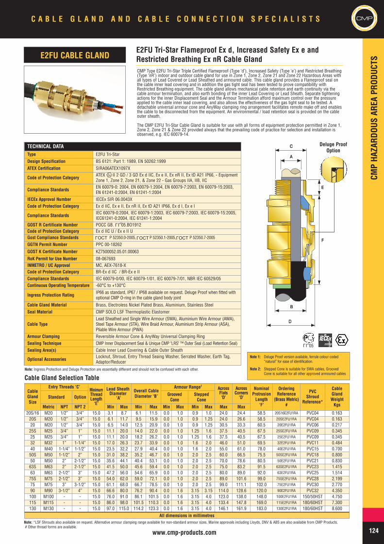
CMPHA
ZARD
OUSAR
EAPR
ODUC
TS
124www.cmp-products.com
C A B L E G L A N D A N D C A B L E C O N N E C T I O N S P E C I A L I S T S
CMP Type E2FU Tri-Star Triple Certified Flameproof (Type ‘d’), Increased Safety (Type ‘e’) and Restricted Breathing(Type ‘nR’) indoor and outdoor cable gland for use in Zone 1, Zone 2, Zone 21 and Zone 22 Hazardous Areas withall types of Lead Covered or Lead Sheathed and armoured cable. This cable gland provides a Flameproof seal onthe cable inner lead covering and in addition the gas tight seal has been tested to prove compatibility withRestricted Breathing equipment. The cable gland allows mechanical cable retention and earth continuity via thecable armour termination, and also earth bonding of the inner Lead Covering or Lead Sheath. Separate tighteningactions for the inner Displacement Seal and the Armour Termination afford maximum control over the pressureapplied to the cable inner lead covering, and also allows the effectiveness of the gas tight seal to be tested. Adetachable universal armour cone and AnyWay clamping ring arrangement facilitates remote make off and enablesthe cable to be disconnected from the equipment. An environmental / load retention seal is provided on the cableouter sheath.
The CMP E2FU Tri-Star Cable Gland is suitable for use with all forms of equipment protection permitted in Zone 1,Zone 2, Zone 21 & Zone 22 provided always that the prevailing code of practice for selection and installation isobserved, e.g. IEC 60079-14.
TECHNICAL DATAType E2FU Tri-StarDesign Specification BS 6121: Part 1: 1989, EN 50262:1999ATEX Certification SIRA06ATEX1097X
Code of Protection Category ATEX II 2 GD / 3 GD Ex d IIC, Ex e II, Ex nR II, Ex tD A21 IP66, - EquipmentZone 1, Zone 2, Zone 21, & Zone 22 - Gas Groups IIA, IIB, IIC
Compliance Standards EN 60079-0: 2004, EN 60079-1:2004, EN 60079-7:2003, EN 60079-15:2003,EN 61241-0:2004, EN 61241-1:2004
IECEx Approval Number IECEx SIR 06.0043XCode of Protection Category Ex d IIC, Ex e II, Ex nR II, Ex tD A21 IP66, Ex d I, Ex e I
Compliance Standards IEC 60079-0:2004, IEC 60079-1:2003, IEC 60079-7:2003, IEC 60079-15:2005,IEC61241-0:2004, IEC 61241-1:2004
GOST R Certificate Number POCC GB. 05.BO1912Code of Protection Category Ex d IIC U / Ex e II UGost Compliance Standards P 52350.0-2005, P 52350.1-2005, P 52350.7-2005
GGTN Permit Number PPC 00-18262
GOST K Certificate Number KZ7500052.05.01.00063
RoK Permit for Use Number 08-067693INMETRO / UC Approval MC, AEX-7618-XCode of Protection Category BR-Ex d IIC / BR-Ex e IICompliance Standards IEC 60079-0/00, IEC 60079-1/01, IEC 60079-7/01, NBR IEC 60529/05Continuous Operating Temperature -60°C to +130°C
Ingress Protection Rating IP66 as standard, IP67 / IP68 available on request. Deluge Proof when fitted withoptional CMP O-ring in the cable gland body joint
Cable Gland Material Brass, Electroless Nickel Plated Brass, Aluminium, Stainless SteelSeal Material CMP SOLO LSF Thermoplastic Elastomer
Cable TypeLead Sheathed and Single Wire Armour (SWA), Aluminium Wire Armour (AWA),Steel Tape Armour (STA), Wire Braid Armour, Aluminium Strip Armour (ASA),Pliable Wire Armour (PWA)
Armour Clamping Reversible Armour Cone & AnyWay Universal Clamping RingSealing Technique CMP Inner Displacement Seal & Unique CMP "LRS" ™ Outer Seal (Load Retention Seal)Sealing Area(s) Cable Inner Lead Covering & Cable Outer Sheath
Optional Accessories Locknut, Shroud, Entry Thread Seaing Washer, Serrated Washer, Earth Tag,Adaptor/Reducer
CableGlandSize
Entry Threads ‘C’MinimumThreadLength‘E’
Lead SheathDiameter
‘A’
Overall CableDiameter ‘B’
Armour Range†AcrossFlats‘D’
AcrossCorners
‘D’
NominalProtrusionLength‘F’
OrderingReference
(Brass Metric)#
PVCShroud
Reference*
CableGlandWeightKgs
Standard Option GroovedCone
SteppedCone
Metric NPT NPT 2 Min Max Min Max Min Max Min Max Max Max20S/16 M20 1/2” 3/4” 15.0 3.1 8.7 6.1 11.5 0.0 1.0 0.9 1.0 24.0 24.4 58.5 20S16E2FU1RA PVC04 0.16320S M20 1/2” 3/4” 15.0 6.1 11.7 9.5 15.9 0.0 1.0 0.9 1.25 24.0 26.6 58.5 20SE2FU1RA PVC04 0.16320 M20 1/2” 3/4” 15.0 6.5 14.0 12.5 20.9 0.0 1.0 0.9 1.25 30.5 33.3 60.5 20E2FU1RA PVC06 0.21725S M25 3/4” 1” 15.0 11.1 20.0 14.0 22.0 0.0 1.0 1.25 1.6 37.5 40.5 67.5 25SE2FU1RA PVC09 0.34525 M25 3/4” 1” 15.0 11.1 20.0 18.2 26.2 0.0 1.0 1.25 1.6 37.5 40.5 67.5 25E2FU1RA PVC09 0.34532 M32 1” 1-1/4” 15.0 17.0 26.3 23.7 33.9 0.0 1.0 1.6 2.0 46.0 51.0 69.5 32E2FU1RA PVC11 0.48440 M40 1-1/4” 1-1/2” 15.0 23.5 32.2 27.9 40.4 0.0 1.0 1.6 2.0 55.0 61.0 78.0 40E2FU1RA PVC15 0.70050S M50 1-1/2” 2” 15.0 31.0 38.2 35.2 46.7 0.0 1.0 2.0 2.5 60.0 66.5 75.5 50SE2FU1RA PVC18 0.80050 M50 2” 2-1/2” 15.0 35.6 44.1 40.4 53.1 0.0 1.0 2.0 2.5 70.0 78.6 80.5 50E2FU1RA PVC21 0.83063S M63 2” 2-1/2” 15.0 41.5 50.0 45.6 59.4 0.0 1.0 2.0 2.5 75.0 83.2 91.5 63SE2FU1RA PVC23 1.41563 M63 2-1/2” 3” 15.0 47.2 56.0 54.6 65.9 0.0 1.0 2.0 2.5 80.0 89.0 92.0 63E2FU1RA PVC25 1.51475S M75 2-1/2” 3” 15.0 54.0 62.0 59.0 72.1 0.0 1.0 2.0 2.5 89.0 101.6 99.0 75SE2FU1RA PVC28 2.19975 M75 3” 3-1/2” 15.0 61.1 68.0 66.7 78.5 0.0 1.0 2.0 2.5 99.0 111.1 102.0 75E2FU1RA PVC30 2.77090 M90 3-1/2” 4” 15.0 66.6 80.0 76.2 90.4 0.0 1.6 3.15 3.15 114.0 128.6 120.0 90E2FU1RA PVC32 4.350100 M100 - - 15.0 76.0 91.0 86.1 101.5 0.0 1.6 3.15 4.0 123.0 138.0 148.0 100E2FU1RA 150/50HST 4.750115 M115 - - 15.0 86.0 98.0 101.5 110.3 0.0 1.6 3.15 4.0 133.4 147.8 169.0 115E2FU1RA 180/60HST 7.300130 M130 - - 15.0 97.0 115.0 114.2 123.3 0.0 1.6 3.15 4.0 146.1 161.9 183.0 130E2FU1RA 180/60HST 8.600
All dimensions in millimetres
E2FU Tri-Star Flameproof Ex d, Increased Safety Ex e andRestricted Breathing Ex nR Cable Gland
AA
BB
DD
CC
EE
FF
E2FU CABLE GLAND
Deluge ProofOption
Cable Gland Selection Table
Note: *LSF Shrouds also available on request. Alternative armour clamping range available for non-standard armour sizes. Marine approvals including Lloyds, DNV & ABS are also available from CMP Products.# Other thread forms are available.
LLU
LLU05
OCTL
OCTL
OCTL
Note 1: Deluge Proof version available, ferrule colour coded“natural” for ease of identification.
Note 2: Stepped Cone is suitable for SWA cables, GroovedCone is suitable for all other approved armoured cables
Note: Ingress Protection and Deluge Protection are essentially different and should not be confused with each other.
CMP
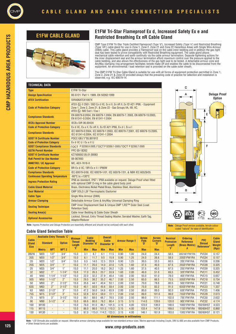
CMPCM
PHA
ZARD
OUSAR
EAPR
ODUC
TSC A B L E G L A N D A N D C A B L E C O N N E C T I O N S P E C I A L I S T S
125 www.cmp-products.com
CMP Type E1FW Tri-Star Triple Certified Flameproof (Type ‘d’), Increased Safety (Type ‘e’) and Restricted Breathing(Type ‘nR’) cable gland for use in Zone 1, Zone 2, Zone 21 and Zone 22 Hazardous Areas with Single Wire Armour(SWA) cable. This cable gland provides a Flameproof seal on the cable inner bedding and in addition the gas tightseal has been tested to prove compatibility with Restricted Breathing equipment. The cable gland allowsmechanical cable retention and earth continuity via the cable armour termination. Separate tightening actions forthe inner displacement seal and the armour termination afford maximum control over the pressure applied to thecable bedding, and also allows the effectiveness of the gas tight seal to be tested. A detachable armour cone andAnyWay clamping ring arrangement facilitates remote make off and enables the cable to be disconnected from theequipment. An environmental / load retention seal is provided on the cable outer sheath.
The CMP E1FW Tri-Star Cable Gland is suitable for use with all forms of equipment protection permitted in Zone 1,Zone 2, Zone 21 & Zone 22 provided always that the prevailing code of practice for selection and installation isobserved, e.g. IEC 60079-14.
TECHNICAL DATA
Type E1FW Tri-Star
Design Specification BS 6121: Part 1: 1989, EN 50262:1999
ATEX Certification SIRA06ATEX1097X
Code of Protection CategoryATEX II 2GD / 3GD Ex d IIC, Ex e II, Ex nR II, Ex tD A21 IP66, - EquipmentZone 1, Zone 2, Zone 21, & Zone 22 - Gas Groups IIA, IIB, IIC,ATEX IM2 Exd I / Exe I
Compliance Standards EN 60079-0:2004, EN 60079-1:2004, EN 60079-7: 2003, EN 60079-15:2003,EN 61241-0:2004, EN 61241-1:2004
IECEx Approval Number IECEx SIR 06.0043XCode of Protection Category Ex d IIC, Ex e II, Ex nR II, Ex tD A21 IP66, Ex d I, Ex e I
Compliance Standards IEC 60079-0:2004, IEC 60079-1:2003, IEC 60079-7:2001, IEC 60079-15:2005,IEC 61241-0:2004, IEC 61241-1:2004
GOST R Certificate Number POCC GB. 05.B01912Code of Protection Category Ex d IIC U / Ex e II UGOST Compliance Standards P 52350.0-2005, P 52350.1-2005, P 52350.7-2005
GGTN Permit Number PPC 00-18262GOST K Certificate Number KZ7500052.05.01.00063RoK Permit for Use Number 08-067693
INMETRO / UC Approval MC, AEX-7618-X
Code of Protection Category BR-Ex d IIC / BR-Ex e II / IP66W
Compliance Standards IEC 60079-0/00, IEC 60079-1/01, IEC 60079-7/01, & NBR IEC 60529/05Continuous Operating Temperature -60°C to +130°C
Ingress Protection Rating IP66 as standard, IP67 / IP68 available on request. Deluge Proof when fittedwith optional CMP O-ring in the cable gland body joint
Cable Gland Material Brass, Electroless Nickel Plated Brass, Stainless Steel, Aluminium
Seal Material CMP SOLO LSF Thermoplastic Elastomer
Cable Type Single Wire Armour (SWA)
Armour Clamping Detachable Armour Cone & AnyWay Universal Clamping Ring
Sealing Technique CMP Inner Displacement Seal & Unique CMP "LRS"™ Outer Seal (LoadRetention Seal)
Sealing Area(s) Cable Inner Bedding & Cable Outer Sheath
Optional Accessories Locknut, Shroud, Entry Thread Sealing Washer, Serrated Washer, Earth Tag,Adaptor/Reducer
CableGlandSize
Available Entry Threads ‘C’MinimumThreadLength‘E’
CableBedding
Diameter ‘A’
OverallCable
Diameter ‘B’Armour Range †
AcrossFlats‘D’
AcrossCorners
‘D’
NominalProtrusionLength’F’
OrderingReference
(Brass Metric)#
PVCShroud
Reference*
CableGlandWeight(Kgs)
Standard Option
Metric NPT NPT 2 Min Max Min Max Min Max Max Max
20S/16 M20 1/2” 3/4” 15.0 3.1 8.7 6.1 11.5 0.90 1.00 24.0 24.4 58.5 20S16E1FW1RA PVC04 0.15720S M20 1/2” 3/4” 15.0 6.1 11.7 9.5 15.9 0.90 1.25 24.0 26.6 58.5 20SE1FW1RA PVC04 0.15720 M20 1/2” 3/4” 15.0 6.5 14.0 12.5 20.9 0.90 1.25 30.5 33.3 60.5 20E1FW1RA PVC06 0.20625S M25 3/4” 1” 15.0 11.1 20.0 14.0 22.0 1.25 1.60 37.5 40.5 67.5 25SE1FW1RA PVC09 0.32525 M25 3/4” 1” 15.0 11.1 20.0 18.2 26.2 1.25 1.60 37.5 40.5 67.5 25E1FW1RA PVC09 0.32532 M32 1” 1-1/4” 15.0 17.0 26.3 23.7 33.9 1.60 2.00 46.0 51.0 69.5 32E1FW1RA PVC11 0.45240 M40 1-1/4” 1-1/2” 15.0 22.0 32.2 27.9 40.4 1.60 2.00 55.0 61.0 78.0 40E1FW1RA PVC15 0.65750S M50 1-1/2” 2” 15.0 29.5 38.2 35.2 46.7 2.00 2.50 60.0 66.5 75.5 50SE1FW1RA PVC18 0.73450 M50 2” 2-1/2” 15.0 35.6 44.1 40.4 53.1 2.00 2.50 70.0 78.6 80.5 50E1FW1RA PVC21 0.74863S M63 2” 2-1/2” 15.0 40.1 50.0 45.6 59.4 2.00 2.50 75.0 83.2 91.5 63SE1FW1RA PVC23 1.33763 M63 2-1/2” 3” 15.0 47.2 56.0 54.6 65.9 2.00 2.50 80.0 89.0 92.0 63E1FW1RA PVC25 1.43675S M75 2-1/2” 3” 15.0 52.8 62.0 59.0 72.1 2.00 2.50 89.0 101.6 99.0 75SE1FW1RA PVC28 2.07375 M75 3” 3-1/2” 15.0 59.1 68.0 66.7 78.5 2.00 2.50 99.0 111.1 102.0 75E1FW1RA PVC30 2.62290 M90 3-1/2” 4” 15.0 66.6 80.0 76.2 90.4 3.15 3.15 114.0 128.6 120.0 90E1FW1RA PVC32 4.174100 M100 - - 15.0 76.0 91.0 86.1 101.5 3.15 4.00 123.0 138.0 148.0 100E1FW1RA 150/50HST 4.523115 M115 - - 15.0 86.0 98.0 101.5 110.3 3.15 4.00 133.4 147.8 169.0 115E1FW1RA 180/60HST 6.860130 M130 - - 15.0 97.0 115.0 114.2 123.3 3.15 4.00 146.1 161.9 183.0 130E1FW1RA 180/60HST 8.121
All dimensions in millimetres
E1FW Tri-Star Flameproof Ex d, Increased Safety Ex e andRestricted Breathing Ex nR Cable GlandE1FW CABLE GLAND
AA
BB
DD
CC
EE
FF
Cable Gland Selection Table
OCTL
OCTL
OCTL
Note: *LSF Shrouds also available on request. Alternative armour clamping range available for non-standard armour sizes. Marine approvals including Lloyds, DNV & ABS are also available from CMP Products.# Other thread forms are available.
LLU
Deluge ProofOption
LLU05
Note: Deluge Proof version available, ferrule colourcoded “natural” for ease of identification
Note: Ingress Protection and Deluge Protection are essentially different and should not be confused with each other.
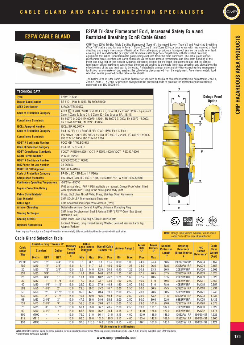
CMPHA
ZARD
OUSAR
EAPR
ODUC
TS
CMPC A B L E G L A N D A N D C A B L E C O N N E C T I O N S P E C I A L I S T S
126www.cmp-products.com
CMP Type E2FW Tri-Star Triple Certified Flameproof (Type ‘d’), Increased Safety (Type ‘e’) and Restricted Breathing(Type ‘nR’) cable gland for use in Zone 1, Zone 2, Zone 21 and Zone 22 Hazardous Areas with lead covered or leadsheathed and single wire armour (SWA) cable. This cable gland provides a flameproof seal on the cable inner leadcovering and in addition the gas tight seal has been tested to prove compatibility with Restricted Breathingequipment that relies upon flammable gases being excluded from the main enclosure. The cable gland allowsmechanical cable retention and earth continuity via the cable armour termination, and also earth bonding of theinner lead covering or lead sheath. Separate tightening actions for the inner displacement seal and the armourtermination afford maximum control over the pressure applied to the cable inner lead covering, and also allows theeffectiveness of the gas tight seal to be tested. A detachable armour cone and AnyWay clamping ring arrangementfacilitates remote make off and enables the cable to be disconnected from the equipment. An environmental / loadretention seal is provided on the cable outer sheath.
The CMP E2FW Tri-Star Cable Gland is suitable for use with all forms of equipment protection permitted in Zone 1,Zone 2, Zone 21 & Zone 22 provided always that the prevailing code of practice for selection and installation isobserved, e.g. IEC 60079-14.
TECHNICAL DATA
Type E2FW Tri-Star
Design Specification BS 6121: Part 1: 1989, EN 50262:1999
ATEX Certification SIRA06ATEX1097X
Code of Protection Category ATEX II 2GD / 3 GD Ex d IIC, Ex e II, Ex nR II, Ex tD A21 IP66, - EquipmentZone 1, Zone 2, Zone 21, & Zone 22 - Gas Groups IIA, IIB, IIC
Compliance Standards EN 60079-0: 2004, EN 60079-1:2004, EN 60079-7: 2003, EN 60079-15:2003,EN 61241-0:2004, EN 61241-1:2004
IECEx Approval Number IECEx SIR 06.0043XCode of Protection Category Ex d IIC / Ex e II / Ex nR II / Ex tD A21 IP66, Ex d I / Ex e I
Compliance Standards IEC 60079-0:2004, IEC 60079-1:2003, IEC 60079-7:2001, IEC 60079-15:2005,IEC 61241-0:2004, IEC 61241-1:2004
GOST R Certificate Number POCC GB. 05.B01912
Code of Protection Category Ex d IIC U / Ex e II UGOST Compliance Standards P 52350.0-2005, P 52350.1-2005, P 52350.7-2005
GGTN Permit Number PPC 00-18262GOST K Certificate Number KZ7500052.05.01.00063RoK Permit for Use Number 08-067693INMETRO / UC Approval MC, AEX-7618-XCode of Protection Category BR-Ex d IIC / BR-Ex e II / IP66WCompliance Standards IEC 60079-0/00, IEC 60079-1/01, IEC 60079-7/01, & NBR IEC 60529/05Continuous Operating Temperature -60°C to +130°C
Ingress Protection Rating IP66 as standard, IP67 / IP68 available on request. Deluge Proof when fittedwith optional CMP O-ring in the cable gland body joint
Cable Gland Material Brass, Electroless Nickel Plated Brass, Stainless Steel, AluminiumSeal Material CMP SOLO LSF Thermoplastic ElastomerCable Type Lead Sheathed and Single Wire Armour (SWA)Armour Clamping Detachable Armour Cone & AnyWay Universal Clamping Ring
Sealing Technique CMP Inner Displacement Seal & Unique CMP "LRS"™ Outer Seal (LoadRetention Seal)
Sealing Area(s) Cable Inner Lead Covering & Cable Outer Sheath
Optional Accessories Locknut, Shroud, Entry Thread Sealing Washer, Serrated Washer, Earth Tag,Adaptor/Reducer
CableGlandSize
Available Entry Threads ‘C’MinimumThreadLength‘E’
CableLead SheathDiameter
‘A’
Overall CableDiameter ‘B’ Armour Range †
AcrossFlats‘D’
AcrossCorners
‘D’
NominalProtrusionLength‘F’
OrderingReference
(Brass Metric)#
PVCShroud
Reference*
CableGlandWeight(Kgs)
Standard Option
Metric NPT NPT Min Max Min Max Min Max Max Max
20S/16 M20 1/2” 3/4” 15.0 3.1 8.7 6.1 11.5 0.90 1.00 24.0 24.4 58.5 20S16E2FW1RA PVC04 0.15720S M20 1/2” 3/4” 15.0 6.1 11.7 9.5 15.9 0.90 1.25 24.0 26.6 58.5 20SE2FW1RA PVC04 0.15720 M20 1/2” 3/4” 15.0 6.5 14.0 12.5 20.9 0.90 1.25 30.5 33.3 60.5 20E2FW1RA PVC06 0.20625S M25 3/4” 1” 15.0 11.1 20.0 14.0 22.0 1.25 1.60 37.5 40.5 67.5 25SE2FW1RA PVC09 0.32525 M25 3/4” 1” 15.0 11.1 20.0 18.2 26.2 1.25 1.60 37.5 40.5 67.5 25E2FW1RA PVC09 0.32532 M32 1” 1-1/4” 15.0 17.0 26.3 23.7 33.9 1.60 2.00 46.0 51.0 69.5 32E2FW1RA PVC11 0.45240 M40 1-1/4” 1-1/2” 15.0 22.0 32.2 27.9 40.4 1.60 2.00 55.0 61.0 78.0 40E2FW1RA PVC15 0.65750S M50 1-1/2” 2” 15.0 29.5 38.2 35.2 46.7 2.00 2.50 60.0 66.5 75.5 50SE2FW1RA PVC18 0.73450 M50 2” 2-1/2” 15.0 35.6 44.1 40.4 53.1 2.00 2.50 70.0 78.6 80.5 50E2FW1RA PVC21 0.74863S M63 2” 2-1/2” 15.0 40.1 50.0 45.6 59.4 2.00 2.50 75.0 83.2 91.5 63SE2FW1RA PVC23 1.33763 M63 2-1/2” 3” 15.0 47.2 56.0 54.6 65.9 2.00 2.50 80.0 89.0 92.0 63E2FW1RA PVC25 1.43675S M75 2-1/2” 3” 15.0 52.8 62.0 59.0 72.1 2.00 2.50 89.0 101.6 99.0 75SE2FW1RA PVC28 2.07375 M75 3” 3-1/2” 15.0 59.1 68.0 66.7 78.5 2.00 2.50 99.0 111.1 102.0 75E2FW1RA PVC30 2.62290 M90 3-1/2” 4 15.0 66.6 80.0 76.2 90.4 3.15 3.15 114.0 128.6 120.0 90E2FW1RA PVC32 4.174100 M100 - - 15.0 76.0 91.0 86.1 101.5 3.15 4.00 123.0 138.0 148.0 100E2FW1RA 150/50HST 4.523115 M115 - - 15.0 86.0 98.0 101.5 110.3 3.15 4.00 133.4 147.8 169.0 115E2FW1RA 180/60HST 6.860130 M130 - - 15.0 97.0 115.0 114.2 123.3 3.15 4.00 146.1 161.9 183.0 130E2FW1RA 180/60HST 8.121
All dimensions in millimetres
E2FW Tri-Star Flameproof Ex d, Increased Safety Ex e andRestricted Breathing Ex nR Cable GlandE2FW CABLE GLAND
BB
DD
AA
CC
EE
FF
Note: Alternative armour clamping range available for non-standard armour sizes. Marine approvals including Lloyds, DNV & ABS are also available from CMP Products.# Other thread forms are available
Cable Gland Selection Table
LLU
Deluge ProofOption
LLU05
OCTL
OCTL
OCTL
Note: Deluge Proof version available, ferrule colourcoded “natural” for ease of identification
Note: Ingress Protection and Deluge Protection are essentially different and should not be confused with each other.

CMPCM
PHA
ZARD
OUSAR
EAPR
ODUC
TSC A B L E G L A N D A N D C A B L E C O N N E C T I O N S P E C I A L I S T S
127 www.cmp-products.com
TECHNICAL DATAType E1FX Tri-StarDesign Specification BS 6121: Part 1: 1989, EN 50262:1999ATEX Certification SIRA06ATEX1097X
Code of Protection Category ATEX II 2GD / 3GD Ex d IIC, Ex e II, Ex nR II Ex tD A21 IP66, - EquipmentZone 1, Zone 2, Zone 21, & Zone 22 - Gas Groups IIA, IIB, IIC, IM2, Ex d I / Ex e I
Compliance Standards EN 60079-0: 2004, EN 60079-1:2004, EN 60079-7: 2003, EN 60079-15:2003,EN 61241-0:2004, EN 61241-1:2004
IECEx Approval Number IECEx SIR 06.0043XCode of Protection Category Ex d IIC, Ex e II, Ex nR II, Ex tD A21 IP66, Ex d I, Ex e I
Compliance Standards IEC 60079-0:2004, IEC 60079-1:2003, IEC 60079-7:2001, IEC 60079-15:2005,IEC61241-0:2004, IEC 61241-1:2004
GOST R Certificate Number POCC GB. 05.B01912Code of Protection Category Ex d IIC U / EX e II UCompliance Standards P 52350.0-2005, P 52350.1-2005, P 52350.7-2005
GGTN Permit Number PPC 00-18262
GOST K Certificate Number KZ7500052.05.01.00063
RoK Permit for Use Number 08-067693
INMETRO / UC Approval MC, AEX-7618-X
Code of Protection Category BR-Ex d IIC / BR-Ex e II / IP66W
Compliance Standards IEC 60079-0/00, IEC 60079-1/01, IEC 60079-7/01, & NBR IEC 60529/05
Continuous Operating Temperature -60°C to +130°C
Ingress Protection Rating IP66 as standard, IP67 / IP68 available on request. Deluge Proof when fitted withoptional CMP O-ring in the cable gland body joint
Cable Gland Material Brass, Electroless Nickel Plated Brass, Stainless Steel, Aluminium
Seal Material CMP SOLO LSF Thermoplastic Elastomer
Cable TypeWire Braid Armour, Screened Flexible Wire Braid (e.g. CY / SY), Pliable Wire ArmourPWA,), Steel Tape Armour (STA), Aluminium Strip Armour (ASA), Armored &Jacketed.
Armour Clamping Detachable Armour Cone & AnyWay Universal Clamping Ring
Sealing Technique CMP Inner Displacement Seal & Unique CMP "LRS" ™ Outer Seal (Load RetentionSeal)
Sealing Area(s) Cable Inner Bedding & Cable Outer Sheath
Optional Accessories Locknut, Shroud, Entry Thread Sealing Washer, Serrated Washer, Earth Tag,Adaptor/Reducer
CMP Type E1FX Tri-Star Triple Certified Flameproof (Type ‘d’), Increased Safety (Type ‘e’) and RestrictedBreathing (Type ‘nR’) indoor and outdoor cable gland for use in Zone 1, Zone 2, Zone 21 and Zone 22Hazardous Areas with Braided, Pliable Wire Armour (PWA), Strip Armour and Steel Tape Armour (STA) cable.This cable gland provides a Flameproof seal on the cable inner bedding and in addition the gas tight seal hasbeen tested to prove compatibility with Restricted Breathing equipment. The cable gland allows mechanicalcable retention and earth continuity via the cable armour termination. Separate tightening actions for the innerdisplacement seal and the armour termination afford maximum control over the pressure applied to cablebedding, and also allows the effectiveness of the gas tight seal to be tested. A detachable armour cone andAnyWay clamping ring arrangement facilitates remote make off and enables the cable to be disconnected fromthe equipment. An environmental / load retention seal is provided on the cable outer sheath.
The CMP E1FX Tri-Star Cable Gland is suitable for use with all forms of equipment protection permitted inZone 1, Zone 2, Zone 21 & Zone 22 provided always that the prevailing code of practice for selection andinstallation is observed, e.g. IEC 60079-14.
CableGlandSize
Available Entry Threads ‘C’MinimumThread
Length ‘E’
CableBedding
Diameter ‘A’
Overall CableDiameter ‘B’
ArmourRange
AcrossFlats‘D’
AcrossCorners
‘D’
NominalProtrusionLength‘F’
OrderingReference
(Brass Metric)#
PVCShroud
Reference*
CableGlandWeight(Kgs)
Standard Option
Metric NPT NPT Min Max Min Max Min Max Max Max20S/16 M20 1/2” 3/4” 15.0 3.1 8.7 6.1 11.5 0.0 1.0 24.0 24.4 58.5 20S16E1FX1RA PVC04 0.15820S M20 1/2” 3/4” 15.0 6.1 11.7 9.5 15.9 0.0 1.0 24.0 26.6 58.5 20SE1FX1RA PVC04 0.15820 M20 1/2” 3/4” 15.0 6.5 14.0 12.5 20.9 0.0 1.0 30.5 33.3 60.5 20E1FX1RA PVC06 0.20825S M25 3/4” 1” 15.0 11.1 20.0 14.0 22.0 0.0 1.0 37.5 40.5 67.5 25SE1FX1RA PVC09 0.33025 M25 3/4” 1” 15.0 11.1 20.0 18.2 26.2 0.0 1.0 37.5 40.5 67.5 25E1FX1RA PVC09 0.33032 M32 1” 1-1/4” 15.0 17.0 26.3 23.7 33.9 0.0 1.0 46.0 51.0 69.5 32E1FX1RA PVC11 0.46340 M40 1-1/4” 1-1/2” 15.0 22.0 32.2 27.9 40.4 0.0 1.0 55.0 61.0 78.0 40E1FX1RA PVC15 0.67150S M50 1-1/2” 2” 15.0 29.5 38.2 35.2 46.7 0.0 1.0 60.0 66.5 75.5 50SE1FX1RA PVC18 0.76050 M50 2” 2-1/2” 15.0 35.6 44.1 40.4 53.1 0.0 1.0 70.0 78.6 80.5 50E1FX1RA PVC21 0.77763S M63 2” 2-1/2” 15.0 40.1 50.0 45.6 59.4 0.0 1.0 75.0 83.2 91.5 63SE1FX1RA PVC23 1.36963 M63 2-1/2” 3” 15.0 47.2 56.0 54.6 65.9 0.0 1.0 80.0 89.0 92.0 63E1FX1RA PVC25 1.47275S M75 2-1/2” 3” 15.0 52.8 62.0 59.0 72.1 0.0 1.0 89.0 101.6 99.0 75SE1FX1RA PVC28 2.11975 M75 3” 3-1/2” 15.0 59.1 68.0 66.7 78.5 0.0 1.0 99.0 111.1 102.0 75E1FX1RA PVC30 2.68890 M90 3-1/2” 4” 15.0 66.6 80.0 76.2 90.4 0.0 1.6 114.0 128.6 120.0 90E1FX1RA PVC32 4.281100 M100 - - 15.0 76.0 91.0 86.1 101.5 0.0 1.6 123.0 138.0 148.0 100E1FX1RA 150/50HST 4.674115 M115 - - 15.0 86.0 98.0 101.5 110.3 0.0 1.6 133.4 147.8 169.0 115E1FX1RA 180/60HST 7.085130 M130 - - 15.0 97.0 115.0 114.2 123.3 0.0 1.6 146.1 161.9 183.0 130E1FX1RA 180/60HST 8.382
All dimensions in millimetres
E1FX Tri-Star Flameproof Ex d, Increased Safety Ex e andRestricted Breathing Ex nR Cable GlandE1FX CABLE GLAND
AA
BB
DD
CC
EE
FF
Cable Gland Selection Table
Note: *LSF Shrouds also available on request. Alternative armour clamping range available for non-standard armour sizes. Marine approvals including Lloyds, DNV & ABS are also available from CMP Products.# Other thread forms are available
LLU
Deluge ProofOption
LLU05
OCTL
OCTL
OCTL
Note: Ingress Protection and Deluge Protection are essentially different and should not be confused with each other. Note: Deluge Proof version available, ferrule colourcoded “natural” for ease of identification
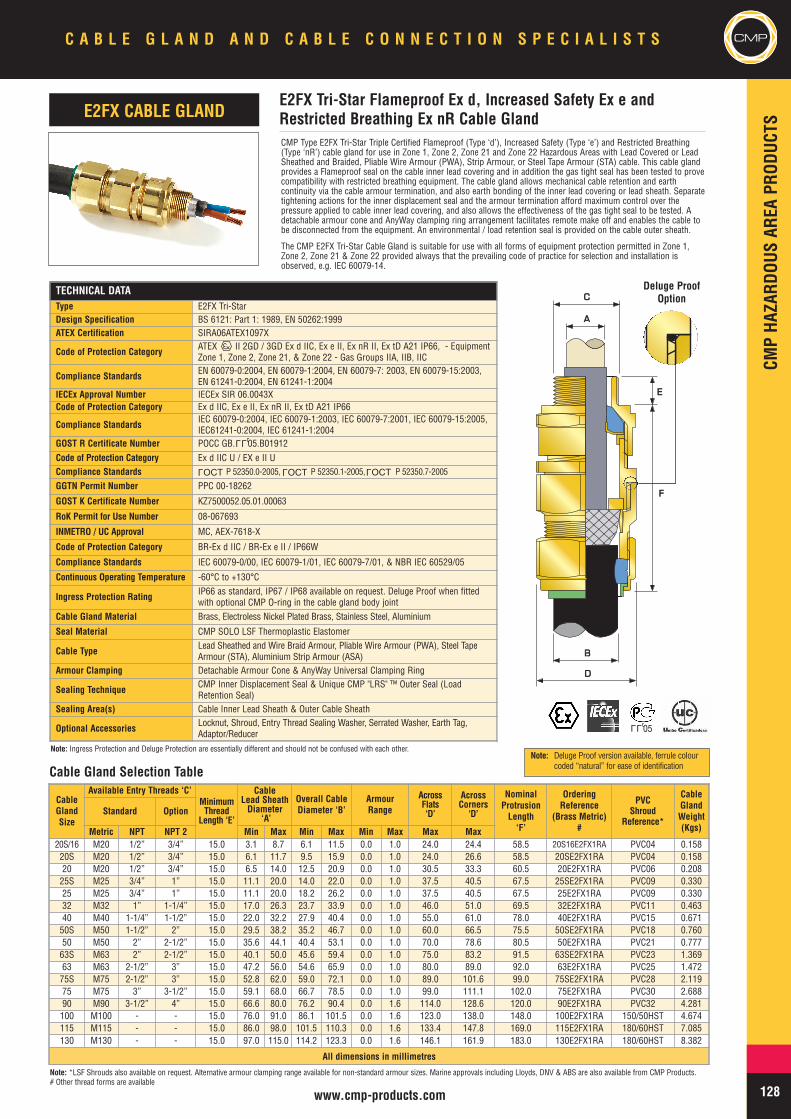
CMPHA
ZARD
OUSAR
EAPR
ODUC
TS
CMPC A B L E G L A N D A N D C A B L E C O N N E C T I O N S P E C I A L I S T S
128www.cmp-products.com
Note: *LSF Shrouds also available on request. Alternative armour clamping range available for non-standard armour sizes. Marine approvals including Lloyds, DNV & ABS are also available from CMP Products.# Other thread forms are available
TECHNICAL DATAType E2FX Tri-StarDesign Specification BS 6121: Part 1: 1989, EN 50262:1999ATEX Certification SIRA06ATEX1097X
Code of Protection Category ATEX II 2GD / 3GD Ex d IIC, Ex e II, Ex nR II, Ex tD A21 IP66, - EquipmentZone 1, Zone 2, Zone 21, & Zone 22 - Gas Groups IIA, IIB, IIC
Compliance Standards EN 60079-0:2004, EN 60079-1:2004, EN 60079-7: 2003, EN 60079-15:2003,EN 61241-0:2004, EN 61241-1:2004
IECEx Approval Number IECEx SIR 06.0043XCode of Protection Category Ex d IIC, Ex e II, Ex nR II, Ex tD A21 IP66
Compliance Standards IEC 60079-0:2004, IEC 60079-1:2003, IEC 60079-7:2001, IEC 60079-15:2005,IEC61241-0:2004, IEC 61241-1:2004
GOST R Certificate Number POCC GB. 05.B01912Code of Protection Category Ex d IIC U / EX e II UCompliance Standards P 52350.0-2005, P 52350.1-2005, P 52350.7-2005
GGTN Permit Number PPC 00-18262
GOST K Certificate Number KZ7500052.05.01.00063
RoK Permit for Use Number 08-067693
INMETRO / UC Approval MC, AEX-7618-X
Code of Protection Category BR-Ex d IIC / BR-Ex e II / IP66W
Compliance Standards IEC 60079-0/00, IEC 60079-1/01, IEC 60079-7/01, & NBR IEC 60529/05
Continuous Operating Temperature -60°C to +130°C
Ingress Protection Rating IP66 as standard, IP67 / IP68 available on request. Deluge Proof when fittedwith optional CMP O-ring in the cable gland body joint
Cable Gland Material Brass, Electroless Nickel Plated Brass, Stainless Steel, Aluminium
Seal Material CMP SOLO LSF Thermoplastic Elastomer
Cable Type Lead Sheathed and Wire Braid Armour, Pliable Wire Armour (PWA), Steel TapeArmour (STA), Aluminium Strip Armour (ASA)
Armour Clamping Detachable Armour Cone & AnyWay Universal Clamping Ring
Sealing Technique CMP Inner Displacement Seal & Unique CMP "LRS" ™ Outer Seal (LoadRetention Seal)
Sealing Area(s) Cable Inner Lead Sheath & Outer Cable Sheath
Optional Accessories Locknut, Shroud, Entry Thread Sealing Washer, Serrated Washer, Earth Tag,Adaptor/Reducer
CMP Type E2FX Tri-Star Triple Certified Flameproof (Type ‘d’), Increased Safety (Type ‘e’) and Restricted Breathing(Type ‘nR’) cable gland for use in Zone 1, Zone 2, Zone 21 and Zone 22 Hazardous Areas with Lead Covered or LeadSheathed and Braided, Pliable Wire Armour (PWA), Strip Armour, or Steel Tape Armour (STA) cable. This cable glandprovides a Flameproof seal on the cable inner lead covering and in addition the gas tight seal has been tested to provecompatibility with restricted breathing equipment. The cable gland allows mechanical cable retention and earthcontinuity via the cable armour termination, and also earth bonding of the inner lead covering or lead sheath. Separatetightening actions for the inner displacement seal and the armour termination afford maximum control over thepressure applied to cable inner lead covering, and also allows the effectiveness of the gas tight seal to be tested. Adetachable armour cone and AnyWay clamping ring arrangement facilitates remote make off and enables the cable tobe disconnected from the equipment. An environmental / load retention seal is provided on the cable outer sheath.
The CMP E2FX Tri-Star Cable Gland is suitable for use with all forms of equipment protection permitted in Zone 1,Zone 2, Zone 21 & Zone 22 provided always that the prevailing code of practice for selection and installation isobserved, e.g. IEC 60079-14.
CableGlandSize
Available Entry Threads ‘C’MinimumThread
Length ‘E’
CableLead SheathDiameter
‘A’
Overall CableDiameter ‘B’
ArmourRange
AcrossFlats‘D’
AcrossCorners
‘D’
NominalProtrusionLength‘F’
OrderingReference
(Brass Metric)#
PVCShroud
Reference*
CableGlandWeight(Kgs)
Standard Option
Metric NPT NPT 2 Min Max Min Max Min Max Max Max20S/16 M20 1/2” 3/4” 15.0 3.1 8.7 6.1 11.5 0.0 1.0 24.0 24.4 58.5 20S16E2FX1RA PVC04 0.15820S M20 1/2” 3/4” 15.0 6.1 11.7 9.5 15.9 0.0 1.0 24.0 26.6 58.5 20SE2FX1RA PVC04 0.15820 M20 1/2” 3/4” 15.0 6.5 14.0 12.5 20.9 0.0 1.0 30.5 33.3 60.5 20E2FX1RA PVC06 0.20825S M25 3/4” 1” 15.0 11.1 20.0 14.0 22.0 0.0 1.0 37.5 40.5 67.5 25SE2FX1RA PVC09 0.33025 M25 3/4” 1” 15.0 11.1 20.0 18.2 26.2 0.0 1.0 37.5 40.5 67.5 25E2FX1RA PVC09 0.33032 M32 1” 1-1/4” 15.0 17.0 26.3 23.7 33.9 0.0 1.0 46.0 51.0 69.5 32E2FX1RA PVC11 0.46340 M40 1-1/4” 1-1/2” 15.0 22.0 32.2 27.9 40.4 0.0 1.0 55.0 61.0 78.0 40E2FX1RA PVC15 0.67150S M50 1-1/2” 2” 15.0 29.5 38.2 35.2 46.7 0.0 1.0 60.0 66.5 75.5 50SE2FX1RA PVC18 0.76050 M50 2” 2-1/2” 15.0 35.6 44.1 40.4 53.1 0.0 1.0 70.0 78.6 80.5 50E2FX1RA PVC21 0.77763S M63 2” 2-1/2” 15.0 40.1 50.0 45.6 59.4 0.0 1.0 75.0 83.2 91.5 63SE2FX1RA PVC23 1.36963 M63 2-1/2” 3” 15.0 47.2 56.0 54.6 65.9 0.0 1.0 80.0 89.0 92.0 63E2FX1RA PVC25 1.47275S M75 2-1/2” 3” 15.0 52.8 62.0 59.0 72.1 0.0 1.0 89.0 101.6 99.0 75SE2FX1RA PVC28 2.11975 M75 3” 3-1/2” 15.0 59.1 68.0 66.7 78.5 0.0 1.0 99.0 111.1 102.0 75E2FX1RA PVC30 2.68890 M90 3-1/2” 4” 15.0 66.6 80.0 76.2 90.4 0.0 1.6 114.0 128.6 120.0 90E2FX1RA PVC32 4.281100 M100 - - 15.0 76.0 91.0 86.1 101.5 0.0 1.6 123.0 138.0 148.0 100E2FX1RA 150/50HST 4.674115 M115 - - 15.0 86.0 98.0 101.5 110.3 0.0 1.6 133.4 147.8 169.0 115E2FX1RA 180/60HST 7.085130 M130 - - 15.0 97.0 115.0 114.2 123.3 0.0 1.6 146.1 161.9 183.0 130E2FX1RA 180/60HST 8.382
All dimensions in millimetres
E2FX Tri-Star Flameproof Ex d, Increased Safety Ex e andRestricted Breathing Ex nR Cable GlandE2FX CABLE GLAND
BB
DD
AA
CC
EE
FF
Cable Gland Selection Table
LLU
Deluge ProofOption
LLU05
OCTL
OCTL
OCTL
Note: Ingress Protection and Deluge Protection are essentially different and should not be confused with each other.Note: Deluge Proof version available, ferrule colour
coded “natural” for ease of identification
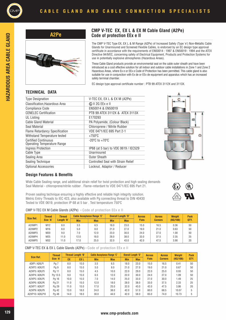
CMPHA
ZARD
OUSAR
EACA
BLEGL
AND
C A B L E G L A N D A N D C A B L E C O N N E C T I O N S P E C I A L I S T S
129 www.cmp-products.com
The CMP V-TEC Type EX, EX L & M Range (A2Pe) of Increased Safety (Type ‘e’) Non-Metallic CableGlands for Unarmoured and Screened Flexible Cables, is endorsed by an EC design type approvalcertificate in accordance with the requirements of EN50014 : 1997 & EN50019 : 1994 and the ATEXDirective 94/9/EC, concerning safety of Electrical Equipment, Products and Protection Systems foruse in potentially explosive atmospheres (Hazardous Areas).
These Cable Gland products provide an environmental seal on the cable outer sheath and have beenintroduced as a cost effective solution for all indoor and outdoor cable installations in Zone 1 and Zone 2Hazardous Areas, where Ex e or EEx e Code of Protection has been permitted. This cable gland is alsosuitable for use in conjunction with Ex de or EEx de equipment and apparatus which has an increasedsafety terminal chamber.
EC design type approval certificate number : PTB 99 ATEX 3112X and 3113X.
Design Features & Benefits
Wide Cable Sealing range, and additional strain relief for twist protection and high sealing demandsSeal Material - chloroprene/nitrile rubber . Flame–retardant to VDE 0471/IEC 695 Part 21.
Proven sealing technique ensuring a highly effective and reliable high integrity solution.Metric Entry Threads to IEC 423, also available with Pg connecting thread to DIN 40430Tested to VDE 0619, protection IP 68 at 5 bar . Test temperature 750ºC
TECHNICAL DATAType Designation V-TEC EX, EX L & EX M (A2Pe)Classification,Hazardous Area II 2G EEx e IICompliance Code EN50014 & EN50019CENELEC Certification PTB 99 ATEX 3112X & ATEX 3113XUL Listing E170293Cable Gland Material PA Polyamide, (Colour Black)Seal Material Chloroprene / Nitrile RubberFlame Retardancy Specification VDE 0471/IEC 695 Part 2-1Withstand Temperature tested +750ºCCertified Continuous -20ºC to +70ºCOperating Temperature RangeIngress Protection IP68 (at 5 bar) to VDE 0619 / IEC529Cable Type UnarmouredSealing Area Outer SheathSealing Technique Controlled Seal with Strain ReliefOptional Accessories Locknut, Adaptor / Reducer
DV
Size Ref.Thread Thread Cable Acceptance Range ‘C’ Overall Length ‘D’ Across Across Weight PackSize ‘A’ Length ‘B’ Min Max Min Max Flats Corners (KG/100) QTY.
A2XMP1 M12 8.0 3.5 6.5 18.0 23.0 15.0 16.5 0.36 50A2XMP2 M16 8.0 5.0 8.0 21.0 27.0 19.0 21.0 0.63 50A2XMP3 M20 9.0 7.0 12.0 23.0 30.0 24.0 27.0 1.00 50A2XMP4 M25 11.0 12.0 18.0 28.0 38.0 33.0 37.5 2.35 25A2XMP5 M32 11.0 17.0 25.0 32.0 43.0 42.0 47.5 3.90 20
Size Ref.Thread Thread Length ‘B’ Cable Acceptance Range ‘C’ Overall Length ‘D’ Across Across Weight PackSize ‘A’ EX EX L Min Max Min Max Flats Corners (KG/100) QTY.
A2XP1 / A2XLP1 Pg 7 8.0 15.0 3.5 6.5 18.0 23.0 15.0 16.5 0.41 50A2XP2 / A2XLP2 Pg 9 8.0 15.0 5.0 8.0 21.0 27.0 19.0 21.0 0.67 50A2XP3 / A2XLP3 Pg 11 8.0 15.0 4.5 10.0 22.0 29.0 22.0 25.0 0.93 50A2XP4 / A2XLP4 Pg 13.5 9.0 15.0 6.5 12.0 22.0 30.0 24.0 27.0 1.09 50A2XP5 / A2XLP5 Pg 16 10.0 15.0 7.0 14.0 25.0 33.0 27.0 30.0 1.49 25A2XP6 / A2XLP6 Pg 21 11.0 15.0 12.0 18.0 28.0 38.0 33.0 37.5 2.33 25A2XP7 / A2XLP7 Pg 29 11.0 15.0 17.0 25.0 32.0 43.0 42.0 47.5 3.86 20A2XP9 / A2XLP9 Pg 42 13.0 18.0 24.0 38.0 42.0 57.0 60.0 68.5 10.07 5A2XP10 / A2XLP10 Pg 48 14.0 18.0 30.0 44.0 42.0 58.0 65.0 74.0 10.73 5
CMP V-TEC EX & EX L Cable Glands (A2Pe) - Code of protection EEx e II
CMP V-TEC EX M Cable Glands (A2Pe) - Code of protection EEx e II
CMP V-TEC EX, EX L & EX M Cable Gland (A2Pe)Code of protection EEx e IIA2Pe
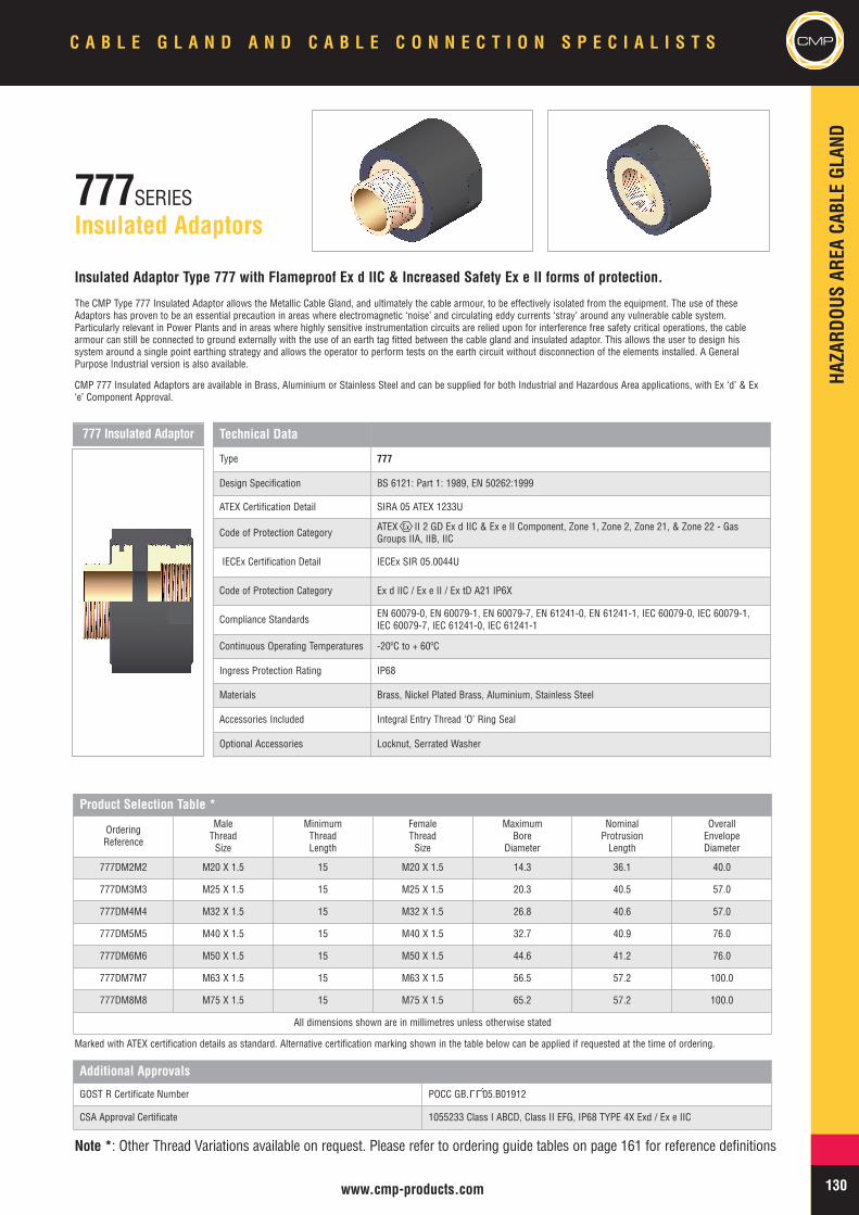
HAZA
RDOU
SAR
EACA
BLEGL
AND
130www.cmp-products.com
C A B L E G L A N D A N D C A B L E C O N N E C T I O N S P E C I A L I S T S CMP
777SERIESInsulated Adaptors
Insulated Adaptor Type 777 with Flameproof Ex d IIC & Increased Safety Ex e II forms of protection.
The CMP Type 777 Insulated Adaptor allows the Metallic Cable Gland, and ultimately the cable armour, to be effectively isolated from the equipment. The use of theseAdaptors has proven to be an essential precaution in areas where electromagnetic ‘noise’ and circulating eddy currents ‘stray’ around any vulnerable cable system.Particularly relevant in Power Plants and in areas where highly sensitive instrumentation circuits are relied upon for interference free safety critical operations, the cablearmour can still be connected to ground externally with the use of an earth tag fitted between the cable gland and insulated adaptor. This allows the user to design hissystem around a single point earthing strategy and allows the operator to perform tests on the earth circuit without disconnection of the elements installed. A GeneralPurpose Industrial version is also available.
CMP 777 Insulated Adaptors are available in Brass, Aluminium or Stainless Steel and can be supplied for both Industrial and Hazardous Area applications, with Ex ‘d’ & Ex‘e’ Component Approval.
Technical Data
Type 777
Design Specification BS 6121: Part 1: 1989, EN 50262:1999
ATEX Certification Detail SIRA 05 ATEX 1233U
Code of Protection Category ATEX II 2 GD Ex d IIC & Ex e II Component, Zone 1, Zone 2, Zone 21, & Zone 22 - GasGroups IIA, IIB, IIC
IECEx Certification Detail IECEx SIR 05.0044U
Code of Protection Category Ex d IIC / Ex e II / Ex tD A21 IP6X
Compliance Standards EN 60079-0, EN 60079-1, EN 60079-7, EN 61241-0, EN 61241-1, IEC 60079-0, IEC 60079-1,IEC 60079-7, IEC 61241-0, IEC 61241-1
Continuous Operating Temperatures -20ºC to + 60ºC
Ingress Protection Rating IP68
Materials Brass, Nickel Plated Brass, Aluminium, Stainless Steel
Accessories Included Integral Entry Thread ‘O’ Ring Seal
Optional Accessories Locknut, Serrated Washer
Product Selection Table *
OrderingReference
MaleThreadSize
MinimumThreadLength
FemaleThreadSize
MaximumBore
Diameter
NominalProtrusionLength
OverallEnvelopeDiameter
777DM2M2 M20 X 1.5 15 M20 X 1.5 14.3 36.1 40.0
777DM3M3 M25 X 1.5 15 M25 X 1.5 20.3 40.5 57.0
777DM4M4 M32 X 1.5 15 M32 X 1.5 26.8 40.6 57.0
777DM5M5 M40 X 1.5 15 M40 X 1.5 32.7 40.9 76.0
777DM6M6 M50 X 1.5 15 M50 X 1.5 44.6 41.2 76.0
777DM7M7 M63 X 1.5 15 M63 X 1.5 56.5 57.2 100.0
777DM8M8 M75 X 1.5 15 M75 X 1.5 65.2 57.2 100.0
All dimensions shown are in millimetres unless otherwise stated
Additional Approvals
GOST R Certificate Number POCC GB. 05.B01912
CSA Approval Certificate 1055233 Class I ABCD, Class II EFG, IP68 TYPE 4X Exd / Ex e IIC
Marked with ATEX certification details as standard. Alternative certification marking shown in the table below can be applied if requested at the time of ordering.
Note *: Other Thread Variations available on request. Please refer to ordering guide tables on page 161 for reference definitions
777 Insulated Adaptor
LLU
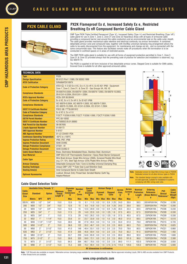
CMPCM
PHA
ZARD
OUSAR
EAPR
ODUC
TSC A B L E G L A N D A N D C A B L E C O N N E C T I O N S P E C I A L I S T S
131 www.cmp-products.com
TECHNICAL DATAType PX2KDesign Specification BS 6121:Part 1:1989, EN 50262:1999ATEX Cetification SIRA06ATEX1097X
Code of Protection Category ATEX II 2 GD Ex d IIC, Ex e II, Ex nR II, Ex tD A21 IP66 - EquipmentZone 1, Zone 2, Zone 21, & Zone 22 - Gas Groups IIA, IIB, IIC
Compliance Standards EN 60079-0:2004, EN 60079-1:2004, EN 60079-7:2003, EN 60079-15:2003,EN 61241-0:2004, EN 61241-1:2004
IECEx Approval Number IECEx SIR 06.0044XCode of Protection Category Ex d IIC, Ex e II, Ex nR II, Ex tD A21 IP66
Compliance Standards IEC 60079-0:2004, IEC 60079-1:2003, IEC 60079-7:2001,IEC 60079-15:2005, IEC 61241-0:2004, IEC 61241-1:2004
GOST R Certificate Number POCC GB. 05.B01912Code of Protection Category Ex d IIC U, Ex e II UCompliance Standards P 52350.0-2005, P 52350.1-2005, P 52350.7-2005
GGTN Permit Number PPC 00-18262GOST K Certificate Number KZ7500052.05.01.00063RoK Permit for Use Number 08-067693Lloyds Approval Number 01/00172DNV Approval Number E-6157ABS Approval Number 01-LD 234401-PDAContinuous Operating Temperature -60°C to +100°CIngress Protection Rating IP66, IP67, IP68Ingress Protection Document 5046 C549GDeluge Protection Compliance DTS01 : 91Deluge Protection Document 5046 C549G-DCable Gland Material Brass, Electroless Nickelplated Brass, Stainless Steel, AluminiumSeal Material CMP SOLO LSF Thermoplastic Elastomer / Epoxy Resin Barrier Compound
Cable Type Wire Braid Armour, Single Wire Armour (SWA), Screened Flexible Wire Braid(e.g. CY / SY), Steel Tape Armour (STA) Pliable Wire Armour (PWA)
Armour Clamping Detachable Compound Tube / Cone & AnyWay Universal Clamping RingSealing Technique Unique CMP "LRS" ™ Outer Seal (Load Retention Seal)Sealing Area(s) Inner Compound Barrier & Cable Outer Sheath
Optional Accessories Locknut, Shroud, Entry Thread Seal, Serrated Washer, Earth Tag,Adaptor/Reducer
CMP Type PX2K Triple Certified Flameproof (Type ‘d’), Increased Safety (Type ‘e’) and Restricted Breathing (Type ‘nR’)cable gland for use in Zone 1, Zone 2, Zone 21 and Zone 22 Hazardous Areas with all types of armoured cableproviding a compound barrier seal around the cable conductors and an environmental seal on the cable outer sheath.The cable gland provides mechanical cable retention and electrical continuity via armour termination. A combineddetachable armour cone and compound tube, together with AnyWay universal clamping ring arrangement allows thecable to be easily disconnected from the equipment, for maintenance and change out etc., and re-connected with thesame consummate ease. This feature also facilitates remote make off procedures when the termination is to beconducted in confined spaces or in areas of restricted access.
The CMP PX2K cable gland is suitable for use with all forms of equipment protection permitted in Zone 1, Zone 2,Zone 21 & Zone 22 provided always that the prevailing code of practice for selection and installation is observed, e.g.IEC 60079-14.
The PX2K is supplied in kit form inclusive of two detachable armour cones. Stepped Cone is suitable for SWA cables,Grooved Cone is suitable for all other approved armoured cables.
CableGlandSize
Available Entry Threads ‘C’MinimumThread
Length ‘E’
DiameterOver
Conductors‘A’
Numberof
Cores
OverallCable
Diameter‘B’
Armour Range †AcrossFlats‘D’
AcrossCorners
‘D’
NominalProtrusionLength‘F’
OrderingReference
(Brass Metric)#
PVCShroud
Reference*
CableGlandWeight(Kgs)
Standard Option GroovedCone
SteppedCone
Metric NPT NPT Max Max Min Max Min Max Min Max Max Max
20S/16 M20 1/2” 3/4” 15.0 12.6 15 6.1 11.5 0.0 1.0 0.9 1.25 24.0 26.6 58.5 20S16PX2K1RA PVC04 0.20020S M20 1/2” 3/4” 15.0 12.6 15 9.5 15.9 0.0 1.0 0.9 1.25 24.0 26.6 58.5 20SPX2K1RA PVC04 0.20020 M20 1/2” 3/4” 15.0 12.6 15 12.5 20.9 0.0 1.0 0.9 1.25 30.5 33.3 60.5 20PX2K1RA PVC06 0.23025S M25 3/4” 1” 15.0 17.5 29 14.0 22.0 0.0 1.0 1.25 1.6 37.5 40.5 67.5 25SPX2K1RA PVC09 0.33025 M25 3/4” 1” 15.0 17.5 29 18.2 26.2 0.0 1.0 1.25 1.6 37.5 40.5 67.5 25PX2K1RA PVC09 0.33032 M32 1” 1-1/4” 15.0 23.6 51 23.7 33.9 0.0 1.0 1.6 2.0 46.0 51.0 69.5 32PX2K1RA PVC11 0.51040 M40 1-1/4” 1-1/2” 15.0 30.0 80 27.9 40.4 0.0 1.0 1.6 2.0 55.0 61.0 78.0 40PX2K1RA PVC15 0.72050S M50 1-1/2” 2” 15.0 36.6 122 35.2 46.7 0.0 1.0 2.0 2.5 60.0 66.5 75.5 50SPX2K1RA PVC18 0.82550 M50 2” 2-1/2” 15.0 41.0 149 40.4 53.1 0.0 1.0 2.0 2.5 70.0 78.6 80.5 50PX2K1RA PVC21 0.86063S M63 2” 2-1/2” 15.0 47.9 205 45.6 59.4 0.0 1.0 2.0 2.5 75.0 83.2 91.5 63SPX2K1RA PVC23 1.45063 M63 2-1/2” 3” 15.0 53.7 259 54.6 65.9 0.0 1.0 2.0 2.5 80.0 89.0 92.0 63PX2K1RA PVC25 1.60075S M75 2-1/2” 3” 15.0 59.8 320 59.0 72.1 0.0 1.0 2.0 2.5 89.0 101.6 99.0 75SPX2K1RA PVC28 2.30075 M75 3” 3-1/2” 15.0 64.3 364 66.7 78.5 0.0 1.0 2.0 2.5 99.0 111.1 102.0 75PX2K1RA PVC30 3.05090 M90 3” 3-1/2” 15.0 75.3 500 76.2 90.4 0.0 1.6 3.15 3.15 114.0 128.6 120.0 90PX2K1RA PVC32 5.000
All dimensions in millimetres
PX2K Flameproof Ex d, Increased Safety Ex e, RestrictedBreathing Ex nR Compound Barrier Cable GlandPX2K CABLE GLAND
AA
BB
DD
CC
EE
FF
Cable Gland Selection Table
Note: *LSF Shrouds also available on request. †Alternative armour clamping range available for non-standard armour sizes. Marine approvals including Lloyds, DNV & ABS are also available from CMP Products.# Other thread forms are available
LLU
LLU05
OCTL
OCTL
OCTL
Note: Dedicated version for Steel Wire Armour type is PX2KW.Dedicated version for all other Armour types is PX2KX
Note: This standard design concept is also available withbi-code approvals, suitable for installation in systemscomplying with NEC wiring code rules.
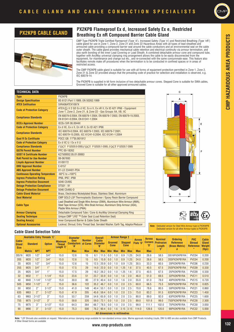
CMPHA
ZARD
OUSAR
EAPR
ODUC
TS
CMPC A B L E G L A N D A N D C A B L E C O N N E C T I O N S P E C I A L I S T S
132www.cmp-products.com
CableGlandSize
Available Entry Threads ‘C’
MinimumThread
Length ‘E’
DiameterOver
Conductors‘A’
Numberof Cores
OverallCable
Diameter‘B’
Armour Range †AcrossFlats ‘D’
AcrossCorners
‘D’
NominalProtrusionLength‘F’
OrderingReference
(Brass Metric)#
PVCShroud
Reference*
CableGlandWeight(Kgs)
Standard Option GroovedCone
SteppedCone
Metric NPT NPT Max Max Min Max Min Max Min Max Max Max
20S/16 M20 1/2” 3/4” 15.0 12.6 15 6.1 11.5 0.0 1.0 0.9 1.25 24.0 26.6 58.5 20S16PX2KPB1RA PVC04 0.20020S M20 1/2” 3/4” 15.0 12.6 15 9.5 15.9 0.0 1.0 0.9 1.25 24.0 26.6 58.5 20SPX2KPB1RA PVC04 0.20020 M20 1/2” 3/4” 15.0 12.6 15 12.5 20.9 0.0 1.0 0.9 1.25 30.5 33.3 60.5 20PX2KPB1RA PVC06 0.23025S M25 3/4” 1” 15.0 17.5 29 14.0 22.0 0.0 1.0 1.25 1.6 37.5 40.5 67.5 25SPX2KPB1RA PVC09 0.33025 M25 3/4” 1” 15.0 17.5 29 18.2 26.2 0.0 1.0 1.25 1.6 37.5 40.5 67.5 25PX2KPB1RA PVC09 0.33032 M32 1” 1-1/4” 15.0 23.6 51 23.7 33.9 0.0 1.0 1.6 2.0 46.0 51.0 69.5 32PX2KPB1RA PVC11 0.51040 M40 1-1/4” 1-1/2” 15.0 30.0 80 27.9 40.4 0.0 1.0 1.6 2.0 55.0 61.0 78.0 40PX2KPB1RA PVC15 0.72050S M50 1-1/2” 2” 15.0 36.6 122 35.2 46.7 0.0 1.0 2.0 2.5 60.0 66.5 75.5 50SPX2KPB1RA PVC18 0.82550 M50 2” 2-1/2” 15.0 41.0 149 40.4 53.1 0.0 1.0 2.0 2.5 70.0 78.6 80.5 50PX2KPB1RA PVC21 0.86063S M63 2” 2-1/2” 15.0 47.9 205 45.6 59.4 0.0 1.0 2.0 2.5 75.0 83.2 91.5 63SPX2KPB1RA PVC23 1.45063 M63 2-1/2” 3” 15.0 53.7 259 54.6 65.9 0.0 1.0 2.0 2.5 80.0 89.0 92.0 63PX2KPB1RA PVC25 1.60075S M75 2-1/2” 3” 15.0 59.8 320 59.0 72.1 0.0 1.0 2.0 2.5 89.0 101.6 99.0 75SPX2KPB1RA PVC28 2.30075 M75 3” 3-1/2” 15.0 64.3 364 66.7 78.5 0.0 1.0 2.0 2.5 99.0 111.1 102.0 75PX2KPB1RA PVC30 3.05090 M90 3” 3-1/2” 15.0 75.3 500 76.2 90.4 0.0 1.6 3.15 3.15 114.0 128.6 120.0 90PX2KPB1RA PVC32 5.000
All dimensions in millimetres
Note: *LSF Shrouds also available on request. †Alternative armour clamping range available for non-standard armour sizes. Marine approvals including Lloyds, DNV & ABS are also available from CMP Products.# Other thread forms are available
TECHNICAL DATAType PX2KPBDesign Specification BS 6121:Part 1:1989, EN 50262:1999ATEX Cetification SIRA06ATEX1097X
Code of Protection Category ATEX II 2 GD Ex d IIC, Ex e II, Ex nR II, Ex tD A21 IP66 - EquipmentZone 1, Zone 2, Zone 21, & Zone 22 - Gas Groups IIA, IIB, IIC
Compliance Standards EN 60079-0:2004, EN 60079-1:2004, EN 60079-7:2003, EN 60079-15:2003,EN 61241-0:2004, EN 61241-1:2004
IECEx Approval Number IECEx SIR 06.0044XCode of Protection Category Ex d IIC, Ex e II, En nR II, Ex tD A21 IP66
Compliance Standards IEC 60079-0:2004, IEC 60079-1:2003, IEC 60079-7:2001,IEC 60079-15:2005, IEC 61241-0:2004, IEC 61241-1:2004
Gost R Ex Certificate POCC GB. 05.B01912Code of Protection Category Ex d IIC U / Ex e II UCompliance Standards P 52520.0-2005, P 52520.1-2005, P 52520.7-2005
GGTN Permit Number PPC 00-18262GOST K Certificate Number KZ7500052.05.01.00063RoK Permit for Use Number 08-067693Lloyds Approval Number 01/00172DNV Approval Number E-6157ABS Approval Number 01-LD 234401-PDAContinuous Operating Temperature -60°C to +100°CIngress Protection Rating IP66, IP67, IP68Ingress Protection Document 5046 C549GDeluge Protection Compliance DTS01 : 91Deluge Protection Document 5046 C549G-DCable Gland Material Brass, Electroless Nickelplated Brass, Stainless Steel, AluminiumSeal Material CMP SOLO LSF Thermoplastic Elastomer / Epoxy Resin Barrier Compound
Cable TypeLead Sheathed and Single Wire Armour (SWA), AluminiumWire Armour (AWA),Steel Tape Armour (STA), Wire Braid Armour, Aluminium Strip Armour (ASA),Pliable Wire Armour (PWA)
Armour Clamping Detachable Compound Tube / Cone & AnyWay Universal Clamping RingSealing Technique Unique CMP "LRS" ™ Outer Seal (Load Retention Seal)Sealing Area(s) Inner Compound Barrier & Cable Outer SheathOptional Accessories Locknut, Shroud, Entry Thread Seal, Serrated Washer, Earth Tag, Adaptor/Reducer
LLU
CMP Type PX2KPB Triple Certified Flameproof (Type ‘d’), Increased Safety (Type ‘e’) and Restricted Breathing (Type ‘nR’)cable gland for use in Zone 1, Zone 2, Zone 21 and Zone 22 Hazardous Areas with all types of lead sheathed andarmoured cable providing a compound barrier seal around the cable conductors and an environmental seal on the cableouter sheath. The cable gland provides mechanical cable retention and electrical continuity via armour termination, andalso earth bonding of the inner Lead Covering or Lead Sheath. A combined detachable armour cone and compound tube,together with AnyWay universal clamping ring arrangement allows the cable to be easily disconnected from theequipment, for maintenance and change out etc., and re-connected with the same consummate ease. This feature alsofacilitates remote make off procedures when the termination is to be conducted in confined spaces or in areas ofrestricted access.
The CMP PX2KPB cable gland is suitable for use with all forms of equipment protection permitted in Zone 1, Zone 2,Zone 21 & Zone 22 provided always that the prevailing code of practice for selection and installation is observed, e.g.IEC 60079-14.
The PX2KPB is supplied in kit form inclusive of two detachable armour cones. Stepped Cone is suitable for SWA cables,Grooved Cone is suitable for all other approved armoured cables.
PX2KPB Flameproof Ex d, Increased Safety Ex e, RestrictedBreathing Ex nR Compound Barrier Cable GlandPX2KPB CABLE GLAND
AA
BB
DD
CC
EE
FF
Cable Gland Selection Table
LLU05
OCTL
OCTL
OCTL
Note: Dedicated version for Steel Wire Armour type is PX2KWPBDedicated version for all other Armour types is PX2KXPB
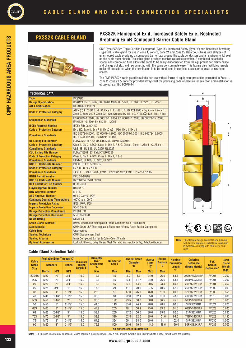
CMPCM
PHA
ZARD
OUSAR
EAPR
ODUC
TSC A B L E G L A N D A N D C A B L E C O N N E C T I O N S P E C I A L I S T S
133 www.cmp-products.com
TECHNICAL DATAType PXSS2KDesign Specification BS 6121:Part 1:1989, EN 50262:1999, UL 514B, UL 886, UL 2225, UL 2227ATEX Certification SIRA06ATEX1097X
Code of Protection Category ATEX I I 2 GD Ex d IIC, Ex e II, Ex nR II, Ex tD A21 IP66 - Equipment Zone 1,Zone 2, Zone 21, & Zone 22 - Gas Groups IIA, IIB, IIC, ATEX IM2, Exd I / Exe I
Compliance Standards EN 60079-0: 2004, EN 60079-1: 2004, EN 60079-7: 2003, EN 60079-15: 2003,EN 61241-0: 2004 EN 61241-1: 2004
IECEx Approval Number IECEx SIR 06.0044XCode of Protection Category Ex d IIC, Ex e II, Ex nR II, Ex tD A21 IP66, Ex d I, Ex e I
Compliance Standards IEC 60079-0:2004, IEC 60079-1:2003, IEC 60079-7:2001, IEC 60079-15:2005,IEC 61241-0:2004, IEC 61241-1:2004
UL Listing File Number FLDW.E201187, CYMX.E161256, EBMB.E253914Code of Protection Category Class I, Div 2, ABCD, Class II, Div 2, F & G, Class I, Zone 1, AEx d IIC, AEx e IICompliance Standards UL514B, UL 886, UL 2225, UL2227CUL Listing File Number FLDW7.E201187, CYMX7.E161256Code of Protection Category Class I, Div 2, ABCD, Class II, Div 2, F & GCompliance Standards UL514B, UL 886, UL 2225, UL2227GOST R Certificate Number POCC GB. 05.B01912Code of Protection Category Ex d IIC U / Ex e II UCompliance Standards P 52350.0-2005, P 52350.1-2005, P 52350.7-2005
GGTN Permit Number PPC 00-18262GOST K Certificate Number KZ7500052.05.01.00063RoK Permit for Use Number 08-067693Lloyds approval Number 01/00172DNV Approval Number E-6157ABS Approval Number 01-LD 234401-PDAContinous Operating Temperature -60°C to +100°CIngress Protetcion Rating IP66, IP67, IP68Ingress Protection Document 5046 C549JDeluge Protection Compliance DTS01 : 91Deluge Protection Document 5046 C549J-DNEMA Rating NEMA 4XCable Gland Material Brass, Electroless Nickelplated Brass, Stainless Steel, AluminiumSeal Material CMP SOLO LSF Thermoplastic Elastomer / Epoxy Resin Barrier CompoundCable Type UnarmouredSealing Technique CMP Displacement SealSealing Area(s) Inner Compound Barrier & Cable Outer SheathOptional Accessories Locknut, Shroud, Entry Thread Seal, Serrated Washer, Earth Tag, Adaptor/Reducer
CMP Type PXSS2K Triple Certified Flameproof (Type ‘d’), Increased Safety (Type ‘e’) and Restricted Breathing(Type ‘nR’) cable gland for use in Zone 1, Zone 2, Zone 21 and Zone 22 Hazardous Areas with all types ofunarmoured cable providing a compound barrier seal around the cable conductors and an environmental sealon the cable outer sheath. The cable gland provides mechanical cable retention. A combined detachablespacer and compound tube allows the cable to be easily disconnected from the equipment, for maintenanceand change out etc., and re-connected with the same consummate ease. This feature also facilitates remotemake off procedures when the termination is to be conducted in confined spaces or in areas of restrictedaccess.
The CMP PXSS2K cable gland is suitable for use with all forms of equipment protection permitted in Zone 1,Zone 2, Zone 21 & Zone 22 provided always that the prevailing code of practice for selection and installation isobserved, e.g. IEC 60079-14.
CableGlandSize
Available Entry Threads ‘C’MinimumThread
Length ‘E’
DiameterOver
Conductors‘A’
Number ofCores
Overall CableDiameter
‘B’
AcrossFlats‘D’
AcrossCorners
‘D’
NominalProtrusionLength‘F’
OrderingReference
(Brass Metric)#
PVCShroud
Reference*
CableGlandWeight(Kgs)
Standard Option
Metric NPT NPT Max Max Min Max Max Max20S/16 M20 1/2” 3/4” 15.0 12.6 15 3.0 8.7 24.0 26.6 58.5 20S16PXSS2K1RA PVC04 0.20020S M20 1/2” 3/4” 15.0 12.6 15 6.1 11.7 24.0 26.6 58.5 20SPXSS2K1RA PVC04 0.20020 M20 1/2” 3/4” 15.0 12.6 15 6.5 14.0 30.5 33.3 60.5 20PXSS2K1RA PVC04 0.25025 M25 3/4” 1” 15.0 17.5 29 11.1 20.0 37.5 40.5 67.5 25PXSS2K1RA PVC09 0.40332 M32 1” 1-1/4” 15.0 23.6 51 17.0 26.3 46.0 51.0 69.5 32PXSS2K1RA PVC09 0.55540 M40 1-1/4” 1-1/2” 15.0 30.0 80 22.0 32.1 55.0 61.0 78.0 40PXSS2K1RA PVC15 0.60050S M50 1-1/2” 2” 15.0 36.6 122 29.5 38.2 60.0 66.5 75.5 50SPXSS2K1RA PVC18 0.60550 M50 2” 2-1/2” 15.0 41.0 149 35.6 44.1 70.0 78.6 80.5 50PXSS2K1RA PVC21 0.62063S M63 2” 2-1/2” 15.0 47.9 205 40.1 50.1 75.0 83.2 91.5 63SPXSS2K1RA PVC23 0.70563 M63 2-1/2” 3” 15.0 53.7 259 47.2 56.0 80.0 89.0 92.0 63PXSS2K1RA PVC25 0.73075S M75 2-1/2” 3” 15.0 59.8 320 52.8 62.0 89.0 101.6 99.0 75SPXSS2K1RA PVC28 1.15075 M75 3” 3-1/2” 15.0 64.3 364 59.1 68.0 99.0 111.1 102.0 75PXSS2K1RA PVC30 1.30090 M90 3” 3-1/2” 15.0 75.3 500 66.6 79.4 114.0 128.6 120.0 90PXSS2K1RA PVC32 2.700
All dimensions in millimetres
PXSS2K Flameproof Ex d, Increased Safety Ex e, RestrictedBreathing Ex nR Compound Barrier Cable GlandPXSS2K CABLE GLAND
BB
DD
BB
CC
EE
FF
Note: *LSF Shrouds also available on request. Marine approvals including Lloyds, DNV & ABS are also available from CMP Products. # Other thread forms are available
Cable Gland Selection Table
LLU
OCTL
OCTL
OCTL
LLU05
Note: This standard design concept is also availablewith bi-code approvals, suitable for installationin systems complying with NEC wiring coderules.
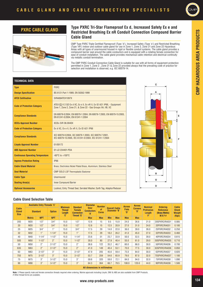
CMPHA
ZARD
OUSAR
EAPR
ODUC
TS
CMPC A B L E G L A N D A N D C A B L E C O N N E C T I O N S P E C I A L I S T S
134www.cmp-products.com
TECHNICAL DATA
Type PXRC
Design Specification BS 6121:Part 1:1989, EN 50262:1999
ATEX Cetification SIRA06ATEX1097X
Code of Protection Category ATEX II 2 GD Ex d IIC, Ex e II, Ex nR II, Ex tD A21 IP66, - EquipmentZone 1, Zone 2, Zone 21, & Zone 22 - Gas Groups IIA, IIB, IIC
Compliance Standards EN 60079-0:2004, EN 60079-1:2004, EN 60079-7:2003, EN 60079-15:2003,EN 61241-0:2004, EN 61241-1:2004
IECEx Approval Number IECEx SIR 06.0040X
Code of Protection Category Ex d IIC, Ex e II, Ex nR II, Ex tD A21 IP66
Compliance Standards IEC 60079-0:2004, IEC 60079-1:2003, IEC 60079-7:2001,IEC 60079-15:2005, IEC 61241-0:2004, IEC 61241-1:2004
Lloyds Approval Number 01/00172
ABS Approval Number 01-LD 234401-PDA
Continuous Operating Temperature -60°C to +100°C
Ingress Protection Rating IP66
Cable Gland Material Brass, Electroless Nickel Plated Brass, Aluminium, Stainless Steel
Seal Material CMP SOLO LSF Thermoplastic Elastomer
Cable Type Unarmoured
Sealing Area(s) Inner Compound Barrier
Optional Accessories Locknut, Entry Thread Seal, Serrated Washer, Earth Tag, Adaptor/Reducer
CMP Type PXRC Triple Certified Flameproof (Type 'd'), Increased Safety (Type 'e') and Restricted Breathing(Type ‘nR’) indoor and outdoor cable gland for use in Zone 1, Zone 2, Zone 21 and Zone 22 HazardousAreas with all types of unarmoured housed in rigid or flexible conduit systems. The cable gland provides acompound barrier seal around the cable conductors and is equipped with a rotating female connection forease of conduit installation. The cable gland provides mechanical cable retention and electrical continuityvia metallic conduit termination.
The CMP PXRC Conduit Connection Cable Gland is suitable for use with all forms of equipment protectionpermitted in Zone 1, Zone 2 , Zone 21 & Zone 22 provided always that the prevailing code of practice forselection and installation is observed, e.g. IEC 60079-14.
Type PXRC Tri-Star Flameproof Ex d, Increased Safety Ex e andRestricted Breathing Ex nR Conduit Connection Compound BarrierCable Gland
PXRC CABLE GLAND
BB
GG
DD
AA
CC
EE
FF
Cable Gland Selection Table
Note: † Please specify male and female connection threads required when ordering. Marine approvals including Lloyds, DNV & ABS are also available from CMP Products.# Other thread forms are available.
CableGlandSize
Available Entry Threads ‘C’MinimumThreadLength‘E’
StandardFemale
ConnectionThread ‘G’
DiameterOver
Conductors‘A’
Numberof
Cores
Overall CableDiameter ‘B’
AcrossFlats‘D’
AcrossCorners
‘D’
NominalProtrusionLength‘F’
OrderingReference
(BrassMetric)M X F #
CableGlandWeight(Kgs)
Standard Option
Metric NPT NPT Max Max Min Max Max Max
20S M20 1/2” 3/4” 15.0 1/2” 12.6 15 9.5 15.9 24.0 26.6 21.0 20SPXRCIRA031 0.085
20 M20 1/2” 3/4” 15.0 1/2” 12.6 15 12.5 20.9 27.0 31.0 24.0 20PXRCIRA031 0.100
25 M25 3/4” 1” 15.0 3/4” 17.5 29 14.0 22.0 36.0 39.0 26.0 25PXRCIRA032 0.250
32 M32 1” 1-1/4” 15.0 1” 17.5 29 18.2 26.2 41.0 45.0 27.0 32PXRCIRA033 0.460
40 M40 1-1/4” 1-1/2” 15.0 1-1/4” 23.6 51 23.7 33.9 50.0 53.5 28.0 40PXRCIRA034 0.615
50S M50 1-1/2” 2” 15.0 1-1/2” 30.0 80 27.9 40.4 55.0 61.0 29.0 50SPXRCIRA035 0.710
50 M50 2” 2-1/2” 15.0 2” 36.6 122 35.2 46.7 60.0 66.0 30.0 50PXRCIRA036 0.700
63S M63 2” 2-1/2” 15.0 2” 41.0 149 40.4 53.1 70.0 77.5 30.0 63SPXRCIRA036 0.850
63 M63 2-1/2” 3” 15.0 2-1/2” 47.9 205 45.6 59.4 75.0 84.0 30.0 63PXRCIRA037 0.820
75S M75 2-1/2” 3” 15.0 2-1/2” 53.7 259 54.6 65.9 79.0 87.0 32.0 75SPXRCIRA037 1.100
75 M75 3” 3-1/2” 15.0 3” 59.8 320 59.0 72.1 84.0 94.0 32.0 75PXRCIRA038 1.090
90 M90 3” 3-1/2” 15.0 3” 64.3 364 66.7 78.5 108.0 120.0 44.0 90PXRCIRA038 1.500
All dimensions in millimetres

MININGRANGE
MIN
INGRA
NGE
CMP C A B L E G L A N D A N D C A B L E C O N N E C T I O N S P E C I A L I S T S
135
CMP have an in-depth knowledge of not onlycable gland design, cable gland standards butalso an equal in-depth knowledge of thevarious environments and industries in whichour glands are to be installed. This knowledgegives CMP a distinct advantage in assistingpotential customers to resolve queries andprovide solutions to problems irrespective ofthe location be it Industrial, Surface HazardousGroup II or Underground Mining Group I.
The gland range offered accomodates all formsof cable used in mining locations. Unarmoured,single wire armoured and pliable wire armourmanufactured in both standard and specialmaterials to meet any application requirement.
The Group I Certified range of cable glandsprovide both the installer and OEM with thechoice of using either a threaded entry cable
gland or a flange mounted version both beingsuitable for direct entry into the equipment.Where a threaded entry is provided in theequipment and a flanged mounted gland eitheralready exists or is preferred or vice versa thenwe can supply a suitable adaptor which willconvert from a threaded entry to a flangedentry by use of a MA/TF adaptor oralternatively a MA/FT when a threaded entry ispreferred or required over a flange mountedentry.
For installations using non-filled cables orwhere the internal free volume exceeds 2 litresbarrier type cable glands are available andprovide a compound barrier seal around theconductors and an environmental seal on thecable outer sheath. Again these are availablefor all cable types and can be supplied witheither a threaded or flanged entry.
APPLICATION
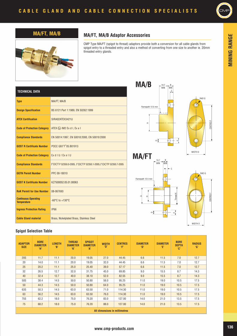
MIN
INGRA
NGE
136
C A B L E G L A N D A N D C A B L E C O N N E C T I O N S P E C I A L I S T S CMP
TECHNICAL DATA
Type MA/FT, MA/B
Design Specification BS 6121:Part 1:1989, EN 50262:1999
ATEX Certification SIRA02ATEX3421U
Code of Protection Category ATEX IM2 Ex d I, Ex e I
Compliance Standards EN 50014:1997, EN 50018:2000, EN 50019:2000
GOST R Certificate Number POCC GB. 05.B01913
Code of Protection Category Ex d I U / Ex e I U
Compliance Standards P 52350.0-2005, P 52350.1-2005, P 52350.7-2005
GGTN Permit Number PPC 00-18010
GOST K Certificate Number KZ7500052.05.01.00063
RoK Permit for Use Number 08-067693
Continuous OperatingTemperature -60°C to +130°C
Ingress Protection Rating IP66
Cable Gland material Brass, Nickelplated Brass, Stainless Steel
CMP Type MA/FT (spigot to thread) adaptors provide both a conversion for all cable glands fromspigot entry to a threaded entry and also a method of converting from one size to another ie. 20mmthreaded entry glands.
ADAPTORSIZE
BOREDIAMETER
‘H’
LENGTH‘B’
THREADDIAMETER
‘K’
SPIGOTDIAMETER
‘A’
WIDTH‘O’
CENTRES‘F’
DIAMETER‘D’
DIAMETER‘E’
BOREDEPTH‘C’
RADIUS‘G’
20S 11.7 11.1 20.0 19.05 27.0 44.45 6.6 11.5 7.0 12.7
20 14.0 11.1 20.0 19.05 32.0 44.45 6.6 11.5 7.0 12.7
25 20.2 11.1 25.0 25.40 39.0 57.17 6.6 11.5 7.0 12.7
32 26.5 12.7 32.0 31.75 45.0 69.85 9.0 15.5 8.7 14.3
40 32.4 12.7 40.0 38.10 52.0 82.55 9.0 15.5 8.7 14.3
50S 38.4 14.5 50.0 50.80 58.0 95.25 11.0 19.0 10.5 17.5
50 44.3 14.5 50.0 50.80 64.0 95.25 11.0 19.0 10.5 17.5
63S 50.3 14.5 63.0 63.50 71.0 114.30 11.0 19.0 10.5 17.5
63 56.2 14.5 63.0 63.50 76.0 114.30 11.0 19.0 10.5 17.5
75S 62.2 18.0 75.0 76.20 83.0 127.00 14.0 21.0 13.5 17.5
75 68.2 18.0 75.0 76.20 88.0 127.00 14.0 21.0 13.5 17.5
All dimensions in millimetres
MA/FT, MA/B Adaptor AccessoriesMA/FT, MA/B
Flamepath 12.5 min
14.7 B
C
MIN MIN
Thre
adK
ED
D
HA
CENT
RES
F
WIDTH 0
14.7 BMIN MIN
C
Flamepath 12.5 min
A
E
CENT
RES
F
WIDTH 0
RAD G
RAD G
MA/B
MA/FT
Spigot Selection Table
LLU
OCTL
OCTL
OCTL
www.cmp-products.com
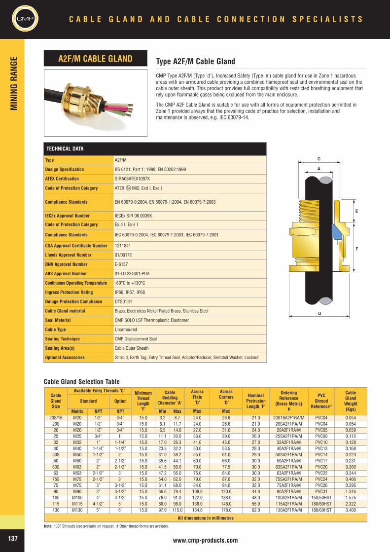
CMPMIN
INGRA
NGE
C A B L E G L A N D A N D C A B L E C O N N E C T I O N S P E C I A L I S T S
137 www.cmp-products.com
Note: *LSF Shrouds also available on request. # Other thread forms are available.
TECHNICAL DATA
Type A2F/M
Design Specification BS 6121: Part 1: 1989, EN 50262:1999
ATEX Certification SIRA06ATEX1097X
Code of Protection Category ATEX IM2, Exd I, Exe I
Compliance Standards EN 60079-0:2004, EN 60079-1:2004, EN 60079-7:2003
IECEx Approval Number IECEx SIR 06.0039X
Code of Protection Category Ex d I, Ex e I
Compliance Standards IEC 60079-0:2004, IEC 60079-1:2003, IEC 60079-7:2001
CSA Approval Certificate Number 1211841
Lloyds Approval Number 01/00172
DNV Approval Number E-6157
ABS Approval Number 01-LD 234401-PDA
Continuous Operating Temperature -60°C to +130°C
Ingress Protection Rating IP66, IP67, IP68
Deluge Protection Compliance DTS01:91
Cable Gland material Brass, Electroless Nickel Plated Brass, Stainless Steel
Seal Material CMP SOLO LSF Thermoplastic Elastomer
Cable Type Unarmoured
Sealing Technique CMP Displacement Seal
Sealing Area(s) Cable Outer Sheath
Optional Accessories Shroud, Earth Tag, Entry Thread Seal, Adaptor/Reducer, Serrated Washer, Locknut
CMP Type A2F/M (Type 'd'), Increased Safety (Type 'e') cable gland for use in Zone 1 hazardousareas with un-armoured cable providing a combined flameproof seal and environmental seal on thecable outer sheath. This product provides full compatibility with restricted breathing equipment thatrely upon flammable gases being excluded from the main enclosure.
The CMP A2F Cable Gland is suitable for use with all forms of equipment protection permitted inZone 1 provided always that the prevailing code of practice for selection, installation andmaintenance is observed, e.g. IEC 60079-14.
CableGlandSize
Available Entry Threads ‘C’ MinimumThreadLength‘E’
CableBedding
Diameter ‘A’
AcrossFlats‘D’
AcrossCorners
‘D’NominalProtrusionLength ‘F’
OrderingReference
(Brass Metric)#
PVCShroud
Reference*
CableGlandWeight(Kgs)
Standard Option
Metric NPT NPT Min Max20S/16 M20 1/2” 3/4” 15.0 3.2 8.7 24.0 26.6 21.0 20S16A2F1RA/M PVC04 0.05420S M20 1/2” 3/4” 15.0 6.1 11.7 24.0 26.6 21.0 20SA2F1RA/M PVC04 0.05420 M20 1/2” 3/4” 15.0 6.5 14.0 27.0 31.0 24.0 20A2F1RA/M PVC05 0.05925 M25 3/4” 1” 15.0 11.1 20.0 36.0 39.0 26.0 25SA2F1RA/M PVC09 0.11232 M32 1” 1-1/4” 15.0 17.0 26.3 41.0 45.0 27.0 32A2F1RA/M PVC10 0.12840 M40 1-1/4” 1-1/2” 15.0 23.5 32.2 50.0 53.5 28.0 40A2F1RA/M PVC13 0.16850S M50 1-1/2” 2” 15.0 31.0 38.2 55.0 61.0 29.0 50SA2F1RA/M PVC14 0.22450 M50 2” 2-1/2” 15.0 35.6 44.1 60.0 66.0 30.0 50A2F1RA/M PVC17 0.23163S M63 2” 2-1/2” 15.0 41.5 50.0 70.0 77.5 30.0 63SA2F1RA/M PVC20 0.36063 M63 2-1/2” 3” 15.0 47.2 56.0 75.0 84.0 30.0 63A2F1RA/M PVC22 0.34475S M75 2-1/2” 3” 15.0 54.0 62.0 79.0 87.0 32.0 75SA2F1RA/M PVC24 0.46675 M75 3” 3-1/2” 15.0 61.1 68.0 84.0 94.0 32.0 75A2F1RA/M PVC26 0.39590 M90 3” 3-1/2” 15.0 66.6 79.4 108.0 120.0 44.0 90A2F1RA/M PVC31 1.346100 M100 4” 4-1/2” 15.0 76.0 91.0 122.0 138.0 48.0 100A2F1RA/M 150/50HST 1.575115 M115 4-1/2” 5” 15.0 86.0 98.0 138.0 148.0 55.0 115A2F1RA/M 180/60HST 2.322130 M130 5” 6” 15.0 97.0 115.0 154.0 178.0 62.0 130A2F1RA/M 180/60HST 3.400
All dimensions in millimetres
Type A2F/M Cable GlandA2F/M CABLE GLAND
DD
AA
CC
EE
FF
Cable Gland Selection Table
Max Max
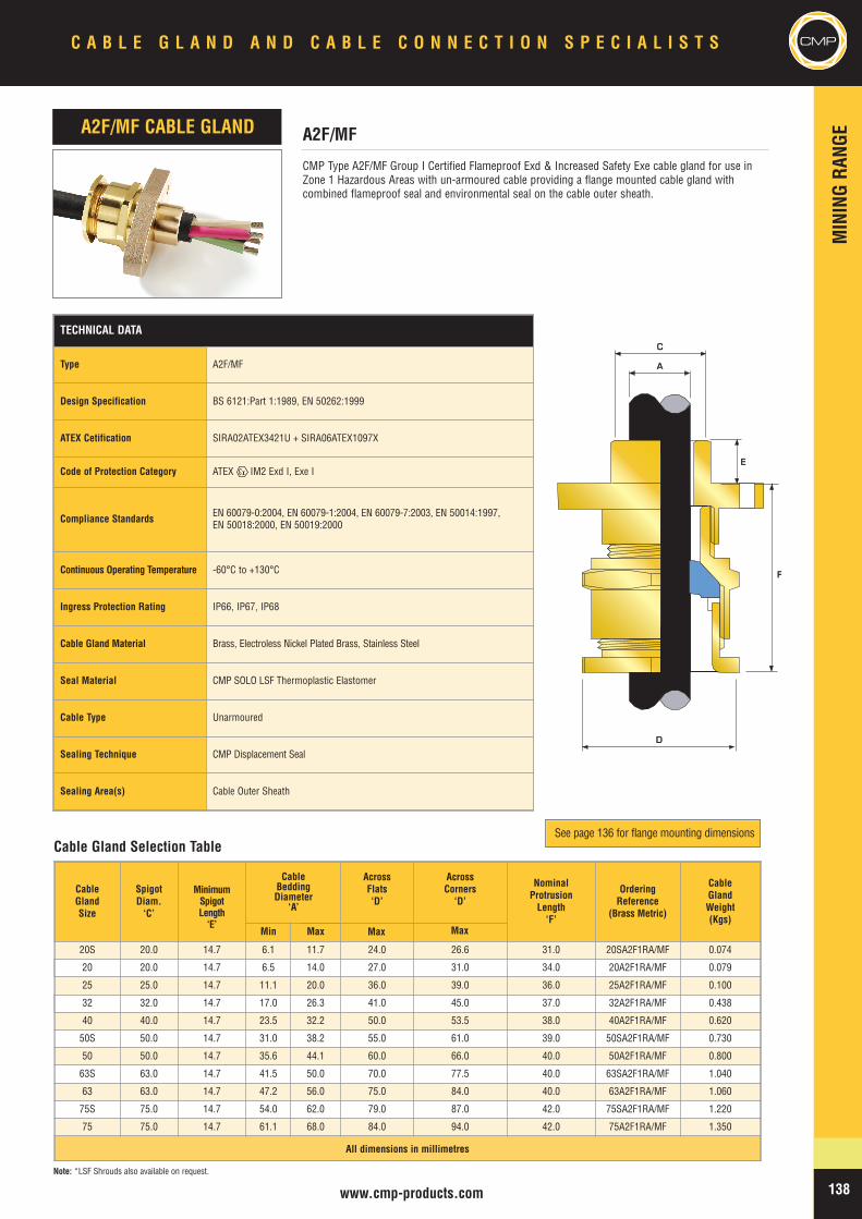
MIN
INGRA
NGE
CMPC A B L E G L A N D A N D C A B L E C O N N E C T I O N S P E C I A L I S T S
138www.cmp-products.com
TECHNICAL DATA
Type A2F/MF
Design Specification BS 6121:Part 1:1989, EN 50262:1999
ATEX Cetification SIRA02ATEX3421U + SIRA06ATEX1097X
Code of Protection Category ATEX IM2 Exd I, Exe I
Compliance Standards EN 60079-0:2004, EN 60079-1:2004, EN 60079-7:2003, EN 50014:1997,EN 50018:2000, EN 50019:2000
Continuous Operating Temperature -60°C to +130°C
Ingress Protection Rating IP66, IP67, IP68
Cable Gland Material Brass, Electroless Nickel Plated Brass, Stainless Steel
Seal Material CMP SOLO LSF Thermoplastic Elastomer
Cable Type Unarmoured
Sealing Technique CMP Displacement Seal
Sealing Area(s) Cable Outer Sheath
CMP Type A2F/MF Group I Certified Flameproof Exd & Increased Safety Exe cable gland for use inZone 1 Hazardous Areas with un-armoured cable providing a flange mounted cable gland withcombined flameproof seal and environmental seal on the cable outer sheath.
A2F/MFA2F/MF CABLE GLAND
DD
AA
CC
EE
FF
Note: *LSF Shrouds also available on request.
Cable Gland Selection Table
CableGlandSize
SpigotDiam.‘C’
MinimumSpigotLength‘E’
CableBeddingDiameter
‘A’
AcrossFlats‘D’
AcrossCorners
‘D’
NominalProtrusionLength‘F’
OrderingReference
(Brass Metric)
CableGlandWeight(Kgs)
Min Max
20S 20.0 14.7 6.1 11.7 24.0 26.6 31.0 20SA2F1RA/MF 0.074
20 20.0 14.7 6.5 14.0 27.0 31.0 34.0 20A2F1RA/MF 0.079
25 25.0 14.7 11.1 20.0 36.0 39.0 36.0 25A2F1RA/MF 0.100
32 32.0 14.7 17.0 26.3 41.0 45.0 37.0 32A2F1RA/MF 0.438
40 40.0 14.7 23.5 32.2 50.0 53.5 38.0 40A2F1RA/MF 0.620
50S 50.0 14.7 31.0 38.2 55.0 61.0 39.0 50SA2F1RA/MF 0.730
50 50.0 14.7 35.6 44.1 60.0 66.0 40.0 50A2F1RA/MF 0.800
63S 63.0 14.7 41.5 50.0 70.0 77.5 40.0 63SA2F1RA/MF 1.040
63 63.0 14.7 47.2 56.0 75.0 84.0 40.0 63A2F1RA/MF 1.060
75S 75.0 14.7 54.0 62.0 79.0 87.0 42.0 75SA2F1RA/MF 1.220
75 75.0 14.7 61.1 68.0 84.0 94.0 42.0 75A2F1RA/MF 1.350
All dimensions in millimetres
See page 136 for flange mounting dimensions
Max Max
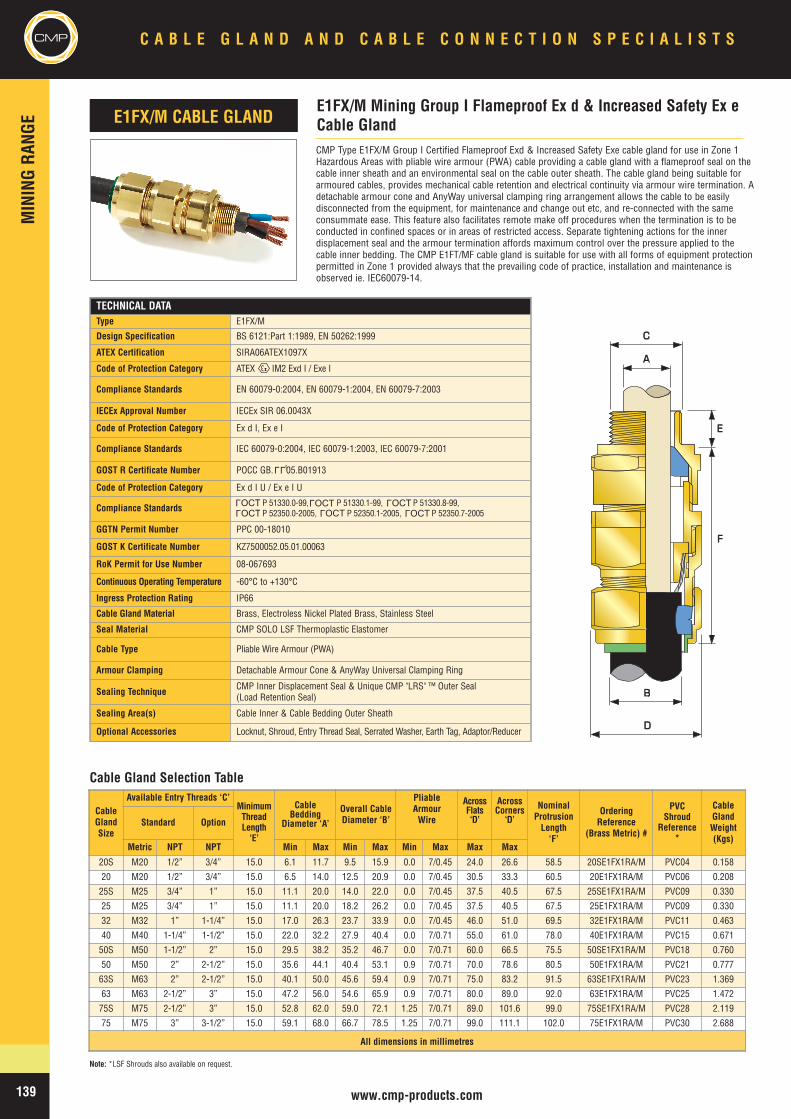
CMPMIN
INGRA
NGE
C A B L E G L A N D A N D C A B L E C O N N E C T I O N S P E C I A L I S T S
139 www.cmp-products.com
TECHNICAL DATAType E1FX/M
Design Specification BS 6121:Part 1:1989, EN 50262:1999
ATEX Certification SIRA06ATEX1097X
Code of Protection Category ATEX IM2 Exd I / Exe I
Compliance Standards EN 60079-0:2004, EN 60079-1:2004, EN 60079-7:2003
IECEx Approval Number IECEx SIR 06.0043X
Code of Protection Category Ex d I, Ex e I
Compliance Standards IEC 60079-0:2004, IEC 60079-1:2003, IEC 60079-7:2001
GOST R Certificate Number POCC GB. 05.B01913
Code of Protection Category Ex d I U / Ex e I U
Compliance Standards P 51330.0-99, P 51330.1-99, P 51330.8-99,P 52350.0-2005, P 52350.1-2005, P 52350.7-2005
GGTN Permit Number PPC 00-18010
GOST K Certificate Number KZ7500052.05.01.00063
RoK Permit for Use Number 08-067693
Continuous Operating Temperature -60°C to +130°C
Ingress Protection Rating IP66
Cable Gland Material Brass, Electroless Nickel Plated Brass, Stainless Steel
Seal Material CMP SOLO LSF Thermoplastic Elastomer
Cable Type Pliable Wire Armour (PWA)
Armour Clamping Detachable Armour Cone & AnyWay Universal Clamping Ring
Sealing Technique CMP Inner Displacement Seal & Unique CMP "LRS" ™ Outer Seal(Load Retention Seal)
Sealing Area(s) Cable Inner & Cable Bedding Outer Sheath
Optional Accessories Locknut, Shroud, Entry Thread Seal, Serrated Washer, Earth Tag, Adaptor/Reducer
CMP Type E1FX/M Group I Certified Flameproof Exd & Increased Safety Exe cable gland for use in Zone 1Hazardous Areas with pliable wire armour (PWA) cable providing a cable gland with a flameproof seal on thecable inner sheath and an environmental seal on the cable outer sheath. The cable gland being suitable forarmoured cables, provides mechanical cable retention and electrical continuity via armour wire termination. Adetachable armour cone and AnyWay universal clamping ring arrangement allows the cable to be easilydisconnected from the equipment, for maintenance and change out etc, and re-connected with the sameconsummate ease. This feature also facilitates remote make off procedures when the termination is to beconducted in confined spaces or in areas of restricted access. Separate tightening actions for the innerdisplacement seal and the armour termination affords maximum control over the pressure applied to thecable inner bedding. The CMP E1FT/MF cable gland is suitable for use with all forms of equipment protectionpermitted in Zone 1 provided always that the prevailing code of practice, installation and maintenance isobserved ie. IEC60079-14.
E1FX/M Mining Group I Flameproof Ex d & Increased Safety Ex eCable GlandE1FX/M CABLE GLAND
AA
BB
DD
CC
EE
FF
Cable Gland Selection Table
Note: *LSF Shrouds also available on request.
LLU
OCTL
OCTL OCT
LOCT
L
OCTL
OCTL
CableGlandSize
Available Entry Threads ‘C’MinimumThreadLength‘E’
CableBedding
Diameter ‘A’
Overall CableDiameter ‘B’
PliableArmourWire
AcrossFlats‘D’
AcrossCorners
‘D’NominalProtrusionLength‘F’
OrderingReference
(Brass Metric) #
PVCShroud
Reference*
CableGlandWeight(Kgs)
Standard Option
Metric NPT NPT Min Max Min Max Min Max Max Max
20S M20 1/2” 3/4” 15.0 6.1 11.7 9.5 15.9 0.0 7/0.45 24.0 26.6 58.5 20SE1FX1RA/M PVC04 0.158
20 M20 1/2” 3/4” 15.0 6.5 14.0 12.5 20.9 0.0 7/0.45 30.5 33.3 60.5 20E1FX1RA/M PVC06 0.208
25S M25 3/4” 1” 15.0 11.1 20.0 14.0 22.0 0.0 7/0.45 37.5 40.5 67.5 25SE1FX1RA/M PVC09 0.330
25 M25 3/4” 1” 15.0 11.1 20.0 18.2 26.2 0.0 7/0.45 37.5 40.5 67.5 25E1FX1RA/M PVC09 0.330
32 M32 1” 1-1/4” 15.0 17.0 26.3 23.7 33.9 0.0 7/0.45 46.0 51.0 69.5 32E1FX1RA/M PVC11 0.463
40 M40 1-1/4” 1-1/2” 15.0 22.0 32.2 27.9 40.4 0.0 7/0.71 55.0 61.0 78.0 40E1FX1RA/M PVC15 0.671
50S M50 1-1/2” 2” 15.0 29.5 38.2 35.2 46.7 0.0 7/0.71 60.0 66.5 75.5 50SE1FX1RA/M PVC18 0.760
50 M50 2” 2-1/2” 15.0 35.6 44.1 40.4 53.1 0.9 7/0.71 70.0 78.6 80.5 50E1FX1RA/M PVC21 0.777
63S M63 2” 2-1/2” 15.0 40.1 50.0 45.6 59.4 0.9 7/0.71 75.0 83.2 91.5 63SE1FX1RA/M PVC23 1.369
63 M63 2-1/2” 3” 15.0 47.2 56.0 54.6 65.9 0.9 7/0.71 80.0 89.0 92.0 63E1FX1RA/M PVC25 1.472
75S M75 2-1/2” 3” 15.0 52.8 62.0 59.0 72.1 1.25 7/0.71 89.0 101.6 99.0 75SE1FX1RA/M PVC28 2.119
75 M75 3” 3-1/2” 15.0 59.1 68.0 66.7 78.5 1.25 7/0.71 99.0 111.1 102.0 75E1FX1RA/M PVC30 2.688
All dimensions in millimetres
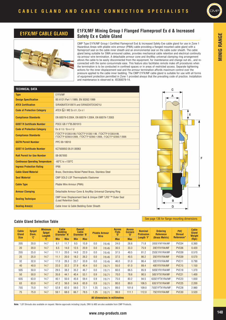
MIN
IGRA
NGE
140www.cmp-products.com
CableGlandSize
SpigotDiam.‘C’
MinimumSpigotLenghth
‘E’
CableBedding
Diameter ‘A’
OverallCable
Diameter ‘B’ Pliable ArmourWire
AcrossFlats‘D’
AcrossCorners
‘D’NominalProtrusionLength ‘F’
OrderingReference
(Brass Metric)
PVCShroud
Reference*
CableGlandWeight(Kgs)Min Max Min Max
20S 20.0 14.7 6.1 11.7 9.5 15.9 0.0 7/0.45 24.0 26.6 71.8 20SE1FXF1RA/MF PVC04 0.360
20 20.0 14.7 6.5 14.0 12.5 20.9 0.0 7/0.45 30.5 33.3 75.9 20E1FX1RA/MF PVC06 0.420
25S 25.0 14.7 11.1 20.0 14.0 22.0 0.0 7/0.45 37.5 40.5 81.2 25SE1FX1RA/MF PVC09 0.570
25 25.0 14.7 11.1 20.0 18.2 26.2 0.0 7/0.45 37.5 40.5 86.2 25E1FX1RA/MF PVC09 0.570
32 32.0 14.7 17.0 26.3 23.7 33.9 0.0 7/0.45 46.0 51.0 86.4 32E1FX1RA/MF PVC11 0.790
40 40.0 14.7 22.0 32.2 27.9 40.4 0.0 7/0.71 55.0 61.0 89.4 40E1FX1RA/MF PVC15 1.150
50S 50.0 14.7 29.5 38.2 35.2 46.7 0.0 7/0.71 60.0 66.5 85.9 50SE1FX1RA/MF PVC18 1.370
50 50.0 14.7 35.6 44.1 40.4 53.1 0.9 7/0.71 70.0 78.6 90.5 50E1FTX1RA/MF PVC21 1.400
63S 63.0 14.7 40.1 50.0 45.6 59.4 0.9 7/0.71 75.0 83.2 94.5 63SE1FTX1RA/MF PVC23 1.830
63 63.0 14.7 47.2 56.0 54.6 65.9 0.9 7/0.71 80.0 89.0 106.5 63E1FTX1RA/MF PVC25 2.200
75S 75.0 14.7 52.8 62.0 59.0 72.1 1.25 7/0.71 89.0 101.6 109.0 75SE1FTX1RA/MF PVC28 2.980
75 75.0 14.7 59.1 68.0 66.7 78.5 1.25 7/0.71 99.0 111.1 112.0 75E1FX1RA/MF PVC30 3.520
All dimensions in millimetres
TECHNICAL DATA
Type E1FX/MF
Design Specification BS 6121:Part 1:1989, EN 50262:1999
ATEX Certification SIRA06ATEX1097X and SIRA02ATEX3421U
Code of Protection Category ATEX I M2 Ex d I, Ex e I
Compliance Standards EN 60079-0:2004, EN 60079-1:2004, EN 60079-7:2003
GOST R Certificate Number POCC GB. 05.B01913
Code of Protection Category Ex d I U / Ex e I U
Compliance Standards P 51330.0-99, P 51330.1-99, P 51330.8-99,P 52350.0-2005, P 52350.1-2005, P 52350.7-2005
GGTN Permit Number PPC 00-18010
GOST K Certificate Number KZ7500052.05.01.00063
RoK Permit for Use Number 08-067693
Continuous Operating Temperature -60°C to +130°C
Ingress Protection Rating IP66
Cable Gland Material Brass, Electroless Nickel Plated Brass, Stainless Steel
Seal Material CMP SOLO LSF Thermoplastic Elastomer
Cable Type Pliable Wire Armour (PWA)
Armour Clamping Detachable Armour Cone & AnyWay Universal Clamping Ring
Sealing Technique CMP Inner Displacement Seal & Unique CMP "LRS" ™ Outer Seal(Load Retention Seal)
Sealing Area(s) Cable Inner & Cable Bedding Outer Sheath
CMP Type E1FX/MF Group I Certified Flameproof Exd & Increased Safety Exe cable gland for use in Zone 1Hazardous Areas with pliable wire armour (PWA) cable providing a flanged mounted cable gland with aflameproof seal on the cable inner sheath and an environmental seal on the cable outer sheath. The cablegland being suitable for SWA armoured cables, provides mechanical cable retention and electrical continuityvia armour wire termination. A detachable armour cone and AnyWay universal clamping ring arrangementallows the cable to be easily disconnected from the equipment, for maintenance and change out etc., and re-connected with the same consummate ease. This feature also facilitates remote make off procedures whenthe termination is to be conducted in confined spaces or in areas of restricted access. Separate tighteningactions for the inner displacement seal and the armour termination affords maximum control over thepressure applied to the cable inner bedding. The CMP E1FX/MF cable gland is suitable for use with all formsof equipment protection permitted in Zone 1 provided always that the prevailing code of practice. Installationand maintenance is observed ie. IEC60079-14.
E1FX/MF Mining Group I Flanged Flameproof Ex d & IncreasedSafety Ex e Cable GlandE1FX/MF CABLE GLAND
AA
BB
DD
CC
FF
EE
Note: *LSF Shrouds also available on request. Marine approvals including Lloyds, DNV & ABS are also available from CMP Products.
Cable Gland Selection TableSee page 136 for flange mounting dimensions
LLU
OCTL
OCTL OCT
LOCT
L
OCTL
OCTL
Max Max
C A B L E G L A N D A N D C A B L E C O N N E C T I O N S P E C I A L I S T S CMP
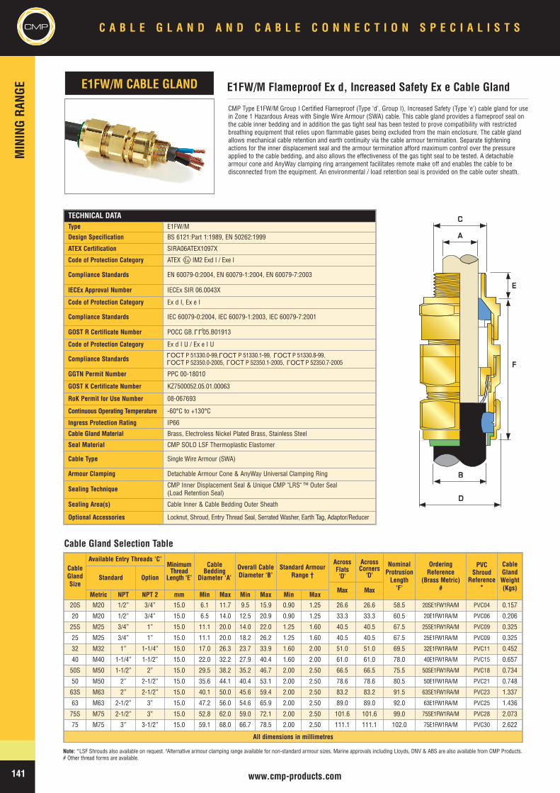
CMPMIN
INGRA
NGE
C A B L E G L A N D A N D C A B L E C O N N E C T I O N S P E C I A L I S T S
141 www.cmp-products.com
Note: *LSF Shrouds also available on request. †Alternative armour clamping range available for non-standard armour sizes. Marine approvals including Lloyds, DNV & ABS are also available from CMP Products.# Other thread forms are available.
CMP Type E1FW/M Group I Certified Flameproof (Type ‘d’, Group I), Increased Safety (Type ‘e’) cable gland for usein Zone 1 Hazardous Areas with Single Wire Armour (SWA) cable. This cable gland provides a flameproof seal onthe cable inner bedding and in addition the gas tight seal has been tested to prove compatibility with restrictedbreathing equipment that relies upon flammable gases being excluded from the main enclosure. The cable glandallows mechanical cable retention and earth continuity via the cable armour termination. Separate tighteningactions for the inner displacement seal and the armour termination afford maximum control over the pressureapplied to the cable bedding, and also allows the effectiveness of the gas tight seal to be tested. A detachablearmour cone and AnyWay clamping ring arrangement facilitates remote make off and enables the cable to bedisconnected from the equipment. An environmental / load retention seal is provided on the cable outer sheath.
CableGlandSize
Available Entry Threads ‘C’MinimumThread
Length ‘E’
CableBedding
Diameter ‘A’
Overall CableDiameter ‘B’
Standard ArmourRange †
AcrossFlats‘D’
Max
AcrossCorners
‘D’
Max
NominalProtrusionLength’F’
OrderingReference
(Brass Metric)#
PVCShroud
Reference*
CableGlandWeight(Kgs)
Standard Option
Metric NPT NPT 2 mm Min Max Min Max Min Max
20S M20 1/2” 3/4” 15.0 6.1 11.7 9.5 15.9 0.90 1.25 26.6 26.6 58.5 20SE1FW1RA/M PVC04 0.157
20 M20 1/2” 3/4” 15.0 6.5 14.0 12.5 20.9 0.90 1.25 33.3 33.3 60.5 20E1FW1RA/M PVC06 0.206
25S M25 3/4” 1” 15.0 11.1 20.0 14.0 22.0 1.25 1.60 40.5 40.5 67.5 25SE1FW1RA/M PVC09 0.325
25 M25 3/4” 1” 15.0 11.1 20.0 18.2 26.2 1.25 1.60 40.5 40.5 67.5 25E1FW1RA/M PVC09 0.325
32 M32 1” 1-1/4” 15.0 17.0 26.3 23.7 33.9 1.60 2.00 51.0 51.0 69.5 32E1FW1RA/M PVC11 0.452
40 M40 1-1/4” 1-1/2” 15.0 22.0 32.2 27.9 40.4 1.60 2.00 61.0 61.0 78.0 40E1FW1RA/M PVC15 0.657
50S M50 1-1/2” 2” 15.0 29.5 38.2 35.2 46.7 2.00 2.50 66.5 66.5 75.5 50SE1FW1RA/M PVC18 0.734
50 M50 2” 2-1/2” 15.0 35.6 44.1 40.4 53.1 2.00 2.50 78.6 78.6 80.5 50E1FW1RA/M PVC21 0.748
63S M63 2” 2-1/2” 15.0 40.1 50.0 45.6 59.4 2.00 2.50 83.2 83.2 91.5 63SE1FW1RA/M PVC23 1.337
63 M63 2-1/2” 3” 15.0 47.2 56.0 54.6 65.9 2.00 2.50 89.0 89.0 92.0 63E1FW1RA/M PVC25 1.436
75S M75 2-1/2” 3” 15.0 52.8 62.0 59.0 72.1 2.00 2.50 101.6 101.6 99.0 75SE1FW1RA/M PVC28 2.073
75 M75 3” 3-1/2” 15.0 59.1 68.0 66.7 78.5 2.00 2.50 111.1 111.1 102.0 75E1FW1RA/M PVC30 2.622
All dimensions in millimetres
E1FW/M Flameproof Ex d, Increased Safety Ex e Cable GlandE1FW/M CABLE GLAND
AA
BB
DD
CC
EE
FF
Cable Gland Selection Table
TECHNICAL DATAType E1FW/M
Design Specification BS 6121:Part 1:1989, EN 50262:1999
ATEX Certification SIRA06ATEX1097X
Code of Protection Category ATEX IM2 Exd I / Exe I
Compliance Standards EN 60079-0:2004, EN 60079-1:2004, EN 60079-7:2003
IECEx Approval Number IECEx SIR 06.0043X
Code of Protection Category Ex d I, Ex e I
Compliance Standards IEC 60079-0:2004, IEC 60079-1:2003, IEC 60079-7:2001
GOST R Certificate Number POCC GB. 05.B01913
Code of Protection Category Ex d I U / Ex e I U
Compliance Standards P 51330.0-99, P 51330.1-99, P 51330.8-99,P 52350.0-2005, P 52350.1-2005, P 52350.7-2005
GGTN Permit Number PPC 00-18010
GOST K Certificate Number KZ7500052.05.01.00063
RoK Permit for Use Number 08-067693
Continuous Operating Temperature -60°C to +130°C
Ingress Protection Rating IP66
Cable Gland Material Brass, Electroless Nickel Plated Brass, Stainless Steel
Seal Material CMP SOLO LSF Thermoplastic Elastomer
Cable Type Single Wire Armour (SWA)
Armour Clamping Detachable Armour Cone & AnyWay Universal Clamping Ring
Sealing Technique CMP Inner Displacement Seal & Unique CMP "LRS" ™ Outer Seal(Load Retention Seal)
Sealing Area(s) Cable Inner & Cable Bedding Outer Sheath
Optional Accessories Locknut, Shroud, Entry Thread Seal, Serrated Washer, Earth Tag, Adaptor/Reducer
LLU
OCTL
OCTL OCT
LOCT
L
OCTL
OCTL
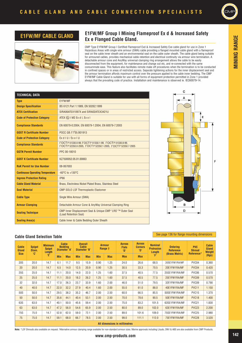
MIN
INGRA
NGE
CMPC A B L E G L A N D A N D C A B L E C O N N E C T I O N S P E C I A L I S T S
142www.cmp-products.com
CableGlandSize
SpigotDiam.‘C’
MinimumSpigotLength‘E’
CableBedding
Diameter ‘A’
OverallCable
Diameter ‘B’
ArmourRange †
AcrossFlats‘D’
AcrossCorners
‘D’
NominalProtrusionLength‘F’
OrderingReference
(Brass Metric)
PVCShroud
Reference*
CableGlandWeight(Kgs)Min Max Min Max Min Max
20S 20.0 14.7 6.1 11.7 9.5 15.9 0.90 1.25 24.0 26.6 68.5 20SE1FW1RA/MF PVC04 0.360
20 20.0 14.7 6.5 14.0 12.5 20.9 0.90 1.25 30.5 33.3 70.5 20E1FW1RA/MF PVC04 0.420
25S 25.0 14.7 11.1 20.0 14.0 22.0 1.25 1.60 37.5 40.5 77.5 25SE1FW1RA/MF PVC06 0.570
25 25.0 14.7 11.1 20.0 18.2 26.2 1.25 1.60 37.5 40.5 77.5 25E1FW1RA/MF PVC09 0.570
32 32.0 14.7 17.0 26.3 23.7 33.9 1.60 2.00 46.0 51.0 79.5 32E1FW1RA/MF PVC09 0.790
40 40.0 14.7 22.0 32.2 27.9 40.4 1.60 2.00 55.0 61.0 88.0 40E1FW1RA/MF PVC11 1.150
50S 50.0 14.7 29.5 38.2 35.2 46.7 2.00 2.50 60.0 66.5 85.5 50SE1FW1RA/MF PVC15 1.370
50 50.0 14.7 35.6 44.1 40.4 53.1 2.00 2.50 70.0 78.6 90.5 50E1FW1RA/MF PVC18 1.400
63S 63.0 14.7 40.1 50.0 45.6 59.4 2.00 2.50 75.0 83.2 101.5 63SE1FW1RA/MF PVC21 1.830
63 63.0 14.7 47.2 56.0 54.6 65.9 2.00 2.50 80.0 89.0 102.0 63E1FW1RA/MF PVC23 2.200
75S 75.0 14.7 52.8 62.0 59.0 72.1 2.00 2.50 89.0 101.6 109.0 75SE1FW1RA/MF PVC25 2.980
75 75.0 14.7 59.1 68.0 66.7 78.5 2.00 2.50 99.0 111.1 112.0 75E1FW1RA/MF PVC28 3.520
All dimensions in millimetres
CMP Type E1FW/MF Group I Certified Flameproof Exd & Increased Safety Exe cable gland for use in Zone 1Hazardous Areas with single wire armour (SWA) cable providing a flanged mounted cable gland with a flameproofseal on the cable inner sheath and an environmental seal on the cable outer sheath. The cable gland being suitablefor armoured cables, provides mechanical cable retention and electrical continuity via armour wire termination. Adetachable armour cone and AnyWay universal clamping ring arrangement allows the cable to be easilydisconnected from the equipment, for maintenance and change out etc, and re-connected with the sameconsummate ease. This feature also facilitates remote make off procedures when the termination is to be conductedin confined spaces or in areas of restricted access. Separate tightening actions for the inner displacement seal andthe armour termination affords maximum control over the pressure applied to the cable inner bedding. The CMPE1FW/MF Cable Gland is suitable for use with all forms of equipment protection permitted in Zone 1 providedalways that the prevailing code of practice. Installation and maintenance is observed ie. IEC60079-14.
E1FW/MF Group I Mining Flameproof Ex d & Increased SafetyEx e Flanged Cable Gland.
E1FW/MF CABLE GLAND
AA
BB
DD
CC
FF
EE
Cable Gland Selection Table
Note: *LSF Shrouds also available on request. †Alternative armour clamping range available for non-standard armour sizes. Marine approvals including Lloyds, DNV & ABS are also available from CMP Products.
See page 136 for flange mounting dimensions
TECHNICAL DATA
Type E1FW/MF
Design Specification BS 6121:Part 1:1989, EN 50262:1999
ATEX Certification SIRA06ATEX1097X and SIRA02ATEX3421U
Code of Protection Category ATEX I M2 Ex d I, Ex e I
Compliance Standards EN 60079-0:2004, EN 60079-1:2004, EN 60079-7:2003
GOST R Certificate Number POCC GB. 05.B01913
Code of Protection Category Ex d I U / Ex e I U
Compliance Standards P 51330.0-99, P 51330.1-99, P 51330.8-99,P 52350.0-2005, P 52350.1-2005, P 52350.7-2005
GGTN Permit Number PPC 00-18010
GOST K Certificate Number KZ7500052.05.01.00063
RoK Permit for Use Number 08-067693
Continuous Operating Temperature -60°C to +130°C
Ingress Protection Rating IP66
Cable Gland Material Brass, Electroless Nickel Plated Brass, Stainless Steel
Seal Material CMP SOLO LSF Thermoplastic Elastomer
Cable Type Single Wire Armour (SWA)
Armour Clamping Detachable Armour Cone & AnyWay Universal Clamping Ring
Sealing Technique CMP Inner Displacement Seal & Unique CMP "LRS" ™ Outer Seal(Load Retention Seal)
Sealing Area(s) Cable Inner & Cable Bedding Outer Sheath
LLU
OCTL
OCTL OCT
LOCT
L
OCTL
OCTL
Max Max
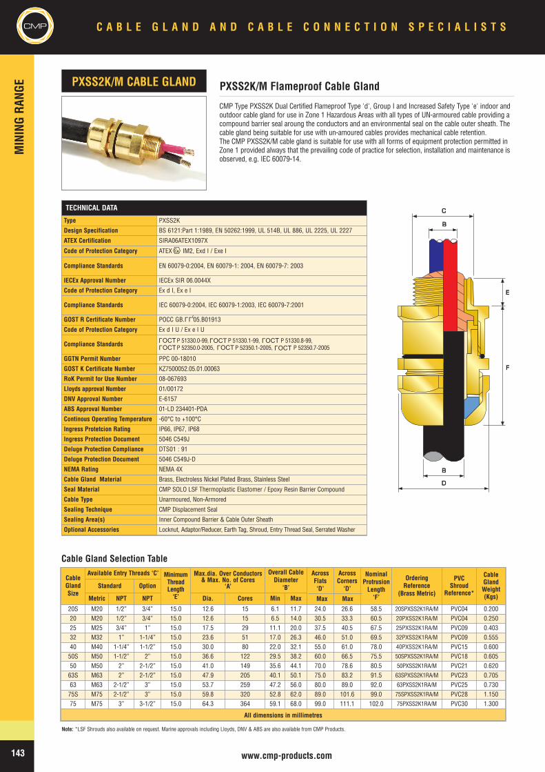
CMPMIN
INGRA
NGE
C A B L E G L A N D A N D C A B L E C O N N E C T I O N S P E C I A L I S T S
143 www.cmp-products.com
Note: *LSF Shrouds also available on request. Marine approvals including Lloyds, DNV & ABS are also available from CMP Products.
TECHNICAL DATA
Type PXSS2K
Design Specification BS 6121:Part 1:1989, EN 50262:1999, UL 514B, UL 886, UL 2225, UL 2227
ATEX Certification SIRA06ATEX1097X
Code of Protection Category ATEX IM2, Exd I / Exe I
Compliance Standards EN 60079-0:2004, EN 60079-1: 2004, EN 60079-7: 2003
IECEx Approval Number IECEx SIR 06.0044X
Code of Protection Category Ex d I, Ex e I
Compliance Standards IEC 60079-0:2004, IEC 60079-1:2003, IEC 60079-7:2001
GOST R Certificate Number POCC GB. 05.B01913
Code of Protection Category Ex d I U / Ex e I U
Compliance Standards P 51330.0-99, P 51330.1-99, P 51330.8-99,P 52350.0-2005, P 52350.1-2005, P 52350.7-2005
GGTN Permit Number PPC 00-18010
GOST K Certificate Number KZ7500052.05.01.00063
RoK Permit for Use Number 08-067693
Lloyds approval Number 01/00172
DNV Approval Number E-6157
ABS Approval Number 01-LD 234401-PDA
Continous Operating Temperature -60°C to +100°C
Ingress Protetcion Rating IP66, IP67, IP68
Ingress Protection Document 5046 C549J
Deluge Protection Compliance DTS01 : 91
Deluge Protection Document 5046 C549J-D
NEMA Rating NEMA 4X
Cable Gland Material Brass, Electroless Nickel Plated Brass, Stainless Steel
Seal Material CMP SOLO LSF Thermoplastic Elastomer / Epoxy Resin Barrier Compound
Cable Type Unarmoured, Non-Armored
Sealing Technique CMP Displacement Seal
Sealing Area(s) Inner Compound Barrier & Cable Outer Sheath
Optional Accessories Locknut, Adaptor/Reducer, Earth Tag, Shroud, Entry Thread Seal, Serrated Washer
CMP Type PXSS2K Dual Certified Flameproof Type 'd', Group I and Increased Safety Type 'e' indoor andoutdoor cable gland for use in Zone 1 Hazardous Areas with all types of UN-armoured cable providing acompound barrier seal aroung the conductors and an environmental seal on the cable outer sheath. Thecable gland being suitable for use with un-amoured cables provides mechanical cable retention.The CMP PXSS2K/M cable gland is suitable for use with all forms of equipment protection permitted inZone 1 provided always that the prevailing code of practice for selection, installation and maintenance isobserved, e.g. IEC 60079-14.
CableGlandSize
Available Entry Threads ‘C’ MinimumThreadLength‘E’
Max.dia. Over Conductors& Max. No. of Cores
‘A’
Overall CableDiameter
‘B’
AcrossFlats‘D’
AcrossCorners
‘D’
NominalProtrusionLength‘F’
OrderingReference
(Brass Metric)
PVCShroud
Reference*
CableGlandWeight(Kgs)
Standard Option
Metric NPT NPT Dia. Cores Min Max
20S M20 1/2” 3/4” 15.0 12.6 15 6.1 11.7 24.0 26.6 58.5 20SPXSS2K1RA/M PVC04 0.20020 M20 1/2” 3/4” 15.0 12.6 15 6.5 14.0 30.5 33.3 60.5 20PXSS2K1RA/M PVC04 0.25025 M25 3/4” 1” 15.0 17.5 29 11.1 20.0 37.5 40.5 67.5 25PXSS2K1RA/M PVC09 0.40332 M32 1” 1-1/4” 15.0 23.6 51 17.0 26.3 46.0 51.0 69.5 32PXSS2K1RA/M PVC09 0.55540 M40 1-1/4” 1-1/2” 15.0 30.0 80 22.0 32.1 55.0 61.0 78.0 40PXSS2K1RA/M PVC15 0.60050S M50 1-1/2” 2” 15.0 36.6 122 29.5 38.2 60.0 66.5 75.5 50SPXSS2K1RA/M PVC18 0.60550 M50 2” 2-1/2” 15.0 41.0 149 35.6 44.1 70.0 78.6 80.5 50PXSS2K1RA/M PVC21 0.62063S M63 2” 2-1/2” 15.0 47.9 205 40.1 50.1 75.0 83.2 91.5 63SPXSS2K1RA/M PVC23 0.70563 M63 2-1/2” 3” 15.0 53.7 259 47.2 56.0 80.0 89.0 92.0 63PXSS2K1RA/M PVC25 0.73075S M75 2-1/2” 3” 15.0 59.8 320 52.8 62.0 89.0 101.6 99.0 75SPXSS2K1RA/M PVC28 1.15075 M75 3” 3-1/2” 15.0 64.3 364 59.1 68.0 99.0 111.1 102.0 75PXSS2K1RA/M PVC30 1.300
All dimensions in millimetres
PXSS2K/M Flameproof Cable GlandPXSS2K/M CABLE GLAND
BB
DD
BB
CC
EE
FF
Cable Gland Selection Table
LLU
OCTL
OCTL OCT
LOCT
L
OCTL
OCTL
Max Max
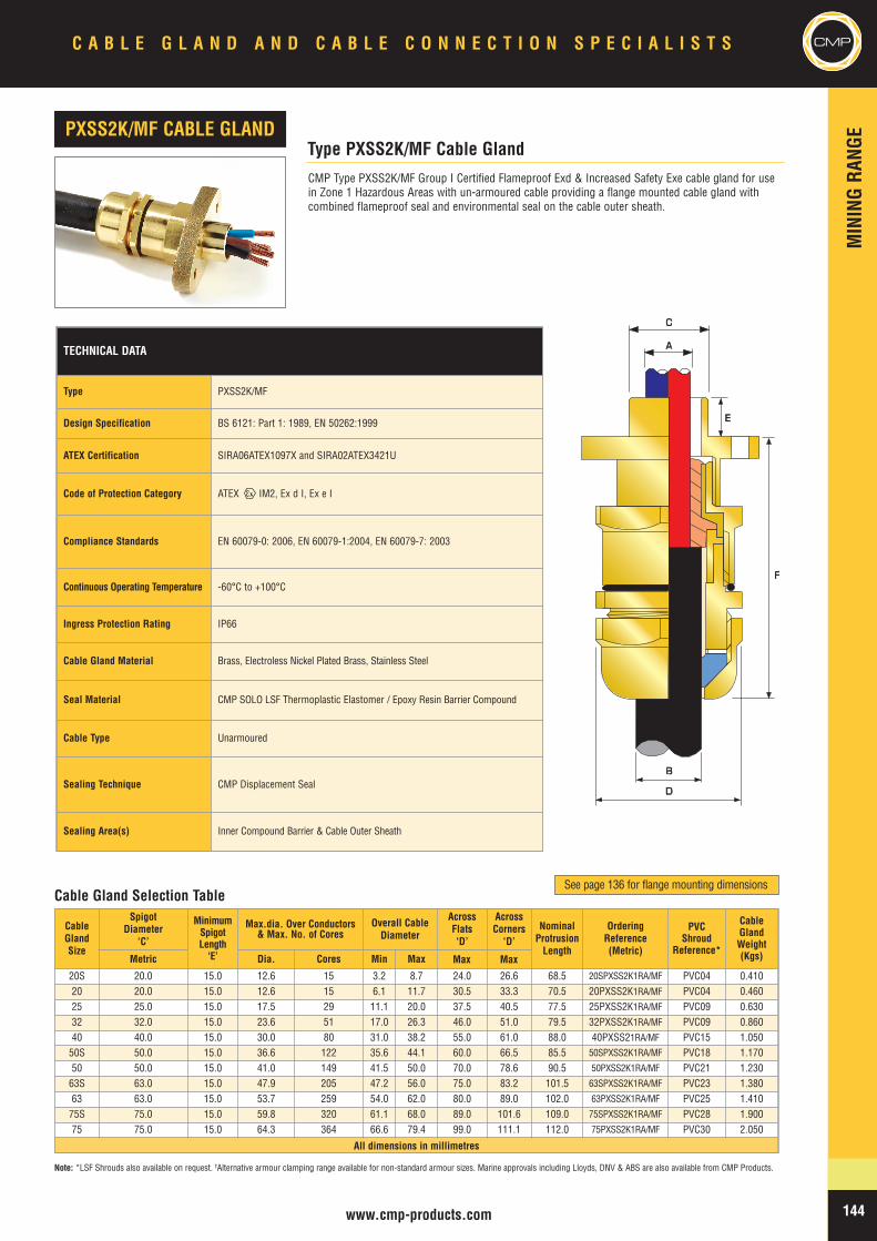
MIN
INGRA
NGE
CMPC A B L E G L A N D A N D C A B L E C O N N E C T I O N S P E C I A L I S T S
144www.cmp-products.com
TECHNICAL DATA
Type PXSS2K/MF
Design Specification BS 6121: Part 1: 1989, EN 50262:1999
ATEX Certification SIRA06ATEX1097X and SIRA02ATEX3421U
Code of Protection Category ATEX IM2, Ex d I, Ex e I
Compliance Standards EN 60079-0: 2006, EN 60079-1:2004, EN 60079-7: 2003
Continuous Operating Temperature -60°C to +100°C
Ingress Protection Rating IP66
Cable Gland Material Brass, Electroless Nickel Plated Brass, Stainless Steel
Seal Material CMP SOLO LSF Thermoplastic Elastomer / Epoxy Resin Barrier Compound
Cable Type Unarmoured
Sealing Technique CMP Displacement Seal
Sealing Area(s) Inner Compound Barrier & Cable Outer Sheath
CMP Type PXSS2K/MF Group I Certified Flameproof Exd & Increased Safety Exe cable gland for usein Zone 1 Hazardous Areas with un-armoured cable providing a flange mounted cable gland withcombined flameproof seal and environmental seal on the cable outer sheath.
Type PXSS2K/MF Cable GlandPXSS2K/MF CABLE GLAND
Note: *LSF Shrouds also available on request. †Alternative armour clamping range available for non-standard armour sizes. Marine approvals including Lloyds, DNV & ABS are also available from CMP Products.
CableGlandSize
SpigotDiameter
‘C’
MinimumSpigotLength‘E’
Max.dia. Over Conductors& Max. No. of Cores
Overall CableDiameter
AcrossFlats‘D’
AcrossCorners
‘D’NominalProtrusionLength
OrderingReference(Metric)
PVCShroud
Reference*
CableGlandWeight(Kgs)Metric Dia. Cores Min Max
20S 20.0 15.0 12.6 15 3.2 8.7 24.0 26.6 68.5 20SPXSS2K1RA/MF PVC04 0.41020 20.0 15.0 12.6 15 6.1 11.7 30.5 33.3 70.5 20PXSS2K1RA/MF PVC04 0.46025 25.0 15.0 17.5 29 11.1 20.0 37.5 40.5 77.5 25PXSS2K1RA/MF PVC09 0.63032 32.0 15.0 23.6 51 17.0 26.3 46.0 51.0 79.5 32PXSS2K1RA/MF PVC09 0.86040 40.0 15.0 30.0 80 31.0 38.2 55.0 61.0 88.0 40PXSS21RA/MF PVC15 1.05050S 50.0 15.0 36.6 122 35.6 44.1 60.0 66.5 85.5 50SPXSS2K1RA/MF PVC18 1.17050 50.0 15.0 41.0 149 41.5 50.0 70.0 78.6 90.5 50PXSS2K1RA/MF PVC21 1.23063S 63.0 15.0 47.9 205 47.2 56.0 75.0 83.2 101.5 63SPXSS2K1RA/MF PVC23 1.38063 63.0 15.0 53.7 259 54.0 62.0 80.0 89.0 102.0 63PXSS2K1RA/MF PVC25 1.41075S 75.0 15.0 59.8 320 61.1 68.0 89.0 101.6 109.0 75SPXSS2K1RA/MF PVC28 1.90075 75.0 15.0 64.3 364 66.6 79.4 99.0 111.1 112.0 75PXSS2K1RA/MF PVC30 2.050
All dimensions in millimetres
Cable Gland Selection Table
BB
DD
EE
FF
AA
CC
See page 136 for flange mounting dimensions
Max Max
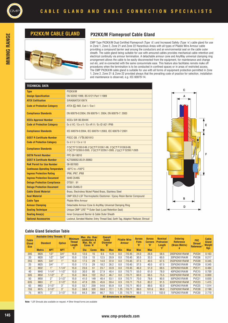
CMPMIN
INGRA
NGE
C A B L E G L A N D A N D C A B L E C O N N E C T I O N S P E C I A L I S T S
145 www.cmp-products.com
TECHNICAL DATA
Type PX2KX/M
Design Specification EN 50262:1999, BS 6121:Part 1:1989
ATEX Cetification SIRA06ATEX1097X
Code of Protection Category ATEX IM2, Exd I / Exe I
Compliance Standards EN 60079-0:2004, EN 60079-1: 2004, EN 60079-7: 2003
IECEx Approval Number IECEx SIR 06.0044X
Code of Protection Category Ex d IIC / Ex e II / Ex nR II / Ex tD A21 IP66
Compliance Standards IEC 60079-0:2004, IEC 60079-1:2003, IEC 60079-7:2001
GOST R Certificate Number POCC GB. 05.B01913
Code of Protection Category Ex d I U / Ex e I U
Compliance Standards P 51330.0-99, P 51330.1-99, P 51330.8-99,P 52350.0-2005, P 52350.1-2005, P 52350.7-2005
GGTN Permit Number PPC 00-18010
GOST K Certificate Number KZ7500052.05.01.00063
RoK Permit for Use Number 08-067693
Continuous Operating Temperature -60°C to +100°C
Ingress Protection Rating IP66, IP67, IP68
Ingress Protection Document 5046 C549G
Deluge Protection Compliance DTS01 : 91
Deluge Protection Document 5046 C549G-D
Cable Gland Material Brass, Electroless Nickel Plated Brass, Stainless Steel
Seal Material CMP SOLO LSF Thermoplastic Elastomer / Epoxy Resin Barrier Compound
Cable Type Pliable Wire Armour
Armour Clamping Detachable Armour Cone & AnyWay Universal Clamping Ring
Sealing Technique Unique CMP "LRS" ™ Outer Seal (Load Retention Seal)
Sealing Area(s) Inner Compound Barrier & Cable Outer Sheath
Optional Accessories Locknut, Serrated Washer, Entry Thread Seal, Earth Tag, Adaptor/ Reducer, Shroud
CMP Type PX2KX/M Dual Certified Flameproof (Type 'd') and Increased Safety (Type 'e') cable gland for usein Zone 1, Zone 2, Zone 21 and Zone 22 Hazardous Areas with all types of Pliable Wire Armour cableproviding a compound barrier seal aroung the conductors and an environmental seal on the cable outersheath. The cable gland being suitable for use with amoured cables provides mechanical cable retention andelectrical continuity via armour termination. A detachable armour cone and AnyWay universal clamping ringarrangement allows the cable to be easily disconnected from the equipment, for maintenance and changeout etc, and re-connected with the same consummate ease. This feature also facilitates remote make offprocedures when the termination is to be conducted in confined spaces or in areas of restricted access.The CMP PX2KX/M cable gland is suitable for use with all forms of equipment protection permitted in Zone1, Zone 2, Zone 21 & Zone 22 provided always that the prevailing code of practice for selection, installationand maintenance is observed, e.g. IEC 60079-14.
PX2KX/M Flameproof Cable GlandPX2KX/M CABLE GLAND
AA
BB
DD
CC
EE
FF
Cable Gland Selection Table
Note: *LSF Shrouds also available on request. # Other thread forms are available
LLU
CableGlandSize
Available Entry Threads ‘C’MinimumThreadLength‘E’
Max. dia. Overconductors &Max. No. ofCores ‘A’
OverallCable
Diameter‘B’
Pliable WireArmour
AcrossFlats‘D’
AcrossCorners
‘D’
NominalProtrusionLength‘F’
OrderingReference
(Brass Metric)#
PVCShroud
Reference*
CableGlandWeightKgs
Standard Option
Metric NPT NPT Dia Cores Min Max Min Max20S M20 1/2” 3/4” 15.0 12.6 15 9.5 15.9 0.0 7/0.45 24.0 26.6 58.5 20SPX2KX1RA/M PVC04 0.16320 M20 1/2” 3/4” 15.0 12.6 15 12.5 20.9 0.0 7/0.45 30.5 33.3 60.5 20PX2KX1RA/M PVC06 0.21725S M25 3/4” 1” 15.0 17.5 29 14.0 22.0 0.0 7/0.45 37.5 40.5 67.5 25SPX2KX1RA/M PVC09 0.34525 M25 3/4” 1” 15.0 17.5 29 18.2 26.2 0.0 7/0.45 37.5 40.5 67.5 25PX2KX1RA/M PVC09 0.34532 M32 1” 1-1/4” 15.0 23.6 51 23.7 33.9 0.0 7/0.45 46.0 51.0 69.5 32PX2KX1RA/M PVC11 0.48440 M40 1-1/4” 1-1/2” 15.0 30.0 80 27.9 40.4 0.0 7/0.71 55.0 61.0 78.0 40PX2KX1RA/M PVC15 0.70050S M50 1-1/2” 2” 15.0 36.6 122 35.2 46.7 0.0 7/0.71 60.0 66.5 75.5 50SPX2KX1RA/M PVC18 0.80050 M50 2” 2-1/2” 15.0 41.0 149 40.4 53.1 0.9 7/0.71 70.0 78.6 80.5 50PX2KX1RA/M PVC21 0.83063S M63 2” 2-1/2” 15.0 47.9 205 45.6 59.4 0.9 7/0.71 75.0 83.2 91.5 63SPX2KX1RA/M PVC23 1.41563 M63 2-1/2” 3” 15.0 53.7 259 54.6 65.9 0.9 7/0.71 80.0 89.0 92.0 63PX2KX1RA/M PVC25 1.51475S M75 2-1/2” 3” 15.0 59.8 320 59.0 72.1 1.25 7/0.71 89.0 101.6 99.0 75SPX2KX1RA/M PVC28 2.19975 M75 3” 3-1/2” 15.0 64.3 364 66.7 78.5 1.25 7/0.71 99.0 111.1 102.0 75PX2KX1RA/M PVC30 2.770
All dimensions in millimetres
OCTL
OCTL OCT
LOCT
L
OCTL
OCTL
Max Max
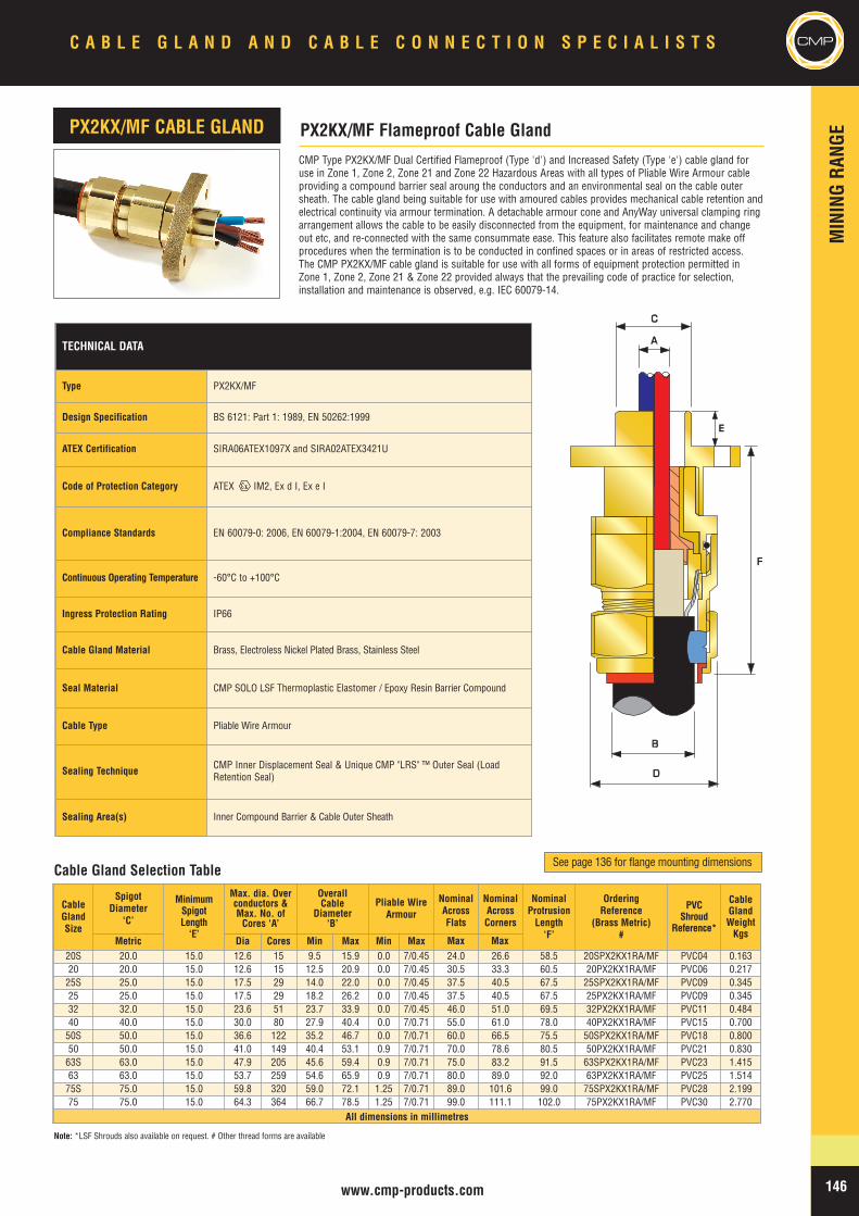
MIN
INGRA
NGE
146www.cmp-products.com
C A B L E G L A N D A N D C A B L E C O N N E C T I O N S P E C I A L I S T S CMP
CableGlandSize
SpigotDiameter
‘C’
MinimumSpigotLength‘E’
Max. dia. Overconductors &Max. No. ofCores ‘A’
OverallCable
Diameter‘B’
Pliable WireArmour
NominalAcrossFlats
NominalAcrossCorners
NominalProtrusionLength‘F’
OrderingReference
(Brass Metric)#
PVCShroud
Reference*
CableGlandWeightKgs
Metric Dia Cores Min Max Min Max20S 20.0 15.0 12.6 15 9.5 15.9 0.0 7/0.45 24.0 26.6 58.5 20SPX2KX1RA/MF PVC04 0.16320 20.0 15.0 12.6 15 12.5 20.9 0.0 7/0.45 30.5 33.3 60.5 20PX2KX1RA/MF PVC06 0.21725S 25.0 15.0 17.5 29 14.0 22.0 0.0 7/0.45 37.5 40.5 67.5 25SPX2KX1RA/MF PVC09 0.34525 25.0 15.0 17.5 29 18.2 26.2 0.0 7/0.45 37.5 40.5 67.5 25PX2KX1RA/MF PVC09 0.34532 32.0 15.0 23.6 51 23.7 33.9 0.0 7/0.45 46.0 51.0 69.5 32PX2KX1RA/MF PVC11 0.48440 40.0 15.0 30.0 80 27.9 40.4 0.0 7/0.71 55.0 61.0 78.0 40PX2KX1RA/MF PVC15 0.70050S 50.0 15.0 36.6 122 35.2 46.7 0.0 7/0.71 60.0 66.5 75.5 50SPX2KX1RA/MF PVC18 0.80050 50.0 15.0 41.0 149 40.4 53.1 0.9 7/0.71 70.0 78.6 80.5 50PX2KX1RA/MF PVC21 0.83063S 63.0 15.0 47.9 205 45.6 59.4 0.9 7/0.71 75.0 83.2 91.5 63SPX2KX1RA/MF PVC23 1.41563 63.0 15.0 53.7 259 54.6 65.9 0.9 7/0.71 80.0 89.0 92.0 63PX2KX1RA/MF PVC25 1.51475S 75.0 15.0 59.8 320 59.0 72.1 1.25 7/0.71 89.0 101.6 99.0 75SPX2KX1RA/MF PVC28 2.19975 75.0 15.0 64.3 364 66.7 78.5 1.25 7/0.71 99.0 111.1 102.0 75PX2KX1RA/MF PVC30 2.770
All dimensions in millimetres
CMP Type PX2KX/MF Dual Certified Flameproof (Type 'd') and Increased Safety (Type 'e') cable gland foruse in Zone 1, Zone 2, Zone 21 and Zone 22 Hazardous Areas with all types of Pliable Wire Armour cableproviding a compound barrier seal aroung the conductors and an environmental seal on the cable outersheath. The cable gland being suitable for use with amoured cables provides mechanical cable retention andelectrical continuity via armour termination. A detachable armour cone and AnyWay universal clamping ringarrangement allows the cable to be easily disconnected from the equipment, for maintenance and changeout etc, and re-connected with the same consummate ease. This feature also facilitates remote make offprocedures when the termination is to be conducted in confined spaces or in areas of restricted access.The CMP PX2KX/MF cable gland is suitable for use with all forms of equipment protection permitted inZone 1, Zone 2, Zone 21 & Zone 22 provided always that the prevailing code of practice for selection,installation and maintenance is observed, e.g. IEC 60079-14.
PX2KX/MF Flameproof Cable GlandPX2KX/MF CABLE GLAND
AA
BB
DD
CC
FF
EE
Cable Gland Selection Table
Note: *LSF Shrouds also available on request. # Other thread forms are available
See page 136 for flange mounting dimensions
Max Max
TECHNICAL DATA
Type PX2KX/MF
Design Specification BS 6121: Part 1: 1989, EN 50262:1999
ATEX Certification SIRA06ATEX1097X and SIRA02ATEX3421U
Code of Protection Category ATEX IM2, Ex d I, Ex e I
Compliance Standards EN 60079-0: 2006, EN 60079-1:2004, EN 60079-7: 2003
Continuous Operating Temperature -60°C to +100°C
Ingress Protection Rating IP66
Cable Gland Material Brass, Electroless Nickel Plated Brass, Stainless Steel
Seal Material CMP SOLO LSF Thermoplastic Elastomer / Epoxy Resin Barrier Compound
Cable Type Pliable Wire Armour
Sealing Technique CMP Inner Displacement Seal & Unique CMP "LRS" ™ Outer Seal (LoadRetention Seal)
Sealing Area(s) Inner Compound Barrier & Cable Outer Sheath
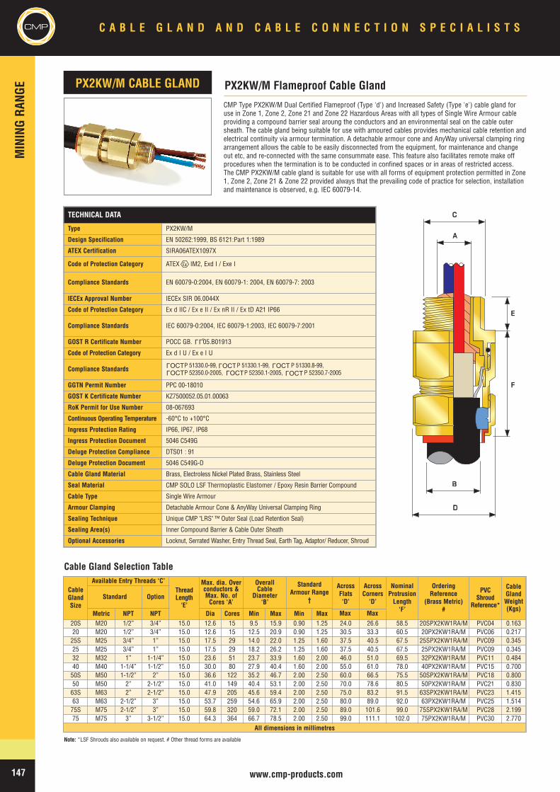
CMPMIN
INGRA
NGE
C A B L E G L A N D A N D C A B L E C O N N E C T I O N S P E C I A L I S T S
147 www.cmp-products.com
CMP Type PX2KW/M Dual Certified Flameproof (Type 'd') and Increased Safety (Type 'e') cable gland foruse in Zone 1, Zone 2, Zone 21 and Zone 22 Hazardous Areas with all types of Single Wire Armour cableproviding a compound barrier seal aroung the conductors and an environmental seal on the cable outersheath. The cable gland being suitable for use with amoured cables provides mechanical cable retention andelectrical continuity via armour termination. A detachable armour cone and AnyWay universal clamping ringarrangement allows the cable to be easily disconnected from the equipment, for maintenance and changeout etc, and re-connected with the same consummate ease. This feature also facilitates remote make offprocedures when the termination is to be conducted in confined spaces or in areas of restricted access.The CMP PX2KW/M cable gland is suitable for use with all forms of equipment protection permitted in Zone1, Zone 2, Zone 21 & Zone 22 provided always that the prevailing code of practice for selection, installationand maintenance is observed, e.g. IEC 60079-14.
PX2KW/M Flameproof Cable GlandPX2KW/M CABLE GLAND
AA
BB
DD
CC
EE
FF
Cable Gland Selection Table
Note: *LSF Shrouds also available on request. # Other thread forms are available
CableGlandSize
Available Entry Threads ‘C’ThreadLength‘E’
Max. dia. Overconductors &Max. No. ofCores ‘A’
OverallCable
Diameter‘B’
StandardArmour Range
†
AcrossFlats‘D’
AcrossCorners
‘D’
NominalProtrusionLength‘F’
OrderingReference
(Brass Metric)#
PVCShroud
Reference*
CableGlandWeight(Kgs)
Standard Option
Metric NPT NPT Dia Cores Min Max Min Max20S M20 1/2” 3/4” 15.0 12.6 15 9.5 15.9 0.90 1.25 24.0 26.6 58.5 20SPX2KW1RA/M PVC04 0.16320 M20 1/2” 3/4” 15.0 12.6 15 12.5 20.9 0.90 1.25 30.5 33.3 60.5 20PX2KW1RA/M PVC06 0.21725S M25 3/4” 1” 15.0 17.5 29 14.0 22.0 1.25 1.60 37.5 40.5 67.5 25SPX2KW1RA/M PVC09 0.34525 M25 3/4” 1” 15.0 17.5 29 18.2 26.2 1.25 1.60 37.5 40.5 67.5 25PX2KW1RA/M PVC09 0.34532 M32 1” 1-1/4” 15.0 23.6 51 23.7 33.9 1.60 2.00 46.0 51.0 69.5 32PX2KW1RA/M PVC11 0.48440 M40 1-1/4” 1-1/2” 15.0 30.0 80 27.9 40.4 1.60 2.00 55.0 61.0 78.0 40PX2KW1RA/M PVC15 0.70050S M50 1-1/2” 2” 15.0 36.6 122 35.2 46.7 2.00 2.50 60.0 66.5 75.5 50SPX2KW1RA/M PVC18 0.80050 M50 2” 2-1/2” 15.0 41.0 149 40.4 53.1 2.00 2.50 70.0 78.6 80.5 50PX2KW1RA/M PVC21 0.83063S M63 2” 2-1/2” 15.0 47.9 205 45.6 59.4 2.00 2.50 75.0 83.2 91.5 63SPX2KW1RA/M PVC23 1.41563 M63 2-1/2” 3” 15.0 53.7 259 54.6 65.9 2.00 2.50 80.0 89.0 92.0 63PX2KW1RA/M PVC25 1.51475S M75 2-1/2” 3” 15.0 59.8 320 59.0 72.1 2.00 2.50 89.0 101.6 99.0 75SPX2KW1RA/M PVC28 2.19975 M75 3” 3-1/2” 15.0 64.3 364 66.7 78.5 2.00 2.50 99.0 111.1 102.0 75PX2KW1RA/M PVC30 2.770
All dimensions in millimetres
TECHNICAL DATA
Type PX2KW/M
Design Specification EN 50262:1999, BS 6121:Part 1:1989
ATEX Certification SIRA06ATEX1097X
Code of Protection Category ATEX IM2, Exd I / Exe I
Compliance Standards EN 60079-0:2004, EN 60079-1: 2004, EN 60079-7: 2003
IECEx Approval Number IECEx SIR 06.0044X
Code of Protection Category Ex d IIC / Ex e II / Ex nR II / Ex tD A21 IP66
Compliance Standards IEC 60079-0:2004, IEC 60079-1:2003, IEC 60079-7:2001
GOST R Certificate Number POCC GB. 05.B01913
Code of Protection Category Ex d I U / Ex e I U
Compliance Standards P 51330.0-99, P 51330.1-99, P 51330.8-99,P 52350.0-2005, P 52350.1-2005, P 52350.7-2005
GGTN Permit Number PPC 00-18010
GOST K Certificate Number KZ7500052.05.01.00063
RoK Permit for Use Number 08-067693
Continuous Operating Temperature -60°C to +100°C
Ingress Protection Rating IP66, IP67, IP68
Ingress Protection Document 5046 C549G
Deluge Protection Compliance DTS01 : 91
Deluge Protection Document 5046 C549G-D
Cable Gland Material Brass, Electroless Nickel Plated Brass, Stainless Steel
Seal Material CMP SOLO LSF Thermoplastic Elastomer / Epoxy Resin Barrier Compound
Cable Type Single Wire Armour
Armour Clamping Detachable Armour Cone & AnyWay Universal Clamping Ring
Sealing Technique Unique CMP "LRS" ™ Outer Seal (Load Retention Seal)
Sealing Area(s) Inner Compound Barrier & Cable Outer Sheath
Optional Accessories Locknut, Serrated Washer, Entry Thread Seal, Earth Tag, Adaptor/ Reducer, Shroud
LLU
OCTL
OCTL OCT
LOCT
L
OCTL
OCTL
Max Max
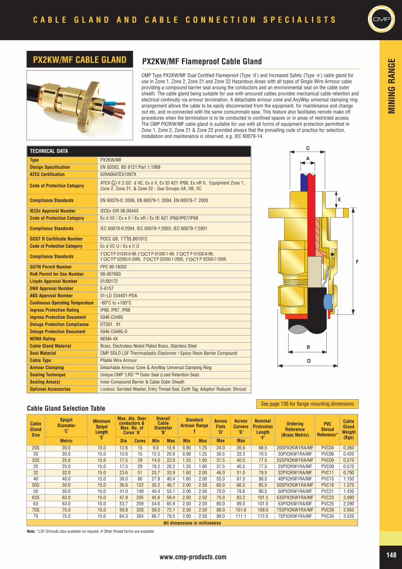
MIN
INGRA
NGE
148www.cmp-products.com
CMPC A B L E G L A N D A N D C A B L E C O N N E C T I O N S P E C I A L I S T S
TECHNICAL DATA
Type PX2KW/MFDesign Specification EN 50262, BS 6121:Part 1:1989ATEX Certification SIRA06ATEX1097X
Code of Protection Category ATEX II 2 GD d IIC, Ex e II, Ex tD A21 IP66, Ex nR II, Equipment Zone 1,Zone 2, Zone 21, & Zone 22 - Gas Groups IIA, IIB, IIC
Compliance Standards EN 60079-0: 2006, EN 60079-1: 2004, EN 60079-7: 2003
IECEx Approval Number IECEx SIR 06.0044XCode of Protection Category Ex d IIC / Ex e II / Ex nR / Ex tD A21 IP66/IP67/IP68
Compliance Standards IEC 60079-0:2004, IEC 60079-1:2003, IEC 60079-7:2001
GOST R Certificate Number POCC GB. 05.B01912Code of Protection Category Ex d IIC U / Ex e II U
Compliance Standards P 51330.0-99, P 51330.1-99, P 51330.8-99,P 52350.0-2005, P 52350.1-2005, P 52350.7-2005
GGTN Permit Number PPC 00-18262RoK Permit for Use Number 08-067693Lloyds Approval Number 01/00172DNV Approval Number E-6157ABS Approval Number 01-LD 234401-PDAContinuous Operating Temperature -60°C to +100°CIngress Protection Rating IP66, IP67, IP68Ingress Protection Document 5046 C549GDeluge Protection Compliance DTS01 : 91Deluge Protection Document 5046 C549G-DNEMA Rating NEMA 4XCable Gland Material Brass, Electroless Nickel Plated Brass, Stainless SteelSeal Material CMP SOLO LSF Thermoplastic Elastomer / Epoxy Resin Barrier CompoundCable Type Pliable Wire ArmourArmour Clamping Detachable Armour Cone & AnyWay Universal Clamping RingSealing Technique Unique CMP "LRS" ™ Outer Seal (Load Retention Seal)Sealing Area(s) Inner Compound Barrier & Cable Outer SheathOptional Accessories Locknut, Serrated Washer, Entry Thread Seal, Earth Tag, Adaptor/ Reducer, Shroud
LLU
OCTL
OCTL OCT
LOCT
L
OCTL
OCTL
CMP Type PX2KW/MF Dual Certified Flameproof (Type 'd') and Increased Safety (Type 'e') cable gland foruse in Zone 1, Zone 2, Zone 21 and Zone 22 Hazardous Areas with all types of Single Wire Armour cableproviding a compound barrier seal aroung the conductors and an environmental seal on the cable outersheath. The cable gland being suitable for use with amoured cables provides mechanical cable retention andelectrical continuity via armour termination. A detachable armour cone and AnyWay universal clamping ringarrangement allows the cable to be easily disconnected from the equipment, for maintenance and changeout etc, and re-connected with the same consummate ease. This feature also facilitates remote make offprocedures when the termination is to be conducted in confined spaces or in areas of restricted access.The CMP PX2KW/MF cable gland is suitable for use with all forms of equipment protection permitted inZone 1, Zone 2, Zone 21 & Zone 22 provided always that the prevailing code of practice for selection,installation and maintenance is observed, e.g. IEC 60079-14.
PX2KW/MF Flameproof Cable GlandPX2KW/MF CABLE GLAND
AA
BB
DD
CC
FF
EE
Cable Gland Selection Table
Note: *LSF Shrouds also available on request. # Other thread forms are available
See page 136 for flange mounting dimensions
CableGlandSize
SpigotDiameter
‘C’
MinimumSpigotLength‘E’
Max. dia. Overconductors &Max. No. ofCores ‘A’
OverallCable
Diameter‘B’
StandardArmour Range
†
AcrossFlats‘D’
AcrossCorners
‘D’
NominalProtrusionLength‘F’
OrderingReference
(Brass Metric)
PVCShroud
Reference*
CableGlandWeight(Kgs)
Metric Dia Cores Min Max Min Max20S 20.0 15.0 12.6 15 9.5 15.9 0.90 1.25 24.0 26.6 68.5 20SPX2KW1RA/MF PVC04 0.36020 20.0 15.0 12.6 15 12.5 20.9 0.90 1.25 30.5 33.3 70.5 20PX2KW1RA/MF PVC06 0.42025S 25.0 15.0 17.5 29 14.0 22.0 1.25 1.60 37.5 40.5 77.5 25SPX2KW1RA/MF PVC09 0.57025 25.0 15.0 17.5 29 18.2 26.2 1.25 1.60 37.5 40.5 77.5 25PX2KW1RA/MF PVC09 0.57032 32.0 15.0 23.6 51 23.7 33.9 1.60 2.00 46.0 51.0 79.5 32PX2KW1RA/MF PVC11 0.79040 40.0 15.0 30.0 80 27.9 40.4 1.60 2.00 55.0 61.0 88.0 40PX2KW1RA/MF PVC15 1.15050S 50.0 15.0 36.6 122 35.2 46.7 2.00 2.50 60.0 66.5 85.5 50SPX2KW1RA/MF PVC18 1.37050 50.0 15.0 41.0 149 40.4 53.1 2.00 2.50 70.0 78.6 90.5 50PX2KW1RA/MF PVC21 1.43063S 63.0 15.0 47.9 205 45.6 59.4 2.00 2.50 75.0 83.2 101.5 63SPX2KW1RA/MF PVC23 2.09063 63.0 15.0 53.7 259 54.6 65.9 2.00 2.50 80.0 89.0 101.5 63PX2KW1RA/MF PVC25 2.29075S 75.0 15.0 59.8 320 59.0 72.1 2.00 2.50 89.0 101.6 109.0 75SPX2KW1RA/MF PVC28 2.95075 75.0 15.0 64.3 364 66.7 78.5 2.00 2.50 99.0 111.1 112.0 75PX2KW1RA/MF PVC30 3.520
All dimensions in millimetres
Max Max
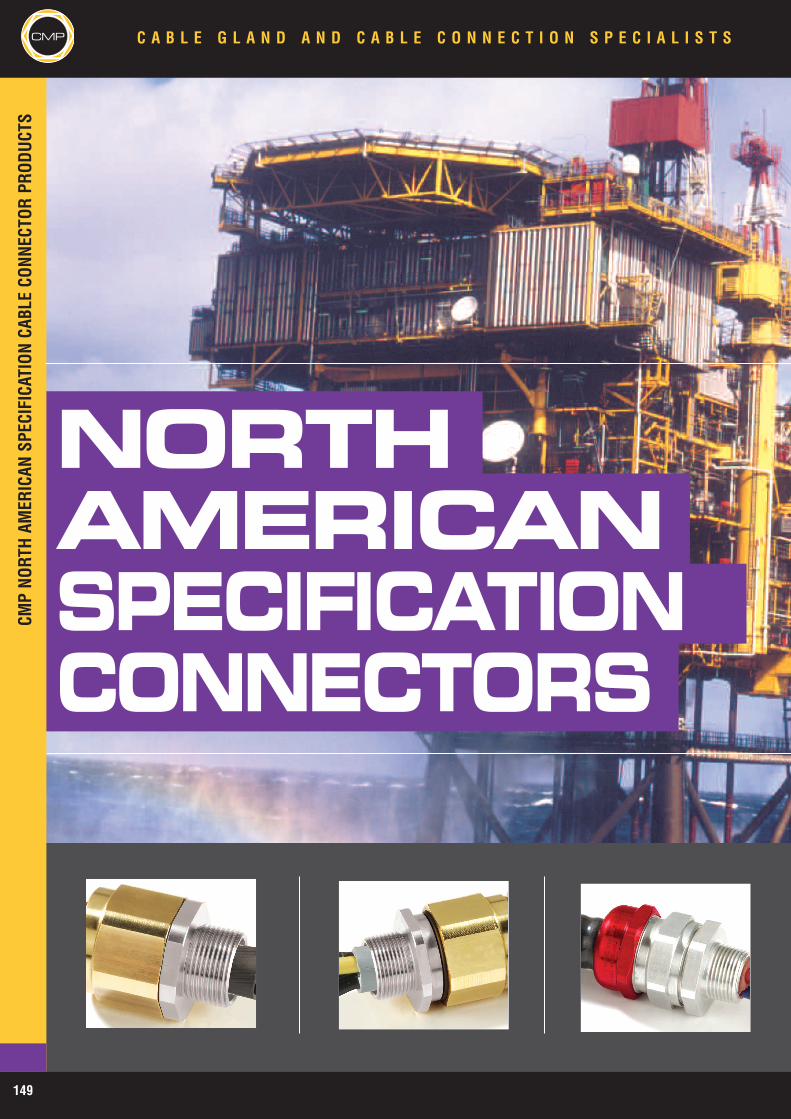
NORTHAMERICANSPECIFICATIONCONNECTORS
CMPNO
RTHAM
ERICAN
SPEC
IFICAT
IONCA
BLECO
NNEC
TORPR
ODUC
TSCMP C A B L E G L A N D A N D C A B L E C O N N E C T I O N S P E C I A L I S T S
149

CMPNO
RTHAM
ERICAN
SPEC
IFICAT
IONCA
BLECO
NNEC
TORPR
ODUC
TS
C A B L E G L A N D A N D C A B L E C O N N E C T I O N S P E C I A L I S T S CMP
APPLICATION
The CMP range of Cable Connectors & CableGlands for Hazardous and Wet Locations areversatile enough to meet virtually all situationswhere flexible and non flexible cables are usedinstead of pipe conduit systems. Designed forboth offshore and onshore requirements theoptions available cover Armoured, Armored &Jacketed and Non-Armored (e.g. IEEE45) Typesand also Interlocked or Corrugated ContinuouslyWelded MC (or MC-HL), and Teck cables.
150
PRODUCTS
Solutions for virtually all-conceivable cablespermitted for use in hazardous locations wheninstalled in both Class / Divisions and Class /Zones classification concepts.
SPECIFICATIONS & APPROVALS
CMP Hazardous Location Cable Connectorscomply with prevailing UL, ISA & ANSIStandards and meet the requirements of NECand CEC installation code requirements. Inaddition product compliance with ABS and USCoast Guards USCG14CFR requirements is alsooffered.
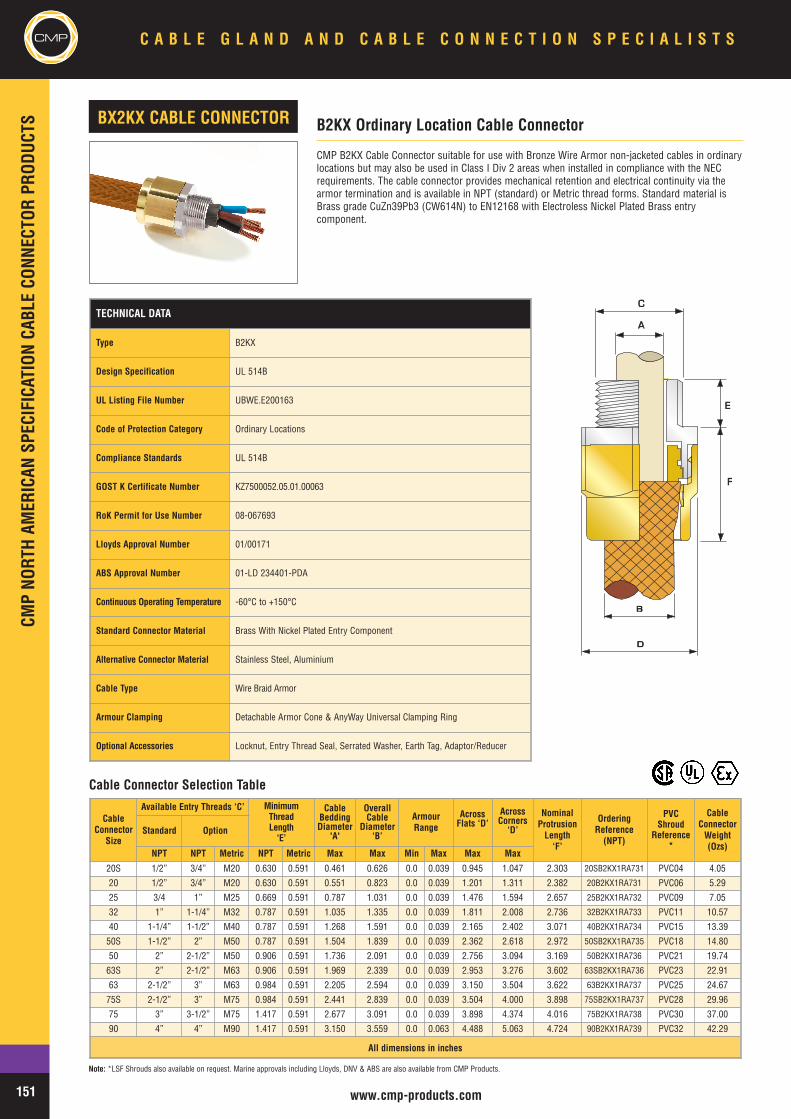
CMPCM
PNO
RTHAM
ERICAN
SPEC
IFICAT
IONCA
BLECO
NNEC
TORPR
ODUC
TSC A B L E G L A N D A N D C A B L E C O N N E C T I O N S P E C I A L I S T S
151 www.cmp-products.com
TECHNICAL DATA
Type B2KX
Design Specification UL 514B
UL Listing File Number UBWE.E200163
Code of Protection Category Ordinary Locations
Compliance Standards UL 514B
GOST K Certificate Number KZ7500052.05.01.00063
RoK Permit for Use Number 08-067693
Lloyds Approval Number 01/00171
ABS Approval Number 01-LD 234401-PDA
Continuous Operating Temperature -60°C to +150°C
Standard Connector Material Brass With Nickel Plated Entry Component
Alternative Connector Material Stainless Steel, Aluminium
Cable Type Wire Braid Armor
Armour Clamping Detachable Armor Cone & AnyWay Universal Clamping Ring
Optional Accessories Locknut, Entry Thread Seal, Serrated Washer, Earth Tag, Adaptor/Reducer
CMP B2KX Cable Connector suitable for use with Bronze Wire Armor non-jacketed cables in ordinarylocations but may also be used in Class I Div 2 areas when installed in compliance with the NECrequirements. The cable connector provides mechanical retention and electrical continuity via thearmor termination and is available in NPT (standard) or Metric thread forms. Standard material isBrass grade CuZn39Pb3 (CW614N) to EN12168 with Electroless Nickel Plated Brass entrycomponent.
CableConnector
Size
Available Entry Threads ‘C’ MinimumThreadLength‘E’
CableBeddingDiameter
'A'
OverallCable
Diameter‘B’
ArmourRange
AcrossFlats ‘D’
AcrossCorners
‘D’
NominalProtrusionLength‘F’
OrderingReference
(NPT)
PVCShroud
Reference*
CableConnectorWeight(Ozs)
Standard Option
NPT NPT Metric NPT Metric Max Max Min Max Max Max
20S 1/2” 3/4” M20 0.630 0.591 0.461 0.626 0.0 0.039 0.945 1.047 2.303 20SB2KX1RA731 PVC04 4.05
20 1/2” 3/4” M20 0.630 0.591 0.551 0.823 0.0 0.039 1.201 1.311 2.382 20B2KX1RA731 PVC06 5.29
25 3/4 1” M25 0.669 0.591 0.787 1.031 0.0 0.039 1.476 1.594 2.657 25B2KX1RA732 PVC09 7.05
32 1” 1-1/4” M32 0.787 0.591 1.035 1.335 0.0 0.039 1.811 2.008 2.736 32B2KX1RA733 PVC11 10.57
40 1-1/4” 1-1/2” M40 0.787 0.591 1.268 1.591 0.0 0.039 2.165 2.402 3.071 40B2KX1RA734 PVC15 13.39
50S 1-1/2” 2” M50 0.787 0.591 1.504 1.839 0.0 0.039 2.362 2.618 2.972 50SB2KX1RA735 PVC18 14.80
50 2” 2-1/2” M50 0.906 0.591 1.736 2.091 0.0 0.039 2.756 3.094 3.169 50B2KX1RA736 PVC21 19.74
63S 2” 2-1/2” M63 0.906 0.591 1.969 2.339 0.0 0.039 2.953 3.276 3.602 63SB2KX1RA736 PVC23 22.91
63 2-1/2” 3” M63 0.984 0.591 2.205 2.594 0.0 0.039 3.150 3.504 3.622 63B2KX1RA737 PVC25 24.67
75S 2-1/2” 3” M75 0.984 0.591 2.441 2.839 0.0 0.039 3.504 4.000 3.898 75SB2KX1RA737 PVC28 29.96
75 3” 3-1/2” M75 1.417 0.591 2.677 3.091 0.0 0.039 3.898 4.374 4.016 75B2KX1RA738 PVC30 37.00
90 4” 4” M90 1.417 0.591 3.150 3.559 0.0 0.063 4.488 5.063 4.724 90B2KX1RA739 PVC32 42.29
All dimensions in inches
B2KX Ordinary Location Cable ConnectorBX2KX CABLE CONNECTOR
AA
CC
EE
BB
DD
FF
Note: *LSF Shrouds also available on request. Marine approvals including Lloyds, DNV & ABS are also available from CMP Products.
Cable Connector Selection Table

CMP
NORT
H AM
ERIC
AN S
PECI
FICA
TION
CAB
LE C
ONNE
CTOR
PRO
DUCT
S
CMPC A B L E G L A N D A N D C A B L E C O N N E C T I O N S P E C I A L I S T S
152www.cmp-products.com
TECHNICAL DATA
Type C2KX
Design Specification UL 514B, EN 50262:1999
UL Listing File Number UBWE.E200163, FDJR.E256367
Code of Protection Category Ordinary & Wet Locations, Class I, Div 2, *ABCD, Class I, Zone 1, AEx e II,Class I, Zone 2, AEx e II (*When installed in compliance with the NEC)
Compliance Standards UL 514B, ANSI / UL 60079-0, ANSI / UL 60079-7
Lloyds Approval Number 01/00171
GOST K Certificate Number KZ7500052.05.01.00063
RoK Permit for Use Number 08-067693
DNV Approval Number E-6157
ABS Approval Number 01-LD 234401-PDA
Continuous Operating Temperature -60°C to +130°C
Ingress Protection Rating IP66, IP67, IP68
Ingress Protection Document 5046 C549G
Deluge Protection Compliance DTS01 : 91
Code of Protection Category 5046 C549G-D
NEMA Rating NEMA 4X
Standard Connector Material Brass With Nickel Plated Entry Component
Alternative Connector Material Brass, Nickel Plated Brass, Stainless Steel
Seal Material CMP SOLO LSF Thermoplastic Elastomer
Cable Type Armored & Jacketed
Armour Clamping Detachable Armour Cone & AnyWay Universal Clamping Ring
Sealing Technique Unique CMP "LRS" ™ Outer Seal (Load Retention Seal)
Sealing Area(s) Cable Outer Jacket
Optional Accessories Locknut, Shroud, Entry Thread Seal, Serrated Washer, Earth Tag,Adaptor/Reducer
CableConnector
Size
Available Entry Threads‘C’
MinimumThreadLength
‘E’
CableBeddingDiameter
‘A’
Overall Cable
Diameter‘B’
ArmourRange
AcrossFlats ‘D’
AcrossCorners
‘D’
NominalProtrusion
Length‘F’
OrderingReference
(NPT)
PVCShroud
Reference*
CableConnector
Weight(Ozs)
Standard Option
NPT NPT Metric NPT Metric Max Min Max Min Max Max Max20S/16 1/2” 3/4” M20 0.630 0.591 0.461 0.240 0.453 0.0 0.039 0.945 1.047 2.303 20S16C2KX1RA731 PVC04 4.65
20S 1/2” 3/4” M20 0.630 0.591 0.461 0.374 0.626 0.0 0.039 0.945 1.047 2.303 20SC2KX1RA731 PVC04 4.6520 1/2” 3/4” M20 0.630 0.591 0.551 0.492 0.823 0.0 0.039 1.201 1.311 2.382 20C2KX1RA731 PVC06 6.84
25S 3/4” 1” M25 0.669 0.591 0.787 0.551 0.866 0.0 0.039 1.476 1.594 2.657 25C2KX1RA732 PVC09 10.7825 3/4” 1” M25 0.669 0.591 0.787 0.717 1.031 0.0 0.039 1.476 1.594 2.657 25C2KX1RA732 PVC09 10.7832 1” 1-1/4” M32 0.787 0.591 1.035 0.933 1.335 0.0 0.039 1.811 2.008 2.736 32C2KX1RA733 PVC11 16.4940 1-1/4” 1-1/2” M40 0.787 0.591 1.268 1.098 1.591 0.0 0.039 2.165 2.402 3.071 40C2KX1RA734 PVC15 23.89
50S 1-1/2” 2” M50 0.787 0.591 1.504 1.386 1.839 0.0 0.039 2.362 2.618 2.972 50SC2KX1RA735 PVC18 26.4350 2” 2-1/2” M50 0.906 0.591 1.736 1.591 2.091 0.0 0.039 2.756 3.094 3.169 50SC2KX1RA736 PVC21 36.79
63S 2” 2-1/2” M63 0.906 0.591 1.969 1.795 2.339 0.0 0.039 2.953 3.276 3.602 63SC2KX1RA736 PVC23 37.8563 2-1/2” 3” M63 0.984 0.591 2.205 2.150 2.594 0.0 0.039 3.150 3.504 3.622 63C2KX1RA737 PVC25 45.11
75S 2-1/2” 3” M75 0.984 0.591 2.441 2.323 2.839 0.0 0.039 3.504 4.000 3.898 75SC2KX1RA737 PVC28 65.5575 3” 3-1/2” M75 1.417 0.591 2.677 2.626 3.091 0.0 0.039 3.898 4.374 4.016 75C2KX1RA738 PVC30 89.8790 3-1/2” 4” M90 1.417 0.591 3.150 3.000 3.559 0.0 0.063 4.488 5.063 4.724 90C2KX1RA739 PVC32 128.63
All dimensions in inches
CMP C2KX Cable Connector suitable for use with Armored & Jacketed cables incorporating WireBraid Armor in Ordinary, Wet & Hazardous Locations. The cable connector provides mechanicalretention and electrical continuity via the armor termination and is available in NPT (standard) orMetric thread forms. Standard material is Brass grade CuZn39Pb3 (CW614N) to EN12168 withElectroless Nickel Plated Brass entry component. This product provides Nema 4X and IP68 ingressprotection and is UL listed for use in Class I Zone I AEx e II applications and can be used in Class IDivision 2 areas when installed in compliance with the NEC requirements.
C2KX Ordinary, Wet & Hazardous Location Cable ConnectorC2KX CABLE CONNECTOR
A
B
D
C
E
F
Note: *LSF Shrouds also available on request. Marine approvals including Lloyds, DNV & ABS are also available from CMP Products.
Cable Connector Selection Table
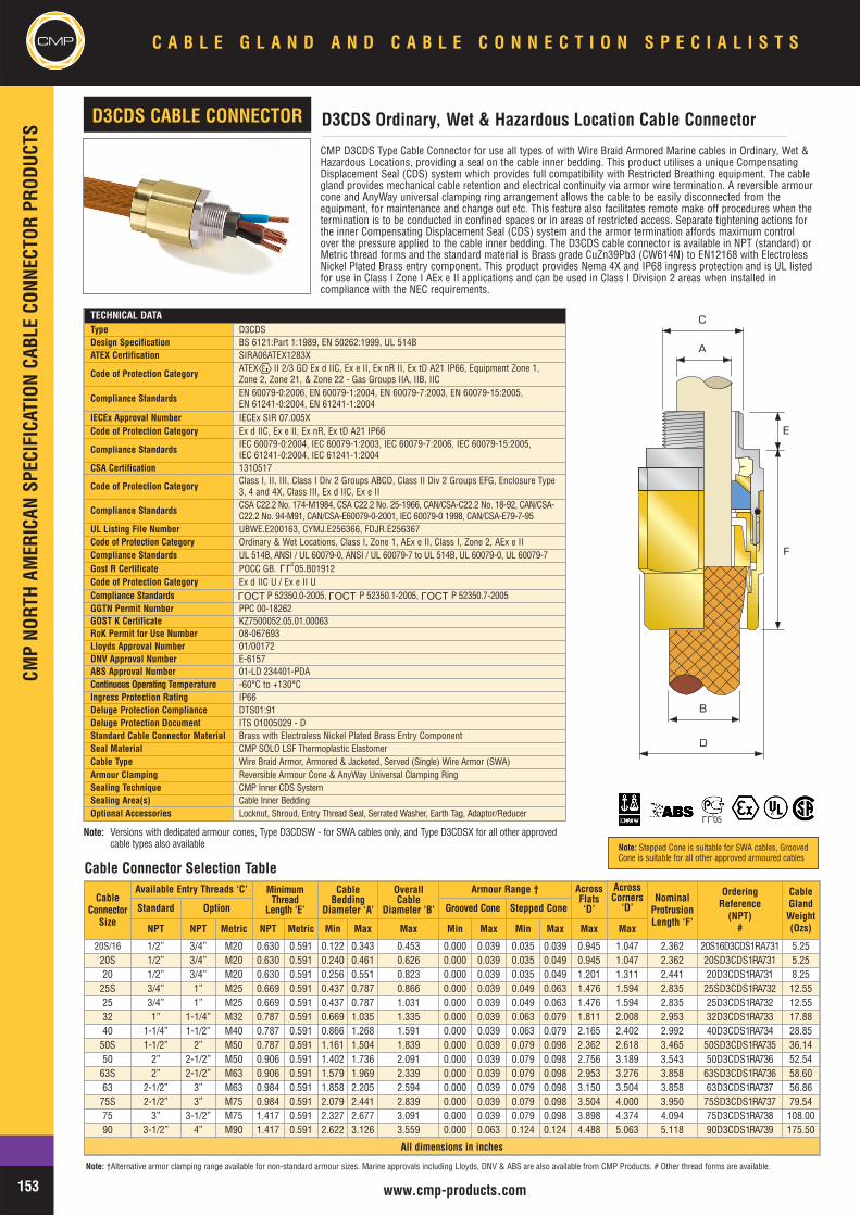
CMPCM
P NO
RTH
AMER
ICAN
SPE
CIFI
CATI
ON C
ABLE
CON
NECT
OR P
RODU
CTS
C A B L E G L A N D A N D C A B L E C O N N E C T I O N S P E C I A L I S T S
153 www.cmp-products.com
Note: Stepped Cone is suitable for SWA cables, GroovedCone is suitable for all other approved armoured cables
CMP D3CDS Type Cable Connector for use all types of with Wire Braid Armored Marine cables in Ordinary, Wet &Hazardous Locations, providing a seal on the cable inner bedding. This product utilises a unique CompensatingDisplacement Seal (CDS) system which provides full compatibility with Restricted Breathing equipment. The cablegland provides mechanical cable retention and electrical continuity via armor wire termination. A reversible armourcone and AnyWay universal clamping ring arrangement allows the cable to be easily disconnected from theequipment, for maintenance and change out etc. This feature also facilitates remote make off procedures when thetermination is to be conducted in confined spaces or in areas of restricted access. Separate tightening actions forthe inner Compensating Displacement Seal (CDS) system and the armor termination affords maximum controlover the pressure applied to the cable inner bedding. The D3CDS cable connector is available in NPT (standard) orMetric thread forms and the standard material is Brass grade CuZn39Pb3 (CW614N) to EN12168 with ElectrolessNickel Plated Brass entry component. This product provides Nema 4X and IP68 ingress protection and is UL listedfor use in Class I Zone I AEx e II applications and can be used in Class I Division 2 areas when installed incompliance with the NEC requirements.
Note: Versions with dedicated armour cones, Type D3CDSW - for SWA cables only, and Type D3CDSX for all other approved cable types also available
TECHNICAL DATAType D3CDSDesign Specification BS 6121:Part 1:1989, EN 50262:1999, UL 514BATEX Certification SIRA06ATEX1283X
Code of Protection Category ATEX II 2/3 GD Ex d IIC, Ex e II, Ex nR II, Ex tD A21 IP66, Equipment Zone 1,Zone 2, Zone 21, & Zone 22 - Gas Groups IIA, IIB, IIC
Compliance Standards EN 60079-0:2006, EN 60079-1:2004, EN 60079-7:2003, EN 60079-15:2005, EN 61241-0:2004, EN 61241-1:2004
IECEx Approval Number IECEx SIR 07.005XCode of Protection Category Ex d IIC, Ex e II, Ex nR, Ex tD A21 IP66
Compliance Standards IEC 60079-0:2004, IEC 60079-1:2003, IEC 60079-7:2006, IEC 60079-15:2005, IEC 61241-0:2004, IEC 61241-1:2004
CSA Certification 1310517
Code of Protection Category Class I, II, III, Class I Div 2 Groups ABCD, Class II Div 2 Groups EFG, Enclosure Type3, 4 and 4X, Class III, Ex d IIC, Ex e II
Compliance Standards CSA C22.2 No. 174-M1984, CSA C22.2 No. 25-1966, CAN/CSA-C22.2 No. 18-92, CAN/CSA-C22.2 No. 94-M91, CAN/CSA-E60079-0-2001, IEC 60079-0 1998, CAN/CSA-E79-7-95
UL Listing File Number UBWE.E200163, CYMJ.E256366, FDJR.E256367Code of Protection Category Ordinary & Wet Locations, Class I, Zone 1, AEx e II, Class I, Zone 2, AEx e IICompliance Standards UL 514B, ANSI / UL 60079-0, ANSI / UL 60079-7 to UL 514B, UL 60079-0, UL 60079-7Gost R Certificate POCC GB. 05.B01912Code of Protection Category Ex d IIC U / Ex e II UCompliance Standards P 52350.0-2005, P 52350.1-2005, P 52350.7-2005GGTN Permit Number PPC 00-18262GOST K Certificate KZ7500052.05.01.00063RoK Permit for Use Number 08-067693Lloyds Approval Number 01/00172DNV Approval Number E-6157ABS Approval Number 01-LD 234401-PDAContinuous Operating Temperature -60°C to +130°CIngress Protection Rating IP66Deluge Protection Compliance DTS01:91Deluge Protection Document ITS 01005029 - DStandard Cable Connector Material Brass with Electroless Nickel Plated Brass Entry ComponentSeal Material CMP SOLO LSF Thermoplastic ElastomerCable Type Wire Braid Armor, Armored & Jacketed, Served (Single) Wire Armor (SWA)Armour Clamping Reversible Armour Cone & AnyWay Universal Clamping RingSealing Technique CMP Inner CDS SystemSealing Area(s) Cable Inner BeddingOptional Accessories Locknut, Shroud, Entry Thread Seal, Serrated Washer, Earth Tag, Adaptor/Reducer
D3CDS Ordinary, Wet & Hazardous Location Cable Connector D3CDS CABLE CONNECTOR
CableConnector
Size
Available Entry Threads ‘C’ Minimum Thread
Length ‘E’
CableBedding
Diameter ‘A’
Overall Cable
Diameter ‘B’
Armour Range † AcrossFlats‘D’
AcrossCorners
‘D’Nominal
ProtrusionLength ‘F’
OrderingReference
(NPT)#
CableGlandWeight(Ozs)
Standard Option Grooved Cone Stepped Cone
NPT NPT Metric NPT Metric Min Max Max Min Max Min Max Max Max
20S/16 1/2” 3/4” M20 0.630 0.591 0.122 0.343 0.453 0.000 0.039 0.035 0.039 0.945 1.047 2.362 20S16D3CDS1RA731 5.2520S 1/2” 3/4” M20 0.630 0.591 0.240 0.461 0.626 0.000 0.039 0.035 0.049 0.945 1.047 2.362 20SD3CDS1RA731 5.2520 1/2” 3/4” M20 0.630 0.591 0.256 0.551 0.823 0.000 0.039 0.035 0.049 1.201 1.311 2.441 20D3CDS1RA731 8.25
25S 3/4” 1” M25 0.669 0.591 0.437 0.787 0.866 0.000 0.039 0.049 0.063 1.476 1.594 2.835 25SD3CDS1RA732 12.5525 3/4” 1” M25 0.669 0.591 0.437 0.787 1.031 0.000 0.039 0.049 0.063 1.476 1.594 2.835 25D3CDS1RA732 12.5532 1” 1-1/4” M32 0.787 0.591 0.669 1.035 1.335 0.000 0.039 0.063 0.079 1.811 2.008 2.953 32D3CDS1RA733 17.8840 1-1/4” 1-1/2” M40 0.787 0.591 0.866 1.268 1.591 0.000 0.039 0.063 0.079 2.165 2.402 2.992 40D3CDS1RA734 28.85
50S 1-1/2” 2” M50 0.787 0.591 1.161 1.504 1.839 0.000 0.039 0.079 0.098 2.362 2.618 3.465 50SD3CDS1RA735 36.1450 2” 2-1/2” M50 0.906 0.591 1.402 1.736 2.091 0.000 0.039 0.079 0.098 2.756 3.189 3.543 50D3CDS1RA736 52.54
63S 2” 2-1/2” M63 0.906 0.591 1.579 1.969 2.339 0.000 0.039 0.079 0.098 2.953 3.276 3.858 63SD3CDS1RA736 58.6063 2-1/2” 3” M63 0.984 0.591 1.858 2.205 2.594 0.000 0.039 0.079 0.098 3.150 3.504 3.858 63D3CDS1RA737 56.86
75S 2-1/2” 3” M75 0.984 0.591 2.079 2.441 2.839 0.000 0.039 0.079 0.098 3.504 4.000 3.950 75SD3CDS1RA737 79.5475 3” 3-1/2” M75 1.417 0.591 2.327 2.677 3.091 0.000 0.039 0.079 0.098 3.898 4.374 4.094 75D3CDS1RA738 108.0090 3-1/2” 4” M90 1.417 0.591 2.622 3.126 3.559 0.000 0.063 0.124 0.124 4.488 5.063 5.118 90D3CDS1RA739 175.50
All dimensions in inches
A
B
D
C
E
F
Note: †Alternative armor clamping range available for non-standard armour sizes. Marine approvals including Lloyds, DNV & ABS are also available from CMP Products. # Other thread forms are available.
Cable Connector Selection Table
L L U
OCTL
OCTL
OCTL
L L U 05
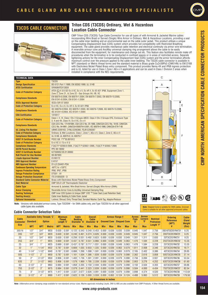
CMP
NORT
H AM
ERIC
AN S
PECI
FICA
TION
CAB
LE C
ONNE
CTOR
PRO
DUCT
S
154www.cmp-products.com
C A B L E G L A N D A N D C A B L E C O N N E C T I O N S P E C I A L I S T S CMP
CMP Triton CDS (T3CDS) Type Cable Connector for use all types of with Armored & Jacketed Marine cablesincorporating Wire Braid or Served (Single) Wire Armor in Ordinary, Wet & Hazardous Locations, providing a sealon the cable inner bedding and an environmental seal on the cable outer jacket. This product utilises a uniqueCompensating Displacement Seal (CDS) system which provides full compatibility with Restricted Breathingequipment. The cable gland provides mechanical cable retention and electrical continuity via armor wire termination.A reversible armour cone and AnyWay universal clamping ring arrangement allows the cable to be easilydisconnected from the equipment, for maintenance and change out etc. This feature also facilitates remote make offprocedures when the termination is to be conducted in confined spaces or in areas of restricted access. Separatetightening actions for the inner Compensating Displacement Seal (CDS) system and the armor termination affordsmaximum control over the pressure applied to the cable inner bedding. The T3CDS cable connector is available inNPT (standard) or Metric thread forms and the standard material is Brass grade CuZn39Pb3 (CW614N) to EN12168with Electroless Nickel Plated Brass entry component. This product provides Nema 4X and IP68 ingress protectionand is UL listed for use in Class I Zone I AEx e II applications and can be used in Class I Division 2 areas wheninstalled in compliance with the NEC requirements.
TECHNICAL DATAType T3CDSDesign Specification BS 6121:Part 1:1989, EN 50262:1999, UL 514BATEX Certification SIRA06ATEX1283X
Code of Protection Category ATEX II 2/3 GD Ex d IIC, Ex e II, Ex nR II, Ex tD A21 IP66, Equipment Zone 1,Zone 2, Zone 21, & Zone 22 - Gas Groups IIA, IIB, IIC
Compliance Standards EN 60079-0:2006, EN 60079-1:2004, EN 60079-7:2003, EN 60079-15:2005, EN 61241-0:2004, EN 61241-1:2004
IECEx Approval Number IECEx SIR 07.005XCode of Protection Category Ex d IIC, Ex e II, Ex nR II, Ex tD A21 IP66
Compliance Standards IEC 60079-0:2004, IEC 60079-1:2003, IEC 60079-7:2006, IEC 60079-15:2005, IEC 61241-0:2004, IEC 61241-1:2004
CSA Certification 1310517
Code of Protection Category Class I, II, III, Class I Div 2 Groups ABCD, Class II Div 2 Groups EFG, Enclosure Type3, 4 and 4X, Class III, Ex d IIC, Ex e II
Compliance Standards CSA C22.2 No. 174-M1984, CSA C22.2 No. 25-1966, CAN/CSA-C22.2 No. 18-92, CAN/CSA-C22.2 No. 94-M91, CAN/CSA-E60079-0-2001, IEC 60079-0 1998, CAN/CSA-E79-7-95
UL Listing File Number UBWE.E200163, CYMJ.E256366, FDJR.E256367Code of Protection Category Ordinary & Wet Locations, Class I, Zone 1, AEx e II, Class I, Zone 2, AEx e IICompliance Standards UL 514B, UL 60079-0, UL 60079-7GOST R Certificate Number POCC GB. 05.B01912Code of Protection Category Ex d IIC U / Ex e II UCompliance Standards P 52350.0-2005, P 52350.1-2005, P 52350.7-2005GGTN Permit Number PPC 00-18262GOST K Certificate Number KZ7500052.05.01.00063RoK Permit for Use Number 08-067693Lloyds Approval Number 01/00172DNV Approval Number E-6157ABS Approval Number 01-LD 234401-PDAContinuous Operating Temperature -60°C to +130°CIngress Protection Rating IP66, IP67, IP68Deluge Protection Compliance DTS01 : 91Deluge Protection Document ITS 01005029 - DStandard Cable Connector Material Brass with Electroless Nickel Plated Brass Entry ComponentSeal Material CMP SOLO LSF Thermoplastic Elastomer
Cable Type Armored & Jacketed, Wire Braid Armor, Served (Single) Wire Armor (SWA).
Armor Clamping Reversible Armor Cone & AnyWay Universal Clamping RingSealing Technique CMP Inner CDS System & Unique CMP "LRS" ™ Outer Seal (Load Retention Seal)Sealing Area(s) Cable Inner Bedding & Cable Outer JacketOptional Accessories Locknut, Shroud, Entry Thread Seal, Serrated Washer, Earth Tag, Adaptor/Reducer
Triton CDS (T3CDS) Ordinary, Wet & Hazardous Location Cable Connector T3CDS CABLE CONNECTOR
A
B
D
C
E
F
Note: †Alternative armor clamping range available for non-standard armour sizes. Marine approvals including Lloyds, DNV & ABS are also available from CMP Products. # Other thread forms are available.
Cable Connector Selection Table
L L U
OCTL
OCTL
OCTL
Note: Stepped Cone is suitable for SWA cables, GroovedCone is suitable for all other approved armoured cables
Note: Versions with dedicated armour cones, Type T3CDSW – for SWA cables only, and Type T3CDSX for all other approved cable types also available.
CableConnector
Size
Available Entry Threads ‘C’ Minimum Thread
Length ‘E’
CableBedding
Diameter ‘A’
Overall Cable
Diameter ‘B’
Armour Range † AcrossFlats‘D’
AcrossCorners
‘D’Nominal
ProtrusionLength ‘F’
OrderingReference
(NPT)#
CableGlandWeight(Ozs)
Standard Option Grooved Cone Stepped Cone
NPT NPT Metric NPT Metric Min Max Min Max Min Max Min Max Max Max
20S/16 1/2” 3/4” M20 0.630 0.591 0.122 0.343 0.240 0.453 0.000 0.039 0.035 0.039 0.945 1.047 2.756 20S16T3CDS1RA731 6.2520S 1/2” 3/4” M20 0.630 0.591 0.240 0.461 0.374 0.626 0.000 0.039 0.035 0.049 0.945 1.047 2.756 20ST3CDS1RA731 6.2520 1/2” 3/4” M20 0.630 0.591 0.256 0.551 0.492 0.823 0.000 0.039 0.035 0.049 1.201 1.311 2.835 20T3CDS1RA731 9.25
25S 3/4” 1” M25 0.669 0.591 0.437 0.787 0.551 0.866 0.000 0.039 0.049 0.063 1.476 1.594 3.228 25ST3CDS1RA732 13.3525 3/4” 1” M25 0.669 0.591 0.437 0.787 0.717 1.031 0.000 0.039 0.049 0.063 1.476 1.594 3.228 25T3CDS1RA732 13.3532 1” 1-1/4” M32 0.787 0.591 0.669 1.035 0.933 1.335 0.000 0.039 0.063 0.079 1.811 2.008 3.346 32T3CDS1RA733 19.7140 1-1/4” 1-1/2” M40 0.787 0.591 0.866 1.268 1.098 1.591 0.000 0.039 0.063 0.079 2.165 2.402 3.386 40T3CDS1RA734 29.85
50S 1-1/2” 2” M50 0.787 0.591 1.161 1.504 1.386 1.839 0.000 0.039 0.079 0.098 2.362 2.618 3.858 50ST3CDS1RA735 37.1450 2” 2-1/2” M50 0.906 0.591 1.402 1.736 1.591 2.091 0.000 0.039 0.079 0.098 2.756 3.094 3.937 50T3CDS1RA736 53.54
63S 2” 2-1/2” M63 0.906 0.591 1.579 1.969 1.795 2.339 0.000 0.039 0.079 0.098 2.953 3.276 4.252 63ST3CDS1RA736 61.6063 2-1/2” 3” M63 0.984 0.591 1.858 2.205 2.150 2.594 0.000 0.039 0.079 0.098 3.150 3.504 4.355 63T3CDS1RA737 59.86
75S 2-1/2” 3” M75 0.984 0.591 2.079 2.441 2.323 2.839 0.000 0.039 0.079 0.098 3.504 4.000 4.434 75ST3CDS1RA737 82.5475 3” 3-1/2” M75 1.417 0.591 2.327 2.677 2.626 3.091 0.000 0.039 0.079 0.098 3.898 4.374 4.520 75T3CDS1RA738 112.6490 3-1/2” 4” M90 1.417 0.591 2.622 3.126 3.000 3.559 0.000 0.063 0.124 0.124 4.488 5.063 5.512 90T3CDS1RA739 179.50
All dimensions in inches
L L U 05
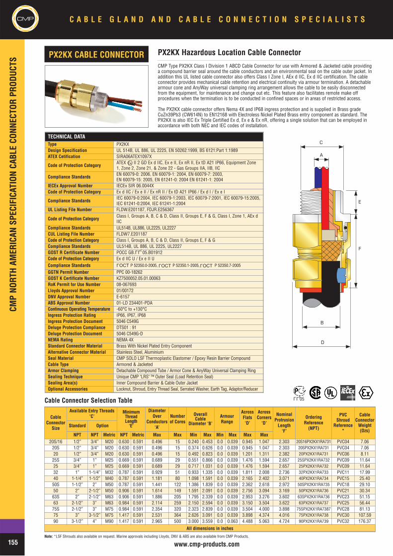
CMPCM
P NO
RTH
AMER
ICAN
SPE
CIFI
CATI
ON C
ABLE
CON
NECT
OR P
RODU
CTS
C A B L E G L A N D A N D C A B L E C O N N E C T I O N S P E C I A L I S T S
155 www.cmp-products.comNote: *LSF Shrouds also available on request. Marine approvals including Lloyds, DNV & ABS are also available from CMP Products.
TECHNICAL DATAType PX2KXDesign Specification UL 514B, UL 886, UL 2225, EN 50262:1999, BS 6121:Part 1:1989ATEX Cetification SIRA06ATEX1097X
Code of Protection Category ATEX II 2 GD Ex d IIC, Ex e II, Ex nR II, Ex tD A21 IP66, Equipment Zone1, Zone 2, Zone 21, & Zone 22 - Gas Groups IIA, IIB, IIC
Compliance Standards EN 60079-0: 2006, EN 60079-1: 2004, EN 60079-7: 2003, EN 60079-15: 2005, EN 61241-0: 2004 EN 61241-1: 2004
IECEx Approval Number IECEx SIR 06.0044XCode of Protection Category Ex d IIC / Ex e II / Ex nR II / Ex tD A21 IP66 / Ex d I / Ex e I
Compliance Standards IEC 60079-0:2004, IEC 60079-1:2003, IEC 60079-7:2001, IEC 60079-15:2005,IEC 61241-0:2004, IEC 61241-1:2004
UL Listing File Number FLDW.E201187, FDJR.E256367
Code of Protection Category Class I, Groups A, B, C & D, Class II, Groups E, F & G, Class I, Zone 1, AEx dIIC
Compliance Standards UL514B, UL886, UL2225, UL2227CUL Listing File Number FLDW7.E201187Code of Protection Category Class I, Groups A, B, C & D, Class II, Groups E, F & GCompliance Standards UL514B, UL 886, UL 2225, UL2227GOST R Certificate Number POCC GB. 05.B01912Code of Protection Category Ex d IIC U / Ex e II UCompliance Standards P 52350.0-2005, P 52350.1-2005, P 52350.7-2005
GGTN Permit Number PPC 00-18262GOST K Certificate Number KZ7500052.05.01.00063RoK Permit for Use Number 08-067693Lloyds Approval Number 01/00172DNV Approval Number E-6157ABS Approval Number 01-LD 234401-PDAContinuous Operating Temperature -60°C to +130°CIngress Protection Rating IP66, IP67, IP68Ingress Protection Document 5046 C549GDeluge Protection Compliance DTS01 : 91Deluge Protection Document 5046 C549G-DNEMA Rating NEMA 4XStandard Connector Material Brass With Nickel Plated Entry Component Alternative Connector Material Stainless Steel, AluminiumSeal Material CMP SOLO LSF Thermoplastic Elastomer / Epoxy Resin Barrier CompoundCable Type Armored & JacketedArmor Clamping Detachable Compound Tube / Armor Cone & AnyWay Universal Clamping RingSealing Technique Unique CMP "LRS" ™ Outer Seal (Load Retention Seal)Sealing Area(s) Inner Compound Barrier & Cable Outer JacketOptional Accessories Locknut, Shroud, Entry Thread Seal, Serrated Washer, Earth Tag, Adaptor/Reducer
CMP Type PX2KX Class I Division 1 ABCD Cable Connector for use with Armored & Jacketed cable providinga compound barrier seal around the cable conductors and an environmental seal on the cable outer jacket. Inaddition this UL listed cable connector also offers Class I Zone I, AEx d IIC, Ex d IIC certification. The cableconnector provides mechanical cable retention and electrical continuity via armour termination. A detachablearmour cone and AnyWay universal clamping ring arrangement allows the cable to be easily disconnectedfrom the equipment, for maintenance and change out etc. This feature also facilitates remote make offprocedures when the termination is to be conducted in confined spaces or in areas of restricted access.
The PX2KX cable connector offers Nema 4X and IP68 ingress protection and is supplied in Brass gradeCuZn39Pb3 (CW614N) to EN12168 with Electroless Nickel Plated Brass entry component as standard. ThePX2KX is also IEC Ex Triple Certified Ex d, Ex e & Ex nR, offering a single solution that can be employed inaccordance with both NEC and IEC codes of installation.
PX2KX Hazardous Location Cable ConnectorPX2KX CABLE CONNECTOR
A
B
D
C
E
F
Cable Connector Selection Table
L L U
CableConnector
Size
Available Entry Threads‘C’
MinimumThreadLength
‘E’
DiameterOver
Conductors‘A’
Numberof Cores
OverallCable
Diameter ‘B’
ArmourRange
AcrossFlats‘D’
AcrossCorners
‘D’
NominalProtrusion
Length‘F’
OrderingReference
(NPT)
PVCShroud
Reference*
CableConnector
Weight(Ozs)
Standard Option
NPT NPT Metric NPT Metric Max Max Min Max Min Max Max Max20S/16 1/2” 3/4” M20 0.630 0.591 0.496 15 0.240 0.453 0.0 0.039 0.945 1.047 2.303 20S16PX2KX1RA731 PVC04 7.06
20S 1/2” 3/4” M20 0.630 0.591 0.496 15 0.374 0.626 0.0 0.039 0.945 1.047 2.303 20SPX2KX1RA731 PVC04 7.0620 1/2” 3/4” M20 0.630 0.591 0.496 15 0.492 0.823 0.0 0.039 1.201 1.311 2.382 20PX2KX1RA731 PVC06 8.11
25S 3/4” 1” M25 0.669 0.591 0.689 29 0.551 0.866 0.0 0.039 1.476 1.594 2.657 25SPX2KX1RA732 PVC09 11.6425 3/4” 1” M25 0.669 0.591 0.689 29 0.717 1.031 0.0 0.039 1.476 1.594 2.657 25PX2KX1RA732 PVC09 11.6432 1” 1-1/4” M32 0.787 0.591 0.929 51 0.933 1.335 0.0 0.039 1.811 2.008 2.736 32PX2KX1RA733 PVC11 17.9940 1-1/4” 1-1/2” M40 0.787 0.591 1.181 80 1.098 1.591 0.0 0.039 2.165 2.402 3.071 40PX2KX1RA734 PVC15 25.40
50S 1-1/2” 2” M50 0.787 0.591 1.441 122 1.386 1.839 0.0 0.039 2.362 2.618 2.972 50SPX2KX1RA735 PVC18 29.1050 2” 2-1/2” M50 0.906 0.591 1.614 149 1.591 2.091 0.0 0.039 2.756 3.094 3.169 50PX2KX1RA736 PVC21 30.34
63S 2” 2-1/2” M63 0.906 0.591 1.886 205 1.795 2.339 0.0 0.039 2.953 3.276 3.602 63SPX2KX1RA736 PVC23 51.1563 2-1/2” 3” M63 0.984 0.591 2.114 259 2.150 2.594 0.0 0.039 3.150 3.504 3.622 63PX2KX1RA737 PVC25 56.44
75S 2-1/2” 3” M75 0.984 0.591 2.354 320 2.323 2.839 0.0 0.039 3.504 4.000 3.898 75SPX2KX1RA7387 PVC28 81.1375 3” 3-1/2” M75 1.417 0.591 2.531 364 2.626 3.091 0.0 0.039 3.898 4.374 4.016 75PX2KX1RA738 PVC30 107.5990 3-1/2” 4” M90 1.417 0.591 2.965 500 3.000 3.559 0.0 0.063 4.488 5.063 4.724 90PX2KX1RA739 PVC32 176.37
All dimensions in inches
L L U 05
OCTL
OCTL
OCTL
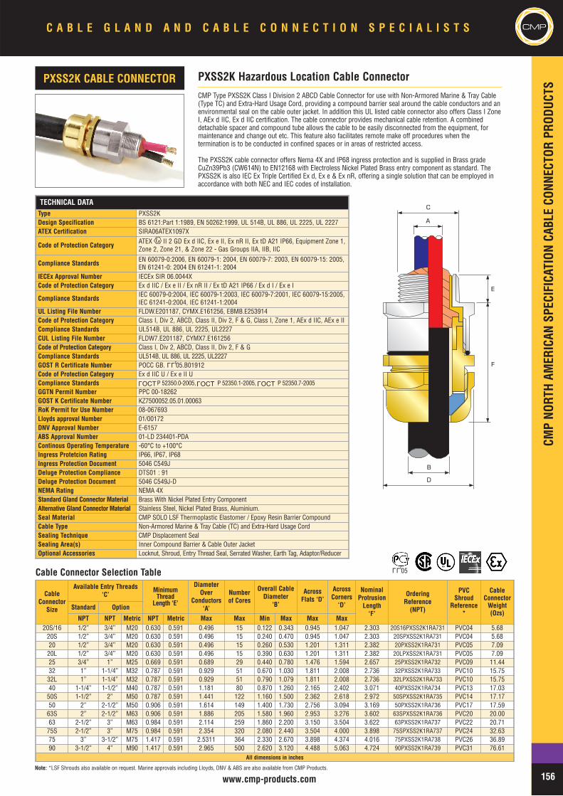
CMP
NORT
H AM
ERIC
AN S
PECI
FICA
TION
CAB
LE C
ONNE
CTOR
PRO
DUCT
S
CMPC A B L E G L A N D A N D C A B L E C O N N E C T I O N S P E C I A L I S T S
156www.cmp-products.comNote: *LSF Shrouds also available on request. Marine approvals including Lloyds, DNV & ABS are also available from CMP Products.
TECHNICAL DATAType PXSS2K Design Specification BS 6121:Part 1:1989, EN 50262:1999, UL 514B, UL 886, UL 2225, UL 2227ATEX Certification SIRA06ATEX1097X
Code of Protection Category ATEX II 2 GD Ex d IIC, Ex e II, Ex nR II, Ex tD A21 IP66, Equipment Zone 1,Zone 2, Zone 21, & Zone 22 - Gas Groups IIA, IIB, IIC
Compliance Standards EN 60079-0:2006, EN 60079-1: 2004, EN 60079-7: 2003, EN 60079-15: 2005, EN 61241-0: 2004 EN 61241-1: 2004
IECEx Approval Number IECEx SIR 06.0044XCode of Protection Category Ex d IIC / Ex e II / Ex nR II / Ex tD A21 IP66 / Ex d I / Ex e I
Compliance Standards IEC 60079-0:2004, IEC 60079-1:2003, IEC 60079-7:2001, IEC 60079-15:2005,IEC 61241-0:2004, IEC 61241-1:2004
UL Listing File Number FLDW.E201187, CYMX.E161256, EBMB.E253914Code of Protection Category Class I, Div 2, ABCD, Class II, Div 2, F & G, Class I, Zone 1, AEx d IIC, AEx e IICompliance Standards UL514B, UL 886, UL 2225, UL2227CUL Listing File Number FLDW7.E201187, CYMX7.E161256Code of Protection Category Class I, Div 2, ABCD, Class II, Div 2, F & GCompliance Standards UL514B, UL 886, UL 2225, UL2227GOST R Certificate Number POCC GB. 05.B01912Code of Protection Category Ex d IIC U / Ex e II UCompliance Standards P 52350.0-2005, P 52350.1-2005, P 52350.7-2005GGTN Permit Number PPC 00-18262GOST K Certificate Number KZ7500052.05.01.00063RoK Permit for Use Number 08-067693Lloyds approval Number 01/00172DNV Approval Number E-6157ABS Approval Number 01-LD 234401-PDAContinous Operating Temperature -60°C to +100°CIngress Protetcion Rating IP66, IP67, IP68Ingress Protection Document 5046 C549JDeluge Protection Compliance DTS01 : 91Deluge Protection Document 5046 C549J-DNEMA Rating NEMA 4XStandard Gland Connector Material Brass With Nickel Plated Entry ComponentAlternative Gland Connector Material Stainless Steel, Nickel Plated Brass, Aluminium.Seal Material CMP SOLO LSF Thermoplastic Elastomer / Epoxy Resin Barrier CompoundCable Type Non-Armored Marine & Tray Cable (TC) and Extra-Hard Usage CordSealing Technique CMP Displacement SealSealing Area(s) Inner Compound Barrier & Cable Outer JacketOptional Accessories Locknut, Shroud, Entry Thread Seal, Serrated Washer, Earth Tag, Adaptor/Reducer
CMP Type PXSS2K Class I Division 2 ABCD Cable Connector for use with Non-Armored Marine & Tray Cable(Type TC) and Extra-Hard Usage Cord, providing a compound barrier seal around the cable conductors and anenvironmental seal on the cable outer jacket. In addition this UL listed cable connector also offers Class I ZoneI, AEx d IIC, Ex d IIC certification. The cable connector provides mechanical cable retention. A combineddetachable spacer and compound tube allows the cable to be easily disconnected from the equipment, formaintenance and change out etc. This feature also facilitates remote make off procedures when thetermination is to be conducted in confined spaces or in areas of restricted access.
The PXSS2K cable connector offers Nema 4X and IP68 ingress protection and is supplied in Brass gradeCuZn39Pb3 (CW614N) to EN12168 with Electroless Nickel Plated Brass entry component as standard. ThePXSS2K is also IEC Ex Triple Certified Ex d, Ex e & Ex nR, offering a single solution that can be employed inaccordance with both NEC and IEC codes of installation.
CableConnector
Size
Available Entry Threads‘C’
MinimumThread
Length ‘E’
DiameterOver
Conductors‘A’
Numberof Cores
Overall CableDiameter
‘B’
AcrossFlats ‘D’
AcrossCorners
‘D’
NominalProtrusion
Length‘F’
OrderingReference
(NPT)
PVCShroud
Reference*
CableConnector
Weight(Ozs)
Standard Option
NPT NPT Metric NPT Metric Max Max Min Max Max Max20S/16 1/2” 3/4” M20 0.630 0.591 0.496 15 0.122 0.343 0.945 1.047 2.303 20S16PXSS2K1RA731 PVC04 5.68
20S 1/2” 3/4” M20 0.630 0.591 0.496 15 0.240 0.470 0.945 1.047 2.303 20SPXSS2K1RA731 PVC04 5.6820 1/2” 3/4” M20 0.630 0.591 0.496 15 0.260 0.530 1.201 1.311 2.382 20PXSS2K1RA731 PVC05 7.09
20L 1/2” 3/4” M20 0.630 0.591 0.496 15 0.390 0.630 1.201 1.311 2.382 20LPXSS2K1RA731 PVC05 7.0925 3/4” 1” M25 0.669 0.591 0.689 29 0.440 0.780 1.476 1.594 2.657 25PXSS2K1RA732 PVC09 11.4432 1” 1-1/4” M32 0.787 0.591 0.929 51 0.670 1.030 1.811 2.008 2.736 32PXSS2K1RA733 PVC10 15.75
32L 1” 1-1/4” M32 0.787 0.591 0.929 51 0.790 1.079 1.811 2.008 2.736 32LPXSS2K1RA733 PVC10 15.7540 1-1/4” 1-1/2” M40 0.787 0.591 1.181 80 0.870 1.260 2.165 2.402 3.071 40PXSS2K1RA734 PVC13 17.03
50S 1-1/2” 2” M50 0.787 0.591 1.441 122 1.160 1.500 2.362 2.618 2.972 50SPXSS2K1RA735 PVC14 17.1750 2” 2-1/2” M50 0.906 0.591 1.614 149 1.400 1.730 2.756 3.094 3.169 50PXSS2K1RA736 PVC17 17.59
63S 2” 2-1/2” M63 0.906 0.591 1.886 205 1.580 1.960 2.953 3.276 3.602 63SPXSS2K1RA736 PVC20 20.0063 2-1/2” 3” M63 0.984 0.591 2.114 259 1.860 2.200 3.150 3.504 3.622 63PXSS2K1RA737 PVC22 20.71
75S 2-1/2” 3” M75 0.984 0.591 2.354 320 2.080 2.440 3.504 4.000 3.898 75SPXSS2K1RA737 PVC24 32.6375 3” 3-1/2” M75 1.417 0.591 2.5311 364 2.330 2.670 3.898 4.374 4.016 75PXSS2K1RA738 PVC26 36.8990 3-1/2” 4” M90 1.417 0.591 2.965 500 2.620 3.120 4.488 5.063 4.724 90PXSS2K1RA739 PVC31 76.61
All dimensions in inches
PXSS2K Hazardous Location Cable ConnectorPXSS2K CABLE CONNECTOR
B
D
A
C
E
F
Cable Connector Selection Table
L L U
OCTL
OCTL
OCTL
L L U 05
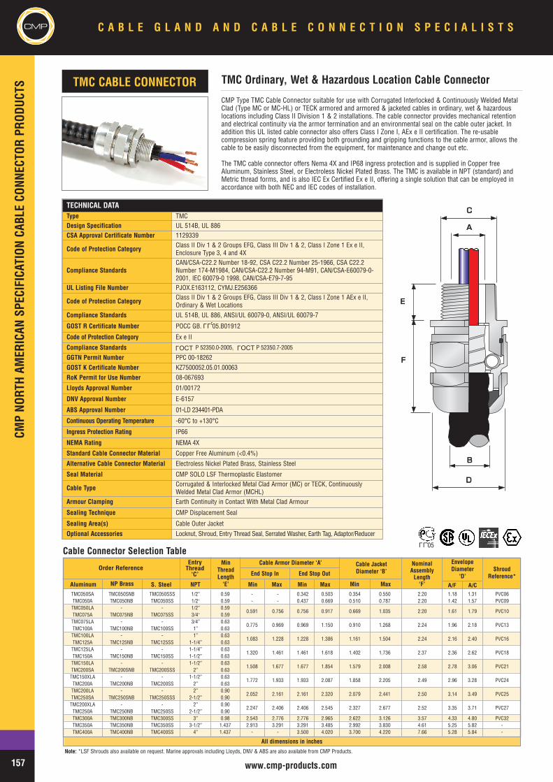
CMPCM
PNO
RTHAM
ERICAN
SPEC
IFICAT
IONCA
BLECO
NNEC
TORPR
ODUC
TSC A B L E G L A N D A N D C A B L E C O N N E C T I O N S P E C I A L I S T S
157 www.cmp-products.com
Note: *LSF Shrouds also available on request. Marine approvals including Lloyds, DNV & ABS are also available from CMP Products.
CMP Type TMC Cable Connector suitable for use with Corrugated Interlocked & Continuously Welded MetalClad (Type MC or MC-HL) or TECK armored and armored & jacketed cables in ordinary, wet & hazardouslocations including Class II Division 1 & 2 installations. The cable connector provides mechanical retentionand electrical continuity via the armor termination and an environmental seal on the cable outer jacket. Inaddition this UL listed cable connector also offers Class I Zone I, AEx e II certification. The re-usablecompression spring feature providing both grounding and gripping functions to the cable armor, allows thecable to be easily disconnected from the equipment, for maintenance and change out etc.
The TMC cable connector offers Nema 4X and IP68 ingress protection and is supplied in Copper freeAluminum, Stainless Steel, or Electroless Nickel Plated Brass. The TMC is available in NPT (standard) andMetric thread forms, and is also IEC Ex Certified Ex e II, offering a single solution that can be employed inaccordance with both NEC and IEC codes of installation.
TECHNICAL DATAType TMCDesign Specification UL 514B, UL 886CSA Approval Certificate Number 1129339
Code of Protection Category Class II Div 1 & 2 Groups EFG, Class III Div 1 & 2, Class I Zone 1 Ex e II,Enclosure Type 3, 4 and 4X
Compliance StandardsCAN/CSA-C22.2 Number 18-92, CSA C22.2 Number 25-1966, CSA C22.2Number 174-M1984, CAN/CSA-C22.2 Number 94-M91, CAN/CSA-E60079-0-2001, IEC 60079-0 1998, CAN/CSA-E79-7-95
UL Listing File Number PJOX.E163112, CYMJ.E256366
Code of Protection Category Class II Div 1 & 2 Groups EFG, Class III Div 1 & 2, Class I Zone 1 AEx e II,Ordinary & Wet Locations
Compliance Standards UL 514B, UL 886, ANSI/UL 60079-0, ANSI/UL 60079-7
GOST R Certificate Number POCC GB. 05.B01912
Code of Protection Category Ex e II
Compliance Standards P 52350.0-2005, P 52350.7-2005
GGTN Permit Number PPC 00-18262GOST K Certificate Number KZ7500052.05.01.00063RoK Permit for Use Number 08-067693
Lloyds Approval Number 01/00172
DNV Approval Number E-6157
ABS Approval Number 01-LD 234401-PDA
Continuous Operating Temperature -60°C to +130°C
Ingress Protection Rating IP66
NEMA Rating NEMA 4X
Standard Cable Connector Material Copper Free Aluminum (<0.4%)
Alternative Cable Connector Material Electroless Nickel Plated Brass, Stainless Steel
Seal Material CMP SOLO LSF Thermoplastic Elastomer
Cable Type Corrugated & Interlocked Metal Clad Armor (MC) or TECK, ContinuouslyWelded Metal Clad Armor (MCHL)
Armour Clamping Earth Continuity in Contact With Metal Clad Armour
Sealing Technique CMP Displacement Seal
Sealing Area(s) Cable Outer Jacket
Optional Accessories Locknut, Shroud, Entry Thread Seal, Serrated Washer, Earth Tag, Adaptor/Reducer
TMC Ordinary, Wet & Hazardous Location Cable ConnectorTMC CABLE CONNECTOR
AA
CC
EE
FF
DD
BB
Cable Connector Selection Table
Order ReferenceEntryThread‘C’
MinThreadLength‘E’
NominalAssemblyLength‘F’
EnvelopeDiameter
‘D’Shroud
Reference*
Cable Armor Diameter ‘A’ Cable JacketDiameter ‘B’
Aluminum NP Brass S. Steel NPT Min MaxMin Max Min Max
End Stop OutEnd Stop In
TMC050SA TMC050SNB TMC050SSS 1/2” 0.59 - - 0.342 0.503 0.354 0.550 2.20 1.18 1.31 PVC06TMC050A TMC050NB TMC050SS 1/2” 0.59 - - 0.437 0.669 0.510 0.787 2.20 1.42 1.57 PVC09TMC050LA - - 1/2” 0.59
0.591 0.756 0.756 0.917 0.669 1.035 2.20 1.61 1.79 PVC10TMC075A TMC075NB TMC075SS 3/4” 0.59TMC075LA - - 3/4” 0.63
0.775 0.969 0.969 1.150 0.910 1.268 2.24 1.96 2.18 PVC13TMC100A TMC100NB TMC100SS 1” 0.63TMC100LA - - 1” 0.63
1.083 1.228 1.228 1.386 1.161 1.504 2.24 2.16 2.40 PVC16TMC125A TMC125NB TMC125SS 1-1/4” 0.63TMC125LA - - 1-1/4” 0.63
1.320 1.461 1.461 1.618 1.402 1.736 2.37 2.36 2.62 PVC18TMC150A TMC150NB TMC150SS 1-1/2” 0.63TMC150LA - - 1-1/2” 0.63
1.508 1.677 1.677 1.854 1.579 2.008 2.58 2.78 3.06 PVC21TMC200SA TMC200SNB TMC200SSS 2” 0.63TMC150XLA - - 1-1/2” 0.63
1.772 1.933 1.933 2.087 1.858 2.205 2.49 2.96 3.28 PVC24TMC200A TMC200NB TMC200SS 2” 0.63TMC200LA - - 2” 0.90
2.052 2.161 2.161 2.320 2.079 2.441 2.50 3.14 3.49 PVC25TMC250SA TMC250SNB TMC250SSS 2-1/2” 0.90TMC200XLA - - 2” 0.90
2.247 2.406 2.406 2.545 2.327 2.677 2.52 3.35 3.71 PVC27TMC250A TMC250NB TMC250SS 2-1/2” 0.90TMC300A TMC300NB TMC300SS 3” 0.98 2.543 2.776 2.776 2.965 2.622 3.126 3.57 4.33 4.80 PVC32TMC350A TMC350NB TMC350SS 3-1/2” 1.437 2.913 3.291 3.291 3.485 2.992 3.830 4.61 5.25 5.82 -TMC400A TMC400NB TMC400SS 4” 1.437 - - 3.500 4.020 3.700 4.220 7.66 5.28 5.84 -
A/F A/C
LLU05
LLU
OCTL
OCTL
All dimensions in inches
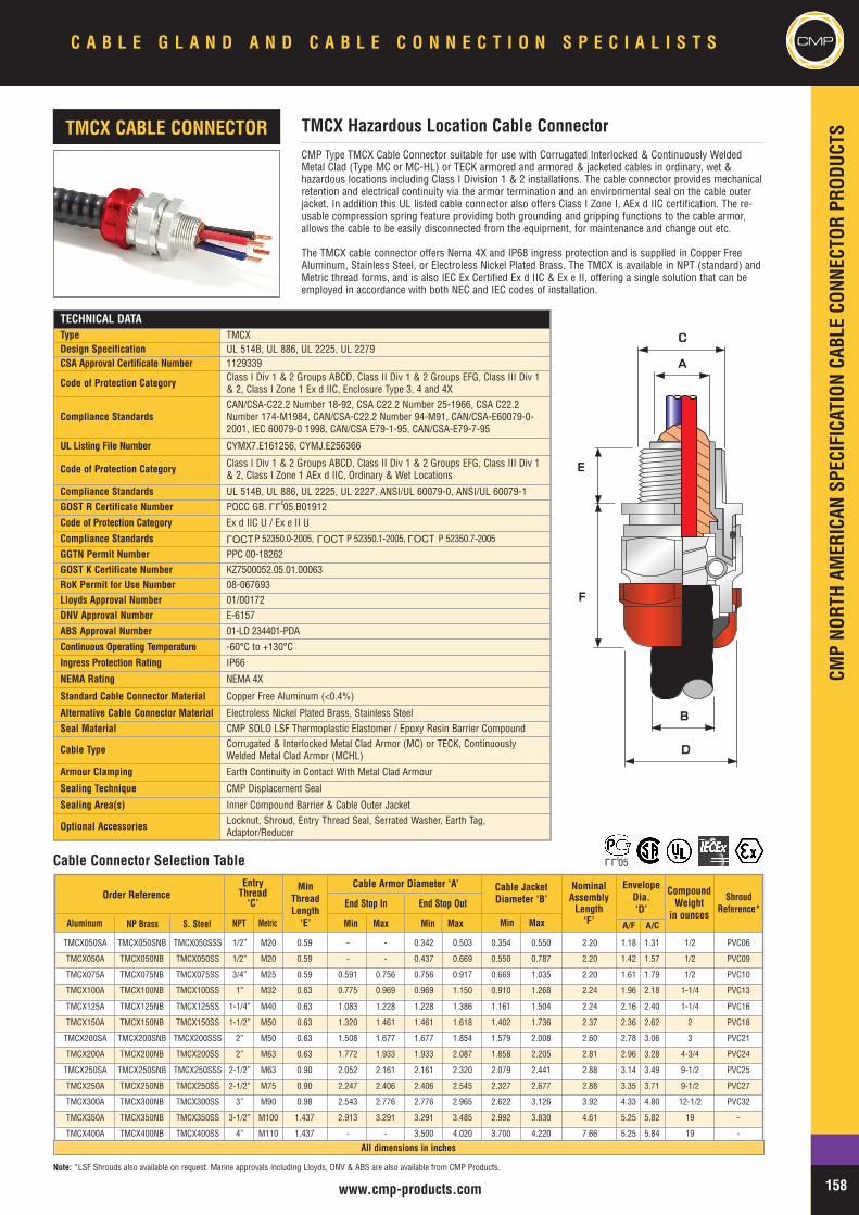
CMPNO
RTHAM
ERICAN
SPEC
IFICAT
IONCA
BLECO
NNEC
TORPR
ODUC
TS
CMPC A B L E G L A N D A N D C A B L E C O N N E C T I O N S P E C I A L I S T S
158www.cmp-products.com
Note: *LSF Shrouds also available on request. Marine approvals including Lloyds, DNV & ABS are also available from CMP Products.
CMP Type TMCX Cable Connector suitable for use with Corrugated Interlocked & Continuously WeldedMetal Clad (Type MC or MC-HL) or TECK armored and armored & jacketed cables in ordinary, wet &hazardous locations including Class I Division 1 & 2 installations. The cable connector provides mechanicalretention and electrical continuity via the armor termination and an environmental seal on the cable outerjacket. In addition this UL listed cable connector also offers Class I Zone I, AEx d IIC certification. The re-usable compression spring feature providing both grounding and gripping functions to the cable armor,allows the cable to be easily disconnected from the equipment, for maintenance and change out etc.
The TMCX cable connector offers Nema 4X and IP68 ingress protection and is supplied in Copper FreeAluminum, Stainless Steel, or Electroless Nickel Plated Brass. The TMCX is available in NPT (standard) andMetric thread forms, and is also IEC Ex Certified Ex d IIC & Ex e II, offering a single solution that can beemployed in accordance with both NEC and IEC codes of installation.
TECHNICAL DATAType TMCXDesign Specification UL 514B, UL 886, UL 2225, UL 2279CSA Approval Certificate Number 1129339
Code of Protection Category Class I Div 1 & 2 Groups ABCD, Class II Div 1 & 2 Groups EFG, Class III Div 1& 2, Class I Zone 1 Ex d IIC, Enclosure Type 3, 4 and 4X
Compliance StandardsCAN/CSA-C22.2 Number 18-92, CSA C22.2 Number 25-1966, CSA C22.2Number 174-M1984, CAN/CSA-C22.2 Number 94-M91, CAN/CSA-E60079-0-2001, IEC 60079-0 1998, CAN/CSA E79-1-95, CAN/CSA-E79-7-95
UL Listing File Number CYMX7.E161256, CYMJ.E256366
Code of Protection Category Class I Div 1 & 2 Groups ABCD, Class II Div 1 & 2 Groups EFG, Class III Div 1& 2, Class I Zone 1 AEx d IIC, Ordinary & Wet Locations
Compliance Standards UL 514B, UL 886, UL 2225, UL 2227, ANSI/UL 60079-0, ANSI/UL 60079-1GOST R Certificate Number POCC GB. 05.B01912
Code of Protection Category Ex d IIC U / Ex e II U
Compliance Standards P 52350.0-2005, P 52350.1-2005, P 52350.7-2005
GGTN Permit Number PPC 00-18262GOST K Certificate Number KZ7500052.05.01.00063RoK Permit for Use Number 08-067693Lloyds Approval Number 01/00172DNV Approval Number E-6157ABS Approval Number 01-LD 234401-PDA
Continuous Operating Temperature -60°C to +130°C
Ingress Protection Rating IP66
NEMA Rating NEMA 4X
Standard Cable Connector Material Copper Free Aluminum (<0.4%)
Alternative Cable Connector Material Electroless Nickel Plated Brass, Stainless SteelSeal Material CMP SOLO LSF Thermoplastic Elastomer / Epoxy Resin Barrier Compound
Cable Type Corrugated & Interlocked Metal Clad Armor (MC) or TECK, ContinuouslyWelded Metal Clad Armor (MCHL)
Armour Clamping Earth Continuity in Contact With Metal Clad Armour
Sealing Technique CMP Displacement Seal
Sealing Area(s) Inner Compound Barrier & Cable Outer Jacket
Optional Accessories Locknut, Shroud, Entry Thread Seal, Serrated Washer, Earth Tag,Adaptor/Reducer
TMCX Hazardous Location Cable ConnectorTMCX CABLE CONNECTOR
AA
CC
EE
FF
BB
DD
Cable Connector Selection Table
TMCX050SA TMCX050SNB TMCX050SSS 1/2” M20 0.59 - - 0.342 0.503 0.354 0.550 2.20 1.18 1.31 1/2 PVC06
TMCX050A TMCX050NB TMCX050SS 1/2” M20 0.59 - - 0.437 0.669 0.550 0.787 2.20 1.42 1.57 1/2 PVC09
TMCX075A TMCX075NB TMCX075SS 3/4” M25 0.59 0.591 0.756 0.756 0.917 0.669 1.035 2.20 1.61 1.79 1/2 PVC10
TMCX100A TMCX100NB TMCX100SS 1” M32 0.63 0.775 0.969 0.969 1.150 0.910 1.268 2.24 1.96 2.18 1-1/4 PVC13
TMCX125A TMCX125NB TMCX125SS 1-1/4” M40 0.63 1.083 1.228 1.228 1.386 1.161 1.504 2.24 2.16 2.40 1-1/4 PVC16
TMCX150A TMCX150NB TMCX150SS 1-1/2” M50 0.63 1.320 1.461 1.461 1.618 1.402 1.736 2.37 2.36 2.62 2 PVC18
TMCX200SA TMCX200SNB TMCX200SSS 2” M50 0.63 1.508 1.677 1.677 1.854 1.579 2.008 2.60 2.78 3.06 3 PVC21
TMCX200A TMCX200NB TMCX200SS 2” M63 0.63 1.772 1.933 1.933 2.087 1.858 2.205 2.81 2.96 3.28 4-3/4 PVC24
TMCX250SA TMCX250SNB TMCX250SSS 2-1/2” M63 0.90 2.052 2.161 2.161 2.320 2.079 2.441 2.88 3.14 3.49 9-1/2 PVC25
TMCX250A TMCX250NB TMCX250SS 2-1/2” M75 0.90 2.247 2.406 2.406 2.545 2.327 2.677 2.88 3.35 3.71 9-1/2 PVC27
TMCX300A TMCX300NB TMCX300SS 3” M90 0.98 2.543 2.776 2.776 2.965 2.622 3.126 3.92 4.33 4.80 12-1/2 PVC32
TMCX350A TMCX350NB TMCX350SS 3-1/2” M100 1.437 2.913 3.291 3.291 3.485 2.992 3.830 4.61 5.25 5.82 19 -
TMCX400A TMCX400NB TMCX400SS 4” M110 1.437 - - 3.500 4.020 3.700 4.220 7.66 5.25 5.84 19 -
Order ReferenceEntryThread‘C’
MinThreadLength‘E’
NominalAssemblyLength‘F’
EnvelopeDia.‘D’
CompoundWeight
in ounces
ShroudReference*
Cable Armor Diameter ‘A’ Cable JacketDiameter ‘B’
Aluminum NP Brass S. Steel NPT Metric Min MaxMin Max Min Max
End Stop OutEnd Stop In
A/F A/C
LLU05
LLU
OCTL
OCTL
OCTL
All dimensions in inches
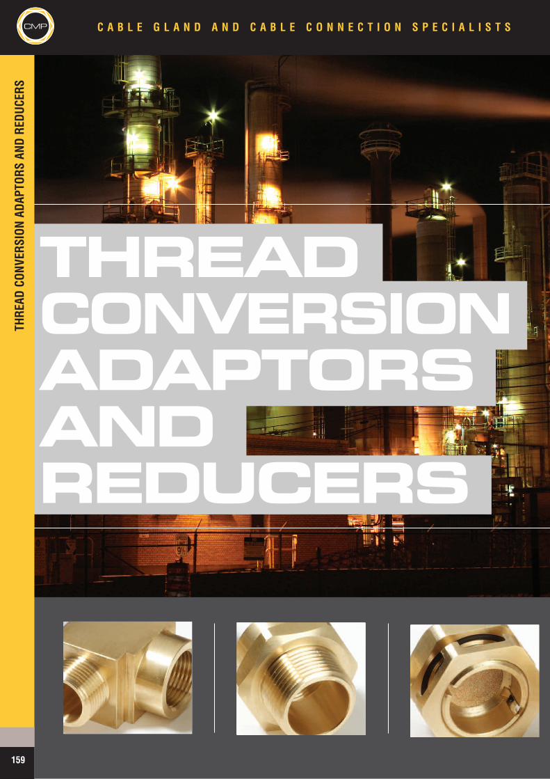
CMPTH
READ
CONV
ERSION
ADAP
TORS
ANDRE
DUCE
RSC A B L E G L A N D A N D C A B L E C O N N E C T I O N S P E C I A L I S T S
159
THREADCONVERSIONADAPTORSANDREDUCERS
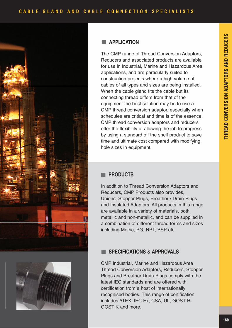
APPLICATION
The CMP range of Thread Conversion Adaptors,Reducers and associated products are availablefor use in Industrial, Marine and Hazardous Areaapplications, and are particularly suited toconstruction projects where a high volume ofcables of all types and sizes are being installed.When the cable gland fits the cable but itsconnecting thread differs from that of theequipment the best solution may be to use aCMP thread conversion adaptor, especially whenschedules are critical and time is of the essence.CMP thread conversion adaptors and reducersoffer the flexibility of allowing the job to progressby using a standard off the shelf product to savetime and ultimate cost compared with modifyinghole sizes in equipment.
PRODUCTS
In addition to Thread Conversion Adaptors andReducers, CMP Products also provides,Unions, Stopper Plugs, Breather / Drain Plugsand Insulated Adaptors. All products in this rangeare available in a variety of materials, bothmetallic and non-metallic, and can be supplied ina combination of different thread forms and sizesincluding Metric, PG, NPT, BSP etc.
SPECIFICATIONS & APPROVALS
CMP Industrial, Marine and Hazardous AreaThread Conversion Adaptors, Reducers, StopperPlugs and Breather Drain Plugs comply with thelatest IEC standards and are offered withcertification from a host of internationallyrecognised bodies. This range of certificationincludes ATEX, IEC Ex, CSA, UL, GOST R.GOST K and more.
THRE
ADCO
NVER
SION
ADAP
TORS
ANDRE
DUCE
RS
CMP
160
C A B L E G L A N D A N D C A B L E C O N N E C T I O N S P E C I A L I S T S
CMPTH
READ
CONV
ERSION
ADAP
TORS
ANDRE
DUCE
RSC A B L E G L A N D A N D C A B L E C O N N E C T I O N S P E C I A L I S T S
161 www.cmp-products.com
ORDERING DEFINITIONS (HOW TO ORDER)
DescriptionAllenkey
recess
Metallic Non-Metallic
Ex ‘d’ Ex ‘e’ Industrial Ex ‘e’ Industrial
747 RecessedNon-TamperProof Type ‘A’
� � � � � �
747 RecessedTamper Proof
Type ‘B’
�� � � � �
757Hexagon Head � � � � � �
757Hexagon Head
c/w ‘O’ ring seal (*)� � � � � �
767Dome Head
� � � � � �
767Dome Head
c/w ‘O’ ring seal (*)� � � � � �
Code Form of ProtectionD Dual Certified Ex ‘d’ / Ex ‘e’E Increased Safety Ex ‘e’F Flameproof Ex ‘d’G General Purpose IndustrialM Group 1 Mining (Ex ‘d’)U UL Listed - Hazardous LocationsC CSA Approved - Ex d / Ex e
Code Options
A Externally Secured - Non Tamper ProofEx ‘d’ Stopper Plug (Type A)
B Internally Secured - Tamper ProofEx ‘d’ Stopper Plug (Type B)
R Optional ‘O’ ring
Code Thread FormM Metric
N NPSM
T NPT
P PG
B BSPP
I E.T. (Imperial)
S BSPT
Code Material- Brass
1 Aluminium
2 Nylon
3 Mild Steel
4 Stainless Steel
5 Nickel Plated Brass
CodeThread Size
Metric‘M’
NPSM‘N’
NPT‘T’
PG‘P’
BSP‘B’
Imperial‘I’
BSP‘S’
1A - - - 7 - - -
1 16 1/2” 1/2” 9 1/2” 5/8” 1/2”
2 20 3/4” 3/4” 11 3/4” 3/4” 3/4”
3 25 1” 1” 13.5 1” 1” 1”
4 32 1-1/4” 1-1/4” 16 1-1/4” 1-1/4” 1-1/4”
5 40 1-1/2” 1-1/2” 21 1-1/2” 1-1/2” 1-1/2”
6 50 2” 2” 29 2” 2” 2”
7 63 2-1/2” 2-1/2” 36 2-1/2” 2-1/2” 2-1/2”
8 75 3” 3” 42 3” 3” 3”
9 90 3 1/2” 3 1/2” 48 3 1/2” 3-1/2” 3 1/2”
10 100 4” 4” - 4” 4” 4”
KEY TO ORDERING REFERENCES FOR ADAPTORS, REDUCERS & STOPPER PLUGS
Other variations available on request
HOW TO ORDER - To determine ordering reference please select from the tables below in the following fashion :-Form of protection - Option (if required) - Thread Form - Thread Size - Material
Table A
Table B
Table C
Table D
Stopper Plug Options
Table E
FromIndex
Opposite
FromTable Abelow
FromTable Bbelow
FromTable Cbelow
FromTable Dbelow
FromTable Ebelow
757 E R M 2 5
ProductType
Form ofProtection
Options ThreadForm
ThreadSize Material
E - X - A - M - P - L - E
When selecting and installing certified electrical equipment and components in potentially explosive atmospheres, it is the users responsibility toensure that the local industry codes of practice are observed and followed, for example EN 60079-14, IEC 60079-14, or NFPA 70 / NEC 500.
Notes: Nominal dimensions shown in this catalogue may vary due to material availability. All dimensions shown are in millimetres unlessotherwise stated. Within the parameters of its hazardous area certification CMP products reserves the right to change the design and / ordimensions of any of the products illustrated without notice. For further information please contact CMP Products.
CMP Products Terms & Conditions will apply to all sales orders unless otherwise contractually agreed. These can be obtained form CMP offices oronline at www.cmp-products.com
Note * This option is available only with parallel thread Stopper Plugs

THRE
ADCO
NVER
SION
ADAP
TORS
ANDRE
DUCE
RS
CMPC A B L E G L A N D A N D C A B L E C O N N E C T I O N S P E C I A L I S T S
162www.cmp-products.com
781SERIESBreather/Drain Plugs
Technical Data
Type 781
Design Specification BS 6121: Part 1: 1989.
ATEX Certification Detail SIRA 01 ATEX 1284U
Code of Protection Category ATEX II 2 GD Ex e II Component, Zone 1, Zone 2, Zone 21, & Zone 22 - Gas Groups IIA, IIB, IIC
IECEx Certification Detail IECEx SIR07.0054U
Code of Protection Category Ex e II / Ex tD A21 IP6X
Compliance Standards EN 60079-0, EN 60079-7, EN 61241-1, IEC 60079-0, IEC 60079-7, IEC 61241-1
Continous Operating Temperature -60°C to +200°C
Ingress Protection Rating IP66 (When fitted in a bottom entry, perpendicular manner)
Materials Brass, Nickel Plated Brass, Aluminium, Stainless Steel, Nylon
Accessories Included Integral Entry Thread ‘O’ Ring Seal, Castellated Locknut
Marked with ATEX certification details as standard. Alternative certification marking shown in the table below can be applied if requested at the time of ordering.
Product Selection Table *OrderingReference
ThreadSize
MinimumThread Length Protrusion Height Across Flats
DimensionAcross CornersDimensions
InstallationTorque (Nm)
781EM2 M20 X 1.5 15 18.0 30.0 33.0 7
781EM3 M25 X 1.5 15 17.0 31.5 35.0 10
781ET1 1/2” NPT 15 18.0 30.0 33.0 7
781ET2 3/4” NPT 15 17.0 31.5 35.0 10
All dimensions shown are in millimetres unless otherwise stated
Additional Approvals
GOST Ex Approval Certificate POCC GB. 05.B01367, POCC GB. 05.B01369
CSA Approval Certificate 1055233 Ex e II, IP66
Note * Please refer to ordering guide tables on page 161 for reference definitions, denoting material variants
Breather / Drain Plug Type 781 with increased Safety Ex e II form of protection.
The CMP Type 781 Breather / Drain Plug is designed for Increased Safety Ex e apparatus that is susceptible to condensation or prone to moisture collection or ingressduring normal operation. The Type 781 is designed to act as both a drainage device, when mounted in a bottom entry of the equipment, and also to enable the inside air tobreathe with the external environment under normal ambient and atmospheric conditions, whilst excluding further dust and moisture from penetrating the enclosure. TheType 781 Breather / Drain Plug is supplied complete with an integral entry thread ‘O’ ring seal, and a castellated locknut to facilitate drainage from inside the enclosure. AGeneral Purpose Industrial version is also available.
Metallic Breather / Drain Plugs are available in Brass, Aluminium or Stainless Steel and can be supplied for both Industrial and Hazardous Area applications, with Ex eComponent Approval.
Other thread forms (equivalent to metric sizes M20 and M25 only), including PG, BSPP, NPSM and Imperial (ET) available on request. Please refer to Table D on page 161for further information on these options.
• Filter prevents any dirt or other foreign bodies from entering the enclosure
• Breathing capabilities help to combat the build up of moisture andpotential condensation in the apparatus.
• Slotted Entry Threads and Castellated Locknut allows excess waterto flow into inverted drain device.
• Draining features enable release of any water that has penetrated theapparatus whilst maintaining the Increased Safety form of protection.
• Integral ‘O’ Ring ensures an effective seal at the interface between theBreather/Drain device and the equipment.
Castellated LocknutSlotted Arrangement
‘O’ Ring
Filter
Drainage Hole
ProtrusionHeight
LLU LLU
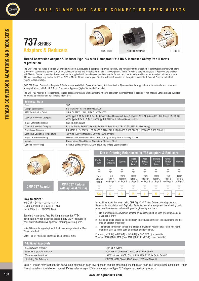
CMPTH
READ
CONV
ERSION
ADAP
TORS
ANDRE
DUCE
RSC A B L E G L A N D A N D C A B L E C O N N E C T I O N S P E C I A L I S T S
163 www.cmp-products.com
737SERIESAdaptors & Reducers
HOW TO ORDER *e.g. 737 – D – M – 2 – M – 3 - 4= Dual Certified Ex d & Ex e – M20(M) x M25 (F) - Stainless Steel.
It should be noted that when using CMP Type 737 Thread Conversion Adaptors andReducers in association with Explosion Protected electrical equipment the following basicrules must be observed in line with good engineering practice:-
1. No more than one conversion adaptor or reducer should be used at one time on anygiven cable entry.
2. Stopping plugs should be fitted directly into unused entries of the equipment, and notinto an adaptor or reducer.
3. The female connection thread of a Thread Conversion Adaptor shall ‘step’ not morethan one ‘size’ up in the case of a thread gender change.
Example ; M20 (M) to M25 (F) or M20 (M) to 3/4” NPT (f) is permittedWhere as M20 (M) to M32 (F) or M20 (M) to 1” NPT (F) is not permitted
Additional ApprovalsIEC Approval Certificate SIRA 05 Y 1089U
GOST Ex Approval Certificate POCC GB. O5.BO1367, POCC GB. 05.BO1369
CSA Approval Certificate 1055233 Class I ABCD, Class II EFG, IP68 TYPE 4X Ex d / Ex e IIC
UL Listing File Reference EBNV.E214221 Class I ABCD, Class II EFG and Class III
Thread Conversion Adaptor & Reducer Type 737 with Flameproof Ex d IIC & Increased Safety Ex e II formsof protection.
The CMP Type 737 range of Thread Conversion Adaptors & Reducers is designed to provide flexibility and versatility in the execution of construction works when thereis a conflict between the type or size of the cable gland thread and the cable entry hole in the equipment. These Thread Conversion Adaptors & Reducers are availablewith Male to Female connection threads and can be supplied with thread conversion between the forward and rear threads to either an increased or reduced size or adifferent thread type, e.g. Metric to NPT, or NPT to Metric. Please refer to page 161 for further infromation on the options available. A General Purpose Industrialversion is also available.
CMP 737 Thread Conversion Adaptors & Reducers are available in Brass, Aluminium, Stainless Steel or Nylon and can be supplied for both Industrial and HazardousArea applications, with Ex ‘d’ & Ex ‘e’ Component Approval (Nylon Version is Ex e only).
The CMP 737 Adaptor & Reducer range is also optionally available with an integral ‘O’ Ring seal when the male thread is parallel. A non-metallic version is also availableon request to complement non metallic enclosures.
Note * : Please refer to the thread conversion options on page 164 opposite and the ordering guide tables on page 161 for reference definitions. OtherThread Variations available on request. Please refer to page 165 for dimensions of type 737 adaptor and reducer products.
Standard Hazardous Area Marking Includes for ATEXcertification. When ordering please notify CMP Products inyour order if alternative approval markings are required.
Note: When ordering Adaptors & Reducers always state the MaleThread size first.
Note: The ‘O’ ring detail illustrated is an optional extra.
CMP 737 AdaptorCMP 737 Reducer
with optional ‘O’ ring
FromIndex onPage 1
FromTable A
on Page 2
FromTable B
on Page 2
FromTable C
on Page 2
FromTable Don Page 2
FromTable C
on Page 2
737 D R M 3 M
ProductType
Form ofProtection
OptionsMaleThreadForm
MaleThreadSize
FemaleThreadForm
Key to Ordering References for 737 Adaptors & Reducers
FromTable Don Page 2
FromTable E
on Page 2
2 4
FemaleThreadSize
Material
ADAPTOR NYLON ADAPTOR REDUCER
Technical DataType 737
Design Specification BS 6121: Part 1: 189, EN 50262:1999
ATEX Certification Detail SIRA O1 ATEX 1284U, SIRA O1 ATEX 1003
Code of Protection CategoryATEX II 2 GD Ex d IIC & Ex e II, Component and Equipment, Zone 1, Zone 2, Zone 21, & Zone 22 - Gas Groups IIA, IIB, IICATEX IM 2 Ex d I & Ex e I. ATEX II 2 GD Ex e II only on Nylon version.
IECEx Certification Detail IECEx SIR07.0052U
Code of Protection Category Ex d I / Ex e I / Ex d IIC / Ex e II / Ex tD A21 IP6X (Ex e II / Ex tD A21 IP6X for Nylon only)Compliance Standards EN 60079-0, EN 60079-1, EN 60079-7, EN 61241-1, IEC 60079-0, IEC 60079-1, IEC60079-7, IEC 61241-1
Continous Operating Temperature -60°C to +200°C (Metallic), -20°C to +60°C (Nylon)
Ingress Protection Rating IP66 or IP68 when fitted with a CMP ‘O’ Ring or Entry Thread Sealing Washer
Materials Brass, Nickel Plated Brass, Aluminium, Stainless Steel
Optional Accessories Locknut, Serrated Washer, Earth Tag, Entry Thread Sealing Washer
LLU LLU
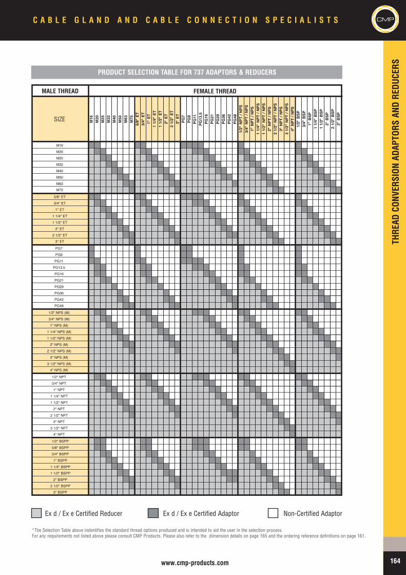
THRE
ADCO
NVER
SION
ADAP
TORS
ANDRE
DUCE
RS
164www.cmp-products.com
SIZE M16
M20
M25
M32
M40
M50
M63
M75
5/8"E
T3/4
"ET
1"ET
11/4
"ET
11/2
"ET
2"ET
21/2
"ET
3"ET
PG7
PG9
PG11
PG13
.5PG
16PG
21PG
29PG
36PG
42PG
481/2
"NPT
/NPS
3/4"N
PT/N
PS1"
NPT
/NPS
11/4
"NPT
/NPS
11/2
"NPT
/NPS
2"NP
T/N
PS2
1/2"N
PT/N
PS3"
NPT
/NPS
31/2
"NPT
/NPS
4"NP
T/N
PS1/2
"BSP
3/4"B
SP1"
BSP
11/4
"BSP
11/2
"BSP
2"BS
P2
1/2"B
SP3"
BSP
M16M20M25M32M40M50M63M75
5/8" ET3/4" ET1" ET1 1/4" ET1 1/2" ET2" ET2 1/2" ET3" ET
PG7PG9PG11PG13.5PG16PG21PG29PG36PG42PG48
1/2" NPS (M)3/4" NPS (M)1" NPS (M)1 1/4" NPS (M)1 1/2" NPS (M)2" NPS (M)2 1/2" NPS (M)3" NPS (M)3 1/2" NPS (M)4" NPS (M)
1/2" NPT3/4" NPT1" NPT1 1/4" NPT1 1/2" NPT2" NPT2 1/2" NPT3" NPT3 1/2" NPT4" NPT
1/2" BSPP5/8" BSPP3/4" BSPP1" BSPP1 1/4" BSPP1 1/2" BSPP2" BSPP2 1/2" BSPP3" BSPP
Ex d / Ex e Certified Reducer Ex d / Ex e Certified Adaptor Non-Certified Adaptor
*The Selection Table above indentifies the standard thread options produced and is intended to aid the user in the selection process.For any requirements not listed above please consult CMP Products. Please also refer to the dimension details on page 165 and the ordering reference definitions on page 161.
PRODUCT SELECTION TABLE FOR 737 ADAPTORS & REDUCERS
MALE THREAD FEMALE THREADMALE THREAD FEMALE THREAD
C A B L E G L A N D A N D C A B L E C O N N E C T I O N S P E C I A L I S T S CMP
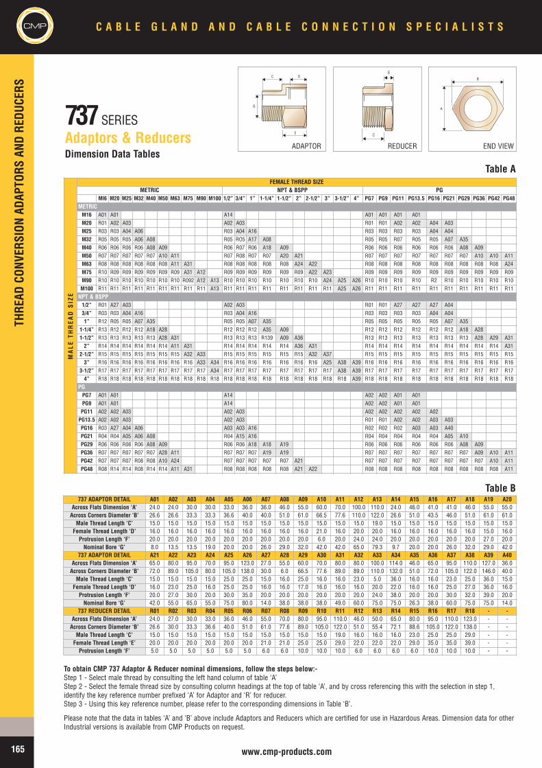
D
E
C
G
B
A
C
E
CMPTH
READ
CONV
ERSION
ADAP
TORS
ANDRE
DUCE
RSC A B L E G L A N D A N D C A B L E C O N N E C T I O N S P E C I A L I S T S
165 www.cmp-products.com
737SERIESAdaptors & Reducers
Table ADimension Data Tables
Table B737 ADAPTOR DETAIL A01 A02 A03 A04 A05 A06 A07 A08 A09 A10 A11 A12 A13 A14 A15 A16 A17 A18 A19 A20
Across Flats Dimension ‘A’ 24.0 24.0 30.0 30.0 33.0 36.0 36.0 46.0 55.0 60.0 70.0 100.0 110.0 24.0 46.0 41.0 41.0 46.0 55.0 55.0Across Corners Diameter ‘B’ 26.6 26.6 33.3 33.3 36.6 40.0 40.0 51.0 61.0 66.5 77.6 110.0 122.0 26.6 51.0 43.5 46.0 51.0 61.0 61.0
Male Thread Length ‘C’ 15.0 15.0 15.0 15.0 15.0 15.0 15.0 15.0 15.0 15.0 15.0 15.0 19.0 15.0 15.0 15.0 15.0 15.0 15.0 15.0Female Thread Length ‘D’ 16.0 16.0 16.0 16.0 16.0 16.0 16.0 16.0 16.0 21.0 16.0 20.0 20.0 16.0 16.0 16.0 16.0 16.0 15.0 16.0
Protrusion Length ‘F’ 20.0 20.0 20.0 20.0 20.0 20.0 20.0 20.0 20.0 6.0 20.0 24.0 24.0 20.0 20.0 20.0 20.0 20.0 27.0 20.0Nominal Bore ‘G’ 8.0 13.5 13.5 19.0 20.0 20.0 26.0 29.0 32.0 42.0 42.0 65.0 79.3 9.7 20.0 20.0 26.0 32.0 29.0 42.0
737 ADAPTOR DETAIL A21 A22 A23 A24 A25 A26 A27 A28 A29 A30 A31 A32 A33 A34 A35 A36 A37 A38 A39 A40Across Flats Dimension ‘A’ 65.0 80.0 95.0 70.0 95.0 123.0 27.0 55.0 60.0 70.0 80.0 80.0 100.0 114.0 46.0 65.0 95.0 110.0 127.0 36.0Across Corners Diameter ‘B’ 72.0 89.0 105.0 80.0 105.0 138.0 30.0 6.0 66.5 77.6 89.0 89.0 110.0 132.0 51.0 72.0 105.0 122.0 146.0 40.0
Male Thread Length ‘C’ 15.0 15.0 15.0 15.0 25.0 25.0 15.0 16.0 25.0 16.0 16.0 23.0 5.0 36.0 16.0 16.0 23.0 25.0 36.0 15.0Female Thread Length ‘D’ 16.0 23.0 25.0 16.0 25.0 25.0 16.0 16.0 17.0 16.0 16.0 16.0 20.0 22.0 16.0 16.0 25.0 27.0 36.0 16.0
Protrusion Length ‘F’ 20.0 27.0 30.0 20.0 30.0 35.0 20.0 20.0 20.0 20.0 20.0 20.0 24.0 38.0 20.0 20.0 30.0 32.0 39.0 20.0Nominal Bore ‘G’ 42.0 55.0 65.0 55.0 75.0 80.0 14.0 38.0 38.0 38.0 49.0 60.0 75.0 75.0 26.3 38.0 60.0 75.0 75.0 14.0
737 REDUCER DETAIL R01 R02 R03 R04 R05 R06 R07 R08 R09 R10 R11 R12 R13 R14 R15 R16 R17 R18 - -Across Flats Dimension ‘A’ 24.0 27.0 30.0 33.0 36.0 46.0 55.0 70.0 80.0 95.0 110.0 46.0 50.0 65.0 80.0 95.0 110.0 123.0 - -Across Corners Diameter ‘B’ 26.6 30.0 33.3 36.6 40.0 51.0 61.0 77.6 89.0 105.0 122.0 51.0 55.4 72.1 88.6 105.0 122.0 138.0 - -
Male Thread Length ‘C’ 15.0 15.0 15.0 15.0 15.0 15.0 15.0 15.0 15.0 15.0 19.0 16.0 16.0 16.0 23.0 25.0 25.0 29.0 - -Female Thread Length ‘E’ 20.0 20.0 20.0 20.0 20.0 20.0 21.0 21.0 25.0 25.0 29.0 22.0 22.0 22.0 29.0 35.0 35.0 39.0 - -
Protrusion Length ‘F’ 5.0 5.0 5.0 5.0 5.0 5.0 6.0 6.0 10.0 10.0 10.0 6.0 6.0 6.0 6.0 10.0 10.0 10.0 - -
To obtain CMP 737 Adaptor & Reducer nominal dimensions, follow the steps below:-Step 1 - Select male thread by consulting the left hand column of table ‘A’Step 2 - Select the female thread size by consulting column headings at the top of table ‘A’, and by cross referencing this with the selection in step 1,identify the key reference number prefixed ‘A’ for Adaptor and ‘R’ for reducer.Step 3 - Using this key reference number, please refer to the corresponding dimensions in Table ‘B’.
Please note that the data in tables ‘A’ and ‘B’ above include Adaptors and Reducers which are certified for use in Hazardous Areas. Dimension data for otherIndustrial versions is available from CMP Products on request.
ADAPTOR END VIEWREDUCER
FEMALE THREAD SIZEMETRIC NPT & BSPP PG
MI6 M20 M25 M32 M40 M50 M63 M75 M90 M100 1/2” 3/4” 1” 1-1/4” 1-1/2” 2” 2-1/2” 3” 3-1/2” 4” PG7 PG9 PG11 PG13.5 PG16 PG21 PG29 PG36 PG42 PG48METRICM16 A01 A01 A14 A01 A01 A01 A01M20 R01 A02 A03 A02 A03 R01 R01 A02 A02 A04 A03M25 R03 R03 A04 A06 R03 A04 A16 R03 R03 R03 R03 A04 A04M32 R05 R05 R05 A06 A08 R05 RO5 A17 A08 R05 R05 R07 R05 R05 A07 A35M40 R06 R06 R06 R06 A08 A09 R06 R07 R06 A18 A09 R06 R06 R06 R06 R06 R06 A08 A09M50 R07 R07 R07 R07 R07 A10 A11 R07 R08 R07 R07 A20 A21 R07 R07 R07 R07 R07 R07 R07 A10 A10 A11M63 R08 R08 R08 R08 R08 R08 A11 A31 R08 R08 R08 R08 R08 A24 A22 R08 R08 R08 R08 R08 R08 R08 R08 R08 A24M75 R10 R09 R09 R09 R09 R09 R09 A31 A12 R09 R09 R09 R09 R09 R09 A22 A23 R09 R09 R09 R09 R09 R09 R09 R09 R09 R09M90 R10 R10 R10 R10 R10 R10 R10 R092 A12 A13 R10 R10 R10 R10 R10 R10 R10 A24 A25 A26 R10 R10 R10 R10 R2 R10 R10 R10 R10 R10M100 R11 R11 R11 R11 R11 R11 R11 R11 R11 A13 R11 R11 R11 R11 R11 R11 R11 R11 A25 A26 R11 R11 R11 R11 R11 R11 R11 R11 R11 R11NPT & BSPP1/2” R01 A27 A03 A02 A03 R01 R01 A27 A27 A27 A043/4” R03 R03 A04 A16 R03 A04 A16 R03 R03 R03 R03 A04 A041” R12 R05 R05 A07 A35 R05 R05 A07 A35 R05 R05 R05 R05 R05 A07 A35
1-1/4” R13 R12 R12 R12 A18 A28 R12 R12 R12 A35 A09 R12 R12 R12 R12 R12 R12 A18 A281-1/2” R13 R13 R13 R13 R13 A28 A31 R13 R13 R13 R139 A09 A36 R13 R13 R13 R13 R13 R13 R13 A28 A29 A312” R14 R14 R14 R14 R14 R14 A11 A31 R14 R14 R14 R14 R14 A36 A31 R14 R14 R14 R14 R14 R14 R14 R14 R14 A31
2-1/2” R15 R15 R15 R15 R15 R15 R15 A32 A33 R15 R15 R15 R15 R15 R15 A32 A37 R15 R15 R15 R15 R15 R15 R15 R15 R15 R153” R16 R16 R16 R16 R16 R16 R16 R16 A33 A34 R16 R16 R16 R16 R16 R16 R16 A25 A38 A39 R16 R16 R16 R16 R16 R16 R16 R16 R16 R16
3-1/2” R17 R17 R17 R17 R17 R17 R17 R17 R17 A34 R17 R17 R17 R17 R17 R17 R17 R17 A38 A39 R17 R17 R17 R17 R17 R17 R17 R17 R17 R174” R18 R18 R18 R18 R18 R18 R18 R18 R18 R18 R18 R18 R18 R18 R18 R18 R18 R18 R18 A39 R18 R18 R18 R18 R18 R18 R18 R18 R18 R18
PGPG7 A01 A01 A14 A02 A02 A01 A01PG9 A01 A01 A14 A02 A02 A01 A01PG11 A02 A02 A03 A02 A03 A02 A02 A02 A02 A02PG13.5 A02 A02 A03 A02 A03 R01 R01 A02 A02 A03 A03PG16 R03 A27 A04 A06 A03 A03 A16 R02 R02 R02 A03 A03 A40PG21 R04 R04 A05 A06 A08 R04 A15 A16 R04 R04 R04 R04 R04 A05 A10PG29 R06 R06 R06 R06 A08 A09 R06 R06 A18 A18 A19 R06 R06 R06 R06 R06 R06 A08 A09PG36 R07 R07 R07 R07 R07 A28 A11 R07 R07 R07 A19 A19 R07 R07 R07 R07 R07 R07 R07 A09 A10 A11PG42 R07 R07 R07 R08 R08 A10 A24 R07 R07 R07 R07 R07 A21 R07 R07 R07 R07 R07 R07 R07 R07 A10 A11PG48 R08 R14 R14 R08 R14 R14 A11 A31 R08 R08 R08 R08 R08 A21 A22 R08 R08 R08 R08 R08 R08 R08 R08 R08 A11
MALE
THREAD
SIZ
E
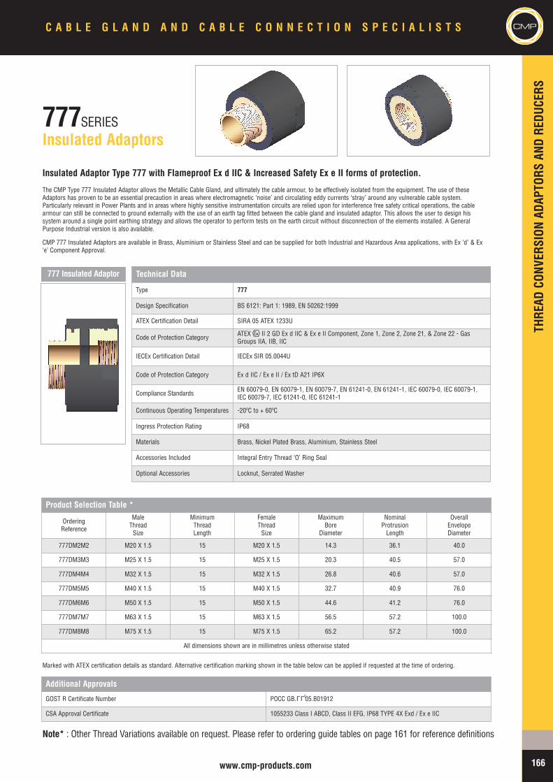
THRE
ADCO
NVER
SION
ADAP
TORS
ANDRE
DUCE
RS
CMPC A B L E G L A N D A N D C A B L E C O N N E C T I O N S P E C I A L I S T S
166www.cmp-products.com
777SERIESInsulated Adaptors
Insulated Adaptor Type 777 with Flameproof Ex d IIC & Increased Safety Ex e II forms of protection.
The CMP Type 777 Insulated Adaptor allows the Metallic Cable Gland, and ultimately the cable armour, to be effectively isolated from the equipment. The use of theseAdaptors has proven to be an essential precaution in areas where electromagnetic ‘noise’ and circulating eddy currents ‘stray’ around any vulnerable cable system.Particularly relevant in Power Plants and in areas where highly sensitive instrumentation circuits are relied upon for interference free safety critical operations, the cablearmour can still be connected to ground externally with the use of an earth tag fitted between the cable gland and insulated adaptor. This allows the user to design hissystem around a single point earthing strategy and allows the operator to perform tests on the earth circuit without disconnection of the elements installed. A GeneralPurpose Industrial version is also available.
CMP 777 Insulated Adaptors are available in Brass, Aluminium or Stainless Steel and can be supplied for both Industrial and Hazardous Area applications, with Ex ‘d’ & Ex‘e’ Component Approval.
Product Selection Table *
OrderingReference
MaleThreadSize
MinimumThreadLength
FemaleThreadSize
MaximumBore
Diameter
NominalProtrusionLength
OverallEnvelopeDiameter
777DM2M2 M20 X 1.5 15 M20 X 1.5 14.3 36.1 40.0
777DM3M3 M25 X 1.5 15 M25 X 1.5 20.3 40.5 57.0
777DM4M4 M32 X 1.5 15 M32 X 1.5 26.8 40.6 57.0
777DM5M5 M40 X 1.5 15 M40 X 1.5 32.7 40.9 76.0
777DM6M6 M50 X 1.5 15 M50 X 1.5 44.6 41.2 76.0
777DM7M7 M63 X 1.5 15 M63 X 1.5 56.5 57.2 100.0
777DM8M8 M75 X 1.5 15 M75 X 1.5 65.2 57.2 100.0
All dimensions shown are in millimetres unless otherwise stated
Additional Approvals
GOST R Certificate Number POCC GB. 05.B01912
CSA Approval Certificate 1055233 Class I ABCD, Class II EFG, IP68 TYPE 4X Exd / Ex e IIC
Marked with ATEX certification details as standard. Alternative certification marking shown in the table below can be applied if requested at the time of ordering.
Note* : Other Thread Variations available on request. Please refer to ordering guide tables on page 161 for reference definitions
777 Insulated Adaptor
LLU
Technical Data
Type 777
Design Specification BS 6121: Part 1: 1989, EN 50262:1999
ATEX Certification Detail SIRA 05 ATEX 1233U
Code of Protection Category ATEX II 2 GD Ex d IIC & Ex e II Component, Zone 1, Zone 2, Zone 21, & Zone 22 - GasGroups IIA, IIB, IIC
IECEx Certification Detail IECEx SIR 05.0044U
Code of Protection Category Ex d IIC / Ex e II / Ex tD A21 IP6X
Compliance Standards EN 60079-0, EN 60079-1, EN 60079-7, EN 61241-0, EN 61241-1, IEC 60079-0, IEC 60079-1,IEC 60079-7, IEC 61241-0, IEC 61241-1
Continuous Operating Temperatures -20ºC to + 60ºC
Ingress Protection Rating IP68
Materials Brass, Nickel Plated Brass, Aluminium, Stainless Steel
Accessories Included Integral Entry Thread ‘O’ Ring Seal
Optional Accessories Locknut, Serrated Washer

CMPTH
READ
CONV
ERSION
ADAP
TORS
ANDRE
DUCE
RSC A B L E G L A N D A N D C A B L E C O N N E C T I O N S P E C I A L I S T S
167 www.cmp-products.com
747SERIESStopper Plugs
Stopper Plug Type 747 with Flameproof Ex d IIC form of protection, with and without Tamper-proof facility.
The CMP Type 747 range of Flameproof Ex d Stopper Plugs is designed to provide a permanent or temporary means of blanking unused cable entry holes in Flameproofenclosures enabling the equipment to be safely deployed in the hazardous area. A General Purpose Industrial version is also available.
Always inserted from the outside of the enclosure, these Stopper Plugs are available with both external (Type A) and internal (Type B) Allen Key facility. The 747 Type BStopper Plug is considered as tamper-proof since it can only be removed from the inside, after the equipment has been de-energised and the terminal chamber coverremoved.
CMP Type 747 Stopper Plugs are available in Brass, Aluminium, Stainless Steel or Nylon (Exe) and can be supplied for both Industrial and Hazardous Area applications,with a variety of thread forms and sizes, including NPT. Please refer to Table ‘D’ on page 161 for further information on these options.
Technical Data
Type 747 (Type A & Type B)
Design Specification BS 6121: Part 1: 1989, EN 50262:1999
ATEX Certification Detail SIRA 01 ATEX 1284U, SIRA 02 ATEX 1003X
Code of Protection CategoryATEX II 2 GD Ex d IIC & Ex e II Component & Equipment, Zone 1, Zone 2, Zone 21, & Zone 22 - Gas Groups IIA, IIB, IIC
ATEX IM 2 Ex d I & Ex e I
IECEx Certification Detail IECEx SIR07.0056U
Code of Protection Category Ex d I / Ex e I / Ex d IIC / Ex e II / Ex tD A21 IP6X
Compliance Standards EN 60079-0, EN 60079-1, EN 60079-7, EN 61241-1, IEC 60079-0, IEC 60079-1, IEC 60079-7, IEC 61241-1
Continous Operating Temperatures -60ºC to + 200ºC (-20ºC to +60ºC Nylon version)
Ingress Protection Rating IP66
Materials Brass, Nickel Plated Brass, Aluminium, Stainless Steel, Nylon
Additional Approvals
Gost Ex Approval Certificate POCC GB. 05.B01367, POCC GB. 05.B01369
CSA Approval Certificate 1055233 Class I ABCD, Class II EFG, IP68 TYPE 4X Ex d IIC
UL Listing file reference EBNV.E214221 Class I ABCD, Class II EFG, & Class III
Marked with ATEX certification details as standard. Alternative certification marking shown in the table below can be applied if requested at the time of ordering.
Note*: Other Thread Variations available on request. Please refer to ordering guide tables on page 161 for reference definitions
Standard Product Selection Table *
OrderingReference
ThreadSize
MinimumThreadLength
Allen KeySize A/F
747-F-A-M-1 M16 X 1.5 15 M8
747-F-A-M-2 M20 X 1.5 15 M10
747-F-A-M-3 M25 X 1.5 15 M10
747-F-A-M-4 M32 X 1.5 15 M10
747-F-A-M-5 M40 X 1.5 15 M10
747-F-A-M-6 M50 X 1.5 15 M10
747-F-A-M-7 M63 X 1.5 15 M14
747-F-A-M-8 M75 X 1.5 15 M14
747-F-A-M-9 M90 X 2 15 M14
747-F-A-M-10 M100 X 2 15 M14
All dimensions shown are in millimetres unless otherwise stated
HOW TO ORDER *e.g. 747 – F – A – M – M – 3 - 1= Ex d - Type A - M25 - Aluminium
Ex ‘d’ RecessedStopper Plug Type ‘A’
Ex ‘d’ RecessedStopper Plug Type ‘B’
Note: For Tamper Proof Type B Stopper Plugs please substitute the letter Awith the letter B in the Ordering Reference list opposite.
TYPE ‘A’ TYPE ‘B’
TYPE ‘A’ TYPE ‘B’
LLU LLU
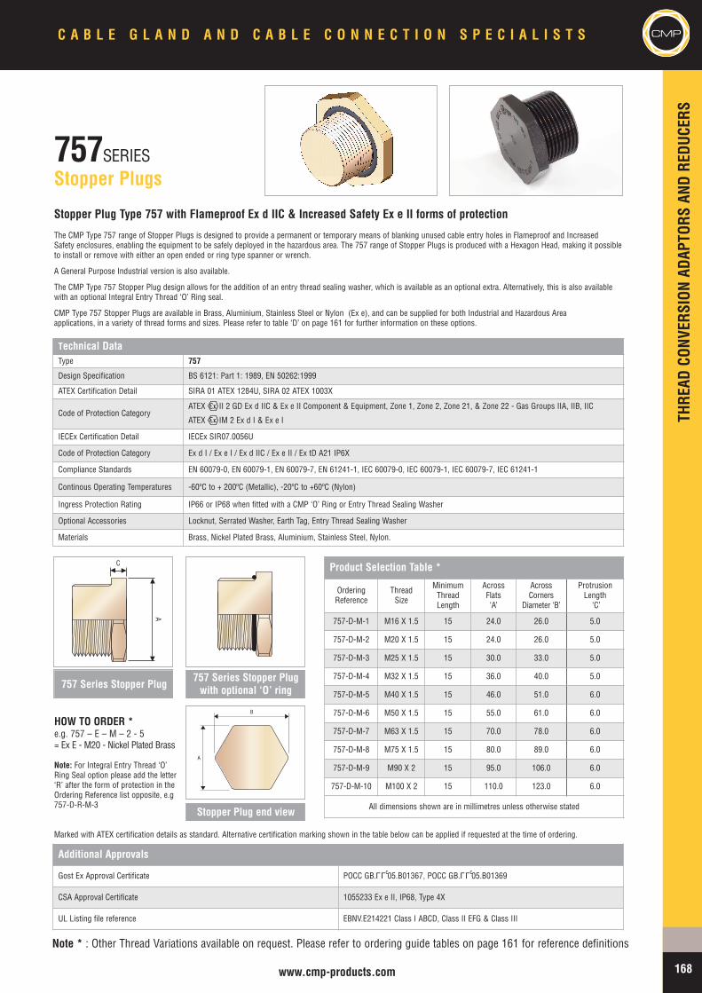
THRE
ADCO
NVER
SION
ADAP
TORS
ANDRE
DUCE
RS
CMPC A B L E G L A N D A N D C A B L E C O N N E C T I O N S P E C I A L I S T S
168www.cmp-products.com
757SERIESStopper Plugs
Stopper Plug Type 757 with Flameproof Ex d IIC & Increased Safety Ex e II forms of protection
The CMP Type 757 range of Stopper Plugs is designed to provide a permanent or temporary means of blanking unused cable entry holes in Flameproof and IncreasedSafety enclosures, enabling the equipment to be safely deployed in the hazardous area. The 757 range of Stopper Plugs is produced with a Hexagon Head, making it possibleto install or remove with either an open ended or ring type spanner or wrench.
A General Purpose Industrial version is also available.
The CMP Type 757 Stopper Plug design allows for the addition of an entry thread sealing washer, which is available as an optional extra. Alternatively, this is also availablewith an optional Integral Entry Thread ‘O’ Ring seal.
CMP Type 757 Stopper Plugs are available in Brass, Aluminium, Stainless Steel or Nylon (Ex e), and can be supplied for both Industrial and Hazardous Areaapplications, in a variety of thread forms and sizes. Please refer to table ‘D’ on page 161 for further information on these options.
Technical DataType 757
Design Specification BS 6121: Part 1: 1989, EN 50262:1999
ATEX Certification Detail SIRA 01 ATEX 1284U, SIRA 02 ATEX 1003X
Code of Protection CategoryATEX II 2 GD Ex d IIC & Ex e II Component & Equipment, Zone 1, Zone 2, Zone 21, & Zone 22 - Gas Groups IIA, IIB, IIC
ATEX IM 2 Ex d I & Ex e I
IECEx Certification Detail IECEx SIR07.0056U
Code of Protection Category Ex d I / Ex e I / Ex d IIC / Ex e II / Ex tD A21 IP6X
Compliance Standards EN 60079-0, EN 60079-1, EN 60079-7, EN 61241-1, IEC 60079-0, IEC 60079-1, IEC 60079-7, IEC 61241-1
Continous Operating Temperatures -60ºC to + 200ºC (Metallic), -20ºC to +60ºC (Nylon)
Ingress Protection Rating IP66 or IP68 when fitted with a CMP ‘O’ Ring or Entry Thread Sealing Washer
Optional Accessories Locknut, Serrated Washer, Earth Tag, Entry Thread Sealing Washer
Materials Brass, Nickel Plated Brass, Aluminium, Stainless Steel, Nylon.
Additional Approvals
Gost Ex Approval Certificate POCC GB. 05.B01367, POCC GB. 05.B01369
CSA Approval Certificate 1055233 Ex e II, IP68, Type 4X
UL Listing file reference EBNV.E214221 Class I ABCD, Class II EFG & Class III
Marked with ATEX certification details as standard. Alternative certification marking shown in the table below can be applied if requested at the time of ordering.
Note: For Integral Entry Thread ‘O’Ring Seal option please add the letter‘R’ after the form of protection in theOrdering Reference list opposite, e.g757-D-R-M-3
Product Selection Table *
OrderingReference
ThreadSize
MinimumThreadLength
AcrossFlats‘A’
AcrossCorners
Diameter ‘B’
ProtrusionLength‘C’
757-D-M-1 M16 X 1.5 15 24.0 26.0 5.0
757-D-M-2 M20 X 1.5 15 24.0 26.0 5.0
757-D-M-3 M25 X 1.5 15 30.0 33.0 5.0
757-D-M-4 M32 X 1.5 15 36.0 40.0 5.0
757-D-M-5 M40 X 1.5 15 46.0 51.0 6.0
757-D-M-6 M50 X 1.5 15 55.0 61.0 6.0
757-D-M-7 M63 X 1.5 15 70.0 78.0 6.0
757-D-M-8 M75 X 1.5 15 80.0 89.0 6.0
757-D-M-9 M90 X 2 15 95.0 106.0 6.0
757-D-M-10 M100 X 2 15 110.0 123.0 6.0
All dimensions shown are in millimetres unless otherwise stated
HOW TO ORDER *e.g. 757 – E – M – 2 - 5= Ex E - M20 - Nickel Plated Brass
757 Series Stopper Plug757 Series Stopper Plugwith optional ‘O’ ring
Stopper Plug end view
B
A
Note * : Other Thread Variations available on request. Please refer to ordering guide tables on page 161 for reference definitions
A
C
LLU LLU
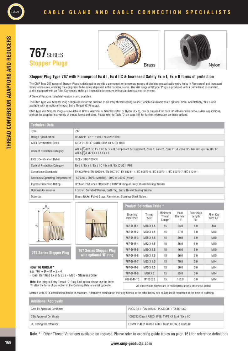
CMPTH
READ
CONV
ERSION
ADAP
TORS
ANDRE
DUCE
RSC A B L E G L A N D A N D C A B L E C O N N E C T I O N S P E C I A L I S T S
169 www.cmp-products.com
767SERIESStopper Plugs
Stopper Plug Type 767 with Flameproof Ex d I, Ex d IIC & Increased Safety Ex e I, Ex e II forms of protection
The CMP Type 767 range of Stopper Plugs is designed to provide a permanent or temporary means of blanking unused cable entry holes in Flameproof and IncreasedSafety enclosures, enabling the equipment to be safely deployed in the hazardous area. The 767 range of Stopper Plugs is produced with a Dome Head as standard,and is equipped with an Allen Key recess making it impossible to remove with a standard spanner or wrench.
A General Purpose Industrial version is also available.
The CMP Type 767 Stopper Plug design allows for the addition of an entry thread sealing washer, which is available as an optional extra. Alternatively, this is alsoavailable with an optional Integral Entry Thread ‘O’ Ring seal.
CMP Type 767 Stopper Plugs are available in Brass, Aluminium, Stainless Steel or Nylon (Ex e), can be supplied for both Industrial and Hazardous Area applications,and can be supplied in a variety of thread forms and sizes. Please refer to Table ‘D’ on page 161 for further information on these options.
Technical DataType 767
Design Specification BS 6121: Part 1: 1989, EN 50262:1999
ATEX Certification Detail SIRA 01 ATEX 1284U, SIRA 01 ATEX 1003
Code of Protection CategoryATEX II 2 GD Ex d IIC & Ex e II Component & Equipment, Zone 1, Zone 2, Zone 21, & Zone 22 - Gas Groups IIA, IIB, IICATEX I M2 Ex d I & Ex e I
IECEx Certification Detail IECEx SIR07.0056U
Code of Protection Category Ex d I / Ex e I / Ex d IIC / Ex e II / Ex tD A21 IP66
Compliance Standards EN 60079-0, EN 60079-1, EN 60079-7, EN 61241-1, IEC 60079-0, IEC 60079-1, IEC 60079-7, IEC 61241-1
Continous Operating Temperatures -60ºC to + 200ºC (Metallic), -20ºC to +60ºC (Nylon)
Ingress Protection Rating IP66 or IP68 when fitted with a CMP ‘O’ Ring or Entry Thread Sealing Washer
Optional Accessories Locknut, Serrated Washer, Earth Tag, Entry Thread Sealing Washer
Materials Brass, Nickel Plated Brass, Aluminium, Stainless Steel, Nylon.
Additional Approvals
Gost Ex Approval Certificate POCC GB. 05.B01367, POCC GB. 05.B01369
CSA Approval Certificate 1055233 Class I ABCD, IP68, TYPE 4X Ex d / Ex e IIC
UL Listing file reference EBNV.E214221 Class I ABCD, Class II EFG, & Class III
Marked with ATEX certification details as standard. Alternative certification marking shown in the table below can be applied if requested at the time of ordering.
767 Series Stopper Plug
Note: For Integral Entry Thread ‘O’ Ring Seal option please use the letter‘R’ after the form of protection in the Ordering Reference list opposite.
HOW TO ORDER *e.g. 767 – D – M – 2 - 4= Dual Certified Ex d & Ex e - M20 - Stainless Steel
767 Series Stopper Plugwith optional ‘O’ ring
Note * : Other Thread Variations available on request. Please refer to ordering guide tables on page 161 for reference definitions
Product Selection Table *
OrderingReference
ThreadSize
MinimumThreadLength
HeadDiameter
‘A’
ProtrusionLength‘B’
Allen KeySize A/F
767-D-M-1 M16 X 1.5 15 23.0 5.0 M8
767-D-M-2 M20 X 1.5 15 27.0 5.0 M10
767-D-M-3 M25 X 1.5 15 30.0 5.0 M10
767-D-M-4 M32 X 1.5 15 36.0 5.0 M10
767-D-M-5 M40 X 1.5 15 46.0 5.0 M10
767-D-M-6 M50 X 1.5 15 56.0 5.0 M10
767-D-M-7 M63 X 1.5 15 70.0 5.0 M14
767-D-M-8 M75 X 1.5 15 80.0 5.0 M14
767-D-M-9 M90 X 2 15 95.0 5.0 M14
767-D-M-10 M100 X 2 15 110.0 5.0 M14
All dimensions shown are in millimetres unless otherwise stated
A
B
Brass Nylon
LLU LLU
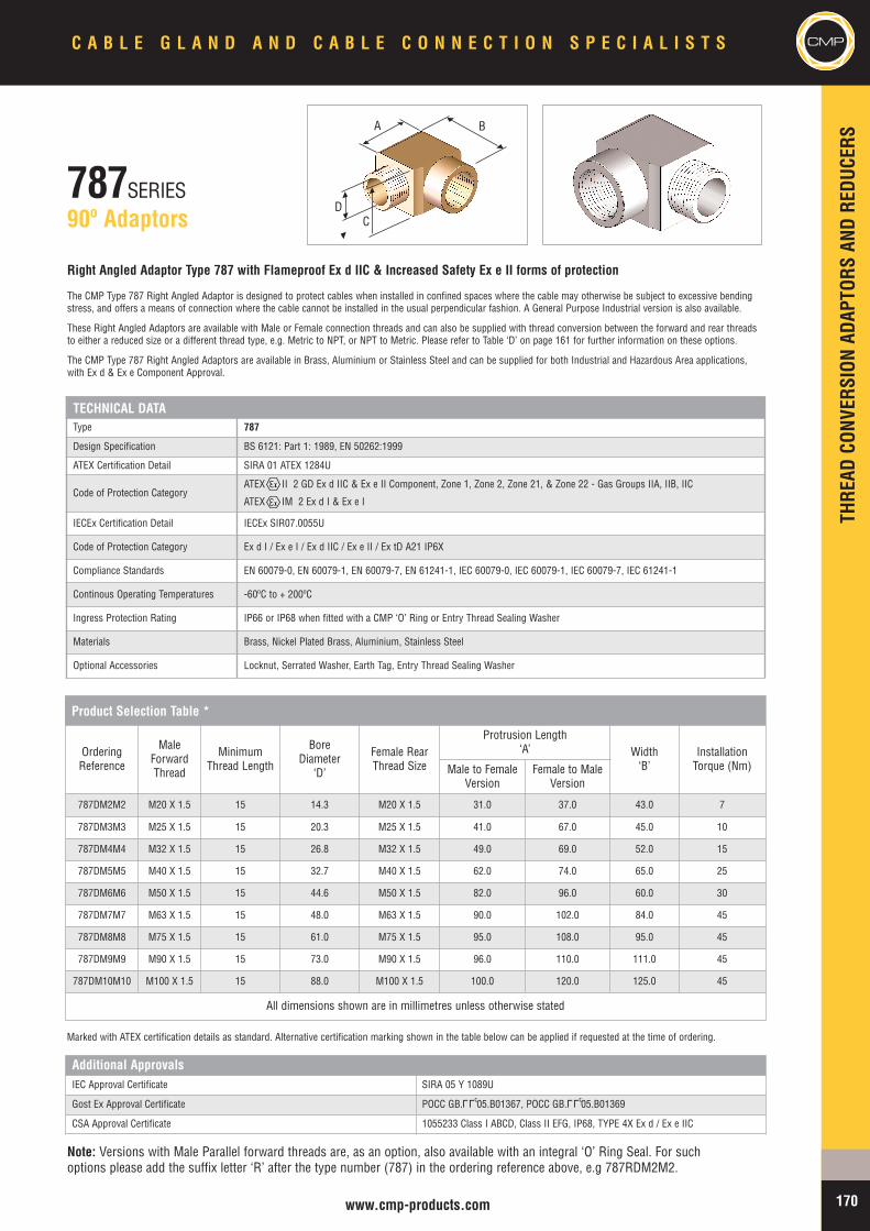
THRE
ADCO
NVER
SION
ADAP
TORS
ANDRE
DUCE
RS
CMPC A B L E G L A N D A N D C A B L E C O N N E C T I O N S P E C I A L I S T S
170www.cmp-products.com
787SERIES90º Adaptors
Right Angled Adaptor Type 787 with Flameproof Ex d IIC & Increased Safety Ex e II forms of protection
The CMP Type 787 Right Angled Adaptor is designed to protect cables when installed in confined spaces where the cable may otherwise be subject to excessive bendingstress, and offers a means of connection where the cable cannot be installed in the usual perpendicular fashion. A General Purpose Industrial version is also available.
These Right Angled Adaptors are available with Male or Female connection threads and can also be supplied with thread conversion between the forward and rear threadsto either a reduced size or a different thread type, e.g. Metric to NPT, or NPT to Metric. Please refer to Table ‘D’ on page 161 for further information on these options.
The CMP Type 787 Right Angled Adaptors are available in Brass, Aluminium or Stainless Steel and can be supplied for both Industrial and Hazardous Area applications,with Ex d & Ex e Component Approval.
TECHNICAL DATAType 787
Design Specification BS 6121: Part 1: 1989, EN 50262:1999
ATEX Certification Detail SIRA 01 ATEX 1284U
Code of Protection CategoryATEX II 2 GD Ex d IIC & Ex e II Component, Zone 1, Zone 2, Zone 21, & Zone 22 - Gas Groups IIA, IIB, IIC
ATEX IM 2 Ex d I & Ex e I
IECEx Certification Detail IECEx SIR07.0055U
Code of Protection Category Ex d I / Ex e I / Ex d IIC / Ex e II / Ex tD A21 IP6X
Compliance Standards EN 60079-0, EN 60079-1, EN 60079-7, EN 61241-1, IEC 60079-0, IEC 60079-1, IEC 60079-7, IEC 61241-1
Continous Operating Temperatures -60ºC to + 200ºC
Ingress Protection Rating IP66 or IP68 when fitted with a CMP ‘O’ Ring or Entry Thread Sealing Washer
Materials Brass, Nickel Plated Brass, Aluminium, Stainless Steel
Optional Accessories Locknut, Serrated Washer, Earth Tag, Entry Thread Sealing Washer
Product Selection Table *
OrderingReference
MaleForwardThread
MinimumThread Length
BoreDiameter
‘D’
Female RearThread Size
Protrusion Length‘A’ Width
‘B’InstallationTorque (Nm)Male to Female
VersionFemale to Male
Version
787DM2M2 M20 X 1.5 15 14.3 M20 X 1.5 31.0 37.0 43.0 7
787DM3M3 M25 X 1.5 15 20.3 M25 X 1.5 41.0 67.0 45.0 10
787DM4M4 M32 X 1.5 15 26.8 M32 X 1.5 49.0 69.0 52.0 15
787DM5M5 M40 X 1.5 15 32.7 M40 X 1.5 62.0 74.0 65.0 25
787DM6M6 M50 X 1.5 15 44.6 M50 X 1.5 82.0 96.0 60.0 30
787DM7M7 M63 X 1.5 15 48.0 M63 X 1.5 90.0 102.0 84.0 45
787DM8M8 M75 X 1.5 15 61.0 M75 X 1.5 95.0 108.0 95.0 45
787DM9M9 M90 X 1.5 15 73.0 M90 X 1.5 96.0 110.0 111.0 45
787DM10M10 M100 X 1.5 15 88.0 M100 X 1.5 100.0 120.0 125.0 45
All dimensions shown are in millimetres unless otherwise stated
Marked with ATEX certification details as standard. Alternative certification marking shown in the table below can be applied if requested at the time of ordering.
Additional ApprovalsIEC Approval Certificate SIRA 05 Y 1089U
Gost Ex Approval Certificate POCC GB. 05.B01367, POCC GB. 05.B01369
CSA Approval Certificate 1055233 Class I ABCD, Class II EFG, IP68, TYPE 4X Ex d / Ex e IIC
Note: Versions with Male Parallel forward threads are, as an option, also available with an integral ‘O’ Ring Seal. For suchoptions please add the suffix letter ‘R’ after the type number (787) in the ordering reference above, e.g 787RDM2M2.
CD
A B
LLU LLU
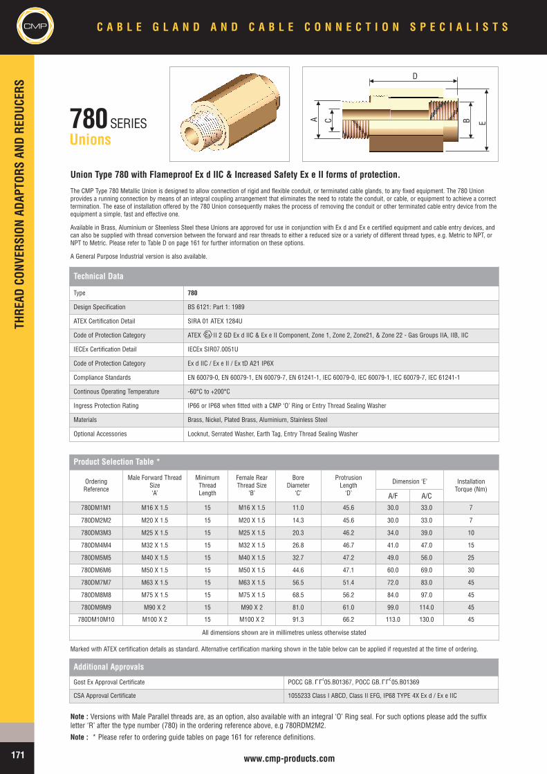
CMPTH
READ
CONV
ERSION
ADAP
TORS
ANDRE
DUCE
RSC A B L E G L A N D A N D C A B L E C O N N E C T I O N S P E C I A L I S T S
171 www.cmp-products.com
780SERIESUnions
Union Type 780 with Flameproof Ex d IIC & Increased Safety Ex e II forms of protection.
The CMP Type 780 Metallic Union is designed to allow connection of rigid and flexible conduit, or terminated cable glands, to any fixed equipment. The 780 Unionprovides a running connection by means of an integral coupling arrangement that eliminates the need to rotate the conduit, or cable, or equipment to achieve a correcttermination. The ease of installation offered by the 780 Union consequently makes the process of removing the conduit or other terminated cable entry device from theequipment a simple, fast and effective one.
Available in Brass, Aluminium or Steenless Steel these Unions are approved for use in conjunction with Ex d and Ex e certified equipment and cable entry devices, andcan also be supplied with thread conversion between the forward and rear threads to either a reduced size or a variety of different thread types, e.g. Metric to NPT, orNPT to Metric. Please refer to Table D on page 161 for further information on these options.
A General Purpose Industrial version is also available.
Technical Data
Type 780
Design Specification BS 6121: Part 1: 1989
ATEX Certification Detail SIRA 01 ATEX 1284U
Code of Protection Category ATEX II 2 GD Ex d IIC & Ex e II Component, Zone 1, Zone 2, Zone21, & Zone 22 - Gas Groups IIA, IIB, IIC
IECEx Certification Detail IECEx SIR07.0051U
Code of Protection Category Ex d IIC / Ex e II / Ex tD A21 IP6X
Compliance Standards EN 60079-0, EN 60079-1, EN 60079-7, EN 61241-1, IEC 60079-0, IEC 60079-1, IEC 60079-7, IEC 61241-1
Continous Operating Temperature -60°C to +200°C
Ingress Protection Rating IP66 or IP68 when fitted with a CMP ‘O’ Ring or Entry Thread Sealing Washer
Materials Brass, Nickel, Plated Brass, Aluminium, Stainless Steel
Optional Accessories Locknut, Serrated Washer, Earth Tag, Entry Thread Sealing Washer
Product Selection Table *
OrderingReference
Male Forward ThreadSize‘A’
MinimumThreadLength
Female RearThread Size
‘B’
BoreDiameter
‘C’
ProtrusionLength‘D’
Dimension ‘E’ InstallationTorque (Nm)
780DM1M1 M16 X 1.5 15 M16 X 1.5 11.0 45.6 30.0 33.0 7
780DM2M2 M20 X 1.5 15 M20 X 1.5 14.3 45.6 30.0 33.0 7
780DM3M3 M25 X 1.5 15 M25 X 1.5 20.3 46.2 34.0 39.0 10
780DM4M4 M32 X 1.5 15 M32 X 1.5 26.8 46.7 41.0 47.0 15
780DM5M5 M40 X 1.5 15 M40 X 1.5 32.7 47.2 49.0 56.0 25
780DM6M6 M50 X 1.5 15 M50 X 1.5 44.6 47.1 60.0 69.0 30
780DM7M7 M63 X 1.5 15 M63 X 1.5 56.5 51.4 72.0 83.0 45
780DM8M8 M75 X 1.5 15 M75 X 1.5 68.5 56.2 84.0 97.0 45
780DM9M9 M90 X 2 15 M90 X 2 81.0 61.0 99.0 114.0 45
780DM10M10 M100 X 2 15 M100 X 2 91.3 66.2 113.0 130.0 45
All dimensions shown are in millimetres unless otherwise stated
Additional Approvals
Gost Ex Approval Certificate POCC GB. 05.B01367, POCC GB. 05.B01369
CSA Approval Certificate 1055233 Class I ABCD, Class II EFG, IP68 TYPE 4X Ex d / Ex e IIC
Marked with ATEX certification details as standard. Alternative certification marking shown in the table below can be applied if requested at the time of ordering.
Note : Versions with Male Parallel threads are, as an option, also available with an integral ‘O’ Ring seal. For such options please add the suffixletter ‘R’ after the type number (780) in the ordering reference above, e.g 780RDM2M2.
Note : * Please refer to ordering guide tables on page 161 for reference definitions.
A B
D
EC
A/F A/C
LLU LLU
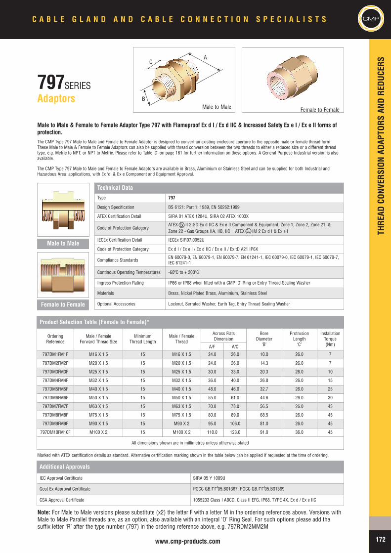
THRE
ADCO
NVER
SION
ADAP
TORS
ANDRE
DUCE
RS
CMPC A B L E G L A N D A N D C A B L E C O N N E C T I O N S P E C I A L I S T S
172www.cmp-products.com
797SERIESAdaptors
Male to Male & Female to Female Adaptor Type 797 with Flameproof Ex d I / Ex d IIC & Increased Safety Ex e I / Ex e II forms ofprotection.The CMP Type 797 Male to Male and Female to Female Adaptor is designed to convert an existing enclosure aperture to the opposite male or female thread form.These Male to Male & Female to Female Adaptors can also be supplied with thread conversion between the two threads to either a reduced size or a different threadtype, e.g. Metric to NPT, or NPT to Metric. Please refer to Table ‘D’ on page 161 for further information on these options. A General Purpose Industrial version is alsoavailable.
The CMP Type 797 Male to Male and Female to Female Adaptors are available in Brass, Aluminium or Stainless Steel and can be supplied for both Industrial andHazardous Area applications, with Ex ‘d’ & Ex e Component and Equipment Approval.
Technical Data
Type 797
Design Specification BS 6121: Part 1: 1989, EN 50262:1999
ATEX Certification Detail SIRA 01 ATEX 1284U, SIRA 02 ATEX 1003X
Code of Protection CategoryATEX II 2 GD Ex d IIC & Ex e II Component & Equipment, Zone 1, Zone 2, Zone 21, &Zone 22 - Gas Groups IIA, IIB, IIC ATEX IM 2 Ex d I & Ex e I
IECEx Certification Detail IECEx SIR07.0052U
Code of Protection Category Ex d I / Ex e I / Ex d IIC / Ex e II / Ex tD A21 IP6X
Compliance Standards EN 60079-0, EN 60079-1, EN 60079-7, EN 61241-1, IEC 60079-0, IEC 60079-1, IEC 60079-7,IEC 61241-1
Continous Operating Temperatures -60ºC to + 200ºC
Ingress Protection Rating IP66 or IP68 when fitted with a CMP ‘O’ Ring or Entry Thread Sealing Washer
Materials Brass, Nickel Plated Brass, Aluminium, Stainless Steel
Optional Accessories Locknut, Serrated Washer, Earth Tag, Entry Thread Sealing Washer
Marked with ATEX certification details as standard. Alternative certification marking shown in the table below can be applied if requested at the time of ordering.
Additional Approvals
IEC Approval Certificate SIRA 05 Y 1089U
Gost Ex Approval Certificate POCC GB. 05.B01367, POCC GB. 05.B01369
CSA Approval Certificate 1055233 Class I ABCD, Class II EFG, IP68, TYPE 4X, Ex d / Ex e IIC
Note: For Male to Male versions please substitute (x2) the letter F with a letter M in the ordering references above. Versions withMale to Male Parallel threads are, as an option, also available with an integral ‘O’ Ring Seal. For such options please add thesuffix letter ‘R’ after the type number (797) in the ordering reference above, e.g. 797RDM2MM2M
Product Selection Table (Female to Female)*
OrderingReference
Male / FemaleForward Thread Size
MinimumThread Length
Male / FemaleThread
Across FlatsDimension
BoreDiameter
‘B’
ProtrusionLength‘C’
InstallationTorque(Nm)
797DM1FM1F M16 X 1.5 15 M16 X 1.5 24.0 26.0 10.0 26.0 7
797DM2FM2F M20 X 1.5 15 M20 X 1.5 24.0 26.0 14.3 26.0 7
797DM3FM3F M25 X 1.5 15 M25 X 1.5 30.0 33.0 20.3 26.0 10
797DM4FM4F M32 X 1.5 15 M32 X 1.5 36.0 40.0 26.8 26.0 15
797DM5FM5F M40 X 1.5 15 M40 X 1.5 48.0 46.0 32.7 26.0 25
797DM6FM6F M50 X 1.5 15 M50 X 1.5 55.0 61.0 44.6 26.0 30
797DM7FM7F M63 X 1.5 15 M63 X 1.5 70.0 78.0 56.5 26.0 45
797DM8FM8F M75 X 1.5 15 M75 X 1.5 80.0 89.0 68.5 26.0 45
797DM9FM9F M90 X 1.5 15 M90 X 2 95.0 106.0 81.0 26.0 45
797DM10FM10F M100 X 2 15 M100 X 2 110.0 123.0 91.0 36.0 45
All dimensions shown are in millimetres unless otherwise stated
Male to Male
Female to Female
Male to Male Female to Female
B
CA
A/F A/C
LLU LLU
CMPAC
CESS
ORIES
C A B L E G L A N D A N D C A B L E C O N N E C T I O N S P E C I A L I S T S
173 www.cmp-products.com
Brass Locknuts are the recommended items used in securing brass cable glands,unions, adaptors, reducers, and stopper plugs to a gland plate or into equipment.
Zinc Plated Mild Steel locknuts are a cost effective alternative to brass locknuts andshould be used only in dry, low humidity conditions.
Aluminium locknuts are recommended when installing CMP Aluminium Cable Glandsto prevent the electrolytic action of galvanic corrosion which can occur when dis-similar metals are coupled together.
Note: Alternative materials are also available. Please refer to Table ‘E’ on page 161 for orderingreference numbers, e.g 20LN4 for M20 Stainless Steel Locknut, 050NPTLN4 for 1/2” NPTStainless Steel Locknut.
LOCKNUTS
METRIC - LOCKNUTS
OrderingReference(Brass)
ThreadDiameter
‘A’
MinimumThickness
Across FlatsDimension
‘B’
Across CornersDiameter
‘C’
16LN M16 X 1.5 3.2 22.0 25.4
20LN M20 X 1.5 3.2 24.0 28.6
25LN M25 X 1.5 3.2 30.0 35.0
32LN M32 X 1.5 3.2 36.0 42.0
40LN M40 X 1.5 4.8 46.0 53.0
50LN M50 X 1.5 6.3 55.0 64.0
63LN M63 X 1.5 6.3 70.0 81.0
75LN M75 X 1.5 6.3 80.0 98.0
90LN M90 X 2 9.5 108.0 125.0
100LN M100 X 2 9.5 122.0 141.5
All dimensions shown are in millimetres unless otherwise stated
NPT - LOCKNUTS
OrderingReference(Brass)
ThreadDiameter
‘A’
MinimumThickness
Across FlatsDimension
‘B’
Across CornersDiameter
‘C’
050NPTLN 1/2” NPT 4.75 27.0 29.3
075NPTLN 3/4”NPT 4.75 33.0 35.8
100NPTLN 1” NPT 4.5 41.0 45.0
125NPTLN 1 1/4” NPT 4.75 50.0 53.4
150NPTLN 1 1/2”NPT 5.1 60.0 69.0
200NPTLN 2” NPT 5.1 70.0 80.2
250NPTLN 2 1/2” NPT 10.0 79.0 90.5
300NPTLN 3” NPT 10.0 108.0 123.0
350NPTLN 3 1/2” NPT 11.5 114.0 131.0
All dimensions shown are in millimetres unless otherwise stated
Available in Stainless Steel as standard, these “shake-proof” Serrated Washers fittedinternally to the equipment and before a locknut act as an anti-vibration device toprevent the cable gland or other cable entry device and locknut arrangement frominadvertently loosening in service.
Note: Alternative materials are also available. Please refer to Table ‘E’ on page 161for ordering reference numbers, e.g 20SW4 for M20 Stainless Steel SerratedWasher, 050NPTSW4 for 1/2” NPT Stainless Steel Serrated Washer.
SERRATED WASHERS
METRIC - SERRATED WASHERSOrderingReference
(Plated Steel)
ReferenceDiameter
‘A’
MinimumThickness
ExternalDiameter
‘B’
16SW M16 3.3 25.4
20SW M20 3.7 32.0
25SW M25 3.7 40.0
32SW M32 3.7 44.0
40SW M40 3.7 59.0
50SW M50 3.7 80.0
63SW M63 4.5 100.0
75SW M75 5.0 112.0
90SW M90 5.0 120.0
100SW M100 6.3 150.0
All dimensions shown are in millimetres unless otherwise stated
NPT - SERRATED WASHERS
OrderingReference
(Plated Steel)
ReferenceDiameter
‘A’
MinimumThickness
ExternalDiameter
‘B’
050NPTSW 1/2” NPT 3.7 32.0
075NPTSW 3/4”NPT 3.7 40.0
100NPTSW 1” NPT 3.7 44.0
125NPTSW 1 1/4” NPT 3.7 59.0
150NPTSW 1 1/2”NPT 3.7 80.0
200NPTSW 2” NPT 4.5 100.0
250NPTSW 2 1/2” NPT 5.0 112.0
300NPTSW 3” NPT 5.0 120.0
350NPTSW 3 1/2” NPT 6.3 150.0
All dimensions shown are in millimetres unless otherwise stated
A
A
BB
C
ACCESSORIES
ACCE
SSOR
IES
CMPC A B L E G L A N D A N D C A B L E C O N N E C T I O N S P E C I A L I S T S
174www.cmp-products.com
CMP manufacture a range of push on shrouds which are used to minimise the risk of dirt orforeign substances gathering on the Cable Gland body, and/or point of cable to gland interface.Standard shrouds are produced in Black PVC and PCP. CMP LSF (Blue/Grey) shrouds are availablefrom stock. Table below shows typical examples of CMP shrouds.
PVC, PCP & LSF shrouds are also manufactured in alternative colours including Red, Blue andWhite, to suit a wide variety of customer requirements, other colours are available.
SHROUDS
COLOUR CODED SHROUDS
CMP slip on earth tags, Installed between the cable gland and equipment, provide anearth bond connection as specified in BS6121:Part 5:1993 and also complies withcategory ‘B’ rating specified in BS EN 50262:1999. The following table of fault currentratings relates to CMP Brass Earth Tags.
CMP Earth TagSize
Short Circuit RatingsSymmetrical Fault Current
(kA) for 1 second20 3.0625 4.0032 5.4040 7.2050 10.4063 10.4075 10.40
EARTH TAGS
METRIC - EARTH TAGSOrderingReference(Brass)
ReferenceDiameter
‘A’
MinimumThickness
NominalDiameter
‘C’
HoleSize‘D’
NominalLength‘E’
NominalCentres‘F’
16ET M16 1.5 25.4 M6 49.3 30.2
20ET M20 1.5 27.1 M6 53.4 33.1
25ET M25 1.5 35.1 M6 59.4 35.6
32ET M32 1.5 45.2 M12 77.0 43.1
40ET M40 1.5 53.7 M13 88.7 45.4
50ET M50 1.5 65.2 M13 111.1 58.1
63ET M63 1.5 82.6 M13 128.6 66.8
75ET M75 1.5 95.4 M13 141.1 73.0
90ET M90 1.5 114.2 M13 161.0 85.0
100ET M100 1.5 126.0 M13 194.0 118.0
All dimensions shown are in millimetres unless otherwise stated
NPT - EARTH TAGS
OrderingReference(Brass)
ReferenceDiameter
‘A’
MinimumThickness
NominalDiameter
‘C’
HoleSize‘D’
NominalLength‘E’
NominalCentres‘F’
050NPTET 1/2” NPT 1.5 27.1 M6 53.4 33.1
075NPTET 3/4”NPT 1.5 35.1 M6 59.4 35.6
100NPTET 1” NPT 1.5 45.2 M12 77.0 43.1
125NPTET 1 1/4” NPT 1.5 53.7 M13 88.7 45.4
150NPTET 1 1/2”NPT 1.5 65.2 M13 111.1 58.1
200NPTET 2” NPT 1.5 82.6 M13 128.6 66.8
250NPTET 2 1/2” NPT 1.5 95.4 M13 141.1 73.0
300NPTET 3” NPT 1.5 114.2 M13 161.0 85.0
350NPTET 3 1/2” NPT 1.5 126.0 M13 194.0 118.0
All dimensions shown are in millimetres unless otherwise stated
E
D
A
F
C
Note: Alternative materials are also available. Please refer to Table ‘E’ on page 161for ordering reference numbers, e.g 20ET4 for M20 Stainless Steel Earth Tag,050NPTET4 for 1/2” NPT Stainless Steel Earth Tag.
GLANDTYPE 20/16 20S 20 25 32 40 50S 50 63S 63 75S 75 90
BWL PVC02 PVC04 PVC06 PVC09 PVC11 PVC13 PVC17 PVC20 PVC22 PVC25 PVC28 PVC30 PVC32
A2 PVC02 PVC04 PVC05 PVC09 PVC10 PVC13 PVC14 PVC17 PVC20 PVC22 PVC24 PVC26 PVC31
E1W PVC02 PVC04 PVC06 PVC09 PVC11 PVC15 PVC18 PVC21 PVC23 PVC25 PVC28 PVC30 PVC32
SHROUD REFRENCES
ACCESSORIES
CMPAC
CESS
ORIES
C A B L E G L A N D A N D C A B L E C O N N E C T I O N S P E C I A L I S T S
175 www.cmp-products.com
To maintain the Ingress Protection rating between the equipment and cable gland itmay be necessary to fit an Entry Thread Sealing Washer at the gland entry interface.For Explosion Protected equipment it is essential to maintain the integrity of thedegree of Ingress Protection at which the equipment has been rated.
The need for a sealing washer will very much depend on the Ingress Protectionrating and code of protection of the equipment and the type of entry holes availablewithin that equipment.
For example when Ex e apparatus or terminal boxes which are permitted to haveuntapped through clearance holes it will be necessary to fit a sealing washer toensure that the minimum IP54 requirement (for gas / vapour hazards) is met.Whereas other equipment having tapped entry holes may not require a sealingwasher to maintain the rated integrity of the installation, or the minimumrequirement for the specified form of protection.
The CMP Entry Thread Sealing Washers are produced in 2mm Thick White Nylon asstandard which are recommended and meet the specified requirements of Shell’sOffshore operations.
To verify the effectiveness of the CMP nylon entry sealing washers independent 3rdparty tests to EN 60529 have been successfully conducted on Cable Gland at IP66,IP67 & IP68 levels of protection. CMP can therefore provide Independentdocumentary evidence of such tests to the highest standards.
Red Fibre Washers can also be supplied to order but careful consideration should begiven to their use in sub zero climates where absorption, freezing and cracking havebeen known to occur, ultimately impairing the degree of Ingress Protectionattainable.
CMP also offers as an alternative, cable glands, adaptors, reducers, and stopperplugs with Integral Entry Thread ‘O’ Ring Seal, as pictured opposite.
ENTRY THREAD SEALING WASHERS
WHITE METRIC ENTRY THREAD SEALING WASHERS
OrderingReference
ReferenceDiameter
‘A’
MinimumThickness
ExternalDiameter
‘B’
16ETS2 M16 2.0 25.4
20ETS2 M20 2.0 28.6
25ETS2 M25 2.0 35.0
32ETS2 M32 2.0 44.5
40ETS2 M40 2.0 50.8
50ETS2 M50 2.0 65.0
63ETS2 M63 2.0 76.2
75ETS2 M75 2.0 95.0
90ETS2 M90 2.0 110.0
All dimensions shown are in millimetres unless otherwise stated
GREEN NPT ENTRY THREAD SEALING WASHERS
OrderingReference
ReferenceDiameter
‘A’
MinimumThickness
ExternalDiameter
‘B’
050NPTETS 1/2” NPT 2.0 28.6
075NPTETS 3/4”NPT 2.0 35.0
100NPTETS 1” NPT 2.0 44.5
125NPTETS 1 1/4” NPT 2.0 50.8
150NPTETS 1 1/2”NPT 2.0 65.0
200NPTETS 2” NPT 2.0 76.2
250NPTETS 2 1/2” NPT 2.0 95.0
300NPTETS 3” NPT 2.0 110.0
All dimensions shown are in millimetres unless otherwise stated
To the best of our knowledge the information contained in this document is accurate at the time of going to print and CMP reserve the right toimprove or modify any products illustrated without prior notification. CMP can not accept liability for any inaccuracies, errors or omissions thatmay exist. It is the customers responsibility to ensure that the product is suitable for the application.
All copyright herein is the property of CMP Products a division of British Engines Ltd and cannot be reproduced without the permission of CMPProducts.
A
B
ACCESSORIES
INST
ALLA
TION
CONF
IGUR
ATIO
NS
CMPC A B L E G L A N D A N D C A B L E C O N N E C T I O N S P E C I A L I S T S
176www.cmp-products.com
CABL
EGL
ANDWITHAD
APTO
R
TYPICAL INSTALLATION CONFIGURATIONS
Parallel threaded gland through clearance hole.Earth via Earth Tag when specified
Parallel x Parallel adaptor through clearance hole.Earth via earth tag when specified.
Parallel threaded gland into a threaded enclosure.Earth via the threads or Earth Tag if specified.
Parallel x Parallel adaptor through threaded hole.Earth via threads or earth tag when specified
Taper threaded gland through clearance hole.Earth via earth tag when specified.
Tapered threaded gland into a threaded hole < 4mm.Earth via threads or an earth tag when specified.
Parallel x Tapered adaptor through threaded hole.Earth via threads or earth tag when specified
Taper x Taper adaptor through threaded hole.Earth via entry threads when enclosure is > 4mm.
Tapered threaded gland into a threaded hole. Earth viaentry thread when enclosure width is > greater than 4mm.
Parallel x Tapered or Tapered x Tapered adaptorthrough clearance hole. Earth via earth tag when specified
Serrated Washer
Locknut
Light Duty Enclosure
Optional Entry Thread Seal
Clearance Hole
Earth Tag*
Parallel x Parallel Adaptor
Optional Entry Thread Seal
Serrated WasherLocknut
Light Duty Enclosure
Earth Tag*
Metallic Threaded Enclosure
Optional Entry Thread Seal
Earth Tag* is optional featurewith threaded entries
Threaded Entry
Parallel x Parallel Adaptor
Optional Entry Thread Seal
Metallic Threaded Enclosure
Earth Tag*
Serrated Washer
Light Duty Enclosure
Locknut
Optional Entry Thread Seal
Clearance Hole
Earth Tag *
Parallel x Tapered Adaptor
Optional Entry Thread Seal
Serrated Washer
Locknut
Light Duty Enclosure
Earth Tag*
Metallic Threaded Enclosure Earth Tag*
Optional Entry Thread Seal<4mm
Parallel x Tapered Adaptor
Optional Entry Thread Seal
Metallic Threaded Enclosure
Earth Tag*
Metallic Threaded Enclosure
GapTapered x Tapered Adaptor
Metallic Threaded Enclosure
Gap
Note: The illustrations provided below are indicative of some of the common methods of installation configurations adopted. These are for informativeguidance only and relevant site conditions along with any specified National or International Codes of practice must always take precedence.The accessories available offer a wide flexible approach in mounting, sealing and earthing connection provision. Selection and Installation according tothe Engineering Specification may vary from these illustrations.
CABL
EGL
ANDWITHO
UTAD
APTO
R
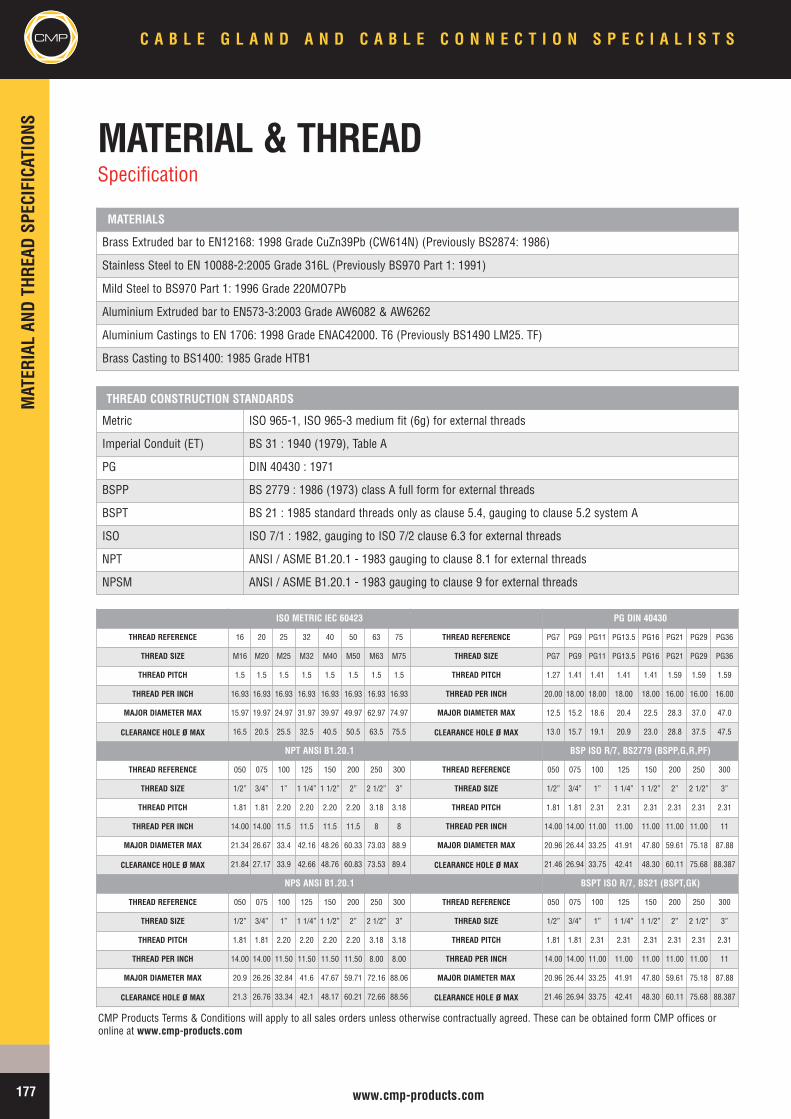
CMP C A B L E G L A N D A N D C A B L E C O N N E C T I O N S P E C I A L I S T S
177 www.cmp-products.com
MAT
ERIALAN
DTH
READ
SPEC
IFICAT
IONS MATERIAL & THREAD
Specification
Metric ISO 965-1, ISO 965-3 medium fit (6g) for external threads
Imperial Conduit (ET) BS 31 : 1940 (1979), Table A
PG DIN 40430 : 1971
BSPP BS 2779 : 1986 (1973) class A full form for external threads
BSPT BS 21 : 1985 standard threads only as clause 5.4, gauging to clause 5.2 system A
ISO ISO 7/1 : 1982, gauging to ISO 7/2 clause 6.3 for external threads
NPT ANSI / ASME B1.20.1 - 1983 gauging to clause 8.1 for external threads
NPSM ANSI / ASME B1.20.1 - 1983 gauging to clause 9 for external threads
Brass Extruded bar to EN12168: 1998 Grade CuZn39Pb (CW614N) (Previously BS2874: 1986)
Stainless Steel to EN 10088-2:2005 Grade 316L (Previously BS970 Part 1: 1991)
Mild Steel to BS970 Part 1: 1996 Grade 220MO7Pb
Aluminium Extruded bar to EN573-3:2003 Grade AW6082 & AW6262
Aluminium Castings to EN 1706: 1998 Grade ENAC42000. T6 (Previously BS1490 LM25. TF)
Brass Casting to BS1400: 1985 Grade HTB1
MATERIALS
THREAD CONSTRUCTION STANDARDS
ISO METRIC IEC 60423 PG DIN 40430
THREAD REFERENCE 16 20 25 32 40 50 63 75 THREAD REFERENCE PG7 PG9 PG11 PG13.5 PG16 PG21 PG29 PG36
THREAD SIZE M16 M20 M25 M32 M40 M50 M63 M75 THREAD SIZE PG7 PG9 PG11 PG13.5 PG16 PG21 PG29 PG36
THREAD PITCH 1.5 1.5 1.5 1.5 1.5 1.5 1.5 1.5 THREAD PITCH 1.27 1.41 1.41 1.41 1.41 1.59 1.59 1.59
THREAD PER INCH 16.93 16.93 16.93 16.93 16.93 16.93 16.93 16.93 THREAD PER INCH 20.00 18.00 18.00 18.00 18.00 16.00 16.00 16.00
MAJOR DIAMETER MAX 15.97 19.97 24.97 31.97 39.97 49.97 62.97 74.97 MAJOR DIAMETER MAX 12.5 15.2 18.6 20.4 22.5 28.3 37.0 47.0
CLEARANCE HOLE ø MAX 16.5 20.5 25.5 32.5 40.5 50.5 63.5 75.5 CLEARANCE HOLE ø MAX 13.0 15.7 19.1 20.9 23.0 28.8 37.5 47.5
NPT ANSI B1.20.1 BSP ISO R/7, BS2779 (BSPP,G,R,PF)
THREAD REFERENCE 050 075 100 125 150 200 250 300 THREAD REFERENCE 050 075 100 125 150 200 250 300
THREAD SIZE 1/2” 3/4” 1” 1 1/4” 1 1/2” 2” 2 1/2” 3” THREAD SIZE 1/2” 3/4” 1” 1 1/4” 1 1/2” 2” 2 1/2” 3”
THREAD PITCH 1.81 1.81 2.20 2.20 2.20 2.20 3.18 3.18 THREAD PITCH 1.81 1.81 2.31 2.31 2.31 2.31 2.31 2.31
THREAD PER INCH 14.00 14.00 11.5 11.5 11.5 11.5 8 8 THREAD PER INCH 14.00 14.00 11.00 11.00 11.00 11.00 11.00 11
MAJOR DIAMETER MAX 21.34 26.67 33.4 42.16 48.26 60.33 73.03 88.9 MAJOR DIAMETER MAX 20.96 26.44 33.25 41.91 47.80 59.61 75.18 87.88
CLEARANCE HOLE ø MAX 21.84 27.17 33.9 42.66 48.76 60.83 73.53 89.4 CLEARANCE HOLE ø MAX 21.46 26.94 33.75 42.41 48.30 60.11 75.68 88.387
NPS ANSI B1.20.1 BSPT ISO R/7, BS21 (BSPT,GK)
THREAD REFERENCE 050 075 100 125 150 200 250 300 THREAD REFERENCE 050 075 100 125 150 200 250 300
THREAD SIZE 1/2” 3/4” 1” 1 1/4” 1 1/2” 2” 2 1/2” 3” THREAD SIZE 1/2” 3/4” 1” 1 1/4” 1 1/2” 2” 2 1/2” 3”
THREAD PITCH 1.81 1.81 2.20 2.20 2.20 2.20 3.18 3.18 THREAD PITCH 1.81 1.81 2.31 2.31 2.31 2.31 2.31 2.31
THREAD PER INCH 14.00 14.00 11.50 11.50 11.50 11.50 8.00 8.00 THREAD PER INCH 14.00 14.00 11.00 11.00 11.00 11.00 11.00 11
MAJOR DIAMETER MAX 20.9 26.26 32.84 41.6 47.67 59.71 72.16 88.06 MAJOR DIAMETER MAX 20.96 26.44 33.25 41.91 47.80 59.61 75.18 87.88
CLEARANCE HOLE ø MAX 21.3 26.76 33.34 42.1 48.17 60.21 72.66 88.56 CLEARANCE HOLE ø MAX 21.46 26.94 33.75 42.41 48.30 60.11 75.68 88.387
CMP Products Terms & Conditions will apply to all sales orders unless otherwise contractually agreed. These can be obtained form CMP offices oronline at www.cmp-products.com
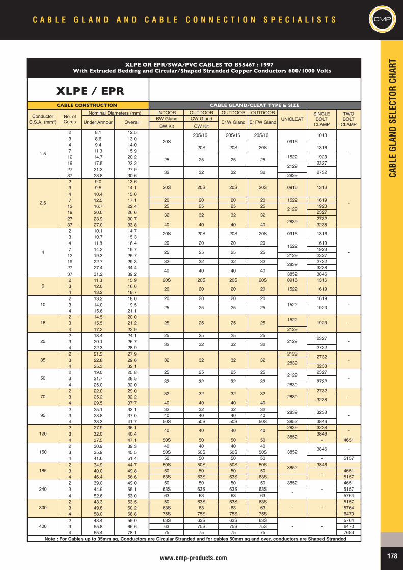
CABL
EGL
ANDSE
LECT
ORCH
ART
178www.cmp-products.com
C A B L E G L A N D A N D C A B L E C O N N E C T I O N S P E C I A L I S T S CMP
INDOOR OUTDOOR OUTDOOR OUTDOORBW Gland CW GlandBW Kit CW Kit
2 8.1 12.53 8.6 13.04 9.4 14.07 11.3 15.912 14.7 20.2 1522 192319 17.5 23.2 232727 21.3 27.937 23.8 30.6 28392 9.0 13.63 9.5 14.14 10.4 15.07 12.5 17.1 20 20 20 20 1522 161912 16.7 22.4 25 25 25 25 192319 20.0 26.6 232727 23.9 30.7 273237 27.0 33.8 40 40 40 40 32382 10.1 14.73 10.7 15.34 11.8 16.4 20 20 20 20 16197 14.2 19.7 192312 19.3 25.7 2129 232719 22.7 29.3 32 32 32 32 273227 27.4 34.4 323837 31.2 39.2 3852 38462 11.3 15.9 20S 20S 20S 20S 0916 13163 12.0 16.64 13.2 18.72 13.2 18.0 20 20 20 20 16193 14.0 19.54 15.6 21.12 14.5 20.03 15.5 21.2 25 25 25 254 17.2 22.9 21292 18.4 24.1 25 25 25 253 20.1 26.74 22.3 28.9 27322 21.3 27.9 21293 22.8 29.6 32 32 32 324 25.3 32.1 32382 19.0 25.8 25 25 25 25 23273 21.7 28.54 25.0 32.0 28392 22.0 29.0 27323 25.2 32.24 29.5 37.7 40 40 40 402 25.1 33.1 32 32 32 323 28.8 37.0 40 40 40 404 33.3 41.7 50S 50S 50S 50S 3852 38462 27.9 36.1 2839 32383 32.0 40.4 38464 37.5 47.1 50S 50 50 50 - 46512 30.9 39.3 40 40 40 403 35.9 45.5 50S 50S 50S 50S4 41.6 51.4 50 50 50 50 - 51572 34.9 44.7 50S 50S 50S 50S 38463 40.0 49.8 50 50 50 50 46514 46.4 56.6 63S 63S 63S 63S - 51572 39.0 49.0 50 50 50 50 3852 46513 44.9 55.1 63S 63S 63S 63S 51574 52.6 63.0 63 63 63 63 57642 43.3 53.5 50 63S 63S 63S 51573 49.8 60.2 63S 63 63 63 57644 58.0 68.8 75S 75S 75S 75S 64702 48.4 59.0 63S 63S 63S 63S 57643 55.8 66.6 63 75S 75S 75S 64704 65.4 78.1 75 75 75 75 7683
Note : For Cables up to 35mm sq, Conductors are Circular Stranded and for cables 50mm sq and over, conductors are Shaped Stranded
XLPE OR EPR/SWA/PVC CABLES TO BS5467 : 1997
-
-
-
2129
2839
3238
2839
-
-
-
-
2839
21292732
-
-
3852 3846 -
-
3238
3852
2327
2732
-
-
-
-
-
-
3852
1619
1522 1923
1522 1923
40 40 40
091620S/16 20S/16 20S/16
2129
1522
2129
2839
32 32 32
32 32 32
25 25 25
32 32 32
25 25 25
20 20 20
40 40 40
32 32 32
20S 20S 20S
25
32 32
20S 20S 20S
2839
With Extruded Bedding and Circular/Shaped Stranded Copper Conductors 600/1000 Volts
20S
25
1013
1316
32
20S 20S
25
UNICLEATTWOBOLTCLAMP
SINGLEBOLTCLAMP
1522
2732
0916 1316
0916 1316
-
CABLE CONSTRUCTION
No. ofCores
Nominal Diameters (mm)
Under Armour OverallConductorC.S.A. (mm2)
32
20S
25
20S
25
32
32
32
40
E1W Gland E1FW Gland
40
20
25
32
20S
1.5
2.5
4
6
95
120
10
16
25
35
400
-
CABLE GLAND/CLEAT TYPE & SIZE
150
185
240
300
50
70
XLPE / EPR
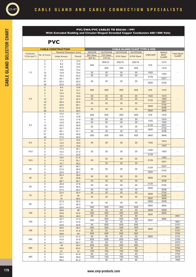
CMPCA
BLEGL
ANDSE
LECT
ORCH
ART
C A B L E G L A N D A N D C A B L E C O N N E C T I O N S P E C I A L I S T S
179 www.cmp-products.com
INDOOR OUTDOOR OUTDOOR OUTDOORBW Gland CW Gland
BW Kit CW Kit2 7.7 12.33 8.2 12.84 8.9 13.57 10.6 15.212 13.9 19.4 20 20 20 20 152219 16.5 22.2 25 25 25 2527 20.1 26.7 232737 22.4 29.248 25.9 32.92 9.0 13.63 9.5 14.14 10.4 15.07 12.5 18.0 20 20 20 20 1522 161912 16.7 22.4 25 25 25 25 192319 20.0 26.6 232727 23.9 30.7 273237 27.0 34.0 323848 31.3 39.5 3852 38462 10.5 15.13 11.2 15.84 12.3 17.8 20 20 20 20 16197 14.8 20.5 25 25 25 25 192312 20.2 26.8 2129 232719 23.7 30.5 273227 29.1 37.1 40 40 40 40 323837 32.6 40.848 37.6 46.02 11.7 16.53 12.5 18.04 13.7 19.2 19232 14.4 20.13 15.5 21.24 17.1 22.8 21292 16.2 21.9 19233 17.4 23.14 19.7 26.3 32 32 322 20.1 26.7 23273 21.6 28.24 23.9 30.7 28392 22.4 29.23 24 30.84 26.7 33.7 40 40 40 40 32382 20.8 27.8 21293 23.5 30.54 27.4 35.4 40 40 40 40 32382 23.4 30.4 32 32 32 32 27323 27 35 32384 31 39.2 3852 38462 27.3 35.5 2839 32383 31.1 39.34 35.9 44.3 50S 50S 50S 50S2 29.6 38 40 40 40 40 2839 32383 33.8 42.2 50S 50S 50S 50S 38464 39.5 49.3 50 50 50 50 - 46512 32.7 41.3 50S 50S 50S 3846 -3 37.7 47.5 50 50 50 46514 43.6 53.6 50 63S 63S 63S - 51572 36.6 46.4 50S 50S 50S 50S 46513 41.9 51.9 50 50 50 50 51574 48.8 59 63S 63S 63S 63S - 57642 41.2 51.2 50 50 50 50 3852 51573 47.6 57.8 63S 63S 63S 63S 57644 55.1 65.7 63 63 63 63 64702 46 56.4 63S 63S 63S 63S 51573 52.6 63.2 63 63 63 63 57644 61 72 75S 75S 75S 75S 70762 51.1 61.9 63 63 63 63 57643 58.6 69.6 75S 75S 75S 75S 64704 68.4 81.3 - 90 90 90 7683
32
32
185
240
32
40
40
50S
300
400
50
70
120
150
95
10.0
16.0
25
35
1.5
2.5
4.0
6.0
20S/1620S
50S
32
32
40
20S
32
20S
20S
20S
32
32
40
20S
32
50S
20
25
25
32
32
32
40
40
20S/16
20S
32
20S
32
40
20S
32
50S
20
25
25
32
32
32
40
40
916
2129
2839
916
2129
2839
916
1522
2839
3852
1522
1522
2129
2129
2839
2839
2839
3852
3852
3852
3852
-
-
-
1013
1316
1923
2732
1316
1316
3846
1619
1923
2327
2732
2732
-
-
-
-
-
-
-
-
-
2732
-
20
25
25
-
-
-
-
Under Armour Overall
PVC/SWA/PVC CABLES TO BS6346 : 1997With Extruded Bedding and Circular/Shaped Stranded Copper Conductors 600/1000 Volts
PVC
E1W Gland E1FW Gland
CABLE CONSTRUCTION CABLE GLAND/CLEAT TYPE & SIZE
ConductorC.S.A. (mm 2 )
No. of CoresNominal Diameters (mm)
UNICLEATSINGLEBOLT
CLAMP
TWO BOLTCLAMP
20S/16
20S
32
20S
32
40
20S
32
50S
20
25
25
40
32
32
32
40
-
-
-
3846
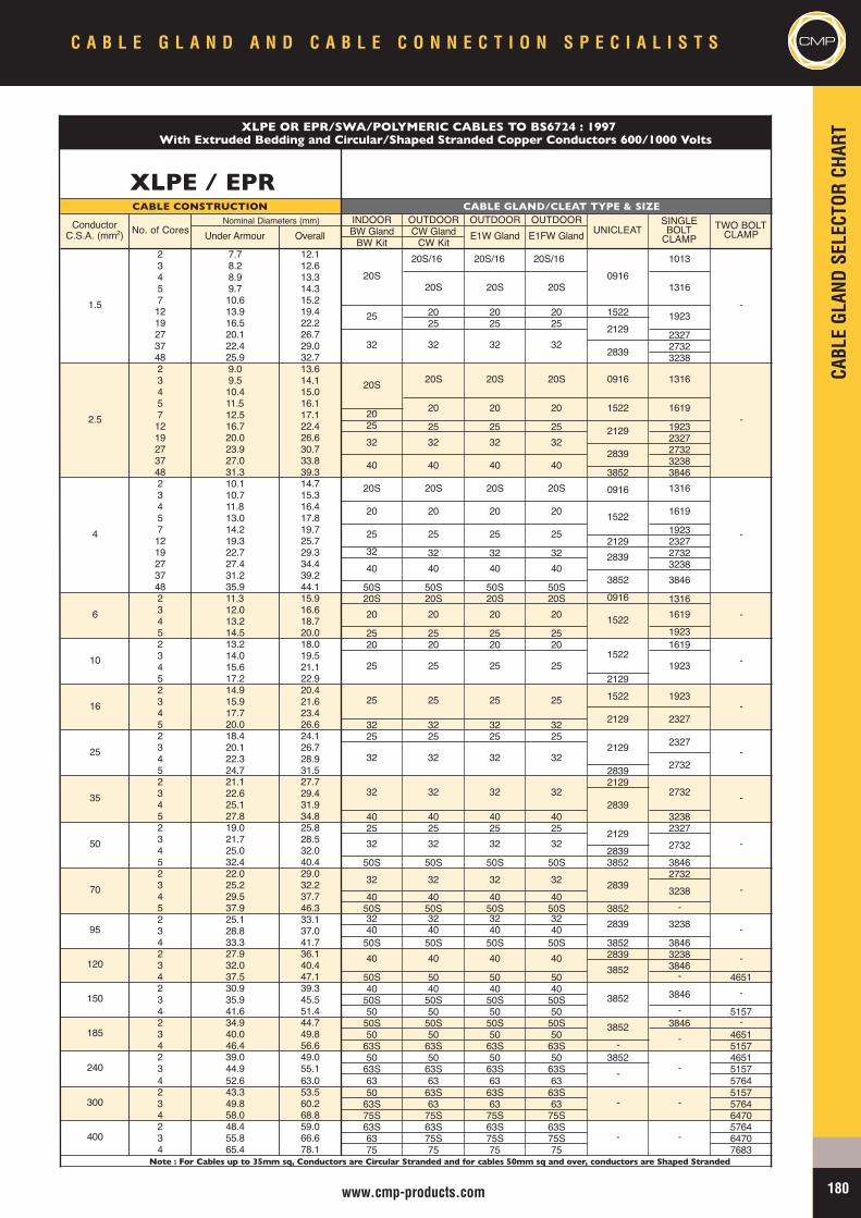
CABL
EGL
ANDSE
LECT
ORCH
ART
180www.cmp-products.com
CMPC A B L E G L A N D A N D C A B L E C O N N E C T I O N S P E C I A L I S T S
INDOOR OUTDOOR OUTDOOR OUTDOORBW Gland CW GlandBW Kit CW Kit
2 7.7 12.13 8.2 12.64 8.9 13.35 9.7 14.37 10.6 15.212 13.9 19.4 20 20 20 152219 16.5 22.2 25 25 2527 20.1 26.7 232737 22.4 29.0 273248 25.9 32.7 32382 9.0 13.63 9.5 14.14 10.4 15.05 11.5 16.17 12.5 17.1 2012 16.7 22.4 25 25 25 25 192319 20.0 26.6 232727 23.9 30.7 273237 27.0 33.8 323848 31.3 39.3 3852 38462 10.1 14.73 10.7 15.34 11.8 16.45 13.0 17.87 14.2 19.7 192312 19.3 25.7 2129 232719 22.7 29.3 32 32 32 32 273227 27.4 34.4 323837 31.2 39.248 35.9 44.1 50S 50S 50S 50S2 11.3 15.9 20S 20S 20S 20S 0916 13163 12.0 16.64 13.2 18.75 14.5 20.0 25 25 25 25 19232 13.2 18.0 20 20 20 20 16193 14.0 19.54 15.6 21.15 17.2 22.9 21292 14.9 20.43 15.9 21.64 17.7 23.45 20.0 26.6 32 32 32 322 18.4 24.1 25 25 25 253 20.1 26.74 22.3 28.95 24.7 31.5 28392 21.1 27.7 21293 22.6 29.44 25.1 31.95 27.8 34.8 40 40 40 40 32382 19.0 25.8 25 25 25 25 23273 21.7 28.54 25.0 32.0 28395 32.4 40.4 50S 50S 50S 50S 3852 38462 22.0 29.0 27323 25.2 32.24 29.5 37.7 40 40 40 405 37.9 46.3 50S 50S 50S 50S 3852 -2 25.1 33.1 32 32 32 323 28.8 37.0 40 40 40 404 33.3 41.7 50S 50S 50S 50S 3852 38462 27.9 36.1 2839 32383 32.0 40.4 38464 37.5 47.1 50S 50 50 50 - 46512 30.9 39.3 40 40 40 403 35.9 45.5 50S 50S 50S 50S4 41.6 51.4 50 50 50 50 - 51572 34.9 44.7 50S 50S 50S 50S 3846 -3 40.0 49.8 50 50 50 50 46514 46.4 56.6 63S 63S 63S 63S - 51572 39.0 49.0 50 50 50 50 3852 46513 44.9 55.1 63S 63S 63S 63S 51574 52.6 63.0 63 63 63 63 57642 43.3 53.5 50 63S 63S 63S 51573 49.8 60.2 63S 63 63 63 57644 58.0 68.8 75S 75S 75S 75S 64702 48.4 59.0 63S 63S 63S 63S 57643 55.8 66.6 63 75S 75S 75S 64704 65.4 78.1 75 75 75 75 7683
20S
20
25
40
240
300
400
20S/16
20S
32
20S
20
32
40
95
120
150
185
25
35
50
70
4
6
10
16
2.5
UNICLEAT
40
ConductorC.S.A. (mm2) No. of Cores
Nominal Diameters (mm)CABLE CONSTRUCTION CABLE GLAND/CLEAT TYPE & SIZE
1.5
Under Armour Overall E1W Gland
32
20S 20S
32 32
20S
E1FW GlandSINGLEBOLTCLAMP
TWO BOLTCLAMP
-
1013
1316
2129
2839
-
-
2839
0916
1522
-
1923
0916 1316
-
-
-
-
-
-
-
-
-
-
3846
3238
-
-
3852
2839
3852
3852
-
-
-
-
1522
32382839
1923
1923
1522
2839
1522
2839
40 40
32 32 32
32 32 32
20 20
40
1522
25
25
32
32
40
2020
25 25 25
20S 20S
25 25 25
20 20 20
20S 20S
32 32 32
20 20
20S
25
XLPE OR EPR/SWA/POLYMERIC CABLES TO BS6724 : 1997
091620S/16 20S/16
With Extruded Bedding and Circular/Shaped Stranded Copper Conductors 600/1000 Volts
XLPE / EPR
1619
1619
2732
3846
2327
2732
2327
1619
1316
2129
25 25 25
2129
40 40 403852
20S
32 32 322129
Note : For Cables up to 35mm sq, Conductors are Circular Stranded and for cables 50mm sq and over, conductors are Shaped Stranded
32 32 32
2732
32
322129
40 40
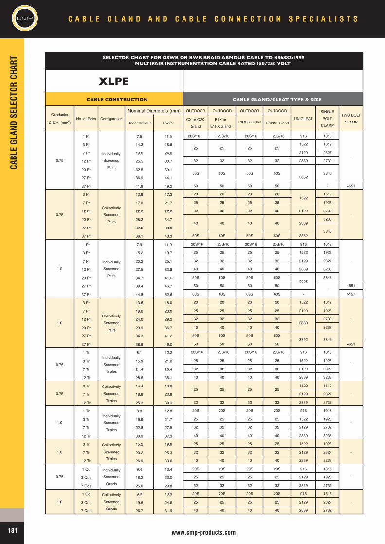
CMPCA
BLEGL
ANDSE
LECT
ORCH
ART
C A B L E G L A N D A N D C A B L E C O N N E C T I O N S P E C I A L I S T S
181 www.cmp-products.com
OUTDOOR OUTDOOR OUTDOOR OUTDOOR
1 Pr 7.5 11.5 20S/16 20S/16 20S/16 20S/16 916 1013
3 Pr 14.2 18.6 1522 1619
7 Pr 19.0 24.0 2129 2327
12 Pr 25.5 30.7 32 32 32 32 2839 2732
20 Pr 32.5 39.1
27 Pr 36.9 44.1
37 Pr 41.8 49.2 50 50 50 50 - 4651
3 Pr 12.9 17.3 20 20 20 20 1619
7 Pr 17.0 21.7 25 25 25 25 1923
12 Pr 22.6 27.6 32 32 32 32 2129 2732
20 Pr 28.2 34.7 3238
27 Pr 32.0 38.8
37 Pr 36.1 43.3 50S 50S 50S 50S 3852
1 Pr 7.9 11.9 20S/16 20S/16 20S/16 20S/16 916 1013
3 Pr 15.2 19.7 25 25 25 25 1522 1923
7 Pr 20.2 25.1 32 32 32 32 2129 2327
12 Pr 27.5 33.8 40 40 40 40 2839 3238
20 Pr 34.7 41.6 50S 50S 50S 50S 3846
27 Pr 39.4 46.7 50 50 50 50 4651
37 Pr 44.8 52.6 63S 63S 63S 63S - 5157
3 Pr 13.6 18.0 20 20 20 20 1522 1619
7 Pr 18.0 23.0 25 25 25 25 2129 1923
12 Pr 24.0 29.2 32 32 32 32 2732
20 Pr 29.9 36.7 40 40 40 40 3238
27 Pr 34.3 41.2 50S 50S 50S 50S
37 Pr 38.6 46.0 50 50 50 50 4651
1 Tr 8.1 12.2 20S/16 20S/16 20S/16 20S/16 916 1013
3 Tr 15.9 21.0 25 25 25 25 1522 1923
7 Tr 21.4 26.4 32 32 32 32 2129 2327
12 Tr 28.6 35.1 40 40 40 40 2839 3238
3 Tr 14.4 18.8 1522 1619
7 Tr 18.8 23.8 2129 2327
12 Tr 25.3 30.9 32 32 32 32 2839 2732
1 Tr 8.8 12.8 20S 20S 20S 20S 916 1013
3 Tr 16.9 21.7 25 25 25 25 1522 1923
7 Tr 22.8 27.8 32 32 32 32 2129 2732
12 Tr 30.9 37.3 40 40 40 40 2839 3238
3 Tr 15.2 19.8 25 25 25 25 1522 1923
7 Tr 20.2 25.3 32 32 32 32 2129 2327
12 Tr 26.9 33.6 40 40 40 40 2839 3238
1 Qd 9.4 13.4 20S 20S 20S 20S 916 1316
3 Qds 18.2 23.0 25 25 25 25 2129 1923
7 Qds 25.0 29.8 32 32 32 32 2839 2732
1 Qd 9.9 13.9 20S 20S 20S 20S 916 1316
3 Qds 19.6 24.6 25 25 25 25 2129 2327
7 Qds 26.7 31.9 40 40 40 40 2839 2732
-
-
-
-
-
-
-
-
-
-
2839
3852
3846
3846
-
3846
3852
1522
2839
3852
50S
40
25 25 25
0.75
Individually
Screened
Pairs
Collectively
Screened
Pairs
0.75
Nominal Diameters (mm)Configuration
CABLE CONSTRUCTION CABLE GLAND/CLEAT TYPE & SIZE
Conductor
C.S.A. (mm2)No. of Pairs UNICLEAT
SINGLE
BOLT
CLAMP
TWO BOLT
CLAMPUnder Armour
SELECTOR CHART FOR GSWB OR BWB BRAID ARMOUR CABLE TO BS6883:1999MULTIPAIR INSTRUMENTATION CABLE RATED 150/250 VOLT
XLPE
PX2KX GlandCX or C2K
Gland
Individually
Screened
Pairs
OverallE1X or
E1FX Gland
25
40
25 25 25
Collectively
Screened
Pairs
Individually
Screened
Triples
Collectively
Screened
Triples
T3CDS Gland
25
40 40
50S 50S 50S
Collectively
Screened
Triples
Individually
Screened
Triples
Individually
Screened
Quads
Collectively
Screened
Quads
1.0
1.0
0.75
0.75
1.0
1.0
0.75
1.0
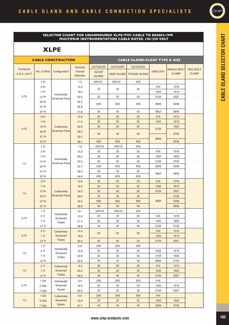
CABL
EGL
ANDSE
LECT
ORCH
ART
182www.cmp-products.com
C A B L E G L A N D A N D C A B L E C O N N E C T I O N S P E C I A L I S T S CMP
OUTDOOR OUTDOOR OUTDOOR
1 Pr 7.5 20S/16 20S/16 20S - -
3 Pr 14.2 916 1316
7 Pr 19.0 1522 1619
12 Pr 25.5 32 32 32 2129 2327
20 Pr 32.5
27 Pr 36.9
37 Pr 41.8 50 50 50 3852 3846
3 Pr 12.9 20 20 20 916 1013
7 Pr 17.0 25 25 25 1522 1619
12 Pr 22.6 32 32 32 1923
20 Pr 28.2
27 Pr 32.0
37 Pr 36.1 50S 50S 50S 3238
1 Pr 7.9 20S/16 20S/16 20S - -
3 Pr 15.2 25 25 25 916 1316
7 Pr 20.2 32 32 32 1522 1923
12 Pr 27.5 40 40 40 2129 2732
20 Pr 34.7 50S 50S 50S 2839 3238
27 Pr 39.4 50 50 50
37 Pr 44.8 63S 63S 63S
3 Pr 13.6 20 20 20 916 1316
7 Pr 18.0 25 25 25 1522 1619
12 Pr 24.0 32 32 32 2129 2327
20 Pr 29.9 40 40 40 2732
27 Pr 34.3 50S 50S 50S 3238
37 Pr 38.6 50 50 50 3846
1 Tr 8.1 20S/16 20S/16 20S - -
3 Tr 15.9 25 25 25 916 1316
7 Tr 21.4 32 32 32 1522 1923
12 Tr 28.6 40 40 40 2129 2732
3 Tr 14.4 916 1316
7 Tr 18.8 1522 1619
12 Tr 25.3 32 32 32 2129 2327
1 Tr 8.8 20S 20S 20S - -
3 Tr 16.9 25 25 25 1522 1619
7 Tr 22.8 32 32 32 2129 1923
12 Tr 30.9 40 40 40 2839 2732
3 Tr 15.2 25 25 25 916 1316
7 Tr 20.2 32 32 32 1522 1923
12 Tr 26.9 40 40 40 2129 2327
1 Qd 9.4 20S 20S 20S 916 -
3 Qds 18.2 25 25 25 1522 1619
7 Qds 25.0 32 32 32 2129 2327
1 Qd 9.9 20S 20S 20S 916 -
3 Qds 19.6 25 25 25 1522 1923
7 Qds 31.7 40 40 40 2839 2732
-
-
-
-
-
-
-
-
-
3852
2839
3238
2732
3846
2839
2129
2839
-
40 40
25 25
25 25
50S 50S
25
50S
40
25
1.0
1.0
0.75
1.0
1.0
1.0
0.75
0.75
CollectivelyScreenedTriples
IndividuallyScreenedTriples
IndividuallyScreenedQuads
CollectivelyScreenedQuads
IndividuallyScreened Pairs
CollectivelyScreened Pairs
IndividuallyScreenedTriples
CollectivelyScreenedTriples
SELECTOR CHART FOR UNARMOURED XLPE/PVC CABLE TO BS6883:1999MULTIPAIR INSTRUMENTATION CABLE RATED 150/250 VOLT
XLPE
CABLE GLAND/CLEAT TYPE & SIZE
ConductorC.S.A. (mm2)
No. of Pairs UNICLEATSINGLE BOLTCLAMP
TWO BOLTCLAMPA2/A2F
GLANDSS2K GLAND PXSS2K GLAND
Configuration
CABLE CONSTRUCTION
0.75Individually
Screened Pairs
CollectivelyScreened Pairs
0.75
NominalOverallDiameter
CMP
www.cmp-products.comTPC 2007 – Issue 09/07
Available from:For any other requirement not listed withinthe CMP standard catalogue range, please feelfree to convey your requirements to the nearestoffice detailed above, as CMP prides itself inhaving the ability and flexibility to providesolutions that meet the very needs of industry.Whether your application is for General PurposeIndustrial, Ordinary Locations, Marine and WetLocations, or Hazardous Locations, CMPdelivers the solution at the right place, the righttime and the right price.
NEWCASTLE (Headquarters)CMP ProductsGlasshouse Street, St PetersNewcastle Upon TyneNE6 1BS, EnglandTel: +44 191 265 7411Fax: +44 191 265 0581E-Mail: [email protected]
DUBAI (British Engines (Middle East) FZE)CMP Products Middle East OfficeP.O. Box 61363, Jebel Ali Free ZoneJebel Ali, Dubai, United Arab EmiratesTel: +971 4 887 1012Fax: +971 4 887 1015E-Mail: [email protected]
SINGAPORECMP Products (S.E.A) Pte Ltd.21 Toh Guan Road East, #09-03,Toh Guan CentreSingapore 608609Tel: +65 6466 6180Fax: +65 6466 9891E-Mail: [email protected]
HOUSTON (British Engines Texas Inc)CMP Products5829W Sam Houston Parkway NSuite 205 Houston, Texas 77041, USATel: +1 713 462 2073Fax: +1 713 462 2076E-Mail: [email protected]
SHANGHAICMP Products (Representative Office)Room 2407, Building C, Thompson CentreNo 188 Zhangyang Road, Pudong DistrictShanghai, 200120 P.R. ChinaTel: +86 21 5054 0096Fax: +86 21 5054 0676E-Mail: [email protected]
PUSANCMP Products (Korea) Ltd8-810, Digital Valley,132-7, Gamjeon-dong, Sasang-guPusan, South KoreaTel: +82 51 317 3147Fax: +82 51 317 3148E-Mail: [email protected]
PERTH, WACMP ProductsUnit 3 - 22 Harlond AvenueMalaga, WA 6090AustraliaTel: +61 (0) 447 440 370Email: [email protected]
www.cmp-products.com www.cmp-products.com.cn www.cmp-products.ru