CMD Series User's Manual 2020
9
We bring better air to life 2020 USER’S MANUAL HALF METAL CEILING FAN Thank you for choosing half metal ceiling mounted fan. Please read and save this user's manual for future reference. Read carefully before attempting to assemble, install, operate or maintain the product described. Protect yourself and others by observing all safety information. Failure to comply with instructions could result in personal injury and property damage. CMD 160D CMD 160A CMD 210A CMD Series
Transcript of CMD Series User's Manual 2020

We bring better air to life
2020
USER’S MANUAL
HALF METAL CEILING FANThank you for choosing half metal ceiling mounted fan. Please
read and save this user's manual for future reference. Read
carefully before attempting to assemble, install, operate or
maintain the product described. Protect yourself and others by
observing all safety information. Failure to comply with instructions
could result in personal injury and property damage.
CMD 160D
CMD 160A
CMD 210A
CMD Series
01www.breeze.com.vn | [email protected]
We bring better air to life
USER’S MANUALCMD SERIES
1. GENERAL SAFETY INFORMATION
Ÿ Please read the user’s manual carefully prior to installing and operating the unit.
Ÿ This user’s manual is the primary operating document intended for technical, maintenance and operations staff.
Ÿ All user’s manual requirements as well as the provisions of all the applicable local and national construction, electrical and
technical norms and standards must be observed when installing and operating the unit.
Ÿ The warnings contained in the user’s manual must be considered most seriously since they contain vital personal safety
information.
Ÿ Failure to follow the rules and safety precautions noted in this user’s manual may result in an injury or unit damage.
After a careful reading of the manual, keep it for the entire service life of the unit.
Ÿ While transferring the unit control, the user’s manual must be turned over to the receiving operator.
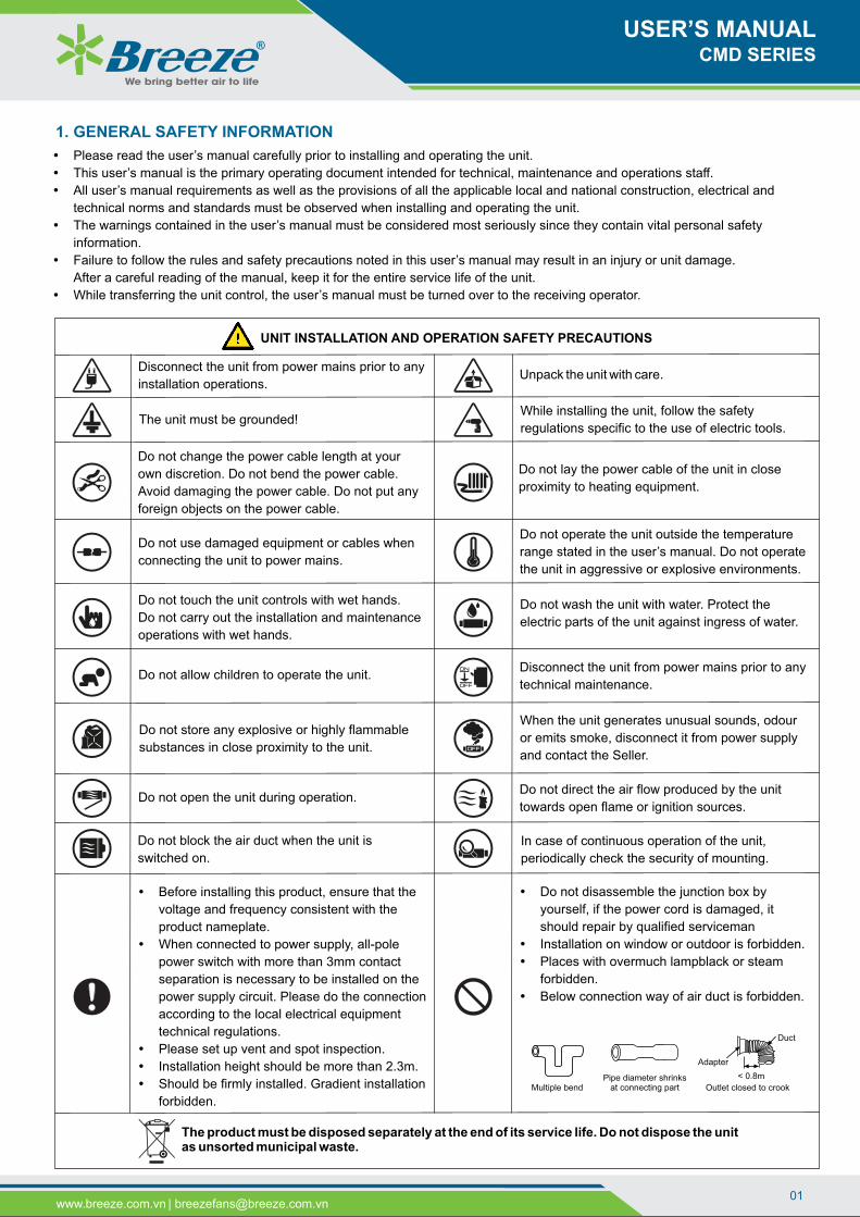
Disconnect the unit from power mains prior to any
installation operations.
While installing the unit, follow the safety
regulations specific to the use of electric tools.
Do not lay the power cable of the unit in close
proximity to heating equipment.
Do not change the power cable length at your
own discretion. Do not bend the power cable.
Avoid damaging the power cable. Do not put any
foreign objects on the power cable.
Do not use damaged equipment or cables when
connecting the unit to power mains.
Do not operate the unit outside the temperature
range stated in the user’s manual. Do not operate
the unit in aggressive or explosive environments.
Do not touch the unit controls with wet hands.
Do not carry out the installation and maintenance
operations with wet hands.
Do not wash the unit with water. Protect the
electric parts of the unit against ingress of water.
Disconnect the unit from power mains prior to any
technical maintenance.
Do not store any explosive or highly flammable
substances in close proximity to the unit.
When the unit generates unusual sounds, odour
or emits smoke, disconnect it from power supply
and contact the Seller.
Do not direct the air flow produced by the unit
towards open flame or ignition sources.
Do not block the air duct when the unit is
switched on.
In case of continuous operation of the unit,
periodically check the security of mounting.
The product must be disposed separately at the end of its service life. Do not dispose the unit as unsorted municipal waste.
Do not allow children to operate the unit.
The unit must be grounded!
Do not open the unit during operation.
Unpack the unit with care.
Multiple bendPipe diameter shrinks
at connecting part
< 0.8m
Adapter
Duct
Outlet closed to crook
UNIT INSTALLATION AND OPERATION SAFETY PRECAUTIONS
Ÿ Before installing this product, ensure that the
voltage and frequency consistent with the
product nameplate.
Ÿ When connected to power supply, all-pole
power switch with more than 3mm contact
separation is necessary to be installed on the
power supply circuit. Please do the connection
according to the local electrical equipment
technical regulations.
Ÿ Please set up vent and spot inspection.
Ÿ Installation height should be more than 2.3m.
Ÿ Should be firmly installed. Gradient installation
forbidden.
Ÿ Do not disassemble the junction box by
yourself, if the power cord is damaged, it
should repair by qualified serviceman
Ÿ Installation on window or outdoor is forbidden.
Ÿ Places with overmuch lampblack or steam
forbidden.
Ÿ Below connection way of air duct is forbidden.

2. PRODUCTS OVERVIEW
www.breeze.com.vn | [email protected]
We bring better air to life
The CMD series is designed luxury ceiling exhaust fan which use as ducted and unducted ceiling mounted extractions.
The CMD series are offered with motor types:
Ÿ CMD-A series: AC motor.
Ÿ CMD-D series: DC motor.
Material:
Ÿ Casing: Half metal and powder coated.
Ÿ Impeller: ABS polymer and high efficiency forward curve centrifugal impeller driven with sealed for by long life bearing.
Ÿ Motor: 100% copper coil and fitted with high quality ball bearing, high efficiency, low noise, maintenance free and long service life.
Equipped with thermal overload protection.
Ÿ Standard motor range is protected to IP 44, class B insulation.
Feature:
Ÿ Be able to speed controllable.
Ÿ Low noise levels, including valve one-way
Application: Shopping malls, entertainment and residential area, bathroom, bedroom, office, living room, store, toilets, hotels and
exhaust ventilation.
1. Half Metal Casing
2. Motor Frame
3. Centrifugal Casing
4. Forward Curve Impeller
5. Screws
Half metal ceiling mounted fan with standard
motor are suitable for ventilation of:
• Clean air
• Slightly dusty and greasy air
• Slightly aggressive gases and vapour
• Mediums up to an atmospheric density of 1.2 kg/m3
• Mediums with a temperature of -20°C up to +40°C
• Mediums up to a max. Humidity of 85%
• The ambient temperature of the motor must be between -20°C and +40°C make sure and adhere to the specifications of the
motor manufacturer.
Construction.
The half metal ceiling mounted fan consists of the following main parts:
3. PERFORMANCE CURVE
4. PERFORMANCE PARAMETERS
Voltage(V/P/Hz)
220/1/50
220/1/50
220/1/50
Power(W)
6
22
30
Speed(rpm/min)
900
1020
1020
NoisedBA
(at 3m)
28
29
33
Max.Air Volume
3(m /h)
160
160
210
Model
CMD 160D
CMD 160A
CMD 210A
240x240
210X210
240X240
Installation(mm)
Weight(Kg)
4.0
3.0
3.5
Max.Pressure
(Pa)
120
120
150
60
30
90
120
30 60 90 120 150 180
CMD 160DPa
3m /h
150
0
60
30
90
120
30 60 90 120 150 180
CMD 160APa
3m /h
150
0
60
30
90
120
50 100 150 200 250
CMD 210APa
3m /h
150
0
USER’S MANUALCMD SERIES
8
9
6. Terminal Electric Box
7. Louver
8. Valve One-Way
9. Outlet Duct

03
5. DIMENSION INFORMATION
Electric Connection
6. ELECTRIC INSTALLATION
• Check that supply is according to data on nameplate.
• Insert cable according to the instructions in the junction box and
seal it (Avoid water enter).The equipment connected ground for
motor protection according to the instructions - Unless the
guarantee isn’t accepted. Connect electric supply.
• After connecting the wiring, install the terminal cover with screws.
Wiring Diagram
www.breeze.com.vn | [email protected]
We bring better air to life
All dimensions in mm.
Model
CMD 160D
CMD 160A
CMD 210A
A
270
245
270
B
230
205
230
C
185
185
185
D
100
100
100
E
300
275
300
B
C
A
E
D
ACMotor
Black
Red
Brown
Capacity
Yellow Green
Terminals
Yellow Green
Brown
BlueN
L
FU
Fan
L 1
2
3
4
N
L
N
MCB
PE
AC ~
220-240V
50 Hz
DCMotor
Black
Red
Yellow Green
Terminals
Yellow Green
Brown
BlueN
L
FU
Control
PEPE
• The fan is designed for 220-240V/50Hz (single-phase).
• The fan shall be connected to power supply by means of insulated, durable and thermal-resistant cords (cables, wires).
• Electric wiring must be in accordance with technical connection regulations and local ordinances and national electric codes as
per enclosed wiring diagram in the terminal box or on the casing.
• The recommended wire cross section is minimum 0.75 mm2.
• The actual conductor cross-section selection must be based on its type, maximum permissible heating, insulation, length and
installation method (in the air, pipes or inside walls). Connect the cables to the terminal block incorporated inside the terminal
box located on the fan casing in compliance with the fan wiring diagram and the terminal designation. The terminal designations
are shown on the sticker inside the fan casing.
7. INSTALLATION METHOD
Ÿ Make a wooden frame and fix it on to the ceiling as picture reference.
Ÿ Install and enclose the fan casing in the wooden frame, and then fix it up firmly with 04 self-tapping screws.
Ÿ Connect the pipeline with the main part, and make it well-sealed with the self-adhesive tape (bandage). (Fix the ventilating pipeline
onto the ceiling, keeping the ventilating pipeline straight, without burden on the main part) no burden on the pipeline.
Ÿ After connecting the power supply, turn on the switch, check whether there is abnormal condition, and then place spring in the slot
hole to fix the panel.
Ÿ We must prevent the gas from the open airway or other firing equipment from back flowing into the room.
USER’S MANUALCMD SERIES

www.breeze.com.vn | [email protected]
We bring better air to life
Ceiling joist Wooden frame
Enhance piece
Fig 1.
Fig 2.
Outlet duct
Self-adhesive tape
Fig 3.
SpringLouver
Fig 4.
Wall
Louver
Duct Outlet
Fan
Constructor
Fig 5.
Before starting the unit, check the following:
• Confirm that building supply voltage matches the voltage for which the unit is wired.
• Check all piping and wiring penetrations
• Made by contractors for water tightness. All penetrations must be made watertight to prevent water damage to the unit and
building.
• Rotate the fan impeller manually to be sure that it is free to operate. Remove any dirt or debris that may have accumulated
during installation.
• Inspect all fasteners to ensure that none have loosened during shipment.
• Check all electrical connections for proper attachment.
• Check casing and ductwork, if accessible, for obstructions and foreign material that may damage the fan impeller.
Check
• The equipment type and arrangement should be verified as ordered at once when it arrives at the jobsite. When a discrepancy
is found, the local Breeze Sales Representative must be notified immediately so that corrective action may be investigated, also
verify electrical conformance to specifications. Unauthorized alterations and unauthorized backcharges will not be recognized by
Breeze Fan.
• After the unit has been assembled, installed and all utilities have been hooked up, the unit is now ready for operation.
8. OPERATION INSTRUCTION
Visual Inspection of Equipment
• Check that the mechanical assembly has been carried out properly
• Remove foreign bodies located in the suction and outflow areas and in the fan space
• Check that the electrical installation has been completed in accordance with regulations
• Does the mains voltage match the motor voltage specified on the rating plate?
• Is the motor protection system set correctly with regard to the motor's nominal current? The setting must be carried out in
accordance with the corresponding details contained on the motor output plate.
• Has the motor been connected correctly in accordance with the wiring diagram? The connection schematic supplied by the
motor suppliers applies for the connection of the motor.
Checks prior to initial start-up
Proceed with the fan's initial start-up in the following sequence:
USER’S MANUALCMD SERIES

www.breeze.com.vn | [email protected]
We bring better air to life
9. ROUTINE MAINTENANCE
• Regular maintenance is needed each year. The impeller blades require thorough cleaning once in 6 months.
• Before any maintenance work is undertaken:
o Stop fan in accordance to regulations and disconnect all poles from mains supply.
o Wait until impeller is stationary.
o Make sure that a restart is not possible
• Use only original spare parts tested and approved by the manufacturer.
• The following safety notes must be observed when maintaining the machine.
• Replace the ball bearings of the motor whenever the grease utilization period has elapsed in accordance with the maintenance
instructions of the manufacturer.
• The technical maintenance includes periodic cleaning of the surfaces from accumulated dust and dirt.
• Use a soft dry brush or a vacuum cleaner to remove dust.
• Only use usual commercial cleaning material paying attention to the prescribed safety measures and do not use any abrasive
tools (surface protection will be destroyed)..
Checks after initial start-up
Check the mechanical connections after initial start-up, especially the joints at the fan.
Starting up the fan for the first time.
Only put the fan into operation after it has been assembled in accordance with the regulations:
• Put the fan into operation.
• Monitor its correct function (quiet running, vibration, imbalance, power consumption, controllability)
Once the unit has been put into operation, a routine maintenance schedule should be set up to accomplish the following:
• Lubrication of bearings and motor.
• Impeller, casing, bolts and set screws on the entire fan should be checked for tightness.
• Any dirt accumulation on the impeller or in the casing should be removed to prevent unbalance and possible damage.
• Inspect fan impeller and casing looking for fatigue, corrosion or wear.
General Check:
• Too much bearing play?
• Lubricant leaking from the bearings?
• Surface protective coating damaged?
• Attention: Conveyed medium too aggressive?
• Unusual noises during operation?
• Fan output still sufficient for possibly extended or shortened ducting system?
Prior to all servicing work:
• Bring the fan to a halt in the prescribed manner and completely isolate the fan from the mains supply.
• Wait until the rotor has come to a halt.
• Ensure that the machine cannot be switched on again
• Clean the fan
• Clean the suction apertures
• Clean the rotor (if necessary dismantle the protective anti-intrusion fitting)
• Do not overload the motor.
Clean fan:
• Remove louver, orifice and impeller.
• Remove the fan casing in the wooden frame.
• Clean dirt on fan casing. Wash and clean louver, orifice.
• Clean impeller.
o Do not flood motor.
o Do not bend impeller, blades.
• Using a cloth dampened with kitchen detergent, remove any
dir from fan body, wipe dry with new cloth.
• Assembly fan.
• Control whether installation is correct:
o Motor impeller must rotate free
o The gap between impeller and casing must be regular.
o Checking direction of rotation is correct.
• Install the fan into air duct.
• Connect electric supply of motor.
Fig 1
We
bri
ng
be
tte
r a
ir t
o life
Fig 5 Fig 6
We bring better air to life
Fig 2Fig 3
Fig 4
USER’S MANUALCMD SERIES
06
11. TROUBLESHOOTING TABLE
PROBLEM POSSIBLE REASONS TROUBLESHOOTING
Ÿ When switching on the
unit the fan does not
start.
Ÿ Circuit breaker
tripping during the fan
start.
Ÿ Low air flow.
Ÿ The automatic circuit breaker is
triggered by an abnormally high current
consumption due to a short circuit.
Ÿ Clogging of air ducts or other ventilation
system elements. Impeller clogging.
Damaged air ducts. Air damper closure.
Ÿ Disconnect the fan from power mains and
contact the Breeze Seller.
Ÿ Do not turn on the fan again.
Ÿ Clean the air ducts and other ventilation system
elements as well as the impeller.
Ÿ Check the air ducts for damage.
Ÿ Make sure the air dampers and louver shutters
are open.
Ÿ Poor foundation Ÿ Excessive noise
Ÿ Excessive vibration
Ÿ Reinforce the foundation
Ÿ Fault installation Ÿ Excessive noise
Excessive vibration
Ÿ Re-adjust the installation
Ÿ Low voltage Ÿ Insufficient air flow Ÿ Check power source
Ÿ Contact between rotary
and stationary parts
Ÿ Motor too hot
Ÿ Excessive noise
Ÿ Excessive vibration
Ÿ Inspect and adjust
Ÿ Sucked in objects /
Adhere dust
Ÿ Motor too hot
Ÿ Excessive noise
Ÿ Excessive vibration
Ÿ Inspect and clean
Ÿ Faulty ducting Ÿ Excessive noise
Ÿ Excessive vibration
Ÿ Insufficient air flow
Ÿ Inspect and adjust
Ÿ Incorrect wiring Ÿ Run abnormally Ÿ Change wiring
Ÿ No power supply.
Ÿ Motor jamming.
Ÿ Check the electrical connections and the power
switch status.
Ÿ Turn off the fan.
Ÿ Troubleshoot the impeller jamming.
Ÿ Restart the fan.
www.breeze.com.vn | [email protected]
We bring better air to life
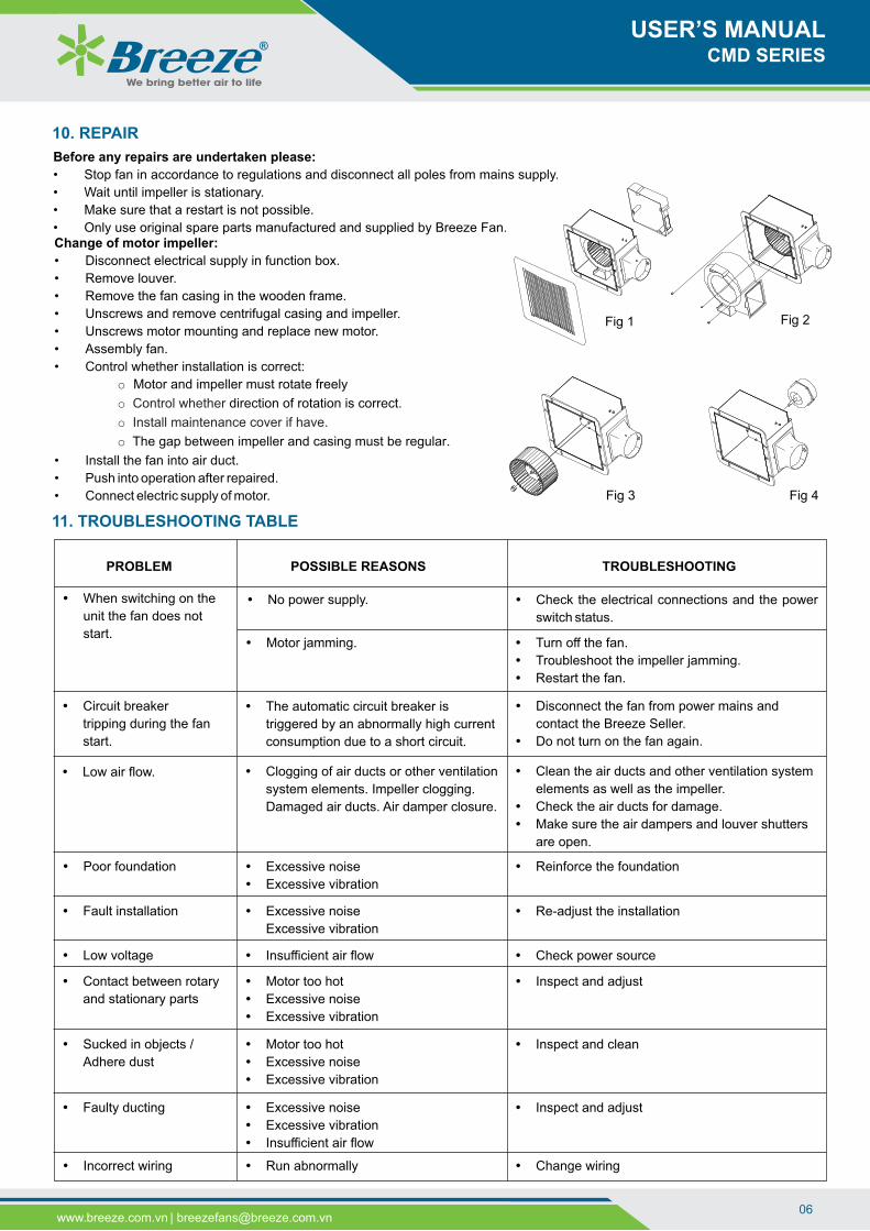
Change of motor impeller:
• Disconnect electrical supply in function box.
• Remove louver.
• Remove the fan casing in the wooden frame.
• Unscrews and remove centrifugal casing and impeller.
• Unscrews motor mounting and replace new motor.
• Assembly fan.
• Control whether installation is correct:
o Motor and impeller must rotate freely
direction of rotation is correct. o Control whether
o Install maintenance cover if have.
o The gap between impeller and casing must be regular.
• Install the fan into air duct.
• Push into operation after repaired.
• Connect electric supply of motor.
10. REPAIR
Before any repairs are undertaken please:
• Stop fan in accordance to regulations and disconnect all poles from mains supply.
• Wait until impeller is stationary.
• Make sure that a restart is not possible.
• Only use original spare parts manufactured and supplied by Breeze Fan.
USER’S MANUALCMD SERIES
Fig 1 Fig 2
Fig 3 Fig 4

07www.breeze.com.vn | [email protected]
We bring better air to life
Transport
• Our products are packed at the factory to suit the respectively agreed mode of transportation. Transport the fan in its original
packaging.
• Fans are protected against damage during shipment. If the unit cannot be installed and operated immediately, precautions need
to be taken to prevent deterioration of the unit during storage. The user assumes responsibility of the fan and accessories while
in storage. The manufacturer will not be responsible for damage during storage. These suggestions are provided solely as a
convenience to the user.
• Only use suitable means of transport, such as pallet trucks or fork-lift trucks or hoist machine.
• If the fan is to be transported by hand, ensure that supporting and carrying loads are kept within reasonable limits for the
personnel involved.
• The fans must not be dropped or thrown. Avoid scratches or rough handling during loading and unloading.
• Parts which have been stacked too high can collapse.
• Avoid a distortion of casing or blades or other damage.
• Danger ! Do not step under hanging loads.
12. TRANSPORT AND STORAGE
Storage
• Store the unit in the manufacturer’s original packaging box in a dry closed ventilated premise with temperature range from +5˚С
up to +40˚С and relative humidity up to 85%.
• Store the fan in a dry, weather-protected location in its original packaging or protect it from the effects of dirt and the weather
until final assembly. Storage environment must not contain aggressive vapours and chemical mixtures provoking corrosion,
insulation and sealing deformation.
• Rotate fan impeller monthly and purge bearings once every three months.
• If storage of fan is in a humid, dusty or corrosive atmosphere, rotate the fan and purge the bearings once a month. Improper
storage which results in damage to the fan will void the warranty.
• Avoid lengthy storage periods (a maximum of one year is recommended) and check that the motor bearing assembly is in good
functional order prior to fitting. With storage times of more than 1 year, please check the bearings on soft running before
installation (turn by hand).
Thank you for your cooperations!
USER’S MANUALCMD SERIES

Applied standard:
BREEZE INDUSTRIAL VENTILATION JOINT STOCK COMPANY
Vietnam
Head Office:
215D8 Nguyen Van Huong Street, Thao Dien Ward,
District 2, Ho Chi Minh City, Vietnam.
Tel: +84 28 6651 8585 | Hotline: +84 931 920 368
Factory:
12 Road No. 570, Xom Moi Hamlet, Trung Lap Ha
Commune, Cu Chi District, Ho Chi Minh City, Vietnam.
Tel: +84 28 6659 9589
Ha Noi Office:
55, Alley No. 14, Vu Huu Street, Thanh Xuan Bac Ward,
Thanh Xuan District, Ha Noi City, Vietnam.
Tel: +84 24 6683 8797 | Hotline: +84 906 568 557.
Website: www.breeze.com.vn
Email: [email protected]
Singapore
Office:
No 15, Yishun Industrial Street
1, #03-29, WIN5 Singapore
S768091.
Tel: +65-6254-2648
Myanmar
Office:
No.13/B, Kan Yeik Thar
Street, Thingangyun
Township, Yangon, Myanmar.